product name: gr6 tie-back srl - amazon web services
TRANSCRIPT

Product Name: GR6 Tie-Back SRL
Instruction Manual
Part #: 32015; 32016
Do not throw away these instructions!Read and understand these instructions before using equipment!
Introduction 1
Applicable Safety Standards 1
Worker Classifications 1
Safety Information 9
Product Specific Applications 2
Limitations 2 - 3
Components and Specifications 4
Maintenance, Cleaning, and Storage 8
Inspection 8
Installation and Use 5 - 7
Inspection Log 8
Labels 10
GR
6 T
IE-B
AC
KS
EL
F-R
ET
RA
CT
ING
LI F
EL
INE
WE
B
DO
NO
T RE
MO
VE L
AB
ELS
Asse
mbl
ed in
USA
OS
HA
19
26
.50
2 &
19
10
.14
0
Anch
or P
oint
at/a
bove
D-ri
ngUs
er W
eight
Ran
ge: 1
30 -
420
lbs.
Max
. Dec
elera
tion
Dista
nce:
24”
Min
. Fall
Clea
ranc
e: 5’6
”
Anch
or P
oint
bel
ow D
-ring
(2’ M
ax.)
User
Weig
ht R
ange
: 130
- 31
0 lb
s.Ma
x. De
celer
ation
Dist
ance
: 44”
Mi
n. Fa
ll Clea
ranc
e: 9’2
” CA
UTION!
DO
NOT T
IE-B
ACK
ONTO
THE R
ETRA
CTAB
LE S
ECTI
ON
Whe
n us
ed in
a no
n-tie
-bac
k for
mat
, the l
ifelin
e mus
t ALW
AYS
be in
tens
ion.


Introduction
Thank you for purchasing a Guardian FallProtection GR6 Tie-Back SRL. This manualmust be read and understood in its entirety,and used as part of an employee trainingprogram as required by OSHA or anyapplicable state agency.
This and any other included instructionsmust be made available to the user ofthe equipment. The user must understandhow to safely and effectively use theGR6 Tie-Back SRL, and all fall safetyequipment used in combination with theGR6 Tie-Back SRL.
User Information
Date of First Use:
Serial #:
Trainer:
User:
Applicable Safety Standards
When used according to instruction specifications, this product meets or exceeds all applicable OSHA 1926.502and OSHA 1910.140 standards for fall protection. Applicable standards and regulations depend on thetype of work being done, and also might include state-specific regulations. Consult regulatory agencies formore information on fall protection systems and associated components.
Worker Classifications
! CAUTION Understand the following definitions of those whowork near or who may be exposed to fall hazards.
Qualified Person: A person with an accredited degree or certification, and with extensive experience orsufficient professional standing, who is considered proficient in planning and reviewing the conformity of fallprotection and rescue systems.
Competent Person: A highly trained and experienced person who is ASSIGNED BY THE EMPLOYER to beresponsible for all elements of a fall safety program, including, but not limited to, its regulation, management,and application. A person who is proficient in identifying existing and predictable fall hazards, and who hasthe authority to stop work in order to eliminate hazards.
Authorized Person: A person who is assigned by their employer to work around or be subject to potential orexisting fall hazards.
It is the responsibility of a Qualified or Competent person to supervise the job site and ensure allapplicable safety regulations are complied with.
G
uard
ian
Fall
Prot
ectio
n 6
305
S. 2
31st
St.
, Ken
t, W
A 9
8032
pho
ne: (
800)
466
-638
5 f
ax: (
800)
670
-789
2
ww
w.g
uard
ianf
all.c
om
1
Product Specific Applications
Personal Fall Arrest: GR6 Tie-Back SRL may be used to support a MAXIMUM 1 PFAS for use in FallArrest applications. Structure must withstand loads applied in the directions permitted by thesystem of at least 5,000 lbs. Maximum 2’ free fall (note: reduced weight capacity and increaseddeceleration distance if free fall exists). Applicable D-ring: Dorsal.
Restraint: GR6 Tie-Back SRL may be used in Restraint applications. Restraint systems preventworkers from reaching the leading edge of a fall hazard. Always account for fully deployed lengthof lanyard/SRL. Structure must withstand loads applied in the directions permitted by the systemof at least 1,000 lbs. No free fall is permitted. Restraint systems may only be used on surfaceswith slopes up to 4/12 (vertical/horizontal). Applicable D-rings: Dorsal, Chest, Side, Shoulder.
! WARNING Use of equipment in unintended applications may result in seriousinjury or death. Maximum 1 attachment per connection point.
Limitations
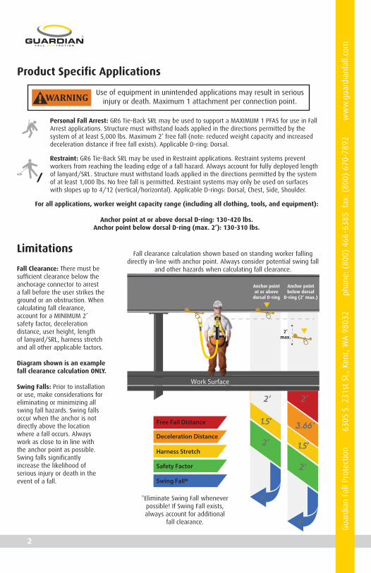
Fall Clearance: There must besufficient clearance below theanchorage connector to arresta fall before the user strikes theground or an obstruction. Whencalculating fall clearance,account for a MINIMUM 2’safety factor, decelerationdistance, user height, lengthof lanyard/SRL, harness stretchand all other applicable factors.
Diagram shown is an examplefall clearance calculation ONLY.
Swing Falls: Prior to installationor use, make considerations foreliminating or minimizing allswing fall hazards. Swing fallsoccur when the anchor is notdirectly above the locationwhere a fall occurs. Alwayswork as close to in line withthe anchor point as possible.Swing falls significantlyincrease the likelihood ofserious injury or death in theevent of a fall.
For all applications, worker weight capacity range (including all clothing, tools, and equipment):
Anchor point at or above dorsal D-ring: 130-420 lbs.Anchor point below dorsal D-ring (max. 2’): 130-310 lbs.
Fall clearance calculation shown based on standing worker fallingdirectly in-line with anchor point. Always consider potential swing fall
and other hazards when calculating fall clearance.
Anchor pointat or above
dorsal D-ring
Anchor pointbelow dorsal
D-ring (2’ max.)
2’max.
*Eliminate Swing Fall wheneverpossible! If Swing Fall exists,always account for additional
fall clearance.
3.66’
G
uard
ian
Fall
Prot
ectio
n 6
305
S. 2
31st
St.
, Ken
t, W
A 9
8032
pho
ne: (
800)
466
-638
5 f
ax: (
800)
670
-789
2
ww
w.g
uard
ianf
all.c
om
2

Compatibility: When making connections with GR6 Tie-Back SRL, eliminate all possibility of roll-out. Roll-outoccurs when interference between a hook and the attachment point causes the hook gate to unintentionallyopen and release. All connections must be selected and deemed compatible with GR6 Tie-Back SRL by aCompetent Person. All connector gates must be self-closing and self-locking, and withstand minimum loads of3,600 lbs. See the following for examples of compatible/incompatible connections:
Connectorclosed andlocked toD-ring. OK.
Two or moresnap hooks orcarabinersconnected toeach other. NO.
Two connectorsto sameD-ring. NO.
Connectordirectly tohorizontallifeline. NO.
Connectorto integrallanyard.NO.
Connectordirectly towebbing.NO.
Incompatibleor irregularapplication,which mayincrease riskof roll-out. NO.
G
uard
ian
Fall
Prot
ectio
n 6
305
S. 2
31st
St.
, Ken
t, W
A 9
8032
pho
ne: (
800)
466
-638
5 f
ax: (
800)
670
-789
2
ww
w.g
uard
ianf
all.c
om
3
GR
6 T
IE-B
AC
KS
EL
F-R
ET
RA
CT
ING
LI F
EL
INE
WE
B
DO
NO
T RE
MO
VE L
AB
ELS
Asse
mbl
ed in
USA
OS
HA
19
26
.50
2 &
19
10
.14
0
Anch
or P
oint
at/a
bove
D-ri
ngUs
er W
eight
Ran
ge: 1
30 -
420
lbs.
Max
. Dec
elera
tion
Dista
nce:
24”
Min
. Fall
Clea
ranc
e: 5’6
”
Anch
or P
oint
bel
ow D
-ring
(2’ M
ax.)
User
Weig
ht R
ange
: 130
- 31
0 lb
s.Ma
x. De
celer
ation
Dist
ance
: 44”
Mi
n. Fa
ll Clea
ranc
e: 9’2
” CA
UTION!
DO
NOT T
IE-B
ACK
ONTO
THE R
ETRA
CTAB
LE S
ECTI
ON
Whe
n us
ed in
a no
n-tie
-bac
k for
mat
, the l
ifelin
e mus
t ALW
AYS
be in
tens
ion.

Components and Specifications
Materials: stainless steel, glass-filled nylon, HMPE, and galvanized steel.
Part # Description
32015
32016
GR6 Tie-Back 6’ Single Leg SRL w/Steel Snap Hook
GR6 Tie-Back 6’ Dual Leg SRL w/Steel Snap Hook
GR6 TIE-BACKS E L F - R E T R A C T I N G L I F E L I N E
WEB
DO NOT REMOVE LABELS
Assembled in USA
OSHA 1926.502 & 1910.140
Anchor Point at/above D-ringUser Weight Range: 130 - 420 lbs. Max. Deceleration Distance: 24”
Min. Fall Clearance: 5’6”
Anchor Point below D-ring (2’ Max.)User Weight Range: 130 - 310 lbs.Max. Deceleration Distance: 44” Min. Fall Clearance: 9’2”
CAUTION! DO NOT TIE-BACK ONTO THE RETRACTABLE SECTIONWhen used in a non-tie-back format, the lifeline must ALWAYS be in tension.
ConnectionPoint
Shock Absorberw/ Cover
Tie-Back Lifeline(25/32” width)
Tie-BackSnap Hook
Housing
Stopper Ring
Average arrest force: 1,350 lbs. Maximum arrest force:1,800 lbs.
Anchor point at or above D-ring:- Maximum deceleration distance: 24”.- Minimum fall clearance: 5.5’
Anchor point below D-ring (max 2’):- Maximum deceleration distance: 44”.- Minimum fall clearance: 9’2”.
G
uard
ian
Fall
Prot
ectio
n 6
305
S. 2
31st
St.
, Ken
t, W
A 9
8032
pho
ne: (
800)
466
-638
5 f
ax: (
800)
670
-789
2
ww
w.g
uard
ianf
all.c
om
4

Installation and Use
• Guardian Fall Protection GR6 Tie-Back SRLs MUST NEVER be used in Leading Edge (LE) applications.
• ALWAYS avoid lifeline contact with sharp or abrasive edges and surfaces, both during use and inevent of a fall.
• For Dual Leg Kit (Part #: 32016), assemble and use SRL according to instruction sheet provided withDual SRL Bracket (part # 11058).
Tie-Back:
A) Wrap GR6 Tie-Back SRLwebbing around selectedstructural anchor. Ensurepotential free fall does notexceed what is permittedby the system, asdetermined by CompetentPerson. B) Attach snap hook towebbing BELOW stopperring. NEVER attach tie-backhook to or above stopper ring.
! WARNING In tie-back applications, snap hook must ONLY be attached to tie-backwebbing below stopper ring. NEVER attach snap hook above stopper ring.
Always use GR6 Tie-Back SRL in combination with anchorpoint that eliminates as much slack in lifeline as possible. Competent
Person must ensure that anchor point location will not introducepotential free fall greater than what is permitted by the system.
! WARNING
YES
NO
1. All components of the personal fall arrest system must be selected and deemed compatible with GR6Tie-Back SRL by a Competent Person.
2. Ensure area where work is to be performed is free of all hazards, including, but not limited to, debris, rot,rust, sharp or abrasive edges and surfaces, and hazardous materials.
3. If using dual leg GR6 Tie-Back SRL, ensure 100% tie-off will be maintained at all times; ALWAYS attachdisengaged hook to a compatible anchor point prior to unhooking engaged hook.
4. GR6 Tie-Back SRLs must be used either in tie-back or standard applications. Adhere to the applicablemethod of installation and use.
! WARNING Do not remove shrink tube around shock absorber.
G
uard
ian
Fall
Prot
ectio
n 6
305
S. 2
31st
St.
, Ken
t, W
A 9
8032
pho
ne: (
800)
466
-638
5 f
ax: (
800)
670
-789
2
ww
w.g
uard
ianf
all.c
om
5
GR6 TIE-BACKS E L F - R E T R A C T I N G L I F E L I N E
WEB
DO NOT REMOVE LABELS
Assembled in USA
OSHA 1926.502 & 1910.140
Anchor Point at/above D-ringUser Weight Range: 130 - 420 lbs. Max. Deceleration Distance: 24”
Min. Fall Clearance: 5’6”
Anchor Point below D-ring (2’ Max.)User Weight Range: 130 - 310 lbs.Max. Deceleration Distance: 44” Min. Fall Clearance: 9’2”
CAUTION! DO NOT TIE-BACK ONTO THE RETRACTABLE SECTIONWhen used in a non-tie-back format, the lifeline must ALWAYS be in tension.
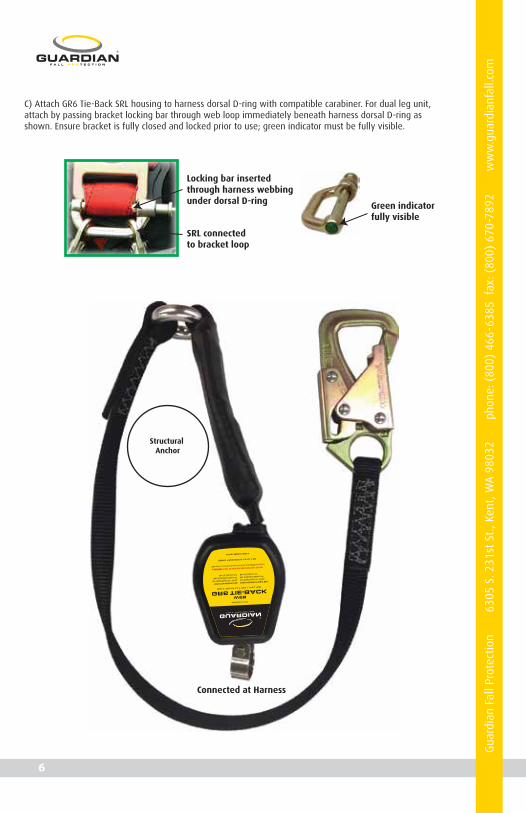
Green indicatorfully visible
SRL connectedto bracket loop
Locking bar insertedthrough harness webbingunder dorsal D-ring
C) Attach GR6 Tie-Back SRL housing to harness dorsal D-ring with compatible carabiner. For dual leg unit,attach by passing bracket locking bar through web loop immediately beneath harness dorsal D-ring asshown. Ensure bracket is fully closed and locked prior to use; green indicator must be fully visible.
Structural Anchor
Connected at Harness
G
uard
ian
Fall
Prot
ectio
n 6
305
S. 2
31st
St.
, Ken
t, W
A 9
8032
pho
ne: (
800)
466
-638
5 f
ax: (
800)
670
-789
2
ww
w.g
uard
ianf
all.c
om
6

Standard:
A) Attach GR6 Tie-Back SRL housing either to harness dorsal D-ring or to compatible overhead anchorageconnector with compatible carabiner. To locate housing at harness, connect single leg unit to dorsal D-ringwith compatible carabiner, and for dual leg unit attach by passing bracket locking bar through web loopimmediately beneath harness dorsal D-ring as shown. Ensure bracket is fully closed and locked prior to use;green indicator must be fully visible.
B) If housing is located at harness, attach snap hook to compatible overhead anchorage connector. If housingis located at anchorage connector, attach snap hook to harness dorsal D-ring. Always enure potential free falldoes not exceed what is permitted by the system, as determined by Competent Person.
Green indicatorfully visible
SRL connectedto bracket loop
Locking bar insertedthrough harness webbingunder dorsal D-ring
G
uard
ian
Fall
Prot
ectio
n 6
305
S. 2
31st
St.
, Ken
t, W
A 9
8032
pho
ne: (
800)
466
-638
5 f
ax: (
800)
670
-789
2
ww
w.g
uard
ianf
all.c
om
7
GR
6 T
IE-B
AC
KS
EL
F-R
ET
RA
CT
ING
LI F
EL
INE
WE
B
DO
NO
T RE
MO
VE L
AB
ELS
Asse
mbl
ed in
USA
OS
HA
19
26
.50
2 &
19
10
.14
0
Anch
or P
oint
at/a
bove
D-ri
ngUs
er W
eight
Ran
ge: 1
30 -
420
lbs.
Max
. Dec
elera
tion
Dista
nce:
24”
Min
. Fall
Clea
ranc
e: 5’6
”
Anch
or P
oint
bel
ow D
-ring
(2’ M
ax.)
User
Weig
ht R
ange
: 130
- 31
0 lb
s.Ma
x. De
celer
ation
Dist
ance
: 44”
Mi
n. Fa
ll Clea
ranc
e: 9’2
” CA
UTION!
DO
NOT T
IE-B
ACK
ONTO
THE R
ETRA
CTAB
LE S
ECTI
ON
Whe
n us
ed in
a no
n-tie
-bac
k for
mat
, the l
ifelin
e mus
t ALW
AYS
be in
tens
ion.

Maintenance, Cleaning, and Storage
If GR6 Tie-Back SRL fails inspection in any way, immediately remove it from service, and contact Guardian toinquire about its return or repair.
Cleaning after use is important for maintaining the safety and longevity of GR6 Tie-Back SRL. Remove all dirt,corrosives, and contaminants from GR6 Tie-Back SRL before and after each use. If GR6 Tie-Back SRL cannot becleaned with plain water, use mild soap and water, then rinse and wipe dry. NEVER clean GR6 Tie-Back SRLwith corrosive substances.
When not in use, store equipment where it will not be affected by heat, light, excessive moisture, chemicals,or other degrading elements.
Prior to EACH use, inspect GR6 Tie-Back SRL for deficiencies, including, but not limited to, corrosion,deformation, pits, burrs, rough surfaces, sharp edges, cracking, rust, paint buildup, excessive heating,alteration, and missing or illegible labels. IMMEDIATELY remove GR6 Tie-Back SRL from service if defects ordamage are found, or if exposed to forces of fall arrest.
Ensure that applicable work area is free of all damage, including, but not limited to, debris, rot, rust, decay,cracking, and hazardous materials. Ensure that selected work area will support the application-specificminimum loads set forth in this instruction manual. Work area MUST be stable.
At least every 12 months, a Competent Person other than the user must inspect GR6 Tie-Back SRL. CompetentPerson inspections MUST be recorded in inspection log in instruction manual and on equipmentinspection grid label. The Competent Person must sign their initials in the box corresponding to themonth and year the inspection took place.
During inspection, consider all applications and hazards GR6 Tie-Back SRL has been subjected to.
Inspection
Inspection Log
If equipment fails inspection IMMEDIATELY REMOVE FROM SERVICE.
Date of First Use: __________________.
Product lifetime is indefinite, as long as it passes all pre-use and Competent Person inspections. Usermust inspect prior to EACH use. Competent Person other than user must complete formal inspection atleast every 12 months. Competent Person to inspect and initial.
This inspection log must be specific to one GR6 Tie-Back SRL. Separate inspection logs must be used foreach GR6 Tie-Back SRL. All inspection records must be made visible and available to all users at alltimes.
G
uard
ian
Fall
Prot
ectio
n 6
305
S. 2
31st
St.
, Ken
t, W
A 9
8032
pho
ne: (
800)
466
-638
5 f
ax: (
800)
670
-789
2
ww
w.g
uard
ianf
all.c
om
8

Safety Information
Failure to understand and comply with safety regulations may result inserious injury or death. Regulations included herein are not all-inclusive,
are for reference only, and are not intended to replace a CompetentPerson’s judgment or knowledge of federal or state standards.
! WARNING
Do not alter equipment. Do not misuse equipment.
Workplace conditions, including, but not limited to, flame, corrosive chemicals, electrical shock, sharp objects,machinery, abrasive substances, weather conditions, and uneven surfaces, must be assessed by a CompetentPerson before fall protection equipment is selected.
The analysis of the workplace must anticipate where workers will be performing their duties, the routes theywill take to reach their work, and the potential and existing fall hazards they may be exposed to. Fallprotection equipment must be chosen by a Competent Person. Selections must account for all potentialhazardous workplace conditions. All fall protection equipment should be purchased new and in an unusedcondition.
Fall protection systems must be selected and installed under the supervision of a Competent Person, and usedin a compliant manner. Fall protection systems must be designed in a manner compliant with all federal, state,and safety regulations. Forces applied to anchors must be calculated by a Competent Person.
Unless explicitly stated otherwise, the maximum allowable free fall distance for lanyards must not exceed 6’.No free fall allowed for non-LE SRLs. Class A SRLs must arrest falls within 24”; Class B SRLs must arrest fallswithin 54”.
Harnesses and connectors selected must be compliant with manufacturer’s instructions, and must be ofcompatible size and configuration. Snap hooks, carabiners, and other connectors must be selected and appliedin a compatible fashion. All risk of disengagement must be eliminated. All snap hooks and carabiners must beself-locking and self-closing, and must never be connected to each other.
A pre-planned rescue procedure in the case of a fall is required. The rescue plan must be project-specific. Therescue plan must allow for employees to rescue themselves, or provide an alternative means for their promptrescue. Store rescue equipment in an easily accessible and clearly marked area.
Training of Authorized Persons to correctly erect, disassemble, inspect, maintain, store, and use equipmentmust be provided by a Competent Person. Training must include the ability to recognize fall hazards, minimizethe likelihood of fall hazards, and the correct use of personal fall arrest systems.
NEVER use fall protection equipment of any kind to hang, lift, support, or hoist tools or equipment, unlessexplicitly certified for such use.
Equipment subjected to forces of fall arrest must immediately be removed from use.
Age, fitness, and health conditions can seriously affect the worker should a fall occur. Consult a doctor if thereis any reason to doubt a user’s ability to withstand and safely absorb fall arrest forces or perform set-up ofequipment. Pregnant women and minors must not use this equipment.
Physical harm may still occur even if fall safety equipment functions correctly. Sustained post-fall suspensionmay result in serious injury or death. Use trauma relief straps to reduce the effects of suspension trauma.
G
uard
ian
Fall
Prot
ectio
n 6
305
S. 2
31st
St.
, Ken
t, W
A 9
8032
pho
ne: (
800)
466
-638
5 f
ax: (
800)
670
-789
2
ww
w.g
uard
ianf
all.c
om
9
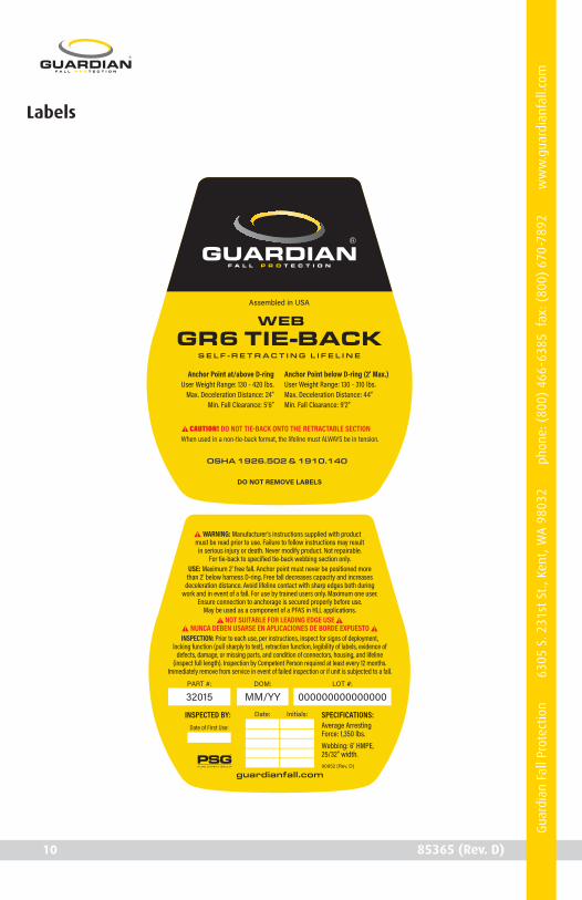
Labels
90952 (Rev. C)
G
uard
ian
Fall
Prot
ectio
n 6
305
S. 2
31st
St.
, Ken
t, W
A 9
8032
pho
ne: (
800)
466
-638
5 f
ax: (
800)
670
-789
2
ww
w.g
uard
ianf
all.c
om
10 85365 (Rev. D)
GR6 TIE-BACKS E L F - R E T R A C T I N G L I F E L I N E
WEB
DO NOT REMOVE LABELS
Assembled in USA
OSHA 1926.502 & 1910.140
Anchor Point at/above D-ringUser Weight Range: 130 - 420 lbs.
Max. Deceleration Distance: 24” Min. Fall Clearance: 5’6”
Anchor Point below D-ring (2’ Max.)User Weight Range: 130 - 310 lbs.Max. Deceleration Distance: 44” Min. Fall Clearance: 9’2”
CAUTION! DO NOT TIE-BACK ONTO THE RETRACTABLE SECTIONWhen used in a non-tie-back format, the lifeline must ALWAYS be in tension.
90952 (Rev. D)
Date of First Use:
guardianfall.com
WARNING: Manufacturer's instructions supplied with product must be read prior to use. Failure to follow instructions may result
in serious injury or death. Never modify product. Not repairable.For tie-back to specified tie-back webbing section only.
USE: Maximum 2’ free fall. Anchor point must never be positioned more than 2’ below harness D-ring. Free fall decreases capacity and increases
deceleration distance. Avoid lifeline contact with sharp edges both during work and in event of a fall. For use by trained users only. Maximum one user.
Ensure connection to anchorage is secured properly before use. May be used as a component of a PFAS in HLL applications.
NOT SUITABLE FOR LEADING EDGE USENUNCA DEBEN USARSE EN APLICACIONES DE BORDE EXPUESTO
INSPECTION: Prior to each use, per instructions, inspect for signs of deployment, locking function (pull sharply to test), retraction function, legibility of labels, evidence of
defects, damage, or missing parts, and condition of connectors, housing, and lifeline (inspect full length). Inspection by Competent Person required at least every 12 months.
Immediately remove from service in event of failed inspection or if unit is subjected to a fall.
SPECIFICATIONS:Average Arresting Force: 1,350 lbs.Webbing: 6’ HMPE,25/32” width.
DOM:
MM/YYPART #:
32015LOT #:
000000000000000Date: Initials:INSPECTED BY: