product manual 04048 (revision c)
TRANSCRIPT

Product Manual 04048(Revision C)
Original Instructions
SG Governor
This manual replaces manual 04022.
Installation and Operation Manual

DEFINITIONS
This is the safety alert symbol. It is used to alert you to potential personal injury hazards. Obey all safety messages that follow this symbol to avoid possible injury or death.
DANGER—Indicates a hazardous situation which, if not avoided, will result in death or serious injury.
WARNING—Indicates a hazardous situation which, if not avoided, could result in death or serious injury.
CAUTION—Indicates a hazardous situation which, if not avoided, could result in minor or moderate injury.
NOTICE—Indicates a hazard that could result in property damage only (including damage to the control).
IMPORTANT—Designates an operating tip or maintenance suggestion.
The engine, turbine, or other type of prime mover should be equipped with an overspeed shutdown device to protect against runaway or damage to the prime mover with possible personal injury, loss of life, or property damage.
The overspeed shutdown device must be totally independent of the prime mover control system. An overtemperature or overpressure shutdown device may also be needed for safety, as appropriate.
Read this entire manual and all other publications pertaining to the work to be performed before installing, operating, or servicing this equipment. Practice all plant and safety instructions and precautions. Failure to follow instructions can cause personal injury and/or property damage.
This publication may have been revised or updated since this copy was produced. To verify that you have the latest revision, be sure to check the publications page on the Woodward website:
www.woodward.com/publications The current revision and distribution restriction of all publications are shown in manual 26311. The latest version of most publications is available on the publications page. If your publication is not there, please contact your customer service representative to get the latest copy.
Any unauthorized modifications to or use of this equipment outside its specified mechanical, electrical, or other operating limits may cause personal injury and/or property damage, including damage to the equipment. Any such unauthorized modifications: (i) constitute "misuse" and/or "negligence" within the meaning of the product warranty thereby excluding warranty coverage for any resulting damage, and (ii) invalidate product certifications or listings.
To prevent damage to a control system that uses an alternator or battery-charging device, make sure the charging device is turned off before disconnecting the battery from the system.
To prevent damage to electronic components caused by improper handling, read and observe the precautions in Woodward manual 82715, Guide for Handling and Protection of Electronic Controls, Printed Circuit Boards, and Modules.
Woodward reserves the right to update any portion of this publication at any time. Information provided by Woodward is believed to be correct and reliable. However, no responsibility is assumed by Woodward unless otherwise expressly undertaken.
Copyright © Woodward 1986 All Rights Reserved

Manual 04048 SG Governor
Woodward i
Contents
CHAPTER 1. GENERAL INFORMATION ........................................................... 1 Introduction ............................................................................................................. 1 Governor Drive ....................................................................................................... 1 Speed Adjustment .................................................................................................. 2 Speed Droop Adjustment ....................................................................................... 3 Auxiliary Features (Optional) .................................................................................. 3
CHAPTER 2. PRINCIPLES OF OPERATION ..................................................... 4
CHAPTER 3. INSTALLATION AND ADJUSTMENT ............................................. 6 Installation .............................................................................................................. 6 Linkage ................................................................................................................. 10 Adjustment ............................................................................................................ 12 Troubleshooting .................................................................................................... 13
CHAPTER 4. OVERHAUL ............................................................................ 14 Introduction ........................................................................................................... 14 Disassembly Instructions ...................................................................................... 14 Repair ................................................................................................................... 18 Assembly Instructions ........................................................................................... 19
CHAPTER 5. PARTS INFORMATION ............................................................. 24 Cover Assembly with Bodine Speed Adjusting Motor .......................................... 28 Cover Assembly with Pittman PM Speed Adjusting Motor ................................... 30 Cover Assembly with Vertical Return Spring ........................................................ 32 Subcap Assemblies .............................................................................................. 34
CHAPTER 6. TROUBLESHOOTING ............................................................... 42 General ................................................................................................................. 42 Oil Trouble ............................................................................................................ 42 Speed Droop Adjustment ..................................................................................... 42 Analysis and Correction of Governing Troubles ................................................... 42
CHAPTER 7. PRODUCT SUPPORT AND SERVICE OPTIONS ........................... 45 Product Support Options ...................................................................................... 45 Product Service Options ....................................................................................... 45 Returning Equipment for Repair ........................................................................... 46 Replacement Parts ............................................................................................... 46 Engineering Services ............................................................................................ 47 Contacting Woodward’s Support Organization .................................................... 47 Technical Assistance ............................................................................................ 48

SG Governor Manual 04048
ii Woodward
Illustrations and Tables Figure 1-1. Typical SG Governor with New Style Cover ........................................ 2 Figure 1-2. Early Type SG Governor ...................................................................... 2 Figure 2-1. Schematic Diagram of a Typical SG Governor .................................... 5 Figure 3-1. Recommended Engine Oil System for Quick Starts ............................ 7 Figure 3-2. SG Governor Outline with Direct Pneumatic Speed Setting ................ 8 Figure 3-3. SG Governor Outline with Reverse Pneumatic Speed Setting ............ 8 Figure 3-4. SG with Fuel Rod and Bodine Electric Motor for Speed Setting.......... 9 Figure 3-5. Wiring Diagram for Bodine Motor (Switch not furnished) ..................... 9 Figure 3-6. Wiring Diagram for PM Motor (switch not furnished) ......................... 10 Figure 3-7. Recommended Governor Terminal Shaft Travel ............................... 10 Figure 3-8. Linear Linkage Arrangement .............................................................. 11 Figure 3-9. Non-linear Linkage Arrangement ....................................................... 12 Figure 4 1 Bushing Driver ..................................................................................... 17 Figure 4-2. Bushing and Gear Stud Replacement ............................................... 20 Figure 4-3. Centering Pilot Valve Plunger ............................................................ 22 Figure 5-1. Typical SG Governor Parts (later models) ......................................... 25 Figure 5-2. Typical SG Governor Parts (early models) ........................................ 27 Figure 5-3. Bodine Speed Adjusting Motor and Installation Parts ........................ 29 Figure 5-4. Speed Adjusting Motor Parts ............................................................. 29 Figure 5-5. Pittman PM Speed Adjusting Motor and Installation Parts ................ 31 Figure 5-5a. Vertical Return Spring Cover and Installation Parts ........................ 33 Figure 5-6. Subcap Assembly Parts (linear output) .............................................. 35 Figure 5-7. Subcap Assembly Parts (internal return spring) ................................ 36 Figure 5-8. Spring driven, Oil-Damped Ballhead Parts ........................................ 37 Figure 5-9. Spring-Driven Ballhead Parts ............................................................. 38 Figure 5-10. Outline Drawing of SG Governor with Speed Adjusting Motor ........ 39 Figure 5-11. Outline Drawing of SG Governor with Subcap (internal return spring)
and Speed Adjusting Motor ............................................................. 40 Figure 5-12. Outline Drawing of SG Governor with and without PM Motor, with
Pneumatic Speed Setting Assembly ............................................... 41

Manual 04048 SG Governor
Woodward 1
Chapter 1. General Information
Introduction This manual provides description, operation, overhaul and replacement parts information for SG governors (Figure 1-1) and various optional auxiliary features. The SG governor is a hydraulic speed droop type governor used on small diesel, gas, or gasoline engines where isochronous (constant speed) control is not required. The design of the speed droop governor is such that the governor operates at a slower speed as engine load increases. It is through this characteristic that stability of the governed system is achieved, and division of load between paralleled units made possible. SG governors are available with 10.8 or 21.7 inch-pounds (1.2 or 2.5 J) of work capacity over 36° of terminal shaft (output) travel.
The torque, work capacity, and maximum work values of the SG governor are based on 25 psi (172 kPa) supply oil pressure to the governor. These values can vary depending on the supply oil pressure.
If not supplied with an internal return spring, the 10.8 inch-pound governor requires an external return spring (not furnished by Woodward) that exerts a 20 pound-inch (2.3 Nm) torque on the terminal shaft in the closing direction. The 21.7 inch-pound governor requires a spring that exerts a 40 pound-inch (4.5 Nm) torque on the terminal shaft in the closing direction. A new cover for the standard SG governor is a vertical return-spring type cover. This cover is used with or without a return spring, and also, with or without a Pittman PM (Permanent Magnet) speed-setting motor. For SG governors without a motor, the cover is furnished with a guide plug for the low-speed stop screw (see Figures 1-1 and 1-2). The SG governor is usually arranged to operate at 2400 or 3600 rpm at normal rated engine speed, and will control down to approximately 25% of normal speed. Special configurations are available, however, to meet other speed requirements. The governor uses engine oil or oil from a separate sump (not furnished by Woodward) as a control medium; it does not have an independent sump.
Governor Drive The governor drive shaft is splined to fit into the engine drive (see Figures 5-11 and 5-12). The governor may be mounted vertically or horizontally. If mounted horizontally, the terminal shaft must also be horizontal and a 3/8-inch drain line provided to connect to a 1/4-inch pipe-tapped or 0.438-20 (-4) straight-thread port in the tower end of the governor cover. For connection of the drain line on the new-style cover, see Figure 1-2 for vertical installation or Figure 5-12 for horizontally mounted governors.

SG Governor Manual 04048
2 Woodward
The governor drive shaft may be rotated in either direction. However, the governor relief valve assembly must, when viewing the governor from the nameplate end, be on the left if the governor is rotated clockwise (when viewed from above). The relief valve assembly must be on the right for counterclockwise rotation of the drive.
Figure 1-1. Typical SG Governor with New Style Cover
Figure 1-2. Early Type SG Governor
Speed Adjustment The speed adjusting shaft is used to set the governor for the desired running speed. Low speed and high speed stop screws are provided to limit the speed range of variable speed governors. If the engine is to be operated at one speed setting, the stop screws may be used to lock the position of the speed adjusting shaft.

Manual 04048 SG Governor
Woodward 3
The terminal shaft may extend on either or both sides of the governor. Shutdown of the engine can be accomplished by turning the speed adjusting shaft below the idle speed setting position.
Speed Droop Adjustment Speed droop adjustment is provided inside the governor. The droop setting required to gain stability varies with each installation; in most instances it must be set to increase unit speed two or three percent over the terminal shaft rotation used from rated power output at rated speed to zero power output. The range of adjustment is from one-half of one percent to approximately seven percent over the full 36° available travel of the governor terminal shaft.
Auxiliary Features (Optional) Speed Adjusting Motor The SG governor can be fitted with a speed adjusting motor to enable the switchboard operator to match the frequency of an alternator with that of other units or a system before synchronizing, and to change load distribution after synchronizing. Two types of motor are available. The Bodine motor is of the split field, series wound, reversible type (see Figures 3-8and 3-9). It is available in all standard voltages. The Pittman motor is of the permanent magnet type 12 or 24 Vdc (see Figures 5-3 and 5-5). When motor supply voltage is other than 12 or 24 Vdc, the following control boxes are available for conversion to 24 Vdc: 24 Vdc P/N 8272-515 110 Vdc P/N 8272-518 110 Vdc P/N 8272-516 220 Vdc P/N 8272-517 A manual speed adjusting knob with friction clutch assembly is included on units fitted with a speed adjusting motor. Vibration Attenuating Ballhead Assemblies A spring-driven oil-damped ballhead assembly (Figure 5-8) may be used in SG governors in place of the standard solid ballhead assembly where it is necessary to overcome undesirable torsional vibrations transmitted from the engine drive to the governor ballhead. Subcap Assemblies Different subcap assemblies are available to match the particular needs of the SG governor installation (see Figures 5-7 and 5-12). Figure 5-7 illustrates the subcap used for an installation with a linear output, Figure 5-12 illustrates a rotary output with an internal return spring. Subcaps usually include a fuel-rack stop screw.

SG Governor Manual 04048
4 Woodward
Chapter 2. Principles of Operation
A schematic arrangement of a typical SG governor is shown in Figure 2-1. As described earlier, the governor uses engine oil as a control medium and does not have an independent sump. The engine oil enters the governor at the relief valve, drops down into the cavity on the suction side of the governor oil pump, and is carried by the pump gears around to the pressure side of the pump. If the supply of pressure oil is greater than is required for governing purposes, the governor pump will build up pressure until the relief valve plunger is pushed to the right against the force of the relief valve plunger spring. The governor pump will then recirculate the oil within the governor. If pressure oil is used for governing purposes, the pressure will be reduced and the spring will move the relief valve plunger to the left. The recirculating passage is thus blocked so that operating pressure is maintained. The pilot valve plunger controls the movement of the power piston by directing oil to and from the area beneath the power piston. The power piston, operating through the power piston pin and terminal lever, positions the terminal shaft to which the engine fuel linkage connects. When the governor is running on-speed, the control land of the pilot valve plunger covers the control port of the ballhead bushing, and the power piston remains stationary. If the engine load is increased, the governor speed decreases, and speeder spring force—now greater than the lifting effect of the centrifugal force developed by the rotating ballarms—pushes the pilot valve plunger down. Pressure oil is directed to the area under the power piston and pushes the piston up. The power piston and pin rotate the terminal lever and terminal shaft in the direction to increase fuel. Note that, as the terminal lever rotates in the “increase fuel” direction, the speed droop pin is raised. The right end of the floating lever pivots about the speed adjusting lever pin as the left end of the lever is raised. Raising the left end of the floating lever raises the spring fork and decreases the speeder spring force. Thus, the governor ballhead is enabled to re-center the pilot valve plunger at lower speeds as fuel is increased, a characteristic described as “speed droop”. Closing the control port stops further movement of the power piston simultaneously with return of the engine to the lower speed, a speed determined by the new speeder spring force. If the engine load is decreased, the governor speed increases and the ballarms lift the pilot valve plunger against the downward force of the speeder spring. The uncovered control port in the ballhead bushing connects the oil under the power piston to sump. The absence of pressure under the power piston allows the external spring force to rotate the terminal shaft and terminal lever in the “decrease fuel” direction. When moving in the decrease fuel direction, the terminal lever lowers the speed droop pin. The floating lever lowers the spring fork to increase the speeder spring force. The increase in speeder spring force re-centers the pilot valve plunger, and requires an increase in speed to keep it centered. Closing the control port stops further movement of the power piston simultaneously with return of the engine to the higher speed required by the higher spring force.

Manual 04048 SG Governor
Woodward 5
The amount of speed change for a given terminal shaft rotation depends upon the setting of the speed droop pin. Moving the pin towards the ballhead decreases the speed change; moving it away from the ballhead increases the speed change.
Figure 2-1. Schematic Diagram of a Typical SG Governor

SG Governor Manual 04048
6 Woodward
Chapter 3. Installation and Adjustment
Installation Introduction These instructions apply to three types of SG governors differentiated by their speed settings: Lever Pneumatic Electric Additional considerations for governors with pneumatic or electric speed setting are listed under respective headings. Direction of Rotation Rotation of the governor drive shaft as viewed from the top of the governor must be the same as that of the engine drive when looking down on the mounting pad. When the governor is to be rotated clockwise (when viewed from above), the governor relief valve assembly must, when viewing the governor from the nameplate end, be on the left. When the governor is to be rotated counterclockwise (when viewed from above), the governor relief valve assembly must, when viewing the governor from the nameplate end, be on the right.
Be sure engine mounting-pad drive and governor drive rotation are the same. Incorrect drive rotation will cause the governor to become inoperative and may cause governor damage.
Place a gasket between the base of the governor and the engine mounting pad. Mount the governor square with the engine drive and in line with the linkage. The splined drive shaft must fit the engine drive freely with no tightness. Do not force the governor onto the mounting pad.
Be sure the gasket does not block off the three drain holes In the base. See Figures 5-10, 5-11, and 5-12.
Oil Supply Connect a 0.250 inch ID oil supply line to the 0.125 inch pipe-tapped hole in the relief valve. Oil from the engine must supply a minimum of 5 psi (34 kPa) to the governor. If a separate sump is used, the distance the governor must lift the oil should not exceed 12 inches (30 cm), and a foot valve with a capacity of 2 US gallons per minute (7.6 L/min) must be used. Use a 2 USgal/min (7.6 L/min), 40 µm filter in the oil supply line. In suction lift applications, the filter must not be in series with the inlet line to the governor. Keep oil lines as short as possible.

Manual 04048 SG Governor
Woodward 7
If mounted horizontally, the terminal shaft must also be horizontal and a 3/8 inch external drain line provided to connect to either a 1/4-Inch pipe tapped hole or 0.438-20 (-4) straight-thread port In the lower end of the governor cover or subcap. See Figure 5-12 to connect the drain to the new style cover when the governor is mounted horizontally. Use a supply system similar to Figure 3-1 for applications requiring quick starts.
Figure 3-1. Recommended Engine Oil System for Quick Starts Minimum drainage or siphon level is that oil level in the governor below which the governor pump gears are no longer submerged in oil. Oil level in the oil tank must always be as high as, or higher than, this line. If not, governor pump gears are no longer submerged in oil and will cavitate when the prime mover is started, causing possible loss of governor control.
Most problems of mechanical hydraulic governors occur because of dirty oil. Be sure to use clean oil.
Keep the end of the overboard drain line above the engine sump oil level. Most standard 1 to 2 quart housings (approximately 1 to 2 L), with filter omitted, can be adapted for this system. Pneumatic Speed Setting There are two types. The reverse acting increases speed with a decrease in air pressure, while the direct acting increases speed with an increase in air pressure. The pneumatic speed-setting cover has two tapped holes for the oil reservoir. Use one of the two holes for the reservoir and plug the other. Always mount the oil reservoir with the hole for the air connection up. Be sure the other hole is plugged (see outline drawing, Figure 3-2 or 3-3). Install the governor on the engine. Using a funnel, fill the oil reservoir to approximately 3/8 inch (10 mm) from the top via the hole for the air connection in top of the reservoir. Attach the air signal pressure line to the hole in top of the oil reservoir.

SG Governor Manual 04048
8 Woodward
Figure 3-2. SG Governor Outline with Direct Pneumatic Speed Setting
Figure 3-3. SG Governor Outline with Reverse Pneumatic Speed Setting

Manual 04048 SG Governor
Woodward 9
Electric Speed Setting The Bodine motor and the PM motor are coupled to the governor speed-setting mechanism through a friction clutch. If the operator runs the speed adjustment to its limit, the clutch is set to slip, thereby protecting the speed-adjusting motor. Connect the electric speed setting as shown in Figure 3-5 or 3-6. Figure 3-5 is for the Bodine motor, and Figure 3-6 is for the PM motor. Voltage for the Bodine motor is shown on the motor.
Figure 3-4. SG with Fuel Rod and Bodine Electric Motor for Speed Setting
Figure 3-5. Wiring Diagram for Bodine Motor (Switch not furnished)
The permanent magnet motor operates on dc power. If a 115 or 230 Vac or Vdc power source is used, convert the power source to 24 to 32 Vdc. A converter can be ordered from Woodward. See Chapter 1, Speed Adjusting Motor.
Connect to correct voltage. If a new cover and PM motor is ordered for use on an existing governor, all that is required to install the new cover is to remove the old cover and set the new assembly In place. If some adjustment is necessary. loosen the screws holding the PM motor in place and align the motor shaft with the clutch. Apply Loctite 242 or equivalent to the screws and tighten to 10 lb-in (1.1 Nm).

SG Governor Manual 04048
10 Woodward
Figure 3-6. Wiring Diagram for PM Motor (switch not furnished) When the cover is used without the PM motor, a screw is placed in the hole where the motor drive shaft normally fits. This screw is then used as a low-speed stop. The cover also houses a vertical return spring when one is used.
Linkage Linear Use a linear linkage for diesel-engine applications. Adjust the fuel linkage to provide control of engine fuel from the minimum to the maximum engine fuel stops. Use two-thirds of the output shaft travel between the fuel rack’s no load and full load positions. See Figure 3-7 for recommended governor terminal shaft travel. Adjust the maximum-fuel-rack stop screw to obtain the maximum output rotation. Maximum rotation for vertical-return-spring governors is 40°. Maximum rotation for other units is 36°.
Figure 3-7. Recommended Governor Terminal Shaft Travel

Manual 04048 SG Governor
Woodward 11
Attach the fuel rack linkage to the governor output shaft. Be sure there is no lost motion or binding in the linkage. See Figure 3-8 for linear linkage arrangement.
Be sure to allow sufficient overtravel at each end of the terminal shaft so the governor can shut down the engine and also give maximum fuel when required.
The torque and work capacity values quoted are based on 25 psi (172 kPa) supply pressure to the governor. These values can vary, depending on the oil supply pressure.
Figure 3-8. Linear Linkage Arrangement Governor output can be with either terminal shaft or with fuel rod: connect linkage accordingly. Some subcaps with a fuel rod have a knob which can be pushed in to open the fuel racks when starting an engine, or pulled out to close the fuel racks and stop the engine. Non-Linear Applications involving a butterfly valve, such as on a gas engine, require a non-linear linkage. Figure 3-9 illustrates the relationship between governor output shaft and butterfly obtained with simple linkage of maximum non-linearity. When installing this linkage, make sure the two following conditions are attained when the linkage is in the no-load position: 1. The lever which is attached to the governor and the connecting link is in line
with the governor output shaft and the point of attachment of the connecting link to the butterfly lever.
2. The butterfly lever must be at 90 degrees with the connecting link. Refer to the prime-mover manufacturer’s manual for the correct linkage selection and installation.

SG Governor Manual 04048
12 Woodward
Figure 3-9. Non-linear Linkage Arrangement
Adjustment Starting the Engine for the First Time Start the engine as instructed by the engine manufacturer. For a safe start-up, adjust the governor for a reduced speed and allow the engine to warm up.
Be prepared to make an emergency shutdown when starting the engine, turbine, or other type of prime mover, to protect against runaway or overspeed with possible personal injury, loss of life, or property damage.
Make the following adjustments to the governor only if the engine does not stabilize, The governor was adjusted at the factory and should not require any adjustment.
Speed Droop Adjustment (The cover must be removed to access the speed droop adjustment. Use caution if internal return springs are used. See Figure 5-1, part 15, or Figure 5-2, part 111.) SINGLE ENGINE OPERATION—If engine speed does nor stabilize, shut down the engine. Increase droop slightly (about 0.0625 inch [1.588 mm] movement of bracket away from the governor ballhead), and restart the engine. Manually move the engine fuel linkage to cause a temporary engine speed change. Continue to increase the droop until operation is satisfactory. Not enough droop can cause instability in the form of hunting, surging, or difficulty in response to a load change. Too much droop can result in slow governor response in picking up or dropping off load. OPERATING IN PARALLEL WITH OTHER ALTERNATORS—Droop is used to divide and balance load between units driving the same shaft or paralleled in the electrical system. It total load does not divide properly, increase droop on units taking too much of the load.

Manual 04048 SG Governor
Woodward 13
On interconnected units, set the least amount of droop possible to provide satisfactory load division.
The no load to full load speed change must be equal for all paralleled units.
Adjust the speed setting of SG governors or other governors with speed droop to get distribution of load between synchronized units. Increasing the speed setting of a particular unit will increase the load on that unit.
If the governor output shaft does not use the full 2/3 of available travel from “NO LOAD” TO “FULL LOAD”, droop wilt also be reduced proportionately.
Normally, the amount of droop set into the SG governor to make it stable in a system will be enough to allow the units to parallel.
Troubleshooting If engine hunts or surges: a. Adjust and align linkage, check for lost motion, binding, excessive friction,
and linearity of load to governor travel. b. Increase speed droop. c. Make sure that the ballhead cavity is not lull of oil. This could be a drain
problem. If engine speed increases as load increases: a. Increase droop slightly. Load does not divide properly on interconnected engines: This applies when load is increased or decreased. and speed setting is constant. a. Repeat speed droop adjustment. b. Check voltage regulator droop. c. Adjust droop to divide load properly. d. Increase droop to resist picking up (or dropping off) load. e. Reduce droop to increase picking up (or dropping off) load. f. Adjust droop and tighten screw securely. Engine will not pick up rated full load: a. Adjust and align fuel linkage, check for lost motion, binding, excessive
friction, and linearity of load to governor travel. b. Adjust maximum speed stop. c. Check speed-adjusting linkage, if present, for interference. d. Check for insufficient fuel flow. e. If engine is at maximum fuel stop and still cannot pick up rated full load, the
problem is elsewhere in the system and not in the governor. Governor oil overflows: Make sure that oil flow through the two drain holes is not restricted by the gasket between the governor base and engine. See Figure 5-10 for drain holes.

SG Governor Manual 04048
14 Woodward
Chapter 4. Overhaul
Introduction The components of the SG governor have undergone substantial modification since first introduced. For this reason it is imperative that requests for information or parts for SG governors include: Governor model and serial number as shown on governor nameplate. Manual number (this is manual 04048). Part reference number and name or description of part. Exploded views of the most recent and early versions of the SG governor are shown in Figures 5-1 and 5-2.
Disassembly Instructions Governor It is suggested that the best mechanic available—preferably one with small parts assembly experience—be assigned to all governor maintenance and repair work. Cleanliness of tools and work area is essential to a satisfactory overhaul of any governor. Aside from the usual hand tools, one would require only a pair of Waldes No. 2 external snap ring pliers. A work bench with vise, an arbor press, and containers for cleaning solvents should be provided. If the governor is to be taken apart completely, proceed in this manner: 1. Clamp the governor lightly in a vise; vise jaws must grasp the base below
the base-case joint on the sides under the terminal shaft. 2. Remove cover screws. Lift off cover. Use caution if a return spring is
present. At this point, inspection of the terminal lever (13, Figure 5-1, or 113, Figure
5-2) will reveal whether the governor is of the type shown in Figure 5-1 or Figure 5-2. The first number following in parenthesis identifies parts shown in Figure 5-1; the second number, parts shown in Figure 5-2.
3. Remove speed droop screw (10/109), washer(s) (11 and 12/110), and
bracket (15/111). 4. Remove cotter pins (14/112) from terminal lever (13/113). 5. Remove long terminal shaft (37/136) and synthetic rubber seals (36/135). 6. Insert a 5/16-inch diameter rod in the opening left by the long terminal shaft
and drive short terminal shaft (39/138) out; plug (32/139) will be forced out at this time.
7. Remove terminal lever (13/113) from the governor.

Manual 04048 SG Governor
Woodward 15
8. Make a note of the distance the high speed stop screw (29/128) protrudes from the governor case so that it can be set approximately the same when reassembling. Remove stop screw (29/1 28), locknut (30/129), and washer (31/—).
9. Remove speed adjusting shaft (35/134) as follows: Figure 5-1— A. Using a 1/8-inch diameter punch or rod, drive roll pin (26) out of speed
adjusting lever (27) and into the governor case. B. Pull speed adjusting shaft (35) out of the case. C. Lift out the assembly consisting of speed adjusting lever (27), pilot
valve plunger (20), thrust bearing (21), and connecting parts. Remove torsion spring (34).
If the governor is equipped with a spring-driven ballhead, see Figure 5-8 or 5-9. Parts are not available for the ballhead shown in Figure 5-9.
On those governors in which the speed adjusting shaft does not stick out through governor case, remove shaft as follows: D. Drive roll pin (26) out of speed adjusting lever (27) as in step A above. E. Remove spring wire pin (28) and lift out floating lever (25), pilot valve
(20), thrust bearing (21), and connecting parts. F. Using a soft (brass) rod against the speed adjusting lever—hold the rod
against either side of lever as close to the shaft as possible—drive lever (27) and bushing (33) out until welch plug (32) pops out of case.
G. Insert a 5/16-inch diameter rod in the hole left by the welch plug and
drive the speed adjusting shaft back in the other direction, knocking the other welch plug out.
H. Pull the shaft out, removing speed adjusting lever (27) and torsion
spring (34) as the shaft is withdrawn. Figure 5-2— A. Unscrew speed adjusting sleeve (133) and spacer cap (130)—each
with a copper gasket (131). B. Lift out the assembly consisting of speed adjusting shaft (134), pilot
valve (118), thrust bearing (119), and connecting parts. C. Remove cotter pin (124) and speed adjusting shaft (134) from
assembly just removed. 10. Disassemble speed adjusting lever (27/126), floating lever (25/125), and
spring fork (18/116) by twisting off the bent end of spring wire pin (28/123). 11. Remove plug (41/141) opposite the relief valve assembly and copper gasket
(42/131).

SG Governor Manual 04048
16 Woodward
12. Remove relief valve assembly as follows: Figure 5-1— A. Remove oil inlet plug (47) and copper gasket (42). B. Remove springs (46 and 45). C. Remove relief valve plunger (60) and sleeve assembly (43).
If the plunger and sleeve cannot be removed easily with a small pair of long-nosed pliers (or tweezers) and a hook scriber, leave them in place until step 17.
Figure 5-2— D. Remove relief valve sleeve (146) and copper gasket (131). The sleeve
contains the other elements of the relief valve assembly. 13. Remove the governor from the vise and invert it, catching, in— Figure 5-1—power piston pin (16), power piston (17), and roll pin (26)
(driven out of speed adjusting lever earlier); Figure 5-2—power piston (114). 14. If the governor has a spring-driven ballhead assembly (Figure 5-8 or 5-9),
remove snap ring (306/324) under the ballarms (310/329) and lift out the ballhead (311/328).
15. Remove snap ring (S7/157) or collar (—/159) from drive shaft. Lift out
ballhead assembly (22, 23, 24, Figure 5-1; 120, 121, 122, Figure 5-2; 306 through 314, Figure 5-8). Remove press-fit collar (—/159) by driving the shaft into the base using a plastic or other soft hammer.
16. Remove three screws (58/155), and remove governor base (55/154). If the
base does not separate easily from the case, clamp the base, governor nameplate side of case up, lightly in a vise. Using a plastic or soft hammer, tap the underside of the case to loosen it from base.
Hold a hand under the base-case joint to catch the pump gears which may drop out as the base and case are separated.
Remove pump gears (52, 53/151, 152) and seal ring (54/153). 17. If the relief valve sleeve and plunger (Figure 5-1) could not be removed in
step 12C, insert a 3/16-inch diameter rod in the tapped hole opposite the relief valve opening, push plunger (60) out, and pull out the sleeve assembly (43).
Case If necessary to replace the idler gear stud, terminal sleeves, oil seals, or bushings, proceed as follows:

Manual 04048 SG Governor
Woodward 17
Figure 5-1— 1. Clamp idler gear stud (51) in a vise. Twist and pull the case to remove the
stud.
Be careful not to score the bottom surface of the case.
2. Drive out plugs (32) and bushings (33 and 38) using a 3/8-inch diameter rod and a piloted driving block similar to that shown in Figure 4-1. In each instance, drive the bushings outward (rather than towards the center of the case).
Figure 5-2— 3. Remove idler stud (150) as outlined in step 1 above. 4. Drive terminal sleeves (137) out of case. Use the piloted driving block
shown in Figure 4-1, or insert a 5/1 6-inch diameter threaded rod through one side of the case, install a nut, and drive out the sleeve.
5. Remove synthetic rubber seals (135) if not already taken out. 6. Press bushings (132) out of sleeves (137) if worn.
Figure 4 1 Bushing Driver Spring Fork, Speeder Spring, and Pilot Valve Plunger Figure 5-1 or 5-2— 1. Twist speeder spring (19/117) to detach from pilot valve plunger (20/118). 2. Clamp spring fork (18/116) in a vise with the pin hole up. Using a thin
screwdriver or small punch, drive the speeder spring off the fork. 3. On some early modal governors (Figure 5-2), pilot valve plunger (161) may
be pressed out of spring seat (160). The pilot valve plunger and spring seat are one piece in Figure 5-1.
Figure 5-8— 4. Twist speeder spring assembly (301) to detach from spring seat (304). The
speeder spring and spring fork are a bonded assembly and must not be disassembled. Replace the assembly if the bond has separated.
5. Do not disturb the position of, or remove spring seat (304) from, pilot valve
plunger (305) unless replacement of parts is necessary. Should the relationship of these parts be disturbed for any reason, the pilot valve plunger must be re-centered in the bushing at time of reassembly. If disassembly is necessary, hold the pilot valve plunger with a screwdriver while loosening the nut.

SG Governor Manual 04048
18 Woodward
Relief Valve Previous steps have removed the relief valve elements of governors shown in Figure 5-1. 1. The relief valve assembly in Figure 5-2 will have either plunger (162) or
bushing (142) and plunger (143). 2. To remove plunger (162), insert long-nosed pliers in the end of the sleeve,
push the plunger down, and grip pin (145). Slide the pin out and remove the plunger and spring (144).
3. To remove bushing (142) and plunger (143), insert a small sharp chisel in
the end of the bushing. With a sharp blow, cut pin (145). Remove the broken pin. Insert a small rod in the threaded end of the relief valve and push out the bushing, plunger, and spring (144).
Ballhead Assemblies SOLID BALLHEAD ASSEMBLY—Grind off one end of ballarm pins (23/121 or 164) to remove ballarms. SPRING-DRIVEN OIL-DAMPED BALLHEAD ASSEMBLY (FIGURE 5-8) 1. Remove snap ring (306) under ballarms (310) and then pull pilot valve
bushing (307) out of the ballhead. 2. Support drive cup (314) on a 1 or 1-1/8-inch (25 or 29 mm) diameter pipe or
wooden dowel and press off ballhead cover (308). Use a 3-inch (76 mm) long pipe or tube machined to 2.150 (+0.005–0.000) [54.61 (+0.13–0.00) mm] inside diameter and a depth of 0.750 inch (19.05 mm) as a pusher.
3. Lift off ballhead (311) and remove pins (309) and ballarms (310). 4. Remove torsion spring (312) and ball bearing (313) from drive cup (314). SPRING-DRIVEN BALLHEAD ASSEMBLY (FIGURE 5-9) This ballhead has been replaced by the oil damped version shown in Figure 5-8. Spare parts are no longer available. 1. Remove spiral retaining ring (323). 2. Remove ballarm pins (326) and ballarms (329). 3. Lift the centering spring coupling assembly (325) out of ballhead (328).
Repair Most repair work consists of cleaning and polishing of parts. Use 320 to 500 grit emery cloth for polishing. All pistons should move freely without binding or catching. Excessive clearance between mating parts, however, will result in excessive leakage of pressure oil within the governor.

Manual 04048 SG Governor
Woodward 19
Pilot Valve Plunger Be extremely careful when polishing the pilot valve plunger control land. Leave the corners sharp. Broken or rounded corners on this land will ruin the pilot valve plunger. Case If the ground bottom surface of the case is grooved or worn from rotation of the pump gears, or scratched from mishandling, it may be surface ground to clean-up. Up to 1/32 inch (0.79 mm) material may be removed. Lap the surface smooth on a flat plate if a surface grinder is not available. Base If the ground flat surface of the base is warped, nicked, or deeply scratched, it may be lapped smooth on a flat plate. Do not remove more material than necessary to clean-up. If the depth of the gear pockets is reduced, the gears will bind. In this event, the faces of the gears must be lapped to provide clearance. Pump Gears The pump gears should be laid in the gear pockets and tested for free rotation. If the gears turn roughly, inspect for nicks or wear of gear teeth and for interference at the internal corners of the gear pockets in the base.
Assembly Instructions Handle parts with care during assembly. In general. the assembly procedure is the reverse of the disassembly operation. Assembly suggestions follow. Case Figure 5-1— If necessary to install new bushings (33 and 38), press the bushings in with an arbor press to the dimensions shown in Figure 4-2. Press in the idler gear stud to the depth shown in Figure 4-2. After installing the bushings, line size or line ream with standard 3/8-inch diameter line reamer. Figure 5-2— Press bushings (132) in flush with small end of terminal sleeves (137). Press the terminal sleeves into the case; sleeve shoulder to be tight against case. (Insert a support plate of exactly the correct width between the inside walls of the case.) Press in the gear stud. The stud should project 3/8 inch (9.5 mm) out of the case. Press bushings (132) in flush with each end of speed adjusting sleeve (133). After installing the bushings, line size or line ream with standard 3/8-inch diameter line reamer.

SG Governor Manual 04048
20 Woodward
Figure 4-2. Bushing and Gear Stud Replacement Ballhead Assemblies SOLID BALLHEAD ASSEMBLY (FIGURE 5-1 or 5-2)—Use new ballarm pins (23/121) and lightly upset each end to retain in position. SPRING-DRIVEN OIL-DAMPED BALLHEAD ASSEMBLY (FIGURE 5-8)—Reassemble ballhead components (309 through 314) and then press on ballhead cover (308). A minimum force of 90 pounds (400 N) should be required to reinstall a used cover, or a minimum of 100 pounds (445) for a new cover. The top edge of the cover must be flush with the top surface of the ballhead. If the cover is pressed too far, it will bind on the drive cup and result in erratic or no vibration dampening. Take care not to bend or otherwise distort the base or walls of the cup. Case and Base Figures 5-1 or 5-2 1. Drive dowel pins (56/156) out of the base. 2. Place the pump gears in the gear pockets of the base.

Manual 04048 SG Governor
Woodward 21
3. Coat the surface of the base with oil. Do not use shellac. 4. Place base seal ring (54/153) in the base groove. If gasket (158, Figure 5-2)
is reused, it must not be torn or compressed to less than 0.003 inch (0.08 mm). If so, use a new 0.005-inch (0.13 mm) thick gasket. Do not tap out a new gasket with a hammer since this may round the sharp edges of gear pockets.
5. Place the case on the base, invert, and insert the ballhead-drive shaft
assembly through the bottom of the base to permit rotation of the pump gears (the ballhead and ballarms now stick outside of the governor). On governors in which the drive shaft is integral with the pump drive gear, the shaft projects through the base to provide a means of rotating the pump gears.
6. Insert the base screws and tighten while turning the ballhead (or drive shaft)
to ensure free rotation of gears. 7. Insert the dowel pins and drive them down approximately 1/16 inch (1.6
mm) below the base surface. Remove the ballhead drive shaft. 8. On governors using snap ring (57/157), place the ballhead and drive shaft
assembly into position in the governor case. Use snap ring pliers to install the snap ring.
On governors using a drive shaft collar (159, Figure 5-2), clamp a 1 to
1-3/16 inch (25 to 30 mm) diameter sleeve or pipe having a 5/8 inch (15.9 mm) diameter bore upright in a vise. Place the ballhead-drive shaft assembly into position in the governor and slip the drive shaft collar over the drive shaft. Hold the governor on the sleeve with the drive shaft slipping into the 5/8 inch diameter hole with the collar resting against the sleeve. Place a 7/18 inch (9.9 mm) diameter brass rod on the ballhead between the ballarms, and drive the collar onto the drive shaft. Take the governor off the drive sleeve and lap the end of the drive shaft lightly with a plastic or soft hammer until the drive shaft turns freely with a minimum of end play.
9. Turn the drive shaft with your fingers. If it binds, loosen the screws slightly
and free-up by striking at the corners of the base. Tighten screws and recheck.
Spring Fork, Speeder Spring and Pilot Valve Plunger Figure 5-1 or 5-2 1. Reassemble spring seat and pilot valve plunger (160 and 161, Figure 5-2), if
necessary. 2, Attach spring fork (18/116) to conical shaped speeder springs (19/117) by
“winding” the fork into the spring. 3. Wind the spring and fork assembly firmly into the spring seat on the pilot
valve plunger (20/118). 4. Each end of speeder spring must be securely attached to its mating part.
SG Governor Manual 04048
22 Woodward
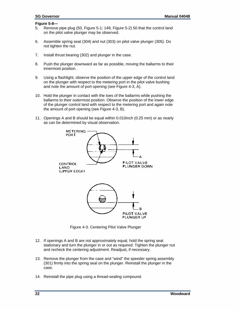
Figure 5-8— 5. Remove pipe plug (50, Figure 5-1; 149, Figure 5-2) 50 that the control land
on the pilot valve plunger may be observed. 6. Assemble spring seat (304) and nut (303) on pilot valve plunger (305). Do
not tighten the nut. 7. Install thrust bearing (302) and plunger in the case. 8. Push the plunger downward as far as possible, moving the ballarms to their
innermost position. 9. Using a flashlight, observe the position of the upper edge of the control land
on the plunger with respect to the metering port in the pilot valve bushing and note the amount of port opening (see Figure 4-3, A).
10. Hold the plunger in contact with the toes of the ballarms while pushing the
ballarms to their outermost position. Observe the position of the lower edge of the plunger control land with respect to the metering port and again note the amount of port opening (see Figure 4-3, B).
11. Openings A and B should be equal within 0.010inch (0.25 mm) or as nearly
as can be determined by visual observation.
Figure 4-3. Centering Pilot Valve Plunger 12. If openings A and B are not approximately equal, hold the spring seat
stationary and turn the plunger in or out as required. Tighten the plunger nut and recheck the centering adjustment. Readjust, if necessary.
13. Remove the plunger from the case and “wind” the speeder spring assembly
(301) firmly into the spring seal on the plunger. Reinstall the plunger in the case.
14. Reinstall the pipe plug using a thread-sealing compound.

Manual 04048 SG Governor
Woodward 23
Relief Valve Figure 5-1— Be sure relief valve plunger (60) moves freely in relief valve sleeve (43) (plunger installed with small diameter towards inside of governor). The sleeve must fit freely into the case bore. Figure 5-2— Plunger (143 or 162) must move freely in sleeve (146). If of the type using bushing (142), rotate the bushing 90° from the previous alignment, press in flush with the end of the sleeve, and drill a 1/16 inch (1.6 mm) diameter hole for new pin (145). Use pin holes in relief valve sleeve (146) as pilot holes when drilling the bushing.

SG Governor Manual 04048
24 Woodward
Chapter 5. Parts Information
When ordering replacement parts it is essential that the following information be given. Governor model, serial number, and part number (shown on nameplate);
needed since a manual reference number does not identify the exact part required for any one governor.
Manual number (this is manual 04048). Part reference number as given in the parts list, figure number showing part,
and name or description of part. Figures 5-1 and 5-2 illustrate the most common versions of the SG governor. Figures 5-3 through 5-9 illustrate the various optional features which may be used with these governors. Parts List, Figure 5-1
Ref. No. Part Name ............................. Quantity 04048-1 Cover .................................................. 1 04048-2 Low speed stop screw ........................ 1 04048-3 Hex. nut. 1/4-28 .................................. 1 04048-4 Vent screw .......................................... 1 04048-5 Lockwasher ......................................... 1 04048-6 Pipe plug, 1/4 ...................................... 1 04048-7 Sems fastener, 10-32 x 1 ............ 3 or 5 04048-8 Not used 04048-9 Cover gasket ....................................... 1 04048-10 Fil. hd. screw, 10-32 x 1/2 ................... 1 04048-11 Shakeproof washer, #10 ..................... 1 04048-12 Washer ............................................... 1 04048-13 Terminal lever ..................................... 1 04048-14 Cotter pin, 3/32 x 1 ............................. 2 04048-15 Speed droop adjusting bracket ........... 1 04048-16 Pin ....................................................... 1 04048-17 Power piston ....................................... 1 04048-18 Spring fork .......................................... 1 04048-19 Speeder spring ................................... 1 04048-20 Pilot valve plunger .............................. 1 04048-21 Thrust bearing ..................................... 1 04048-22 Ballarm ................................................ 2 04048-23 Ballarm pin .......................................... 2 04048-24 Ballhead—Pilot valve bushing ............ 1 04048-25 Floating lever ...................................... 1 04048-26 Roll pin ................................................ 1 04048-27 Speed adjusting lever ......................... 1 04048-28 Spring wire pin .................................... 1 04048-29 High speed stop screw, 10-32 x 1-1/4 1 04048-30 Nut, 10-32 ........................................... 1
Ref. No. Part Name ............................. Quantity 04048-31 Copper washer ................................... 1 04048-32 Welch plug ...................................... AR 04048-33 Bushing .............................................. 2 04048-34 Torsion spring .................................... 1 04048-35 Speed adjusting shaft ........................ 1 04048-36 Oil seal ............................................ AR 04048-37 Terminal shaft (Long) ......................... 1 04048-38 Bushing .............................................. 2 04048-39 Terminal shaft (Short) ........................ 1 04048-40 Case ................................................... 1 04048-41 Plug .................................................... 1 04048-42 Copper gasket .................................... 2 04048-43 Relief valve sleeve assembly ............. 1 04048-44 Deleted 04048-45 Relief valve plunger spring ................. 1 04048-46 Relief valve sleeve spring .................. 1 04048-47 Oil inlet plug ....................................... 1 04048-48 Nameplate .......................................... 1 04048-49 Drive screw, #2 .................................. 2 04048-50 Pipe plug, 1/8 ..................................... 1 04048-51 Idler gear stud .................................... 1 04048-52 Idler gear ............................................ 1 04048-53 Drive gear .......................................... 1 04048-54 Base seal ring .................................... 1 04048-55 Base ................................................... 1 04048-56 Dowel pin ........................................... 2 04048-57 Snap ring ............................................ 1 04048-58 Fil hd. screw, 10-24 a 1/2 ................... 3 04048-59 Deleted 04048-60 Relief valve plunger ........................... 1

Manual 04048 SG Governor
Woodward 25
Figure 5-1. Typical SG Governor Parts (later models)

SG Governor Manual 04048
26 Woodward
Parts List, Figure 5-2 Ref. No. Part Name ............................. Quantity 04048-101 Cover .................................................. 1 04048-102 Low speed stop screw ........................ 1 04048-103 Hex, nut, 1/4-28 .................................. 1 04048-104 Vent screw .......................................... 1 04048-105 Lock washer ........................................ 1 04048-106 Fil. hd. screw, 10-32 x 1 ...................... 3 04048-107 Shakeproof washer, #10 ..................... 3 04048-108 Cover gasket ....................................... 1 04048-109 Hex. hd. screw .................................... 1 04048-110- Washer ............................................... 1 04048-111 Speed droop adjusting bracket ........... 1 04048-112 Cotter pin ............................................ 2 04048-113 Terminal lever ..................................... 1 04048-114 Power piston ....................................... 1 04048-115 Pin ....................................................... 1 04048-116 Spring fork .......................................... 1 04048-117 Speeder spring ................................... 1 04048-118 Pilot valve plunger .............................. 1 04048-119 Thrust bearing ..................................... 1 04048-120 Ballarm ................................................ 2 04048-121 Ballarm pin .......................................... 2 04048-122 Ballhead—Pilot valve bushing ............ 1 04048-123 Spring wire pin .................................... 1 04048-124 Cotter pin ............................................ 1 04048-125 Floating lever ...................................... 1 04048-126 Speed adjusting lever ......................... 1 04048-127 Pin ....................................................... 1 04048-128 High speed stop screw ....................... 1 04048-129 Nut ...................................................... 1 04048-130 Spacer cap .......................................... 1 04048-131 Copper gasket .................................... 4 04048-132 Bushing ............................................... 4
Ref. No. Part Name ............................. Quantity 04048-133 Speed adjusting sleeve ...................... 1 04048-134 Speed adjusting shaft ........................ 1 04048-135 Synthetic rubber seal ......................... 4 04048-136 Terminal shaft (Long) ......................... 1 04048-137 Terminal sleeve .................................. 2 04048-138 Terminal shaft (Short) ........................ 1 04048-139 Welch plug ......................................... 1 04048-140 Case ................................................... 1 04048-141 Plug .................................................... 1 04048-142 Bushing .............................................. 1 04048-143 Relief valve plunger ........................... 1 04048-144 Relief valve spring .............................. 1 04048-145 Pin ...................................................... 1 04048-146 Relief valve sleeve ............................. 1 04048-147 Nameplate .......................................... 1 04048-148 Drive screw, #2 .................................. 2 04048-149 Pipe plug, 1/8 ..................................... 1 04048-150 Idler gear stud .................................... 1 04048-151 Idler gear ............................................ 1 04048-152 Drive gear .......................................... 1 04048-153 Base seat ring .................................... 1 04048-154 Base ................................................... 1 04048-155 Screw ................................................. 3 04048-156 Dowel pin ........................................... 2 04048-157 Snap ring ............................................ 1 04048-158 Base gasket ....................................... 1 04048-159 Drive collar ......................................... 1 04048-160 Spring seat ......................................... 1 04048-161 Pilot valve plunger .............................. 1 04048-162 Relief valve plunger ........................... 1 04048-163 Ballarm pin washer ............................ 4 04048-164 Ballarm pin ......................................... 2

Manual 04048 SG Governor
Woodward 27
Figure 5-2. Typical SG Governor Parts (early models)

SG Governor Manual 04048
28 Woodward
Cover Assembly with Bodine Speed Adjusting Motor Adjustments A friction coupling is incorporated in these cover assemblies to permit overtravel of the motor with no resulting damage. This coupling should be adjusted to slip at 4.5 to 5.5 lb-in (0.5 to 0.6 Nm) of torque. The motor must be mounted in such a manner as to center the shaft in the coupling. Full travel of the shaft in each direction should produce no binding. Bearing Lubrication Use Regal A oil or a good 10 weight oil for bearing lubrication. Under normal, intermittent operation, apply 5 drops of oil to the oil hole and oil cup every year. If the motor is run for long periods of time, apply 5 drops of oil to the oil hole and oil cup every six months. Gear Lubrication The speed reduction gear housing of a new motor is filled with sufficient lubricant to last for two years under normal, intermittent operation. Under extensive use, when the motor is run for long periods of time, the lubricant will last about one year. To replace grease, clean out the old grease and refill the gear housing 3/4 full of one of the following greases: Bodine Supermil Grease No. A72832, by Standard Oil Company Dow Corning Grease No, 44, when specified (temperature range is –40 to
+400 °F/–40 to +204 °C). Make sure the ball thrust bearing is reinstalled with the gearbox.
Parts List, Figure 5-3 Ref. No. Part Name ............................. Quantity 04048-201 Motor ..................................................... 04048-202 Friction cover ........................................ 04048-203 Friction disc ........................................... 04048-204 Friction spring ....................................... 04048-205 Set screw, 6-32 ..................................... 04048-206 Speed adjusting screw .......................... 04048-207 Cover .................................................... 04048-208 Copper washer, 0.203 x 3/8 x 1/32 ....... 04048-209 Fit hd. screw, 10-32 x 3/4 ..................... 04048-210 Lockwire ................................................ 04048-249 Micarta washer .....................................
Parts List, Figure 5-4 Ref. No. Part Name ............................. Quantity 04048-211 Motor brush ........................................ 2 04048-212 Brush spring ....................................... 2 04048-213 Worm shaft ......................................... 1 04048-214 Bakelite gear ...................................... 1 04046-215 Brushholder cap screw ...................... 2 04048-216 Brushholder ........................................ 2 04048-217 Bronze gear ....................................... 1 04048-218 End shield (Front) .............................. 1 04048-219 Gear housing ..................................... 1 04048-220 Field frame assembly (Complete) ...... 1 04048-221 Armature (Complete) ......................... 1 04046-222 Output shaft ....................................... 1

Manual 04048 SG Governor
Woodward 29
Figure 5-3. Bodine Speed Adjusting Motor and Installation Parts
Figure 5-4. Speed Adjusting Motor Parts

SG Governor Manual 04048
30 Woodward
Cover Assembly with Pittman PM Speed Adjusting Motor
Adjustments A friction coupling is incorporated in these cover assemblies to permit overtravel of the motor with no resulting damage. This coupling should be adjusted to slip at 4.5 to 5.5 lb-in (0.5 to 0.6 Nm) of torque and be locked in place with set screw (205). The motor must be mounted in such a manner as to center the shaft in the coupling. Full travel of the shaft in each direction should produce no binding. High-slip torque clutches use two springs (349) and are adjusted to 8 to 10 lb-in (0.9 to 1.1 Nm) slip torque. Parts List, Figure 5-5 Ref. No. Part Name ................................... Quantity 04048-341 Screw ....................................................... 4 04048-342 Bracket ..................................................... 1 04048-343 Motor Cover ............................................. 1 04048-344 Foam Buffer ............................................. 1 04048-345 PM Motor ................................................. 1
NOTE—Items 343, 344, and 345 are epoxied together as an assembly and are furnished that way only.
04048-346 Friction Clutch .......................................... 1 04048-347 Friction Disc ............................................. 1 04048-348 Washer .................................................... 1 04048-349 Friction Washer Spring ............................ 1 04048-350 Speed Adjusting Screw ............................ 1 04048-351 Cover ....................................................... 1 04048-352 Seal .......................................................... 1 04048-353 Flat Washer .............................................. 1 04048-354 Nut ........................................................... 1 04048-355 Stop Screw ............................................... 1 04048-356 Set Screw................................................. 1

Manual 04048 SG Governor
Woodward 31
Figure 5-5. Pittman PM Speed Adjusting Motor and Installation Parts

SG Governor Manual 04048
32 Woodward
Cover Assembly with Vertical Return Spring Parts List, Figure 5-5a Ref. No. Part Name ................................... Quantity 04048-361 Hex. screw, 250-28 x 2.250 ..................... 1 04048-362 Hex. nut, .250-28, SS ............................... 2 04048-363 Washer, 265 x .500 x .032 thick, SS ........ 2 04048-364 Seal, 1/4 Nitrite thread ............................. 2 04048-365 Plug, low speed guide .............................. 1 04048-366 Cover ....................................................... 1 04048-367 Soc. hd. cap screw, 10-32 x 1.500 ........... 5 04048-368 Hex. hd. stop screw, .250-28 x 3.000 ....... 1 04048-369 Gasket ..................................................... 1 04048-370 Spring, vertical return ............................... 1 04048-371 Elastic hex. nut (thin), 10-32 .................... 1 04048-372 Spring seat ............................................... 1 04048-373 Lever assembly ........................................ 1 04048-374 Strut pivot pin ........................................... 1 04048-375 Soc. hd. cap screw 10-32 x .875 .............. 2 04048-376 Servo-piston strut ..................................... 1 04048-377 Servo-piston ............................................. 1

Manual 04048 SG Governor
Woodward 33
Figure 5-5a. Vertical Return Spring Cover and Installation Parts

SG Governor Manual 04048
34 Woodward
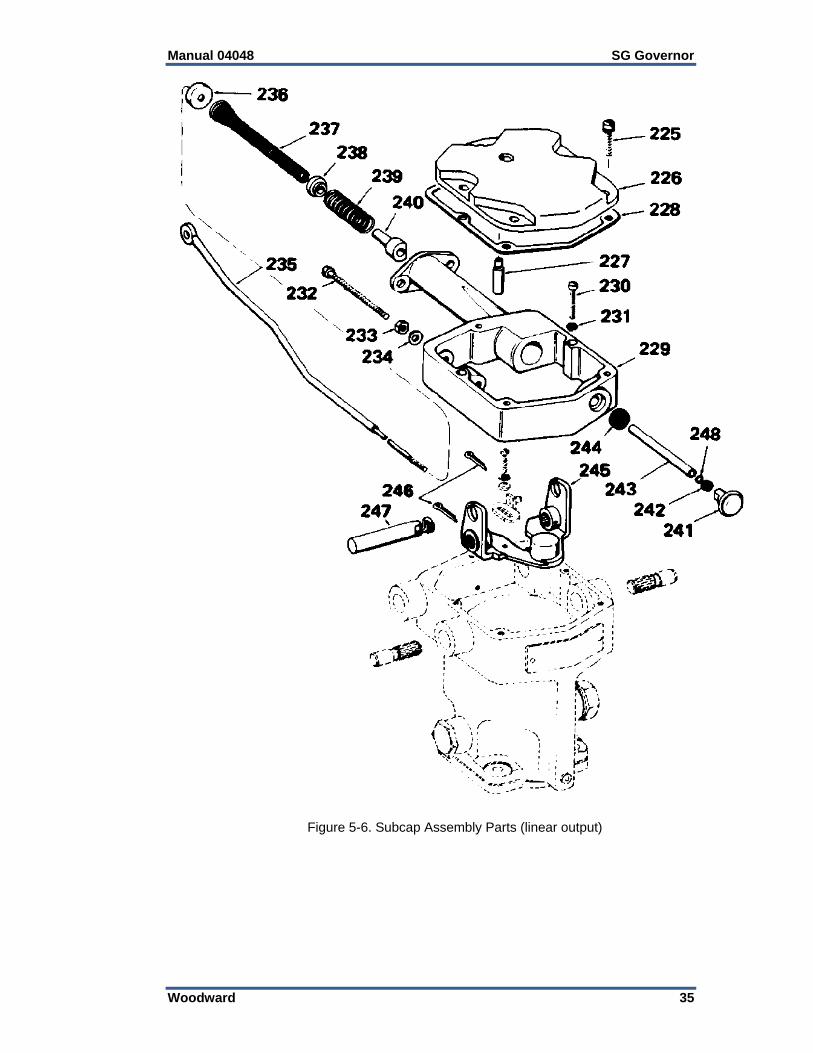
Subcap Assemblies The parts comprising typical subcap assemblies are shown in Figures 5-6 and 5-7. Except for the subcap assembly, the operation and construction of a governor equipped with a subcap are similar to the conventional governors described in preceding pages. Governors with subcaps do not require an external spring acting in the shutdown direction since the subcap springs perform the same function. The output of a governor with the subcap assembly shown in Figure 5-6 is at fuel rod (235) rather than at a terminal shaft. As in other model SG governors, the terminal lever (245) is rotated by the power piston movement as fuel changes are called for by the governor ballhead and pilot valve. The terminal lever pin (247), pushing against fuel rod collar (240), effects the movement of the fuel rod. Maximum fuel to the engine is limited by the setting of stop screw (232) which limits the angular travel of the terminal lever. The fuel rod spacer (243) is positioned by the setting of hex nut (242), and must be adjusted to match the engine linkage. The engine manufacturer’s manual provides instructions for this adjustment. After the hex nut is properly set, use knob (241) to lock it in position. Knob (241) provided on the front of the subcap assembly may be manually pushed in to open the fuel racks when starting, or pulled out to close the fuel racks and stop the engine. Some governors are equipped with the subcap assembly shown in Figure 5-7. The purpose of this type of subcap assembly is to provide a spring force within the governor to urge the terminal lever in the “fuel off” direction. Parts List, Figure 5-6 Ref. No. Part Name ................................... Quantity 04048-225 Some Fastener, fil hd., 10-32 x 1-3/8 ....... 5 04048-226 Cover ....................................................... 1 04048-227 Speed adjusting lever stop ....................... 1 04048-228 Gasket ..................................................... 1 04048-229 Subcap ..................................................... 1 04048-230 Screw, fiI. hd., 10-32 x 1 .......................... 2 04048-231 Lock washer, #10 ..................................... 2 04048-232 Stop screw ............................................... 1 04048-233 Lock nut, 1/4-28 ....................................... 1 04048-234 Washer .................................................... 1 04048-235 Fuel rod .................................................... 1 04048-236 Plug .......................................................... 1 04048-237 Spring ...................................................... 1 04048-238 Fuel rod disc ............................................ 1 04048-239 Spring ...................................................... 1 04048-240 Fuel rod collar .......................................... 1 04048-241 Knob ........................................................ 1 04048-242 Lock nut, 10-32 ........................................ 1 04048-243 Fuel rod spacer ........................................ 1 04048-244 Oil seal ..................................................... 1 04048-245 Terminal lever .......................................... 1 04048-246 Cotter pin ................................................. 2 04048-247 Terminal lever pin .................................... 1 04048-248 Gasket ..................................................... 1
Manual 04048 SG Governor
Woodward 35
Figure 5-6. Subcap Assembly Parts (linear output)

SG Governor Manual 04048
36 Woodward
Parts List, Figure 5-7 Ref. No. Part Name ................................... Quantity 04048-275 Vent screw ............................................... 1 04048-276 Shakeproof washer, 1/4 ........................... 1 04048-277 Sems fastener, fil. hd., 10-32 x 1-3/8 ....... 3 04048-278 Gasket ..................................................... 2 04048-279 Low speed stop screw ............................. 1 04048-280 Hex nut, 1/4-28 ........................................ 1 04048-281 Cover ....................................................... 1 04048-282 Screw. fil. hd.. 10-32 x 1/2........................ 2 04048-283 Lock washer, #10 ..................................... 2 04048-284 Spring pad cover ...................................... 1 04048-285 Spring pad gasket .................................... 1 04048-286 Spring ...................................................... 1 04048-287 Guide rod spring seat ............................... 1 04048-288 Load limit screw ....................................... 1 04048-289 Hex nut, 1/4-20 ........................................ 1 04048-290 Copper washer ......................................... 1 04048-291 Screw Ill. hd., 10-32 x 1 ........................... 2 04048-292 Lock washer, #10 ..................................... 2 04048-293 Subcap ..................................................... 1 04048-294 Spring guide rod ....................................... 1 04048-295 Plug .......................................................... 1 04048-296 Terminal lever .......................................... 1 04048-297 Cotter pin ................................................. 2 04048-298 Terminal lever pin .................................... 1
Figure 5-7. Subcap Assembly Parts (internal return spring)

Manual 04048 SG Governor
Woodward 37
Parts List, Figure 5-8 Ref. No. Part Name ................................... Quantity 04048-301 Speeder spring assembly ......................... 1 04048-302 Thrust bearing .......................................... 1 04048-303 Plunger nut ............................................... 1 04048-304 Spring seat ............................................... 1 04048-305 Pilot valve plunger .................................... 1 04048-306 Snap ring .................................................. 1 04048-307 Pilot valve bushing ................................... 1 04048-308 Ballhead cover .......................................... 1 04048-309 Ballarm pin ............................................... 2 04048-310 Ballarm assembly ..................................... 2 04048-311 Ballhead ................................................... 1 04048-312 Torsion spring ........................................... 1 04048-313 Ball bearing .............................................. 1 04048-314 Drive cup .................................................. 1
Figure 5-8. Spring driven, Oil-Damped Ballhead Parts

SG Governor Manual 04048
38 Woodward
Parts List, Figure 5-9 Ref. No. Part Name ................................... Quantity 04048-320 Speeder spring ......................................... 1 04048-321 Pilot valve plunger .................................... 1 04048-322 Thrust bearing .......................................... 1 04048-323 Retaining ring ........................................... 1 04048-324 Snap ring.................................................. 1 04048-325 Spring coupling assembly ........................ 1 04048-326 Ballarm pin ............................................... 2 04048-327 Ballarm bearing ........................................ 4 04048-328 Ballhead ................................................... 1 04048-329 Ballarm ..................................................... 2 04048-330 Pilot valve bushing—drive gear ................ 1 Spring-driven ballheads have been replaced by oil-damped ballheads shown in Figure 5-8. Spare parts are not available.
Figure 5-9. Spring-Driven Ballhead Parts

Manual 04048 SG Governor
Woodward 39
Figure 5-10. Outline Drawing of SG Governor with Speed Adjusting Motor

SG Governor Manual 04048
40 Woodward
Figure 5-11. Outline Drawing of SG Governor with Subcap (internal return spring)
and Speed Adjusting Motor

Manual 04048 SG Governor
Woodward 41
Figure 5-12. Outline Drawing of SG Governor with and without PM Motor, with Pneumatic Speed Setting Assembly

SG Governor Manual 04048
42 Woodward
Chapter 6. Troubleshooting
General It is impossible to anticipate every kind of trouble that is encountered in the field. This manual covers most common troubles experienced. Governor performance or operation of auxiliary equipment may cause poor regulation. Consider the effect of the auxiliary equipment used on the overall control required of the governor. You can correct approximately 95% of all trouble by following these instructions, the other 55% may require the service of a governor engineering specialist.
Oil Trouble Diesel engine lubricating oils are satisfactory, but if they contain additives (inhibitors) which are used to free up rings, remove carbon, etc., a non-foaming additive must also be present. The oil must not foam or sludge excessively when agitated, or form gummy deposits when heated to operating temperature and subjected to operating pressure changes. Oil contaminated with water will cause foaming. Dirty oil causes approximately 75% of all SG governor troubles. Change the engine lubricating oil more often than essential for engine maintenance purposes if proper filters are not used in the supply line to the governor.
Speed Droop Adjustment Although the governor appears to operate satisfactorily because the engine runs at constant speed (without load), the governor may require adjustments.
Analysis and Correction of Governing Troubles Use the following chart to determine the probable causes of faulty governor operation and to correct these troubles. Definitions of a few common terms used in the chart follow: HUNT—A rhythmic variation of speed which can be eliminated by blocking the fuel supply manually but which reappears when returned to governor control. SURGE—A rhythmic variation of speed always of large magnitude which can be eliminated by blocking the fuel supply manually and which will not reappear when returned to governor control unless the speed adjustment or the load changes. JIGGLE—A high frequency vibration of the governor terminal shaft or engine linkage. Do not confuse with normal regulating action of the governor.
Be prepared to make an emergency shutdown when starting the engine, turbine, or other type of prime mover, to protect against runaway or overspeed with possible personal injury, loss of life, or property damage.

Manual 04048 SG Governor
Woodward 43
Trouble Cause Correction1. Engine hunts or surges.
A. Speed droop adjustment incorrect.
Increase speed droop.
B. Dirty oil in governor. Clean governor, change engine oil if necessary.
C. Foamy oil supplied to governor.
Drain engine oil. Refill.
D. Insufficient oil supply. 1. Clean oil supply line. 2. Clean or replace oil supply filters if used.
E. Lost motion in engine linkage or fuel pumps.
Repair linkage and pumps.
F. Binding in engine linkage or fuel pumps.
Repair and realign linkage and pumps.
G. Governor worn or not correctly adjusted.
Repair and adjust governor, See governor instruction bulletin. a. Check ballarms for sticking. b. Inspect wear on ballarm toes. c. Check pilot valve bearing. d. Pilot valve may be sticking. e. Inspect for excessive end play of drive shaft.
H. Low oil pressure. 1. Pump gear clearance incorrect. 2. Relief valve plunger may be sticking. 3. Excessive end play of drive shaft.
J. Engine misfiring. Check pyrometer readings of each cylinder and make necessary repairs or adjustments.
K. Voltage regulator (if used) not operating property.
Adjust or repair voltage regulator.
2. Fuel pump racks do not open quickly when cranking engine.
A. Low oil pressure. See 1-H.
3. Terminal shaft or rod and engine linkage jiggles.
A. Rough engine drive. 1. Check alignment of gears. 2. Inspect for rough gear teeth. 3. Inspect for eccentric gears. 4. Check backlash of gears. 5. Tighten chain between crankshaft and camshaft (if used).
B. Speed droop at critical setting.
Reduce droop to eliminate critical setting if possible. Load division will be affected if this is done. Readjust droop on units affected.
C. Governor base not bolted down evenly.
Loosen bolts, realign, and secure.

SG Governor Manual 04048
44 Woodward
Trouble Cause Correction4. Load does not divide properly on inter-connected engines.
A. Speed droop adjustment incorrect.
1. Readjust droop to divide toad properly. 2. Increase droop to resist picking up (or dropping off) load. 3. Reduce droop to increase picking up (or dropping off) load.
B. Speed droop adjustment vibrating oat of position. NOTE—Speed droop is nor essential in a dc electrical system. The equivalent of speed droop in a dc system is obtained by changing the compounding of the generators at the bus between generators. An under-compounded generator is equivalent to a speed droop governor. Governors with speed droop adjustment are commonly used for dc service since the droop adjustment may be used to correct for errors or inequalities of generator compounding.
Readjust droop and tighten screw securely.
C. Slippage in hydraulic or electric couplings if used.
Adjust couplings.
5. Engine is slow to respond so a speed change or a load change.
A. Governor is not sensitive in measuring speed change.
See 1-G.
B. Governor may be intentionally designed to protect engine from overloading during a load change.
No field correction.
C. Low oil pressure in governor. See 1-H. D. Engine may be overloaded. Reduce load. E. Restricted fuel supply. Clean out fuel supply line and filters.
6. Engine will not pick up rated full load.
A. Fuel racks will not open far enough.
1. Adjust engine to governor fuel linkage. 2. Adjust load limiting device or fuel pump stops.
B. Restricted fuel supply. See 5-E. C. Voltage regulator (if used) not functioning.
Readjust or repair.
D. Engine misfiring. Check pyrometer readings of each cylinder and make necessary repairs or adjustments.
E. Slipping clutch (if used) between engine and driven load.
1. Foaming oil or low oil level in hydraulic clutch. 2. See engine instruction manual.
F. Speed adjustment of the governor is restricted.
1. Check maximum speed limit adjustment. 2. Inspect speed adjusting linkage for interference.
7. Governor oil overflows.
A. Drain holes plugged. 1. Clean governor. 2. The governor to engine gasket may be restricting the two drain holes at the governor pilot.
B. Insufficient drain capacity below governor.
1. Engine to governor drive shaft (coupling, shaft, gear, etc.) not assembled properly. 2. Drain holes in engine plugged up.

Manual 04048 SG Governor
Woodward 45
Chapter 7. Product Support and Service Options
Product Support Options If you are experiencing problems with the installation, or unsatisfactory performance of a Woodward product, the following options are available: 1. Consult the troubleshooting guide in the manual. 2. Contact the OE Manufacturer or Packager of your system. 3. Contact the Woodward Business Partner serving your area. 4. Contact Woodward technical assistance via email
([email protected]) with detailed information on the product, application, and symptoms. Your email will be forwarded to an appropriate expert on the product and application to respond by telephone or return email.
5. If the issue cannot be resolved, you can select a further course of action to pursue based on the available services listed in this chapter.
OEM or Packager Support: Many Woodward controls and control devices are installed into the equipment system and programmed by an Original Equipment Manufacturer (OEM) or Equipment Packager at their factory. In some cases, the programming is password-protected by the OEM or packager, and they are the best source for product service and support. Warranty service for Woodward products shipped with an equipment system should also be handled through the OEM or Packager. Please review your equipment system documentation for details. Woodward Business Partner Support: Woodward works with and supports a global network of independent business partners whose mission is to serve the users of Woodward controls, as described here:
A Full-Service Distributor has the primary responsibility for sales, service, system integration solutions, technical desk support, and aftermarket marketing of standard Woodward products within a specific geographic area and market segment.
An Authorized Independent Service Facility (AISF) provides authorized service that includes repairs, repair parts, and warranty service on Woodward's behalf. Service (not new unit sales) is an AISF's primary mission.
A Recognized Engine Retrofitter (RER) is an independent company that does retrofits and upgrades on reciprocating gas engines and dual-fuel conversions, and can provide the full line of Woodward systems and components for the retrofits and overhauls, emission compliance upgrades, long term service contracts, emergency repairs, etc.
A current list of Woodward Business Partners is available at www.woodward.com/directory.
Product Service Options Depending on the type of product, the following options for servicing Woodward products may be available through your local Full-Service Distributor or the OEM or Packager of the equipment system. Replacement/Exchange (24-hour service) Flat Rate Repair Flat Rate Remanufacture

SG Governor Manual 04048
46 Woodward
Replacement/Exchange: Replacement/Exchange is a premium program designed for the user who is in need of immediate service. It allows you to request and receive a like-new replacement unit in minimum time (usually within 24 hours of the request), providing a suitable unit is available at the time of the request, thereby minimizing costly downtime. This option allows you to call your Full-Service Distributor in the event of an unexpected outage, or in advance of a scheduled outage, to request a replacement control unit. If the unit is available at the time of the call, it can usually be shipped out within 24 hours. You replace your field control unit with the like-new replacement and return the field unit to the Full-Service Distributor. Flat Rate Repair: Flat Rate Repair is available for many of the standard mechanical products and some of the electronic products in the field. This program offers you repair service for your products with the advantage of knowing in advance what the cost will be. Flat Rate Remanufacture: Flat Rate Remanufacture is very similar to the Flat Rate Repair option, with the exception that the unit will be returned to you in “like-new” condition. This option is applicable to mechanical products only.
Returning Equipment for Repair If a control (or any part of an electronic control) is to be returned for repair, please contact your Full-Service Distributor in advance to obtain Return Authorization and shipping instructions. When shipping the item(s), attach a tag with the following information: return number; name and location where the control is installed; name and phone number of contact person; complete Woodward part number(s) and serial number(s); description of the problem; instructions describing the desired type of repair.
Packing a Control Use the following materials when returning a complete control: protective caps on any connectors; antistatic protective bags on all electronic modules; packing materials that will not damage the surface of the unit; at least 100 mm (4 inches) of tightly packed, industry-approved packing
material; a packing carton with double walls; a strong tape around the outside of the carton for increased strength.
To prevent damage to electronic components caused by improper handling, read and observe the precautions in Woodward manual 82715, Guide for Handling and Protection of Electronic Controls, Printed Circuit Boards, and Modules.
Replacement Parts When ordering replacement parts for controls, include the following information: the part number(s) (XXXX-XXXX) that is on the enclosure nameplate; the unit serial number, which is also on the nameplate.

Manual 04048 SG Governor
Woodward 47
Engineering Services Woodward’s Full-Service Distributors offer various Engineering Services for our products. For these services, you can contact the Distributor by telephone or by email. Technical Support Product Training Field Service Technical Support is available from your equipment system supplier, your local Full-Service Distributor, or from many of Woodward’s worldwide locations, depending upon the product and application. This service can assist you with technical questions or problem solving during the normal business hours of the Woodward location you contact. Product Training is available as standard classes at many Distributor locations. Customized classes are also available, which can be tailored to your needs and held at one of our Distributor locations or at your site. This training, conducted by experienced personnel, will assure that you will be able to maintain system reliability and availability. Field Service engineering on-site support is available, depending on the product and location, from one of our Full-Service Distributors. The field engineers are experienced both on Woodward products as well as on much of the non-Woodward equipment with which our products interface. For information on these services, please contact one of the Full-Service Distributors listed at www.woodward.com/directory.
Contacting Woodward’s Support Organization For the name of your nearest Woodward Full-Service Distributor or service facility, please consult our worldwide directory published at www.woodward.com/directory. You can also contact the Woodward Customer Service Department at one of the following Woodward facilities to obtain the address and phone number of the nearest facility at which you can obtain information and service.
Products Used In Electrical Power Systems
Facility ---------------- Phone Number Brazil ------------- +55 (19) 3708 4800 China ----------- +86 (512) 6762 6727 Germany: Kempen ---- +49 (0) 21 52 14 51 Stuttgart -- +49 (711) 78954-510 India --------------- +91 (129) 4097100 Japan -------------- +81 (43) 213-2191 Korea -------------- +82 (51) 636-7080 Poland --------------- +48 12 295 13 00 United States ---- +1 (970) 482-5811
Products Used In Engine Systems
Facility ---------------- Phone Number Brazil ------------- +55 (19) 3708 4800 China ----------- +86 (512) 6762 6727 Germany ------- +49 (711) 78954-510 India --------------- +91 (129) 4097100 Japan -------------- +81 (43) 213-2191 Korea -------------- +82 (51) 636-7080 The Netherlands - +31 (23) 5661111 United States ---- +1 (970) 482-5811
Products Used In Industrial Turbomachinery
Systems Facility ---------------- Phone Number Brazil ------------- +55 (19) 3708 4800 China ----------- +86 (512) 6762 6727 India --------------- +91 (129) 4097100 Japan -------------- +81 (43) 213-2191 Korea -------------- +82 (51) 636-7080 The Netherlands - +31 (23) 5661111 Poland --------------- +48 12 295 13 00 United States ---- +1 (970) 482-5811
For the most current product support and contact information, please visit our website directory at www.woodward.com/directory.

SG Governor Manual 04048
48 Woodward
Technical Assistance
If you need to contact technical assistance, you will need to provide the following information. Please write it down here before contacting the Engine OEM, the Packager, a Woodward Business Partner, or the Woodward factory:
General
Your Name
Site Location
Phone Number
Fax Number
Prime Mover Information
Manufacturer
Engine Model Number
Number of Cylinders
Type of Fuel (gas, gaseous, diesel, dual-fuel, etc.)
Power Output Rating
Application (power generation, marine, etc.)
Control/Governor Information
Control/Governor #1
Woodward Part Number & Rev. Letter
Control Description or Governor Type
Serial Number
Control/Governor #2
Woodward Part Number & Rev. Letter
Control Description or Governor Type
Serial Number
Control/Governor #3
Woodward Part Number & Rev. Letter
Control Description or Governor Type
Serial Number
Symptoms
Description
If you have an electronic or programmable control, please have the adjustment setting positions or the menu settings written down and with you at the time of the call.

Manual 04048 SG Governor
Woodward 49

We appreciate your comments about the content of our publications.
Send comments to: [email protected]
Please reference publication 04048C.
PO Box 1519, Fort Collins CO 80522-1519, USA 1000 East Drake Road, Fort Collins CO 80525, USA Phone +1 (970) 482-5811 Fax +1 (970) 498-3058
Email and Website—www.woodward.com
Woodward has company-owned plants, subsidiaries, and branches, as well as authorized distributors and other authorized service and sales facilities throughout the world.
Complete address / phone / fax / email information for all locations is available on our website.
2012/8/Colorado