product manual 26467 (revision new) - woodward, inc
TRANSCRIPT

Product Manual 26467(Revision NEW)
Original Instructions
120 mm Throttle Valves
Disassembly and Reassembly Repair Procedure
Repair Manual

General Precautions
Read this entire manual and all other publications pertaining to the work to be performed before installing, operating, or servicing this equipment.
Practice all plant and safety instructions and precautions.
Failure to follow instructions can cause personal injury and/or property damage.
Revisions
This publication may have been revised or updated since this copy was produced. To verify that you have the latest revision, check manual 26311 , Revision Status & Distribution Restrictions of Woodward Technical Publications, on the publications page of the Woodward website:
www.woodward.com/publications The latest version of most publications is available on the publications page. If your publication is not there, please contact your customer service representative to get the latest copy.
Proper Use
Any unauthorized modifications to or use of this equipment outside its specified mechanical, electrical, or other operating limits may cause personal injury and/or property damage, including damage to the equipment. Any such unauthorized modifications: (i) constitute "misuse" and/or "negligence" within the meaning of the product warranty thereby excluding warranty coverage for any resulting damage, and (ii) invalidate product certifications or listings.
Translated Publications
If the cover of this publication states "Translation of the Original Instructions" please note:
The original source of this publication may have been updated since this translation was made. Be sure to check manual 26311 , Revision Status & Distribution Restrictions of Woodward Technical Publications, to verify whether this translation is up to date. Out-of-date translations are marked with . Always compare with the original for technical specifications and for proper and safe installation and operation procedures.
Revisions—Changes in this publication since the last revision are indicated by a black line
alongside the text. Woodward reserves the right to update any portion of this publication at any time. Information provided by Woodward is believed to be correct and reliable. However, no responsibility is assumed by Woodward unless otherwise expressly undertaken.
Copyright © Woodward 2008 All Rights Reserved

Manual 26467 120 mm Throttle Valve Disassembly/Reassembly Repair Procedure
Woodward 1
Contents
WARNINGS AND NOTICES ............................................................................ 2
ELECTROSTATIC DISCHARGE AWARENESS .................................................. 3
CHAPTER 1. 120 MM THROTTLE VALVE WITH ACTUATOR PARTS .................. 4 Parts Description .................................................................................................... 4
CHAPTER 2. 120 MM THROTTLE VALVE WITH ACTUATOR DISASSEMBLY ....... 5 Disassembly of Throttle Valve ................................................................................ 5
CHAPTER 3. 120 MM THROTTLE VALVE WITH ACTUATOR REASSEMBLY ........ 7 Parts Preparation and Shaft / Throttle Housing Bearing Installation ...................... 7 Install the Shaft and Butterfly Plate ........................................................................ 8 Install the Carrier Assembly.................................................................................... 9 Secure the Butterfly Plate and Install the End Cap .............................................. 10 Install the Coupler ................................................................................................. 11 Attach the Actuator to the Throttle Housing ......................................................... 12 Set the Throttle Gap ............................................................................................. 13 Tighten the Coupler and Install Access Port Plug and Nameplate ...................... 14
Illustrations and Tables Figure 1-1. Parts Description .................................................................................. 4 Figure 2-1. Disassembly of Throttle Valve ............................................................. 5 Figure 2-2. Disassembly of Throttle Valve ............................................................. 6 Figure 3-1. Installation of Shaft / Throttle Housing Bearing ................................... 7 Figure 3-2. Install the Shaft and Butterfly Plate ...................................................... 8 Figure 3-3. Install the Carrier Assembly ................................................................. 9 Figure 3-4. Secure the Butterfly Plate and Install the End Cap ............................ 10 Figure 3-5. Install the Coupler .............................................................................. 11 Figure 3-6. Attach the Actuator to the Throttle Housing ....................................... 12 Figure 3-7. Set the Throttle Gap ........................................................................... 13 Figure 3-8. Tighten the Coupler and Install Access Port Plug ............................. 14
Disassembling the throttle valve will void the warranty.

120 mm Throttle Valve Disassembly/Reassembly Repair Procedure Manual 26467
2 Woodward
Warnings and Notices Important Definitions
This is the safety alert symbol. It is used to alert you to potential personal injury hazards. Obey all safety messages that follow this symbol to avoid possible injury or death.
DANGER—Indicates a hazardous situation which, if not avoided, will result in death or serious injury.
WARNING—Indicates a hazardous situation which, if not avoided, could result in death or serious injury.
CAUTION—Indicates a hazardous situation which, if not avoided, could result in minor or moderate injury.
NOTICE—Indicates a hazard that could result in property damage only (including damage to the control).
IMPORTANT—Designates an operating tip or maintenance suggestion.
Overspeed / Overtemperature /
Overpressure
The engine, turbine, or other type of prime mover should be equipped with an overspeed shutdown device to protect against runaway or damage to the prime mover with possible personal injury, loss of life, or property damage.
The overspeed shutdown device must be totally independent of the prime mover control system. An overtemperature or overpressure shutdown device may also be needed for safety, as appropriate.
Personal Protective Equipment
The products described in this publication may present risks that could lead to personal injury, loss of life, or property damage. Always wear the appropriate personal protective equipment (PPE) for the job at hand. Equipment that should be considered includes but is not limited to: Eye Protection Hearing Protection Hard Hat Gloves Safety Boots Respirator
Always read the proper Material Safety Data Sheet (MSDS) for any working fluid(s) and comply with recommended safety equipment.
Start-up
Be prepared to make an emergency shutdown when starting the engine, turbine, or other type of prime mover, to protect against runaway or overspeed with possible personal injury, loss of life, or property damage.
Automotive Applications
On- and off-highway Mobile Applications: Unless Woodward's control functions as the supervisory control, customer should install a system totally independent of the prime mover control system that monitors for supervisory control of engine (and takes appropriate action if supervisory control is lost) to protect against loss of engine control with possible personal injury, loss of life, or property damage.
Manual 26467 120 mm Throttle Valve Disassembly/Reassembly Repair Procedure
Woodward 3
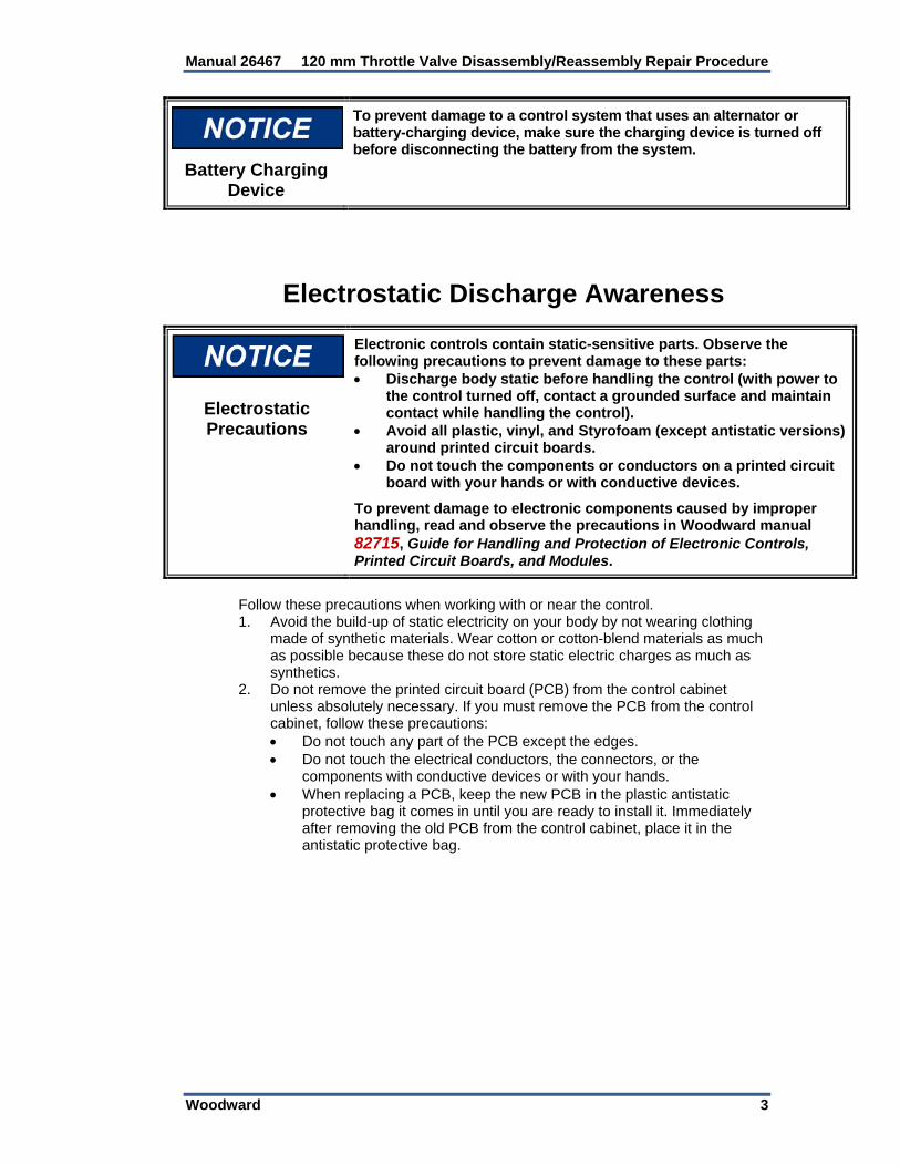
Battery Charging Device
To prevent damage to a control system that uses an alternator or battery-charging device, make sure the charging device is turned off before disconnecting the battery from the system.
Electrostatic Discharge Awareness
Electrostatic Precautions
Electronic controls contain static-sensitive parts. Observe the following precautions to prevent damage to these parts: Discharge body static before handling the control (with power to
the control turned off, contact a grounded surface and maintain contact while handling the control).
Avoid all plastic, vinyl, and Styrofoam (except antistatic versions) around printed circuit boards.
Do not touch the components or conductors on a printed circuit board with your hands or with conductive devices.
To prevent damage to electronic components caused by improper handling, read and observe the precautions in Woodward manual 82715, Guide for Handling and Protection of Electronic Controls, Printed Circuit Boards, and Modules.
Follow these precautions when working with or near the control. 1. Avoid the build-up of static electricity on your body by not wearing clothing
made of synthetic materials. Wear cotton or cotton-blend materials as much as possible because these do not store static electric charges as much as synthetics.
2. Do not remove the printed circuit board (PCB) from the control cabinet unless absolutely necessary. If you must remove the PCB from the control cabinet, follow these precautions:
Do not touch any part of the PCB except the edges. Do not touch the electrical conductors, the connectors, or the
components with conductive devices or with your hands. When replacing a PCB, keep the new PCB in the plastic antistatic
protective bag it comes in until you are ready to install it. Immediately after removing the old PCB from the control cabinet, place it in the antistatic protective bag.

120 mm Throttle Valve Disassembly/Reassembly Repair Procedure Manual 26467
4 Woodward
Chapter 1. 120 mm Throttle Valve with Actuator
Parts
Parts Description
1. Throttle Housing 2. Shaft/Housing Needle Bearing (6V-2830) 3. End Cap O-Ring (5P-5599) 4. End Cap 5. End Cap Screws (2) 6. Butterfly Plate Screws (3) (331-1698) 7. Butterfly Plate (331-2910) 8. Plug 9. Shaft (331-2905) 10. Flat Washers (4) 11. Nylok Nuts (4)
12. Screws (4) 13. Actuator 14. Shaft Coupler 15. Carrier Assembly (331-2904) 16. Carrier screws (2) 17. O-Ring 18. Washer (4) 19. O-Ring 20. Drive Screw (2) N/S 21. Nameplate N/S 22. O-Ring (2)
Figure 1-1. Parts Description

Manual 26467 120 mm Throttle Valve Disassembly/Reassembly Repair Procedure
Woodward 5
Chapter 2. 120 mm Throttle Valve with Actuator
Disassembly
Disassembly of Throttle Valve 1. Remove coupler plug (8) with ¼-inch hex bit. 2. Rotate the throttle plate to position bolts for access. Loosen the coupler bolt
with a 5 mm hex bit. 3. Remove four screws holding the actuator to the valve, use a 5 mm hex bit
and 10 mm box end wrench. 4. Separate the actuator from the valve body.
Figure 2-1. Disassembly of Throttle Valve

120 mm Throttle Valve Disassembly/Reassembly Repair Procedure Manual 26467
6 Woodward
5. Remove the three screws (6) holding the throttle plate (7). Use a 10 mm socket.
6. Remove end cap (4) with 5/32 inch hex, and remove O-ring (3). 7. Remove carrier assembly (15) with 3 mm hex bit. 8. Gently tap, with soft tool, the shaft out from end cap side. 9. Press out needle bearing on end cap, (tap from inside valve). 10. Change out required parts and reassemble per Chapter 3.
Figure 2-2. Disassembly of Throttle Valve

Manual 26467 120 mm Throttle Valve Disassembly/Reassembly Repair Procedure
Woodward 7
Chapter 3. 120 mm Throttle Valve with Actuator
Reassembly
Parts Preparation and Shaft / Throttle Housing Bearing Installation
1. If visibly dirty, wash the throttle housing (1) (before installing the needle
bearing), butterfly plate (7), end cap (4) and coupler (14). Do not use ultrasonics. Use an air gun to blow out the carrier assembly.
2. Using tool #1007-7403, press needle bearing (2), seal end first, into throttle
housing (1).
Figure 3-1. Installation of Shaft / Throttle Housing Bearing

120 mm Throttle Valve Disassembly/Reassembly Repair Procedure Manual 26467
8 Woodward
Install the Shaft and Butterfly Plate 1. With throttle housing (1) setting as shown, hold butterfly plate (7) inside the
throttle throat with the word “top” in the position shown. 2. Insert the bearing race end of shaft (9) into throttle housing (1) from left to
right, through butterfly plate (7) and into the needle bearing previously installed in the throttle housing.
The plate must be able to rotate as shown in the lower photo of Figure 3-2.
To ensure proper installation, note the position of the coupler screw access
port (1a) in relation to the word “TOP” on the butterfly plate. Do not secure the butterfly plate at this time.
Figure 3-2. Install the Shaft and Butterfly Plate

Manual 26467 120 mm Throttle Valve Disassembly/Reassembly Repair Procedure
Woodward 9
Install the Carrier Assembly 1. Apply a light film of petroleum jelly to O-ring (15a) and Glyd seal (15b).
Place carrier (15) over shaft (9) and gently push it down into place. Some resistance will come from Glyd seal (15b) slipping onto the shaft race and some from O-ring (15a) slipping into the housing counterbore.
2. Make sure carrier assembly (15) is completely seated, then apply one drop
Loctite 243 to screws (16) and secure the carrier to throttle housing (1). Torque the screws to 7.0 ±0.4 lb-in (0.79 ±0.05 Nm).
Figure 3-3. Install the Carrier Assembly

120 mm Throttle Valve Disassembly/Reassembly Repair Procedure Manual 26467
10 Woodward
Secure the Butterfly Plate and Install the End Cap 1. Install three screws (6) through butterfly plate (7) and start them into the
shaft. 2. To ensure butterfly plate (7) is properly located on the shaft (9) and in the
throttle throat, use your fingers to firmly close the side with the word “TOP” down several times to center it in the bore. A slight bind will be felt in the closed position. Hold it there while you tighten the center screw (6). Continue holding it in place and torque the three screws (6) to 72 ±4 lb-in (8.1 ±0.5 Nm).
3. Apply petroleum jelly to O-ring (3) and install it in the groove in throttle
housing (1). 4. Apply Loctite 242 to two screws (5). Secure end cap (4) to throttle housing
(1). Torque the screws (5) to 13.0 ±0.7 lb-in (1.47 ±0.08 Nm).
Figure 3-4. Secure the Butterfly Plate and Install the End Cap

Manual 26467 120 mm Throttle Valve Disassembly/Reassembly Repair Procedure
Woodward 11
Install the Coupler 1. Slide the wide section of coupler (14) on actuator shaft (13a) with the
screws (14a) & (14b) at the bottom as shown. Leave approximately a 0.070 inch (1.78 mm) gap between the coupler (14) and the actuator housing.
2. Tighten screw (14a) on the actuator side of coupler (14). Torque to 78 ±4
lb-in (8.8 ±0.5 Nm). Leave screw (14b) loose. 3. Install O-ring (17) on actuator (13). Apply a light film of petroleum jelly to the
O-ring.
Figure 3-5. Install the Coupler

120 mm Throttle Valve Disassembly/Reassembly Repair Procedure Manual 26467
12 Woodward
Attach the Actuator to the Throttle Housing 1. Determine if the actuator has a return spring by rotating the shaft. After
determination, do the following: a. With return spring: With butterfly plate (7) fully closed (CCW) and with
actuator (13) tilted slightly CCW, slide the coupler completely onto the throttle shaft until the actuator housing is against throttle housing flange (1a).
b. Without return spring: Turn butterfly plate (7) approximately 45° from the closed position. With actuator (13) tilted slightly CCW, slide the coupler completely onto the throttle shaft until the actuator housing is against throttle housing flange (1a).
2. Insert four screws (12)with flat washers (18) through the actuator housing
and the slotted holes in housing flange (1a). Secure but do not tighten with four flat washers (10) and four nylok nuts (11).
Figure 3-6. Attach the Actuator to the Throttle Housing

Manual 26467 120 mm Throttle Valve Disassembly/Reassembly Repair Procedure
Woodward 13
Set the Throttle Gap 1. Rotate actuator (13) CW until there is a 0.012 inch (0.30 mm) gap between
butterfly plate (7) and the throttle throat. If the flange slots do not allow enough rotation to establish the 0.012 inch (0.30 mm) gap, pull the coupler off the throttle shaft, rotate the actuator one serration CCW, and try again.
2. Also check to see that the valve can actuate from fully closed to fully open. If
not, rotate the actuator one serration and try again. 3. After achieving the 0.012 inch (0.30 mm) gap, tighten four nuts (11).
Recheck the gap. Using a cross-hatch pattern, torque the nuts to 12.0 ±0.6 lb-ft (16.3 ±0.8 Nm). Go back and recheck the torque a second time.
Figure 3-7. Set the Throttle Gap

120 mm Throttle Valve Disassembly/Reassembly Repair Procedure Manual 26467
14 Woodward
Tighten the Coupler and Install Access Port Plug and Nameplate
1. Insert an Allen wrench (A) through the coupling screw access port (1a) and
tighten the coupler screw on the throttle shaft side. Torque to 78 ±4 lb-in (). Re-check the gap at 0.012 inch (0.30 mm) and the butterfly plate for smooth rotation.
2. Install O-ring (19) on plug (8). Apply petroleum jelly and install it in access
port (1a). Turn it in tight.
Figure 3-8. Tighten the Coupler and Install Access Port Plug

We appreciate your comments about the content of our publications.
Send comments to: [email protected]
Please reference publication 26467.
PO Box 1519, Fort Collins CO 80522-1519, USA 1000 East Drake Road, Fort Collins CO 80525, USA Phone +1 (970) 482-5811 Fax +1 (970) 498-3058
Email and Website—www.woodward.com
Woodward has company-owned plants, subsidiaries, and branches, as well as authorized distributors and other authorized service and sales facilities throughout the world.
Complete address / phone / fax / email information for all locations is available on our website.
2013/4/Colorado