product line card 2017 - teledyne lecroy · spacewire • ethernet (10/100base-t) ... eye diagram...
TRANSCRIPT

Product Line Card 2017
NEWHV Fiber
Optically-isolated Probes
NEWHDO8000A
12-Bit, 8 Ch.,1 GHz,
10 GS/s
HDO900010-Bit, 4 GHz,
40 GS/s
NEWWaveSurfer 510
1 GHz at Great Price
NEWHDO4000A/
6000A12-Bit, 1 GHz, 10 GS/s with
OneTouch

DEBUG IN HIGH DEFINITION UP TO 4 GHz
High Defi nition Oscilloscopes with HD Technology have a variety of benefi ts that allow the user to debug with
unsurpassed precision. Waveforms displayed by High Defi nition Oscilloscopes are cleaner and crisper. More signal
details can be seen and measured; these measurements are made with unmatched precision resulting in better
test results and shorter debug time.
2
A critical element of the HDO9000 is the HD1024 technology, which provides 10 bits of vertical resolution with 4 GHz bandwidth. As with all members of Teledyne LeCroy’s HDO family, the HDO9000 utilizes an exceptionally low-noise system architecture that delivers outstanding effective number of bits (ENOB).
Dynamic ADC Reconfi guration
HD1024 technology enables dynamic reconfi guration of the ADCs to achieve 10 bits of vertical resolution. By auto-matically determining the best ADC confi guration under each specifi c measurement condition, the HDO9000 always provides the optimal resolution. The ADCs can be set to 8-, 9-, or 10-bit confi gurations.
HD Summary
The HDO9000 conveniently displays an overview of the HD1024 operation which can be accessed via the HD descriptor box.
Optimized Filtering
HD1024 high defi nition technology makes use of optimized fi ltering to provide additional resolution beyond 10-bits; extending up to 13.8 bits. When operating in low sample rate conditions, an anti-aliasing fi lter is automatically applied to reduce excess out-of-band noise. Additionally, resolution can be improved by applying a manual bandwidth limit on an individual channel.
HD4096 high defi nition technology consists of high sample rate 12-bit ADCs, high signal-to-noise ratio amplifi ers and a low-noise system architecture. This technology enables
High Defi nition Oscilloscopes to capture and display signals of up to 1 GHz, up to 10 GS/s sample rate and 16 times more resolution than other oscilloscopes.
HDO4000A HDO6000A HDO8000A HDO9000
HD Technology HD409612-Bits
HD409612-Bits
HD409612-Bits
HD102410-Bits
Bandwidth 200 MHz – 1 GHz 350 MHz – 1 GHz 350 MHz – 1 GHz 1 GHz – 4 GHz
Input Channels 4 4 8 4
Sample Rate 10 GS/s 10 GS/s 10 GS/s 40 GS/s
Analysis Capability Basic Advanced Advanced Exceptional

MAUI – SUPERIOR USER EXPERIENCE
3
MAUI – Most Advanced User Interface was developed to put all the power
and capabilities of the modern oscilloscope right at your fi ngertips.
Designed for touch; all important oscilloscope controls are accessed through
the intuitive touch screen user interface. Built for simplicity; time saving
shortcuts and intuitive dialogs simplify setup. Made to solve; a deep set of
debug and analysis tools helps identify problems and fi nd solutions quickly.
A
B
CDrag to quickly position cursors on a trace.
Confi gure parameters by touching measurement results.
Channel, timebase, and trigger descriptors provide easy access to controls without navigating menus.
Shortcuts to commonly used functions are displayed at the bottom of the channel, math and memory menus.
MAUI with OneTouch MAUI with OneTouch introduces a new paradigm for oscilloscope user experience. Dramatically reduce setup
time with revolutionary drag and drop actions to copy and setup channels, math functions, and measurement parameters without lifting a fi nger. Use common gestures like drag, drop, and flick to instinctively interact with the oscilloscope. Quickly enable a new
channel, math or measurement using the “Add New” button and simply turn off any trace or parameter with a flick of the fi nger. These OneTouch innovations provide unsurpassed effi ciency in oscilloscope operation.
E
D
F
G
B
C
DE
F
Use the “Add New” button for one-touch trace creation.
Drag to change source, copy setup, turn on new trace, or move waveform location.
Drag to copy measurement parameters to streamline setup process.
Unique to OneTouch
MAUI
A
G

POWERFUL, DEEP TOOLBOX
4
Our HeritageTeledyne LeCroy’s 50+ year heritage has its origins in the high-speed collection of data in the fi eld of high-energy physics, and the processing of long records to extract meaningful insight. We didn’t invent the oscilloscope, but we did invent the digital oscilloscope, which can take full advantage of advanced digital signal processing and waveshape analysis tools to provide unparalleled insight.
Our ObsessionOur developers are true to our heritage – they are more obsessed with making better and smarter tools than anybody else. Our tools and operating philosophy are standardized across much of our product line for a consistent user experience. Our mission is to help you use these tools to understand problems, including the ones you don’t even know you have. Our deep toolbox inspires insight; and your moment of insight is our reward.
Our Invitation Our Periodic Table of Oscilloscope Tools provides a framework to understand the toolsets that Teledyne LeCroy has created and deployed in our oscilloscopes. Visit our interactive website to learn more about what we offer and how we can help you develop and debug more effi ciently.
teledynelecroy.com/tools

MOST COMPLETE SERIAL DATA DEBUG AND VALIDATION
5
Embe
dded
C
ompu
ting
Aut
omot
ive
+ In
dust
rial
Avi
onic
sH
igh
Spe
ed C
ompu
ting,
S
tora
ge +
Per
iphe
rals
MIP
IO
ther
Serial DataProtocol Support
Mem
ory
Dec
ode
Trig
ger
Mea
sure
/Gra
phEy
e D
iagr
am
I2C • • • •
SPI • • • •
UART-RS232 • • • •
USB2-HSIC •
CAN • • • •
CAN FD • • • •
FlexRay • • • •
LIN • • • •
SENT •
MOST50/150 •
BroadR-Reach •
ARINC429 • • •
MIL-STD-1553 • • • •
SPACEWIRE •Ethernet (10/100Base-T)
• •
Ethernet (1000Base-T)
•
USB 1.1/2.0 • • • • • •
MD10 •
8b/10b • • •
Fibre Channel •
SATA (1.5 & 3 Gb/s) • • •
SAS (1.5 & 3 Gb/s) • •
PCI Express (Gen1) • •
LPDDR2 • •
DDR2 • •
DDR3 • •
D-PHY/CSI-2/DSI • • •
DigRF3G • •
DigRFv4 • •
UniPro •
M-PHY • •SPM •Audio (I²S, LJ, RJ, TDM) • • •
Manchester •
NRZ • • •
Pro
toS
ync
Qua
liPH
YMeasure/Graph
Quickly validate cause and effect with automated timing measurements to or from an analog signal or another serial message. Make multiple measurements in a single long acquisition to quickly acquire statistics during corner-case testing. Serial (digital) data can be extracted to an analog value and graphed to monitor system performance over time, as if it was probed directly. Complete validation faster and gain better insight.
Trigger
Powerful, flexible triggers designed by people who know the standards, with the unique capabilities you want to isolate unusual events. Conditional data triggering permits maximum flexibility and highly adaptable error frame triggering is available to isolate error conditions. Effi ciently acquire bursted data using Sequence Mode to maximize the oscilloscope's memory usage. Sequence Mode enables the oscilloscope to ignore idle time and acquire only data of interest.
Decode
Decoded protocol information is color-coded to specifi c portions of the serial data waveform and transparently overlaid for an intuitive, easy-to-understand visual record. All decoded protocols are displayed in a single time-interleaved table. Touch a row in the interactive table to quickly zoom to a packet of interest and select a column header to create fi lter criteria, as is commonly done in spreadsheets. Easily search through long records for specifi c protocol events using the built-in search feature.
Eye Diagram
Rapidly display an eye diagram of your packetized low-speed serial data signal without additional setup time. Use eye parameters to quantify system performance and apply a standard or custom mask to identify anomalies. Mask failures can be indicated and can force the scope into Stop mode.
SDAII or DDR Debug (optional) create eye diagrams of streaming NRZ serial data or DDR signals, and measure and analyze jitter breakdown.
CAN FD
UART
RS-232
USB2
i
SPI
I2C
T
U
FlexRayLIN
CAN
T D M E

10-BIT UP TO 4 GHz, 40 GS/s
HDO9000
Exceptional Signal Fidelity with 10-Bit Resolution
Key Features
● 10-bit resolution; up to 13.8-bit with Optimized Filtering
● 1 GHz – 4 GHz bandwidths
● Up to 40 GS/s sample rate
● 15.4” touch screen
● MAUI with OneTouch Gesture Control
● Advanced Tools› Jitter and Timing Analysis Capabilities› WaveScan – Search and Find› LabNotebook Documentation and Report Generation› History Mode – Waveform Playback
● 16 digital channels with 1.25 GS/s› Analog and Digital Cross-Pattern Triggering› Digital Pattern Search and Find› Analog and Digital Timing Measurements
● Optional Software Packages› Advanced Customization› Digital Filtering› Spectrum Analysis› Device and Switching Power Supply Analysis› Comprehensive set of serial data analysis, debug, validation and compliance tools
HDO9000 is providing the most advanced tools for debug and analysis of serial data.
6
HDO9000 High Defi nition Oscilloscopes leverage HD1024 technology to
deliver 10 bits of resolution up to 4 GHz. HD1024 technology ensures that
optimal resolution is always provided under each measurement condition
for exceptional signal fi delity. The large, bright 15.4” touch screen and
MAUI OneTouch user interface results in an unsurpassed user experience.
With 40 GS/s sample rate and an extensive toolbox the HDO9000 debugs
in high defi nition to provide uncompromised measurement performance.
HD1024 Technology
HD1024 high defi nition technology enables 10 bits of vertical resolution with 4 GHz bandwidth. The HDO9000 automatically and dynamically deter-mines the best ADC confi guration under each specifi c measurement condition to always provide the optimal resolution.
Dynamic ADC Reconfi guration
HD1024 technology enables dynamic reconfi guration of the ADC to achieve 10-bit vertical resolution. By auto-matically determining the best ADC confi guration under each specifi c mea-surement condition, the HDO9000 always provides the optimal resolution.
Powerful, Deep Toolbox
The standard collection of math, measurement, debug, and documen-tation tools provides unsurpassed analysis capabilities. Application- specifi c packages enable stream-lined debugging for common design/validation scenarios. The advanced customization option (XDEV) enables user-defi ned parameters and math functions providing unique and limitless analysis capability.
15.4” Capacitive Touch Screen
The HDO9000 and MAUI OneTouch allows users to perform all common operations with a single touch of the display, optimizing for convenience and effi ciency. Meanwhile, the 15.4” high resolution touch screen’s bright display and quick responsiveness further en-hances the effi ciency and intuitiveness of MAUI OneTouch.
Exceptional Serial Data Tools
A wide variety of application packages are available to meet all serial data test challenges, ranging from automated compliance packages to flexible debug toolkits. A suite of protocol specifi c measurement and eye diagram pack-ages are available to complement the industry’s most intuitive trigger and decode packages.

12-BIT 8 CHANNEL WITH UP TO 1 GHz
HDO8000A
HD 8-Channel Oscilloscopes up to 1 GHz, 10 GS/s
Key Features
● 8 analog channels
● 12-bit ADC resolution, up to 15-bit with enhanced resolution
● 350 MHz, 500 MHz, and 1 GHz bandwidths
● 10 GS/s Sample Rate
● Long memory – up to 250 Mpts/Ch
● 16 digital channel MSO option
● Q-Scape™ multi-tab display architecture
● 12.1" touch screen display with Super HD WQXGA 3840 x 2160 pixel extended-desktop mode
● MAUI with OneTouch Gesture Control
● Wide probe selection for power electronics, embedded electronics, and mechatronics applications
● Advanced analysis and reporting toolsets
● Advanced triggering supplemented with TriggerScan and measurement trigger
● Serial data trigger & decode and debug toolkit options
HDO8000A High Defi nition Oscilloscopes have more channels, more resolution, more bandwidth and more memory than any other midrange oscilloscope. Ideal for debugging and troubleshooting three-phase power electronics, auto-motive electronics, and embedded/mechatronic designs with high resolution sensor signals.Comprehensive digital logic (MSO), low-speed serial data trigger, decode and analysis toolsets, and the widest variety of probes and application packages complete the solution. Get the most intuitive long-memory analysis using the unique Q-Scape multi-tab display architecture.
True 12-Bit Technology
HD4096 high defi nition technology consists of 12-bit ADCs with 10 GS/s sample rates, high signal-to-noise (55dB) input amplifi ers and a low-noise system architecture. This technology enables high defi nition oscilloscopes to capture and display signals of up to 1 GHz with 16 times more resolution than conventional 8-bit oscilloscopes.
Long Memory
Capture large amounts of data with more precision using the 250 Mpts/Ch of acquisition memory. Zoom in for detail, use Roll Mode for extremely long time periods, or 10 GS/s for capturing fast transients and slow events together over longer periods than ever before possible.
Comprehensive Analysis Tools
HDO8000A has the most comprehen-sive trigger, decode, math, measure-ment, and application toolsets available.
Use tracks, trends and histograms to enhance understanding of complex behaviors. LabNotebook concisely documents and stores your results.
Q-Scape Multi-Tab Display Architecture
More waveforms requires new display architectures. Unique Q-Scape multi -Tab display architecture speeds the under-standing of your design with 4x the display area. Quickly move waveforms to different tabs through drag-and-drop. Extended desktop supports WQXGA 3840 x 2160 pixel displays.
Powerful Analysis Capabilities
Up to 250 Mpts/Ch of acquisition memory allows many seconds of data capture. Display simultaneously up to 40 waveforms (12 math, 12 zoom, 12 memory) and 12 measurement parameters.
Tab 1
Tab 2
Tab 3
Tab 4
NEW
7

12-BIT 8 CHANNEL MOTOR DRIVE ANALYSIS
MDA800A Series
Motor Drive Analyzers
Motor Drive Analyzers provide complete three-phase
power analysis from motor drive input through motor
mechanical output, with results in a convenient numeric
table format. Motor speed, position, and torque integration
are the most complete available. Long memory, per-cycle
“ synthesized” Waveforms and Zoom+Gate mode provide
powerful dynamic drive and motor analysis. 8 analog
input channels (MSO optional) with high resolution
of 12 bits, sample rate up to 10 GS/s, bandwidth
up to 1 GHz and memory up to 250 Mpt/Ch provide
unique capability to perform complete system debug on the
motor drive power section, motor mechanical performance,
and embedded drive control system operation.
Key Features
● Complete Motor Drive SystemDebug and Validation inOne Instrument
● Three-Phase Power Measurements;Real, Apparent, Reactive Power
● Effi ciency Measurements
● User-Confi gurable Power Table
● Two- and Three-Wattmeter Methods supported
● Per-Cycle Time-CorrelatedWaveforms From Power Values
● Harmonics Calculations and Filtering (optional)
● Dynamic Drive Response Analysis,From Startup To Overload
● Unique Zoom+Gate Mode
● Line-Line To Line-Neutral VoltageConversion
● Up to 6000 VRMS Isolation with HVD Series Differential Probes
● Easily Interface OtherCurrent Measurement Devices
● Complete Motor Integration(Torque, Speed, Position)
● Flexible Setup Capability
● Graphical User Interface
Complete Drive System Debug
The Motor Drive Analyzer acquires drive power section, power transistor, and embedded control system signals, and performs three-phase power analysis of the power section waveforms.Correlation of drive system behaviors to embedded control loop signals enables debug and analysis of all aspects of the complete motor drive.
Numerics Measurement Table
Various voltage, current, power (real, apparent, and reactive), phase angle/power factor, and effi ciency parameters are calculated on acquired voltage and current waveforms and displayed in a table. The table is displayed along with the acquisition waveforms.
Zoom+Gate Dynamic Analysis
Capture long acquisitions and Zoom+Gate with instant table value updates and views of dynamic three-phase power and motor drive performance.
Most Complete MotorMechanical Integration
Simple integration is provided for nearly any type of speed, rotation or position sensor, including analog and
digital (pulse) tachometers, Brushless DC (BLDC) Hall sensor, Quadrature Encoder Interface (QEI), and Resolvers. Additionally, Hall sensor and QEI signals can be integrated through digital inputs, preserving valuable analog input channels for other signals.
Detailed Waveforms
In addition to the mean table values, a waveform showing any per-cycle measurement parameter variation can be displayed by simply selecting a table value. This waveform is time-correlated with other waveforms acquired by the MDA800A oscilloscope and can be used to correlate complex drive beha-viors to other control or power system waveforms, and to debug drive system problems. Statistical detail of the mea-surement set can also be displayed. This additional information goes well beyond what is provided by a Power Analyzer.
NEW
8
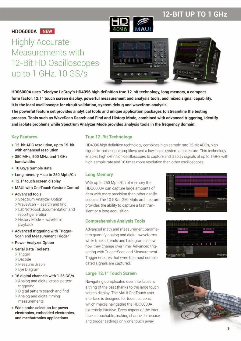
HDO6000A
Highly Accurate Measurements with 12-Bit HD Oscilloscopes up to 1 GHz, 10 GS/s
HD06000A uses Teledyne LeCroy’s HD4096 high defi nition true 12-bit technology, long memory, a compact
form factor, 12.1” touch screen display, powerful measurement and analysis tools, and mixed signal capability.
It is the ideal oscilloscope for circuit validation, system debug and waveform analysis.
The powerful feature set provides analytical tools and unique application packages to streamline the testing
process. Tools such as WaveScan Search and Find and History Mode, combined with advanced triggering, identify
and isolate problems while Spectrum Analyzer Mode provides analysis tools in the frequency domain.
Key Features
● 12-bit ADC resolution, up to 15-bit with enhanced resolution
● 350 MHz, 500 MHz, and 1 GHz bandwidths
● 10 GS/s Sample Rate
● Long memory – up to 250 Mpts/Ch
● 12.1” touch screen display
● MAUI with OneTouch Gesture Control
● Advanced tools› Spectrum Analyzer Option› WaveScan – search and fi nd› LabNotebook documentation and report generation› History Mode – waveform playback
● Advanced triggering with Trigger-Scan and Measurement Trigger
● Power Analyzer Option
● Serial Data Toolsets› Trigger› Decode› Measure/Graph› Eye Diagram
● 16 digital channels with 1.25 GS/s› Analog and digital cross-pattern triggering› Digital pattern search and fi nd› Analog and digital timing measurements
● Wide probe selection for powerelectronics, embedded electronics,and mechatronics applications
True 12-Bit Technology
HD4096 high defi nition technology combines high sample rate 12-bit ADCs, high signal-to-noise input amplifi ers and a low-noise system architecture. This technology enables high defi nition oscilloscopes to capture and display signals of up to 1 GHz with high sample rate and 16 times more resolution than other oscilloscopes.
Long Memory
With up to 250 Mpts/Ch of memory the HDO6000A can capture large amounts of data with more precision than other oscillo-scopes. The 10 GS/s, 250 Mpts architecture provides the ability to capture a fast tran-sient or a long acquisition.
Comprehensive Analysis Tools
Advanced math and measurement parame-ters quantify analog and digital waveforms while tracks, trends and histograms show how they change over time. Advanced trig-gering with TriggerScan and Measurement Trigger ensures that even the most compli-cated signals are captured.
Large 12.1" Touch Screen
Navigating complicated user interfaces is a thing of the past thanks to the large touch screen display. The MAUI OneTouch user interface is designed for touch screens, which makes navigating the HDO6000A extremely intuitive. Every aspect of the inter-face is touch able, making channel, timebase and trigger settings only one touch away.
12-BIT UP TO 1 GHz
NEW
9

12-BIT UP TO 1 GHz
HDO4000A
Low Noise Measurements with True 12-Bit in HD up to 1 GHz, 10 GS/s
Combining HD4096 high defi nition technology with long memory, a compact
form factor, 12.1” touch screen display, powerful debug tools, and mixed
signal capability, the HDO4000A is the ideal oscilloscope for precise measure-
ments and fast debugging. Tools such as WaveScan Search and Find,
LabNotebook Report Generator, and History Mode help to identify and to
isolate problems for faster troubleshooting.
Key Features
● 12-bit ADC resolution, up to 15-bit with enhanced resolution
● 200 MHz, 350 MHz, 500 MHz, 1 GHz bandwidths
● 10 GS/s Sample Rate ● Long memory – up to 50 Mpts ● 12.1” touch screen display ● MAUI with OneTouch› Designed for touch› Built for simplicity› Made to solve
● Multi-language user interface ● WaveScan – search and fi nd ● LabNotebook documentation and report generation
● History Mode ● Spectrum Analyzer Option ● Power Analysis Option ● Serial data trigger and decode ● 16 digital channels with 1.25 GS/s› Analog and digital cross-pattern triggering› Digital pattern search and fi nd› Analog and digital timing measurements› Activity indicatorsable, making channel, timebase and
trigger settings only one touch away.
Compact Form Factor
The HDO4000A builds upon Teledyne LeCroy’s history of “Large Screen, Small Footprint” with its 12.1” wide touch screen display and a depth of only 5”. Additionally, the innovative rotating, tilting feet enable the HDO4000A to be placed in 4 different viewing positions ensuring optimal viewing no matter where it is being positioned in the lab.
Long Acquisition Window
With up to 50 Mpts of memory the HDO4000A High Defi nition Oscilloscopes can capture large amounts of data with more precision than other oscilloscopes. The 10 GS/s, 50 Mpts architecture provides the ability to capture a fast transient or a long acquisition.
Large 12.1" Touch Screen
Navigating complicated user interfaces is a thing of the past thanks to the large touch screen display. The MAUI OneTouch user interface is designed for touch screens which makes navigat-ing the HDO4000A extremely intuitive. Every aspect of the interface is touch-
8-bit 12-bitA A
B BCC
A Clean, Crisp Waveforms | Thin traces show the actual waveform with minimal noise interference
C Unmatched Measurement Precision | Measurements are more precise and not affected by quantization noise
B More Signal Details | Waveform details lost on an 8-bit oscilloscope can now be clearly seen
NEW
True 12-Bit Technology
HD4096 high defi nition technology con-sists of high sample rate 12-bit ADCs, high signal-to-noise input amplifi ers and a low-noise system architecture. This technology enables high defi nition oscilloscopes to capture and display signals of up to 1 GHz with high sample rate and 16 times more resolution than other oscilloscopes.
10

20 GHz – 100 GHz
The Fastest Oscilloscope for the Most Demanding Signals
Whether working on communications technology capable of terabit/s symbol rates, analyzing the quickest and most energetic laser pulses, or building links using very high speed NRZ or PAM4 signals, the LabMaster 10 Zi-A Series oscilloscopes can acquire and analyze the waveforms.
Sophisticated Software forSophisticated Analysis
The LabMaster 10 Zi-A Series offers an extensive set of standard math tools and add-on software packages that
integrate seamlessly into the oscillo-scope’s MAUI User Interface. LabMaster 10 Zi-A oscilloscopes excel at perform-ing in-depth analysis of complicated signals. For NRZ signals, the SDAIII- CompleteLinQ package compares eye, jitter and noise on up to four lanes simultaneously. With the Optical-LinQ package, analyze coherent optical signals such as DP-QPSK, DP-16QAM. Additionally, the PAM4 Signal Analysis package performs eye, jitter and noise measurements on PAM4 signals. Since the fastest signals often require custom analysis, LabMaster 10 Zi-A also comes standard with the ability to run MATLAB scripts in-stream.
LabMaster 10 Zi-A
World’s Highest BandwidthReal-Time Oscilloscope100 GHz, 240 GS/s
Key Features
● Up to 100 GHz bandwidth, 240 GS/s sample rate, 80 Ch, 1.5 Gpts/Ch of analysis memory
● Modular – start with four channels and expand your system over time
● Wide bandwidth upgrade range provides investment protection
● Single trigger circuit for all modules eliminates additive trigger jitter
● Simple – connect and acquire – Teledyne LeCroy has done the hard work for you
● 15.3″ widescreen touch screen display – or external monitor with up to WQXGA 2560 x 1600 pixels
● Highly stable timebase over long acquisitions, low jitter and Rj noise floor
● Eye Doctor™ II and Virtual Probe Signal Integrity toolsets provide real-time de-embedding, emulation, and equalization on serial data channels
● Seamless MATLAB analysis – Run custom scripts in real-time
● Superior Analysis Capabilities › Eye, Jitter and Noise Analysis with SDAIII-CompleteLinQ › Optical Modulation Analysis with Optical-LinQ
PAM4 signaling is seen as the next step in the evolution of serial data signal formats, allowing two bits of information to be transmitted per UI rather than one.
The LabMaster 10 Zi-A series of real-time oscilloscopes boasts the world’s
highest bandwidh and fastest sampling rate at 100 GHz and 240 GS/s. This
world-leading performance is key to acquiring, analyzing and understanding
the fastest phenomena found in R&D labs, where engineers are working
on next-generation communication systems, high bandwidth electrical
components and fundamental scientifi c research.
The Most Powerful, Flexible Optical Toolset
Teledyne LeCroy offers the most complete set of tools available for the development of leading-edge optical communications systems and components. The highest-bandwidth oscilloscopes, highest-performance optical modulation analyzers, and most flexible integrated software enable faster development and reduced time-to-market.
11

WaveMaster 8 Zi-B
Exceptional Performance up to 30 GHz, 80 GS/s
4 GHz – 30 GHz
Key Features ● Up to 30 GHz bandwidth, 80 GS/s sample rate, 512 Mpts/Ch of analysis memory
● The industry’s only true hardware 14.1 Gb/s serial pattern trigger
● Low Jitter Measurement Floor and exceptional timebase stability
● Comprehensive set of serial data analysis, debug, validation and compliance tools
● Integrated 50 Ω and 1 MΩ inputs for true connection and probing flexibility
● Multi-lane serial data eye, jitter and crosstalk analysis
● Real-time de-embedding, emulation, and equalization
● 15.3” touch screen display
18 Digital Channels at 12.5 GS/s
HDA125
High-Speed Mixed Signal Testing
Key Features
● 12.5 GS/s sampling rate for 80 ps timing accuracy
● 3 GHz leadset for capturing digital signals up to 6 Gb/s
● Unique QuickLink probing system› Easy access to diffi cult test points with differential solder-in tips with 9-inch lead› Ultra low loading for superior performance› Unmatched acquisition flexibility
.5 GS/s
WaveMaster 8 Zi-B combines high bandwidth and high sample rate with
superior signal fi delity performance and 20 GHz on all four input channels.
Availability of models from 4 to 30 GHz with complete bandwidth
upgradability throughout the entire product range makes it easy and
affordable to stay current with emerging high-speed technologies and
serial data standards.
The HDA125 transforms your oscillo scope into the highest- performance,
most flexible mixed-signal solution for high-speed digital debug and
evaluation. With 12.5 GS/s digital sampling rate on 18 input channels, and
the revolutionary QuickLink probing solution allowing seamless transitions
from digital to high-bandwidth analog acquisitions, validation of challenging
interfaces such as DDR4 has never been simpler or more comprehensive.
12

500 MHz – 4 GHz
WaveRunner 8000
Extremely Powerful. Incredibly Easy.
The WaveRunner 8000 combines a superior oscilloscope experience with
an extensive toolbox to shorten debug time. MAUI with OneTouch includes
the most unique touch features on any oscilloscope providing unsurpassed
effi ciency in oscilloscope operation. Offering 500 MHz – 4 GHz of bandwidth,
40 GS/s sample rate, long memory, MAUI – Most Advanced User Interface,
and a versatile toolset make the WaveRunner 8000 unbelievably powerful
and incredibly easy to use.
Key Features
● 500 MHz – 4 GHz bandwidths
● Up to 40 GS/s sample rate
● up to 128 Mpts/Ch of analysis memory
● 12.1” touch screen display
● MAUI with OneTouch› Designed for touch› Built for simplicity› Made to solve
● Advanced Tools› Jitter and Timing Analysis Capabilities› WaveScan – Search and Find› LabNotebook Documentation and Report Generation› History Mode – Waveform Playback
● Optional Software Packages› Advanced Customization› Digital Filtering› Spectrum Analysis› Device and Switching Power
● Supply Analysis› Comprehensive set of serial data analysis, debug, validation and compliance tools
● 16 digital channels with 1.25 GS/s› Analog and Digital Cross-Pattern Triggering› Digital Pattern Search and Find› Analog and Digital Timing Measurements› Logic Gate Emulation› Activity Indicators
WaveRunner 8000 combines a superior oscilloscope experie
extensive toolbox to shorten debug time. MAUI with OneTouc
Superior User Experience
The WaveRunner 8000 with MAUI OneTouch sets the standard for oscillo-scope user experience by providing the most unique touch features on any oscilloscope. Common gestures are used to instinctively interact with the oscilloscope and dramatically reduce setup time. Convenience and effi ciency are optimized – all common operations can be performed with one touch and do not require opening and closing of pop-up dialogs or menus.
Exceptional Serial Data Tools
A wide variety of application packages are available to meet all serial data test challenges, ranging from automated compliance packages to flexible debug toolkits. A suite of protocol specifi c measurements and eye diagram pack-ages are available to complement the industry’s most intuitive trigger and decode packages.
Powerful, Deep Toolbox
The standard collection of math, mea-surement, debug, and documentation tools provides unsurpassed analysis capabilities. Application-specifi c pack-ages enable streamlined debugging for common design/validation scenarios. The advanced customization option (XDEV) enables user-defi ned parame-ters and math functions providing unique and limitless analysis capability.
WaveRunner 8000 combines Serial Bus Trigger, Decode, Measure/Graph, and now also Eye Diagrams
13

1 GHz
WaveSurfer 510
1 GHz Oscilloscope
The WaveSurfer 510 combines the MAUI
with OneTouch user interface with powerful
waveform processing, in addition to advanced
math, measurement, and debug tools, to
quickly analyze and fi nd the root cause of
problems. The 12.1” touch-screen display of
the WaveSurfer 510 is the largest in its class
and makes viewing waveform abnormalities
fast and easy.
Key Features
● 1 GHz, 10 GS/s, up to 16 Mpts/ch
● MAUI – advanced user interface› Designed for touch › Built to simplify › Made to solve
● WaveScan – Advanced Search and Find
● LabNotebook Documentation and Report Generation
● History Mode – Waveform Playback
● Sequence Mode Segmented Memory
● Spectrum Analyzer Mode
● Power Analysis Software
● Serial Trigger and Decode› I2C, SPI, UART› CAN, LIN, FlexRay, SENT› Ethernet 10/100BaseT, USB 1.0/1.1/2.0, USB 2.0-HSIC› Audio (I2S, LJ, RJ, TDM)› MIL-STD-1553, ARINC 429› MIPI D-PHY, DigRF 3G, DigRF v4› Manchester, NRZ
cope
the MAUI
with powerful
on to advanced
g tools, to
ot cause of
een display of
est in its class
abnormalities
Key Features
Superior User Experience
The WaveSurfer 510 with MAUI OneTouch sets the standard for oscillo-scope user experience by providing the most unique touch features on any oscillo scope. Common gestures are used to instinctively interact with the oscilloscope and dramatically reduce setup time. Convenience and effi ciency are optimized – all common operations can be performed with one touch and do not require opening and closing of pop-up dialogs or menus.
Uncompromised Performance
Many 1 GHz oscilloscopes are available at attractive entry-point prices, how-ever, they are often limited in sample rate, memory or features. The Wave-Surfer 510 provides uncompromised 1 GHz performance with up to 10 GS/s per channel and 32 Mpts of memory.
Advanced Debug Tools
Advanced debug tools make the Wave-Surfer 510 an unparalleled debug and analysis machine providing 10 GS/s sample rate on 4 channels, 32 Mpts of memory, sequence mode, history mode, advanced math functions, and 2 simul-taneous math traces.
Capture Debug, Analyze, Document
Easily accessible measurement, math and debug tools, plus a wide variety of serial data protocol decoders, and active probes ensure the WaveSurfer 510 can capture and analyze any type of wave-form and simplify the debug process. The LabNotebook tool provides a fast way to save waveforms, save setups and screen images, report results, and view offline.
14

200 MHz – 750 MHz
WaveSurfer 3000
Designed to Touch, Built for Simplicity, Made to Solve WaveSurfer 3000 oscilloscopes feature the MAUI advanced
user interface with touch screen simplicity to shorten debug
time. Quickly identify and isolate anomalies with WaveScan,
Fast Display, and History Mode for faster troubleshooting;
LabNotebook enables easy documentation and convenient
collaboration. The advanced probe interface, upgradable
bandwidth and multi-instrument capabilities provide maxi-
mum versatility and investment protection.
Key Features
● 200 MHz, 350 MHz, 500, and 750 MHz bandwidths
● Up to 4 GS/s sample rate
● Long memory – 10 Mpts/Ch
● 10.1” touch screen display
● MAUI – advanced user interface› Designed for touch › Built to simplify › Made to solve
● Advanced anomaly detection› Fast waveform update › History Mode › WaveScan
● Superior toolset› LabNotebook › Sequence Mode › Advanced active probe interface › Math and measure
● Multi-instrument capabilities› Protocol analysis – Serial trigger and decode I2C, SPI, UART/RS-232, CAN, CAN FD, LIN, FlexRay› Waveform generation – built-in arbitrary generator › Digital Voltmeter DVM› Logic analysis – 16 channel MSO
● Future proof› Upgradeable bandwidth› Field upgradable software and hardware options
or
dvanced
en debug
aveScan,
ooting;
venient
dable
e maxi-
MAUI – A New Wave of Thinking
MAUI advanced user interface is designed for touch. All important con-trols are accessed through the intuitive touch control. MAUI is made for simplic-ity; time saving shortcuts and intuitive dialogs simplify setup. MAUI is built to solve. A deep set of debug and analysis tools help identify problems and fi nd solutions quickly.
Advanced Anomaly Detection
Combining a fast waveform update rate of 130,000 waveforms/second with History mode waveform playback-and WaveScan search and fi nd, the WaveSurfer 3000 is an outstanding tool for waveform anomaly detection.
Capture, Debug, Analyze, Document
The advanced active probe interface gives tremendous flexibility for captur-ing all types of signals. Debug, analyze and document problems through the use of powerful math and measurement capabilities, sequence mode segmented memory, and LabNotebook.
Multi-Instrument Capabilities
Beyond traditional oscilloscope function-ality the WaveSurfer 3000 has a variety of multi-instrument capabilities including waveform generation with a built-in arbitrary generator, a digital voltmeter DVM, protocol analysis with serial data trigger and decode, and logic analysis with a 16 channel mixed signal option.
W
W
t
15

OSCILLOSCOPES
LabMaster 10 Zi-A(SDA/DDA Models)
WaveMaster 8 Zi-B(SDA/DDA 8 Zi-B)
WavePro 7 Zi-A(SDA/DDA 7 Zi-A)
Classifi cation Modular High End Analysis
High End Analysis High End Analysis
Bandwidth 20 GHz to 100 GHz 4 GHz to 30 GHz 1.5 GHz to 6 GHz
Resolution 8-bit ADC resolution, 11-bit with ERES
8-bit ADC resolution, 11-bit with ERES
8-bit ADC resolution, 11-bit with ERES
Channels Up to 80 4 4
MSO Characteristics – 18/36 Ch Low Speed 1)
9/18 Ch High Speed 4)
18/36 Ch Low Speed 1)
9/18 Ch High Speed 4)
Display 15.3" WXGA Color Touch Screen 15.3" WXGA Color Touch Screen 15.3” WXGA Color Touch Screen
Memory 32 Mpts/Ch to 1.5 Gpts/Ch 64 Mpts to 512 Mpts/Ch 32 Mpts/Ch to 256 Mpts/Ch
Sample Rate Up to 240 GS/s Up to 80 GS/s Up to 40 GS/s
Trigger Types Basic, SMART, Sequence, High Speed Serial Protocol,
Measurement
Basic, SMART, Sequence, High Speed Serial Protocol,
Measurement
Basic, SMART, Sequence, High Speed Serial Protocol,
Measurement
Serial Data Options 37 37 37
Dimensions (HWD) MCM-Zi: 277 x 462 x 396 mmLabMaster 10-xxZi Acq. Module:
202 x 462 x 660 mm
355 x 467 x 406 mm 355 x 467 x 289 mm
HDO4000A/HDO4000A-MS WaveSurfer 510 WaveSurfer 3000
Classifi cation High Defi nition Analysis Bench Bench
Bandwidth 200 MHz to 1 GHz 1 GHz 200 MHz – 750 MHz
Resolution 12-bit ADC resolution, 15-bit with ERES
8-bit ADC resolution, 11-bit with ERES
8-bit ADC resolution,11-bit with ERES
Channels 4 4 2 / 4
MSO Characteristics 16 Ch 2) 18 Ch or 36 Ch 1) 16 Ch 3)
Display 12.1” WXGA Color Touch Screen 12.1” WXGA Color Touch Screen 10.1” Color Touch Screen
Memory 25 Mpts/Ch to 50 Mpts/Ch 16 Mpts/Ch to 32 Mpts/Ch 10 Mpts/Ch
Sample Rate 10 GS/s (12-bit) 10 GS/s Up to 4 GS/s
Trigger Types Basic, SMART, Sequence Basic, SMART, Sequence Basic, SMART, Sequence
Serial Data Options 23 23 6
Dimensions (HWD) 291 x 399 x 131 mm 316 x 417 x 238 mm 220 x 350 x 145 mm
1) 18/36 Digital Channels with MS-250/500 Options 2) MS Models 3) 16 Digital Channels with MS-Option 4) HDA125 Option
16

Learn More: teledynelecroy.com/oscilloscope
WaveRunner 8000 HDO9000HDO8000A/MDA800A
HDO6000A/HDO6000A-MS
Advanced Analysis
Advanced High Defi nition Analysis
8-Channel High Defi nition Analysis
Advanced High Defi nition Analysis
500 MHz to 4 GHz 1 GHz to 4 GHz 350 MHz to 1 GHz 350 MHz to 1 GHz
8-bit ADC resolution, 11-bit with ERES
10-bit ADC resolution,up to 13.8-bit with optimized fi ltering
12-bit ADC resolution, 15-bit with ERES
12-bit ADC resolution, 15-bit with ERES
4 4 8 4
16 Ch 3) 16 Ch 3)
9/18 Ch High Speed 4)
16 Ch 3) 16 Ch 2)
12.1” WXGA Color Touch Screen 15.4” WXGA Color Touch Screen 12.1” WXGA Color Touch Screen 12.1” WXGA Color Touch Screen
32 Mpts/Ch to 128 Mpts/Ch 128 Mpts/Ch 50 Mpts/Ch to 250 Mpts/Ch 50 Mpts/Ch to 250 Mpts/Ch
Up to 40 GS/s Up to 40 GS/s 10 GS/s (12-bit) 10 GS/s (12-bit)
Basic, SMART, Sequence, Measurement
Basic, SMART, Sequence, Measurement
Basic, SMART, Sequence, Measurement
Basic, SMART, Sequence, Measurement
37 37 24 24
316 x 417 x 238 mm 358 x 445 x 242 mm 374 x 417 x 280 mm 291 x 399 x 131 mm
WaveJet Touch
Bench
350 MHz to 500 MHz
8-bit ADC resolution
4
–
7.5" Color Touch Screen
5 Mpts/Ch
2 GS/s
Standard
3
190 x 295 x 102 mm
HDO6000A/HDO6000A-MS
Powerful Mixed Signal Test Solutions
MSO-Models
16 Channel, 1.25 GS/s Mixed Signal probe and accessories for the following oscilloscope series:
HDO4000A, HDO6000A, HDO8000A/MDA800A, HDO9000, WR8000, WS3000
MS-250/500
18/36 Channel, 2 GS/s Mixed Signal Oscilloscope Option for the following oscilloscope series:
WM8Zi-B, WP7Zi-A, WR6Zi, HDO9000, WS510
HDA125
12.5 GS/s High-Speed Digital Analyzer with 18 ch QuickLink leadset for the following oscilloscope series:
WM8Zi-B, WP7Zi-A, WR6Zi, HDO9000
17

OSCILLOSCOPE PROBESOSCILLOSCOPE PROBES
Passive Probes
PP006A 500 MHz, 10:1, 10 MΩ, 600 V Passive ProbePP007 500 MHz, 10:1, 10 MΩ, 400 V Passive ProbePP008 500 MHz, 10:1, 10 MΩ, 400 V Passive ProbePP009 500 MHz, 10:1, 10 MΩ, 400 V Passive Probe PP010 200 MHz, 10:1, 10 MΩ, 600 V Passive ProbePP011 500 MHz, 10:1, 10 MΩ, 400 V Passive ProbePP017 250 MHz, 10:1, 10 MΩ, 600 V Passive ProbePP018 500 MHz, 10:1, 10 MΩ, 600 V Passive ProbePP019 250 MHz, 10:1, 10 MΩ, 500 V Passive ProbePP020 500 MHz, 10:1, 10 MΩ, 500 V Passive ProbePP021 500 MHz, 10:1, 10 MΩ, 500 V Passive ProbePP022 500 MHz, 10:1, 10 MΩ, 500 V Passive ProbePP023 500 MHz, 10:1, 10 MΩ, 500 V Passive ProbePP024 500 MHz, 10:1, 10 MΩ, 500 V Passive ProbePP025 500 MHz, 10:1, 10 MΩ, 500 V Passive ProbePP026 500 MHz, 10:1, 10 MΩ, 500 V Passive Probe
Wav
eJet
Wav
eSur
fer
HD
OW
aveR
unne
rW
aveP
roW
aveM
aste
rLa
bMas
ter
■
■ ■ ■ ■ ■
■ ■
■ ■
■
■ ■ ■ ■
■
■
■
■
■ ■ ■
■ ■
■ ■
■ ■
■ ■ ■ ■
■
Teledyne LeCroy passive probes automat-ically scale the oscilloscope waveforms without user input. Passive probes are the ideal tool for low frequency signals since circuit loading at these frequencies is minimized. Passive probes are designed to handle voltages of up to 400 V, some as high as 600 V.
ZS Series High Impedance Active Probes
ZS1000 1 GHz, 0.9 pF, 1 MΩ Active Voltage ProbeZS1500 1.5 GHz, 0.9 pF, 1 MΩ Active Voltage ProbeZS2500 2.5 GHz, 0.9 pF, 1 MΩ Active Voltage ProbeZS4000 4 GHz, 0.9 pF, 1 MΩ Active Voltage Probe
Wav
eJet
Wav
eSur
fer
HD
OW
aveR
unne
rW
aveP
roW
aveM
aste
rLa
bMas
ter
■ ■ ■ ■ ■ ■
■ ■ ■ ■ ■ ■
■ ■ ■ ■ ■ ■
■ ■ ■ ■ ■ ■
The ZS Series probes provide high imped-ance and an extensive set of probe tips and accessories to handle a wide range of probing scenarios. The high 1 MΩ input resistance and low 0.9 pF input capaci-tance mean this probe is ideal for all frequencies.
Current Probes
CP030A 30A; 50 MHz High Sensitivity Current Probe – AC/DC; 30 A rms; 50 A Peak Pulse
CP030 30 A; 50 MHz Current Probe – AC/DC; 30 A rms; 50 A Peak Pulse
CP031A 30A; 100 MHz High Sensitivity Current Probe – AC/DC; 30 A rms; 50 A Peak Pulse
CP031 30 A; 100 MHz Current Probe – AC/DC; 30 A rms; 50 A Peak Pulse
CP150 150 A, 10 MHz Current Probe – AC/DC; 150 A rms, 500 A Peak Pulse
CP500 500 A, 2 MHz Current Probe – AC/DC; 500 A rms, 700 A Peak Pulse
Wav
eJet
Wav
eSur
fer
HD
OW
aveR
unne
rW
aveP
roW
aveM
aste
rLa
bMas
ter
■ ■ ■ ■ ■ ■
■ ■ ■ ■ ■ ■
■ ■ ■ ■ ■ ■
■ ■ ■ ■ ■ ■
■ ■ ■ ■ ■ ■
■ ■ ■ ■ ■ ■
Available current probes reach bandwidths of 100 MHz, peak currents of 700 A and sensitivities of 1 mA/div. Use multiple current probes to make measurements on three phase systems or a single current probe with a voltage probe to make instantaneous power measurements.
Differential Probes
ZD200 200 MHz, 3.5 pF, 1 MΩ Active Differential Probe, ±20 V
ZD500 500 MHz, 1.0 pF Active Differential Probe, ±8 VZD1000 1 GHz, 1.0 pF Active Differential Probe, ±8 VZD1500 1.5 GHz, 1.0 pF Active Differential Probe, ±8 V
Wav
eJet
Wav
eSur
fer
HD
OW
aveR
unne
rW
aveP
roW
aveM
aste
rLa
bMas
ter
■ ■ ■ ■ ■ ■
■ ■ ■ ■ ■ ■
■ ■ ■ ■ ■ ■
■ ■ ■ ■ ■ ■
High bandwidth, excellent common-mode rejection ratio (CMRR) and low noise make these active differential probes ideal for applications such as automotive devel-opment (e.g. CAN) and failure analysis, as well as wireless and data communication design.
Active Voltage/Power Rail Probe NEW
RP4030 4 GHz bandwidth, 1.2x attenuation, ±30 V offset, ±800 mV
Wav
eJet
Wav
eSur
fer
HD
OW
aveR
unne
rW
aveP
roW
aveM
aste
rLa
bMas
ter
■ ■ ■ ■ ■ ■
Specifi cally designed to probe a low impedance power/voltage rail. The RP4030 has 30 V built-in offset adjust, low attenuation (noise), and high DC input impedance with 4 GHz of bandwidth and a wide assortment of tips and leads, including solder-in and U.FL receptacle connections.
Highlight – High sensitivity current probes for accurate measurements down to 1 mA/div
The right probe is essential for accurate signal capture. Teledyne LeCroy offers an extensive range of probes to meet virtually every probing need.
18

Learn More: teledynelecroy.com/probes
High Voltage Fiber Optically-Isolated Probe NEW
HVFO103 60 MHz, Superior Noise and Rejection (140 dB CMRR)
Wav
eJet
Wav
eSur
fer
HD
OW
aveR
unne
rW
aveP
roW
aveM
aste
rLa
bMas
ter
■ ■ ■ ■ ■ ■
The HVFO103 is a compact, simple, affordable probe for measurement of small signals (gate-drives, sensors, etc.) floating on an HV bus in power electronics designs, or for EMC, EFT, ESD, and RF immunity testing sensor monitoring. Suitable for up to 35 kV common-mode. 140 dB CMRR.
High Voltage Differential Probes
ADP300 20 MHz High-Voltage Differential Probe, 1,400 V
HVD3102 25 MHz High Voltage Differential Probe,1,500 Vp-p Differential Voltage Range
ADP305 100 MHz High-Voltage Differential Probe, 1,400 V
HVD3106 120 MHz High Voltage Differential Probe,1,500 Vp-p Differential Voltage Range
HVD3106-6M 80 MHz High Voltage Differential Probe,1,500 Vp-p Differential Voltage Range, 6 m cable
HVD3206 2 kV, 120 MHz High Voltage Differential Probe HVD3605 6 kV, 100 MHz High Voltage Differential Probe
Wav
eJet
Wav
eSur
fer
HD
OW
aveR
unne
rW
aveP
roW
aveM
aste
rLa
bMas
ter
■ ■ ■ ■ ■
■ ■ ■ ■ ■
■ ■ ■ ■ ■
■ ■ ■ ■ ■
■ ■ ■ ■ ■
■ ■ ■ ■ ■
■ ■ ■ ■ ■
Low cost active differential probes are intended for measuring higher voltages. The differential techniques employed permit measurements to be taken at two points in a circuit without reference to the ground, allowing the oscilloscope to be safely grounded without the use of opto-isolators or isolating transformers.
High Voltage Passive Probes
HVP120 400 MHz High Voltage Passive Probe, 900 ps Rise time, 1000 Vrms Max. Input, Up to 6 kV Transient Overvoltage
PPE4KV 400 MHz, 100:1, 50 MΩ High-Voltage Probe4kV Max. Volt. DC
PPE5KV 400 MHz, 100:1, 50 MΩ High-Voltage Probe5kV Max. Volt. DC
PPE6KV 400 MHz, 1000:1, 5 MΩ/50 MΩ High-Voltage Probe, 6kV Max. Volt. DC
Wav
eJet
Wav
eSur
fer
HD
OW
aveR
unne
rW
aveP
roW
aveM
aste
rLa
bMas
ter
■ ■ ■ ■ ■ ■
■ ■ ■ ■ ■ ■
■ ■ ■ ■ ■ ■
■ ■ ■ ■ ■ ■
The High Voltage Passive Probes product range includes fi xed- attenuation probes covering a range from 1 kV to 6 kV. All fi xed- attenuation, standard probes auto-matically rescale compatible Teledyne LeCroy oscilloscopes for the appropriate attenuation of the probe.
High Performance Differential Amplifi er
DA1855A 1 Ch, 100 MHz Differential Amplifi er with Precision Voltage Source
DA1855-PR2 2 Ch, 100 MHz, Differential Amplifi er with Precision Voltage Source
Wav
eJet
Wav
eSur
fer
HD
OW
aveR
unne
rW
aveP
roW
aveM
aste
rLa
bMas
ter
■ ■ ■ ■ ■ ■
■ ■ ■ ■ ■ ■
The DA1855A is a stand-alone, high-per-formance differential amplifi er providing the fastest overdrive recovery of any com-mercially available product. This unique capability allows the amplifi er to make measurements that would normally be limited by oscilloscope overdrive recovery.
WaveLink® Differential Probes (4 GHz – 25 GHz)
D610/D620, D410/D420, D600A-AT, D400A-AT,D610-PS, D620-PS, D410-PS, D420-PS4 GHz – 6 GHzD830, D830-PS, D1030, D1030-PS, D1330, D1330-PS, D1305-A, D1305-A-PS, 8 GHz – 13 GHzD1605-A, D1605-A-PS, D2005-A, D2005-APS,D2505-A, D2505-A-PS16 GHz – 25 GHz
Wav
eJet
Wav
eSur
fer
HD
OW
aveR
unne
rW
aveP
roW
aveM
aste
rLa
bMas
ter
■ ■ ■ ■ ■
■ ■
■ ■
WaveLink® probes provide industry leading technology for wideband signal connection to test instruments. The fi rst differential probes to employ SiGe tech-nology, they deliver full system bandwidth of the connected oscilloscopes up to 25 GHz.
19

PROTOCOL ANALYZERS
Verify with Insight on massage layerTeledyne LeCroy is a leading provider of protocol analyzers, exercisers/emulators, jammers and verifi cation tools for existing and emerging digital communications standards. Designed to generate, capture, and analyze high-speed communications traffi c, Teledyne LeCroy’s tools help developers to discover and correct persistent and intermittent errors and flaws in their product design.
Frontline Test EquipmentThe Market Leader in Analysis and Test Tools for Wireless Protocols including Bluetooth®, 802.11 (Wi-Fi), and Near Field Communication (FNC).
● Bluetooth Analyzers ● NFC Analyzer ● USB Analyzer ● 802.11 Analyzer ● SD/SDIO Analyzer ● HSU Analyzer
Quantum DataThe Market Leader in Analysis and Test Tools for Video Protocols, including HDMI and SDI.
● Analyzers & Generators for › HDMI› SDI› MHL› DVI› DisplayPort› Analog RGB & Component Analysis
Teledyne Test SystemsCritical Valve Testing – OEM Torque Sensory & Load Cells – Automotive Torque TestingWith a lineage dating back to the 1930s, the Test Services business unit of Teledyne Instruments has a reputation for high-quality, cost-effective products and technical support services.We have provided equipment and analytical services for use in hostile environments, including temperatures greater than 550 degrees C and ocean depths of 7 kilometers.Our transducers are found in highly diverse applications such as on the Space Shuttle robotic arm, deep-sea oil-drilling risers, natural-gas storage tanks, automobile test vehicles and nuclear power plant valves.
Learn More: teledynelecroy.com/protocolanalyzer
© 2017 by Teledyne LeCroy, Inc. All rights reserved. Specifi cations, prices, availability, and delivery subject to change without notice. Product or brand names are trademarks or requested trademarks of their respective holders.
PCI Express® is a registered trademark and/or service mark of PCI-SIG. PLC-04-2017
teledynelecroy.com
Products marked with this symbol are sold through Teledyne LeCroy Distributor Partners.