product brochure gas-insulated switchgear elk-04 modular...
TRANSCRIPT

Gas-insulated Switchgear ELK-04Modular System up to 170 kV, 4000 A, 63 kA
Product Brochure

Content
Innovation by Tradition 3
Bilding Block System 4–5
Functional Modules 6–21
– Circuit Breaker 6–7
– Circuit Breaker Operating Mechanism 8–9 – Combined Disconnector and Earthing Switch 10–11
– Make-Proof Earthing Switch 12
– Cable End Unit, Gas-to-Air Bushings 13
– Current and Voltage Transformers 14–15
– Completion Modules, Gas Compartment System 16–17
– Control and Monitoring 18–21
Combination of Modules 22–23
Execution Examples 24–27
– Double Busbar Arrangements 24–25
– Single Busbar Arrangements 26–27
Value Added, Innovation, Quality 28
Engineering, Project Handling, Service 29
Summary, Technical Data 30–31
2 Content | Gas-insulated Switchgear ELK-04

Innovation by Tradition
Decades of experience create the basis for a mature technology ABB is one of the technology leaders in the range of gas-insulated switchgear. Nobody has more hands-on experience, gathered in thousands of applications, in all climates, operat- ing conditions.
The ABB portfolio for gas-insulated high voltage switchgear comprises several modular designed model ranges for voltage ratings from 52 kV up to 1100 kV.
More than 14000 installed bays in almost 2500 substations in over 70 countries demonstrate their value every day. This extensive substation operational experience under a wide variety of conditions and requirements forms the basis for the development and production of our gas-insulated switchgear.
ELK-04 meets the most demanding quality requirements. Owing to factory pre-manufactured and pre-tested compo-nents, transport, assembly and commissioning are simple and fast. As a matter of course all functional modules were type-
tested according to IEC-Standard (IEC 62271-203). High availability with reduced operating and maintenance costs guarantee excellent substation productivity. In this way, ELK-04 represents the lowest cost over the entire life cycle of the substation.
ABB has more than 40 years of experience in the develop-ment, production, engineering and project handling in the gas-insulated switchgear business. That means more than 40 years of customer fulfillment and long-term management of customer benefits.
ABB is a pioneer of GIS-technology, with unequaled know-how and unrivaled system competence.
ELK-04 in 1½ circuit breaker arrangement
Gas-insulated Switchgear ELK-04 | Innovation by Tradition 3

Building Block System
ELK-04 – a model of success since 1992The ABB portfolio for gas-insulated switchgear has seen continuous upgrades and improvements since the end of the sixties. Market and customer requirements are met by innovative solutions.
For instance, the ELK-04 gas-insulated switchgear was developed in such a manner that a complete bay fits within one standard industrial shipping container. At the time of its market launch in 1992, ELK-04 was designed for a rated current of 3150 A, a rated short circuit current of 40 kA and a rated voltage of 170 kV. Depending on the requirements, today it is possible to assemble switchyards with higher or lower rated values at optimized costs from a well-devised modular system.
A differentiation with respect to the required layout design is basically possible with the standardized flange diameter. For a rated voltage up to 145 kV and a rated normal current of 2500 A, modules with small flange diameters can be used. For ratings above these values modules with a larger flange diameter are necessary.
Perfect modules result in powerful systems The system of gas-insulated switchgear is composed by functional modules consisting of different primary and secon-dary technology. Each functional module fulfils the task in an optimal way in conjunction with other functional modules.
We see our challenge in the continuous improvement of all functional modules and in the enhancement of the operatio-nal reliability, realized by appropriate constructions, fail safe system architectures, careful testing and strict methodological quality assurance.
A unique optimized building block system fulfils almost all requirements in high voltage technology.
➀ Busbar with disconnector and earthing switch➁ Circuit breaker➂ Current transformer➃ Voltage transformer➄ Feeder disconnector and earthing switch➅ Make-proof earthing switch➆ Cable end unit➇ Local control cabinet
Up to 170 kV, 4000 A, 50 kA and 63 kA up to 145 kV
The essential modules of the ELK-04 building block system:
➀ ➁ ➂➇
➃
➄ ➅
Active parts under high voltage Enclosure SF6-Gas Insulation material Mechanical parts, structures Low voltage parts
4 Building Block System | Gas-insulated Switchgear ELK-04

ELK-04 in double busbar arrangement
Gas-insulated Switchgear ELK-04 | Building Block System 5
���������� ������������� ���
Up to 145 kV, 40 kA, 3150 A on the busbar side and 2500 A on the feeder side
Up to 145 kV, 40 kA, 2500 A on the busbar side and on the feeder side

Circuit Breaker
Core of every switchgear – the circuit breakerCircuit breakers are the most important modules of switch-gear. Their wide flexibility significantly influences the scope of a space saving design of the complete substations.
Basically, ELK-04 circuit breakers are equipped with self blast interrupters, with one interrupter unit per pole. They require minimum maintenance and only a low amount of switching energy.
Depending on customer requirement a multiplicity of circuit breaker enclosures with large and small flange dimensions are available. Hereby, the substation’s layout determines the number of the flanges.
Current transformers can be integrated into all flange designs by adjusting the length of the support plate.
The hydromechanical spring operating mechanism of HMB type is common for all circuit breaker variants. Due to the space saving and modular design, variants with single and triple pole operation are available. The energy storage in mo-dular arranged spring disk columns allows different switching duty cycles without recharging.
ELK-04 circuit breakers are flexible and require low maintenance. They can be adapted perfectly to the requirements of the substation layout.
1,2 Manufacturing of interrupters | 3 Assembly of circuit breakers
1
3
2
6 Circuit Breaker | Gas-insulated Switchgear ELK-04

Innovative and safe circuit breaker technology requiring minimum spaceThe interrupting units deployed in the 40, 50 and 63 kA circuit breakers are standardized and multi-type-tested components. They show only minor differences and they are not only used for ELK-04 gas-insulated switchgear. Those interrupting units are applied in other products of the ABB high voltage switch-gear portfolio as well (e. g. conventional air-insulated circuit breaker modules).
All interrupting units are characterized by the consistent separation of the continuous current contacts and the auxili-ary contacts for the arc extinction. Long-life auxiliary contacts for arc extinction and the low wear of the continuous current contacts results in low inspection and maintenance effort. In most cases, inspection and maintenance are even un- necessary.
In contrast to the common puffer interrupting unit, the self blast interrupting unit is equipped with a two-stage blast volume. The partial volumes are separated from each other by means of a freely movable non-return flap. In the compres-sion volume, the SF6-gas is compressed during the switch off movement. The gas suppresses switching arcs in the range of the operating currents in the same manner as known from the conventional puffer interrupting unit. Compression volume and contact geometry are optimized with regard to low overvoltage and soft extinction behavior.
In contrast, for short circuit currents the energy of the high-amp arc heats up the quenching gas and increases its pressure in the heating up volume. The pressure guarantees the arc extinction of short circuits up to the rated short circuit current. The compression power to interrupt the short circuit currents does not need to be supplied by the breaker oper-ating mechanism. Consequently, the operating mechanism needs only to be dimensioned for the switching of normal operating currents.
In case a hydromechanical spring operating mechanism is applied, due to the easily adaptable operating characteris-tics the occurring reaction forces are almost negligible. This counts for the entire system, consisting of interrupter unit, mechanical linkage and operating mechanism.
The circuit breaker can therefore be designed quite simple and reliable.
Interrupting unit based on the self blast principle and hydromechanical spring operating mechanism for a reactionless, reliable switching with soft extinction behavior.
A Breaker closedB Interruption of operating currentC Interruption of short circuit current
Self blast principle
➀Interrupting unit➁Current transformer➂ Barrier insulator➃ Operating mechanism
Circuit breaker
A B C
➃
➁
➀
➂ ➀Heat-up volume➁Compression volume➂ Continuous current contact➃ Auxiliary current contact➄ Non-return flap➅ Pressure limit flap
➀
➁
➄
➂
➃
➅
Gas-insulated Switchgear ELK-04 | Circuit Breaker 7

Circuit Breaker Operating Mechanism
Wear-free force transmissionThe hydromechanical spring operating mechanism of the circuit breaker combines optimally the wear-free force transmission of a hydraulic system with the robustness of a mechanical spring operating mechanism. Hydromechanical spring operating mechanism are not only used for the com-plete ABB portfolio of gas-insulated switchgear in the range of 52-1100 kV. Due to the easy and fast adaptation, they are successfully applied in more than 100 different applications worldwide. The excellent features of this operating mecha-nism family are reliability, long-term stability and temperature insensitivity.
All hydromechanical spring operating mechanisms are cha-racterized by a quasi co-sinusoidal course of motion. This is realized by an integrated adaptable end-of-stroke damper. Thus, mechanical reaction forces are only moderate.
Depending on the rated short circuit of the ELK-04 gas- insulated switchgear either an operating mechanism of type HMB-1 or HMB-2 is applied. In addition, with the operating mechanism HMB-1s and HMB-2s types a mechanically independent single pole operation with high operating time consistency can be realized. Due to the energy storage in a disk spring column the duty cycle is not limited to the duty cycle of O-0.3s-CO as required in standards.
Modularity, a key feature for circuit breaker operating mechanisms too The operating mechanism for triple pole operation comprises several functional modules:
Recharging module −Storage module with disk spring assembly −Working module with piston and integrated −end-position dampingMonitoring module with spring limit switch −Control module with open-close pilot valves −
The version for single-pole actuation consists of three working and control modules.
Tripping and transmission of energy is based on proven and tested components from mechanics of fluids (changeover valves, hydraulic pump with non-return valve).
More than 65000 operating mechanisms delivered are successfully in operation, proven and with high-performance, requiring minimum space.
1 Circuit breaker operating mechanism of type HMB-1 | 2 Pilot valves for HMB-2 circuit breaker operating mechanism
2 1
8 Circuit Breaker Operating Mechanism | Gas-insulated Switchgear ELK-04

A Operating mechanism in position “OPEN” position, springs not chargedHMB operating mechanisms combine the advantages of classical hydraulic operating mechanisms (wear-free force transmission) and purely spring operating mechanisms (energy storage in metal springs). But in contrast to classical hydraulic operating mecha-nisms a hydromechanical spring operating mechanism does not need any external piping at all.
The advantage of the multiple stacked disk spring column ➀ results in a high energy density requiring minimum space. This is the case for switching ON as well as for switching OFF. The load position of the disk spring column is continuously monitored by a control link ➁ (spring travel switch). A compensation of slight internal pressure losses is achieved by incidental recharging of the hydraulic pump ➂. This guarantees a permanent self supervision of the operating mechanism, even in the case of long idle times.
C Operating mechanism in “CLOSED” position, springs charged Activation of the closing magnet results in a fast movement of the changeover valve. Thus, the area beneath the piston rod is connected with the high pressure reservoir. Now, system pressure is applied to both sides of the piston. Note that the area beneath the operating piston rod is greater than the opposite area. Therefore, the operating piston moves into CLOSED-direction. As long as the high pressure is applied on the area beneath the piston rod the operating piston remains in CLOSED-position. Before the operating piston reaches its end position the integrated hydraulic damper uniformly slows down the movement.
When the OPENING magnet is actuated, the changeover valve switches over to its original position. Now the area beneath the operating piston rod is loaded with low pressure. The piston rod is again securely held in position “OPEN”.
B Operating mechanism in “OPEN” position, springs charged The operating piston ➃ follows the differential piston princi-ple. It guarantees the force-fit retention force of the operating piston. The same principle is applied for the changeover valve of the control module ➄ with closing and opening magnet.
Activation of the hydraulic pump charges the disk spring col-umn with oil under high pressure. Hereby the volume below the operating piston ➅ serves as high pressure reservoir. Simultaneously the high pressure is working on the piston rod of the operating piston and the valve rod of the control module. When the spring column is fully charged, the motor current is interrupted with the help of a micro switch. Due to the differential principle of the operating piston, the change-over valve and consequently the operating mechanism are securely held in “OPEN” position.
Low pressure System pressure
➀
➁
➂
➃
➄
➅
Simplified hydraulic scheme of the HMB-1 at different operating states
Gas-insulated Switchgear ELK-04 | Circuit Breaker Operating Mechanism 9
A
B
C

Disconnector and Earthing Switch
Integrated technologyTwo different types of enclosures are available to integrate the combined disconnector and earthing switch into the building block system. On the busbar side an enclosure with 3 flanges is usually applied. On the feeder side the enclosure typically contains 4 flanges. Both types are made up of the same elements under high voltage.
For maximum safety, both the disconnector and the earthing switch are equipped with separate control units.
Thus, inadvertent mechanical or electrical operation is pre-vented.
Busbar disconnector and earthing switch moduleThe busbar module of the combined disconnector and earthing switch contains the busbar conductors and in addition thereto a transversal arranged three position switch. This guarantees that the circuit breaker can safely be dis-connected and earthed.
To provide for a safe coupling between the individual bays, this disconnector and earthing switch is equipped with a flexible transverse assembly element. Plug-in contacts in the transverse assembly element connect the busbar conductors. Hence, alternations in length caused by temperature fluctu-ations are compensated. Mechanical strains on the insulators due to different heat up of the individual conductors and the enclosures are thus completely avoided.
1 Busbar conductors | 2 Disconnector and earthing switch (feeder side) | 3 Open view of operating mechanism
1
3
2
10 Disconnector and Earthing Switch | Gas-insulated Switchgear ELK-04

Feeder disconnector and earthing switch moduleThe feeder sided disconnector and earthing switch module allows the connection of a voltage transformer. The electri-cal connection can be made either ahead of or behind the insulating distance. This means, the voltage can be measured either on the station or line side. The connecting flange of the voltage transformer also serves as a test flange for the high voltage test of the substation or the cable.
In general this module is combined with a voltage trans- former, a make-safe earthing switch and a cable end unit or a gas-insulated line. In addition a module with isolated earthing contacts is available.
Standardized operating mechanisms
The standardized operating mechanism of the disconnector and earthing switch module contains all components needed to ensure safe mechanical movement as well as interlocking.
Position indicators and auxiliary switches are positively con-nected to the operating mechanism. Their contacts switch over directly before the main contacts reach their end position. By that, a real image of the main contact position is always assured. By means of a crank handle, manual operation of the disconnector and earthing switch is possible as well.
There is no need to open the operating mechanism to perform an interlocking and a mechanical operation.
Integrated, proven and tested technology for the disconnector and earthing switch and their operating mechanism.
➀ Three position switch ➁ Disconnector contact ➂ Earthing contact ➃ Barrier insulator ➄ Support insulator ➅ Transverse assembly element ➆ IEC dry type cable connection
➃ ➁➀➂
➆
➄
➅
➃➁ ➀ ➂
Busbar disconnector and earthing switch Feeder disconnector and earthing switch
➃
Gas-insulated Switchgear ELK-04 | Disconnector and Earthing Switch 11

Make-Proof Earthing Switch
Maximum security by full short circuit current withstand capabilityThe make-proof earthing switch can safely switch against full short circuit current. This module can be placed on the feeder side or on the busbar side. It drastically reduces the effects of incorrect switching operation. The make-proof earthing switch is equipped with a spring operating mecha-nism to ensure very fast switching. The operating mechanism is loaded by an electrical motor and contains all required components for a safe mechanical movement as well as electrical interlocking.
Position indicators and auxiliary switches are positively con-nected to the operating mechanism in the same manner as for the disconnector and earthing switch module. In that way, an accurate indication of the main contact position is always assured. Manual operation of the make-proof earthing switch is possible via a crank handle as well.
The closed make-proof earthing switch can be isolated from the operational earthed enclosure during an inspection. It is therefore possible to create an electrical connection from outside the housing of the earthing switch via the movable contact pins (which are insulated from each other) to the main circuit. This facilitates the adjustment and check of the
protective relays, cable checks and location of cable defects considerably. During operation, the insulation is short-circuited.
Mechanical routine test of the make-proof earthing switch
➀ Contact pin ➁ Female contact ➂ Insulation ➃ Earthing connection
➂
Make-proof earthing switch
➁➃ ➀
12 Make-Proof Earthing Switch | Gas-insulated Switchgear ELK-04

Cable End Unit, Gas-to-Air Bushings
Cable end unitAlthough cables of virtually any type can be connected to the gas insulated switchgear via the cable end unit, XLPE and fluid filled cables are most commonly deployed.
All cable end units conform to IEC 62271-209. This guaran-tees compatibility with all cable manufacturers. Additionally, custom cable end units can be developed for special cables if necessary.
The main elements of the plug-in cable connections are the plug-in sockets made of epoxy resin and the cable connectors with the pre-manufactured stress-cones made of silicone rubber. An advantage is present in the consistent separation of the switchgear installation from the cable installation.
For other types of fluid filled cables, a cable end unit with longer cable insulators can be selected. Optionally all cable end units can be equipped with a high voltage detection system and/or a barrier insulator to separate the gas com-partment from the remaining part of the bay. Note a sepa-ration of the gas compartment makes only sense in case of a fluid filled cable end unit.
SF6-gas-to-air bushingThe gas-to-air bushing allows the transition from the encapsu-lated substation to overhead lines or to transformers.
Composite material bushings are preferably applied. They are characterized by a fiber-reinforced supporting bus duct, made of epoxy resin with vulcanized shields, realized by silicone rubber. These bushings are fail-safe, explosion-proof and easy to handle. Due to the hydrophobic insulation material they show an excellent pollution layer characteristic. Upon custom-er request, classical bushings with porcelain insulation can also be provided.
Optimum grid integration of the switch-gear due to a wide range of cable end units and gas-to-air bushings.
1 Plug-in dry type cable connection | 2 SF6-Gas-to-air bushing to connect overhead lines
1 2
Gas-insulated Switchgear ELK-04 | Cable End Unit, Gas-to-Air Bushings 13

Current and Voltage Transformers
Inductive instrument transformers for metering and protection For measurement and protection purposes inductive, single-phase current and voltage transformers are used, sometimes also three phase modern current and voltage sensors.
In general voltage transformers are located in a single en-closure, separated from the residual part of the bay with a barrier insulator. The current transformer is normally inte-grated in the circuit breaker. Alternatively, a solution in a separate enclosure can be selected. The primary sided in-sulation is provided by SF6-gas for both, current and voltage transformers. The terminals of the secondary windings are interfaced to the substation via a terminal box consisting of a multiple bushing disk and terminal blocks.
Inductive current transformers The current transformer is designed as a low voltage trans-former. The available transformation ratios, apparent output power, accuracy classes, etc. of the transformers correspond to the normal requirements of modern protection and meas-urement technology.
Current transformers are of toroidal core type. Depending on the protection concept they can be arranged in front of or behind the circuit breaker’s interrupting unit. Usually current transformers are integrated into the flanges of the circuit breaker enclosure. Depending on the apparent output power different separate enclosures with large and small flange con-nections are available as well.
Assembly of integrated current transformer
14 Current and Voltage Transformers | Gas-insulated Switchgear ELK-04

Inductive voltage transformerBesides the standardized versions, the voltage transformer portfolio contains variants with ferro-resonance damping as well as voltage transformers with an integrated isolation device. In the latter case a motor operated isolation device and a manually operated isolation device are available. Voltage transformers with integrated isolation devices are usually applied, when a cable test with a high DC voltage on the feeder side is performed and the voltage transformer was connected to the feeder sided cable.
On the secondary side of the voltage transformer, meas-urement windings and an open delta winding for earth fault detection can be provided.
The voltage transformer contains side by side windings. The layers loaded with high voltage are insulated from each other by a plastic film. The intermediate spaces are impregnated in a special process with SF6-gas.
Reliable and long lasting inductive current and voltage transformers – for maximum safety and for high measurement accuracy.
1 2
➀ Primary sided winding ➁ Secondary sided windings with cores ➂ Terminal box ➃ Barrier insulator ➄ Support insulator ➅ Multiple bushing disk
Voltage transformer Separate current transformer
➂
➄
➃
➁
➀
➂
➃
➁
➀
1 Manually operated isolation device | 2 Typical voltage transformer with terminal box and rupture disk
➅
➅
Gas-insulated Switchgear ELK-04 | Current and Voltage Transformers 15

Completion Modules
Completion modules to reach a perfect modularity In addition to the essential functional modules a complete configuration of a substation may require different completion modules. These are mainly:
− Adapters − Bus ducts and angle pieces − T- und cross pieces − Transformer direct connections − Surge arrester
These modules are equipped with a support or barrier insulator. Plug-in and tulip contacts serve to connect the conductors.
AdaptersAdapters are required to extend phased-out products that ABB ever produced in the voltage range of 52 up to 170 kV. Besides pure three phase adapters, single phase to three phase adapters are available as well.
In addition, adapters to connect flanges with large and small diameter are at hand.
Bus ducts Bus duct pieces are mainly used in case of a connection to a gas-to-air bushing or a SF6-insulated connections to a power transformer. For that purpose, bus ducts with a total length of 6 m at 170 kV, 3150 A and 63 kA are available.
T- and cross piecesT- and cross pieces are basically required in case of a current tee junction. The enclosures are identical with those used for the disconnector and earthing switch.
Transformer direct connections With transformer direct connections a power transformer can be connected directly to the switchgear via SF6-insulation. A connection with a SF6-gas-to-air bushing is not required any longer. Depending on the type and size of the power transformer, three phase and three phase/single phase types of transformer direct connections are available.
ELK-04 in ring bus arrangement
16 Completion Modules | Gas-insulated Switchgear ELK-04

Surge arrestersSurge arresters are used to protect the switchgear itself, connected cables and down-stream overvoltage sensitive components like power transformers. They consist of stacked ZnO-discs resistors and show an extremely non- linear voltage-current characteristic. Surge arresters are available with different voltage protection levels and line discharge classes (LD3 und LD4).
Gas insulated surge arresters are mounted in a typical bus duct. They can be interfaced to the switchgear with a stand-ard barrier insulator.
Gas compartment systemFor the circuit breaker SF6-gas serves as a quenching and insulating medium. For all other compartments SF6-gas is required as insulation medium. The gas compartments are partitioned by barrier insulators. In each module the gas density is monitored by temperature compensated pressure relays (density relays).
All gas compartments are equipped with a non-return valve. Accordingly, maintenance, taking gas samples or refilling of SF6-gas can be performed without any problems.
For reasons of occupational safety and environment pro-tection, ABB does neither offer nor deliver any external gas piping, neither for permanent nor for temporary use.
Completion modules assure an almost unlimited flexibility in switchgear configuration.
1 2
1 Three phase power transformer direct connection | 2 Temperature compensated gas pressure relay with scale
Gas-insulated Switchgear ELK-04 | Completion Modules 17

Control and Monitoring
Conventional local control cabinetAll auxiliary electrical components for control, signalization, interlocking etc. are located in separate on-site control cabinets. The main functions of the local control cabinet are:
Local operation and visualization of the switching status −by control buttons and position indicatorsProtection of operators and the switchgear −by realization of interlocking functionsAcquisition and visualization of operational measurement −values (voltage, current)Visualization and handling of alarms, warnings −and operation counters.
On the front panel of the control cabinet the single line diagram of the switchgear with embedded position indicators and related control buttons are displayed. Key switches are in place for overriding the interlocking of switching devices, or for switching over from local to remote control.
The high voltage switching devices are connected to the control cabinet by control cables with coded heavy duty connectors. These connections are assembled and tested in the factory. Inside the control cabinet all signals to the station control centre are fixed on terminal blocks. The connection is realized by control cables. Alternatively the control cabinets can be connected by a digital communication protocol.
ELK-04 in double bus bar arrangement with integrated local control cabinets
18 Control and Monitoring | Gas-insulated Switchgear ELK-04

2
Digital control and protectionSeveral digital control and protection devices are available that can be configured according to the desired control and protection philosophy. In case of digital control technology, the single line diagram with position indicators and control buttons is replaced by a digital human-machine interface.
Digital control devices provide the same functions as conven-tional control technology. Furthermore a lot of versatile, ad-ditional control and protection functions can be implemented:
Synchro-check −Auto re-closing −Operating frequency supervision −Fault recorder −Backup protection −
Connection to station controlCommunication between bay devices and the device on station level uses solely the new standardized communication protocol IEC 61850. Other proprietary communication pro-tocols (e. g. LON) or IEC 60870/5-103, Modbus or Profibus are available as well.
Conventional and digital control and protection for high availability of the switchgear.
1 2
1 Human-machine interface of digital control device | 2 Local control cabinets with digital control and protection
Gas-insulated Switchgear ELK-04 | Control and Monitoring 19

Substation control with digital control
Digital monitoring systemsEither the conventional or the digital control technology is completed by digital monitoring systems. These systems operate as an add-on to the existing control technology and do not interact with the switchgear protection.
That means a malfunction of the monitoring system has no in-fluence on the control or protection function of the switchgear. Monitoring systems increase the already very high reliability of gas-insulated switchgear furthermore.
Monitoring systems improve the overall availability by conti-nuous supervision of all vital functions of the switchgear. This ensures an early detection of critical situations and scheduling of countermeasures into non-critical times.
Monitoring systems are advantageous especially for impor-tant keypoint substations or in substations where no or only reduced service personnel is available. Currently available monitoring functions are:
High voltage detection system, applicable e. g. for −interlocking of an earthing switch against an energized incoming cable Arc detection for fast protection of the switchgear −or identification of affected gas compartmentsPartial discharge measurement for preventive −investigation of isolation defectsCircuit breaker supervision including monitoring −of mechanical and electric functions of the breaker and contact wear estimationCircuit breaker operating mechanism supervision −Monitoring of all gas compartments with discrete limits −and trend analysis
All available monitoring systems are designed as modular components in the same manner as for the primary compo-nents. They can be tailor-made.
Control and Supervision
20 Control and Supervision | Gas-insulated Switchgear ELK-04

In the figures on the right some screenshots clarify the navigation through the user software. The pictures show a possible sequence after a service request triggered by operation count.
A Station view Starting at station overview a red colored button indicates a pending service request in bay E01.
B Bay view In the underlying hierarchy level, the bay view, the circuit breaker is marked as affected component. At the bottom of the screen all supervision events are listed.
C Detail view From the bay view one gets to the detail view which displays all current data of the circuit breaker as operation count, the timing behavior of the circuit breaker and contact wear estimation. In the shown example the operation count has reached 9231 and reported since the circuit breaker should be overhauled after 10000 operations.
Further views allow visualization of the data in a time related diagram to allow better investigation. Naturally all acquired data are reported and archived and can be exported to run a more detailed analysis.
Example navigation after service request when reaching approx. 10000 operations
Gas-insulated Switchgear ELK-04 | Control and Supervision 21
A
C
B

Combination of Modules
Optimized building block system, leaves almost nothing to be desiredSince the market launch in the year 1992 the gas-insulated switchgear of type ELK-04 was consistently further devel-oped, resulting in a highly standardized building block system. This building block system is characterized by the fact that a wide variety of technical requirements can be met with a limited number of modules. This counts for the primary components e. g. the interrupting units in the circuit breaker modules and their operating mechanisms. It guarantees an optimum layout of the complete switchgear with respect to different rated voltages 72.5/123/145/170 kV, rated different short circuit currents 40/50/63 kA as well as for different rated normal currents of 2500/3150/4000 A.
The standardized module portfolio assures an easy and cost-efficient extension of old gas insulated switchgear. Moreover, it is conveniently suited for replacement of conventional air-insulated switchgear by gas-insulated switchgear.
No other switchgear manufacturer has such a complete range of modules available for rated voltages from 52 up to 170 kV.
Gas-insulated switchgear of type ELK-04 is suited for indoor and outdoor application. It is always the right choice, when reduced space availability is an important selection criteri-on. Consequently, supply of electrical energy in cities, urban centers and industrial complexes is assured by the ELK-04. Due to the full encapsulated parts under high voltage, gas-insulated switchgear is perfectly suited at places where harsh environmental conditions are prevalent.
Because of the modular design, all normal substation layouts can be realized in an optimal way. Depending on priority, different requirements like building dimensions, subsequent substation extensions, security of energy supply, clear arran-gement of substation layout, accessibility, protection concept etc. can be considered.
The following examples demonstrate the flexibility of the system and should motivate conception and planning of new substations.
Combination of modules for a double busbar bay with integrated local control cabinet
➀ Busbar with disconnector and earthing switch➁ Circuit breaker➂ Current transformer➃ Voltage transformer➄ Feeder side disconnector and earthing switch➅ Make-proof earthing switch➆ Cable end unit➇ Local control cabinet
➀
➇
➁ ➂
➃
➄
➅
➆
22 Combination of Modules | Gas-insulated Switchgear ELK-04

The unique combination variety evolved from decades of ABB experience and imposed by market requirements results in a consistently further development and a continuously improvement of the ELK-04.
145 kV, 40 kA, 3150 A 145 kV, 40 kA, 2500 A
170 kV, 50 kA, 4000 A 145 kV, 63 kA, 3150 A
➀ Disconnector and earthing switch ➁ Circuit breaker ➂ Current transformer ➃ Disconnector and earthing switch ➄ Voltage transformer ➅ Make-proof earthing switch ➆Cable end unit
➀
➁
➂
➃
➄
➅
➆
Single line of a double busbar bay
532529
50
2350
4825
3200
2550
4300
2900
2350
3600
2700
2350
Combination of modules for an optimal customization of the switchgear exemplary shown for different rated values (all metrics in mm)
Gas-insulated Switchgear ELK-04 | Combination of Modules 23

Execution Examples
24 Execution Examples | Gas-insulated Switchgear ELK-04
Double busbar arrangementThis arrangement is most common for important key point substations, power plant feed-in etc.
If both busbars are operated with the same priority – instead of the operating method with main and reserve busbars – the principle of busbar separation can be applied to reduce the short circuit current. Both busbars and their feeders are part of separate sub-grids. If required, individual feeders can be allocated to the other sub-grid. This concept relieves
the substation equipment as result of reduced short circuit withstand capability and longer maintenance intervals. In ad-dition, it guarantees greater safety of energy supply.
Especially the different coupling variants show a wide range of applications: Two examples are the simple bus coupling or the combined sectionalizing and bus coupling with six or eight disconnector switches. Double disconnector switches allow even subsequent high voltage tests after station extensions or maintenance during partially normal operation.
E01 E02 E03 E04 E05 E06 E07
Gas scheme and single line for double busbar arrangement
Isometric projection for double busbar arrangement with integrated local control cabinets

Gas-insulated Switchgear ELK-04 | Execution Examples 25
1½-circuit breaker arrangementThe 1½-breaker arrangement is a traditional circuitry. In this case especially the non-availability of the circuit breaker during maintenance is taken into consideration.
Such grids or substations are usually operated in such a way that all switches are closed. Each feeder is then fed from two sides, so that even a faulty busbar can be switched off without any outage.
Gas scheme and single line for 1½-circuit breaker arrangement
E01 E02 E03 E04 E05 E06 E07 E08 E09
Isometric projection of a 1½-circuit breaker arrangement with separated local control cabinets

Execution Examples
26 Execution Examples | Gas-iInsulated Switchgear ELK-04
Single busbar arrangementThe layout of a substation with single busbar arrangement is similar to that of a double busbar one’s. Either the lower or upper busbar is not applicable. A single busbar arrangement can later be upgraded to a double busbar arrangement, when appropriate connection flanges are provided on the circuit breakers already on the initial version. Smaller substations or single-feed stations are frequently designed with single busbar arrangement.
E01 E02 E03 E04 E05 E06 E07
Gas scheme and single line for single busbar arrangement
Isometric projection of a single busbar arrangement with integrated local control cabinets

Gas-insulated Switchgear ELK-04 | Execution Examples 27
Ring busbar arrangement Similar to the 1½-breaker arrangement, even in case of circuit breaker maintenance the ring busbar arrangement allows an uninterrupted operation of all cable and line feeders. With this circuit, the number of circuit breakers and the cable as well as line feeders is equal. Consequently, in general this kind of arrangement is more inexpensive compared to a version based on 1½-breaker per feeder.
H-busbar arrangementThe H-busbar arrangement is often used to supply industrial enterprises or smaller regions. With respect to supply reliabi-lity two feeding lines and two step-down transformers are optimal. The station can be operated as a double-feed sta-tion, with closed cross connection as a ring substation as well. If a subsequent extension of the substation is under consideration, a layout with single busbar and section coupling is selected. Later, this substation can be upgraded to double busbar arrangement and bus coupling. When further extensions are not planned, the compact version without busbar is selected.
E01 E02 E03 E04
E01 E02 E03 E04
Isometric projection of a ring busbar arrangement with integrated local control cabinets
Gas scheme and single line for ring busbar arrangement
Gas scheme and single line for H-busbar arrangement
Isometric projection of a H-busbar arrangement with integrated local control cabinets

Value Added, Innovation, Quality
Complete process chain from R & D up to substation commissioning and beyondOver the entire life cycle highest availability and profitability characterizes ABB gas-insulated switchgear. For the current gas-insulated switchgear portfolio and a rated voltage from 52 kV up to 170 kV the experience of more than 4 decades is reflected.
The know-how, the creativity and the engagement of our specialists lead to innovative products again and again and an all-time system competence for our customers.
The unique value added in relation with a consequent, all- over quality management over the complete process chain guarantees a high standard of our products. Input from actual research activities, latest state-of-the-art production technique and application relevant evaluations lead to further developments, improvements and optimization of all our com-ponents and modules.
1 Final inspection area of switchgear bays in the factory | 2 Assembly of a bay | 3 Fully automated electroplating of conductor parts
1
2 3
28 Value Added, Innovation, Quality | Gas-insulated Switchgear ELK-04
Engineering, Project Handling, Service
Engineering and project handlingOur experts collaborate with our customers, from the first meeting up to the scheduled commissioning of a substation and beyond.
This comprises a comprehensive study of all requirements at site, power system planning, planning and configuration of the substation with primary technology, protection and con-trol technology, production, assembly and test in the factory, transport of the pre-manufactured modules, installation at site, filling of gas compartments, commissioning and handing over at site as well as substation specific training of staff. Our project handling is well defined and optimized by many projects. By that, our customers gain more confidence, time and a not inconsiderable cost benefit. They achieve a faster amortization of their investment.
ServiceAs one of the leading manufacturers of gas-insulated switch-gear, ABB has a worldwide service organization with a very well trained and fast reacting team.ABB personnel at site support our customers in retrofit of old substations with new technology, easy extension of old sub-stations with new modules, replacement of single modules or components or other kind of service activities.
By that, for our customers worldwide an excellent investment protection results.
Smooth, fast project handling and service at site – for maximum customer benefit.
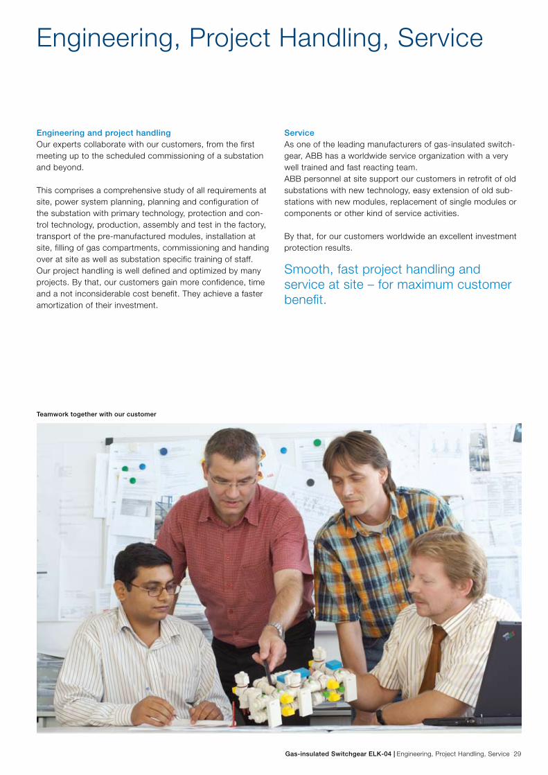
Teamwork together with our customer
Gas-insulated Switchgear ELK-04 | Engineering, Project Handling, Service 29

Summary, Technical Data
The gas-insulated switchgear of type ELK-04 represents the ideal solution for a reliable and environmentally friendly energy supply up to a rated voltage of 170 kV, a rated normal current up to 4000 A and a rated short circuit current up to 63 kA. The space saving, modular design and the high reliability guarantee an energy efficient usage not only in areas of high population density and at all other places, where a high ener-gy demand is requested. Moreover, already by now ELK-04 is an inherent part of regenerative energy sources like offshore wind farms or hydropower stations.
Since the market launch in the year 1992 the gas-insulated switchgear of type ELK-04 provides worldwide a valuable contribution to a reliable energy supply. ELK-04 meets a wide variety of technical requirements with a limited number of volume optimized modules. This applies for all primary technology components (parts under high voltage) as well
as for all secondary technology components. Transport, installation and commissioning can be arranged easily and fast due to the pre-manufactured and pre-tested components and modules.
High availability with reduced operating and maintenance costs guarantees excellent substation productivity. ELK-04, a future-proof decision.
ELK-04 in 1½-circuit breaker arrangement, outdoor installation in front of a conventional air-insulated switchgear
30 Summery, Technical Data | Gas-insulated Switchgear ELK-04

The above data should not be understood as limiting values. Further data upon request.
Rated Values according to IEC
Operating voltage kV 72,5 123/126 145 170
Operating frequency Hz 50/60 50/60 50/60 50/60
Lightning impulse withstand voltage against earth kV 325 550 650 750
Lightning impulse withstand voltage across isolating distance kV 375 630 750 860
Power frequency withstand voltage against earth kV 140 230 275 325
Power frequency withstand voltage across isolating distance kV 160 265 315 375
Normal current A 1250–4000
Peak withstand current kA 80–164 80–130
Short circuit breaking current kA 31.5–63 31.5–50
Minimum insulating gas pressure at 20 °C kPa 520/600
Minimum quenching gas pressure at 20 °C kPa 600/630
Permissible ambient temperature °C -30/+40
Encapsulation three-phase
Location of installation indoor/outdoor
Dimensions m 1.0 x 3.6 x 2.7 – 1.2 x 5.3 x 3.2 (for double busbar bay
with integrated local control cabinet and voltage transformer)
Weight kg 2400 – 3800 (for double busbar bay)
Circuit breaker operating mechanism hydromechanical, with energy storage in spring
Gas-insulated Switchgear ELK-04 | Summery, Technical Data 31

Contact us
1HD
X 5
8010
1 E
N
Prin
ted
in G
erm
any
(0
7.09
-100
0-G
D)
Kra
ft &
Par
tner
Wer
bea
gent
ur ·
Lei
menABB AG
High Voltage ProductsBrown-Boveri-Strasse 3063457 Hanau-Großauheim, GermanyTelefon: +49 (0) 621 381 3000Telefax: +49 (0) 621 381 2645E-Mail: [email protected] www.abb.com/highvoltage
Note:
We reserve the right to make technical changes or modify the contents of this document without prior notice. With regard to purchase orders, the agreed particulars shall prevail. ABB AG does not accept any responsibility whatsoever for potential errors or possible lack of information in this document.
We reserve all rights in this document and in the subject matter and illustrations contained therein. Any reproduction, disclosure to third parties or utilization of its contents – in whole or in parts – is forbidden without prior written consent of ABB AG.
Copyright© 2009 ABB
All rights reserved