proces ss con ntrol – – genera al requi irements s for ma
TRANSCRIPT
FLEXIAL QUALITY PROCEDURE QP159 Change History: See DCN for Details Rev Change
Date DCN Number
Initial Release A 08/12/04 DCN03633
B 9/30/13 DCN10841
C 1/20/2015 DCN12541
D 4/7/2015 DCN12791
Current Revision E 6/16/2016 DCN14177
Procedure Owner: Production Director
PROCESS CONTROL – General Requirements for Machined Parts
1. PURPOSE
1.1. This specification covers general product fabrication requirements. It also provides interpretation of certain
requirements specified on product drawings, models and electronic files. Specific requirements on product
drawings, models and electronic files, always take precedence over these general requirements and
interpretations. This specification is applicable to product that is defined using customary (inch) dimensions or
SI (metric). Unless otherwise stated, all linear dimensions not in [ ] are in inches and all linear dimensions in [ ]
are in millimeters in this specification.
2. SCOPE
2.1. This procedure applies to manufactured and procured machined components and tooling for internal use or by contract at Flexial Corporation.
3. GENERAL
3.1. All inspection authorities shall be responsible for the inspection and approval of configurations per this specification, engineering drawing and / or purchase order.
3.2. All components shall be machined using standard, industry accepted methods and tools. 3.3. A reference to a specification paragraph number includes all subordinate paragraphs. 3.4. Definitions
3.4.1. Design Agency: The design Agency is responsible for the design, development and evaluation or products. For this specification the design agency is Flexial Corporation. If the design agency is other than Flexial Corporation, other specifications may apply.
3.4.2. Production Agency: The production agency is the contractor responsible for the manufacture or procurement of products. If the production agency is other than Flexial Corporation they must be an approved supplier per Flexial QP320.
3.4.3. Supplier: The Supplier is an organization selling materials, parts, components, apparatus, or services to a
Design or Production Agency.
3.4.4. Buyer: For the purpose of this specification, a Buyer is a representative of either the Design or the
Production Agency.
3.4.5. As Read and/or As Measured Values: Both terms refer to readings obtained using measuring equipment
whose collective uncertainty tolerance is negligible when compared to the tolerances of the
characteristics being measured. When test accuracy ratios of 4:1 or greater are maintained or when the
product definition specifies the measuring equipment to be used, the resulting values can be directly
compared to the specified limits.
4. REFERENCES
4.1. The following form a part of this specification QP158 – Process Control – Thread Inspection QP230 - Handling, Storage, Packaging, Preservation, & Delivery QP320 – Approved Supplier List
5. DRAWING INTERPRETATION AND REQUIREMENTS
5.1. Drawing Interpretation

5.2. Drawing Symbols and Abbreviations.
5.2.1. Definition and interpretation of drawing symbols and abbreviations shall be in accordance with the
applicable documents listed in Paragraph 5.1.
5.3. Dimensions, Tolerances and Measurements
5.3.1. Dimensions
5.3.1.1. All drawing dimensions are in inch measurements unless otherwise noted.
5.3.1.2. Basic Dimensions
5.3.1.2.1. Untoleranced dimensions and dimension in boxes, except those identified as reference,
maximum, minimum, or stock dimensions, shall be interpreted as being basic dimensions.
5.3.1.3. Surface Coatings
5.3.1.3.1. Dimensional limits apply after/over metallic platings, dry film lubricants, electrochemical
and chemical film coatings. Dimensional limits apply before the application of primers, paints
or other such organic and synthetic coatings. When verification of dimensions is necessary,
the organic finish shall be removed and then replaced after verification. Also see Paragraph
4.3 a. on surface texture and Paragraph 5.10.3 on correcting defects in coatings.
5.3.2. Tolerance 5.3.2.1. Design shall provide the correct tolerance for each feature dimensioned, which means that the
desired value of the characteristic shall be within the tolerance stated and within the number of decimal places stated in the tolerance. An acceptable degree of conformance of product will be at the stated number of decimal places rounding will be used.
5.3.2.2. For statistical process control measurements, the resolution of the measurement shall be as
necessary to provide adequate sensitivity to indicate a process shift. This will be determined by a Minitab Measurement System Analysis (MSA).
5.3.2.3. Conversion
5.3.2.3.1. Specified Metric Dimensioned Products (SI -from Le Système International d’Unités) tolerances may be converted to U.S. customary units or vice versa by use of industry accepted conversion factors. The rounding method and number of decimal places retained shall not allow converted values to violate the original maximum and/or minimum limits. Regardless of the units of measuring instruments used, product acceptance procedures will be such that acceptance to the specified tolerance is assured.
5.3.2.4. Decimal Places
5.3.2.4.1. The characteristic being measured shall be within the tolerance stated by the engineering
requirement and will be reported with the same number of decimal places as stated in the
design requirements. When a dimension and its tolerance are not specified to the same
number of decimal places (Si drawings only), the largest number of decimal places shown
shall be inherent in the other elements of the requirement for determining the limits.
Example: 26 ± 0.2 Means: 26.0 ± 0.2
Example: 31.75 ± 0.1 Means: 31.75 ± 0.10
Example: 32 0 Means: 32.00 - 0.00
5.3.3. Interpretation of Dimensional Limits
5.3.3.1. Unless otherwise specified by contractual requirements, the interpretation of tolerances will be
matched to that stated on the design requirement. Where two decimal positions are given by
design, the measurement results will be documented/reported with two decimal positions. Any
measurement made beyond that on the design shall be rounded to the match the number of
decimal points on the design. Rounding will follow the following convention; on the top end of
tolerance 1-4 rounds down to 0, and 5-9 rounds up to 0. Examples shown below are in inches.
Example 1 - Dimension On Drawing 1.250 ±.005

Inspection Criteria: 1.255 to 1.245
Upper Limit Accept 1.2554 rounds to 1.255
Reject* I .2555 rounds to 1.256
Lower Limit Accept 1 .2446 rounds to 1.245
Reject* 1 .2444 rounds to 1.244
Example 2 - Dimension on Drawing 9.95 (per tolerance block XX is ± .01)
Inspection Criteria: 9.94 to 9.96
Upper Limit Accept 9.964 rounds to 9.96
Reject 9.965 rounds to 9.97
Lower Limit Accept 9.936 rounds to 9.94
Reject 9.934 rounds to 9.93
5.3.4. Measurement Procedures
5.3.4.1. Conformance to specified limiting values (+/- tolerances, maximums and minimums, for example)
shall be determined by comparison of measured (as-read) values with the specified limits using the
provisions of paragraph 5.3.2. Unless the product definition documents include requirements for the
use of specific measuring equipment, the collective uncertainty of the measuring equipment shall
not exceed 25% of the acceptable tolerance (minimum 4:1 test accuracy ratio) for each
characteristic being inspected. Specified “measuring equipment” as called out in the product
definition documents shall be interpreted to include, but not be limited to, design agency or
production agency built or purchased acceptance equipment and/or equipment, either unique or
generic, referred to in process standards, military, federal or public domain specifications that
specify uncertainty tolerances for that equipment.
5.3.5. Physical Measurement Temperature
5.3.5.1. Physical measurements of a product are considered to apply, when a CMM used for inspection,
only at a temperature of 680F [200C]. If referee measurements are required, the measurement shall
be made at 680F [200C] or adjusted to 680F [200C] to account for differences in thermal expansion
or contraction in the material of the gage and/or parts. The tolerance on the 680F [200C]
temperature is controlled by the degree of accuracy required for the measurement being made.
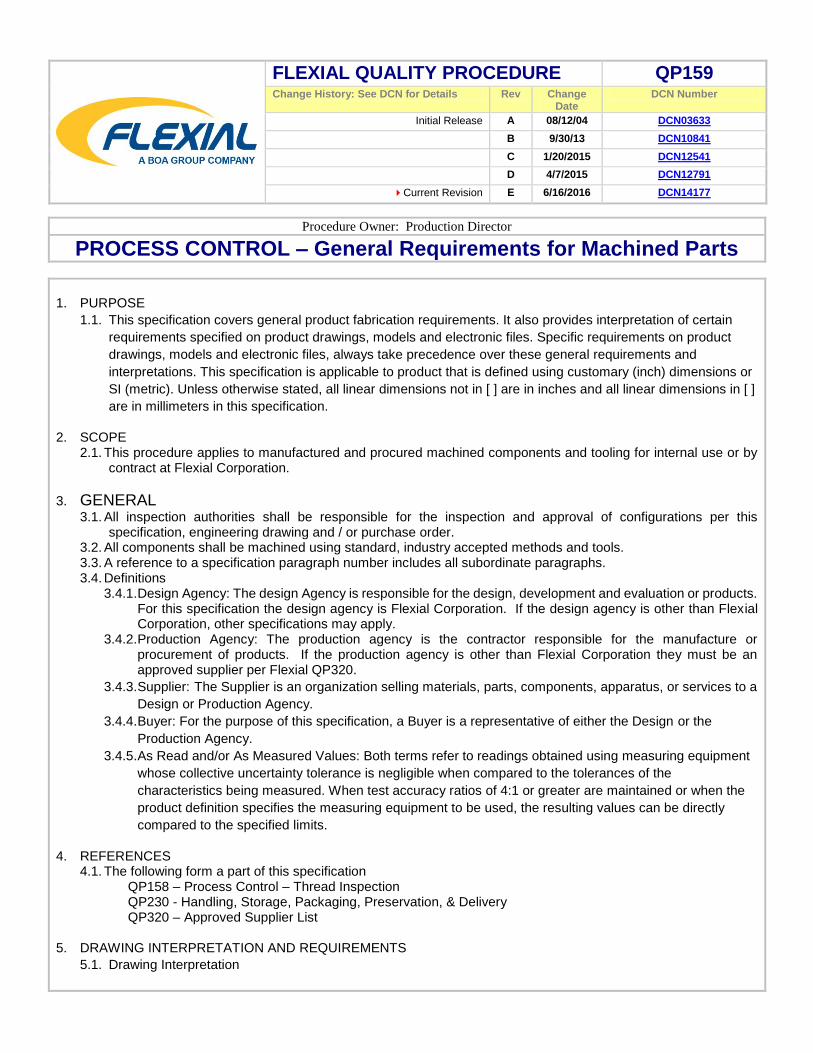
5.3.6. Counter Bores
5.3.6.1. In curved surfaces or on flat surfaces where the hole axis is not perpendicular to the surface, the
depth of a counterbore is the minimum distance from the bottom of the rim as shown in Figure 1.
The interior corner at the bottom of a counterbore produced by a standard tool is acceptable.
5.3.7. Counter Sinks
5.3.7.1. In curved surfaces or on flat surfaces where the hole axis is not perpendicular to the surface, the
diameter of a countersink is the diameter of the lowest point on the rim in a plane perpendicular to
the hole axis. See Figure 1. Holes for flat head screws shall be countersunk to allow the head of the
screw to be flush to 0.25 [.0 10] below the surface.
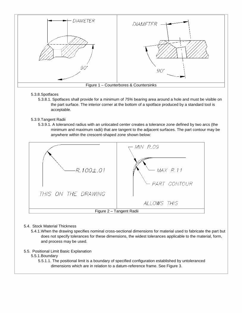
Figure 1 – Counterbores & Countersinks
5.3.8. Spotfaces
5.3.8.1. Spotfaces shall provide for a minimum of 75% bearing area around a hole and must be visible on
the part surface. The interior corner at the bottom of a spotface produced by a standard tool is
acceptable.
5.3.9. Tangent Radii
5.3.9.1. A toleranced radius with an unlocated center creates a tolerance zone defined by two arcs (the
minimum and maximum radii) that are tangent to the adjacent surfaces. The part contour may be
anywhere within the crescent-shaped zone shown below:
Figure 2 – Tangent Radii
5.4. Stock Material Thickness
5.4.1. When the drawing specifies nominal cross-sectional dimensions for material used to fabricate the part but
does not specify tolerances for these dimensions, the widest tolerances applicable to the material, form,
and process may be used.
5.5. Positional Limit Basic Explanation 5.5.1. Boundary
5.5.1.1. The positional limit is a boundary of specified configuration established by untoleranced
dimensions which are in relation to a datum-reference frame. See Figure 3.

Figure 3 - Boundary
5.5.2. Control
5.5.2.1. The positional limit is independent of the feature size. It controls feature location and may control
orientation. The feature must be located so that no portion of its surfaces shall extend into the
positional limit (boundary) specified. See Figure 4.
Figure 4 - Control
5.5.3. Interpretation
5.5.3.1. Positional limits may be used to control features of size as illustrated in Figure 5.

Figure 5 – Features of Size
6. SURFACE TEXTURE REQUIREMENTS
6.1. Surface texture requirements are expressed by symbols on the drawings. These symbols shall be interpreted
and the texture measurements performed. The following interpretation shall apply.
6.2. The surface roughness number is an arithmetic average (AA). For conversion to a root-mean-square (RMS)
value, RMS = l.1AA. Roughness limits, specified as a roughness height rating (RI-IR) or centerline average
(CLA), have the same meaning as (AA). Metric surface roughness is specified in micrometers. Customary
surface finish is in microinches, micrometers will be noted in []. The method of measure must be by industry
standard process or equipment.
6.3. The following table gives the metric (micrometer) equivalents for the customary inch (microinch) surface
roughness number. TABLE I - RELATED SURFACE TEXTURES
MICROMETER MICROINCH
0.025 1
0.05 2
0.1 4
0.2 8
0.4 16
0.8 32
1.6 63

3.2 125
6.3 250
12.5 500
25 1000
6.4. Applicability
6.4.1. Surface texture requirements apply over metallic platings, electrochemical and chemical film coatings
Surface texture requirements apply before the application of organic finishes.
6.4.2. Flaws in surfaces having specified surface texture limits shall be excluded from surface texture
measurements. Surface texture measurements shall be taken in the area and direction that will result in
the maximum reading.
6.4.3. Surface texture limits given in general note form do not apply to the cut edges of sheet metal, to the
surfaces of screw threads, to the walls of punched or drilled holes, or to the mold or flash lines of molded
plastic parts.
6.4.4. Unless otherwise specified, maximum surface roughness for all machined surfaces shall be 63 [1.6].
6.5. Stock Material Finish
6.5.1. When a “stock” dimension is called out, the surface finish must be the equivalent of normal finish for
commercially available stock.
7. DIMENSIONAL REQUIREMENTS AND ALLOWANCES
7.1. Formed Parts
7.1.1. Final material thickness may be “as formed” for areas of parts affected by forming processes such as
bending, drawing, or stretching.
7.2. Fillets
7.2.1. When two machined surfaces on a part intersect to form an angle exterior to the part of less than 180
degrees, there shall be a blending fillet of 0.4 [.015] maximum at the intersection of the two surfaces as
illustrated in Figure 6. No cut shall be made beyond the intersection of the two surfaces, unless relieved
as indicated in 7.4.
Figure 6 - Fillets
7.3. Turning Centers are permissible. 7.4. Relief
7.4.1. Diameters that terminate at a shoulder may be relieved as illustrated in Figure 7. The diameter, or both the diameter and the shoulder, may be relieved within the limits illustrated and may have any curved shape (no sharp corners) within those limits.

Figure 7 – Shoulder Relief
7.5. Plain Holes
7.5.1. Blind Holes
7.5.1.1. The drill point shall not penetrate or deform the material surface opposite the mouth of the hole.
7.5.2. Gaging Hole Diameters
7.5.2.1. The diameter of a hole is within required limits when accepted by “GO” and “NOT GO” plug gages
of appropriate size without reasonable evidence during plug gaging that the hole is out of round in
excess of the diameter limits. Performance of a variable measurement (micrometer, etc.) normally
will be required only for the specific holes that are suspect as a result of the “GO” and “NOT GO”
gaging. Bell-mouthed holes are acceptable if the “NOT GO” gage does not enter more than 20%
the nominal length of the hole as illustrated in Figure 8.
7.5.3. Hole Quality
7.5.3.1. The walls of holes shall be clean cut and shall present a good machined surface. Hole edges shall
be free from burrs and shall not be ragged, chipped, or torn. These requirements are subject to
visual inspection only and are to be evaluated in terms consistent with the characteristics of the
material and with the method used to produce the hole.
7.6. Removing Burrs and Sharp Edges
7.6.1.1. All burrs and sharp edges shall be removed to the extent that material fragments are not visible
and sharpness cannot be felt by using either a 0.015 [0.38] maximum x 0.015 [0.38] maximum
chamfer or a 0.015 [0.38] maximum radius. Only those edges that appear to exceed these limits
upon visual inspection need be measured for conformance to these dimensions.

7.7. Free State Variation
7.7.1.1. If material flexibility or normal internal stresses can be expected to cause parts to be out of
tolerance, appropriate inspection procedures shall be obtained from the Buyer prior to the
manufacture of parts. Sec 3.4.4.
7.8. Coaxiality and Symmetry
7.8.1. Machined Diameters
7.8.1.1. Where no coaxiality requirement (positional, runout, or concentricity tolerance) is specified the
datum diameter and any other diameter having a common axis (including holes, countersinks and
counterbores) shall be coaxial within a Full Indicator Movement (FIM) of one-half the arithmetic sum
of their size tolerances. THE DIAMETER HAVING THE SMALLEST TOLERANCE SHALL BE THE
DATUM FEATURE FOR ALL COAXIAL DIAMETERS. See Figure 9. If size tolerance values are
equal, the diameter having the longest axis shall be used as the datum feature.
Figure 9 – Machined Diameters
7.8.2. Machined Widths
7.8.2.1. Where no symmetry requirement (positional tolerance) and no locational tolerance (positional,
profile, or non-geometric) are specified, the datum width and any other width having a common
center plane shall be located symmetrically about this center plane within one-half the arithmetic
sum of their size tolerances. THE WIDTH HAVING THE SMALLEST TOLERANCE SHALL BE THE
DATUM FEATURE FOR ALL SYMMETRICAL WIDTHS. See Figure 10. If size tolerance values are
equal, the feature having the longest center plane shall be used as the datum feature.

Figure 10 – Machined Widths
7.8.3. Combination of Machined Diameters and Widths
7.8.3.1. When a diameter and a width share a common axis, and where no coaxiality or symmetry
requirements are specified, both features shall be located symmetrically about this axis within one-
half the arithmetic sum of their size tolerances. THE FEATURE (DIAMETER OR WIDTH) HAVING
THE SMALLEST TOLERANCE SHALL BE THE DATUM FEATURE. See Figure 11. If size
tolerance values are equal, the feature having the longest axis shall be used as the datum feature.
Paragraphs 7.8.1 and 7.8.2 shall apply for any additional diameters or widths. See Figure 12.
Figure 11 - Machined Diameters and Widths
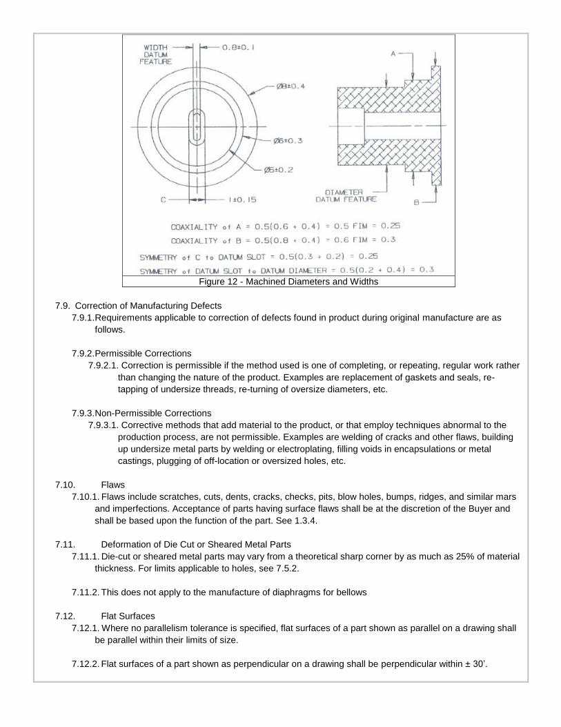
Figure 12 - Machined Diameters and Widths
7.9. Correction of Manufacturing Defects
7.9.1. Requirements applicable to correction of defects found in product during original manufacture are as
follows.
7.9.2. Permissible Corrections
7.9.2.1. Correction is permissible if the method used is one of completing, or repeating, regular work rather
than changing the nature of the product. Examples are replacement of gaskets and seals, re-
tapping of undersize threads, re-turning of oversize diameters, etc.
7.9.3. Non-Permissible Corrections
7.9.3.1. Corrective methods that add material to the product, or that employ techniques abnormal to the
production process, are not permissible. Examples are welding of cracks and other flaws, building
up undersize metal parts by welding or electroplating, filling voids in encapsulations or metal
castings, plugging of off-location or oversized holes, etc.
7.10. Flaws
7.10.1. Flaws include scratches, cuts, dents, cracks, checks, pits, blow holes, bumps, ridges, and similar mars
and imperfections. Acceptance of parts having surface flaws shall be at the discretion of the Buyer and
shall be based upon the function of the part. See 1.3.4.
7.11. Deformation of Die Cut or Sheared Metal Parts
7.11.1. Die-cut or sheared metal parts may vary from a theoretical sharp corner by as much as 25% of material
thickness. For limits applicable to holes, see 7.5.2.
7.11.2. This does not apply to the manufacture of diaphragms for bellows
7.12. Flat Surfaces
7.12.1. Where no parallelism tolerance is specified, flat surfaces of a part shown as parallel on a drawing shall
be parallel within their limits of size.
7.12.2. Flat surfaces of a part shown as perpendicular on a drawing shall be perpendicular within ± 30’.

7.12.3. The perpendicularity requirement for a flat surface and an axis, or an axis and another axis, shown
perpendicular on a drawing, is that they shall be perpendicular within ± 30’.
8. Threaded Part Requirements
8.1. General
8.1.1. See QP-158 for Process Control for Thread Inspection
8.1.2. Form and Class of Fit
8.1.2.1. All threads shall conform to the drawing requirements whichever applies to the thread size, form,
and class of fit specified. Thread callouts on drawing are specified in inches unless otherwise
noted.
8.1.3. Appearance
8.1.3.1. All threads shall be free from burrs, nicks, and rough or chattered surfaces, that are visible without
magnification.
8.1.4. Lubrication
8.1.4.1. Oil-free gages shall be used on beryllium parts. Gages used on items having extremely stringent
cleanliness requirements shall also be oil-free if the item cannot be cleaned after thread gaging is
performed. For other applications, the threads of “GO” and “NOT GO” plug and ring gages should
be lubricated with a very thin film of low viscosity non-silicone oil. Gages that have been cleaned
with degreasing solvents such as alcohol or trichloroethylene shall be lubricated before reuse.
8.2. External Threads
8.2.1. Thread Length
8.2.1.1. Dimensions of axial thread length shown on drawings indicate minimum required length of
complete threads. When the dimensioned thread length terminates at a shoulder and an undercut is
not specified, the two threads next to the shoulder may be incomplete. As an alternate, an undercut
to the minor diameter, within its tolerance, for a maximum of two threads is permissible.
8.2.2. Chamfer
8.2.2.1. The leading end of externally threaded parts shall be chamfered. The resulting incomplete threads
are included in the measurement of thread length but must not exceed two pitches in length.
8.2.3. Coated Class 2A Threads
8.2.3.1. Class 2A threads to which metallic plating, chemical-film coatings, resin bonded dry film lubricants,
or any combination thereof have been applied may be gaged with basic “GO” gages in determining
conformance to maximum size limits.
8.3. Internal Threads
8.3.1. Tap Drills
8.3.1.1. The hole diameter prior to tapping shall be of a size that will assure a tapped thread height that
falls within the guidelines of ANSI/ASME B 1.1. The formulas contained therein are suitable for
general applications having lengths of engagement up to 1.5 diameters. The thread height
requirement may be reduced to 55% for tapped holes having a thread depth exceeding 1.5 times
the nominal thread diameter. Acceptance criteria for final threaded hole dimensions shall be per
drawing requirements.
8.3.2. Blind Hole Depth
8.3.2.1. The tap drill point shall not break through or deform the surface opposite the mouth of the hole.
8.3.3. Thread Depth
8.3.3.1. Dimensions of axial thread depth shown on drawings indicate minimum required depth of complete
threads.
8.3.4. Perpendicularity

8.3.4.1. Where no projected tolerance zones are specified, the perpendicularity or normality of threaded
holes in flat or curved surfaces shall be within ± 1~ 0’. In meeting this requirement, measurement
may be made using the pitch diameter, the major diameter, or the minor diameter of the thread.
8.3.5. Chamfer
8.3.5.1. The leading ends of internal threads shall be chamfered as shown in Figure 13. If accessible, both
ends of through-tapped holes shall be chamfered. Chamfering shall not result in elimination of more
than one pitch of thread depth. For the purpose of determining the number of complete threads
from the surface adjacent to the hole, the chamfered thread may be counted.
Figure 13 – Internal Thread Chamfer
8.3.6. Hole Tapping Option
8.3.6.1. Cold forming thread taps such as Besly “X-Press” taps may be used in lieu of metal cutting taps. A
slight groove may appear along the thread crest (see Figure 14) as a result of the metal flowing
action of these taps. The groove is acceptable if the overall thread crest height conforms to limits.
Figure 14 – Cold Forming Thread Taps
9. Metal Heat Treatment Requirements
9.1. When necessary to facilitate fabrication, parts made from heat-treatable alloys, for which material is specified
in terms of the final temper or condition required, may be fabricated from raw stock of a temper or condition

different from the final temper and then heat-treated to the specified temper or condition.
9.2. After the completion of in-process heat-treatment, sample parts from each heat-treat lot shall be tested to
determine that the material properties influenced by heat-treatment conform to the applicable material
specification requirements. If tests of actual parts are impractical, suitable samples of the same alloy and
starting condition as the parts shall be heat-treated with the lot and tested for conformance to the applicable
requirements.
9.3. Parts specified to be made from a work-hardened temper of a non-heat-treatable alloy must be fabricated from
material of the required temper or condition.
9.4. Thermal treatments such as hot forming, stress-relieving, drying, bonding, and baking, other than those
specifically permitted by the product drawings, shall not be used.
10. Requirements for Cleaning, Protection and Identification of Raw Materials and Assemblies
10.1. Protection
10.1.1. All parts and assemblies shall be adequately protected from accumulation of foreign matter, corrosion,
physical damage or deterioration. This requirement shall apply to all manufacturing operations from
receipt of raw material to completion of a finished product, to product held in any storage area, and to
product prepared for shipment.
10.1.2. Protective measures used during processing, fabricating, and packaging must not only guard against
obvious damage and deterioration but also against the creation of latent conditions that may later cause
unsatisfactory performance, accelerating deterioration, or malfunction.
10.1.3. All items such as raw material, parts, subassemblies, assemblies, etc., not in immediate use, shall be
adequately packaged, identified, and stored per Flexial QP-230
10.2. Cleanup of Parts and Assemblies
10.2.1. All finished parts and subassemblies shall be adequately cleaned before final assembly. Final assembly
and necessary subassembly shall be performed in an environment appropriate to the type of product. All
parts and assemblies shall be thoroughly cleaned to remove foreign and manufacturing waste material
such as:
Superfluous hardware, wire, and insulation clippings.
Chips, filings, abrasives, machining lubricants.
Soldering, brazing, and welding fluxes, solder droppings, weld splatter, slag, and welding rod ends.
Drippings of lubricants, adhesives, and sealing compounds.
Paint droppings, splatter, and overspray.
Residues from liquid baths used in plating and chemical treatments.
Temporary tags and packaging.
10.2.2. See the process instruction sheets (routings) for the proper cleaning process