proceedings of the 1961 conference on linear...
TRANSCRIPT
XII. K. Brown (Stanford University)
Prc"'3rties of Iris-Lo!'l.t;ied Guides
Before discussing some of the elementary theory of iris loaded structures
a sample list of useful references is given:
Slater, J.C., Rev.Mod.Phys. 20, 473, 1948
Fry and Walkinshaw, Reports in Progress in Phys. XII, 102, 19L8-l949
Chodorow et al, R.S.I. 26, 134, 1955
Stanford Linear Accelerator, Hearings for a Congressional Co~~ission
of the U.S. Gover~~ent Printing Office 43633 0, 1959
Ginzton, Hansen and Kennedy, R.S.I. 19, 89, 1948
Chu and Hansen, Journ. Applied Phys. 20, 280, 1949
Journ. Applied Phys. 8, 996, 1947
Loew, G.A., M.L. Report No. 7L~o, Aug. 1960
Neal, R.B., M.L. Report No. 379, March 1957
Leiss, J., Internal memoranda on the Behaviour of Linear Electron Acceler
ators with be~~ loading. Internal report - National Bur. of Standard~
Sept. 1958
Stanford Status Report -~- - April I-June 30, 1959, M.L. Report 640
Neal, R.B., Report 185, Feb. 19)3
Chu, E.L., Report 140, Microwave Laboratory, May 1951.
Demos et al, Journ Appl. Phys. 23, 53 (1952)
Stanford Project M Staff Project M Source Book
A rather complete list of references is given by L.Smith in ItHandbnch der
Physik" band XLIV, 3L.l-389.
Proceedings of the 1961 Conference on Linear Accelerators, Upton, New York, USA
60

Consider the basic structure, illustrated below, of a typical iris loaded
waveguide as used for linear electron accelerators.
In general this is a circular symmetric waveguide energized in the TMOI mode.
In trave ling wave acce lcra tors usually the rr/2 mode (4 dis cs per \vavelength)
are used.
The following parameters (as indicat8d in the figure above) will have to be
I I I( f . rr.l!! chosen~ A,a Afb A,d A re ers to elther 2' 2
total length i . or other mode), /1 d ( ""t) and the
'/
The choice of a and b will be affected by the value of the group velocity,
Vg (power flow into the structure), i.e., Vg ~7 Fl(~) and by the value of the
desired phase velocity, v¢ (velocity of accelerated particle), i.e.,
(v¢)-l ';;-= F2 (b - a).
For optimum values of shunt im;::>ed-mce it is usuc,lly dC3:~rable that il d ;: t
shall be as small as is compatible with fabrication. On the other hand for small
values of t there is a greater danger of arcing at the disc apertures. An
example of the influence of disc th:tckness on shunt impede>.nce i.s given i.n the
table below for a few specific cases~~ (Values accurate to about ±5 percent)
i~ It would seem to be very useful to compare these experimental results with cal
culated values as can be obtained from the work done at Yale University and MURA.
Proceedings of the 1961 Conference on Linear Accelerators, Upton, New York, USA
61

n ...
n ==
n
t(inch) 2b(inch) 'r/Q Q r 2b!!1§ cm
;2 ( d=2.063 inches, 1T mode)
0.061 3.208 60 17000 5.05 105 o
0.1?0 3.203 61 16900 5.20 105 o
0.230 3.198 61 17200 5.25 105 o
3 (d=1.378 inches, 21T/3 mode)
o ,~C'l .~'-'- 3.216 48 13200 6,,35 105 0.0194
0.120 3.214 50 13000 6.50 105 0.0142
0.230 3.213 51 13200 6.74 105 0.0080
4 (d=]..034 inches, 1T/2 r:;.ode)
0.061 3.~17 :'4 9100 5.40 105 0.0191
O.::'?O 3.219 53 10100 5.41 lC5 0.0143
0.230 3.224 51 9950 L.97 105 0.0084
f = 28'~6 Mel" 20. == .. s" 0.8225 inches; ~¢ == 1.0 ::: normalized phase velocity.
Factcrs influencing the chcic~ o
of /:,.. "'.re the att·".inablA Q of the cavities, o
the degree of beam loading, frequency. the choice of group velocity and the
dimensionRl tolerances attainable.
Dimensional errors in the structure cause a relative rh3.se shift behreen
the accelerated p~rticles and the trav~li:'lg wave, cor_sequ..:mtly a broad3r energy
spect"':'um at the output and a l()ss in bea.'11 energy. The m08.tLematical details of
this will be discussed in the following, here only th0 cO:!.("· '- usinr,s will be
given; i.e., t}-"~Lt the required dim'.?ns~_,:)l131 tolerances on 2b 'fer a fractional
energy loss sma.ller than 0.005 is tric".lly of tho order of :!::0.0002 inches for
A ::: 10.5 ems. Tnese tolarances .::.re 2: t;tain.2ble '"lith careful machine Fhop practice. o
An alternative is, with slightly 12s8 rig::Jrous requircme:1+s in tcJ -::::-C'..DC-GS to
tune each cavity individually by deform..-i..ng the wall bet1vc3n the irises; however
it is not desirable to rely upon this completely - hence, t.oJ.er.:mce.s are usually
held as close as possiole and the deforma-::'ion is relied upon only as a final
Proceedings of the 1961 Conference on Linear Accelerators, Upton, New York, USA
62

tuning adjustment.
The fabrication of individual accelerator cavities has developed along
different lines. If many identical sections are necessary the process of
electroforming (used at Stanford University) is economical and with care
produces the desired tolerances. The problems involved are plating the copper
in such a way that an oxygen -free copper body is produced to facilitate later
soldering and to minimize outgassing of the surfaces. An alternative method,
usually ernployed for commercial linacs, is to solder individual cavities together.
In a proton linear accelerator one would normally encounter a sufficient
number of different sections (because of the range in ~ values) to make the
electroforming technique uneconomical compared with t he soldering technique.
The selection of the operating mode is guided by several factors of which
the value of the shunt impedance is the dominant one. Before treating this
in more detail, it is worth while mentioning the following observed phenomena
which have bearing on the selection of the operating mode.
In high energy linear accelerators with electron currents in excess of
200 mao it has been observed that the transmitted beam pulse length may be
shortened as a result of radial defocusing effects resulting from a backward
wave oscillation in a TMll type mode generated by the beam.
This is illustrated in the following diagram where both characteristics
for forward and backward wave are drawn •
21ff = W
. , /--- backward wave mode I ----- , t' _____ ~ ____ I ~.e., Vg nega ~ve
~.~ / "~'; ///
/ . /, / ----------------.---------
----._,-'-,
forward wave mode, v positive
g 1f mode
Proceedings of the 1961 Conference on Linear Accelerators, Upton, New York, USA
63
TT The operating point for the 2 mode can coincide with the operating point of
a different mode in the backward wave. These difficulties have been minimiz~d
2TT by using L band and the ~ mode. This combination has made it possible to go
to higher currents and longer pulse lengths before pulse shortening is observed.
It is, of course, possible to suppress the TIMll mode in the waveguide~ but
only at the expense of decreasing the Qo value for the fundamental mode. Also
the fabrication tolerance p~oblems arising from mode suppressors are not trivial.
Elementarx Theory of Traveling Wave Lina£§
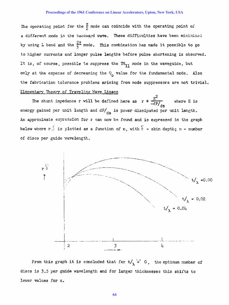
The shunt impedance r will be defined here as where E is
energy gained per unit length and dP/dZ is power dissipated per unit length.
An approximate expression for r can now be found and is expressed in the graph
below where r j is plotted as a function of n, wi th ~ = skin depth; n = number
of discs per guide wavelength.
I
-~-. -I 2 I
------~.-----.. -------~.-...--- ------
~~,---'''-'--.
0.02
_______ l _____ . __
3 4 ---.---.
From this graph it is concluded that for t/A';~ 0, the optimum number of
discs is 3.5 per guide wavelength and for larger thicknesses this shifts to
lower values for n.
Proceedings of the 1961 Conference on Linear Accelerators, Upton, New York, USA
64
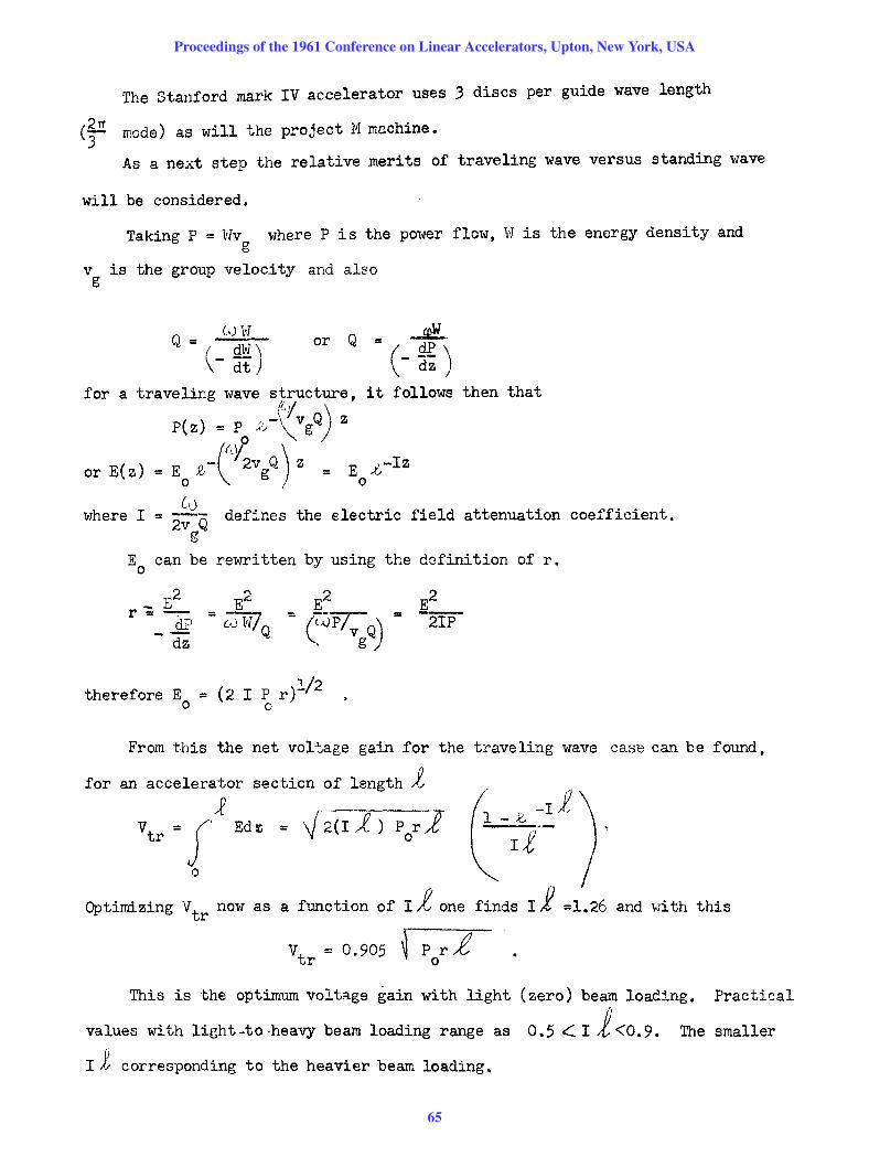
The Stanford mark IV accelerator uses 3 discs per guide wave length
(~ mode) as will the project M machine.
As a next step the relative merits of traveling wave versus standing wave
will be considered.
Taking P = Wv where P is the power flow, itJ is the energy density and g
v is the group velocity and also g
or Q - ~ - (- ~~)
it follows then that
where I attenuation coefficient.
E can be rewritten by using 0
the definition of r.
_ E2 E2 E2 E2 r = --:-- = 0J W!Q =
(WP!vgQ) ". 2IP elF --dz
therefore Eo = (2 I P r//2 o
From this the net voltage gain for the traveling wave caSB can be found,
for an accelerator section of length ~
Vtr = f,J Ed, = '1/ 2(I 1) por-;{
o
Optimizing V tr now as a function of I i one finds If =1.26 and vJi th this
Vt = 0.905 r P r L r 0
This is the optimum voltage gain with light (zero) beam loading. Practical
values with light -to -heavy beam loading range as 0.5 <:. I 1 <0.9. The smaller
Ii corresponding to the heavier beam loading.
Proceedings of the 1961 Conference on Linear Accelerators, Upton, New York, USA
65

Comparing this voltage gain with the voltage gain for the standing
wave case
A further point for comparison is the fact that in the standing wave case the
field builds up from zero to a steady state value Es as
-(l\+'2Q E = Es (1 - ~ ~ L)
Therefore, as expected, a built-up time is needed before acceleration; the
main point is, however, that for a standing wave accelerator the field never
reaches an equilibrium value. For the case of traveling waves a certain delay
is also needed before acceleration, given by the filling time ~ which is related
to the attenuation constant I as
L = 2119 -.J:t' 0.J
but equilibrium is obtained for t > ~.
Another drawback in the case of a standing wave accelerator is that the
impedance presented to the rf power source varies during the build-up time as
.1- fJJ -tv t/ 2Ql
From this: t = 0 gives Z = 0 , t = ~ gives Z = Z o
This characteristic can cause difficulties with the rf power sources.
In the above the energy gain (V) has been obtained by assuming zero beam
loading. Now this will be taken into account. In the case of synchronous
operation (i.e., the particles riding on the crest of the w2~le) the relevant
differential equations are
~ . In the literature the shunt impedance is sometimes tabulated . (tor the standjng
wave case) directly as (~) instead of r.
Proceedings of the 1961 Conference on Linear Accelerators, Upton, New York, USA
66

ar:d
£E + 2IP + iE = 0 dz
~~ + IE + Iri - 0
with the solutions
p(z) = P .t -2Jz o
E(z) '" E £ -Iz \ 0
These equations hold for synchronous particles. In case the particles
are not riding on the wave crest cosG terms have to be introduced, in this
case, E(z) must be separated into two quadrature components, nC':'lely,
and
-Iz = E cosO o ° (0 u-Iz) - l.r l.-.IV
1. For the ene~gy gain)only El(Z) is of concern andOfrom this
V· EJCOSQ~-;lI~} ir£ ~ l-£It:]. V = f EI dz gives
o
. ITC~) V 2 It is useful here to define an expression R ~ \i- /..-R - r (,j J!~( , th d fO . t" f Q P d ) :: Q V h us:.ng J. e e l.nl. ~ons or , an r. or
g
This substitut:"i yie:ds
1/2 QI_J.,-·~f) ~Tl l-l _ Ij .. !_7 + f.'·._ .... ,~ __ )2_ .(To:o·f~ " ,3+ .... J V = (p R) "cos~--;"'lr-- - .:!';;':: .' -' .. ~- ~~ o ..Lh 4
~ .. -Ren8I:}Jering that I::: 'Z"l Q 0:1,3 fJ.!>.-:'1S :01:' h:~c'c, Q Vc\·.L:.es, and ccnsequent1y g
small I i values
Proceedings of the 1961 Conference on Linear Accelerators, Upton, New York, USA
67

Ass~mrlng cosG = 1 , V can be optimized as a function of R resulting in
(With R = ~Q). J.
V :: P /i o
similarly E:: Eo (1 - z~ ) (Q -70(: or I~ 0)
and ,.i = 2P liE . o 0
This determines optimum section length depending on what field gradients are
tolerable and what rf power sources are available.
From the above, group velocity and filling time can be simply evaluated
and are given by
v = C g
Using the equations derived thus far and assuming a 1 megawatt power source (p ) o
and current loading of 1 mao (i)
for Q --1- 6J or IX} ~ 0
then V = 1 Bev
)~.; 333 ft.
tF ~ 424 llsec
~ '2 (1300)-1 g This value of ~ is too low because of the tolerances
g demanded in this case.
Therefore, these figures are obviously impractical.
Assume E = 105 volts/cm = 3 Mev/ft. which is practical, ave
and ~g = (100)-1 allowing reasonable tolerances,
then Po = 12.7 megawatts
tF 0.424 = i
tF = 1 ~sec
V '" 30 Nev
j :: 10 ft.
~sec and with the choice of i :: 0.424A
Proceedings of the 1961 Conference on Linear Accelerators, Upton, New York, USA
68

Other examples may be easily evaluated from the preceeding equations. However, it
is easy to conclude that if extremely high Qts can be obtained, the standing wave
machine becomes of considerable interest again as compared to the traveling wave
case. This is particularly true of machines having peak beam currents~, 1 ampere.
In the event that high Qts become attainable, a aN standing wave machine would be
of considerable interest since high average power microwave sources are already
available. Clearly there are many practical problems that must be solved in such
an event, but the possibility should not be overlooked.
Going back to the case where Q is finite, as has been stated previously, the
optimization for Ildepends upon the degree of beam loading. Included below are
two tables taken from the Project M source book which illustrates the choice of
design parameters for a 10 percen~beam loaded electron linac. The first table
shows the effect of frequency upon the choice of machine parameters. The second
table gives typical values of design parameters for a 10 Bev linac (~¢ = 1) for
3 different frequencies. In the case of a proton linac the current would be less
than quoted here but the remaining figures should be substantially the same.
* Ten percent beam loading here means the full load energy is 0.9 of the no load energy.
Proceedings of the 1961 Conference on Linear Accelerators, Upton, New York, USA
69

Table 1
Frequency dependence of principal machine parameters.
Parameter
shunt impedance per unit unit length (r)
rf loss factor (Q)
filling time (tfl
total rf peak power
rf feed interval (t)
number of rf feeds
rf peak power per feed
rf energy stored in accelerator
beam loading (-dV/di)
maximum peak beam current
diameter of beam aperature
max. rf power available from single source
max. permissible electric field strength
relative frequency and dimensional tolerances
absolute frequency and dimensional tolerances
power dissipation capability of accelerator structure
Frequency Frequency Preference Dependence High Low
f- l / 2
-3/2 f
f- l / 2
f- 3 / 2
f3/2
f- 2
f- 2
fl/2
f- l / 2
f- l
x
x X
X
X
X
X
x
x X
X
X
X
X
X
X
Notes
(1)
(1)
(1), (2)
0),(2),(3)
(1 ), (2 )
(1),(2),(4)
(1),(2),(3)
0),(2),(3)
0),(2),(4)
0), (2), (3), (6)
(1)
(5 )
(7 )
(1),(2)
0), (2)
(1),(2),(4)
Notes: 1. For direct scaling of modular dimensions of accelerator structure.
2. For same rf attenuation in accelerator section between feeds.
3. For fixed electron energy and total length.
4. For fixed total length.
5. When limited by cathode emission.
6. When limited by beam loading.
7. Approximate: empirical.
Proceedings of the 1961 Conference on Linear Accelerators, Upton, New York, USA
70

50 percent beam loading
I
Table 2
Design parameters of a 10 Bev electron accelerator at 3 frequencies. l
'shunt impedance per un it length (r)
rf lOBS factor (Q)
filling time (t F)
total rf peak power
rf feed interval
rf energy stored in accelf.!rat::n
(L-Band) lCXX) Me/sec
0.27 x 10⁶
2.25 <\
xlO
4052
2490
52
185
13.5
6580
Frecp1encr (S-Band) I (X-Band)
'30CXj Mc/secl 9000 Me/sec
0.47 ).. 106 ! 0.81 x 10⁶ ohms lem
1.3 x 10⁴ O. 15 x 10
4
0_87 0.17 Llsec
1440 830 Mw
1') 1. 92 ft.
960 ti Cl(\.~·
1.J 0.17 ~'h.\-·
731 81 .]C;U t,:?:5
I rf t?nergy requi r~d for 1.63 u .. sec electron beam pulse length
total average rf power at 360 pUlses/sec
; 5, 300
5050
beam loading (-dV/di) for max
max peak beam cu r ren t beam powelr
19.6
294
diameter of beam apertur,')
max rf peak power available from single source
max permissible electric field strength2
max expanded beam energy3
relative frequency and dimensional tolerances4
absolute frequency and dimensional tolerances4
average power diss ipa ted per unit area of accelerator surfaceS
average temperature difference across accelerator wal1 6
2.670
216
133
29.3
-5 0.98 x 10
87 kc/sec, 0.09 mils
0.17
0.55
360.:1
1. 30
34.2 -
170
0.890
24
230
50.7
-5 1.70 x 10
50 kc/sec; 0.05 mils
0.12
0.13
15CO JC'lJ.et'l
0.54 Mw
59 Bev I amp
98 rna
0.297 inch
2.7 Mw
398 kv/cm
87.6 Bev
2.94 x 10- 5
29 kc/sec; 0.03 mils
0.15 watts /ern 2
0.05 degrees C
l.Assumptions: 2Tt/3 mode: Ii.0.6 nepers (rf attenuation); Vo = lL6Bev (noload beam enerqy); L = 9600 feet;direct scaling of modular dimens ions.
2.Ba.ed on max gradient obtained to date at S-band, values for other fre-quencies based on scaling as fl/2.
3.As limited by max~ permissible field strength. 4.For one per cent loss in beam energy. 5.Based on 360 pulses per second and 1.63 ~sec electron beam pulse lenqth. 6.Based on copper wall 1/3, 1, and 3 em thick at XIS~ and L-bands,respec-
tively.
Proceedings of the 1961 Conference on Linear Accelerators, Upton, New York, USA
71

If higner ave:rage-energy gradients are desired, it is desirable to use
accelerator sections which are geometrically not identical. In this case, a
design of non-uniform geometry but constant axial fields (Le., constant gI'ad~ent)
over the full. length of the structure becomes interesting. Normally with
repetitive geometries there is an exponential decay of axial field with distance
from the rf power source.
The ratio of peak-to-average field in the repetitive structure may be
as high as 1.76 although in practice the ratio is more likely to be of the order
of 1.4 because of the choice of IX. Therefore higher energies by this factor
could be obtained with the constant gradient structure before similar voltage
breakdown problems are encountered.
At present the uniform structure accelerator is chosen at Stanford for the
Mark IV accelerator, however, a point-by-point comparison suggests that a constant
gradient structure merits further Gonsideration.
Some discussion regarding shunt impedance versus the normalized phase velocity ~¢ of disc loaded structures.
The table below shows some experimental values of shunt impedance obtained
for a disk loaded structure at S-band frequencies and for the 2n/3 mode
(p.er guide wavelength).
~¢ Qo r/Q r 0
1.0 13000 47 ohms/em 6.1 105 ohms/em
0.45 12500 45 5.65 105
0.40 12050 42.5 5.12 105
0.85 11500 40.0 4.60 105
0.80 11000 36.9 4.06 105
0.75 10400 33.5 3.48 105
0.70 9800 29.7 2.91 105
0.65 9130 25.7 2.35 105
0.60 8470 21.0 1.78 105
0.55 7700 16.7 1.29 105
~¢ = ~ = normalized 0.50 6930 12.2 8.47 104 phase velocity
Proceedings of the 1961 Conference on Linear Accelerators, Upton, New York, USA
72

This table was evaluated by measuring all r/Q values to an accuracy of ±5 percent
for the respective ~0
The Q values were calculated and then normalized to the measured value
of Q at f3¢ = 1. This means that for example at f3 :: 1/2 the r values have
an accuracy of approximate~.y 10 percent at best. (Q values ± 5 percent.,)
That the Q values decrease for lower phase velocities can be eA~lained
qualitatively by the fact that (b - a) becorr.es greater allQ consequently there
is a larger surface area and current concentration near the apo~ture edge,
resulting in a lOWer Q value.
Tolera~
Variations in frequency, temperature, axial field strength, input rf phase
and dimensional errors all have an influence on the performance of the Linac.
In general most of these errors may be expressed as an equivalent phase slip
between particle and traveling wave with a consequent beam energy spread
at the output and a beam energy loss.
by
where
The fractional beam energy loss due to a frequency change df/f is given
av _...2 V o
Substituting some typical values in this equation one finds that in
order to kee\~:Q \~-O.OO5 it is necessary to keep Of< 35 kc/s.
The total phase shift deviation Que to dimensional errors in individual
cavities should be assessed on the basis of an accumulation of random errors,
neglecting here systematic errors. Considering now the phase shift error
per cavity for a ~ mode 3
~ ¢ = 120 p.c.
Proceedings of the 1961 Conference on Linear Accelerators, Upton, New York, USA
73
One finds if ~ d maximum is taken as 0.6°, in connection with the o )£Ip. C.
maximum tolerable energy spread, that the required dimensional tolerances
are to. 0002 irches. In this CaJ8 the total accum'J la.ted pl:ase shift, due to
r2ndom error] is where N is the number of cavities.
Also t.:::mperature v.::lriati0ns in the accelerator structure have to be cJ.osely
controlled. A rise in te~p0rature causes an increase in the resistivity of
tbe ac,-;elera:sor wall uit.h a c0usequent decreDse of Q and r, but of g'~eater
i;""PO:-t,:"1.1CO ,Vc8 cav:~ ty di;n::;:r:.sions increese, with a ccnsequE.nt drop in ph2se
velocity (ass~~ng f = co~stant), resulting in a phase slip between particles
and the traveling wave.
The follmd.ng simple expression gives the influence of t~n'perature on
operating frequency:
U f = - g 8 T where g is the linear coefficient
of expansion of the material of the cavity wall. Referring back to the
expressio~ for fractional beam energy loss due to d~ one finds for
~v I ~0.005 that temperature variations should not exceed O.SoC. o
(using the g value for copper).
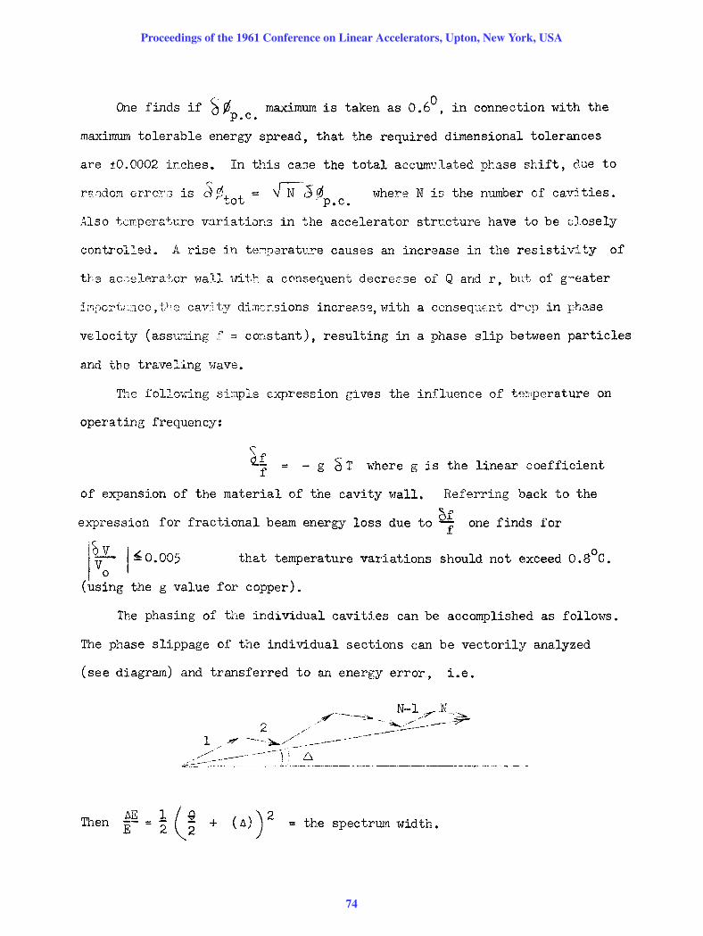
The phasing of the individual cavities can be accomplished as follows.
The phase slippage of the individual sections can be vectorily analyzed
(see diagram) and transferred to an energy error, Le.
Then -Et:.J]! -- 12 (~2 + (A) ) 2 th t . dth ~ = e spec rum w~ •
Proceedings of the 1961 Conference on Linear Accelerators, Upton, New York, USA
74

At the output of the accelerator (in the Stanford case) a beam analyzer
is used and the collector current can b~ expressed as
L I o
where I = I for A ~ 0 o and g = phase spTead of the bunched electrons. As
can be seen from the vector diagram above it is only necessary in general to
phase section N to make A ~ o. The whole accelerator may be optimized in
successive steps by changing the phase in each section to optimize the output
and each time making A = 0 by changing the phase in section N. The procedure
will converge to the correct solution and should result in a correctly phased
machine.
As a concluding remark it should be stated that the arguments brought
forward above might not necessarily apply directly to a proton linear accelerator.
The basic difference lies in the y = (1 - ~2)-1/2 of the particles in question.
Proceedings of the 1961 Conference on Linear Accelerators, Upton, New York, USA
75