problems. journal of guidance, control, and dynamics (3 ... · system with a prop er understanding...
TRANSCRIPT
Rezgui, D., Lowenberg, M. H., Jones, M., & Monteggia, C. (2014).Continuation and Bifurcation Analysis in Helicopter Aeroelastic StabilityProblems. Journal of Guidance, Control, and Dynamics, 37(3), 889-897.https://doi.org/10.2514/1.60193
Peer reviewed version
License (if available):CC BY-NC
Link to published version (if available):10.2514/1.60193
Link to publication record in Explore Bristol ResearchPDF-document
University of Bristol - Explore Bristol ResearchGeneral rights
This document is made available in accordance with publisher policies. Please cite only the publishedversion using the reference above. Full terms of use are available:http://www.bristol.ac.uk/pure/about/ebr-terms

Continuation and Bifur ation Analysis in Heli opterAeroelasti Stability ProblemsDjamel Rezgui1 and Mark H. Lowenberg2University of Bristol, Bristol, BS8 1TR, UKMark Jones3AgustaWestland Ltd, Yeovil, Somerset, UKClaudio Monteggia4AgustaWestland SPA, Cas ina Costa, ItalyThe dynami s of rotary wing systems is omplex and typi ally features highly non-linear and often unsteady aerodynami s as well as aeroelasti inuen es. In ongoingeorts to redu e noise and vibration, a tive devi es su h as trailing edge aps on therotor blades are being studied and these devi es an introdu e further nonlinearities.Therefore, it is important to be able to evaluate the stability of the overall systemwith a proper understanding of the global nonlinear behavior. Numeri al ontinuationand bifur ation analysis is well suited to this need, and this paper presents eviden e ofthe te hnique providing a deeper insight into the stability of heli opter rotor systemsthan the methods typi ally adopted in industry. We rst investigate the aeroelasti stability of rotor blades of a medium-sized heli opter in hover and the periodi allyfor ed forward ight ondition, in both trimmed and untrimmed ases. Then, bifur- ation analysis is used to predi t the nonlinear stability of a single degree-of-freedomtrailing edge ap added to the aeroelasti system, over a range of design parameters.The approa h is novel in the ontext of real-world aeroelasti rotor models, and the1 Le turer in Rotor raft Te hnologies, Dept. of Aerospa e Engineering, University of Bristol, UK, and AIAA Asso- iate Member.2 Reader in Flight Dynami s, Dept. of Aerospa e Engineering, University of Bristol, UK, and AIAA Senior Member.3 Senior Engineer, Rotor Dynami s and Loads, Heli opter System Design, AgustaWestland Ltd, Yeovil, Somerset,UK.4 Manager, Rotor Dynami s and Loads, Heli opter System Design, AgustaWestland SPA, Cas ina Costa, Italy.1
emphasis here is on the potential for revealing important multiple-attra tor dynami srather than the study of a parti ular system. The results presented highlight the ad-vantages of the approa h, both in terms of generating an understanding of lo al andmore global stability, and in the e ien y in obtaining relevant results as parametersvary.Nomen lature
( )′ = Dierentiation with azimuth angle ψ.˙( ) = Dierentiation with time t.Alat, Blong = Lateral and longitudinal y li pit h angles.Ii = Modal mass of mode i.L, D = Elemental aerodynami apwise and lagwise for e omponents, positive upward andforward respe tively.L0, D0 = Elemental aerodynami apwise and lagwise for e omponents omputed when theblade's modes are evaluated, positive upward and ba kward respe tively.M = Elemental aerodynami pit hing moment about the se tion shear enter, positive noseup.M0 = Elemental aerodynami pit hing moment omputed when the blade's modes are evalu-ated, positive nose up.NB = Number of blades.Qqi = Generalized for e of mode i.R = Rotor radius.T = Rotor os illation period.Ti, Tav = Rotor instantaneous and average thrust.Treq = Required rotor thrust.UP , UT = Perpendi ular and tangential omponents of the elemental ow velo ity.ctef , ktef = Linear rotational damping and stiness oe ients at the trailing edge ap hinge.hs, hc = Harmoni os illator states, hs = sin(Ωt) and hc = cos(Ωt).p = Parameter ve tor des ribing the rotor and ow properties.qi = Generalized displa ement of mode i.2

r = Elemental blade radial position.t = Time.u = Blade axial displa ement.w, v, ϕ = Blade apwise, lagwise, and twist dee tions respe tively.wi, vi, ϕi = Flapwise, lagwise and twist omponents of the ith mode shape respe tively.wst, vst, ϕst = Blade apwise, lagwise and twist steady state dee tions respe tively.x = State ve tor.Ω = Rotor speed.β = Blade apping angle.βa1,req, βb1,req = Required lateral and longitudinal apping angles respe tively.δ = Trailing Edge Flap (TEF) angle.µ = Advan e ratio.νi = Indu ed velo ity at blade radial position r and azimuth ψ.ν0, νs, νc = Average, lateral and longitudinal indu ed velo ity omponents respe tively.ωqi = Modal frequen y of mode i.φ = Inow angle.ψ = Azimuth angle.θcol = Colle tive pit h angle.θp = Pre-deformed blade pit h angle, θp = θpt + θcol − Alat cos(ψ)−Blong sin(ψ).θpt = Blade pre-twist or built-in twist angle.
I. Introdu tionThe dynami s of rotary wing systems involve omplex intera tions of aerodynami , stru tural,material and geometri nonlinearities. In the heli opter industry, the trend towards higherperforman e gains and lower vibration and noise levels has led to the development of more omplexrotor systems, whi h in orporate novel design features, utilizing for example: omposite materials,semi-a tive lag dampers and a tive trailing edge aps. These features tend to in rease the levelsof nonlinearity in the rotor system, whi h means that a proper nonlinear analysis of the bladedynami s is required. Traditionally, dierent mathemati al te hniques have been used to studythe aerome hani al and aeroelasti blade stability, at dierent ight regimes. These te hniques3
in lude time history simulation (time integration te hniques), parametri resonan e analyses [13,perturbation methods [4, 5 and Floquet analysis [57. In fa t, in most operating onditions, theheli opter blade aerome hani al and aeroelasti stability is well understood in both the a ademi and industrial se tors, in luding ases of very high tip speed ratios. Extensive reviews in the eldare those by Friedmann and Hodges [8, and Friedmann [9.However, many of the above stability methods depend on assumptions that are questionablefor newer rotor ongurations su h as rotors with very exible blades or with a tive/a tuatedelements, where highly nonlinear dynami s are introdu ed. In addition, these methods may notprovide the omplete stability pi ture. For example, the methods an predi t the lo al stability ofthe blade, but the regions of attra tion in that ase are not dened. In other words, the bladesmight be stable for small disturban es but feasible disturban es may be large enough for thelo al stability to be lost and the a tual out ome is not indi ated. In nonlinear mathemati s, theregions of attra tion an be obtained by predi ting the multiple-attra tor stru ture governing thenonlinear dynami s of a system in the larger state spa e. This stru ture portrays the main as wellas se ondary solutions, both stable and unstable, whi h an give an indi ation of how large theperturbations would need to be for the dynami al system to hange its behavior from that predi tedby lo al stability analysis. Therefore, it an be inferred that, unlike lo al linearized methods,nonlinear stability methods an not only indi ate the dependen e of system stability on parametervariation, in luding boundaries in parameter spa e between stable and unstable onditions, butthey also provide more global information on likely behavior via the solution of multiple attra torsand their inuen e on dynami response. One of these powerful nonlinear analyses is dynami alsystem theory, implemented in the form of bifur ation and ontinuation methods. The benets ofthese methods over those mentioned above lies not only in gaining a more global pi ture of thesystem dynami s through the omputation of multiple solution bran hes, but also in the e ien yin obtaining these solutions with their stability and identifying the types of bifur ation, whi hindi ate hanges in the dynami s [10.4
In the aerospa e se tor, the use of bifur ation and ontinuation tools is be oming morewidespread. In parti ular, it is in reasingly adopted to investigate nonlinear air raft ight dynami sand ontrol problems. However, the appli ation of ontinuation and bifur ation methods has beenlimited to a small number of heli opter dynami al problems, su h as ight me hani s [1117,ground resonan e [18, 19 and examination of rotor vortex ring state [20. Furthermore, almost allof the investigations whi h utilize these nonlinear tools an be regarded as resear h studies and itis still hard to nd these tools adopted in industry for produ tion air raft. In re ent years, thestability of rotor blades in autorotation was investigated by Rezgui et al. [21, 22 and Lowenberg etal. [23 using nonlinear dynami s theory implemented numeri ally in the form of ontinuation andbifur ation methods. The same te hniques were also adopted by Rezgui et al. [24 to investigatethe aeroelasti rotor blade stability of heli opter rotor blades. This investigation showed that thesete hniques are powerful in the identi ation of instability s enarios of rotor blades and un overingthe multiple solution stru ture driven by the nonlinearities in the rotor system. However, this workfo used mainly on the appli ability of the methods to heli opter blade stability problems withoutfully dis ussing the ee ts and importan e of nonlinearities on the global dynami s and hen e theglobal stability of the rotating aeroelasti blade.The in lusion of omplex a tive or even passive dynami systems in a rotating blade mayintrodu e further nonlinearities, whi h an introdu e undesirable behavior within the operatingrange and physi al design spa e. One of these devi es is the Trailing Edge Flap (TEF), whi hhas been onsidered by heli opter manufa turers for vibration redu tion, noise redu tion andperforman e gains. For example, the experimental BK117 was the rst worldwide ying heli opterwith an a tive rotor TEF system [25. TEFs an be intelligently a tuated and ontrolled in a losed-loop fashion to lo ally hange the aerodynami lift and moment distributions on the blades,and thus, obtain the desired gains. Furthermore, due to the presen e of TEF dynami s the blademotion an be signi antly ae ted by the ouplings between the blade degrees-of-freedom [26.There are a number of studies that investigated the stability of TEFs in orporated in a rotorsystem su h as the work by Shen and Chopra [27 and Mauri e et al. [28. However, these studies5
investigated only the lo al linearized stability - using small perturbation motions about steadytrimmed solutions - using the Floquet method and the nonlinear stability aspe ts were not studied.In a previous work, Straub and Charles [29 studied the oupled blade/ap dynami s using the omprehensive heli opter ode CAMRAD II and showed that the TEF spring stiness ae tsthe stability of ap-pit h and fundamental blade torsion modes. Again this analysis was basedon eigen-analysis and the global nonlinear aspe ts of the oupled blade/ap dynami s were notinvestigated. Therefore, it is still not lear if nonlinearities inherent in the TEF system or thosealready inherent in the rotor system an lead to undesirable behavior of the oupled TEF/bladesystem. Other examples of sour es of nonlinearity in the rotor system in lude nonlinear dampingproperties of passive or semi-a tive lag dampers, hardening ee ts of pit h-link me hanisms andfree-play in the swash-plate system.This paper shows, for the rst time, possible stability s enarios for a trailing edge ap onan aeroelasti rotor, whi h are driven by the inherent nonlinearities in the oupled TEF/bladesystem. The approa h is suitable for both low-order and more omplex models. Relevant on eptsin ontinuation and bifur ation analysis are des ribed in se . II. Then in se . III, the aeroelasti model is introdu ed and its nonlinear behavior examined using bifur ation analysis. The trailingedge ap is introdu ed to the model in se . IV and the resulting nonlinear hara teristi s explained.Con lusions on the benets and appli ability of the methods are drawn in se . V.II. Continuation and Bifur ation Methods for Rotor raft Appli ationsThe basi idea of the numeri al ontinuation and bifur ation te hniques is the al ulation of thesteady solutions of a dynami al system as one of its parameters, alled the ontinuation parameter,is varied a ross a pre-dened range. The omputed solutions onstru t a number of bran hes that ould be either stable or unstable. To determine the stability, either an eigen or Floquet analysisis arried out at ea h omputed solution, depending on the nature of the solution. For instan e,in hover the blade behavior an be onsidered to be in equilibrium (xed points), hen e an eigenanalysis is arried out for stability, whereas in forward ight, the blades behave in a periodi manner6

(limit y les) due to the rotor lift asymmetry, hen e Floquet theory is used to determine the stability.A bifur ation is the qualitative hange in the system behavior as a parameter is varied. Inother words, when the stability of a system is hanged or lost, the system bifur ates. The points atwhi h these stability hanges happen are alled bifur ation points. When the system is nonlinear,new solution bran hes may emerge from the bifur ation points, leading to the presen e of multiplesolutions for the same set of system parameters. The identi ation of these dierent solutionbran hes helps to un over the global dynami s of the system. Of parti ular interest is when theblades, for example, are lo ally stable for small disturban es but not ne essarily for large ones, andvi e-versa.Therefore, the strategy in implementing ontinuation and bifur ation methods is to followone solution bran h as one or more parameters are varied to lo ate bifur ation points. Theemerging bran hes are then followed to onstru t a more omplete pi ture of the system dynami s(bifur ation diagram). Furthermore, other advantages of ontinuation methods are their e ien yand a ura y in following the solution bran hes as well as in dete ting and identifying thebifur ation points, ompared with other time history or frequen y domain methods. The dierenttypes of bifur ations that an o ur in equilibria or periodi orbits are not dis ussed in this pa-per; the reader is referred to general texts su h as referen es [10 for more ba kground on the subje t.The ontinuation algorithm used in this analysis is implemented in the ontinuation and bifur a-tion software AUTO [30. AUTO is open sour e software for ontinuation and bifur ation problemsof ordinary dierential equations, originally developed by Eusebius Doedel, with subsequent major ontributions by several people1 where it is urrently available on a number of platforms [30, 31.Besides many other types of equations, AUTO an perform extensive bifur ation analysis of ordinary[1 The software an be downloaded from http://indy. s. on ordia. a/auto7
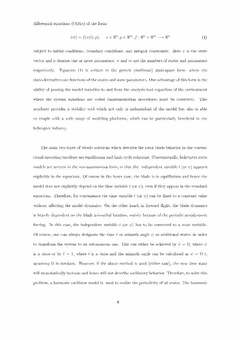
dierential equations (ODEs) of the form:x(t) = f(x(t), p), x ∈ ℜn, p ∈ ℜm, f : ℜn ×ℜm −→ ℜn (1)subje t to initial onditions, boundary onditions, and integral onstraints. Here x is the stateve tor and p denotes one or more parameters. n and m are the numbers of states and parametersrespe tively. Equation (1) is written in the generi (nonlinear) state-spa e form, where thestate-derivatives are fun tions of the states and some parameters. One advantage of this form is theability of passing the model variables to and from the analysis tool regardless of the environmentwhere the system equations are oded (implementation pro edures must be observed). Thisattribute provides a stability tool whi h not only is independent of the model but also is ableto ouple with a wide range of modeling platforms, whi h an be parti ularly bene ial in theheli opter industry.The main two types of steady solutions whi h des ribe the rotor blade behavior in the onven-tional operating envelope are equilibrium and limit y le solutions. Conventionally, heli opter rotormodels are written in the non-autonomous form, in that the independent variable t (or ψ) appearsexpli itly in the equations. Of ourse in the hover ase, the blade is in equilibrium and hen e themodel does not expli itly depend on the time variable t (or ψ), even if they appear in the standardequations. Therefore, for onvenien e the time variable t (or ψ) an be xed to a onstant valuewithout ae ting the model dynami s. On the other hand, in forward ight, the blade dynami sis heavily dependent on the blade azimuthal lo ation, mainly be ause of the periodi aerodynami for ing. In this ase, the independent variable t (or ψ) has to be onverted to a state variable.Of ourse, one an always designate the time t or azimuth angle ψ as additional states, in orderto transform the system to an autonomous one. This an either be a hieved by ψ = Ω, where ψis a state or by t = 1, where t is a state and the azimuth angle an be al ulated as ψ = Ω t,assuming Ω is onstant. However, if the above method is used (either ase), the new time statewill monotoni ally in rease and hen e will not des ribe os illatory behavior. Therefore, to solve thisproblem, a harmoni os illator model is used to realize the periodi ity of all states. The harmoni 8

os illator equations are:hs = hs + Ω hc − hs (h2s + h2c)
hc = −Ω hs + hc − hc (h2s + h2c)
(2)orh′s = hs + hc − hs (h2s + h2c)
h′c = −hs + hc − hc (h2s + h2c)
(3)where the hs = sin(Ω t) = sin(ψ) and hc = cos(Ω t) = cos(ψ) are solutions to Equations (2) and(3). The terms hs and hc an now be used to repla e any sin(Ω t), sin(ψ), cos(Ω t) or cos(ψ)in the blade for ing equations as appropriate. The azimuth angle an be al ulated using thequadrant-ar tangent fun tion ψ = atan2(hs, hc). This approa h to the study of aeroelasti rotorblade dynami s has not previously been attempted, a ording to the literature.III. Aeroelasti Stability of Heli opter Rotor BladesA. Rotor Blade ModelIn this se tion, the use of ontinuation and bifur ation analysis is illustrated in predi ting thestability of heli opter main rotor blades in hover and forward ight onditions. The obje tive ofthis study is to determine how the inherent nonlinearities in a rotating aeroelasti blade manifestthemselves in terms of adverse blade behavior. The nonlinearities in luded in the mathemati almodel were kept to the minimum and in lude geometri , inertial and stru tural terms arising fromthe formulation of the modal equations of a rotating blade, aerodynami s loads in luding stati stall ee t but ex luding dynami stall, and terms arising from oupling with the inow model.Although dynami stall is the primary sour e of nonlinearity, it was not modeled here to fo us onthe analysis of the ee ts of the other sour es. We note, however, that state-spa e representationsof unsteady aerodynami s su h as dynami s stall (e.g. Leishman and Beddoes [32, Goman andKhrabrov [33) are straightforward to in orporate within ontinuation and bifur ation analysis.Modal representation is used for the stru tural blade dynami s and hen e ea h blade isrepresented by a number of general modes (eight in this analysis: four ap, two lag and twotorsional modes). The mode shapes, frequen ies, and modal masses are omputed a priori at a9
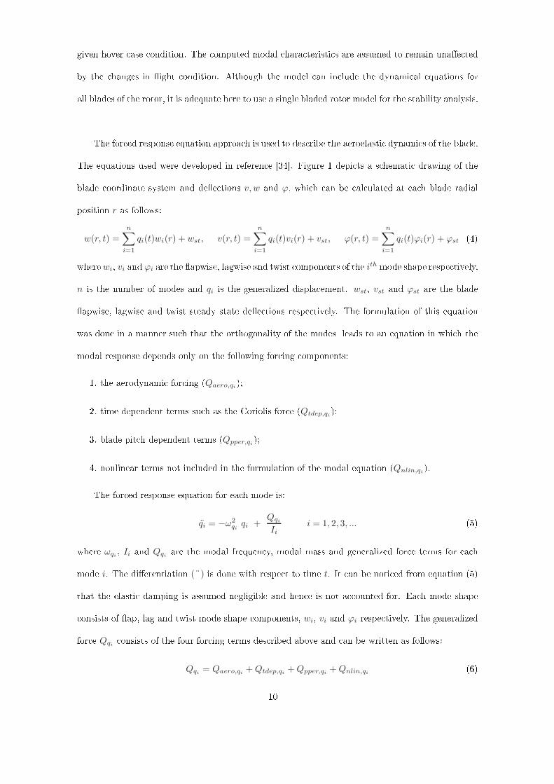
given hover ase ondition. The omputed modal hara teristi s are assumed to remain unae tedby the hanges in ight ondition. Although the model an in lude the dynami al equations forall blades of the rotor, it is adequate here to use a single bladed rotor model for the stability analysis.The for ed response equation approa h is used to des ribe the aeroelasti dynami s of the blade.The equations used were developed in referen e [34. Figure 1 depi ts a s hemati drawing of theblade oordinate system and dee tions v, w and ϕ, whi h an be al ulated at ea h blade radialposition r as follows:w(r, t) =
n∑
i=1
qi(t)wi(r) + wst, v(r, t) =
n∑
i=1
qi(t)vi(r) + vst, ϕ(r, t) =
n∑
i=1
qi(t)ϕi(r) + ϕst (4)where wi, vi and ϕi are the apwise, lagwise and twist omponents of the ith mode shape respe tively.n is the number of modes and qi is the generalized displa ement. wst, vst and ϕst are the bladeapwise, lagwise and twist steady state dee tions respe tively. The formulation of this equationwas done in a manner su h that the orthogonality of the modes leads to an equation in whi h themodal response depends only on the following for ing omponents:1. the aerodynami for ing (Qaero,qi);2. time dependent terms su h as the Coriolis for e (Qtdep,qi);3. blade pit h dependent terms (Qpper,qi );4. nonlinear terms not in luded in the formulation of the modal equation (Qnlin,qi).The for ed response equation for ea h mode is:
qi = −ω2
qiqi +
Qqi
Iii = 1, 2, 3, ... (5)where ωqi , Ii and Qqi are the modal frequen y, modal mass and generalized for e terms for ea hmode i. The dierentiation (¨) is done with respe t to time t. It an be noti ed from equation (5)that the elasti damping is assumed negligible and hen e is not a ounted for. Ea h mode shape onsists of ap, lag and twist mode shape omponents, wi, vi and ϕi respe tively. The generalizedfor e Qqi onsists of the four for ing terms des ribed above and an be written as follows:
Qqi = Qaero,qi +Qtdep,qi +Qpper,qi +Qnlin,qi (6)10

Deformed
Undeformed
i
k
j
k
jFig. 1 S hemati diagram for blade oordinate systems and deformation.where the expressions for the for ing terms an be found in [34. For the aerodynami for ing,a blade element te hnique is used for al ulating the for es and moments a ting on the blades.Quasi-steady aerodynami representation [35 is used for al ulating the aerodynami loads at ea hblade radial station, where the aerodynami oe ients are interpolated from look-up tables fora range of angle of atta k (−180,+180) and Ma h number. It should be noted that the proleof the aerodynami oe ients is nonlinear with Ma h number and angle of atta k in parti u-lar beyond the stall ondition. Blade/blade and blade/airframe intera tions are not onsidered here.The blade deformation due to bending and twisting ae ts the lo al ow velo ities andalso angles of atta k. In general, the omponents of the resultant ow velo ity at ea h bladeelement arise from ve sour es, namely: blade rotation, free stream due to the heli opter move-ment, rotor indu ed velo ity, rates of blade bending and rates of hange of the pre-deformedblade oordinates. Furthermore, the resultant ow velo ity is onventionally resolved into omponents tangential and normal to the lo al axes of the blade. The full expressions of these omponents depend on many variables, in luding the positions of the blade elements before andafter deformation, and an be very long. Hen e, they are not presented here but an be found in [34.The aerodynami for ing Qaero,qi in Equation (6) is the most omplex term to evaluate in omparison to the rest of the for ing terms. This is due to the ompli ated nature of the ow eld11

around the aerofoil se tion. The general form of Qaero,qi is given by the integral:Qaero,qi =
∫ R
0
[
d(L− L0)
drwi +
d(D +D0)
drvi +
d(M −M0)
drϕi
]
dr (7)where the three terms on the right hand side represent the for e distribution in the apwise andlagwise dire tion and the pit hing moment distribution respe tively. These terms are fun tions ofthe ow and blade properties, as well as blade ontrol angles.The rotor instantaneous thrust Ti an be evaluated simply by summing all elemental verti alfor es L and multiplying this by the number of blades NB. i.e.Ti = NB
N∑
elem=1
L (8)where N is the number of blade elements. This value of thrust is only used to estimate the indu edvelo ity within the rotor model. The thrust value used for performan e and trimming pro edureshas to be averaged out a ross one rotor revolution.Tav =
1
2π
∫
2π
0
Ti dψ (9)The inow is aptured via a 3-state Pitt-Peters dynami wake model [3638. This model permitsthe variations of the indu ed velo ity in both the radial and azimuthal position. Furthermore, itallows the lag dynami s asso iated with moving a volume of air to be modeled. The inow modelis given for three states asνi (r, ψ) = ν0 +
r
R(νssin(ψ) + νc cos(ψ)) (10)where νi is the indu ed velo ity at an element of radius r and azimuth position ψ. The indu edvelo ity omponents ν0, νs and νc are given in the wind axes by:
[τ ]
ν0
νs
νc
w
= −
ν0
νs
νc
w
+ [Λ]
Taero
Laero
Maero
w
. (11)Taero, Laero and Maero are the thrust and the aerodynami rolling and pit hing moments respe -tively in the wind axes, and expressions for the matri es [τ ] and [Λ] an be found in [3638.12
Finally, the main model equations, whi h are represented by Equations (2), (5) and (11), anbe rearranged in terms of time derivatives of the state ve tor x to produ e the required state-spa eform:x = f(x, p) where x = hs, hc, ν0, νs, νc, q1, q1, . . . , q8, q8
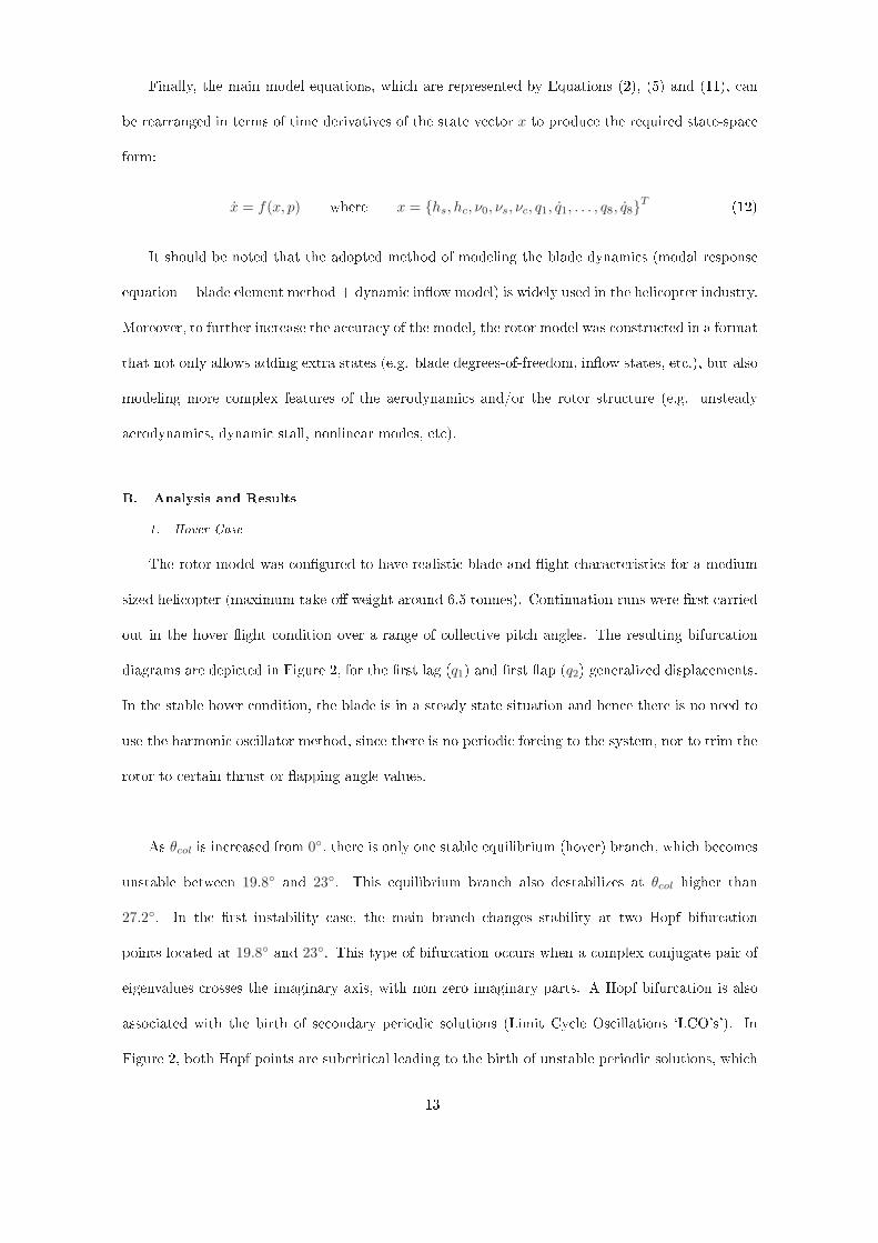
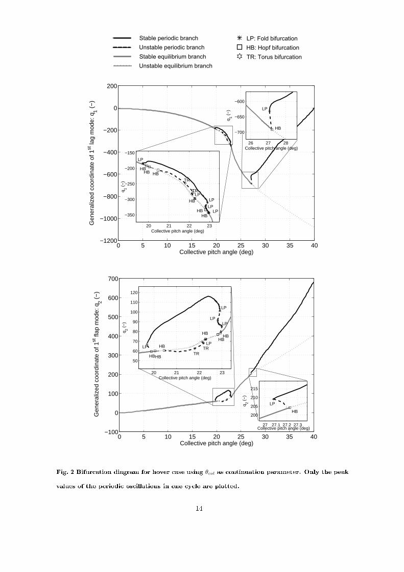
T (12)It should be noted that the adopted method of modeling the blade dynami s (modal responseequation + blade element method + dynami inow model) is widely used in the heli opter industry.Moreover, to further in rease the a ura y of the model, the rotor model was onstru ted in a formatthat not only allows adding extra states (e.g. blade degrees-of-freedom, inow states, et .), but alsomodeling more omplex features of the aerodynami s and/or the rotor stru ture (e.g. unsteadyaerodynami s, dynami stall, nonlinear modes, et ).B. Analysis and Results1. Hover CaseThe rotor model was ongured to have realisti blade and ight hara teristi s for a mediumsized heli opter (maximum take-o weight around 6.5 tonnes). Continuation runs were rst arriedout in the hover ight ondition over a range of olle tive pit h angles. The resulting bifur ationdiagrams are depi ted in Figure 2, for the rst lag (q1) and rst ap (q2) generalized displa ements.In the stable hover ondition, the blade is in a steady state situation and hen e there is no need touse the harmoni os illator method, sin e there is no periodi for ing to the system, nor to trim therotor to ertain thrust or apping angle values.As θcol is in reased from 0, there is only one stable equilibrium (hover) bran h, whi h be omesunstable between 19.8 and 23. This equilibrium bran h also destabilizes at θcol higher than27.2. In the rst instability ase, the main bran h hanges stability at two Hopf bifur ationpoints lo ated at 19.8 and 23. This type of bifur ation o urs when a omplex onjugate pair ofeigenvalues rosses the imaginary axis, with non zero imaginary parts. A Hopf bifur ation is alsoasso iated with the birth of se ondary periodi solutions (Limit Cy le Os illations `LCO's'). InFigure 2, both Hopf points are sub riti al leading to the birth of unstable periodi solutions, whi h13
Stable periodic branch
Unstable periodic branch
Stable equilibrium branch
Unstable equilibrium branch
LP: Fold bifurcation
HB: Hopf bifurcation
TR: Torus bifurcation
0 5 10 15 20 25 30 35 40−1200
−1000
−800
−600
−400
−200
0
200
Collective pitch angle (deg)
Gen
eral
ized
coo
rdin
ate
of 1
st la
g m
ode:
q1 (
−)
26 27 28
−700
−650
−600
Collective pitch angle (deg)
q 1 (−
)
HB
LP
20 21 22 23
−350
−300
−250
−200
−150
HB
Collective pitch angle (deg)
q 1 (−
)
HB HB HB
HB
HB
LP LP
LP
LP
LP TR
TR
0 5 10 15 20 25 30 35 40−100
0
100
200
300
400
500
600
700
Collective pitch angle (deg)
Gen
eral
ized
coo
rdin
ate
of 1
st fl
ap m
ode:
q2 (
−)
20 21 22 23
50
60
70
80
90
100
110
120
HB
Collective pitch angle (deg)
q 2 (−
)
HB
HB HB
HB HB
LP LP
LP
LP LP
TR TR
27 27.1 27.2 27.3
200
205
210
215
Collective pitch angle (deg)
q 2 (−
)
HB
LP
Fig. 2 Bifur ation diagram for hover ase using θcol as ontinuation parameter. Only the peakvalues of the periodi os illations in one y le are plotted.14
o-exist with se tions of the stable equilibrium bran h. A sub riti al Hopf is a hard bifur ationwhi h will lead to the solutions jumping to another attra tor just after the bifur ation point. Thisjump an be very dangerous parti ularly if this latter attra tor is far from the original bran h.This is be ause the divergen e of the transient os illatory response, just after the Hopf, an bevery rapid and it may not be possible to go ba k to the stable equilibrium solution, just before theHopf point, by modest variation of the system parameters, or without signi ant hysteresis ee ts.The unstable periodi bran h emerging from the Hopf point at θcol = 19.8 extends very slightlyas θcol is redu ed and then it folds ba k at a limit point (fold bifur ation) at θcol = 19.6. Thisbifur ation point o urs when one Floquet multiplier rosses the unit ir le at a value of 1. Thesolution then be omes stable and extends as θcol is in reased. Furthermore, this stable periodi bran h hanges stability a few times in the vi inity of θcol = 23 due to the existen e of threeother fold bifur ation points, until it merges with the main equilibrium bran h at the Hopf pointlo ated at θcol = 23. It an be shown that if the blade is disturbed from the unstable equilibriumbran h, it will always get attra ted to the stable periodi bran h. In other words, if the pit h an-gle is between 19.8 and 23, the blade will eventually behave in a periodi manner, i.e. LCO's o ur.The Hopf point at θcol = 19.8 is found to be asso iated with the rst ap mode be omingunstable, whi h stabilizes again at θcol = 23. It was also found that two other ap modes loseand gain stability within the same range of olle tive pit h angles. This is depi ted by four otherHopf bifur ation points within the unstable equilibrium bran h. The unstable periodi bran hwhi h emerges from two of these points is plotted in Figure 2. This bran h also experien es torus(Neimark-Sa ker) bifur ations, whi h will introdu e limit y les of higher period or - more likely -quasi-periodi solutions.Figure 2 also illustrates the existen e of a sub riti al Hopf and limit point bifur ation, whi hfold the se ondary unstable periodi bran h into a stable periodi one. If the olle tive pit h angleis in reased beyond 27.23, the solutions will jump to the stable periodi bran h. It an also beseen that in the range θcol = 27.07 to 27.23 the blade an behave either in a stable equilibrium15

or in a stable periodi manner, depending on the perturbation levels subje ted to the blade.The maximum operating olle tive pit h angle for this heli opter is about 12 and hen e itis well within the stable region. Although the blade behavior is expe ted to be stable for thisoperating heli opter onguration, the above results are useful in supporting the argument that thenonlinear dynami s of the aeroelasti rotating blade does not introdu e any se ondary bran hesthat extend ba k to the operating olle tive pit h range. This is be ause of the fold bifur ationsof the periodi bran hes that emerged from the sub riti al Hopf bifur ation points at θcol = 19.8and 27.23. Additional simulation results onrmed that there are no isolated se ondary bran heswithin the operating olle tive pit h range. Finally, although the bifur ation points o urred wellabove the 12 limit, this ase study provides a good example of how important the onstru tionof the bifur ation diagram is in predi ting the global nonlinear dynami s of the blade behavior.In ontrast, the traditional stability analysis fo uses only on examining the stability of the mainbran h typi ally using eigen analysis or Floquet methods, without properly onsidering the ee tsof large perturbations. Although, time history simulation an be used to address this shortfall, it isdi ult to obtain a lear pi ture of the underlying stru ture of the nonlinear dynami s, espe iallywhen unstable se ondary bran hes exist in the vi inity of the main solution bran h. In additions,for ases where the system is poorly damped, running a large number of time simulations be omesvery time expensive.Finally, for a more omplete investigation, the dependen e on other parameters would also needto be studied using the ontinuation and bifur ation analysis. However, for rotor blade aeroelasti ityproblems, there is at least a moderate number of parameters that an ae t the blade stability, forexample blade stru tural and inertial properties, blade ontrol angles and ow parameters. Runningthe ontinuation analysis to over the whole parameter spa e an be very time expensive or evenprohibitive. One solution to this problem is to pi k one parameter as the ontinuation parameterwhile onstraining the others to satisfy a ertain ondition as the ontinuation analysis is performed.This method is illustrated in the next se tion, where the trim ondition was sele ted as a onstraint16

for the forward ight ase.2. Forward Flight CaseUnlike many analyses, where rotor trimming is arried out rst (using the harmoni balan emethod for example) prior to any stability al ulations, some ontinuation and bifur ation toolssu h as AUTO an ompute solutions and their stability simultaneously for given boundary orintegral onditions. This means that the ontinuation and trimming pro edure an be done inparallel. In fa t, the eigenvalues and Floquet multipliers are omputed at negligible extra ost to the ontinuation analysis. In addition, the ontinuation methods used in this work does not require to onstrain the periodi solutions to a xed number of harmoni s. Therefore, more a urate solutionsas well as trim an be obtained. To a hieve rotor thrust and hub moments trim in forward ight,three integral onditions were imposed. The propulsive trim ondition to balan e the propulsivefor e with heli opter drag was not expli itly imposed during the ontinuation. Instead, the rotorshaft in lination was interpolated based on a pre-supplied prole for a range of advan e ratio of0 < µ < 0.45. For higher values of µ, the shaft angle was xed. The boundary onditions an be onstru ted as follows:1. The thrust trim ondition: in this ondition the blade olle tive pit h angle θcol is obtainedby equating the average al ulated thrust in one rotor revolution to the required thrust:
Tav =1
2π
∫
2π
0
Ti dψ = Treq (13)2 & 3. Hub moment or ap angle trim onditions: these onditions allow the determination of therequired y li pit h angles (Alat and Blong) to a hieve the desired trim. For ap trim, therst harmoni ap omponents in longitudinal and lateral dire tions an be equated to therequired values. This an be implemented as follows:1
π
∫
2π
0
β sin(ψ) dψ =1
π
∫
2π
0
β hs dψ = βa1,req (14)1
π
∫
2π
0
β cos(ψ) dψ =1
π
∫
2π
0
β hc dψ = βb1,req (15)17

Figure 3 illustrates the ontinuation results when the advan e ratio is used as the ontinuationparameter for two rotor dis loading onditions: light and heavy loading onditions. The thrustgenerated in the heavy loading ondition is about 75% more of that in the light weight ase. Onlythe peak values of os illatory modal displa ements of the rst two modes are plotted. For the lightweight ase, the bifur ation diagrams show that when µ is between approximately 1.03 and 1.19 theperiodi bran h is unstable, due to the presen e of two torus bifur ations. Whereas, the instabilityo urs at a lower value of µ ≈ 0.82 for the other ase. To further s rutinize the results, the variationof the damping of the modes was investigated from the omputed Floquet multipliers. It was foundthat the unstable periodi bran h orresponds to the range of advan e ratios when the damping ofthe rst lag mode (mode 1) is negative. Hen e, this indi ates that this instability an be of theap-lag type.Stable periodic branch
Unstable periodic branch
TR: Torus bifurcation
0 0.2 0.4 0.6 0.8 1 1.2 1.4 1.5−200
−150
−100
−50
0
50
100
Advance ratio µ
Max
gen
eral
ized
coo
rdin
ate
of 1
st la
g m
ode:
q1 (
−)
TR TR
Heavy weight condition
Light weight condition
TR
0 0.2 0.4 0.6 0.8 1 1.2 1.4 1.50
50
100
150
200
250
300
350
400
450
Advance ratio µ
Max
gen
eral
ized
coo
rdin
ate
of 1
st fl
ap m
ode:
q2 (
−)
TR
TR
TR
Light weight condition
Heavy weight condition
Fig. 3 Bifur ation diagram for forward ight ase using µ as ontinuation parameter. Onlythe peak values of the os illations in one y le are plotted.It should be noted that although the mathemati al model might not be valid for very highadvan e ratios ( µ > 0.8 for example) and the heli opter might not y at µ > 0.55, it is ustomarywhen performing ontinuation analysis to extend the ontinuation parameter beyond the physi alrange. The reason for this is to sear h for any bifur ation points - espe ially those sub riti alones - that might lead to new solution bran hes, whi h return ba k into the physi al range.Although ontinuation methods that follow quasi-periodi bran hes exist, the examination of the18
emerging quasi-periodi bran hes from the torus bifur ations here were done through a series oftime simulation runs. For the light weight ase depi ted in Figure 3, the only se ondary bran hfound was a stable quasi-periodi bran h (not shown in Figure 3), whi h is ontained in the range1.03 ≤ µ ≤ 1.19 and onne ts the two super riti al torus bifur ations points. Similarly for the se -ond loading ase, a stable quasi-periodi bran h extends from the torus bifur ation at µ ≈ 0.82 within reasing values of advan e ratio, most likely to re onne t with another torus bifur ation at µ > 1.5.Figure 3 illustrates that in reasing the rotor dis loading an lead to instability o urring ata lower value of advan e ratio. Therefore, it an be argued that for very high loading onditionsif the presen e of additional sour es of nonlinearity auses the torus bifur ations to hange their riti ality, unstable quasi-periodi bran hes may extend ba k to the operating heli opter speedrange. Hen e, the proper identi ation of these se ondary solutions be omes essential. Finally,although the ontinuation analysis was not used to follow the se ondary quasi-periodi bran hes,the methods proved very e ient in ombining trimmed-ight solutions with the stability analysisand identifying the types of the bifur ation points. Furthermore, the implementation of the harmoni os illator model for studying rotating blade aeroelasti problems was demonstrated. This te hniqueallows the ontinuations analysis to follow periodi solutions in luding those arising from perioddoubling bifur ations. The implementation of the harmoni os illator is useful for investigating notonly the aeroelasti stability of a passive blade but also when additional for ing is present su h asthat of an a tuated trailing edge ap.IV. Aeroelasti Stability of Heli opter Rotor Blades with Trailing Edge FlapsA tive Trailing Edge Flaps (TEF) are re ognized as ee tive means for redu ing rotor-indu edvibrations. However, the intera tion between the blade and TEF dynami s might give rise toinstability. Furthermore, determining the ee ts of the a tivated ap on the blade dynami hara teristi s an be a hallenging task, in parti ular with the in reased level of nonlinearityof the oupled blade/TEF/a tuator/ ontroller system. In this ase study, the ontinuation andbifur ation tools were oupled with an industrial heli opter rotor ode to investigate the nonlinear19

A
B
C
A: Feathering axis
B: Flap hinge
C: Flap centre of gravityFig. 4 S hemati diagram of the trailing edge ap.stability of a passive trailing edge ap in orporated in a exible rotor blade. The aim is toinvestigate if the inherent nonlinearity in the blade/TEF system an result in unstable behavioreven without in luding any stru tural or ontrol nonlinearities to the TEF system. Hen e, thisstudy extends the urrent knowledge on the stability of rotor blade trailing edge aps to un overtheir inuen e on the oupled blade/ap nonlinear dynami s.The stru ture of the rotor model is very similar to that des ribed in Case 1, in that a modalapproa h is used for des ribing the dynami s of the exible blade where ea h blade is represented byeight general modes (four ap, two lag and two torsional modes). The olle tive pit h angle was setto an operating hover ase value, where the blades' modes are well damped. The TEF was modeledas a rigid ontrol surfa e hinged at a hordwise distan e xb from the leading edge of the blade, seeFigure 4. The stru tural atta hments of the TEF system to the rest of the blade and the drivinga tuator in the passive mode (δac = 0) were represented by a linear rotational stiness quantity(ktef ), whi h was assumed to a t at the ap hinge. The enter of gravity (C.G.) of the ap is atdistan e xc from the ap hinge. Be ause of the aerodynami and inertial ouplings between the apand the blade dynami s the governing dierential equations were re-arranged to allow writing themin the state-spa e form (no a eleration terms on the right-hand-side of the equations).The parameters of interest in this study are the TEF hinge stiness and the ap enter of20

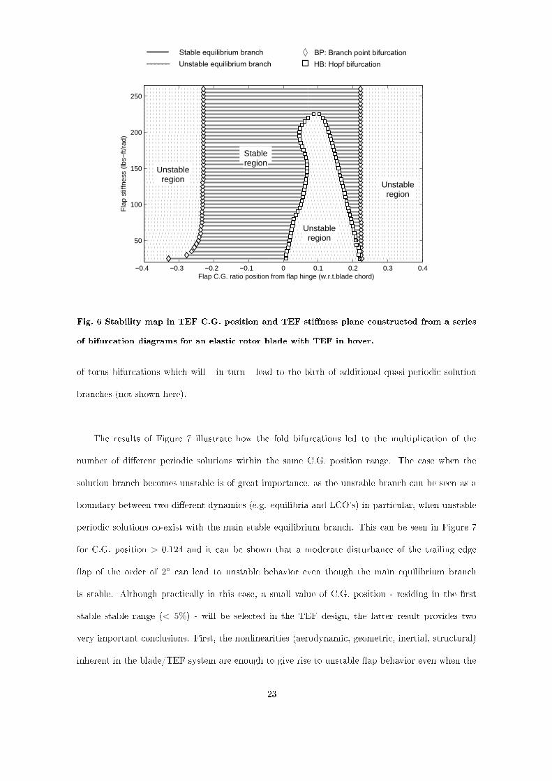
gravity (C.G.) position from the ap hinge. The variation of these two parameters was shown inthe literature [27 to ae t the linear stability of the ap/blade system and hen e bifur ation points an be lo alized. The ap hinge stiness represents both the stru tural spring stiness at the hingeand the stiening ee ts of the TEF a tuator omponents and linkages (in passive mode). Themodel of the TEF stiness was purposefully hosen to be linear for two reasons. First, linear (orquasi-linear) stiness is su ient to obtain the standard lo al stability of the main bran h. Se ond,using a linear TEF stiness allows us to show whether or not the ri h TEF dynami s (bifur ationsand se ondary (periodi ) bran hes) is entirely due to the sour es of nonlinearity inherent in the oupled blade/TEF system and not be ause of the ap stiness itself. Although, it is not investi-gated here, it an be argued that additional nonlinearity in the ap stiness or a tivating the ap an introdu e new bifur ations and/or may hange the stru ture of the se ondary solution bran hes.Figure 5 presents the bifur ation diagram for the TEF angle δ when the ap C.G. position isused as the ontinuation parameter. Although the ap hord is only 15% of the total blade hord,the ontinuation was run up to 50% of the blade hord. This was to sear h for any bifur ationthat may exist outside but lose to the physi al parameter range. The results show the existen eof three bifur ation points: two Hopf bifur ations and one bran h point bifur ation. This latteris an indi ation of a divergen e s enario, whereas the Hopf bifur ations are related to utter orutter-like instability. It is evident that unstable onditions an arise in the physi al limits of C.G.ratio, and that the instability at C.G. ratio of ir a 0.22 ould potentially give rise to a solutionbran h that extends ba k into the physi al range.The lo ation of the bifur ation points will vary with other parameters. A series of ontinuationruns was therefore performed using the ap C.G. position as the ontinuation parameter for dierenthinge stiness values. The ombined bifur ation diagrams were plotted as a proje tion plot in atwo-parameter plane (see Figure 6). This plot illustrates how the ap C.G. position and stinessparameter plane an be divided into stable and unstable regions, where the bifur ation pointstra e the stability boundaries. These boundaries an also be omputed dire tly via 2-parameter21

Stable equilibrium branch
Unstable equilibrium branch
BP: Branch point bifurcation
HB: Hopf bifurcation
0 0.05 0.1 0.15 0.2 0.25 0.3 0.35 0.4 0.45 0.5−0.05
0
0.05
0.1
0.15
0.2
0.25
0.3
0.35
HB
HB
BP
Flap C.G. position ratio from flap hinge (w.r.t. chord)
Tra
iling
edg
e fla
p an
gle
(deg
)
Fig. 5 Bifur ation diagram for an elasti rotor blade with TEF in hover over TEF C.G.position, for ap stiness of 200 lbs-ft/rad. ontinuation runs, where the solutions generated are onstrained to mat h the bifur ation riteria(Hopf or bran h point bifur ation in this ase). Note that this stability map in parameter spa erefers to the stability of the main solution surfa e as shown in the Figure 5 and not of anyother solution bran hes arising from bifur ation points. It an be seen that the stable TEF C.G.range de reases for low ap stiness values. An example s enario where the ap stiness an bedramati ally redu ed is the failure ase of the TEF a tuator (zero stiness).Finally, ontinuation runs were performed to tra e the periodi bran hes emerging from theHopf bifur ations. Figure 7 illustrates the results of these runs in the form of a more ompletebifur ation diagram ompared to that of Figure 5. It an be seen that periodi behavior of theap is quite omplex and is subje ted to dierent types of bifur ations, in luding folds (limitpoints) and torus bifur ations. There exist a number of stable LCO segments where some of thesegments o-exist over the same C.G position range. This means that the ap as well as the blade an os illate in two or more dierent forms for the same value of C.G. position, depending onlyon initial onditions. Furthermore, it an be seen that the periodi bran h undergoes a number22
Stable equilibrium branch
Unstable equilibrium branch
BP: Branch point bifurcation
HB: Hopf bifurcation
−0.4 −0.3 −0.2 −0.1 0 0.1 0.2 0.3 0.4
50
100
150
200
250
Flap C.G. ratio position from flap hinge (w.r.t.blade chord)
Fla
p st
iffne
ss (
lbs−
ft/ra
d)
Unstableregion
Unstableregion
Unstableregion
Stableregion
Fig. 6 Stability map in TEF C.G. position and TEF stiness plane onstru ted from a seriesof bifur ation diagrams for an elasti rotor blade with TEF in hover.of torus bifur ations whi h will - in turn - lead to the birth of additional quasi-periodi solutionbran hes (not shown here).The results of Figure 7 illustrate how the fold bifur ations led to the multipli ation of thenumber of dierent periodi solutions within the same C.G. position range. The ase when thesolution bran h be omes unstable is of great importan e, as the unstable bran h an be seen as aboundary between two dierent dynami s (e.g. equilibria and LCO's) in parti ular, when unstableperiodi solutions o-exist with the main stable equilibrium bran h. This an be seen in Figure 7for C.G. position > 0.124 and it an be shown that a moderate disturban e of the trailing edgeap of the order of 2 an lead to unstable behavior even though the main equilibrium bran his stable. Although pra ti ally in this ase, a small value of C.G. position - residing in the rststable stable range (< 5%) - will be sele ted in the TEF design, the latter result provides twovery important on lusions. First, the nonlinearities (aerodynami , geometri , inertial, stru tural)inherent in the blade/TEF system are enough to give rise to unstable ap behavior even when the23

main equilibrium bran h is stable. Additional nonlinear properties of the TEF system (in ludingthe ap, a tuator and ontrol law) may lead to a ri her bifur ation diagram, with possible se ondaryunstable bran hes extending ba k to small values of ap C.G. positions. Se ond, the ontinuationand bifur ation methods are very powerful in un overing the stru ture of the TEF dynami s as onventional stability analysis would not provide this information. This is parti ularly useful whenresponses under transient onditions are di ult to predi t when there are multiple attra tors;however, the bifur ation diagrams show learly where further studies - in orporating time historyruns - are needed and, indeed, how to interpret the results thereof.Stable periodic branch
Unstable periodic branch
Stable equilibrium branch
Unstable equilibrium branch
LP: Fold bifurcation
HB: Hopf bifurcation
TR: Torus bifurcation
BP: Branch point bifurcation
0 0.02 0.04 0.06 0.08 0.1 0.12 0.14 0.16 0.18 0.2−0.5
0
0.5
1
1.5
2
2.5
3
3.5
4
4.5
LP
LP
LP
LP
LP TR
LP
TR TR
LP TR LP
LP
TR TR
LP BP
BP
Flap C.G. ratio position from flap hinge (w.r.t. chord)
Max
trai
ling
edge
flap
ang
le (
deg)
HB HB
LP LP
TR
Fig. 7 Bifur ation diagram for an elasti rotor blade with TEF in hover over TEF C.G.position, for ap stiness of 200 lbs-ft/rad. Only the peak values of the periodi os illationsin one y le are plotted.24
V. Con lusionThis paper presented new implementations of bifur ation and ontinuation methods instudying the nonlinear heli opter aeroelasti blade stability with and without trailing edge aps.The aeroelasti model was onstru ted in a generi state spa e form. Initially, the analysis wasapplied to investigate the aeroelasti stability of a exible rotor blade for a range of olle tivepit h angles. The results illustrated that even in the hover ase the global nonlinear dynami sof the blade are quite omplex, giving rise to stable and unstable periodi bran hes. However,the heli opter onguration used in this ase was very stable whi h resulted in the nonlinear hara teristi s inherent in the rotating blade to take ee t outside the operating olle tive pit hrange. Nevertheless, the results showed how unstable limit y le bran hes o-existed with themain stable equilibrium bran h. Additional nonlinearities may extend these unstable bran hes loser to the operating olle tive pit h angle range. Two forward ight ases were also shownrequiring implementation using a harmoni os illator to impose the ne essary periodi ally for ed ondition. This exhibited nonlinear behavior beyond the operating envelope of the heli opter,although relatively lose to the higher speed regions for the heavy weight ase. The e ien yof the te hnique in ombining trimmed-ight solutions with the stability analysis was demonstrated.The study was then extended to address the nonlinear stability of a passive trailing edgeap in orporated in the elasti blade for the hover ase. It was shown that not only were thestability boundaries for the trailing edge ap omputed using the ontinuation te hniques, butalso se ondary stable and unstable periodi bran hes were followed. The results predi ted thatunstable periodi bran hes o-exist with the main stable equilibrium bran h for the same values ofap enter of gravity position. This meant that large enough disturban es of the trailing edge ap,of the order of 2, ould lead to unstable behavior even though the main equilibrium bran h isstable. These results illustrate the advantage of using ontinuation and bifur ation methods overthe onventional stability analysis, whi h would fail to provide this type of non-lo al information.The analysis presented in this paper not only illustrates that ontinuation and bifur ation25

methods are appli able to studying the rotating blade aeroelasti stability, but also onrms thatthe dynami s of the blade behavior are very omplex and nonlinear, even in the hover ondition.It was shown that the lo al linearized analysis is not su ient to guarantee the stability of thetrailing edge ap and large but possible perturbations of the order of 2 an lead to undesirabledynami s. Although most of the omplex behavior of the blade was found outside the operationalparameter range for this heli opter, the added omplexity of future rotor systems in luding thoseof the trailing edge systems will introdu e dierent types of nonlinearity that an have adversestability ee ts within the operating parameter spa e and hen e need to be treated with are.Finally, the ontinuation and bifur ation tools were essential in un overing the global blade dynami swhen multiple solutions oexist. Therefore these tools oer onsiderable advantages in aeroelasti stability analyses of future rotor ongurations, in parti ular where new devi es su h as a tivetrailing edge aps, semi-a tive lag dampers and a tive pit h-links introdu e additional nonlinearitiesto the system. VI. A knowledgmentThe authors would like to thank AgustaWestland for funding and supporting of the work pre-sented in this paper. Referen es[1 Horvay, G., Rotor Blade Flapping Motion, Quart. Appl. Math, Vol. 5, No. 2, 1947, pp. 149 167.[2 Horvay, G. and Yuan, S. W., Stability of Rotor Blade Flapping Motion when the Hinges are Tilted:Generalization of the `Re tangular Ripple' Method of Solution, Journal of the Aeronauti al S ien es,Vol. 10, 1947, pp. 583 593.[3 Shutler, A. G. and Jones, J. P., The Stability of Rotor Blade Flapping Motion, Aeronauti al Resear hCoun il, R & M No. 3178, May 1958.[4 Wei, F. and Peters, D., Lag Damping in Autorotation by a Perturbation Method, Pro eedings of theAmeri an Heli opter So iety 34th Annual Forum, Washington, D.C., 1978, pp. 78 25.[5 Peters, D. A., Flap-Lag Stability of Heli opter Rotor Blades in Forward Flight, Journal of Ameri anHeli opter So iety, Vol. 20, No. 4, 1975, pp. 2 13,doi:10.4050/JAHS.20.2. 26

[6 Lowis, O. J., The Stability of Rotor Blade Flapping Motion at High Tip Speed Ratios, Aeronauti alResear h Coun il, R & M No. 3544, January 1963.[7 Peters, D. A. and Hohenemser, K., Appli ation of the Floquet Transition Matrix to Problems of LiftingRotor Stability, Journal of Ameri an Heli opter So iety, Vol. 16, No. 2, 1971, pp. 25 33,doi:10.4050/JAHS.16.25.[8 Friedmann, P. P. and Hodges, D. H., Rotary Wing Aeroelasti ity - A Histori al Perspe tive, Journalof Air raft, Vol. 40, No. 6, 2003, pp. 1019 1046,doi:10.2514/2.7216.[9 Friedmann, P. P., Rotary-Wing Aeroelasti ity: Current Status and Future Trends, AIAA Journal,Vol. 42, No. 10, 2004, pp. 1953 1972,doi:10.2514/1.9022.[10 Kuznetsov, Y., Elements of Applied Bifur ation Theory, Springer-Verlag, 1995, hap. 3 - 5.[11 Sibilski, K., Bifur ation Analysis of a Heli opter Non-Linear Dynami s, Ar hive of Me hani al Engi-neering, Vol. 46, No. 2, 1999, pp. 171 192.[12 Sibilski, K., Nonlinear Flight Me hani s of a Heli opter Analysis by Appli ation of Continuation Meth-ods, Pro eedings of the 25th European Rotor raft Forum, Rome, Italy, 1999.[13 Sibilski, K., A Study of the Flight Dynami s Heli opter Carrying an External Load Using Bifur ationTheory and Continuation Methods, Journal Of Theoreti al And Applied Me hani s, Vol. 41, No. 4,2003, pp. 823852.[14 Bedford, R. G. and Lowenberg, M. H., Use of Bifur ation Analysis in the Design and Analysis of He-li opter Flight Control Systems, Pro eedings of the 29th European Rotor raft Forum, Friedri hshafen,Germany, 2003.[15 Bedford, R. and Lowenberg, M., Bifur ation Analysis of Rotor raft Dynami s with an UnderslungLoad, AIAA Atmospheri Flight Me hani s Conferen e, Providen e, RI, Vol. 1, 2004, pp. 595 619,doi:10.2514/6.2004-4947.[16 Bedford, R. G. and Lowenberg, M. H., Flight Dynami s Analysis of Periodi ally For ed Rotor raftModel, AIAA Atmospheri Flight Me hani s Conferen e, Keystone, CO, Vol. 2, 2006, pp. 1210 1228,doi:10.2514/6.2006-6634.[17 Maradakis, G., Fundamental Nonlinear Chara teristi s of Heli opter Flight Me hani s, M.Phil. Thesis,Department of Applied Mathemati s, Glasgow Caledonian University, Glasgow, 2000.[18 Mokrane, A., Heli opter Ground Resonan e Predi tion Using an Integrated Nonlinear Model, Ph.D.Dissertation, Department of Aerospa e Engineering, University of Bristol, Bristol, UK, 2011.27

[19 Avanzini, G. and De Matteist, G., Ee ts of Nonlinearities on Ground Resonan e Instability, Pro eed-ings of the 34th European Rotor raft Forum, Liverpool, UK, Vol. 3, 2008, pp. 2327 2378.[20 Basset, P.-M. and Prasad, J., Study of the Vortex Ring State using Bifur ation Theory, Pro eedingsof the Ameri an Heli opter So iety 58th Annual Forum, Montreal, Canada, 2002.[21 Rezgui, D., Lowenberg, M. H., and Bunniss, P. C., Experimental and Numeri al Analysis of theStability of an Autogyro Teetering Rotor, Pro eedings of the Ameri an Heli opter So iety 64th AnnualForum, Montréal, Canada, 2008.[22 Rezgui, D., Lowenberg, M. H., and Bunniss, P. C., A Combined Numeri al/Experimental ContinuationApproa h Applied to Nonlinear Rotor Dynami s, Progress in Industrial Mathemati s at ECMI 2008,Springer Berlin Heidelberg, Mathemati s in Industry, pp. 169174, 2010,doi:10.1007/978-3-642-12110-4_21.[23 Lowenberg, M. H., Rezgui, D., and Bunniss, P. C., Experimental Evaluation of Numeri al Continuationand Bifur ation Methods Applied to Autogyro Rotor Blade Aerome hani al Stability, Pro eedings ofthe ASME 2009 International Design Engineering Te hni al Conferen es & Computers and Informationin Engineering Conferen e, San Diego, USA, 2009.[24 Rezgui, D., Lowenberg, M. H., Jones, M., and Monteggia, C., Appli ation of Continuation and Bifur- ation Methods to Aeroelasti Rotor Blade Stability, Pro eedings of 37th European Rotor raft Forum,Milan, Italy, 2011.[25 Roth, D., Enenkl, B., and Dieteri h, O., A tive Rotor Control by Flaps for Vibration Redu tion - FullS ale Demonstrator and First Flight Test Results, Pro eedings of the 32nd European Rotor raft Forum,Maastri ht, Netherlands, Vol. 2, 2007, pp. 801 814.[26 Dieteri h, O., Enenkl, B., and Roth, D., Trailing Edge Flaps for A tive Rotor Control Aeroelasti Chara teristi s of the ADASYSRotor System, Pro eedings of Ameri an Heli opter So iety 62nd AnnualForum, Phoenix, AZ, Vol. 2, 2006, pp. 965 986.[27 Shen, J. and Chopra, I., Aeroelasti Stability of Trailing-Edge Flap Heli opter Rotors, Journal of theAmeri an Heli opter So iety, Vol. 48, No. 4, 2003, pp. 236 243,doi:10.4050/JAHS.48.236.[28 Mauri e, J.-B., King, F., Fi hter, W., Dieteri h, O., and Konstanzer, P., Floquet Convergen e Analysisfor Periodi A tive Rotor Systems Equipped with Trailing Edge Flaps, Pro eedings of the 35th EuropeanRotor raft Forum, Hamburg, Germany, Vol. 2, 2009, pp. 701 714.[29 Straub, F. and Charles, B., Aeroelasti Analysis of Rotors with Trailing Edge Flaps Using Compre-hensive Codes, Journal of the Ameri an Heli opter So iety, Vol. 46, No. 3, 2001, pp. 192 199,28
doi:10.4050/JAHS.46.192.[30 Doedel, E. J., Oldeman, B. E., Champneys, A. R., Der ole, F., Fairgrieve, T. F., Kuznetsov, Y. A.,Paenroth, R. C., Sandstede, B., Wang, X. J., and Zhang, C., AUTO-07P : Continuation and Bi-fur ation Software for Ordinary Dierential Equations, Te h. rep., Con ordia University, Montreal,Canada, 2009. Http://indy. s. on ordia. a/auto/.[31 Coetzee, E., Krauskopf, B., and Lowenberg, M., The Dynami al System Toolbox: Integrating AUTOinto MATLAB, The 16th US National Congress of Theoreti al and Applied Me hani s, State College,Pennsylvania, Vol. USNCTAM2010-827, July 2010.[32 Leishman, J. and Beddoes, T., A Semi-empiri al Model for Dynami Stall, Journal of the Ameri anHeli opter So iety, Vol. 34, No. 3, 1989, pp. 3 17,doi:10.4050/JAHS.34.3.[33 Goman, M. and Khrabrov, A., A State-Spa e Representation of Aerodynami Chara teristi s of anAir raft at High Angles of Atta k, Journal of Air raft, Vol. 31, No. 5, 1994, pp. 1109 1115,doi:10.2514/3.46618.[34 Chan, W., A Coupled Rotor-Fuselage Aeroelasti Analysis Using Complex Rotor Modes, Ph.D. Disser-tation, City University, London, 1996.[35 Bielawa, R. L., Rotary Wing Stru tural Dynami s and Aeroelasti ity, AIAA edu ation series, Ameri anInstitute of Aeronauti s and Astronauti s, 2006, pp. 343 - 347.[36 Pitt, D. and Peters, D., Theoreti al Predi tion of Dynami Inow Derivatives, Verti a, Vol. 5, No. 1,1981, pp. 21 34.[37 Peters, D. A. and HaQuang, N., Dynami Inow for Pra ti al Appli ations, Journal of Ameri anHeli opter So iety, Vol. 33, No. 4, 1988, pp. 64 68,doi:10.4050/JAHS.33.64.[38 Gaonkar, G. and Peters, D., Review of Dynami Inow Modelling for Rotor raft Flight Dynami s,Verti a, Vol. 12, No. 3, 1988, pp. 213 242.
29