printed circuit boards the design process. what is the output? not just a pcb engineering drawing...
TRANSCRIPT
Printed Circuit Boards
The Design Process
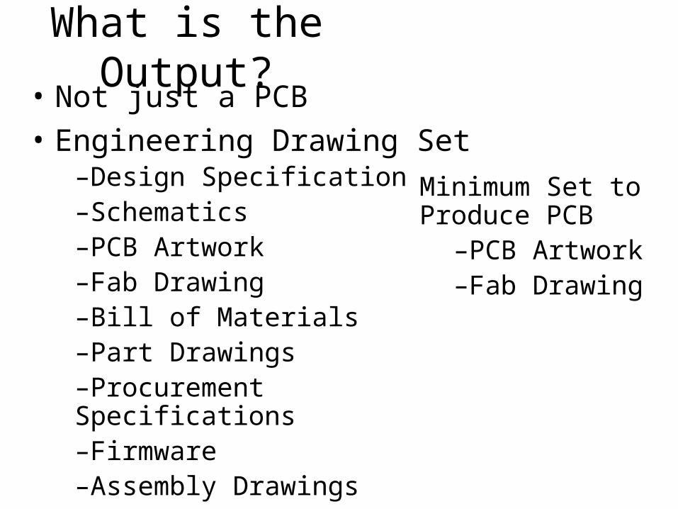
What is the Output?• Not just a PCB
• Engineering Drawing Set–Design Specification–Schematics–PCB Artwork–Fab Drawing–Bill of Materials–Part Drawings–Procurement Specifications–Firmware–Assembly Drawings–Test Specifications
Minimum Set to Produce PCB
–PCB Artwork–Fab Drawing
PCB Artwork
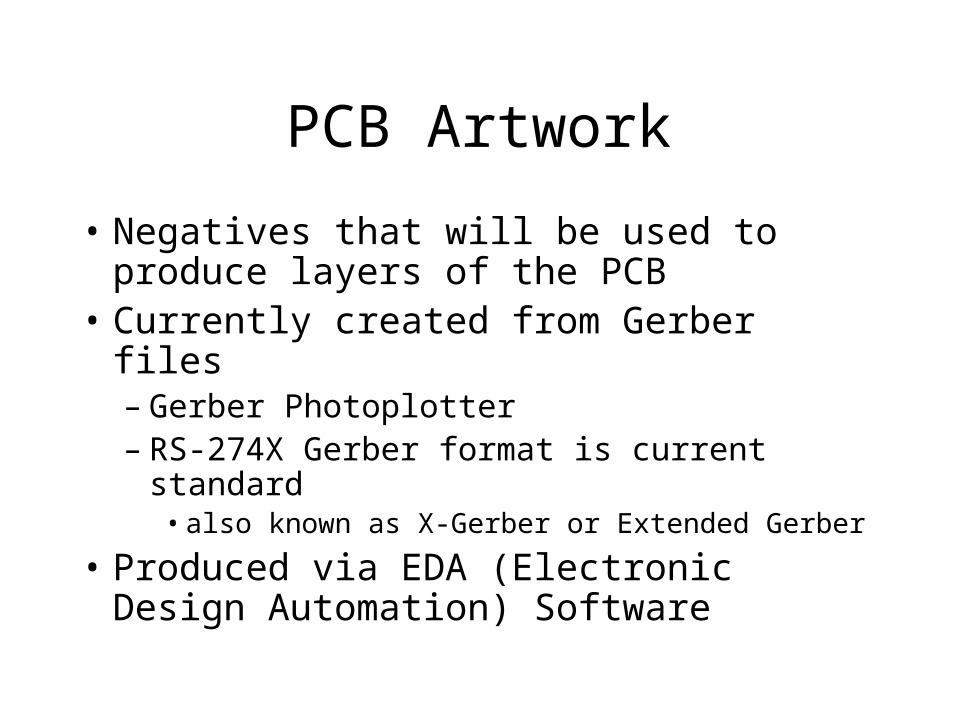
• Negatives that will be used to produce layers of the PCB
• Currently created from Gerber files– Gerber Photoplotter– RS-274X Gerber format is current standard
• also known as X-Gerber or Extended Gerber
• Produced via EDA (Electronic Design Automation) Software
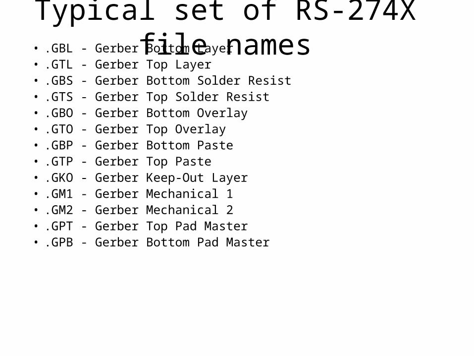
Typical set of RS-274X file names• .GBL - Gerber Bottom Layer• .GTL - Gerber Top Layer• .GBS - Gerber Bottom Solder Resist• .GTS - Gerber Top Solder Resist• .GBO - Gerber Bottom Overlay• .GTO - Gerber Top Overlay• .GBP - Gerber Bottom Paste• .GTP - Gerber Top Paste• .GKO - Gerber Keep-Out Layer• .GM1 - Gerber Mechanical 1• .GM2 - Gerber Mechanical 2• .GPT - Gerber Top Pad Master• .GPB - Gerber Bottom Pad Master
NC Drill File
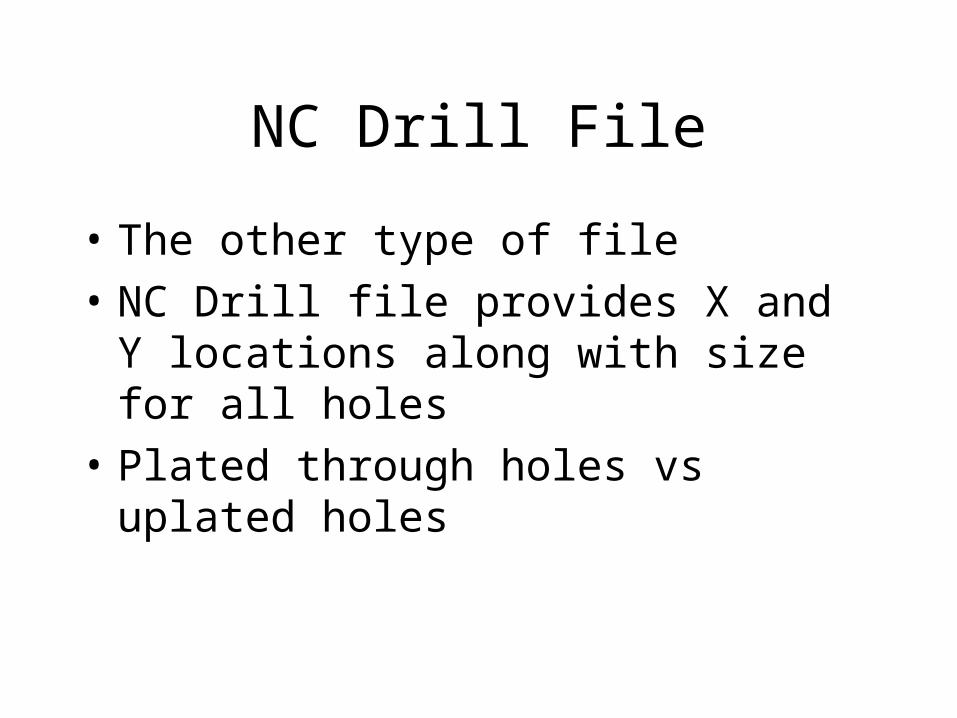
• The other type of file
• NC Drill file provides X and Y locations along with size for all holes
• Plated through holes vs uplated holes
Eagle Extensions
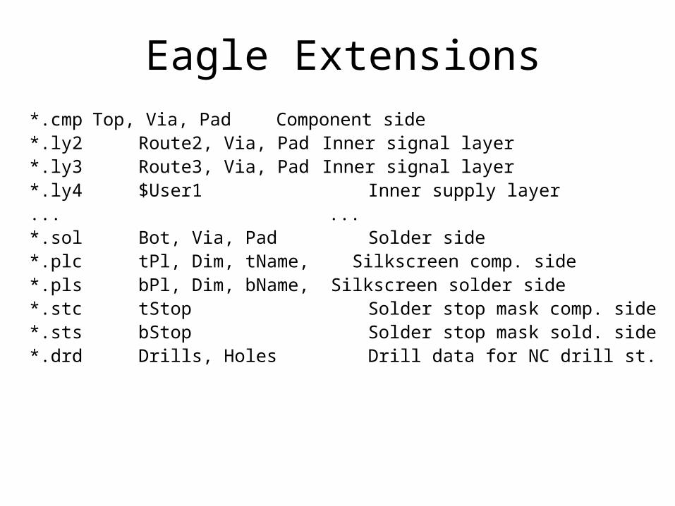
*.cmp Top, Via, Pad Component side*.ly2 Route2, Via, Pad Inner signal layer*.ly3 Route3, Via, Pad Inner signal layer*.ly4 $User1 Inner supply layer... ...*.sol Bot, Via, Pad Solder side*.plc tPl, Dim, tName, Silkscreen comp. side*.pls bPl, Dim, bName, Silkscreen solder side*.stc tStop Solder stop mask comp. side*.sts bStop Solder stop mask sold. side*.drd Drills, Holes Drill data for NC drill st.
Design Process in Practice
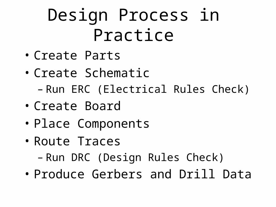
• Create Parts
• Create Schematic– Run ERC (Electrical Rules Check)
• Create Board
• Place Components
• Route Traces– Run DRC (Design Rules Check)
• Produce Gerbers and Drill Data
Design Rules
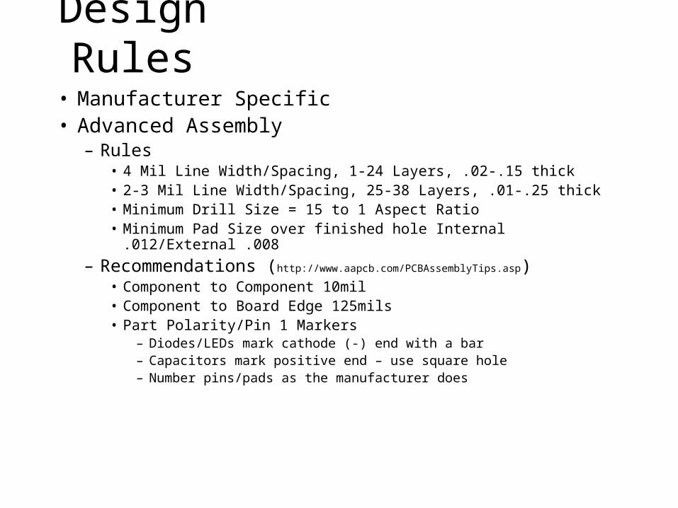
• Manufacturer Specific• Advanced Assembly
– Rules• 4 Mil Line Width/Spacing, 1-24 Layers, .02-.15 thick• 2-3 Mil Line Width/Spacing, 25-38 Layers, .01-.25 thick• Minimum Drill Size = 15 to 1 Aspect Ratio• Minimum Pad Size over finished hole Internal .012/External .008
– Recommendations (http://www.aapcb.com/PCBAssemblyTips.asp)• Component to Component 10mil• Component to Board Edge 125mils• Part Polarity/Pin 1 Markers
– Diodes/LEDs mark cathode (-) end with a bar– Capacitors mark positive end – use square hole– Number pins/pads as the manufacturer does
Ogres, Onions, and Parfaits
• Parts, Schematics, and PCBs are like Ogres– They have layers
• Pretty Much Automatic – but Pay Attention to them
Creating Parts in Eagle
• Parts are created and stored in a library– Difficult to move from one library to another
• Parts consist of– Package: The footprint in the layout– Symbol: The drawing for the schematic– Device: Assigns a symbol to a package
Symbol• Pins
– Visible attribute • Pad – Display pad name from Package• Pin – Displays pin name from Symbol• Both – Displays both pin and pad names
– Direction should match pin’s function• ERC issue
• Outline “Wires” on 94 Symbols layer• Name “>NAME” on 95 Names layer• Value “>VALUE” on 96 Values layer
– Instead of “>VALUE” may use name of device– i.e. TSP78514, Teensy++
Package
• Package name should reflect package type– DIP14, TO220-5, LCC20
• Pads – type ‘1’ including ‘s in text box then place pads - pads will be numbered sequentially
• Pin 1’s pad should be square – or otherwise identified
• Package outline on 21 tPlace layer• Name “>NAME” on 25 tNames layer• Value “>VALUE” on 27 tValues layes
Package cont.
• Critical Dimensions– Hole to hole spacing– Pad to pad spacing in surface mount devices– Package size is non-critical
• Start by placing Pin 1’s pad– Place other pads, holes, and outlines in
reference to Pin 1
Device
• Add a Symbol (Library editor calls this Add a Part) by clicking on two input AND
• Add a Package by clicking on the New button• Connect the Symbol’s Pins to the Package’s Pads
by clicking on the Connect button– Opens a new dialog box
• Click on Pin and Pad to be connected then
• Click on Connect
• Repeat
• Click on Prefix button to assign a prefix– IC, R, C, CONN, J, etc…
Save Library
• Perhaps you shouldn’t have waited until now to save your work
Schematic Entry
• Schematic captures the electrical connections of your design
• Schematic should flow from left to right• Frames make your schematic look
professional• Decoupling Capacitors
– Bulk where power connects to board– At least one per IC
Schematic Entry Design Flow
• Place parts
• Define electrical connections
• Run ERC
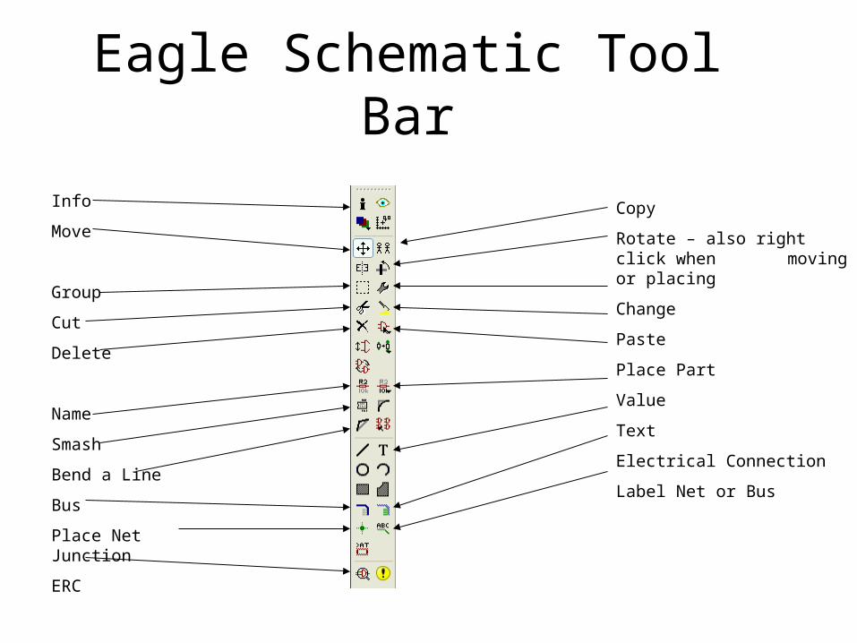
Eagle Schematic Tool Bar
Info
Move
Group
Cut
Delete
Name
Smash
Bend a Line
Bus
Place Net Junction
ERC
Copy
Rotate – also right click when moving or placing
Change
Paste
Place Part
Value
Text
Electrical Connection
Label Net or Bus
PCB Design• Define board outline and other mechanicals
– Mounting holes
• Place parts– Use Air Wires/Ratsnest to help place
• Autoroute• Add finishing touches
– Name of Board– Board Revision– Assembly Revision
• Helpful silkscreen legends• DRC
PCB Design cont.
• Edit/Net classes– Allows different widths and hole sizes for
named nets
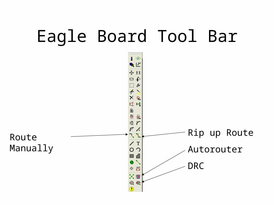
Eagle Board Tool Bar
Route Manually Rip up Route
Autorouter
DRC
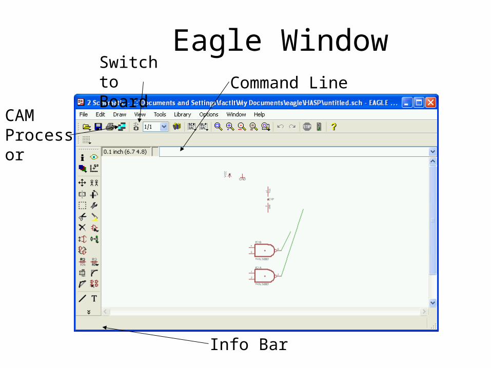
Eagle WindowSwitch to Board Command Line
Info Bar
CAM Processor
Creating Gerbers and Drill File• Create Drill File
– File/Run drillcfg.ulp create .drl file– A list of all drill sizes needed
• Use CAM Processor to Create more Drill files– File/Open/Job – choose excellon.cam– Click on Process Job button– Creates .dri and .drd files
• Use CAM Processor to Create Gerbers– File/Open/Job – choose gerb274x.cam– Check Tabs for proper layer setup– Click on Process Job button– Creates .cmp, .gpi, .plc, .sol, .stc, .sts, .crc, etc…– Might have to add cream component

View Gerbers
• Before submitting your files to a board house view them in a Gerber file viewer– Viewplot www.viewplot.com