principal static wind loads - ulgorbi.ulg.be/bitstream/2268/152897/1/fulllengthpaper.pdf ·...
TRANSCRIPT

Principal Static Wind Loads
N. Blaise1 and V. Denoël1
1Structural Engineering Division, Faculty of Applied Sciences, University of Liège, Liège,Belgium. [email protected]
Abstract
The concept of static wind load is widely used in practice for structural wind design. In thiscontext, this paper assesses the envelope reconstruction problem stated as follows: find the best setof static loadings that is optimum to reproduce by static analyses, the envelope values of structuralresponses resulting from a formal buffeting dynamic analysis. A solution was recently derivedby means of Principal Static Wind Loads which are well-suited for this problem. The concept isillustrated with a large stadium roof and the accuracy of the envelope reconstruction is analysed.
1 Introduction
This paper illustrates a new type of loadings, the Principal Static Wind Loads (PSWLs), recently in-troduced by Blaise & Denoël (2013). These static loadings are well-suited for combinations (Blaiseet al., 2012) and are expected to reproduce by static analyses the envelope values, minimum and max-imum, of internal forces resulting from a dynamic buffeting analysis. This envelope reconstructionproblem (Blaise & Denoël, 2013) has already been tackled using different bases of static wind loadsestablished with (i) Covariance Proper Transformation (CPT) (Katsumura et al., 2007) or (ii) SpectralProper Transformation (Fiore & Monaco, 2009) of the wind pressure field and (iii) Equivalent StaticWind Loads (ESWL) (Zhou et al., 2011). Each of the aforementioned methods considers laboriouscombinations of their static wind loads in order to target all (i) or a selected number of (ii,iii) theenvelope values. Unfortunately, the first two focus on the aerodynamic loading and therefore do notinclude the structural behaviour of the structure.
In this paper, we seek to demonstrate the optimality of the PSWL basis for combinations consid-ering the envelope reconstruction problem. This is illustrated on “Le Grand Stade de Lille Métropole”which is a large stadium roof at Lille, France. The efficiency of the PSWL basis is assessed by com-parison with CPT loading modes and ESWLs.
Figure 1-(a) shows three different parts of the roof: the retractable one and parts above the ambu-latories and above the grandstands. Figure 1-(b) shows the standard deviations of the vertical externalforces on the roof for a wind blowing from East and adequately derived from the aerodynamic pres-sures obtained with wind tunnel measurements on the model of the stadium shown in Fig. 1-(c).
2 Formal buffeting dynamic analysis
The aerodynamic pressures qtot(t) obtained with wind-tunnel measurements, are transformed to nodalexternal forces ftot(t) separated into a mean part µp and a fluctuating part f(t)
ftot = µf + f .
The dynamic motion of the structure x is obtained by solving the equation of motion
1

6th European and African Wind Engineering Conference 2
Figure 1: (a) Three different parts of the roof, (b) standard deviations of the vertical external forceson the roof for a wind blowing from east and (c) model of the stadium in the wind tunnel (courtesy ofCSTB).
Mx + Cx + Kx = f . (1)
The mean part µx and the background contribution x(B)(t) of the nodal displacements are respectivelyobtained as
µx = K−1µf ; x(B) = K−1f .
Because it is more appropriate, the resonant behaviour of the structure is computed by solving Eqn.1in the modal basis
M?η + C?η + K?η = f? η(R) = η −K?−1f?(t)
where M?, C? and K? are the generalized mass, damping, and stiffness matrices respectively, η(t)are the modal coordinates, with η(R)(t) their resonant contribution, f?(t) is the generalized forces andthe dot denotes time derivative.
The total motion of the structure is expressed by
xtot = µx + x(B) + φη(R)
where φ collects the mode shapes. Results of the formal buffeting analysis can be found in (Blaise,2011). Many structural responses —internal forces, reactions, stresses— are obtained by linear com-binations of the nodal displacements
rtot = Oxtot
where O is a matrix of influence coefficients. For the design purpose, minimum rmin and maximumrmax values of structural responses may be computed as
rmin = −gσr ; rmax = gσr (2)
where g is the unique peak factor (taken equal to 3.5 here for simplicity) and σr collects the standarddeviations of the structural responses. Eqn.2 defines the envelope (rmin, rmax) and design of thestructure is based on the design envelope (rd,min, rd,max) obtained by

6th European and African Wind Engineering Conference 3
rd,min = µr + rmin ; rd,max = µr + rmax
where µr = Oµx is the mean part of the structural responses.
3 Envelope reconstruction problem
The problem tackled in this paper is the reconstruction of the envelope (rmin, rmax) obtained with thebuffeting analysis detailed in Section 2 by means of static analyses under an appropriate set of staticloadings Ps which we refer to with symbol s. The envelope that we want to reconstruct is composedof the six internal forces (axial force, two bending moments, two shear forces and torque) for all thebeam elements (2542), giving N r = 30504 structural responses.
Three sets of static loadings are established. They are composed of (i) loading modes obtainedwith covariance proper transformation (CPT) of the pressure field (s ≡ c), (ii) equivalent static windloads (s ≡ e) and (iii) principal static wind loads (s ≡ p).(i) The CPT is applied to the covariance matrix of external forces Cf(
Cf −CcI)Pc = 0 (3)
where Cc is a diagonal covariance matrix of principal components ordered by decreasing variances, Iis the identity matrix and Pc collects the CPT loading modes.(ii) Equivalent static wind loads pe for each structural response that constitutes the envelope are firstcomputed using the method in (Chen & Kareem, 2001) and then collected in a matrix Pe.(iii) The principal static wind load basis Pp is obtained by Singular Value Decomposition (SVD) ofthis matrix Pe
Pe = PpSV′.
With the SVD operation, each PSWL is no longer associated with a specific structural response, butrather aims at a global reconstruction of the set of equivalent static wind loads and, as a corollary, ofthe envelope of structural responses. Also, the PSWLs are well-suited for combinations because theyare orthogonal vectors due to the SVD operation.
Each loading mode psj produces a corresponding static response rsj
rsj = Apsj ; Rs = APs
where A=OK−1 is a matrix of influence coefficients. Each static response is normalized such that rsjis somewhere tangent to the envelope.
The reconstruction of the envelope rsk =(rs,mink , rs,max
k
)after considering k loading modes is
expressed by the recursive equations
rs,mink = min
(rs,min(k−1);− rsi ; r
si ;0)
; rs,maxk = max
(rs,max(k−1) ; −rsi ; r
si ;0). (4)
Notice that with Eqn.(4), 2k load cases are associated with the kth reconstructed envelope. The enve-lope reconstruction accuracy is assessed by computing the relative errors defined as
εk =rmaxk − rmax
rmax=
rmink − rmin
rmin.
where division is performed element by element.
6th European and African Wind Engineering Conference 4
For design purposes, a finite number of representative design load cases has to be selected. Theordering in the available set of loading modes is done based on the maximization of a choosen indicatorof convergence. Such indicator of convergence is defined as the mean error of all structural responses:
Ψk =1
N r
Nr∑l
εlk (5)
where εlk is the relative error on the lth structural response in the reconstructed envelope with k loadingmodes.
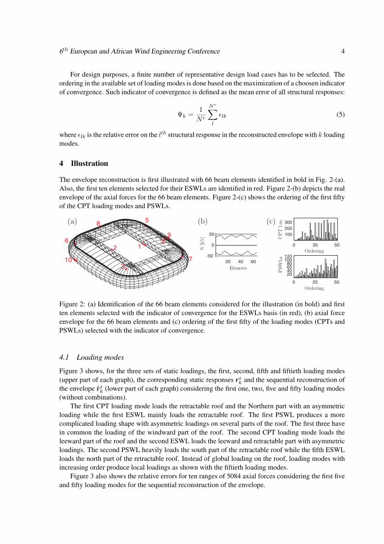
4 Illustration
The envelope reconstruction is first illustrated with 66 beam elements identified in bold in Fig. 2-(a).Also, the first ten elements selected for their ESWLs are identified in red. Figure 2-(b) depicts the realenvelope of the axial forces for the 66 beam elements. Figure 2-(c) shows the ordering of the first fiftyof the CPT loading modes and PSWLs.
Figure 2: (a) Identification of the 66 beam elements considered for the illustration (in bold) and firstten elements selected with the indicator of convergence for the ESWLs basis (in red), (b) axial forceenvelope for the 66 beam elements and (c) ordering of the first fifty of the loading modes (CPTs andPSWLs) selected with the indicator of convergence.
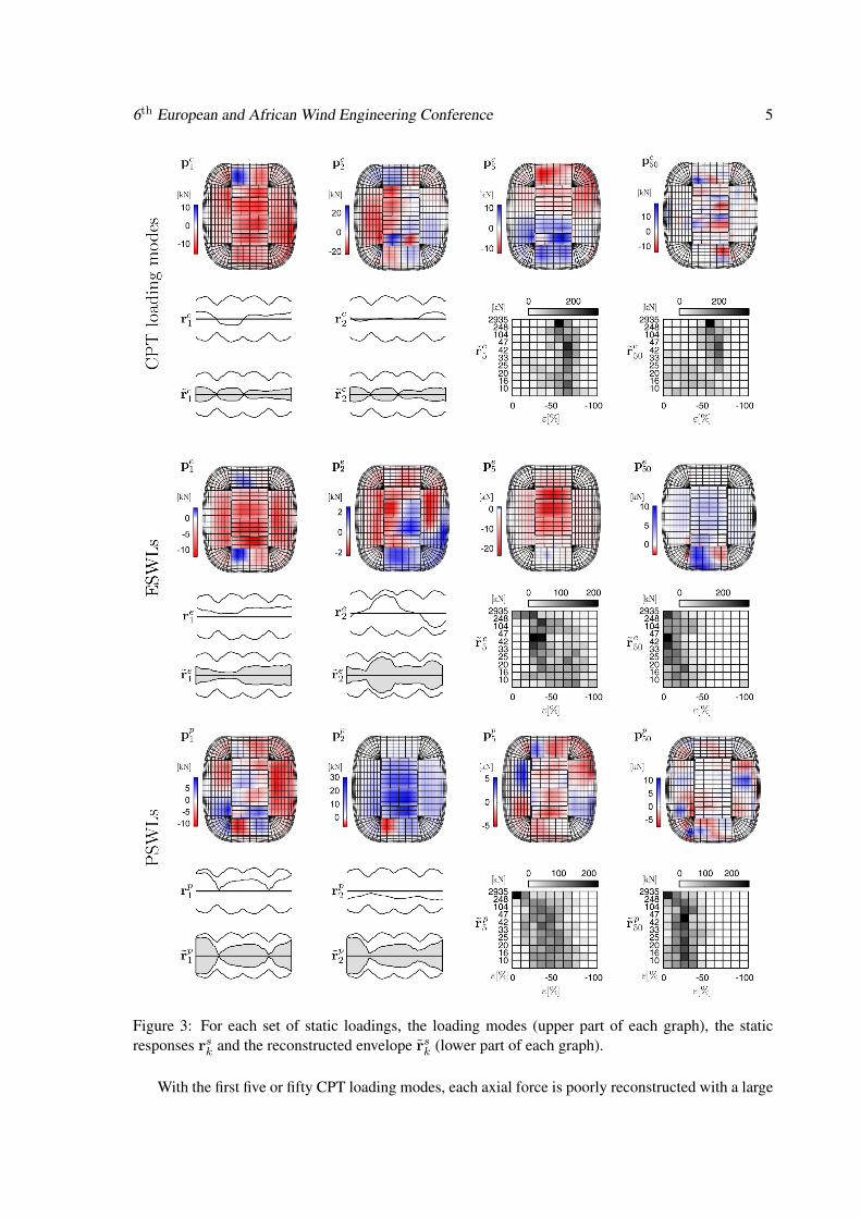
4.1 Loading modes
Figure 3 shows, for the three sets of static loadings, the first, second, fifth and fiftieth loading modes(upper part of each graph), the corresponding static responses rsk and the sequential reconstruction ofthe envelope rsk (lower part of each graph) considering the first one, two, five and fifty loading modes(without combinations).
The first CPT loading mode loads the retractable roof and the Northern part with an asymmetricloading while the first ESWL mainly loads the retractable roof. The first PSWL produces a morecomplicated loading shape with asymmetric loadings on several parts of the roof. The first three havein common the loading of the windward part of the roof. The second CPT loading mode loads theleeward part of the roof and the second ESWL loads the leeward and retractable part with asymmetricloadings. The second PSWL heavily loads the south part of the retractable roof while the fifth ESWLloads the north part of the retractable roof. Instead of global loading on the roof, loading modes withincreasing order produce local loadings as shown with the fiftieth loading modes.
Figure 3 also shows the relative errors for ten ranges of 5084 axial forces considering the first fiveand fifty loading modes for the sequential reconstruction of the envelope.
6th European and African Wind Engineering Conference 5
Figure 3: For each set of static loadings, the loading modes (upper part of each graph), the staticresponses rsk and the reconstructed envelope rsk (lower part of each graph).
With the first five or fifty CPT loading modes, each axial force is poorly reconstructed with a large

6th European and African Wind Engineering Conference 6
part that has a relative error larger than 50% in magnitude.Application of the first five and fifty ESWLs improve significantly the reconstruction and most of
the axial forces have underestimations in [−50%, 0], and [−20%, 0], respectively. Application of thefirst five PSWLs improves significantly the reconstruction, especially for large values of axial forces.The first fifty PSWL produces underestimations larger than [−30%, 0].
Due to the SVD operation, for the CPT loading modes and for the PSWLs, considering moreloadings than fifty does not improve significantly the reconstructed envelope because no combinationis considered. An interesting approach may be to consider combinations of them to ensure a higherrate of envelope reconstruction.
4.2 Combinations
Any arbitrary combination coefficients denoted by qs of the CPT loading modes, ESWLs or PSWLsproduces a new static loading denoted by pcs = Psqs associated with structural responses rcs =Apcs .
The successive static analyses under each combination of the loadings modes, selected using theindicator of convergence, produce a sequential reconstruction of the envelope rcsk =
(rcs,mink , rcs,max
k
).
From a practical view point and with M loading modes, the combination coefficient are obtainedby shooting in a random direction (qs1, q
s2, . . . , q
sM ) generated with a Monte Carlo simulation technique
(10(M−1)2M generations), then by scaling the generated combination in order to restore the tangencycondition with the actual envelope.
The combination coefficients of the first two, three and five loading modes are first generated withMonte-Carlo simulations. With the increase of the number of loadings M , Monte-Carlo simulationmay become heavy to perform, considered combinations are predefined for the first six and ten loadingmodes. These predefined combinations are obtained by considering all possible combinations if eachcombination coefficient can take - 1,1 or 0 values scaled to fulfill the tangency condition. For Mloadings, the subspace of considered combinations counts 3M−1 different couple of coefficients.
Figure 4 allows to appreciate the gain of reconstructed envelope accuracy by combinations of theloading modes. The evolution of Ψ is depicted as a function of the number of design wind loadsderived with an increasing number of loading modes with or without combinations. The first threegraphs from left to right are the results if no combination is considered and each loading mode issequentially applied and if coefficients of Monte-Carlo simulation are used to combine the first twoand three loading modes, respectively. The fourth, fifth and sixth graphs from left to right are theresults if coefficients of Monte-Carlo simulation are used to combine the first five loading modesand if predefined considered combinations are used to combine the first six and ten loading modes,respectively.
Horizontal lines indicate the limit values for Ψ that would be obtained if all coefficients in thedefined subspace of coefficients in the two approaches (coefficients of Monte-Carlo simulation orpredefined considered combinations) were considered.
Figure 4 confirms that the ESWLs or PSWLs performed better than the CPT loading modes whichare not suited for the envelope reconstruction because the behaviour of the structure is not incorpo-rated. Without combinations, the PSWLs perform better than the ESWLs up to the 12 loading mode(24 design wind load) as a consequence of the SVD operation for the PSWLs. Indeed, the SVD oper-ation produces an ordering with the principal coordinates and consideration of more and more PSWLs(or CPT loading modes) does not bring significant improvement of Ψ. With combinations of a reducednumber of loading modes, the key-idea is to reach and even exceed the lower limit of the grey areafixed by the value of Ψ obtained with the first fifty ESWLs applied without combinations.

6th European and African Wind Engineering Conference 7
If combinations are considered, a rapid increase is observed with just the first few design windloads, then followed by a transition zone where the slopes decrease with a slow monotonic conver-gence toward their respective limit values.
With combinations of the first four PSWLs, the grey area is not reached. More loading modes haveto be combined and predefined considered combinations are considered. Considered combinations ofthe first six loading modes shows higher curves than the ones obtained with coefficients of Monte-Carlo simulation of the first four loading modes.
Considered combinations of the first ten PSWLs, allows to reach the grey area with a number ofdesign wind loads divided by two and for 100 design wind loads, Ψ is equal to 12% in magnitude.
Figure 4: (a) Evolution of the indicator of convergence as a function of the subpaces considered for thecoefficients and the number of CPT loading modes, ESWLs and PSWLs. Subpaces for the coefficientsare without combinations, obtained with Monte-Carlo simulations and considered combinations. (b)Reconstructed envelope rcs50 for a basis composed of the first ten loading modes and considering 100design wind loads.
Figure 4-(b) shows, for a basis composed of the first ten loading modes and considering 100 design

6th European and African Wind Engineering Conference 8
wind loads, the error on the reconstructed envelope of the 66 axial forces (upper part of each graph)and the distribution of the relative errors for ten ranges of 5084 axial forces (lower part of each graph)for (from left to right) the CPT loading modes, ESWLs and PSWLs.
5 Conclusion
A new type of wind loading, the principal static wind load, has been recently introduced as an opti-mum basis for the envelope reconstruction problem. Indeed, PSWLs are not associated with specificresponses, contrary to the ESWLs, and include the structural behaviour of the structure, contrary tothe CPT or SPT loading modes. Also combinations of them are not the result of a pseudo-inverseor a least-square optimization of a number of user-defined structural responses. Combinations ofthem aims at the maximization of a user-defined indicator of convergence considering all structuralresponses. Due to the SVD operation, PSWLs are well-suited for combinations and perform betterthan the CPT loadings modes or ESWLs for the envelope reconstruction problem. Moreover, only areduced number of representative load patterns has to be kept.
Acknowledgement
We would like to acknowledge the “Centre Scientifique et Technique du Bâtiment” in Nantes in Franceand also the design office “Greisch” in Liège, in Belgium for having provided the measurements inwind tunnel and the finite element model, respectively.
References
Blaise, N., Denoël V. 2011. Stochastic analysis of a stadium roof from deterministic wind tunnelmeasurements. In: Proceedings of 13th International Conference on Wind Engineering.
Blaise, N., & Denoël, V. 2013. Principal Static Wind Loads. Journal of Wind Engineering andIndustrial Aerodynamics, 113, 29–39.
Blaise, N., Hamra, L., & Denoel, V. 2012. Principal Static Wind Loads on a large roof structure. In:Proceedings of the 12th ANIV conference of wind engineering In Vento. Proceedings of the 12thANIV conference of wind engineering In Vento.
Chen, X. Z., & Kareem, A. 2001. Equivalent static wind loads for buffeting response of bridges.Journal of Structural Engineering-Asce, 127(12), 1467–1475.
Fiore, A., & Monaco, P. 2009. POD-based representation of the alongwind equivalent static force forlong-span bridges. Wind and Structures, An International Journal, 12(3), 239–257.
Katsumura, A., Tamura, Y., & Nakamura, O. 2007. Universal wind load distribution simultaneouslyreproducing largest load effects in all subject members on large-span cantilevered roof. Journal ofWind Engineering and Industrial Aerodynamics, 95(9-11), 1145–1165.
Zhou, X., Gu, M., & Li, G. 2011. Application Research of Constrained Least-Squares Method inComputing Equivalent Static Wind Loads. In: Proceedings of the 13th International Conference onWind Engineering.