prince mohammad bin fahd university - pmu.edu.sa416c6920416c2d4d... · facilities applying saudi...
TRANSCRIPT
Prin c e Moh ammad Bin Fah d Un iversity C o l l e g e o f E n g i n e e r i n g
Department of Mechanical Engineering
Internship Report
At
Saudi Aramco Company
R e p o r t i n g P e r i o d
[14/07/2012 - 25/07/2012]
S u b m i t t e d b y
[ Al i M o h a m m a d Al - M a r r i ]
[ 2 0 0 8 0 0 9 0 5 ]
[ s u b m i s s i o n d a t e ( 2 7 / 0 7 / 2 0 1 2 ) ]
Mechanical Engineering Department
Summer 2012
2012

1
Summary
I got a chance to have my internship with Saudi Aramco Company which is the national oil company
of Saudi Arabia and the largest oil company in the world. Saudi Aramco has both the largest proven
crude oil reserves, at more than 260 billion barrels and largest daily oil production. Saudi Aramco
owns the Ghawar Field, the world's largest oil field, and the Shayba Field, one of the world's largest
oil fields. Ghawar is an oil field located in AL-Hasa ,Saudi Arabia. Measuring 280 by 30 km, it is by
far the largest conventional oil field in the world. Ghawar is entirely owned and operated by Saudi
Aramco, the nationalized Saudi oil company. Relatively little technical information is publicly
available, because the company and Saudi government closely guard field performance data and per-
field production details. Historically, Ghawar has been subdivided into five production areas, from
north to south: 'Ain Dar and Shedgum, 'Uthmaniyah, Hawiyah and Haradh. The major oasis of AL-
Hasa and villages are located on Ghawar's east flank, corresponding to the 'Uthmaniyah production
area. Ghawar was discovered in 1948 and put on stream in 1951. Some sources claim Ghawar peaked
in 2005, though this is strongly contested by the field operators.
Approximately 60-65% of all Saudi oil produced between 1948 and 2000 came from Ghawar.
Cumulative production until April 2010 has exceeded 65 billion barrels . Currently, Ghawar is
estimated to produce over 5 million barrels of oil a day (6.25% of global production).
Ghawar also produces approximately 2 billion cubic feet of natural gas per day.

2
Figure 1: this figure shows all oil and gas fields handled by Saudi Aramco. As notice the largest one is the GHAWAR Field.
3
Background
I have joined one of the company’s departments which is North Ghawar Producing Department
(NGPD). It consists of five divisions; three operations divisions and two maintenance divisions. I start
working on June16, 2012 with Abqaiq Producing Division (ABPD) in Abqaiq Gas Oil Separation
Plant# 5 (ABGOSP-5) as assistant to Operations Engineer who is assigned to be my Mentor. His
name is Mohammed A, Al-Hadrami. Mohammed got his bachelor degree “Chemical Engineering”
from KFUPM and he joined Saudi Aramco in 2008. He worked with Safaniyah Offshore Producing
Department (2008-2009) as Plant Engineer. Then, he joined Northern Area Technical Support
Department (2009-2010) as a Design Engineer. After that, Mohammed moved to North Ghawar
Producing Department with Engineering Division. Now, he is handling two facilities (GOSPs) plus
Oil Field as an Operations Engineer. Moreover, he is responsible for new hired engineers’
orientations. Mohammed contact mean as follows,
Mail PO Box 45, Abqaiq 31311, Kingdom of Saudi Arabia Mobile +966 55 1158 10
Email [email protected]
As planned, the third two weeks, from July 14 until July 25, 2012, I joined North Ghawar Engineering
Division. This division is under NGPD (North Ghawar Producing Department) and has 4 engineering
units: Plant Engineering (PEU), Technical Support (TSU), Project Coordination (PCU) and Inspection
& Corrosion (ICU). I was assigned with Inspection since it is in charge of inspecting all NGPD
facilities applying Saudi Aramco standards. This unit has three groups (Mechanical, Support,
Corrosion).
In this report I will explain the three groups activities with the inspection procedure and how they are
implementing Aramco standards on their duties.
4
Progress
Mechanical Inspection:
This group is focusing on three fields; Plant equipments, welding and coating.
A) Plant equipments are the most important portion in the GOSP, so to get efficient operating
equipment you need to implement a high-quality inspection standard before using it. Following are
some of the equipments Valves, Pipes, and Drums.
In this report I will concentrate on those equipments that I have observed their inspection.
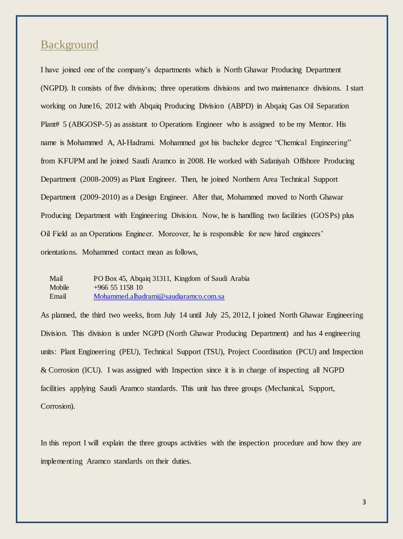
Pipes:
Figure 1: Pipes
1. Verify the piping layout as installed conforms to the drawings.
2. Verify the weld preparations conform to WPS.
3. Verify the qualifications of all welders (coaters, blasters, other as necessary) on the installation.
4. Verify pre-installation pressure testing of the equipment.
5. Verify the welding consumables ate of the proper type and properly stored.
6. Inspect the internal and external coating.
7. Check for damaged materials and equipment.
8. Verify the preheat treatment of the welds
9. Inspect piping support.
10. Inspect trenching of backfill of ditch, if applicable.
11. Verify post heat treatment of the welds.
5
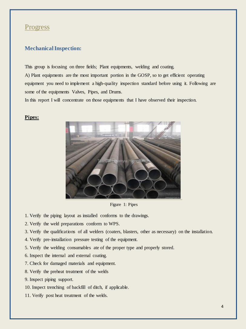
Valves:
Figure 2: Valve
1. Locate the specific valve on the P&ID.
2. Identify the valve make and type.
3. Obtain a drawing of the valve.
4. Determine the pressure rating which will be on the valve body as part of the casting.
5. Measure the valve for nominal bore size and flange size.
6. Inspect the valve for corrosion/erosion.
7. Witness the body and seat hydro-test, if hydro-test is required.
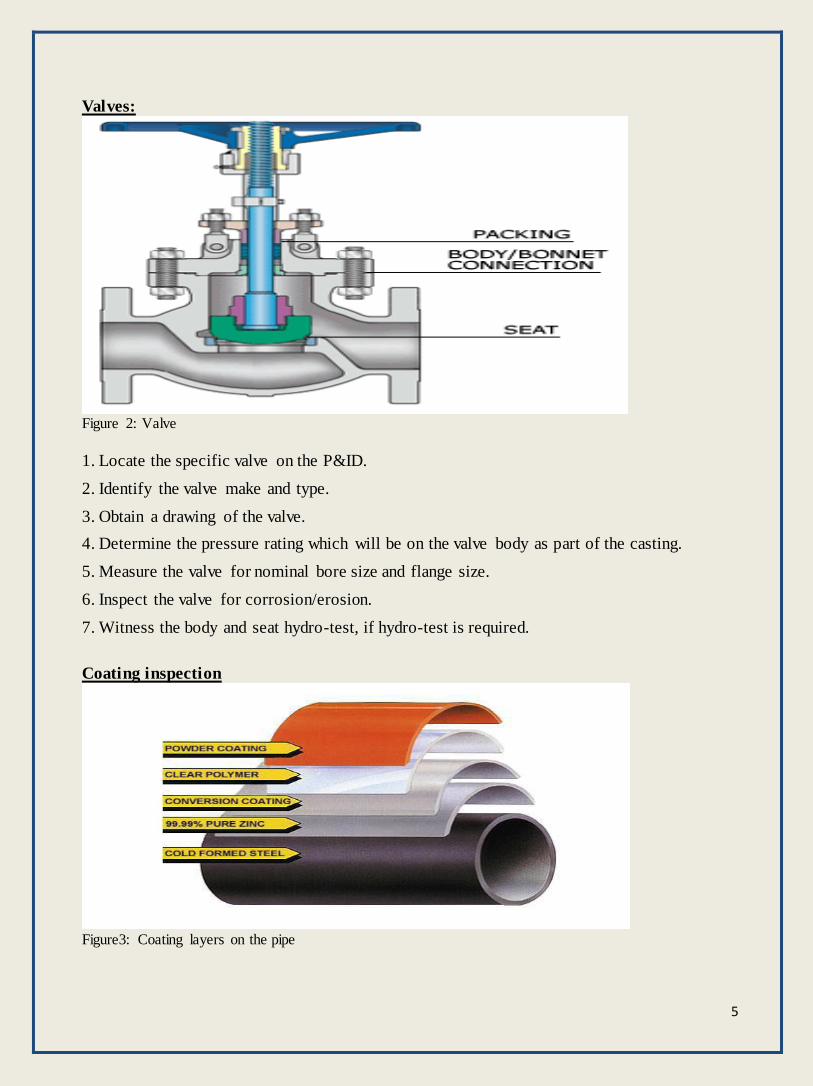
Coating inspection
Figure3: Coating layers on the pipe
6
Coating is the layer that is applied to a pipe or valve to protect it from corrosion, different types of
coating are used on external and internal surfaces.
The inspector role is to check the application of coating e.g. inspect the surface preparation before
coating, verify the optimal thickness for the coating, verify the proper abrasives and checking the
coating preparation.
- Nondestructive evaluation techniques (NDE)
- Radiography
Radiography is one of the most widely used NDE techniques. Radiation is directed through the
material of interest, and a photographic image is recorded on film.
Radiography can be useful in locating failures and it presents no problems in the subsequent failure
analysis.
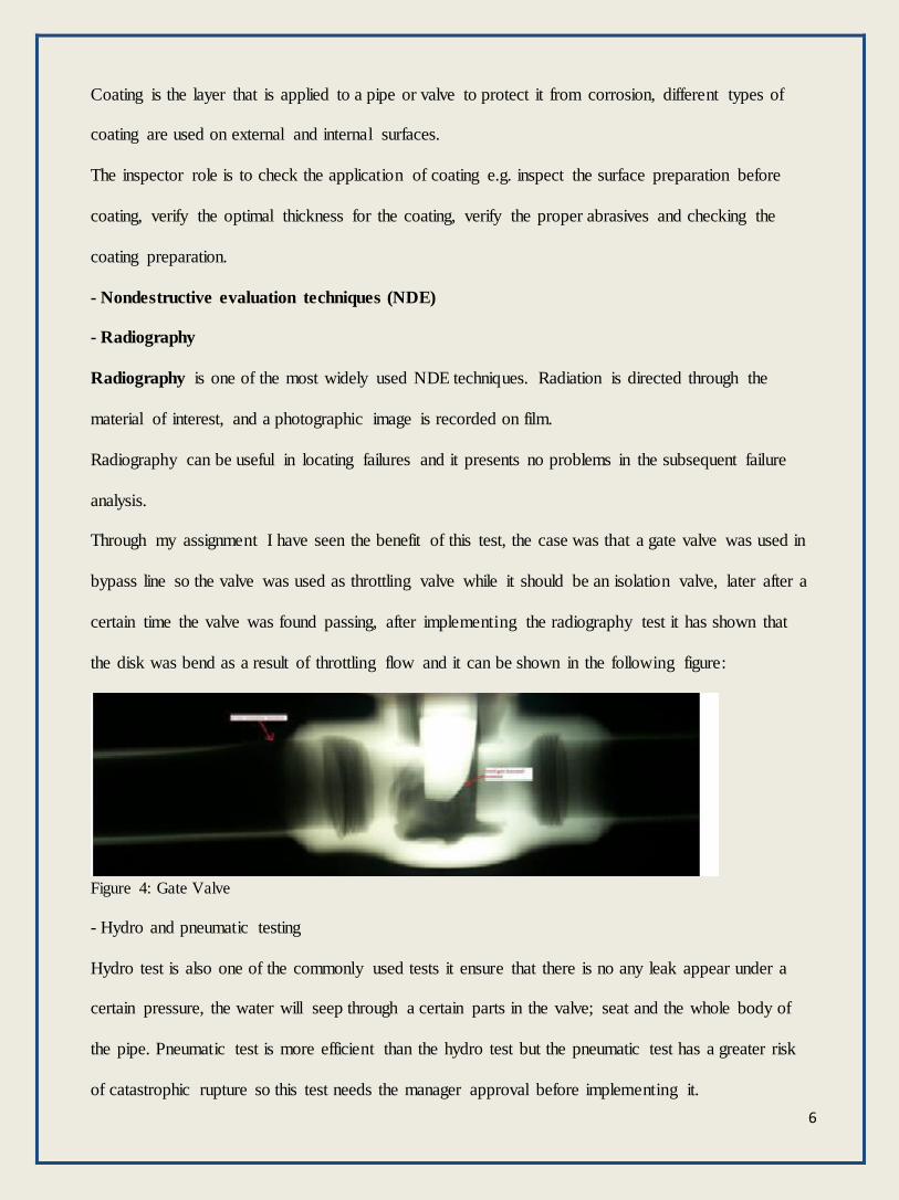
Through my assignment I have seen the benefit of this test, the case was that a gate valve was used in
bypass line so the valve was used as throttling valve while it should be an isolation valve, later after a
certain time the valve was found passing, after implementing the radiography test it has shown that
the disk was bend as a result of throttling flow and it can be shown in the following figure:
Figure 4: Gate Valve
- Hydro and pneumatic testing
Hydro test is also one of the commonly used tests it ensure that there is no any leak appear under a
certain pressure, the water will seep through a certain parts in the valve; seat and the whole body of
the pipe. Pneumatic test is more efficient than the hydro test but the pneumatic test has a greater risk
of catastrophic rupture so this test needs the manager approval before implementing it.

7
- Magnetic particle testing
Magnetic particle testing can be used to detect defects at or near a surface of ferromagnetic materials
and its most effective when it’s used to detect small cracks on two steps in the technique are as
follows:
1- Magnetization of the test piece by means of alternating current for surface defects or direct
current for subsurface defects.
2- Application of finely divided magnetic particles in either a dry powder or suspended in a
liquid. The magnetic particles, in forming visible indications, are attracted to the leakage flux
that is created by the magnetic field.
- Ultrasonic testing
Figure 5: Principles of Ultrasonic Testing
The ultrasonic inspection technique uses low energy and high frequency sound waves to measure wall
thickness and to detect defects in materials. Sound waves are beamed into the test material and
reflected from surfaces or discontinuities.
Based on the time for return of the echoes, metal thickness can be determined or defects located,
usually by calibration with reference standards.
Advantages Disadvantages
High Penetrating power Manual operation require careful attention by experience technicians
High sensitivity Extensive technical knowledge is required for
the development of inspection procedure.
No Effects on Equipment and materials Possible interference problems with foreign
structures resistivity
Capable of portable or highly automated
operation
Surface must be prepared by cleaning and
removing loose scale, paint, etc
Table1: Advantages and disadvantages of UT test
8
Through the assignment I have done the ultrasonic test on a pipe and it was easy to operate and it
gives you the thickness in a short time.
- Liquid penetrate testing
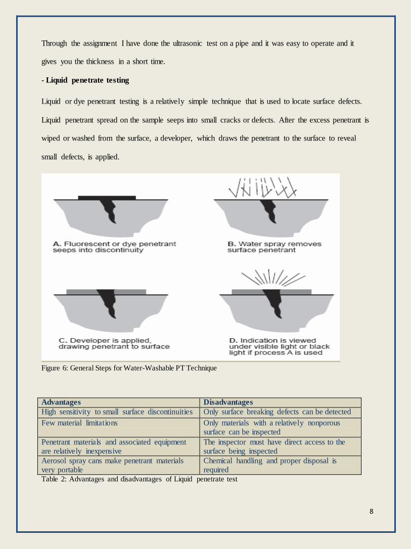
Liquid or dye penetrant testing is a relatively simple technique that is used to locate surface defects.
Liquid penetrant spread on the sample seeps into small cracks or defects. After the excess penetrant is
wiped or washed from the surface, a developer, which draws the penetrant to the surface to reveal
small defects, is applied.
Figure 6: General Steps for Water-Washable PT Technique
Advantages Disadvantages
High sensitivity to small surface discontinuities Only surface breaking defects can be detected
Few material limitations Only materials with a relatively nonporous surface can be inspected
Penetrant materials and associated equipment are relatively inexpensive
The inspector must have direct access to the surface being inspected
Aerosol spray cans make penetrant materials very portable
Chemical handling and proper disposal is required
Table 2: Advantages and disadvantages of Liquid penetrate test

9
Support Inspection:
The support inspection can be classified into two groups: Civil and Electric inspection.
Civil inspection:
In this part I will go through the major civil inspection jobs:
A) Excavation:
Figure 7: Excavation job
1- Verify location of excavation is correct.
2- Locate vertical and horizontal control references points(if applicable)
3- Verify excavation work meets safety guidelines: slide sloping, shoring, method of (entry, exit,
safety boundary, markets)
4- Verify work in progress: soil type, soil conditions, elevation control, water table and horizontal
control.
B) Filling:
To inspect the filling you should first verify if the preparation of the site is meeting the requirements
then check if the fill meet the requirements e.g. type, gradation, maximum dry density or relative
density test results.
10
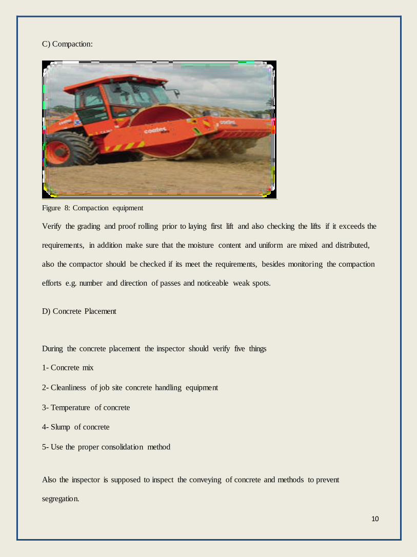
C) Compaction:
Figure 8: Compaction equipment
Verify the grading and proof rolling prior to laying first lift and also checking the lifts if it exceeds the
requirements, in addition make sure that the moisture content and uniform are mixed and distributed,
also the compactor should be checked if its meet the requirements, besides monitoring the compaction
efforts e.g. number and direction of passes and noticeable weak spots.
D) Concrete Placement
During the concrete placement the inspector should verify five things
1- Concrete mix
2- Cleanliness of job site concrete handling equipment
3- Temperature of concrete
4- Slump of concrete
5- Use the proper consolidation method
Also the inspector is supposed to inspect the conveying of concrete and methods to prevent
segregation.
11
Electrical inspection: With the electrical inspection the inspector should stick with the inspection steps in sequence to get
the inspection done safely. In the report I will choose the procedure of the two major equipments
inspection:
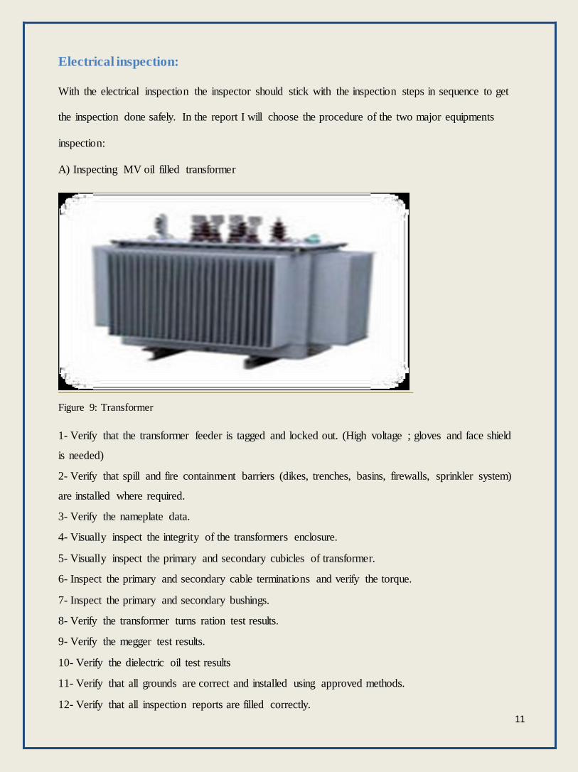
A) Inspecting MV oil filled transformer
Figure 9: Transformer
1- Verify that the transformer feeder is tagged and locked out. (High voltage ; gloves and face shield
is needed)
2- Verify that spill and fire containment barriers (dikes, trenches, basins, firewalls, sprinkler system)
are installed where required.
3- Verify the nameplate data.
4- Visually inspect the integrity of the transformers enclosure.
5- Visually inspect the primary and secondary cubicles of transformer.
6- Inspect the primary and secondary cable terminations and verify the torque.
7- Inspect the primary and secondary bushings.
8- Verify the transformer turns ration test results.
9- Verify the megger test results.
10- Verify the dielectric oil test results
11- Verify that all grounds are correct and installed using approved methods.
12- Verify that all inspection reports are filled correctly.
12
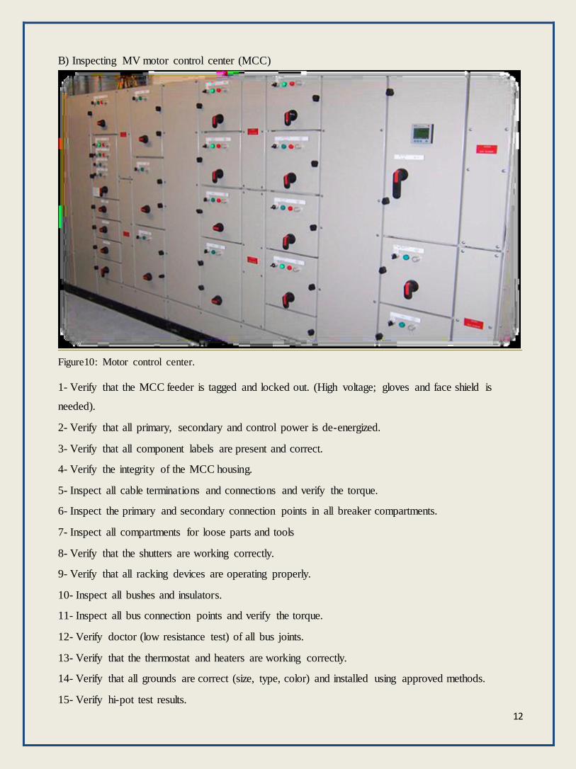
B) Inspecting MV motor control center (MCC)
Figure10: Motor control center.
1- Verify that the MCC feeder is tagged and locked out. (High voltage; gloves and face shield is
needed).
2- Verify that all primary, secondary and control power is de-energized.
3- Verify that all component labels are present and correct.
4- Verify the integrity of the MCC housing.
5- Inspect all cable terminations and connections and verify the torque.
6- Inspect the primary and secondary connection points in all breaker compartments.
7- Inspect all compartments for loose parts and tools
8- Verify that the shutters are working correctly.
9- Verify that all racking devices are operating properly.
10- Inspect all bushes and insulators.
11- Inspect all bus connection points and verify the torque.
12- Verify doctor (low resistance test) of all bus joints.
13- Verify that the thermostat and heaters are working correctly.
14- Verify that all grounds are correct (size, type, color) and installed using approved methods.
15- Verify hi-pot test results.

13
Corrosion Inspection: This group can be organized into two teams Cathadoic protection (cp) and corrosion team.
- Cathadoic protection
There are two types of Cathadoic protection:
A) Galvanic protection
Figure 11: Galvanic anodes in a Vessel
Galvanic anode system is applied when the current requirement is low and it uses sacrificial anodes to
generate the required current, the galvanic system usually used in vessels (Zink), water tanks
(Aluminum), and pipes under road and camel crossings (Magnesium).
Advantages Disadvantages
External power source is not required Driving voltage is limited
Installation costs are low Current output is limited
Maintenance cost are low Effective only in low soil resistivity
Table 3: Advantages and disadvantages of Galvanic Protection
B) Impressed current system
Figure 12: Impressed current system
14
This system is required when high current is needed, it uses rectifier to produce the essential current,
and it’s used on well casing and buried pipelines.
It can be installed horizontal or vertical depending on the conductivity of the soil.
Coke grease is added to the system to increase the flow of the current.
Advantages Disadvantages
High driving voltages High equipment and installation costs
High current outputs High maintenance costs
Adjustable current output low Possible interference problems with
foreign structures resistivity
Table 4: Advantages and disadvantages of impressed current system
- Corrosion group
The main objective of this group is to evaluate the failure cases which occurred, and give
recommendation based on their evaluation. They can evaluate by analyzing the data which they
obtained from the monitoring systems and coupons. Also this group is responsible of the type of
coatings and the material selection.
Through the assignment I have learned that most of the corrosion cases were due to old piping design.
The pipes were designed based on the previous flow rates, so this proves that the velocity of the flow
is an important factor in corrosion occurrences.
That is why the new technologies are required to reduce the corrosion, since the idea of changing the
design to the current flow will cost a lot.
Following is the group techniques to reduce the corrosion:
• Chemical inhibitor
Corrosion inhibitor is injected in three locations; production header, before entering the gas fin fan
and wash water. It’s injected to be mixed with water to form a layer on the pipe to protect it from
corrosion, the corrosion engineer is responsible to calculate and give the exact dosage rate to the
operation. In the oil side the inhibitor rate is depending on the water cut while in the gas side it’s
depending on the flow rate.
15
• Squeezing wells
Corrosion and scale inhibitor are injected to the oil well by a pump and the well should shut in for 48
hours to allow the inhibitor to precipitate on the formation.
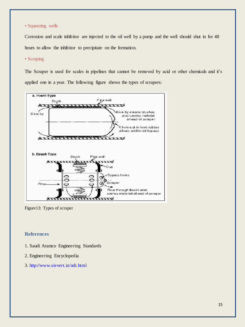
• Scraping
The Scraper is used for scales in pipelines that cannot be removed by acid or other chemicals and it’s
applied one in a year. The following figure shows the types of scrapers:
Figure13: Types of scraper
References
1. Saudi Aramco Engineering Standards
2. Engineering Encyclopedia
3. http://www.sievert.in/ndt.html

16
Plans In this report I have explained the different fields of inspection unit and their major activities.
One of the best things that I have learned in this assignment was being familiar with the Saudi
Aramco Engineering Standards and Engineering encyclopedia, and I have used them in my existing
report.
The most interesting thing in the assignment was that how they are implementing the engineering
standards on their daily activities, and if there was any issue will conflict the standards it will be
rejected even if it’s urgent, this indicates how Saudi Aramco pay attention to the safety factor.
During the assignment I have been introduced to I-plant, and I have familiarized myself with it and
used it to search for pipes drawings.
The next assignment will be with Production Engineering Division as advised by Mentor.

17