primergy bx920 s1 server blade - service...
TRANSCRIPT
PRIMERGY BX920 S1Server-Blade Service Supplement
Edition April 2010

Comments… Suggestions… Corrections…The User Documentation Department would like toknow your opinion of this manual. Your feedback helpsus optimize our documentation to suit your individual needs.
Feel free to send us your comments by e-mail to [email protected].
Certified documentation according to DIN EN ISO 9001:2000To ensure a consistently high quality standard anduser-friendliness, this documentation was created tomeet the regulations of a quality management system which complies with the requirements of the standardDIN EN ISO 9001:2000.
cognitas. Gesellschaft für Technik-Dokumentation mbHwww.cognitas.de
Copyright and Trademarks
© c
ogni
tas.
Ges
ells
chft
für
Tech
nik
-Do
kum
ent
atio
n m
bH
20
10
Pfa
d: C
:\D
oku
me
nte
und
Ein
ste
llung
en\w
alte
r\E
igen
e D
atei
en\b
x920
s1\S
erv
ice
-Sup
plem
ent\
InA
rbe
it\B
X92
0_su
ppl.e
n\B
X9
20_
supp
l_en
.vo
r
Copyright © 2010 Fujitsu Technology Solutions GmbH.
All rights reserved.Delivery subject to availability; right of technical modifications reserved.
All hardware and software names used are trademarks of their respective manufacturers.

BX920 S1 Service Supplement
Contents
1 Preface . . . . . . . . . . . . . . . . . . . . . . . . . . . . . . 5
1.1 Documentation Overview . . . . . . . . . . . . . . . . . . . . 5
1.2 Notational conventions . . . . . . . . . . . . . . . . . . . . . 7
2 Procedure . . . . . . . . . . . . . . . . . . . . . . . . . . . . . 9
3 Important Notes . . . . . . . . . . . . . . . . . . . . . . . . 11
3.1 Notes on Safety . . . . . . . . . . . . . . . . . . . . . . . . . 11
3.2 Environmental protection . . . . . . . . . . . . . . . . . . . 15
4 Replacement routines . . . . . . . . . . . . . . . . . . . . . 17
4.1 Preparation . . . . . . . . . . . . . . . . . . . . . . . . . . . 17
4.2 Replacing processors . . . . . . . . . . . . . . . . . . . . . 20
4.3 Replacing the SAS backplane . . . . . . . . . . . . . . . . . 27
4.4 Installing a mezzanine card . . . . . . . . . . . . . . . . . . 294.4.1 Population rules for mezzanine cards . . . . . . . . . . . . . . 30
4.5 Installing/removing a TPM . . . . . . . . . . . . . . . . . . . 404.5.1 Installing a TPM . . . . . . . . . . . . . . . . . . . . . . . . . 404.5.2 Removing a TPM . . . . . . . . . . . . . . . . . . . . . . . . 42
5 Diagnosis and maintenance . . . . . . . . . . . . . . . . . . 45
5.1 Recovering the Server Blade BIOS . . . . . . . . . . . . . . 45
Index . . . . . . . . . . . . . . . . . . . . . . . . . . . . . . . . . . . . 49

© c
ogn
itas.
Ges
ells
chft
für
Tech
nik-
Dok
um
enta
tion
mbH
200
9 P
fad
: C:\D
oku
men
te u
nd E
inst
ellu
nge
n\w
alte
r\E
igen
e D
atei
en\
bx92
0s1\
Ser
vice
-Su
pple
men
t\InA
rbei
t\B
X9
20_s
upp
l.en\
BX
920
_sup
pl_e
n.iv
z
BX920 S1 Service Supplement 5
1 PrefaceThe PRIMERGY BX920 S1 Scalable Server Blade is an Intel-based server blade, that can be operated in the PRIMERGY BX900 basic unit.
1.1 Documentation Overview
Concept and target groups
This Service Supplement supplements the information contained in the Operating Manual, in the Options Guide and in the Technical Manual.
V ATTENTION!
The activities described in this manual may only be performed by specialist personnel with technical training.
I The installation and removal of the hot-plug components is described in the Operating Manual supplied with the server blade.
Service DVD
A service DVD is available for service partners of Fujitsu Technology Solutions. This DVD contains the following manuals in PDF format:– the “Safety notes and other important information” manual– the Operating Manual for PRIMERGY BX920 S1– the Options Guide for PRIMERGY BX920 S1– the Technical Manual for the system board D2860

6 Service Supplement BX920 S1
Documentation Overview Preface
© c
ogn
itas.
Ge
sells
chft
für
Tech
nik
-Do
kum
enta
tion
mbH
200
9
Pfa
d: C
:\D
oku
men
te u
nd E
inst
ellu
nge
n\w
alte
r\E
ige
ne D
atei
en\
bx92
0s1\
Ser
vice
-Su
pple
men
t\InA
rbei
t\BX
920
_su
ppl.e
n\B
X9
20_s
upp
l_e
n.k0
1
Information/Activity Manual
Features and technical data of the server blade Operating Manual
Installation and initial operation, such as:
– Operation and Display units– Configuring the server blades– Installing the server blades in the basic unit
BIOS setup
Troubleshooting
Installing/removing hot-plug components:
– Hard disk modules
Extensions and conversions
– Installing memory modules– Adding processors
Options Guide
Replacement routines
– Exchanging the processor– Exchanging SAS Backplane– Installing Mezzanine Card – Exchanging TPM
Diagnostics
– BIOS recovery
Service Supplement
Information about the server blade
– Features of the server blades– Board layout– Jumper settings– LED displays– Replacing the battery
Technical Manual
Spare parts Illustrated Spares Catalogue
Detailed safety notes Safety notes
Table 1: Overview of the documentation BX920 S1 Server Blade

BX920 S1 Service Supplement 7
Preface Notational conventions
1.2 Notational conventions
The following notational conventions are used in this manual:
Text in italics indicates commands, menu items or software programs.
“Quotation marks“ indicate names of chapters and terms that are being emphasized.
Ê describes activities that must be performed in the order shown.
V CAUTION! pay particular attention to texts marked with this symbol. Failure to observe this warning may endanger your life, destroy the system or lead to the loss of data.
I indicates additional information, notes and tips.
Table 2: Notational conventions

© c
ogn
itas.
Ge
sells
chft
für
Tech
nik
-Do
kum
enta
tion
mbH
200
9
Pfa
d: C
:\D
oku
men
te u
nd E
inst
ellu
nge
n\w
alte
r\E
ige
ne D
atei
en\
bx92
0s1\
Ser
vice
-Su
pple
men
t\InA
rbei
t\BX
920
_su
ppl.e
n\B
X9
20_s
upp
l_e
n.k0
1

BX920 S1 Service Supplement 9
2 ProcedureV ATTENTION!
The activities described in this manual should only be performed by engineers, service personnel or technical specialists.
Ê First of all please familiarize yourself with the safety instructions in the chapter “Important Notes” on page 11 ff.
Ê Make sure that all the manuals you need (see service DVD) are available, printing out the PDF files if necessary. You will definitely need the operating manuals of the server blade and of your BX900 basic unit.
Ê Shut down the server blade correctly, switch it off and remove it from the basic unit as described in the chapter “Replacement routines” on page 17 ff.
Ê Replace the defective component as described in the relevant chapter.
Ê Close the server blade.
Ê Start the server blade.1
Ê If necessary, configure the operating system as required.1
1 See Operating Manual.

© c
ogn
itas.
Ge
sells
chft
für
Tech
nik
-Do
kum
enta
tion
mbH
200
9
Pfa
d: C
:\D
oku
men
te u
nd E
inst
ellu
nge
n\w
alte
r\E
ige
ne D
atei
en\
bx92
0s1\
Ser
vice
-Su
pple
men
t\InA
rbei
t\BX
920
_su
ppl.e
n\B
X9
20_s
upp
l_e
n.k0
2

BX920 S1 Service Supplement 11
3 Important NotesThis chapter provides safety instructions which you must observe when handling your system.
3.1 Notes on Safety
I The following safety instructions can also be found in the manual entitled “Safety”.
This device complies with the relevant safety regulations for IT equipment, including electronic office machines for use in an office environment.
If you have any questions, contact your sales outlet or the Fujitsu Technology Solutions customer service center.
V ATTENTION!
The activities described in this manual should only be performed by engineers, service personnel or technical specialists. Equipment repairs should only be performed by qualified staff! Any failure to observe the guidelines in this manual could endanger the user (through electric shock, fire hazards) or damage the equipment. Please note that any unauthorized opening of the device will result in the invalidation of the warranty and exclusion from all liability.
Before setting up
V ATTENTION!
● During installation and before operating the device, observe the instructions on environmental conditions for your device (see Operating Manual).
● If the device is brought in from a cold environment, condensation may form both inside and on the outside of the machine.
Before operating the device, wait until it is absolutely dry and has reached approximately the same temperature as the installation site. Any failure to observe the guidelines in this manual could damage the equipment.
12 Service Supplement BX920 S1
Notes on Safety Important Notes
© c
ogn
itas.
Ge
sells
chft
für
Tech
nik
-Do
kum
enta
tion
mbH
200
9
Pfa
d: C
:\D
oku
men
te u
nd E
inst
ellu
nge
n\w
alte
r\E
ige
ne D
atei
en\
bx92
0s1\
Ser
vice
-Su
pple
men
t\InA
rbei
t\BX
920
_su
ppl.e
n\B
X9
20_s
upp
l_e
n.k0
3
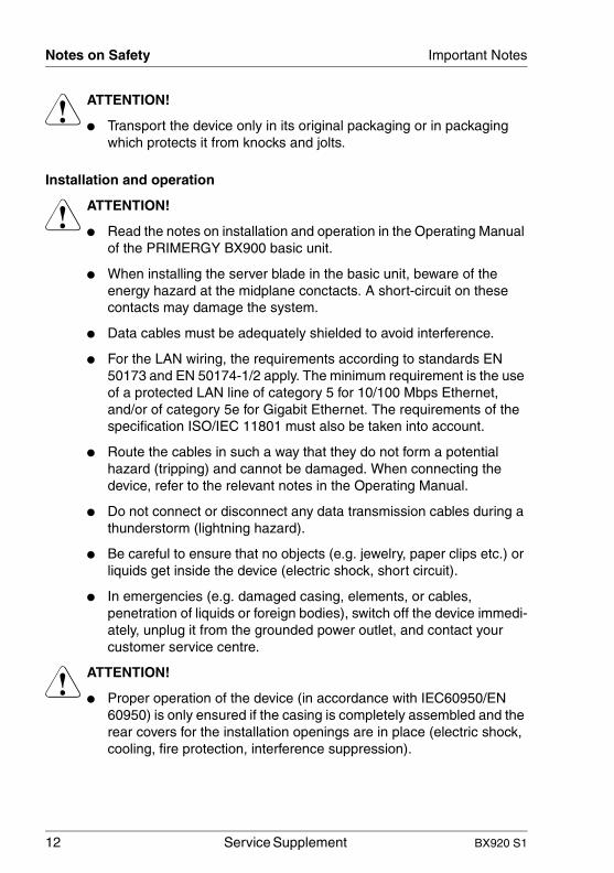
V ATTENTION!
● Transport the device only in its original packaging or in packaging which protects it from knocks and jolts.
Installation and operation
V ATTENTION!
● Read the notes on installation and operation in the Operating Manual of the PRIMERGY BX900 basic unit.
● When installing the server blade in the basic unit, beware of the energy hazard at the midplane conctacts. A short-circuit on these contacts may damage the system.
● Data cables must be adequately shielded to avoid interference.
● For the LAN wiring, the requirements according to standards EN 50173 and EN 50174-1/2 apply. The minimum requirement is the use of a protected LAN line of category 5 for 10/100 Mbps Ethernet, and/or of category 5e for Gigabit Ethernet. The requirements of the specification ISO/IEC 11801 must also be taken into account.
● Route the cables in such a way that they do not form a potential hazard (tripping) and cannot be damaged. When connecting the device, refer to the relevant notes in the Operating Manual.
● Do not connect or disconnect any data transmission cables during a thunderstorm (lightning hazard).
● Be careful to ensure that no objects (e.g. jewelry, paper clips etc.) or liquids get inside the device (electric shock, short circuit).
● In emergencies (e.g. damaged casing, elements, or cables, penetration of liquids or foreign bodies), switch off the device immedi-ately, unplug it from the grounded power outlet, and contact your customer service centre.
V ATTENTION!
● Proper operation of the device (in accordance with IEC60950/EN 60950) is only ensured if the casing is completely assembled and the rear covers for the installation openings are in place (electric shock, cooling, fire protection, interference suppression).

BX920 S1 Service Supplement 13
Important Notes Notes on Safety
● Install only system extensions that satisfy the requirements and rules governing safety, electromagnetic compatibility, and telecommunica-tions terminal equipment.
If you install other extensions, you may damage the system or violate these safety regulations.
Information on which system extensions are suitable can be obtained from the customer service center or your sales outlet.
● The components marked with a warning label (e.g. lightning symbol) may only be opened, removed, or exchanged by authorized, qualified personnel, with the exception of the hot-plug/hot-swap components.
● If you cause a defect on the device by installing or exchanging system extensions, the warranty will be invalidated.
● You may only set the resolutions and refresh rates specified in the operating manual for your monitor. Otherwise, you may damage the monitor. If you are in any doubt, contact your sales outlet or customer service center.
Batteries
V ATTENTION!
● Incorrect replacement of batteries can lead to risk of explosion. The batteries must be replaced with an identical battery or with a battery type recommended by the manufacturer. see “Technical Manual System Board D2860 for BX920“.
● Do not throw batteries into the trash can. Please dispose of them in accordance with local regulations for special refuse.
V ATTENTION!
● Replace the lithium battery on the system board in accordance with the instructions in the Technical Manual for the system board.
● All batteries containing pollutants are marked with a symbol (a crossed-out garbage can). In addition, the marking is provided with the chemical symbol of the heavy metal decisive for the classification as a pollutant:
Cd CadmiumHg MercuryPb Lead

14 Service Supplement BX920 S1
Notes on Safety Important Notes
© c
ogn
itas.
Ge
sells
chft
für
Tech
nik
-Do
kum
enta
tion
mbH
200
9
Pfa
d: C
:\D
oku
men
te u
nd E
inst
ellu
nge
n\w
alte
r\E
ige
ne D
atei
en\
bx92
0s1\
Ser
vice
-Su
pple
men
t\InA
rbei
t\BX
920
_su
ppl.e
n\B
X9
20_s
upp
l_e
n.k0
3
Modules with electrostatic-sensitive components:
Components that might be damaged by electrostatic discharge (ESD) are marked with the following label:
Figure 1: ESD labe
When you handle components fitted with ESDs, you must observe the following points under all circumstances:
● Remove the power plug from the power socket before inserting or removing components containing ESDs.
● You must always discharge yourself of static charges (e.g. by touching a grounded object) before working.
● The equipment and tools you use must be free of static charges.
● Only touch the components at the positions highlighted in green (Touch-points).
● Do not touch any exposed pins or conductors on a component.
● Use a grounding cable designed for this purpose to connect yourself to the system unit as you install components.
● Place all components on a static-safe base.
I You will find a detailed description for handling ESD components in the relevant European or international standards (DIN EN 61340-5-1, ANSI/ESD S20.20).

BX920 S1 Service Supplement 15
Important Notes Environmental protection
3.2 Environmental protection
Environmentally-friendly product design and development
This product has been designed in accordance with the Fujitsu Siemens Computers standard for “environmentally friendly product design and devel-opment”. This means that key factors such as durability, selection and labeling of materials, emissions, packaging, ease of dismantling and recycling have been taken into account.
This saves resources and thus reduces the harm done to the environment.
Energy-saving information
Devices that do not need to be constantly switched on should be switched off until they are needed as well as during long breaks and after completion of work.
Packaging information
Do not throw away the packaging. You may need it later for transporting the system. If possible, the equipment should only be transported in its original packaging.
Information on handling consumables
Please dispose of printer consumables and batteries in accordance with the applicable national regulations.
In accordance with EU directives, batteries must not be disposed of with unsorted domestic waste. They can be returned free of charge to the manufac-turer, dealer or an authorized agent for recycling or disposal.
All batteries containing pollutants are marked with a symbol (a crossed-out garbage can). They are also marked with the chemical symbol for the heavy metal that causes them to be categorized as containing pollutants:
Cd CadmiumHg MercuryPb Lead
Labels on plastic casing parts
Please avoid sticking your own labels on plastic parts wherever possible, since this makes it difficult to recycle them.

16 Service Supplement BX920 S1
Environmental protection Important Notes
© c
ogn
itas.
Ge
sells
chft
für
Tech
nik
-Do
kum
enta
tion
mbH
200
9
Pfa
d: C
:\D
oku
men
te u
nd E
inst
ellu
nge
n\w
alte
r\E
ige
ne D
atei
en\
bx92
0s1\
Ser
vice
-Su
pple
men
t\InA
rbei
t\BX
920
_su
ppl.e
n\B
X9
20_s
upp
l_e
n.k0
3
Returns, recycling and disposal
Details regarding the return and recycling of devices and consumables within Europe can also be found in the “Returning used devices” manual, via your local Fujitsu Technology Solutions branch or from our recycling center in Paderborn:
Fujitsu Technology SolutionsRecycling CenterD-33106 Paderborn
Tel. +49 5251 8 18010Fax +49 5251 8 18015
The device must not be disposed of with domestic waste. This device is labeled in compliance with European directive 2002/96/EC on waste electrical and electronic equipment (WEEE).This directive sets the framework for returning and recycling used equipment and is valid across the EU. When returning your used device, please use the return and collection systems available to you. Further information can be found at www.ts.fujitsu.com/recycling.

BX920 S1 Service Supplement 17
4 Replacement routinesV CAUTION!
It is essential to observe the safety instructions in the chapter "Important Notes" on page 11ff when handling systems and boards.
4.1 Preparation
If you want to replace components that are not hot-pluggable, you must remove the server blade from the system unit and open it.
Ê Exit all applications and shut down the server blade correctly.
Ê Press the On/Off button on the server blade control panel.
Removing the Server Blade from the system unit
Figure 2: Unlocking the server blade
Ê Undo the locking mechanism of the release lever (1).
Ê Push the release lever down (2).
1
2

18 Service Supplement BX920 S1
Preparation Replacement routines
© c
ogn
itas.
Ge
sells
chft
für
Tech
nik
-Do
kum
enta
tion
mbH
200
9
Pfa
d: C
:\D
oku
men
te u
nd E
inst
ellu
nge
n\w
alte
r\E
ige
ne D
atei
en\
bx92
0s1\
Ser
vice
-Su
pple
men
t\InA
rbei
t\BX
920
_su
ppl.e
n\B
X9
20_s
upp
l_e
n.k0
4
Figure 3: Removing the server blade from the system unit
Ê Pull the server blade out of the sys-tem unit.
BX920 S1 Service Supplement 19
Replacement routines Preparation
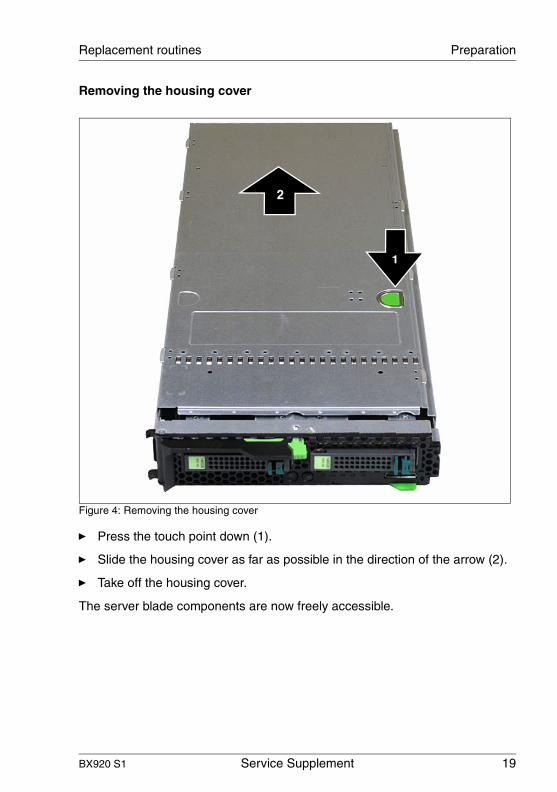
Removing the housing cover
Figure 4: Removing the housing cover
Ê Press the touch point down (1).
Ê Slide the housing cover as far as possible in the direction of the arrow (2).
Ê Take off the housing cover.
The server blade components are now freely accessible.
2
1

20 Service Supplement BX920 S1
Replacing processors Replacement routines
© c
ogn
itas.
Ge
sells
chft
für
Tech
nik
-Do
kum
enta
tion
mbH
200
9
Pfa
d: C
:\D
oku
men
te u
nd E
inst
ellu
nge
n\w
alte
r\E
ige
ne D
atei
en\
bx92
0s1\
Ser
vice
-Su
pple
men
t\InA
rbei
t\BX
920
_su
ppl.e
n\B
X9
20_s
upp
l_e
n.k0
4
4.2 Replacing processors
One or two processors can be installed in the server blade.
V CAUTION!
● Only use processors of the same type in a server blade. All proces-sors must have the same frequency and cache size. For multi-proces-sor mode use a suitable multi-processor operating system.
● Never touch the processor core.
● Be careful, that the thermal paste ist not damaged.
● Never install a processor without a heat sink as otherwise the proces-sor may overheat, causing the processor and system board to fail.
Requirements
– The server blade has been removed.– The server blade cover has been removed.

BX920 S1 Service Supplement 21
Replacement routines Replacing processors
Removing the heat sink
Figure 5: Removing the heat sink
Ê Loosen the four screws that fasten the processor heat sink to the processor, and remove the heat sink.
Removing the processor
Figure 6: Position of the processors
The following section illustrates how to remove CPU 1.
CPU 1
CPU 2
22 Service Supplement BX920 S1
Replacing processors Replacement routines
© c
ogn
itas.
Ge
sells
chft
für
Tech
nik
-Do
kum
enta
tion
mbH
200
9
Pfa
d: C
:\D
oku
men
te u
nd E
inst
ellu
nge
n\w
alte
r\E
ige
ne D
atei
en\
bx92
0s1\
Ser
vice
-Su
pple
men
t\InA
rbei
t\BX
920
_su
ppl.e
n\B
X9
20_s
upp
l_e
n.k0
4
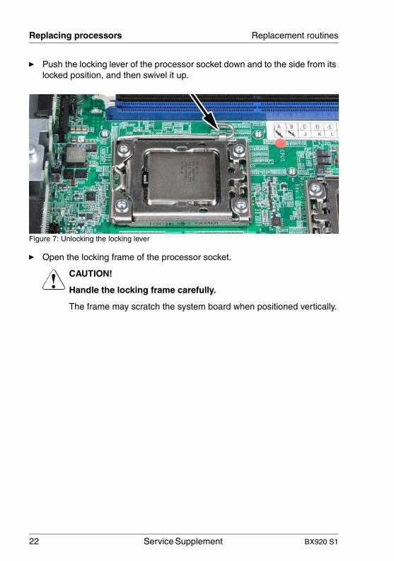
Ê Push the locking lever of the processor socket down and to the side from its locked position, and then swivel it up.
Figure 7: Unlocking the locking lever
Ê Open the locking frame of the processor socket.
V CAUTION!
Handle the locking frame carefully.
The frame may scratch the system board when positioned vertically.
BX920 S1 Service Supplement 23
Replacement routines Replacing processors
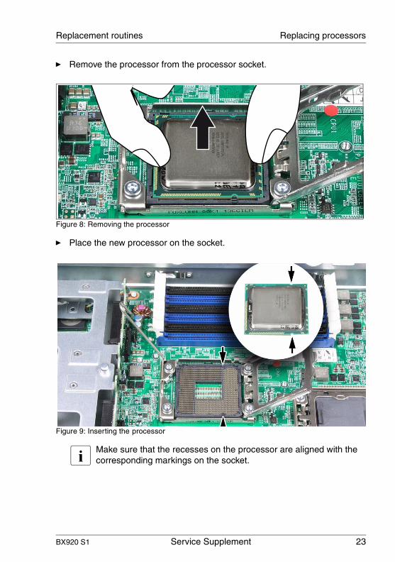
Ê Remove the processor from the processor socket.
Figure 8: Removing the processor
Ê Place the new processor on the socket.
Figure 9: Inserting the processor
I Make sure that the recesses on the processor are aligned with the corresponding markings on the socket.
24 Service Supplement BX920 S1
Replacing processors Replacement routines
© c
ogn
itas.
Ge
sells
chft
für
Tech
nik
-Do
kum
enta
tion
mbH
200
9
Pfa
d: C
:\D
oku
men
te u
nd E
inst
ellu
nge
n\w
alte
r\E
ige
ne D
atei
en\
bx92
0s1\
Ser
vice
-Su
pple
men
t\InA
rbei
t\BX
920
_su
ppl.e
n\B
X9
20_s
upp
l_e
n.k0
4
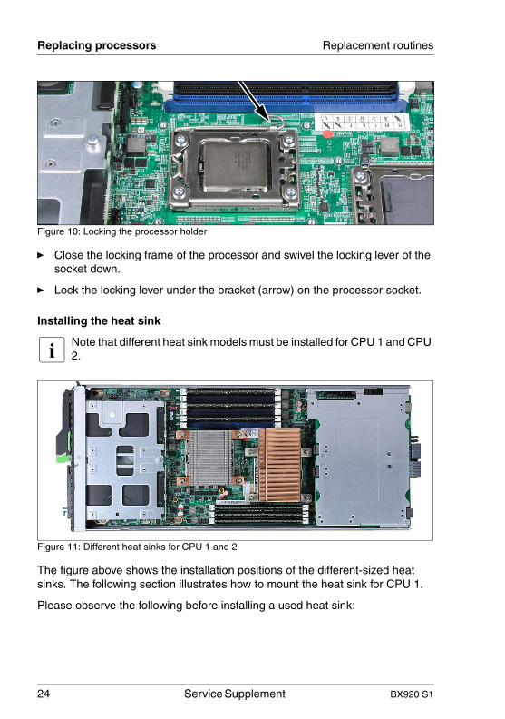
Figure 10: Locking the processor holder
Ê Close the locking frame of the processor and swivel the locking lever of the socket down.
Ê Lock the locking lever under the bracket (arrow) on the processor socket.
Installing the heat sink
I Note that different heat sink models must be installed for CPU 1 and CPU 2.
Figure 11: Different heat sinks for CPU 1 and 2
The figure above shows the installation positions of the different-sized heat sinks. The following section illustrates how to mount the heat sink for CPU 1.
Please observe the following before installing a used heat sink:
BX920 S1 Service Supplement 25
Replacement routines Replacing processors
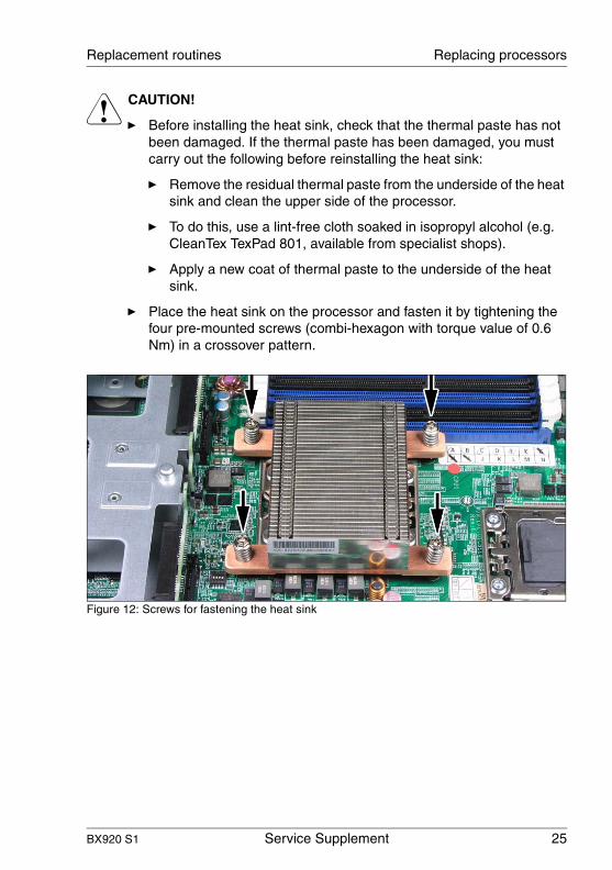
V CAUTION!
Ê Before installing the heat sink, check that the thermal paste has not been damaged. If the thermal paste has been damaged, you must carry out the following before reinstalling the heat sink:
Ê Remove the residual thermal paste from the underside of the heat sink and clean the upper side of the processor.
Ê To do this, use a lint-free cloth soaked in isopropyl alcohol (e.g. CleanTex TexPad 801, available from specialist shops).
Ê Apply a new coat of thermal paste to the underside of the heat sink.
Ê Place the heat sink on the processor and fasten it by tightening the four pre-mounted screws (combi-hexagon with torque value of 0.6 Nm) in a crossover pattern.
Figure 12: Screws for fastening the heat sink

26 Service Supplement BX920 S1
Replacing processors Replacement routines
© c
ogn
itas.
Ge
sells
chft
für
Tech
nik
-Do
kum
enta
tion
mbH
200
9
Pfa
d: C
:\D
oku
men
te u
nd E
inst
ellu
nge
n\w
alte
r\E
ige
ne D
atei
en\
bx92
0s1\
Ser
vice
-Su
pple
men
t\InA
rbei
t\BX
920
_su
ppl.e
n\B
X9
20_s
upp
l_e
n.k0
4
V CAUTION!
Take care to place the heat sink on the system board very precisely.Careless handling may damage conductors and render the system board useless.
Figure 13: Incorrect positioning of the heat sink

BX920 S1 Service Supplement 27
Replacement routines Replacing the SAS backplane
4.3 Replacing the SAS backplane
The server blade has two SAS backplanes to connect SAS/SATA hard disk modules to the system board.
Requirements
– The server blade is removed from the system unit.– The cover of the server blade is removed.– The corresponding hard disk module is removed.
The figure below shows the position of the SAS backplanes:"0" indicates the backplane of hard disk drive 0, "1" indicates the backplane of hard disk drive 1.
Bild 14: Mounting postions of the SAS backplanes
28 Service Supplement BX920 S1
Replacing the SAS backplane Replacement routines
© c
ogn
itas.
Ge
sells
chft
für
Tech
nik
-Do
kum
enta
tion
mbH
200
9
Pfa
d: C
:\D
oku
men
te u
nd E
inst
ellu
nge
n\w
alte
r\E
ige
ne D
atei
en\
bx92
0s1\
Ser
vice
-Su
pple
men
t\InA
rbei
t\BX
920
_su
ppl.e
n\B
X9
20_s
upp
l_e
n.k0
4
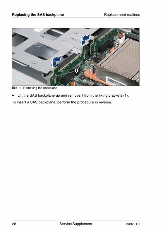
Bild 15: Removing the backplane
Ê Lift the SAS backplane up and remove it from the fixing brackets (1).
To insert a SAS backplane, perform the procedure in reverse.

BX920 S1 Service Supplement 29
Replacement routines Installing a mezzanine card
4.4 Installing a mezzanine card
One or two mezzanine cards can be installed in a PRIMERGY BX920 S1Server-Blade. Additional Fibre Channel, Ethernet and/or Infiniband I/O chan-nels can be set up using these cards.
All mezzanine cards have the same form factor.
Figure 16: Mezzanine card
The mezzanine cards are fastened on a special carrier and then connected together with the carrier to the system board.
The figure below shows an unpopulated carrier for mezzanine cards.

30 Service Supplement BX920 S1
Installing a mezzanine card Replacement routines
© c
ogn
itas.
Ge
sells
chft
für
Tech
nik
-Do
kum
enta
tion
mbH
200
9
Pfa
d: C
:\D
oku
men
te u
nd E
inst
ellu
nge
n\w
alte
r\E
ige
ne D
atei
en\
bx92
0s1\
Ser
vice
-Su
pple
men
t\InA
rbei
t\BX
920
_su
ppl.e
n\B
X9
20_s
upp
l_e
n.k0
4
Figure 17: Carrier for mezzanine cards
INote the numbering of the slots.
4.4.1 Population rules for mezzanine cards
Figure 18: Slot numbering for mezzanine cards
The slots of the mezzanine cards in the server blade are connected to certain connection blade slots on the back of the system unit. You therefore need to observe how the connection blade slots are populated on the back of the system unit when installing mezzanine cards.
2
1
Mezzanine card 1
Mezzanine card 2

BX920 S1 Service Supplement 31
Replacement routines Installing a mezzanine card
Figure 19: Slot numbering for connection blades
The figure below shows the connections of the connection blade slots to the slots for mezzanine cards.
System unitConnection blade slots Server Blade
Mezzanine card
Fabric 1 CB1:1 Gb Ethernet
CB2:1 Gb Ethernet
Onboard LAN controller
---
Fabric 2
CB3: 1 Gb Ethernet or
10 Gb Ethernetor
Fibre Channel
CB4: 1 Gb Ethernet or
10 Gb Ethernetor
Fibre Channel
Mezzanine card 1
Eth 1 Gb 4 portor
Eth 10 Gb 2 portor
FC 8 Gb 2 portor
IB 40 Gb 2 portor Infiniband (CB3/4)
Fabric 3
CB5: 1 Gb Ethernet or
10 Gb Ethernetor
Fibre Channel
CB6: 1 Gb Ethernet or
10 Gb Ethernetor
Fibre Channel Mezzanine card 2
Eth 1 Gb 4 portor
Eth 10 Gb 2 portor
FC 8 Gb 2 portor
IB 40 Gb 2 portor Infiniband (CB5/6)
Fabric 4
CB7:1 Gb Ethernet
CB8:1 Gb Ethernet Eth 1 Gb 4 port
orIB 40 Gb 2 portor Infiniband (CB7/8)
CB1
CB3
CB5
CB7
CB2
CB4
CB6
CB8
Fabric 1
Fabric 2
Fabric 3
Fabric 4

32 Service Supplement BX920 S1
Installing a mezzanine card Replacement routines
© c
ogn
itas.
Ge
sells
chft
für
Tech
nik
-Do
kum
enta
tion
mbH
200
9
Pfa
d: C
:\D
oku
men
te u
nd E
inst
ellu
nge
n\w
alte
r\E
ige
ne D
atei
en\
bx92
0s1\
Ser
vice
-Su
pple
men
t\InA
rbei
t\BX
920
_su
ppl.e
n\B
X9
20_s
upp
l_e
n.k0
4
As a result, the rules for populating the mezzanine card slots are as follows:
– If a 1 Gb Ethernet mezzanine card is installed in slot 1, at least one 1 Gb Ethernet connection blade must be installed in fabric 2.
– If a 10 Gb Ethernet mezzanine card is installed in slot 1, at least one 10 Gb Ethernet connection blade must be installed in fabric 2.
System unitConnection blade slots Server Blade
Mezzanine card
Fabric 1 CB1:1 Gb Ethernet
CB2:1 Gb Ethernet
Onboard LAN controller
---
Fabric 2CB3:
1 Gb Ethernet CB4:
1 Gb Ethernet Mezzanine
card 1Eth 1 Gb 4 port
Fabric 3CB5: CB6:
Mezzanine card 2
Fabric 4CB7: CB8:
System unitConnection blade slots Server Blade
Mezzanine card
Fabric 1 CB1:1 Gb Ethernet
CB2:1 Gb Ethernet
Onboard LAN controller
---
Fabric 2CB3:
10 Gb Ethernet CB4:
10 Gb Ethernet Mezzanine
card 1Eth 10 Gb 2 port
Fabric 3CB5: CB6:
Mezzanine card 2
Fabric 4CB7: CB8:

BX920 S1 Service Supplement 33
Replacement routines Installing a mezzanine card
– If an 8 Gb Fibre Channel mezzanine card is installed in slot 1, at least one Fibre Channel connection blade must be installed in fabric 2.
– If an 40 Gb Infiniband mezzanine card is installed in slot 1, an Infiniband con-nection blade must be installed in fabric 2.
I In this case only one of two ports of the mezzanine card will be utili-zed and connected to the connection blade in fabric 2.
System unitConnection blade slots Server Blade
Mezzanine card
Fabric 1 CB1:1 Gb Ethernet
CB2:1 Gb Ethernet
Onboard LAN controller
---
Fabric 2CB3:
Fibre ChannelCB4:
Fibre ChannelMezzanine
card 1FC 8 Gb 2 port
Fabric 3CB5: CB6:
Mezzanine card 2
Fabric 4CB7: CB8:
System unitConnection blade slots Server Blade
Mezzanine card
Fabric 1 CB1:1 Gb Ethernet
CB2:1 Gb Ethernet
Onboard LAN controller
---
Fabric 2 Infiniband (CB3/4)Mezzanine
card 1IB 40 Gb 2 port
Fabric 3CB5: CB6:
Mezzanine card 2
Fabric 4CB7: CB8:

34 Service Supplement BX920 S1
Installing a mezzanine card Replacement routines
© c
ogn
itas.
Ge
sells
chft
für
Tech
nik
-Do
kum
enta
tion
mbH
200
9
Pfa
d: C
:\D
oku
men
te u
nd E
inst
ellu
nge
n\w
alte
r\E
ige
ne D
atei
en\
bx92
0s1\
Ser
vice
-Su
pple
men
t\InA
rbei
t\BX
920
_su
ppl.e
n\B
X9
20_s
upp
l_e
n.k0
4
– If a 1 Gb Ethernet mezzanine card is installed in slot 2, at least one 1 Gb Ethernet connection blade must be installed in fabric 3 or in fabric 4.
– If a 10 Gb Ethernet mezzanine card is installed in slot 2, at least one 10 Gb Ethernet connection blade must be installed in fabric 3.
System unitConnection blade slots Server Blade
Mezzanine card
Fabric 1 CB1:1 Gb Ethernet
CB2:1 Gb Ethernet
Onboard LAN controller
---
Fabric 2CB3: CB4: Mezzanine
card 1
Fabric 3CB5:
1 Gb Ethernet CB6:
1 Gb Ethernet Mezzanine
card 2Eth 1 Gb 4 port
Fabric 4CB7:
1 Gb Ethernet CB8:
1 Gb Ethernet
System unitConnection blade slots Server Blade
Mezzanine card
Fabric 1 CB1:1 Gb Ethernet
CB2:1 Gb Ethernet
Onboard LAN controller
---
Fabric 2CB3: CB4: Mezzanine
card 1
Fabric 3CB5:
10 Gb Ethernet CB6:
10 Gb Ethernet Mezzanine
card 2Eth 10 Gb 2 port
Fabric 4CB7: CB8:

BX920 S1 Service Supplement 35
Replacement routines Installing a mezzanine card
– If an 8 Gb Fibre Channel mezzanine card is installed in slot 2, at least one Fibre Channel connection blade must be installed in fabric 3.
– If an 40 Gb Infiniband mezzanine card is installed in slot 2, Infiniband con-nection blades should be installed in fabrics 3 and 4.
I In this case the dual ports of the mezzanine card will be available and one of two ports will be connected to connection blade in fabric 3, the other one will be connected to connection blade in fabric 4.
System unitConnection blade slots Server Blade
Mezzanine card
Fabric 1 CB1:1 Gb Ethernet
CB2:1 Gb Ethernet
Onboard LAN controller
---
Fabric 2CB3: CB4: Mezzanine
card 1
Fabric 3CB5:
Fibre ChannelCB6:
Fibre ChannelMezzanine
card 2FC 8 Gb 2 port
Fabric 4CB7: CB8:
System unitConnection blade slots Server Blade
Mezzanine card
Fabric 1 CB1:1 Gb Ethernet
CB2:1 Gb Ethernet
Onboard LAN controller
---
Fabric 2CB3: CB4: Mezzanine
card 1
Fabric 3 Infiniband (CB5/6)Mezzanine
card 2IB 40 Gb 2 port
Fabric 4 Infiniband (CB7/8)
36 Service Supplement BX920 S1
Installing a mezzanine card Replacement routines
© c
ogn
itas.
Ge
sells
chft
für
Tech
nik
-Do
kum
enta
tion
mbH
200
9
Pfa
d: C
:\D
oku
men
te u
nd E
inst
ellu
nge
n\w
alte
r\E
ige
ne D
atei
en\
bx92
0s1\
Ser
vice
-Su
pple
men
t\InA
rbei
t\BX
920
_su
ppl.e
n\B
X9
20_s
upp
l_e
n.k0
4
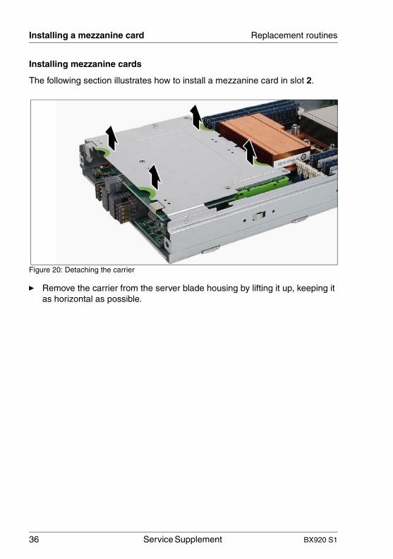
Installing mezzanine cards
The following section illustrates how to install a mezzanine card in slot 2.
Figure 20: Detaching the carrier
Ê Remove the carrier from the server blade housing by lifting it up, keeping it as horizontal as possible.
BX920 S1 Service Supplement 37
Replacement routines Installing a mezzanine card
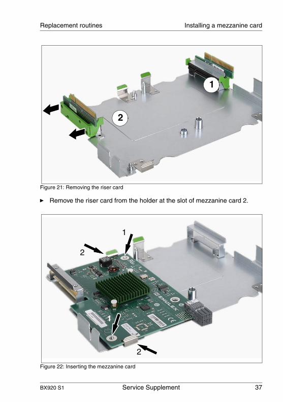
Figure 21: Removing the riser card
Ê Remove the riser card from the holder at the slot of mezzanine card 2.
Figure 22: Inserting the mezzanine card
1
2
1
2
1
2

38 Service Supplement BX920 S1
Installing a mezzanine card Replacement routines
© c
ogn
itas.
Ge
sells
chft
für
Tech
nik
-Do
kum
enta
tion
mbH
200
9
Pfa
d: C
:\D
oku
men
te u
nd E
inst
ellu
nge
n\w
alte
r\E
ige
ne D
atei
en\
bx92
0s1\
Ser
vice
-Su
pple
men
t\InA
rbei
t\BX
920
_su
ppl.e
n\B
X9
20_s
upp
l_e
n.k0
4
Ê Place the mezzanine card on the two guide pins (1) at the slot of mezzanine card 2 and press the mezzanine card down so that it clicks into place bet-ween the two clips (2).
Figure 23: Reconnecting the riser card
Ê Connect the riser card to the mezzanine card connector. Make sure that the green clips click into place.
I Mezzanine card 1 is fastened to the carrier with the component side facing downward. Mezzanine card 1 is otherwise installed in the same way as mezzanine card 2.
Figure 24: Installing the carrier

BX920 S1 Service Supplement 39
Replacement routines Installing a mezzanine card
Ê Install the carrier with the mezzanine cards in the server blade housing. As you do this, the riser cards are inserted in the corresponding system board slots.
Make sure that the coding on the carrier matches that on the server blade housing.

40 Service Supplement BX920 S1
Installing/removing a TPM Replacement routines
© c
ogn
itas.
Ge
sells
chft
für
Tech
nik
-Do
kum
enta
tion
mbH
200
9
Pfa
d: C
:\D
oku
men
te u
nd E
inst
ellu
nge
n\w
alte
r\E
ige
ne D
atei
en\
bx92
0s1\
Ser
vice
-Su
pple
men
t\InA
rbei
t\BX
920
_su
ppl.e
n\B
X9
20_s
upp
l_e
n.k0
4
4.5 Installing/removing a TPM
TPMs (Trusted Platform Module) can be installed in the server blade.
4.5.1 Installing a TPM
Figure 25: Scope of delivery of TPM
The figure above shows the contents of the TPM installation kit.
1 TPM (Trusted Platform Module)
2 TPM spacer
3 Special screw for the TPM module
4 Insert bit for special screw
1 2 3 4

BX920 S1 Service Supplement 41
Replacement routines Installing/removing a TPM
Figure 26: TPM spacer
Ê Insert the spacer in the recess next to the multi-pin connector for the TPM. The plastic spacer must audibly click into place.
Figure 27: Trusted Platform Module
Ê Connect the TPM to the multi-pin connector.
42 Service Supplement BX920 S1
Installing/removing a TPM Replacement routines
© c
ogn
itas.
Ge
sells
chft
für
Tech
nik
-Do
kum
enta
tion
mbH
200
9
Pfa
d: C
:\D
oku
men
te u
nd E
inst
ellu
nge
n\w
alte
r\E
ige
ne D
atei
en\
bx92
0s1\
Ser
vice
-Su
pple
men
t\InA
rbei
t\BX
920
_su
ppl.e
n\B
X9
20_s
upp
l_e
n.k0
4
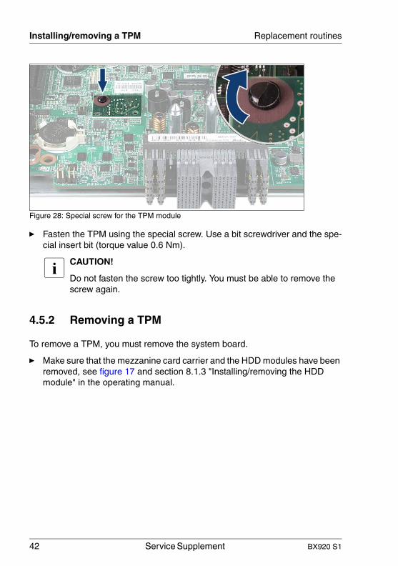
Figure 28: Special screw for the TPM module
Ê Fasten the TPM using the special screw. Use a bit screwdriver and the spe-cial insert bit (torque value 0.6 Nm).
I CAUTION!
Do not fasten the screw too tightly. You must be able to remove the screw again.
4.5.2 Removing a TPM
To remove a TPM, you must remove the system board.
Ê Make sure that the mezzanine card carrier and the HDD modules have been removed, see figure 17 and section 8.1.3 "Installing/removing the HDD module" in the operating manual.

BX920 S1 Service Supplement 43
Replacement routines Installing/removing a TPM
Ê Remove the screw (1).
Ê Slide the system board as far as it will go in the direction of the arrow (2).
Ê Lift the system board up to remove it.
Ê Reinstall the system board. The procedure for installing the system board is the same as for removing it, except in reverse order.
Ê Remove the TPM screw from the underside of the system board using a fine slotted screwdriver (watchmaker screwdriver). The arrow indicates the slot on the bot-tom of the TPM screw.
Ê Disconnect the TPM from the slot.

44 Service Supplement BX920 S1
Installing/removing a TPM Replacement routines
© c
ogn
itas.
Ge
sells
chft
für
Tech
nik
-Do
kum
enta
tion
mbH
200
9
Pfa
d: C
:\D
oku
men
te u
nd E
inst
ellu
nge
n\w
alte
r\E
ige
ne D
atei
en\
bx92
0s1\
Ser
vice
-Su
pple
men
t\InA
rbei
t\BX
920
_su
ppl.e
n\B
X9
20_s
upp
l_e
n.k0
4

BX920 S1 Service Supplement 45
5 Diagnosis and maintenance
5.1 Recovering the Server Blade BIOS
This section describes the procedure you can use to recover a server blade BIOS in the event of an error.
V CAUTION!
This procedure is only intended for use in the event of an error.
Requirements
– The system unit is connected to the power supply system.– The server blade is switched off.– An external USB memory stick is available.
Creating a BIOS Flash USB memory stick
Ê Expand the BIOS update ZIP archive file on the hard disk of a PC.
I You will find the data for creating the BIOS Flash USB memory stick in the software pool athttp://support.ts.fujitsu.com/com/support/downloads.html.
Ê Insert an empty USB memory stick into an USB host connector of the PC.
Ê Copy the content of the ZIP archive file to the USB memory stick to create a BIOS Flash USB memory stick.
First option: Recovering the server blade BIOS via management blade
Ê Log in to the management blade GUI.
Ê Select the server blade for BIOS recovery.
Ê Click on Configuration
Ê Click on Boot Options.

46 Service Supplement BX920 S1
Recovering the Server Blade BIOS Diagnosis and maintenance
© c
ogn
itas.
Ge
sells
chft
für
Tech
nik
-Do
kum
enta
tion
mbH
200
9
Pfa
d: C
:\D
oku
men
te u
nd E
inst
ellu
nge
n\w
alte
r\E
ige
ne D
atei
en\
bx92
0s1\
Ser
vice
-Su
pple
men
t\InA
rbei
t\BX
920
_su
ppl.e
n\B
X9
20_s
upp
l_e
n.k0
5
Bild 29: Boot Options menu
Ê Select BIOS Recovery Flash Bit Enabled.
Ê Connect the monitor, keyboard, mouse and USB memory stick to the port on the front of the server blade using the Y cable, see the Operating Manual.
Ê Switch on the server blade, see the Operating Manual.
After a short beep, the BIOS upload is executed. The status of the Flash operation is displayed on screen. Once the Flash operation is complete, information on how to proceed is displayed:
Ê Switch off the server blade.
Ê Remove the Y cable.
Bild 30: Boot Options menu
Ê Deselect BIOS Recovery Flash Bit Enabled in the management blade Boot Options menu.
Ê Switch the server blade on.
Ê You can now put the server blade back into operation.
Second option: Recovering the server blade BIOS via USB memory stick
Ê Remove the server blade from the blade server chassis and open it as described in section "Removing the housing cover" on page 19.
BX920 S1 Service Supplement 47
Diagnosis and maintenance Recovering the Server Blade BIOS
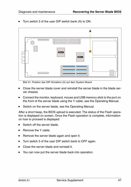
Ê Turn switch 3 of the user DIP switch bank (A) to ON.
Bild 31: Position des DIP-Schalters (A) auf dem System Board
Ê Close the server blade cover and reinstall the server blade in the blade ser-ver chassis.
Ê Connect the monitor, keyboard, mouse and USB memory stick to the port on the front of the server blade using the Y cable, see the Operating Manual.
Ê Switch on the server blade, see the Operating Manual.
After a short beep, the BIOS upload is executed. The status of the Flash opera-tion is displayed on screen. Once the Flash operation is complete, information on how to proceed is displayed:
Ê Switch off the server blade.
Ê Remove the Y cable.
Ê Remove the server blade again and open it.
Ê Turn switch 3 of the user DIP switch bank to OFF again.
Ê Close the server blade and reinstall it.
Ê You can now put the server blade back into operation.
CPU 1
CPU 2
A

48 Service Supplement BX920 S1
Recovering the Server Blade BIOS Diagnosis and maintenance
© c
ogn
itas.
Ge
sells
chft
für
Tech
nik
-Do
kum
enta
tion
mbH
200
9
Pfa
d: C
:\D
oku
men
te u
nd E
inst
ellu
nge
n\w
alte
r\E
ige
ne D
atei
en\
bx92
0s1\
Ser
vice
-Su
pple
men
t\InA
rbei
t\BX
920
_su
ppl.e
n\B
X9
20_s
upp
l_e
n.k0
5
BX920 S1 Service Supplement 49
IndexBbattery 13BIOS
recovering 45update 46, 47
Ccadmium 13connection blade 30
slots 31consumables 15CPU 21
DDIP-Schalter 47documentation 5
Eelectrostatic discharge (ESD) 14electrostatic discharge (ESD), compo-
nents might be damaged 14environmental protection 15
Fform factor 29
Hheat sink 20
Llabels 15lead 13lithium battery 13
Mmeaning of the symbols 7mercury 13mezzanine card 29
form factor 29multiprocessor mode 20
Nnotational conventions 7notes on safety 11
Ppackaging 15processors 21
installing/removing 20
Rrecovery
BIOS 45recycling, of devices 16return, of devices 16
SSAS backplane 28saving energy 15server blade
opening 19removing from system unit 17
Ttarget group 5thermal paste 25touch point 14, 19
YY cable 46, 47

© c
ogn
itas.
Ges
ells
chft
für
Tech
nik-
Dok
um
enta
tion
mbH
200
9 P
fad
: C:\D
oku
men
te u
nd E
inst
ellu
nge
n\w
alte
r\E
igen
e D
atei
en\
bx92
0s1\
Ser
vice
-Su
pple
men
t\InA
rbei
t\B
X9
20_s
upp
l.en\
BX
920
_sup
pl_e
n.si
x