primergy bx600 s3 blade server system unit hardware guide · pdf filechapter 2 security this...
TRANSCRIPT
1
PRIMERGY BX600 S3 Blade Server System Unit Hardware Guide
Areas Covered
Before Reading This Manual
This section explains the notes for your safety and conventions used in this manual. Make
sure to read this section.
Chapter 1 Component Names and Functions
This chapter explains the component names and functions of the server.
Chapter 2 Security
This chapter explains the security features that are provided in order to protect the server
hardware and software from theft.
Chapter 3 Standard Operations
This chapter explains such standard operations as turning the server ON/OFF and inserting
and ejecting floppy disks.
Chapter 4 Installing Options
This chapter explains how to install and remove various options to the Chassis.
Chapter 5 Maintenance
This chapter explains how to perform daily maintenance and the maintenance information.
Chapter 6 Technical Information
This chapter explains the specifications and operational notes of the Chassis and optional
devices.
2
Before Reading This Manual
For Your Safety...
This manual contains important information, required to operate this product safely.
Thoroughly review the information in this manual before using this product. Especially note the points under "Safety Precautions" provided
with the Chassis or Server Blade, and only operate this product with a complete understanding of the material provided.
This manual and "Safety Precautions" should be kept in an easy-to-access location for quick reference when using this product.
Data Backup
To protect data stored in this product (including basic software (OS) and application software), perform backup and other necessary
operations. Note that data protection is not guaranteed when repairs are performed. It is the customer's responsibility to maintain backup
copies in advance.
In case of data loss, Fujitsu assumes no liability for data maintenance or restoration and damages that occur as a result of the data loss for any
reason, except for items covered under warranty.
High Safety
This product is designed, developed and manufactured as contemplated for general use, including without limitation, general office use,
personal use, household use, and ordinary industrial use, but is not designed, developed and manufactured as contemplated for use
accompanying fatal risks or dangers that, unless extremely high safety is secured, could lead directly to death, personal injury, severe physical
damage, or other loss (hereinafter "High Safety Required Use"), including without limitation, nuclear reaction control in nuclear facility,
aircraft flight control, air traffic control, mass transport control, medical life support system, missile launch control in weapon system. You
shall not use this Product without securing the sufficient safety required for the High Safety Required Use. If you wish to use this product for
High Safety Required Use, please consult with our sales representatives in charge before such use.
Problems may occur with this product in the event of an instantaneous voltage drop of the power supply due to lightning, etc. To prevent an
instantaneous voltage drop of the power supply, we recommend that you use an uninterruptible power supply system.
PRIMERGY BX600 S3 Blade Server System Unit Hardware Guide
Contents
This manual supports operation of the PRIMERGY BX600 S3 Blade Server System Unit. When
operating with other Chassis, refer to the relevant manuals in the Fujitsu PRIMERGY website (http://
primergy.fujitsu.com).
Remarks
■ Warning Descriptions
Various symbols are used throughout this manual. These are provided to emphasize important points for
your safety and that of others. The following are the symbols and their meanings. It is important to fully
understand these symbols before reading this manual.
The following symbols are used indicate the type of warning or cautions being described.
■ Symbols
Symbols used in this manual have the following meanings:
■ Key Descriptions / Operations
Keys are described by their representative characters instead of their exact key face appearance, as show
below.
E.g.: [Ctrl] key, [Enter] key, [→] key, etc.
The following indicate the pressing of several keys at once:
E.g.: [Ctrl] + [F3] key, [Shift] + [↑] key, etc.
Failure to observe this warning may cause serious injury or death, and/or destroy the system.
Failure to observe this warning may lead to injury, destruction of the system, or loss of data.
A triangle mark emphasizes the urgency of the WARNING and CAUTION. Details are
described next to the triangle.
A barred circle ( ) warns against certain actions (Do Not). Details are described next to the
circle.
A black circle indicates actions that must be taken. Details are described next to the black circle.
Expression Meaning
These sections explain prohibited actions and points to note when using this product. Make sure
to read these sections.
These sections explain information needed to operate the hardware and software properly.
Make sure to read these sections.
→ This mark indicates reference pages or manuals.
3
4
■ DVD-ROM Drive Descriptions
In this manual, a DVD-ROM drive is described as CD/DVD drive.
■ Entering Commands (Keys)
Command entries are displayed in the following way:
• In the spaces indicated with the "↑" mark, press the [Space] key once.
• When using Windows, commands are not case sensitive.
• CD/DVD drive names are shown as [CD/DVD drive]. Enter your drive name according to your
environment.
[CD/DVD drive]:\setup.exe
■ Screen Shots and Figures
Screen shots and figures are used as visual aids throughout this manual. Windows, screens, and file
names may vary depending on the OS, software, or configuration of the server used. Figures in this
manual may not show cables that are actually connected for convenience of explanation.
■ Consecutive Operations
Consecutive operations are described by connecting them with "–".
Example: Procedure of clicking the [Start] button, pointing to [Programs], and clicking [Accessories]
↓
Click [Start] – [All Programs] – [Accessories].
PRIMERGY BX600 S3 Blade Server System Unit Hardware Guide
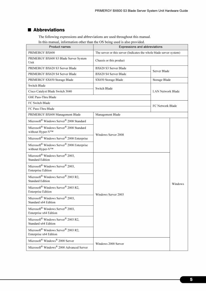
■ Abbreviations
The following expressions and abbreviations are used throughout this manual.
In this manual, information other than the OS being used is also provided.
Product names Expressions and abbreviations
PRIMERGY BX600 The server or this server (Indicates the whole blade server system)
PRIMERGY BX600 S3 Blade Server System
UnitChassis or this product
PRIMERGY BX620 S3 Server Blade BX620 S3 Server BladeServer Blade
PRIMERGY BX620 S4 Server Blade BX620 S4 Server Blade
PRIMERGY SX650 Storage Blade SX650 Storage Blade Storage Blade
Switch Blade Switch Blade
LAN Network BladeCisco Catalyst Blade Switch 3040
GbE Pass-Thru Blade
FC Switch BladeFC Network Blade
FC Pass-Thru Blade
PRIMERGY BX600 Management Blade Management Blade
Microsoft® Windows Server® 2008 Standard
Windows Server 2008
Windows
Microsoft® Windows Server® 2008 Standard
without Hyper-V™
Microsoft® Windows Server® 2008 Enterprise
Microsoft® Windows Server® 2008 Enterprise
without Hyper-V™
Microsoft® Windows Server® 2003, Standard Edition
Windows Server 2003
Microsoft® Windows Server® 2003, Enterprise Edition
Microsoft® Windows Server® 2003 R2, Standard Edition
Microsoft® Windows Server® 2003 R2, Enterprise Edition
Microsoft® Windows Server® 2003, Standard x64 Edition
Microsoft® Windows Server® 2003, Enterprise x64 Edition
Microsoft® Windows Server® 2003 R2, Standard x64 Edition
Microsoft® Windows Server® 2003 R2, Enterprise x64 Edition
Microsoft® Windows® 2000 ServerWindows 2000 Server
Microsoft® Windows® 2000 Advanced Server
5
6
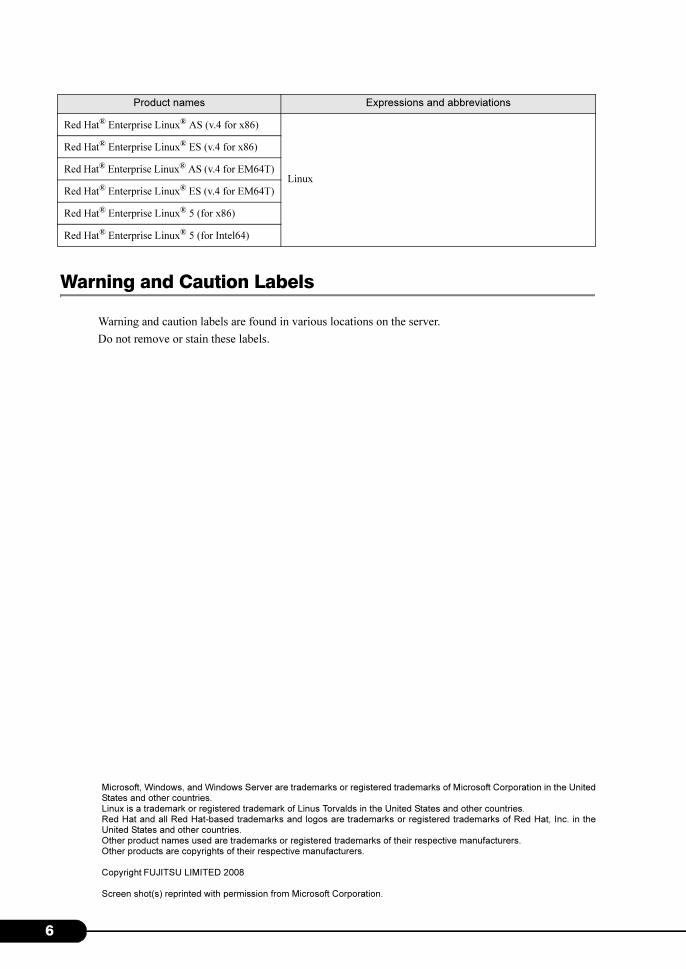
Warning and Caution Labels
Warning and caution labels are found in various locations on the server.
Do not remove or stain these labels.
Microsoft, Windows, and Windows Server are trademarks or registered trademarks of Microsoft Corporation in the United States and other countries. Linux is a trademark or registered trademark of Linus Torvalds in the United States and other countries. Red Hat and all Red Hat-based trademarks and logos are trademarks or registered trademarks of Red Hat, Inc. in the United States and other countries.Other product names used are trademarks or registered trademarks of their respective manufacturers. Other products are copyrights of their respective manufacturers.
Copyright FUJITSU LIMITED 2008
Screen shot(s) reprinted with permission from Microsoft Corporation.
Red Hat® Enterprise Linux® AS (v.4 for x86)
Linux
Red Hat® Enterprise Linux® ES (v.4 for x86)
Red Hat® Enterprise Linux® AS (v.4 for EM64T)
Red Hat® Enterprise Linux® ES (v.4 for EM64T)
Red Hat® Enterprise Linux® 5 (for x86)
Red Hat® Enterprise Linux® 5 (for Intel64)
Product names Expressions and abbreviations
PRIMERGY BX600 S3 Blade Server System Unit Hardware Guide
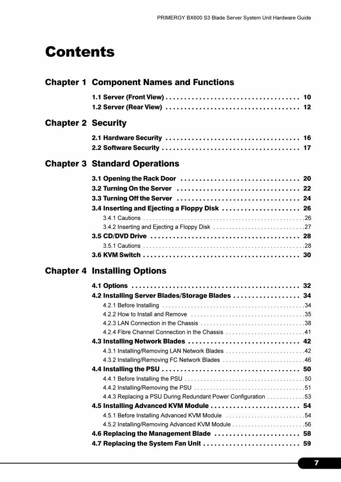
Contents
Chapter 1 Component Names and Functions
1.1 Server (Front View) . . . . . . . . . . . . . . . . . . . . . . . . . . . . . . . . . . . . 10
1.2 Server (Rear View) . . . . . . . . . . . . . . . . . . . . . . . . . . . . . . . . . . . . 12
Chapter 2 Security
2.1 Hardware Security . . . . . . . . . . . . . . . . . . . . . . . . . . . . . . . . . . . . 16
2.2 Software Security . . . . . . . . . . . . . . . . . . . . . . . . . . . . . . . . . . . . . 17
Chapter 3 Standard Operations
3.1 Opening the Rack Door . . . . . . . . . . . . . . . . . . . . . . . . . . . . . . . . 20
3.2 Turning On the Server . . . . . . . . . . . . . . . . . . . . . . . . . . . . . . . . . 22
3.3 Turning Off the Server . . . . . . . . . . . . . . . . . . . . . . . . . . . . . . . . . 24
3.4 Inserting and Ejecting a Floppy Disk . . . . . . . . . . . . . . . . . . . . . 26
3.4.1 Cautions . . . . . . . . . . . . . . . . . . . . . . . . . . . . . . . . . . . . . . . . . . . . . . . . . . .26
3.4.2 Inserting and Ejecting a Floppy Disk . . . . . . . . . . . . . . . . . . . . . . . . . . . . .27
3.5 CD/DVD Drive . . . . . . . . . . . . . . . . . . . . . . . . . . . . . . . . . . . . . . . . 28
3.5.1 Cautions . . . . . . . . . . . . . . . . . . . . . . . . . . . . . . . . . . . . . . . . . . . . . . . . . . .28
3.6 KVM Switch . . . . . . . . . . . . . . . . . . . . . . . . . . . . . . . . . . . . . . . . . . 30
Chapter 4 Installing Options
4.1 Options . . . . . . . . . . . . . . . . . . . . . . . . . . . . . . . . . . . . . . . . . . . . . 32
4.2 Installing Server Blades/Storage Blades . . . . . . . . . . . . . . . . . . 34
4.2.1 Before Installing . . . . . . . . . . . . . . . . . . . . . . . . . . . . . . . . . . . . . . . . . . . . .34
4.2.2 How to Install and Remove . . . . . . . . . . . . . . . . . . . . . . . . . . . . . . . . . . . .35
4.2.3 LAN Connection in the Chassis . . . . . . . . . . . . . . . . . . . . . . . . . . . . . . . . .38
4.2.4 Fibre Channel Connection in the Chassis . . . . . . . . . . . . . . . . . . . . . . . . .41
4.3 Installing Network Blades . . . . . . . . . . . . . . . . . . . . . . . . . . . . . . 42
4.3.1 Installing/Removing LAN Network Blades . . . . . . . . . . . . . . . . . . . . . . . . .42
4.3.2 Installing/Removing FC Network Blades . . . . . . . . . . . . . . . . . . . . . . . . . .46
4.4 Installing the PSU . . . . . . . . . . . . . . . . . . . . . . . . . . . . . . . . . . . . . 50
4.4.1 Before Installing the PSU . . . . . . . . . . . . . . . . . . . . . . . . . . . . . . . . . . . . . .50
4.4.2 Installing/Removing the PSU . . . . . . . . . . . . . . . . . . . . . . . . . . . . . . . . . . .51
4.4.3 Replacing a PSU During Redundant Power Configuration . . . . . . . . . . . .53
4.5 Installing Advanced KVM Module . . . . . . . . . . . . . . . . . . . . . . . . 54
4.5.1 Before Installing Advanced KVM Module . . . . . . . . . . . . . . . . . . . . . . . . .54
4.5.2 Installing/Removing Advanced KVM Module . . . . . . . . . . . . . . . . . . . . . . .56
4.6 Replacing the Management Blade . . . . . . . . . . . . . . . . . . . . . . . 58
4.7 Replacing the System Fan Unit . . . . . . . . . . . . . . . . . . . . . . . . . . 59
7
8
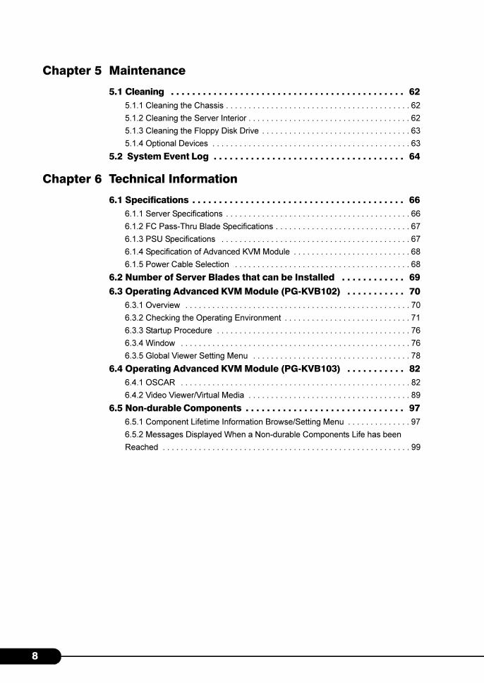
Chapter 5 Maintenance
5.1 Cleaning . . . . . . . . . . . . . . . . . . . . . . . . . . . . . . . . . . . . . . . . . . . . 62
5.1.1 Cleaning the Chassis . . . . . . . . . . . . . . . . . . . . . . . . . . . . . . . . . . . . . . . . . 62
5.1.2 Cleaning the Server Interior . . . . . . . . . . . . . . . . . . . . . . . . . . . . . . . . . . . . 62
5.1.3 Cleaning the Floppy Disk Drive . . . . . . . . . . . . . . . . . . . . . . . . . . . . . . . . . 63
5.1.4 Optional Devices . . . . . . . . . . . . . . . . . . . . . . . . . . . . . . . . . . . . . . . . . . . . 63
5.2 System Event Log . . . . . . . . . . . . . . . . . . . . . . . . . . . . . . . . . . . . 64
Chapter 6 Technical Information
6.1 Specifications . . . . . . . . . . . . . . . . . . . . . . . . . . . . . . . . . . . . . . . . 66
6.1.1 Server Specifications . . . . . . . . . . . . . . . . . . . . . . . . . . . . . . . . . . . . . . . . . 66
6.1.2 FC Pass-Thru Blade Specifications . . . . . . . . . . . . . . . . . . . . . . . . . . . . . . 67
6.1.3 PSU Specifications . . . . . . . . . . . . . . . . . . . . . . . . . . . . . . . . . . . . . . . . . . 67
6.1.4 Specification of Advanced KVM Module . . . . . . . . . . . . . . . . . . . . . . . . . . 68
6.1.5 Power Cable Selection . . . . . . . . . . . . . . . . . . . . . . . . . . . . . . . . . . . . . . . 68
6.2 Number of Server Blades that can be Installed . . . . . . . . . . . . 69
6.3 Operating Advanced KVM Module (PG-KVB102) . . . . . . . . . . . 70
6.3.1 Overview . . . . . . . . . . . . . . . . . . . . . . . . . . . . . . . . . . . . . . . . . . . . . . . . . . 70
6.3.2 Checking the Operating Environment . . . . . . . . . . . . . . . . . . . . . . . . . . . . 71
6.3.3 Startup Procedure . . . . . . . . . . . . . . . . . . . . . . . . . . . . . . . . . . . . . . . . . . . 76
6.3.4 Window . . . . . . . . . . . . . . . . . . . . . . . . . . . . . . . . . . . . . . . . . . . . . . . . . . . 76
6.3.5 Global Viewer Setting Menu . . . . . . . . . . . . . . . . . . . . . . . . . . . . . . . . . . . 78
6.4 Operating Advanced KVM Module (PG-KVB103) . . . . . . . . . . . 82
6.4.1 OSCAR . . . . . . . . . . . . . . . . . . . . . . . . . . . . . . . . . . . . . . . . . . . . . . . . . . . 82
6.4.2 Video Viewer/Virtual Media . . . . . . . . . . . . . . . . . . . . . . . . . . . . . . . . . . . . 89
6.5 Non-durable Components . . . . . . . . . . . . . . . . . . . . . . . . . . . . . . 97
6.5.1 Component Lifetime Information Browse/Setting Menu . . . . . . . . . . . . . . 97
6.5.2 Messages Displayed When a Non-durable Components Life has been
Reached . . . . . . . . . . . . . . . . . . . . . . . . . . . . . . . . . . . . . . . . . . . . . . . . . . . . . . . 99
Chapter 1
Component Names and Functions
This chapter explains the component names and
functions of the server.
1.1 Server (Front View) . . . . . . . . . . . . . . . . . . . . . . . . . . . . . 10
1.2 Server (Rear View) . . . . . . . . . . . . . . . . . . . . . . . . . . . . . 12
9

1
Chapter 1 Component Names and Functions
1.1 Server (Front View)
The following are the component names of the server (front view).
1
* The Server Blade diagram shown in this manual shows one possible setup pattern.
14
15
2
3
4
5
67
8
11
10
9
13
12
1 Server blade slots 1 – 10
This is where Server Blades, Storage Blades, or dummy
Server Blades are installed. The slot numbers are
displayed on the Chassis.
A total of nine dummy Server Blades come included
with the Chassis by default. Server blades are not
installed with the Chassis by default.
2 Main power LED ( )
3 Main power switch
Pressing this switch starts the system fan unit and the
Network Blade.
Do not turn the server off when the hard disk
access display LED is on. The data stored on the
hard disk may be damaged.
LED status Server Status
ON (Green) The main power supply of the
Chassis is ON.
ON (Amber) The AC power is ON but the main
power supply of the Chassis is OFF.
OFF The main power supply or the AC
power of the Chassis is OFF.
4 Front maintenance LED ( )
This works in conjunction with the rear maintenance
LED and lights/blinks in the following situations.
5 Front maintenance switch
Pressing this switch turns the front and rear maintenance
LEDs ON.
ID
LED status Server Status
Blinking
(Amber)
An error in an internal component of
the server has been detected.
Contact an office listed in the
"Contact Information" of "Start
Guide" or device administrator.
ON (Amber) This can be turned on by pressing the
front maintenance switch or using the
"System Indication LED Display"
function in the management terminal.
For details about the "System
Indication LED Display" function
refer to "BX600 Management Blade
Hardware Guide" and "ServerView
User's Guide".
0
PRIMERGY BX600 S3 Blade Server System Unit Hardware Guide
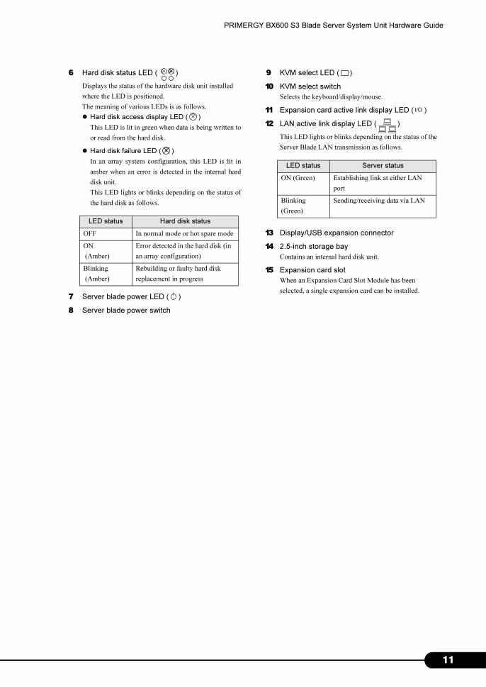
6 Hard disk status LED ( )
Displays the status of the hardware disk unit installed
where the LED is positioned.
The meaning of various LEDs is as follows.
� Hard disk access display LED ( )
This LED is lit in green when data is being written to
or read from the hard disk.
� Hard disk failure LED ( )
In an array system configuration, this LED is lit in
amber when an error is detected in the internal hard
disk unit.
This LED lights or blinks depending on the status of
the hard disk as follows.
7 Server blade power LED ( )
8 Server blade power switch
LED status Hard disk status
OFF In normal mode or hot spare mode
ON
(Amber)
Error detected in the hard disk (in
an array configuration)
Blinking
(Amber)
Rebuilding or faulty hard disk
replacement in progress
9 KVM select LED ( )
10 KVM select switch
Selects the keyboard/display/mouse.
11 Expansion card active link display LED ( )
12 LAN active link display LED ( )
This LED lights or blinks depending on the status of the
Server Blade LAN transmission as follows.
13 Display/USB expansion connector
14 2.5-inch storage bay
Contains an internal hard disk unit.
15 Expansion card slot
When an Expansion Card Slot Module has been
selected, a single expansion card can be installed.
I/O
LED status Server status
ON (Green) Establishing link at either LAN
port
Blinking
(Green)
Sending/receiving data via LAN
11
1
Chapter 1 Component Names and Functions
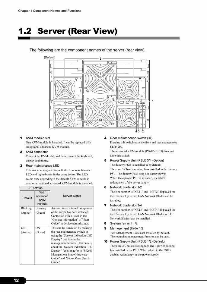
1.2 Server (Rear View)
The following are the component names of the server (rear view).
7
9
8
1
4 3 2
6
[Default]
10
5
1 KVM module slot
One KVM module is installed. It can be replaced with
an optional advanced KVM module.
2 KVM connector
Connect the KVM cable and then connect the keyboard,
display and mouse.
3 Rear maintenance LED
This works in conjunction with the front maintenance
LED and lights/blinks in the cases below. The LED
colors vary depending if the default KVM module is
used or an optional advanced KVM module is installed.
LED status
Server StatusDefault
With
advanced
KVM
module
Blinking
(Amber)
Blinking
(Green)
An error in an internal component
of the server has been detected.
Contact an office listed in the
"Contact Information" of "Start
Guide" or device administrator.
ON
(Amber)
ON
(Green)
This can be turned on by pressing
the rear maintenance switch or
using the "System Indication LED
Display" function in the
management terminal. For details
about the "System Indication LED
Display" function refer to "BX600
Management Blade Hardware
Guide" and "ServerView User’s
Guide".
4 Rear maintenance switch ( )
Pressing this switch turns the front and rear maintenance
LEDs ON.
The advanced KVM module (PG-KVB103) does not
have this switch.
5 Power Supply Unit (PSU) 3/4 (Option)
The dummy PSU is installed in by default.
There are 3 Chassis cooling fans installed in the dummy
PSU. The dummy PSU does not supply power.
When the optional PSU is installed, it enables
redundancy of the power supply.
6 Network blade slot 1/2
The slot number is "NET1" and "NET2" displayed on
the Chassis. Up to two LAN Network Blades can be
installed.
7 Network blade slot 3/4
The slot number is "NET3" and "NET4" displayed on
the Chassis. Up to two LAN Network Blades or FC
Network Blades, can be installed.
8 System fan unit 1/2
9 Management Blade 1/2
Two Management Blades are installed by default.
The redundant management function can be used.
10 Power Supply Unit (PSU) 1/2 (Default)
There are 2 Chassis cooling fans and 1 power cooling
fan installed in the PSU. When added to the PSU it
enables redundancy of the power supply.
ID
2
PRIMERGY BX600 S3 Blade Server System Unit Hardware Guide
28 29
14 15
DC ACFAN
21
18
17
2
3
16
2223
27
26
25
24
2019
* For device options not described in this manual, refer to the manuals supplied with each option.
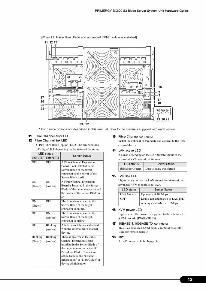
[When FC Pass-Thru Blade and advanced KVM module is installed]
11 12 13
11
12
Fibre Channel error LED
Fibre Channel link LED
FC Pass-Thru Blade (option) LED. The error and link
LEDs light/blink depending on the status of the server.
LED statusServer Status
Link LED Error LED
OFF OFF A Fibre Channel Expansion
Board is not installed in the
Server Blade of the target
connector or the power of the
Server Blade is off.
ON
(Green)
ON
(Amber)
A Fibre Channel Expansion
Board is installed in the Server
Blade of the target connector and
the power of the Server Blade is
on.
ON
(Green)
OFF The fibre channel card in the
Server Blade of the target
connector is online.
OFF ON
(Amber)
The fibre channel card in the
Server Blade of the target
connector is offline.
OFF Blinking
(Amber)
A link has not been established
with the external fibre channel
device.
Blinking
(Green)
Blinking
(Amber)
There is an error in the Fibre
Channel Expansion Board
installed in the Server Blade of
the target connector or the FC
Pass-Thru Blade. Contact an
office listed in the "Contact
Information" of "Start Guide" or
device administrator.
13 Fibre Channel connector
Install the optional SFP module and connect to the fibre
channel device.
14 LAN active LED
It blinks depending on the LAN transfer status of the
advanced KVM module as follows.
15 LAN link LED
Lights depending on the LAN connection status of the
advanced KVM module as follows.
16 KVM power LED
Lights when the power is supplied to the advanced
KVM module (PG-KVB103).
17 10BASE-T/100BASE-TX connector
This is an advanced KVM module (option) connector.
Used for remote console.
18 Inlet
An AC power cable is plugged in.
LED status Server Status
Blinking (Green) Data is being transferred
LED status Server Status
ON (Amber) Operating at 100Mbps
OFF Link is not established or LAN link
is being established at 10Mbps
13
1
Chapter 1 Component Names and Functions
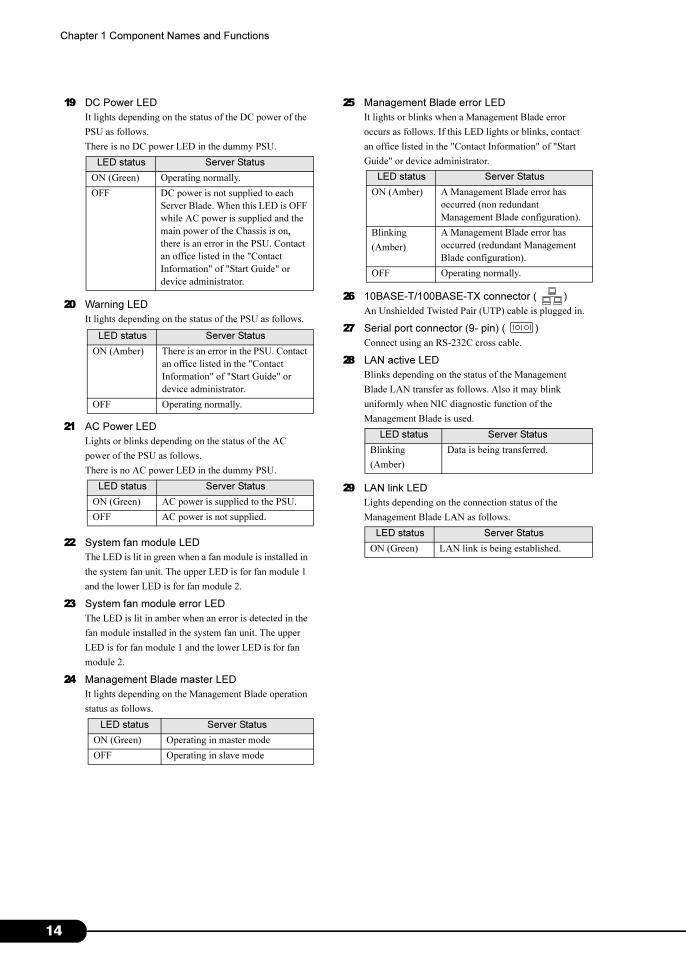
19 DC Power LED
It lights depending on the status of the DC power of the
PSU as follows.
There is no DC power LED in the dummy PSU.
20 Warning LED
It lights depending on the status of the PSU as follows.
21 AC Power LED
Lights or blinks depending on the status of the AC
power of the PSU as follows.
There is no AC power LED in the dummy PSU.
22 System fan module LED
The LED is lit in green when a fan module is installed in
the system fan unit. The upper LED is for fan module 1
and the lower LED is for fan module 2.
23 System fan module error LED
The LED is lit in amber when an error is detected in the
fan module installed in the system fan unit. The upper
LED is for fan module 1 and the lower LED is for fan
module 2.
24 Management Blade master LED
It lights depending on the Management Blade operation
status as follows.
LED status Server Status
ON (Green) Operating normally.
OFF DC power is not supplied to each
Server Blade. When this LED is OFF
while AC power is supplied and the
main power of the Chassis is on,
there is an error in the PSU. Contact
an office listed in the "Contact
Information" of "Start Guide" or
device administrator.
LED status Server Status
ON (Amber) There is an error in the PSU. Contact
an office listed in the "Contact
Information" of "Start Guide" or
device administrator.
OFF Operating normally.
LED status Server Status
ON (Green) AC power is supplied to the PSU.
OFF AC power is not supplied.
LED status Server Status
ON (Green) Operating in master mode
OFF Operating in slave mode
25 Management Blade error LED
It lights or blinks when a Management Blade error
occurs as follows. If this LED lights or blinks, contact
an office listed in the "Contact Information" of "Start
Guide" or device administrator.
26 10BASE-T/100BASE-TX connector ( )
An Unshielded Twisted Pair (UTP) cable is plugged in.
27 Serial port connector (9- pin) ( )
Connect using an RS-232C cross cable.
28 LAN active LED
Blinks depending on the status of the Management
Blade LAN transfer as follows. Also it may blink
uniformly when NIC diagnostic function of the
Management Blade is used.
29 LAN link LED
Lights depending on the connection status of the
Management Blade LAN as follows.
LED status Server Status
ON (Amber) A Management Blade error has
occurred (non redundant
Management Blade configuration).
Blinking
(Amber)
A Management Blade error has
occurred (redundant Management
Blade configuration).
OFF Operating normally.
LED status Server Status
Blinking
(Amber)
Data is being transferred.
LED status Server Status
ON (Green) LAN link is being established.
4

Chapter 2
Security
This chapter explains the security features that
are provided in order to protect the server
hardware and software from theft.
2.1 Hardware Security . . . . . . . . . . . . . . . . . . . . . . . . . . . . . . 16
2.2 Software Security . . . . . . . . . . . . . . . . . . . . . . . . . . . . . . 17
15
1
Chapter 2 Security
2.1 Hardware Security
Lock the rack door to protect the hardware in the rack from theft.
� Do not lose the rack key. If the key is lost, contact an office listed in the "Contact Information" of "Start
Guide".
� For instructions on opening the rack door, refer to "3.1 Opening the Rack Door" (�p.20).
� For details about other rack systems, refer to their respective manuals.
6
PRIMERGY BX600 S3 Blade Server System Unit Hardware Guide
2.2 Software Security
A password can be set to prevent unauthorized use of the server.
If a password is set, people who do not know the correct password cannot use the
server.
Perform password settings in the following blades.
For details about the settings of other optional devices, refer to each optional device manual.
• Management Blade
For details, refer to "BX600 Management Blade Hardware Guide".
• Switch Blade
For details, refer to each Switch Blade manual.
• Server Blade
For details, refer to "User's Guide".
17

1
Chapter 2 Security
8

Chapter 3
Standard Operations
This chapter explains such standard operations
as turning the server ON/OFF and inserting and
ejecting floppy disks.
3.1 Opening the Rack Door . . . . . . . . . . . . . . . . . . . . . . . . . . 20
3.2 Turning On the Server . . . . . . . . . . . . . . . . . . . . . . . . . . . 22
3.3 Turning Off the Server . . . . . . . . . . . . . . . . . . . . . . . . . . . 24
3.4 Inserting and Ejecting a Floppy Disk . . . . . . . . . . . . . . . . 26
3.5 CD/DVD Drive . . . . . . . . . . . . . . . . . . . . . . . . . . . . . . . . . 28
3.6 KVM Switch . . . . . . . . . . . . . . . . . . . . . . . . . . . . . . . . . . 30
19
2
Chapter 3 Standard Operations
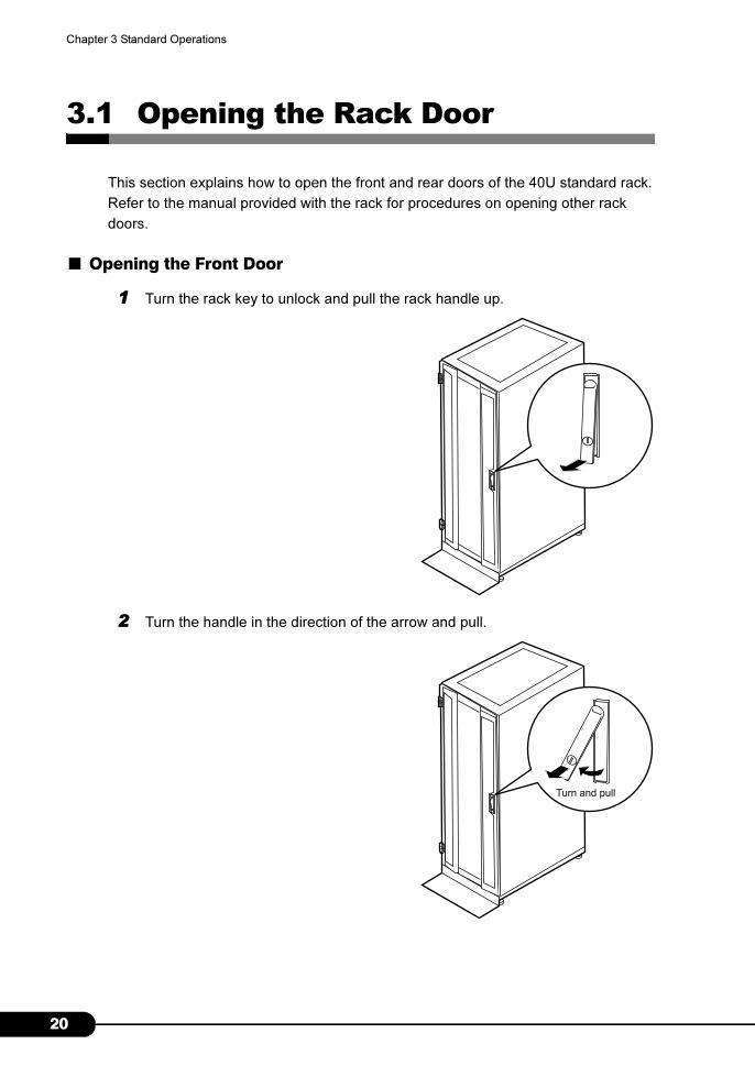
3.1 Opening the Rack Door
This section explains how to open the front and rear doors of the 40U standard rack.
Refer to the manual provided with the rack for procedures on opening other rack
doors.
■ Opening the Front Door
1 Turn the rack key to unlock and pull the rack handle up.
2 Turn the handle in the direction of the arrow and pull.
Turn and pull
0
PRIMERGY BX600 S3 Blade Server System Unit Hardware Guide
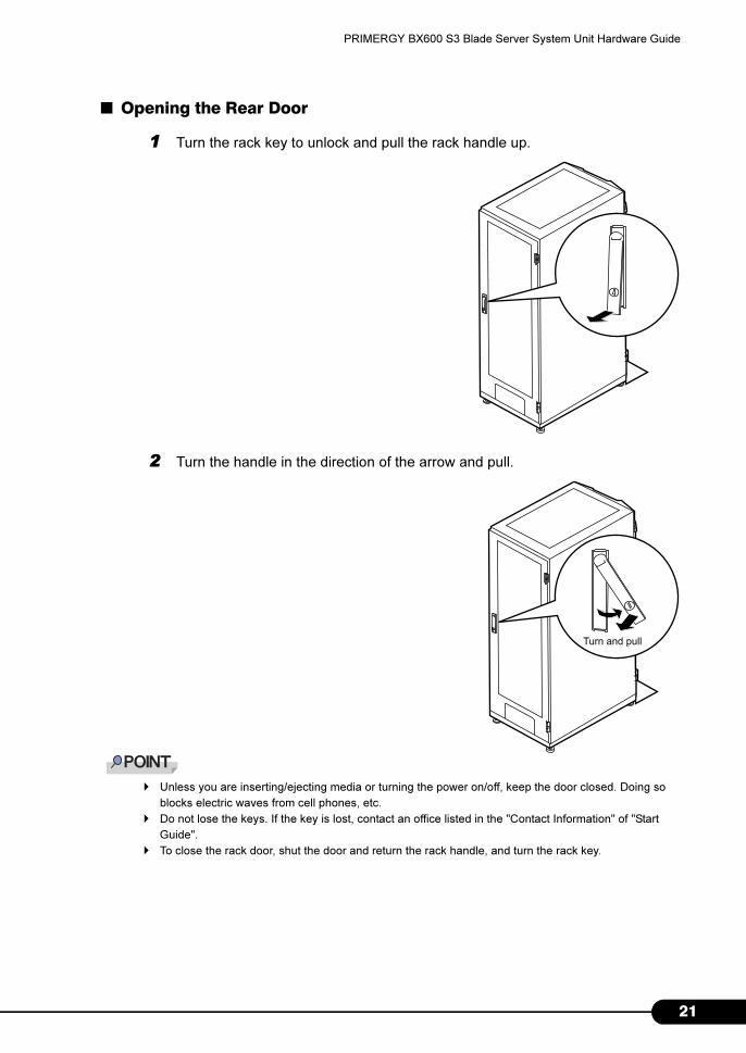
■ Opening the Rear Door
1 Turn the rack key to unlock and pull the rack handle up.
2 Turn the handle in the direction of the arrow and pull.
� Unless you are inserting/ejecting media or turning the power on/off, keep the door closed. Doing so
blocks electric waves from cell phones, etc.
� Do not lose the keys. If the key is lost, contact an office listed in the "Contact Information" of "Start
Guide".
� To close the rack door, shut the door and return the rack handle, and turn the rack key.
Turn and pull
21
2
Chapter 3 Standard Operations
3.2 Turning On the Server
1 Open the rack door.
�"3.1 Opening the Rack Door" (p.20)
2 Power on the display and peripheral devices.
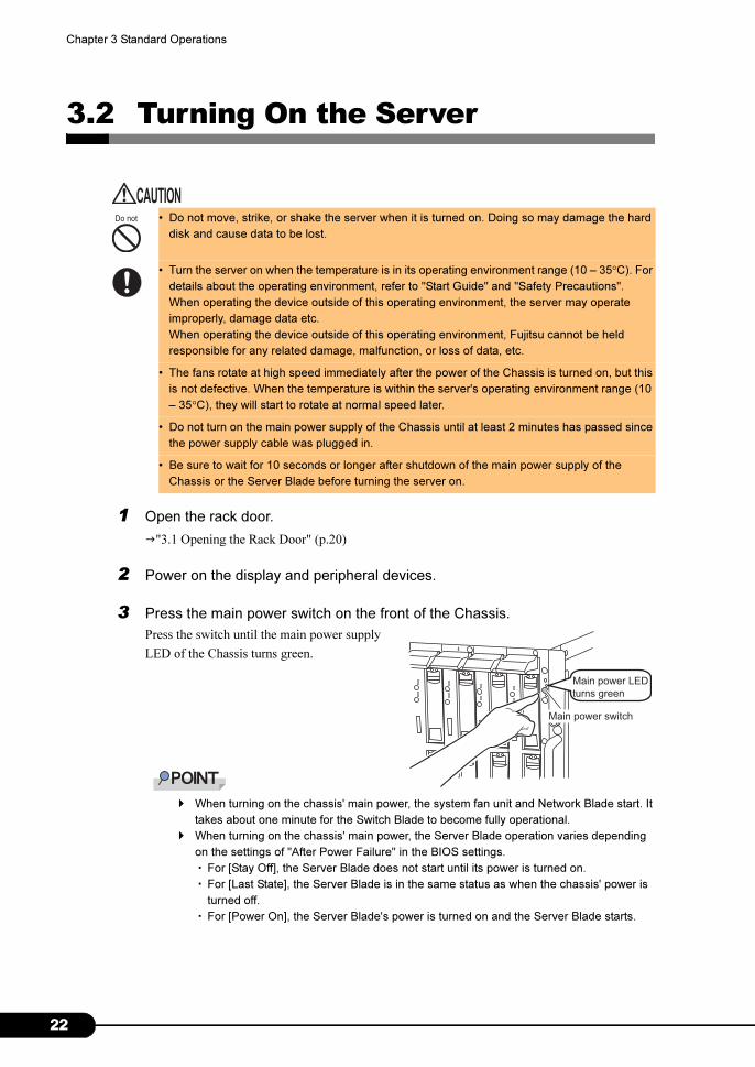
3 Press the main power switch on the front of the Chassis.
Press the switch until the main power supply
LED of the Chassis turns green.
� When turning on the chassis' main power, the system fan unit and Network Blade start. It
takes about one minute for the Switch Blade to become fully operational.
� When turning on the chassis' main power, the Server Blade operation varies depending
on the settings of "After Power Failure" in the BIOS settings.
・For [Stay Off], the Server Blade does not start until its power is turned on.
・For [Last State], the Server Blade is in the same status as when the chassis' power is
turned off.
・For [Power On], the Server Blade's power is turned on and the Server Blade starts.
• Do not move, strike, or shake the server when it is turned on. Doing so may damage the hard
disk and cause data to be lost.
• Turn the server on when the temperature is in its operating environment range (10 – 35°C). For
details about the operating environment, refer to "Start Guide" and "Safety Precautions".
When operating the device outside of this operating environment, the server may operate
improperly, damage data etc.
When operating the device outside of this operating environment, Fujitsu cannot be held
responsible for any related damage, malfunction, or loss of data, etc.
• The fans rotate at high speed immediately after the power of the Chassis is turned on, but this
is not defective. When the temperature is within the server's operating environment range (10
– 35°C), they will start to rotate at normal speed later.
• Do not turn on the main power supply of the Chassis until at least 2 minutes has passed since
the power supply cable was plugged in.
• Be sure to wait for 10 seconds or longer after shutdown of the main power supply of the
Chassis or the Server Blade before turning the server on.
Main power LED
turns green
Main power switch
2

PRIMERGY BX600 S3 Blade Server System Unit Hardware Guide
� When turning on the chassis' main power, the Storage Blade works in conjunction with
connected Server Blade power operations. Normally, the power of the Storage Blade and
Server Blade are turned on at the same time. The Server Blade's power may turn on
approximately 15 seconds after the Storage Blade's power turns on. This happens
because Sever Blade initialization takes time. This does not mean there is a failure.
4 Press the Server blade power switch.
Server Blade is activated.
When the power is turned on, the Server Blade
performs Power On Self Tests (POST).
If any abnormalities are detected by POST, error
messages are displayed.
→ "User's Guide 9.2 Troubleshooting"
� When Server Blade is set to network activation (PXE), after turning on the main power supply of the
Chassis, wait at least one minute before turning on the power of the Server Blade.
In that time, the Switch Blade is not completely activated or the reconfiguration of the network is not
complete.
Server blade
power LED
turns green
Server blade power switch
23
2
Chapter 3 Standard Operations
3.3 Turning Off the Server
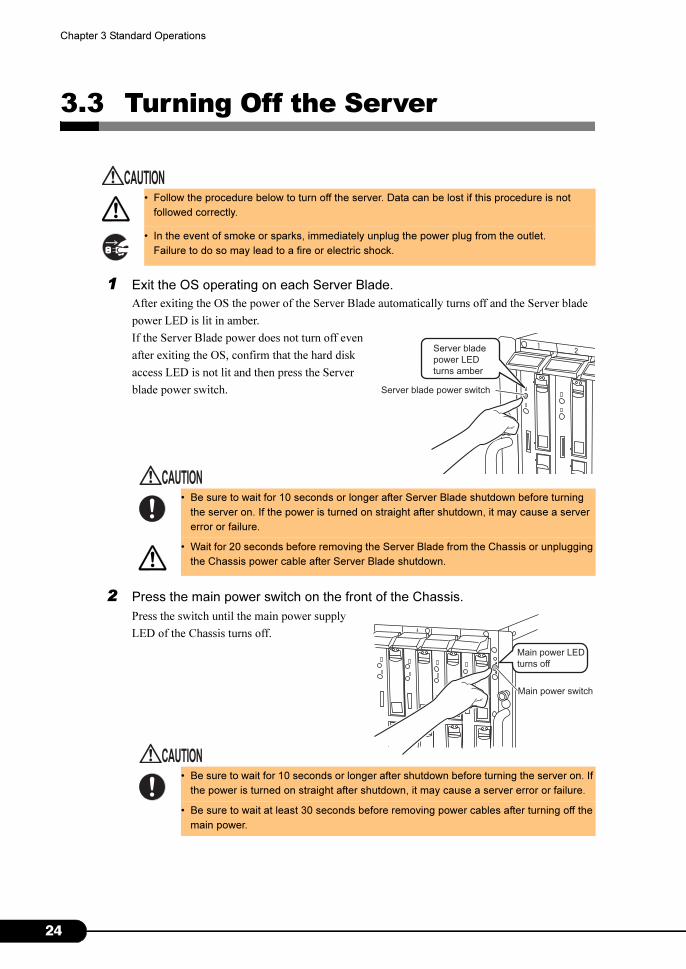
1 Exit the OS operating on each Server Blade.
After exiting the OS the power of the Server Blade automatically turns off and the Server blade
power LED is lit in amber.
If the Server Blade power does not turn off even
after exiting the OS, confirm that the hard disk
access LED is not lit and then press the Server
blade power switch.
2 Press the main power switch on the front of the Chassis.
Press the switch until the main power supply
LED of the Chassis turns off.
• Follow the procedure below to turn off the server. Data can be lost if this procedure is not
followed correctly.
• In the event of smoke or sparks, immediately unplug the power plug from the outlet.
Failure to do so may lead to a fire or electric shock.
• Be sure to wait for 10 seconds or longer after Server Blade shutdown before turning
the server on. If the power is turned on straight after shutdown, it may cause a server
error or failure.
• Wait for 20 seconds before removing the Server Blade from the Chassis or unplugging
the Chassis power cable after Server Blade shutdown.
• Be sure to wait for 10 seconds or longer after shutdown before turning the server on. If
the power is turned on straight after shutdown, it may cause a server error or failure.
• Be sure to wait at least 30 seconds before removing power cables after turning off the
main power.
Server blade
power LED
turns amber
Server blade power switch
Main power LED
turns off
Main power switch
4
PRIMERGY BX600 S3 Blade Server System Unit Hardware Guide
3 Power off the display and peripheral devices.
� The server can be remotely turned on/off from the management terminal using Management Blade.
→"BX600 Management Blade Hardware Guide"
� The power supply of each Server Blade can be turned off remotely from the management terminal
using the attached ServerView software. For details, refer to "ServerView User’s Guide 3.2 Monitoring
Servers".
■ Notes on power supply operations (for Windows)
The following modes can be specified for the Server Blade power switch using the OS settings.
• For Windows Server 2003 or Windows Server 2008
"Do Nothing", "Prompt Input" (only for Windows Server 2003), "Standby", "Hibernation", or "Shut
down" (normally, "Shut down" is specified).
• For Windows 2000 Server
"Standby", "Hibernation", "Power off" (normally "Power off" is specified).
On this Server Blade, functions corresponding to "Standby" and "Hibernation" are supported as BIOS
and hardware functions. However, some drivers and software installed in the Server Blade do not
support these functions. For this reason, functions corresponding to "Standby" and "Hibernation" are
unavailable on this server.
When the operating mode is set to "Standby" or "Hibernation", the system may operate improperly or
hard disk data may be corrupted.
For details about operating mode settings, refer to the OS manual.
� For Windows Server 2003, by changing the power switch operating mode "Do Nothing", or "Prompt
Input", prevents the OS being shutdown by mistakenly pressing the power switch during operation.
25
2
Chapter 3 Standard Operations
3.4 Inserting and Ejecting a Floppy Disk
Inserting and ejecting a floppy disk is described below.
3.4.1 Cautions
Note the following points when handling floppy disks.
• Do not expose the floppy disk to any fluids.
• Do not open the shutter of the floppy disk and touch the disk surface.
• Do not bend the floppy disk or place heavy objects on it.
• Do not expose the floppy disk to strong magnetic fields.
• Do not drop the floppy disk on hard surfaces.
• Do not store the disk in extremely hot or cold conditions.
• Do not put layers of labels on the floppy disk.
• Keep the floppy disk away from condensation or water droplets.
6

PRIMERGY BX600 S3 Blade Server System Unit Hardware Guide
3.4.2 Inserting and Ejecting a Floppy Disk
■ Inserting the Floppy Disk
1 Use the display/USB expansion cable and connect a floppy disk drive to the
Server Blade.
→"Start Guide"
2 Insert the floppy disk drive from the side with the shutter.
After clicking into place, the floppy disk
eject button pops out.
■ Ejecting the Floppy Disk
Make sure that the floppy disk access LED is off. Press the floppy disk eject button.
The floppy disk is ejected.
• Do not eject the floppy disk while the floppy disk access LED is on. The data stored on the
floppy disk may be damaged.
Floppy disk eject button
Shutter
Face the label up
OFF
Floppy disk access LED
Floppy disk eject button
27
2
Chapter 3 Standard Operations
3.5 CD/DVD Drive
This manual describes the points to note when handling a CD/DVD drive or CD/DVD.
For details about inserting/ejecting the CD/DVD, refer to the manual supplied with the
CD/DVD drive.
� This server does not support CD-R/RW write.
3.5.1 Cautions
Note the following points to prevent failure.
■ Drive
• High humidity and airborne dust levels are to be avoided. Electric shocks and/or server failures may
be caused by liquids such as water, or metallic items, such as paper clips, entering a drive.
• Shocks and vibrations are also to be avoided.
• Do not insert any objects other than the specified CDs/DVDs.
• Do not pull on, press hard, or otherwise handle the CD/DVD tray roughly.
• Do not disassemble the CD/DVD drive.
• Before use, clean the CD/DVD tray using a soft, dry cloth.
• As a precaution, remove discs from the CD/DVD drive when the drive is not to be used for a long
time. Keep the CD/DVD tray closed to prevent foreign matter, such as dust, from entering the CD/
DVD drive.
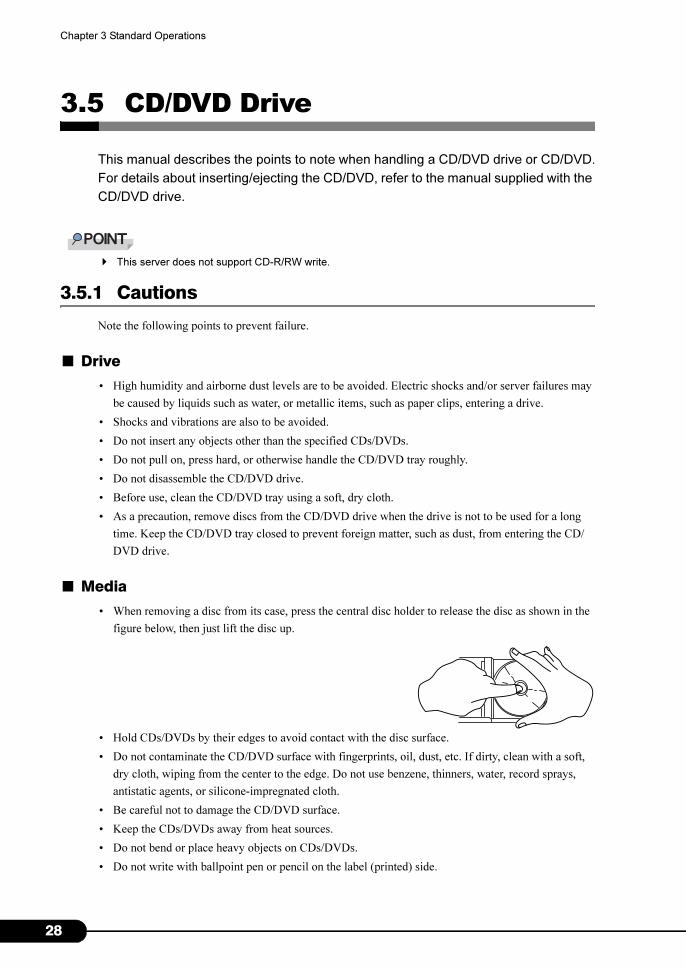
■ Media
• When removing a disc from its case, press the central disc holder to release the disc as shown in the
figure below, then just lift the disc up.
• Hold CDs/DVDs by their edges to avoid contact with the disc surface.
• Do not contaminate the CD/DVD surface with fingerprints, oil, dust, etc. If dirty, clean with a soft,
dry cloth, wiping from the center to the edge. Do not use benzene, thinners, water, record sprays,
antistatic agents, or silicone-impregnated cloth.
• Be careful not to damage the CD/DVD surface.
• Keep the CDs/DVDs away from heat sources.
• Do not bend or place heavy objects on CDs/DVDs.
• Do not write with ballpoint pen or pencil on the label (printed) side.
8

PRIMERGY BX600 S3 Blade Server System Unit Hardware Guide
• Do not attach stickers or similar to the label side. Doing so may cause rotational eccentricity and
abnormal vibrations.
• When a CD/DVD is moved from a cold place to a warm place, moisture condensation on the CD/
DVD surface can cause data read errors. In this case, wipe the CD/DVD with a soft, dry cloth then let
it air dry. Do not dry the CD/DVD using devices such as a hair dryer.
• To avoid dust, damage, and deformation, keep the CD/DVD in its case whenever it is not in use.
• Do not store CDs/DVDs at high temperatures. Areas exposed to prolonged direct sunlight or near
heating appliances are to be avoided.
29

3
Chapter 3 Standard Operations
3.6 KVM Switch
The inputs/outputs of the keyboard/display/mouse (KVM) of various Server Blades
are connected to the KVM connector of the KVM module or advanced KVM module
installed in the Chassis using the KVM switch in the Chassis.
Perform KVM switching operations using one of the following methods.
• Press the KVM select switch of the Server Blade.
• Use the Management Blade from the management terminal and perform switching operations.
→ "BX600 Management Blade Hardware Guide"
� OSCAR operation is possible when using an advanced KVM module (PG-KVB103).
For details, refer to "6.4.1 OSCAR" (�p.82)
� When KVM switching operations are performed consecutively, confirm that the selected Server
Blade has completely switched, by checking the KVM selected LED or the display screen, before
performing the next operation.
0
Chapter 4
Installing Options
This chapter explains how to install and remove
various options to the Chassis.
4.1 Options . . . . . . . . . . . . . . . . . . . . . . . . . . . . . . . . . . . . . . 32
4.2 Installing Server Blades/Storage Blades . . . . . . . . . . . . . . 34
4.3 Installing Network Blades . . . . . . . . . . . . . . . . . . . . . . . . 42
4.4 Installing the PSU . . . . . . . . . . . . . . . . . . . . . . . . . . . . . . 50
4.5 Installing Advanced KVM Module . . . . . . . . . . . . . . . . . . . 54
4.6 Replacing the Management Blade . . . . . . . . . . . . . . . . . . 58
4.7 Replacing the System Fan Unit . . . . . . . . . . . . . . . . . . . . 59
31

3
Chapter 4 Installing Options
4.1 Options
It is possible to install the following blades and PSUs to the Chassis.
For details about device options not shown in this manual, refer to each option
manual.
• Do not disassemble the PSU. Doing so may cause electric shock.
• Do not install unauthorized third party internal options. Doing so may cause a device failure,
fire, or electric shock.
• Do not damage or modify internal cables or devices. Doing so may cause a device failure, fire,
or electric shock.
[Front] Server Blade/Storage Blade
Switch Blade/GbE Pass-Thru Blade/FC Pass-Thru Blade, etc.
PSU
Switch Blade/GbE Pass-Thru Blade, etc.[Rear]
2

PRIMERGY BX600 S3 Blade Server System Unit Hardware Guide
• Before handling options, first touch a metal part of the Chassis to discharge static electricity.
• Do not touch the circuitry on boards. Hold the brackets or the edges of the circuit boards.
• If devices are installed or removed other than by the methods outlined in this chapter, the
warranty will be invalidated.
33

3
Chapter 4 Installing Options
4.2 Installing Server Blades/Storage Blades
This section explains how to install/remove Server Blades and Storage Blades.
For this server, even when the power supply of the Chassis is turned on, it is possible
to install/remove (hot-swap/hot-plug) Server Blades.
For details about a Server Blade, refer to each Server Blade's "User's Guide", and for
details about a Storage Blade, refer to "SX650 Storage Blade Hardware
Guide".
4.2.1 Before Installing
■ Notes when installing and removing
Server Blades/Storage Blades can be installed/removed when the main power of the Chassis is turned
on. In this case note the following points.
■ Installable Server Blades/Storage Blades
The following Server Blades or Storage Blades can be installed in the Chassis.
• BX620 S3 Server Blade
• BX620 S4 Server Blade
• SX650 Storage Blade
• Always turn off the power of the Server Blade.
�"3.3 Turning Off the Server" (p.24)
• Check that the system fan unit is operating correctly before installing or removing the blade
server. If it is broken, the blade server cannot be installed/removed during operation.
• Because the heat sink area of the Server Blade reaches high temperatures, do not touch it
directly after removal.
• Be careful not to pinch fingers or clothes. This may cause injury.
• When removing the Server Blade/Storage Blade/dummy Server Blade, do not insert your
hand into the Server Blade slot. Doing so may cause electric shock.
4
PRIMERGY BX600 S3 Blade Server System Unit Hardware Guide
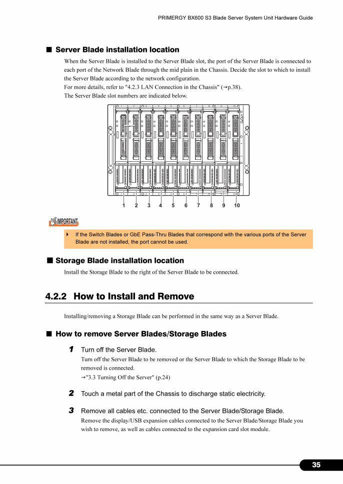
■ Server Blade installation location
When the Server Blade is installed to the Server Blade slot, the port of the Server Blade is connected to
each port of the Network Blade through the mid plain in the Chassis. Decide the slot to which to install
the Server Blade according to the network configuration.
For more details, refer to "4.2.3 LAN Connection in the Chassis" (�p.38).
The Server Blade slot numbers are indicated below.
■ Storage Blade installation location
Install the Storage Blade to the right of the Server Blade to be connected.
4.2.2 How to Install and Remove
Installing/removing a Storage Blade can be performed in the same way as a Server Blade.
■ How to remove Server Blades/Storage Blades
1 Turn off the Server Blade.
Turn off the Server Blade to be removed or the Server Blade to which the Storage Blade to be
removed is connected.
�"3.3 Turning Off the Server" (p.24)
2 Touch a metal part of the Chassis to discharge static electricity.
3 Remove all cables etc. connected to the Server Blade/Storage Blade.
Remove the display/USB expansion cables connected to the Server Blade/Storage Blade you
wish to remove, as well as cables connected to the expansion card slot module.
� If the Switch Blades or GbE Pass-Thru Blades that correspond with the various ports of the Server
Blade are not installed, the port cannot be used.
1 2 3 4 5 6 7 8 9 10
35
3
Chapter 4 Installing Options
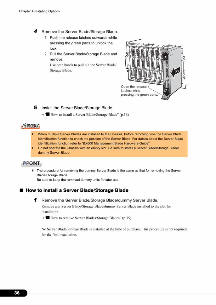
4 Remove the Server Blade/Storage Blade.
1. Push the release latches outwards while
pressing the green parts to unlock the
lock.
2. Pull the Server Blade/Storage Blade and
remove.
Use both hands to pull out the Server Blade/
Storage Blade.
5 Install the Server Blade/Storage Blade.
�"■ How to install a Server Blade/Storage Blade" (p.36)
� The procedure for removing the dummy Server Blade is the same as that for removing the Server
Blade/Storage Blade.
Be sure to keep the removed dummy units for later use.
■ How to install a Server Blade/Storage Blade
1 Remove the Server Blade/Storage Blade/dummy Server Blade.
Remove any Server Blade/Storage Blade/dummy Server Blade installed to the slot for
installation.
�"■ How to remove Server Blades/Storage Blades" (p.35)
No Server Blade/Storage Blade is installed at the time of purchase. This procedure is not required
for the first installation.
� When multiple Server Blades are installed to the Chassis, before removing, use the Server Blade
identification function to check the position of the Server Blade. For details about the Server Blade
identification function refer to "BX600 Management Blade Hardware Guide".
� Do not operate the Chassis with an empty slot. Be sure to install a Server Blade/Storage Blade/
dummy Server Blade.
(2)
(1)
(1)
Open the release
latches while
pressing the green parts.
6

PRIMERGY BX600 S3 Blade Server System Unit Hardware Guide
2 Install the Server Blade/Storage Blade.
1. Open the release latches and insert the Server Blade/Storage Blade until it stops.
2. When inserted, close the release
latches to complete insertion.
� The procedure for installing the dummy Server Blade is the same as that for installing the
Server Blade/Storage Blade.
3 Connect cables when using the expansion card slot module for the Server
Blade.
� In order to move the cables connected to the expansion card slot of the Server Blade out
of the way, create space in the lower part of the Chassis and pull towards the rear of the
server.
� To operate the Storage Blade, the Storage Blade must be connected to the Server Blade
with the SAS cable. For connection, refer to "SX650 Storage Blade Hardware Guide".
� Before installing the Server Blade/Storage Blade, check there is no dust in the blade
connector.
� Before closing the release latches, make sure the Server Blade/Storage Blade is
inserted completely to the slot.
(2)
(1)
(2)
Release latches
37

3
Chapter 4 Installing Options
4.2.3 LAN Connection in the Chassis
This section explains the LAN connection in the Chassis for Server Blades and LAN Network Blades.
The LAN ports for Server Blades and LAN Network Blades are connected as follows in the Chassis.
Decide the slot to which to install the Server Blade or LAN Network Blade according to the network
configuration.
� When installing a LAN Network Blade to the Network Blade slot 3 or 4, the LAN port can be used by
installing the LAN Expansion Board to the Server Blade. For details, refer to the LAN Expansion Board
manual.
■ For combinations except for that of BX620 S4 Server Blade and PG-SW107
• Network blade slot 1/3 (NET1/NET3)
*: For Network Blade slot 1, connect to the onboard LAN. For Network Blade slot 3, connect to
LAN expansion board.
• Network Blade slot 2/4 (NET2/NET4)
*: For Network Blade slot 2, connect to the onboard LAN. For Network Blade slot 4, connect to
LAN expansion board.
Network blade
port number
Server blade
Slot number Port number (*)
1 1
1
2 2
3 3
4 4
5 5
6 6
7 7
8 8
9 9
10 10
Network blade
port number
Server blade
Slot number Port number (*)
1 1
2
2 2
3 3
4 4
5 5
6 6
7 7
8 8
9 9
10 10
8
PRIMERGY BX600 S3 Blade Server System Unit Hardware Guide
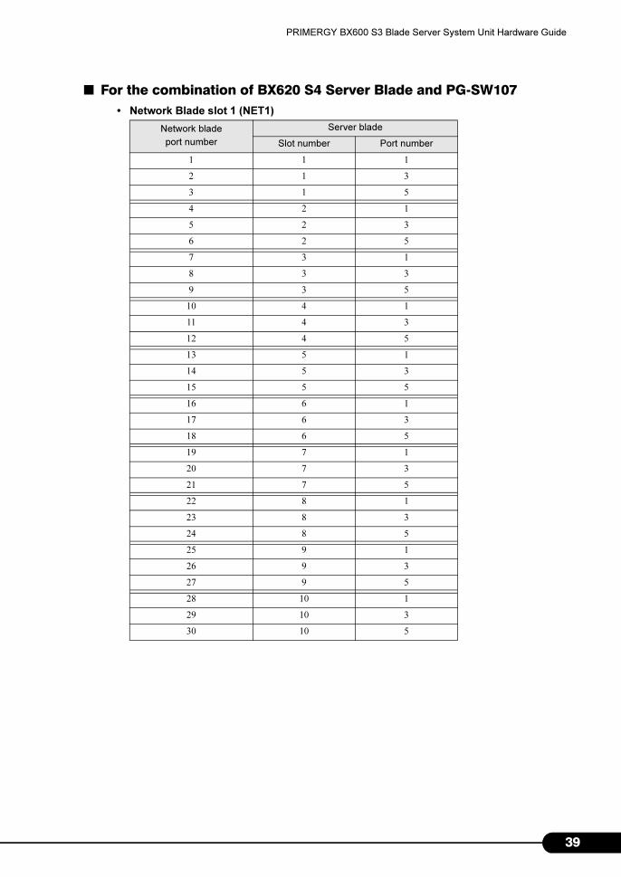
■ For the combination of BX620 S4 Server Blade and PG-SW107
• Network Blade slot 1 (NET1)
Network blade
port number
Server blade
Slot number Port number
1 1 1
2 1 3
3 1 5
4 2 1
5 2 3
6 2 5
7 3 1
8 3 3
9 3 5
10 4 1
11 4 3
12 4 5
13 5 1
14 5 3
15 5 5
16 6 1
17 6 3
18 6 5
19 7 1
20 7 3
21 7 5
22 8 1
23 8 3
24 8 5
25 9 1
26 9 3
27 9 5
28 10 1
29 10 3
30 10 5
39
4
Chapter 4 Installing Options
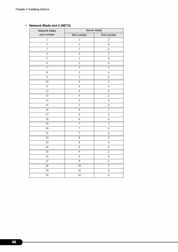
• Network Blade slot 2 (NET2)
Network blade
port number
Server blade
Slot number Port number
1 1 2
2 1 4
3 1 6
4 2 2
5 2 4
6 2 6
7 3 2
8 3 4
9 3 6
10 4 2
11 4 4
12 4 6
13 5 2
14 5 4
15 5 6
16 6 2
17 6 4
18 6 6
19 7 2
20 7 4
21 7 6
22 8 2
23 8 4
24 8 6
25 9 2
26 9 4
27 9 6
28 10 2
29 10 4
30 10 6
0
PRIMERGY BX600 S3 Blade Server System Unit Hardware Guide
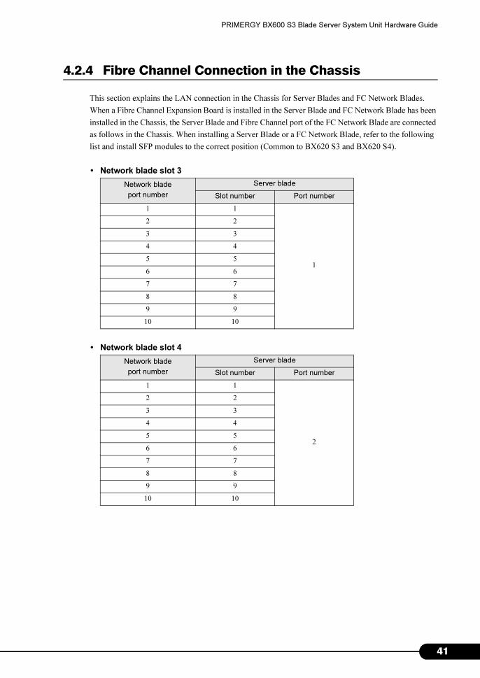
4.2.4 Fibre Channel Connection in the Chassis
This section explains the LAN connection in the Chassis for Server Blades and FC Network Blades.
When a Fibre Channel Expansion Board is installed in the Server Blade and FC Network Blade has been
installed in the Chassis, the Server Blade and Fibre Channel port of the FC Network Blade are connected
as follows in the Chassis. When installing a Server Blade or a FC Network Blade, refer to the following
list and install SFP modules to the correct position (Common to BX620 S3 and BX620 S4).
• Network blade slot 3
• Network blade slot 4
Network blade
port number
Server blade
Slot number Port number
1 1
1
2 2
3 3
4 4
5 5
6 6
7 7
8 8
9 9
10 10
Network blade
port number
Server blade
Slot number Port number
1 1
2
2 2
3 3
4 4
5 5
6 6
7 7
8 8
9 9
10 10
41
4
Chapter 4 Installing Options
4.3 Installing Network Blades
This section explains how to install/remove Network Blades. For this server, even
when the power supply of the Chassis is turned on it is possible to install/remove
(hot-swap/hot-plug) Network Blades.
For Network Blades not shown in this manual, refer to each Network Blade manual.
4.3.1 Installing/Removing LAN Network Blades
This section explains how to install/remove LAN Network Blades.
For more details about the various blades, refer to the Network Blade manuals.
■ Before installing
● Notes when installing and removing
Network Blades can be installed/removed when the main power of the Chassis is turned on.
• When removing the LAN Network Blades or dummy Switch Blade, do not insert your hand
into the Network Blade slot. Doing so may cause electric shock.
• When installing a LAN Network Blade, make sure that it is inserted completely in the slot
before setting the handle.
� If the Server Blade connected to a LAN Network Blade is operating, disconnecting the LAN Network
Blade will cause LAN connection to be lost.
2

PRIMERGY BX600 S3 Blade Server System Unit Hardware Guide
● LAN Network Blade installation location
● Available LAN Network Blade
The following shows the type of LAN Network Blade used for this Chassis.
� Included optional LAN Network Blade
Before installing each blade, refer to the LAN Network Blade manual and check the included options.
Product name Model
Switch Blade PG-SW104
Switch Blade PG-SW105
Cisco Catalyst Blade Switch 3040 PG-SW106
Switch Blade PG-SW107
GbE Pass-Thru Blade PG-LNB102
[Rear of the chassis]
Network blade
slot 2
Network blade
slot 4
Network blade
slot 1
Network blade
slot 3
*: PRIMERGY BX600 Switch Blade (1Gbps) (PG-SW107) can only be installed in slot 1 and 2.
(*) (*)
43
4
Chapter 4 Installing Options
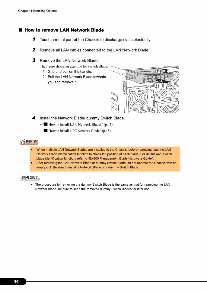
■ How to remove LAN Network Blade
1 Touch a metal part of the Chassis to discharge static electricity.
2 Remove all LAN cables connected to the LAN Network Blade.
3 Remove the LAN Network Blade.
The figure shows an example for Switch Blade.
1. Grip and pull on the handle.
2. Pull the LAN Network Blade towards
you and remove it.
4 Install the Network Blade/ dummy Switch Blade.
�"■ How to install LAN Network Blades" (p.45)
�"■ How to install a FC Network Blade" (p.48)
� The procedure for removing the dummy Switch Blade is the same as that for removing the LAN
Network Blade. Be sure to keep the removed dummy Switch Blades for later use.
� When multiple LAN Network Blades are installed to the Chassis, before removing, use the LAN
Network Blade identification function to check the position of each blade. For details about each
blade identification function, refer to "BX600 Management Blade Hardware Guide".
� After removing the LAN Network Blade or dummy Switch Blade, do not operate the Chassis with an
empty slot. Be sure to install a Network Blade or a dummy Switch Blade.
(2)
Handle
(1)
4

PRIMERGY BX600 S3 Blade Server System Unit Hardware Guide
■ How to install LAN Network Blades
1 Touch a metal part of the Chassis to discharge static electricity.
2 Remove the Network Blade/ dummy Switch Blade.
Remove any blade installed to the slot for installation.
�"■ How to remove LAN Network Blade" (p.44)
�"■ How to remove FC Network Blades" (p.47)
3 Install LAN Network Blades.
The figure shows an example using Switch
Blade.
1. Insert the LAN Network Blade.
2. Set the handle.
� The procedure for installing the dummy Switch Blade is the same as that for installing the
LAN Network Blade.
4 Install a LAN cable to LAN Network Blades.
� Before installing a LAN Network Blade, check there is no dust in the blade connector.
� When installing a LAN Network Blade, it is necessary to press the Switch Blade in with
your finger after inserting it using the handle.
(1)
Handle
(2)
45

4
Chapter 4 Installing Options
4.3.2 Installing/Removing FC Network Blades
This section explains how to install/remove FC Network Blades.
■ Before installing
● Notes when installing and removing
Each Network Blade can be installed/removed when the main power of the Chassis is turned on.
● FC Network Blade installation location
● Available FC Network Blade
The following shows the type of FC Network Blade used for this Chassis.
� Included FC Network Blade options
Before installing the FC Pass-Thru Blade, refer to the following and check the included options.
• FC Switch Blade: FC Switch Blade manual
• FC Pass-Thru Blade:"6.1.2 FC Pass-Thru Blade Specifications" (�p.67)
• When removing the FC Network Blades or dummy Switch Blade, do not insert your hand into
the Network Blade slot. Doing so may cause electric shock.
• Before setting the handle, make sure that the FC Network Blade is inserted completely to the
slot.
Product name Model
FC Switch Blade PG-FCS103
FC Pass-Thru Blade PG-FCB103
[Rear of the chassis]
Network bladeslot 4
Network bladeslot 3
6
PRIMERGY BX600 S3 Blade Server System Unit Hardware Guide
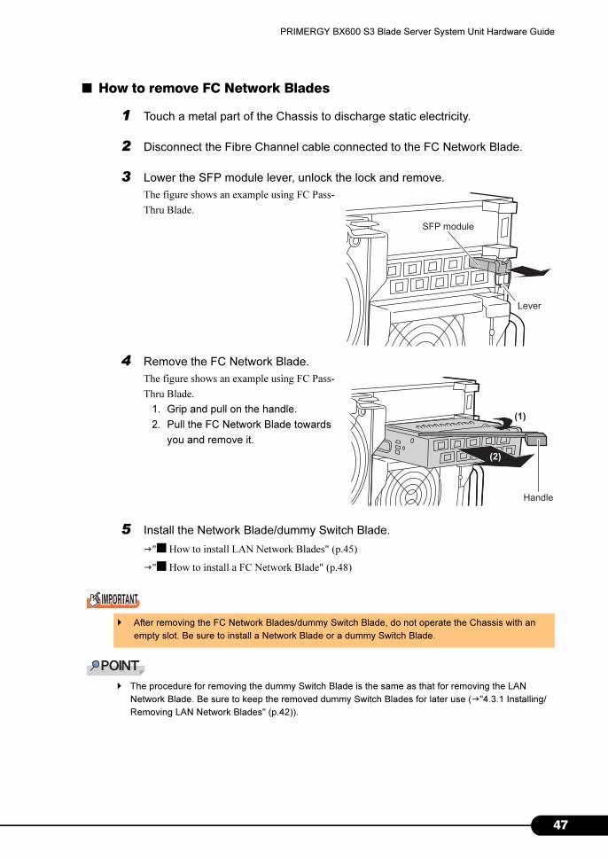
■ How to remove FC Network Blades
1 Touch a metal part of the Chassis to discharge static electricity.
2 Disconnect the Fibre Channel cable connected to the FC Network Blade.
3 Lower the SFP module lever, unlock the lock and remove.
The figure shows an example using FC Pass-
Thru Blade.
4 Remove the FC Network Blade.
The figure shows an example using FC Pass-
Thru Blade.
1. Grip and pull on the handle.
2. Pull the FC Network Blade towards
you and remove it.
5 Install the Network Blade/dummy Switch Blade.
�"■ How to install LAN Network Blades" (p.45)
�"■ How to install a FC Network Blade" (p.48)
� The procedure for removing the dummy Switch Blade is the same as that for removing the LAN
Network Blade. Be sure to keep the removed dummy Switch Blades for later use (�"4.3.1 Installing/
Removing LAN Network Blades" (p.42)).
� After removing the FC Network Blades/dummy Switch Blade, do not operate the Chassis with an
empty slot. Be sure to install a Network Blade or a dummy Switch Blade.
SFP module
Lever
(1)
(2)
Handle
47

4
Chapter 4 Installing Options
■ How to install a FC Network Blade
1 Touch a metal part of the Chassis to discharge static electricity.
2 Remove the Network Blade/ dummy Switch Blade.
Remove any blade installed to the slot for installation.
�"■ How to remove LAN Network Blade" (p.44)
�"■ How to remove FC Network Blades" (p.47)
3 Install a FC Network Blade.
The figure shows an example using FC Pass-Thru Blade.
1. Insert the FC Network Blade.
2. Set the handle.
� The procedure for installing the dummy Switch Blade is the same as that for installing the
LAN Network Blade (�"4.3.1 Installing/Removing LAN Network Blades" (p.42)).
� Before installing the FC Network Blade, check there is no dust in the blade connector.
� When installing a FC Network Blade, it is necessary to press the FC Network Blade in
with your finger after inserting it with a handle.
(2)
(1)
Handle
8
PRIMERGY BX600 S3 Blade Server System Unit Hardware Guide
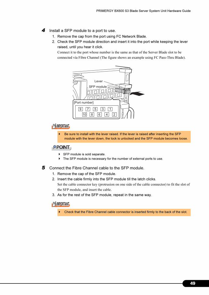
4 Install a SFP module to a port to use.
1. Remove the cap from the port using FC Network Blade.
2. Check the SFP module direction and insert it into the port while keeping the lever
raised, until you hear it click.
Connect it to the port whose number is the same as that of the Server Blade slot to be
connected via Fibre Channel (The figure shows an example using FC Pass-Thru Blade).
� SFP module is sold separate.
� The SFP module is necessary for the number of external ports to use.
5 Connect the Fibre Channel cable to the SFP module.
1. Remove the cap of the SFP module.
2. Insert the cable firmly into the SFP module till the latch clicks.
Set the cable connector key (protrusion on one side of the cable connector) to fit the slot of
the SFP module, and insert the cable.
3. As for the rest of the SFP module, repeat in the same way.
� Be sure to install with the lever raised. If the lever is raised after inserting the SFP
module with the lever down, the lock is unlocked and the SFP module becomes loose.
� Check that the Fibre Channel cable connector is inserted firmly to the back of the slot.
SFP module
[Port number]
13579
246810
Lever
49
5
Chapter 4 Installing Options
4.4 Installing the PSU
In this Chassis, two PSUs are installed by default and a maximum of four can be
installed.
Adding PSUs enables redundancy of the power supply. Install the PSUs in pairs and
connect power cables to all the PSUs.
This section explains points to note when expanding the PSUs, how to install/remove
and replace the PSU.
� Have broken PSUs replaced as soon as possible.
� Up to 10 Server Blades can be installed using the two default PSUs. The number of Server Blades that
can be installed is limited by the Server Blade configuration, and the type and number of installed PSU.
To configure redundant power supply, add PSUs.
4.4.1 Before Installing the PSU
Notes when redundancy of the power supply is enabled.
■ Conditions for the power redundancy function
To enable redundancy of the power supply, it is necessary to add two PSUs.
■ Available PSU
The following shows PSU types used for this Chassis.
• Do not disassemble the PSU. Doing so may cause electric shock or fire.
• When installing or removing PSUs from the server, be sure to turn off the server and all the
connected devices as well as unplugging all the power cables. Failure to do so may cause
electric shock (�"3.3 Turning Off the Server" (p.24)).
If a broken PSU is replaced when the redundant power supply is installed, the PSU can be
replaced even if the power is turned on.
• When removing the PSU or dummy PSU, do not insert your hand into the PSU slot. Doing so
may cause electric shock.
Product name Model
Power Supply Module PG-PU121
0
PRIMERGY BX600 S3 Blade Server System Unit Hardware Guide
� Included PSU options
Before installing a PSU, refer to the following to check the included options.
• "6.1.3 PSU Specifications" (�p.67)
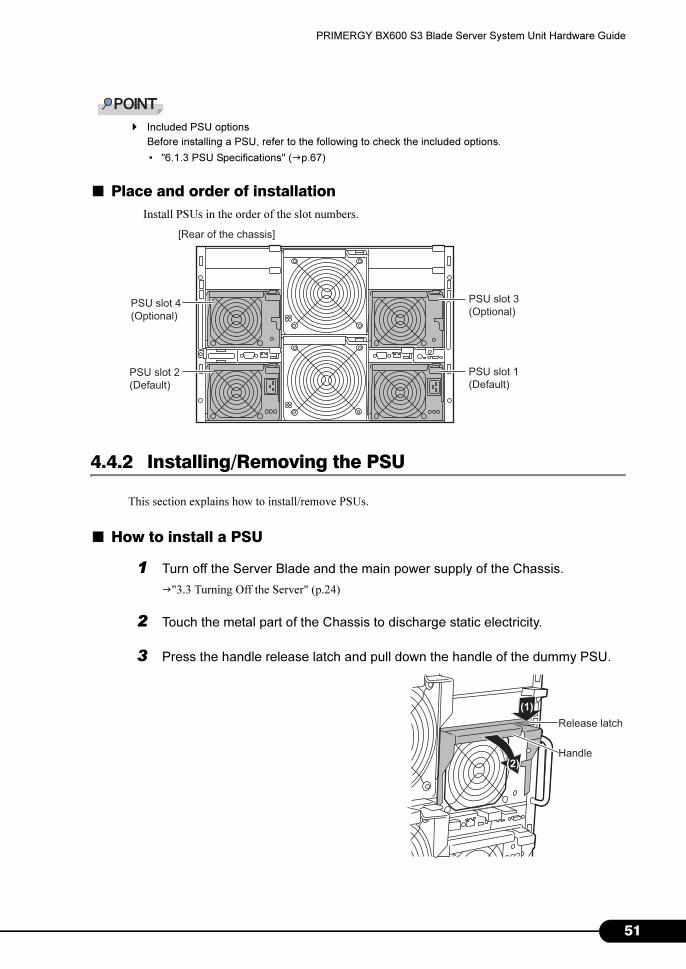
■ Place and order of installation
Install PSUs in the order of the slot numbers.
4.4.2 Installing/Removing the PSU
This section explains how to install/remove PSUs.
■ How to install a PSU
1 Turn off the Server Blade and the main power supply of the Chassis.
�"3.3 Turning Off the Server" (p.24)
2 Touch the metal part of the Chassis to discharge static electricity.
3 Press the handle release latch and pull down the handle of the dummy PSU.
[Rear of the chassis]
PSU slot 4(Optional)
PSU slot 2(Default)
PSU slot 3(Optional)
PSU slot 1(Default)
Release latch
Handle
(1)
(2)
51

5
Chapter 4 Installing Options
4 Remove the dummy PSU.
Remove the dummy PSU using both hands.
Be sure to keep the removed dummy PSU for
later use.
5 Install the PSU.
Check that the handle of the PSU is lowered. If
not, pull it down.
1. Using both hands, insert the PSU into
the PSU slot.
2. Pull up the handle to insert the PSU.
� When installing a PSU, check that the connector pins at the rear of the PSU are not
damaged or bent.
� Check that PSU is inserted firmly to the back of the PSU slot.
6 Connect the power supply cable to the PSU.
■ How to remove a PSU
To remove, simply reverse the installation procedure in "■ How to install a PSU" (�p.51).
• Do not operate when the PSU or dummy PSU has been removed.
(1)
(2)
2
PRIMERGY BX600 S3 Blade Server System Unit Hardware Guide
4.4.3 Replacing a PSU During Redundant Power Configuration
If one or two PSUs fail when the redundant power supply is configured, the PSU can be replaced
without turning off the power of the device. Check the location of the faulty PSU using the LED of the
failed PSU or ServerView.
After removing the PSU, be sure to replace it with a new unit.
■ How to replace a PSU
1 Disconnect the power cable of the PSU.
2 Remove the broken PSU.
�"■ How to remove a PSU" (p.52)
3 Install the new PSU.
�"■ How to install a PSU" (p.51)
4 Connect the power supply cable to the replaced PSU.
• Do not operate when the PSU or dummy PSU has been removed.
� When installing/removing a PSU during operation, first check that the system unit and other PSU/
dummy PSU are operating.
53

5
Chapter 4 Installing Options
4.5 Installing Advanced KVM Module
One KVM module is installed to the Chassis by default, which enables to input/output
using keyboard/display/mouse (KVM) of each Server Blade.
When an optional advanced KVM module is installed, apart from normal KVM input/
output, it is possible to redirect each Server Blade console from remote terminals via
LAN (graphic mode console redirection), and to emulate (virtualize) the floppy disk
drive or CD/DVD drive connected to the remote terminals and the Server Blades can
share the drives.
The advanced KVM module of the server supports the following functions:
• Graphic mode console redirection
• Remote USB floppy disk emulation
• Remote USB CD/DVD emulation
• Remote boot function from the emulated USB device
4.5.1 Before Installing Advanced KVM Module
■ KVM module connection
Connect the Management Blade, advanced KVM module, remote terminal, and hub to the same network
as shown in the figure below.
Management Blade 2
Remote terminal
Floppy disk drive
CD/DVD drive
[Rear of the chassis] Management Blade 1Advanced KVM Module
Network
4
PRIMERGY BX600 S3 Blade Server System Unit Hardware Guide
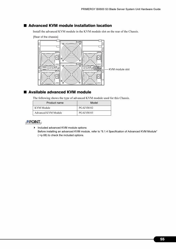
■ Advanced KVM module installation location
Install the advanced KVM module in the KVM module slot on the rear of the Chassis.
■ Available advanced KVM module
The following shows the type of advanced KVM module used for this Chassis.
� Included advanced KVM module options
Before installing an advanced KVM module, refer to "6.1.4 Specification of Advanced KVM Module"
(�p.68) to check the included options.
Product name Model
KVM Module PG-KVB102
Advanced KVM Module PG-KVB103
[Rear of the chassis]
KVM module slot
55

5
Chapter 4 Installing Options
4.5.2 Installing/Removing Advanced KVM Module
■ How to install an advanced KVM module
1 Turn off the Server Blade and the main power supply of the Chassis.
�"3.3 Turning Off the Server" (p.24)
2 Touch the metal part of the Chassis to discharge static electricity.
3 Remove the screws fixing the KVM module installed by default.
4 Remove the default KVM module.
1. Hold the handle out.
2. Pull the KVM module forward to
remove.
Screw
(2)
Handle(1)
6
PRIMERGY BX600 S3 Blade Server System Unit Hardware Guide
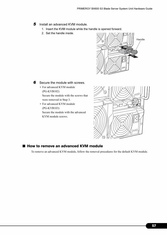
5 Install an advanced KVM module.
1. Insert the KVM module while the handle is opened forward.
2. Set the handle inside.
6 Secure the module with screws.
• For advanced KVM module
(PG-KVB102)
Secure the module with the screws that
were removed in Step 3.
• For advanced KVM module
(PG-KVB103)
Secure the module with the advanced
KVM module screws.
■ How to remove an advanced KVM module
To remove an advanced KVM module, follow the removal procedures for the default KVM module.
(1)
Handle
(2)
57

5
Chapter 4 Installing Options
4.6 Replacing the Management Blade
In this Chassis two Management Blades are installed by default and the
management/monitoring function is redundant.
It is necessary to replace a broken Management Blade. Contact an office listed in the
"Contact Information" of "Start Guide".
If one Management Blade fails, it is possible to replace the Management Blade without turning off the
main power supply of the Chassis or the Server Blade (hot-swap/hot-plug responsive). Check the slot
position of the failed Management Blade using the Management Blade error LED or ServerView.
For details about Management Blade, refer to "BX600 Management Blade Hardware Guide".
■ Management Blade slot
Management Blades are installed to all the slots by default.
� Have broken PSUs replaced as soon as possible.
� Always use the same Management Blade firmware version (except for when updating firmware).
[Rear of chassis]
Management Bladeslot 2
Management Bladeslot 1
8

PRIMERGY BX600 S3 Blade Server System Unit Hardware Guide
4.7 Replacing the System Fan Unit
This server supports the system fan redundancy function and "system down" can be
prevented even if one of the fans fails.
Also, replacement can take place while the main power is turned on (hot-swap/ hot-
plug).
It is necessary to replace a broken system fan. Contact an office listed in the "Contact
Information" of "Start Guide". Check which system fan has failed using the rear LED
or ServerView.
■ System fan unit redundancy
System fan is configured as follows.
• System fan unit 1 (internal fan × 2)
• System fan unit 2 (internal fan × 2)
• Replace the fan unit within 2 minutes of removing the broken one from the server.
• When removing a fan unit during operation always check that one fan is operating normally.
• When removing the fan unit, do not touch the fan unit connector of the Chassis. Doing so
may cause electric shock.
� If even one unit that makes up the system fan unit fails or is removed, redundancy is lost.
[Rear of the chassis]
System fan unit 1
System fan unit 2
59

6
Chapter 4 Installing Options
0
Chapter 5
Maintenance
This chapter explains how to perform daily
maintenance and the maintenance information.
5.1 Cleaning . . . . . . . . . . . . . . . . . . . . . . . . . . . . . . . . . . . . . 62
5.2 System Event Log . . . . . . . . . . . . . . . . . . . . . . . . . . . . . . 64
61
6
Chapter 5 Maintenance
5.1 Cleaning
To prevent trouble from occurring, clean the server regularly.
This server should be cleaned as follows.
5.1.1 Cleaning the Chassis
Wipe with a soft, dry cloth. For stains that do not come off with a dry cloth, wipe with a cloth lightly
dampened with a mild detergent. Once the stain has been removed, wipe off any remaining detergent
with a cloth dampened with water. When wiping the server, be sure that no moisture enters the Chassis.
Use a vacuum cleaner periodically to prevent dust buildup in ventilation holes.
� In dusty environments, dust piles up on the front and rear panels of the Chassis over short periods.
Install the Chassis in a different location to avoid failures.
5.1.2 Cleaning the Server Interior
In dusty environments, dust deposits in the server. Dust deposits may cause a server failure, fire, or
electric shock. To keep the PRIMERGY server in good condition, use a vacuum cleaner periodically to
remove dust deposits.
� Cleaning components
CPUs: Dust deposits must be removed because it will impair the cooling performance.
Fans: Remove dust from and around the fans.
Memory/expansion cards: Remove dust between memory modules and between expansion cards.
Remove dust from the connector before adding a memory module or an expansion card.
Internal hard disk units: Remove dust deposits from units and devices.
• Before cleaning, turn off the Chassis and unplug the power cables from the outlets. Also power
off peripherals and remove them from this product (�"3.3 Turning Off the Server" (p.24)).
Failure to do so may cause electric shock.
• Do not use any flammable aerosol cleaners. Doing so may damage the server as well as
cause fire.
• Do not disassemble the PSU when cleaning the server interior.
Doing so may cause failures or electric shock.
2

PRIMERGY BX600 S3 Blade Server System Unit Hardware Guide
5.1.3 Cleaning the Floppy Disk Drive
Prolonged use of the floppy disk drive accumulates dust on the device head (the part which reads/writes
data). A dirty head can impair the ability to read/write data to/from a floppy disk correctly. Clean the
head once every three months.
5.1.4 Optional Devices
For details about cleaning optional devices, refer to the each optional device manual.
� Be careful when removing components such as CPUs, memory modules, or hard disk units. Be sure
to install parts and cables in the original position.
� Leaving dust on the server can cause failure. Be sure to remove any dust from the server.
63

6
Chapter 5 Maintenance
5.2 System Event Log
The Chassis management is performed on the Management Blade. For event logs
relating to the Chassis, refer to the Management Blade event logs.
For details, refer to "BX600 Management Blade Hardware Guide".
4

Chapter 6
Technical Information
This chapter explains the specifications and
operational notes of the Chassis and optional
devices.
6.1 Specifications . . . . . . . . . . . . . . . . . . . . . . . . . . . . . . . . . 66
6.2 Number of Server Blades that can be Installed . . . . . . . . . 69
6.3 Operating Advanced KVM Module (PG-KVB102) . . . . . . . 70
6.4 Operating Advanced KVM Module (PG-KVB103) . . . . . . . 82
6.5 Non-durable Components . . . . . . . . . . . . . . . . . . . . . . . . 97
65

6
Chapter 6 Technical Information
6.1 Specifications
This section describes the specifications of the Chassis and optional devices.
6.1.1 Server Specifications
The specifications for the Chassis are shown in the table below.
For details about blades and peripheral devices, refer to each device manual.
Item Functions and Specifications
Product ID PGUR4SC2
Server Blade
No. of slots 10 (Standard: 0)
Redundant No
Hotplug Yes
Network Blade
No. of slotsNET1, NET2: 2 (Standard: 0)
NET3, NET4: 2 (Standard: 0)
Redundant Optional (Depending on network configuration)
Hotplug Yes
Management Blade
No. of slots 2 (Standard: 2)
Redundant Standard (1+1)
Hotplug Yes
KVM Module No. of slots 1 (Standard)
Power supply
No. of slots 4 (Standard: 2)
Redundant Optional (2+2)
Hotplug Yes (replace within 2 minutes after removing)
System fan unit
No. of slots 2 (two fan modules per slot)
Redundant Standard (2+2)
Hotplug Yes (replace within 2 minutes after removing)
External I/O port *1 Keyboard, mouse, video, LAN × 1 (when advanced KVM module is installed)
Keyboard / Mouse Optional
Dimension (Width × Depth × Height)446 × 735 × 308 mm (7U)
(483 × 800 × 308mm: including protrusion)
Weight Maximum 130kg
Power supply
Input power
supply
(Frequency)
200V-240V AC (50/60Hz)
Input voltage Max. 5,250W (18,900kJ / h)
Output voltage *2 Max. 4,200W
Outlet shape Refer to "6.1.5 Power Cable Selection" (�p.68)
*1: Switch the KVM inputs/outputs for 10 Server Blades and use them.
*2: Power consumption is the maximum power consumption of the PSUs.
The specifications for this Chassis are subject to be updated without any notice. Please be forewarned.
6
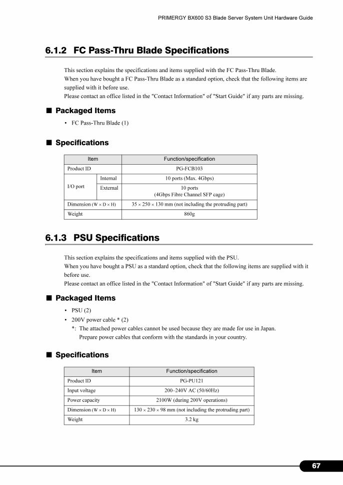
PRIMERGY BX600 S3 Blade Server System Unit Hardware Guide
6.1.2 FC Pass-Thru Blade Specifications
This section explains the specifications and items supplied with the FC Pass-Thru Blade.
When you have bought a FC Pass-Thru Blade as a standard option, check that the following items are
supplied with it before use.
Please contact an office listed in the "Contact Information" of "Start Guide" if any parts are missing.
■ Packaged Items
• FC Pass-Thru Blade (1)
■ Specifications
6.1.3 PSU Specifications
This section explains the specifications and items supplied with the PSU.
When you have bought a PSU as a standard option, check that the following items are supplied with it
before use.
Please contact an office listed in the "Contact Information" of "Start Guide" if any parts are missing.
■ Packaged Items
• PSU (2)
• 200V power cable * (2)
*: The attached power cables cannot be used because they are made for use in Japan.
Prepare power cables that conform with the standards in your country.
■ Specifications
Item Function/specification
Product ID PG-FCB103
I/O port
Internal 10 ports (Max. 4Gbps)
External 10 ports
(4Gbps Fibre Channel SFP cage)
Dimension (W × D × H) 35 × 250 × 130 mm (not including the protruding part)
Weight 860g
Item Function/specification
Product ID PG-PU121
Input voltage 200–240V AC (50/60Hz)
Power capacity 2100W (during 200V operations)
Dimension (W × D × H) 130 × 230 × 98 mm (not including the protruding part)
Weight 3.2 kg
67

6
Chapter 6 Technical Information
6.1.4 Specification of Advanced KVM Module
This section explains the specifications and items supplied with the Advanced KVM Module.
When you have bought an Advanced KVM Module as a standard option, check that the following items
are supplied with it before use.
Please contact an office listed in the "Contact Information" of "Start Guide" if any parts are missing.
■ Packaged Items
• Advanced KVM Module (1)
■ Specifications
6.1.5 Power Cable Selection
Use power cables that conform with the commercial power supply standard of your country.
They should also meet the following specifications.
Item Function/specification
Product ID PG-KVB102 PG-KVB103
I/O port Keyboard/ Mouse (PS/2), Video output
10BASE-T/100BASE-TX LAN connector
Dimension (W × D × H) 54 × 249 × 23.7 mm
Weight 300g
Item Specification
PSU inlet configuration IEC320-C19
Current capacity 16A
Voltage 200–240V AC
8

PRIMERGY BX600 S3 Blade Server System Unit Hardware Guide
6.2 Number of Server Blades that can be Installed
A maximum of 10 Server Blades can be installed on this Chassis. The number of
Server Blades that can be installed is limited by the Server Blade configuration, and
the type and number of installed PSUs. Read this section and then design the system
when choosing configurations or installing more Server Blades or Switch Blades.
• When additionally purchasing a Server Blade, check the number of Server Blades. If there are
too many Server Blades, the safety mechanism of the power control device may prevent the
power of the Server Blade being turned on.
� BX600, BX620S2 and BX660 Server Blades cannot be installed to this Chassis.
� Refer to the notes for each Server Blade by following the URL for details about how to estimate how
many Server Blades can be installed.
http://primergy.fujitsu.com
69
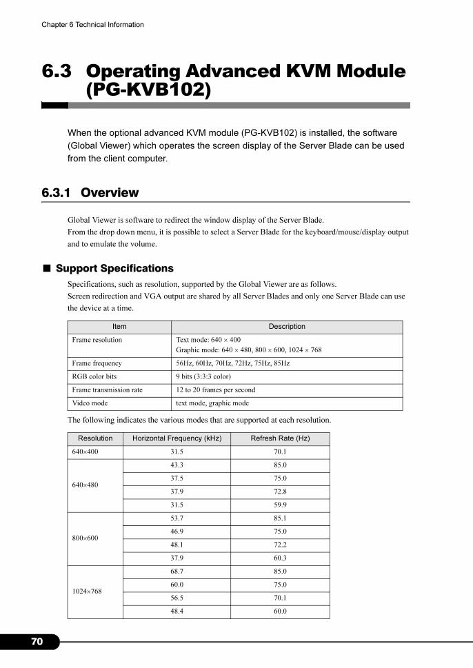
7
Chapter 6 Technical Information
6.3 Operating Advanced KVM Module (PG-KVB102)
When the optional advanced KVM module (PG-KVB102) is installed, the software
(Global Viewer) which operates the screen display of the Server Blade can be used
from the client computer.
6.3.1 Overview
Global Viewer is software to redirect the window display of the Server Blade.
From the drop down menu, it is possible to select a Server Blade for the keyboard/mouse/display output
and to emulate the volume.
■ Support Specifications
Specifications, such as resolution, supported by the Global Viewer are as follows.
Screen redirection and VGA output are shared by all Server Blades and only one Server Blade can use
the device at a time.
The following indicates the various modes that are supported at each resolution.
Item Description
Frame resolution Text mode: 640 × 400
Graphic mode: 640 × 480, 800 × 600, 1024 × 768
Frame frequency 56Hz, 60Hz, 70Hz, 72Hz, 75Hz, 85Hz
RGB color bits 9 bits (3:3:3 color)
Frame transmission rate 12 to 20 frames per second
Video mode text mode, graphic mode
Resolution Horizontal Frequency (kHz) Refresh Rate (Hz)
640×400 31.5 70.1
640×480
43.3 85.0
37.5 75.0
37.9 72.8
31.5 59.9
800×600
53.7 85.1
46.9 75.0
48.1 72.2
37.9 60.3
1024×768
68.7 85.0
60.0 75.0
56.5 70.1
48.4 60.0
0

PRIMERGY BX600 S3 Blade Server System Unit Hardware Guide
6.3.2 Checking the Operating Environment
The required conditions for the client computer (remote terminal) to operate Global Viewer are as
follows:
• Windows is running
• Internet Explorer is available
Before starting Global Viewer, check the following settings as well.
• ActiveX control of the client computer is set to enabled.
�"■ Setting ActiveX Control (Client)" (p.71)
• Mouse pointer acceleration of the Server Blade to be redirected is set to disabled.
�"■ Setting Mouse Pointer (Server Blade)" (p.73)
■ Setting ActiveX Control (Client)
Limit to ActiveX controls in the trusted sites of the client computer.
Follow the procedures below to add the advanced KVM module to the trusted sites and set ActiveX
controls of the trusted sites to enable.
1 In the Internet Explorer window, click [Tools] – [Internet Options...].
2 Click [Security] tab.
Contents in the [Security] tab appears.
71
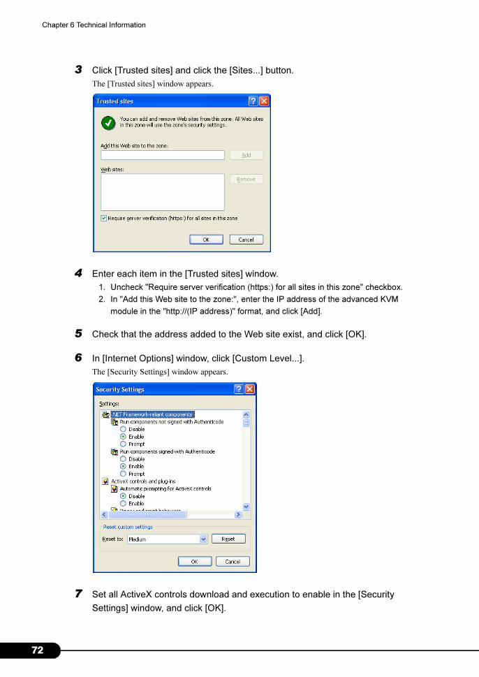
7
Chapter 6 Technical Information
3 Click [Trusted sites] and click the [Sites...] button.
The [Trusted sites] window appears.
4 Enter each item in the [Trusted sites] window.
1. Uncheck "Require server verification (https:) for all sites in this zone" checkbox.
2. In "Add this Web site to the zone:", enter the IP address of the advanced KVM
module in the "http://(IP address)" format, and click [Add].
5 Check that the address added to the Web site exist, and click [OK].
6 In [Internet Options] window, click [Custom Level...].
The [Security Settings] window appears.
7 Set all ActiveX controls download and execution to enable in the [Security
Settings] window, and click [OK].
2
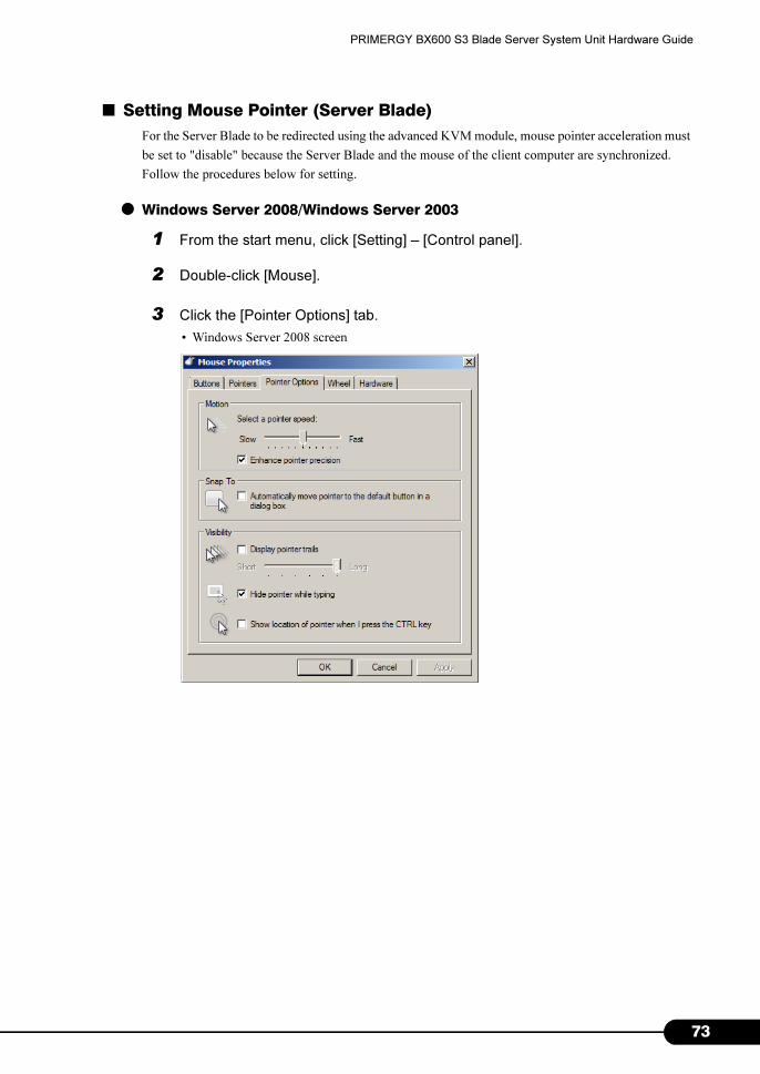
PRIMERGY BX600 S3 Blade Server System Unit Hardware Guide
■ Setting Mouse Pointer (Server Blade)
For the Server Blade to be redirected using the advanced KVM module, mouse pointer acceleration must
be set to "disable" because the Server Blade and the mouse of the client computer are synchronized.
Follow the procedures below for setting.
● Windows Server 2008/Windows Server 2003
1 From the start menu, click [Setting] – [Control panel].
2 Double-click [Mouse].
3 Click the [Pointer Options] tab.
• Windows Server 2008 screen
73

7
Chapter 6 Technical Information
• Windows Server 2003 screen
4 Set the speed to 50%, and uncheck "Enhance pointer precision" if it is checked.
5 Click [OK].
6 Select [Control] – [Mouse Sync] on Global Viewer menu.
7 Login with an account that has administrative privileges (Administrator, etc.)
and change status so the registry can be edited.
8 Change "Mouse Speed" in "/HKEY_USERS/.DEFAULT/Control Panel/Mouse"
from 1 to 0.
9 Restart the system.
4
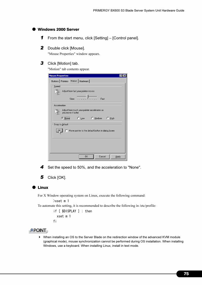
PRIMERGY BX600 S3 Blade Server System Unit Hardware Guide
● Windows 2000 Server
1 From the start menu, click [Setting] – [Control panel].
2 Double click [Mouse].
"Mouse Properties" window appears.
3 Click [Motion] tab.
"Motion" tab contents appear.
4 Set the speed to 50%, and the acceleration to "None".
5 Click [OK].
● Linux
For X Window operating system on Linux, execute the following command:
>xset m 1
To automate this setting, it is recommended to describe the following in /etc/profile:
if [ $DISPLAY ] ; then
xset m 1
fi
� When installing an OS to the Server Blade on the redirection window of the advanced KVM module
(graphical mode), mouse synchronization cannot be performed during OS installation. When installing
Windows, use a keyboard. When installing Linux, install in text mode.
75
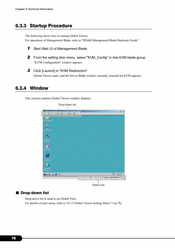
7
Chapter 6 Technical Information
6.3.3 Startup Procedure
The following shows how to startup Global Viewer.
For operations of Management Blade, refer to "BX600 Management Blade Hardware Guide".
1 Start Web UI of Management Blade.
2 From the setting item menu, select "KVM_Config" in Adv.KVM blade group.
"KVM Configuration" window appears.
3 Click [Launch] in "KVM Redirection".
Global Viewer starts, and the Server Blade window currently selected for KVM appears.
6.3.4 Window
This section explains Global Viewer window displays.
■ Drop-down list
Drop-down list is used to set Global View.
For details of each menu, refer to "6.3.5 Global Viewer Setting Menu" (�p.78).
Status bar
Drop-down list
6
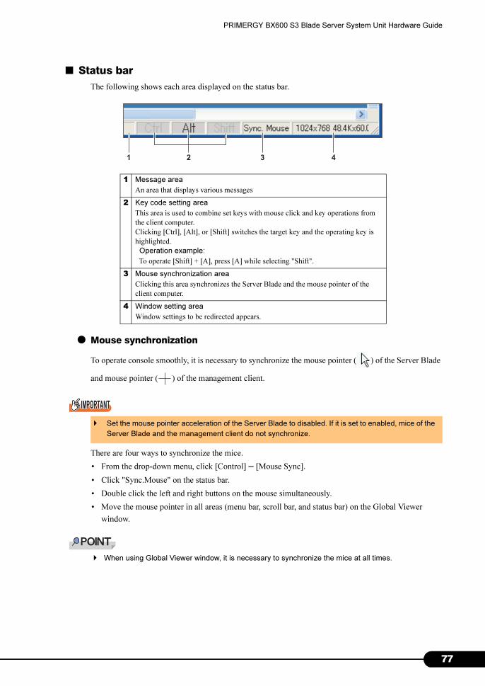
PRIMERGY BX600 S3 Blade Server System Unit Hardware Guide
■ Status bar
The following shows each area displayed on the status bar.
● Mouse synchronization
To operate console smoothly, it is necessary to synchronize the mouse pointer ( ) of the Server Blade
and mouse pointer ( ) of the management client.
There are four ways to synchronize the mice.
• From the drop-down menu, click [Control] – [Mouse Sync].
• Click "Sync.Mouse" on the status bar.
• Double click the left and right buttons on the mouse simultaneously.
• Move the mouse pointer in all areas (menu bar, scroll bar, and status bar) on the Global Viewer
window.
� When using Global Viewer window, it is necessary to synchronize the mice at all times.
1 Message area
An area that displays various messages
2 Key code setting area
This area is used to combine set keys with mouse click and key operations from
the client computer.
Clicking [Ctrl], [Alt], or [Shift] switches the target key and the operating key is
highlighted.
Operation example:
To operate [Shift] + [A], press [A] while selecting "Shift".
3 Mouse synchronization area
Clicking this area synchronizes the Server Blade and the mouse pointer of the
client computer.
4 Window setting area
Window settings to be redirected appears.
� Set the mouse pointer acceleration of the Server Blade to disabled. If it is set to enabled, mice of the
Server Blade and the management client do not synchronize.
1 3 42
77
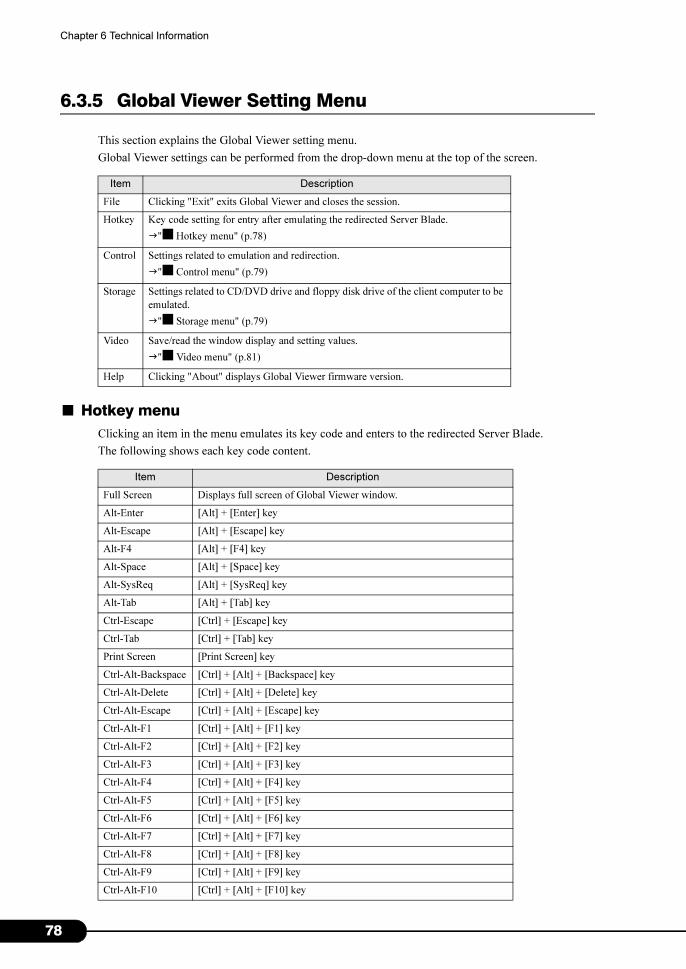
7
Chapter 6 Technical Information
6.3.5 Global Viewer Setting Menu
This section explains the Global Viewer setting menu.
Global Viewer settings can be performed from the drop-down menu at the top of the screen.
■ Hotkey menu
Clicking an item in the menu emulates its key code and enters to the redirected Server Blade.
The following shows each key code content.
Item Description
File Clicking "Exit" exits Global Viewer and closes the session.
Hotkey Key code setting for entry after emulating the redirected Server Blade.
�"■ Hotkey menu" (p.78)
Control Settings related to emulation and redirection.
�"■ Control menu" (p.79)
Storage Settings related to CD/DVD drive and floppy disk drive of the client computer to be
emulated.
�"■ Storage menu" (p.79)
Video Save/read the window display and setting values.
�"■ Video menu" (p.81)
Help Clicking "About" displays Global Viewer firmware version.
Item Description
Full Screen Displays full screen of Global Viewer window.
Alt-Enter [Alt] + [Enter] key
Alt-Escape [Alt] + [Escape] key
Alt-F4 [Alt] + [F4] key
Alt-Space [Alt] + [Space] key
Alt-SysReq [Alt] + [SysReq] key
Alt-Tab [Alt] + [Tab] key
Ctrl-Escape [Ctrl] + [Escape] key
Ctrl-Tab [Ctrl] + [Tab] key
Print Screen [Print Screen] key
Ctrl-Alt-Backspace [Ctrl] + [Alt] + [Backspace] key
Ctrl-Alt-Delete [Ctrl] + [Alt] + [Delete] key
Ctrl-Alt-Escape [Ctrl] + [Alt] + [Escape] key
Ctrl-Alt-F1 [Ctrl] + [Alt] + [F1] key
Ctrl-Alt-F2 [Ctrl] + [Alt] + [F2] key
Ctrl-Alt-F3 [Ctrl] + [Alt] + [F3] key
Ctrl-Alt-F4 [Ctrl] + [Alt] + [F4] key
Ctrl-Alt-F5 [Ctrl] + [Alt] + [F5] key
Ctrl-Alt-F6 [Ctrl] + [Alt] + [F6] key
Ctrl-Alt-F7 [Ctrl] + [Alt] + [F7] key
Ctrl-Alt-F8 [Ctrl] + [Alt] + [F8] key
Ctrl-Alt-F9 [Ctrl] + [Alt] + [F9] key
Ctrl-Alt-F10 [Ctrl] + [Alt] + [F10] key
8
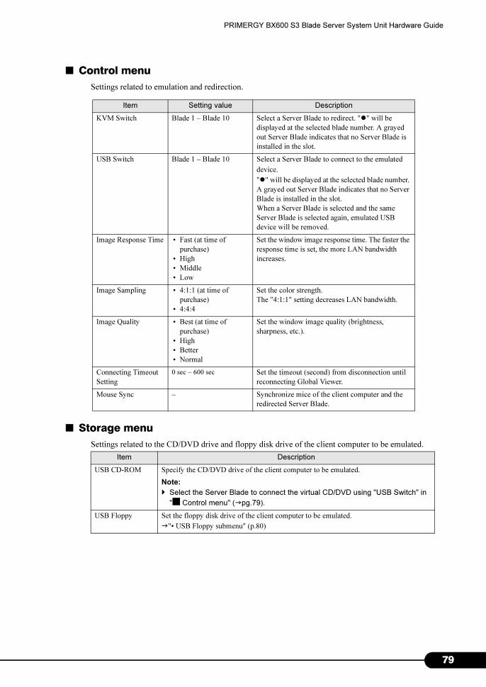
PRIMERGY BX600 S3 Blade Server System Unit Hardware Guide
■ Control menu
Settings related to emulation and redirection.
■ Storage menu
Settings related to the CD/DVD drive and floppy disk drive of the client computer to be emulated.
Item Setting value Description
KVM Switch Blade 1 – Blade 10 Select a Server Blade to redirect. "�" will be
displayed at the selected blade number. A grayed
out Server Blade indicates that no Server Blade is
installed in the slot.
USB Switch Blade 1 – Blade 10 Select a Server Blade to connect to the emulated
device.
"�" will be displayed at the selected blade number.
A grayed out Server Blade indicates that no Server
Blade is installed in the slot.
When a Server Blade is selected and the same
Server Blade is selected again, emulated USB
device will be removed.
Image Response Time • Fast (at time of
purchase)
• High
• Middle
• Low
Set the window image response time. The faster the
response time is set, the more LAN bandwidth
increases.
Image Sampling • 4:1:1 (at time of
purchase)
• 4:4:4
Set the color strength.
The "4:1:1" setting decreases LAN bandwidth.
Image Quality • Best (at time of
purchase)
• High
• Better
• Normal
Set the window image quality (brightness,
sharpness, etc.).
Connecting Timeout
Setting
0 sec – 600 sec Set the timeout (second) from disconnection until
reconnecting Global Viewer.
Mouse Sync – Synchronize mice of the client computer and the
redirected Server Blade.
Item Description
USB CD-ROM Specify the CD/DVD drive of the client computer to be emulated.
Note:
� Select the Server Blade to connect the virtual CD/DVD using "USB Switch" in
"■ Control menu" (�pg.79).
USB Floppy Set the floppy disk drive of the client computer to be emulated.
�"• USB Floppy submenu" (p.80)
79
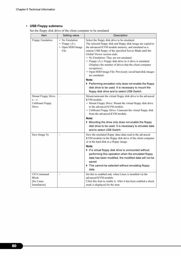
8
Chapter 6 Technical Information
• USB Floppy submenu
Set the floppy disk drive of the client computer to be emulated.
Item Setting value Description
Floppy Emulation • No Emulation
• Floppy (A:)
• Open HDD Image
File
Select the floppy disk drive to be emulated.
The selected floppy disk and floppy disk image are copied to
the advanced KVM module memory, and emulated as a
remote USB floppy of the specified Server Blade until the
Global Viewer session ends.
• No Emulation: They are not emulated.
• Floppy (A:): Floppy disk drive in A drive is emulated
(Displays the number of drives that the client computer
recognizes).
• Open HDD Image File: Previously saved hard disk images
are emulated.
Note:
� Performing emulation only does not enable the floppy
disk drive to be used. It is necessary to mount the
floppy disk drive and to select USB Switch.
Mount Floppy Drive
←→UnMount Floppy
Drive
– Mount/unmount the virtual floppy disk drive to the advanced
KVM module.
• Mount Floppy Drive: Mount the virtual floppy disk drive
to the advanced KVM module.
• UnMount Floppy Drive: Unmount the virtual floppy disk
from the advanced KVM module.
Note:
� Mounting the drive only does not enable the floppy
disk drive to be used. It is necessary to emulate data
and to select USB Switch.
Save Image To – Save the emulated floppy data (data read in the advanced
KVM module) in the floppy disk drive of the client computer
or in the hard disk as a floppy image.
Note:
� If a virtual floppy disk drive is unmounted without
performing this operation when the emulated floppy
data has been modified, the modified data will not be
saved.
� This cannot be selected without emulating floppy
data.
UFI Command
Block [for Linux
Installation]
– Set this to enabled only when Linux is installed via the
advanced KVM module.
Click this item to enable it. After it has been enabled a check
mark is displayed for the item.
0

PRIMERGY BX600 S3 Blade Server System Unit Hardware Guide
■ Video menu
Set the window display and save/read the setting values.
Item Description
Brightness Adjust brightness of the Global Viewer window by operating primitive
signal, red, green, and blue scale bars separately.
Contrast Adjust contrast of the Global Viewer window by operating primitive
signal, red, green, and blue scale bars separately.
Auto Adjust Automatically adjust the window brightness and contrast. During the
adjustment for approximately 10 seconds, the window is locked.
Load Default
Setting
Load the default settings.
Save Configuration Save the current setting information.
81

8
Chapter 6 Technical Information
6.4 Operating Advanced KVM Module (PG-KVB103)
When the optional Advanced KVM module (PG-KVB103) is installed, the following
operations are enabled.
• Selecting and switching the Server Blade, and status display/setting of the Server
Blade by using Menu window
�"6.4.1 OSCAR" (p.82)
• Operating the monitor of the Server Blade from the client computer
�"6.4.2 Video Viewer/Virtual Media" (p.89)
• Connecting floppy disk or CD/DVD drives from the client computer
�"6.4.2 Video Viewer/Virtual Media" (p.89)
6.4.1 OSCAR
Using the On Screen Configuration and Activity Reporting (OSCAR) function enables you to switch the
Server Blade on the Menu window.
Also, Server Blade status can be displayed and set by using OSCAR.
■ Operating environment
The following indicates the resolution and refresh rate that are supported by OSCAR.
Resolution Horizontal Frequency (kHz) Refresh Rate (Hz)
640×480
31.5 60
37.9 72
37.5 75
43.3 85
800×600
37.9 60
48.1 72
46.9 75
53.7 85
1024×768
48.4 60
56.5 72
60.0 75
68.7 85
1152×864 67.5 75
1280×76860.0 60
85.9 85
2
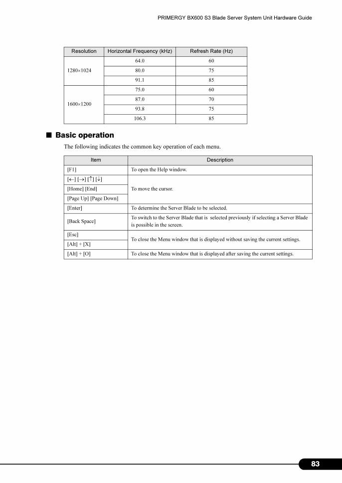
PRIMERGY BX600 S3 Blade Server System Unit Hardware Guide
■ Basic operation
The following indicates the common key operation of each menu.
1280×1024
64.0 60
80.0 75
91.1 85
1600×1200
75.0 60
87.0 70
93.8 75
106.3 85
Item Description
[F1] To open the Help window.
[←] [→] [↑] [↓]
To move the cursor.[Home] [End]
[Page Up] [Page Down]
[Enter] To determine the Server Blade to be selected.
[Back Space]To switch to the Server Blade that is selected previously if selecting a Server Blade
is possible in the screen.
[Esc]To close the Menu window that is displayed without saving the current settings.
[Alt] + [X]
[Alt] + [O] To close the Menu window that is displayed after saving the current settings.
Resolution Horizontal Frequency (kHz) Refresh Rate (Hz)
83
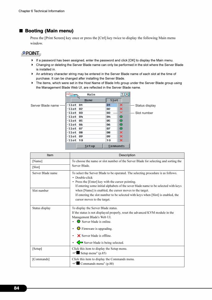
8
Chapter 6 Technical Information
■ Booting (Main menu)
Press the [Print Screen] key once or press the [Ctrl] key twice to display the following Main menu
window.
� If a password has been assigned, enter the password and click [OK] to display the Main menu.
� Changing or deleting the Server Blade name can only be performed in the slot where the Server Blade
is installed in.
� An arbitrary character string may be entered in the Server Blade name of each slot at the time of
purchase. It can be changed after installing the Server Blade.
� The items, which were set in the Host Name of Blade Info group under the Server Blade group using
the Management Blade Web UI, are reflected in the Server Blade name.
Item Description
[Name] To choose the name or slot number of the Server Blade for selecting and sorting the
Server Blade.[Slot]
Server Blade name To select the Server Blade to be operated. The selecting procedure is as follows.
• Double-click
• Press the [Enter] key with the cursor pointing.
If entering some initial alphabets of the sever blade name to be selected with keys
when [Name] is enabled, the cursor moves to the target.
If entering the slot number to be selected with keys when [Slot] is enabled, the
cursor moves to the target.
Slot number
Status display To display the Server Blade status.
If the status is not displayed properly, reset the advanced KVM module in the
Management Blade's Web UI.
• Server blade is online.
• Firmware is upgrading.
• Server blade is offline.
• Server blade is being selected.
[Setup] Click this item to display the Setup menu.
�"■ Setup menu" (p.85)
[Commands] Click this item to display the Commands menu.
�"■ Commands menu" (p.88)
Server Blade name Status display
Slot number
4
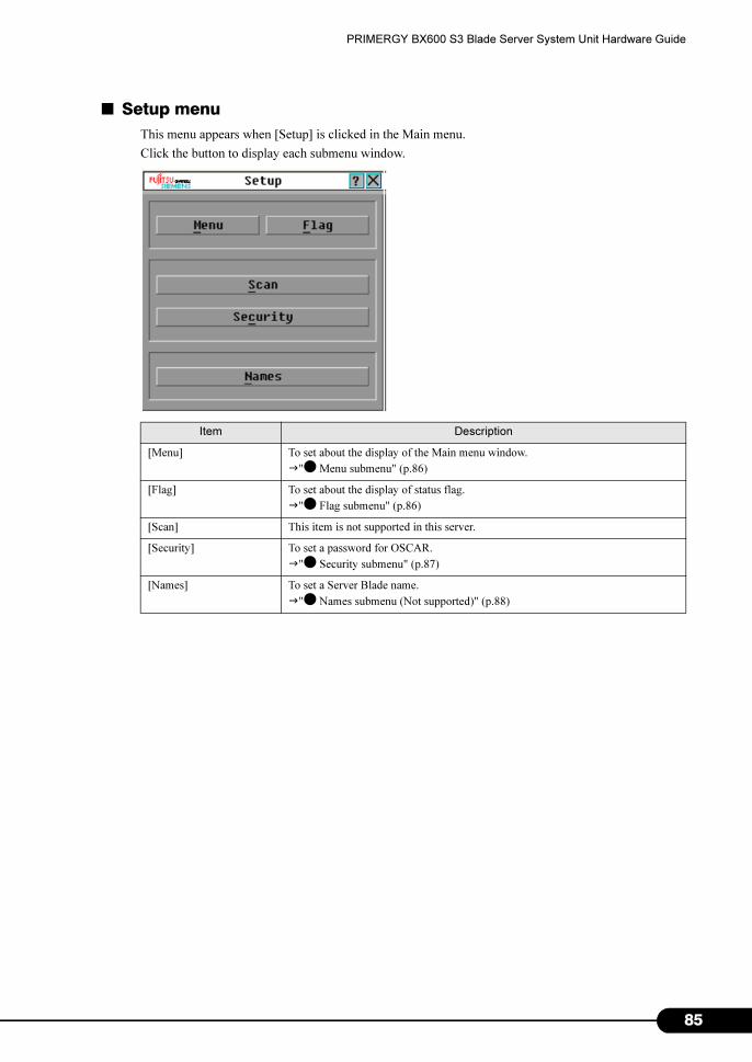
PRIMERGY BX600 S3 Blade Server System Unit Hardware Guide
■ Setup menu
This menu appears when [Setup] is clicked in the Main menu.
Click the button to display each submenu window.
Item Description
[Menu] To set about the display of the Main menu window.
�"● Menu submenu" (p.86)
[Flag] To set about the display of status flag.
�"● Flag submenu" (p.86)
[Scan] This item is not supported in this server.
[Security] To set a password for OSCAR.
�"● Security submenu" (p.87)
[Names] To set a Server Blade name.
�"● Names submenu (Not supported)" (p.88)
85
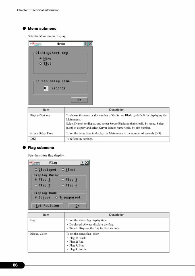
8
Chapter 6 Technical Information
● Menu submenu
Sets the Main menu display.
● Flag submenu
Sets the status flag display.
Item Description
Display/Sort key To choose the name or slot number of the Server Blade by default for displaying the
Main menu.
Select [Name] to display and select Server Blades alphabetically by name. Select
[Slot] to display and select Server Blades numerically by slot number.
Screen Delay Time To set the delay time to display the Main menu in the number of seconds (0-9).
[OK] To reflect the settings.
Item Description
Flag To set the status flag display time.
• Displayed: Always displays the flag.
• Timed: Displays the flag for five seconds.
Display Color To set the status flag color.
• Flag 1: Black
• Flag 2: Red
• Flag 3: Blue
• Flag 4: Purple
6
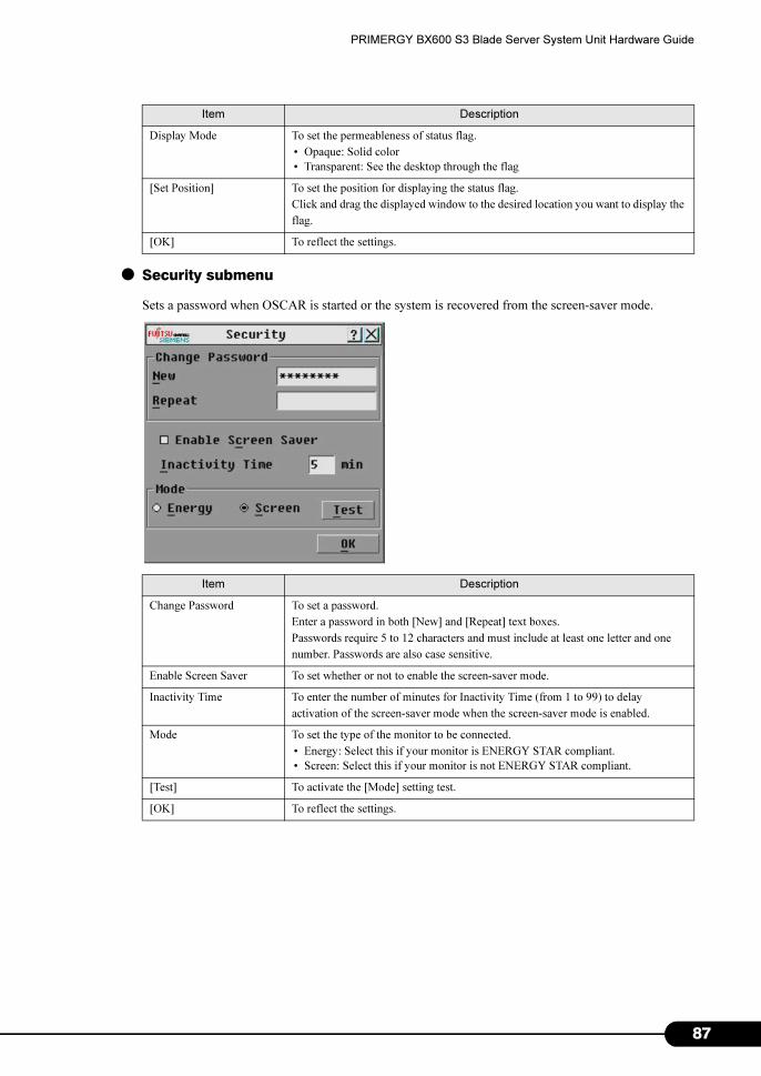
PRIMERGY BX600 S3 Blade Server System Unit Hardware Guide
● Security submenu
Sets a password when OSCAR is started or the system is recovered from the screen-saver mode.
Display Mode To set the permeableness of status flag.
• Opaque: Solid color
• Transparent: See the desktop through the flag
[Set Position] To set the position for displaying the status flag.
Click and drag the displayed window to the desired location you want to display the
flag.
[OK] To reflect the settings.
Item Description
Change Password To set a password.
Enter a password in both [New] and [Repeat] text boxes.
Passwords require 5 to 12 characters and must include at least one letter and one
number. Passwords are also case sensitive.
Enable Screen Saver To set whether or not to enable the screen-saver mode.
Inactivity Time To enter the number of minutes for Inactivity Time (from 1 to 99) to delay
activation of the screen-saver mode when the screen-saver mode is enabled.
Mode To set the type of the monitor to be connected.
• Energy: Select this if your monitor is ENERGY STAR compliant.
• Screen: Select this if your monitor is not ENERGY STAR compliant.
[Test] To activate the [Mode] setting test.
[OK] To reflect the settings.
Item Description
87

8
Chapter 6 Technical Information
● Names submenu (Not supported)
Sets the Server Blade name.
The procedure for changing the Server Blade name is as follows.
1 Select the Server Blade name to be changed in one of the following ways.
• Double-click
• Click [Modify] selecting the Server Blade name.
The [Name Modify] window appears.
2 Enter the Server Blade name in the [New Name] text box, and click [OK].
3 Check that the Server Blade name is properly set in the Names submenu, and
click [OK].
■ Commands menu
Checks the version of the advanced KVM module.
Item Description
Scan Enable This item is not supported in this server.
[Display Versions] To display the version information of the advanced KVM module.
8
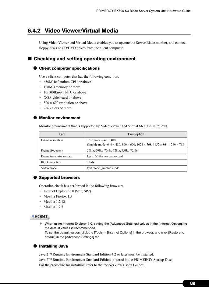
PRIMERGY BX600 S3 Blade Server System Unit Hardware Guide
6.4.2 Video Viewer/Virtual Media
Using Video Viewer and Virtual Media enables you to operate the Server Blade monitor, and connect
floppy disks or CD/DVD drives from the client computer.
■ Checking and setting operating environment
● Client computer specifications
Use a client computer that has the following condition.
• 650MHz Pentium CPU or above
• 128MB memory or more
• 10/100Base-T NTC or above
• XGA video card or above
• 800 × 600 resolution or above
• 256 colors or more
● Monitor environment
Monitor environment that is supported by Video Viewer and Virtual Media is as follows.
● Supported browsers
Operation check has performed in the following browsers.
• Internet Explorer 6.0 (SP1, SP2)
• Mozilla Firefox 1.5
• Mozilla 1.7.12
• Mozilla 1.7.5
� When using Internet Explorer 6.0, setting the [Advanced Settings] values in the [Internet Options] to
the default values is recommended.
To set the default values, click the [Tools] – [Internet Options] in the browser, and click [Restore to
default] in the [Advanced Settings] tab.
● Installing Java
Java 2™ Runtime Environment Standard Edition 4.2 or later must be installed.
Java 2™ Runtime Environment Standard Edition is stored in the PRIMERGY Startup Disc.
For the procedure for installing, refer to the "ServerView User’s Guide".
Item Description
Frame resolution Text mode: 640 × 400
Graphic mode: 640 × 480, 800 × 600, 1024 × 768, 1152 × 864, 1280 × 768
Frame frequency 56Hz, 60Hz, 70Hz, 72Hz, 75Hz, 85Hz
Frame transmission rate Up to 30 frames per second
RGB color bits 7 bits
Video mode text mode, graphic mode
89

9
Chapter 6 Technical Information
● Registering certificate
The Management Blade and advanced KVM module certificates must be signed by a trusted certificate
authority known in advance to the browser.
Register the certificate according to the following procedure.
1 Copy the following file in the PRIMERGY Startup Disc, and uncompress it.
[CD/DVD drive]:\SSL certificate\RemoteView CA Cert.zip
2 Double-click on the [RemoteView CA Cert.der] certificate file.
The [Certificate] window appears.
3 Click [Install Certificate].
The [Welcome to the Certificate Import Wizard] window appears.
0

PRIMERGY BX600 S3 Blade Server System Unit Hardware Guide
4 Click [Next>].
The [Certificate Store] window appears.
5 Be sure to select the [Automatically select the certificate store based on the
type of certificate] radio button, and click [Next>].
The [Completing the Certificate Import Wizard] window appears.
91
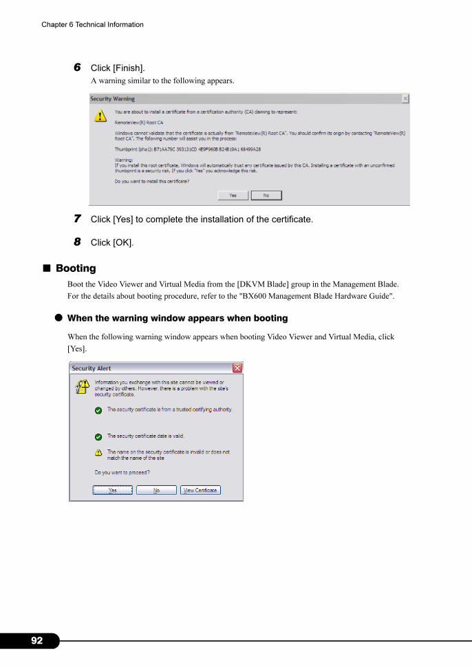
9
Chapter 6 Technical Information
6 Click [Finish].
A warning similar to the following appears.
7 Click [Yes] to complete the installation of the certificate.
8 Click [OK].
■ Booting
Boot the Video Viewer and Virtual Media from the [DKVM Blade] group in the Management Blade.
For the details about booting procedure, refer to the "BX600 Management Blade Hardware Guide".
● When the warning window appears when booting
When the following warning window appears when booting Video Viewer and Virtual Media, click
[Yes].
2
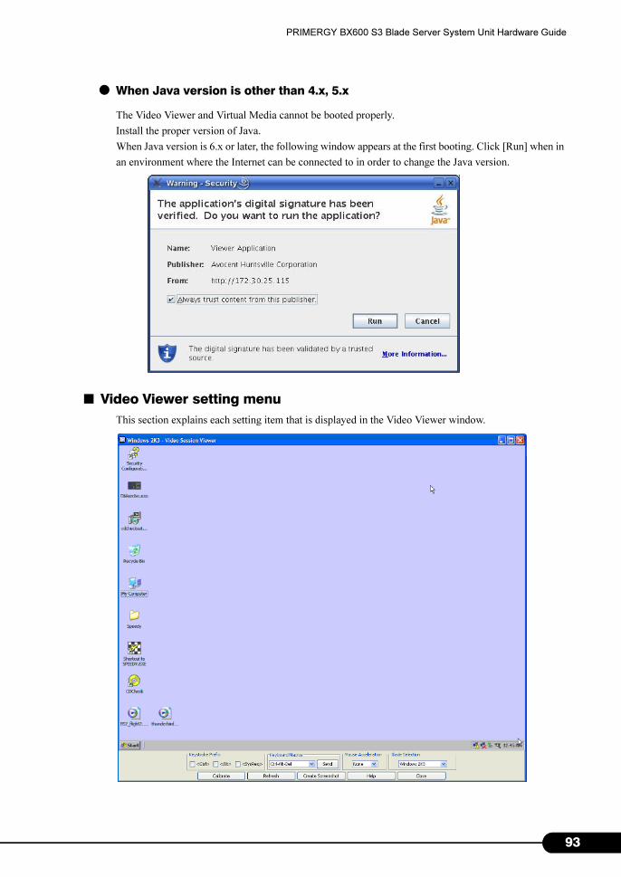
PRIMERGY BX600 S3 Blade Server System Unit Hardware Guide
● When Java version is other than 4.x, 5.x
The Video Viewer and Virtual Media cannot be booted properly.
Install the proper version of Java.
When Java version is 6.x or later, the following window appears at the first booting. Click [Run] when in
an environment where the Internet can be connected to in order to change the Java version.
■ Video Viewer setting menu
This section explains each setting item that is displayed in the Video Viewer window.
93
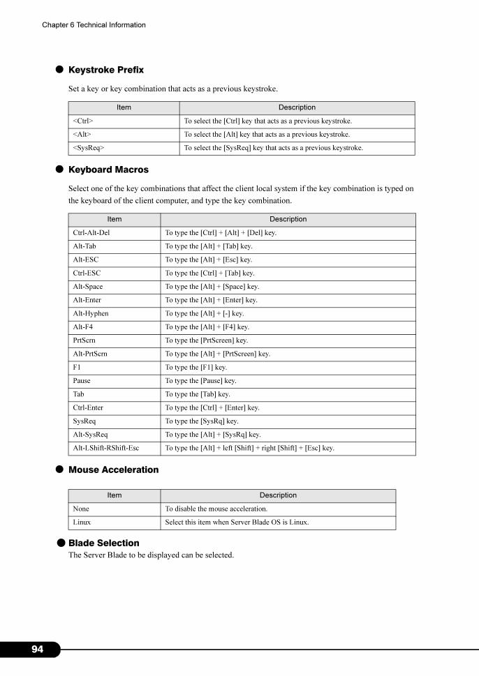
9
Chapter 6 Technical Information
● Keystroke Prefix
Set a key or key combination that acts as a previous keystroke.
● Keyboard Macros
Select one of the key combinations that affect the client local system if the key combination is typed on
the keyboard of the client computer, and type the key combination.
● Mouse Acceleration
● Blade Selection
The Server Blade to be displayed can be selected.
Item Description
<Ctrl> To select the [Ctrl] key that acts as a previous keystroke.
<Alt> To select the [Alt] key that acts as a previous keystroke.
<SysReq> To select the [SysReq] key that acts as a previous keystroke.
Item Description
Ctrl-Alt-Del To type the [Ctrl] + [Alt] + [Del] key.
Alt-Tab To type the [Alt] + [Tab] key.
Alt-ESC To type the [Alt] + [Esc] key.
Ctrl-ESC To type the [Ctrl] + [Tab] key.
Alt-Space To type the [Alt] + [Space] key.
Alt-Enter To type the [Alt] + [Enter] key.
Alt-Hyphen To type the [Alt] + [-] key.
Alt-F4 To type the [Alt] + [F4] key.
PrtScrn To type the [PrtScreen] key.
Alt-PrtScrn To type the [Alt] + [PrtScreen] key.
F1 To type the [F1] key.
Pause To type the [Pause] key.
Tab To type the [Tab] key.
Ctrl-Enter To type the [Ctrl] + [Enter] key.
SysReq To type the [SysRq] key.
Alt-SysReq To type the [Alt] + [SysRq] key.
Alt-LShift-RShift-Esc To type the [Alt] + left [Shift] + right [Shift] + [Esc] key.
Item Description
None To disable the mouse acceleration.
Linux Select this item when Server Blade OS is Linux.
4

PRIMERGY BX600 S3 Blade Server System Unit Hardware Guide
● Calibrate
When clicking the [Calibrate], the [Manual Video Adjust] window appears.
Adjust the window display.
● Refresh
Refresh the screen.
● Create Screenshot
Save the screen as an image.
Item Description
To fine adjust the sampling by pixel (0 to 30).
To adjust horizontal position of the image capture (0 to 400).
To adjust vertical position of the image capture (0 to 40).
To adjust contrast (0 to 255).
To adjust brightness (0 to 255).
To adjust the noise threshold by pixel (0 to 15).
To adjust the video automatically.
To refresh the image.
To display video test pattern.
Performance Monitor To display the transfer speed of the monitor.
95

9
Chapter 6 Technical Information
■ Virtual Media setting menu
When booting the Virtual Media, the following window appears.
Select the floppy disk drive or CD/DVD drive to be connected, and click [Connect Floppy] or [Connect
CD/DVD] to connect the floppy disk drive or CD/DVD drive on the network.
6
PRIMERGY BX600 S3 Blade Server System Unit Hardware Guide
6.5 Non-durable Components
This Chassis monitors the status of power supply unit (PSU), sending notification
when they need to be replaced. Management Blade performs monitoring and
notifying.
The following function is available.
• By this, the Chassis can evade shutdowns due to failure of these component.
The following are the non-durable components.
• PSU
• Dummy PSU
■ Management Blade Settings for Non-durable Components
• Perform Management Blade settings for non-durable components before operating the server. For
details, refer to "BX600 Management Blade Hardware Guide".
• If you use this Chassis without performing Management Blade settings, no notification will be sent,
which informs when a component has reached the near-end of its lifetime. This will result in
unnecessary system shutdowns.
• Non-durable components are supposed to be replaced in the periodical maintenance performed after
these messages appear. These parts can be continuously used for approximately one year after the
message.
6.5.1 Component Lifetime Information Browse/Setting Menu
The running hours and lifetime of the non-durable components of this Chassis can be displayed using
the Web UI of the Management Blades.
The following items must be checked or set in the Web UI ([System Property] - [Environ./Maintenance]
- [Power Supply]) of the Management Blades when commencing use of this Chassis and when such a
component is being replaced. For details about display methods and operations, refer to "BX600
Management Blade Hardware Guide".
• Installation Date
Enter the installation/replacement date of the PSU and dummy PSU in this Chassis.
• Life Time
Displays the lifetime of the system fan unit, PSU and dummy PSU in this Chassis. It is measured in
units of hours (hrs). If running time exceeds this value, event log is recorded/notified.
97
9
Chapter 6 Technical Information
■ Resetting lifetime
When operating the system, if Management Blade information is lost, it is necessary to reset lifetime.
Calculation is as follows: Enter the calculated value in Time Limited Count (lifetime) for the PSU and
dummy PSU.
Lifetime= 35000 - months of use × 30 × 24 × usage ratio/month × usage ratio/day
• Example
When the system running for eight hours per day and twenty days per month loses information after
four months of use:
Lifetime = 35000 - months of use (4) × 30 × 24 × usage ratio/month (20/30) ×
usage ratio/day (8/24) = 34360 hours
� The lifetime of the PSU and dummy PSU is suspended only when the main power of this Chassis is
disconnected.
The following shows the lifetime for non-durable components in this Chassis. Use them as a rough
estimate.
Note that the values listed below correspond to a temperature environment ranging from 10-35°C. These
values will drop by approximately half with a 10°C increase in temperature.
� The lifetime of non-durable components fluctuates according to the ambient temperature. The lifetime of such
components is calculated on the assumption that the Chassis is used at an annual average temperature of 25°C.
Thus, if the Chassis is used in an environment where the annual average temperature exceeds 25°C, the lifetime
can be shorter.
In general, if the temperature increases by 10°C (i.e. an annual average temperature of 35°C), the lifetime of non-
durable components will be reduced to approximately half.
� Do not change the lifetime. If changed replacement notification may not be performed correctly.
Only change the value when running hours information has been lost. Running hours information is
lost only when the front control board of the Chassis is replaced.
non-durable component Life time Comment
PSU, Dummy PSU approx. 35,000hrs 24 hr/day: approx. 3 yrs
8
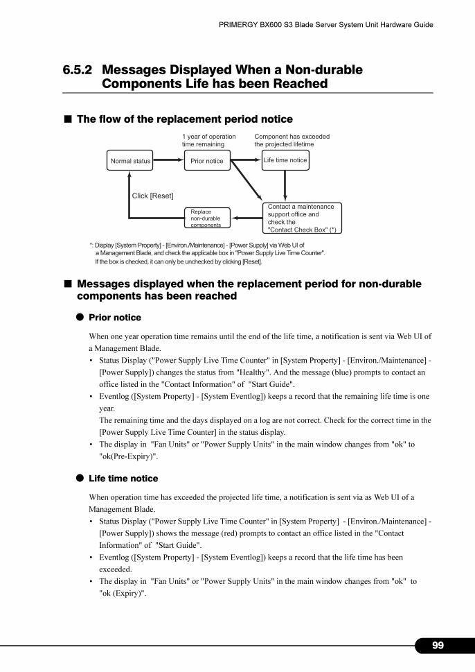
PRIMERGY BX600 S3 Blade Server System Unit Hardware Guide
6.5.2 Messages Displayed When a Non-durable Components Life has been Reached
■ The flow of the replacement period notice
■ Messages displayed when the replacement period for non-durable components has been reached
● Prior notice
When one year operation time remains until the end of the life time, a notification is sent via Web UI of
a Management Blade.
• Status Display ("Power Supply Live Time Counter" in [System Property] - [Environ./Maintenance] -
[Power Supply]) changes the status from "Healthy". And the message (blue) prompts to contact an
office listed in the "Contact Information" of "Start Guide".
• Eventlog ([System Property] - [System Eventlog]) keeps a record that the remaining life time is one
year.
The remaining time and the days displayed on a log are not correct. Check for the correct time in the
[Power Supply Live Time Counter] in the status display.
• The display in "Fan Units" or "Power Supply Units" in the main window changes from "ok" to
"ok(Pre-Expiry)".
● Life time notice
When operation time has exceeded the projected life time, a notification is sent via as Web UI of a
Management Blade.
• Status Display ("Power Supply Live Time Counter" in [System Property] - [Environ./Maintenance] -
[Power Supply]) shows the message (red) prompts to contact an office listed in the "Contact
Information" of "Start Guide".
• Eventlog ([System Property] - [System Eventlog]) keeps a record that the life time has been
exceeded.
• The display in "Fan Units" or "Power Supply Units" in the main window changes from "ok" to
"ok (Expiry)".
Normal status Life time notice
Contact a maintenance
support office and
check the
"Contact Check Box" (*)
Prior notice
Replace
non-durable
components
1 year of operation
time remaining
Click [Reset]
Component has exceeded
the projected lifetime
*: Display [System Property] - [Environ./Maintenance] - [Power Supply] via Web UI of
a Management Blade, and check the applicable box in "Power Supply Live Time Counter".
If the box is checked, it can only be unchecked by clicking [Reset].
99

1
Chapter 6 Technical Information
● Management after the notice
Perform the following setup promptly, after a notification of end of life time.
1 Contact an office listed in the "Contact Information" of "Start Guide".
2 Check the "Contact Check Box" of corresponding PSU in the Web UI of the
Management Blade.
1. Click [System Property] - [Environ./Maintenance] - [Power Supply].
2. Check the "Contact Check Box" of the corresponding PSU in the "Power Supply
Live Time Counter".
The date checked in the "Contact Check Box" is displayed in the "Expiry Reporting Date".
3 Replace the PSU/dummy PSU with a new one.
�"4.4 Installing the PSU" (p.50)
4 Click [Reset] for the corresponding PSU in the Web UI of the Management
Blade.
1. Click [System Property] - [Environ./Maintenance] - [Power Supply].
2. Click [Reset] for the corresponding PSU in the "Power Supply Live Time Counter".
The check in "Contact Check Box" is removed and "Status" returns to "Healthy".
■ Messages notified by SNMP trap
The following explains the messages notified by SNMP trap when the lifetime of non-durable
components has been reached.
If a message is displayed, check the event log and replace the recorded component that has reached its
service life.
The following table lists each message and the appropriate action.
Message Description Action
Servers % live time has exceeded the limited count. This message signals that a component's service life
has been reached. Check the event log and contact an
office listed in the "Contact Information" of "Start
Guide". The Management Agent System Name is
displayed in "%s".
00
PRIMERGY BX600 S3 Blade Server System Unit Hardware Guide
Index
A
AC Power LED . . . . . . . . . . . . . . . . . . . . . . 14
Advanced KVM module . . . . . . . . . . . . . . . 54
Installing . . . . . . . . . . . . . . . . . . . . . . . . 56
Removing . . . . . . . . . . . . . . . . . . . . . . . 57
Specification . . . . . . . . . . . . . . . . . . . . . 68
C
Cleaning the Chassis . . . . . . . . . . . . . . . . . 62
Cleaning the Floppy Disk Drive . . . . . . . . . . 63
Connector
Display/USB expansion connector . . . . 11
Fibre Channel connector . . . . . . . . . . . . 13
Serial port connector . . . . . . . . . . . . . . . 14
10BASE-T/100BASE-TX connector 13, 14
D
DC Power LED . . . . . . . . . . . . . . . . . . . . . . 14
E
Expansion card active link display LED. . . . 11
Expansion card slot. . . . . . . . . . . . . . . . . . . 11
F
FC Network Blade
Installing . . . . . . . . . . . . . . . . . . . . . . . . 48
Removing . . . . . . . . . . . . . . . . . . . . . . . 47
Fibre Channel connection in the Chassis . . 41
Fibre Channel error LED. . . . . . . . . . . . . . . 13
Fibre Channel link LED . . . . . . . . . . . . . . . . 13
Floppy disk
Ejecting . . . . . . . . . . . . . . . . . . . . . . . . . 27
Inserting . . . . . . . . . . . . . . . . . . . . . . . . 27
Front maintenance LED . . . . . . . . . . . . . . . 10
Front maintenance switch . . . . . . . . . . . . . . 10
H
Hard disk access display LED. . . . . . . . . . . 11
Hard disk failure LED . . . . . . . . . . . . . . . . . 11
Hard disk status LED . . . . . . . . . . . . . . . . . 11
I
Inlet. . . . . . . . . . . . . . . . . . . . . . . . . . . . . . . 13
Installing options . . . . . . . . . . . . . . . . . . . . . 32
K
KVM connector . . . . . . . . . . . . . . . . . . . . . . .12
KVM module slot . . . . . . . . . . . . . . . . . . . . .12
KVM power LED. . . . . . . . . . . . . . . . . . . . . .13
KVM select LED . . . . . . . . . . . . . . . . . . . . . .11
KVM select switch . . . . . . . . . . . . . . . . . . . .11
KVM Switch . . . . . . . . . . . . . . . . . . . . . . . . .30
L
LAN active LED . . . . . . . . . . . . . . . . . . .13, 14
LAN active link display LED . . . . . . . . . . . . .11
LAN connection in the Chassis . . . . . . . . . . .38
LAN link LED . . . . . . . . . . . . . . . . . . . . .13, 14
LAN Network Blade
Installing . . . . . . . . . . . . . . . . . . . . . . . . .45
Remove . . . . . . . . . . . . . . . . . . . . . . . . .44
M
Main power LED. . . . . . . . . . . . . . . . . . . . . .10
Main power switch . . . . . . . . . . . . . . . . . . . .10
Management Blade . . . . . . . . . . . . . . . . . . .12
Management Blade error LED . . . . . . . . . . .14
Management Blade master LED. . . . . . . . . .14
Messages displayed when the replacement
period for non-durable components has been
reached . . . . . . . . . . . . . . . . . . . . . . . . . . .99
N
Network blade slot . . . . . . . . . . . . . . . . . . . .12
P
Power Supply Unit . . . . . . . . . . . . . . . . . . . .12
PSU
Installation. . . . . . . . . . . . . . . . . . . . . . . .51
Removing . . . . . . . . . . . . . . . . . . . . . . . .52
Replacing a PSU during power redundant
power configuration. . . . . . . . . . . . . . . . .53
Specifications . . . . . . . . . . . . . . . . . . . . .67
R
Rack
Opening the Rack Door. . . . . . . . . . . . . .20
Rack key. . . . . . . . . . . . . . . . . . . . . . . . . . . .20
Rear maintenance LED . . . . . . . . . . . . . . . .12
Rear maintenance switch . . . . . . . . . . . . . . .12
101

1
S
Security
Hardware . . . . . . . . . . . . . . . . . . . . . . . . 16
Software. . . . . . . . . . . . . . . . . . . . . . . . . 17
Server Specifications . . . . . . . . . . . . . . . . . . 66
Server blade
Installing. . . . . . . . . . . . . . . . . . . . . . . . . 36
Removing. . . . . . . . . . . . . . . . . . . . . . . . 35
Server blade power LED . . . . . . . . . . . . . . . 11
Server blade power switch . . . . . . . . . . . . . . 11
Server blade slot . . . . . . . . . . . . . . . . . . . . . 10
Storage blade
Installing. . . . . . . . . . . . . . . . . . . . . . . . . 36
Removing. . . . . . . . . . . . . . . . . . . . . . . . 35
System event log . . . . . . . . . . . . . . . . . . . . . 64
System fan module error LED . . . . . . . . . . . 14
System fan module LED . . . . . . . . . . . . . . . 14
T
Turn
OFF . . . . . . . . . . . . . . . . . . . . . . . . . . . . 24
ON . . . . . . . . . . . . . . . . . . . . . . . . . . . . . 22
W
Warning LED . . . . . . . . . . . . . . . . . . . . . . . . 14
Numeric
2.5-inch storage bay . . . . . . . . . . . . . . . . . . 11
02
• The contents may be revised without prior notice.
• Fujitsu assumes no liability for damages to third party copyrights or other rights
arising from the use of any information in this manual.
• No part of this manual may be reproduced in any form without the prior written
permission of Fujitsu.
PRIMERGY BX600 S3 Blade Server System Unit
Hardware Guide
B7FH-5601-01ENZ0-00
Issued in
Issued by
August, 2008
FUJITSU LIMITED