primer on durability of nuclear power plant reinforced ... ornl/tm-2006/529 primer on durability of...
TRANSCRIPT

NUREG/CR-6927 ORNL/TM-2006/529
Primer on Durability of Nuclear Power Plant Reinforced Concrete Structures - A Review ofPertinent Factors
Oak Ridge National Laboratory
U.S. Nuclear Regulatory Commission
Office of Nuclear Regulatory Research
Washington, DC 20555-0001

NUREG/CR-6927 ORNL/TM-2006/529
Primer on Durability ofNuclear Power PlantReinforced ConcreteStructures - A Review ofPertinent FactorsManuscript Completed: November 2006Date Published: February 2007
Prepared byD.J. Naus
Oak Ridge National LaboratoryManaged by UT-Battelle, LLCP.O. Box 2008Oak Ridge, TN 37831-6283
H.L. Graves, III, NRC Project Manager
Prepared forDivision of Fuel, Engineering and Radiological ResearchOffice of Nuclear Regulatory ResearchU.S. Nuclear Regulatory CommissionWashington, DC 20555-0001NRC Job Code N6002

This report was prepared as an account of work sponsored by an agency of the United States Government. Neither the United States government nor any agency thereof, nor any of their employees, makes any warranty, express or implied, or assumes any legal liability or responsibility for the accuracy, completeness, or usefulness of any information, apparatus, product, or process disclosed, or represents that its use would not infringe privately owned rights.

iii
ABSTRACT
The objective of this study was to provide a primer on the environmental effects that can affect the durability of nuclear power plant concrete structures. As concrete ages, changes in its properties will occur as a result of continuing microstructural changes (i.e., slow hydration, crystallization of amorphous constituents, and reactions between cement paste and aggregates), as well as environmental influences. These changes do not have to be detrimental to the point that concrete will not be able to meet its performance requirements. Concrete, however, can suffer undesirable changes with time because of improper specifications, a violation of specifications, or adverse performance of its cement paste matrix or aggregate constituents under either physical or chemical attack. Contained in this report is a discussion on concrete durability and the relationship between durability and performance, a review of the historical perspective related to concrete and longevity, a description of the basic materials that comprise reinforced concrete, and information on the environmental factors that can affect the performance of nuclear power plant concrete structures. Commentary is provided on the importance of an aging management program.

iv

vi

vii
CONTENTS
PAGE
ABSTRACT .................................................................................................................................................... iii FOREWORD .................................................................................................................................................. v LIST OF FIGURES ........................................................................................................................................ ix LIST OF TABLES.......................................................................................................................................... xi ACKNOWLEDGMENT ................................................................................................................................ xiii 1. INTRODUCTION.................................................................................................................................... 1 2. HISTORICAL PERSPECTIVE ON CONCRETE AND LONGEVITY............................................. 5 3. MATERIALS OF CONSTRUCTION.................................................................................................... 9
3.1 Concrete.......................................................................................................................................... 9 3.2 Conventional Steel Reinforcement ............................................................................................... 11 3.3 Prestressing Steel ........................................................................................................................... 12 3.4 Liner Plate ...................................................................................................................................... 14
4. AGING AND DURABILITY................................................................................................................. 15 4.1 Introduction .................................................................................................................................... 15 4.2 Design, Construction, and Maintenance Considerations............................................................. 15 4.3 Environmental Stressor Considerations ....................................................................................... 16 4.3.1 Concrete Material Systems................................................................................................ 16 4.3.1.1 Physical Processes .............................................................................................. 17 4.3.1.2 Chemical Processes ............................................................................................ 27 4.3.2 Mild Steel Reinforcing Systems ....................................................................................... 42 4.3.2.1 Corrosion............................................................................................................. 42 4.3.2.2 Elevated Temperature......................................................................................... 52 4.3.2.3 Irradiation............................................................................................................ 53 4.3.2.4 Fatigue ................................................................................................................. 53 4.3.3 Post-Tensioning Systems................................................................................................... 54 4.3.3.1 Corrosion............................................................................................................. 54 4.3.3.2 Elevated Temperature......................................................................................... 55 4.3.3.3 Irradiation............................................................................................................ 55 4.3.3.4 Fatigue ................................................................................................................. 55 4.3.3.5 Loss of Prestressing Force ................................................................................. 56 4.3.4 Liner and Structural Steel .................................................................................................. 56 4.3.4.1 Corrosion............................................................................................................. 56 4.3.4.2 Fatigue ................................................................................................................. 57
5. SUMMARY AND COMMENTARY .................................................................................................... 59 6. REFERENCES......................................................................................................................................... 69 APPENDIX A: SAFETY-RELATED CONCRETE STRUCTURES ....................................................... 81 APPENDIX B: NUCLEAR POWER PLANT CONCRETE STRUCTURES OPERATING EXPERIENCE ............................................................................................ 95 APPENDIX C: COMMENTARY ON CRACKING AND CORROSION ............................................... 103

viii

ix
LIST OF FIGURES Figure Page 1.1 Relationship between the concepts of concrete durability and performance ............................... 2 2.1 Ancient Roman structures................................................................................................................ 5 2.2 Concrete historical timeline ............................................................................................................. 6 3.1 Basic concrete constituent materials ............................................................................................. 11 3.2 Principle of reinforced concrete .................................................................................................... 12 3.3 Example of a multistrand tendon .................................................................................................. 13 4.1 Relationship between primary causes and types of cracks in concrete ...................................... 18 4.2 Examples of intrinsic cracks in a hypothetical structure ............................................................. 19 4.3 Concrete slab experiencing deterioration due to salt crystallization........................................... 19 4.4 Types of freeze-thaw damage........................................................................................................ 20 4.5 Abrasion-erosion of concrete: (a) abrasion-erosion damage in a concrete stilling basin and (b) erosion of conventional concrete ................................................ 21 4.6 Effect of temperature on residual compressive strength: unsealed specimens ......................... 24 4.7 Effect of neutron radiation on concrete compressive strength and modulus of elasticity relative to unirradiated and unheated control specimen results ....... 25 4.8 Example of differential settlement cracking in a building structure due to inadequate
foundation design. .......................................................................................................................... 27 4.9 Types of chemical reactions responsible for concrete deterioration ........................................... 28 4.10 Efflorescence in water structure .................................................................................................... 29 4.11 Typical leaching types observed in concrete hydraulic structures such as a dam...................... 30 4.12 Examples of leaching of concrete: (a) dam with freeze-thaw damage and leaching, (b) nuclear power plant tendon gallery leaching................................................... 30 4.13 Conceptual models for concrete leaching mechanisms: (a) leaching from free surfaces,
(b) homogeneous percolation through porous concrete, and (c) leaching from surfaces of cracks .............................................................................................................................................. 30
4.14 Concrete cracking due to sulfate attack: (a) mechanism, (b) example of concrete cracking due to sulfate attack ........................................................................................................ 31
4.15 Thaumasite sulfate attack............................................................................................................... 32 4.16 Cracking damage in a concrete structure due to DEF.................................................................. 33 4.17 Surface loss due to acid attack: (a) mechanism, (b) example of acid attack on concrete wall................................................................................................................... 34 4.18 Concrete cracking due to alkali-silica reaction: (a) mechanism, (b) resulting gel that causes expansion and cracking, (c) polished section of concrete
showing chert particle with extensive internal cracks extending from aggregate as noted by arrows......................................................................................................................................... 36
4.19 Examples of concrete cracking: (a) alkali-silica reaction in bridge pier, (b) alkali-carbonate reaction in sidewalk with exudation of joint material ................................ 38 4.20 Sea water attack of concrete: (a) mechanism, (b) and (c) examples of attack .......................... 39 4.21 Concrete biological attack: (a) algae growth on outside wall of house, (b) biogenic
sulfuric acid attack in sewer system, (c) decaying concrete floor in flooded cellar .................. 41 4.22 Illustrations of general and pitting corrosion of a metal surface ................................................. 42 4.23 Electrochemical reaction illustrating corrosion of steel in concrete ........................................... 43 4.24 Corrosion of reinforced concrete: (a) sea water structure, (b) bridge structure ........................ 43 4.25 Factors leading to depassivation of steel in concrete ................................................................... 44 4.26 Carbonation penetration................................................................................................................. 45

x
4.27 Use of phenolphthalein to identify carbonated concrete ............................................................. 46 4.28 Variation of critical chloride content with environment.............................................................. 48 4.29 Oxidation states of iron and representations of visible forms of corrosion ................................ 49 4.30 Effects of corrosion on reinforced concrete structures ................................................................ 49 4.31 Properties of corroded steel reinforcement................................................................................... 50 4.32 Residual cross-sectional area of steel reinforcement as a function of type and longevity of corrosion .......................................................................... 51 4.33 Effect of temperature on properties of a 3,500 kgf/cm2 minimum specified yield strength steel bar .................................................................................. 53 4.34 Pitting corrosion of prestressing steel: (a) mechanism, (b) pitting-induced stress-
corrrosion cracking, (c) effect of pit depth on tensile strength and elongation .......................... 54 4.35 Schematic representations of forms of corrosion that may be found in metals ......................... 57 5.1 Relationship between performance and service life..................................................................... 65 5.2 Evaluation methodology for nuclear power plant concrete structures........................................ 66 5.3 Steps to be taken in a repair process ............................................................................................. 67 A.1 BWR Mark I type reinforced concrete containment .................................................................... 90 A.2 BWR Mark II type reinforced concrete containment................................................................... 90 A.3 BWR Mark III type reinforced concrete containment ................................................................. 91 A.4 PWR subatmospheric type reinforced concrete containment ...................................................... 91 A.5 PWR reinforced concrete containment with ice condenser ......................................................... 92 A.6 PWR large dry prestressed concrete containment ........................................................................ 92 A.7 PWR free-standing steel containment with elliptical bottom...................................................... 93 C.1 Surface crack width, carbonation depth, and corrosion ............................................................. 103 C.2 Effect of crack width on corrosion length .................................................................................. 105 C.3 Crack width and corrosion of 8-mm-diameter bar in marine environment (after 10-year exposure)......................................................................................... 105 C.4 Corrosion depth versus crack width after 10-year exposure ..................................................... 106 C.5 Distribution of corrosion depths in Figure C.4........................................................................... 107 C.6 Variation of crack width with depth............................................................................................ 108 C.7 Crack width versus amount corrosion......................................................................................... 110
xi
LIST OF TABLES
Table Page 3.1 Relationship between mechanical properties and section dimensions ......................................... 9 3.2 Characteristics and availability of ASTM A615 steel reinforcement for concrete .................... 13 4.1 Primary degradation factors that can impact safety-related concrete structures ........................ 16 4.2 Influence of moisture state on selected durability processes....................................................... 17 4.3 Influence of environmental factors on heated concrete ............................................................... 22 4.4 Residual ratios for compressive strength, tensile strength, and modulus of elasticity of ordinary concrete at elevated temperature: unsealed specimens ........................................................................................................................ 24 4.5 Building Code requirements for concrete exposed to sulfate-containing solutions................... 32 4.6 Reactivity of various materials with concrete and steel............................................................... 35 4.7 Some potentially harmful reactive minerals, rock, and synthetic materials ............................... 37 4.8 Effects of microorganisms on building materials ........................................................................ 41 4.9 Expected carbonation depths for different strength concretes and storage conditions.............. 45 4.10 Expected times to corrosion (in years) as a function of water/cement ratio and concrete cover.......................................................................................................................... 46 5.1a Degradation factors that can impact the performance of reinforced concrete safety-related structures: concrete............................................................... 60 5.1b Degradation factors that can impact the performance of reinforced concrete safety-
related structures: reinforcing steel .............................................................................................. 62 5.1c Degradation factors that can impact the performance of reinforced concrete safety-
related structures: prestressing steel............................................................................................. 63 5.1d Degradation factors that can impact the performance of reinforced concrete safety-
related structures: liner steel ......................................................................................................... 64 A.1 Typical safety-related concrete structures in LWR plants and their accessibility for visual examination ..................................................................................... 87 A.2 Typical safety-related concrete structures at BWR plants........................................................... 88 A.3 Typical safety-related concrete structures at PWR plants ........................................................... 89 B.1 Condition survey results for various NPP concrete structures .................................................... 97 B.2 Sampling of documented concrete problem areas in nuclear power plants ............................... 98 C.1 Relationship between crack width and corrosion....................................................................... 104 C.2 Time to develop visible crack width in concrete cover as a function of corrosion rate.......................................................................................................... 109

xii

xiii
ACKNOWLEDGMENT
The author would like to acknowledge the continuing support and guidance throughout the program provided by the U.S. Nuclear Regulatory Commission Project Manager, Mr. Herman L. Graves, III.

xiv

1
1 INTRODUCTION As concrete ages, changes in its properties will occur as a result of continuing microstructural changes (i.e., slow hydration, crystallization of amorphous constituents, and reactions between cement paste and aggregates), as well as environmental influences. These changes do not have to be detrimental to the point that concrete will not be able to meet its functional and performance requirements. When specifications covering concretes production are correct and are followed, concrete will not deteriorate.1 Concrete, however, can suffer undesirable changes with time because of improper specifications, a violation of specifications, or adverse performance of its cement paste matrix or aggregate constituents under either physical or chemical attack. Portland cement concrete durability is defined as its ability to resist weathering action, chemical attack, abrasion, or any other process or deterioration.2 A durable concrete is one that retains its original form, quality, and serviceability in the working environment during its anticipated service life. The materials and mix proportions specified and used should be such as to maintain concrete’s integrity and, if applicable, to protect embedded metal from corrosion.3 The degree of exposure anticipated for the concrete during its service life together with other relevant factors relating to mix composition, workmanship, and design should be considered.4 Guidelines for production of durable concrete are available in national consensus codes and standards such as ACI 3185 that have been developed over the years through knowledge acquired in testing laboratories and supplemented by field experience. Serviceability of concrete has been incorporated into the codes through strength requirements and limitations on service load conditions in the structure (e.g., allowable crack widths, limitations on mid-span deflections of beams, and maximum service level stresses in prestressed members). Durability generally has been included through items such as specifications for maximum water-cement ratios, minimum cementitious materials contents, type cementitious material, requirements for entrained air, and minimum concrete cover over reinforcement. Requirements are frequently specified in terms of environmental exposure classes (e.g., chloride and aggressive ground environments). Specifications in terms of service life requirements (e.g., short < 30 yrs, normal 30-100 yrs., and long > 100 yrs.) have only recently been developed, primarily through European standards.6 Water is the single most important factor controlling the degradation processes of concrete (i.e., the process of deterioration of concrete with time is generally dependent on the transport of a fluid through concrete), apart from mechanical deterioration. The relationship between the concepts of concrete durability and performance is illustrated in Fig. 1.1 that was obtained from Ref. 7. The rate, extent, and effect of fluid transport are largely dependent on the concrete pore structure (i.e., size and distribution), presence of cracks, and microclimate at the concrete surface. The primary mode of transport in uncracked concrete is through the cement paste pore structure (i.e., its permeability). The dominant mechanism controlling rates of water penetration into unsaturated or partially saturated concrete is absorption caused by capillary action of the concrete’s pore structure. Absorption is referred to as the sorptivity of concrete, with sorptivity defined as the rate of movement of water through a porous medium under capillary action. To improve the durability of concrete, generally the capillary and pore size within the concrete matrix should be reduced to a minimum.

2
Figure 1.1 Relationship between the concepts of concrete durability and performance.
Source: Comité Euro-International du Béton (CEB), Durable Concrete Structures – Design Guide, published by Thomas Telford Services Ltd., London, United Kingdom, 1992. Permission to use this copyrighted material is granted by CEB and Thomas Telford Services Ltd. Although the coefficient of permeability for concrete depends primarily on the water-cement ratio and maximum aggregate size, it is influenced by the curing temperature, drying, cementitious materials content, and addition of chemical or mineral admixtures as well as the tortuosity of the path of flow. Concrete compressive strength has traditionally been utilized as an acceptance test for concrete, but it typically is not a good indicator of durability. Many structures have been fabricated with concretes having adequate 28–day compressive strength only to lose their functionality because they were facing an environment for which they had not been designed or because the concrete had not been placed or cured correctly.8 The safety-related concrete structures in nuclear power plants (NPPs) are designed to withstand loadings from a number of low-probability external and internal events, such as earthquake, tornado, and loss-of-coolant accident.∗ Consequently they are robust and not subjected to high enough stresses during normal operation to cause appreciable degradation. In general this has been the case as the performance of reinforced concrete structures in NPPs has been good.+ Initially the reported incidents of degradation
∗ Appendix A provides a description of nuclear power plant safety-related concrete structures. + Appendix B provides information on the longevity of nuclear power plant reinforced concrete structures including a sampling of documented incidences of degradation.
3
occurred early in the life of the structures and primarily were attributed to construction or design deficiencies and improper material selection. However as the nuclear power plants age, degradation incidences are starting to occur at an increasing rate, primarily due to environmental-related factors. One-fourth of all containments have experienced corrosion, and nearly half of the concrete containments have reported degradation related to either the reinforced concrete or post-tensioning system.9 Although the vast majority of these structures will continue to meet their functional and performance requirements during their initial licensing period (i.e., nominally 40 years) as well as the continued service period being considered (i.e., 20 years), it is reasonable to assume that with the increasing age of the operating reactors there will be isolated examples where the structures may not exhibit the desired durability without some form of intervention. One of the keys to maintaining adequate structural margins to protect the public health and safety in the unlikely event of an accident is implementation of effective inspection and maintenance programs. An inspection program is important from the standpoint of identifying and characterizing in a timely manner any degradation that may be present. Once degradation has been identified, or its potential to occur established, a maintenance program is implemented to repair the degradation and arrest (as far as possible) the mechanism(s) causing the degradation. Proper maintenance is essential to the safety of NPP structures, and a clear link exists between effective maintenance and safety. Contained in the balance of this report is information related to a historical perspective related to concrete and longevity, a description of the basic materials that comprise reinforced concrete, and information on the environmental factors that can affect the performance of nuclear power plant concrete structures. Commentary is provided on the importance of an aging management program.

4
5
2 HISTORICAL PERSPECTIVE ON CONCRETE AND LONGEVITY
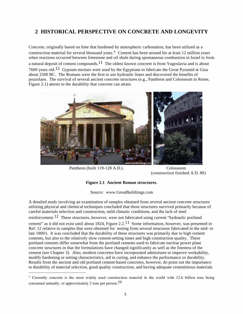
Concrete, originally based on lime that hardened by atmospheric carbonation, has been utilized as a construction material for several thousand years.∗ Cement has been around for at least 12 million years when reactions occurred between limestone and oil shale during spontaneous combustion in Israel to form a natural deposit of cement compounds.11 The oldest known concrete is from Yugoslavia and is about 7600 years old.12 Gypsum mortars were used by the Egyptians to fabricate the Great Pyramid at Giza about 2500 BC. The Romans were the first to use hydraulic limes and discovered the benefits of pozzolans. The survival of several ancient concrete structures (e.g., Pantheon and Colosseum in Rome, Figure 2.1) attests to the durability that concrete can attain.
Pantheon (built 119-128 A.D.). Colosseum (construction finished A.D. 80)
Figure 2.1 Ancient Roman structures.
Source: www.GreatBuildiings.com
A detailed study involving an examination of samples obtained from several ancient concrete structures utilizing physical and chemical techniques concluded that these structures survived primarily because of careful materials selection and construction, mild climatic conditions, and the lack of steel reinforcement.12 These structures, however, were not fabricated using current “hydraulic portland cement” as it did not exist until about 1824, Figure 2.2.11 Some information, however, was presented in Ref. 12 relative to samples that were obtained for testing from several structures fabricated in the mid- to late 1800's. It was concluded that the durability of these structures was primarily due to high cement contents, but also to the relatively slow cement-setting times and high construction quality. These portland cements differ somewhat from the portland cements used to fabricate nuclear power plant concrete structures in that the formulations have changed significantly as well as the fineness of the cement (see Chapter 3). Also, modern concretes have incorporated admixtures to improve workability, modify hardening or setting characteristics, aid in curing, and enhance the performance or durability. Results from the ancient and old portland cement-based concretes, however, do point out the importance to durability of material selection, good quality construction, and having adequate cementitious materials ∗ Currently concrete is the most widely used construction material in the world with 12.6 billion tons being consumed annually, or approximately 2 tons per person.10

6
to produce dense concretes resistant to penetration by deleterious agents.
Figure 2.2 Concrete historical timeline.
Source: Adaptation of http://matse1.mse.uiuc.deu/~tw/concrete/time.html.
Surveys of reported errors involving general civil engineering concrete structures in North American and Europe13,14 concluded that when errors occurred they were almost always the result of faulty construction or design deficiencies.* Errors due to construction were generally discovered during construction. On a more current note, the American Society of Civil Engineers has assigned a “D grade” to the nation’s infrastructure and estimates that $1.6 trillion in total investment is required over the next five years to fix the problems.15 Numerous reports in the literature16 have referenced the premature deterioration of “present-day” concretes, especially in structures that have been exposed to industrial and urban environments, de-icing chemicals, and sea water. In most cases the concrete degradation was associated with corrosion of steel reinforcement. A comprehensive review of the durability of field concrete during the twentieth century17 has concluded that the modern portland cement concrete mixtures, usually designed for high strength at an early age, are prone to cracking. Interconnections between the macrocracks, microcracks, and voids in the concrete thus provide pathways for the penetration of water
* A limitation of the North American study was that the information presented was strongly biased toward errors that escaped detection until revealed by the structure and thus did not present a true picture of the error-detection process of the review check system. Also, the survey favored those structures and serviceability characteristics that revealed themselves in a short period of time and thus does not represent the actual incidences of concrete degradation.13

7
and harmful ions necessary to initiate concrete degradation that has reduced the concrete durability. Also since the 1930’s (see next chapter) the tricalcium silicate content and fineness of ordinary portland cement has been steadily increasing. Present-day concrete mixtures contain higher quantities of the more-reactive portland cement in order to produce the required higher strengths at early age, but this can result in higher thermal contraction and increased drying shrinkage. Consequently the concrete cracks to lose its watertightness which can result in reduced durability. Surveys of the performance of nuclear power plant concrete structures have also been completed.18-20 A survey questionnaire has been sent to U.S. utilities to obtain information related to in-service inspection procedures, incidences of degradation, and repair procedures that have been utilized with respect to the concrete structures.21 Responses to the survey questionnaire, provided by slightly less than half the commercial nuclear power plants in the U.S., indicated that the majority of problems associated with the concrete structures were the result of design and construction errors, generally initiated during construction, and have been corrected.+ This indicates the overall effectiveness of quality control/quality assurance programs at nuclear power plants in ensuring that the factors associated with production of good quality concrete have been adequately addressed (e.g., material selection, batching, mixing, placing, and curing).22
+ Appendix B provides more detailed information.

8

9
3 MATERIALS OF CONSTRUCTION Nuclear safety-related concrete structures are composed of several constituents that, in concert, perform multiple functions (e.g., load-carrying capacity, radiation shielding, and leak tightness). Primarily, these constituents can include the following material systems: concrete, conventional steel reinforcement, prestressing steel, and steel liner plate. The quality of these materials is established through regulations, qualification tests, and certification followed by checking throughout construction. Table 3.1 indicates the influence of the design mechanical properties of these materials on the dimensioning of the structural components.23 More detailed information on materials of construction to that provided below is available elsewhere.18,24-26
Table 3.1 Relationship between mechanical properties and section dimensions
Mechanical Property Concrete Thickness
Steel Reinforcement
Post-Tensioning System
Liner
Concrete Compressive strength X X A Inital modulus X X X Delayed modulus X X Shrinkage, creep X X Steel Reinforcement Yield stress X Post-Tensioning System Ultimate tensile stress X Yield stress X Relaxation value X Friction factors X Liner Yield stress X
A = anchorage zone. Source: fib Task Group 1.3 Containment Structures, “Nuclear Containments – State-of-the-Art Report,” Bulletin 13, International Federation for Structural Concrete (fib), Federal Institute of Technology, Lausanne, Switzerland, 2001. 3.1 Concrete Concrete is a composite material consisting of a binder (cement paste) and a filler of fine or fine and coarse aggregate particles that combine to form a synthetic conglomerate. Cement is a mixture of compounds made by grinding crushed limestone, clay, sand, and iron ore together to form a homogeneous powder that is then heated at very high temperatures ranging from 1400 to 1600˚C to form a clinker.25 After the clinker cools, it is ground and mixed with a small amount of gypsum to regulate setting and facilitate placement. This produces the general-purpose portland cement that is mixed with water to produce cement paste that binds the aggregate particles together.+
+ Current generation cements have higher C3S contents and are ground finer than previous cements. The current generation cements attain almost all their compressive strength within a 28-day period whereas the previous generation cements continue to gain strength after 28 days.8,27

10
Portland cements are composed primarily of four chemical compounds: tricalcium silicate (C3S), dicalcium silicate (C2S), tricalcium aluminate (C3A), and tetracalcium aluminoferrite (C4AF). The type of portland cement produced (e.g., general purpose, moderate sulfate resistance and heat of hydration, high early strength, low heat of hydration, and sulfate resistant) depends on the relative amounts of the four basic chemical compounds and fineness (high early strength). The calcium silicate hydrates (C-S-H) constitute about 75% the mass. The C-S-H gel structure is made up of three types of groups that contribute to bonds across surfaces or in the interlayer of partly crystallized tobermorite material: calcium ions, siloxanes, and water molecules. Bonding of the water within the layers (gel water) with other groups via hydrogen bonds determines the strength, stiffness, and creep properties of the cement paste. There are also a number of alternative cementing agents that have been used in conjunction with portland cement such as pulverized fly ash, ground granulated blast furnace slag, and silica fume. Fly ash is collected from the exhaust flow of furnaces burning finely ground coal and reacts with calcium hydroxide in the presence of water to form cement compounds consisting of calcium silicate hydrate. Ground granulated blast-furnace slag (GGBS) is a by-product of the iron-making process and is formed by taking the hot slag, rapidly chilling or quenching it, and grinding into a powder. When mixed with water in the presence of an alkaline environment provided by the portland cement, GGBS hydrates to form cementing compounds consisting of calcium silicate hydrate. Silica fume is the condensed vapor by-product of the ferro-silicon smelting process. Silica fume reacts with calcium hydroxide in the presence of water to form cementing compounds consisting of calcium silicate hydrate. High alumina cement,# consisting mainly of calcium aluminates, has been utilized as a cementitious material because of its rapid set and rapid strength gain characteristics and resistance to acidic environments, sea water, and sulfates. However, because under certain conditions of temperature and humidity the cement converts over time to a different hydrate having reduced volume (i.e., increased porosity and reduced strength), it is recommended that calcium aluminate cements not be used for structural applications (particularly in wet or humid conditions above 27˚C).28 Selection of the proper water content of concrete is critical since too much water reduces the concrete strength and if insufficient water is added the concrete will be unworkable. Hardening of concrete occurs as a result of hydration, which is a chemical reaction in which the major compounds in the cement form chemical bonds with water molecules and become hydrates. The hardened cement paste consists mainly of calcium silicate hydrates, calcium hydroxide, and lower proportions of calcium sulphoaluminate hydrate either as ettringite or monosulphate. About 20% of the hardened cement paste volume is calcium hydroxide. The pore solution is normally a saturated solution of calcium hydroxide within which high concentrations of potassium and sodium hydroxides are present. Proper curing of the concrete during this stage is essential as it affects the concrete’s durability, strength, water-tightness, abrasion resistance, volume stability, and resistance to freezing and thawing. Since cement is the most expensive ingredient in concrete, it is desirable to utilize the minimum amount necessary to produce the desired properties and characteristics. Aggregate typically occupies 60 to 75% of the volume of concrete∗ and therefore its characteristics strongly influences the chemical, physical, and thermal properties of concrete, its mix proportions, and economy. Aggregates thus are important with respect to the concrete durability. The aggregates come in various shapes, sizes, and material types ranging from fine sand particles to large coarse rocks. Selection of the aggregate material is determined in part by the desired characteristics of the concrete. Aggregate materials are available ranging from
# Several nuclear power plants have utilized high alumina cement to produce porous concrete subfoundations. Although some erosion of the cementitious materials has occurred in at least one plant, the amount of material removed has been insignificant and the plants are monitored for any signs of excessive settlement.29 ∗ The balance of the concrete mix generally consists of 10 to 15% cement, 15 to 20% water, and air (5 to 8% if entrained).

11
ultra-lightweight (e.g., vermiculite and perlite) to lightweight (e.g., expanded clay shale or slate-crushed brick) to normal weight (e.g., crushed limestone or river gravel) to heavy-weight (e.g., steel or iron shot). Sometimes chemical or mineral admixtures are added during the mixing process to enhance durability (air entrainment), improve workability (enhanced placement and compaction), modify hardening and setting characteristics, aid in curing, reduce heat evolution, or provide other property improvements.30 Basic concrete constituent materials are identified in Figure 3.1.
Figure 3.1 Basic concrete constituent materials
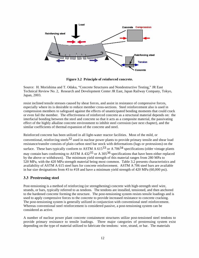
The concrete typically used in nuclear safety-related structures consists of Type II portland cement,25 fine aggregates (e.g., sand), water, various mineral or chemical admixtures for improving properties or performance of the concrete, and either normal-weight or heavy-weight coarse aggregate. Although eight types of portland cement are recognized by ASTM C 150,31 Type II portland cement typically has been used because of its improved sulfate resistance and reduced heat of hydration relative to the general purpose Type I portland cement. Both the water and fine and coarse aggregates are normally acquired from local sources and subjected to material characterization testing prior to use. Coarse aggregate can consist of gravel, crushed gravel, or crushed stone. Chemical (e.g., air-entraining or water-reducing) or mineral (e.g., fly ash or ground granulated blast furnace slag) admixtures have been utilized in many of the mixes to impart improved characteristics or performance. For those concrete structures in nuclear power plants that provide primary (biological) radiation shielding, heavy-weight, or dense aggregate materials, such as barites, limonites, magnetites, and ilmenites, may have been used to reduce the section thickness and meet attenuation requirements. The constituents are proportioned and mixed to develop portland cement concrete that has specific properties. Depending on the characteristics of the specific structure, the concrete mix may be adjusted to provide increased strength, higher durability, or better workability for placement. The hardened concrete typically provides the compressive load-carrying capacity for the structure. Specified concrete unconfined compressive strengths typically have ranged from 13 to 55 MPa, with 35 MPa being a typical value achieved at 28-days age. 3.2 Conventional steel reinforcement Concrete tensile strength is about one-tenth to one-fifth its compressive strength so concrete can not be relied upon to withstand very high tensile stresses. This limitation is overcome by embedding steel reinforcement in the concrete. The concrete and steel thus work in concert, Fig. 3.2. In addition to resisting tensile loads, the bonded steel reinforcement is used to control the extent and width of cracks,
12
Figure 3.2 Principle of reinforced concrete.
Source: H. Morishima and T. Odaka, “Concrete Structures and Nondestructive Testing,” JR East Technical Review No. 2, Research and Development Center JR East, Japan Railway Company, Tokyo, Japan, 2003. resist inclined tensile stresses caused by shear forces, and assist in resistance of compressive forces, especially where its is desirable to reduce member cross-sections. Steel reinforcement also is used in compression members to safeguard against the effects of unanticipated bending moments that could crack or even fail the member. The effectiveness of reinforced concrete as a structural material depends on: the interfacial bonding between the steel and concrete so that it acts as a composite material, the passivating effect of the highly alkaline concrete environment to inhibit steel corrosion (see next chapter), and the similar coefficients of thermal expansion of the concrete and steel. Reinforced concrete has been utilized in all light-water reactor facilities. Most of the mild, or conventional, reinforcing steels32 used in nuclear power plants to provide primary tensile and shear load resistance/transfer consists of plain carbon steel bar stock with deformations (lugs or protrusions) on the surface. These bars typically conform to ASTM A 61533 or A 70634 specifications (older vintage plants may contain bars conforming to ASTM A 43235 or A 30536 specifications that have been either replaced by the above or withdrawn). The minimum yield strength of this material ranges from 280 MPa to 520 MPa, with the 420 MPa strength material being most common. Table 3.2 presents characteristics and availability of ASTM A 615 steel bars for concrete reinforcement. ASTM A 706 steel bars are available in bar size designations from #3 to #18 and have a minimum yield strength of 420 MPa (60,000 psi). 3.3 Prestressing steel Post-tensioning is a method of reinforcing (or strengthening) concrete with high-strength steel wire, strands, or bars, typically referred to as tendons. The tendons are installed, tensioned, and then anchored to the hardened concrete forming the structure. The post-tensioning system resists tensile loadings and is used to apply compressive forces to the concrete to provide increased resistance to concrete cracking. The post-tensioning system is generally utilized in conjunction with conventional steel reinforcement. Whereas conventional steel reinforcement is considered passive, a post-tensioning system can be considered as active. A number of nuclear power plant concrete containment structures utilize post-tensioned steel tendons to provide primary resistance to tensile loadings. Three major categories of prestressing system exist depending on the type of material utilized to fabricate the tendons: wire, strand, or bar. The materials

13
Table 3.2 Characteristics and availability of ASTM A615 steel reinforcement for concrete.
ASTM A 615 Deformed and Plain Carbon-Steel Bars for Concrete Reinforcement Nominal Dimensions Availability Nominal Bar
Size Designation
Nominal Weight (lb/ft)
Diameter (in.)
Cross Sectional Area (in2)
Grade 40 (40,000 psia min. yield strength)
Grade 60 (60,000 psib min. yield strength)
Grade 75 (75,000 psic min. yield strength)
#3 0.376 0.375 0.11 X X #4 0.668 0.500 0.20 X X #5 1.043 0.625 0.31 X X #6 1.502 0.750 0.44 X X X #7 2.044 0.875 0.60 X X #8 2.670 1.000 0.79 X X #9 3.400 1.128 1.00 X X #10 4.303 1.270 1.27 X X #11 5.313 1.410 1.56 X X #14 7.65 1.693 2.25 X X #18 13.60 2.257 4.00 X X
a280 MPa; b420 MPa; c520 MPa. used to fabricate the tendons for these systems conform to ASTM specifications A 421,37 A 416,38 and A 722,39 respectively. Minimum tensile strengths range from 1620 to 1725 MPa for the A 421 material and 1725 to 1860 MPa for the A 416 material. The A 722 material has a minimum tensile strength of 1035 MPa. Typical nuclear power plant tendon systems group sufficient numbers of wires, strands, or bars to have minimum ultimate strengths ranging from 2,000 kN to 10,000 kN. The trend has been to increase the strength of the tendons to reduce the total number (e.g., in the early 1970’s the typical tendon had a capacity of 3,000 kN and since has progressed to capacities of 10,300 kN and 15,300 kN).23 The tendons are installed within preplaced ducts in the containment structure and post-tensioned from one or both ends after the concrete has achieved sufficient strength. After tensioning, the tendons are anchored by buttonheads, wedges, or nuts. Corrosion protection is provided by filling the ducts with wax or corrosion-inhibiting grease (unbonded), or portland cement grout (bonded). Supplemental conventional reinforcing is also used to minimize shrinkage or temperature effects and to provide local load-carrying capacity or load transfer. With the exception of Robinsion 2 (bar tendons) and Three Mile Island 2 (strand tendons), plants that have post-tensioned containments utilize unbonded tendons so that the tendons can be inspected and replaced (if necessary). Bellefonte and Ginna each have grouted tendons (rock anchors) to which tendons are attached. Figure 3.3 presents an example of a multistrand tendon for a general civil engineering application.
Figure 3.3 Example of a multistrand tendon. Source: www.vsl.net
14
3.4 Liner plate Leak tightness of reinforced and post-tensioned concrete containment vessels is provided by a steel liner plate. A typical liner is composed of steel plate stock less than 13 mm thick, joined by welding, and anchored to the concrete by studs (Nelson studs or similar conforming to ASTM A 10840), structural steel shapes, or other steel products. The drywell portions of BWR containments and PWR containments are typically lined with carbon steel (ASTM A 3632 or A 51641). The liners of LWR fuel pool structures typically consist of stainless steel (ASTM A 276,42 or A 30443). The liners of wetwells also have used carbon steel materials such as ASTM A 285,44 A 516,41 and A 537.45 Certain LWR facilities also have used carbon steel clad with stainless steel weld metal for liner members. Although the liner's primary function is to provide a leaktight barrier, it acts as part of the formwork during concrete placement and may be used in the support of internal piping/equipment. The liner is not considered to contribute to the strength of the structure.

15
4 AGING AND DURABILITY 4.1 Introduction Whether or not a concrete structure will degrade is a function of many factors including the constituent materials, its location (e.g., coastal or inland), climatic conditions (e.g., temperature and moisture), and the presence of external agents (e.g., sulfates and chemicals). When the concrete mix design and reinforcement cover meet the prescriptive requirements of standards and codes, and the concrete is properly mixed, placed, compacted and cured, durability problems attributable to concrete as a material are relatively rare. However, concrete may deteriorate as a result of violation of one of the previous items, inadequate design or construction practices, lack of maintenance, or because an inadequate concrete was specified.46 4.2 Design, Construction, and Maintenance Considerations Design errors that can lead to subsequent deterioration of concrete structures can be placed into two categories: inadequate structural design and lack of attention to details.47 Inadequate structural design occurs when the structure is exposed to a load greater than it is capable of carrying or it sustains greater strain than its strain capacity. Inadequate considerations of temperature change or concrete creep and accidental impact can also result in damage. Typical symptoms of inadequate design include spalling and cracking of concrete. Poor detailing of a structure may result in localized concentration of stresses that results in cracking, which in turn can permit water or chemicals to access the concrete; or ponding of water to produce saturated concrete. Poor detailing does not generally lead directly to concrete failure, but can contribute to the action of one of the other specific causes of concrete failure.47 Examples of inadequate structural design include: insufficient concrete cover over steel reinforcement, improper sizing and placement of steel reinforcement, inadequate section geometry, inadequate provision for drainage, abrupt changes in section, material incompatibility, and inadequate provision for deflection. Poor construction practices and negligence can result from not following specified procedures or carelessness. Poor construction practices do not lead directly to failure or deterioration of concrete but can cause defects that lead to concrete cracking. Examples of concrete cracks that can result from poor construction practices include: plastic shrinkage, plastic settlement, early thermal contraction, crazing, and long-term drying shrinkage. The resulting concrete cracking then can enhance the adverse impacts of mechanisms such as described in the next section and lead to concrete degradation. Poor construction practices and negligence is best addressed through adequate quality assurance/quality control in conjunction with an aggressive inspection program. Examples of poor construction practice include: adding additional water to concrete to facilitate placement or finishing, improper mixing and curing, improper consolidation, and improper location of steel reinforcement. Lack of knowledge about the importance of careful selection and specification of materials and use of admixtures can also result in durability issues. This can include improper cement contents, use of poor quality or contaminated aggregates, incorporation of additives that can produce corrosion such as calcium chloride accelerators, and incorrect water-cement ratios. Improper or inadequate maintenance can also contribute to the deterioration of concrete structures. Examples of inadequate maintenance include: moisture exposure and penetration caused by unrepaired cracks, improper application of coatings, and failure to clean drains and drain pathways.

16
4.3 Environmental Stressor Considerations The longevity, or long-term performance of safety-related concrete structures is primarily a function of the durability or propensity of these structures to withstand the potential effects of degradation. Table 4.1 presents a summary of the degradation factors that can potentially impact the performance of the basic constituents that comprise safety-related concrete structures in nuclear power plants (i.e., concrete, mild steel reinforcement, post-tensioning system, and liner/structural steel members). Also contained in the table is a listing of primary manifestations of each degradation factor. More detailed information to that summarized below is available elsewhere.48-53
Table 4.1 Primary degradation factors that can impact safety-related concrete structures
Material System Degradation Factor Primary Manifestation Physical processes Cracking Salt crystallization Freezing and thawing Abrasion/erosion/cavitation Thermal exposure/thermal cycling Irradiation Fatigue/vibration Settlement
Reduced durability Cracking/loss material Cracking/scaling/disintegration Section loss Cracking/spalling/strength loss Volume change/cracking Cracking Cracking/spalling/misalignment
Concrete
Chemical processes Efflorescence/leaching Sulfate attack Delayed ettringite formation Acids/bases Alkali-aggregate reactions Aggressive water Phosphate Biological attack
Increased porosity Volume change/cracking Volume change/cracking Disintegration/spalling/leaching Disintegration/cracking Disintegration/loss material Surface deposits Increased porosity/erosion
Mild steel reinforcement
Corrosion Elevated temperature Irradiation Fatigue
Concrete spalling/cracking/loss section Decreased strength Reduced ductility Bond loss
Post-tensioning Corrosion Elevated temperature Irradiation Fatigue Stress relaxation/end effects
Strength loss/reduced ductility Reduced strength Reduced ductility Concrete cracking Prestress force loss
Liner/structural steel
Corrosion Elevated temperature Irradiation Fatigue
Section loss Reduced strength Reduced ductility Cracking
4.3.1 Concrete Material Systems The durability of concrete materials can be limited as a result of adverse performance of its cement-paste matrix or aggregate constituents as a result of either physical or chemical processes. In practice, these processes may occur concurrently to reinforce each other. In nearly all physical and chemical processes influencing the durability of concrete structures, dominant factors involved include transport mechanisms

17
within the pores and cracks, and the presence of water. Transport mechanisms important in the consideration of durability of concrete include:54 • diffusion of gases, CO2, O2, and water vapor through empty pockets, microcracks and the interfaces between components; • diffusion of ions (e.g., chlorides and sulfates) in the concrete pore solution and dissolved gases; • permeation of water or aqueous solutions under hydraulic head (submerged concrete or water-control structures);55 and • capillary suction of water (water absorption) or aqueous solutions in empty or unsaturated capillaries. Transport characteristics, however, do not provide information on the rate or extent of reaction, or the total amount of substance reacting with the aggressive material, and therefore only provide an indication of a material’s durability.54 Table 4.2 provides an indication of the influence of moisture (relative humidity) on several deterioration processes in concrete.56
Table 4.2 Influence of moisture state on selected durability processes.
Relative severity of deterioration process* Risk of steel corrosion
Ambient relative humidity Carbonation
of concrete Frost attack on concrete
Chemical attack on concrete
In carbonated concrete
In chloride-rich concrete
Very low (<40%) 1 0 0 0 0† Low (40-60%) 3ˆ 0 0 1 1 Medium (60-80%) 2© 0 0 3 3 High (80-90%) 1 2 1 2 3 Saturated (>98%) 0 3 3 1 1 *0 = insignificant, 1 = slight risk, 2 = medium risk, 3 = high risk. †Corrosion risk in chloride-rich environments high if significant humidity variations. ˆFor 40-50% relative humidity, carbonation is medium. ©For 60-70 % relative humidity, carbonation is high. Source: Diagnosis of Deterioration in Concrete Structures – Identification of Defects, Evaluation and Development of Remedial Action, Technical Report No. 54, The Concrete Society, Century House, Berkshire, United Kingdom, 2000. Permission to use this copyrighted material is granted by CEB and Thomas Telford Services Ltd. 4.3.1.1 Physical Processes Physical attack involves the degradation of concrete due to external influences and generally involves cracking due to exceeding the tensile strength of the concrete, or loss of surface material. Load-induced cracking is not considered as an aging mechanism. Cracking Cracking occurs in virtually all concrete structures and, because of concrete’s inherently low tensile strength and lack of ductility, can never be totally eliminated. Cracks and crack patterns have different characteristics depending on the underlying cause. Cracks are significant from the standpoint that they can indicate major structural problems (active cracks); provide an important avenue for the ingress of hostile environments (active or dormant cracks); and may inhibit a component from meeting its performance requirements (active or dormant cracks) (e.g., diminished leaktightness or shielding

18
capacity). Figure 4.1a provides information on the types of cracks that can form in concrete structures7
and Figure 4.1b provides a description and appearance of several of the crack forms.57
Figure 4.1 Relationship between primary causes and types of cracks in concrete.
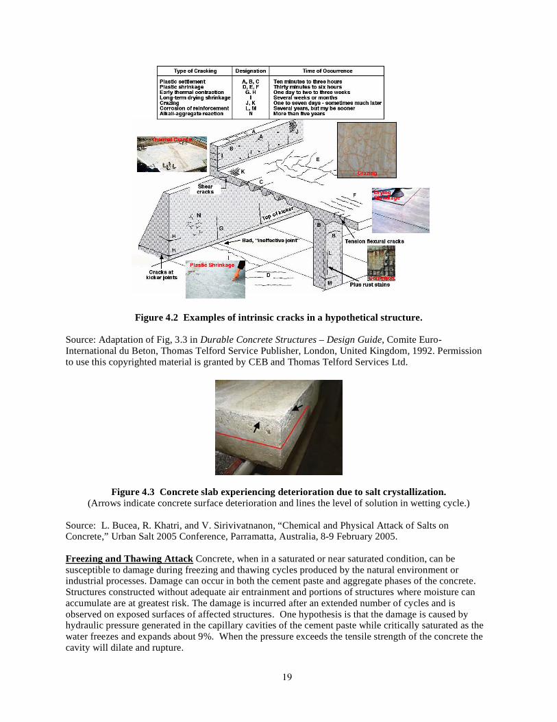
Source: (a) Durable Concrete Structures — Design Guide, Comite Euro-International de Beton, Thomas Telford Service Publisher, London, United Kingdom, 1989; (b) H.-U. Litzner and A. Baker, “Design of Concrete Structures for Durability and Strength to Eurocode 2,” Materials and Structures 32, pp. 323-330, June 1999. Permission to use this copyrighted material in Figure 4.1a is granted by CEB and Thomas Telford Services Ltd. Figure 4.2 presents examples of the most common types of intrinsic cracks that form in concrete as well as an indication of their potential time of occurrence.7,58 Reference 59 provides additional information on cracking and its classification with respect to damage.+ Salt Crystallization Physical salt attack is caused by the movement of salt solution by capillary action through the concrete and subsequent crystallization through drying. The process is repeated through cycles of wetting and drying. Figure 4.3 presents a concrete slab after one-year exposure to cyclic wetting and drying in sulfate solutions.60 Crystallization and recrystallization of certain salts (e.g., NaCl, CaS04, and NaS04) can generate expansive forces that result in the physical breakdown of the concrete. The mechanism is somewhat similar to freezing and thawing of water in concrete. Structures in contact with fluctuating water levels or in contact with ground waters containing large quantities of dissolved salts are susceptible to this type of deterioration. Above ground level the moisture is drawn to the concrete surface where it evaporates leaving crystals of salt growing in the near surface pores. The result is an area of deterioration just above ground level. The problem of salt crystallization is minimized for low permeability concretes and where sealers or barriers have been effectively applied to prevent water ingress or subsequent evaporation.
+ Additional information on cracking is presented in Section 4.3.2.1 and Appendix C.
19
Figure 4.2 Examples of intrinsic cracks in a hypothetical structure.
Source: Adaptation of Fig, 3.3 in Durable Concrete Structures – Design Guide, Comite Euro-International du Beton, Thomas Telford Service Publisher, London, United Kingdom, 1992. Permission to use this copyrighted material is granted by CEB and Thomas Telford Services Ltd.
Figure 4.3 Concrete slab experiencing deterioration due to salt crystallization. (Arrows indicate concrete surface deterioration and lines the level of solution in wetting cycle.)
Source: L. Bucea, R. Khatri, and V. Sirivivatnanon, “Chemical and Physical Attack of Salts on Concrete,” Urban Salt 2005 Conference, Parramatta, Australia, 8-9 February 2005. Freezing and Thawing Attack Concrete, when in a saturated or near saturated condition, can be susceptible to damage during freezing and thawing cycles produced by the natural environment or industrial processes. Damage can occur in both the cement paste and aggregate phases of the concrete. Structures constructed without adequate air entrainment and portions of structures where moisture can accumulate are at greatest risk. The damage is incurred after an extended number of cycles and is observed on exposed surfaces of affected structures. One hypothesis is that the damage is caused by hydraulic pressure generated in the capillary cavities of the cement paste while critically saturated as the water freezes and expands about 9%. When the pressure exceeds the tensile strength of the concrete the cavity will dilate and rupture.
20
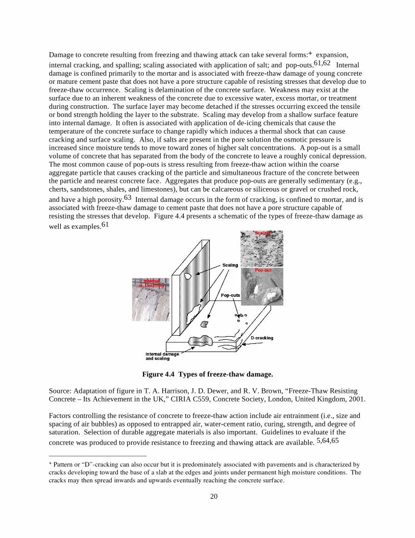
Damage to concrete resulting from freezing and thawing attack can take several forms:+ expansion, internal cracking, and spalling; scaling associated with application of salt; and pop-outs.61,62 Internal damage is confined primarily to the mortar and is associated with freeze-thaw damage of young concrete or mature cement paste that does not have a pore structure capable of resisting stresses that develop due to freeze-thaw occurrence. Scaling is delamination of the concrete surface. Weakness may exist at the surface due to an inherent weakness of the concrete due to excessive water, excess mortar, or treatment during construction. The surface layer may become detached if the stresses occurring exceed the tensile or bond strength holding the layer to the substrate. Scaling may develop from a shallow surface feature into internal damage. It often is associated with application of de-icing chemicals that cause the temperature of the concrete surface to change rapidly which induces a thermal shock that can cause cracking and surface scaling. Also, if salts are present in the pore solution the osmotic pressure is increased since moisture tends to move toward zones of higher salt concentrations. A pop-out is a small volume of concrete that has separated from the body of the concrete to leave a roughly conical depression. The most common cause of pop-outs is stress resulting from freeze-thaw action within the coarse aggregate particle that causes cracking of the particle and simultaneous fracture of the concrete between the particle and nearest concrete face. Aggregates that produce pop-outs are generally sedimentary (e.g., cherts, sandstones, shales, and limestones), but can be calcareous or siliceous or gravel or crushed rock, and have a high porosity.63 Internal damage occurs in the form of cracking, is confined to mortar, and is associated with freeze-thaw damage to cement paste that does not have a pore structure capable of resisting the stresses that develop. Figure 4.4 presents a schematic of the types of freeze-thaw damage as well as examples.61
Figure 4.4 Types of freeze-thaw damage.
Source: Adaptation of figure in T. A. Harrison, J. D. Dewer, and R. V. Brown, “Freeze-Thaw Resisting Concrete – Its Achievement in the UK,” CIRIA C559, Concrete Society, London, United Kingdom, 2001. Factors controlling the resistance of concrete to freeze-thaw action include air entrainment (i.e., size and spacing of air bubbles) as opposed to entrapped air, water-cement ratio, curing, strength, and degree of saturation. Selection of durable aggregate materials is also important. Guidelines to evaluate if the concrete was produced to provide resistance to freezing and thawing attack are available. 5,64,65
+ Pattern or “D”-cracking can also occur but it is predominately associated with pavements and is characterized by cracks developing toward the base of a slab at the edges and joints under permanent high moisture conditions. The cracks may then spread inwards and upwards eventually reaching the concrete surface.

21
Abrasion/Erosion/Cavitation Progressive loss of material at the concrete surface can occur due to abrasion, erosion, or cavitation. Abrasion generally refers to dry attrition due to rubbing or grinding of aggregate or other debris on the concrete surface, while erosion is normally used to describe wear by the abrasive action of fluids containing solid particles in suspension. Mechanical abrasion is usually characterized by long shallow grooves in the concrete surface and spalling along monolithic joints. Concrete surfaces abraded by water-borne debris are generally smooth and may contain localized depressions. Cavitation is the formation of bubbles or cavities in a liquid. In hydraulic structures, the liquid is water, and the cavities are filled with water vapor and air. The cavities form where the local pressure drops to a value that will cause the water to vaporize at the prevailing water temperature. Formation of these cavities is usually triggered by concrete surface irregularities that are subjected to high-velocity water flow. Cavitation bubbles will grow and travel with the flowing water to an area where the pressure field will cause collapse. When a bubble collapses or implodes close to or against a solid surface, an extremely high pressure is generated, which acts on an infinitesimal area of the surface for a very short time. A succession of these high-energy impacts will damage almost any solid material.66 Figure 4.5 presents examples of concrete abrasion-erosion. 66,67
Figure 4.5 Abrasion-erosion of concrete: (a) abrasion-erosion damage in a concrete stilling basin and (b) erosion of conventional concrete.
Sources: (a) Guide to Concrete Repair, U. S. Department of the Interior, Bureau of Reclamation,Technical Services, Denver, Colorado. 1996; (b) J. E. McDonald, “An Evaluation of Materials for Repair of Erosion Damage in Hydraulic Structures,” High-Performance Materials and Systems Research Program, U.S. Army Corps of Engineers, Waterways Experiment Station, Vicksburg, Mississippi, 1980. Resistance of concrete to abrasion and erosion is dependent on the quality of the concrete (low porosity, high strength) and in particular the aggregate particles used in the mix. While good quality concrete may show good resistance to abrasion and erosion, it may still suffer severe loss of surface material due to cavitation. The best way to guard against the effects of cavitation is to eliminate the cause(s) of cavitation. Reference 68 provides additional information on the effects of erosion on concrete structures. Thermal Exposure/Thermal Cycling Under elevated-temperature exposure, portland cement paste experiences physical and chemical changes that contribute to development of shrinkage, transient creep, and changes in strength. Key material features of hydrated portland cement paste affecting the properties of concrete at elevated temperature are its moisture state (i.e., sealed or unsealed), chemical structure (i.e., loss of chemically bound water from the C-S-H in the unsealed condition, CaO/SiO2 ratio of the hydrate in the sealed condition, and amount of Ca(OH)2 crystals in sealed or unsealed conditions), and physical structure (i.e., total pore volume including cracks, average pore size, and amorphous/crystalline structure of solid).69
22
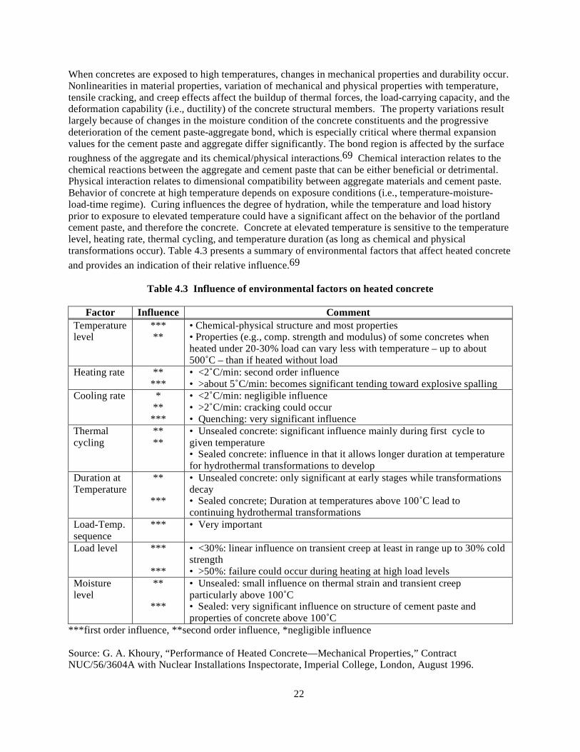
When concretes are exposed to high temperatures, changes in mechanical properties and durability occur. Nonlinearities in material properties, variation of mechanical and physical properties with temperature, tensile cracking, and creep effects affect the buildup of thermal forces, the load-carrying capacity, and the deformation capability (i.e., ductility) of the concrete structural members. The property variations result largely because of changes in the moisture condition of the concrete constituents and the progressive deterioration of the cement paste-aggregate bond, which is especially critical where thermal expansion values for the cement paste and aggregate differ significantly. The bond region is affected by the surface roughness of the aggregate and its chemical/physical interactions.69 Chemical interaction relates to the chemical reactions between the aggregate and cement paste that can be either beneficial or detrimental. Physical interaction relates to dimensional compatibility between aggregate materials and cement paste. Behavior of concrete at high temperature depends on exposure conditions (i.e., temperature-moisture-load-time regime). Curing influences the degree of hydration, while the temperature and load history prior to exposure to elevated temperature could have a significant affect on the behavior of the portland cement paste, and therefore the concrete. Concrete at elevated temperature is sensitive to the temperature level, heating rate, thermal cycling, and temperature duration (as long as chemical and physical transformations occur). Table 4.3 presents a summary of environmental factors that affect heated concrete and provides an indication of their relative influence.69
Table 4.3 Influence of environmental factors on heated concrete
Factor Influence Comment Temperature level
*** **
• Chemical-physical structure and most properties • Properties (e.g., comp. strength and modulus) of some concretes when heated under 20-30% load can vary less with temperature – up to about 500˚C – than if heated without load
Heating rate ** ***
• <2˚C/min: second order influence • >about 5˚C/min: becomes significant tending toward explosive spalling
Cooling rate * ** ***
• <2˚C/min: negligible influence • >2˚C/min: cracking could occur • Quenching: very significant influence
Thermal cycling
** **
• Unsealed concrete: significant influence mainly during first cycle to given temperature • Sealed concrete: influence in that it allows longer duration at temperature for hydrothermal transformations to develop
Duration at Temperature
**
***
• Unsealed concrete: only significant at early stages while transformations decay • Sealed concrete; Duration at temperatures above 100˚C lead to continuing hydrothermal transformations
Load-Temp. sequence
*** • Very important
Load level ***
***
• <30%: linear influence on transient creep at least in range up to 30% cold strength • >50%: failure could occur during heating at high load levels
Moisture level
**
***
• Unsealed: small influence on thermal strain and transient creep particularly above 100˚C • Sealed: very significant influence on structure of cement paste and properties of concrete above 100˚C
***first order influence, **second order influence, *negligible influence Source: G. A. Khoury, “Performance of Heated Concrete—Mechanical Properties,” Contract NUC/56/3604A with Nuclear Installations Inspectorate, Imperial College, London, August 1996.

23
A good summary of the degradation reactions that occur in Portland cement concrete is provided in Ref. 70. Upon first heating, substantial water evaporation occurs from the larger pores close to the concrete surface. Then, from 100°C onward, the evaporation proceeds at a faster rate with water being expelled from concrete near the surface as a result of above-atmospheric vapor pressure (i.e., steam flow). At 120°C the expulsion of water physically bound in the smaller pores, or chemically combined, initiates and continues up to about 500°C where the process is essentially complete. From 30°C to 300°C, in conjunction with evaporation, dehydration of the hardened cement paste occurs (first stage) with the maximum rate of dehydration occurring at about 180°C [Tobermorite gel is stable up to a temperature of 150°C (Ref. 71)]. In the temperature range from 450°C to 550°C there is decomposition of the portlandite [i.e., Ca(OH)2 → CaO + H2O)]. At 570°C the α → β inversion of quartz takes place with the transformation being endothermic and reversible. A further process of decomposition of the hardened cement paste takes place between 600°C and 700°C with the decomposition of the calcium-silicate-hydrate phases and formation of β-C2S. Between 600°C and 900°C the limestone begins to undergo decarbonation (i.e., CaCO3 → CaO + CO2). The rate of decomposition and the temperature at which it occurs are not only dependent on temperature and pressure, but also on the content of SiO2 present in the limestone. Above 1200°C and up to 1300°C, some components of the concrete begin to melt. Above 1300°C to 1400°C concrete exists in the form of a melt. Apparently liquifaction of the concrete commences with melting of the hardened cement paste followed by melting of the aggregates.72-74 The melting points of aggregates vary greatly. At 1060°C basalt is at the lower limit of all types of rock, with quartzite not melting below 1700°C.75 The response of concrete in terms of strength loss has been divided into three ranges: 20 to 400°C, 400 to 800°C, and above 800°C.76 In the first range, it was noted that normal strength concretes (<50 MPa) exhibit a slight loss of strength (~15%), whereas higher strength concretes (80 to 100 MPa) maintain their strengths. In the second range, both concretes lose most of their original strength, especially above 600°C. It is within this range that dehydration of the calcium-silicate-hydrate gel is most significant. Above 800°C only a small fraction of the original concrete strength remains. As some aggregates in concrete change color at elevated temperatures (e.g., sedimentary and metamorphic),∗,77 the color changes can be used to estimate the temperature reached.+ It has been indicated that up to 300°C the concrete color will be normal, its condition unaffected, with surface crazing around 290°C; from 300 to 600°C the concrete will be pink to red and apparently sound, but its strength will be significantly reduced; from 600 to 900°C the concrete will be gray to buff, and weak and friable; and above 900°C it will have a buff color (limestone becomes white) with little to no strength.79,80 The extent of color change varies with type of fine and coarse aggregate. Knowing the magnitude of thermal exposure, a rough estimate of the residual mechanical properties of concrete can be made. Because concrete’s in situ compressive strength generally exceeds design requirements, the modest strength reductions resulting from temperature exposures up to 300°C often can be tolerated. Figure 4.6 presents the effect of temperature on the residual compressive strength# of several unsealed ordinary concretes made with various normal weight aggregate materials and tested at room temperature after heat treatment.81 Table 4.4 presents additional information on upper and lower limits for ordinary concretes that were unsealed during heating.81 However, applicability of information such as presented in the above figure and table need to evaluated for each concrete because a concrete’s residual strength after elevated temperature exposure depends on a number of factors such as the temperature attained, type
∗ It should be noted that not all aggregates (e.g., igneous) exhibit color changes as a function of temperature. + Other methods for indicating the magnitude of concrete thermal exposure include differential thermal analysis, X-ray diffraction, thermoluminescence test, and thin-section petrography.78 # Residual ratio (%) = 100 x (value after heating)/(value before heating).

24
and porosity of aggregate, rate of heating, permeability, use of pozzolans, moisture state, mix proportions, and loading and sealing conditions during heating.
Figure 4.6 Effect of temperature on residual compressive strength: unsealed specimens.
Source: R. Blundell, C. Diamond, and R. G. Browne, “The Properties of Concrete Subjected to Elevated Temperature,” CIRIA Underwater Engineering Group, Technical Note No. 9, Concrete Society, London, United Kingdom, 1976.
Table 4.4 Residual ratios for compressive strength, tensile strength, and modulus of elasticity of ordinary concrete at elevated temperature: unsealed specimens.
Residual ratio (%)*
Compressive strength Tensile strength Elastic modulus Temp- erature
(˚C) Lower limit
Upper limit
Average Lower limit
Upper limit
Average Lower limit
Upper limit
Average
20 100 100 100 100 100 100 100 100 100 50 70 95 85 65 75 70 70 95 85 90 65 90 80 65 80 75 70 85 80 100 65 90 80 70 80 75 65 90 75 200 85 110 100 60 85 70 50 70 60 300 70 100 85 50 70 60 40 60 50 400 55 95 75 35 55 45 30 55 40
Source: R. Blundell, C. Diamond, and R. G. Browne, “The Properties of Concrete Subjected to Elevated Temperature,” CIRIA Underwater Engineering Group, Technical Note No. 9, Concrete Society, London, United Kingdom, 1976. In addition to potential reductions in strength and modulus of elasticity, thermal exposure of concrete can result in cracking, or when the rate of heating is high and concrete permeability low, surface spalling can occur. Elevated temperatures diminish the bond between concrete and steel reinforcement.82-84 Elevated temperatures also are important in that they affect the volume change and creep of concrete.85

25
Thermal cycling, even at relatively low temperatures (i.e., 65°C), can have deleterious effects on concrete's mechanical properties (i.e., compressive, tensile and bond strengths, and modulus of elasticity are reduced).86 Most reinforced concrete structures are subjected to thermal cycling due to daily temperature fluctuations and are designed accordingly (i.e., inclusion of steel reinforcement). At higher temperatures (200 to 300°C), the first thermal cycle causes the largest percentage of damage, with the extent of damage markedly dependent on aggregate type and is associated with loss of bond between the aggregate and matrix.87 Thermal cycles also can become important if the deformation of the structure resulting from the temperature variations is constrained. Additional information on the effects of elevated temperature on concrete materials and structures is available.88,89 Irradiation Irradiation in the form of either fast and thermal neutrons emitted by the reactor core or gamma rays produced as a result of capture of neutrons by members (particularly steel) in contact with concrete can affect the concrete. Changes in the properties of concrete appear to depend primarily on the behavior of the concrete aggregate that can undergo a volume change when exposed to radiation.90 The fast neutrons are mainly responsible for the considerable growth, caused by atomic displacements, that has been measured in certain aggregate (e.g., flint). Quartz aggregates that contain crystals with covalent bonding should be more affected by radiation than calcareous aggregates that contain crystals with ionic bonding.91 Furthermore, when nuclear radiation is attenuated or absorbed in the concrete almost all the absorbed radiation is converted into heat. Nuclear heating occurs as a result of energy introduced into the concrete as the neutrons or gamma radiation interact with the molecules within the concrete material. The heat generated may have detrimental effects on the physical, mechanical, and nuclear properties of the concrete. Reference 92 indicates that nuclear heating is negligible for incident energy fluxes less than 1010 MeV/cm2 per s. Determination of whether any deterioration that may occur in concrete properties is due to radiation damage or thermal effects can be difficult. Prolonged exposure of concrete to irradiation can result in decreases in tensile and compressive strengths and modulus of elasticity. Figure 4.7 presents a summary of the effects of neutron radiation on the compressive strength and modulus of elasticity of several concretes.90 Results in the literature90 indicate that: (1) for some concretes, neutron radiation of more than1 x 1019 neutrons/cm2 or 1010 rads of dose for
Figure 4.7 Effect of neutron radiation on concrete compressive strength and modulus of elasticity relative to unirradiated and unheated control specimen results.
Source: H. K. Hilsdorf et al., The Effects of Nuclear Radiation on the Mechanical Properties of Concrete, ACI SP-55, Douglas McHenry International Symposium on Concrete and Concrete Structures, American Concrete Institute, Farmington Hills, Michigan, 1978.

26
gamma radiation may cause a reduction in compressive strength; (2) tensile strength of concrete is significantly reduced at neutron fluences exceeding 1019 n/cm2 with the decrease of tensile strength caused by neutron radiation more pronounced than the decrease of compressive strength; (3) resistance of concrete to neutron radiation apparently depends on the type of neutrons (slow or fast) involved, but the effect is not clarified; (4) resistance of concrete to neutron radiation depends on mix proportions, type of cement, and type of aggregate; (5) the effect of gamma radiation on concrete's mechanical properties requires clarification; (6) the deterioration of concrete properties associated with a temperature rise resulting from irradiation is relatively minor; (7) coefficients of thermal expansion and conductivity of irradiated concrete differ little from those of temperature-exposed concrete; (8) when exposed to neutron irradiation, the modulus of elasticity of concrete decreases with increasing neutron fluence; (9) creep of concrete is not affected by low-level radiation exposure, but for high levels of exposure creep probably would increase with exposure because of the effects of irradiation on the concrete's tensile and compressive strengths;+ (10) for some concretes, neutron radiation with a fluence of more than 1 x 10¹⁹ neutrons/cm2 can cause a marked increase in volume; (11) generally, concrete’s irradiation resistance increases as the irradiation resistance of the aggregate increases; and (12) irradiation has little effect on shielding properties of concrete beyond moisture loss caused by a temperature increase. Furthermore, there is an indication that nuclear radiation can significantly increase the reactivity of silica-rich aggregates to alkali (i.e., alkali-silica reaction).102 Results from an investigation of the effect of γ-irradiation on the strength of a nuclear power plant concrete indicate that for a dose up to 6 x 10⁵ Gy the compressive, splitting-tensile, and flexural strength of concrete decreased with dose, reaching a reduction of about 10%, 5%, and 5%, respectively, at the maximum dose.103 It was noted in the reference that interaction of concrete with irradiation generated a succession of chemical reactions starting with radiolysis of water and terminating in formation of calcite crystals that decrease both the size of pore space and the strength of the concrete. Section III, Division 2 of the American Society of Mechanical Engineers Pressure Vessel and Piping Code gives an allowable radiation exposure level of 10 x 1020 nvt.104 The British Specification for Prestressed Concrete Pressure Vessels for Nuclear Reactors105 states that the maximum permissible neutron dose is controlled by the effects of irradiation on concrete properties, and the effects are considered to be insignificant for doses up to 0.5 x 10¹⁸ neutrons/cm2. Table 2.7 from Ref. 106 provides data for estimated radiation environments at the outside surface of light-water reactor pressure vessels for a 1000 MW(e) plant operating at a capacity factor of 80%. These results indicate that radiation levels may approach the limits provided above in a concrete primary shield wall after 40 years of operation (32 equivalent full-power years). However, these values are upper limits and probably higher than would be experienced because of the attenuating effects that would occur due to the presence of air gaps, insulation, etc., that could be positioned between the pressure vessel and concrete structures. More detailed information on the interaction of radiation and concrete is available in Ref. 91. Fatigue/Vibration Concrete structures subjected to fluctuations in loading, temperature, or moisture content (that are not large enough to cause failure in a single application) can be damaged by fatigue. Fatigue damage initiates as microcracks in the cement paste, proximate to the large aggregate particles, reinforcing steel, or stress risers (e.g., defects). Upon continued or reversed load application, these microcracks may propagate to form structurally significant cracks that can expose the concrete and reinforcing steel to hostile environments or produce increased deflections. Ultimate failure of a concrete structure in fatigue will occur as a result of excessive cracking, excessive deflections, or brittle fracture. As concrete ages and gains strength, for a given stress level the cycles to failure will increase. If the concrete is reinforced or prestressed, properties of the steel tend to control structural performance since + Gamma rays produce radiolysis of water in cement paste that can affect concrete's creep and shrinkage behavior to a limited extent and also result in evolution of gas.
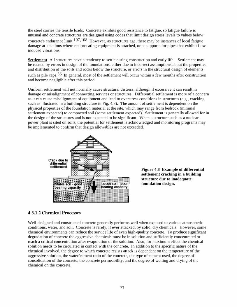
27
the steel carries the tensile loads. Concrete exhibits good resistance to fatigue, so fatigue failure is unusual and concrete structures are designed using codes that limit design stress levels to values below concrete's endurance limit.107,108 However, as structures age, there may be instances of local fatigue damage at locations where reciprocating equipment is attached, or at supports for pipes that exhibit flow-induced vibrations. Settlement All structures have a tendency to settle during construction and early life. Settlement may be caused by errors in design of the foundations, either due to incorrect assumptions about the properties and distribution of the soils and rocks below the structure, or errors in the structural design of elements such as pile caps.56 In general, most of the settlement will occur within a few months after construction and become negligible after this period. Uniform settlement will not normally cause structural distress, although if excessive it can result in damage or misalignment of connecting services or structures. Differential settlement is more of a concern as it can cause misalignment of equipment and lead to overstress conditions in structures (e.g., cracking such as illustrated in a building structure in Fig. 4.8). The amount of settlement is dependent on the physical properties of the foundation material at the site, which may range from bedrock (minimal settlement expected) to compacted soil (some settlement expected). Settlement is generally allowed for in the design of the structures and is not expected to be significant. When a structure such as a nuclear power plant is sited on soils, the potential for settlement is acknowledged and monitoring programs may be implemented to confirm that design allowables are not exceeded.
Figure 4.8 Example of differential settlement cracking in a building structure due to inadequate foundation design.
4.3.1.2 Chemical Processes Well-designed and constructed concrete generally performs well when exposed to various atmospheric conditions, water, and soil. Concrete is rarely, if ever attacked, by solid, dry chemicals. However, some chemical environments can reduce the service life of even high-quality concrete. To produce significant degradation of concrete the aggressive chemicals must be in solution and sufficiently concentrated or reach a critical concentration after evaporation of the solution. Also, for maximum effect the chemical solution needs to be circulated in contact with the concrete. In addition to the specific nature of the chemical involved, the degree to which concrete resists attack is dependent on the temperature of the aggressive solution, the water/cement ratio of the concrete, the type of cement used, the degree of consolidation of the concrete, the concrete permeability, and the degree of wetting and drying of the chemical on the concrete.

28
Chemical attack involves the alteration of concrete through chemical reaction with either the cement paste or coarse aggregate, or embedded steel reinforcement.** Generally, the attack occurs on the exposed surface region of the concrete (cover concrete), but with the presence of cracks or prolonged exposure, chemical attack can affect entire structural cross sections. Chemical causes of deterioration can be grouped into three categories: (1) hydrolysis of cement paste components by soft water; (2) cation exchange reactions between aggressive fluids and the cement paste; and (3) reactions leading to formation of expansion products.109 Figure 4.9 presents a summary of the types of chemical reactions responsible for concrete deterioration and the detrimental effects that can occur.110 Chemical attack of concrete may occur in several different forms as highlighted in the following sections.
Figure 4.9 Types of chemical reactions responsible for concrete deterioration.
Source: P. K. Mehta and B. C. Gerwick, Jr., "Cracking-Corrosion Interaction in Concrete Exposed to Marine Environment," pp. 45–51 in Concrete International 4(10), American Concrete Institute, Farmington Hills, Michigan, October 1982. Permission to use this copyrighted material is granted by the author. Efflorescence and Leaching Efflorescence is a crystalline deposit of salts, usually white, that occurs on or near the surface of concrete following the percolation of a fluid (e.g., water) through the material, either intermittently or continuously, or when an exposed surface is alternately wetted and dried. It forms due to crystallization of the dissolved salts, usually calcium, sodium, or potassium carbonate, as a result of evaporation of the fluid or interaction with carbon dioxide in the atmosphere. Occasionally efflorescence may be a symptom of chemical reactions such as sulfate attack or it may indicate leaks in a water-retaining structure or undesired leakage of moisture through a structure. To establish that damage has occurred, it is essential to demonstrate that deleterious reactions have occurred in the interior of the ** Corrosion of embedded steel reinforcement due to carbonation of the concrete or the action of chloride ions is covered under the section addressing mild steel reinforcement.

29
concrete or at its surfaces in contact with sulfates in the surrounding soil.111 Typically, however, efflorescence is primarily an aesthetic problem rather than affecting the concrete mechanical properties or durability. In rare cases, excessive efflorescence deposits can occur within the surface pores of the concrete causing expansion that may disrupt the surface.112 Figure 4.10 presents an example of efflorescence in a water structure.
Figure 4.10 Efflorescence in water structure.
Source: Dam Safety: Problems in Concrete Materials, Fact Sheet 03-06, Indiana Department of Natural Resources, Division of Water, Indianapolis, August 23, 2003. Leaching of cementitious materials mainly involves the transportation of ions from the interior of the material through its pore system outwards into the surroundings. In the leaching process solid compounds in the concrete are dissolved by water that has penetrated and are transported away either by diffusion based on the concentration gradients or convection through the flow of water. Pure water that contains little or no calcium ions, or acidic ground water present in the form of dissolved carbon dioxide gas, carbonic acid, or bicarbonate ion, tends to hydrolyze or dissolve the alkali oxides and calcium-containing products. Water with a pH less than 12.5 is aggressive toward concrete since it destabilizes the cementitious hydration products. The rate of leaching is dependent on the amount of dissolved salts contained in the percolating fluid, rate of permeation of the fluid through the cement paste matrix, and temperature. Extensive leaching causes an increase in porosity and permeability thus lowering the strength of the concrete and making it more vulnerable to hostile environments (e.g., water saturation and frost damage, or chloride penetration and corrosion of embedded steel). Figure 4.11 shows a schematic of different types of leaching found in concrete hydraulic structures.113 Examples of leaching in a concrete dam and a tendon gallery of a nuclear power plant are shown in Figure 4.12. Concrete leaching is basically of three types: (1) leaching at free surfaces of the concrete, (2) leaching from the interior of concrete, and (3) leaching at surfaces of cracks in concrete.114 Figure 4.13 presents conceptual models for each of the leaching types. Of these types, (a) is generally of little importance, (b) is serious and can result in serious damage, and (c) is difficult to deal with and complicated to assess. Concretes produced using low water-cement ratios, adequate cement content, and proper compaction and curing are most resistant to leaching.
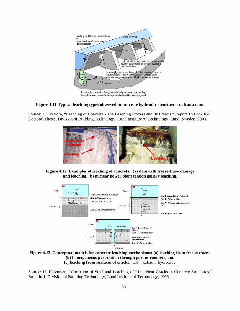
30
Figure 4.11 Typical leaching types observed in concrete hydraulic structures such as a dam.
Source: T. Ekström, “Leaching of Concrete - The Leaching Process and Its Effects,” Report TVBM-1020, Doctoral Thesis, Division of Building Technology, Lund Institute of Technology, Lund, Sweden, 2003.
Figure 4.12 Examples of leaching of concrete: (a) dam with freeze-thaw damage and leaching, (b) nuclear power plant tendon gallery leaching.
Figure 4.13 Conceptual models for concrete leaching mechanisms: (a) leaching from free surfaces,
(b) homogeneous percolation through porous concrete, and (c) leaching from surfaces of cracks. CH = calcium hydroxide.
Source: U. Halvorsen, “Corrosion of Steel and Leaching of Lime Near Cracks in Concrete Structures,” Bulletin 1, Division of Building Technology, Lund Institute of Technology, 1966.

31
Sulfate Attack All sulfates are potentially harmful to concrete. Sulfate attack of concrete is caused by exposure of concrete products or structures to an excessive amount of sulfate from internal or external sources. Internal sulfate attack results when a soluble source of sulfates is incorporated into the concrete at the time of mixing through the hydraulic cement, presence of natural gypsum or pyrite in the aggregate, and admixtures. External sulfate attack is most common and typically occurs when water containing dissolved sulfates penetrates the concrete. Magnesium, sodium, calcium, and potassium sulfates present in soils, ground water, and sea water react with the calcium hydroxide and if enough water is present, result in expansion and irregular cracking of the concrete that can lead to progressive loss of strength and mass. The degree of sulfate attack depends on water penetration, the sulfate salt and its concentration and type, the means by which the salt develops in the concrete (e.g., is it rising and drying causing crystallization), and the chemistry of the binder present in the concrete. Sulfate attack of hardened concrete generally appears in two forms: expansive formation of ettringite and gypsum in the hardened concrete causing cracking and exfoliation, and softening and dissolution of the hydrated cementing compounds due to direct attack on these compounds by sulfate or by their decomposition when calcium hydroxide reacts with the sulfates and is removed.47 The end result of sulfate attack can be excessive expansion, delamination, cracking, and loss of strength. Figure 4.14 illustrates the mechanism of sulfate (sodium) attack and presents an example of cracking resulting from sulfate attack. It has been reported that at a concentration of about 0.2% sulfate content in ground water concrete may suffer sulfate attack, magnesium sulfate can be more aggressive than sodium sulfate, and there are three key chemical reactions between sulfate ions and hardened cement pastes: (1) recrystallization of ettringite, (2) formation of calcium sulfoaluminate (ettringite), and (3) decalcification of the main cementitious phase (calcium silicate hydrate).115
Figure 4.14 Concrete cracking due to sulfate attack: (a) mechanism, (b) example of concrete cracking due to sulfate attack.
Source: Diagnosis of Deterioration in Concrete Structures – Identification of Defects, Evaluation and Development of Remedial Action, Technical Report No. 54, The Concrete Society, Century House, Berkshire, United Kingdom, 2000. Guidelines for assessing the potential degree of severity of expected attacked have been established by organizations such as the American Concrete Institute (ACI),5 Canadian Standards Association (CSA),116 Deutsches Institute für Normung (DIN),117 and British Standards.118 Table 4.5 provides current ACI Building Code requirements for concrete exposed to sulfate-containing solutions.5
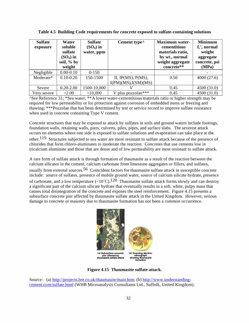
32
Table 4.5 Building Code requirements for concrete exposed to sulfate-containing solutions
Sulfate exposure
Water soluble sulfate
(SO4) in soil, % by
weight
Sulfate (SO4) in
water, ppm
Cement type^ Maximum water-cementitious
materials ratio, by wt., normal
weight aggregate concrete**
Minimum fc’, normal
weight aggregate
concrete, psi (MPa)
Negligible 0.00-0.10 0-150 - - - Moderate* 0.10-0.20 150-1500 II, IP(MS), P(MS),
I(PM)(MS),I(SM)(MS) 0.50 4000 (27.6)
Severe 0.20-2.00 1500-10,000 V 0.45 4500 (31.0) Very severe >2.00 >10,000 V plus pozzolan*** 0.45 4500 (31.0)
^See Reference 31; *Sea water; **A lower water-cementitious materials ratio or higher strength may be required for low permeability or for protection against corrosion of embedded items or freezing and thawing; ***Pozzolan that has been determined by test or service record to improve sulfate resistance when used in concrete containing Type V cement. Concrete structures that may be exposed to attack by sulfates in soils and ground waters include footings, foundation walls, retaining walls, piers, culverts, piles, pipes, and surface slabs. The severest attack occurs on elements where one side is exposed to sulfate solutions and evaporation can take place at the other.119 Structures subjected to sea water are more resistant to sulfate attack because of the presence of chlorides that form chloro-aluminates to moderate the reaction. Concretes that use cements low in tricalcium aluminate and those that are dense and of low permeability are most resistant to sulfate attack. A rare form of sulfate attack is through formation of thaumasite as a result of the reaction between the calcium silicates in the cement, calcium carbonate from limestone aggregates or fillers, and sulfates, usually from external sources.56 Coincident factors for thaumasite sulfate attack in susceptible concrete include: source of sulfates, presence of mobile ground water, source of calcium silicate hydrate, presence of carbonate, and a low temperature (<10˚C).120 Thaumasite sulfate attack forms slowly and can destroy a significant part of the calcium silicate hydrate that eventually results in a soft, white, pulpy mass that causes total disintegration of the concrete and exposes the steel reinforcement. Figure 4.15 presents a subsurface concrete pier affected by thaumasite sulfate attack in the United Kingdom. However, serious damage to concrete or masonry due to thaumasite formation has not been a common occurrence.
Figure 4.15 Thaumasite sulfate attack.
Source: (a) http://projects.bre.co.uk/thaumasite/main.htm; (b) http://www.understanding-cement.com/sulfate.html (WHB Microanalysis Consultants Ltd., Suffolk, United Kingdom).
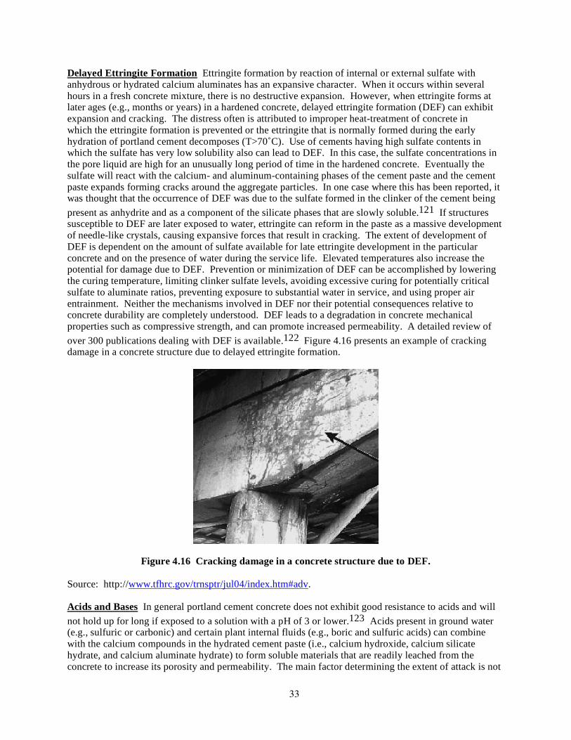
33
Delayed Ettringite Formation Ettringite formation by reaction of internal or external sulfate with anhydrous or hydrated calcium aluminates has an expansive character. When it occurs within several hours in a fresh concrete mixture, there is no destructive expansion. However, when ettringite forms at later ages (e.g., months or years) in a hardened concrete, delayed ettringite formation (DEF) can exhibit expansion and cracking. The distress often is attributed to improper heat-treatment of concrete in which the ettringite formation is prevented or the ettringite that is normally formed during the early hydration of portland cement decomposes (T>70˚C). Use of cements having high sulfate contents in which the sulfate has very low solubility also can lead to DEF. In this case, the sulfate concentrations in the pore liquid are high for an unusually long period of time in the hardened concrete. Eventually the sulfate will react with the calcium- and aluminum-containing phases of the cement paste and the cement paste expands forming cracks around the aggregate particles. In one case where this has been reported, it was thought that the occurrence of DEF was due to the sulfate formed in the clinker of the cement being present as anhydrite and as a component of the silicate phases that are slowly soluble.121 If structures susceptible to DEF are later exposed to water, ettringite can reform in the paste as a massive development of needle-like crystals, causing expansive forces that result in cracking. The extent of development of DEF is dependent on the amount of sulfate available for late ettringite development in the particular concrete and on the presence of water during the service life. Elevated temperatures also increase the potential for damage due to DEF. Prevention or minimization of DEF can be accomplished by lowering the curing temperature, limiting clinker sulfate levels, avoiding excessive curing for potentially critical sulfate to aluminate ratios, preventing exposure to substantial water in service, and using proper air entrainment. Neither the mechanisms involved in DEF nor their potential consequences relative to concrete durability are completely understood. DEF leads to a degradation in concrete mechanical properties such as compressive strength, and can promote increased permeability. A detailed review of over 300 publications dealing with DEF is available.122 Figure 4.16 presents an example of cracking damage in a concrete structure due to delayed ettringite formation.
Figure 4.16 Cracking damage in a concrete structure due to DEF.
Source: http://www.tfhrc.gov/trnsptr/jul04/index.htm#adv. Acids and Bases In general portland cement concrete does not exhibit good resistance to acids and will not hold up for long if exposed to a solution with a pH of 3 or lower.123 Acids present in ground water (e.g., sulfuric or carbonic) and certain plant internal fluids (e.g., boric and sulfuric acids) can combine with the calcium compounds in the hydrated cement paste (i.e., calcium hydroxide, calcium silicate hydrate, and calcium aluminate hydrate) to form soluble materials that are readily leached from the concrete to increase its porosity and permeability. The main factor determining the extent of attack is not

34
so much the aggressiveness of the attacking acid, but more the solubility of the resulting calcium salt. The rate of deterioration is also accelerated if the aggressive chemical solution is flowing. Since under acid attack there is a conversion of the hardened cement, the concrete permeability is not as important as for other types of chemical attack (e.g., leaching and sulfate attack). Nitric, hydrochloric, and sulfuric acids are very aggressive as their calcium salts are readily soluble and removed from the acid front. Organic acids such as formic, acetic, and lactic are also corrosive to portland cement concrete. Other acids such as phosphoric, carbonic, tannic, and humic are less harmful as their calcium salts have low solubility and inhibit the attack by blocking the pathways within the concrete. Oxalic acids have negligible affect on portland cement concretes. Carbonic, humic, and sulfuric acids are the acids most commonly encountered by concrete since they are found in natural ground waters. Visual examination of concrete undergoing acid attack will show disintegration of the concrete in the form of loss of cement paste and aggregate from the matrix. Due to the large buffering capacity of concrete and the relatively small amount of acid contained in rain, acid rain will convert only an insignificant amount of the concrete.57 Acid rain is even a smaller threat to nuclear power plant structures than general civil engineering concrete structures because of their massive cross sections. Surface coatings and a dense concrete with a low water-cement ratio provide improved resistance to acid environments. Figure 4.17 illustrates the mechanism of acid attack and presents an example of acid attack on a concrete wall.
Figure 4.17 Surface loss due to acid attack: (a) mechanism, (b) example of acid attack on concrete wall.
Source: (a) Diagnosis of Deterioration in Concrete Structures – Identification of Defects, Evaluation and Development of Remedial Action, Technical Report No. 54, The Concrete Society, Century House, Berkshire, United Kingdom, 2000; (b) Guide to Concrete Repair, U.S. Department of the Interior, Bureau of Reclamation, Technical Services, Denver, Colorado. 1996. As hydrated cement paste is an alkaline material, high quality concretes made with chemically stable aggregates normally are resistant to bases. However, sodium and potassium hydroxides in high concentrations (> 20%) can cause concrete to disintegrate. Under mild chemical attack, a dense concrete with low water-cement ratio may provide suitable resistance. As corrosive chemicals can attack concrete only in the presence of water, designs to minimize attack by acids and bases generally involve the use of protective barrier systems. Table 4.6 presents a listing of the reactivity with concrete of various chemicals that may be found in nuclear power plants or the surrounding environment. References 124 and 125 present additional information on the effect of chemicals on concrete.
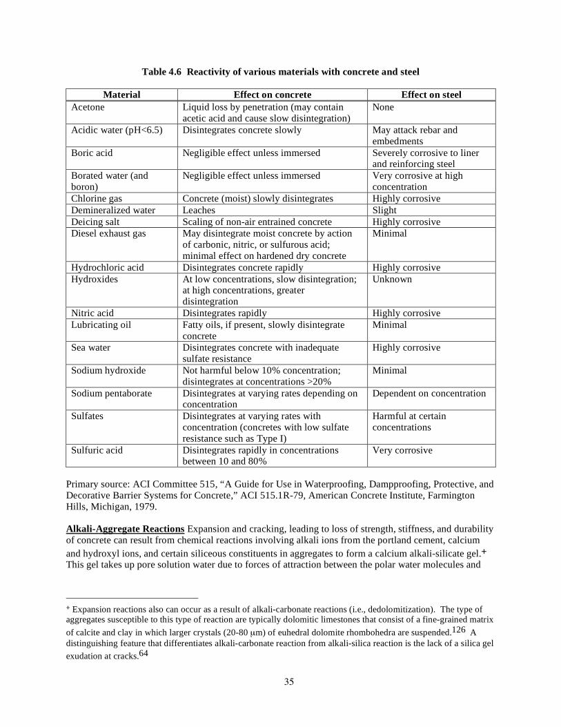
35
Table 4.6 Reactivity of various materials with concrete and steel
Material Effect on concrete Effect on steel Acetone Liquid loss by penetration (may contain
acetic acid and cause slow disintegration) None
Acidic water (pH<6.5) Disintegrates concrete slowly May attack rebar and embedments
Boric acid Negligible effect unless immersed Severely corrosive to liner and reinforcing steel
Borated water (and boron)
Negligible effect unless immersed Very corrosive at high concentration
Chlorine gas Concrete (moist) slowly disintegrates Highly corrosive Demineralized water Leaches Slight Deicing salt Scaling of non-air entrained concrete Highly corrosive Diesel exhaust gas May disintegrate moist concrete by action
of carbonic, nitric, or sulfurous acid; minimal effect on hardened dry concrete
Minimal
Hydrochloric acid Disintegrates concrete rapidly Highly corrosive Hydroxides At low concentrations, slow disintegration;
at high concentrations, greater disintegration
Unknown
Nitric acid Disintegrates rapidly Highly corrosive Lubricating oil Fatty oils, if present, slowly disintegrate
concrete Minimal
Sea water Disintegrates concrete with inadequate sulfate resistance
Highly corrosive
Sodium hydroxide Not harmful below 10% concentration; disintegrates at concentrations >20%
Minimal
Sodium pentaborate Disintegrates at varying rates depending on concentration
Dependent on concentration
Sulfates Disintegrates at varying rates with concentration (concretes with low sulfate resistance such as Type I)
Harmful at certain concentrations
Sulfuric acid Disintegrates rapidly in concentrations between 10 and 80%
Very corrosive
Primary source: ACI Committee 515, “A Guide for Use in Waterproofing, Dampproofing, Protective, and Decorative Barrier Systems for Concrete,” ACI 515.1R-79, American Concrete Institute, Farmington Hills, Michigan, 1979. Alkali-Aggregate Reactions Expansion and cracking, leading to loss of strength, stiffness, and durability of concrete can result from chemical reactions involving alkali ions from the portland cement, calcium and hydroxyl ions, and certain siliceous constituents in aggregates to form a calcium alkali-silicate gel.+ This gel takes up pore solution water due to forces of attraction between the polar water molecules and
+ Expansion reactions also can occur as a result of alkali-carbonate reactions (i.e., dedolomitization). The type of aggregates susceptible to this type of reaction are typically dolomitic limestones that consist of a fine-grained matrix of calcite and clay in which larger crystals (20-80 µm) of euhedral dolomite rhombohedra are suspended.126 A distinguishing feature that differentiates alkali-carbonate reaction from alkali-silica reaction is the lack of a silica gel exudation at cracks.64

36
the alkali-silicate ions and expands, which can disrupt the concrete.∗ Figure 4.18 presents the mechanism of alkali-silica reaction (ASR) and the gel resulting from alkali-aggregate reaction that causes expansion
Figure 4.18 Concrete cracking due to alkali-silica reaction: (a) mechanism, (b) resulting gel that causes expansion and cracking, (c) polished section of concrete showing chert
particle with extensive internal cracks extending from aggregate as noted by arrows.
Source: (a) Diagnosis of Deterioration in Concrete Structures – Identification of Defects, Evaluation and Development of Remedial Action, Technical Report No. 54, The Concrete Society, Century House, Berkshire, United Kingdom, 2000; (b) Guide to Concrete Repair, U.S. Department of the Interior, Bureau of Reclamation, Technical Services, Denver, Colorado. 1996; (c) www.understanding-cement.com/alkali-silica.html (WHB Microanalysis Consultants Ltd., Suffolk, United Kingdom). and cracking. The primary factors influencing alkali-silica reactions include the aggregate reactivity (i.e., amount and grain size of reactive aggregate), alkali and calcium concentrations in concrete pore water, cement content (i.e., alkali content), and presence of water. Aggregates throughout the U.S. and the world have been found to be reactive. To date, no incidences of ASR-related damage have been identified in U.S. nuclear power plant concrete structures. The potential for ASR to occur in newly constructed nuclear power plant concrete structures needs to be addressed, however, because current generation portland cements have increased alkali contents that may result in reactivity of aggregates that were not reactive in the past, and the availability of good quality aggregate materials is becoming limited in many areas of the U.S. The most reactive forms of aggregate are strained quartz, amorphous silica, cryptocrystalline quartz, chalcedony, and chert.128 Table 4.7 presents a listing of some of the potentially harmful reactive minerals, rock, and synthetic materials that may cause deterioration of concrete when the reactive component is present in amounts as small as 1%.129 In general, aggregates containing crystalline ∗ It has been noted that potentially damaging tensile stresses from 4,100 kPa to 11,000 kPa can develop within the cement paste matrix.127

37
Table 4.7 Some potentially harmful reactive minerals, rock, and synthetic materials
Alkali-silica reactive substances* Alkali-carbonate reactive substances**
Andesites Opal Calcitic dolomites Argillites Opaline shales Dolomitic limestones Certain siliceous limestones and dolomites
Phylites Fine-grained dolomites
Chalcedonic cherts Quartzites Chalcedony Quartzoses Cherts Rhyolitic Cristobalite Schists Dacitic Siliceous shales Glassy or cryptocrystalline volcanics
Strained quartz and certain other forms of quartz
Granite gneiss Synthetic and natural siliceous glass Graywackes Tridymite Metagraywackes
*Several of rocks listed (e.g., granite, gneiss, and certain quartz formations) react very slowly and may not show evidence of any harmful degree of reactivity until concrete age is >20 years. **Only certain sources of these materials have shown reactivity. Source: Appendix B to Concrete Material and Methods of Concrete Construction, CAN/CSA -A23.1, Canadian Standards Association, Toronto, 2000.
silica are stable and those with amorphous or very fine-grained silica are reactive.129 Although alkali-silica reactions typically occur within 5 to 10 years of construction, deterioration has not occurred in some structures until 15 or even 25 or more years following construction. The delay in exhibiting deterioration indicates that there may be less reactive forms of silica that can eventually cause deterioration.62 In rare circumstances, ASR expansions can be as much as 2 – 3%.130 Crack widths up to 15 mm and crack depths to 300 mm have been observed in the field.131 Since structures in service are stressed and cracked, expansive strains from ASR of 0.10 to 0.20% superimposed over load-induced cracks can lead to structural distortion and displacements. However, full-scale load tests on ASR-affected concrete structures and components indicate that visually severe ASR cracking can be deceptive and that the expansion and cracking that ASR induces may not lead to an unacceptably adverse effect on the structural performance of reinforced and prestressed concrete members.132 No concrete structure or part of a structure has been reported to have collapsed due to ASR.132 Some of the most significant reported problems resulting from ASR are misalignment of structures, displacement of equipment, and spalling at joints. The effects of ASR on engineering properties often cannot be generalized since both the rate of expansion and the total expansion depend on the reactive aggregate, cement type, cement content, constraint, and environment. For expansive strains of 0.5 to 1.5%, loss in compressive strength can vary from 40 to 60%, whereas loss of tensile strength can be as high as 65 to 80%, with loss of elastic modulus from 60 to 80%.130 Reference 133 provides some guidance to indicate the effects of ASR expansion on the residual compressive strength of concrete (lower bound) [i.e., for restrained expansions (µm/m) due to ASR of 0.5, 1.0, 2.5, and 5.0%, the percentages of residual compressive strengths are 95, 80, 60, and 60, respectively]. In tests of lapped beams in which the effects of ASR on performance were evaluated, it was found that ASR causes a reduction in bond strength (up to 22% for these tests) and a significant reduction in the fatigue life.134 Other investigators using lapped beams have shown reductions in bond

38
strength in excess of 50% with losses for smooth bars greater than for ribbed bars.135,136 Prestress developed by the ASR expansion can enhance the shear strength and stiffness of beams.137 Figure 4.19 presents examples of alkali-aggregate reactions in concrete structures.
Figure 4.19 Examples of concrete cracking: (a) alkali-silica reaction in bridge pier, (b) alkali-carbonate reaction in sidewalk with exudation of joint material.
Source: (a) Portland Cement Association, Skokie, Ill. (www.cement.org/tech/cct_durability.asp), (b) P. E. Gratten-Bellew and L. Mitchell, “Preventing Concrete Deterioration Due to Alkali-Aggregate Reactivity,” Concrete Technology Update, No. 52, National Research Council of Canada, Ottawa, March 2002. Visual detection of alkali-silica reactions is difficult in the early stages due to the fineness of the cracks and may go unrecognized for years. If the concrete member is unrestrained, visible concrete damage starts with small surface cracks exhibiting an irregular pattern (or map cracking). When the expansive forces are restrained (e.g., by reinforcement), the cracking pattern will be modified as the expansion will develop in the direction of least constraint (i.e., parallel surface crack patterns propagating inward from the surface for slabs and cracking parallel to compression forces in columns or prestressed members). Pop-outs and glassy appearing seepage of varying composition can appear as a result of alkali-silica reactions. Furthermore, it is quite common that once cracking has developed, the cracks can allow access to the interior of the concrete to enable some other deleterious mechanisms to operate (e.g., leaching by percolating water accompanied by precipitation of calcium carbonate on surfaces, steel reinforcement corrosion, and freeze-thaw attack). It has been shown that alkali-silica reactions occurring in concretes contaminated with NaCl increases the risk of chloride-induced corrosion of steel reinforcement.138
The best approach to prevention of alkali-aggregate reactions is to avoid using aggregates that are known or suspected of being reactive. Procedures for testing aggregates for reactivity and for minimizing the effects when reactive aggregates are used are available.139 In new concrete designs the use of low-alkali portland cement (with an alkali content less than 0.6% Na2O equivalent) has been successfully used on slightly to moderately reactive aggregates.127 International codes or standards limit the alkali content+ of the concrete accounting for the cement factor and other internal sources of alkali.140 The addition of
+ The alkali content to prevent alkali-carbonate reaction is lower than that required for prevention of alkali-silica reaction.140

39
fly ash has been shown to control ASR,∗ but its effectiveness is highly dependent on the type of fly ash, its alkali content, chemical composition, and dosage rate.138 Other types of finely divided minerals such as silica fume, ground granulated blast furnace slag, and natural pozzolans can also be effective in preventing ASR.140 Also, addition of ASR-inhibiting compounds (e.g., lithium hydroxide) has been shown to be effective on highly reactive aggregates.141,142 Aggressive Water Attack# Concrete in service may be exposed to aggressive waters, with the most common deleterious ion being sulfate.143 In other waters, acids and chemical by-products from industrial processes may be present. Some locations have sea water or brackish water in contact with concrete. Most sea waters have a pH of 7.5 to 8.4, are fairly uniform in chemical composition, contain about 3.5% soluble salts by weight, with Na+ and Cl- having the highest ionic concentrations, but Mg2+ and SO4
2- are also present.109 Reaction of magnesium sulfate with the cement hydration products leads to formation of ettringite, calcium sulfate, and insoluble magnesium hydroxide (brucite) that reduces the rate of attack of dense concrete. The rate of attack is further reduced by the formation of aragonite (calcium carbonate) which forms more readily in the tidal zone than the surface layers of a completely immersed element.46 Concrete exposed to a marine environment may deteriorate as a result of combined effects of chemical action of sea water constituents on cement hydration products, alkali-aggregate expansion if reactive aggregates are present, crystallization pressure of salts within concrete if one face of the structure is subject to wetting and others to drying conditions, frost action in cold climates, corrosion of embedded steel reinforcement, and physical erosion due to wave action or floating objects. Figure 4.20 presents a diagrammatic representation of deterioration of concrete exposed to sea water as well as examples of sea water attack.
Figure 4.20 Sea water attack of concrete: (a) mechanism, (b) and (c) examples of attack.
Source: www.cemexphilippines.com
∗ Pozzolans are not effective in controlling alkali-carbonate reaction.127,140 #Leaching of calcium hydroxide from concrete by flowing water was discussed earlier.

40
Phosphate Ion Attack Thermodynamic studies indicate that phosphate could replace calcium hydroxide with calcium hydroxyapatite [Ca5(PO4)3OH].144 The data show that in an ordinary portland cement system the formation of calcium hydroxyapatite is capable of replacing free calcium hydroxide (Portlandite) and competes successfully for calcium in aluminosilicate matrices. In order to determine if this can lead to degradation of concrete through expansive reactions, a literature review and small–scale laboratory investigation was conducted. Results of the literature review indicated that no harmful interactions of phosphate and cementitious materials occur unless the phosphates are present in the form of phosphoric acid.144 The laboratory study involved casting cement paste cubes and prisms that were cured in solutions of calcium hydroxide (control), magnesium phosphate, and sodium phosphate. Periodically specimens were removed from each of the curing solutions and measured, weighed, evaluated for compressive strength, and examined by x-ray diffraction or scanning-electron microscope methods. After 12-months exposure to the curing solutions, no evidence of degradation due to exposure to either of the highly-concentrated phosphate solutions has been observed.145 Biological Attack Growth on concrete structures may lead to mechanical deterioration caused by lichen, moss, algae, and roots of plants and trees penetrating into the concrete at cracks and weak spots, resulting in bursting forces causing increased cracking and deterioration. Such growth can also retain water on the concrete surface leading to a high moisture content with subsequent increased risk of deterioration due to freezing. Microgrowth may cause chemical attack by development of humic acid that can dissolve the cement paste.57 Formation of capillaries within the concrete during the hydration process and the capillary action of water provide a means for penetration of microorganisms into concrete. The metabolism of microorganisms results in the excretion of sulfuric or nitric acid that can contribute substantially to the degradation of cementitious materials. A number of organisms are capable of causing the dissolution of concrete through leaching of calcium and other alkaline binding materials.146 These organisms are known to cause serious damage to sewer lines, buildings, and monuments. In environments where reduced sulfur compounds are present, such as sewers, the production of sulfuric acid by sulfur oxidizing bacteria (thiobacilli) forms a corrosive layer that causes extensive cement degradation. The sulfuric acid reacts with the free lime [Ca(OH)2] to form gypsum (CaSO4•2H2O) that produces a corroding layer on the concrete surface that penetrates into the concrete. The newly formed gypsum crystals react with calcium aluminate in the cement to produce ettringite that further contributes to the degradation of concrete by increasing the internal pressure leading to formation of cracks that, in turn, provide a larger surface area for the corrosion process.147 In environments where reduced sulfur compounds are limiting, such as on buildings, nitric acid-producing nitrifying bacteria have been found to play a role in concrete degradation.148 The action of nitric acid on the calcareous components of concrete results in the production of calcium nitrate (soluble salt) that is either lost from the concrete resulting in formation of corrosion pits or remains to add salt to the pore water. The sulfate-reducing bacteria are primarily responsible for degradation of concrete above ground and the nitrifying bacteria for degradation below ground.149 Microbes have extremely diverse modes of metabolism, are natural inhabitants of soil, and can survive extreme environments such as the inner wall of a geothermal cooling tower.150 Concrete can also be corroded by gluconic, malic, and oxalic acids produced by fermentative bacteria that are natural soil inhabitants.151 Figure 4.21 presents examples of biological attack of concrete and Table 4.8 provides a summary of the effects of microorganisms on building materials.

41
Figure 4.21 Concrete biological attack: (a) algae growth on outside wall of house, (b) biogenic sulfuric acid attack in sewer system, (c) decaying concrete floor in flooded cellar. Source: (a) and (c) G. Morton, “Things that Go Rot in the Night – A Review of Biodegradation,” Microbiology Today 30 (21), August 2003; (b) F-J. Hofmann, K. Hormann, M. Schmidt, and E. Wagner, “Concrete with Greater Resistance to Acid and to Biogenic Sulfuric Acid Corrosion,” Betonwerk+Fertigteil – Technik 4, pp. 2-8, 1997.
Table 4.8 Effects of microorganisms on building materials.
Activity Effect(s) Material Microorganism Physical presence Discoloration
Retention of water All All
Physical presence Increased growth of heterotrophic organisms
Any clean surface Algae, photosynthetic bacteria
Hydrolytic enzymes Breakdown of components; Degradation of short-chain additives
Wood, painted surfaces, polymers. Mortar, concrete
Fungi, bacteria; Filamentous fungi
Filamentous growth Disaggregation of material
Stone, concrete, mortar, wood
Fungi, actinomycetes, cyanobacteria, algae
Acid production Corrosion Stone, concrete, mortar
Fungi, bacteria
Mobilization of ions Weakening and dissolution
Stone, concrete, mortar
All
Chelation of constituent ions
Weakening and dissolution
Stone, concrete, mortar
Organic acid producers (e.g., fungi)
Uptake of H+ ions by cells
Alkaline corrosion Stone Algae, cyanobacteria
Release of polyols (e.g., glycerol, polysaccharides)
Disruption of layered silicates
Siliceous stone All
Source: C. Gaylarde, M. Ribas Silva, and Th. Warscheid, “Microbial Impact on Building Materials: An Overview,” Materials and Structures 36, pp. 342-352, June 2003.
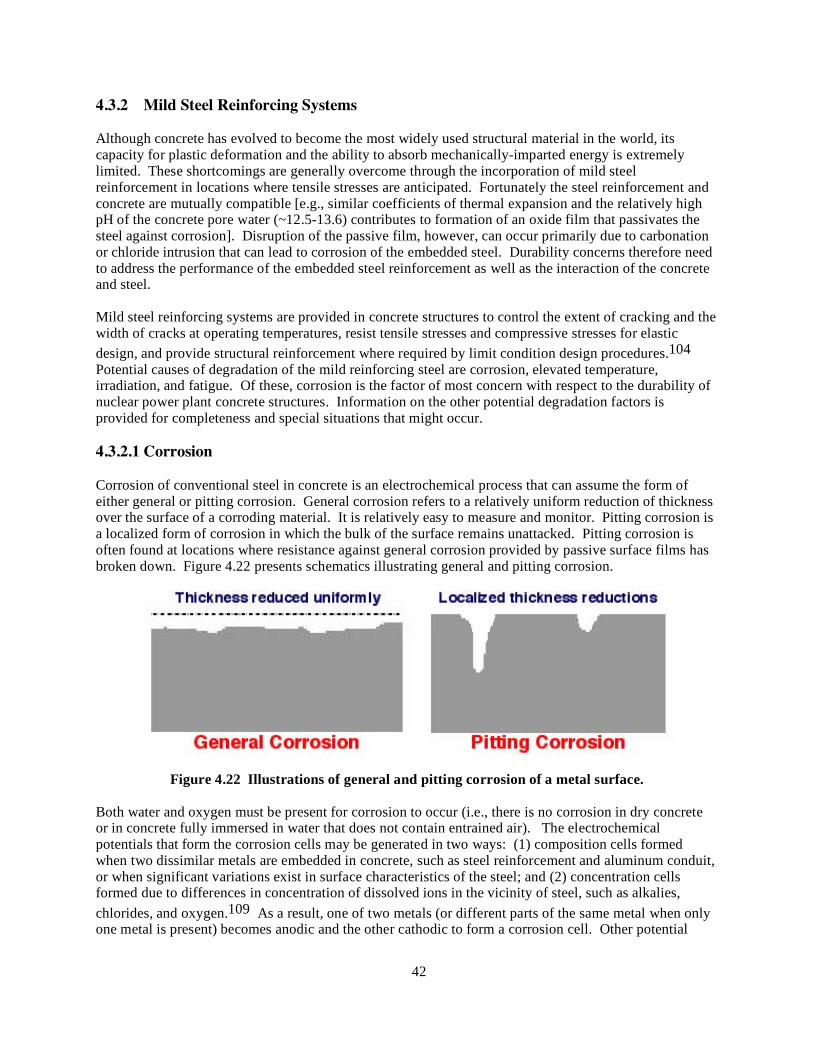
42
4.3.2 Mild Steel Reinforcing Systems Although concrete has evolved to become the most widely used structural material in the world, its capacity for plastic deformation and the ability to absorb mechanically-imparted energy is extremely limited. These shortcomings are generally overcome through the incorporation of mild steel reinforcement in locations where tensile stresses are anticipated. Fortunately the steel reinforcement and concrete are mutually compatible [e.g., similar coefficients of thermal expansion and the relatively high pH of the concrete pore water (~12.5-13.6) contributes to formation of an oxide film that passivates the steel against corrosion]. Disruption of the passive film, however, can occur primarily due to carbonation or chloride intrusion that can lead to corrosion of the embedded steel. Durability concerns therefore need to address the performance of the embedded steel reinforcement as well as the interaction of the concrete and steel. Mild steel reinforcing systems are provided in concrete structures to control the extent of cracking and the width of cracks at operating temperatures, resist tensile stresses and compressive stresses for elastic design, and provide structural reinforcement where required by limit condition design procedures.104 Potential causes of degradation of the mild reinforcing steel are corrosion, elevated temperature, irradiation, and fatigue. Of these, corrosion is the factor of most concern with respect to the durability of nuclear power plant concrete structures. Information on the other potential degradation factors is provided for completeness and special situations that might occur. 4.3.2.1 Corrosion Corrosion of conventional steel in concrete is an electrochemical process that can assume the form of either general or pitting corrosion. General corrosion refers to a relatively uniform reduction of thickness over the surface of a corroding material. It is relatively easy to measure and monitor. Pitting corrosion is a localized form of corrosion in which the bulk of the surface remains unattacked. Pitting corrosion is often found at locations where resistance against general corrosion provided by passive surface films has broken down. Figure 4.22 presents schematics illustrating general and pitting corrosion.
Figure 4.22 Illustrations of general and pitting corrosion of a metal surface. Both water and oxygen must be present for corrosion to occur (i.e., there is no corrosion in dry concrete or in concrete fully immersed in water that does not contain entrained air). The electrochemical potentials that form the corrosion cells may be generated in two ways: (1) composition cells formed when two dissimilar metals are embedded in concrete, such as steel reinforcement and aluminum conduit, or when significant variations exist in surface characteristics of the steel; and (2) concentration cells formed due to differences in concentration of dissolved ions in the vicinity of steel, such as alkalies, chlorides, and oxygen.109 As a result, one of two metals (or different parts of the same metal when only one metal is present) becomes anodic and the other cathodic to form a corrosion cell. Other potential

43
causes of corrosion include the effects of stray electrical currents or galvanic action with an embedded steel of different metallurgy. Figure 4.23 illustrates the electrochemical process of steel corrosion in moist and permeable concrete. Four fundamental components are necessary for an electrochemical corrosion cell: (1) anode, (2) cathode, (3) electrolyte, and (4) electrical connection between anode and cathode. Figure 4.24 presents examples of steel reinforcement corrosion in general civil engineering structures.
Figure 4.23 Electrochemical reaction illustrating corrosion of steel in concrete. Source: P. J. M. Monteiro, “Structure and Properties of Engineering Materials,“ CE60, Department of Civil and Structural Engineering, University of California, Berkeley, Fall 2005.
Figure 4.24 Corrosion of reinforced concrete: (a) sea water structure, (b) bridge structure. Source: (a) T. U. Mohammed, “Durability Related Issues of Concrete Structures Under Marine Exposure,” Invited Lecture Port and Airport Research Institute, Keikyu Kurihama, Japan, January 29, 2004 (www.hucc.hokudai.ac.jp/~m16120/coe/microstructure.htm), (b) Corrosion Club (www.corrosion-club.com/rebarimages.htm). In good-quality, well-compacted concrete, reinforcing steel with adequate cover should not be susceptible to corrosion because the highly alkaline conditions present within the concrete (pH > 12) causes a passive iron oxide film (gamma Fe2O3) to form on the surface (i.e., metallic iron will not be available for anodic

44
activity). The passive film may be relatively thick to inhibit corrosion by providing a diffusion barrier to the reaction products of the reacting species (Fe and O2), or as is more common, the layer can be very thin. The passive film does not actually stop corrosion, but reduces the corrosion rate to an insignificant level.152 Corrosion can occur if this passivating environment is altered by a reduction of the pH of the concrete or by introduction of chlorides that destabilize the passive layer. Figure 4.25 summarizes primary and secondary factors that can depassivate the steel reinforcement.153 The discussion below will only address the primary factors.
Figure 4.25 Factors leading to depassivation of steel in concrete. Source: J. A. González, S. Feliu, S. Rodríguez, P. W. Ramírez, and C. Andrade, “Some Questions on the Corrosion of Steel in Concrete – Part 1: When, How and How Much Steel Corrodes,” Materials and Structures 29, pp. 40-46, January-February 1996. Reduction of the concrete pH can occur as a result of leaching of alkaline substances by water or carbonation [i.e., calcium hydroxide is converted to calcium carbonate (calcite)].∗ It has been reported that when the concrete pH falls below about 11.5, a porous oxide layer (rust) can form on the reinforcing steel due to corrosion.155 More recent research indicates that the corrosion threshold is considered to be reached once the pH is reduced to 9.5 and there is a steep decrease in the electrochemical corrosion potential indicating decomposition of the passive layer at a pH about 8.156 Carbon dioxide is a minor component of the atmosphere (~0.03% by volume). The penetration of carbon dioxide from the environment is generally a slow process dependent on the concrete permeability, the concrete moisture content, and the carbon dioxide content, temperature, and relative humidity of the ambient medium (i.e., ∗ Carbonation causes the strength of concrete to increase, but this is generally of insignificant consequence because normally only the surface zone becomes carbonated. Although carbonation reduces the concrete permeability, it produces a greater propensity for shrinkage cracking that can negate the positive durability effects of reduced permeability.154

45
50 to 75% R.H. with 60-65% being maximum and extremes being capable of preventing carbonation). The rate of carbonation at exposed surfaces is considered to be roughly proportional to the square root of time for concrete kept continuously dry at normal relative humidities.157 Carbonation generally proceeds in concrete as a front, beyond which the concrete is unaffected, and behind which the pH is reduced. As shown in Figure 4.26, carbonation penetrates more quickly near the corners where reinforcement usually comes closest to the surface, and into concrete where it is cracked and along reinforcement where it is locally unbonded.158 Table 4.9 provides some guidance on expected depths of carbonation for various grades (strengths) of concrete according to time and exposure type.159 Results in the table indicate that the depth of carbonation increases as the concrete strength (permeability) decreases. Also the depth of carbonation is greater for concrete stored indoors than outdoors where moisture helps prevent the ingress of carbon dioxide. Table 4.10 indicates expected times to corrosion (in years) for various water/cement ratios and depths of cover.160 The expected time to corrosion increases as the concrete cover increases and the water/cement ratio decreases.
Figure 4.26 Carbonation penetration. Source: P. Pullar-Strecker, Corrosion Damaged Concrete Assessment and Repair, Butterworths, London, United Kingdom, 1987.
Table 4.9 Expected carbonation depths for different strength concretes and storage conditions
Concrete strength
Storage conditions Carbonation depth (mm) at time t
t = 1 year
t = 2 years
t = 5 years
t = 10 years
t = 25 years
Low Outdoors (moist) 6 9 13 19 30 Indoors 10 14 22 32 50
Medium Outdoors(moist) 2 3 4 6 10 Indoors 5 7 11 16 25
High Outdoors(moist) 1 1.5 2 3 5 Indoors 2 3 4 6 10
Source: R. T. L. Allen, and A. Forrester, “The Investigation and Repair of Damaged Reinforced Concrete Structures,” Corrosion of Reinforcement in Concrete Construction, Society of Chemical Industry, Ellis Horwood, Chichester, United Kingdom, 1983.
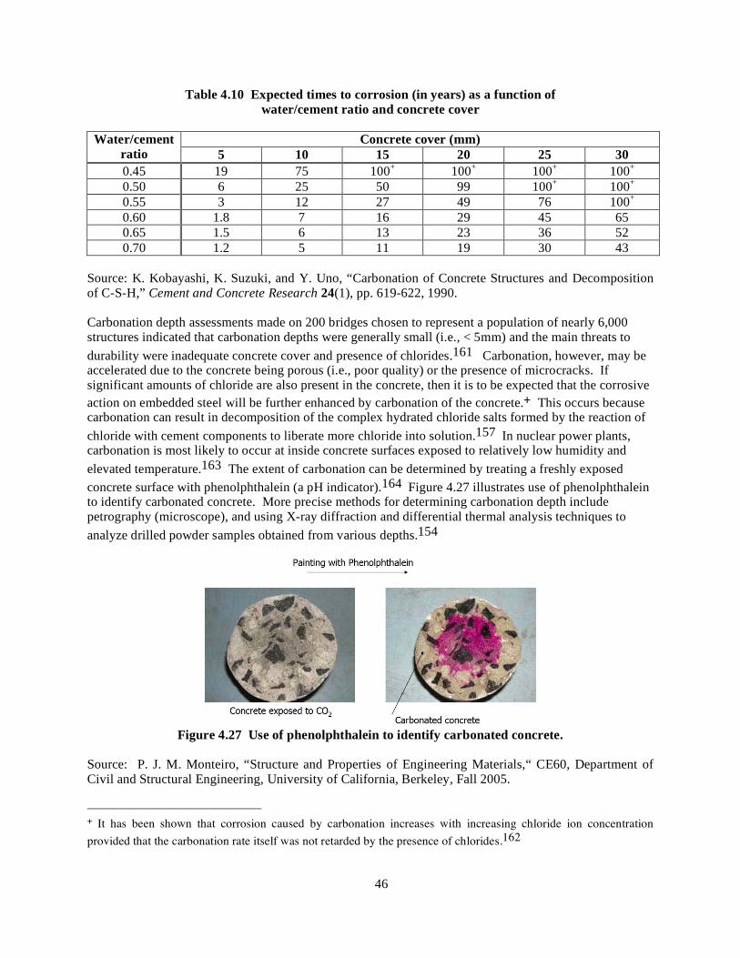
46
Table 4.10 Expected times to corrosion (in years) as a function of water/cement ratio and concrete cover
Concrete cover (mm) Water/cement
ratio 5 10 15 20 25 30 0.45 19 75 100+ 100+ 100+ 100+ 0.50 6 25 50 99 100+ 100+ 0.55 3 12 27 49 76 100+ 0.60 1.8 7 16 29 45 65 0.65 1.5 6 13 23 36 52 0.70 1.2 5 11 19 30 43
Source: K. Kobayashi, K. Suzuki, and Y. Uno, “Carbonation of Concrete Structures and Decomposition of C-S-H,” Cement and Concrete Research 24(1), pp. 619-622, 1990. Carbonation depth assessments made on 200 bridges chosen to represent a population of nearly 6,000 structures indicated that carbonation depths were generally small (i.e., < 5mm) and the main threats to durability were inadequate concrete cover and presence of chlorides.161 Carbonation, however, may be accelerated due to the concrete being porous (i.e., poor quality) or the presence of microcracks. If significant amounts of chloride are also present in the concrete, then it is to be expected that the corrosive action on embedded steel will be further enhanced by carbonation of the concrete.+ This occurs because carbonation can result in decomposition of the complex hydrated chloride salts formed by the reaction of chloride with cement components to liberate more chloride into solution.157 In nuclear power plants, carbonation is most likely to occur at inside concrete surfaces exposed to relatively low humidity and elevated temperature.163 The extent of carbonation can be determined by treating a freshly exposed concrete surface with phenolphthalein (a pH indicator).164 Figure 4.27 illustrates use of phenolphthalein to identify carbonated concrete. More precise methods for determining carbonation depth include petrography (microscope), and using X-ray diffraction and differential thermal analysis techniques to analyze drilled powder samples obtained from various depths.154
Figure 4.27 Use of phenolphthalein to identify carbonated concrete.
Source: P. J. M. Monteiro, “Structure and Properties of Engineering Materials,“ CE60, Department of Civil and Structural Engineering, University of California, Berkeley, Fall 2005.
+ It has been shown that corrosion caused by carbonation increases with increasing chloride ion concentration provided that the carbonation rate itself was not retarded by the presence of chlorides.162

47
The most common cause of initiation of corrosion of steel in concrete is the presence of chloride ions that can destroy the passive iron oxide film on the steel reinforcement even at high alkalinity (pH > 11.5) [e.g., it has been noted that at a pH of 13.2 more than 8000 ppm of chloride ions are required to induce corrosion, however, at a pH of 11.6 only about 71 ppm are required].163 The mechanism through which the gamma Fe2O3 film is destroyed is not fully understood in that either the chloride ions convert the insoluble iron oxide to soluble iron chloride or they become included in the oxide layer in a manner that makes it permeable to air.110 Chloride penetration also introduces a source of variation in concentration along the steel, forming concentration cells. Chloride ions are attracted to anodic regions of the steel to increase the local concentration. Increased acidity in the region of the anodic sites also can lead to local dissolution of the cement paste.
Cracks resulting from such causes as direct loading of the structure, or due to chemical or physical causes, can allow the rapid penetration of carbon dioxide or chloride ions to the steel reinforcement, thereby causing local failure of the passive oxide film.∗ This may lead to concentration of corrosion over a small area resulting in pitting corrosion and can be of concern as it may lead to reduction in bar cross-section. The volume of corrosion products may be so small that no external signs appear. It has been indicated that the presence of the crack is more important than its width, particularly when in the tension zone of a loaded beam (i.e., the crack width influences the speed at which corrosion begins but because this period is short, the influence is limited and the width has only an infinitesimal effect on the spread of corrosion).166 Diffusion of chlorides can occur in sound concrete and proceed through the capillary pore structure of the cement paste. Thus cracks in the concrete are not a prerequisite for transporting chlorides to the reinforcing steel. The rate of diffusion is strongly dependent on a number of factors (e.g., water/cementitious material ratio, type cement, temperature, and maturity of concrete). Some of the chlorides react chemically with cement components (e.g., calcium aluminates) and are effectively removed from the pore solution. The fraction of total chlorides available in the pore solution to cause a breakdown of the passive film is a function of a number of parameters [e.g., C3A and C4AF content, pH, and source of chlorides (mix or environment)]. The threshold value of chloride concentration below which significant corrosion does not occur is also dependent on these parameters. Different organizations have proposed various values: British Standard 8110 and European Standard ENV list 0.4% Cl by mass cement,4,167 whereas the American Concrete Institute Building Code lists 0.15% water soluble Cl by mass cement.5 Investigators have reported minimum threshold values for chloride ion contents to initiate corrosion in the range of 0.026 to 0.033% (approximately 0.6 to 0.8 kg/m3) total chloride ion content by mass of concrete.152 The threshold acid-soluble-chloride contents to initiate steel corrosion reported by various investigators range from 0.15 to 1.0%.168 However, as shown in Figure 4.28, the critical chloride content can be higher or lower than the proposed values depending on whether the concrete is carbonated or not and the environment (i.e., relative humidity).57
∗ In tests where cracked reinforced concrete beams were exposed to a marine environment, it was found that corrosion was somewhat accelerated in the regions of flexural cracks, however, longitudinal cracking produced by corrosion dominates corrosion occurrence with the initiation and growth of the longitudinal cracks controlled by the restraining action of transverse reinforcement.165 Once the longitudinal cracking exceeded a critical length, the corrosion rate accelerates. Appendix C provides additional information on the relation between cracking and corrosion.

48
Figure 4.28 Variation of critical chloride content with environment.
Source: Durable Concrete Structures — Design Guide, Comite Euro-International de Beton, Thomas Telford Service Publisher, London, United Kingdom, 1992. Chlorides may be present in concrete due to external sources (sea water effects, deicing salts, etc.) or may be naturally introduced into the concrete via aggregate or mix water transport.+ Furthermore, when large amounts of chloride are present, concrete tends to hold more moisture, which also increases the risk of steel corrosion by lowering concrete's electrical resistivity. Once the passivity of the steel is destroyed, the electrical resistivity of concrete and availability of oxygen control the rate of corrosion. Oxygen availability at cathodic sites is essential for corrosion to occur. In some instances where the oxygen supply is limited at active anodes the resulting corrosion products may be green, white or black in color.170 The green product probably is a chloride complex while the black product is magnetite (Fe3O4). Corrosion under oxygen-deficient conditions such as this is considered to be more serious than haematite (Fe2O3•3 H2O), or normal red-brown rust, since it may go on some time before any visible evidence.
The transformation of metallic iron to ferric oxide (rust) is accompanied by an increase in volume. Figure 4.29a indicates that, depending on the oxidation state, metallic iron can increase more than six times in volume. Volume increase associated with the transformation can cause cracking, spalling, and delamination of the concrete that can be visible in the form of rust spots, cracks in the concrete cover along the line of bars, spalling, and delamiantion as noted in Figure 4.29b. Generally, because the corrosion is fairly uniform, cracking of the cover concrete in normally reinforced structures usually occurs prior to a particular structural cross-section becoming excessively weak, thus giving visual warning of the deterioration.171 Occasionally, however, cover spalling occurs before any visible sign of
+ A distinction needs to be made between chlorides added during the mix and those acquired by diffusing into the concrete from the environment. Added chlorides can combine with C3A and ferric compounds in cement to give Friedel’s salt, whereas chlorides resulting from diffusion can not. Chlorides from diffusion therefore are potentially more hazardous.169

49
Figure 4.29 Oxidation states of iron and representations of visible forms of corrosion. Sources: (a) P. K. Mehta, Concrete-Structure, Properties, and Materials, Prentice-Hall, Inc., Englewood Cliffs, New Jersey, 1986; (b) Diagnosis of Deterioration in Concrete Structures – Identification of Defects, Evaluation and Development of Remedial Action, Technical Report No. 54, The Concrete Society, Century House, Berkshire, United Kingdom, 2000. deterioration at the concrete surface is apparent. Figure 4.30 summarizes the effects of corrosion on reinforced concrete structures.153
Figure 4.30 Effects of corrosion on reinforced concrete structures. Source: J. A. González, S. Feliu, S. Rodríguez, P. W. Ramírez, and C. Andrade, “Some Questions on the Corrosion of Steel in Concrete – Part 1: When, How and How Much Steel Corrodes,” Materials and Structures 29, pp. 40-46, January-February 1996. Structural strength and serviceability are only reduced and jeopardized when corrosion of reinforcement causes a significant loss of steel cross section and/or there occurs a loss of bond between the steel and concrete.172 This is supported by results of tests of corrosion-affected beams detailed with adequate development length and shear stirrups.173 In these tests there was no significant loss of bond up to about 5% corrosion, as measured by loss of metal mass. After 5% corrosion, only a 12% reduction was
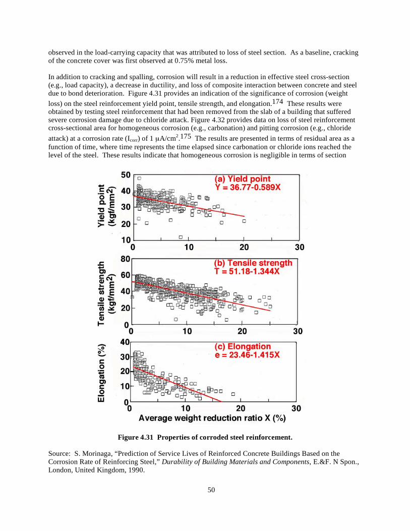
50
observed in the load-carrying capacity that was attributed to loss of steel section. As a baseline, cracking of the concrete cover was first observed at 0.75% metal loss. In addition to cracking and spalling, corrosion will result in a reduction in effective steel cross-section (e.g., load capacity), a decrease in ductility, and loss of composite interaction between concrete and steel due to bond deterioration. Figure 4.31 provides an indication of the significance of corrosion (weight loss) on the steel reinforcement yield point, tensile strength, and elongation.174 These results were obtained by testing steel reinforcement that had been removed from the slab of a building that suffered severe corrosion damage due to chloride attack. Figure 4.32 provides data on loss of steel reinforcement cross-sectional area for homogeneous corrosion (e.g., carbonation) and pitting corrosion (e.g., chloride attack) at a corrosion rate (Icorr) of 1 µA/cm2.175 The results are presented in terms of residual area as a function of time, where time represents the time elapsed since carbonation or chloride ions reached the level of the steel. These results indicate that homogeneous corrosion is negligible in terms of section
Figure 4.31 Properties of corroded steel reinforcement.
Source: S. Morinaga, “Prediction of Service Lives of Reinforced Concrete Buildings Based on the Corrosion Rate of Reinforcing Steel,” Durability of Building Materials and Components, E.&F. N Spon., London, United Kingdom, 1990.

51
Figure 4.32 Residual cross-sectional area of steel reinforcement as a function of type and longevity of corrosion.
Source: J. Rodriguez, L. M. Ortega, J. Casal, and J. M. Diez, “Corrosion of Reinforcement and Service Life of Concrete Structures,” 7th International Conference on the Durability of Building Materials and Components, Stockholm, Sweden, 1996. reduction for high diameter bars, but pitting corrosion has a relevant effect in small diameter bars. Reductions in elongation at maximum load of 30 and 50% have been reported for cross-section losses of 15 and 28%, respectively.176 Although reduced, the elongation reductions generally still exceeded the minimum code requirements. Bond pull-out data for 150–mm concrete cubes containing bars having diameters of either 10, 14, or 20 mm indicate that up to 1 percent corrosion (loss of bar weight), the bond strength increases (up to about 50%) with increasing corrosion.173 This can be explained on the basis of increased surface roughness of the bars with the growth of firm rust that tends to enhance the holding capacity. However, with further corrosion the bond stress declines consistently until it becomes negligible for about 8.5, 7.5, and 6.5 percent corrosion for the 10, 14, and 20-mm bars, respectively. The significant degradation of bar lugs and reduction of section, as well as a heavy layer of corroded material adhering to the concrete at these corrosion levels contribute to the significant decline in bond stress (e.g., loss of mechanical interlocking between ribs and deterioration of concrete, and influence of lubricating effect of flaky corroded material between bars and concrete). The interrelationship of cover concrete, bar diameter, and corrosion was investigated.177 Cylindrical specimens either 100- or 150-mm diameter by 100-mm high containing either a 9-, 19-, or 25-mm diameter bar with an embedment length of 100 mm were subjected to different degrees of corrosion (i.e., rebar weight loss). Test results indicate that the concrete-rebar bond strength increased (up to 200 or 300%) with increasing corrosion until sufficient corrosion was induced to produce concrete cracking. With increasing surface cracking the bond strength decreased. It was found for constant bar diameter that the bond strength increased as the cover thickness increased. Also, for constant cover thickness it was found that the bond strength increased as the bar diameter decreased. Results of bond tests using cubic specimens reinforced with four bars at the corners indicated that if the cover is cracked by reinforcement corrosion, neither the concrete quality nor the concrete cover to rebar diameter ratio (C/d) influenced the residual bond strength.175 Bond test results have also been presented using 100-mm diameter by 1-m long concrete specimens containing a single longitudinal No. 20 bar (C/d = 2) that was corroded to levels representing weight loss of bar material ranging from 0 to 17.5%.178 Average surface concrete crack widths obtained for corrosion levels (weight loss) of 4, 5.5, 11, 11.5, 12, and 17.5% were 0.15, 0.2, 6.0, 1.5 to 3.0, 1.5 to 4.0, and 9.0 mm, respectively. Tensile force-elongation results for these specimens indicated that as the level of corrosion
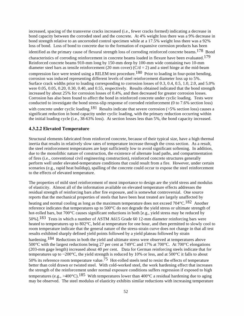
52
increased, spacing of the transverse cracks increased (i.e., fewer cracks formed) indicating a decrease in bond capacity between the corroded steel and the concrete. At 4% weight loss there was a 9% decrease in bond strength relative to an uncorroded control specimen while at a 17.5% weight loss there was a 92% loss of bond. Loss of bond to concrete due to the formation of expansive corrosion products has been identified as the primary cause of flexural strength loss of corroding reinforced concrete beams.178 Bond characteristics of corroding reinforcement in concrete beams loaded in flexure have been evaluated.179 Reinforced concrete beams 910-mm long by 150-mm deep by 100-mm wide containing two 10-mm diameter steel bars as tensile reinforcement (20 mm cover) (C/d = 2) and a steel hinge at the mid-beam compression face were tested using a RILEM test procedure.180 Prior to loading in four-point bending, corrosion was induced representing different levels of steel reinforcement diameter loss up to 5%. Surface crack widths prior to loading corresponding to corrosion losses of 0.3, 0.4, 0.5, 1.0, 2.0, and 5.0% were 0.05, 0.05, 0.20, 0.30, 0.40, and 0.55, respectively. Results obtained indicated that the bond strength increased by about 25% for corrosion losses of 0.4%, and then decreased for greater corrosion losses. Corrosion has also been found to affect the bond in reinforced concrete under cyclic loading. Tests were conducted to investigate the bond stress-slip response of corroded reinforcement (0 to 7.6% section loss) with concrete under cyclic loading.181 Results indicate that severe corrosion (>5% section loss) causes a significant reduction in bond capacity under cyclic loading, with the primary reduction occurring within the initial loading cycle (i.e., 38-63% loss). At section losses less than 5%, the bond capacity increased. 4.3.2.2 Elevated Temperature Structural elements fabricated from reinforced concrete, because of their typical size, have a high thermal inertia that results in relatively slow rates of temperature increase through the cross section. As a result, the steel reinforcement temperatures are kept sufficiently low to avoid significant softening. In addition, due to the monolithic nature of construction, the existence of alternate load paths, and compartmentation of fires (i.e., conventional civil engineering construction), reinforced concrete structures generally perform well under elevated-temperature conditions that could result from a fire. However, under certain scenarios (e.g., rapid heat buildup), spalling of the concrete could occur to expose the steel reinforcement to the effects of elevated temperature. The properties of mild steel reinforcement of most importance to design are the yield stress and modulus of elasticity. Almost all of the information available on elevated temperature effects addresses the residual strength of reinforcing bars after fire exposure, and is somewhat controversial. One source reports that the mechanical properties of steels that have been heat treated are largely unaffected by heating and normal cooling as long as the maximum temperature does not exceed 704°C.182 Another reference indicates that temperatures up to 500°C do not degrade the yield stress or ultimate strength of hot-rolled bars, but 700°C causes significant reductions in both [e.g., yield stress may be reduced by 50%].183 Tests in which a number of ASTM A615 Grade 60 12-mm diameter reinforcing bars were heated to temperatures up to 802°C, held at temperature for one hour, and then permitted to slowly cool to room temperature indicate that the general nature of the stress-strain curve does not change in that all test results exhibited sharply defined yield points followed by a yield plateau followed by strain hardening.184 Reductions in both the yield and ultimate stress were observed at temperatures above 500°C with the largest reductions being 27 per cent at 749°C and 17% at 700°C. At 700°C elongations (203-mm gage length) increased about 40 per cent. Data for German reinforcing steels indicate that for temperatures up to ~200°C, the yield strength is reduced by 10% or less, and at 500°C it falls to about 50% its reference room temperature value.75 Hot-rolled steels tend to resist the effects of temperature better than cold drawn or twisted steel. With cold-worked steel, the work hardening effect that increases the strength of the reinforcement under normal exposure conditions suffers regression if exposed to high temperatures (e.g., >400°C).185 With temperatures lower than 400°C a residual hardening due to aging may be observed. The steel modulus of elasticity exhibits similar reductions with increasing temperature
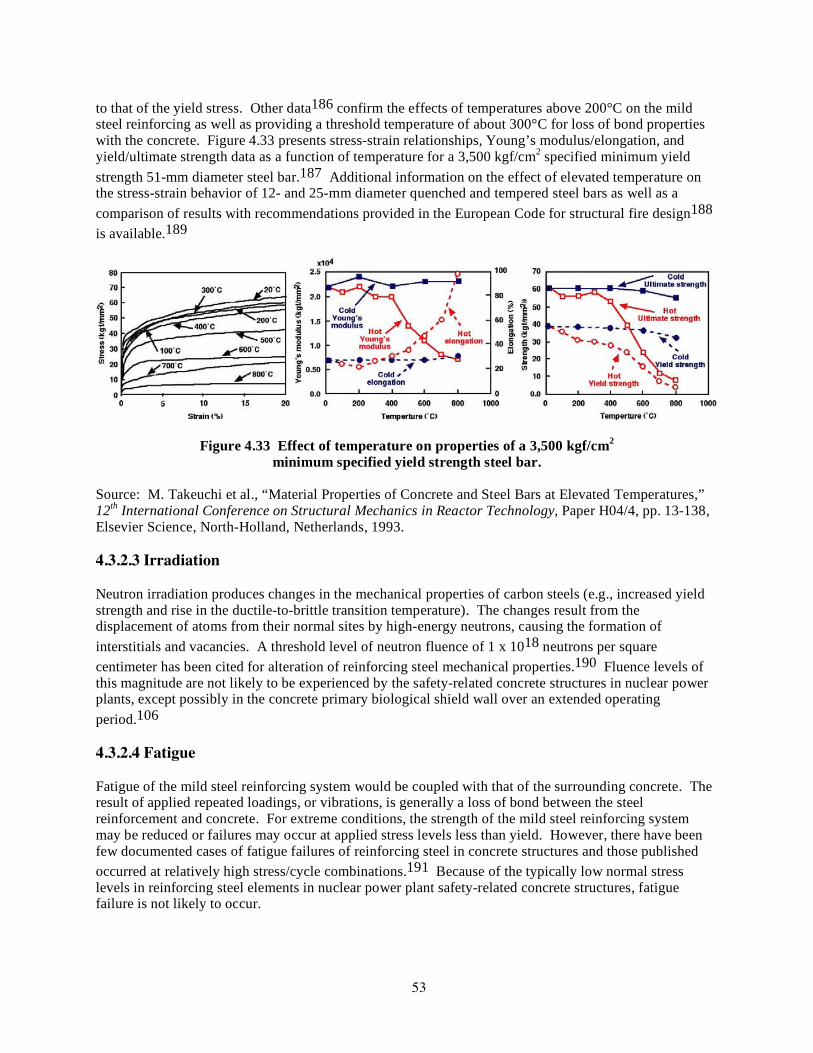
53
to that of the yield stress. Other data186 confirm the effects of temperatures above 200°C on the mild steel reinforcing as well as providing a threshold temperature of about 300°C for loss of bond properties with the concrete. Figure 4.33 presents stress-strain relationships, Young’s modulus/elongation, and yield/ultimate strength data as a function of temperature for a 3,500 kgf/cm2 specified minimum yield strength 51-mm diameter steel bar.187 Additional information on the effect of elevated temperature on the stress-strain behavior of 12- and 25-mm diameter quenched and tempered steel bars as well as a comparison of results with recommendations provided in the European Code for structural fire design188 is available.189
Figure 4.33 Effect of temperature on properties of a 3,500 kgf/cm2 minimum specified yield strength steel bar.
Source: M. Takeuchi et al., “Material Properties of Concrete and Steel Bars at Elevated Temperatures,” 12th International Conference on Structural Mechanics in Reactor Technology, Paper H04/4, pp. 13-138, Elsevier Science, North-Holland, Netherlands, 1993. 4.3.2.3 Irradiation Neutron irradiation produces changes in the mechanical properties of carbon steels (e.g., increased yield strength and rise in the ductile-to-brittle transition temperature). The changes result from the displacement of atoms from their normal sites by high-energy neutrons, causing the formation of interstitials and vacancies. A threshold level of neutron fluence of 1 x 10¹⁸ neutrons per square centimeter has been cited for alteration of reinforcing steel mechanical properties.190 Fluence levels of this magnitude are not likely to be experienced by the safety-related concrete structures in nuclear power plants, except possibly in the concrete primary biological shield wall over an extended operating period.106 4.3.2.4 Fatigue Fatigue of the mild steel reinforcing system would be coupled with that of the surrounding concrete. The result of applied repeated loadings, or vibrations, is generally a loss of bond between the steel reinforcement and concrete. For extreme conditions, the strength of the mild steel reinforcing system may be reduced or failures may occur at applied stress levels less than yield. However, there have been few documented cases of fatigue failures of reinforcing steel in concrete structures and those published occurred at relatively high stress/cycle combinations.191 Because of the typically low normal stress levels in reinforcing steel elements in nuclear power plant safety-related concrete structures, fatigue failure is not likely to occur.
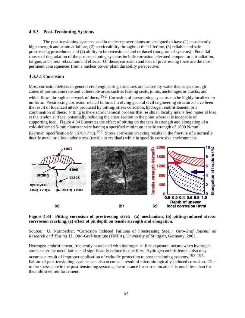
54
4.3.3 Post-Tensioning Systems The post-tensioning systems used in nuclear power plants are designed to have (1) consistently high strength and strain at failure, (2) serviceability throughout their lifetime, (3) reliable and safe prestressing procedures, and (4) ability to be retensioned and replaced (nongrouted systems). Potential causes of degradation of the post-tensioning systems include corrosion, elevated temperature, irradiation, fatigue, and stress relaxation/end effects. Of these, corrosion and loss of prestressing force are the most pertinent consequences from a nuclear power plant durability perspective. 4.3.3.1 Corrosion Most corrosion defects in general civil engineering structures are caused by water that seeps through zones of porous concrete and vulnerable areas such as leaking seals, joints, anchorages or cracks, and which flows through a network of ducts.192 Corrosion of prestressing systems can be highly localized or uniform. Prestressing corrosion-related failures involving general civil engineering structures have been the result of localized attack produced by pitting, stress corrosion, hydrogen embrittlement, or a combination of these. Pitting is the electrochemical process that results in locally intensified material loss at the tendon surface, potentially reducing the cross section to the point where it is incapable of supporting load. Figure 4.34 illustrates the effect of pitting on the tensile strength and elongation of a cold-deformed 5-mm diameter wire having a specified minimum tensile strength of 1800 N/mm2 (German Specification St 1570/1770).192 Stress corrosion cracking results in the fracture of a normally ductile metal or alloy under stress (tensile or residual) while in specific corrosive environments.
Figure 4.34 Pitting corrosion of prestressing steel: (a) mechanism, (b) pitting-induced stress-corrrosion cracking, (c) effect of pit depth on tensile strength and elongation. Source: U. Nürnberber, “Corrosion Induced Failures of Prestressing Steel,” Otto-Graf Journal on Research and Testing 13, Otto-Graf-Institute (FMPA), University of Stuttgart, Germany, 2002. Hydrogen embrittlement, frequently associated with hydrogen sulfide exposure, occurs when hydrogen atoms enter the metal lattice and significantly reduce its ductility. Hydrogen embrittlement also may occur as a result of improper application of cathodic protection to post-tensioning systems.193-195 Failure of post-tensioning systems can also occur as a result of microbiologically-induced corrosion. Due to the stress state in the post-tensioning systems, the tolerance for corrosion attack is much less than for the mild steel reinforcement.

55
4.3.3.2 Elevated Temperature The effect of elevated temperature on all heat-treated and drawn wires can be significant, and on cooling the wires may not regain their initial strength because the heating destroys the crystal transformations achieved by the heat-treating process. Short-term heating, on the order of 3 to 5 min., even to temperatures as high as 400°C, however, may not harm the prestressing wire's mechanical properties.196 Results of a Belgian study75 involving 30 types of prestressing steel indicate that thermal exposures up to ~200°C do not significantly reduce (< 10%) the tensile strength of prestressing wires or strands. Other research supports results of the Belgian study.197,198 Elevated-temperature exposures also affect the relaxation and creep properties of prestressing tendons. Studies in the United Kingdom indicate that losses in a 15.2-mm-diameter strand initially stressed to 75% of its guaranteed ultimate tensile strength at 40°C will be 5 to 6.4% after 30 years.199 Relaxation losses of tendons composed of stress-relieved wires are of about the same magnitude as stress-relieved strand, but relaxation of a strand is greater than that of its straight constituent wire because of the combined stress relaxation in the helical wires.200 Creep (length change under constant stress) of stress-relieved wire is negligible up to 50% its tensile strength. Also, the creep effect in steel varies with its chemical composition as well as with mechanical and thermal treatment applied during the manufacturing process. As temperature levels experienced by the prestressing tendons in light-water reactor facilities are below 200°C, the possibility for thermal damage to the prestressing steels under normal operating conditions is low. Elevated temperature may increase the creep of concrete in the vicinity of tendon anchorage zones which can lead to loss of prestressing force. 4.3.3.3 Irradiation Irradiation of post-tensioning system steel affects its mechanical properties because atoms are displaced from their normal sites by high-energy neutrons to form interstitials and vacancies. These defects can propagate or combine and effectively both strengthen the steel and reduce its ductility; or, at higher temperatures, they can recombine and annihilate each other and, for a given neutron dose, reduce the irradiation damage.190 Results obtained from studies190 in which 2.5-mm-diam prestressing wires were stressed to 70% of their tensile strength and irradiated to a total dose of 4 x 10¹⁶ neutrons per square centimeter (flux of 2 x 10¹⁰ neutrons·cm2·per s) showed that for exposures up to this level, the relaxation behavior of irradiated and unirradiated materials was similar. These flux levels are higher than the level likely to be experienced in a light-water reactor containment vessel.
4.3.3.4 Fatigue Repeated reversals of stress, or variations in stress, applied to concrete structural elements (beams in particular) can result in fatigue failure in any of the following modes: (1) failure of the concrete due to flexural compression; (2) failure of the concrete due to diagonal tension or shear; (3) failure of the prestressing steel due to flexural, tensile-stress variations; (4) failure of pre-tensioned beams (grouted tendons) due to loss of bond stress; and (5) failure of the end anchorages of post-tensioned structures.201 The majority of fatigue failures that occurred while testing prestressed concrete beams have resulted from fatigue of the tendons due to stress concentrations that occur in the tendon at a location where a crack occurs. In unbonded post-tensioned construction, the end anchorages could be subjected to some variation in stress under the action of changing external load, but unbonded tendons are not generally used in members subjected to frequent variations in stress. High-cycle and low-cycle dynamic tensile test requirements for prestressing tendon systems used in concrete containments are available.104
56
4.3.3.5 Loss of Prestressing Force Maintaining an adequate level of prestressing force in post-tensioned concrete containments is important to the overall safety of the nuclear power plant, especially during postulated accident conditions. Primary contributors to the loss of initial force level that was applied by the prestressing tendons include (1) friction, (2) end anchorage deflection (take up end slip), (3) elastic shortening, (4) tendon relaxation, and (5) concrete creep and shrinkage.196,202-204 Of these factors, tendon relaxation and concrete creep and shrinkage are time-dependent factors and thus aging related. Stress relaxation, defined as loss of stress (force) in the steel when the strain (elongation) does not vary, is related to tendon material properties, initial stress level, exposure temperature, and time. Creep and shrinkage of concrete represent volume changes of the concrete that occur over the life of the structure that can significantly affect the force levels in the tendons. Guidelines for developing surveillance programs acceptable to the U.S. Nuclear Regulatory Commission and for providing reasonable assurance (when properly implemented) that the structural integrity of the containment is being maintained were provided in a Regulatory Guide.205 A companion to the Regulatory Guide provides clarification with respect to determination of prestressing forces and prediction of prestressing force losses over the service life of the structure.206 Additional information on inspection of post-tensioning systems is available in Subsection IWL of Section XI of the ASME Boiler and Pressure Vessel Code.9 4.3.4 Liner and Structural Steel Liner and structural steel members are subject to the same general degradation mechanisms as the steel reinforcement. Of these, corrosion and fatigue are of most importance with respect to aging. Except for structural steel members that assist in providing support for the reactor pressure vessels in certain plants (e.g., Trojan and Turkey Point), these members are generally not subjected to the effects of elevated temperature or irradiation. 4.3.4.1 Corrosion The primary degradation factor for the liner plate and structural steel (both embedded sections and those within containment) is corrosion. Typically the liner plate and any installed steel are coated, either with a primer or a primer-finish coat system to prevent corrosion (e.g., zinc-rich primer with polyamide epoxy or modified phenolic coatings). Depending on the component, a corrosion allowance may also have been provided during the design stage. However, little allowance will have been provided for the relatively thin (i.e., ~6.3–mm) liner plate. The corrosion process that affects these components is similar to that for conventional reinforcing steel. Figure 4.35 presents a schematic representation of forms of corrosion that may be found on metals.207 For liner plates, the influence of local attack that can lead to loss of leak tightness is of most concern. Local attack may result due to accumulation of moisture in areas experiencing loss of coating integrity, or failure of adjoining floor-liner sealant. The rate of attack may be rapid, depending on the aggressiveness of the environment. Corrosion data for structural steel in numerous environments are available.208 For an industrial environment, the atmospheric (general) corrosion rate was found to be 0.02 to 0.04 mm/yr. This same reference reported pitting rates of 0.056 mm/yr for low carbon steels placed in polluted sea water. In general, depending on the environmental parameters, surface corrosion rates were noted to range from 0.001 mm/yr to 0.03 mm/yr.

57
Figure 4.35 Schematic representations of forms of corrosion that may be found in metals. Source: W. Swiat et al., State-of-the-Art Report — Corrosion of Steel in Concrete, ORNL/NRC/LTR-93/2, Martin Marietta Energy Systems, Inc., Oak Ridge National Laboratory, Oak Ridge, Tennessee, May 1993. Corrosion of structural steel piles, used in certain containment configurations for transferring foundation loadings to greater depths below grade, is also a possible degradation mechanism. Similar to other containment steel, the concern for piles is from localized corrosion resulting in significant loss of cross- sectional area. One study209 examined corrosion data from 43 piling installations of varying depths (up to 41.5 m) with times of exposure ranging from 7 to 50 years in a wide variety of conditions. The conclusion of this study was that the type and amount of corrosion observed in steel pilings driven in undisturbed soil, regardless of soil characteristics and properties, was not sufficient to significantly affect the piling's performance as load-bearing structures. However, pilings placed in oxygen-enhanced fills, those exposed above grade, or those exposed to sea water or salt spray may be somewhat affected.210
4.3.4.2 Fatigue The effects of repeated loads such as from polar crane operations or flow-induced vibrations may possibly detract from the function and performance of liner plate and structural steel members. The influence of repeated loads generally has been addressed at the design stage per national design codes. However, the effects of conditions outside of design predictions and local stress intensification points (material flaws, etc.) may result in fatigue-related problems. With respect to the liner plate, possible fatigue sites include base metal delaminations, weld defects, arc strikes, shape changes near penetrations, structural attachments, and concrete floor interfaces. For structural steel members (liner attachments and anchorages), the locations most susceptible to fatigue include large containment penetration framing (hatches, etc.) and liner anchorages near vibrating load conditions (such as those generated in structural attachments).

58

59
5 SUMMARY AND COMMENTARY Reinforced concrete structures almost from the time of construction will start to deteriorate in one form or another due to exposure to the environment (e.g., temperature, moisture, cyclic loadings, etc.).211 The rate of deterioration is dependent on the component's structural design, materials selection, quality of construction, curing, and aggressiveness of its environmental exposure. Termination of a component's service life occurs when it no longer can meet its functional and performance requirements. As noted by the deterioration of many roadways and bridges in the U.S.,212 this often occurs prior to achieving the desired service life. As concrete ages, changes in its properties will occur as a result of continuing microstructural changes (i.e., slow hydration, crystallization of amorphous constituents, and reactions between cement paste and aggregates), as well as environmental influences. These changes do not have to be detrimental to the point that concrete will not be able to meet its performance requirements. Concrete, however, can suffer undesirable changes with time because of improper specifications, a violation of specifications, or adverse performance of its cement paste matrix or aggregate constituents under either physical or chemical attack. Guidelines for production of durable concrete are available in national consensus codes and standards such as ACI 3185 that have been developed over the years through knowledge acquired in testing laboratories and supplemented by field experience. Serviceability of concrete has been incorporated into the codes through strength requirements and limitations on service load conditions in the structure (e.g., allowable crack widths, limitations on mid-span deflections of beams, and maximum service level stresses in prestressed members). Durability generally has been included through specifications for maximum water-cement ratios, requirements for entrained air, minimum concrete cover over reinforcement, etc. As life-cycle costs become increasingly important, development of high-performance concretes (e.g., incorporating supplementary cementitious materials to reduce permeability and inhibitors to reduce the corrosion of embedded metal) is receiving increased attention and will have application to construction of new nuclear power plants. Water is the single most important factor controlling the degradation processes of concrete (i.e., the process of deterioration of concrete with time is generally dependent on the transport of a fluid through concrete), apart from mechanical deterioration. The relationship between the concepts of concrete durability and performance was illustrated in Figure 1.1. The rate, extent, and effect of fluid transport are largely dependent on the concrete pore structure (i.e., size and distribution), presence of cracks, and microclimate at the concrete surface. The primary mode of transport in uncracked concrete is through the cement paste pore structure (i.e., its permeability). Although the coefficient of permeability for concrete depends primarily on the water-cement ratio and maximum aggregate size, permeability is influenced by the curing temperature, drying, and addition of chemical or mineral admixtures, as well as the tortuosity of the path of flow. Concrete strength, although a reasonable indicator of potential durability under most scenarios, may not be sufficient. It is also important that adequate cementitious materials be included in the concrete mix to reduce its permeability. Primary mechanisms (factors) that, under unfavorable conditions, can produce premature concrete deterioration include (1) freezing and thawing, (2) aggressive chemical exposure, (3) abrasion, (4) corrosion of steel reinforcement and other embedded metals, (5) chemical reactions of aggregates, and (6) other factors (e.g., unsound cement and shrinkage cracking). Table 5.1 lists primary degradation factors that can impact the performance of safety-relate concrete structures.18 As shown in this table, the most prevalent manifestation of concrete degradation is cracking. A description of the factors that can impact the performance of nuclear power plant safety-related concrete structures was provided in Chapter 4.

60
Table 5.1a Degradation factors that can impact the performance of reinforced concrete safety-related structures: concrete
Concrete
Aging Stressors/Service
Conditions Aging Mechanism Aging Effect Potential
Degradation Sites Remarks (e.g., Significance)
Percolation of fluid through
concrete due to moisture gradient
Leaching and efflorescence
Increased porosity and permeability; lowers strength
Near cracks; areas of high moisture
percolation
Makes concrete more vulnerable to
hostile environments; may
indicate other changes to cement paste; unlikely to
be an issue for high quality, low
permeability concretes
Exposure to alkali and magnesium
sulfates present in soils, sea water, or
ground water
Sulfate attack Expansion and irregular cracking
Subgrade structures and foundations
Sulfate-resisting cements or partial
replacement of cements used to
minimize occurrence
Exposure to aggressive acids
and bases
Conversion of hardened cement
to soluble material that can be leached
Increased porosity and permeability
Local areas subject to chemical spills;
adjacent to pipework carrying aggressive fluids
Acid rain not an issue
Combination of reactive aggregate,
high moisture levels, and alkalis
Alkali-aggregate reactions leading
to swelling
Cracking; gel exudation;
aggregate pop-out
Areas where moisture levels are high and improper materials utilized
Eliminate potentially reactive materials; use low
alkali-content cements or partial
cement replacement
Cyclic loads/vibration
Fatigue Cracking; strength loss
Equipment/piping supports
Localized damage; fatigue failure of
concrete structures unusual
Source: Assessment and Management of Major Nuclear Power Plant Components Important to Safety: Concrete Containment Buildings, IAEA- TECDOC-1025, International Atomic Energy Agency, Vienna, Austria, June 1998.
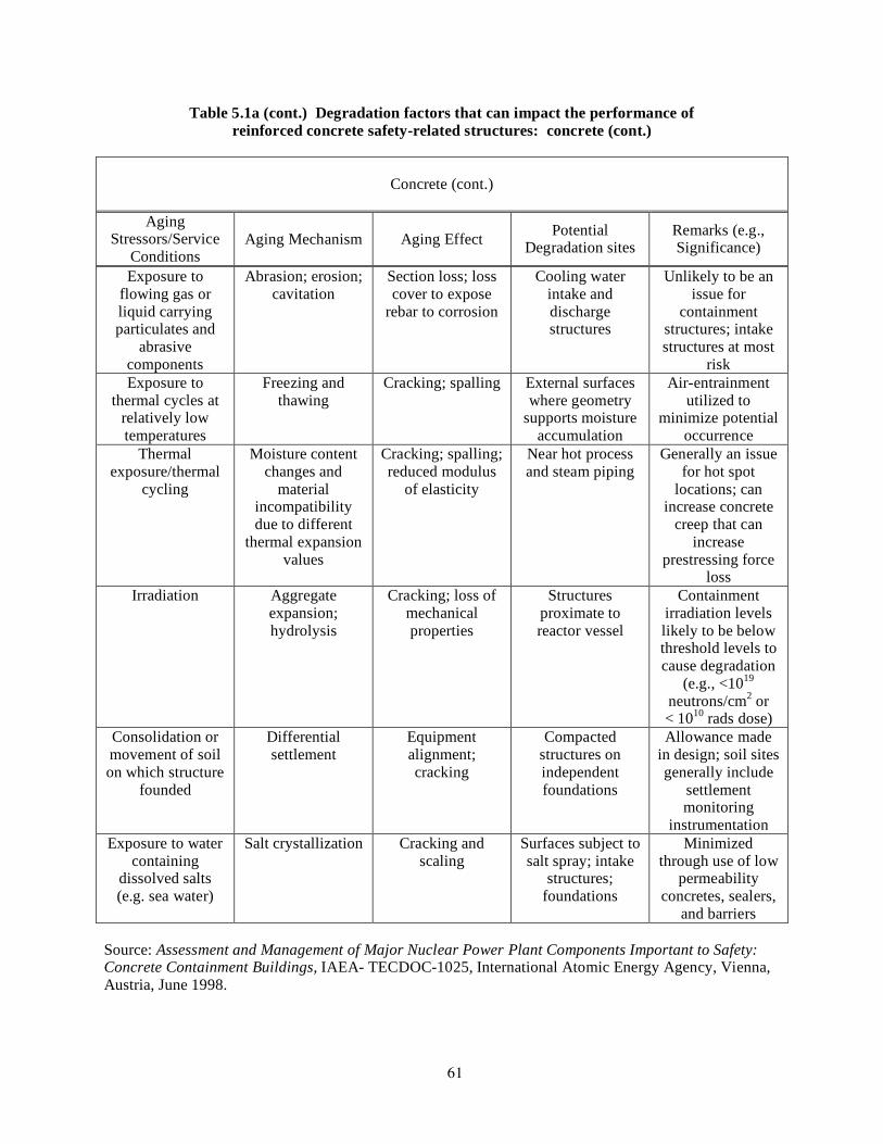
61
Table 5.1a (cont.) Degradation factors that can impact the performance of reinforced concrete safety-related structures: concrete (cont.)
Concrete (cont.)
Aging Stressors/Service
Conditions Aging Mechanism Aging Effect Potential
Degradation sites Remarks (e.g., Significance)
Exposure to flowing gas or liquid carrying particulates and
abrasive components
Abrasion; erosion; cavitation
Section loss; loss cover to expose
rebar to corrosion
Cooling water intake and discharge structures
Unlikely to be an issue for
containment structures; intake structures at most
risk Exposure to
thermal cycles at relatively low temperatures
Freezing and thawing
Cracking; spalling External surfaces where geometry
supports moisture accumulation
Air-entrainment utilized to
minimize potential occurrence
Thermal exposure/thermal
cycling
Moisture content changes and
material incompatibility due to different
thermal expansion values
Cracking; spalling; reduced modulus
of elasticity
Near hot process and steam piping
Generally an issue for hot spot
locations; can increase concrete
creep that can increase
prestressing force loss
Irradiation
Aggregate expansion; hydrolysis
Cracking; loss of mechanical properties
Structures proximate to reactor vessel
Containment irradiation levels likely to be below threshold levels to cause degradation
(e.g., <1019 neutrons/cm2 or < 1010 rads dose)
Consolidation or movement of soil on which structure
founded
Differential settlement
Equipment alignment; cracking
Compacted structures on independent foundations
Allowance made in design; soil sites generally include
settlement monitoring
instrumentation Exposure to water
containing dissolved salts (e.g. sea water)
Salt crystallization Cracking and scaling
Surfaces subject to salt spray; intake
structures; foundations
Minimized through use of low
permeability concretes, sealers,
and barriers Source: Assessment and Management of Major Nuclear Power Plant Components Important to Safety: Concrete Containment Buildings, IAEA- TECDOC-1025, International Atomic Energy Agency, Vienna, Austria, June 1998.

62
Table 5.1b (cont.) Degradation factors that can impact the performance of reinforced concrete safety-related structures: reinforcing steel
Mild Steel Reinforcement
Aging Stressors/Service
Conditions Aging Mechanism Aging Effect Potential
Degradation sites Remarks (e.g., Significance)
Depassivation of steel due to
carbonation or presence of chlorides
Composition or corrosion cells
leading to corrosion
Concrete cracking and spalling; loss of reinforcement
crosss-section
Outer layer of steel reinforcement in
all structures where cracks or
local defects (e.g., joints) are present
Prominent potential form of
degradation; leads to reduction of load-carrying
capacity Elevated
temperature
Microcrystalline changes
Reduction of yield strength and modulus of elasticity
Near hot process and steam piping
Of significance only where
temperatures exceed ~200˚C
Irradiation
Microstructural transformation
Increased yield strength; reduced
ductility
Structures proximate to reactor vessel
Irradiation levels likely to be below threshold levels to cause degradation
Cyclic loading
Fatigue Loss of bond to concrete; failure of
steel under extreme conditions
Equipment/piping supports
Localized damage; fatigue failure of
concrete structures unusual
Source: Assessment and Management of Major Nuclear Power Plant Components Important to Safety: Concrete Containment Buildings, IAEA- TECDOC-1025, International Atomic Energy Agency, Vienna, Austria, June 1998.
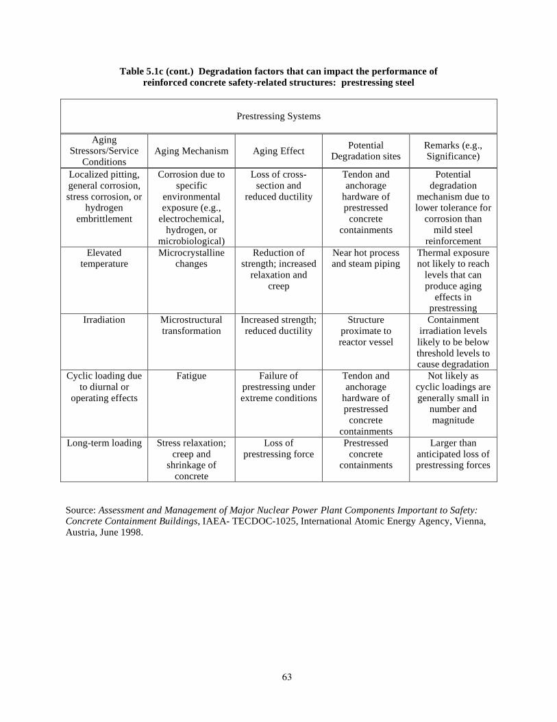
63
Table 5.1c (cont.) Degradation factors that can impact the performance of reinforced concrete safety-related structures: prestressing steel
Prestressing Systems
Aging Stressors/Service
Conditions Aging Mechanism Aging Effect Potential
Degradation sites Remarks (e.g., Significance)
Localized pitting, general corrosion, stress corrosion, or
hydrogen embrittlement
Corrosion due to specific
environmental exposure (e.g.,
electrochemical, hydrogen, or
microbiological)
Loss of cross-section and
reduced ductility
Tendon and anchorage
hardware of prestressed
concrete containments
Potential degradation
mechanism due to lower tolerance for
corrosion than mild steel
reinforcement Elevated
temperature
Microcrystalline changes
Reduction of strength; increased
relaxation and creep
Near hot process and steam piping
Thermal exposure not likely to reach
levels that can produce aging
effects in prestressing
Irradiation
Microstructural transformation
Increased strength; reduced ductility
Structure proximate to reactor vessel
Containment irradiation levels likely to be below threshold levels to cause degradation
Cyclic loading due to diurnal or
operating effects
Fatigue Failure of prestressing under extreme conditions
Tendon and anchorage
hardware of prestressed
concrete containments
Not likely as cyclic loadings are generally small in
number and magnitude
Long-term loading Stress relaxation; creep and
shrinkage of concrete
Loss of prestressing force
Prestressed concrete
containments
Larger than anticipated loss of prestressing forces
Source: Assessment and Management of Major Nuclear Power Plant Components Important to Safety: Concrete Containment Buildings, IAEA- TECDOC-1025, International Atomic Energy Agency, Vienna, Austria, June 1998.
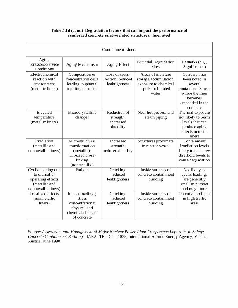
64
Table 5.1d (cont.) Degradation factors that can impact the performance of reinforced concrete safety-related structures: liner steel
Containment Liners
Aging Stressors/Service
Conditions Aging Mechanism Aging Effect Potential Degradation
sites Remarks (e.g., Significance)
Electrochemical reaction with environment
(metallic liners)
Composition or concentration cells leading to general
or pitting corrosion
Loss of cross-section; reduced
leaktightness
Areas of moisture storage/accumulation, exposure to chemical
spills, or borated water
Corrosion has been noted in
several containments near
where the liner becomes
embedded in the concrete
Elevated temperature
(metallic liners)
Microcrystalline changes
Reduction of strength; increased ductility
Near hot process and steam piping
Thermal exposure not likely to reach
levels that can produce aging effects in metal
liners Irradiation
(metallic and nonmetallic liners)
Microstructural transformation
(metallic); increased cross-
linking (nonmetallic)
Increased strength;
reduced ductility
Structures proximate to reactor vessel
Containment irradiation levels likely to be below threshold levels to cause degradation
Cyclic loading due to diurnal or
operating effects (metallic and
nonmetallic liners)
Fatigue Cracking; reduced
leaktightness
Inside surfaces of concrete containment
building
Not likely as cyclic loadings are generally
small in number and magnitude
Localized effects (nonmetallic
liners)
Impact loadings; stress
concentrations; physical and
chemical changes of concrete
Cracking; reduced
leaktightness
Inside surfaces of concrete containment
building
Potential problem in high traffic
areas
Source: Assessment and Management of Major Nuclear Power Plant Components Important to Safety: Concrete Containment Buildings, IAEA- TECDOC-1025, International Atomic Energy Agency, Vienna, Austria, June 1998.
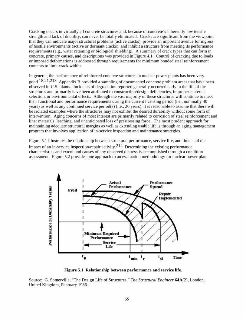
65
Cracking occurs in virtually all concrete structures and, because of concrete’s inherently low tensile strength and lack of ductility, can never be totally eliminated. Cracks are significant from the viewpoint that they can indicate major structural problems (active cracks); provide an important avenue for ingress of hostile environments (active or dormant cracks); and inhibit a structure from meeting its performance requirements (e.g., water retaining or biological shielding). A summary of crack types that can form in concrete, primary causes, and descriptions was provided in Figure 4.1. Control of cracking due to loads or imposed deformations is addressed through requirements for minimum bonded steel reinforcement contents to limit crack widths. In general, the performance of reinforced concrete structures in nuclear power plants has been very good.18,21,213 Appendix B provided a sampling of documented concrete problem areas that have been observed in U.S. plants. Incidents of degradation reported generally occurred early in the life of the structures and primarily have been attributed to construction/design deficiencies, improper material selection, or environmental effects. Although the vast majority of these structures will continue to meet their functional and performance requirements during the current licensing period (i.e., nominally 40 years) as well as any continued service period(s) (i.e., 20 years), it is reasonable to assume that there will be isolated examples where the structures may not exhibit the desired durability without some form of intervention. Aging concerns of most interest are primarily related to corrosion of steel reinforcement and liner materials, leaching, and unanticipated loss of prestressing force. The most prudent approach for maintaining adequate structural margins as well as extending usable life is through an aging management program that involves application of in-service inspection and maintenance strategies. Figure 5.1 illustrates the relationship between structural performance, service life, and time, and the impact of an in-service inspection/repair activity.214 Determining the existing performance characteristics and extent and causes of any observed distress is accomplished through a condition assessment. Figure 5.2 provides one approach to an evaluation methodology for nuclear power plant
Figure 5.1 Relationship between performance and service life.
Source: G. Somerville, “The Design Life of Structures,” The Structural Engineer 64A(2), London, United Kingdom, February 1986.
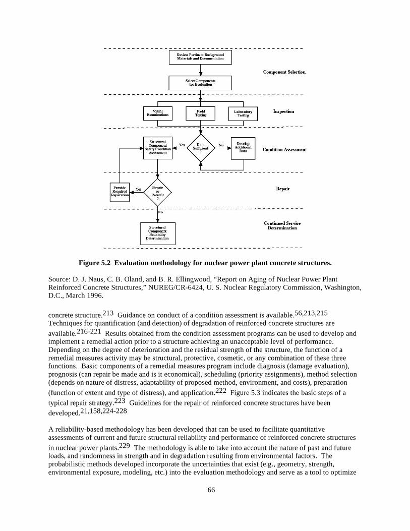
66
Figure 5.2 Evaluation methodology for nuclear power plant concrete structures.
Source: D. J. Naus, C. B. Oland, and B. R. Ellingwood, “Report on Aging of Nuclear Power Plant Reinforced Concrete Structures,” NUREG/CR-6424, U. S. Nuclear Regulatory Commission, Washington, D.C., March 1996. concrete structure.213 Guidance on conduct of a condition assessment is available.56,213,215 Techniques for quantification (and detection) of degradation of reinforced concrete structures are available.216-221 Results obtained from the condition assessment programs can be used to develop and implement a remedial action prior to a structure achieving an unacceptable level of performance. Depending on the degree of deterioration and the residual strength of the structure, the function of a remedial measures activity may be structural, protective, cosmetic, or any combination of these three functions. Basic components of a remedial measures program include diagnosis (damage evaluation), prognosis (can repair be made and is it economical), scheduling (priority assignments), method selection (depends on nature of distress, adaptability of proposed method, environment, and costs), preparation (function of extent and type of distress), and application.222 Figure 5.3 indicates the basic steps of a typical repair strategy.223 Guidelines for the repair of reinforced concrete structures have been developed.21,158,224-228 A reliability-based methodology has been developed that can be used to facilitate quantitative assessments of current and future structural reliability and performance of reinforced concrete structures in nuclear power plants.229 The methodology is able to take into account the nature of past and future loads, and randomness in strength and in degradation resulting from environmental factors. The probabilistic methods developed incorporate the uncertainties that exist (e.g., geometry, strength, environmental exposure, modeling, etc.) into the evaluation methodology and serve as a tool to optimize
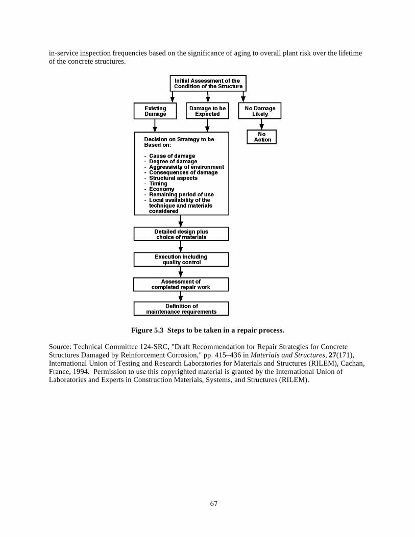
67
in-service inspection frequencies based on the significance of aging to overall plant risk over the lifetime of the concrete structures.
Figure 5.3 Steps to be taken in a repair process.
Source: Technical Committee 124-SRC, "Draft Recommendation for Repair Strategies for Concrete Structures Damaged by Reinforcement Corrosion," pp. 415–436 in Materials and Structures, 27(171), International Union of Testing and Research Laboratories for Materials and Structures (RILEM), Cachan, France, 1994. Permission to use this copyrighted material is granted by the International Union of Laboratories and Experts in Construction Materials, Systems, and Structures (RILEM).

68

69
6 REFERENCES
1. B. Mather, "Concrete Need Not Deteriorate," pp. 32–37 in Journal of American Concrete Institute, 1(9), Detroit, Michigan, September 1979.
2. ACI Committee 201, "Guide to Durable Concrete," pp. 573–609 in Journal of American Concrete Institute, 74(12), Farmington Hills, Michigan, December 1977.
3. Concrete - Guide to Specifying Concrete, BS 5328, British Standards Institution, London, United Kingdom, 1997.
4. Structural Use of Concrete – Code of Practice for Design and Construction, BS 8110, British Standards Institution, London, United Kingdom, 1985.
5. Building Code Requirements for Structural Concrete and Commentary, ACI Standard 318-05, American Concrete Institute, Farmington Hills, Michigan, November 2005.
6. Concrete – Complementary British Standard to BS EN 206-1, BS 8500, British Standards Institution, London, United Kingdom, 2002.
7. Durable Concrete Structures — Design Guide, Comite Euro-International de Beton, Thomas Telford Service Publisher, London, England, 1992.
8. P-C. Aïtcin, “Cements of Yesterday and Today - Concrete of Tomorrow,” Cement and Concrete Research 30, pp. 1249-1359, Elsevier Science Ltd., 2000.
9. U. S. Nuclear Regulatory Commission, Issuance of Final Amendment to 10 CFR §50.55a to Incorporate by Reference the ASME Boiler and Pressure Vessel Code (ASME Code), Section XI, Subsection IWE and Subsection IWL, SECY-96-080, Washington, D.C., 1996.
10. P. K. Mehta, “Greening of the Concrete Industry for Sustainable Development, Concrete International 24, pp. 23-28, American Concrete Institute, Farmington Hills, Michigan, July 2002.
11. Department of Materials Science and Engineering, University of Illinois, Urbana, Illinois: http://matse1.mse.uiuc.edu/~tw/concrete/time.html
12. L. G. Mallinson and I. Ll. Davies, A Historical Examination of Concrete, EUR 10937 EN, Commission of European Communities, Luxembourg, 1987.
13. J. Fraczek, "ACI Survey of Concrete Structure Errors," pp. 14–20 in Journal of American Concrete Institute, Vol. 1(12), Farmington Hills, Michigan, December 1979.
14. R. Hauser, "Lessons Learned from European Failures," pp. 21–25 in Journal of American Concrete Institute, Vol. 1(12), Farmington Hills, Michigan, December 1979.
15. “Report Card for America’s Infrastructure,” American Society of Civil Engineers, New York, New York, 2005.
16 P. K. Mehta, “Reducing the Environmental Impact of Concrete,” Concrete International 23(10), pp. 61-66, American Concrete Institute, Farmington Hills, Michigan, October 2001.
17. P. K. Mehta and R. W. Burrows, “Building Durable Structures in the 21st Century,” Concrete International 23(3), pp. 57-63, American Concrete Institute, Farmington Hills, Michigan, March 2001.
18. Assessment and Management of Major Nuclear Power Plant Components Important to Safety: Concrete Containment Buildings, IAEA-TECDOC-1025, International Atomic Energy Agency, Vienna, Austria, June 1998.
19. H. Ashar and G. Bagchi, “Assessment of Inservice Conditions or Safety-Related Nuclear Plant Structures,” NUREG-1522, U. S. Nuclear Regulatory Commission, Washington, D.C., June 1995.
20. An International Survey of In-Service Inspection Experience with Prestressed Concrete Pressure Vessels and Containments for Nuclear Reactors, FIP/3/5, Fédération Internationale de la Précontrainte, Wexham Springs, Slough, England, April 1982.
21. P. D. Krauss, Repair Materials and Techniques for Concrete Structures in Nuclear Power Plants, ORNL/NRC/LTR-93/28, Martin Marietta Energy Systems, Inc., Oak Ridge National Laboratory, Oak Ridge, Tennessee, May 1994.

70
22. J. H. Willenbrock et al., Final Summary Report : A Comparative Analysis of Structural Concrete Quality Assurance Practices of Nine Nuclear and Three Fossil Fuel Plant Construction Projects, Report No. C00/4120-3, Department of Civil Engineering, The Pennsylvania State University, University Park, Pennsylvania, December 1978.
23. fib Task Group 1.3, Containment Structures, “Nuclear Containments – State-of-the-Art Report,” Bulletin 13, International Federation for Structural Concrete (fib), Federal Institute of Technology, Lausanne, Switzerland, 2001.
24. ACI Committee 221, “Guide for Use of Normal Weight and Heavyweight Aggregates in Concrete,” ACI 221R-96, American Concrete Institute, Farmington Hills, Michigan, 2001.
25. ACI Committee E-701, “Cementitious Materials for Concrete,” ACI Education Bulletin E3-01, American Concrete Institute, Farmington Hills, Michigan, 2001.
26. ACI Committee 212, “Chemical Admixtures for Concrete,” ACI 212.3R-04, American Concrete Institute, Farmington Hills, Michigan, 2004.
27. “Portland Cement: Past and Present,” Concrete Technology Today 17(2), pp. 1-4, Portland Cement Association, Skokie, Illinois, July 1996.
28. “The Structural Use of Reinforced Concrete in Buildings,” CP 114, Amendment 1, British Standards Institution, London, United Kingdom, 1965.
29. “Settlement Monitoring and Inspection of Plant Structures Affected by Degradation of Porous Concrete,” NRC Information Notice 98-26, U. S. Nuclear Regulatory Commission, Washington, D.C., 1998.
30. G. Troxell et al., Composition and Properties of Concrete, McGraw-Hill, New York, New York, 1968.
31. "Standard Specification for Portland Cement," ASTM C150-05, ASTM International, American Society of Testing and Materials, West Conshohocken, Pennsylvania, 2005.
32. "Standard Specification for Carbon Structural Steel," ASTM A 36/A 36M-05, Ibid. 33. "Standard Specification for Deformed and Plain Carbon Steel Bars for Concrete Reinforcement,"
ASTM A 615/ A 615M-06, Ibid. 34. "Standard Specification for Low-Alloy Steel Deformed and Plain Bars for Concrete
Reinforcement," ASTM A 706/ A 706M-06, Ibid. 35. "Standard Specificaion for Deformed Billet-Steel Bars for Concrete Reinforcement with
60,000 psi Minimum Yield Strength (discontinued 1968)," ASTM A 432, Ibid. 36. "Standard Specification for Minimum Requirements for the Deformations of Deformed Steel
Bars for Concrete Reinforcement (superseded)," ASTM A 305, Ibid. 37. "Standard Specification for Uncoated Stress-Relieved Steel Wire for Prestressed Concrete,"
ASTM A 421/ A 421M-05, Ibid. 38. "Standard Specification for Steel Strand, Uncoated Seven-Wire for Prestressed Concrete," ASTM
A 416/ A416M-05, Ibid. 39. "Standard Specification for Uncoated High-Strength Steel Bars for Prestressing Concrete,"
ASTM A 722/ A 722M-05, Ibid. 40. "Standard Specification for Steel Bar, Carbon and Alloy, Cold-Finished," ASTM A 108-03, Ibid. 41. "Standard Specification for Pressure Vessel Plates, Carbon Steel, for Moderate- and Lower-
Temperature Service," ASTM A 516/ A516M-06, Ibid. 42. "Standard Specification for Stainless Steel Bars and Shapes," ASTM A 276-06, Ibid. 43. "Standard Specification for Carbon and Alloy Steel Bars Subject to End-Quench Hardenability
Requirements," ASTM A 304-05, Ibid. 44. "Standard Specification for Pressure Vessel Plates, Carbon Steel, Low- and Intermediate-Tensile
Strength," ASTM A 285/ A 285M-03, Ibid. 45. "Standard Specification for Pressure Vessel Plates, Heat-Treated, Carbon-Managanese-Silicon
Steel," ASTM A 537/ A 537M-06, Ibid. 46. D. W. Hobbs, “Concrete Deterioration: Causes, Diagnosis, and Minimising Risk,” International
Materials Reviews 46(3), pp. 117-144, 2001.

71
47. U.S. Army Corps of Engineers, “Evaluation and Repair of Concrete Structures – Engineering Manual,” EM 1110-2-2-2002, Waterways Experiment Station, Vicksburg, Mississippi, 1995.
48. D. J. Naus, Concrete Component Aging and Its Significance Relative to Life Extension of Nuclear Power Plants, NUREG/CR-4652 (ORNL/TM-10059), Martin Marietta Energy Systems, Inc., Oak Ridge National Laboratory, Oak Ridge, Tennessee, September 1986.
49. Class I Structures License Renewal Industry Report: Revision 1, EPRI TR-103842 (NUMARC 90-06), Electric Power Research Institute, Palo Alto, California, July 1994.
50. C. J. Hookham and V. N. Shah, Insights for Aging Management of Major Light Water Reactor Components, Vol. 2 – Reinforced and Prestressed Concrete Containments, NUREG/CR-5314 (EGG-2562), Idaho National Engineering Laboratory, Idaho Falls, Idaho, July 1994 (draft).
51. PWR Containment Structures License Renewal Industry Report: Revision 1, EPRI TR-103835 (NUMARC 90-01), Electric Power Research Institute, Palo Alto, California, July 1994.
52. V. N. Shah et al., "Boiling Water Reactor Containments," Chapter 9 in Residual Life Assessment of Major Light Water Reactor Components-Overview Volume 2, NUREG/CR-4731 (EGG-2469, Vol. 2), Idaho National Engineering Laboratory, Idaho Falls, Idaho, November 1989.
53. F. E. Gregor and C. J. Hookham, "Remant Life Preservation of LWR Plant Structures," pp. 453–459 in Transactions of the 12th International Conference on Structural Mechanics in Reactor Technology held August 15–20, 1993, in Stuttgart, Germany, Paper DH06/2, Elsevier Science Publishers, Amsterdam, The Netherlands, 1993
54. J. Kropp, “Relations Between Transport Characteristics and Durability,” in Performance Criteria for Concrete Durability, J. Kropp and H.K. Hilsdorf (editors), RILEM Report No.12, pp. 97-133, E & FN Spon Publishers, London, United Kingdom, 1995.
55. N. Buenfield, “Measuring and Modelling Transport Phenomena in Concrete for Life Prediction of Structures,” Chapter 5 in Prediction of Concrete Durability, J. Glanville and A. Neville (editors), E & FN Spon Publishers, London, United Kingdom, 1997.
56. Diagnosis of Deterioration in Concrete Structures – Identification of Defects, Evaluation and Development of Remedial Action, Technical Report No. 54, The Concrete Society, Century House, Berkshire, United Kingdom, 2000.
57. H.-U. Litzner and A. Baker, “Design of Concrete Structures for Durability and Strength to Eurocode 2,” Materials and Structures 32, pp. 323-330, June 1999.
58. Non-Structural Cracks in Concrete, Technical Report 22, Concrete Society, London, England, 1982.
59. RILEM Committee 104-DDC, "Draft Recommendations for Damage Classification of Concrete Structures," pp. 362–369 in Materials and Structures 27, International Union of Testing and Research Laboratories for Materials and Structures, Cachan, France, 1994.
60. L. Bucea, R. Khatri, and V. Sirivivatnanon, “Chemical and Physical Attack of Salts on Concrete,” Urban Salt 2005 Conference, Riverside Theatre, Parramatta, Australia, 8-9 February 2005.
61. T. A. Harrison, J. D. Dewer, and R. V. Brown, “Freeze-Thaw Resisting Concrete – Its Achievement in the UK,” CIRIA C559, Concrete Society, London, United Kingdom, 2001.
62. S. Mindess and J. F. Young, Concrete, Prentice-Hall, Inc., Englewood Cliffs, New Jersey, 1981. 63. A. M. Neville, Properties of Concrete, John Wiley and Sons, Inc., New York, New York, 1996. 64. American Concrete Institute Committee 201, “Guide to Durable Concrete,” ACI 201.2R-01,
American Concrete Institute, Farmington Hills, Michigan, 2001. 65. Concrete Materials and Methods of Concrete Construction, CAN/CSA – A23.1, Appendix B,
Canadian Standards Association, Toronto, Canada, 2004. 66. J. E. McDonald, “An Evaluation of Materials for Repair of Erosion Damage in Hydraulic
Structures,” High-Performance Materials and Systems Research Program, U.S. Army Corps of Engineers, Waterways Experiment Station, Vicksburg, Mississippi, 1980.
67. Guide to Concrete Repair, U.S. Department of the Interior, Bureau of Reclamation, Technical Services, Denver, Colorado. 1996.
68. ACI Committee 210, Erosion of Concrete in Hydraulic Structures, ACI 210R-93, American Concrete Institute, Farmington Hills, Michigan, 1998.

72
69. G. A. Khoury, “Performance of Heated Concrete—Mechanical Properties,” Contract NUC/56/3604A with Nuclear Installations Inspectorate, Imperial College, London, August 1996.
70. U. Schneider, Behaviour of Concrete at High Temperature, HEFT 337, Deutscher Ausschuss für Stahlbeton, Wilhelm Ernst & Sohn, Munich, Germany, 1982.
71. D. H. H. Quon, Phase Changes in Concrete Exposed to Sustained High Temperatures, Division Report MRP/MSL 80-111(TR), Mineral Sciences Laboratories, CANMET, Ottawa, Canada, August 1980.
72. J. F. Muir, “Response of Concrete Exposed to High Heat Flux on Surface,” Research Paper SAND 77-1467, Sandia National Laboratories, Albuquerque, New Mexico, 1977.
73. T. Y. Chu, “Radiant Heat Evolution of Concrete—A Study of the Erosion of Concrete Due to Surface Heating,” Research Paper SAND 77-0922, Sandia National Laboratories, Albuquerque, New Mexico, 1978.
74. G. Hildenbrand et al., “Untersuchung der Wechselvirkung von Kernschmelze und Reaktorbeton,” Abschlussbericht Förderungverhaben BMFT RS 154, KWU, Erlangen, Germany, May 1978.
75. U. Schneider, C. Diererichs, and C. Ehm, “Effect of Temperature on Steel and Concrete for PCRV’s,” Nuclear Engineering and Design 67, Elsevier Science Ltd., pp. 245–258, 1981.
76. S.Y. N. Chan, G-F. Peng, and J. K. W. Chan, “Comparison Between High Strength Concrete and Normal Strength Concrete Subjected to High Temperature,” Materials and Structures 29, pp. 616-619, RILEM, Cachan, France, 1996.
77. B. A. Surpenant, “Evaluating Fire-Damaged Concrete. Concrete and Reinforcing Steel Properties can be Compromised at Elevated Temperature,” Publication #R970020, Concrete Repair Digest, The Aberdeen Group, Addison, Illinois, 1997.
78. A. Sakar, P. N. Godbole, and, S. C. Chakrabarti, “Potential for Expert Systems in the Assessment and Repair of Fire Damaged Buildings in India,” Building Research and Information 24(1), Taylor & Francis Group, London, United Kingdom, 1996.
79. "Standard Practice for Petrographic Examination of Hardened Concrete," ASTM C 856-04, ASTM International, American Society of Testing and Materials, West Conshohocken, Pennsylvania, 2004.
80. D. M. Tucker and R. E. H. Read, “Assessment of Fire Damaged Structures,” IP 24/81, Building Research Establishment, Glasgow, Scotland, 1981.
81. R. Blundell, C. Diamond, and R. G. Browne, “The Properties of Concrete Subjected to Elevated Temperature,” CIRIA Underwater Engineering Group, Technical Note No. 9, Concrete Society, London, United Kingdom, 1976.
82. D. J. Naus, “The Effect of Elevated Temperature on Concrete Materials and Structures – A Literature Review,” NUREG/CR-6900, U.S. Nuclear Regulatory Commission, Washington, D.C., 2006.
83. “Assessment and Repair of Fire-Damaged Concrete Structures,” Technical Report No. 33, The Concrete Society, London, United Kingdom, 1990.
84. “Reliability of Fire-Damaged Structures,” Report No. 111, International Council for Building Research Studies and Documentation, Rotterdam, The Netherlands, 1989.
85. T. E. Uddin and C. G. Culver, “Effects of Elevated Temperature on Structural Materials,” Journal of Structural Division 101(7), pp. 1531-1549, American Society of Civil Engineers, New York, New York, 1975.
86. V. V. Bertero and M. Polivka, “Influence of Thermal Exposure on Mechanical Characteristics of Concrete,” SP-34, Concrete for Nuclear Reactors, Paper 28, American Concrete Institute, Farmington Hills, Michigan, 1972.
87. D. Campbell-Allen and P. M. Desai, “The Influence of Aggregate on the Behavior of Concrete at Elevated Temperature,” Nuclear Engineering and Design 6(1), Elsevier Science Ltd., pp. 65-77, August 1967.
88. H. L. Malhotra, “The Effect of Temperature on Compressive Strength of Concrete,” Magazine of Concrete Research 8(23), pp. 85-94, London, United Kingdom, 1956.

73
89. C. R. Cruz, “Elastic Properties of Concrete at High Temperature,” Journal Portland Cement Association – Research and Development Laboratories 8(1), pp. 37-45, Skokie, Illinois, 1966.
90. H. K. Hilsdorf et al., The Effects of Nuclear Radiation on the Mechanical Properties of Concrete, ACI SP-55, Douglas McHenry International Symposium on Concrete and Concrete Structures, American Concrete Institute, Detroit, Michigan, 1978.
91. M. F. Kaplan, Concrete Radiation Shielding – Nuclear Physics, Concrete Properties, Design, and Construction, John Wiley & Sons, New York, New York, 1989.
92. American Nuclear Society, Guidelines on the Nuclear Analysis and Design of Concrete Radiation Shielding for Nuclear Power Plants, American National Standard, ANSI/ANS-6.4-1985, La Grange Park, Illinois, 1985.
93. S. C. Alexander, “Effects of Irradiation on Concrete: Final Results,” Atomic Energy Research Establishment, Harwell, United Kingdom, 34 pp., 1963.
94. B. T. Price, C. C. Horton, and K. T. Spinney, “Radiation Shielding,” International Series of Monograph on Nuclear Energy, pp. 276-278, Pergamon Press, London, United Kingdom, 1957.
95. M. R. Elleuch, F. Dubois, and J. Rappenau, “Behavior of Special Shielding Concretes and of Their Constituents Under Neutron Irradiation,” Fourth United Nations International Conference on the Peaceful Uses of Atomic Energy, UN sales no.: 72.IX, 7 pp., International Atomic Energy Agency, Vienna, Austria, 1972.
96. J. A. Houben, “The Irradiation of Mortar Test Specimens,“ 2nd Conference on Prestressed Concrete Pressure Vessels and Their Thermal Insulation, pp. 170-183, Commission of European Communities, Brussels, Belgium, 1969.
97. B. Stôces, P. Otopal, V. Juricka, and J. Gabriel, “The Effect of Irradiation on the Mechanical Properties of Concrete,” Ceskoslovenska Akademie, Translated from the Czech, Oak Ridge National Laboratory Purchase Order 34B-83481, Letter Release No.: T81, STS No.: 14087, Oak Ridge, Tennessee.
98. A. W. Chisholm-Batten, “Effect of Irradiation on Strength of Concrete,” Atomic Energy Research Establishment Research Report AERE R 3332, 13 pp., United Kingdom Atomic Energy Authority, Harwell, 1960.
99. V. B. Dubrovskij, Sh.Sh. Ibragimov, A. Ya. Ladygin, and B. K. Pergamenshckik, “The Effect of Neutron Irradiation on Certain Properties of Refractory Concretes,” Atomnaya Energiya 21, pp. 108-112, 1966.
100. B. S. Gray, “The Effect of Reactor Radiation on Cements and Concrete,” Conference on Prestressed Concrete Pressure Vessels, pp. 17-39, Commission of European Communities, Luxembourg, Belgium, 1972.
101. C. F. Van der Schaaf, “Effect of Irradiation and Heating on the Strength of Mortar and Concrete,” 2nd Conference on Prestressed Concrete Pressure Vessels and Their Thermal Insulation, Commission of European Communities, Brussels, Belgium, 1969.
102. T. Ichikawa and H. Koizumi, “Possibility of Radiation-Induced Degradation of Concrete by Alkali-Silica Reaction of Aggregates,” Journal on Nuclear Science and Technology 39(8), pp. 880-884, Atomic Energy Society of Japan, Tokyo, August 2002.
103. F. Vodák, K. Trtík, V. Sopko, O. Kapicková, and P. Demo, “Effect of γ-Irradiation on Strength of Concrete for Nuclear Safety-Related Structures,” Cement and Concrete Research 35, pp. 1447-1551, Elsevier Ltd., 2005.
104. American Society of Mechanical Engineers, “Code for Concrete Reactor Vessels and Containments,” Section III, Division 2 of ASME Boiler and Pressure Vessel Code, ACI Standard 359, New York, New York, 2005.
105. British Standards Institution, Specification for Prestressed Concrete Pressure Vessels for Nuclear Reactors, BS 4975, London, United Kingdom, 1973.
106. Science Applications, Inc., Study of Radiation Dosage to Structural Components in Nuclear Reactors, EPRI NP-152, Electric Power Research Institute, Palo Alto, California, 1977.
107. ACI Committee 215, Considerations for Design of Concrete Structures Subjected to Fatigue, ACI 215R-92, American Concrete Institute, Farmington Hills, Michigan, 1992.

74
108. S. P. Shah (ed.), Fatigue of Concrete Structures, SP-75, American Concrete Institute, Farmington Hills, Michigan, 1982.
109. P. K. Mehta, Concrete - Structure, Properties, and Materials, Prentice-Hall, Inc., Englewood Cliffs, New Jersey, 1986.
110. P. K. Mehta and B. C. Gerwick, Jr., "Cracking-Corrosion Interaction in Concrete Exposed to Marine Environment," pp. 45–51 in Concrete International 4(10), American Concrete Institute, Farmington Hills, Michigan, October 1982.
111. A. Neville, “Efflorescence – Surface Blemish or Internal Problem? Part 1: The Knowledge” pp. 85 – 88 in Concrete International 24(10), American Concrete Institute, Farmington Hills, Michigan, September 2002.
112. Concrete Slab Surface Defects – Causes, Prevention, Repair, PCA R&D Serial No. 2155, Portland Cement Association, Skokie, Illinois, 1997.
113. T. Ekström, “Leaching of Concrete - The Leaching Process and Its Effects,” Report TVBM-1020, Doctoral Thesis, Division of Building Technology, Lund Institute of Technology, Lund, Sweden, 2003.
114. U. Halvorsen, “Corrosion of Steel and Leaching of Lime Near Cracks in Concrete Structures,” Bulletin 1, Division of Building Technology, Lund Institute of Technology, Lund, Sweden, 1966.
115. C. Trinh, L. Bucea, and O. Ferguson, “Sulphate Resistance of Cementitious Materials – Mechanisms, Deterioration Processes, Testing and the Influence of Binder,” Proc. Concrete 97, pp. 263-268, Concrete Institute of Australia, Adelaide, May 1997.
116. Concrete Materials and Methods of Concrete Structures, CAN/CSA – A23.1, Appendix B, Canadian Standards Association, Toronto, 1990.
117. Assessment of Water, Soil, and Gases for Their Aggressiveness to Concrete; Collection and Examination of Water and Soil Samples, Deutsches Institute für Normung ev. Beton- und Stahlbetonbau, Deutscher Ausschus für Stahlbeton, Beuth Verlag GmbH, Berlin, Germany, 1991.
118. Concrete Resistant to Chemical Attack, BS EN 206-1/BS 8500, British Standards Institution, London, United Kingdom, October 2001.
119. E. G. Swenson, “Concrete in Sulphate Environments,” CBD-136, Canadian Building Digest, National Research Council, Ottawa, Canada, September 1999.
120. Thaumasite Expert Group, “Thaumasite Expert Group One-Year Review,” Concrete 34(6), pp. 51-53, June 2000.
121. R. C. Mielenz, S. L. Marusin, W. G. Hime, and Z. T. Jugovic, “Investigation of Prestressed Concrete Railway Tie Distress,” Concrete International 17(12), American Concrete Institute, Farmington Hills, Michigan, 1995.
122. R. L. Day, “The Effect of Secondary Ettringite Formation on the Durability of Concrete: A Literature Analysis,” Research and Development Bulletin RD108T, Portland Cement Association, Skokie, Illinois, 1992.
123. “Types and Causes of Concrete Deterioration,” Concrete Information IS536, Portland Cement Association, Skokie, Illinois, 2002.
124. ACI Committee 515, “A Guide for Use in Waterproofing, Dampproofing, Protective, and Decorative Barrier Systems for Concrete,” ACI 515.1R-79, American Concrete Institute, Farmington Hills, Michigan, 1979.
125. “Appendix A – Distress Mechanisms” to Guidelines to Detection, Analysis, and Treatment of Material-Related Distress in Concrete Pavements, FHWA-RD-01-163, U.S. Department of Transportation, Federal Highway Administration, Washington, D.C., March 2002.
126. M. A. Ozol, "Alkali-Carbonate Rock Reactions." Significance of Tests and Properties of Concrete and Concrete-Making Materials, pp. 341-364 in ASTM STP 169C, American Society of Testing and Materials, West Conshohocken, Pennsylvania, 1994.
127. J. A. Farny, and S. H. Kosmatka, “Diagnosis and Control of Alkali-Aggregate Reactions in Concrete,” Concrete Information Series No. IS413.01T, 24. pp., Portland Cement Association, Skokie, Illinois, 1997.

75
128. M. L. Leming, "Alkali–Silica Reactivity: Mechanisms and Management." Mining Engineering 48(12), pp. 61-64, 1996.
129. Appendix B to Concrete Material and Methods of Concrete Construction, CAN/CSA -A23.1, Canadian Standards Association, Toronto, 2000.
130. R. N. Swamy, “Structural Implications of Alkali Silica Reaction,” Proc. Of 8th International Conference on Alkali-Aggregate Reaction, Kyoto, Japan, Elsevier Applied Science Ltd,, London, United Kingdom, 1989.
131. K. Ono, “Damaged Concrete Structures in Japan Due to Alkali Silica Reaction,” International Journal of Cement Composites and Lightweight Concrete 10(4), p. 247, 1988.
132. D. W. Hobbs, Alkali-Silica Reaction in Concrete, Thomas Telford Ltd., London, United Kingdom, 1988.
133. BRITE/EURAM, “The Residual Service Life of Reinforced Concrete Structures,”BREU-CT92-0591, Project 4062, BRITE/EURAM Programme, Commission of European Communities, Brussels, Belgium, 1995.
134. T. Ahmed, E. Burley, and R. S. Rigden, “The Effect of Alkali-Silica Reaction on the Fatigue Behavior of Plain Concrete in Compression, Indirect Tension, and Flexure,” Magazine of Concrete Research 51(6), pp. 375-390, December 1999.
135. P. Chandra and G. A. Korobokis, “Bond Strength of Reinforcement in Concrete Affected by ASR,” Contractor Report No. 233, Transport and Research Laboratory, London, United Kingdom, 1991.
136. Y. Majlesi, “A Laboratory Investigation Into Structural Performance and Mechanical Properties of Plain and Reinforcing Concrete Elements Affected by ASR,” PhD Thesis, QMW - University of London, United Kingdom, 1994.
137. A. E. K. Jones and L. A. Clark, “The Effects of ASR on the Properties of Concrete and the Implications of Assessment, “ Engineering Structures 20(9), pp. 785-791 Elsevier Science Ltd., London, United Kingdom, 1998.
138. M. Kawamura, K. Takemoto, and M. Ichise, “Influences of Alkali-Silica Reaction On Steel Reinforcement in Concrete,” pp. 115-120 in Proc. of 8th International Conference on Alkali-Aggregate Reaction, Kyoto, Japan, Elsevier Applied Science Ltd., London, United Kingdom, 1989.
139. Alkali-Silica Reaction: Minimising the Risk of Damage to Concrete, Technical Report No. 30, Concrete Society, London, United Kingdom, 1999.
140. American Concrete Institute Committee 221, "State-of-the-Art Report on Alkali-Aggregate Reactivity." ACI 221.1R-98, American Concrete Institute, Farmington Hills, Michigan, 1998.
141. D. Stark, B. Morgan, P. Okamoto, and S. Diamond, “Eliminating or Minimizing Alkali-Silica Reactivity,” SHRP-C-343, Strategic Highway Research Program, Washington, D.C., 1993.
142. K. J. Folliard, M. D. A. Thomas, and K. E. Kurtis, “Guidelines for the Use of Lithium to Mitigte or Prevent Alkali-Silica Reaction (ASR),”FHWA-RD-03-047, Federal Highway Administration, Washingtion, D.C., July 2003.
143. A. Neville, Neville on Concrete – An Examination of Issues in Concrete Practice, American Concrete Institute, Farmington Hills, Michigan, 2003.
144. D. J. Naus, L. R. Dole, and C. H. Mattus, “Interim Report: Assessment of Potential Phosphate Ion-Concrete Interactions,” Oak Ridge National Laboratory Letter Report to Mr. H. L. Graves, III, U. S. Nuclear Regulatory Commission, Washington, D.C., August 26, 2005.
145. C. H. Mattus, L. R. Dole, and D. J. Naus, Laboratory Investigation on Effect of Phosphate Ions on Concrete,” Attachment to Letter DJN/06-21, Subject: Transmittal of Letter Report on Laboratory Investigation of Phosphate Effects to Mr. H. L. Graves, III, U.S. Nuclear Regulatory Commission, Washington, D.C., April 21, 2006.
146. J. M. Horne and A. Meike, “Microbial Activity at Yucca Mountain,” UCRL-ID-122256, Lawrence Livermore National Laboratory, Livermore, California, September 25, 2005.
147. O. Aviam, G. Bar-Nes, Y. Zeiri, and A. Sivan, “Accelerated Biodegradation of Cement by Sulfur-Oxidizing Bacteria as a Bioassay for Evaluating Immobilization of Low-Level Radioactive Waste,” Applied and Environmental Microbiology 70(10), pp. 6031-6036, October 2004.

76
148. M. Diercks, W, Sand, and E. Bock, “Microbial Corrosion of Concrete,” Experientia 47, pp 514-516, 1991.
149. G. Morton, “Things that Go Rot in the Night – A Review of Biodegradation,” Microbiology Today 30 (21), August 2003.
150. R. Rogers, “Assessment of the Effects of Microbially Influenced Degradation on a Massive Concrete Structure,” Final Report to Introduced Materials Task, Yucca Mountain Site Characterization Project, 1995.
151. W. Sand and E. Bock, “Biodeterioration of Ceramic Materials by Biogenic Acid,” International Biodeterioration and Biodegeneration, Elsevier, pp 175-181, 1991.
152. ACI Committee 222, “Protection of Metals in Concrete Against Corrosion,” ACI 222R-01, American Concrete Institute, Farmington Hills, Michigan, 2001.
153. J. A. González, S. Feliu, S. Rodríguez, P. W. Ramírez, and C. Andrade, “Some Questions on the Corrosion of Steel in Concrete – Part 1: When, How and How Much Steel Corrodes,” Materials and Structures 29, pp. 40-46, January-February 1996.
154. I. Sims, “The Assessment of Concrete for Carbonation,” Concrete 28, pp. 33-38, November/December 1994.
155. B. Erlin, and G. J. Verbeck, “Corrosion of Metals in Concrete – Needed Research,” Corrosion of Metals in Concrete, SP-49, American Concrete Institute, Farmington Hills, Michigan, 1975.
156. J. A. González, C. Alonso, and C. Andrade, “Corrosion Rate of Reinforcements During Accelerated Carbonation of Mortar Made From Different Types of Cement,” Corrosion of Reinforcement in Concrete Construction, Society of Chemical Industry, pp. 159-174, Ellis Horwood, Chichester, England, 1983.
157. M. H. Roberts, “Carbonation of Concrete Made with Dense Natural Aggregates,” Information Paper 6/81, Building Research Establishment, Glasgow, Scotland, 1981.
158. P. Pullar-Strecker, Corrosion Damaged Concrete Assessment and Repair, Butterworths, London, United Kingdom, 1987.
159. R. T. L. Allen, and A. Forrester, “The Investigation and Repair of Damaged Reinforced Concrete Structures,” Corrosion of Reinforcement in Concrete Construction, Society of Chemical Industry, Ellis Horwood, Chichester, United Kingdom, 1983.
160. K. Kobayashi, K. Suzuki, and Y. Uno, “Carbonation of Concrete Structures and Decomposition of C-S-H,” Cement and Concrete Research 24(1), Elsevier Science Ltd., pp. 619-622, 1990.
161. E. J. Wallback, “The Performance of Concrete in Bridges – A Survey of 200 Highway Bridges,” HMSO, Department of Transport, London, United Kingdom, 1989.
162. H. Roper and D. Baweja, “Carbonation-Chloride Interactions and Their Influence on Corrosion Rates of Steel in Concrete,” in SP 126, Durability of Concrete – Second International Conference, Montreal, Canada, pp. 295-315, American Concrete Institute, Farmington Hills, Michigan, 1991.
163. J. R. Clifton, “Predicting the Remaining Service Life of Concrete,” NISTIR 4712, U.S. Department of Commerce, National Institue of Standards and Technology, Gaithersburg, Maryland, 1991.
164. RILEM, “Measurement of Hardened Concrete Carbonation Depth,” RILEM Recommendation CPC-18, Materials and Structures 21(126), pp. 453-455, Cachan, France, 1988.
165. S. Misra, and T. Uomoto, “Reinforcement Corrosion Under Simultaneous Diverse Exposure Conditions,” SP 126, Durability of Concrete – Second International Conference, Montreal, Canada, pp. 423-441, American Concrete Institute, Farmington Hills, Michigan, 1991.
166. R. Francois, and G. Arliguie, “Reinforced Concrete: Correlation Between Cracking and Corrosion,” in SP 126, Durability of Concrete – Second International Conference, Montreal, Canada, pp. 1221-1238, American Concrete Institute, Farmington Hills, Michigan, 1991.
167. Concrete Part 1: Specification, Performance, Production and Conformity, BS ENV 206–1, British Standards Institution, London, United Kingdom, 2000.

77
168. S. E. Hussain, A. S. Al-Gantani, and Rasheeduzzafar (1996) “Chloride Threshold for Corrosion of Reinforcement in Concrete,” ACI Materials Journal 93(6), pp.535-548, American Concrete Institute, Farmington Hills, Michigan, 1996.
169. J. A. González, E. Otero, S. Feliu, A. Bautista, E. Ramírez, and P. Rodríguez, “Some Considerations on the Effect of Chloride Ions on the Corrosion of Steel Reinforcement Embedded in Concrete Structures,” Magazine of Concrete Research 50(3), pp. 189-199, London, United Kingdom, 1998.
170. C. Arya, and L. A. Wood, “The Relevance of Cracking in Concrete to Corrosion of Reinforcement,” Technical Report No. 44, Concrete Society, Slough, Berkshire, United Kingdom, 1995.
171. “The Durability of Steel in Concrete: Part 2 – Diagnosis and Assessment of Corrosion-Cracked Concrete,” Building Research Establishment Digest 264, Building Research Station, Garston, Watford, United Kingdom, 1982.
172. Rasheeduzzafar, S. S. Al-Saadoun, and A. S. Al-Gahtani, “Corrosion Cracking In Relation to Bar Diameter, Cover, and Concrete Quality,” Journal of Materials in Civil Engineering 4(4), pp. 327-341, American Society of Civil Engineers, New York, New York, November 1992.
173. G. J. Al-Sulaimani, M. Kaleemullah, I. A. Basunbul, and Rasheeduzzafar, “Influence of Corrosion and and Cracking on Bond Behavior and Strength of Reinforced Concrete Members,” ACI Structural Journal 87(2), pp. 220-231, American Concrete Institute, Farmington Hills, Michigan, 1990.
174. S. Morinaga, “Prediction of Service Lives of Reinforced Concrete Buildings Based on the Corrosion Rate of Reinforcing Steel,” Durability of Building Materials and Components, E.&F. N Spon., London, United Kingdom, 1990.
175. J. Rodriguez, L. M. Ortega, J. Casal, and J. M. Diez, “Corrosion of Reinforcement and Service Life of Concrete Structures,” 7th International Conference on the Durability of Building Materials and Components, Stockholm, Sweden, 1996.
176. C. Andrade, C. Alonso, D. Garcia, and J. Rodríguez, “Remaining Lifetime of Reinforced Concrete Structures: Effect of Corrosion on the Mechanical Properties of Steel,” International Conference on Life Prediction of Corrodible Structures, pp. 12/1-12/11, National Association of Corrosion Engineers, Cambridge, United Kingdom, 1991
177. S. Morinaga, “Prediction of Service Lives of Reinforced Concrete Buildings Based on Rate of Corrosion of Reinforcing Steel,” Special Report of Institute of Technology Shimizu Corporation 23, Japan, June 1988.
178. L. Amleh and S. Mirza, “Corrosion Influence on Bond Between Steel and Concrete,” ACI Structural Journal 96(3), American Concrete Institute, Farmington Hills, Michigan, 1996.
179. P. S. Mangat and M. S. Elgarf, “Bond Characteristics of Corroding Reinforcement in Concrete Beams, Materials and Structures 32(216), pp. 89-97, RILEM, Cachan, France, 1996.
180. RILEM/CEB/FIP, “Bond Test for Reinforcing Steel,” Materials and Structures 6(32), RILEM, Cachan, France, 1973.
181. C. Fang, K. Gylltoft, K. Lundgren, and M. Plos, “Effect of Corrosion on Bond in Reinforced Concrete Under Cyclic Loading,” Cement and Concrete Research 36, pp. 548-555, Elsevier Ltd., 2006.
182. Manual of Steel Construction, 8th Edition, pp. 6.4-6.6, American Institute of Steel Construction, Chicago, Illinois, 1980.
183. H. L. Malhotra, “Design of Fire-Resistant Structures,” pp. 67, 73, and 78, Chapman and Hall, New York, New York, 1982.
184. W. T. Edwards and W. L. Gamble, “Strength of Grade 60 Reinforcing Bars After Exposure to Fire Temperatures,” Concrete International 8(10), pp. 17-19, American Concrete Institute, Farmington Hills, Michigan, October 1986.
185. O. El-Nesr, “Diagnosis and Repair of Buildings Damaged by Fire Exposure,” Extending the Lifespan of Structures, IABSE Symposium San Francisco, International Association of Bridge and Structural Engineers, Zurich, Switzerland, 1995.
78
186. P. Smith, “Resistance to High Temperatures,” Significance of Tests and Properties of Concrete and Concrete-Making Materials, STP 169B, American Society for Testing and Materials, West Conshohocken, Pennsylvania, 1978.
187. M. Takeuchi et al., “Material Properties of Concrete and Steel Bars at Elevated Temperatures,” 12th International Conference on Structural Mechanics in Reactor Technology, Paper H04/4, pp. 13-138, Elsevier Science, North-Holland, Netherlands, 1993.
188. Comité Européen de Normalisation, Eurocode 2: Design of Concrete Structures, Part 1-2: Structural Fire Design,” ENV 1992- 1-2, Brussels, Belgium, 1995.
189. J.-C. Dotreppe, “Mechanical Properties of Quenched and Self-Tempered Reinforcing Steel at Elevated Temperatures Compared with Recommendations on Eurocode 1 – Part 1-2,” Materials and Structures 30, pp. 430-438, August-September 1997.
190. A. Cowen and R. W. Nichols, "Effect of Irradiation on Steels Used in Pressure Vessels," pp. 229–235 in Prestressed Concrete Pressure Vessels, Group D, Paper 20, Marilyn S. Udell (ed.), The Institute of Civil Engineers, London, England, 1968.
191. ACI Committee 215, Considerations for Design of Concrete Structures Subjected to Fatigue Loading, ACI 215R-74, American Concrete Institute, Farmington Hills, Michigan, 1997.
192. U. Nürnberber, “Corrosion Induced Failures of Prestressing Steel,” Otto-Graf Journal on Research and Testing 13, Otto-Graf-Institute (FMPA), University of Stuttgart, Germany, 2002.
193. W. H. Hartt, “A Critical Evaluation of Cathodic Protection for Prestressing Steel in Concrete,” pp. 515–524 in Proceedings of The Third International Symposium on Corrosion of Reinforcement in Concrete Construction held at Belfry Hotel in Wishaw, Warwickshire, United Kingdom, on May 21–24, 1990, Elsevier Applied Science, New York, New York, 1990.
194. J. Wagner, W. Young, S. Scheirer, and P. Fairer, Cathodic Protection Developments for Prestressed Concrete Components – Interim Report, Report No. FHWA-RD-92-056, Federal Highway Administration, Washington, D.C., March 1993.
195. R. F. Stratfull, "Criteria for the Cathodic Protection of Bridge Decks," Chapter 18 in Corrosion of Reinforcement in Concrete Construction, Society of Chemical Industry, London, United Kingdom, 1983
196. W. Podolny, Jr. and T. Melville, "Understanding the Relaxation in Prestressing," Prestressed Concrete Institute Journal, 14(4), Chicago, Illinois, August 1969.
197. M. S. Abrams and C. R. Cruz, The Behavior at High Temperature of Steel Strand for Prestressed Concrete, Research Department Bulletin No. 134, Portland Cement Association, Skokie, Illinois, 1961.
198. T. Z. Harmathy and W. W. Stanzack, Elevated Temperature Tensile and Creep Properties for Some Structural and Prestressing Steels, STP 464, American Society for Testing and Materials, West Conshohocken, Pennsylvania, 1970.
199. T. Cahill and G. D. Branch, "Long-Term Relaxation Behavior of Stabilized Prestressing Wires and Strands," Group D, Paper 19, pp. 219–228 in Prestressed Concrete Pressure Vessels, Marilyn S. Udell (ed.), The Institute of Civil Engineers, London, United Kingdom, 1968.
200. S. Freedman, "Properties of Materials for Reinforced Concrete," Handbook of Concrete Engineering, M. Fintel (ed.), Von Nostrand Reinhold Company, New York, New York, 1974.
201. J. R. Libby, Modern Prestressed Concrete-Design Principles and Construction Methods, Von Nostrand Reinhold Company, New York, New York, 1971.
202. J. A. Hanson, Prestress Loss as Affected by Type of Curing, Bulletin D75, Portland Cement Association, Skokie, Illinois, 1964.
203. PCI Committee on Prestress Losses, "Recommendations for Estimating Prestress Losses," Prestressed Concrete Institute Journal 20(5), Chicago, Illinois, 1975.
204. W. Podolny, Jr., "Understanding the Losses in Prestressing," Journal of the Prestressed Concrete Institute 14(5), Chicago, Illinois, 1969.
205. "Inservice Inspections of Ungrouted Tendons in Prestressed Concrete Containment Structures," Regulatory Guide 1.35, Rev. 3, Office of Standards Development, U.S. Nuclear Regulatory Commission, Washington, D.C., July 1990.

79
206. "Determining Prestressing Forces for Inspection of Prestressed Concrete Containments," Regulatory Guide 1.35.1, Office of Standards Development, U.S. Nuclear Regulatory Commission, Washington, D.C., July 1990.
207. W. Swiat et al., State-of-the-Art Report — Corrosion of Steel in Concrete, ORNL/NRC/LTR-93/2, Martin Marietta Energy Systems, Inc., Oak Ridge National Laboratory, Oak Ridge, Tennessee, May 1993.
208. Metals Handbook, ASM International, Ninth Edition, Vol. 13, Metals Park, Ohio, 1987. 209. M. Romanoff, Corrosion of Steel Pilings in Soils, Monograph 58, National Bureau of Standards,
Gaithersburg, Maryland, October 1962. 210. R. Peck, W. Hanson, and T. Thornburn, Foundation Engineering, Wiley and Sons, New York,
New York, 1974. 211. R. D. Browne, "Durability of Reinforced Concrete Structures," New Zealand Concrete
Construction, Parts 1 and 2, September and October 1989. 212. E. J. Gannon and P. D. Cady, Condition Evaluation of Concrete Bridges Relative to
Reinforcement Corrosion: State-of-the-Art of Existing Methods, SHRP-S-323, Vol. 1, Strategic Highway Research Program, National Research Council, Washington, D.C., 1993.
213. D. J. Naus, C. B. Oland, and B. R. Ellingwood, “Report on Aging of Nuclear Power Plant Reinforced Concrete Structures,” NUREG/CR-6424, U. S. Nuclear Regulatory Commission, Washington, D.C., March 1996.
214. G. Somerville, “The Design Life of Structures,” The Structural Engineer 64A(2), London, United Kingdom, February 1986.
215. ACI Committee 201, "Guide for Making a Condition Survey of Concrete In-Service," pp. 905–918 in Proceedings of American Concrete Institute 65(11), Farmington Hills, Michigan, November 1968.
216. ACI Committee 228, “In-Place Methods for Determination of Strength of Concrete,” ACI 228.1R-89, American Concrete Institute, Farmington Hills, Michigan, 1989.
217. ACI Committee 228, “Nondestructive Test Methods for Evaluation of Concrete in Structures,” ACI 228.2R-99, American Concrete Institute, Farmington Hills, Michigan, 1999.
218. V. M. Malhotra and N. J. Carino, Handbook of Nondestructive Testing of Concrete, CRC Press, Boca Raton, Florida, 1991.
219. H. S. Lew Nondestructive Testing, SP-112, American Concrete Institute, Farmington Hills, Michigan, 1988.
220. J. H. Bungey, Testing of Concrete in Structures, Third Edition, Surrey University Press, London, United Kingdom, 1996.
221. ACI Committee 349, “Evaluation of Existing Nuclear Safety-Related Concrete Structures,” ACI 349.3R, American Concrete Institute, Farmington Hills, Michigan, 1996.
222. J. J. Waddell, "Basic Steps of a Concrete Repair Program," pp. 30–33 in Concrete International, 2(9), American Concrete Institute, Farmington Hills, Michigan, September 1980.
223. Technical Committee 124-SRC, "Draft Recommendation for Repair Strategies for Concrete Structures Damaged by Reinforcement Corrosion," pp. 415–436 in Materials and Structures, 27(171), International Union of Testing and Research Laboratories for Materials and Structures (RILEM), Cachan, France, 1994.
224. Evaluation and Repair of Concrete Structures, EM-1110-2-2003, U.S. Army Corps of Engineers, Washington, D.C., 1986.
225. Repair of Concrete Damaged by Reinforcement Corrosion, Technical Report 26, Concrete Society, London, United Kingdom, 1984.
226. "Inspection and Maintenance of Reinforced and Prestressed Concrete Structures," FIP Guide to Good Practice, Fédération Internationale de la Précontrainte, Thomas Telford Publisher, London, United Kingdom, 1986.
227. P. H. Emmons, Concrete Repair and Maintenance Illustrated, RS Means Company, Inc., Kingston, Massachusetts, 1993.
80
228. REHABCON – Strategy for Maintenance and Rehabilitation in Concrete Structures, EC DG ENTR-C-2, Innovation and SME Programme, IPS-2000-0063, DG Enterprise, Commission of European Communities, Brussels, Belgium, May 2004.
229. B. R. Ellingwood, “Aging Effects on Probabilistic Risk Assessment,” NUREG/CR-6425, U. S. Nuclear Regulatory Commission, Washington, D.C., 1996.

81
APPENDIX A: SAFETY-RELATED CONCRETE STRUCTURES All commercial nuclear power plants in the U.S. contain concrete structures whose performance and function are necessary for protection of the safety of plant operating personnel and the general public, as well as the environment. The basic laws that regulate the design (and construction) of nuclear power plants are contained in Title 10 of the Code of Federal Regulations (CFR)A.1 that is clarified by Regulatory Guides (e.g., R.G. 1.29),A.2 NUREG reports, Standard Review Plans (e.g., Concrete and Steel Internal Structures of Steel or Concrete Containments),A.3 etc. In addition, R.G. 1.29 and Part 100 to Title 10 of the CFR state that nuclear power plant structures important to safety must be designed to withstand the effects of earthquakes without the loss of function or threat to public safety. These "safety-related" structures are designated as seismic Category I. Seismic Category I structures typically include those classified by the American Society of Mechanical Engineers (ASME) and the American Nuclear Society (ANS) as Safety Classes 1, 2, and 3 (i.e., safety related). Initially, existing building codes such as the American Concrete Institute (ACI) Standard 318, Building Code Requirements for Reinforced Concrete,A.4 were used in the nuclear industry as the basis for the design and construction of concrete structural members. However, because the existing building codes did not cover the entire spectrum of design requirements and because they were not always considered adequate, the U.S. Nuclear Regulatory Commission (USNRC) developed its own criteria for the design of Category I structures (e.g., definitions of load combinations for both operating and accident conditions). Current requirements for nuclear safety-related concrete structures, other than concrete reactor vessels and concrete containments, are also based on ACI 318, but have incorporated modifications to accommodate the unique performance requirements of nuclear power plants. These requirements were developed by ACI Committee 349 and first published in October 1976.A.5 This Code has been endorsed by the USNRC as providing an adequate basis for complying with the general design criteria for structures other than reactor vessels and containments.A.6 Reference A.7 provides additional information on the design of seismic Category I structures that are required to remain functional if the Safe Shutdown Earthquake (SSE) occurs. Current requirements for concrete reactor vessels and concrete containments were developed by ACI Committee 359 and first published in 1977.A.8 Supplemental load combination criteria are presented in Sect. 3.8.1 of the USNRC Regulatory Standard Review Plan.A.9 However, since all but one of the construction permits for existing NPPs have been issued prior to 1978, it is unlikely that endorsed versions of either ACI 349 or ACI 359 were used in the design of many of the concrete structures at these plants. Older plants that used early ACI codes, however, have been reviewed by the USNRC through the Systematic Evaluation Program to determine if there were any safety concerns.A.10 A myriad of concrete-based structures are contained as a part of a light-water reactor (LWR) plant to provide foundation, support, shielding, and containment functions. Table A.1 presents a listing of typical safety-related concrete structures that may be included as part of a LWR plant. Only a general description of these structures is provided in the following sections because detailed information of this type along with typical design parameters and operating conditions is provided elsewhere.A.11-A.15 Information pertaining to a particular structure at a plant of interest can be obtained from sources such as the plant's safety analysis report or docket file. Concrete structures that are considered to be "plant specific" or unique have not been addressed in the discussion below, but some information provided for similar structures may be applicable. Additionally, the names of certain structures may vary from plant-to-plant depending on the nuclear steam supply system (NSSS) vendor, architect-engineering firm, and owner preference. The safety-related concrete structures, for purposes of discussion, have been separated into two categories — typical plant structures and auxiliary structures.
82
A.1 Typical Plant Structures A.1.1 Boiling-Water Reactors Typical safety-related concrete structures contained in boiling-water reactor (BWR) plants can be grouped into four general categories: primary containments, containment internal structures, secondary containments/reactor buildings, and other structures. Table A.2 presents a summary of BWR structures that typically are included in the categories. A.1.1.1 Primary Containment Of the BWR plants that have been licensed for commercial operation in the U.S. approximately 30% utilize either reinforced or prestressed concrete primary containments. Leak tightness of each of these containments is provided by a steel liner attached to the containment inside surface by studs (e.g., Nelson studs) or by structural steel members. Exposed surfaces of the carbon steel liner are typically painted to protect against corrosion and to facilitate decontamination should it be required. A portion of the liner toward the bottom of the containment and over the basemat is typically embedded in concrete to protect it from damage, abrasion, etc. due to corrosive fluids and impact. A seal to prevent the ingress of fluids is provided at the interface around the circumference of the containment where the vertical portion of the liner becomes embedded in the concrete. BWR containments, because of provisions for pressure suppression, typically have "normally dry" sections (dry well) and "flooded" sections (wet well) that are interconnected via piping or vents (see Figures A.1–A.3). Requirements for BWR containments include the following: 1. Provide an "essentially" leak-tight barrier against the uncontrolled release of
radioactivity to the environment for all postulated design basis accident conditions; 2. Accommodate the calculated pressure and temperature conditions resulting from a loss-
of-coolant accident; 3. Withstand periodic integrated leak-rate testing at the peak calculated accident pressure
that may be at levels up to and including the containment design pressure; and 4. Permit appropriate periodic inspection of all important components and surfaces and the
periodic testing of the leak tightness of containment penetrations. In addition, the containment vessel can provide structural support for the NSSS and other internal equipment. The containment foundation, typically a basemat, provides the primary support and transfer of load to the earth below. A.1.1.2 Containment Internal Structures Each of the three BWR primary plant types (Mark I, Mark II, and Mark III) incorporate a number of reinforced concrete containment internal structures. These structures may perform singular or several functions including the following: 1. Radiation shielding; 2. Human accessibility provisions; 3. NSSS and other equipment anchorage/support/protection; 4. Resistance to jet, pipe whip, and other loadings produced by emergency conditions; 5. Boundary of wetwells and pool structures, allow communication between drywell and
wetwell (Mark II and III); 6. Lateral stability for containment;

83
7. Transfer of containment loads to underlying foundation; and 8. Transfer of fuel to reactor (Mark III). As many of these functions are interrelated with the required containment functions, these structures are considered safety-related. A.1.1.3 Secondary Containments/Reactor Buildings Of the BWR plants that utilize steel primary containments, all but the pre-Mark plant type have reinforced concrete structures that serve as secondary containments or reactor buildings and provide support and shielding functions for the primary containment. Although the design parameters for the secondary containments of the Mark I and Mark II plants vary somewhat, the secondary containments are typically composed of beam, floor, and wall structural elements. These structures typically are safety-related because they provide additional radiation shielding; provide resistance to environmental/operational loadings; and house safety-related mechanical equipment, spent fuel, and the primary metal containment. Although these structures may be massive in cross-section in order to meet shielding or load-bearing requirements, they generally have smaller elemental thicknesses than primary containments because of reduced exposure under postulated accident loadings. These structures may be maintained at a slight negative pressure for collection and treatment of any airborne radioactive material that might escape during operating conditions. A.1.1.4 Other Structures Included in this category are such things as foundations, walls, slabs, and fuel/equipment storage pools. The spent- and new-fuel storage pools, and the pools for reactor internals storage, typically have a four wall-with-bottom slab configuration. The walls and slab are composed of reinforced concrete members lined on the interior surface with stainless steel. Cross-sections of these members are generally large because they must support a large pool of water and heavy fuel/component loads, produced by high-density fuel storage considerations. The fuel storage pool in Mark III plants is located within the primary containment. A.1.2 Pressurized-Water Reactors Typical safety-related concrete structures in pressurized-water reactor (PWR) plants also can be grouped into the four general categories noted above for the BWR plants. Table A.3 presents a summary listing of PWR structures that typically are included in these categories. A.1.2.1 Primary Containment Of the PWR plants that have been licensed for commercial operation in the U.S., approximately 80% utilize either reinforced or prestressed concrete primary containments. In meeting the same basic functional and performance requirements as noted for BWR containments in Sect. A.1.1.1, the concrete containments in PWR plants are of three different functional designs (Figures A.4–A.6): subatmospheric (reinforced concrete), ice condenser (reinforced concrete), and large/dry (reinforced and prestressed concrete). The primary differences between these containment designs relate to volume requirements, provisions for accident loadings/pressures, and containment internal structures layout. The PWR containment structure generally consists of a concrete basemat foundation, vertical cylindrical walls, and dome. The basemat may consist of a simple mat foundation on fill, natural cut or bedrock, or may be a pile/pile cap arrangement. Most of the plants have utilized the simple mat on fill or bedrock design. Interior containment surfaces are lined with a thin carbon steel liner to prevent leakage. Two of

84
the PWR plants (Bellefonte and Ginna) have rock anchor systems to which the post-tensioning tendons are attached. A.1.2.2 Containment Internal Structures The containment internal structures in PWR plants are typically constructed of conventionally reinforced concrete and tend to be more massive in nature than the internal structures in BWR plants because they typically support the reactor pressure vessel, steam generators, and other large equipment and tanks. In addition, these structures provide shielding of radiation emitted by the NSSS. Some of the specific functions that these structures (typically floor slabs, walls, and columns) are required to perform include: 1. Provision of human accessibility; 2. Support and separation of various plant equipment; 3. Resistance to emergency loading conditions; 4. Transfer of containment loads to containment foundation; 5. Missile protection; and 6. Channeling/routing steam and air through ice condensers (PWR ice condenser
containments). A.1.2.3 Secondary Containments/Reactor Buildings PWR plants that utilize a metallic primary containment (large dry and ice condenser designs) are usually contained in reinforced concrete "enclosure" or "shield" buildings. This secondary containment consists of a vertical cylinder wall with shallow dome (Figure A.7) and is often supported by the containment basemat. In addition to withstanding environmental effects, the secondary containment provides radiation shielding and particulate collection and ensures that the free standing metallic primary containment is protected from the natural environment. A.1.2.4 Other Structures Except for differences in the spent- and new-fuel storage pools, structures that fall into the other structures category are essentially the same at the PWR and BWR plants. The spent- and new-fuel storage pools for PWR plants are typically located in an auxiliary building proximate to the containment. These reinforced concrete wall and slab structures are generally massive in cross-section to support a large pool of water and the fuel elements, and are lined on the water side with stainless steel. The pools are connected to the reactor/refueling cavity (inside containment) via a transfer channel that is also a safety-related structure since it must provide radiation shielding and support for the fuel transport mechanism and fuel. A.2 Auxiliary Structures Auxiliary structures are considered to be those concrete structures in a nuclear power plant that may or may not perform safety-related functions, depending on the plant-unique or site-specific design and licensing or operating criteria. These structures typically house important plant equipment or control-room facilities or provide additional radiation shielding/containment to meet 10 CFR requirements. They may be located immediately adjacent to the secondary containment (e.g., auxiliary building, diesel generator building, etc.) or be separated on site (e.g., intake structures, offgas stacks, etc.). Although these reinforced concrete structures may take many different physical configurations in meeting their functional and performance requirements, they typically fall into two broad categories: (1) common structures, and (2) plant-unique structures.

85
A.2.1 Common structures Common building structures are typically configured in a rectangular box shape, and consist of reinforced concrete floor slabs, walls, and mat foundation. These subelements are typically of lighter construction (thinner sections with reduced conventional reinforcing) than the plant containment structures. They may also be composite with structural steel framing and contain shear walls for vertical and horizontal load resistance. Primary functions of these structures are to provide an enclosure for equipment important to plant safety and to provide secondary radiation containment. A.2.2 Plant-unique structures Plant-unique concrete structures include components such as intake canal liners, offgas stacks, and emergency cooling pathways. Although these structures are typically constructed of conventional reinforced concrete, their configuration and methods of construction differ from that of general building construction because the structures must meet specific design loading conditions dictated by their function as well as that of potential extreme environmental conditions (e.g., earthquake, flood, tornado, etc.). In addition, these structures may be required to resist the effects of the natural environment, and may be exposed to cooling water (river, ocean, lake). Typically, the plant-unique structures contribute to plant safety by serving to dissipate heat and radiation, or to protect other safety-related components. A.3 References A.1. Code of Federal Regulations, Title 10–Energy, Office of the Federal Register, National Archives
and Records Administration, Washington, D.C., January 1, 1995. A.2. Seismic Design Classification, Regulatory Guide 1.29, U.S. Atomic Energy Commission,
Washington, D.C., June 1972. A.3. "Concrete and Steel Internal Structures of Steel and Concrete Containments," Sect. 3.8.3 in
Regulatory Standard Review Plan, NUREG-0800, Directorate of Licensing, U.S. Nuclear Regulatory Commission, Washington, D.C., June 1981.
A.4. Building Code Requirements for Structural Concrete and Commentary, ACI Standard 318-05, American Concrete Institute, Farmington Hills, Michigan, November 2005.
A.5. ACI Committee 349, Code Requirements for Nuclear Safety Related Concrete Structures and Commentary, ACI Standard 349-01, American Concrete Institute, Farmington Hills, Michigan, 2001.
A.6. Safety-Related Concrete Structures for Nuclear Power Plants (Other than Reactor Vessels and Containments) (for comment issue), Regulatory Guide 1.142, U.S. Nuclear Regulatory Commission, Washington, D.C., April 1978.
A.7. Standard Format and Content of Safety Analysis Reports for Nuclear Power Plants (LWR Edition), Regulatory Guide 1.70 (Rev. 3), Office of Standards Development, U.S. Nuclear Regulatory Commission, Washington, D.C., November 1978.
A.8. American Society of Mechanical Engineers, “Code for Concrete Reactor Vessels and Containments,” Section III, Division 2 of ASME Boiler and Pressure Vessel Code, ACI Standard 359, New York, New York, 2005.
A.9. "Concrete Containment," Sect. 3.8.1 in Regulatory Standard Review Plan, NUREG-0800, Directorate of Licensing, U.S. Nuclear Regulatory Commission, Washington, D.C., June 1981.
A.10. T. Lo et al., "Containment Integrity of SEP Plants Under Combined Loads," Proceedings of the ASCE Conference on Structural Engineering in Nuclear Facilities, J. Ucciferro (ed.), American Society of Civil Engineers, New York, New York, September 1984.
A.11. D. J. Naus, Concrete Component Aging and Its Significance Relative to Life Extension of Nuclear Power Plants, NUREG/CR-4652 (ORNL/TM-10059), Martin Marietta Energy Systems, Inc., Oak Ridge National Laboratory, Oak Ridge, Tennessee, September 1986.

86
A.12. Class I Structures License Renewal Industry Report: Revision 1, EPRI TR-103842 (NUMARC 90-06), Electric Power Research Institute, Palo Alto, California, July 1994
A.13. C. J. Hookham and V. N. Shah, Insights for Aging Management of Major Light Water Reactor Components, Vol. 2 – Reinforced and Prestressed Concrete Containments, NUREG/CR-5314 (EGG-2562), Idaho National Engineering Laboratory, Idaho Falls, Idaho, July 1994 (draft).
A.14. PWR Containment Structures License Renewal Industry Report: Revision 1, EPRI TR-103835 (NUMARC 90-01), Electric Power Research Institute, Palo Alto, California, July 1994.
A.15. V. N. Shah et al., "Boiling Water Reactor Containments," Chapter 9 in Residual Life Assessment of Major Light Water Reactor Components-Overview Volume 2, NUREG/CR-4731 (EGG-2469, Vol. 2), Idaho National Engineering Laboratory, Idaho Falls, Idaho, November 1989.
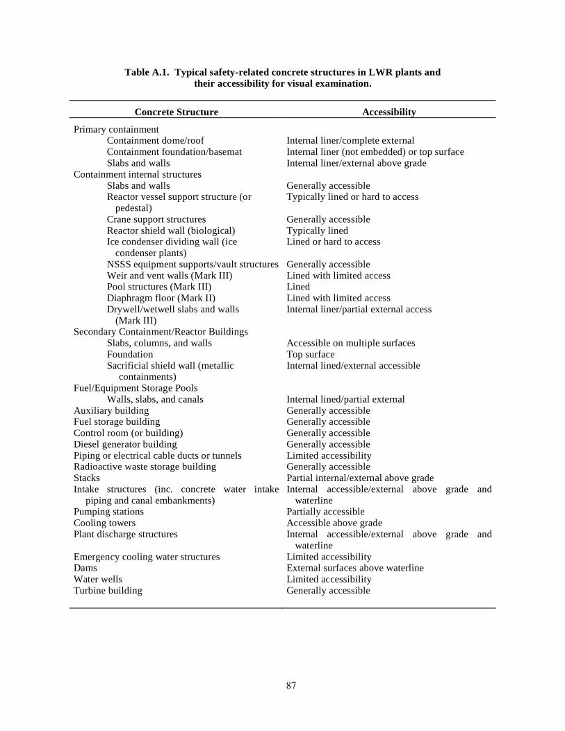
87
Table A.1. Typical safety-related concrete structures in LWR plants and their accessibility for visual examination.
Concrete Structure Accessibility
Primary containment Containment dome/roof Containment foundation/basemat Slabs and walls
Internal liner/complete external Internal liner (not embedded) or top surface Internal liner/external above grade
Containment internal structures Slabs and walls Reactor vessel support structure (or
pedestal) Crane support structures Reactor shield wall (biological) Ice condenser dividing wall (ice
condenser plants) NSSS equipment supports/vault structures Weir and vent walls (Mark III) Pool structures (Mark III) Diaphragm floor (Mark II) Drywell/wetwell slabs and walls (Mark III)
Generally accessible Typically lined or hard to access Generally accessible Typically lined Lined or hard to access Generally accessible Lined with limited access Lined Lined with limited access Internal liner/partial external access
Secondary Containment/Reactor Buildings Slabs, columns, and walls Foundation Sacrificial shield wall (metallic
containments)
Accessible on multiple surfaces Top surface Internal lined/external accessible
Fuel/Equipment Storage Pools Walls, slabs, and canals
Internal lined/partial external
Auxiliary building Generally accessible Fuel storage building Generally accessible Control room (or building) Generally accessible Diesel generator building Generally accessible Piping or electrical cable ducts or tunnels Limited accessibility Radioactive waste storage building Generally accessible Stacks Partial internal/external above grade Intake structures (inc. concrete water intake
piping and canal embankments) Internal accessible/external above grade and
waterline Pumping stations Partially accessible Cooling towers Accessible above grade Plant discharge structures Internal accessible/external above grade and
waterline Emergency cooling water structures Limited accessibility Dams External surfaces above waterline Water wells Limited accessibility Turbine building Generally accessible
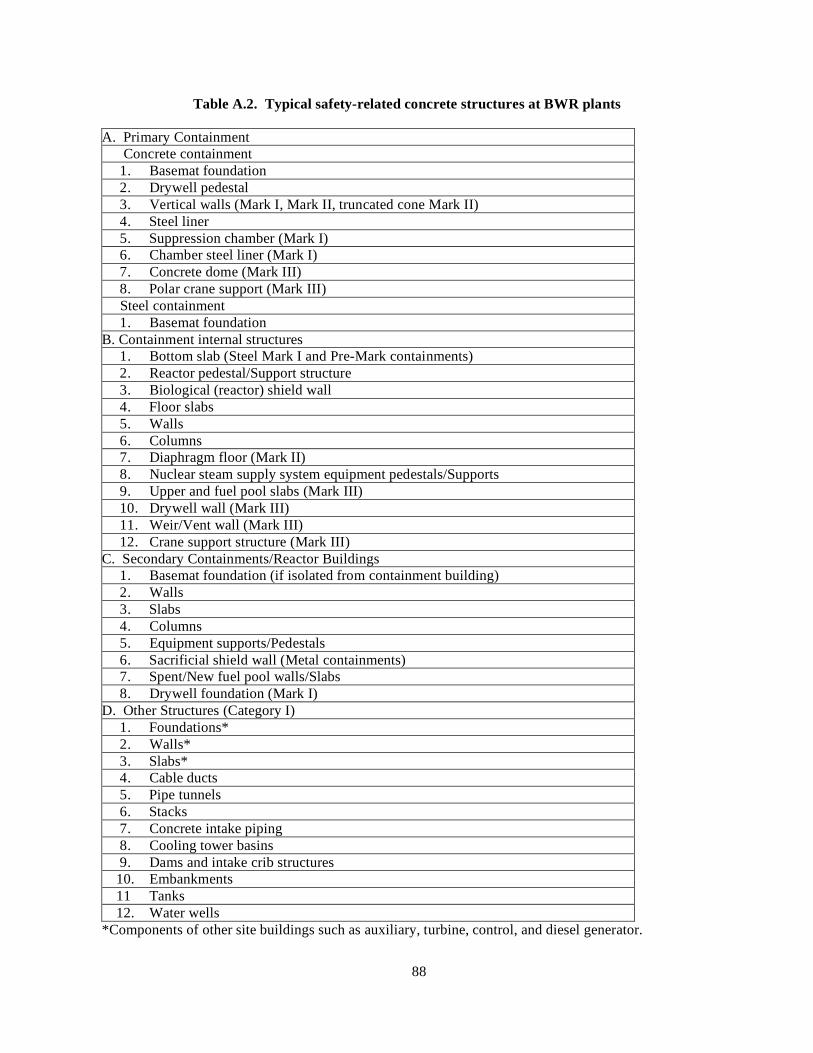
88
Table A.2. Typical safety-related concrete structures at BWR plants
A. Primary Containment Concrete containment 1. Basemat foundation 2. Drywell pedestal 3. Vertical walls (Mark I, Mark II, truncated cone Mark II) 4. Steel liner 5. Suppression chamber (Mark I) 6. Chamber steel liner (Mark I) 7. Concrete dome (Mark III) 8. Polar crane support (Mark III) Steel containment 1. Basemat foundation B. Containment internal structures 1. Bottom slab (Steel Mark I and Pre-Mark containments) 2. Reactor pedestal/Support structure 3. Biological (reactor) shield wall 4. Floor slabs 5. Walls 6. Columns 7. Diaphragm floor (Mark II) 8. Nuclear steam supply system equipment pedestals/Supports 9. Upper and fuel pool slabs (Mark III) 10. Drywell wall (Mark III) 11. Weir/Vent wall (Mark III) 12. Crane support structure (Mark III) C. Secondary Containments/Reactor Buildings 1. Basemat foundation (if isolated from containment building) 2. Walls 3. Slabs 4. Columns 5. Equipment supports/Pedestals 6. Sacrificial shield wall (Metal containments) 7. Spent/New fuel pool walls/Slabs 8. Drywell foundation (Mark I) D. Other Structures (Category I) 1. Foundations* 2. Walls* 3. Slabs* 4. Cable ducts 5. Pipe tunnels 6. Stacks 7. Concrete intake piping 8. Cooling tower basins 9. Dams and intake crib structures 10. Embankments 11 Tanks 12. Water wells *Components of other site buildings such as auxiliary, turbine, control, and diesel generator.

89
Table A.3. Typical safety-related concrete structures at PWR plants
A. Primary Containment Concrete containment 1. Basemat foundation 2. Tendon access galleries 3. Vertical walls (and buttresses) 4. Ring girder (Prestressed concrete containment vessel) Steel containment 1. Basemat foundation B. Containment internal structures 1. Bottom floor (Metal containments) 2. Floor slabs 3. Walls 4. Columns 5. Nuclear steam supply system equipment pedestals/Supports 6. Primary shield wall (Reactor cavity) 7. Reactor coolant vault walls 8. Beams 9. Crane support structures 10. Ice condenser divider wall and slab 11. Refueling pool and canal walls C. Secondary Containment Building (Metal containments) 1. Foundation 2. Walls 3. Slabs D. Other Structures (Category I) 1. Foundations* 2. Walls* 3. Slabs* 4. Cable ducts 5. Pipe tunnels 6. Stacks 7. Concrete intake piping 8. Hyperbolic cooling towers 9. Dams 10. Intake crib structures 11. Embankments 12. Tanks 13. Water wells *Components of other site buildings such as auxiliary, turbine, control, and diesel generator.

90
Figure A.1 BWR Mark I type reinforced concrete containment.
Source: BWR Containment Structures License Renewal Industry Report: Revision 1, EPRI TR-
103840, Electric Power Research Institute, Palo Alto, California, July 1994. Permission to use this copyrighted material is granted by the Electric Power Research Institute.
Figure A.2. BWR Mark II type reinforced concrete containment.
Source: BWR Containment Structures License Renewal Industry Report: Revision 1, EPRI TR-
103840, Electric Power Research Institute, Palo Alto, California, July 1994. Permission to use this copyrighted material is granted by the Electric Power Research Institute.

91
Figure A.3. BWR Mark III type reinforced concrete containment.
Source: BWR Containment Structures License Renewal Industry Report: Revision 1, EPRI TR-
103840, Electric Power Research Institute, Palo Alto, California, July 1994. Permission to use this copyrighted material is granted by the Electric Power Research Institute.
Figure A.4. PWR subatmospheric type reinforced concrete containment.
Source: D. J. Naus, C. B. Oland, and B. R. Ellingwood, Report on Aging of Nuclear Power Plant
Reinforced Concrete Structures, NUREG/CR-6424, U.S. Nuclear Regulatory Commission, Washington, DC, March 1996.

92
Figure A.5. PWR reinforced concrete containment with ice condenser.
Source: D. J. Naus, C. B. Oland, and B. R. Ellingwood, Report on Aging of Nuclear Power Plant
Reinforced Concrete Structures, NUREG/CR-6424, U.S. Nuclear Regulatory Commission, Washington, DC, March 1996.
Figure A.6. PWR large dry prestressed concrete containment.
Source: D. J. Naus, C. B. Oland, and B. R. Ellingwood, Report on Aging of Nuclear Power Plant
Reinforced Concrete Structures, NUREG/CR-6424, U.S. Nuclear Regulatory Commission, Washington, DC, March 1996.
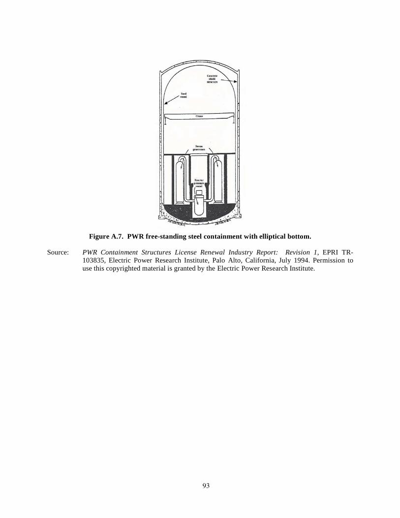
93
Figure A.7. PWR free-standing steel containment with elliptical bottom.
Source: PWR Containment Structures License Renewal Industry Report: Revision 1, EPRI TR-
103835, Electric Power Research Institute, Palo Alto, California, July 1994. Permission to use this copyrighted material is granted by the Electric Power Research Institute.

94

95
APPENDIX B: NUCLEAR POWER PLANT CONCRETE STRUCTURES OPERATING EXPERIENCE
B.1 Discussion In general, the performance of nuclear power plant safety-related concrete structures has been very good. However, there have been several isolated incidences that if not remedied could challenge the capacity of the containment and other safety-related structures to meet future functional and performance requirements. Table B.1 presents a summary of local degradation mechanisms that have been observed by one organization during condition surveys of various concrete structures at both U.S. and foreign nuclear power plants located in areas having several different climatic conditions.B.1 Some general observations derived from these results were that virtually all nuclear power plants have experienced cracking of the concrete structures that exceeds typical acceptance criteria for width and length, numerous nuclear power plants had ground water intrusion occurring through the power block or other subsurface structures, and aging concerns exist for subsurface concrete structures as their physical condition cannot easily be verified. Collectively, it was concluded in this study that the general performance of the nuclear power plant concrete structures has been quite favorable, and proper evaluation and treatment of observed degradation at an early stage is both a cost effective and necessary approach to long-term plant operations. More specific results on the performance of U.S. concrete structures is provided below. Most of the instances related to degradation of nuclear power plant concrete structures in the U.S. occurred early in their life and have been corrected.B.2,B.3 Causes were primarily related either to improper material selection and construction/design deficiencies, or environmental effects. Examples of some of the problems attributed to these deficiencies include low 28-d concrete compressive strengths, voids under the post-tensioning tendon bearing plates resulting from improper concrete placement; cracking of post-tensioning tendon anchor heads due to stress corrosion or embrittlement; and containment dome delaminations due to low quality aggregate materials and absence of radial steel reinforcement or unbalanced prestressing forces.B.4-B.6 Other construction-related problems have included occurrence of excessive voids or honeycomb in the concrete, contaminated concrete, cold joints, cadweld (steel reinforcement connector) deficiencies, materials out of specification, higher than code-allowable concrete temperatures, misplaced steel reinforcement, post-tensioning system button-head deficiencies, and water-contaminated corrosion inhibitors.B.2 Although continuing the service of a nuclear power plant past the initial operating license period is not expected to be limited by the concrete structures, several incidences of age-related degradation have been reported.B.4-B.9 Examples of some of these problems include corrosion of steel reinforcement in water intake structures, corrosion of post-tensioning tendon wires, leaching of tendon gallery concrete, low prestressing forces, and leakage of corrosion inhibitors from tendon sheaths. Other related problems include cracking and spalling of containment dome concrete due to freeze-thaw damage, low strengths of tendon wires, contamination of corrosion inhibitors by chlorides, and corrosion of concrete containment liners. Table B.2 provides a sampling of documented concrete problem areas in nuclear power plants in the U.S. As the plants age the incidences of degradation are expected to increase, primarily due to environmental effects. Additional information on the durability of U.S. nuclear power plant reinforced concrete structures is available.B.2,B.2-B.9 Documented information on problem areas experienced with nuclear power plant concrete structures in other countries is also available. B.10
96
B.2 References B.1 F. E. Gregor and C. J. Hookham, "Remant Life Preservation of LWR Plant Structures," pp. 453–
459 in Transactions of the 12th International Conference on Structural Mechanics in Reactor Technology held August 15–20, 1993, in Stuttgart, Germany, Paper DH06/2, Elsevier Science Publishers, Amsterdam, The Netherlands, 1993.
B.2 D. J. Naus, Concrete Component Aging and Its Significance Relative to Life Extension of Nuclear Power Plants, NUREG/CR-4652 (ORNL/TM-10059), Martin Marietta Energy Systems, Inc., Oak Ridge National Laboratory, Oak Ridge, Tennessee, September 1986.
B.3 P. D. Krauss, Repair Materials and Techniques for Concrete Structures in Nuclear Power Plants, ORNL/NRC/LTR-93/28, Martin Marietta Energy Systems, Inc., Oak Ridge National Laboratory, Oak Ridge, Tennessee, Mary 1994.
B.4 H. Ashar, D. J. Naus, and C. P. Tan, "Prestressed Concrete in U.S. Nuclear Power Plants (Part 1)," pp. 30–34 in Concrete International 16(5), American Concrete Institute, Farmington Hills, Michigan, May 1994.
B.5 H. Ashar, C. P. Tan, and D. J. Naus, "Prestressed Concrete in U.S. Nuclear Power Plants (Part 2)," pp. 58–61 in Concrete International 16(6), American Concrete Institute, Farmington Hills, Michigan, June 1994.
B.6 H. Ashar and D. Jeng, "Effectiveness of In-Service Inspection Requirements of Prestressed Concrete Containments — U.S. Experience," Proceedings of Second International Conference on Containment Design and Operation, Toronto, Ontario, Canada, October 1990.
B.7 H. Ashar and G. Bagchi, Assessment of Inservice Conditions of Safety-Related Nuclear Plant Structures, NUREG-1522, U.S. Nuclear Regulatory Commission, Washington, D.C., July 1995.
B.8 J. I. Braverman, C. H. Hofmayer, R. J. Morante, S. Shteyngart, and P. Bezler, “Assessment of Age-Related Degradation of Structures and Passive Components for U.S. Nuclear Power Plants,” NUREG/CR-6679, U. S. Nuclear Regulatory Commission, Washington, D.C., August 2000.
B.9 Degradation of Prestressing Tendon Systems in Prestressed Concrete Containments, NRC Information Notice 99-10, Rev. 1, U. S. Nuclear Regulatory Commission, Washington, D.C., October 7, 1999.
B.10 Assessment and Management of Major Nuclear Power Plant Components Important to Safety: Concrete Containment Buildings, IAEA-TECDOC-1025, International Atomic Energy Agency, Vienna, Austria, June 1998.

97
Table B.1 Condition survey results for various NPP concrete structures
Local Plant Degradation Mechanisms A B C D E F G H I J
Concrete Chemical Attack b,c c b c c c c c Efflorescence and Leaching
b,c,d b,c b,d b,d d b,d,f a,b, c,d
b,f
Alkali-Aggregate Reaction
a
Freeze/Thaw Cycling
d a,d d f
Thermal Exposure c c c c Abrasion/Erosion c c,d Fatigue/Vibration c Cracking c,d,
f,g a,b, c,d
c,d,g c,d a,b, c,d,g
b,e, d,f,g
b,f b,c, d,f
b,c, d,f
b,f,g
Conventional Reinforcing
Corrosion b,d b,d b b,d b b,d b b,f
Prestressing System
Corrosion n/a e1 n/a n/a n/a n/a n/a n/a n/a n/a
Block Walls
Excessive Cracking c d c a
Structural Steel and Liners
Corrosion d e c,d c,e e g
Soil/Structure Issues
Differential Settlement
c
Soil Erosion (Scour) d Key:
a – External Structure (Power Block) e – Containment Vessel b – Subgrade Structure (Power Block) f – Other Site Structure c – Internal Structure (Power Block) g – Equipment Supports d – Water Control Structure (Intake, Discharge, Etc.) Notes: Notes: 1. Corrosion limited to exposed grease can and bearing plate surfaces (no tendon corrosion noted).
Source: F. E. Gregor and C. J. Hookham, “Remnant Life Preservation of LWR Plant Structures,” Transactions of the 12th International Conference on Structural Mechanics in Reactor Technology held August 15–20, 1993, in Stuttgart, Germany, Elsevier Science Publishers, Amsterdam, The Netherlands, 1993. Permission to use this copyrighted material is granted by the authors.
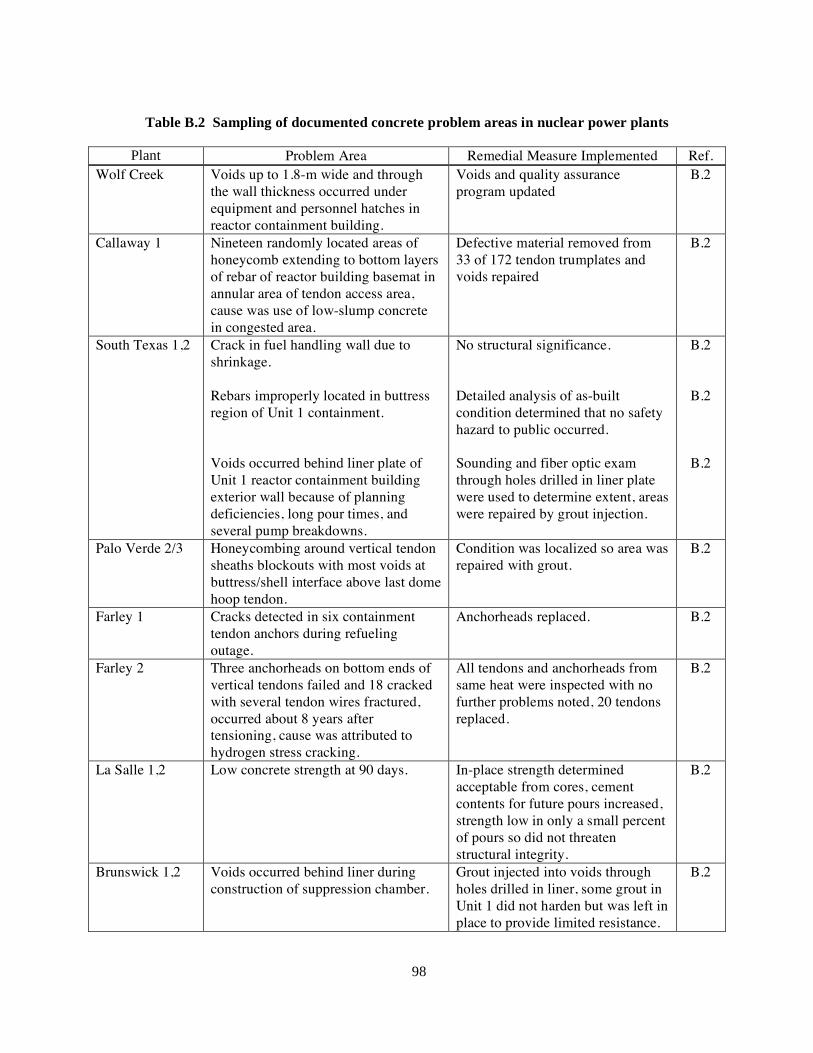
98
Table B.2 Sampling of documented concrete problem areas in nuclear power plants
Plant Problem Area Remedial Measure Implemented Ref.
Wolf Creek Voids up to 1.8-m wide and through the wall thickness occurred under equipment and personnel hatches in reactor containment building.
Voids and quality assurance program updated
B.2
Callaway 1 Nineteen randomly located areas of honeycomb extending to bottom layers of rebar of reactor building basemat in annular area of tendon access area, cause was use of low-slump concrete in congested area.
Defective material removed from 33 of 172 tendon trumplates and voids repaired
B.2
South Texas 1,2 Crack in fuel handling wall due to shrinkage. Rebars improperly located in buttress region of Unit 1 containment. Voids occurred behind liner plate of Unit 1 reactor containment building exterior wall because of planning deficiencies, long pour times, and several pump breakdowns.
No structural significance. Detailed analysis of as-built condition determined that no safety hazard to public occurred. Sounding and fiber optic exam through holes drilled in liner plate were used to determine extent, areas were repaired by grout injection.
B.2
B.2
B.2
Palo Verde 2/3 Honeycombing around vertical tendon sheaths blockouts with most voids at buttress/shell interface above last dome hoop tendon.
Condition was localized so area was repaired with grout.
B.2
Farley 1 Cracks detected in six containment tendon anchors during refueling outage.
Anchorheads replaced. B.2
Farley 2 Three anchorheads on bottom ends of vertical tendons failed and 18 cracked with several tendon wires fractured, occurred about 8 years after tensioning, cause was attributed to hydrogen stress cracking.
All tendons and anchorheads from same heat were inspected with no further problems noted, 20 tendons replaced.
B.2
La Salle 1,2 Low concrete strength at 90 days. In-place strength determined acceptable from cores, cement contents for future pours increased, strength low in only a small percent of pours so did not threaten structural integrity.
B.2
Brunswick 1,2 Voids occurred behind liner during construction of suppression chamber.
Grout injected into voids through holes drilled in liner, some grout in Unit 1 did not harden but was left in place to provide limited resistance.
B.2

99
Table B.2 (cont.) Sampling of documented concrete problem areas in nuclear power plants
Plant Problem Area Remedial Measure Implemented Ref. Summer 1 Voids located behind liner plate of
reactor containment building wall, windows cut in liner revealed voids up to 22-cm deep, cause was use of low-slump concrete with insufficient compaction. Excessive heat from welding caused liner attached to concrete on inside face of concrete primary shield wall cavity to buckle and fail stud anchors.
Voids chipped, cleaned to sound concrete, and filled with nonshrink grout, liner repaired and all welds leak tested. Liner and concrete to depth of 15 cm removed, new liner plate welded in place and void filled with high-strength grout.
B.2
B.2
Sequoyah 2 Concrete in outer 2.5 to 5 cm of Unit 2 shield building was under strength because of exposure to freezing temperatures at early concrete age
Determined not to affect shield building capability.
B.2
Beaver Valley 1 Void ~0.9-m long and 0.9-m deep in outer containment wall in concrete ring around equipment hatch.
No threat to structural integrity, void repaired with dry pack.
B.2
North Anna Cracks >1.6-mm wide in containment floor slab occurred around neutron shield tank anchor bolts following pressure testing of seal chambers due to inadvertent pressurization, cores showed cracks extended into concrete vertically. Cracked basemat
Cracks no structural threat, routed and sealed to prevent fluid penetration.
B.2
B.7 San Onofre 3 Tendon liftoff forces in excess of
maximum value listed in plant technical specifications, cause was lower relaxation rate than expected.
No threat to structural integrity. B.2
Zion 1 Excessive pitting in some tendon wires in Unit 2 during installation, cause was outdoor storage in conjunction with high precipitation and inadequate protection.
Defective tendons replaced. B.2
Crystal River 3 28-day concrete strength was low due to failure of cement to meet specifications. Dome delaminated over ~32-m diameter area due to low concrete properties and no radial reinforcement to accommodate radial tension due to post-tensioning.
Design review revealed strength attained to be adequate, cement inspection increased. Upper delaminated section removed, additional rebars provided, concrete replaced, dome retensioned, and structural integrity test conducted.
B.2
B.2
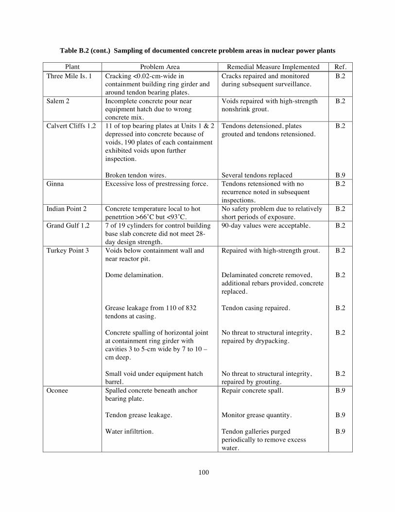
100
Table B.2 (cont.) Sampling of documented concrete problem areas in nuclear power plants
Plant Problem Area Remedial Measure Implemented Ref. Three Mile Is. 1 Cracking <0.02-cm-wide in
containment building ring girder and around tendon bearing plates.
Cracks repaired and monitored during subsequent surveillance.
B.2
Salem 2 Incomplete concrete pour near equipment hatch due to wrong concrete mix.
Voids repaired with high-strength nonshrink grout.
B.2
Calvert Cliffs 1,2 11 of top bearing plates at Units 1 & 2 depressed into concrete because of voids, 190 plates of each containment exhibited voids upon further inspection. Broken tendon wires.
Tendons detensioned, plates grouted and tendons retensioned. Several tendons replaced
B.2
B.9 Ginna Excessive loss of prestressing force. Tendons retensioned with no
recurrence noted in subsequent inspections.
B.2
Indian Point 2 Concrete temperature local to hot penetrtion >66˚C but <93˚C.
No safety problem due to relatively short periods of exposure.
B.2
Grand Gulf 1,2 7 of 19 cylinders for control building base slab concrete did not meet 28-day design strength.
90-day values were acceptable. B.2
Turkey Point 3 Voids below containment wall and near reactor pit. Dome delamination. Grease leakage from 110 of 832 tendons at casing. Concrete spalling of horizontal joint at containment ring girder with cavities 3 to 5-cm wide by 7 to 10 –cm deep. Small void under equipment hatch barrel.
Repaired with high-strength grout. Delaminated concrete removed, additional rebars provided, concrete replaced. Tendon casing repaired. No threat to structural integrity, repaired by drypacking. No threat to structural integrity, repaired by grouting.
B.2
B.2
B.2
B.2
B.2
Oconee Spalled concrete beneath anchor bearing plate. Tendon grease leakage. Water infiltrtion.
Repair concrete spall. Monitor grease quantity. Tendon galleries purged periodically to remove excess water.
B.9
B.9
B.9

101
Table B.2 (cont.) Sampling of documented concrete problem areas in nuclear power plants
Plant Problem Area Remedial Measure Implemented Ref. Millstone 3 Cement erosion of porous concrete
subfoundation. Surveillance of sumps for cement erosion, settlement monitoring.
Brunswick 1,2 Corrosion of drywell liner at junction of base floor and liner.
Cleaned joints, repaired pitted liner plate, resealed gap.
B.7
Waterford Cracked basemat. N.A.* B.7 Diablo Canyon Rebar corrosion and concrete cracking N.A. B.7 San Onofre 1 Exterior concrete walls of intake
structure and concrete beams supporting service water pumps were cracked extensively.
N.A. B.7
Pilgrim Rebar corrosion and concrete cracking. N.A. B.7 Trojan Concrete cracking and leaching in
bioshield wall, auxiliary building, control building, fuel building, and service water pump room.
N.A. B.7
Point Beach General concrete cracking in pumphouse walls, auxiliary building, and emergency diesel generator building. Ground water seepage in undrground portions of safety-related structures.
N.A. B.7
B.7
Robinson 2 Cracking and spalling of concrete (in limited areas) in walls and ceilings of the reactor auxiliary building, emergency diesel generator room, and intake structure. Liner corrosion
N.A. B.7
B.8 Beaver Valley 1 Cracks, water infiltration, and calcium
deposits in the ceilings and walls of the service building, safeguard structure, and steam generator drain tank. Liner corrosion.
N.A. B.7
B.8 Cooper Cracking and spalling of concrete in
service water booster pump room and in exterior walls of the diesel generator building and reactor building
N.A. B.7
Fort Saint Vrain Tendon wire failures due to corrosion caused by microbiological attack of corrosion inhibitor.
Analysis revealed sufficient tendons intact to provide structural integrity, surveillance increased and tendons inerted by nitrogen blanket.
B.2
* N.A.

102

103
APPENDIX C: COMMENTARY ON CRACKING AND CORROSION The relation between crack characteristics and corrosion needs to be addressed from two aspects. The first relates to the crack characteristics and corrosion occurrence; the second addresses the relation between corrosion significance and crack characteristics (e.g., visual features or indicators). C.1 Crack Characteristics and Corrosion
Crack characteristics identified to be of importance to corrosion include width, orientation or type, propagation status, frequency, and shape.
Two viewpoints, or theories, have been proposed relative to the significance of crack width (or presence of a crack) and corrosion.C.1 Theory one believes that cracks significantly reduce the service life of structures by permitting access of carbon dioxide, chlorides, water, and oxygen to the reinforcing steel. The cracks thus accelerate corrosion initiation and provide space for the deposition of the corrosion products. Several researchers studying the effects of cracks transverse to steel reinforcement seem to confirm that this theory is correct and found a relation between crack width, exposure condition, and corrosion.C.2 Information in support of this is provided in Figure C.1 which presents data relating surface crack width, carbonation, and corrosion of reinforcement.C.3 In this figure the triangular points represent steel reinforcement at pour joints and the circular points represent steel reinforcement not located at pour joints. Theory one is embodied in many national codes in which crack widths at the concrete surface are limited based on exposure conditions.C.4,C.5 A comparison of code requirements for crack control in reinforced concrete structures is available.C.6
Figure C.1 Surface crack width, carbonation depth, and corrosion.
Source: A. Ida and T. Yokomuro, “Durability Survey of 60 Year Old Reinforced Concrete Office Building, Annual Meeting, Architectural Institute of Japan, Tokyo, 1987.
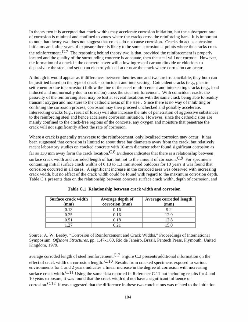
104
In theory two it is accepted that crack widths may accelerate corrosion initiation, but the subsequent rate of corrosion is minimal and confined to zones where the cracks cross the reinforcing bars. It is important to note that theory two does not suggest that cracks do not cause corrosion. Cracks do act as corrosion initiators and, after years of exposure there is likely to be some corrosion at points where the cracks cross the reinforcement.C.7 The reasoning behind theory two is that, provided the reinforcement is properly located and the quality of the surrounding concrete is adequate, then the steel will not corrode. However, the formation of a crack in the concrete cover will allow ingress of carbon dioxide or chlorides to depassivate the steel and set up an electrolytic cell at or near the crack where corrosion can occur. Although it would appear as if differences between theories one and two are irreconcilable, they both can be justified based on the type of crack – coincident and intersecting. Coincident cracks (e.g., plastic settlement or due to corrosion) follow the line of the steel reinforcement and intersecting cracks (e.g., load induced and not normally due to corrosion) cross the steel reinforcement. With coincident cracks the passivity of the reinforcing steel may be lost at several locations with the same crack being able to readily transmit oxygen and moisture to the cathodic areas of the steel. Since there is no way of inhibiting or confining the corrosion process, corrosion may then proceed unchecked and possibly accelerate. Intersecting cracks (e.g., result of loads) will also increase the rate of penetration of aggressive substances to the reinforcing steel and hence accelerate corrosion initiation. However, since the cathodic sites are mainly confined to the crack-free regions of the concrete, any oxygen and moisture that penetrate the crack will not significantly affect the rate of corrosion. Where a crack is generally transverse to the reinforcement, only localized corrosion may occur. It has been suggested that corrosion is limited to about three bar diameters away from the crack, but relatively recent laboratory studies on cracked concrete with 10-mm diameter rebar found significant corrosion as far as 130 mm away form the crack location.C.8 Evidence indicates that there is a relationship between surface crack width and corroded length of bar, but not to the amount of corrosion.C.9 For specimens containing initial surface crack widths of 0.13 to 1.3 mm stored outdoors for 10 years it was found that corrosion occurred in all cases. A significant increase in the corroded area was observed with increasing crack width, but no effect of the crack width could be found with regard to the maximum corrosion depth. Table C.1 presents data on the relationship between concrete surface crack width, depth of corrosion, and
Table C.1 Relationship between crack width and corrosion
Surface crack width (mm)
Average depth of corrosion (mm)
Average corroded length (mm)
0.13 0.16 9.2 0.25 0.16 12.9 0.51 0.18 12.8 1.27 0.21 15.0
Source: A. W. Beeby, “Corrosion of Reinforcement and Crack Widths,” Proceedings of International Symposium, Offshore Structures, pp. 1.47-1.60, Rio de Janeiro, Brazil, Pentech Press, Plymouth, United Kingdom, 1979. average corroded length of steel reinforcement.C.7 Figure C.2 presents additional information on the effect of crack width on corrosion length. C.10 Results from cracked specimens exposed to various environments for 1 and 2 years indicates a linear increase in the degree of corrosion with increasing surface crack width.C.11 Using the same data reported in Reference C.11 but including results for 4 and 10 years exposure, it was found that the crack width did not have a significant influence on corrosion.C.12 It was suggested that the difference in these two conclusions was related to the initiation
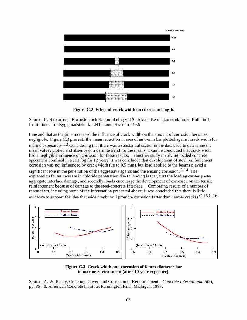
105
Figure C.2 Effect of crack width on corrosion length.
Source: U. Halvorsen, “Korrosion och Kalkurlakning vid Sprickor I Betongkonstruktioner, Bulletin 1, Institutionen for Bygggnadsteknik, LHT, Lund, Sweden, 1966 time and that as the time increased the influence of crack width on the amount of corrosion becomes negligible. Figure C.3 presents the mean reduction in area of an 8-mm bar plotted against crack width for marine exposure.C.13 Considering that there was a substantial scatter in the data used to determine the mean values plotted and absence of a definite trend for the means, it can be concluded that crack width had a negligible influence on corrosion for these results. In another study involving loaded concrete specimens confined in a salt fog for 12 years, it was concluded that development of steel reinforcement corrosion was not influenced by crack width (up to 0.5 mm), but load applied to the beams played a significant role in the penetration of the aggressive agents and the ensuing corrosion.C.14 The explanation for an increase in chloride penetration due to loading is that, first the loading causes paste-aggregate interface damage, and secondly, loads encourage the development of corrosion on the tensile reinforcement because of damage to the steel-concrete interface. Comparing results of a number of researchers, including some of the information presented above, it was concluded that there is little evidence to support the idea that wide cracks will promote corrosion faster than narrow cracks).C.15,C.16
Figure C.3 Crack width and corrosion of 8-mm-diameter bar in marine environment (after 10-year exposure).
Source: A. W. Beeby, Cracking, Cover, and Corrosion of Reinforcement,” Concrete International 5(2), pp. 35-40, American Concrete Institute, Farmington Hills, Michigan, 1983.

106
The reason proposed for this is that in order for corrosion to proceed, oxygen must be supplied to the cathodic regions of the reinforcement and there must be an electrical path between the anode and the cathode. Since both of these factors are independent of crack width, it was concluded that the corrosion rate is also independent of crack width. Information presented above seems to indicate that larger crack widths increase the probability of corrosion,C.17 however values of crack width are not always reliable indicators of corrosion and deterioration expected.C.18 Other investigators have produced similar evidence to support the general conclusion that corrosion does not exhibit a relationship to crack width.C.19-C.21 Thus, except for larger crack widths that are likely to cause a breakdown of the passivity of the reinforcement and hence cause corrosion to start earlier, there is no reason to expect the rate of corrosion to be influenced by cracks.C.12,C.16 Unfortunately, at present there are no alternatives to describing cracks other than by crack width at the surface. Therefore, until recently, most code provisions address durability by limiting crack width at the concrete surface. In addition to the cause of a crack, the time-dependent behavior of the crack must be determined in order to judge the significance of a crack.C.22 Dormant cracks have widths that do not vary with time and as a result may be blocked by the deposition of extraneous substances. Dormant cracks also may self-heal through filling with stationary or slowly moving water leading to cement hydration products and Ca(OH)2 crystals being precipitated in the crack.C.23 Active cracks on the other hand have widths that vary with time and are more likely to provide access to the steel reinforcement. As the frequency or number of cracks increases, the number of sites at which steel reinforcement corrosion can occur increases so there is an increasing risk that a crack will have a significant amount of corrosion. Exposure tests on cracked reinforced concrete beams showed that for any given crack width, the depth of corrosion was generally fairly small (Figure C.4).C.16 Detailed analysis of this data (presented in Figure C.5) indicate that the distributions of the corrosion depths vary exponentially, perhaps suggesting that the higher the frequency of cracking the greater the risk of a particular amount of corrosion. Conversely, for a given environment, if a structure has only a few cracks, the risk of obtaining a crack with a high degree of corrosion is low because of the distribution.
Figure C.4 Corrosion depth versus crack width after 10-year exposure.
Source: A. W. Beeby, “Cracking and Corrosion,” Concrete In the Oceans, Technical Report No. 1, Cement and Concrete Association, Slough, United Kingdom, 1978.

107
Figure C.5 Distribution of corrosion depths in Figure C.4.
Source: A. W. Beeby, “Cracking and Corrosion,” Concrete In the Oceans, Technical Report No. 1, Cement and Concrete Association, Slough, United Kingdom, 1978. As noted previously, most codes have dealt with crack width at the surface of the structure. It may be demonstrated that some cracks may: (a) taper quickly from the surface (e.g., plastic shrinkage cracks), (b) remain approximately parallel throughout the section (e.g., thermal contraction cracks in thin walls), and (c) widen within the section (e.g., thermal gradient cracks within deep foundations).C.23 However, crack width at the surface may not be a good indicator of crack width at the reinforcement as shown in Figure C.6. Thus a wide surface crack may not imply a wide internal crack. The crack width at the steel reinforcement is a function of several factors (including the crack origin): amount of concrete cover, steel stress, reinforcement ratio, reinforcement arrangement, diameter of the reinforcement bars, and depth of tensile zone.C.24 C.2 Corrosion Significance and Crack Characteristics
The other important aspect of the relationship between concrete cracking and corrosion significance relates to the extent of concrete cracking that occurs as a result of corrosion of the embedded steel reinforcement. In other words – What is the relation between characteristics (e.g., width) of cracks formed at the concrete surface resulting from corrosion and the extent of corrosion (e.g., loss of steel reinforcement section or loss of bond between the steel reinforcement and concrete)? Occurrence of

108
Figure C.6 Variation of crack width with depth. Source: Concrete Society, “Non-Structural Cracks in Concrete,” Technical Report No. 22, London, United Kingdom. 1992. concrete cover cracking due to corrosion of the steel reinforcement is important not only because it affects the functional and structural properties of reinforced concrete but, after cracking of the cover concrete, the rate of corrosion increases significantly.C.25 Although structural properties are not damaged significantly at the time of initial cover concrete cracking, spalling of cover concrete will follow shortly thereafter. It has been noted in studies involving deterioration of bridge decks that the cracking period, or time between corrosion initiation and concrete cracking, ranges between two and five years.C.26 Concrete cover depth, reinforcing steel spacing and size, and concrete strength were found to have little influence on the length of the cracking period. The most significant parameter with respect to the length of the cracking period was the corrosion rate. In the corrosion process, higher bursting forces causing cracking of concrete are signified by an increasing bar diameter, whereas the thickness and quality of concrete cover over the reinforcement characterize the resistance to the splitting-corrosion forces.∗ Cover to bar diameter (C/d) therefore is a significant corrosion protection parameter.C.30 For steel in concrete the passive corrosion rate is typically on the order of 1 µm/yr, but without the passive film the rate would be at least three orders of magnitude higher.C.31 Once the chloride ions reach the bar, cracks appear relatively soon in high quality concrete with low C/d values. In low quality concrete with high C/d values, it has been reported that
∗ It has been reported that smooth bars are more likely to suffer corrosion damage than deformed bars.C.27 Other research reports that deformed bars corrode more than plain bars.C.28 This study also indicates that the orientation of the steel bars influences steel corrosion in concrete. Due to the formation of gaps below the bottom of the horizontal steel, significant macrocell and microcell corrosion takes place and the presence of stirrups increases the macrocell activity. Other researchC.29 has noted that for a given corrosion penetration, larger reinforcement diameters will provide improved performance (longer service life) because the relative reduction in cross section for the larger diameter bars will be less.
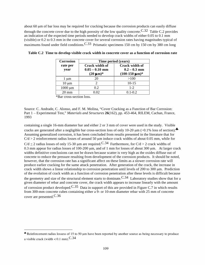
109
about 60 µm of bar loss may be required for cracking because the corrosion products can easily diffuse through the concrete cover due to the high porosity of the low quality concrete.C.32 Table C.2 provides an indication of the expected time periods needed to develop crack widths of either 0.05 to 0.1 mm (visible) or 0.2 to 0.3 mm in the concrete cover for several corrosion rates having magnitudes typical of maximums found under field conditions.C.33 Prismatic specimens 150 cm by 150 cm by 380 cm long
Table C.2 Time to develop visible crack width in concrete cover as a function of corrosion rate
Time period (years) Corrosion rate per
year Crack width of 0.05 – 0.10 mm
(20 µm)*
Crack width of 0.2 – 0.3 mm
(100-150 µm)* 1 µm 20 >100
10 µm 2 10-15 1000 µm 0.2 1-2 20 mm 0.02 0.1-0.2
*Bar cross-section loss. Source: C. Andrade, C. Alonso, and F. M. Molina, “Cover Cracking as a Function of Bar Corrosion: Part 1 – Experimental Test,” Materials and Structures 26(162), pp. 453-464, RILEM, Cachan, France, 1993 containing a single 16-mm diameter bar and either 2 or 3 mm of cover were used in the study. Visible cracks are generated after a negligible bar cross-section loss of only 10-20 µm (~0.1% loss of section).♣ Assuming generalized corrosion, it has been concluded from results presented in the literature that for C/d > 2 reinforcement radius losses of around 50 µm induce crack widths of about 0.05 mm, while for C/d < 2 radius losses of only 15-30 µm are required.C.34 Furthermore, for C/d > 2 crack widths of 0.3 mm appear for radius losses of 100-200 µm, and of 1 mm for losses of about 300 µm. At larger crack widths definitive conclusions can not be drawn because scatter is very high as the oxides diffuse out of concrete to reduce the pressure resulting from development of the corrosion products. It should be noted, however, that the corrosion rate has a significant affect on these limits as a slower corrosion rate will produce earlier cracking for the same attack penetration. After generation of the crack, the increase in crack width shows a linear relationship to corrosion penetration until levels of 200 to 300 µm. Prediction of the evolution of crack width as a function of corrosion penetration after these levels is difficult because the geometry and size of the structural element starts to dominate.C.34 Laboratory studies show that for a given diameter of rebar and concrete cover, the crack width appears to increase linearly with the amount of corrosion product developed.C.35 Data in support of this are provided in Figure C.7 in which results from 300-mm concrete cubes containing either a 9- or 10-mm diameter rebar with 25 mm of concrete cover are presented.C.36
♣ Reinforcement radius lossess of 15 to 50 µm have been reported by another source as being necessary to produce a visible crack (width < 0.1 mm).C.34

110
Figure C.7 Crack width versus amount corrosion.
Source: K. Maruyama, Shimomura, and H. Hamada, H. “Degradation Model for Reinforced Concrete Structures Under Salt Attack Environment, Private Communication, Nagaoka University of Technology, Japan, 1999. C.3 Summary In evaluating the condition of concrete structures, the relationship between crack characteristics and corrosion occurrence, and corrosion significance and crack characteristics needs to be addressed. Some general conclusions from the previous information are:
• Crack characteristics of importance to corrosion include width, orientation, or type; propagation status; frequency of occurrence; and shape;
• Although larger crack widths increase the probability of corrosion, values of crack width are not always reliable indicators of corrosion or deterioration expected;
• There appears to be a relationship between surface crack width and corroded length, but it is difficult to define a relationship between surface crack width and magnitude of corrosion;
• Cracks along reinforcement are of more importance than transverse cracks relative to accelerating corrosion;
• Active crack widths are more likely to accelerate the corrosion process than passive crack widths;
• Load can accelerate the corrosion process; • Visible cracks due to corrosion appear after reinforcing section losses of 10 - 50 µm;
• Ratio of cover to bar diameter is a significant corrosion parameter, with amount of corrosion required to produce cracking increasing as ratio increases;
• Experimental results indicate that performance of beams, columns, and walls exhibiting corrosion can improve up to point of concrete cracking; and
• Corrosion cracking can affect failure mode, with cracks that coincide with loading direction having the most effect .

111
C.4 References C.1 D. Darwin, “Debate: Crack Width, Cover and Corrosion,” Concrete International Design and
Construction 7(5), pp. 20-35, American Concrete Institute, Farmington Hills, Michigan, 1985. C.2 C. Arya and L. A. Wood, “The Relevance of Cracking in Concrete to Corrosion of
Reinforcement,” Technical Report No. 44, Concrete Society, Slough, Berkshire, United Kingdom, 1995.
C.3 A. Ida and T. Yokomuro, “Durability Survey of 60 Year Old Reinforced Concrete Office Building, Annual Meeting, Architectural Institute of Japan, Tokyo, 1987.
C.4 Building Code Requirements for Structural Concrete and Commentary, ACI Standard 318-05, American Concrete Institute, Farmington Hills, Michigan, November 2005.
C.5 Structural Use of Concrete – Code of Practice for Design and Construction, BS 8110, British Standards Institution, London, United Kingdom, 1985.
C.6 G. T. Halvorsen, “Requirements for Crack Control,” Lewis H. Tuthill International Symposium on Concrete and Concrete Construction, SP-124, pp. 275-322, American Concrete Institute, Farmington Hills, Michigan, 1987.
C.7 A. W. Beeby, “Corrosion of Reinforcement and Crack Widths,” Proceedings of International Symposium, Offshore Structures, pp. 1.47-1.60, Rio de Janeiro, Brazil, Pentech Press, Plymouth, United Kingdom, 1979.
C.8 P. D. Krauss, “Repair Materials and Techniques for Concrete Structures in Nuclear Power Plants,” ORNL/NRC/LTR-93/28, Martin Marietta Energy Systems, Inc., Oak Ridge National Laboratory, Oak Ridge, Tennessee, 1994.
C.9 B. Tremper, “The Corrosion of Reinforced Steel in Cracked Concrete,” Journal of the American Concrete Institute 18, Farmington Hills, Michigan, June 1947.
C.10 U. Halvorsen, “Korrosion och Kalkurlakning vid Sprickor I Betongkonstruktioner, Bulletin 1, Institutionen for Bygggnadsteknik, LHT, Lund, Sweden, 1966.
C.11 G. Rehm and H. Moll, “Versuche zum Studium des Einflusses der Rissbriete auf die Rostbilding an der Bewehrung von Stahlbeton-Bauteilen,” Heft 169, Deutscher Ausschuss fur Stahlbeton, Berlin, Germany, 1964.
C.12 P. Schiessl, “Admissible Crack Width In Reinforced Concrete Structures,” Inter-Association Colloquium on the Behaviour of In Service Concrete Structures, Contribution II 3-17, Preliminary Report Vol. 1, Liege, Belgium, 1975.
C.13 A. W. Beeby, Cracking, Cover, and Corrosion of Reinforcement,” Concrete International 5(2), pp. 35-40, American Concrete Institute, Farmington Hills, Michigan, 1983.
C.14 R. Francois and G. Arliguie, “Effect of Microcracks and Cracking on the Development of Corrosion in Reinforced Concrete Members,” Magazine of Concrete Research 51(2), pp. 143-150, London, United Kingdom, 1999.
C.15 A. W. Beeby, “Corrosion of Reinforcing Steel in Concrete and Its Relation to Cracking,” The Structural Engineer 56A(3), pp. 77-81, London, United Kingdom, March 1978.
C.16 A. W. Beeby, “Cracking and Corrosion,” Concrete In the Oceans, Technical Report No. 1, Cement and Concrete Association, Slough, United Kingdom, 1978.
C.17 A. W. Beeby, “The Prediction of Crack Width in Hardened Concrete,” The Structural Engineer 57A(1), pp. 9-17, London, United Kingdom, January 1979.
C.18 ACI Committee 224, “Causes, Evaluation, and Repair of Cracks in Concrete Structures,” Report No. 224R-84, Journal of the American Concrete Institute 81(3), pp. 211-230, American Concrete Institute, Farmington Hills, Michigan, 1984.
C.19 E. F. O’Neill, “Study of Reinforced Concrete Beams Exposed to Marine Environment,” Concrete in Marine Environment, SP-65, American Concrete Institute, Farmington Hills, Michiga, 1980.
C.20 M. Raphael and R. Shalon, “A Study of the Influence of Climate on Corrosion of Reinforcement, Proc. of RILEM International Symposium on Concrete and Reinforced Concrete in Hot Countries, pp. 77-96, Technion, Israel Institute of Technology, Haifa, 1971.

112
C.21 J. Houston, J. E. Atimtay, and P. M. Ferguson, “Corrosion of Reinforcing Steel Embedded in Structural Concrete,” Research Report No. 112-1-F, Center for Highway Research, University of Texas, Austin, 1972.
C.22 A. Nielsen, “How Wide is a Crack in Reinforced Concrete Allowed to be?” Miscellaneous Papers in Civil Engineering, Dialog 77, pp. 199-212, Danish Engineering Academy, Lyngby, 1978.
C.23 Non-Structural Cracks in Concrete, Technical Report No. 22, Concrete Society, London, United Kingdom. 1992.
C.24 D. G. Manning, “Debate: Crack Width, Cover, and Corrosion,” Concrete International Design and Construction 7(5), pp. 20-35, American Concrete Institute, Farmington Hills, Michigan, 1985.
C.25 S. Morinaga, “Prediction of Service Lives of Reinforced Concrete Buildings Based on the Corrosion Rate of Reinforcing Steel,” Durability of Building Materials and Components, E.&F. N Spon., London, United Kingdom, 1990.
C.26 P. D. Cady and R. E. Weyers, “Deterioration Rates of Concrete Bridge Decks,” Journal of Transportation Engineering 110(1), pp. 35-44, American Society of Civil Engineers, New York, New York, 1984.
C.27 H. Martin and P. Schiessl, “The Influence of Cracks on the Corrosion of Steel in Concrete,” Preliminary Report of RILEM International Symposium on the Durability of Concrete, Vol. II, Prague, Slovaki, 1969.
C.28 T. U. Mohammed, N. Otsuki, and M. Hisada, “Corrosion of Steel Bars with Respect to Orientation in Concrete,” ACI Materials Journal 96(2), pp. 154-159, American Concrete Institute, Farmington Hills, Michigan, 1999.
C.29 J. A. González, S. Feliu, P. Rodríguez, W. López, E. Ramírez, C. Alonso, and C. Andrade, “Some Questions on the Corrosion of Steel in Concrete – Part II: Corrosion Mechanism and Monitoring Service Life Prediction and Protection Methods,” Materials and Structures 29, pp. 97-104, RILEM, Cachan, France, March 1996.
C.30 G. J. Al-Sulaimani, M. Kaleemullah, I. A. Basunbul, and Rasheeduzzafar “Influence of Corrosion and Cracking on Bond Behavior and Strength of Reinforced Concrete Members,” ACI Structural Journal 87(2), pp. 220-231, American Concrete Institute, Farmington Hills, Michigan, 1990.
C.31 R. T. Foley, “Complex Ions and Corrosion,” Journal of the Electrochemical Society 122(11), pp. 1493-1549, 1975.
C.32 J. Rodriguez, M. Ortega, J. Casal, and J. M. Diez, “Corrosion of Reinforcement and Service Life of Concrete Structures,” 7th International Conference on the Durability of Building Materials and Components, Stockholm, Sweden, 1996.
C.33 C. Andrade, C. Alonso, and F. M. Molina, “Cover Cracking as a Function of Bar Corrosion: Part 1 – Experimental Test,” Materials and Structures 26(162), pp. 453-464, RILEM, Cachan, France, 1993.
C.34 C. Alonso, C. Andrade, J. Rodriguez, and J. M. Diez, “Factors Controlling Cracking of Concrete Affected by Reinforcement Corrosion,” Materials and Structures 31(211), pp. 435-441, RILEM, Cachan, France, 1998.
C.35 Japanese Concrete Institute, “Integrated Design of Concrete Structures,” JCI TC 961 Committee, Japan Concrete Institute, Tokyo, Japan, 1996.
C.36 K. Maruyama, Shimomura, and H. Hamada, H. “Degradation Model for Reinforced Concrete Structures Under Salt Attack Environment, Private Communication, Nagaoka University of Technology, Japan, 1999.

114