prestressedconcrete design (sab 4323) design for ultimate
TRANSCRIPT

Design for Ultimate Strength in
Prestressed Concrete Design
(SAB 4323)
1
Design for Ultimate Strength in
Shear
Dr. Roslli Noor Mohamed

Introduction
• The behaviour of prestressed concrete beams at failure
in shear is distinctly different from their behaviour in
flexure
• The beams fail abruptly without sufficient warning, and
the diagonal cracks that develop are considerably wider
2
the diagonal cracks that develop are considerably wider
than the flexural cracks
• Shear forces result in shear stress. Such a stress can
result in principal tensile stresses at the critical section
which can exceed the tensile strength of the concrete.
• When the tensile strength of the concrete is exceeded,
cracks will form

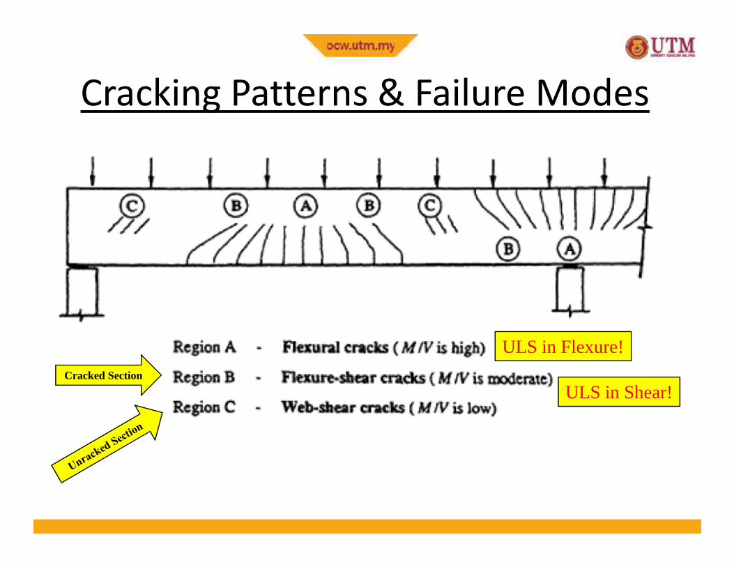
Cracking Patterns & Failure Modes
• Cracking in prestressed concrete beams at ultimate load depends on the local magnitudes of moment and shear as shown on the next two slides
• In regions where the moment is large and the shear is small, vertical flexural cracks appear after the normal tensile stress in the extreme concrete fibres exceeds the tensile strength of concrete. These are the cracks shown as type A
3
the extreme concrete fibres exceeds the tensile strength of concrete. These are the cracks shown as type A
• Where both the moment and shear force are relatively large, flexural cracks which are vertical at the extreme fibres become inclined as they extend deeper into the beam owing to the presence of shear stresses in the beam web. These inclined cracks, which are often quite flat in a prestressed beam, are called flexure-shear cracks and are designated crack type B

• If adequate shear reinforcement is not provided, a flexure-shear crack may lead to a so-called shear-compression failure, in which the area of concrete in compression above the advancing inclined crack is so reduced as to be no longer adequate to carry the compression force resulting from flexure.
• A second type of inclined crack sometimes occurs in the web of a prestressed beam in the regions where moment is small and
Cracking Patterns & Failure Modes
4
• A second type of inclined crack sometimes occurs in the web of a prestressed beam in the regions where moment is small and shear is large, such as the cracks designated type C adjacent to the discontinuous support and near the point of contraflexure in the Figure.
• In such locations, high principal tensile stress may cause inclined cracking in the mid-depth region of the beam before flexural cracking occurs in the extreme fibres. These cracks are known as web-shear cracks and occur most often in beams with relatively thin webs.
Cracking Patterns & Failure Modes
5
ULS in Flexure!
ULS in Shear!Cracked Section
Effect of Prestressing in Shear
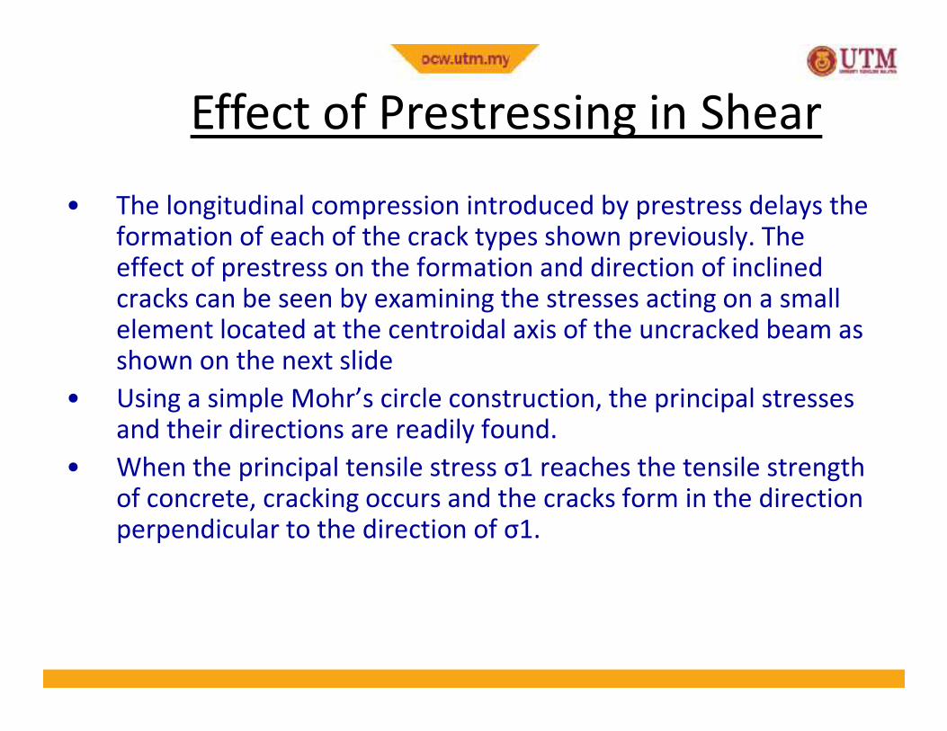
• The longitudinal compression introduced by prestress delays the formation of each of the crack types shown previously. The effect of prestress on the formation and direction of inclined cracks can be seen by examining the stresses acting on a small element located at the centroidal axis of the uncracked beam as shown on the next slide
6
shown on the next slide
• Using a simple Mohr’s circle construction, the principal stresses and their directions are readily found.
• When the principal tensile stress σ1 reaches the tensile strength of concrete, cracking occurs and the cracks form in the direction perpendicular to the direction of σ1.

= V Ay/Ib
Effect of Prestressing in Shear
7
Effect of Prestressing in Shear
• When the prestress is zero, σ1 is equal to the shear stress and acts at 45° to the beam axis. If diagonal cracking occurs, it will be perpendicular to the principal tensile stress, i.e. at 45° to the beam axis
• When the prestress is not zero, the normal compressive stress σ(=P/A) reduces the principal tension σ1. The angle between the principal stress direction and the beam axis increases, and
8
principal stress direction and the beam axis increases, and consequently if cracking occurs, the inclined crack is flatter. Prestress therefore improves the effectiveness of any transverse reinforcement (stirrups) that may be used to increase the shear strength of a beam.
• With prestress causing the inclined crack to be flatter, a larger number of the vertical stirrup legs are crossed by the crack and consequently a larger tensile force can be carried across the crack.
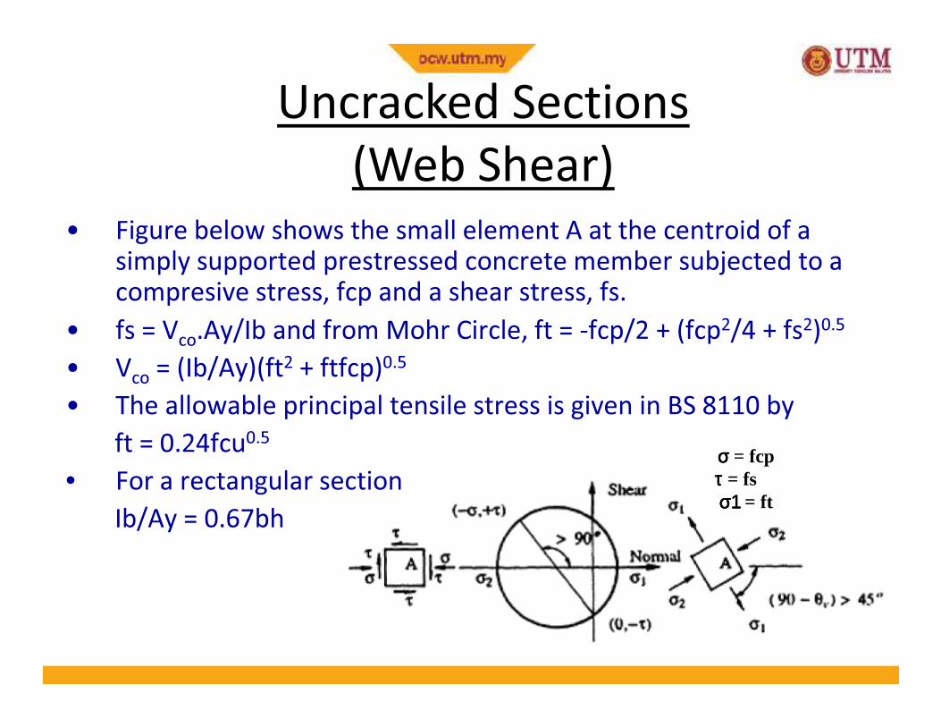
Uncracked Sections
(Web Shear)
• Figure below shows the small element A at the centroid of a simply supported prestressed concrete member subjected to a compresive stress, fcp and a shear stress, fs.
• fs = Vco
.Ay/Ib and from Mohr Circle, ft = -fcp/2 + (fcp2/4 + fs2)0.5
• V = (Ib/Ay)(ft2 + ftfcp)0.5
9
σσσσ = fcpτ τ τ τ = fsσ1σ1σ1σ1 = ft
• Vco
= (Ib/Ay)(ft2 + ftfcp)0.5
• The allowable principal tensile stress is given in BS 8110 by
ft = 0.24fcu0.5
• For a rectangular section
Ib/Ay = 0.67bh
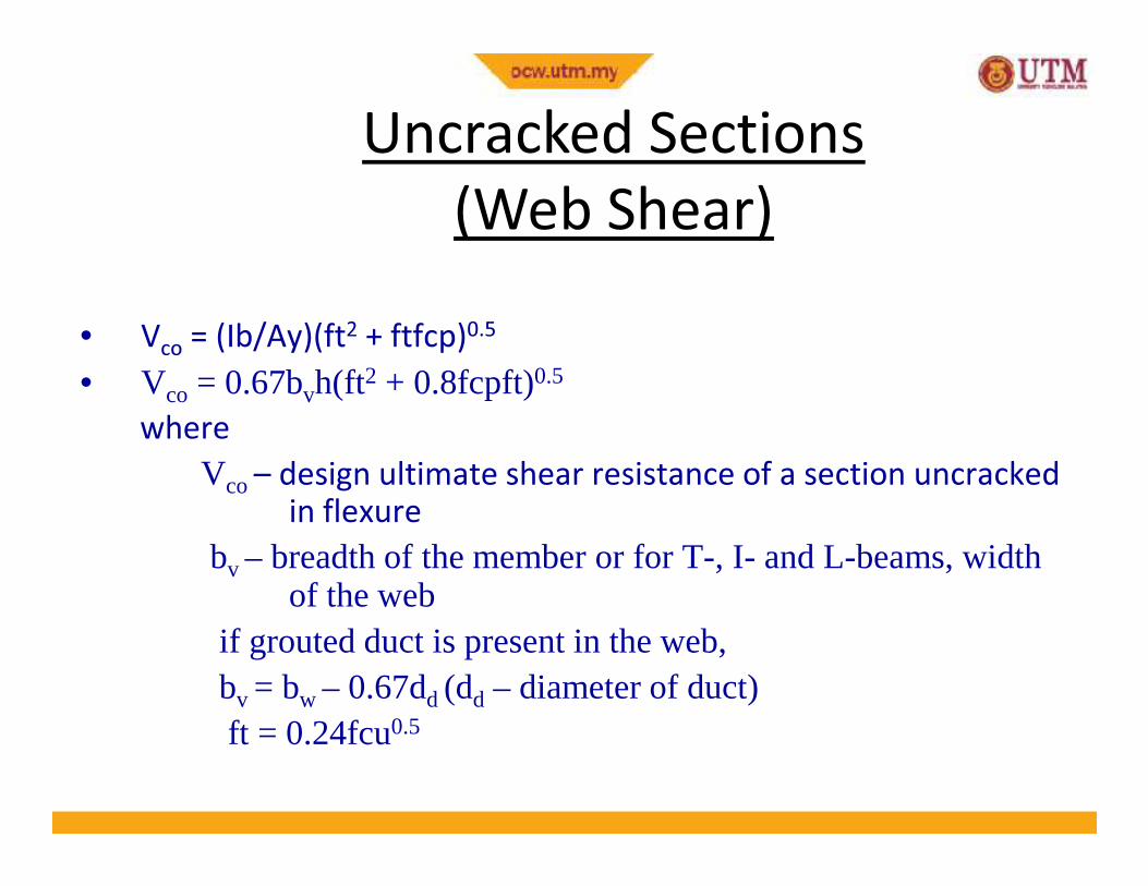
Uncracked Sections
(Web Shear)
• Vco
= (Ib/Ay)(ft2 + ftfcp)0.5
• Vco = 0.67bvh(ft2 + 0.8fcpft)0.5
where
10
where
Vco– design ultimate shear resistance of a section uncrackedin flexure
bv – breadth of the member or for T-, I- and L-beams, width of the web
if grouted duct is present in the web,bv = bw – 0.67dd (dd – diameter of duct)ft = 0.24fcu0.5
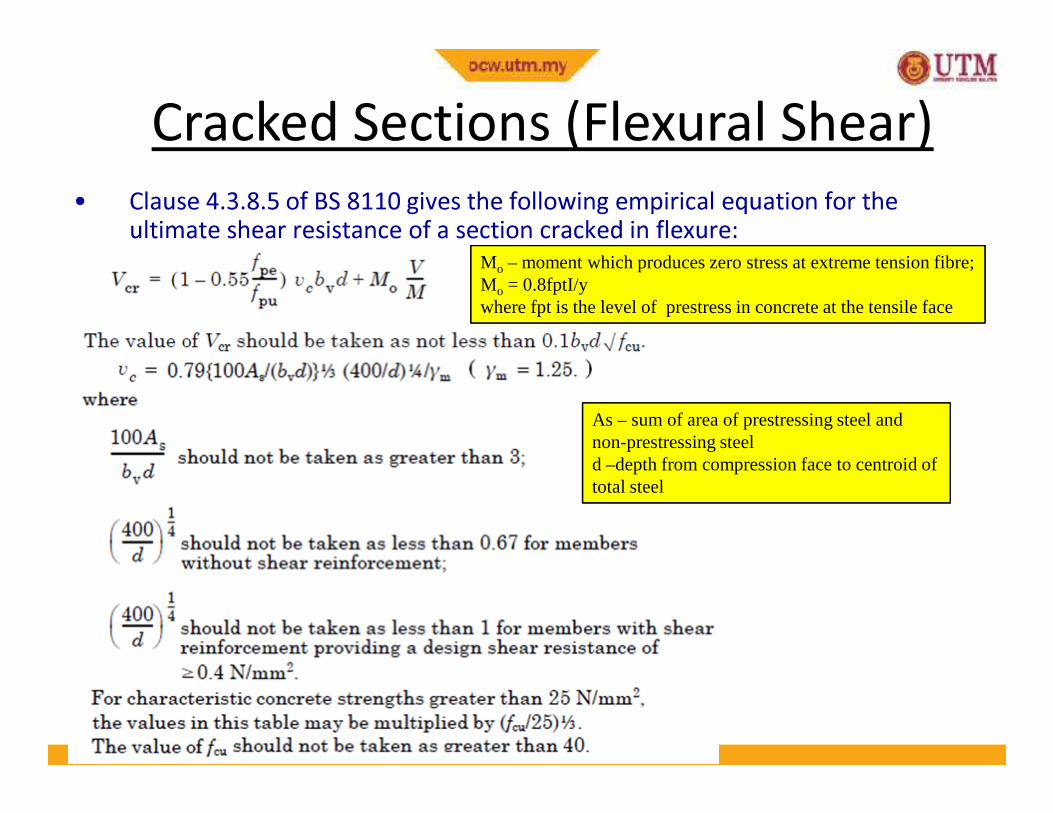
Cracked Sections (Flexural Shear)
• Clause 4.3.8.5 of BS 8110 gives the following empirical equation for the
ultimate shear resistance of a section cracked in flexure:
Mo – moment which produces zero stress at extreme tension fibre; Mo = 0.8fptI/y where fpt is the level of prestress in concrete at the tensile face
11
As – sum of area of prestressing steel and non-prestressing steeld –depth from compression face to centroid oftotal steel

Design Ultimate Shear Resistance,Vc
• According to Clause 4.3.8.3 BS 8110,Vc = Vco at uncracked section (M < Mo)Vc = is the smaller of Vco and Vcr at cracked section (M >= Mo)
• For deflected tendon, the vertical component of the prestressingforce will help to resist the shear force.
12
force will help to resist the shear force. • The total shear resistance then becomes:
Vc + Pe sin α where α is the angle of inclination of the prestressing tendon
• For Parabolic Profile, e(x) = (- 4δ/L2)x2 + (4δ/L)xα(x) = (-8d/L2)x + (4δ/L) in radian
whereδ = abs(es – ems)

Parabolic Profile
Parabola Equation: e(x) = - (4δδδδ/L2) x2 + (4δδδδ/L) x
αααα(x) = - (8δδδδ/L2) x + (4δδδδ/L)
13
δδδδα (α (α (α (
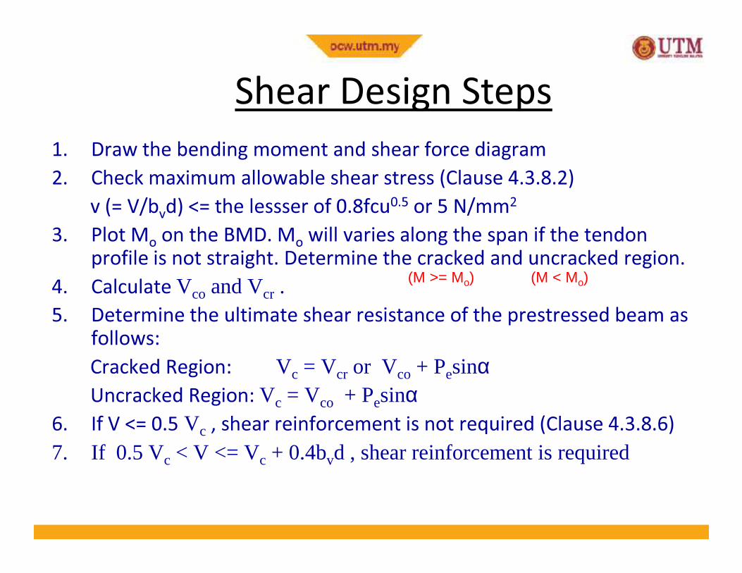
Shear Design Steps
1. Draw the bending moment and shear force diagram
2. Check maximum allowable shear stress (Clause 4.3.8.2)
v (= V/bvd) <= the lessser of 0.8fcu0.5 or 5 N/mm2
3. Plot Mo
on the BMD. Mo
will varies along the span if the tendon profile is not straight. Determine the cracked and uncracked region.
4. Calculate Vco and Vcr . (M >= Mo) (M < Mo)
14
4. Calculate Vco and Vcr . 5. Determine the ultimate shear resistance of the prestressed beam as
follows:
Cracked Region: Vc = Vcr or Vco + PesinαUncracked Region: Vc = Vco + Pesinα
6. If V <= 0.5 Vc , shear reinforcement is not required (Clause 4.3.8.6)
7. If 0.5 Vc < V <= Vc + 0.4bvd , shear reinforcement is required

Shear Design Steps
6. If V <= 0.5 Vc , shear reinforcement is not required (Clause 4.3.8.6)
7. If 0.5 Vc < V <= Vc + 0.4bvd , shear reinforcement is required (Clause 4.3.8.7). Use Asv/Sv = 0.4bv/0.87fyv
8. If V > Vc + 0.4bvd , shear reinforcement is required (Clause 4.3.8.8). Use Asv/Sv = (V – Vc)/0.87fyvdt
15
Where dt is the depth from the extreme compression fibre either to the longitudinal bars or to the centroid of the tendons, whichever is the greater
9. Sv ≯ the lesser of 0.75dt or 4*web thickness 10. When V > 1.8Vc, the maximum spacing should be reduced to 0.5dt.11. The lateral spacing of the individual legs of the links provided at a
cross-section should not exceed dt

Example 8-1
The beam shown below supports an ultimate load, including self weight of 85kN/m over a span of 15m and has a final prestress force of 2000kN. Determine the shear reinforcement required. Use the following data:
fcu = 40N/mm2; A = 2.9 x 105 mm2 ; I = 3.54 x 1010 mm4
Aps = 2010 mm2 ; fpe/fpu = 0.6
16
Aps = 2010 mm ; fpe/fpu = 0.6

Solution
1. Draw BMD and SFD
• M(x)=0.5w(Lx-x2) & V(x)=w(0.5L – x) where w = 85 kN/m
17
2. Check maximum allowable shear stress (Clause 4.3.8.2)• V = 637.5 kN, v = 637.5*103/(500*500) = 2.55 N/mm2
• vmax = lesser of (0.8*400.5 = 5.06N/mm2 and 5N/mm2) � ok3. Plot Mo on BMD.
• Mo = 0.8fpt I/y & fpt = Pe/A + P
ee /Z
2
• e(x) = (- 4δ/L2)x2 + (4δ/L)x where δ = 425mm

M < Mo ; Section Uncracked in Flexure
Solution
18
M > Mo ; Section Cracked in Flexure
M < Mo ; Section Uncracked in Flexure
Steps 4 to 8
Solution
19
Vp = PeSin αααα
Solution
20
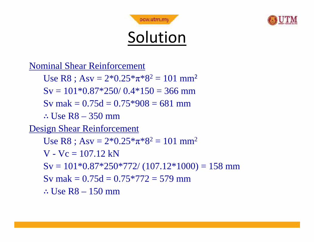
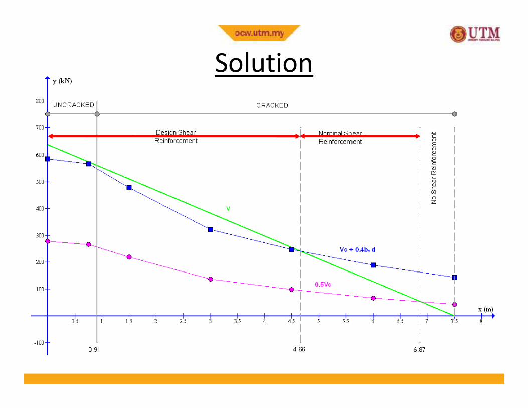
Nominal Shear ReinforcementUse R8 ; Asv = 2*0.25*π*82 = 101 mm2
Sv = 101*0.87*250/ 0.4*150 = 366 mmSv mak = 0.75d = 0.75*908 = 681 mm∴ Use R8 – 350 mm
Solution
21
∴
Design Shear ReinforcementUse R8 ; Asv = 2*0.25*π*82 = 101 mm2
V - Vc = 107.12 kNSv = 101*0.87*250*772/ (107.12*1000) = 158 mmSv mak = 0.75d = 0.75*772 = 579 mm∴ Use R8 – 150 mm
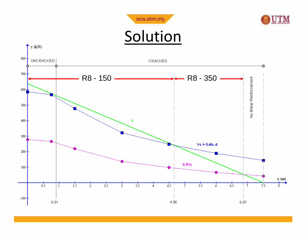
R8 - 150 R8 - 350
Solution
22

Example 8-2
A prestressed concrete T-beam shown on next slide is simply supported over a span of 28m, has been designed to carry, in addition to its own weight, a characteristic dead load of 4 kN/m and a characteristic imposed load of 10 kN/m. The beam is pre-tensioned with 14 Nos 15.7 mm diameter 7-wire super strands (Aps = 150 mm2) but due to debonding only 7 of the strands are active at a section 2 m from the support. The effective prestressing force for these 7 strands
23
from the support. The effective prestressing force for these 7 strands is 1044 kN. Use the following data:
fcu = 50 N/mm2; A = 5.08 x 105 mm2 ; I = 134 x 109 mm4;
y2
= 912 mm; fpu = 1770 N/mm2 ; fyv = 250 N/mm2
Design the section for shear.
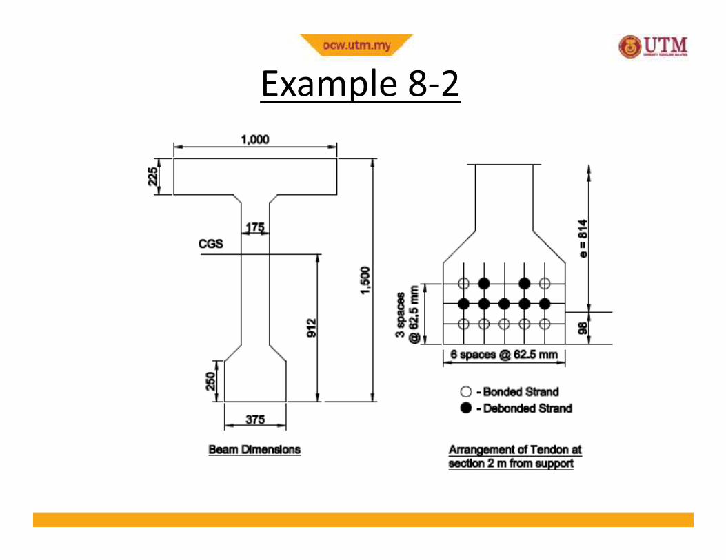
Example 8-2
24
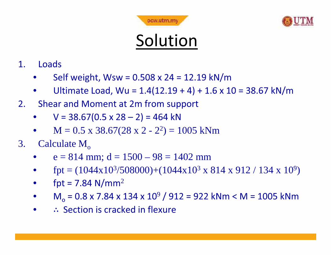
Solution
1. Loads
• Self weight, Wsw = 0.508 x 24 = 12.19 kN/m
• Ultimate Load, Wu = 1.4(12.19 + 4) + 1.6 x 10 = 38.67 kN/m
2. Shear and Moment at 2m from support
• V = 38.67(0.5 x 28 – 2) = 464 kN
• M = 0.5 x 38.67(28 x 2 - 22) = 1005 kNm
25
• M = 0.5 x 38.67(28 x 2 - 22) = 1005 kNm3. Calculate Mo
• e = 814 mm; d = 1500 – 98 = 1402 mm• fpt = (1044x103/508000)+(1044x103 x 814 x 912 / 134 x 109)• fpt = 7.84 N/mm2
• Mo
= 0.8 x 7.84 x 134 x 109 / 912 = 922 kNm < M = 1005 kNm
• ∴ Section is cracked in flexure

4. Calculation of Vco
• Vco = 0.67bvh(ft2 + 0.8fcpft)0.5
• fcp = 1044 x 103/50800 = 2.06 N/mm2
• ft = 0.24 x 500.5 = 1.70 N/mm2 ; h = 1500 mm; bv = 175 mm
• Vco = 0.67x175x1500(1.702 + 0.8x2.06x1.70)0.5 /103 = 420 kN
5. Calculation of Vcr
Solution
26
5. Calculation of Vcr• fpe = 1044 x 103 / 7 x 150 = 994 N/mm2
• 100As/bvd= 100x7x150/175x1402 = 0.43 <= 3 ok• 400/d = 400/1402 = 0.29 < 1 use 400/d = 1• fcu = 50 N/mm2 > 40 N/mm2; Use fcu = 40 N/mm2
• vc = 0.79 x 0.431/3 x 1 x (40/25)1/3 /1.25 = 0.556 N/mm2
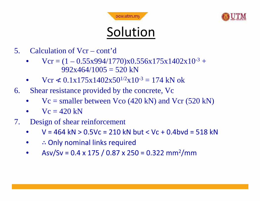
5. Calculation of Vcr – cont’d• Vcr = (1 – 0.55x994/1770)x0.556x175x1402x10-3 +
992x464/1005 = 520 kN• Vcr ≮ 0.1x175x1402x501/2x10-3 = 174 kNok
6. Shear resistance provided by the concrete, Vc• Vc = smaller between Vco (420 kN) and Vcr (520 kN)
Solution
27
≮
• Vc = smaller between Vco (420 kN) and Vcr (520 kN)• Vc = 420 kN
7. Design of shear reinforcement• V = 464 kN > 0.5Vc = 210 kN but < Vc + 0.4bvd = 518 kN
• ∴ Only nominal links required
• Asv/Sv = 0.4 x 175 / 0.87 x 250 = 0.322 mm2/mm

7. Design of shear reinforcement• V = 464 kN > 0.5Vc = 210 kN but < Vc + 0.4bvd = 518 kN
• ∴ Only nominal links required
• Asv/Sv = 0.4 x 175 / 0.87 x 250 = 0.322 mm2/mm
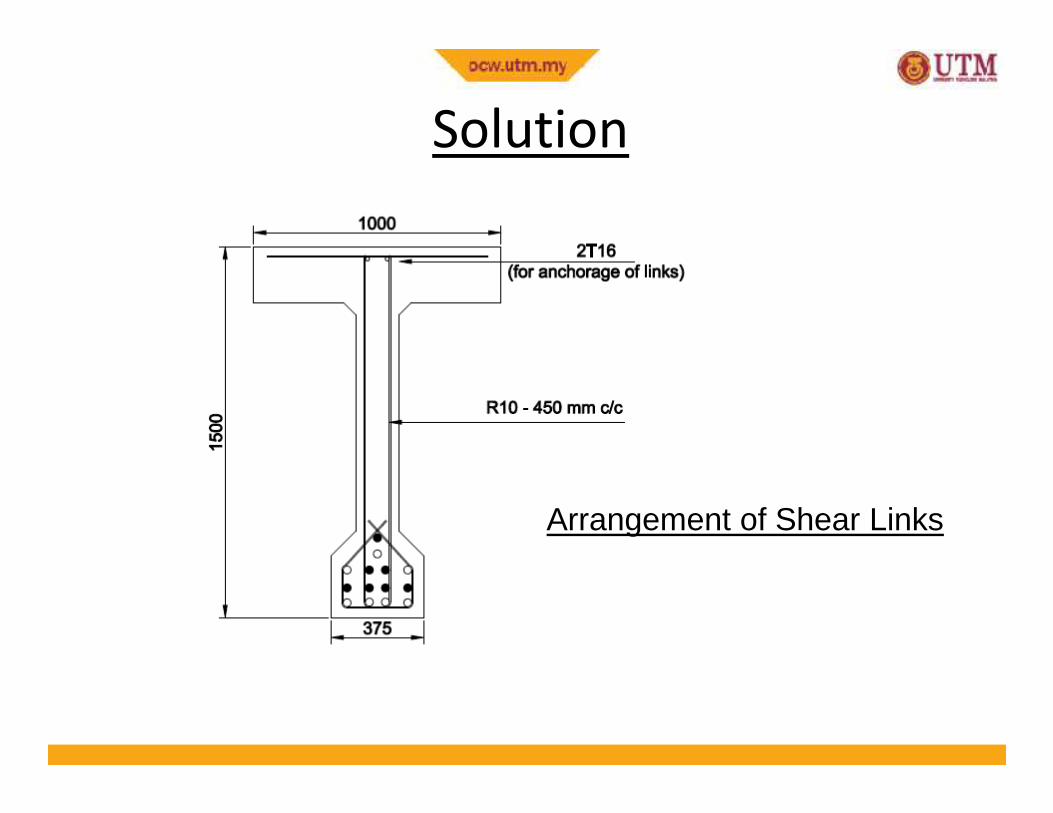
• Using 10 mm diameter stirrup/links, Asv = 157 mm2
• Sv = 157/0.322 = 487mm<0.75dt = 0.75(1500–62.5) = 1078mm
∴
Solution
28
• Sv = 157/0.322 = 487mm<0.75dt = 0.75(1500–62.5) = 1078mm
• ∴ Use R10 – 450 mm c/c
Solution
29
Arrangement of Shear Links
Shear in Composite Beams
30
Composite Beams

Introduction
Need to design for two types of shear
• Horizontal Shear At Interface between Precast and Cast
In Situ Concrete
• Vertical Shear
31
• Vertical Shear
� Both design at ULS
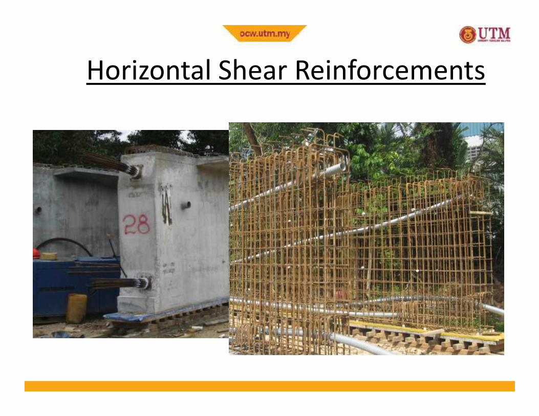
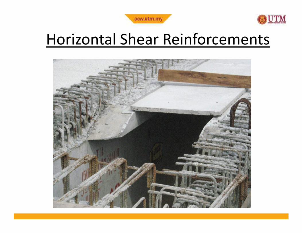
Horizontal Shear at Interface
• The composite behaviour of precast beam and in situ slab is only
effective if the horizontal shear stresses at the interface between
the two regions can be resisted
• For shallower members, there is usually no mechanical key
between the two types of concrete, and reliance is made on the
friction developed between the contact surfaces
32
friction developed between the contact surfaces
• For deeper section, mechanical shear connectors in the form of
links projecting from the beam are used
• The determination of the horizontal shear resistance is based on
the ultimate limit state, and if this condition is satisfied, it may be
assumed that satisfactory horizontal shear resistance is provided
at the serviceability limit state
Horizontal Shear Reinforcements
33
Horizontal Shear Reinforcements
34

Horizontal Shear Reinforcements
35

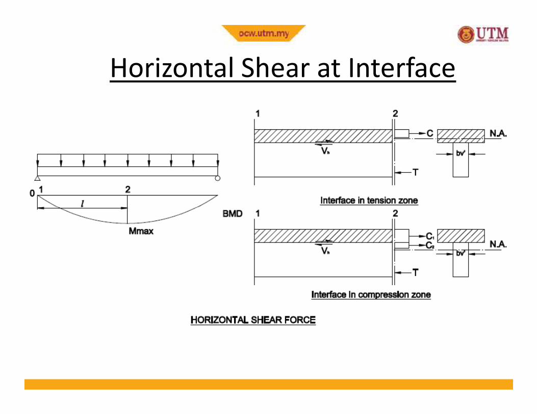
Design Horizontal Shear Force• To determine the horizontal shear force acting at the interface, the
segments of the beam between points of maximum moment and
zero moment are considered
• For a particular segment, the neutral axis position and the
distribution of stresses at the maximum moment section due to
ultimate loads acting on the beam are established by the ultimate
36
ultimate loads acting on the beam are established by the ultimate
strength analysis procedure
• Two situation may arise depending on the location of the neutral
axis. As shown on the next slide, the interface may be either in the
tension zone or in the compression zone.
• The horizontal shear force, Vh, acting at the interface can then be
calculated from horizontal equilibrium of the cast in situ
component
Horizontal Shear at Interface
37
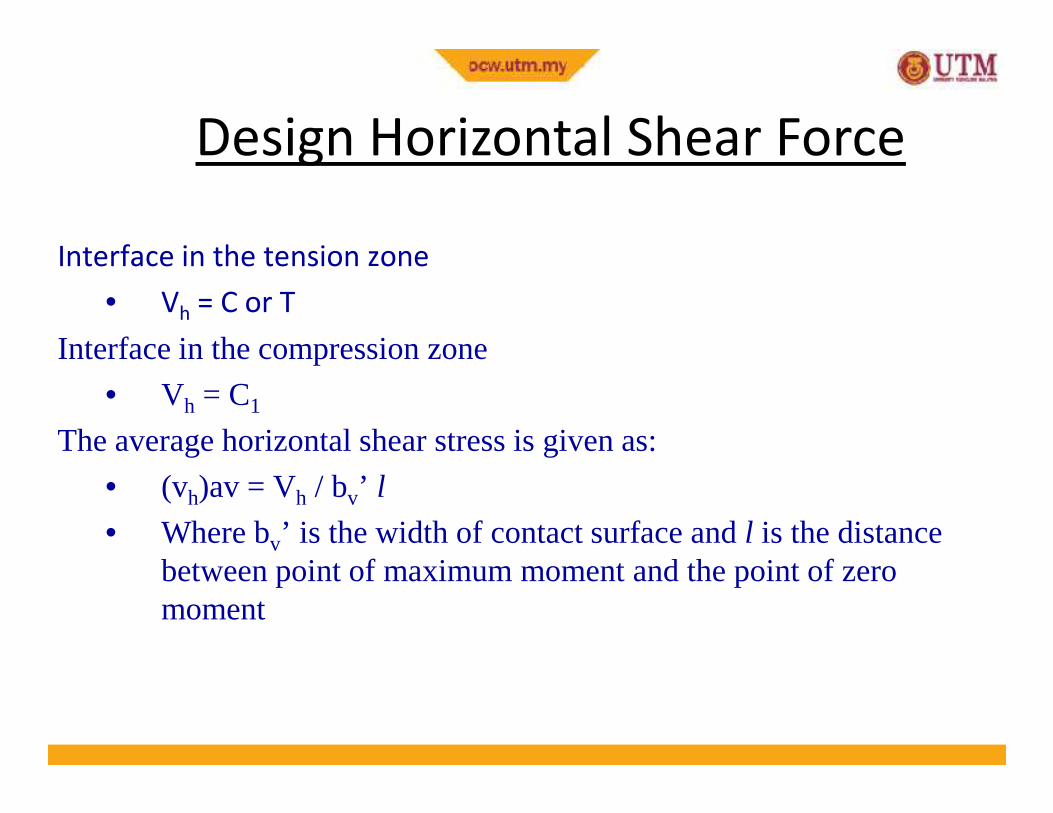
Design Horizontal Shear Force
Interface in the tension zone
• Vh
= C or T
Interface in the compression zone
• Vh = C1
38
• Vh = C1
The average horizontal shear stress is given as:
• (vh)av = Vh / bv’ l
• Where bv’ is the width of contact surface and l is the distance between point of maximum moment and the point of zero moment
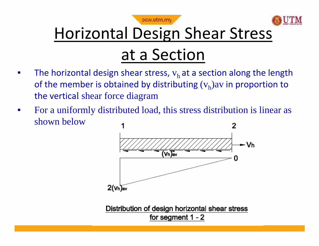
Horizontal Design Shear Stress
at a Section• The horizontal design shear stress, vh at a section along the length
of the member is obtained by distributing (vh)av in proportion to
the vertical shear force diagram
• For a uniformly distributed load, this stress distribution is linear as shown below
39
shown below
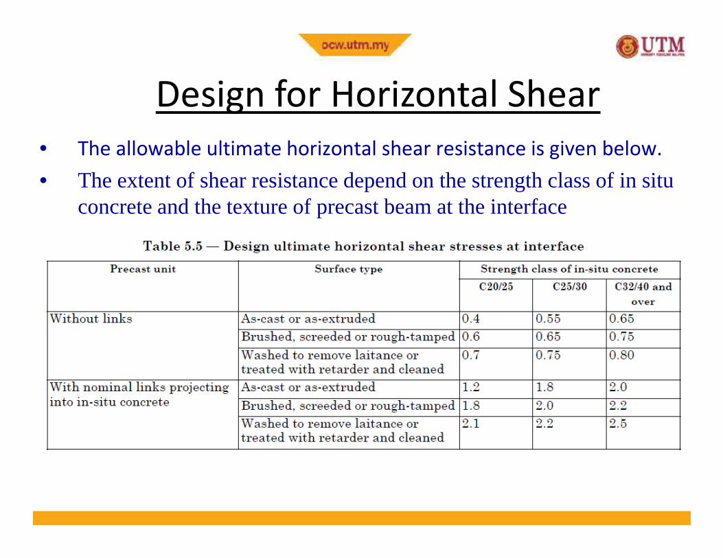
Design for Horizontal Shear
• The allowable ultimate horizontal shear resistance is given below.
• The extent of shear resistance depend on the strength class of in situ concrete and the texture of precast beam at the interface
40
Design for Horizontal Shear
• Where higher resistance to horizontal shear is needed, the beam
may be provided with nominal links that are projected through the
interface and are anchored in the cast in situ concrete
• Nominal links are defined as
• A = 0.15 x b ’ x l / 100
41
• Ah
= 0.15 x bv’ x l / 100
• Sv – the smaller between 4hfand 600 mm
• If the maximum horizontal design shear stress exceeds the
allowable values, provide the following area of steel:
• Ah = 1000 bv’ vh / 0.87fyv