pressure independence module - acutherm.com · pim™: product overview v001 – issue date:...
TRANSCRIPT
PIM
™: P
rod
uct O
verv
iew
v001 – Issue Date: 12/14/17
BENEFITS AT A GLANCE
QUIET VAV DIFFUSER OPERATION
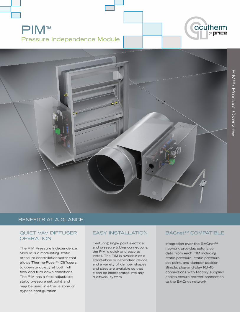
The PIM Pressure Independence Module is a modulating static pressure controller/actuator that allows Therma-FuserTM Diffusers to operate quietly at both full flow and turn down conditions. The PIM has a field adjustable static pressure set point and may be used in either a zone or bypass configuration.
EASY INSTALLATION
Featuring single point electrical and pressure tubing connections, the PIM is quick and easy to install. The PIM is available as a stand-alone or networked device and a variety of damper shapes and sizes are available so that it can be incorporated into any ductwork system.
BACnetTM COMPATIBLE
Integration over the BACnet™ network provides extensive data from each PIM including: static pressure, static pressure set point, and damper position. Simple, plug-and-play RJ-45 connections with factory supplied cables ensure correct connection to the BACnet network.
PIM™
Pressure Independence Module
PIM Pressure Independence Module
2
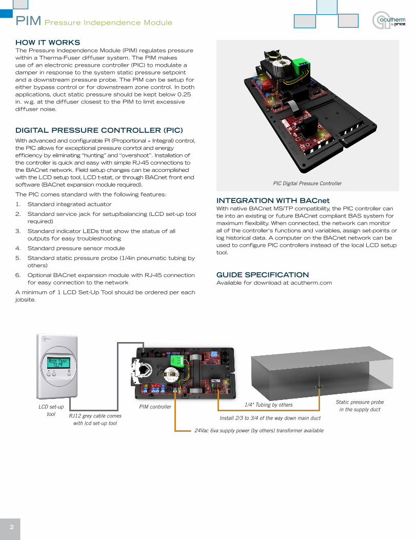
HOW IT WORKSThe Pressure Independence Module (PIM) regulates pressure within a Therma-Fuser diffuser system. The PIM makes use of an electronic pressure controller (PIC) to modulate a damper in response to the system static pressure setpoint and a downstream pressure probe. The PIM can be setup for either bypass control or for downstream zone control. In both applications, duct static pressure should be kept below 0.25 in. w.g. at the diffuser closest to the PIM to limit excessive diffuser noise.
DIGITAL PRESSURE CONTROLLER (PIC)With advanced and configurable PI (Proportional + Integral) control, the PIC allows for exceptional pressure conrtol and energy efficiency by eliminating “hunting” and “overshoot”. Installation of the controller is quick and easy with simple RJ-45 connections to the BACnet network. Field setup changes can be accomplished with the LCD setup tool, LCD t-stat, or through BACnet front end software (BACnet expansion module required).
The PIC comes standard with the following features:
1. Standard integrated actuator
2. Standard service jack for setup/balancing (LCD set-up tool required)
3. Standard indicator LEDs that show the status of all outputs for easy troubleshooting
4. Standard pressure sensor module
5. Standard static pressure probe (1/4in pneumatic tubing by others)
6. Optional BACnet expansion module with RJ-45 connection for easy connection to the network
A minimum of 1 LCD Set-Up Tool should be ordered per each jobsite.
INTEGRATION WITH BACnetWith native BACnet MS/TP compatibility, the PIC controller can tie into an existing or future BACnet compliant BAS system for maximum flexibility. When connected, the network can monitor all of the controller's functions and variables, assign set-points or log historical data. A computer on the BACnet network can be used to configure PIC controllers instead of the local LCD setup tool.
GUIDE SPECIFICATIONAvailable for download at acutherm.com
1/4" Tubing by othersPIM controllerStatic pressure probe
in the supply duct
Install 2/3 to 3/4 of the way down main duct
24Vac 6va supply power (by others) transformer available
LCD set-up tool RJ12 grey cable comes
with lcd set-up tool
PIC Digital Pressure Controller
PIM
Supply AirTemperature Sensor
Sta�c Pressure Sensor
Therma-Fuser Diffusers
BAS Computer for BACnet Op�on
Sta�c pressure probe located 2.3 or 3/4 down duct
1/4 in. pneuma�c tubing by others
Op�onal BACnet network wiring for BACnet expansion module
PIM
Sta�c pressure probe located 2.3 or 3/4 down duct
Supply AirTemperature Sensor
Therma-FuserDiffusers
BAS Computer for BACnet Op�on
AHU
1/4 in. pneuma�c tubing by others
PIM Pressure Independence Module
3
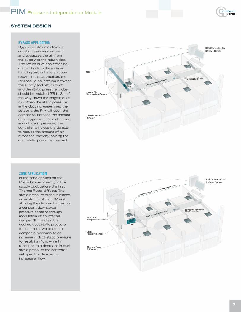
BYPASS APPLICATIONBypass control maintains a constant pressure setpoint and bypasses the air from the supply to the return side. The return duct can either be ducted back to the main air handling unit or have an open return. In this application, the PIM should be installed between the supply and return duct, and the static pressure probe should be installed 2/3 to 3/4 of the way down the longest duct run. When the static pressure in the duct increases past the setpoint, the PIM will open the damper to increase the amount of air bypassed. On a decrease in duct static pressure, the controller will close the damper to reduce the amount of air bypassed, thereby holding the duct static pressure constant.
ZONE APPLICATIONIn the zone application the PIM is located directly in the supply duct before the first Therma-Fuser diffuser. The static pressure probe is placed downstream of the PIM unit, allowing the damper to maintain a constant downstream pressure setpoint through modulation of an internal damper. To maintain the desired duct static pressure, the controller will close the damper in response to an increase in duct static pressure to restrict airflow, while in response to a decrease in duct static pressure the controller will open the damper to increase airflow.
SYSTEM DESIGN
PIM Pressure Independence Module
4
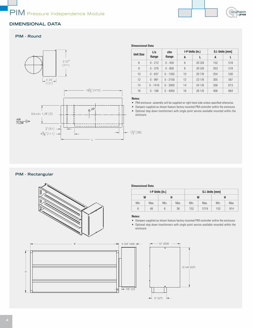
DIMENSIONAL DATA
PIM - Rectangular
PIM - Round
Notes:• PIM enclosure assembly will be supplied on right hand side unless specified otherwise.• Dampers supplied as shown feature factory mounted PIM controller within the enclosure.• Optional step down transformers with single point service available mounted within the
enclosure.
Notes:• Dampers supplied as shown feature factory mounted PIM controller within the enclosure.• Optional step down transformers with single point service available mounted within the
enclosure.
Dimensional Data
Dimensional Data
Unit SizeL/s
Rangecfm
Range
I-P Units (in.) S.I. Units [mm]
A L A L
6 0 - 212 0 - 450 6 20 3/8 152 518
8 0 - 378 0 - 800 8 20 3/8 203 518
10 0 - 637 0 - 1350 10 20 7/8 254 530
12 0 - 991 0 - 2100 12 23 1/8 305 587
14 0 - 1416 0 - 3000 14 24 1/8 356 613
16 0 - 188 0 - 4000 16 26 1/8 406 664
ALL METRIC DIMENSIONS ( ) ARE SOFT CONVERTED. IMPERIAL DIMENSIONS ARE CONVERTED TO METRIC AND ROUNDED TO THE NEAREST MILLIMETER.
0
PIMSQAURE DAMPER
268755
PROJECT:
ENGINEER:
CUSTOMER:
SUBMITTAL DATE: SPEC. SYMBOL:
Submittal Sheet
AUG 2017OF REVSHEET 1 1© Copyright PRICE INDUSTRIES 2012
Solid
Edg
e
W
H
5 3/4" (146) 9 7/8" (251)
13 1/4' (337)
5" (127)
MIN MAX MIN MAX6" (152) 48" (1219) 6" (152) 36" (914)
W HDAMPER DIMENSIONS
STANDARD CONSTRUCTION: FRAME: ROLL-FORMED 20 GA. GALV STEEL HAT SECTION
WITH STAKED CORNERS WITH INTERGRAL BRACING BLADES: 16 GA. GALV STEEL ROLL FORMED, TRIPLE VEE PROFILE
•
•
7/8" (22)
OPTIONS: LOW LEAKAGE SEALS
I-P Units [in.] S.I. Units [mm]
W H W H
Min. Max. Min. Max. Min. Max. Min. Max.
6 48 6 36 152 1219 152 914
ALL METRIC DIMENSIONS ( ) ARE SOFT CONVERTED. IMPERIAL DIMENSIONS ARE CONVERTED TO METRIC AND ROUNDED TO THE NEAREST MILLIMETER.
0
PIMSQAURE DAMPER
268755
PROJECT:
ENGINEER:
CUSTOMER:
SUBMITTAL DATE: SPEC. SYMBOL:
Submittal Sheet
AUG 2017OF REVSHEET 1 1© Copyright PRICE INDUSTRIES 2012
Solid
Edg
e
W
H
13 1/4' (337)
5" (127)
MIN MAX MIN MAX6" (152) 48" (1219) 6" (152) 36" (914)
W HDAMPER DIMENSIONS
STANDARD CONSTRUCTION: FRAME: ROLL-FORMED 20 GA. GALV STEEL HAT SECTION
WITH STAKED CORNERS WITH INTERGRAL BRACING BLADES: 16 GA. GALV STEEL ROLL FORMED, TRIPLE VEE PROFILE
•
•
OPTIONS: LOW LEAKAGE SEALS
5 3/4" (146)
7/8" (22)
10" (254)
PIM Pressure Independence Module
5
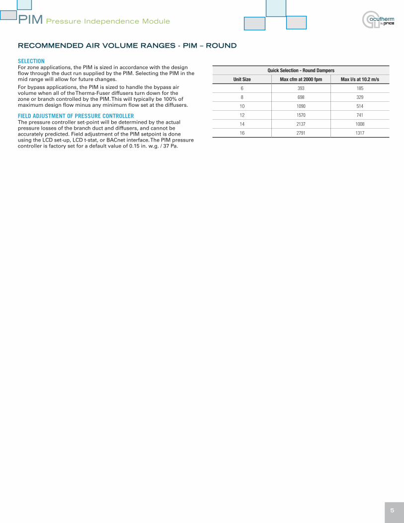
RECOMMENDED AIR VOLUME RANGES - PIM – ROUND
SELECTIONFor zone applications, the PIM is sized in accordance with the design flow through the duct run supplied by the PIM. Selecting the PIM in the mid range will allow for future changes.
For bypass applications, the PIM is sized to handle the bypass air volume when all of the Therma-Fuser diffusers turn down for the zone or branch controlled by the PIM. This will typically be 100% of maximum design flow minus any minimum flow set at the diffusers.
FIELD ADJUSTMENT OF PRESSURE CONTROLLERThe pressure controller set-point will be determined by the actual pressure losses of the branch duct and diffusers, and cannot be accurately predicted. Field adjustment of the PIM setpoint is done using the LCD set-up, LCD t-stat, or BACnet interface. The PIM pressure controller is factory set for a default value of 0.15 in. w.g. / 37 Pa.
Quick Selection - Round Dampers
Unit Size Max cfm at 2000 fpm Max l/s at 10.2 m/s
6 393 185
8 698 329
10 1090 514
12 1570 741
14 2137 1008
16 2791 1317
PIM Pressure Independence Module
6
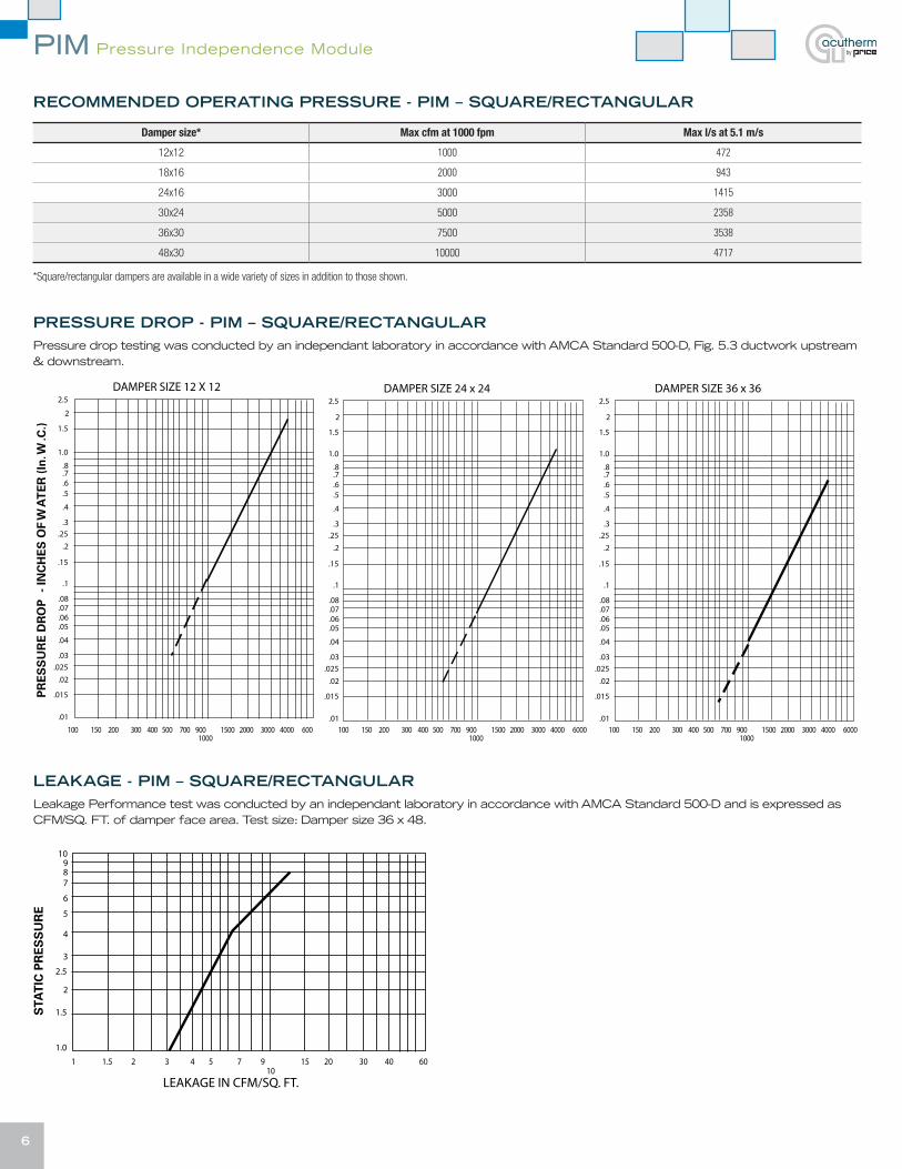
RECOMMENDED OPERATING PRESSURE - PIM – SQUARE/RECTANGULAR
Damper size* Max cfm at 1000 fpm Max l/s at 5.1 m/s
12x12 1000 472
18x16 2000 943
24x16 3000 1415
30x24 5000 2358
36x30 7500 3538
48x30 10000 4717
*Square/rectangular dampers are available in a wide variety of sizes in addition to those shown.
PRESSURE DROP - PIM – SQUARE/RECTANGULARPressure drop testing was conducted by an independant laboratory in accordance with AMCA Standard 500-D, Fig. 5.3 ductwork upstream & downstream.
LEAKAGE - PIM – SQUARE/RECTANGULAR Leakage Performance test was conducted by an independant laboratory in accordance with AMCA Standard 500-D and is expressed as CFM/SQ. FT. of damper face area. Test size: Damper size 36 x 48.
5 All Metric dimensions ( ) are soft conversion. © Copyright E.H. Price Limited 2012. Imperial dimensions are converted to metric and rounded to the nearest millimetre.
Model CCD-GV5-3V-LLSteel ConstructionLow Leakage Model
Commercial Control Damper - Steel
AT AT ATLEAKAGE 1.0" w.g. 2.5" w.g. 4.0" w.g.
cfm/SQ. FT. 3.5 5.0 7.0
Jul / 12 244965 SHEET 2 OF 2 Rev.A

PIM Pressure Independence Module
7
BALANCING PROCEDUREThe objective when balancing a system with Therma-Fuser diffusers is to ensure that design airflow is achieved at the diffuser with the highest pressure drop (typically the last diffuser downstream of the PIM), ensure that the static pressure at the inlet to the diffuser with the lowest pressure drop (typically the diffuser closest to the PIM) does not exceed 0.25”wg / 62Pa and to do so at the lowest possible static pressure to minimize the fan energy used. Satisfying the first two conditions will allow the Therma-Fuser diffusers to modulate and control each space in a quiet and energy efficient manner.
PROPORTIONAL BALANCING PROCEDURE
1. Adjust the fan speed to 100%
2. Adjust each PIM zone independently. Each PIM (and the diffusers downstream) is balanced as an independent zone and the PIM static pressure set point adjusted to maintain the design airflow at the Therma-Fuser diffuser with the highest pressure drop.
a. Adjust the PIM set point to 0.15”wg / 37Pa.
b. Open all Therma-Fuser diffusers in the PIM zone (see individual model of diffuser for opening instructions).
c. Ensure all manual volume (balancing) dampers are 100% open.
d. Allow a little time (5-10 minutes) for the PIM to control to the set point.
e. Measure the airflow at each diffuser.
f. Compare the measured airflow with the design airflow for each space and:
i. Determine which diffuser is the lowest with respect to the design airflow. This is the diffuser with the highest pressure drop.
ii. Determine which diffuser is the highest with respect to the design airflow. This is the diffuser with the lowest pressure drop.
g. Do not close the manual damper on the diffuser with the highest pressure drop. Keep this damper 100% open.
h. Adjust the manual volume damper on each of the other diffuser to match the percentage from the design airflow as that of the diffuser with the highest pressure drop.
i. Adjust the PIM set point until design airflow (+10% / -5%) is achieved at the diffuser with the highest pressure drop. Allow a little time (5-10 minutes) for the PIM to control to the set point.
j. Check the static pressure at the takeoff to the diffuser with the lowest pressure drop (static pressure should be less than or equal to 0.25”wg / 62Pa).
k. Check the remaining diffusers on the PIM zone to ensure all are supplying greater than or equal to design airflow.
l. Note the PIM set point.
m. Return all Therma-Fuser diffusers in the zone to operation (see individual model for instructions).
3. Repeat for each PIM zone on the system.
4. Adjust the fan speed. Once each PIM zone has been balanced and the PIM set points adjusted, identify the PIM zone with the highest pressure drop (typically the zone furthest from the fan or the PIM with the damper open the furthest).
a. Open all Therma-Fuser diffusers in the PIM zone (see individual model of diffuser for opening instructions).
b. Establish the static pressure set point for the fan speed control by turning it down to the slowest speed that will maintain the design airflow at the highest pressure drop diffuser in the highest pressure drop PIM zone (PIM damper should be open to almost 100%).
c. Return all Therma-Fuser diffusers in the zone to operation (see individual model for instructions).
NOTE: Diffuser noise is caused by higher velocity air through the diffuser which is caused by a high static pressure. Acutherm recommends a static pressure no higher than 0.25”wg / 62Pa at the inlet to the diffuser. Some system designers may accept higher noise levels and opt for a higher static pressure. Care should be taken not to exceed the design maximum static pressure at the takeoff to the first diffuser after the PIM.
Square VAV Diffusers Round VAV Diffusers Linear VAV Diffusers Options and Accessories Pressure Control
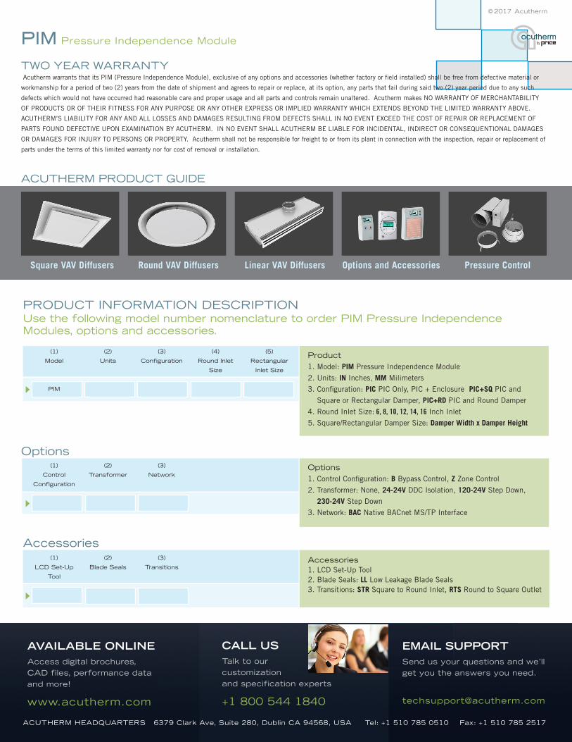
TWO YEAR WARRANTY Acutherm warrants that its PIM (Pressure Independence Module), exclusive of any options and accessories (whether factory or field installed) shall be free from defective material or
workmanship for a period of two (2) years from the date of shipment and agrees to repair or replace, at its option, any parts that fail during said two (2) year period due to any such
defects which would not have occurred had reasonable care and proper usage and all parts and controls remain unaltered. Acutherm makes NO WARRANTY OF MERCHANTABILITY
OF PRODUCTS OR OF THEIR FITNESS FOR ANY PURPOSE OR ANY OTHER EXPRESS OR IMPLIED WARRANTY WHICH EXTENDS BEYOND THE LIMITED WARRANTY ABOVE.
ACUTHERM’S LIABILITY FOR ANY AND ALL LOSSES AND DAMAGES RESULTING FROM DEFECTS SHALL IN NO EVENT EXCEED THE COST OF REPAIR OR REPLACEMENT OF
PARTS FOUND DEFECTIVE UPON EXAMINATION BY ACUTHERM. IN NO EVENT SHALL ACUTHERM BE LIABLE FOR INCIDENTAL, INDIRECT OR CONSEQUENTIONAL DAMAGES
OR DAMAGES FOR INJURY TO PERSONS OR PROPERTY. Acutherm shall not be responsible for freight to or from its plant in connection with the inspection, repair or replacement of
parts under the terms of this limited warranty nor for cost of removal or installation.
PRODUCT INFORMATION DESCRIPTION Use the following model number nomenclature to order PIM Pressure Independence Modules, options and accessories.
OptionsOptions1. Control Configuration: B Bypass Control, Z Zone Control
2. Transformer: None, 24-24V DDC Isolation, 120-24V Step Down,
230-24V Step Down
3. Network: BAC Native BACnet MS/TP Interface
(1)
Control
Configuration
(2)
Transformer
(3)
Network
Accessories1. LCD Set-Up Tool2. Blade Seals: LL Low Leakage Blade Seals 3. Transitions: STR Square to Round Inlet, RTS Round to Square Outlet
Accessories(1)
LCD Set-Up
Tool
(2)
Blade Seals
(3)
Transitions
Product1. Model: PIM Pressure Independence Module
2. Units: IN Inches, MM Milimeters
3. Configuration: PIC PIC Only, PIC + Enclosure PIC+SQ PIC and
Square or Rectangular Damper, PIC+RD PIC and Round Damper
4. Round Inlet Size: 6, 8, 10, 12, 14, 16 Inch Inlet
5. Square/Rectangular Damper Size: Damper Width x Damper Height
(1)
Model
PIM
(2)
Units
(3)
Configuration
(4)
Round Inlet
Size
(5)
Rectangular
Inlet Size
© 2017 Acutherm
ACUTHERM PRODUCT GUIDE
ACUTHERM HEADQUARTERS 6379 Clark Ave, Suite 280, Dublin CA 94568, USA Tel: +1 510 785 0510 Fax: +1 510 785 2517
AVAILABLE ONLINEAccess digital brochures, CAD files, performance data and more!
www.acutherm.com
CALL USTalk to our customization and specification experts
+1 800 544 1840
EMAIL SUPPORTSend us your questions and we’ll get you the answers you need.
PIM Pressure Independence Module