pressure governor and engine monitoring model… · pressure governor and engine monitoring model:...
TRANSCRIPT

PBA400 Rev171103
1
FIRE RESEARCH CORPORATIONwww.fireresearch.com
26 Southern Blvd., Nesconset, NY 11767TEL 631.724.8888 FAX 631.360.9727 TOLL FREE 1.800.645.0074
PRESSURE GOVERNORand ENGINE MONITORING
MODEL: PBA400
Document Number:XE-PBA4PM-R0A
PBA400 Rev171103
2
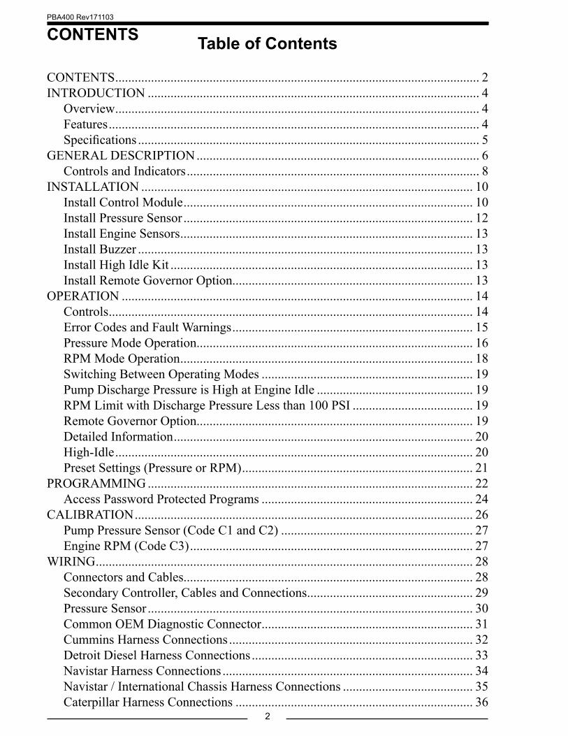
CONTENTS Table of Contents
CONTENTS ................................................................................................................ 2INTRODUCTION ...................................................................................................... 4
Overview ................................................................................................................ 4Features .................................................................................................................. 4Specifications ......................................................................................................... 5
GENERAL DESCRIPTION ....................................................................................... 6Controls and Indicators .......................................................................................... 8
INSTALLATION ...................................................................................................... 10Install Control Module ......................................................................................... 10Install Pressure Sensor ......................................................................................... 12Install Engine Sensors .......................................................................................... 13Install Buzzer ....................................................................................................... 13Install High Idle Kit ............................................................................................. 13Install Remote Governor Option.......................................................................... 13
OPERATION ............................................................................................................ 14Controls ................................................................................................................ 14Error Codes and Fault Warnings .......................................................................... 15Pressure Mode Operation..................................................................................... 16RPM Mode Operation .......................................................................................... 18Switching Between Operating Modes ................................................................. 19Pump Discharge Pressure is High at Engine Idle ................................................ 19RPM Limit with Discharge Pressure Less than 100 PSI ..................................... 19Remote Governor Option..................................................................................... 19Detailed Information ............................................................................................ 20High-Idle .............................................................................................................. 20Preset Settings (Pressure or RPM) ....................................................................... 21
PROGRAMMING .................................................................................................... 22Access Password Protected Programs ................................................................. 24
CALIBRATION ........................................................................................................ 26Pump Pressure Sensor (Code C1 and C2) ........................................................... 27Engine RPM (Code C3) ....................................................................................... 27
WIRING .................................................................................................................... 28Connectors and Cables......................................................................................... 28Secondary Controller, Cables and Connections ................................................... 29Pressure Sensor .................................................................................................... 30Common OEM Diagnostic Connector ................................................................. 31Cummins Harness Connections ........................................................................... 32Detroit Diesel Harness Connections .................................................................... 33Navistar Harness Connections ............................................................................. 34Navistar / International Chassis Harness Connections ........................................ 35Caterpillar Harness Connections ......................................................................... 36

PBA400 Rev171103
3
List of Tables
Table 1. Pressure Sensor Output Voltage ................................................................... 5Table 2. Error Codes ................................................................................................ 15Table 3. Fault Warning Codes .................................................................................. 15Table 4. Operator Password Protected Program Functions ..................................... 25Table 5. Calibration Codes Quick Reference Chart ................................................. 26
List of Figures
Figure 1. Controls and Indicators ............................................................................... 9Figure 2. Control Module Mounting Dimensions.................................................... 11Figure 3. Pressure Sensor Dimensions ..................................................................... 12Figure 4. PBA Connectors ....................................................................................... 28Figure 5. PBA Connector Wiring ............................................................................. 29Figure 6. Pressure Sensor Wiring ............................................................................. 30Figure 7. Common OEM 9-Pin Diagnostic Connector ............................................ 31Figure 8. Cummins PBA401 Wiring ........................................................................ 32Figure 9. Detroit Diesel PBA402 Wiring ................................................................. 33Figure 10. Navistar PBA404 Wiring ......................................................................... 34Figure 11. Navistar/International Chassis PBA404 Wiring ...................................... 35Figure 12. Caterpillar PBA405 Wiring ..................................................................... 36Figure 13. Ford PBA406 J1939 Translator Module Wiring ..................................... 38Figure 14. Ford PBA406 PCM Wiring ..................................................................... 39Figure 15. Mack PBA407 Wiring ............................................................................. 40Figure 16. Scania PBA408 Wiring—Type A ............................................................ 41Figure 17. Scania BCI PBA408 Wiring—Type D .................................................... 42Figure 18. Mercedes PBA410 Wiring ....................................................................... 43Figure 19. John Deere PBA416 Wiring .................................................................... 44Figure 20. MAN PBA424 Wiring ............................................................................. 45Figure 21. IVECO PBA426 Wiring .......................................................................... 46Figure 22. High-Idle Wiring ..................................................................................... 47Figure 23. Flyback Diode ........................................................................................ 48
Ford Harness Connections ................................................................................... 37Mack Harness Connections ................................................................................. 40Scania Harness Connections—Type A ................................................................ 41Scania BCI Harness Connections—Type D ........................................................ 42Mercedes Harness Connections ........................................................................... 43John Deere Harness Connections ........................................................................ 44MAN Harness Connections ................................................................................. 45IVECO Harness Connections .............................................................................. 46High-Idle Wiring .................................................................................................. 47FLYBACK DIODE INFORMATION ................................................................. 48

PBA400 Rev171103
4
INTRODUCTION
OverviewThe Fire Research pressure governor uses state-of-the-art-programmable
microprocessor technology and operates in one of two modes, pressure or RPM. It maintains a steady pump discharge pressure within system capabilities by controlling the engine speed or holds a selected engine RPM.
The PBA400 has two pressure sensors that monitor both the pump intake and discharge pressure. The duel sensor configuration provides improved defense against pump cavitations.
In pressure mode the governor maintains a constant pump discharge pressure. The discharge pressure is monitored and compared to the selected pressure setting, the engine RPM is varied to keep the discharge pressure at the selected setting.
In RPM mode the governor maintains a constant engine RPM. The pump discharge pressure is monitored, it can vary but is limited to an increase of 30 PSI. If the discharge pressure increases 30 PSI, the pressure governor automatically lowers the engine RPM to reduce the discharge pressure.
All controls and indicators are located on the front of the control module.
FeaturesJ1939 CAN Bus for Engine Information and ControlPower Up in Pressure ModeAutomatic Regulation of Pump Discharge PressureManual Control of Pressure or Engine RPM SettingsProgrammable PresetsDiagnostic CapabilitiesNo Pressure or RPM Variation When Changing ModesLimits Increase of Pressure When in RPM ModeRecognition of No Water Condition With Automatic ResponseInterlock Signal Recognition with Throttle Ready LEDReturn to Engine Idle With the Push of a ButtonDisplay Brightness Automatically Adjusts for Day or Night OperationsHigh IdleAudible Alarm Buzzer (Optional)KPa / Bar (Optional)Remote Governor Option
PBA400 Rev171103
5
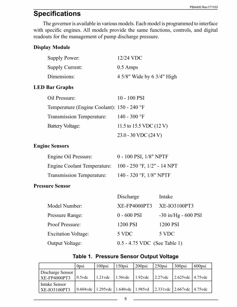
SpecificationsThe governor is available in various models. Each model is programmed to interface
with specific engines. All models provide the same functions, controls, and digital readouts for the management of pump discharge pressure.
Display Module
Supply Power: 12/24 VDC
Supply Current: 0.5 Amps
Dimensions: 4 5/8" Wide by 6 3/4" High
LED Bar Graphs
Oil Pressure: 10 - 100 PSI
Temperature (Engine Coolant): 150 - 240 °F
Transmission Temperature: 140 - 300 °F
Battery Voltage: 11.5 to 15.5 VDC (12 V)
23.0 - 30 VDC (24 V)
Engine Sensors
Engine Oil Pressure: 0 - 100 PSI, 1/8" NPTF
Engine Coolant Temperature: 100 - 250 °F, 1/2" - 14 NPT
Transmission Temperature: 140 - 320 °F, 1/8" NPTF
Pressure Sensor
Discharge Intake
Model Number: XE-FP4000PT3 XE-IO3100PT3
Pressure Range: 0 - 600 PSI -30 in/Hg - 600 PSI
Proof Pressure: 1200 PSI 1200 PSI
Excitation Voltage: 5 VDC 5 VDC
Output Voltage: 0.5 - 4.75 VDC (See Table 1)
Table 1. Pressure Sensor Output Voltage0psi 100psi 150psi 200psi 250psi 300psi 600psi
Discharge SensorXE-FP4000PT3 0.5vdc 1.21vdc 1.56vdc 1.92vdc 2.27vdc 2.625vdc 4.75vdc
Intake SensorXE-IO3100PT3 0.604vdc 1.295vdc 1.640vdc 1.985vd 2.331vdc 2.667vdc 4.75vdc

PBA400 Rev171103
6
GENERAL DESCRIPTIONThe pressure governor is compatible with the following engines:
PBA401 Cummins IS Series
PBA402 Detroit Diesel
PBA404 Navistar
PBA405 Caterpillar
PBA406 Ford
PBA407 Mack
PBA408 Scania
PBA410 Mercedes
PBA416 John Deere
PBA424 MAN
PBA426 IVECO
Components
The information available on the J1939 databus varies depending on the particular engine type. Not all wires are used for all engines. Refer to the engine specific wiring diagram for interface connections. The sensors (if any) that need to be installed also vary depending on the engine.
The governor consist of the following components:
Control Module
Discharge Pressure Sensor
Intake Pressure Sensor
Engine Oil Pressure Sensor (As Necessary)
Engine Coolant Temperature Sensor (As Necessary)
Transmission Temperature Sensor (As Necessary)
Audible Alarm Buzzer (Optional)
Cables

PBA400 Rev171103
7
Control Module
The control module is waterproof and uses 4 5/8 by 6 3/4 inches of panel space. All controls and indicators are located on the front of the control module. (Refer to Controls and Indicators.)
Discharge Pressure Sensor
The pressure sensor is mounted on the pump discharge manifold. It provides an input signal to the control module that is proportional to the pressure.
Intake Pressure Sensor
The pressure sensor is mounted on the pump intake manifold. It provides an input signal to the control module that is proportional to the intake pressure.
Engine Oil Pressure Sensor
The oil pressure sensor is installed as necessary.
Engine Coolant Temperature Sensor
The engine coolant temperature sensor is installed as necessary.
Transmission Temperature Sensor
The transmission fluid temperature sensor is installed as necessary.
Audible Alarm Buzzer (Optional)
The optional buzzer is installed as required. A ground is provided at the 12-pin connector pin 6 to activate the buzzer (max current: 300mA). The buzzer will sound when a fault code becomes activated. (See Table 3 for the Fault Warning Codes list/descriptions on page 15.)
Cables
There are three cables that connect to the control module. The 8-pin connector is for the remote throttle interface, the 12-pin connector is for the discharge sensor, monitoring, and display interface. The 6-pin connector is for the intake pressure sensor, FRC datalink, and the auxiliary interlock.

PBA400 Rev171103
8
Controls and IndicatorsAll controls and indicators are located on the front of the control module. (Refer
to Figure 1.) See Operation and Programming Sections for more information.
MENU Button
Used to access stored data and program features.
Oil Pressure LED Display
Shows engine oil pressure. The LEDs are green when the pressure is within normal limits and red when it is not.
CHECK ENGINE LED, STOP ENGINE LED
Repeats the warnings from the cab.
Engine Temperature LED Display
Shows engine coolant temperature. The LEDs are green when the temperature is within normal limits and red when it is not.
Transmission Temperature LED Display
Shows transmission temperature. The LEDs are green when the temperature is within normal limits and red when it is not.
RPM Display
Shows the current engine RPM in bright red digits. It also shows error codes, stored data, and program features.
Battery Voltage LED Display
Shows battery voltage. The LEDs are green when the voltage is within normal limits and red when it is not.
Day/Night Sensor
Adjusts the brightness of the displays for day or night operations.
SILENCE Button
Press to suppress audio alarms.
Message Display
The message display shows the pressure or RPM setting during normal operations and warning alarms as they occur. It shows the time and date when the throttle ready LED is off. It also shows stored data and program features.
THROTTLE READY LED
This LED is on when the required interlock conditions are met to begin pump operations.

PBA400 Rev171103
9Figure 1. Controls and Indicators
PRESET Button
Press to change/select a pre-programmed value for pressure or RPM setting.
IDLE Button
When pressed immediately sets the engine RPM to idle.
Control Knob
When rotated changes the pressure or RPM setting. The setting increases or decreases proportionally to the speed and direction the control knob is rotated.
RPM Button
Press to select RPM mode. The LED is on to indicate operation in the RPM mode.
PRESSURE Button
Press to select pressure mode. The LED is on to indicate operation in the pressure mode.
RPM Display
Message Display
Day/Night Sensor
Oil Pressure LED Display Engine Temperature
LED Display
Transmission Temperature LED Display
SILENCE Button
MENU Button
Battery VoltageLED Display
Control Knob IDLE Button
THROTTLE READY
LEDPRESSUREMode Button
and LEDRPM
Mode Button and LED
PRESET Button
STOP ENGINE
LED
CHECK ENGINE
LED
PBA400 Rev171103
10
INSTALLATION
Install Control Module1. Measure and mark mounting location for control module panel cutout and
mounting screw holes. Make sure there is clearance behind the panel for the module and cables before cutting holes. Refer to Figure 2 for layout and dimensions.
2. Cut out a 3 1/2 by 5 3/4 inch hole.
3. Drill four holes, clearance or tapped, for 10-32 mounting screws.
4. Place control module in position and secure with screws.
5. Connect cables at rear of the control module. (Refer to Wiring Section.)

PBA400 Rev171103
11Figure 2. Control Module Mounting Dimensions
4 5/8"
6 3/4"
Mounting holes are clearance or tapped for 10-32 screws.
3 1/2"
5 3/4"
Panel Cutout 5 3/4"
4"
Maximum Radius
1/2"
1 1/2"
1 3/4"
2 1/2"4"
PBA400 Rev171103
12
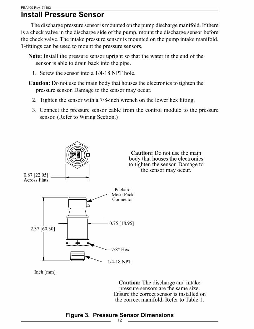
Install Pressure SensorThe discharge pressure sensor is mounted on the pump discharge manifold. If there
is a check valve in the discharge side of the pump, mount the discharge sensor before the check valve. The intake pressure sensor is mounted on the pump intake manifold. T-fittings can be used to mount the pressure sensors.
Note: Install the pressure sensor upright so that the water in the end of the sensor is able to drain back into the pipe.
1. Screw the sensor into a 1/4-18 NPT hole.
Caution: Do not use the main body that houses the electronics to tighten the pressure sensor. Damage to the sensor may occur.
2. Tighten the sensor with a 7/8-inch wrench on the lower hex fitting.
3. Connect the pressure sensor cable from the control module to the pressure sensor. (Refer to Wiring Section.)
Figure 3. Pressure Sensor Dimensions
Caution: Do not use the main body that houses the electronics to tighten the sensor. Damage to
the sensor may occur.
1/4-18 NPT
7/8" Hex
0.75 [18.95]2.37 [60.30]
Inch [mm]
Packard Metri Pack Connector
0.87 [22.05]Across Flats
Caution: The discharge and intake pressure sensors are the same size.
Ensure the correct sensor is installed on the correct manifold. Refer to Table 1.

PBA400 Rev171103
13
Install Engine SensorsFor most engines, the governor receives engine RPM, oil pressure, coolant
temperature, and transmission temperature data over the J1939 databus. Some engines do not broadcast this data over the databus and sensors may need to be installed.
Note: The PumpBoss may need a programming change for some sensor inputs to be recognized. If the sensor was not ordered as part of the PumpBoss kit you may need to contact FRC technical support for programming information.
The sensors are wired to the 12-pin connector at the rear of the control module. Refer to the Wiring Section.
Install BuzzerPin 6 on the 12-pin connector at the rear of the control module is provided to
connect an optional buzzer. Connect the ground side of the buzzer to pin 6. Maximum current through pin 6 is 300 mA. The buzzer ordered from FRC requires a 1-1/8 inch diameter mounting hole. (Refer to the Wiring section.)
Install High Idle KitThe high idle is activated when + VDC is provided to pin 7 (High Idle Active
Input) of the 12-pin connector and pin 6 (Interlock Input) of the 8-pin connector. Refer to High Idle Wiring.
Note: It is important that the connection to the Interlock Input from the High Idle circuit be isolated from the apparatus interlock wiring with the two diodes. The pump must NOT be engaged when using the high idle function and the THROTTLE READY LED will be off.
Install Remote Governor OptionRefer to Install Control Module for dimensions. The remote governor is connected
to power, the J1939 CAN Bus, and the FRC datalink. Refer to Wiring Section.
Note: Program code P303 SYS TYPE must be set to REMOTE in the remote governor program.

PBA400 Rev171103
14
OPERATIONNote: When power is applied to the governor the message display shows the
Software Program Revision Number for five (5) seconds. It can also be viewed with P101 code, refer to Programming Section.
On power-up the governor is in the pressure mode of operating. The RPM display shows engine RPM, the four LED bar graphs are green indicating readings within normal ranges, and the message display alternates between showing the date and time.
If a monitored function is not within normal parameters the display flashes, the RPM display shows an error or fault warning code and a description shows in the message display. (Refer to Table 2. Error Codes or Table 3. Fault Warning Codes.)
If one of the inputs displayed by the LED bar graphs is not within normal range the LEDs will be red.
When all necessary throttle enables are active and the interlock circuit is complete, the THROTTLE READY LED comes on and the governor is ready to control the engine RPM. The control signal is set at idle regardless of the control knob position.
ControlsControl Knob
The control knob is used to adjust pressure and RPM settings. The governor senses how fast and in what direction the control knob is rotated and sends a signal to the ECM to increase or decrease the engine RPM proportionally.
If the control knob is rotated quickly; the engine RPM changes quickly.
If the control knob is rotated slowly; the engine RPM changes slowly.
• Rotate the control knob clockwise* to increase engine RPM.
• Rotate the control knob counterclockwise* to decrease engine RPM.
• Press the red IDLE button to immediately return the engine to idle.
*NOTE: Opposite knob rotation option is available to increase/decrease the engine RPM.

PBA400 Rev171103
15
Table 2. Error Codes
Table 3. Fault Warning CodesRPM
DisplayMessage Display Description Factory
Default SettingF01 HI BATT VOLTAGE High Battery Voltage 15.5 VF02 LOW BATT VOLTAGE Low Battery Voltage 11.8 V*F03 HI TRANS TEMP High Transmission Temperature 300 °FF04 LOW OIL PRESSURE Low Engine Oil Pressure 8 PSI**F05 DPFR Discharge Sensor High VoltageF06 IPFR Intake Sensor High VoltageF07 HI ENG TEMP High Engine Coolant Temperature 220 °F**F08 NO WATER Out of Water ModeF09 ENG NOT RESPOND Engine Does Not Respond
* 11.8 engine running, 11.7 engine off.
Error Codes and Fault Warnings
RPM Display
Message Display
Probable CauseNote: Not all inputs are used for all engines.
E01 NO DATA >J1939 CAN bus cable not connected / connected to wrong port>Broken wire / bad connector contact on cable
E02 NO RPM Engine RPM not detected>Data cable not connected / connected to wrong port>Engine not running / ignition key on>Broken wire / bad connector contact on alternator cable
E04 NO OIL SENSOR
No Engine Oil Pressure Data Detected (w/separate sensor input)>Sensor cable not connected>Broken wire / bad connector contact on sensor cable>Defective pressure sensor
E05 NO D. PSR SENSOR
No Discharge Pressure Sensor Detected>Sensor cable not connected>Broken wire / bad connector contact on sensor cable>Defective pressure sensor
E06 NO I. PSR SENSOR
No Intake Pressure Sensor Detected>Sensor cable not connected>Broken wire / bad connector contact on sensor cable>Defective pressure sensor
E07 NO ENG T SENSOR
No Coolant Temperature Data Detected (w/separate sensor input)>Sensor cable not connected>Broken wire / bad connector contact on sensor cable>Defective temperature sensor
E16 NO FRC DATALINK
>FRC datalink cable not connected / connected to wrong port>Broken wire / bad connector contact on cable
Note: E5 and E6 show on a remote governor not programmed correctly (code P303).
** J1939 compliant—engine ECM will issue this warning.

PBA400 Rev171103
16
Pressure Mode OperationIn the pressure mode of operation the PRESSURE LED is on. The governor
maintains a constant discharge pressure within system capabilities. It adjusts the engine RPM automatically to compensate for variations in pressure.
There is a maximum engine RPM programmed in the governor for pressure mode. If the engine reaches the programmed maximum RPM the message display flashes MAX RPM / OPERATOR and the engine RPM is not allowed to go higher. (The maximum engine RPM is normally set at 2100 and is programmable.)
If the discharge pressure is below 15 PSI when the operator increases the pressure setting, the display shows PRESS LOW.
Note: When changing from RPM to pressure mode during operations, hold the PRESSURE button for 3 seconds. The pressure setting is the pressure that the pump was operating at in RPM mode.
1. Press PRESSURE button to select the pressure mode.
Result: PRESSURE LED goes on.
2. Press PRESET and/or rotate control knob to select pressure setting.
Result: Message display shows pressure setting, engine RPM changes.
3. Press IDLE button after operations to set engine to idle RPM.
Result: Message display shows IDLE ENGINE, engine at idle RPM.
Opening/Closing Discharge Valves
In pressure mode the governor maintains the pressure setting regardless of the number of discharge lines that are opened or closed providing there is sufficient water supplied. As lines are opened the discharge pressure starts to drop and the governor raises the engine RPM to maintain the required pressure. As lines are closed and the discharge pressure starts to rise, the governor lowers the engine RPM to maintain the required pressure.
Operating From a Pressurized Supply
When operating from a pressurized water source (hydrant, in-relay, etc.), the intake supply should be routed through a valve. If the pressurized source fails, the pump operator can close the valve. This eliminates the chance of sharp pressure spikes at the pump intake if the supply is resumed suddenly. The operator must open this valve slowly when the supply is resumed to help prevent pressure spikes.

PBA400 Rev171103
17
Running Away From Water, Low Water, or No Supply Water
There are situations during pump operations when there may be low or no supply water. This can be due to an empty water tank, a problem on the intake line, air in the pump, changing the water source, or an insufficient water supply.
The governor constantly monitors discharge pressure and compares it to engine RPM. It is programmed to limit RPM increases when conditions arise that fall outside of normal operating parameters.
Running Away From Water: If the discharge pressure starts dropping while operating in pressure mode, the governor increases the engine RPM and attempts to maintain the selected pressure setting. If pressure drops and an increase in RPM does not bring the pressure back up, the governor recognizes this as a running away from water condition. When this condition occurs the governor switches to the RPM limit mode and controls the engine RPM accordingly.
RPM Limit Mode: When the RPM limit mode is in effect the PRESSURE LED stays on. To alert the operator the RPM LED and the RPM display flash, and the message display flashes OPERATOR / RPM LIMIT. In this mode the pressure setting does not change and the PRESET button is disabled. When the pressure comes back up to the selected pressure setting, the RPM limit mode is canceled and the governor switches to normal operation in pressure mode at the selected pressure.
In some cases the pressure may not come back up but remains at a level above 45 PSI. In the RPM limit mode, the governor behaves like a manual throttle and the operator can raise or lower the engine RPM by rotating the control knob. If the RPM is manually lowered to a point where the pump is not running away from water and pressure is stable, the RPM limit mode is canceled. The governor switches to normal operation in pressure mode with the current discharge pressure as the new pressure setting.
If the engine is set to idle using the IDLE button, the governor comes out of RPM Limit Mode and cancels the pressure setting.
Low Water Cycle: If the discharge pressure is below 45 PSI, but stays above 15 PSI, the governor enters a low water cycle and the message display flashes LO WATER. It sets the engine at 1100 RPM. If the pressure does not rise above 45 PSI in 7 seconds, the governor sets the engine RPM at idle. The governor repeats the low water cycle as long as the discharge pressure is between 15 and 45 PSI. When the pressure rises above 45 PSI the governor resumes normal operation. (The values for RPM and PSI in the low water cycle are programmable and may vary for some engine/pump combinations.)
No Supply Water: If the discharge pressure is below 15 PSI, the engine RPM is set at idle and the message display flashes NO WATER. If, within 3 minutes, the discharge pressure rises above 15 PSI the governor enters the low water cycle. If the discharge pressure does not rise above 15 PSI within 3 minutes, the governor switches to idle mode and cancels the pressure setting. To restart pump operations, the operator must take action (press PRESET and/or rotate control knob to select pressure setting).
PBA400 Rev171103
18
RPM Mode OperationIn the RPM mode of operation the RPM LED is on. The governor maintains a
constant engine RPM.The pump discharge pressure can vary but, as a safety feature, the governor limits
the increase in pressure to 30 PSI over the last established PSI value. As the discharge pressure approaches this limit the governor automatically lowers the RPM to prevent a high pressure surge. The RPM LED blinks as the governor sets a lower RPM. This lower RPM will be the new operating RPM setting.
Note: When changing from pressure to RPM mode during operations, hold the RPM button for 3 seconds. The RPM setting is the RPM that the pump was operating at in pressure mode.
1. Press RPM button to select RPM mode.
Result: RPM LED goes on.
2. Press PRESET and/or rotate control knob to select RPM setting.
Result: Message display shows RPM setting, engine RPM changes.
3. Press IDLE button after operations to bring engine to idle RPM.
Result: Message display shows IDLE ENGINE, engine at idle RPM.
PBA400 Rev171103
19
Switching Between Operating Modes• No variation in discharge pressure or RPM occurs when changing between
pressure and RPM modes.
• When changing to RPM mode, the RPM setting is the RPM that the pump was operating at in pressure mode.
• When changing to pressure mode the pressure setting is the pressure that the pump was operating at in RPM mode.
When the engine is at idle RPM:
Press the mode button and the governor changes modes immediately.
When the engine RPM is above idle:
Press and hold the mode button for 3 seconds and the governor changes modes. (This is to avoid an accidental change over if the buttons get bumped.)
Pump Discharge Pressure is High at Engine IdleOnce the governor has set the engine RPM at idle, it can do no more to reduce
discharge pressures. To reduce discharge pressure the pump operator can gate incoming water, reduce pressure at the intake relief valve, gate discharges, or disable the pump.
RPM Limit with Discharge Pressure Less than 100 PSIThe level II programming code P221 sets the maximum RPM when the pump is
operating with a discharge pressure less than 100 PSI. The factory set default is for code P221 is 1500. Access to level II programming required a password. Contact FRC if this default limit needs to be changed.
Remote Governor OptionThe remote governor option duplicates the primary governor functions.The remote governor control module is required to be programmed as a remote
(program code P303). If error codes E5 and E6 show on power up, check the programming.
PBA400 Rev171103
20
Detailed InformationThe four LED bar graphs provide constant display of safe operating ranges for
engine oil pressure, engine coolant temperature, transmission temperature, and battery voltage. They do not show exact numbers or units of measure. Detailed information is shown in the message display when the MENU button is pressed. Engine hours and pump hours are also shown.
Show Detailed Information
Note: Detailed information is a display only mode and no changes can be made to the data.
The MENU button allows the operator to gain access to detailed information. Each time the MENU button is pressed the display scrolls to show the next value.
The message display indicates the following:
ENG TEMP ### °F (programmable for °C)
ENG OIL ### PSI (programmable for kPa or Bar)
BATT VDC ##.# V (programmable for 12V or 24V)
ENG HRS ####
PUMP HRS ####
TRANS T. ### °F (programmable for °C)
D.SENSOR #### PSI (programmable for kPa or Bar)
I.SENSOR #### PSI (programmable for kPa or Bar)The message display reverts to normal operation after 20 seconds if no buttons are
pressed. When a button other than the MENU button is pressed, the display immediately reverts to normal operation. The SILENCE button should be used during operations.
High-IdleThe governor programming includes a high-idle function. To activate the high-idle
set all interlocks as called for by local SOP (normally this would include the transmission in neutral and the parking brake on). Set the High-Idle switch to ON.
Note: The pump must NOT be engaged when using the high-idle function and the THROTTLE READY LED will be off.
Change High-Idle Setting
Note: The high-idle is set at about 1000 RPM at the factory. (This value varies depending on the specific engine.)
1. With the engine running, set the high-idle switch to ON.
Result: Engine goes to high idle RPM.
PBA400 Rev171103
21
Preset Settings (Pressure or RPM)The preset button allows the operator to go to a pre-programmed pressure or
RPM setting during operations. The preset value shows in the message display. This procedure is to change the pre-programmed setting. (Factory default preset maximum limits are: pressure = 200 PSI; RPM = 1500.)
Note: The engine must be running and the pump engaged interlock circuit must be closed (the THROTTLE READY LED must be on).
1. Press IDLE button.
Result: Engine goes to idle RPM
2. Press PRESSURE or RPM button to select the setting to be changed.
Result: LED indicator goes on for mode selected.
Note: The message display must show IDLE ENGINE before changing the preset.
3. Press and hold PRESET button. (Continue to hold through step 4.)
Result: Message display shows PRESET. After 5 seconds the current setting flashes. The preset value is set at this time but is not allowed to exceed the factory default limits of pressure = 200; RPM = 1500.
Note: If the factory default limits are to be exceeded, step 3a. must be included, if not proceed with step 4.3a. Press and hold the SILENCE button for 5 seconds to unlock the default limits.
Result: Message display shows UNLOCKED. Release the SILENCE button (continue to hold the PRESET button). The preset value is now allowed to exceed the default limit.
4. Rotate control knob to change preset setting.
5. Release PRESET button.
Result: The new preset value is programmed. Message display shows IDLE ENGINE.
2. Press and hold PRESET button for 3 seconds.
Result: RPM display flashes and shows the high-idle setting.
3. Keep pressing the PRESET button and rotate control knob to desired RPM.
4. Release PRESET button to store the new high idle setting.

PBA400 Rev171103
22
PROGRAMMINGThe following program functions are always available to view and change:P101 - Software Program Revision Number - Read OnlyP102 - Product Manufacturing Date - Read OnlyP103 - Set Current Date - Read/WriteP104 - Set Current Time - Read/WriteP105 - Retrieve Fault Codes - Read OnlyP106 - Engine Type Code - Read Only
Access Program Features
Note: When the program (P) code is flashing in the RPM display, press the PRESSURE or RPM button to scroll through the P-codes or press the SILENCE button to exit the programming mode.
1. Press the SILENCE button and hold it until the RPM display shows four dashes – – – – and the message display shows ENTER--- CODE. Release the button.
Result: P 1 0 1 flashes in the RPM display. The message display shows the program revision number PROG REV V500.03.
2. Press the PRESSURE button.
Result: P 1 0 2 flashes in the RPM display. The message display shows the manufacturing date MFG DATE 16JAN'15 (ddmmm'yy).
3. Press the PRESSURE button.
Result: P 1 0 3 flashes in the RPM display. The message display shows the current date SET DATE 16JAN'15.
4. To Change the Date: (If not, go to step 5.)
a. Press the MENU button.
Result: P 1 0 3 stops flashing. The message display shows the current date with the year flashing.
b. Press the PRESSURE or RPM button to change the year.
c. Press the MENU button.
Result: The month flashes.
d. Press the PRESSURE or RPM button to change the month.
e. Press the MENU button.
Result: The day flashes.
f. Press the PRESSURE or RPM button to change the day.
g. Press and hold the SILENCE button to store the new date.
Result: P 1 0 4 flashes in the RPM display. The message display shows SET TIME 10:30AM . Go to step 6.

PBA400 Rev171103
23
5. Press the PRESSURE button.
Result: P 1 0 4 flashes in the RPM display. The message display shows SET TIME 10:30AM .
6. To Change the Time: (If not, go to step 7.)
a. Press the MENU button.
Result: P 1 0 4 stops flashing. The message display shows the current time with the AM or PM flashing.
b. Press the PRESSURE or RPM button to change AM or PM.
c. Press the MENU button.
Result: The minute flashes.
d. Press the PRESSURE or RPM button to change the minutes.
e. Press the MENU button.
Result: The hour flashes.
f. Press the PRESSURE or RPM button to change the hours.
g. Press and hold the SILENCE button to store new time.
Result: P 1 0 5 flashes in the RPM display. The message display shows NO WARNING or LOGGED DATA. Go to step 8.
7. Press the PRESSURE button.
Result: P 1 0 5 flashes in the RPM display. The message display shows NO WARNING or LOGGED DATA.
8. Press the MENU button when it shows LOGGED DATA or go to step 9.
Result: 5 1 flashes in the RPM display. The fault, date, and time that the fault code was recorded shows in the message display.
a. To scroll through the logged fault code data, press the PRESSURE or RPM button.
b. Press the SILENCE button to exit viewing logged data.
9. Press the PRESSURE button.
Result: P 1 0 6 flashes in the RPM display. The message display shows the engine type code that is set in the program. (Refer to the Engine Code Reference Table, Document Number XE-ECRTREF01-R0A.)
10 Press the PRESSURE or RPM button to scroll through the P-codes or press the SILENCE button to exit the programming mode.

PBA400 Rev171103
24
Access Password Protected ProgramsThe following program functions are available to view and change after the
password code has been entered:
Calibration Password Code 1111
C1 - Discharge Pressure Sensor Zero Calibration
C2 - Intake Pressure Sensor Zero Calibration
C3 - Engine RPM CalibrationRefer to Calibration Section.
Operator Password Code 1221
Operator Password Code 1221 allows the parameter settings of limited program functions to be changed. Refer to Table 4. Operator Password Protected Program Functions.
P318 - RPM Limit for Pressure Control (Factory default is 2100.)
Enter Password Code
Note: To exit the programming mode, press the SILENCE button when the program code flashes in the RPM display.
1. Press the SILENCE button and hold it until the RPM display shows four dashes – – – – and the message display shows ENTER--- CODE. Release the button.
2. Press the MENU button within three seconds. The message display shows CODE ENTRY. The RPM display shows the number 1000. Each time the MENU button is pressed the first digit increments by 1. Set the first digit to the desired number.
3. Press the SILENCE button to move the curser to the next digit. Press the MENU button to change the digit.
4. Repeat step 3 and enter the password code. (Calibration password is 1111. Operator password is 1221.)
Result: When a correct password code is entered C 1 for calibration or P 3 1 8 flashes in the RPM display.
5. Press the PRESSURE or RPM button when the program code is flashing to scroll through the program codes.
PBA400 Rev171103
25
6. Press the MENU button to enter the programming mode to view and change parameter settings.
Result: The program code stops flashing. The message display shows a selectable option or a numerical value.
7. Press the MENU button to change a selectable option or the PRESSURE or RPM button to change a numerical value.
8. Press the SILENCE button to save the changes and exit the programming mode.
Result: The program code advances to the next code and flashes.
9. Repeat steps 5 through 8 as necessary.
10. Press the SILENCE button when the program code is flashing to exit.
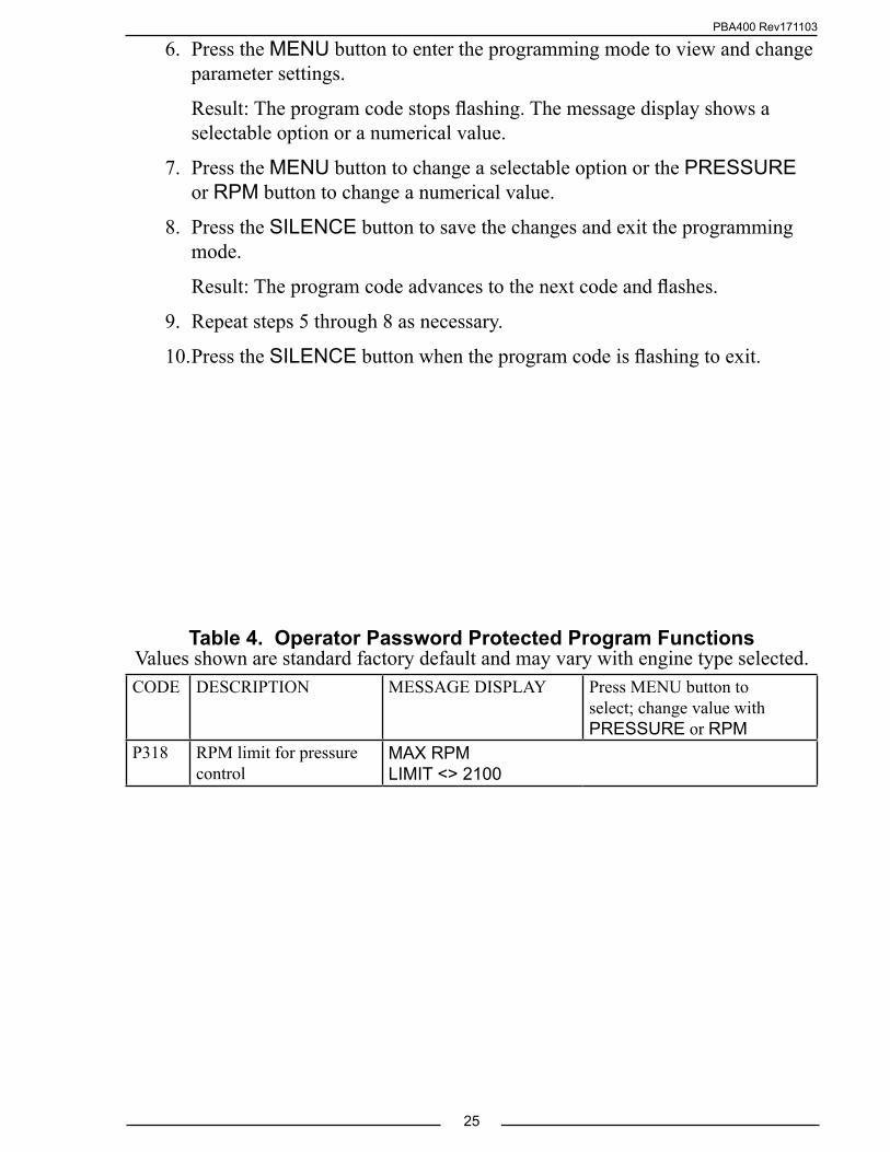
CODE DESCRIPTION MESSAGE DISPLAY Press MENU button to select; change value with PRESSURE or RPM
P318 RPM limit for pressure control
MAX RPMLIMIT <> 2100
Table 4. Operator Password Protected Program FunctionsValues shown are standard factory default and may vary with engine type selected.

PBA400 Rev171103
26
CODE DESCRIPTION MESSAGE DISPLAY
Press MENU Button Again
Press MENU Button Again
C1 Discharge Pressure Sensor Zero Calibration
D.PSI D.PSISET P=0?
D.PSID.PSI=0
C2 Intake Pressure Sensor Zero Calibration
I.PSI I.PSISET P=0?
I.PSII.PSI=0
C3 Engine RPM Calibration CAL.ENG RPM
SET RPMXXXX
Table 5. Calibration Codes Quick Reference Chart
CALIBRATIONThree programs are available after the calibration password code has been entered:
C1 - Discharge Pressure Sensor Zero Calibration
C2 - Intake Pressure Sensor Zero Calibration
C3 - Engine RPM CalibrationRefer to Table 5. Calibration Codes Quick Reference Chart.
Enter Calibration Password Code 1111
Note: To exit the programming mode, press the SILENCE button when the program code flashes in the RPM display.
1. Enter the password code 1111. (Refer to Programming Section.)
Result: When the correct password code is entered C 1 flashes in the RPM display. The message display shows D.PSI.
2. Press the PRESSURE or RPM buttons when the program (C) code is flashing to scroll through the program codes.
Refer to specific calibration section for detailed procedures.
Note: If there is a failure during calibration the message display shows SENSOR PROBLEM.
3. Press the SILENCE button when the program (C) code is flashing to exit.

PBA400 Rev171103
27
Pump Pressure Sensor (Code C1 and C2)The program for the pump pressure sensor(s) is self-calibrating. There are no
adjustments that can be made to the sensors. When the calibration program is activated the signal from the sensor(s) is assumed to be 0 PSI.
Note: If there is pressure in the plumbing where the sensor is mounted this causes the program to be calibrated to a false 0. To prevent false zeroing, drain the pump and plumbing to ensure there is no residual pressure before running the calibration procedure.
1. Apply power to the display module.
2. Enter the calibration password.
3. Scroll to code C1 D.PSI or C2 I.PSI.
4. Press the MENU button SET P=0? flashes.
5. Press the MENU button again to set at 0. D.PSI=0 or I.PSI=0 flashes.
6. Press and hold the SILENCE button for 3 seconds to save the setting into memory.
7. Press the SILENCE button when the program (C) code is flashing to exit calibration. Press the MENU button to enter the next program. Press the PRESSURE or RPM buttons to scroll through program codes.
Engine RPM (Code C3)This code is not applicable for engines with the J1939 CAN connected. To perform
the following calibration, a reference tachometer is needed to verify the correct engine RPM.
1. Apply power to the display module.
2. Enter the calibration password.
3. Scroll to code C3 CAL. ENG RPM.
4. Press the MENU button to show SET RPM.
Result: Flashing digit is ready to be changed.
5. Set the RPM to match the reference RPM. Press the PRESSURE or RPM buttons to change the value. Press the MENU button to change the digit.
6. Press the SILENCE button to save the setting into memory.
7. Press the SILENCE button when the program (C) code is flashing to exit calibration. Press the MENU button to enter the next program. Press the PRESSURE or RPM buttons to scroll through program codes.

PBA400 Rev171103
28
Notes:- Not all wires are used for all engines. Refer to the engine specific wiring diagram for interface connections.- An adapter and cable assembly replaces the basic 8-pin cable when connecting the governor to a GMC engine. Refer to the engine specific wiring diagram.
Notes:- Not all wires are used for all engines.- High idle is not available for GMC.- When using an FRC provided engine sensor cable, the red wire is sensor signal and the black wire connects to a ground.
Figure 4. PBA Connectors
WIRINGThe following figures include the schematics, wiring diagrams, block diagrams,
and cables for the governor.
Connectors and CablesFor most engines the governor receives engine RPM, oil pressure, and coolant
temperature data over the J1939 data link from the ECM. Some engines do not broadcast this data over the data link and sensors may need to be installed.
When a remote governor is installed ensure that the control module program code P303 is set to REMOTE. Refer to Figure 5 for wiring details.
12 Pin Connector/CablePin Wire Color Description 1 Red + 5 VDC Discharge Pressure Sensor2 Black Ground Discharge Pressure Sensor3 White Signal Discharge Pressure Sensor4 Blue Engine Oil Press. Sensor Signal5 Orange Engine Temp. Sensor Signal6 Brown Buzzer Ground (300mA)7 Violet High Idle Active Input (+ VDC)8 White J1939 CAN (Shield)9 Black J1939 CAN (–)10 Red J1939 CAN (+)11 Green Transmission Temp. Sensor Signal12 Yellow RPM Signal
8 Pin Connector/CablePin Wire Color Description 1 Red Supply Power (12/24 VDC)2 Black Ground3 Orange +5 VDC Reference From ECM4 White Throttle Signal To ECM 5 Green Signal Return From ECM6 Yellow Interlock Input (+ VDC)7 Blue Throttle Enable Signal Output8 Brown Foot Pedal Signal Input
Control Module Rear View8-Pin
Connector Pin 1
12-Pin Connector
Pin 1
6-Pin Connector
Pin 1
USBAccess Port*
Vent
*NOTE: If opened, USB access port plug must be tightened to a torque of 8-10 in-lbs. Exceeding this torque value can result in damage to its water seal capability. Warning: Flange may not fully bottom out.

PBA400 Rev171103
29Figure 5. PBA Connector Wiring
Notes:- Pump intake sensor on PBA400 only.
6 Pin Connector/CablePin Wire Color Description 1 Red + 5 VDC Intake Pressure Sensor2 Black Ground Intake Pressure Sensor3 White Signal Intake Pressure Sensor4 Green FRC Datalink (–)5 Yellow FRC Datalink (+)6 N/C
12-Pin Connector
Note: The program code P303 must be set to REMOTE on the Secondary Controller control module.
To J1939(See Engine Specific Wiring)
Secondary Controller12, 8 and 6 Pin Connector Wiring
+12 VDC
GND
Ignition Key
RED
BLK
8-Pin Connector
NOTE: Terminating resistor and adapters are included in the kit for connection to the primary display; no other wires are required for remote operation.
6-Pin Connector
YELGRN
FRC Datalink (+)FRC Datalink (–)
To the Primary Controller
Data Bus Terminator
6-Pin Connector
YELGRN
FRC Datalink (+)FRC Datalink (–)
To the Secondary Controller
Data Bus TerminatorTo Intake Pressure Sensor
GRN
Secondary Controller, Cables and Connections

PBA400 Rev171103
30Figure 6. Pressure Sensor Wiring
Pressure Sensor Side View
Pressure Sensor Cable 3-Pin Connector
Pin/Wire DescriptionA/Black GroundB/Red Supply VoltageC/White Signal
Pressure Sensor
Pressure SensorTop View
Pressure Sensor Cable
Caution: The discharge and intake pressure sensors are the same size.
Ensure the correct sensor is installed on the correct manifold. Refer to Table 1.
Signal Output
Supply Voltage
Ground

PBA400 Rev171103
31Figure 7. Common OEM 9-Pin Diagnostic Connector
Common OEM Diagnostic Connector
Typical 9-pin Deutsch Diagnostic Connector.Commonly found under the driver side dashboard.
9-Pin ConnectorPin Description A BATTERY GROUND B +12 VDC C J1939 CAN (+) D J1939 CAN (–) E J1939 SHIELD F J1587 DATA BUS (+) G J1587 DATA BUS (–) H PLUG J PLUG
FRONT VIEW
BF
E
A
C
D
GH
J

PBA400 Rev171103
32Figure 8. Cummins PBA401 Wiring
Cummins Harness ConnectionsInterface Information
For use on 2004 or newer engines.The governor is designed to control engine throttle directly over the SAE J1939
databus.If the PUMPBOSS is being used on a COMMERCIAL CHASSIS with a Cummins
Engine, ENSURE that the Cummins Engine EMERGENCY VEHICLE CALIBRATION is programmed in the engine ECM for the PUMPBOSS to work.
Note: Refer to Figure 4. PBA Connector Wiring for power and interlock wire connections.
1817
J1939 Datalink (–)Pin 9 Black WirePin 10 Red Wire J1939 Datalink (+)
12-Pin Connector (Refer to Figure 4)
ECM OEM Connector
2010ISC8.3/CM2250/ISL9
Model Engines
4622
J1939 Datalink (–)Pin 9 Black WirePin 10 Red Wire J1939 Datalink (+)
12-Pin Connector (Refer to Figure 4)
ECM OEM Connector
2013CM2350
Model Engines

PBA400 Rev171103
33Figure 9. Detroit Diesel PBA402 Wiring
Detroit Diesel Harness ConnectionsInterface Information.
The governor is designed to control engine throttle directly over the SAE J1939 databus. Remote throttle does not need to be enabled in the ECM.
Note: Refer to Figure 4. PBA Connector Wiring for power and interlock connections.
ECU
J1939 CAN (–)
J1939 SHIELD
J1939 CAN (+)
2/16
2/17
2/18
DDECVI
12-Pin Connector (Refer to Figure 4)
Vehicle Interface Harness 18-Pin Connector #2
For DDEC VI 2007 and Newer Engines
Pin 9 Black Wire
Pin 8 White Wire
Pin 10 Red Wire
ECU
J1939 CAN (+)
Shield
J1939 CAN (–)
V-43
V-44
V-58
Dk Blu/Red
Dk Blu/Yel
Dk Blu
DDEC V
12-Pin Connector (Refer to Figure 4)
Vehicle Interface Harness Connector
For DDEC V 2003 to 2006 Engines.
Pin 10 Red Wire
Pin 9 Black Wire
Pin 8 White Wire
PBA400 Rev171103
34
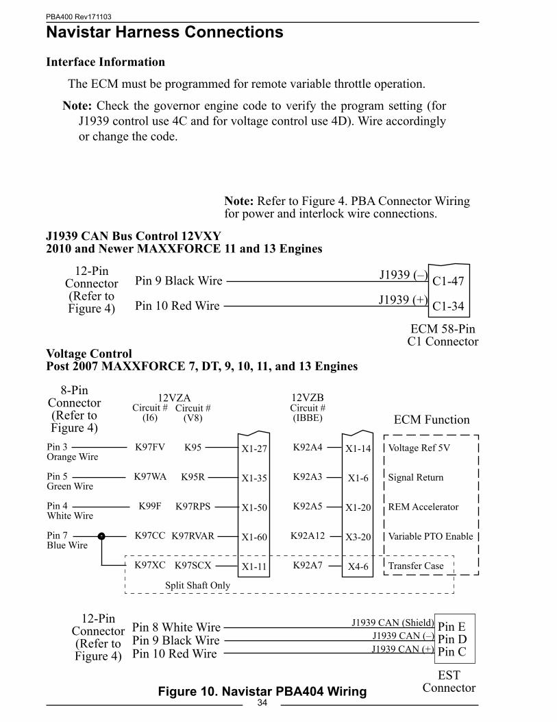
Navistar Harness ConnectionsInterface Information
The ECM must be programmed for remote variable throttle operation.
Note: Check the governor engine code to verify the program setting (for J1939 control use 4C and for voltage control use 4D). Wire accordingly or change the code.
Figure 10. Navistar PBA404 WiringEST
Connector
J1939 CAN (–)J1939 CAN (Shield)
Pin 9 Black WirePin 8 White Wire
Pin 10 Red Wire J1939 CAN (+)
Pin EPin DPin C
12-Pin Connector (Refer to Figure 4)
Note: Refer to Figure 4. PBA Connector Wiring for power and interlock wire connections.
Voltage ControlPost 2007 MAXXFORCE 7, DT, 9, 10, 11, and 13 Engines
8-Pin Connector (Refer to Figure 4)
Split Shaft Only
ECM Function
Voltage Ref 5V
Signal Return
REM Accelerator
Variable PTO Enable
Transfer Case
Circuit #(V8)
K95
K95R
K97RPS
K97RVAR
K97SCX
Circuit #(IBBE)
K92A4
K92A3
K92A5
K92A12
K92A7
Pin 3Orange Wire
Pin 5Green Wire
Pin 4White Wire
Pin 7Blue Wire
X1-27
X1-35
X1-50
X1-60
X1-11
X1-14
X1-6
X1-20
X3-20
X4-6
Circuit #(I6)
K97FV
K97WA
K99F
K97CC
K97XC
J1939 CAN Bus Control 12VXY2010 and Newer MAXXFORCE 11 and 13 Engines
C1-47
C1-34
J1939 (–)
J1939 (+)Pin 9 Black Wire
Pin 10 Red Wire
12-Pin Connector (Refer to Figure 4)
ECM 58-PinC1 Connector
12VZA 12VZB

PBA400 Rev171103
35Figure 11. Navistar/International Chassis PBA404 Wiring
Navistar / International Chassis Harness ConnectionsInterface Information
Note: This function is not available on custom chassis, refer to Figure 10. Navistar PBA Wiring.
Vehicles must be equipped with an Electronic System Controller (ESC) and have the Body Builder J1939 Datalink available.
Remote Engine Speed must be set to ON (Feature Code 0595AHA)Connect the Body Builder J1939 Datalink to the FRC Datalink for engine control
as shown below.
ATA Datalink
ConnectorJ1939 CAN (Shield)
J1939 CAN (–)
J1939 CAN (+)
Pin 8 White Wire
Pin 9 Black Wire
Pin 10 Red Wire
Pin E
Pin D
Pin C
12-Pin Connector (Refer to Figure 4)
Note: Refer to Figure 4. PBA Connector Wiring for power and interlock wire connections.
Body Builder J1939 Datalink (–)
Body Builder J1939 Datalink (+)
FRC Datalink (–)
FRC Datalink (+)
F5
F6
6-Pin Connector (Refer to Figure 4)
1602(ESC J5)
Connector
Pin 4 Green Wire
Pin 5 Yellow Wire
Note: The Body Builder J1939 Datalink is for engine control, the J1939 CAN Bus provides
engine information to the governor.
Engine Control Output
Engine Information Input
PBA400 Rev171103
36
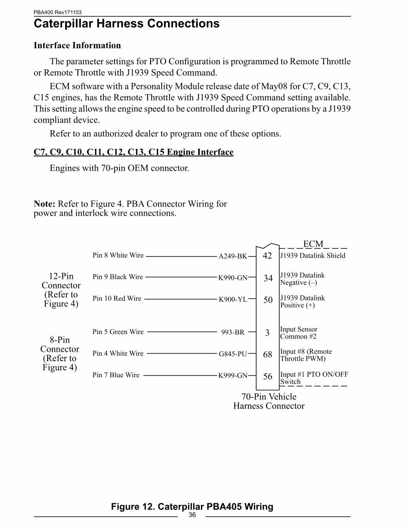
Caterpillar Harness ConnectionsInterface Information
The parameter settings for PTO Configuration is programmed to Remote Throttle or Remote Throttle with J1939 Speed Command.
ECM software with a Personality Module release date of May08 for C7, C9, C13, C15 engines, has the Remote Throttle with J1939 Speed Command setting available. This setting allows the engine speed to be controlled during PTO operations by a J1939 compliant device.
Refer to an authorized dealer to program one of these options.
C7, C9, C10, C11, C12, C13, C15 Engine Interface
Engines with 70-pin OEM connector.
Note: Refer to Figure 4. PBA Connector Wiring for power and interlock wire connections.
Figure 12. Caterpillar PBA405 Wiring
12-Pin Connector (Refer to Figure 4)
8-Pin Connector (Refer to Figure 4)
J1939 Datalink Negative (–)
J1939 Datalink Shield
J1939 Datalink Positive (+)
993-BR
G845-PU
K999-GN
Input Sensor Common #2
Input #1 PTO ON/OFF Switch
Input #8 (Remote Throttle PWM)
ECM
70-Pin Vehicle Harness Connector
3
68
56
34
42
50
Pin 5 Green Wire
Pin 4 White Wire
Pin 7 Blue Wire
Pin 8 White Wire
Pin 9 Black Wire
Pin 10 Red Wire
A249-BK
K990-GN
K900-YL
PBA400 Rev171103
37
Ford Harness ConnectionsJ1939 Interface Information
A J1939 CAN input is required to provide engine information to the governor. The Ford vehicle CAN Bus information needs to be interpreted. A J1939 Translator Module with a harness to connect it to the ODB-II connector must be installed.
Note: The ODB-II connector and wiring is accessed under the dash.There are two scenarios:
I. The J1939 Translator Module is installed as a component with governor kit (no Seat Belt Monitoring System is installed).
Install the J1939 Translator Module and the ODB-II interconnecting harness (provided with the governor kit). A 2-Pin connector is provided for the wires to governor.
II. The J1939 Translator Module is installed as part of the NFPA1901 compliant Seat Belt Monitoring and VDR System.
The Translator Module/ODB-II/VDR harness is under the driver side dash. A T-cable (provided with the governor kit) needs to be installed at the 4-Pin connector that is between the harness and the VDR.
Stationary Elevated Idle Control (SEIC) Interface Information
Note: Access wires for SEIC are located in cabin, tagged and bundled above the parking brake pedal assembly behind datalink connector.
SEIC is used in two modes: stationary and split shaft. The governor provides a variable RPM control to the Ford Power train Control Module (PCM) when all enabling conditions are met. Refer to Figure 14 Ford PBA PCM Wiring.
SEIC Enablers: Parking brake applied; Foot off of service brake; Vehicle in park; Foot off of accelerator pedal; Vehicle speed is 0 mph (stationary); Engine at a stable base idle speed.
Note: Do not press the accelerator or service brake pedal when engaging the fire pump, this prevents the switch into SEIC.

PBA400 Rev171103
38
Translator Module Harness
(2-Pin Connector)
J1939 (+)
J1939 (–)Pin 10 Red Wire
Pin 9 Black Wire
PBA406 12-Pin
Connector (Refer to Figure 4)
Figure 13. Ford PBA406 J1939 Translator Module Wiring
Mounting holes are clearance for #8 screws.
Install the J1939 Translator Module with the ODB-II Interconnecting Harness or Install the T-cable between 4-Pin connectors.
To install the J1939 Translator Module with ODB-II harness, read and follow the installation instructions provided with the Translator Module kit.
J1939 Translator Module
2"
4"3 1/2"
1"
J1 Connector
TEST Pad
Disconnect VDR harness 4-Pin connector and connect the T-cable
provided with the governor kit.
J1939 Translator Module and VDR Harness
To OEM ODB-II
Connector
Pass Through ODB-II
Connector
To Translator Module J1 Connector
To FRC VDR 8-Pin Connector
2-Pin Connector1-Red J1939 (+)2-Blk J1939 (–)
4-Pin VDR Connector
To Governor12-Pin Connector
Note: The TEST pad on the module circuit board has to be held at ground when the harness connector is plugged into the J1 connector.
To OEM ODB-II
Connector
To Translator Module J1 Connector
Pass Through ODB-II
Connector
2-Pin Connector1-Red J1939 (+)2-Blk J1939 (–)
To Governor12-Pin Connector
J1939 Translator Module Harness
Translator Module Harness to Governor
Note: Refer to Figure 4. PBA Connector Wiring for governor power and interlock wire connections.

PBA400 Rev171103
39Figure 14. Ford PBA406 PCM Wiring
2011 Model F-250/350/450/550 - 6.7L Diesel EngineStationary Elevated Idle Control (SEIC)
Note: Do not press the accelerator or service brake pedal when engaging the fire pump, this prevents the switch into SEIC.
8-Pin Connector (Refer to Figure 4)
PCM
PTO REF
PTO RTN
PTO RPM
PTO RS1
Circuit #Wire Color
LE434White/Brown
RE327Gray/Violet
CE914Green
CE912Yellow/Green
Pin 3 Orange Wire
Pin 5 Green Wire
Pin 4 White Wire
55
22
8
6+12 (24) VDCPump in Gear
C1232B-
Split Shaft Mode
Stationary Mode
Split Shaft Mode is activated by applying supply voltage to both the PTORS1 and PTORS2 PCM circuits simultaneously.1. Assure engine is running and fully warmed-up.2. Apply parking brake.3. Transmission in neutral to disengage drive wheels.4. With foot off brake and accelerator, switch Split-Shaft PTO on.5. While pressing the service brake, shift transmission into drive.6. Engage PTO load.
NOTE: *Refer to Ford SVE Bulletin for SEIC details. (For 2017, see Q-256 Ford bulletin.)(For 2016 and older, see Q-180R4 Ford SVE Bulletin.)
Once the system enablers are met voltage may be added to the SEIC system for activation.If power is applied prior to the enablers being met, a system error may occur, and the SEIC
system will have to be reset.If an SEIC disabler occurs the engine requires a change-of-state, meaning the operator is
required to turn off voltage to the PTO-Request circuit, and back on again to re-invoke SEIC and PTO operation.
Access wires for SEIC are located in cabin, tagged and bundled above the parking brake pedal assembly behind datalink connector.
PCM
PTO REF
PTO RTN
PTO RPM
PTO RS1
PTO RS2
Circuit #Wire Color
LE434White/Brown
RE327Gray/Violet
CE914Green
CE912Yellow/Green
CE933Blue/Orange
Pin 3 Orange Wire
Pin 5 Green Wire
Pin 4 White Wire
55
22
8
6
4
+12 (24) VDCPump in Gear
C1232B-
8-Pin Connector (Refer to Figure 4)
Note: Refer to Figure 4. PBA Connector Wiring for power and interlock wire connections.

PBA400 Rev171103
40Figure 15. Mack PBA407 Wiring
Mack Harness ConnectionsInterface Information.
For V-MACK IV 07 and newer, the governor is designed to control engine throttle directly over the SAE J1939 databus.
J1939 CAN Bus Control
VC5
VC4
J1939 (–)
J1939 (+)Pin 9 Black Wire
Pin 10 Red Wire
12-Pin Connector (Refer to Figure 4)
VECUConnector C
Note: Refer to Figure 4. PBA Connector Wiring for power and interlock wire connections.
PBA400 Rev171103
41
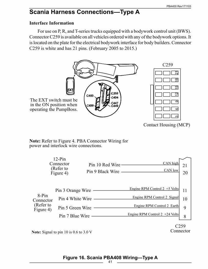
Scania Harness Connections—Type AInterface Information
For use on P, R, and T-series trucks equipped with a bodywork control unit (BWS). Connector C259 is available on all vehicles ordered with any of the bodywork options. It is located on the plate for the electrical bodywork interface for body builders. Connector C259 is white and has 21 pins. (February 2005 to 2015.)
Figure 16. Scania PBA408 Wiring—Type A
12
15
18
2
1
Contact Housing (MCP)
C259
3
6
9
Note: Refer to Figure 4. PBA Connector Wiring for power and interlock wire connections.
The EXT switch must be in the ON position when operating the PumpBoss.
12-Pin Connector (Refer to Figure 4)
8-Pin Connector (Refer to Figure 4)
C259 Connector
8Engine RPM Control 2 +24 Volts
CAN high 21
9 Engine RPM Control 2 Earth
11
10 Engine RPM Control 2 Signal
Engine RPM Control 2 +5 Volts
CAN low 20
Note: Signal to pin 10 is 0.6 to 3.0 V
Pin 9 Black WirePin 10 Red Wire
Pin 4 White Wire
Pin 5 Green Wire
Pin 3 Orange Wire
Pin 7 Blue Wire

PBA400 Rev171103
42
Scania BCI Harness Connections—Type DInterface Information
For use with BCI (Bodywork Communication Interface) module.
Figure 17. Scania BCI PBA408 Wiring—Type D
Note: Refer to Figure 4. PBA Connector Wiring for power and interlock wire connections.
Connector C493 is located in the bodywork console.
Positions in connector C493
12-Pin Connector (Refer to Figure 4)
J1939 CAN high 4J1939 CAN low 3
Pin 4 Red Wire
Pin 5 Black Wire
C493Connector

PBA400 Rev171103
43
Mercedes Harness ConnectionsInterface Information.
For 2007 and newer engines, the governor is designed to control engine throttle directly over the SAE J1939 databus. Remote throttle does not need to be enabled in the ECM.
Note: Refer to Figure 4. PBA Connector Wiring for power and interlock wire connections.
Figure 18. Mercedes PBA410 Wiring
VCU21-Pin
Connector
VCU18-Pin
Connector
17
18Remote Throttle Signal Analog
Remote PTO Power Supply
7Remote Accelerator Select Switch
J1939 (–)J1939 (Shield)
192120
J1939 (+)
14Sensor Ground (Throttle Pedal & Remote)
12-Pin Connector (Refer to Figure 4)
8-Pin Connector (Refer to Figure 4)
For 2006 and Older Engines
710Remote PTO Switch
Pin 7 Blue WirePin 4 White Wire
Pin 3 Orange WirePin 5 Green Wire
Pin 9 Black WirePin 8 White Wire
Pin 10 Red Wire
For 2007 and Newer Engines
J1939 CAN (–)
J1939 CAN (+)
2/16
2/17
2/18
12-Pin Connector (Refer to Figure 4)
Vehicle Interface Harness 18-Pin Connector #2
J1939 SHIELD
Pin 10 Red Wire
Pin 9 Black Wire
Pin 8 White Wire

PBA400 Rev171103
44
J1939 CAN Bus Control
U
V
J1939 (–)
J1939 (+)Pin 9 Black Wire
Pin 10 Red Wire
12-Pin Connector (Refer to Figure 4)
Figure 19. John Deere PBA416 Wiring
John Deere Harness ConnectionsInterface Information
CAN Controller will request a torque by means of TSC1. This option is disabled by default and is selectable in the Trim Options page for this application. Source address 57 should be programmed.
Note: Refer to Figure 4 Connector Wiring for Power and Interlock wire connections.
Circuit No. 905 Green
Circuit No. 904 Yellow
21 Pin Deutsch Connector
TIER-3PowerTech Engines
PBA400 Rev171103
45
J1939 CAN Bus Control
X1997/18
X1997/17
J1939 (–)
J1939 (+)Pin 9 Black Wire
Pin 10 Red Wire
12-Pin Connector (Refer to Figure 4)
18-Pin Connector X1997
Figure 20. MAN PBA424 Wiring
MAN Harness ConnectionsInterface Information
Parameters for various functions can be set on the KSM using MAN-cats II.The KSM can accept the Engine speed request from the Governor on the A-CAN.
Note: Refer to Figure 4 Connector Wiring for Power and Interlock wire connections.
Brown-Orange/0.75 A-CAN-L
Orange/0.75 A-CAN-H

PBA400 Rev171103
46
CAN Bus Control
4
6
(–)
(+)Pin 9 Black Wire
Pin 10 Red Wire
12-Pin Connector (Refer to Figure 4)
IVECO Harness ConnectionsInterface Information
The vehicles shall be ordered with EM w/ CANopen (OPT0384) and FMS (OPT14569). The CANopen XDC needs to be downloaded. This service is available from the official IVECO TeleService tool-chain worldwide. Also an adapter cable needs to be installed to connect Controller to the CAN Bus. This option is currently available only for EUROCARGO-V.
Note: Refer to Figure 4 for the Connector Wiring for Power and Interlock wire connections.
Wiring with PumpBoss device
VCM
EM
120Ω
PumpBoss12
0ΩST13
ST72072C ST72072C ST72072CST72072D
ST72070ST13
Vehicle Interface Harness9 Pin 72072C Connector
Pin 4 +
Pin 6 –
Ada
pter
NOTE: Contact IVECO dealer for information regarding the Adapter
Figure 21. IVECO PBA426 Wiring

PBA400 Rev171103
47Figure 22. High-Idle Wiring
High-Idle WiringThe governor programming includes a high-idle function. To activate the high-
idle provide + VDC to pin 7 (High-Idle Active Input) of the 12-pin connector and pin 6 (Interlock Input) of the 8-pin connector. The high-idle connection to pin 6 must be isolated form the interlock circuit using two diodes (see schematic).
Note: It is important that the connection to the Interlock Input from the High-Idle circuit be isolated from the apparatus interlock wiring with the two diodes. Refer to the wiring diagram. The pump must NOT be engaged when using the high idle function.
The high-idle is set at about 1000 RPM at the factory. (This value will vary depending on the specific engine.) To adjust this setting refer to High-Idle in the Operation Section.
A High-Idle Kit is available from FRC.Includes:ON/OFF SwitchIndicator LightTwo Diodes
To 8-Pin ConnectorPin 6 Yellow Wire
Interlock Input
To 12-Pin ConnectorPin 7 Violet Wire
High-Idle Active Input
High-Idle ON/OFF Switch
Diodes(IN4002 or equivalent)
From Transmission
Neutral+ VDC
Pump Engaged Indicator
Light
NC
NOC
ON
OFF
High-Idle Indicator
LightGND
FromPump
Engaged +12 VDC
GND
NC
NO
C
From Parking BrakeGND
NC
NO
C

PBA400 Rev171103
48
FLYBACK DIODE INFORMATIONIt is good engineering practice to include a flyback diode when switching an
inductive load (solenoid coil, relay coil, electric motor winding, etc.). It is recommended that a flyback diode be installed on inductive devices that share a common power source/ground with an FRC governor.
Figure 23. Flyback Diode
Typical circuit showing a flyback diode installed across an inductive load.
Diagram showing a flyback diode connected on a typical pump primer motor solenoid.
Diode
Inductive Load
GND
+V
Primer Motor Solenoid
+ VDC Supply
From Primer Motor Switch
To Primer Motor
Ground
+ –
Diode

PBA400 Rev171103
49
NOTES

PBA400 Rev171103
50
NOTES

PBA400 Rev171103
51
NOTES
PBA400 Rev171103
52