generator governor andgenerator governor and information ... dl/gen-governor-info-093010.pdf · •...
TRANSCRIPT

Generator Governor andGenerator Governor andGenerator Governor and Generator Governor and Information Settings WebinarInformation Settings Webinar
Robert W. Cummings - NERC Director of System Analysis and Reliability Initiatives
William Herbsleb - Chairman of Frequency Response Standard Drafting Team
Sydney Niemeyer - Control Systems Specialist NRG Energy
September 30, 2010

Survey InstructionsSurvey Instructions2
All generators rated 20 MVA or higher, or plants that g g , paggregate to a total of 75 MVA or greater net rating at point of interconnection (i.e., wind farms, PV farms, etc.), Statement of Compliance Registry Criteria Rev 5 0Statement of Compliance Registry Criteria, Rev. 5.0.
Jointly-owned units – reported by the operating entity.
C
–– –
Combined-cycle plants – combustion turbines and heat-recovery (steam turbine) units to be reported separately.
Wind farms report on a point of interconnection basis Wind farms – report on a point-of-interconnection basis.
If operable in more than one interconnection, complete the survey for operation in each of the interconnectionsthe survey for operation in each of the interconnections.

3Frequency Response ConcernsFrequency Response Concerns
3
Frequency Response is declining in Eastern Interconnection• Various factors are influencing• When is frequency response too low?
P i C t l F R i b i ithd Primary Control Frequency Response is being withdrawn Primary inertial generation being supplanted by non-inertial
resources – wind, solar, electronically coupled resourcesy• What is their response to frequency excursions?• What is their susceptibility to tripping during frequency
excursions?excursions? Load characteristics are changing
• Unknown frequency response characteristicsq y p• Current modeling is insufficient to analyze the phenomenon

4
Eastern Interconnection Mean Primary Eastern Interconnection Mean Primary Frequency Response TrendFrequency Response Trend

Eastern Interconnection Mean Primary Eastern Interconnection Mean Primary Frequency Response Frequency Response –– ProjectedProjected
55

6Classic Frequency Excursion RecoveryClassic Frequency Excursion Recovery
6
Excursion Recovery60.050
Frequency (Hz)
A = 60.00059 975
60.000
60.025 Recovery Completed, TV
59 900
59.925
59.950
59.975
B = 59.87459.850
59.875
59.900
C = 59.812
59.775
59.800
59.825
59.750-30 0 30 60 90 120 150 180 210 240 270 300 330 360 390 420
Time (Seconds)

Page 7Frequency PerformanceFrequency Performance
age
Arresting Period Rebound Period Recovery Period

8
Typical Frequency Traces Typical Frequency Traces Following Following a Unit Tripa Unit Trip 8o o go o g a U t pa U t p

Page 9
Frequency Response Basics Frequency Response Basics (Using a 1400 MW generation loss event as an example)(Using a 1400 MW generation loss event as an example)
age 9
1800
2000
60.05
60.10
ANERC Frequency Response =
1400
1600
e (M
W)
59.95
60.00A Generation Loss (MW)
FrequencyPoint A-FrequencyPoint B
Pre Event Frequency
1000
1200
ad R
espo
nse
59.85
59.90
uenc
y (H
z)BSettling Frequency:
Primary Response is almost all deployed
600
800
over
nor/L
oa
59.75
59.80 Freq
u
C Frequency Nadir:Generation and Load Response equals
the generation loss
Primary Response is almost all deployed
200
400
Go
59.65
59.70Governor Response
Load Response
Frequency
Slope of the dark green line illustrates the System Inertia (Generation and Load). The slope is ΔP/(D+2H)
00 2 4 6 8 10 12 14 16 18 20 22 24 26 28 30
Time (Seconds)
59.60

10Inertial Response VariabilityInertial Response Variability
0
High Inertia
Light Inertia

11Frequency Response BasicsFrequency Response Basics
Whys and Wherefores (things to examine)• Deadband currently typical setting is at ±36• Deadband — currently typical setting is at ±36
mHz ERCOT greatly improved frequency response byERCOT greatly improved frequency response by
reducing deadband to ± 16.6 mHz• Sliding pressure controls• MW setpoints — limited time of response• Blocked governor response• Once-through boilers• Gas Turbine inverse response

12
ERCOT Experiencep

13
Governor response “Steps” to the 5% droop curve at the dead band
Governor response is proportional at the dead-band reaching 5% at 3 Hz deviation 3
-0.04000 59.96000 4.69287 8.52357%
Frequency Grid FrequencyDeviation Frequency Response
Hz Hz MW Droop %
-0.04000 59.96000 8.00000 5.00000%
Frequency Grid FrequencyDeviation Frequency Response
Hz Hz MW Droop %
dead-banddeviation
%-0.03900 59.96100 4.49175 8.68258%-0.03800 59.96200 4.29064 8.85650%-0.03700 59.96300 4.08952 9.04752%-0.03600 59.96400 3.88840 9.25830%-0.03500 59.96500 3.68728 9.49208%-0.03400 59.96600 3.48617 9.75283%
%-0.03900 59.96100 7.80000 5.00000%-0.03800 59.96200 7.60000 5.00000%-0.03700 59.96300 7.40000 5.00000%-0.03600 59.96400 7.20000 5.00000%-0.03500 59.96500 0.00000 100.00000%-0.03400 59.96600 0.00000 100.00000%
Dead-band
-0.03300 59.96700 3.28505 10.04551%-0.03200 59.96800 3.08393 10.37636%-0.03100 59.96900 2.88281 10.75338%-0.03000 59.97000 2.68170 11.18694%-0.02900 59.97100 2.48058 11.69081%-0.02800 59.97200 2.27946 12.28359%0 02700 59 97300 2 07835 12 99110%
-0.03300 59.96700 0.00000 100.00000%-0.03200 59.96800 0.00000 100.00000%-0.03100 59.96900 0.00000 100.00000%-0.03000 59.97000 0.00000 100.00000%-0.02900 59.97100 0.00000 100.00000%-0.02800 59.97200 0.00000 100.00000%0 02700 59 97300 0 00000 100 00000%-0.02700 59.97300 2.07835 12.99110%
-0.02600 59.97400 1.87723 13.85020%-0.02500 59.97500 1.67611 14.91548%-0.02400 59.97600 1.47499 16.27125%-0.02300 59.97700 1.27388 18.05512%-0.02200 59.97800 1.07276 20.50786%0 02100 59 97900 0 87164 24 09245%
-0.02700 59.97300 0.00000 100.00000%-0.02600 59.97400 0.00000 100.00000%-0.02500 59.97500 0.00000 100.00000%-0.02400 59.97600 0.00000 100.00000%-0.02300 59.97700 0.00000 100.00000%-0.02200 59.97800 0.00000 100.00000%0 02100 59 97900 0 00000 100 00000%-0.02100 59.97900 0.87164 24.09245%
-0.02000 59.98000 0.67052 29.82737%-0.01900 59.98100 0.46941 40.47654%-0.01800 59.98200 0.26829 67.09147%-0.01700 59.98300 0.06717 100.00000%-0.01600 59.98400 0.00000 100.00000%
-0.02100 59.97900 0.00000 100.00000%-0.02000 59.98000 0.00000 100.00000%-0.01900 59.98100 0.00000 100.00000%-0.01800 59.98200 0.00000 100.00000%-0.01700 59.98300 0.00000 100.00000%-0.01600 59.98400 0.00000 100.00000%
Dead-band
600 MW Steam Turbine 5% Droop Setting
0.01666 Hz Dead-Band 0.036 Hz Dead-BandBAL-001-TRE-1 Implementation Common Industry Implementation

14
Close up look at +/-0.0166 Hz Dead Band with No Step Implementation
600 MW Generator
Frequency Response
150.00
Deadband Setting
0.0166 Hz600.000Capability (MW)
100.00
0.00
50.00
Cha
nge
No Step response at
-50.00
MW
dead-band.
-100.00
-150.0059.50 59.55 59.60 59.65 59.70 59.75 59.80 59.85 59.90 59.95 60.00 60.05 60.10 60.15 60.20 60.25 60.30 60.35 60.40 60.45 60.50
Hz
Droop Setting 5.00%

15Frequency Response Deadband Setting600.000Capability (MW)
Close up look at +/-0.036 Hz Dead Band with Step Implementation
600 MW Generator5q y p
150.00
Hzp y ( )
0.036
50.00
100.00
0.00
50.00
W C
hang
e
Step response at
-50.00
MW
dead-band.
150 00
-100.00
-150.0059.50 59.55 59.60 59.65 59.70 59.75 59.80 59.85 59.90 59.95 60.00 60.05 60.10 60.15 60.20 60.25 60.30 60.35 60.40 60.45 60.50
Hz
Droop Setting 5.00%

16ERCOT Frequency Profile Comparison
J th h A t f h Y 6
30000
35000January through August of each Year
25000
uran
ces
15000
20000
Min
ute
Occ
5000
10000
One
M
0
59.9
59.91
59.92
59.93
59.94
59.95
59.96
59.97
59.98
59.99 60
60.01
60.02
60.03
60.04
60.05
60.06
60.07
60.08
60.09 60
.1
59 59 59 59 59 59 59 59 59 59 60 60 60 60 60 60 60 60 60 60
2010 2008
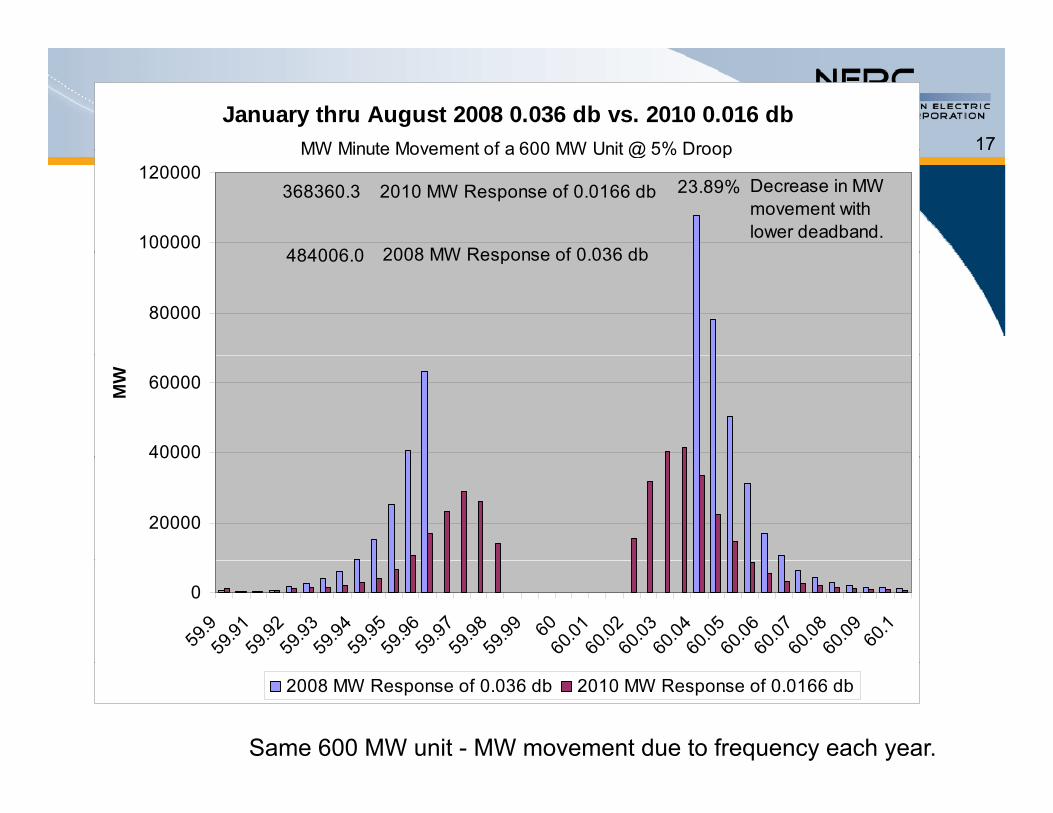
17January thru August 2008 0.036 db vs. 2010 0.016 db
MW Minute Movement of a 600 MW Unit @ 5% Droop
100000
120000
484006 0
368360.3 2010 MW Response of 0.0166 db 23.89% Decrease in MW movement with lower deadband.
2008 MW Response of 0 036 db
MW Minute Movement of a 600 MW Unit @ 5% Droop
80000
484006.0 2008 MW Response of 0.036 db
40000
60000MW
20000
40000
0
59.9
59.91
59.92
59.93
59.94
59.95
59.96
59.97
59.98
59.99 60
60.01
60.02
60.03
60.04
60.05
60.06
60.07
60.08
60.09 60
.1
Same 600 MW unit - MW movement due to frequency each year.
2008 MW Response of 0.036 db 2010 MW Response of 0.0166 db

188
Frequency Response Initiativeq y p

19FRI ObjectivesFRI Objectives
9
Coordinate all NERC standards development and performance analysis activities related to frequencyperformance analysis activities related to frequency response and control
Identify specific frequency-related reliability factorsy p q y y Identify root causes of changes in frequency
responsep Identify practices and methods to address root
causes Consider impacts of integration of new generation
technologies (such as wind, solar, and significant nuclear expansion)

20FRI ObjectivesFRI Objectives
0
Develop metrics and benchmarks to improve frequency response performance trackingfrequency response performance tracking
Share lessons learned with the industry via outreach, alerts, and webinarsoutreach, alerts, and webinars
Determine if performance-based frequency response standards are warrantedresponse standards are warranted

21NearNear--Term TasksTerm Tasks
Develop a clear set of terminology for use by NERC and the industry – Nearing completion
Issue a Recommendation (ROP § 810) and survey to collect data and information for analysis
Analyze current and historical Primary and Analyze current and historical Primary and Secondary Control Response performance – what factors influence that performance D l t t d th d f d t i i f Develop automated method for determining frequency deviation events to be used for BAs to measure Primary Control Response – Evaluating CERTS FMA Tool
Develop appropriate metrics for tracking frequency performance on each interconnection to monitor trends and performance
Develop sustainable methods for automatically collecting, trending, and analyzing various elements of frequency response and control for frequency deviation events

22MidMid--Term TasksTerm Tasks
Improve transient dynamic models of Primary Control Response for generators and other devices
Explore and analyze what are appropriate frequency response and control performance requirements to maintain system reliabilityrequirements to maintain system reliability
Determine appropriate minimum Bias settings for use in AGC systems as part of an overall Frequency Response and Control strategyResponse and Control strategy

23LongerLonger--Term Tasks Term Tasks –– 1 to 2 Years1 to 2 Years
3
Develop and implement mid-term dynamic modelsof Primary Control Response of generators and other d idevices• Research required
Analyze current Inertial Response performance and Analyze current Inertial Response performance and determine what factors influence performance
Examine Primary Control Frequency ResponseExamine Primary Control Frequency Response characteristics of electronically-coupled resources and “smart grid” loads• Develop load and “generator” models (research required)• Develop load and generator models (research required)
to properly analyze influence on system behavior in transient, post-transient, and mid-term stability
Explore how displacement of inertial generation with electronically-coupled resources might influence Inertial Response

24Reporting & Ongoing ActivitiesReporting & Ongoing Activities
Ongoing Activities Communications / Educational OutreachCommunications / Educational Outreach
• Technical Reference Documents• Webinars / Workshopsp
Metrics & Calculations• Ongoing determination of frequency events for analysis• Quarterly determination of response performance
Reporting on FRI Progress Oct 18 2010 Report to FERC Oct. 18, 2010 – Report to FERC Dec. 31, 2010 – Report to Board February 2011 – Report to Board and FERCFebruary 2011 Report to Board and FERC 2011 & 2012 Quarterly Reports to Board

255
Question & Answer

Survey InstructionsSurvey Instructions26
1. Unit name and number.
6
1. Unit name and number.
2. Balancing Authority (BA) in which the generator is operated (pull down)is operated (pull-down). a. If operable in more than one, please note all
applicable BAs–
applicable BAs.
b. If operable in more than one interconnection, complete the survey for operation in each of thecomplete the survey for operation in each of the interconnections.

Survey InstructionsSurvey Instructions27
3. Unit seasonal Net MW ratings normally3. Unit seasonal Net MW ratings normally reported to NERC for resource adequacy analyses:a. Summer Net MW rating
b Winter Net MW rating–
b. Winter Net MW rating
4. Prime mover (steam turbine, combustion turbine wind turbine etc pull down)turbine, wind turbine, etc. — pull-down)
5. Fuel type (coal, oil, nuclear, etc. — pull-down)

Survey InstructionsSurvey Instructions28
6. Unit inertia constant (H) as modeled in
8
6. Unit inertia constant (H) as modeled in dynamics analyses – the combined kinetic energy of the generator and prime-mover in watt-seconds at rated speed divided by the VA (Volt-Ampere) base.
7. What are the annual run hours for the unit (data for each of the last 3 years)?
8. What is the continuous MW rating (Pmax) of the unit?

Survey InstructionsSurvey Instructions29
9. What percent of time does the unit run at Pmax or
9
pvalves wide-open?
a. 0 to 30 %
b. 31 % to 60 %
c 61 % to 100 %c. 61 % to 100 %
10. Equipped with a Governor? (Y/N) If not, no further answers are necessary. , y

Survey InstructionsSurvey Instructions30
11. If yes, is the governor operational? (Y/N with a
30
y , g p (comment box) If not, please explain.
a. Is the governor normally in operation? (Y/N with a comment box) (even if not normally operated, the data on the governor is still needed)
f ?b. What is the normal governor mode of operation? (pull-down)
c Is the governor response sustainable for more thanc. Is the governor response sustainable for more than one minute if conditions remain outside of the deadband? (Y/N)

Survey InstructionsSurvey Instructions31
11. (continued)
3
d. Are there any regulatory restrictions regarding the operation of the governor? This should cover nuclear regulation, environmental restrictions (water uc ea egu at o , e o e ta est ct o s ( atetemperature, emissions), water flow, etc.
e. Does the governor respond beyond the high/low operating limit (boiler blocks)? (Y/N)
f. Is the governor response limited by the rate of change? (Y/N)
g. Are there any other unit-level or plant-level control h th t ld id li itschemes that would override or limit governor
performance? If yes, please explain.

Survey InstructionsSurvey Instructions32
12.Governor Type?
3
Electronic (analog electro-hydraulic);
DEH (digital electro hydraulic);DEH (digital electro hydraulic);
Mechanical;
Other — please specify
13.Governor manufacturer and model?13.Governor manufacturer and model? a. If mixed vendor equipment is installed, please
explain.p

Survey InstructionsSurvey Instructions33
14.Governor Deadband setting?
33
a. Deadband in(+/-) mHzi. If in mHz is the deadband centered around a frequency
reference (60 Hz or current frequency)?reference (60 Hz or current frequency)?
b. Deadband in (+/-) RPM i For RPM specify number of machine polesi. For RPM specify number of machine poles
ii. If in RPM, is the RPM reference nominal or current RPM?
c What is the basis for this setting?c. What is the basis for this setting?
d. Once activated, what are the conditions for which the governor action is reset?the governor action is reset?
Survey InstructionsSurvey Instructions34
15.What is the percentage (%) droop setting on the governor?
3
the governor? a. What is the basis for the droop setting?
16.Does the unit Frequency Response step into the droop curve or is it linear from the deadband?

Survey InstructionsSurvey Instructions35
17.Prime mover control mode – What is the ll d T bi C t l d ( )? If
35
normally used Turbine Control mode(s)? If more than one is prevalently used, select a primary and explainprimary and explain.
Turbine manual Pre-select
Thermally-limited
Turbine following
MW set point
Coordinated controlu b e o o g
Boiler following
Coo d ated co t o
Other (please explain)
Part-load explain)

Survey InstructionsSurvey Instructions36
18.Do market rules restrict or override governor speed controls? (Y/N) If yes please explain
36
speed controls? (Y/N) If yes, please explain.

Survey InstructionsSurvey Instructions37
For steam generator controls or central station controls:
3
19.Does the boiler control or combined cycle central station control have a frequency input?central station control have a frequency input? (Y/N) If yes, answer the following questions:
a Deadband in(+/-) mHza. Deadband in(+/-) mHzi. If in mHz is the deadband centered around a frequency
reference (60 Hz or current frequency)?
b. Deadband in (+/-) RPM i. For RPM specify number of machine poles
ii. If in RPM, is the RPM reference nominal or current RPM?
c. What is the basis for this setting?

Survey InstructionsSurvey Instructions38
20.Does the control’s Frequency Response step into the droop curve or is it linear from the
38
into the droop curve or is it linear from the deadband?
21.What is the steam turbine control mode? (boiler following, turbine following, coordinated control)control)
22.Do the unit or plant controls over-ride governor d t l th t l tspeed control or are the control parameters
supportive? (Y/N)

Survey InstructionsSurvey Instructions39
23.Does the boiler operate under variable/sliding pressure? (Y/N)
39
pressure? (Y/N)a. What is the control/governor valve position
percentage (%) during variable pressure operation?percentage (%) during variable pressure operation?
24.Do unit or plant economic controls over-ride d t l? (Y/N)governor speed control? (Y/N)

Eastern InterconnectionEastern Interconnection400
0706 UTC
306 Atl ti St d d306 Atlantic Standard406 Atlantic Daylight206 Eastern Standard306 Eastern Daylight106 Central Standard206 Central Daylight206 Central Daylight2406 Mountain Standard106 Mountain Daylight2306 P ifi St d d2306 Pacific Standard2406 Pacific Daylight

88--1616--10 Braidwood Trip10 Braidwood Trip41

Event Performance Data QuestionsEvent Performance Data Questions42
Interconnection Date Time Time Zone
Eastern 8/16/2010 1:06:15 CSTEastern 8/16/2010 1:06:15 CST
Western 8/12/2010 14:44:03 CST
Texas 8/20/2010 14:25:29 CST
Québec 12/10/2009 15:09:31 EST
Survey InstructionsSurvey Instructions43
25.Was the unit on-line during the event? (Y/N)
3
26.Pre-event generation (MW) – Enter the MW output of the generator at the time just before the event began.
27.Post-event generation (MW) – Enter the MW output of the generator after the event that was reflects the response by the governor to the f d i tifrequency deviation.
28.Time to achieve post-event response (seconds) – Enter the time (in seconds) it took to achieve the MW response in question 27.