pressure controls delta power company · pressure controls delta power company 4484 boeing drive -...
TRANSCRIPT

PRESSURE CONTROLS Delta Power Company 4484 Boeing Drive - Rockford, IL 61109
WARNING: The specifications/application data shown in our catalogs and data sheets are intended only as a general guide for the product described (herein). Any specific application should not be undertaken without independent study, evaluation, and testing for suitability.
Phone: (815) 397-6628 Fax: (815) 397-2526 E-mail: [email protected]
SECTION/Description Pages
Direct Acting and Differential Area Relief Valves 333 Pilot Operated Relief Valves 359 Crossover Relief Valves 375 Pressure Compensated Regulator Valves 381 Pressure Reducing/Relieving Valves 405 Sequence Valves 413 Shut Down Valves 437 Unloading Valves 441
Page 331

Page 332

PRESSURE CONTROLS Delta Power Company 4484 Boeing Drive - Rockford, IL 61109
WARNING: The specifications/application data shown in our catalogs and data sheets are intended only as a general guide for the product described (herein). Any specific application should not be undertaken without independent study, evaluation, and testing for suitability.
Phone: (815) 397-6628 Fax: (815) 397-2526 E-mail: [email protected]
Direct Acting and Differential Area Relief Valves Direct Acting Relief Valves
GPM PSI LPM BAR MODEL PAGE 12 3500 45 241 DE-RCA 334
5 3000 19 207 MA-RVA 336 6 3500 23 241 PB-RVA 338 8 4000 30 276 DE-RVA 340 6 3500 23 241 PB-RWA 342 8 4000 30 276 DE-RWA 344
Differential Area Relief Valves
GPM PSI LPM BAR MODEL PAGE 15 3500 57 241 DE-RCD 346
8 3500 30 241 PB-RVD 348 15 4000 57 276 DE-RVD 350 40 5000 151 345 HE-RVD 352 8 3500 30 241 PB-RWD 354 15 4000 57 276 DE-RWD 356
Typical Schematic Typical application for the RVA, RVD, RWA, RWD is to protect pump and system. Typical application for the RCA and RCD is cross over relief to protect motor in both directions, where lowest possible price is desired.
1 2
1 2
Page 333

PRESSURE CONTROLS Delta Power Company
4484 Boeing Drive - Rockford, IL 61109
WARNING: The specifications/application data shown in our catalogs and data sheets are intended only as a general guide for the product described (herein). Any specific application should not be undertaken without independent study, evaluation, and testing for suitability.
Phone: (815) 397-6628 Fax: (815) 397-2526 E-mail: [email protected]
DE-RCA Guided Ball, Direct Acting Relief Valve
DESCRIPTION 10 size, 7/8-14 thread, “Delta” series, direct acting relief valve. OPERATION The DE-RCA blocks flow from (2) to (1) until sufficient pressure is present at (2) to force the poppet to open and allow metered flow from (2) to (1). The cartridge offers smooth transition in response to load changes in common hydraulic circuits. FEATURES
• Hardened parts for long life. • Industry common cavity.
HYDRAULIC SYMBOL
Installation Space Saving Product. Cannot be field adjusted. Not recommended for crossover relief valve applications, use DE-RWA
PERFORMANCE Actual Test Data (Cartridge Only) VALVE SPECIFICATIONS
Nominal Flow 12 GPM (45 LPM) Rated Operating Pressure 3500 PSI (241 bar) Viscosity Range 36 to 3000 SSU (3 to 647 cSt) Filtration ISO 18/16/13 Media Operating Temperature Range -40° to 250° F (-40° to 120° C)
Weight .38 lbs. (.17 kg) Operating Fluid Media General Purpose Hydraulic Fluid Cartridge Torque Requirements 30 ft-lbs (40.6 Nm)
Cavity DELTA 2W Cavity Form Tool (Finishing) 40500000
Seal Kit 21191200
0
500
1000
1500
2000
2500
3000
3500
4000
4500
0 2 4 6 8 10 12 14 16
Flow (GPM)
Pre
ssur
e D
rop
(PS
I)
0
50
100
150
200
250
300
0 5 10 15 20 25 30 35 40 45 50 55 60
Flow (LPM)
Pre
ssur
e D
rop
(BA
R)
2500 3500
Page 334

PRESSURE CONTROLS Delta Power Company
4484 Boeing Drive - Rockford, IL 61109
WARNING: The specifications/application data shown in our catalogs and data sheets are intended only as a general guide for the product described (herein). Any specific application should not be undertaken without independent study, evaluation, and testing for suitability.
Phone: (815) 397-6628 Fax: (815) 397-2526 E-mail: [email protected]
DIMENSIONS
ORDERING INFORMATION DE-RCA - - -
OPTIONS BODIES
Buna Standard 00 Blank Without Body Viton Standard V0 N 3/8 NPTF Ports
S #8 SAE Ports PRESSURE RANGE/SETTING 2500 100 – 2500 PSI 3500 250 – 3500 PSI
Page 335

PRESSURE CONTROLS Delta Power Company 4484 Boeing Drive - Rockford, IL 61109
WARNING: The specifications/application data shown in our catalogs and data sheets are intended only as a general guide for the product described (herein). Any specific application should not be undertaken without independent study, evaluation, and testing for suitability.
Phone: (815) 397-6628 Fax: (815) 397-2526 E-mail: [email protected]
MA-RVA Direct Acting Relief Valve
DESCRIPTION 7 size, 5/8-18 thread, “Mini” series, direct acting relief valve. OPERATION The MA-RVA blocks flow from (2) to (1) until sufficient pressure is present at (2) to force the poppet to open and allow metered flow from (2) to (1) The cartridge offers smooth transition in response to load changes in common hydraulic circuits. FEATURES
• Hardened parts for long life. • Industry common cavity.
HYDRAULIC SYMBOL
PERFORMANCE Actual Test Data (Cartridge Only) VALVE SPECIFICATIONS
Nominal Flow 5 GPM (19 LPM) Rated Operating Pressure 3000 PSI (207 bar) Viscosity Range 36 to 3000 SSU (3 to 647 cSt) Filtration ISO 18/16/13 Media Operating Temperature Range -40° to 250° F (-40° to 120° C)
Weight .39 lbs. (1.7kg) Operating Fluid Media General Purpose Hydraulic Fluid Cartridge Torque Requirements 15 ft-lbs (20.3 Nm)
Cavity MINI 2W Cavity Form Tool (Finishing) 40500003 Seal Kit 21191000
0
500
1000
1500
2000
2500
3000
3500
4000
0 2 4 6 8
Flow (GPM)
Pres
sure
Dro
p (P
SI)
0
50
100
150
200
250
0 5 10 15 20 25 30Flow (LPM)
Pres
sure
Dro
p (B
AR
)
Port 2 to 1 Port 2 to 1 Port 2 to 1
Page 336

PRESSURE CONTROLS Delta Power Company 4484 Boeing Drive - Rockford, IL 61109
WARNING: The specifications/application data shown in our catalogs and data sheets are intended only as a general guide for the product described (herein). Any specific application should not be undertaken without independent study, evaluation, and testing for suitability.
Phone: (815) 397-6628 Fax: (815) 397-2526 E-mail: [email protected]
DIMENSIONS
ORDERING INFORMATION MA-RVA - - -
OPTIONS BODIES
Buna Standard 00 Blank Without Body Viton Standard V0 N ¼ NPTF Ports
Buna, Knob 0K S #6 SAE Ports Viton, Knob VK
PRESSURE RANGE 0500 100-500 PSI 1500 500-1500 PSI 3000 1500-3000 PSI
Page 337

PRESSURE CONTROLS Delta Power Company 4484 Boeing Drive - Rockford, IL 61109
WARNING: The specifications/application data shown in our catalogs and data sheets are intended only as a general guide for the product described (herein). Any specific application should not be undertaken without independent study, evaluation, and testing for suitability.
Phone: (815) 397-6628 Fax: (815) 397-2526 E-mail: [email protected]
PB-RVA Direct Acting Relief Valve
DESCRIPTION 8 size, 3/4-16 thread, “Power” series, direct acting relief valve. OPERATION The PB-RVA blocks flow from (2) to (1) until sufficient pressure is present at (2) to force the poppet to open and allow metered flow from (2) to (1) The cartridge offers smooth transition in response to load changes in common hydraulic circuits. FEATURES
• Hardened parts for long life. • Industry common cavity.
HYDRAULIC SYMBOL
PERFORMANCE Actual Test Data (Cartridge Only) VALVE SPECIFICATIONS
Nominal Flow 6 GPM (23 LPM) Rated Operating Pressure 3500 PSI (241 bar) Viscosity Range 36 to 3000 SSU (3 to 647 cSt) Filtration ISO 18/16/13 Media Operating Temperature Range -40° to 250° F (-40° to 120° C)
Weight .30 lbs. (.14 kg) Operating Fluid Media General Purpose Hydraulic Fluid Cartridge Torque Requirements 25 ft-lbs (34 Nm)
Cavity POWER 2W Cavity Form Tool (Finishing) 40500005 Seal Kit 21191100
0500
10001500200025003000350040004500
0 2 4 6 8 10
Flow (GPM)
Pres
sure
Dro
p (P
SI)
0
50
100
150
200
250
300
0 5 10 15 20 25 30 35
Flow (LPM)
Pres
sure
Dro
p (B
AR
)
Port 2 to 1 Port 2 to 1 Port 2 to 1
Page 338

PRESSURE CONTROLS Delta Power Company 4484 Boeing Drive - Rockford, IL 61109
WARNING: The specifications/application data shown in our catalogs and data sheets are intended only as a general guide for the product described (herein). Any specific application should not be undertaken without independent study, evaluation, and testing for suitability.
Phone: (815) 397-6628 Fax: (815) 397-2526 E-mail: [email protected]
DIMENSIONS
ORDERING INFORMATION PB-RVA - - -
OPTIONS BODIES
Buna Standard 00 Blank Without Body Viton Standard V0 N 1/4 NPTF Ports
Buna, Knob 0K S #6 SAE Ports Viton, Knob VK
PRESSURE RANGE/SETTING 0800 100 - 800 PSI 2000 800 - 2000 PSI 3500 2000 – 3500 PSI
Page 339
PRESSURE CONTROLS Delta Power Company 4484 Boeing Drive - Rockford, IL 61109
WARNING: The specifications/application data shown in our catalogs and data sheets are intended only as a general guide for the product described (herein). Any specific application should not be undertaken without independent study, evaluation, and testing for suitability.
Phone: (815) 397-6628 Fax: (815) 397-2526 E-mail: [email protected]
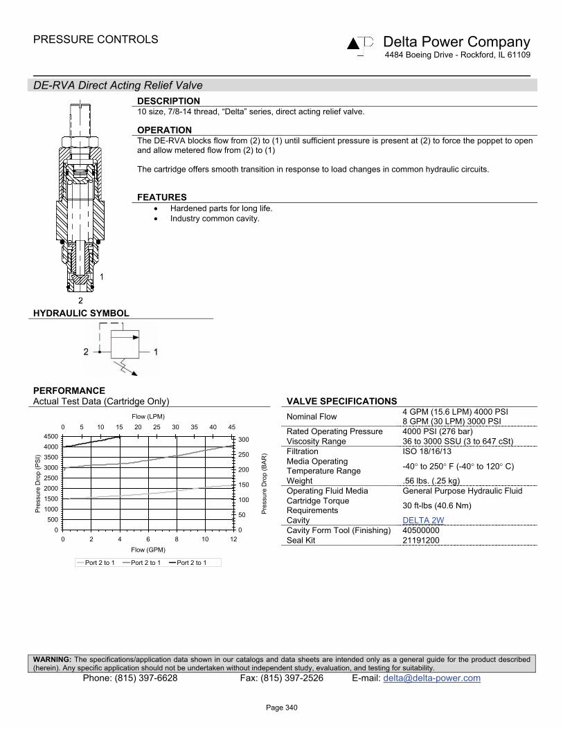
DE-RVA Direct Acting Relief Valve
DESCRIPTION 10 size, 7/8-14 thread, “Delta” series, direct acting relief valve. OPERATION The DE-RVA blocks flow from (2) to (1) until sufficient pressure is present at (2) to force the poppet to open and allow metered flow from (2) to (1) The cartridge offers smooth transition in response to load changes in common hydraulic circuits. FEATURES
• Hardened parts for long life. • Industry common cavity.
HYDRAULIC SYMBOL
PERFORMANCE Actual Test Data (Cartridge Only) VALVE SPECIFICATIONS
Nominal Flow 4 GPM (15.6 LPM) 4000 PSI 8 GPM (30 LPM) 3000 PSI
Rated Operating Pressure 4000 PSI (276 bar) Viscosity Range 36 to 3000 SSU (3 to 647 cSt) Filtration ISO 18/16/13 Media Operating Temperature Range -40° to 250° F (-40° to 120° C)
Weight .56 lbs. (.25 kg) Operating Fluid Media General Purpose Hydraulic Fluid Cartridge Torque Requirements 30 ft-lbs (40.6 Nm)
Cavity DELTA 2W Cavity Form Tool (Finishing) 40500000
Seal Kit 21191200
0500
10001500200025003000350040004500
0 2 4 6 8 10 12Flow (GPM)
Pre
ssur
e D
rop
(PS
I)
0
50
100
150
200
250
300
0 5 10 15 20 25 30 35 40 45Flow (LPM)
Pre
ssur
e D
rop
(BA
R)
Port 2 to 1 Port 2 to 1 Port 2 to 1
Page 340

PRESSURE CONTROLS Delta Power Company 4484 Boeing Drive - Rockford, IL 61109
WARNING: The specifications/application data shown in our catalogs and data sheets are intended only as a general guide for the product described (herein). Any specific application should not be undertaken without independent study, evaluation, and testing for suitability.
Phone: (815) 397-6628 Fax: (815) 397-2526 E-mail: [email protected]
DIMENSIONS
ORDERING INFORMATION DE-RVA - - -
OPTIONS BODIES
Buna Standard 00 Blank Without Body Viton Standard V0 N 3/8 NPTF Ports
Buna, Knob 0K S #8 SAE Ports Viton, Knob VK
PRESSURE RANGE/SETTING 1500 200 – 1500 PSI 3000 1500 – 3000 PSI 4000 2500 – 4000 PSI
Page 341

PRESSURE CONTROLS Delta Power Company 4484 Boeing Drive - Rockford, IL 61109
WARNING: The specifications/application data shown in our catalogs and data sheets are intended only as a general guide for the product described (herein). Any specific application should not be undertaken without independent study, evaluation, and testing for suitability.
Phone: (815) 397-6628 Fax: (815) 397-2526 E-mail: [email protected]
PB-RWA Direct Acting Relief Valve
DESCRIPTION 8 size, 3/4-16 thread, “Power” series, direct acting relief valve. OPERATION The PB-RWA blocks flow from (2) to (1) until sufficient pressure is present at (2) to force the poppet to open and allow metered flow from (2) to (1) The cartridge offers smooth transition in response to load changes in common hydraulic circuits. FEATURES
• Hardened parts for long life. • Industry common cavity.
HYDRAULIC SYMBOL
PERFORMANCE Actual Test Data (Cartridge Only) VALVE SPECIFICATIONS
Nominal Flow 6 GPM (23 LPM) Rated Operating Pressure 3500 PSI (241 bar) Viscosity Range 36 to 3000 SSU (3 to 647 cSt) Filtration ISO 18/16/13 Media Operating Temperature Range -40° to 250° F (-40° to 120° C)
Weight .31 lbs. (.14 kg) Operating Fluid Media General Purpose Hydraulic Fluid Cartridge Torque Requirements 25 ft-lbs (34 Nm)
Cavity POWER 2W Cavity Form Tool (Finishing) 40500005 Seal Kit 21191100
0500
10001500200025003000350040004500
0 2 4 6 8 10
Flow (GPM)
Pres
sure
Dro
p (P
SI)
0
50
100
150
200
250
300
0 5 10 15 20 25 30 35
Flow (LPM)
Pres
sure
Dro
p (B
AR
)
Port 2 to 1 Port 2 to 1
Page 342

PRESSURE CONTROLS Delta Power Company 4484 Boeing Drive - Rockford, IL 61109
WARNING: The specifications/application data shown in our catalogs and data sheets are intended only as a general guide for the product described (herein). Any specific application should not be undertaken without independent study, evaluation, and testing for suitability.
Phone: (815) 397-6628 Fax: (815) 397-2526 E-mail: [email protected]
DIMENSIONS
ORDERING INFORMATION PB-RWA - - -
OPTIONS BODIES
External Adj. W/Locknut Buna 00 Blank Without Body External Adj. W/Locknut Viton V0 N 1/4 NPTF Ports
Buna, Knob 0K S #6 SAE Ports Viton, Knob VK
Internal Adj. Buna 0I Internal Adj. Viton VI PRESSURE RANGE/SETTING
Tamper Proof Buna 0T Ext./Int. Adjustable Tamper Proof Viton VT 1000 100 - 1000 PSI
3500 500 – 3500 PSI Tamper Proof Fill in 4 Digit Pressure Setting Example: 0500 – 500 PSI
Page 343

PRESSURE CONTROLS Delta Power Company 4484 Boeing Drive - Rockford, IL 61109
WARNING: The specifications/application data shown in our catalogs and data sheets are intended only as a general guide for the product described (herein). Any specific application should not be undertaken without independent study, evaluation, and testing for suitability.
Phone: (815) 397-6628 Fax: (815) 397-2526 E-mail: [email protected]
DE-RWA Direct Acting Relief Valve
DESCRIPTION 10 size, 7/8-14 thread, “Delta” series, direct acting relief valve OPERATION The DE-RWA blocks flow from (2) to (1) until sufficient pressure is present at (2) to force the poppet to open and allow metered flow from (2) to (1). The cartridge offers smooth transition in response to load changes in common hydraulic circuits. FEATURES
• Hardened parts for long life. • Industry common cavity.
HYDRAULIC SYMBOL
For critical leakage applications consult factory.
PERFORMANCE Actual Test Data (Cartridge Only) VALVE SPECIFICATIONS
Nominal Flow 8 GPM (30 LPM) Rated Operating Pressure 4000 PSI (276 bar) Viscosity Range 36 to 3000 SSU (3 to 647 cSt) Filtration ISO 18/16/13 Media Operating Temperature Range -40° to 250° F (-40° to 120° C)
Weight .51 lbs. (.23 kg) Operating Fluid Media General Purpose Hydraulic Fluid Cartridge Torque Requirements 30 ft-lbs (40.6 Nm)
Cavity DELTA 2W Cavity Form Tool (Finishing) 40500000
Seal Kit 21191200
0
500
1000
1500
2000
2500
3000
3500
4000
0 2 4 6 8 10 12Flow (GPM)
Pre
ssur
e D
rop
(PS
I)
0
50
100
150
200
250
0 5 10 15 20 25 30 35 40 45Flow (LPM)
Pre
ssur
e D
rop
(BA
R)
Port 2 to 1 Port 2 to 1
Page 344

PRESSURE CONTROLS Delta Power Company 4484 Boeing Drive - Rockford, IL 61109
WARNING: The specifications/application data shown in our catalogs and data sheets are intended only as a general guide for the product described (herein). Any specific application should not be undertaken without independent study, evaluation, and testing for suitability.
Phone: (815) 397-6628 Fax: (815) 397-2526 E-mail: [email protected]
DIMENSIONS
ORDERING INFORMATION DE-RWA - - -
OPTIONS BODIES
External Adj. W/Locknut, Buna 00 Blank Without Body External Adj. W/Locknut, Viton V0 N 3/8 NPTF Ports
Buna, Knob 0K S #8 SAE Ports Viton, Knob VK
Internally Adj. Buna 0I Internally Adj. Viton VI PRESSURE RANGE/SETTING
Tamper Proof, Buna 0T Ext./Int. Adjustment Tamper Proof, Viton VT 0500 100 – 500 PSI
3000 100 – 3000 PSI 4000 3000 – 4000 PSI Tamper Proof Fill In 4 Digit Pressure Setting Example: 0500 – 500 PSI
Page 345

PRESSURE CONTROLS Delta Power Company
4484 Boeing Drive - Rockford, IL 61109
WARNING: The specifications/application data shown in our catalogs and data sheets are intended only as a general guide for the product described (herein). Any specific application should not be undertaken without independent study, evaluation, and testing for suitability.
Phone: (815) 397-6628 Fax: (815) 397-2526 E-mail: [email protected]
DE-RCD Differential Area Relief Valve
DESCRIPTION 10 size, 7/8-14 thread, “Delta” series, differential area relief valve OPERATION The DE-RCD blocks flow from (1) to (2) until sufficient pressure is present at (1) to force the poppet to open and allow metered flow from (1) to (2). The cartridge offers smooth transition in response to load changes in common hydraulic circuits. FEATURES
• Hardened parts for long life. • Industry common cavity.
HYDRAULIC SYMBOL
Installation Space Saving Product. Cannot be field adjusted. Not recommended for crossover relief valve applications, use DE-RWD.
PERFORMANCE Actual Test Data (Cartridge Only) VALVE SPECIFICATIONS
Nominal Flow 15 GPM (57 LPM) Rated Operating Pressure 3500 PSI (241 bar) Viscosity Range 36 to 3000 SSU (3 to 647 cSt) Filtration ISO 18/16/13 Media Operating Temperature Range -40° to 250° F (-40° to 120° C)
Weight .37 lbs. (.17 kg) Operating Fluid Media General Purpose Hydraulic Fluid Cartridge Torque Requirements 30 ft-lbs (40.6 Nm)
Cavity DELTA 2W Cavity Form Tool (Finishing) 40500000
Seal Kit 21191200
0
500
1000
1500
2000
2500
3000
3500
4000
0 2 4 6 8 10 12 14 16
Flow (GPM)
Pre
ssur
e D
rop
(PS
I)
0
50
100
150
200
250
0 5 10 15 20 25 30 35 40 45 50 55 60
Flow (LPM)
Pre
ssur
e D
rop
(BA
R)
2500 3500
Page 346

PRESSURE CONTROLS Delta Power Company
4484 Boeing Drive - Rockford, IL 61109
WARNING: The specifications/application data shown in our catalogs and data sheets are intended only as a general guide for the product described (herein). Any specific application should not be undertaken without independent study, evaluation, and testing for suitability.
Phone: (815) 397-6628 Fax: (815) 397-2526 E-mail: [email protected]
DIMENSIONS
ORDERING INFORMATION DE-RCD - - -
OPTIONS BODIES
Buna Standard 00 Blank Without Body Viton Standard V0 N 3/8 NPTF Ports
S #8 SAE Ports PRESSURE RANGE/SETTING 2500 100 – 2500 PSI 3500 250 – 3500 PSI
Page 347

PRESSURE CONTROLS Delta Power Company 4484 Boeing Drive - Rockford, IL 61109
WARNING: The specifications/application data shown in our catalogs and data sheets are intended only as a general guide for the product described (herein). Any specific application should not be undertaken without independent study, evaluation, and testing for suitability.
Phone: (815) 397-6628 Fax: (815) 397-2526 E-mail: [email protected]
PB-RVD Differential Area Relief Valve
DESCRIPTION 8 size, 3/4-16 thread, “Power” series, differential area relief valve. OPERATION The PB-RVD blocks flow from (1) to (2) until sufficient pressure is present at (1) to force the poppet to open and allow metered flow from (1) to (2). The cartridge offers smooth transition in response to load changes in common hydraulic circuits. FEATURES
• Hardened parts for long life. • Industry common cavity.
HYDRAULIC SYMBOL
PERFORMANCE Actual Test Data (Cartridge Only) VALVE SPECIFICATIONS
Nominal Flow 8 GPM (30 LPM) Rated Operating Pressure 3500 PSI (241 bar) Viscosity Range 36 to 3000 SSU (3 to 647 cSt) Filtration ISO 18/16/13 Media Operating Temperature Range -40° to 250° F (-40° to 120° C)
Weight .31 lbs. (.14 kg) Operating Fluid Media General Purpose Hydraulic Fluid Cartridge Torque Requirements 25 ft-lbs (34 Nm)
Cavity POWER 2W Cavity Form Tool (Finishing) 40500005 Seal Kit 21191100
0500
1000150020002500300035004000
0 2 4 6 8 10
Flow (GPM)
Pres
sure
Dro
p (P
SI)
0
50
100
150
200
250
0 5 10 15 20 25 30 35Flow (LPM)
Pres
sure
Dro
p (B
AR
)
Port 1 to 2 Port 1 to 2 Port 1 to 2
Page 348

PRESSURE CONTROLS Delta Power Company 4484 Boeing Drive - Rockford, IL 61109
WARNING: The specifications/application data shown in our catalogs and data sheets are intended only as a general guide for the product described (herein). Any specific application should not be undertaken without independent study, evaluation, and testing for suitability.
Phone: (815) 397-6628 Fax: (815) 397-2526 E-mail: [email protected]
DIMENSIONS
ORDERING INFORMATION PB-RVD - - -
OPTIONS BODIES
Buna Standard 00 Blank Without Body Viton Standard V0 N 1/4 NPTF Ports
Buna, Knob 0K S #6 SAE Ports Viton, Knob VK
PRESSURE RANGE/SETTING 0800 100 - 800 PSI 2000 800 - 2000 PSI 3500 2000 – 3500 PSI
Page 349
PRESSURE CONTROLS Delta Power Company 4484 Boeing Drive - Rockford, IL 61109
WARNING: The specifications/application data shown in our catalogs and data sheets are intended only as a general guide for the product described (herein). Any specific application should not be undertaken without independent study, evaluation, and testing for suitability.
Phone: (815) 397-6628 Fax: (815) 397-2526 E-mail: [email protected]
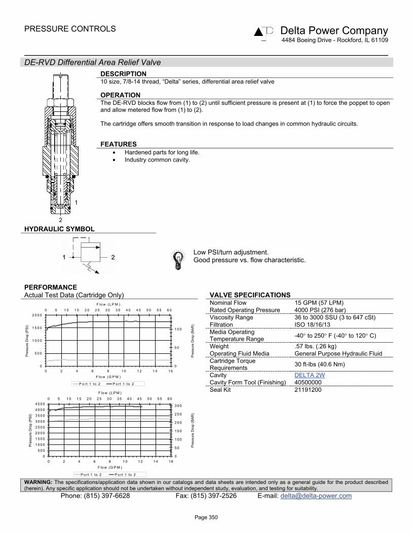
DE-RVD Differential Area Relief Valve
DESCRIPTION 10 size, 7/8-14 thread, “Delta” series, differential area relief valve OPERATION The DE-RVD blocks flow from (1) to (2) until sufficient pressure is present at (1) to force the poppet to open and allow metered flow from (1) to (2). The cartridge offers smooth transition in response to load changes in common hydraulic circuits. FEATURES
• Hardened parts for long life. • Industry common cavity.
HYDRAULIC SYMBOL
Low PSI/turn adjustment. Good pressure vs. flow characteristic.
PERFORMANCE Actual Test Data (Cartridge Only) VALVE SPECIFICATIONS
Nominal Flow 15 GPM (57 LPM) Rated Operating Pressure 4000 PSI (276 bar) Viscosity Range 36 to 3000 SSU (3 to 647 cSt) Filtration ISO 18/16/13 Media Operating Temperature Range -40° to 250° F (-40° to 120° C)
Weight .57 lbs. (.26 kg) Operating Fluid Media General Purpose Hydraulic Fluid Cartridge Torque Requirements 30 ft-lbs (40.6 Nm)
Cavity DELTA 2W Cavity Form Tool (Finishing) 40500000
Seal Kit 21191200
0
5 0 0
1 0 0 0
1 5 0 0
2 0 0 0
0 2 4 6 8 1 0 1 2 1 4 1 6F lo w (G P M )
Pre
ssur
e D
rop
(PS
I)
0
5 0
1 0 0
0 5 1 0 1 5 2 0 2 5 3 0 3 5 4 0 4 5 5 0 5 5 6 0F lo w (L P M )
Pre
ssur
e D
rop
(BA
R)
P o r t 1 to 2 P o r t 1 to 2
05 0 0
1 0 0 01 5 0 02 0 0 02 5 0 03 0 0 03 5 0 04 0 0 04 5 0 0
0 2 4 6 8 1 0 1 2 1 4 1 6F lo w (G P M )
Pre
ssur
e D
rop
(PS
I)
0
5 0
1 0 0
1 5 0
2 0 0
2 5 0
3 0 0
0 5 1 0 1 5 2 0 2 5 3 0 3 5 4 0 4 5 5 0 5 5 6 0F lo w (L P M )
Pre
ssur
e D
rop
(BA
R)
P o rt 1 to 2 P o rt 1 to 2
Page 350

PRESSURE CONTROLS Delta Power Company 4484 Boeing Drive - Rockford, IL 61109
WARNING: The specifications/application data shown in our catalogs and data sheets are intended only as a general guide for the product described (herein). Any specific application should not be undertaken without independent study, evaluation, and testing for suitability.
Phone: (815) 397-6628 Fax: (815) 397-2526 E-mail: [email protected]
DIMENSIONS
ORDERING INFORMATION DE-RVD - - -
OPTIONS BODIES
Buna Standard 00 Blank Without Body Viton Standard V0 N 3/8 NPTF Ports
Buna, Screen A0 S #8 SAE Ports Viton, Screen W0
Buna, Knob 0K Viton, Knob VK PRESSURE RANGE/SETTING
Buna, Knob, Screen AK 0200 50 – 200 PSI Viton, Knob, Screen WK 1500 200 – 1500 PSI
3000 1500 – 3000 PSI 4000 2500 – 4000 PSI Note: Use screen only if flow direction
is from (1) to (2).
Page 351

PRESSURE CONTROLS Delta Power Company 4484 Boeing Drive - Rockford, IL 61109
WARNING: The specifications/application data shown in our catalogs and data sheets are intended only as a general guide for the product described (herein). Any specific application should not be undertaken without independent study, evaluation, and testing for suitability.
Phone: (815) 397-6628 Fax: (815) 397-2526 E-mail: [email protected]
HE-RVD Differential Area Relief Valve
DESCRIPTION 10 size, 7/8-14 thread, “Delta” series, differential area relief valve OPERATION The HE-RVD blocks flow from (1) to (2) until sufficient pressure is present at (1) to force the poppet to open and allow metered flow from (1) to (2). The cartridge offers smooth transition in response to load changes in common hydraulic circuits. FEATURES
• Hardened parts for long life. • Industry common cavity.
HYDRAULIC SYMBOL
Good pressure vs. flow characteristic.
Recommended Return Line Pressure as shown on Performance Data Graph. Undercut Cavity Recommended for Max. flows.
(Consult Factory for Details)
PERFORMANCE Actual Test Data (Cartridge Only)
VALVE SPECIFICATIONS
0 10 20 30 40 50 60 70 80 90 100 110 120 130
‐40
10
60
110
160
210
260
310
0
500
1000
1500
2000
2500
3000
3500
4000
4500
0 5 10 15 20 25 30 35
Flow (LPM)
Pressure (B
AR)
Pressure (P
SI)
Flow (GPM)
Port 1 to 2 Tank Port 1 to 2
Nominal Flow 40 GPM (151 LPM) Rated Operating Pressure 5000 PSI (310 bar) Viscosity Range 36 to 3000 SSU (3 to 647 cSt) Filtration ISO 18/16/13 Media Operating Temperature Range -40° to 250° F (-40° to 120° C)
Weight .57 lbs. (.26 kg) Operating Fluid Media General Purpose Hydraulic Fluid Cartridge Torque Requirements 50 ft-lbs (67.8 Nm)
Cavity DELTA 2W Cavity Form Tool (Finishing) 40500000 Seal Kit 21191200
Page 352

PRESSURE CONTROLS Delta Power Company 4484 Boeing Drive - Rockford, IL 61109
WARNING: The specifications/application data shown in our catalogs and data sheets are intended only as a general guide for the product described (herein). Any specific application should not be undertaken without independent study, evaluation, and testing for suitability.
Phone: (815) 397-6628 Fax: (815) 397-2526 E-mail: [email protected]
DIMENSIONS
ORDERING INFORMATION HE-RVD - - -
OPTIONS BODIES Note: Aluminum, NOT durability rated for
Buna Standard 00 Blank Without Body 4000 PSI. Consult factory options. Viton Standard V0 N 3/8 NPTF Ports
Buna, Screen A0 S #8 SAE Ports Viton, Screen W0
Buna, Knob 0K Viton, Knob VK PRESSURE RANGE/SETTING
Buna, Knob, Screen AK 5000 1000-5000 PSI Viton, Knob, Screen WK
Note: Use screen only if flow direction
is from (1) to (2).
Page 353

PRESSURE CONTROLS Delta Power Company 4484 Boeing Drive - Rockford, IL 61109
WARNING: The specifications/application data shown in our catalogs and data sheets are intended only as a general guide for the product described (herein). Any specific application should not be undertaken without independent study, evaluation, and testing for suitability.
Phone: (815) 397-6628 Fax: (815) 397-2526 E-mail: [email protected]
PB-RWD Differential Area Relief Valve
DESCRIPTION 8 size, 3/4-16 thread, “Power” series, differential area relief valve. OPERATION The PB-RWD blocks flow from (1) to (2) until sufficient pressure is present at (1) to force the poppet to open and allow metered flow from (1) to (2). The cartridge offers smooth transition in response to load changes in common hydraulic circuits. FEATURES
• Hardened parts for long life. • Industry common cavity.
HYDRAULIC SYMBOL
PERFORMANCE Actual Test Data (Cartridge Only) VALVE SPECIFICATIONS
Nominal Flow 8 GPM (30 LPM) Rated Operating Pressure 3500 PSI (241 bar) Viscosity Range 36 to 3000 SSU (3 to 647 cSt) Filtration ISO 18/16/13 Media Operating Temperature Range -40° to 250° F (-40° to 120° C)
Weight .32 lbs. (.15 kg) Operating Fluid Media General Purpose Hydraulic Fluid Cartridge Torque Requirements 25 ft-lbs (34 Nm)
Cavity POWER 2W Cavity Form Tool (Finishing) 40500005 Seal Kit 21191100
0
500
1000
1500
2000
2500
3000
3500
4000
0 2 4 6 8 10
Flow (GPM)
Pres
sure
Dro
p (P
SI)
0
50
100
150
200
250
0 5 10 15 20 25 30 35
Flow (LPM)
Pres
sure
Dro
p (B
AR
)
Port 1 to 2 Port 1 to 2
Page 354

PRESSURE CONTROLS Delta Power Company 4484 Boeing Drive - Rockford, IL 61109
WARNING: The specifications/application data shown in our catalogs and data sheets are intended only as a general guide for the product described (herein). Any specific application should not be undertaken without independent study, evaluation, and testing for suitability.
Phone: (815) 397-6628 Fax: (815) 397-2526 E-mail: [email protected]
DIMENSIONS
ORDERING INFORMATION PB-RWD - - -
OPTIONS BODIES
External Adj. W/Locknut Buna 00 Blank Without Body External Adj. W/Locknut Viton V0 N 1/4 NPTF Ports
Buna, Knob 0K S #6 SAE Ports Viton, Knob VK
Internal Adj. Buna 0I Internal Adj. Viton VI PRESSURE RANGE/SETTING
Tamper Proof Buna 0T Ext./Int. Adjustable Tamper Proof Viton VT 1000 100 - 1000 PSI
3500 500 – 3500 PSI Tamper Proof Fill in 4 Digit Pressure Setting Example: 0500 – 500 PSI
Page 355
PRESSURE CONTROLS Delta Power Company
4484 Boeing Drive - Rockford, IL 61109
WARNING: The specifications/application data shown in our catalogs and data sheets are intended only as a general guide for the product described (herein). Any specific application should not be undertaken without independent study, evaluation, and testing for suitability.
Phone: (815) 397-6628 Fax: (815) 397-2526 E-mail: [email protected]
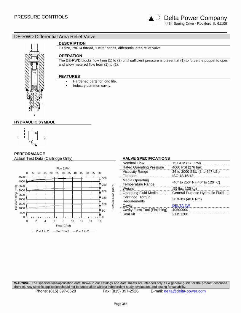
DE-RWD Differential Area Relief Valve
DESCRIPTION 10 size, 7/8-14 thread, “Delta” series, differential area relief valve. OPERATION The DE-RWD blocks flow from (1) to (2) until sufficient pressure is present at (1) to force the poppet to open and allow metered flow from (1) to (2). FEATURES
• Hardened parts for long life. • Industry common cavity.
HYDRAULIC SYMBOL
PERFORMANCE Actual Test Data (Cartridge Only) VALVE SPECIFICATIONS
Nominal Flow 15 GPM (57 LPM) Rated Operating Pressure 4000 PSI (276 bar) Viscosity Range 36 to 3000 SSU (3 to 647 cSt) Filtration ISO 18/16/13 Media Operating Temperature Range -40° to 250° F (-40° to 120° C)
Weight .55 lbs. (.25 kg) Operating Fluid Media General Purpose Hydraulic Fluid Cartridge Torque Requirements 30 ft-lbs (40.6 Nm)
Cavity DELTA 2W Cavity Form Tool (Finishing) 40500000
Seal Kit 21191200
0
500
1000
1500
2000
2500
3000
3500
4000
4500
0 2 4 6 8 10 12 14 16
Flow (GPM)
Pre
ssur
e D
rop
(PS
I)
0
50
100
150
200
250
300
0 5 10 15 20 25 30 35 40 45 50 55 60
Flow (LPM)
Pre
ssur
e D
rop
(BA
R)
Port 1 to 2 Port 1 to 2 Port 1 to 2
Page 356

PRESSURE CONTROLS Delta Power Company
4484 Boeing Drive - Rockford, IL 61109
WARNING: The specifications/application data shown in our catalogs and data sheets are intended only as a general guide for the product described (herein). Any specific application should not be undertaken without independent study, evaluation, and testing for suitability.
Phone: (815) 397-6628 Fax: (815) 397-2526 E-mail: [email protected]
DIMENSIONS
ORDERING INFORMATION DE-RWD - - -
OPTIONS BODIES Note: Aluminum NOT durability rated for
External Adj. W/Locknut, Buna 00 Blank Without Body 4000 PSI. Consult factory for options. External Adj. W/Locknut, Viton V0 N 3/8 NPTF Ports
Buna, Knob 0K S #8 SAE Ports Viton, Knob VK
Internally Adj. Buna 0I Internally Adj. Viton VI PRESSURE RANGE/SETTING
Tamper Proof, Buna 0T Ext./Int. Adjustment Tamper Proof, Viton VT 0500 100 – 1000 PSI
3000 100 – 3000 PSI 4000 3000 – 4000 PSI Tamper Proof Fill In 4 Digit Pressure Setting Example: 0500 – 500 PSI
Page 357

Page 358

PRESSURE CONTROLS Delta Power Company
4484 Boeing Drive - Rockford, IL 61109
WARNING: The specifications/application data shown in our catalogs and data sheets are intended only as a general guide for the product described (herein). Any specific application should not be undertaken without independent study, evaluation, and testing for suitability.
Phone: (815) 397-6628 Fax: (815) 397-2526 E-mail: [email protected]
Pilot Operated Relief Valves
GPM PSI LPM BAR MODEL PAGE 20 4000 76 276 DE-RVP 360 20 4000 76 276 HT-RVP 362
15 4000 57 276 DE-RVR 364
40 3500 151 241 SJ-RVR 366 15 4000 57 276 DE-RWP 368
40 5000 151 345 HE-RWP 370 15 4000 57 276 DE-RWR 372
Typical Schematic Typical application for the RVP and RWP is to protect pump or system. Typical application for the RWR and RVR, is to be used as counterbalance in a system where positive hydraulic locking is not required. In this schematic positive locking is done by using a P. O. check valve.
RWRRVR
RWPRVP
LOAD
LOAD
Page 359

PRESSURE CONTROLS Delta Power Company 4484 Boeing Drive - Rockford, IL 61109
WARNING: The specifications/application data shown in our catalogs and data sheets are intended only as a general guide for the product described (herein). Any specific application should not be undertaken without independent study, evaluation, and testing for suitability.
Phone: (815) 397-6628 Fax: (815) 397-2526 E-mail: [email protected]
DE-RVP Pilot Operated Relief Valve
DESCRIPTION 10 size, 7/8-14 thread, “Delta” series, pilot operated relief valve. OPERATION The DE-RVP blocks flow from (2) to (1) until sufficient pressure is present at (2) to force the pilot stage open, allowing the main stage to shift, opening (2) to (1). The cartridge offers smooth transition in response to load changes in common hydraulic circuits. FEATURES
• Hardened parts for long life. • Industry common cavity.
HYDRAULIC SYMBOL
PERFORMANCE Actual Test Data (Cartridge Only) VALVE SPECIFICATIONS
Nominal Flow 20 GPM (76 LPM) Rated Operating Pressure 4000 PSI (276 bar) Viscosity Range 36 to 3000 SSU (3 to 647 cSt) Filtration ISO 18/16/13 Media Operating Temperature Range -40° to 250° F (-40° to 120° C)
Weight .56 lbs. (.25 kg) Operating Fluid Media General Purpose Hydraulic Fluid Cartridge Torque Requirements 30 ft-lbs (40.6 Nm)
Cavity DELTA 2W Cavity Form Tool (Finishing) 40500000
Seal Kit 21191200
0
500
1000
1500
2000
2500
3000
0 5 10 15 20Flow (GPM)
Pre
ssur
e D
rop
(PS
I)
0
50
100
150
200
0 25 50 75Flow (LPM)
Pre
ssur
e D
rop
(BA
R)
Port 2 to 1 Port 2 to 1
Page 360
PRESSURE CONTROLS Delta Power Company 4484 Boeing Drive - Rockford, IL 61109
WARNING: The specifications/application data shown in our catalogs and data sheets are intended only as a general guide for the product described (herein). Any specific application should not be undertaken without independent study, evaluation, and testing for suitability.
Phone: (815) 397-6628 Fax: (815) 397-2526 E-mail: [email protected]
DIMENSIONS
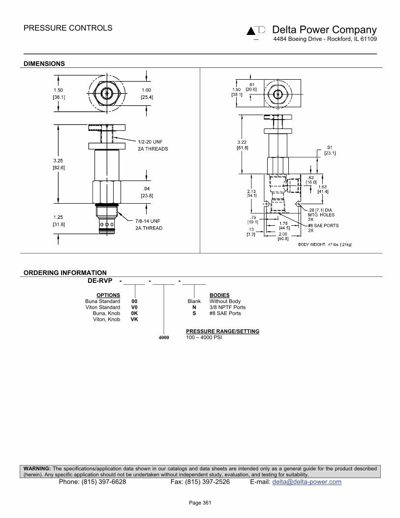
ORDERING INFORMATION DE-RVP - - -
OPTIONS BODIES
Buna Standard 00 Blank Without Body Viton Standard V0 N 3/8 NPTF Ports
Buna, Knob 0K S #8 SAE Ports Viton, Knob VK
PRESSURE RANGE/SETTING 4000 100 – 4000 PSI
Page 361

PRESSURE CONTROLS Delta Power Company
4484 Boeing Drive - Rockford, IL 61109
WARNING: The specifications/application data shown in our catalogs and data sheets are intended only as a general guide for the product described (herein). Any specific application should not be undertaken without independent study, evaluation, and testing for suitability.
Phone: (815) 397-6628 Fax: (815) 397-2526 E-mail: [email protected]
HT-RVP Pilot Operated Relief Valve
DESCRIPTION 12 size, 1 1/16-12 thread, “Tecnord” series, pilot operated relief valve. OPERATION The HT-RVP blocks flow from (2) to (1) until sufficient pressure is present at (2) to force the pilot stage off its seat, allowing the main stage spool to shift, opening (2) to (1). The cartridge offers smooth transition in response to load changes in common hydraulic circuits.
FEATURES • Hardened parts for long life. • Industry common cavity.
Undercut cavity recommended for circuits above 2500 PSI where flows go to 30 GPM.
HYDRAULIC SYMBOL VALVE SPECIFICATIONS Nominal Flow 20 GPM (76 LPM) Rated Operating Pressure 4000 PSI (276 bar) Viscosity Range 36 to 3000 SSU (3 to 647 cSt)
Filtration ISO 18/16/13
Media Operating Temperature Range -40° to 250° F (-40° to 120° C)
Weight 1.13 lbs. (.51 kg) Operating Fluid Media General Purpose Hydraulic Fluid
Cartridge Torque Requirements 70 ft-lbs (95 Nm)
Cavity TECNORD 2W PERFORMANCE Cavity Form Tool (Finishing) 40500032 Actual Test Data (Cartridge Only) Seal Kit 21191300
Standard cavity
0
500
1000
1500
2000
2500
3000
3500
4000
4500
0 5 10 15 20 25Flow (GPM)
Pre
ssur
e (P
SI)
0
50
100
150
200
250
300
0 20 40 60 80
Flow (LPM)
Pre
ssur
e (B
AR
)
Tank PSI Inlet PSI
Undercut Cavity
0500
10001500200025003000350040004500
0 5 10 15 20 25Flow (GPM)
Pre
ssur
e (P
SI)
0
50
100
150
200
250
300
0 20 40 60 80Flow (LPM)
Pre
ssur
e (B
AR
)
Tank PSI Inlet PSI
Page 362

PRESSURE CONTROLS Delta Power Company
4484 Boeing Drive - Rockford, IL 61109
WARNING: The specifications/application data shown in our catalogs and data sheets are intended only as a general guide for the product described (herein). Any specific application should not be undertaken without independent study, evaluation, and testing for suitability.
Phone: (815) 397-6628 Fax: (815) 397-2526 E-mail: [email protected]
MENSIONS
ORDERING INFORMATION HT-RVP - - -
OPTIONS BODIES
Buna Standard 00 Blank Without Body Viton Standard V0 S #12 SAE Ports
Buna, Knob 0K Viton, Knob VK
PRESSURE SETTING 5000 100 - 5000 PSI
Page 363

PRESSURE CONTROLS Delta Power Company 4484 Boeing Drive - Rockford, IL 61109
WARNING: The specifications/application data shown in our catalogs and data sheets are intended only as a general guide for the product described (herein). Any specific application should not be undertaken without independent study, evaluation, and testing for suitability.
Phone: (815) 397-6628 Fax: (815) 397-2526 E-mail: [email protected]
DE-RVR Pilot Operated Relief Valve, with Reverse Flow
DESCRIPTION 10 size, 7/8-14 thread, “Delta” series, pilot operated relief valve with reverse flow OPERATION The DE-RVR blocks flow from (2) to (1) until sufficient pressure is present at (2) to force the pilot stage open, allowing the main stage to shift, opening (2) to (1). The relief flow path is from (2) to (1). Free reverse flow, from (1) to (2), occurs when the pressure at (1) is at least 10 PSI (.7 bar) higher than at port (2). FEATURES
• Hardened parts for long life. • Industry common cavity.
HYDRAULIC SYMBOL
Consult Chart for flow capacity port 1 to 2
PERFORMANCE Actual Test Data (Cartridge Only) VALVE SPECIFICATIONS
Nominal Flow 15 GPM (57 LPM) Rated Operating Pressure 4000 PSI (276 bar) Viscosity Range 36 to 3000 SSU (3 to 647 cSt) Filtration ISO 18/16/13 Media Operating Temperature Range -40° to 250° F (-40° to 120° C)
Weight .56 lbs. (.25 kg) Operating Fluid Media General Purpose Hydraulic Fluid Cartridge Torque Requirements 30 ft-lbs (40.6 Nm)
Cavity DELTA 2W Cavity Form Tool (Finishing) 40500000
Seal Kit 21191200
0500
10001500200025003000350040004500
0 2 4 6 8 10 12 14 16Flow (GPM)
Pre
ssur
e D
rop
(PS
I)
0
50
100
150
200
250
300
0 5 10 15 20 25 30 35 40 45 50 55 60Flow (LPM)
Pre
ssur
e D
rop
(BA
R)
Port 2 to 1 Port 2 to 1 Port 1 to 2
Page 364
PRESSURE CONTROLS Delta Power Company 4484 Boeing Drive - Rockford, IL 61109
WARNING: The specifications/application data shown in our catalogs and data sheets are intended only as a general guide for the product described (herein). Any specific application should not be undertaken without independent study, evaluation, and testing for suitability.
Phone: (815) 397-6628 Fax: (815) 397-2526 E-mail: [email protected]
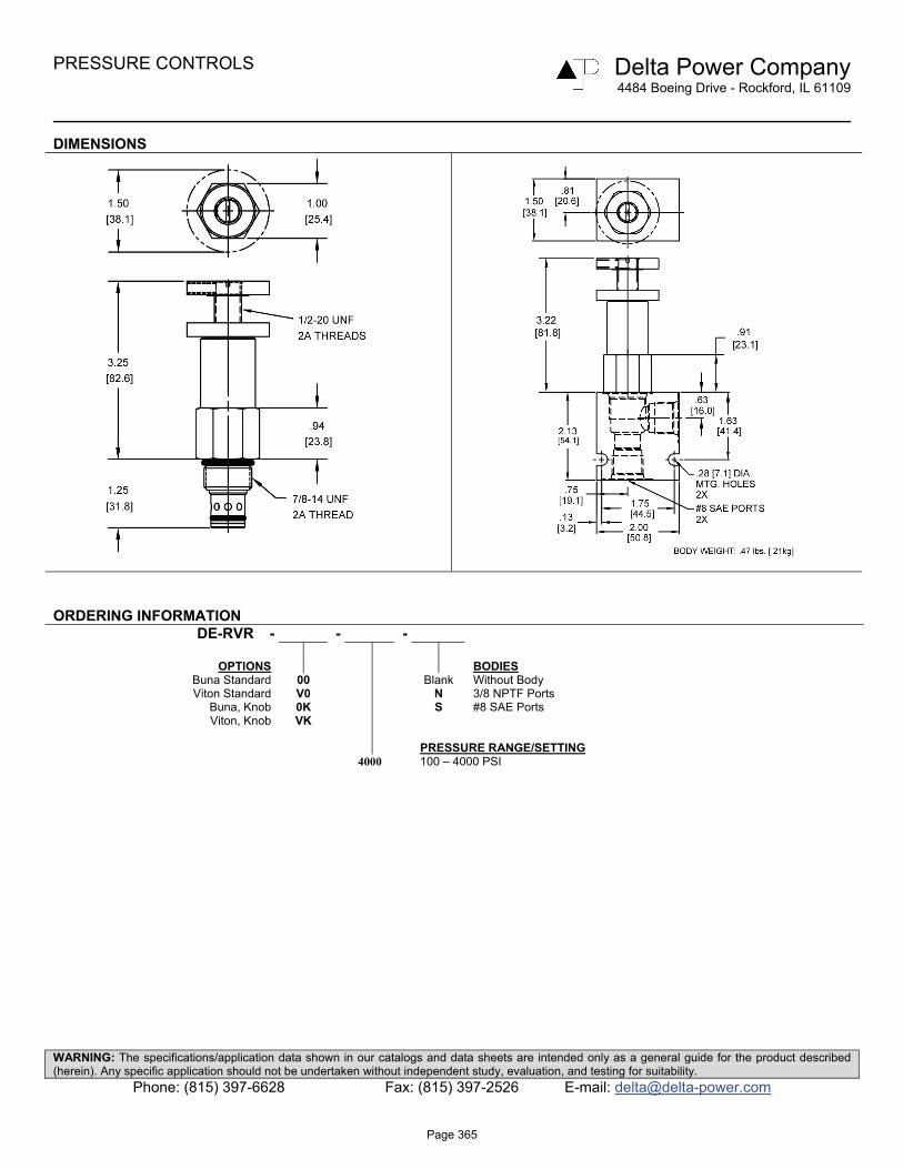
DIMENSIONS
ORDERING INFORMATION DE-RVR - - -
OPTIONS BODIES
Buna Standard 00 Blank Without Body Viton Standard V0 N 3/8 NPTF Ports
Buna, Knob 0K S #8 SAE Ports Viton, Knob VK
PRESSURE RANGE/SETTING 4000 100 – 4000 PSI
Page 365

PRESSURE CONTROLS Delta Power Company
4484 Boeing Drive - Rockford, IL 61109
WARNING: The specifications/application data shown in our catalogs and data sheets are intended only as a general guide for the product described (herein). Any specific application should not be undertaken without independent study, evaluation, and testing for suitability.
Phone: (815) 397-6628 Fax: (815) 397-2526 E-mail: [email protected]
SJ-RVR Pilot Operated Relief Valve, with Reverse Flow
DESCRIPTION 16 size, 1 5/16-12 thread, “Super” series, pilot operated relief valve with reverse flow. OPERATION The SJ-RVR blocks flow from (2) to (1) until sufficient pressure is present at (2) to force the pilot stage off its seat, allowing the main stage spool to shift, opening (2) to (1). The relief flow path is from (2) to (1). Reverse flow, from (1) to (2), occurs when the pressure at (1) is at least 30 PSI (2.1bar) higher then at port (2). The Cartridge offers smooth transition in response to load changes in common hydraulic circuits.
FEATURES
• Hardened parts for long life. • Industry common cavity.
HYDRAULIC SYMBOL VALVE SPECIFICATIONS Nominal Flow 40 GPM (151 LPM)
Rated Operating Pressure 3500 PSI (241 bar) Viscosity Range 36 to 3000 SSU (3 to 647 cSt)
Filtration ISO 18/16/13
Media Operating Temperature Range -40° to 250° F (-40° to 120° C)
Weight 1.13 lbs. (.51 kg) Operating Fluid Media General Purpose Hydraulic Fluid
Cartridge Torque Requirements
90 ft-lbs (122 Nm)
Cavity SUPER 2W PERFORMANCE Cavity Form Tool (Finishing) 40500017 Actual Test Data (Cartridge Only) Seal Kit 21191400
Standard body
0
500
1000
1500
2000
2500
3000
3500
0 5 10 15 20 25 30 35Flow (GPM)
Pre
ssur
e D
rop
(PS
I)
0
50
100
150
200
0 25 50 75 100 125
Flow (LPM)
Pre
ssur
e D
rop
(BA
R)
Tank PSI Inlet PSI
Standard Body
0
500
1000
1500
2000
2500
0 5 10 15 20 25 30
Flow (GPM)
Pre
ssur
e D
rop
(PS
I)
0
50
100
150
0 25 50 75 100 125
Flow (LPM)
Pre
ssur
e D
rop
(BA
R)
Port 2 to 1 Port 2 to 1 Port 1 to 2
Page 366

PRESSURE CONTROLS Delta Power Company
4484 Boeing Drive - Rockford, IL 61109
WARNING: The specifications/application data shown in our catalogs and data sheets are intended only as a general guide for the product described (herein). Any specific application should not be undertaken without independent study, evaluation, and testing for suitability.
Phone: (815) 397-6628 Fax: (815) 397-2526 E-mail: [email protected]
DIMENSIONS
ORDERING INFORMATION SJ-RVR - - -
OPTIONS BODIES
Buna Standard 00 Blank Without Body Viton Standard V0 N 3/4 NPTF Ports
Buna, Knob 0K S #12 SAE Ports Viton, Knob VK
Buna, Internal Adjust 0I PRESSURE SETTING Viton, Internal Adjust VI 3500 500 - 3500 PSI Buna, Tamper Proof 0T Viton, Tamper Proof VT TAMPER PROOF (fill in 4 digit pressure setting)
Example 0500 = 500 PSI
Page 367

PRESSURE CONTROLS Delta Power Company 4484 Boeing Drive - Rockford, IL 61109
WARNING: The specifications/application data shown in our catalogs and data sheets are intended only as a general guide for the product described (herein). Any specific application should not be undertaken without independent study, evaluation, and testing for suitability.
Phone: (815) 397-6628 Fax: (815) 397-2526 E-mail: [email protected]
DE-RWP Pilot Operated Relief Valve
DESCRIPTION 10 size, 7/8-14 thread, “Delta” series, pilot operated relief valve. OPERATION The DE-RWP blocks flow from (2) to (1) until sufficient pressure is present at (2) to force the pilot stage open, allowing the main stage to shift, opening (2) to (1). FEATURES
• Hardened parts for long life. • Industry common cavity.
HYDRAULIC SYMBOL
PERFORMANCE Actual Test Data (Cartridge Only) VALVE SPECIFICATIONS
Nominal Flow 15 GPM (57 LPM) Rated Operating Pressure 4000 PSI (276 bar) Viscosity Range 36 to 3000 SSU (3 to 647 cSt) Filtration ISO 18/16/13 Media Operating Temperature Range -40° to 250° F (-40° to 120° C)
Weight .53 lbs. (.24 kg) Operating Fluid Media General Purpose Hydraulic Fluid Cartridge Torque Requirements 30 ft-lbs (40.6 Nm)
Cavity DELTA 2W Cavity Form Tool (Finishing) 40500000
Seal Kit 21191200
0
500
1000
1500
2000
2500
3000
0 5 10 15 20Flow (GPM)
Pre
ssur
e D
rop
(PS
I)
0
50
100
150
200
0 25 50 75Flow (LPM)
Pre
ssur
e D
rop
(BA
R)
Port 2 to 1 Port 2 to 1
Page 368

PRESSURE CONTROLS Delta Power Company 4484 Boeing Drive - Rockford, IL 61109
WARNING: The specifications/application data shown in our catalogs and data sheets are intended only as a general guide for the product described (herein). Any specific application should not be undertaken without independent study, evaluation, and testing for suitability.
Phone: (815) 397-6628 Fax: (815) 397-2526 E-mail: [email protected]
DIMENSIONS
ORDERING INFORMATION DE-RWP - - -
OPTIONS BODIES
Buna Standard 00 Blank Without Body Viton Standard V0 N 3/8 NPTF Ports
Buna, Knob 0K S #8 SAE Ports Viton, Knob VK
Internally Adj. Buna 0I Internally Adj. Viton VI PRESSURE RANGE/SETTING Tamper Proof Buna 0T 4000 1000 – 4000 PSI Tamper Proof Viton VT
Tamper Proof Fill in 4 Digit Pressure Setting Example: 0500 – 500 PSI
Page 369

PRESSURE CONTROLS Delta Power Company
4484 Boeing Drive - Rockford, IL 61109
WARNING: The specifications/application data shown in our catalogs and data sheets are intended only as a general guide for the product described (herein). Any specific application should not be undertaken without independent study, evaluation, and testing for suitability.
Phone: (815) 397-6628 Fax: (815) 397-2526 E-mail: [email protected]
HE-RWP Rapid Response, Pilot Operated Relief Valve
DESCRIPTION “High Pressure, High Flow, Rapid Response, 10 size, 7/8-14 thread, “Delta” series, pilot operated relief valve. OPERATION The HE-RWP blocks flow from (2) to (1) until sufficient pressure is present at (2) to force the pilot stage open, allowing the main stage to shift, opening (2) to (1). FEATURES
• High pressure valve • Hardened parts for long life. • Industry common cavity. • Rapid response to sudden pressure application • Excellent regulation of pressure with flow (low override)
HYDRAULIC SYMBOL
This is a rapid response, high pressure relief valve with excellent high flow regulation. (Consult factory for higher flow capacity cavity option)
PERFORMANCE Actual Test Data (Cartridge Only) VALVE SPECIFICATIONS
Nominal Flow 40 GPM (151 LPM) Rated Operating Pressure 5000 PSI (345 bar) Viscosity Range 36 to 3000 SSU (3 to 647 cSt) Filtration ISO 18/16/13 Media Operating Temperature Range -40° to 250° F (-40° to 120° C)
Weight .53 lbs. (.24 kg) Operating Fluid Media General Purpose Hydraulic Fluid Cartridge Torque Requirements 30 ft-lbs (40.6 Nm)
Cavity DELTA 2W Cavity Form Tool (Finishing) 40500000
Seal Kit 21191200
HERWP/Pressure drop vs flow
0
1000
2000
3000
4000
5000
0 10 20 30 40
Flow (gpm)
Pre
ssu
re D
rop
(p
si)
0
60
120
180
240
300
0 37 74 111 148
Flow (lpm)
Pre
ssu
re D
rop
(b
ar)
HERWP at 4000 psi HERWP at 2000psi
Page 370

PRESSURE CONTROLS Delta Power Company
4484 Boeing Drive - Rockford, IL 61109
WARNING: The specifications/application data shown in our catalogs and data sheets are intended only as a general guide for the product described (herein). Any specific application should not be undertaken without independent study, evaluation, and testing for suitability.
Phone: (815) 397-6628 Fax: (815) 397-2526 E-mail: [email protected]
DIMENSIONS
ORDERING INFORMATION HE-RWP - - -
OPTIONS BODIES
Buna Standard 00 Consult Factory Viton Standard V0 WARNING
Buna, Knob 0K DO NOT USE ALUMINUM BODY Viton, Knob VK HIGH PRESSURE (5000 PSI) PRODUCT
Internally Adj. Buna 0I Internally Adj. Viton VI PRESSURE RANGE/SETTING Tamper Proof Buna 0T 5000 1000 – 5000 PSI Tamper Proof Viton VT
Tamper Proof Fill in 4 Digit Pressure Setting Example: 1500 – 1500 PSI
Page 371

PRESSURE CONTROLS Delta Power Company 4484 Boeing Drive - Rockford, IL 61109
WARNING: The specifications/application data shown in our catalogs and data sheets are intended only as a general guide for the product described (herein). Any specific application should not be undertaken without independent study, evaluation, and testing for suitability.
Phone: (815) 397-6628 Fax: (815) 397-2526 E-mail: [email protected]
DE-RWR Pilot Operated Relief Valve, with Reverse Flow
DESCRIPTION 10 size, 7/8-14 thread, “Delta” series, pilot operated relief valve with reverse flow. OPERATION The DE-RWR blocks flow from (2) to (1) until sufficient pressure is present at (2) to force the pilot stage open, and allow metered flow from (2) to (1). The relief flow path is from (2) to (1). Free reverse flow, from (1) to (2), occurs when the pressure at (1) is at least 10 PSI (.7 bar) higher than at port (2). FEATURES
• Hardened parts for long life. • Industry common cavity.
HYDRAULIC SYMBOL
Consult chart for flow capacity (1) to (2).
PERFORMANCE Actual Test Data (Cartridge Only) VALVE SPECIFICATIONS
Nominal Flow 15 GPM (57 LPM) Rated Operating Pressure 4000 PSI (276 bar) Viscosity Range 36 to 3000 SSU (3 to 647 cSt) Filtration ISO 18/16/13 Media Operating Temperature Range -40° to 250° F (-40° to 120° C)
Weight .53 lbs. (.24 kg) Operating Fluid Media General Purpose Hydraulic Fluid Cartridge Torque Requirements 30 ft-lbs (40.6 Nm)
Cavity DELTA 2W Cavity Form Tool (Finishing) 40500000
Seal Kit 21191200
Standard Body
0
500
1000
1500
2000
2500
3000
0 5 10 15 20Flow (GPM)
Pre
ssur
e D
rop
(PS
I)
0
50
100
150
200
0 25 50 75Flow (LPM)
Pre
ssur
e D
rop
(BA
R)
Port 2 to 1 Port 2 to 1 Port 1 to 2
Page 372
PRESSURE CONTROLS Delta Power Company 4484 Boeing Drive - Rockford, IL 61109
WARNING: The specifications/application data shown in our catalogs and data sheets are intended only as a general guide for the product described (herein). Any specific application should not be undertaken without independent study, evaluation, and testing for suitability.
Phone: (815) 397-6628 Fax: (815) 397-2526 E-mail: [email protected]
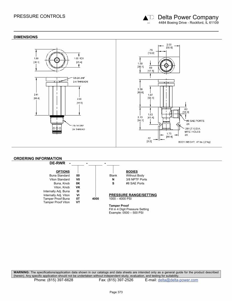
DIMENSIONS
ORDERING INFORMATION DE-RWR - - -
OPTIONS BODIES
Buna Standard 00 Blank Without Body Viton Standard V0 N 3/8 NPTF Ports
Buna, Knob 0K S #8 SAE Ports Viton, Knob VK
Internally Adj. Buna 0I Internally Adj. Viton VI PRESSURE RANGE/SETTING Tamper Proof Buna 0T 4000 1000 – 4000 PSI Tamper Proof Viton VT
Tamper Proof Fill in 4 Digit Pressure Setting Example: 0500 – 500 PSI
Page 373

Page 374

PRESSURE CONTROLS Delta Power Company 4484 Boeing Drive - Rockford, IL 61109
WARNING: The specifications/application data shown in our catalogs and data sheets are intended only as a general guide for the product described (herein). Any specific application should not be undertaken without independent study, evaluation, and testing for suitability.
Phone: (815) 397-6628 Fax: (815) 397-2526 E-mail: [email protected]
Crossover Relief Valves
GPM PSI LPM BAR MODEL PAGE 15 4000 57 276 DE-RVB 376
15 4000 57 276 DE-RVC 378
Typical Schematic Typical application for the RVC is in a series circuit where a load on motor #2 causes back pressure on motor #1 and relief valve #1. Vent in port 2 of RV 1 allows spring to maintain proper load on motor #1 even though back pressure is present. Port 2 pressure into spring chamber to offset back pressure. Vent at port 2 causes .2 GPM flow from port 2 to port 1. Typical application for the RVB is in a parallel circuit where the load on motor #2 does not cause back pressure on motor #1. Relief valve maintains differential pressure across motor because one side of motor always goes to tank.
1 2
#1RVB
#2#1RVC
1 2
#2
Page 375

PRESSURE CONTROLS Delta Power Company 4484 Boeing Drive - Rockford, IL 61109
WARNING: The specifications/application data shown in our catalogs and data sheets are intended only as a general guide for the product described (herein). Any specific application should not be undertaken without independent study, evaluation, and testing for suitability.
Phone: (815) 397-6628 Fax: (815) 397-2526 E-mail: [email protected]
DE-RVB Crossover Relief Valve, For Parallel Circuits
DESCRIPTION 10 size, 7/8-14 thread, “Delta” series, crossover relief valve for parallel circuit applications OPERATION The DE-RVB is a direct-acting, cross over relief valve. When pressure at either port exceeds the nominal setting value, flow will be diverted to the opposite port. Back pressure at either port will affect the nominal setting of the opposite port on a 1:1 basis. For correlation purposes, pre-set value will be measured at port (2). Pressure at port (1) will not vary more than ±300 PSI from the port (2) value. The cartridge offers smooth transition in response to load changes in common hydraulic circuits. FEATURES
• Hardened parts for long life. • Industry common cavity.
HYDRAULIC SYMBOL Tamper Proof Adjustable
The DE-RVB is designed for parallel circuit applications. For series circuits, use DE-RVC
PERFORMANCE Actual Test Data (Cartridge Only) VALVE SPECIFICATIONS
Nominal Flow 15 GPM (57 LPM) FROM (2) TO (1) 20 GPM (76 LPM) FROM (1) TO (2)
Rated Operating Pressure 4000 PSI (276 bar) Viscosity Range 36 to 3000 SSU (3 to 647 cSt) Filtration ISO 18/16/13 Media Operating Temperature Range -40° to 250° F (-40° to 120° C)
Weight .80 lbs. (.36 kg) Operating Fluid Media General Purpose Hydraulic Fluid Cartridge Torque Requirements 30 ft-lbs (40.6 Nm)
Cavity DELTA 2W Cavity Form Tool (Finishing) 40500000
Seal Kit 21191202
0
500
1000
1500
2000
2500
3000
3500
4000
4500
0 2 4 6 8 10 12 14 16Flow (GPM)
Pres
sure
Dro
p (P
SI)
0
50
100
150
200
250
300
0 5 10 15 20 25 30 35 40 45 50 55 60Flow (LPM)
Pres
sure
Dro
p (B
AR)
Port 1 to 2 Port 1 to 2 Port 1 to 2
Page 376

PRESSURE CONTROLS Delta Power Company 4484 Boeing Drive - Rockford, IL 61109
WARNING: The specifications/application data shown in our catalogs and data sheets are intended only as a general guide for the product described (herein). Any specific application should not be undertaken without independent study, evaluation, and testing for suitability.
Phone: (815) 397-6628 Fax: (815) 397-2526 E-mail: [email protected]
DIMENSIONS
ORDERING INFORMATION DE-RVB - - -
OPTIONS BODIES
Buna Standard 00 Blank Without Body Viton Standard V0 N 3/8 NPTF Ports
Buna, Knob 0K S #8 SAE Ports Viton, Knob VK
Buna, Internal Adjust 0I PRESSURE RANGE/SETTING Viton, Internal Adjust VI Ext./Int. Adjustable Buna, Tamper Proof 0T 0700 100 – 700 PSI Viton, Tamper Proof VT 1800 500 – 1800 PSI
4000 1000 – 4000 PSI Tamper Proof Fill in 4 Digit Pressure Setting Example: 0500 – 500 PSI
Page 377
PRESSURE CONTROLS Delta Power Company 4484 Boeing Drive - Rockford, IL 61109
WARNING: The specifications/application data shown in our catalogs and data sheets are intended only as a general guide for the product described (herein). Any specific application should not be undertaken without independent study, evaluation, and testing for suitability.
Phone: (815) 397-6628 Fax: (815) 397-2526 E-mail: [email protected]
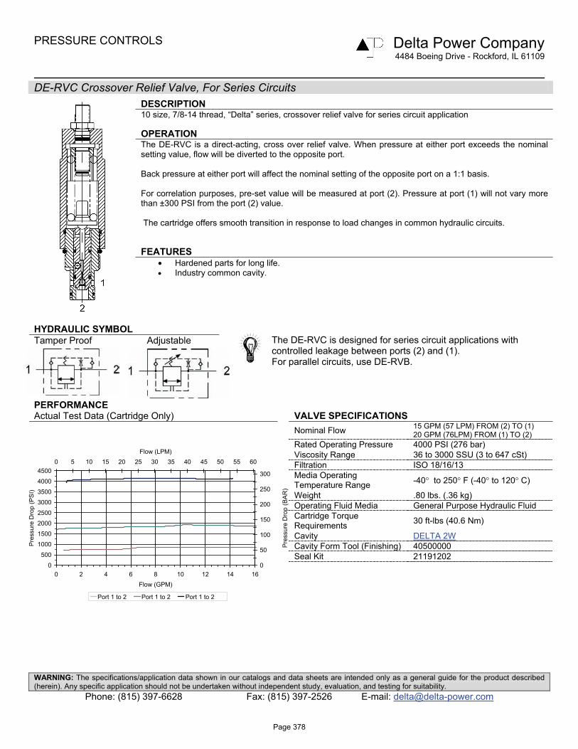
DE-RVC Crossover Relief Valve, For Series Circuits
DESCRIPTION 10 size, 7/8-14 thread, “Delta” series, crossover relief valve for series circuit application OPERATION The DE-RVC is a direct-acting, cross over relief valve. When pressure at either port exceeds the nominal setting value, flow will be diverted to the opposite port. Back pressure at either port will affect the nominal setting of the opposite port on a 1:1 basis. For correlation purposes, pre-set value will be measured at port (2). Pressure at port (1) will not vary more than ±300 PSI from the port (2) value. The cartridge offers smooth transition in response to load changes in common hydraulic circuits. FEATURES
• Hardened parts for long life. • Industry common cavity.
HYDRAULIC SYMBOL Tamper Proof Adjustable
The DE-RVC is designed for series circuit applications with controlled leakage between ports (2) and (1). For parallel circuits, use DE-RVB.
PERFORMANCE Actual Test Data (Cartridge Only) VALVE SPECIFICATIONS
Nominal Flow 15 GPM (57 LPM) FROM (2) TO (1) 20 GPM (76LPM) FROM (1) TO (2)
Rated Operating Pressure 4000 PSI (276 bar) Viscosity Range 36 to 3000 SSU (3 to 647 cSt) Filtration ISO 18/16/13 Media Operating Temperature Range -40° to 250° F (-40° to 120° C)
Weight .80 lbs. (.36 kg) Operating Fluid Media General Purpose Hydraulic Fluid Cartridge Torque Requirements 30 ft-lbs (40.6 Nm)
Cavity DELTA 2W Cavity Form Tool (Finishing) 40500000
Seal Kit 21191202
0
500
1000
1500
2000
2500
3000
3500
4000
4500
0 2 4 6 8 10 12 14 16Flow (GPM)
Pre
ssur
e D
rop
(PS
I)
0
50
100
150
200
250
300
0 5 10 15 20 25 30 35 40 45 50 55 60Flow (LPM)
Pre
ssur
e D
rop
(BA
R)
Port 1 to 2 Port 1 to 2 Port 1 to 2
Page 378

PRESSURE CONTROLS Delta Power Company 4484 Boeing Drive - Rockford, IL 61109
WARNING: The specifications/application data shown in our catalogs and data sheets are intended only as a general guide for the product described (herein). Any specific application should not be undertaken without independent study, evaluation, and testing for suitability.
Phone: (815) 397-6628 Fax: (815) 397-2526 E-mail: [email protected]
DIMENSIONS
ORDERING INFORMATION DE-RVC - - -
OPTIONS BODIES
Buna Standard 00 Blank Without Body Viton Standard V0 N 3/8 NPTF Ports
Buna, Knob 0K S #8 SAE Ports Viton, Knob VK
Buna, Internal Adjust 0I PRESSURE RANGE/SETTING Viton, Internal Adjust VI Ext./Int. Adjustable Buna, Tamper Proof 0T 0700 100 – 700 PSI Viton, Tamper Proof VT 1800 500 – 1800 PSI
4000 1000 – 4000 PSI Tamper Proof Fill in 4 Digit Pressure Setting Example: 0500 – 500 PSI
Page 379

Page 380
PRESSURE CONTROLS Delta Power Company 4484 Boeing Drive - Rockford, IL 61109
WARNING: The specifications/application data shown in our catalogs and data sheets are intended only as a general guide for the product described (herein). Any specific application should not be undertaken without independent study, evaluation, and testing for suitability.
Phone: (815) 397-6628 Fax: (815) 397-2526 E-mail: [email protected]
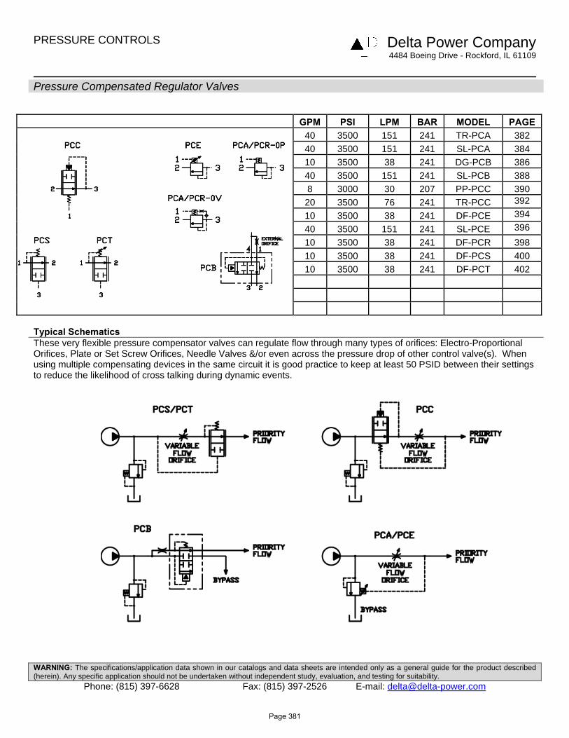
Pressure Compensated Regulator Valves
GPM PSI LPM BAR MODEL PAGE
40 3500 151 241 TR-PCA 382 40 3500 151 241 SL-PCA 384 10 3500 38 241 DG-PCB 386 40 3500 151 241 SL-PCB 388 8 3000 30 207 PP-PCC 390 20 3500 76 241 TR-PCC 39210 3500 38 241 DF-PCE 39440 3500 151 241 SL-PCE 39610 3500 38 241 DF-PCR 398 10 3500 38 241 DF-PCS 400 10 3500 38 241 DF-PCT 402
Typical Schematics These very flexible pressure compensator valves can regulate flow through many types of orifices: Electro-Proportional Orifices, Plate or Set Screw Orifices, Needle Valves &/or even across the pressure drop of other control valve(s). When using multiple compensating devices in the same circuit it is good practice to keep at least 50 PSID between their settings to reduce the likelihood of cross talking during dynamic events.
Page 381

PRESSURE CONTROLS Delta Power Company
4484 Boeing Drive - Rockford, IL 61109
WARNING: The specifications/application data shown in our catalogs and data sheets are intended only as a general guide for the product described (herein). Any specific application should not be undertaken without independent study, evaluation, and testing for suitability.
Phone: (815) 397-6628 Fax: (815) 397-2526 E-mail: [email protected]
TR-PCA Pressure Compensating Regulator Valve
DESCRIPTION 12 size, 1 1/16-12 thread, “Tecnord” series, pressure compensating regulator valve. OPERATION The TR-PCA-0P with an orifice between ports (3) and (1) maintains a constant flow rate from (3) regardless of load pressure changes in the system upstream of (3), or in the bypass leg at (2) as long as pressure at (2) is less than (1). The valve's spool maintains a constant differential pressure across an external orifice, thereby regulating the hydraulic flow rate across this external orifice. (see options table for pressure ranges) When used with an orifice as described above, it functions as a priority type regulator, delivering pump flow first to the external orifice, then bypassing excess to (2). All ports may be fully pressurized. The TR-PCA-0V with a dump valve and a pilot relief valve at (1) acts as main stage of a ventable relief valve. FEATURES
• Hardened parts for long life. • Industry common cavity.
HYDRAULIC SYMBOL
Can be used as a logic element. TR-PCA-0P is commonly used as a bypass flow regulator (90 and 150 PSI recommended). TR-PCA-0V is commonly used as the main stage of a ventable relief valve (50 and 90 PSI recommended).
PERFORMANCE Actual Test Data (Cartridge Only) VALVE SPECIFICATIONS
Nominal Flow 40 GPM (151 LPM) Rated Operating Pressure 3500 PSI (241 bar)
Seat Ratio Area of Pilot is equal to the area at Port (3)
Viscosity Range 36 to 3000 SSU (3 to 647 cSt) Filtration ISO 18/16/13 Media Operating Temperature Range -40° to 250° F (-40° to 120° C)
Weight .54 lbs. (.24 kg) Operating Fluid Media General Purpose Hydraulic Fluid Cartridge Torque Requirements 70 ft-lbs (95 Nm)
Cavity TECNORD 3W Cavity Form Tool (Finishing) 40500034
Seal Kit 21191306
0
50
100
150
200
250
300
350
0 5 10 15 20 25 30 35 40
Flow (GPM)
Pre
ssur
e @
Por
t 3 (
PS
I)
0
5
10
15
20
0 25 50 75 100 125 150
Flow (LPM)
Pre
ssur
e @
Por
t 3 (
BA
R)
Port 3 to 2 Port 3 to 2
Page 382

PRESSURE CONTROLS Delta Power Company
4484 Boeing Drive - Rockford, IL 61109
WARNING: The specifications/application data shown in our catalogs and data sheets are intended only as a general guide for the product described (herein). Any specific application should not be undertaken without independent study, evaluation, and testing for suitability.
Phone: (815) 397-6628 Fax: (815) 397-2526 E-mail: [email protected]
DIMENSIONS
ORDERING INFORMATION TR-PCA - - -
OPTIONS BODIES
Buna, Pilot to Close 0P Blank Without Body Buna, Vent to Open 0V S #10 SAE Ports Viton, Pilot to Close VP Viton, Vent to Open VV
∆∆∆∆ P SETTING @ 1 GPM with Pilot Vented 0020 20 PSI 0050 50 PSI 0090 90 PSI 0150 150 PSI 0230 230 PSI
Page 383

PRESSURE CONTROLS Delta Power Company
4484 Boeing Drive - Rockford, IL 61109
WARNING: The specifications/application data shown in our catalogs and data sheets are intended only as a general guide for the product described (herein). Any specific application should not be undertaken without independent study, evaluation, and testing for suitability.
Phone: (815) 397-6628 Fax: (815) 397-2526 E-mail: [email protected]
SL-PCA Pressure Compensating Regulator Valve
DESCRIPTION 16 size, 1 5/16-12 thread, “Super” series, pressure compensating regulator valve. OPERATION The SL-PCA-0P with an external orifice between ports (3) and (1) maintains a constant flow rate across the external orifice, regardless of load pressure changes in the system upstream of (3), or in the bypass leg at (2) as long as pressure at (2) is less than (1). The valve's spool maintains a constant differential pressure across the external orifice, thereby regulating the hydraulic flow rate across the external orifice. (see options table for pressure ranges) When used with an orifice as described above, it functions as a priority type regulator, delivering pump flow first to the external orifice, then bypassing excess to (2). All ports may be fully pressurized. The SL-PCA-0V with a dump valve and a pilot relief valve at (1) acts as main stage of a ventable relief valve. FEATURES
• Hardened parts for long life. • Industry common cavity.
HYDRAULIC SYMBOL
Can be used as a logic element.
SL-PCA-0P is commonly used as a bypass flow regulator (100 PSI recommended). SL-PCA-0V is commonly used as the main stage of a ventable relief valve (50 and 100 PSI recommended).
PERFORMANCE Actual Test Data (Cartridge Only) VALVE SPECIFICATIONS
Nominal Flow 40 GPM (151 LPM) Rated Operating Pressure 3500 PSI (241 bar)
Seat Ratio Initially area of Pilot is 1.2 times the area at Port (3), then 1:1
Viscosity Range 36 to 3000 SSU (3 to 647 cSt) Filtration ISO 18/16/13 Media Operating Temperature Range -40° to 250° F (-40° to 120° C)
Weight .70 lbs. (.32 kg) Operating Fluid Media General Purpose Hydraulic Fluid Cartridge Torque Requirements 90 ft-lbs (122 Nm)
Cavity SUPER 3WS Cavity Form Tool (Finishing) 40500021
Seal Kit 21191406
0
5 0
1 0 0
1 5 0
2 0 0
2 5 0
3 0 0
3 5 0
0 5 1 0 1 5 2 0 2 5 3 0 3 5 4 0F lo w (G P M )
Pre
ssur
e @
Por
t 3 (
PS
I)
0
5
1 0
1 5
2 0
0 2 5 5 0 7 5 1 0 0 1 2 5 1 5 0
F lo w (L P M )
Pre
ssur
e @
Por
t 3 (
BA
R)
P o r t 3 to 2 (U n d e rc u t C a v ity ) P o r t 3 to 2 (S ta n d a rd C a v ity )
0
50
100
150
200
250
300
350
400
0 5 10 15 20 25 30 35 40
F low (G PM )
Pre
ssur
e @
Por
t 3 (
PS
I)
0
5
10
15
20
25
0 25 50 75 100 125 150
F low (LPM )
Pre
ssur
e @
Por
t 3 (
BA
R)
Port 3 to 2 (U ndercut C avity) Port 3 to 2 (S tandard C avity)
Page 384

PRESSURE CONTROLS Delta Power Company
4484 Boeing Drive - Rockford, IL 61109
WARNING: The specifications/application data shown in our catalogs and data sheets are intended only as a general guide for the product described (herein). Any specific application should not be undertaken without independent study, evaluation, and testing for suitability.
Phone: (815) 397-6628 Fax: (815) 397-2526 E-mail: [email protected]
DIMENSIONS
ORDERING INFORMATION SL-PCA - - -
OPTIONS BODIES
Buna, Pilot to Close 0P Blank Without Body Buna, Vent to Open 0V S #12 SAE Ports Viton, Pilot to Close VP Viton, Vent to Open VV
Buna, Pilot to Close with Seals 0B ∆∆∆∆ P SETTING Buna, Vent to Open with Seals 0C @ 1 GPM with Pilot Vented Viton, Pilot to Close with Seals VB 0020 20 PSI Viton, Vent to Open with Seals VC 0050 50 PSI
0100 100 PSI 0150 150 PSI
Page 385

PRESSURE CONTROLS Delta Power Company
4484 Boeing Drive - Rockford, IL 61109
WARNING: The specifications/application data shown in our catalogs and data sheets are intended only as a general guide for the product described (herein). Any specific application should not be undertaken without independent study, evaluation, and testing for suitability.
Phone: (815) 397-6628 Fax: (815) 397-2526 E-mail: [email protected]
DG-PCB Pressure Compensating Valve, Restrictive Type With By-pass
DESCRIPTION 10 size, 7/8-14 thread, “Delta” series, pressure compensating valve, restrictive type with by-pass. OPERATION The DG-PCB allows pressure compensated or proportional flow from (1) to (2) regulated by the pressure differential across (1) and (4) with a bypass of (4) to (3). The spring chamber is constantly connected at (1). FEATURES
• Hardened parts for longer life. • Industry common cavity.
HYDRAULIC SYMBOL
DG-PCB is not intended for differential pressure more than 1500 PSI from (4) to (3). Consult Factory for abrupt pressure change applications that exceed 1500 PSI, for alternative products.
PERFORMANCE Actual Test Data (Cartridge Only with 150 PSI Spring) VALVE SPECIFICATIONS
Nominal Flow 10 GPM (38 LPM) Rated Operating Pressure 3500 PSI (241.3 bar) Typical Internal Leakage (150 SSU) 5 cu in/min (82 ml/min) per path
Viscosity Range 36 to 3000 SSU (3 to 647 cSt) Filtration ISO 18/16/13 Media Operating Temperature Range -40° to 250° F (-40° to 120° C)
Weight .38 lbs. (.17 kg) Operating Fluid Media General Purpose Hydraulic Fluid Cartridge Torque Requirements 30 ft-lbs (40.6 Nm)
Cavity DELTA 4W Cavity Form Tool (Finishing) 40500002
Seal Kit 21191214
10 gpm supply flow, .110" orifice, 150 psi spring15 gpm suply flow, .156" orifice, 150 psi spring
1500 psi load on port 3
0
2
4
6
8
10
0 500 1000 1500 2000 2500 3000Pressure @ Port 2 (PSI)
Reg
ulat
ed F
low
@
Por
t 2 (
GP
M)
0
5
10
15
20
25
30
35
0 50 100 150 200
Pressure @ Port 2 (BAR)
Reg
ulat
ed F
low
@
Por
t 2 (
LPM
)
.110" dia. orifice .156" dia. orifice
priority port 2 load: 1500-1700 psi, .156" dia orifice, 15 gpm supply not intended for differential pressure > 1500 psi port 4 to port 3
0
2
4
6
8
10
0 500 1000 1500 2000 2500 3000
Pressure @ Port 3 (PSI)
Flo
w (
GP
M)
05101520253035
0 50 100 150 200
Pressure @ Port 3 (BAR)
Flo
w (
LPM
)
Port 2 flow Port 3 flow
priority port 2 load: 1500-1700 psi, .110" dia orifice, 10 gpm supply not intended for differential pressure > 1500 psi port 4 to port 3
0
2
4
6
8
10
0 500 1000 1500 2000 2500 3000
Pressure @ Port 3 (PSI)
Flo
w (
GP
M)
05101520253035
0 50 100 150 200
Pressure @ Port 3 (BAR)F
low
(LP
M)
Port 2 flow Port 3 flow
Page 386

PRESSURE CONTROLS Delta Power Company
4484 Boeing Drive - Rockford, IL 61109
WARNING: The specifications/application data shown in our catalogs and data sheets are intended only as a general guide for the product described (herein). Any specific application should not be undertaken without independent study, evaluation, and testing for suitability.
Phone: (815) 397-6628 Fax: (815) 397-2526 E-mail: [email protected]
DIMENSIONS
ORDERING INFORMATION DG-PCB - - -
OPTIONS BODIES
Buna Standard 00 Blank Without Body Viton Standard V0 N 1/4 NPTF Ports
S #6 SAE Ports PRESSURE DIFFERENTIAL 0150 150 PSI 0250 250 PSI Differential Pressure Across External Controlling Orifice
Page 387

PRESSURE CONTROLS Delta Power Company 4484 Boeing Drive - Rockford, IL 61109
WARNING: The specifications/application data shown in our catalogs and data sheets are intended only as a general guide for the product described (herein). Any specific application should not be undertaken without independent study, evaluation, and testing for suitability.
Phone: (815) 397-6628 Fax: (815) 397-2526 E-mail: [email protected]
SL-PCB Pressure Compensating Regulator Valve
DESCRIPTION 16 size, 1 5/16-12 thread, “Super” series, pressure compensating regulator valve. OPERATION The SL-PCB-0P with an orifice between ports (3) and (1) maintains a constant flow rate from (3) regardless of load pressure changes in the system upstream of (3), or in the bypass leg at (2) as long as pressure at (2) is less than (1). The valve's spool maintains a constant differential pressure across a internal orifice, thereby regulating the hydraulic flow rate from across this external orifice. (see options table for pressure ranges) When used with an orifice as described above, it functions as a priority type regulator, delivering pump flow first to the external orifice, then bypassing excess to (2). All ports may be fully pressurized. The SL-PCB-0V with a dump valve and a pilot relief valve at (1) acts as main stage of a ventable relief valve. FEATURES
• Hardened parts for long life. • Industry common cavity.
HYDRAULIC SYMBOL
Can be used as a logic element.
SL-PCB-0P is commonly used as a bypass flow regulator (100 PSI recommended). SL-PCB-0V is commonly used as the main stage of a ventable relief valve (50 and 100 PSI recommended).
PERFORMANCE Actual Test Data (Cartridge Only) VALVE SPECIFICATIONS
Nominal Flow 40 GPM (151 LPM) Rated Operating Pressure 3500 PSI (241 bar)
Seat Ratio Initially area of Pilot is 1.5 times the area at Port (3), then 1:1
Viscosity Range 36 to 3000 SSU (3 to 647 cSt) Filtration ISO 18/16/13 Media Operating Temperature Range -40° to 250° F (-40° to 120° C)
Weight .71 lbs. (.32 kg) Operating Fluid Media General Purpose Hydraulic Fluid Cartridge Torque Requirements 90 ft-lbs (122 Nm)
Cavity SUPER 3WS Cavity Form Tool (Finishing) 40500017 Seal Kit 21191406
0
5 0
1 0 0
1 5 0
2 0 0
2 5 0
0 5 1 0 1 5 2 0 2 5 3 0 3 5 4 0F lo w (G P M )
Pres
sure
@ P
ort 3
(PSI
)
0
5
1 0
1 5
0 2 5 5 0 7 5 1 0 0 1 2 5 1 5 0
F lo w (L P M )
Pres
sure
@ P
ort 3
(BAR
)
P o r t 3 to 2 (U n d e rc u t C a v ity ) P o r t 3 to 2 (S ta n d a rd C a v ity )
0
50
100
150
200
250
300
350
0 5 10 15 20 25 30 35 40Flow (G PM )
Pres
sure
@ P
ort 3
(PSI
)
0
5
10
15
20
0 25 50 75 100 125 150
Flow (LPM )
Pres
sure
@ P
ort 3
(BAR
)
Port 3 to 2 (Undercut Cavity) Port 3 to 2 (S tandard Cavity)
Page 388

PRESSURE CONTROLS Delta Power Company 4484 Boeing Drive - Rockford, IL 61109
WARNING: The specifications/application data shown in our catalogs and data sheets are intended only as a general guide for the product described (herein). Any specific application should not be undertaken without independent study, evaluation, and testing for suitability.
Phone: (815) 397-6628 Fax: (815) 397-2526 E-mail: [email protected]
DIMENSIONS
ORDERING INFORMATION SL-PCB - - -
OPTIONS BODIES
Buna, Pilot to Close 0P Blank Without Body Buna, Vent to Open 0V S #12 SAE Ports Viton, Pilot to Close VP Viton, Vent to Open VV
Buna, Pilot to Close with Seals 0B ∆ P SETTING Buna, Vent to Open with Seals 0C @ 1 GPM with Pilot Vented Viton, Pilot to Close with Seals VB 0020 20 PSI Viton, Vent to Open with Seals VC 0050 50 PSI
0100 100 PSI 0150 150 PSI ± 20%
Page 389

PRESSURE CONTROLS Delta Power Company
4484 Boeing Drive - Rockford, IL 61109
WARNING: The specifications/application data shown in our catalogs and data sheets are intended only as a general guide for the product described (herein). Any specific application should not be undertaken without independent study, evaluation, and testing for suitability.
Phone: (815) 397-6628 Fax: (815) 397-2526 E-mail: [email protected]
PP-PCC Fixed Pressure Compensating Regulator Valve - Restrictive Type
DESCRIPTION 8 size, 3/4-16 thread, “Power” series, pressure compensating regulator valve (restrictive type). OPERATION The PP-PCC-00 with an external orifice beyond port (3) and sensed by port (1) maintains a constant flow rate from (3) regardless of load pressure changes in the system downstream of (3), or in the inlet at (2) as long as pressure at (3) is above (1) by more then spring setting chosen and pump supply is in excess of demand. The valve's spool maintains a constant differential pressure across an external orifice, thereby regulating the hydraulic flow rate across this external orifice. (see options table for pressure ranges) When used with an orifice as described above, it functions as a restrictive type regulator, delivering pump flow through the external orifice. All ports may be fully pressurized. FEATURES
• Hardened parts for long life. • Industry common cavity.
HYDRAULIC SYMBOL
Can be used as a logic element Fixed setting pressure reducing valve. For adjustable setting see PP-PCD. PP-PCC-00-0100 is recommended for regulated flows up to 4.0 GPM only. PP-PCC-00-0220 is recommended for regulated flows up to 8.0 GPM. For fixed pressure reducing/relieving valve see PP-PCP
PERFORMANCE Actual Test Data (Cartridge Only) VALVE SPECIFICATIONS
Nominal Flow 8 GPM (30 LPM) Rated Operating Pressure 3000 PSI (207 bar)
Ratio Area of Pilot is equal to the area at Port (3)
Viscosity Range 36 to 3000 SSU (3 to 647 cSt) Filtration ISO 18/16/13 Media Operating Temperature Range -40° to 250° F (-40° to 120° C)
Weight .25 lbs. (.11 kg) Operating Fluid Media General Purpose Hydraulic Fluid Cartridge Torque Requirements 25 ft-lbs (34 Nm)
Cavity POWER 3W Cavity Form Tool (Finishing) 40500024
Seal Kit 21191111
Regulated Flow vs Inlet Pressure
0123456789
0 500 1000 1500 2000 2500 3000
Inlet Pressure (PSI)
Reg
ula
ted
Flo
w (
GP
M)
048121620242832
0 34 68 102 136 170 204
Inlet Pressure (bar)
Reg
ula
ted
Flo
w (
lpm
)
2 GPM 4 GPM 6 GPM 8 GPM
Page 390
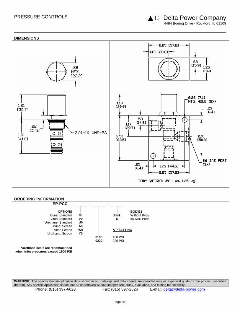
PRESSURE CONTROLS Delta Power Company
4484 Boeing Drive - Rockford, IL 61109
WARNING: The specifications/application data shown in our catalogs and data sheets are intended only as a general guide for the product described (herein). Any specific application should not be undertaken without independent study, evaluation, and testing for suitability.
Phone: (815) 397-6628 Fax: (815) 397-2526 E-mail: [email protected]
DIMENSIONS
ORDERING INFORMATION PP-PCC - - -
OPTIONS BODIES
Buna, Standard 00 Blank Without Body Viton, Standard V0 S #6 SAE Ports
*Urethane, Standard U0 Buna, Screen A0 Viton Screen W0 ∆∆∆∆ P SETTING
Urethane, Screen Y0 0100 100 PSI 0220 220 PSI
*Urethane seals are recommended when inlet pressures exceed 1500 PSI
Page 391

PRESSURE CONTROLS Delta Power Company
4484 Boeing Drive - Rockford, IL 61109
WARNING: The specifications/application data shown in our catalogs and data sheets are intended only as a general guide for the product described (herein). Any specific application should not be undertaken without independent study, evaluation, and testing for suitability.
Phone: (815) 397-6628 Fax: (815) 397-2526 E-mail: [email protected]
TR-PCC Pressure Compensating Regulator Valve – Restrictive Type
DESCRIPTION 12 size, 1 1/16-12 thread, “Tecnord” series, pressure compensating regulator valve (restrictive type) OPERATION The TR-PCC with an external orifice beyond port (3) and sensed by port (1) maintains a constant flow rate from (3) regardless of load pressure changes in the system downstream of (3), or in the inlet at (2) as long as pressure at (3) is greater than (1) by more than spring setting chosen and pump supply is in excess of demand. The valve's spool maintains a constant differential pressure across an external orifice, thereby regulating the hydraulic flow rate across this external orifice. (see table for pressure ranges) When used with an orifice as described above, it functions as a restrictive type regulator, delivering pump flow through the external orifice. All ports may be fully pressurized. FEATURES
• Hardened parts for long life. • Industry common cavity.
HYDRAULIC SYMBOL
Can be used as a logic element. Fixed setting pressure reducing valve. For adjustable setting see TR-PCD.
PERFORMANCE Actual Test Data (Cartridge Only) VALVE SPECIFICATIONS
Nominal Flow 20 GPM (75.5 LPM) Rated Operating Pressure 3500 PSI (241 bar)
Seat Ratio Area of Pilot is equal to the area at Port (3)
Viscosity Range 36 to 3000 SSU (3 to 647 cSt) Filtration ISO 18/16/13 Media Operating Temperature Range -40° to 250° F (-40° to 120° C)
Weight .54 lbs. (.24 kg) Operating Fluid Media General Purpose Hydraulic Fluid Cartridge Torque Requirements 70 ft-lbs (95 Nm)
Cavity TECNORD 3WS Cavity Form Tool (Finishing) 40500033
Regulated Flow vs Load Pressure at Port 1
0
4
8
12
16
20
0 500 1000 1500 2000 2500 3000Load Pressure at Port 1 (PSI)
Reg
ula
ted
Flo
w (
GP
M)
0
25
50
75
0 34 68 102 136 170 204Load Pressure at Port 1 (BAR)
Reg
ula
ted
Flo
w (
LP
M)
10gpm 14gpm 5 gpm
Seal Kit 21191306
Page 392

PRESSURE CONTROLS Delta Power Company
4484 Boeing Drive - Rockford, IL 61109
WARNING: The specifications/application data shown in our catalogs and data sheets are intended only as a general guide for the product described (herein). Any specific application should not be undertaken without independent study, evaluation, and testing for suitability.
Phone: (815) 397-6628 Fax: (815) 397-2526 E-mail: [email protected]
DIMENSIONS
ORDERING INFORMATION TR-PCC - - -
OPTIONS BODIES
Buna 00 Blank Without Body Viton V0 S #10 SAE Ports
∆∆∆∆ P SETTING @ 1 GPM with Pilot Vented 0150 150 PSI 0300 300 PSI
Page 393

PRESSURE CONTROLS Delta Power Company
4484 Boeing Drive - Rockford, IL 61109
WARNING: The specifications/application data shown in our catalogs and data sheets are intended only as a general guide for the product described (herein). Any specific application should not be undertaken without independent study, evaluation, and testing for suitability.
Phone: (815) 397-6628 Fax: (815) 397-2526 E-mail: [email protected]
DF-PCE Adjustable Pressure Compensating Valve, Bypass Type
DESCRIPTION 10 size, 7/8-14 thread, “Delta” series, spring adjustable pressure compensating valve, bypass type. OPERATION The DF-PCE with an external orifice in parallel with ports (3) and (1) maintains a constant flow rate across the external orifice, regardless of load pressure changes in the system upstream of (3), or in the bypass leg at (2) as long as pressure at (2) is greater than (1). The valve's spool maintains a constant differential pressure across an external orifice, thereby regulating the hydraulic flow rate across this external orifice. (see table for pressure ranges) When used with an orifice as described above, it functions as a bypass type regulator, delivering pump flow through the external orifice. FEATURES
• Hardened parts for long life. • Industry common cavity.
HYDRAULIC SYMBOL
Can be used as an adjustable logic element. Great as an adjustable pressure setting regulation device in brake, transmission & cooling systems, because the spring chamber is separately drained, the outlet can be used for lower pressure functions. For fixed version see DF-PCR-0P. For higher spring differential pressure ranges consult factory
PERFORMANCE Actual Test Data (Cartridge Only) VALVE SPECIFICATIONS
Nominal Flow 10 GPM (38 LPM) Rated Operating Pressure 3500 PSI (241 bar)
Seat Ratio Area of Pilot is equal to the area at Port (3)
Viscosity Range 36 to 3000 SSU (3 to 647 cSt) Filtration ISO 18/16/13 Media Operating Temperature Range -40° to 250° F (-40° to 120° C)
Weight .52 lbs. (.23 kg) Operating Fluid Media General Purpose Hydraulic Fluid Cartridge Torque Requirements 30 ft-lbs (40.6 Nm)
Cavity DELTA 3W Cavity Form Tool (Finishing) 40500001
Seal Kit 21191210
300 psi setting /Regulated Flow vs Inlet Pressure
0
2
4
6
8
10
0 500 1000 1500 2000 2500 3000Inlet Pressure (PSI)
Reg
ula
ted
Flo
w (
gp
m)
05101520253035
0 50 100 150 200Inlet Pressure (bar)
Reg
ula
ted
Flo
w (
lpm
)
4 gpm 6 gpm 8 gpm 2 gpm
Page 394

PRESSURE CONTROLS Delta Power Company
4484 Boeing Drive - Rockford, IL 61109
WARNING: The specifications/application data shown in our catalogs and data sheets are intended only as a general guide for the product described (herein). Any specific application should not be undertaken without independent study, evaluation, and testing for suitability.
Phone: (815) 397-6628 Fax: (815) 397-2526 E-mail: [email protected]
DIMENSIONS
ORDERING INFORMATION DF-PCE - - -
OPTIONS BODIES
Buna Standard 00 Blank Without Body Viton Standard V0 N 1/4 NPTF Ports
Buna, Knob 0K S #6 SAE Ports Viton, Knob VK
Buna, Internal Adjust 0I PRESSURE RANGE Viton, Internal Adjust VI 0300 100-300 PSI Buna, Tamper Proof 0T Viton, Tamper Proof VT Differential Pressure Across
External Controlling Orifice TAMPER PROOF Fill in 4 Digit Pressure Setting Example: 0200 = 200 PSI
Page 395

PRESSURE CONTROLS Delta Power Company
4484 Boeing Drive - Rockford, IL 61109
WARNING: The specifications/application data shown in our catalogs and data sheets are intended only as a general guide for the product described (herein). Any specific application should not be undertaken without independent study, evaluation, and testing for suitability.
Phone: (815) 397-6628 Fax: (815) 397-2526 E-mail: [email protected]
SL-PCE Adjustable Pressure Compensating Regulator Valve
DESCRIPTION 16 size, 1 5/16-12 thread, “Super” series, pressure compensating regulator valve. OPERATION The SL-PCE with an external orifice in parallel with ports (3) and (1) maintains a constant flow rate across the external orifice, regardless of load pressure changes in the system upstream of (3), or in the bypass leg at (2) as long as pressure at (2) is less than (1). The valve's spool maintains a constant differential pressure across the external orifice, thereby regulating the hydraulic flow rate across the external orifice. (see options table for pressure ranges) When used with an orifice as described above, it functions as a priority type regulator, delivering pump flow first to the external orifice, then bypassing excess to (2). All ports may be fully pressurized. FEATURES
• Hardened parts for long life. • Industry common cavity.
HYDRAULIC SYMBOL
Can be used as an adjustable logic element. Great as an adjustable pressure setting regulation device in brake, transmission & cooling systems. Because the spring chamber is separately drained, the outlet flow can be used for lower pressure functions. For fixed version see SL-PCA-0P. For higher spring differential pressure ranges consult factory.
PERFORMANCE Actual Test Data (Cartridge Only) VALVE SPECIFICATIONS
Nominal Flow 40 GPM (151 LPM) Rated Operating Pressure 3500 PSI (241 bar)
Seat Ratio Area of pilot is equal to the area at Port (3)
Viscosity Range 36 to 3000 SSU (3 to 647 cSt) Filtration ISO 18/16/13 Media Operating Temperature Range -40° to 250° F (-40° to 120° C)
Weight 1.15 Lbs. (.52 kg) Operating Fluid Media General Purpose Hydraulic Fluid Cartridge Torque Requirements 90 ft-lbs (122 Nm)
Cavity SUPER 3WS Cavity Form Tool (Finishing) 40500021
Seal Kit 21191406 0
50
100
150
200
250
300
350
0 5 10 15 20 25 30
Flow (GPM)
Pre
ssu
re D
rop
(P
SI)
0
3
6
9
12
15
18
21
24
0 10 20 30 40 50 60 70 80 90 100 110
Flow (LPM)
Pre
ssu
re d
rop
(B
AR
)
Port 3 to 2 Port 3 to 2 Port 3 to 2
Page 396

PRESSURE CONTROLS Delta Power Company
4484 Boeing Drive - Rockford, IL 61109
WARNING: The specifications/application data shown in our catalogs and data sheets are intended only as a general guide for the product described (herein). Any specific application should not be undertaken without independent study, evaluation, and testing for suitability.
Phone: (815) 397-6628 Fax: (815) 397-2526 E-mail: [email protected]
DIMENSIONS
ORDERING INFORMATION SL-PCE - - -
OPTIONS BODIES
Buna, Standard 00 Blank Without Body Viton, Standard V0 S #12 SAE Ports
Buna, Knob 0K Viton, Knob VK
Buna, Internal Adjust 0I Viton, Internal Adjust VI PRESSURE RANGE/SETTING Buna, Tamper Proof 0T 0300 50 – 300 PSI Viton, Tamper Proof VT
TAMPERPROOF (fill in 4 digit pressure setting) Example: 0200 = 200 PSI
Page 397

PRESSURE CONTROLS Delta Power Company 4484 Boeing Drive - Rockford, IL 61109
WARNING: The specifications/application data shown in our catalogs and data sheets are intended only as a general guide for the product described (herein). Any specific application should not be undertaken without independent study, evaluation, and testing for suitability.
Phone: (815) 397-6628 Fax: (815) 397-2526 E-mail: [email protected]
DF-PCR Pressure Compensating Regulator Valve
DESCRIPTION 10 size, 7/8-14 thread, “Delta” series, pressure compensating regulator valve. OPERATION The DF-PCR-0P with an orifice between ports (3) and (1) maintains a constant flow rate from (3) regardless of load pressure changes in the system upstream of (3), or in the bypass leg at (2) as long as pressure at (2) is less than (1). The valve's spool maintains a constant differential pressure across an external orifice, thereby regulating the hydraulic flow rate from (3) to (2). (see options table for pressure ranges) When used with an orifice as described above, as a priority type regulator, delivering pump flow first to (3), then bypassing excess to (2). All ports may be fully pressurized. The DF-PCR-0V with a dump valve and a pilot relief valve at (1) acts as main stage of a ventable relief valve. FEATURES
• Hardened parts for long life. • Industry common cavity.
HYDRAULIC SYMBOL
Can be used as a logic element. DF-PCR-0P is commonly used as a bypass flow regulator (80 PSI recommended). DF-PCR-0V is commonly used as the main stage of a ventable relief valve (40 and 80 PSI recommended).
PERFORMANCE Actual Test Data (Cartridge Only) VALVE SPECIFICATIONS
Nominal Flow 10 GPM (38 LPM) Rated Operating Pressure 3500 PSI (241 bar)
Seat Ratio Area of Pilot is equal to the area at Port (3)
Viscosity Range 36 to 3000 SSU (3 to 647 cSt) Filtration ISO 18/16/13 Media Operating Temperature Range -40° to 250° F (-40° to 120° C)
Weight .19 lbs. (.08 kg) Operating Fluid Media General Purpose Hydraulic Fluid Cartridge Torque Requirements 30 ft-lbs (40.6 Nm)
Cavity DELTA 3W Cavity Form Tool (Finishing) 40500001
Seal Kit 21191206
0
50
100
150
200
250
0 2 4 6 8 10Flow (GPM)
Pres
sure
@ P
ort 3
(PSI
)
0
5
10
15
0 5 10 15 20 25 30 35Flow (LPM)
Pres
sure
@ P
ort 3
(BAR
)
Port 3 to 2 Port 3 to 2
Page 398
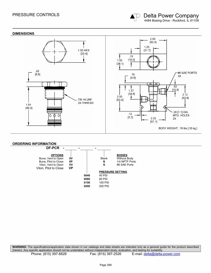
PRESSURE CONTROLS Delta Power Company 4484 Boeing Drive - Rockford, IL 61109
WARNING: The specifications/application data shown in our catalogs and data sheets are intended only as a general guide for the product described (herein). Any specific application should not be undertaken without independent study, evaluation, and testing for suitability.
Phone: (815) 397-6628 Fax: (815) 397-2526 E-mail: [email protected]
DIMENSIONS
ORDERING INFORMATION DF-PCR - - -
OPTIONS BODIES
Buna, Vent to Open 0V Blank Without Body Buna, Pilot to Close 0P N 1/4 NPTF Ports Viton, Vent to Open VV S #6 SAE Ports
Viton, Pilot to Close VP PRESSURE SETTING 0040 40 PSI 0080 80 PSI 0150 150 PSI 0200 200 PSI
Page 399

PRESSURE CONTROLS Delta Power Company 4484 Boeing Drive - Rockford, IL 61109
WARNING: The specifications/application data shown in our catalogs and data sheets are intended only as a general guide for the product described (herein). Any specific application should not be undertaken without independent study, evaluation, and testing for suitability.
Phone: (815) 397-6628 Fax: (815) 397-2526 E-mail: [email protected]
DF-PCS Pressure Compensating Valve, Restrictive Type
DESCRIPTION 10 size, 7/8-14 thread, “Delta” series, pressure compensating valve, restrictive type. OPERATION The DF-PCS allows pressure compensated flow from (1) to (2) regulated by the pressure present at (3). The spring chamber is constantly vented at (1). FEATURES
• Hardened parts for long life. • Industry common cavity.
HYDRAULIC SYMBOL
Pressure compensator for flow control, typically used with an external orifice inline with port (1). Port (3) should sense upstream pressure of orifice.
PERFORMANCE Actual Test Data (Cartridge Only) VALVE SPECIFICATIONS
Nominal Flow 10 GPM (38 LPM) Rated Operating Pressure 3500 PSI (241 bar) Typical Internal Leakage (150 SSU) 5 cu in/min (82 ml/min) per path
Viscosity Range 36 to 3000 SSU (3 to 647 cSt) Filtration ISO 18/16/13 Media Operating Temperature Range -40° to 250° F (-40° to 120° C)
Weight .35 lbs. (.16 kg) Operating Fluid Media General Purpose Hydraulic Fluid Cartridge Torque Requirements 30 ft-lbs (40.6 Nm)
Cavity DELTA 3W Cavity Form Tool (Finishing) 40500001
Seal Kit 21191210
0
2
4
6
8
10
0 500 1000 1500 2000 2500 3000Pressure @ Port 2 (PSI)
Flow
(GP
M)
0
5
10
15
20
25
30
35
0 50 100 150 200Pressure @ Port 2 (BAR)
Flow
(LP
M)
.110" dia. orifice .156" dia. orifice
Page 400

PRESSURE CONTROLS Delta Power Company 4484 Boeing Drive - Rockford, IL 61109
WARNING: The specifications/application data shown in our catalogs and data sheets are intended only as a general guide for the product described (herein). Any specific application should not be undertaken without independent study, evaluation, and testing for suitability.
Phone: (815) 397-6628 Fax: (815) 397-2526 E-mail: [email protected]
DIMENSIONS
ORDERING INFORMATION DF-PCS - - -
OPTIONS BODIES
Buna Standard 00 Blank Without Body Viton Standard V0 N 1/4 NPTF Ports
S #6 SAE Ports PRESSURE DIFFERENTIAL 0150 150 PSI 0450 450 PSI Differential Pressure Across External Controlling Orifice
Page 401

PRESSURE CONTROLS Delta Power Company
4484 Boeing Drive - Rockford, IL 61109
WARNING: The specifications/application data shown in our catalogs and data sheets are intended only as a general guide for the product described (herein). Any specific application should not be undertaken without independent study, evaluation, and testing for suitability.
Phone: (815) 397-6628 Fax: (815) 397-2526 E-mail: [email protected]
DF-PCT Adjustable Pressure Compensating Valve, Restrictive Type
DESCRIPTION 10 size, 7/8-14 thread, “Delta” series, pressure compensating valve, restrictive type. OPERATION The DF-PCT with an external orifice in front of port (1) allows pressure compensated flow from (1) to (2), regulated by the pressure present at (3). The spring chamber is constantly vented at (1). FEATURES
• Hardened parts for long life. • Industry common cavity.
HYDRAULIC SYMBOL
Can be used as an adjustable logic element. For fixed version see DF-PCS.
For higher spring differential pressure ranges consult factory.
PERFORMANCE Actual Test Data (Cartridge Only) VALVE SPECIFICATIONS
Nominal Flow 10 GPM (38 LPM) Rated Operating Pressure 3500 PSI (241 bar) Typical Internal Leakage (150 SSU) 5 cu in/min (82 ml/min) per path
Viscosity Range 36 to 3000 SSU (3 to 647 cSt) Filtration ISO 18/16/13 Media Operating Temperature Range -40° to 250° F (-40° to 120° C)
Weight .60 lbs. (.27 kg) Operating Fluid Media General Purpose Hydraulic Fluid Cartridge Torque Requirements 30 ft-lbs (40.6 Nm)
Cavity DELTA 3W Cavity Form Tool (Finishing) 40500001
300 PSI setting, Regulated Flow vs Inlet Pressure
0123456789
0 500 1000 1500 2000 2500 3000
Inlet Pressure (PSI)
Reg
ula
ted
Flo
w (
GP
M)
048121620242832
0 34 68 102 136 170 204
Inlet Pressure (bar)
Reg
ula
ted
Flo
w (
lpm
)
4 GPM 8 GPM Seal Kit 21191210
Page 402

PRESSURE CONTROLS Delta Power Company
4484 Boeing Drive - Rockford, IL 61109
WARNING: The specifications/application data shown in our catalogs and data sheets are intended only as a general guide for the product described (herein). Any specific application should not be undertaken without independent study, evaluation, and testing for suitability.
Phone: (815) 397-6628 Fax: (815) 397-2526 E-mail: [email protected]
DIMENSIONS
ORDERING INFORMATION DF-PCT - - -
OPTIONS BODIES
Buna Standard 00 Blank Without Body Viton Standard V0 N 1/4 NPTF Ports
Buna, Knob 0K S #6 SAE Ports Viton, Knob VK
Buna, Internal Adjust 0I PRESSURE RANGE Viton, Internal Adjust VI 0300 50-300 PSI Buna, Tamper Proof 0T Viton, Tamper Proof VT Differential Pressure Across
External Controlling Orifice TAMPER PROOF Fill in 4 Digit Pressure Setting Example: 0200 = 200 PSI
Page 403

Page 404
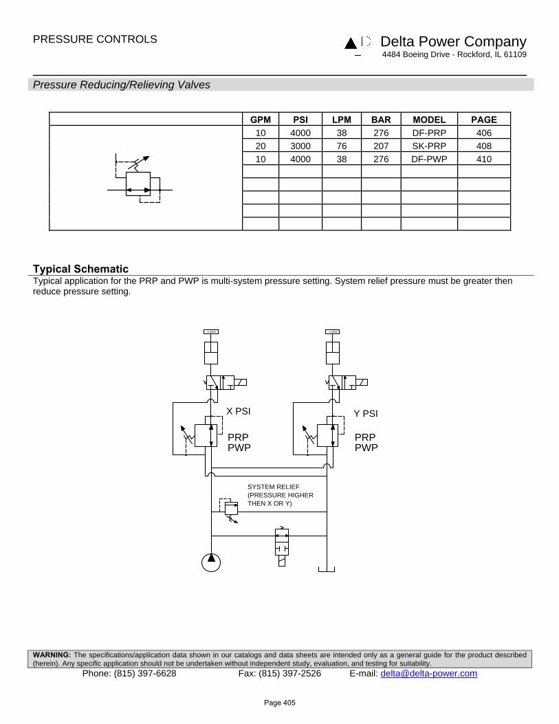
PRESSURE CONTROLS Delta Power Company 4484 Boeing Drive - Rockford, IL 61109
WARNING: The specifications/application data shown in our catalogs and data sheets are intended only as a general guide for the product described (herein). Any specific application should not be undertaken without independent study, evaluation, and testing for suitability.
Phone: (815) 397-6628 Fax: (815) 397-2526 E-mail: [email protected]
Pressure Reducing/Relieving Valves
GPM PSI LPM BAR MODEL PAGE 10 4000 38 276 DF-PRP 406
20 3000 76 207 SK-PRP 408 10 4000 38 276 DF-PWP 410
Typical Schematic Typical application for the PRP and PWP is multi-system pressure setting. System relief pressure must be greater then reduce pressure setting.
X PSI
PRP
LOAD
Y PSI
PRPPWP PWP
SYSTEM RELIEF(PRESSURE HIGHERTHEN X OR Y)
LOAD
Page 405

PRESSURE CONTROLS Delta Power Company 4484 Boeing Drive - Rockford, IL 61109
WARNING: The specifications/application data shown in our catalogs and data sheets are intended only as a general guide for the product described (herein). Any specific application should not be undertaken without independent study, evaluation, and testing for suitability.
Phone: (815) 397-6628 Fax: (815) 397-2526 E-mail: [email protected]
DF-PRP Pilot Operated, Pressure Reducing, Relieving Valve
DESCRIPTION 10 size, 7/8-14 thread, “Delta” series, pilot operated, pressure reducing, relieving valve OPERATION The DF-PRP in its steady state, allows flow to pass from (2) to (3), with the spring chamber constantly drained at (1). When a pre-determined pressure is reached at (3), the spool shifts to restrict input flow at (2), thereby reducing (restricting) flow. If valve and pressure at port (3) exceeds setting, spool shift to open passage at port (1), thereby regulating pressure at port (3) by relieving excess flow. The cartridge offers smooth transition in response to load changes in common hydraulic circuits. FEATURES
• Hardened parts for long life. • Industry common cavity.
HYDRAULIC SYMBOL VALVE SPECIFICATIONS Nominal Flow 10 GPM (38 LPM) Rated Operating Pressure 3000 PSI (207 bar) Viscosity Range 36 to 3000 SSU (3 to 647 cSt) Filtration ISO 18/16/13
Media Operating Temperature Range -40° to 250° F (-40° to 120° C)
Weight .59 lbs. (.27 kg)
Operating Fluid Media General Purpose Hydraulic Fluid
Cartridge Torque Requirements 30 ft-lbs (40.6 Nm)
Cavity DELTA 3W PERFORMANCE Cavity Form Tool (Finishing) 40500001 Actual Test Data (Cartridge Only) Seal Kit 21191206
0
500
1000
1500
2000
2500
0 2 4 6 8 10Flow (GPM)
Pre
ssur
e D
rop
(PS
I)
0
50
100
150
0 5 10 15 20 25 30 35Flow (LPM)
Pre
ssur
e D
rop
(BA
R)
Port 2 to 3 Port 3 to 1
0
500
1000
1500
2000
2500
0 2 4 6 8 10Flow (GPM)
Reg
ulat
ed P
ress
ure
(PS
I)
0
50
100
150
0 5 10 15 20 25 30 35Flow (LPM)
Reg
ulat
ed P
ress
ure
(BA
R)
Port 2 to 3 Port 2 to 3
Page 406
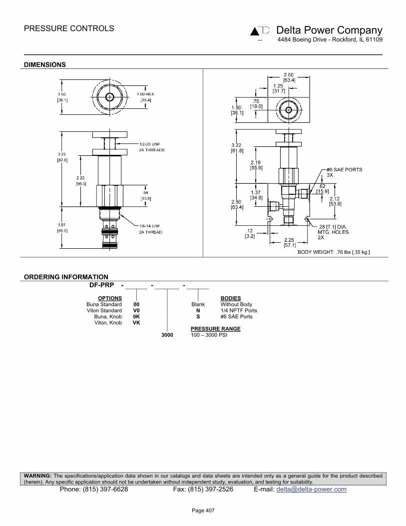
PRESSURE CONTROLS Delta Power Company 4484 Boeing Drive - Rockford, IL 61109
WARNING: The specifications/application data shown in our catalogs and data sheets are intended only as a general guide for the product described (herein). Any specific application should not be undertaken without independent study, evaluation, and testing for suitability.
Phone: (815) 397-6628 Fax: (815) 397-2526 E-mail: [email protected]
DIMENSIONS
ORDERING INFORMATION DF-PRP - - -
OPTIONS BODIES
Buna Standard 00 Blank Without Body Viton Standard V0 N 1/4 NPTF Ports
Buna, Knob 0K S #6 SAE Ports Viton, Knob VK
PRESSURE RANGE 3000 100 – 3000 PSI
Page 407

PRESSURE CONTROLS Delta Power Company 4484 Boeing Drive - Rockford, IL 61109
WARNING: The specifications/application data shown in our catalogs and data sheets are intended only as a general guide for the product described (herein). Any specific application should not be undertaken without independent study, evaluation, and testing for suitability.
Phone: (815) 397-6628 Fax: (815) 397-2526 E-mail: [email protected]
SK-PRP Pilot Operated Pressure Reducing, Relieving Valve
DESCRIPTION 16 size, 1 5/16-12 thread, “Super” series, pilot operated pressure reducing, relieving valve OPERATION The SK-PRP in its steady state, allows flow to pass from (2) to (3), with the spring chamber constantly drained at (1). When a pre-determined pressure is reached at (3), the spool shifts to restrict input flow at (2), thereby reducing (restricting) flow. If the valve and pressure at port (3) exceeds setting, spool shifts to open passage at port (1), thereby regulating pressure at (3) by relieving excess flow. The cartridge offers smooth transition in response to load changes in common hydraulic circuits.
FEATURES
• Hardened parts for long life. • Industry common cavity.
HYDRAULIC SYMBOL
PERFORMANCE Actual Test Data (Cartridge Only) VALVE SPECIFICATIONS
Nominal Flow 20 GPM (76 LPM) Rated Operating Pressure 500-3000 PSI (34-207 bar) Viscosity Range 36 to 3000 SSU (3 to 647 cSt) Filtration ISO 18/16/13 Media Operating Temperature Range -40° to 250° F (-40° to 120° C)
Weight 1.28 lbs. (.58 kg) Operating Fluid Media General Purpose Hydraulic Fluid Cartridge Torque Requirements 90 ft-lbs (122 Nm)
Cavity SUPER 3W Cavity Form Tool (Finishing) 40500018
Seal Kit 21191406
0
500
1000
1500
0 5 10 15 20Flow (GPM)
Pre
ssur
e D
rop
(PS
I)
0
50
100
0 25 50 75Flow (LPM)
Pre
ssur
e D
rop
(BA
R)
Port 2 to 3 Port 3 to 1 (valve set @ 1000 psi)
0
500
1000
1500
2000
2500
0 5 10 15 20Flow (GPM)
Pre
ssur
e D
rop
(PS
I)
0
50
100
150
0 25 50 75Flow (LPM)
Pre
ssur
e D
rop
(BA
R)
Port 2 to 3 Port 2 to 3
Page 408

PRESSURE CONTROLS Delta Power Company 4484 Boeing Drive - Rockford, IL 61109
WARNING: The specifications/application data shown in our catalogs and data sheets are intended only as a general guide for the product described (herein). Any specific application should not be undertaken without independent study, evaluation, and testing for suitability.
Phone: (815) 397-6628 Fax: (815) 397-2526 E-mail: [email protected]
DIMENSIONS
ORDERING INFORMATION SK-PRP - - -
OPTIONS BODIES
Buna Standard 00 Blank Without Body Viton Standard V0 S #12 SAE Ports
Buna, Knob 0K Viton, Knob VK
Buna, Internal Adjust 0I PRESSURE RANGE/SETTING Viton, Internal Adjust VI Ext./Int. Adjustable Buna, Tamper Proof 0T 3000 500 – 3000 PSI Viton, Tamper Proof VT
Tamper Proof Fill in 4 digit pressure setting
Example: 0500 – 500 PSI
Page 409

PRESSURE CONTROLS Delta Power Company 4484 Boeing Drive - Rockford, IL 61109
WARNING: The specifications/application data shown in our catalogs and data sheets are intended only as a general guide for the product described (herein). Any specific application should not be undertaken without independent study, evaluation, and testing for suitability.
Phone: (815) 397-6628 Fax: (815) 397-2526 E-mail: [email protected]
DF-PWP Pilot Operated Pressure Reducing, Relieving Valve
DESCRIPTION 10 size, 7/8-14 thread, “Delta” series, pilot operated pressure reducing, relieving valve OPERATION The DF-PWP in its steady state, allows flow to pass from (2) to (3), with the spring chamber constantly drained at (1). When a pre-determined pressure is reached at (3), the spool shifts to restrict input flow at (2), thereby reducing (restricting) flow. If valve and pressure at port (3) exceeds setting, spool shifts to open passage at port (1), thereby regulating pressure at port (3) by relieving excess flow. The cartridge offers smooth transition in response to load changes in common hydraulic circuits. FEATURES
• Hardened parts for long life. • Industry common cavity.
HYDRAULIC SYMBOL VALVE SPECIFICATIONS Nominal Flow 10 GPM (38 LPM) Rated Operating Pressure 4000 PSI (276 bar) Viscosity Range 36 to 3000 SSU (3 to 647 cSt) Filtration ISO 18/16/13 Media Operating Temperature Range -40° to 250° F (-40° to 120° C)
Weight .57 lbs. (.26 kg)
Operating Fluid Media General Purpose Hydraulic Fluid
Cartridge Torque Requirements 30 ft-lbs (40.6 Nm)
Cavity DELTA 3W PERFORMANCE Cavity Form Tool (Finishing) 40500001 Actual Test Data (Cartridge Only) Seal Kit 21191206
0
500
1000
1500
2000
2500
0 2 4 6 8 10Flow (GPM)
Pre
ssur
e D
rop
(PS
I)
0
50
100
150
0 5 10 15 20 25 30 35Flow (LPM)
Pre
ssur
e D
rop
(BA
R)
Port 2 to 3 Port 3 to 1
0
500
1000
1500
2000
2500
0 2 4 6 8 10Flow (GPM)
Reg
ulat
ed P
ress
ure
(PS
I)
0
50
100
150
0 5 10 15 20 25 30 35Flow (LPM)
Reg
ulat
ed P
ress
ure
(BA
R)
Port 2 to 3 Port 2 to 3
Page 410

PRESSURE CONTROLS Delta Power Company 4484 Boeing Drive - Rockford, IL 61109
WARNING: The specifications/application data shown in our catalogs and data sheets are intended only as a general guide for the product described (herein). Any specific application should not be undertaken without independent study, evaluation, and testing for suitability.
Phone: (815) 397-6628 Fax: (815) 397-2526 E-mail: [email protected]
DIMENSIONS
ORDERING INFORMATION DF-PWP - - -
OPTIONS BODIES
Buna Standard 00 Blank Without Body Viton Standard V0 N 1/4 NPTF Ports
Buna, Knob 0K S #6 SAE Ports Viton, Knob VK
Internally Adj. Buna 0I PRESSURE RANGE/SETTING Internally Adj. Viton VI Ext./Int. Adjustable Tamper Proof Buna 0T 4000 100 – 4000 PSI Tamper Proof Viton VT
Tamper Proof Fill in 4 Digit Pressure Setting Example: 0500 – 500 PSI
Page 411

Page 412

PRESSURE CONTROLS Delta Power Company 4484 Boeing Drive - Rockford, IL 61109
WARNING: The specifications/application data shown in our catalogs and data sheets are intended only as a general guide for the product described (herein). Any specific application should not be undertaken without independent study, evaluation, and testing for suitability.
Phone: (815) 397-6628 Fax: (815) 397-2526 E-mail: [email protected]
Sequence Valves
GPM PSI LPM BAR MODEL PAGE 10 3000 38 207 DG-PSA 414
10 3000 38 207 DG-PSC 416 10 3000 38 207 DG-PSI 418 10 3000 38 207 DG-PSO 420 12 3000 45 207 DG-PSS 422 10 3000 38 207 DG-PTC 424 10 3000 38 207 DG-PTO 426 10 3000 38 207 DF-PWE 428 8 3000 30 207 DF-PWI 430 40 3500 151 241 SL-PWA 432 40 3500 151 241 SL-PWB 434
Typical Schematic Typical application for the PSO or PSC sequence valve is for a high/low application like a log splitter where the spring chamber can be vented externally (spring chamber pressure directly adds to the pilot pressure required to shift the valve). Typical application for the PWI sequence valve is for controlling the lip on a dock leveler. Typical application for the PWE sequence valve is for a high/low pump in a positive traction circuit where the valve automatically shifts to low speed high torque mode. Typical application for the PSI sequence valve is when starting against load where the spring chamber can be vented externally (spring chamber pressure directly adds to the pilot pressure required to shift the valve). Typical application for the PSA sequence valve is a hydraulic brake release of a spring loaded single acting cylinder. Typical application for the PSS hot oil shuttle is to divert fluid from the low pressure side of a closed loop hydrostatic transmission for cooling or filtering.
Page 413

PRESSURE CONTROLS Delta Power Company 4484 Boeing Drive - Rockford, IL 61109
WARNING: The specifications/application data shown in our catalogs and data sheets are intended only as a general guide for the product described (herein). Any specific application should not be undertaken without independent study, evaluation, and testing for suitability.
Phone: (815) 397-6628 Fax: (815) 397-2526 E-mail: [email protected]
DG-PSA Sequence Valve, 4 Way Normally Closed, External Pilot
DESCRIPTION 10 size, 7/8-14 thread, “Delta” series, 4 way external pilot sequence valve. OPERATION The DG-PSA in neutral (un-piloted), allows flow between (1) and (2) bi-directionally, while blocking at (3). The spring chamber is constantly vented at (1). On attainment of a predetermined pressure at (4), the cartridge shifts to close (1) to (2), while opening (2) to (3). Note that the backpressure value at (1) must be added to the selected pressure setting to determine pilot pressure necessary to open valve. FEATURES
• Optional spring ranges to 1500 PSI (103 bar). • Hardened parts for long life. • Industry common cavity.
HYDRAULIC SYMBOL
.030 to .060 diameter orifice recommended beneath port (4).
PERFORMANCE Actual Test Data (Cartridge Only) VALVE SPECIFICATIONS
Nominal Flow 10 GPM (38 LTR/M) Rated Operating Pressure 3000 PSI (207 bar) Typical Internal Leakage (150 SSU) 5 cu in/min (82 ml/min)
Viscosity Range 36 to 3000 SSU (3 to 647 cSt) Filtration ISO 18/16/13 Media Operating Temperature Range -40° to 250° F (-40° to 120° C)
Weight .63 lbs. (.28 kg) Operating Fluid Media General Purpose Hydraulic Fluid Cartridge Torque Requirements 30 ft-lbs (40.6 Nm)
Cavity DELTA 4W Cavity Form Tool (Finishing) 40500002 Seal Kit 21191214
0
50
100
150
200
0 2 4 6 8 10 12Flow (GPM)
Pres
sure
Dro
p (P
SI)
0
5
10
0 10 20 30 40Flow (LPM)
Pres
sure
Dro
p (B
AR
)
Port 2 to 3 Port 2 to 1
Page 414

PRESSURE CONTROLS Delta Power Company 4484 Boeing Drive - Rockford, IL 61109
WARNING: The specifications/application data shown in our catalogs and data sheets are intended only as a general guide for the product described (herein). Any specific application should not be undertaken without independent study, evaluation, and testing for suitability.
Phone: (815) 397-6628 Fax: (815) 397-2526 E-mail: [email protected]
DIMENSIONS
ORDERING INFORMATION DG-PSA - - -
OPTIONS BODIES
Buna Standard 00 Blank Without Body Viton Standard V0 N 1/4 NPTF Ports
Buna, Knob 0K S #6 SAE Ports Viton Knob VK
Buna, Internal Adjust 0I Viton, Internal Adjust VI PRESSURE RANGE Buna, Tamper Proof 0T 0425 50-425 PSI Viton, Tamper Proof VT 1500 425-1500 PSI
TAMPER PROOF Fill in 4 Digit Pressure Setting Example: 0500-500PSI
Page 415
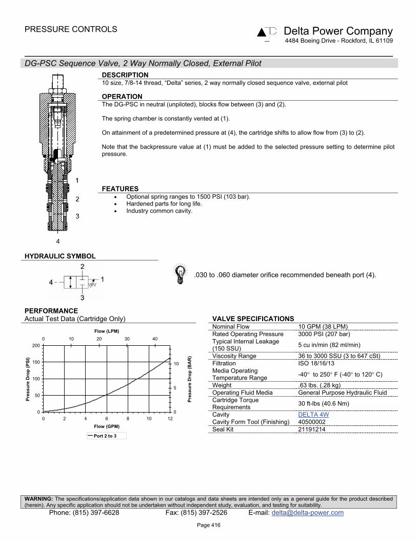
PRESSURE CONTROLS Delta Power Company 4484 Boeing Drive - Rockford, IL 61109
WARNING: The specifications/application data shown in our catalogs and data sheets are intended only as a general guide for the product described (herein). Any specific application should not be undertaken without independent study, evaluation, and testing for suitability.
Phone: (815) 397-6628 Fax: (815) 397-2526 E-mail: [email protected]
DG-PSC Sequence Valve, 2 Way Normally Closed, External Pilot
DESCRIPTION 10 size, 7/8-14 thread, “Delta” series, 2 way normally closed sequence valve, external pilot OPERATION The DG-PSC in neutral (unpiloted), blocks flow between (3) and (2). The spring chamber is constantly vented at (1). On attainment of a predetermined pressure at (4), the cartridge shifts to allow flow from (3) to (2). Note that the backpressure value at (1) must be added to the selected pressure setting to determine pilot pressure. FEATURES
• Optional spring ranges to 1500 PSI (103 bar). • Hardened parts for long life. • Industry common cavity.
HYDRAULIC SYMBOL
.030 to .060 diameter orifice recommended beneath port (4).
PERFORMANCE Actual Test Data (Cartridge Only) VALVE SPECIFICATIONS
Nominal Flow 10 GPM (38 LPM) Rated Operating Pressure 3000 PSI (207 bar) Typical Internal Leakage (150 SSU) 5 cu in/min (82 ml/min)
Viscosity Range 36 to 3000 SSU (3 to 647 cSt) Filtration ISO 18/16/13 Media Operating Temperature Range -40° to 250° F (-40° to 120° C)
Weight .63 lbs. (.28 kg) Operating Fluid Media General Purpose Hydraulic Fluid Cartridge Torque Requirements 30 ft-lbs (40.6 Nm)
Cavity DELTA 4W Cavity Form Tool (Finishing) 40500002 Seal Kit 21191214
0
50
100
150
200
0 2 4 6 8 10 12
Flow (GPM)
Pres
sure
Dro
p (P
SI)
0
5
10
0 10 20 30 40Flow (LPM)
Pres
sure
Dro
p (B
AR
)
Port 2 to 3
Page 416

PRESSURE CONTROLS Delta Power Company 4484 Boeing Drive - Rockford, IL 61109
WARNING: The specifications/application data shown in our catalogs and data sheets are intended only as a general guide for the product described (herein). Any specific application should not be undertaken without independent study, evaluation, and testing for suitability.
Phone: (815) 397-6628 Fax: (815) 397-2526 E-mail: [email protected]
DIMENSIONS
ORDERING INFORMATION DG-PSC - - -
OPTIONS BODIES
Buna Standard 00 Blank Without Body Viton Standard V0 N 1/4 NPTF Ports
Buna, Knob 0K S #6 SAE Ports Viton Knob VK
Buna, Internal Adjust 0I Viton, Internal Adjust VI PRESSURE RANGE Buna, Tamper Proof 0T 0425 50-425 PSI Viton, Tamper Proof VT 1500 425-1500 PSI
TAMPER PROOF Fill in 4 Digit Pressure Setting Example: 0500-500PSI
Page 417

PRESSURE CONTROLS Delta Power Company
4484 Boeing Drive - Rockford, IL 61109
WARNING: The specifications/application data shown in our catalogs and data sheets are intended only as a general guide for the product described (herein). Any specific application should not be undertaken without independent study, evaluation, and testing for suitability.
Phone: (815) 397-6628 Fax: (815) 397-2526 E-mail: [email protected]
DG-PSI Sequence Valve, 3 Way Normally Open, Internal Pilot
DESCRIPTION 10 size, 7/8-14 thread, “Delta” series, 3 way normally open internal pilot sequence valve OPERATION The DG-PSI in neutral (un-piloted), allows flow between (3) and (2) bi-directional, while blocking at (4). The spring chamber is constantly vented at (1). On attainment of a predetermined pressure at (4), the cartridge shifts to close (3) to (2), while opening (4) to (3). Note that the backpressure value at (1) must be added to the selected pressure setting to determine pilot pressure necessary to open valve. FEATURES
• Optional spring ranges to 1500 PSI (103 bar). • Hardened parts for long life. • Industry common cavity.
HYDRAULIC SYMBOL
PERFORMANCE Actual Test Data (Cartridge Only) VALVE SPECIFICATIONS
Nominal Flow 10 GPM (38 LTR/M) Rated Operating Pressure 3000 PSI (207 bar) Typical Internal Leakage (150 SSU) 5 cu in/min (82 ml/min)
Viscosity Range 36 to 3000 SSU (3 to 647 cSt) Filtration ISO 18/16/13 Media Operating Temperature Range -40° to 250° F (-40° to 120° C)
Weight .63 lbs. (.28 kg) Operating Fluid Media General Purpose Hydraulic Fluid Cartridge Torque Requirements 30 ft-lbs (40.6 Nm)
Cavity DELTA 4W Cavity Form Tool (Finishing) 40500002 Seal Kit 21191214
0
500
1000
1500
2000
0 2 4 6 8 10 12
Flow (GPM)
Pre
ssu
re D
rop
(P
SI)
0
50
100
0 5 10 15 20 25 30 35 40 45
Flow (LPM)
Pre
ssu
re D
rop
(B
AR
)
Port 4 to 3 Port 2 to 3
Page 418

PRESSURE CONTROLS Delta Power Company
4484 Boeing Drive - Rockford, IL 61109
WARNING: The specifications/application data shown in our catalogs and data sheets are intended only as a general guide for the product described (herein). Any specific application should not be undertaken without independent study, evaluation, and testing for suitability.
Phone: (815) 397-6628 Fax: (815) 397-2526 E-mail: [email protected]
DIMENSIONS
ORDERING INFORMATION DG-PSI - - -
OPTIONS BODIES
Buna Standard 00 Blank Without Body Viton Standard V0 N 1/4 NPTF Ports
Buna, Knob 0K S #6 SAE Ports Viton, Knob VK
Buna, Internal Adjust 0I Viton, Internal Adjust VI PRESSURE RANGE Buna, Tamper Proof 0T 0425 50-425 PSI Viton, Tamper Proof VT 1500 425-1500 PSI
TAMPER PROOF Fill in 4 Digit Pressure Setting Example: 0500-500PSI
Page 419

PRESSURE CONTROLS Delta Power Company 4484 Boeing Drive - Rockford, IL 61109
WARNING: The specifications/application data shown in our catalogs and data sheets are intended only as a general guide for the product described (herein). Any specific application should not be undertaken without independent study, evaluation, and testing for suitability.
Phone: (815) 397-6628 Fax: (815) 397-2526 E-mail: [email protected]
DG-PSO Sequence Valve, 2 Way Normally Open, External Pilot
DESCRIPTION 10 size, 7/8-14 thread, “Delta” series, 2 way normally open sequence valve, external pilot OPERATION The DG-PSO in neutral (un-piloted), allows flow between (3) and (2) bi-directionally. The spring chamber is constantly vented at (1). On attainment of a predetermined pressure at (4), the cartridge shifts to block flow from (3) to (2). Note that the backpressure value at (1) must be added to the selected pressure setting to determine pilot pressure necessary to close valve. FEATURES
• Optional spring ranges to 1500 PSI (103 bar). • Hardened parts for long life. • Industry common cavity.
HYDRAULIC SYMBOL
Orifice .030 - .060 Dia. recommended beneath port (4).
PERFORMANCE Actual Test Data (Cartridge Only) VALVE SPECIFICATIONS
Nominal Flow 10 GPM (38 LTR/M) Rated Operating Pressure 3000 PSI (207 bar) Typical Internal Leakage (150 SSU) 5 cu in/min (82 ml/min)
Viscosity Range 36 to 3000 SSU (3 to 647 cSt) Filtration ISO 18/16/13 Media Operating Temperature Range -40° to 250° F (-40° to 120° C)
Weight .62 lbs. (.28 kg) Operating Fluid Media General Purpose Hydraulic Fluid Cartridge Torque Requirements 30 ft-lbs (40.6 Nm)
Cavity DELTA 4W Cavity Form Tool (Finishing) 40500002 Seal Kit 21191214
0
25
50
75
100
125
150
0 2 4 6 8 10 12
Flow (GPM)
Pres
sure
Dro
p (P
SI)
0
5
10
0 10 20 30 40
Flow (LPM)
Pres
sure
Dro
p (B
AR
)
Port 2 to 3
Page 420

PRESSURE CONTROLS Delta Power Company 4484 Boeing Drive - Rockford, IL 61109
WARNING: The specifications/application data shown in our catalogs and data sheets are intended only as a general guide for the product described (herein). Any specific application should not be undertaken without independent study, evaluation, and testing for suitability.
Phone: (815) 397-6628 Fax: (815) 397-2526 E-mail: [email protected]
DIMENSIONS
ORDERING INFORMATION DG-PSO - - -
OPTIONS BODIES
Buna Standard 00 Blank Without Body Viton Standard V0 N 1/4 NPTF Ports
Buna, Knob 0K S #6 SAE Ports Viton Knob VK
Buna, Internal Adjust 0I Viton, Internal Adjust VI PRESSURE RANGE Buna, Tamper Proof 0T 0425 50-425 PSI Viton, Tamper Proof VT 1500 425-1500 PSI
TAMPER PROOF Fill in 4 Digit Pressure Setting Example: 0500-500PSI
Page 421

PRESSURE CONTROLS Delta Power Company 4484 Boeing Drive - Rockford, IL 61109
WARNING: The specifications/application data shown in our catalogs and data sheets are intended only as a general guide for the product described (herein). Any specific application should not be undertaken without independent study, evaluation, and testing for suitability.
Phone: (815) 397-6628 Fax: (815) 397-2526 E-mail: [email protected]
DG-PSS Hot Oil Shuttle Valve
DESCRIPTION 10 size, 7/8-14 thread, “Delta” series, hot oil shuttle valve OPERATION The DG-PSS, with internal piloting at port (1) or (3), oil will flow from the port opposite of the port piloted to port (2), thus removing oil from the low-pressure side for cooling or filtration purposes. The Valve is spring bias neutral, relying solely on the internal pilot pressure signal to shift to either side. The DG-PSS is closed in transition. FEATURES
• Hardened parts for long life. • Industry common cavity.
HYDRAULIC SYMBOL
PERFORMANCE Actual Test Data (Cartridge Only) VALVE SPECIFICATIONS
Nominal Flow 12 GPM (45 LTR/M) Rated Operating Pressure 3000 PSI (207 bar) Typical Internal Leakage (150 SSU) 5 cu/in per/min (82 ml/min)
Viscosity Range 36 to 3000 SSU (3 to 647 cSt) Filtration ISO 18/16/13 Media Operating Temperature Range -40° to 250° F (-40° to 120° C)
Weight .34 lbs. (.15 kg) Operating Fluid Media General Purpose Hydraulic Fluid Cartridge Torque Requirements 30 ft-lbs (40.6 Nm)
Cavity DELTA 4W Cavity Form Tool (Finishing) 40500002 Seal Kit 21191212
0
50
100
150
200
0 2 4 6 8 10 12
Flow (GPM)
Pres
sure
Dro
p (P
SI)
0
5
10
0 10 20 30 40Flow (LPM)
Pres
sure
Dro
p (B
AR
)
Port 3 to 2 Port 1 to 2
Page 422

PRESSURE CONTROLS Delta Power Company 4484 Boeing Drive - Rockford, IL 61109
WARNING: The specifications/application data shown in our catalogs and data sheets are intended only as a general guide for the product described (herein). Any specific application should not be undertaken without independent study, evaluation, and testing for suitability.
Phone: (815) 397-6628 Fax: (815) 397-2526 E-mail: [email protected]
DIMENSIONS
ORDERING INFORMATION DG-PSS - - -
OPTIONS BODIES
Buna Standard 00 Blank Without Body Viton Standard V0 N 1/4 NPTF Ports
S #6 SAE Ports CRACK PRESSURE
0040 40 PSI 0080 80 PSI 0120 120 PSI 0160 160 PSI 0000 0 PSI (NO SPRING)
BODY WEIGHT: .99 Lbs./ .45 Kg
Page 423

PRESSURE CONTROLS Delta Power Company
4484 Boeing Drive - Rockford, IL 61109
WARNING: The specifications/application data shown in our catalogs and data sheets are intended only as a general guide for the product described (herein). Any specific application should not be undertaken without independent study, evaluation, and testing for suitability.
Phone: (815) 397-6628 Fax: (815) 397-2526 E-mail: [email protected]
DG-PTC Sequence Valve, Normally Open, External Pilot
DESCRIPTION 10 size, 7/8-14 thread, “Delta” series, external pilot, normally open. OPERATION The DG-PTC allows flow at ports (3) and (2). On attainment of a predetermined pressure at port (4), the valve shifts to block flow from port (3) to (2). Spring Chamber is constantly vented to port (1). FEATURES
• Hardened parts for long life. • Industry common cavity.
HYDRAULIC SYMBOL
.030 to .060 diameter orifice recommended beneath port (4).
PERFORMANCE Actual Test Data (Cartridge Only) VALVE SPECIFICATIONS
Nominal Flow 10 GPM (38 LTR/M) Rated Operating Pressure 3000 PSI (207 bar) Typical Internal Leakage (150 SSU) 5 cu in/min (82 ml/min)
Viscosity Range 36 to 3000 SSU (3 to 647 cSt) Filtration ISO 18/16/13 Media Operating Temperature Range -40° to 250° F (-40° to 120° C)
Weight .39 lbs. (.18 kg) Operating Fluid Media General Purpose Hydraulic Fluid Cartridge Torque Requirements 30 ft-lbs (40.6 Nm)
Cavity DELTA 4W Cavity Form Tool (Finishing) 40500002 Seal Kit 21191108
0
50
100
150
200
250
300
350
0 2 4 6 8 10 12 14
Flow (gpm)
Pre
ssur
e D
rop
(psi
)
0
5
10
15
20
0 10 20 30 40 50
Flow (lpm)
Pre
ssur
e D
rop
(bar
)
Page 424

PRESSURE CONTROLS Delta Power Company
4484 Boeing Drive - Rockford, IL 61109
WARNING: The specifications/application data shown in our catalogs and data sheets are intended only as a general guide for the product described (herein). Any specific application should not be undertaken without independent study, evaluation, and testing for suitability.
Phone: (815) 397-6628 Fax: (815) 397-2526 E-mail: [email protected]
DIMENSIONS
ORDERING INFORMATION DG-PTC - - -
OPTIONS BODIES
Buna Standard 00 Blank Without Body Viton Standard V0 N 1/4” NPTF PORT
S #6 SAE Ports SPRING BIAS 0050 50 PSI 0180 180 PSI ±10%
Page 425

PRESSURE CONTROLS Delta Power Company
4484 Boeing Drive - Rockford, IL 61109
WARNING: The specifications/application data shown in our catalogs and data sheets are intended only as a general guide for the product described (herein). Any specific application should not be undertaken without independent study, evaluation, and testing for suitability.
Phone: (815) 397-6628 Fax: (815) 397-2526 E-mail: [email protected]
DG-PTO Sequence Valve, Normally Closed, External Pilot
DESCRIPTION 10 size, 7/8-14 thread, “Delta” series, external pilot, normally closed. OPERATION The DG-PTO blocks flow at ports (3) and (2). On attainment of a predetermined pressure at port (4), the valve shifts to allow flow from port (3) to (2). Spring Chamber is constantly vented to port (1). FEATURES
• Hardened parts for long life. • Industry common cavity.
HYDRAULIC SYMBOL
.030 to .060 diameter orifice recommended beneath port (4).
PERFORMANCE Actual Test Data (Cartridge Only) VALVE SPECIFICATIONS
Nominal Flow 10 GPM (38 LTR/M) Rated Operating Pressure 3000 PSI (207 bar) Typical Internal Leakage (150 SSU) 5 cu in/min (82 ml/min)
Viscosity Range 36 to 3000 SSU (3 to 647 cSt) Filtration ISO 18/16/13 Media Operating Temperature Range -40° to 250° F (-40° to 120° C)
Weight .39 lbs. (.18 kg) Operating Fluid Media General Purpose Hydraulic Fluid Cartridge Torque Requirements 30 ft-lbs (40.6 Nm)
Cavity DELTA 4W Cavity Form Tool (Finishing) 40500002 Seal Kit 21191108
0
50
100
150
200
250
300
350
0 2 4 6 8 10 12 14
Flow (gpm)
Pre
ssur
e D
rop
(psi
)
0
5
10
15
20
0 10 20 30 40 50
Flow (lpm)
Pre
ssur
e D
rop
(bar
)
Page 426

PRESSURE CONTROLS Delta Power Company
4484 Boeing Drive - Rockford, IL 61109
WARNING: The specifications/application data shown in our catalogs and data sheets are intended only as a general guide for the product described (herein). Any specific application should not be undertaken without independent study, evaluation, and testing for suitability.
Phone: (815) 397-6628 Fax: (815) 397-2526 E-mail: [email protected]
DIMENSIONS
ORDERING INFORMATION DG-PTO - - -
OPTIONS BODIES
Buna Standard 00 Blank Without Body Viton Standard V0 N 1/4” NPTF PORT
S #6 SAE Ports SPRING BIAS 0050 50 PSI 0180 180 PSI ±10%
Page 427

PRESSURE CONTROLS Delta Power Company 4484 Boeing Drive - Rockford, IL 61109
WARNING: The specifications/application data shown in our catalogs and data sheets are intended only as a general guide for the product described (herein). Any specific application should not be undertaken without independent study, evaluation, and testing for suitability.
Phone: (815) 397-6628 Fax: (815) 397-2526 E-mail: [email protected]
DF-PWE Sequence Valve, Normally Closed, External Pilot
DESCRIPTION 10 size, 7/8-14 thread, “Delta” series, external pilot normally closed, sequence valve. OPERATION The DF-PWI blocks flow at ports (2) and (1). On attainment of a predetermined pressure at (3) the valve shifts to a allow flow from (1) to (2). FEATURES
• Hardened parts for long life. • Optional spring ranges to 1500 PSI (103 bar). • Industry common Cavity.
HYDRAULIC SYMBOL
.030 to .060 diameter orifice recommended beneath port (3).
PERFORMANCE Actual Test Data (Cartridge Only) VALVE SPECIFICATIONS
Nominal Flow 10 GPM (38 LPM) Rated Operating Pressure 3000 PSI (207 bar) Typical Internal Leakage (150 SSU) 5 cu in/min (82 ml/min)
Viscosity Range 36 to 3000 SSU (3 to 647 cSt) Filtration ISO 18/16/13 Media Operating Temperature Range -40° to 250° F (-40° to 120° C)
Weight .57 lbs. (.26 kg) Operating Fluid Media General Purpose Hydraulic Fluid Cartridge Torque Requirements 30 ft-lbs (40.6 Nm)
Cavity DELTA 3W Cavity Form Tool (Finishing) 40500001
Seal Kit 21191206
0
50
100
150
200
0 2 4 6 8 10 12 14Flow (GPM)
Pre
ssur
e D
rop
(PS
I)
0
5
10
0 5 10 15 20 25 30 35 40 45 50Flow (LPM)
Pre
ssur
e D
rop
(BA
R)
Port 1 to 2
Page 428
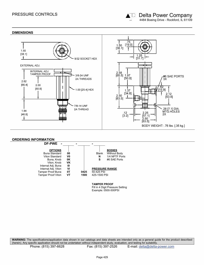
PRESSURE CONTROLS Delta Power Company 4484 Boeing Drive - Rockford, IL 61109
WARNING: The specifications/application data shown in our catalogs and data sheets are intended only as a general guide for the product described (herein). Any specific application should not be undertaken without independent study, evaluation, and testing for suitability.
Phone: (815) 397-6628 Fax: (815) 397-2526 E-mail: [email protected]
DIMENSIONS
ORDERING INFORMATION DF-PWE - - -
OPTIONS BODIES
Buna Standard 00 Blank Without Body Viton Standard V0 N 1/4 NPTF Ports
Buna, Knob 0K S #6 SAE Ports Viton, Knob VK
Internal Adj. Buna 0I Internal Adj. Viton VI PRESSURE RANGE
Tamper Proof Buna 0T 0425 50-425 PSI Tamper Proof Viton VT 1500 425-1500 PSI
TAMPER PROOF Fill in 4 Digit Pressure Setting Example: 0500-500PSI
Page 429
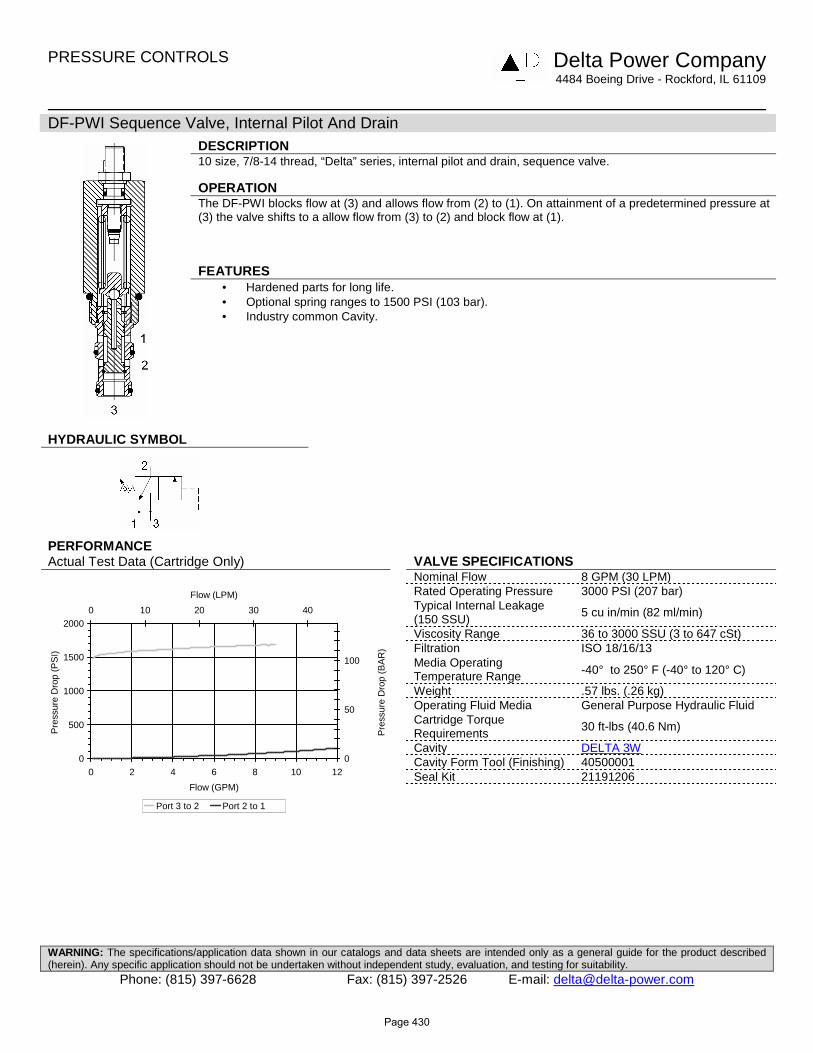
PRESSURE CONTROLS Delta Power Company
4484 Boeing Drive - Rockford, IL 61109
WARNING: The specifications/application data shown in our catalogs and data sheets are intended only as a general guide for the product described (herein). Any specific application should not be undertaken without independent study, evaluation, and testing for suitability.
Phone: (815) 397-6628 Fax: (815) 397-2526 E-mail: [email protected]
DF-PWI Sequence Valve, Internal Pilot And Drain
DESCRIPTION 10 size, 7/8-14 thread, “Delta” series, internal pilot and drain, sequence valve. OPERATION The DF-PWI blocks flow at (3) and allows flow from (2) to (1). On attainment of a predetermined pressure at (3) the valve shifts to a allow flow from (3) to (2) and block flow at (1). FEATURES
• Hardened parts for long life. • Optional spring ranges to 1500 PSI (103 bar). • Industry common Cavity.
HYDRAULIC SYMBOL
PERFORMANCE Actual Test Data (Cartridge Only) VALVE SPECIFICATIONS
Nominal Flow 8 GPM (30 LPM) Rated Operating Pressure 3000 PSI (207 bar) Typical Internal Leakage (150 SSU)
5 cu in/min (82 ml/min)
Viscosity Range 36 to 3000 SSU (3 to 647 cSt) Filtration ISO 18/16/13 Media Operating Temperature Range -40° to 250° F (-40° to 120° C)
Weight .57 lbs. (.26 kg) Operating Fluid Media General Purpose Hydraulic Fluid Cartridge Torque Requirements
30 ft-lbs (40.6 Nm)
Cavity DELTA 3W Cavity Form Tool (Finishing) 40500001
Seal Kit 21191206
0
500
1000
1500
2000
0 2 4 6 8 10 12
Flow (GPM)
Pre
ssur
e D
rop
(PS
I)
0
50
100
0 10 20 30 40
Flow (LPM)
Pre
ssur
e D
rop
(BA
R)
Port 3 to 2 Port 2 to 1
Page 430

PRESSURE CONTROLS Delta Power Company
4484 Boeing Drive - Rockford, IL 61109
WARNING: The specifications/application data shown in our catalogs and data sheets are intended only as a general guide for the product described (herein). Any specific application should not be undertaken without independent study, evaluation, and testing for suitability.
Phone: (815) 397-6628 Fax: (815) 397-2526 E-mail: [email protected]
DIMENSIONS
ORDERING INFORMATION DF-PWI - - -
OPTIONS BODIES
Buna Standard 00 Blank Without Body Viton Standard V0 N 1/4 NPTF Ports
Buna, Knob 0K S #6 SAE Ports Viton Knob VK
Internal Adj. Buna 0I Internal Adj. Viton VI PRESSURE RANGE
Tamper Proof Buna 0T 0425 50-425 PSI Tamper Proof Viton VT 1500 425-1500 PSI
TAMPER PROOF Fill in 4 Digit Pressure Setting Example: 0500-500PSI
Page 431

PRESSURE CONTROLS Delta Power Company
4484 Boeing Drive - Rockford, IL 61109
WARNING: The specifications/application data shown in our catalogs and data sheets are intended only as a general guide for the product described (herein). Any specific application should not be undertaken without independent study, evaluation, and testing for suitability.
Phone: (815) 397-6628 Fax: (815) 397-2526 E-mail: [email protected]
SL-PWA Sequence Valve, Normally Closed, Internal Pilot
DESCRIPTION 16 size, 1 5/16-12 thread, “Super” series, internal pilot normally closed, sequence valve OPERATION The SL-PWA blocks flow from ports (3) to (2). On attainment of a predetermined pressure at (3) the valve shifts to allow flow from (3) to (2). Port (1) should be a tank line. FEATURES
• Hardened parts for long life. • Industry common cavity.
HYDRAULIC SYMBOL
PERFORMANCE Actual Test Data (Cartridge Only) VALVE SPECIFICATIONS
Nominal Flow 40 GPM (151 LPM) Rated Operating Pressure 3500 PSI (241 bar) Viscosity Range 36 to 3000 SSU (3 to 647 cSt) Filtration ISO 18/16/13 Media Operating Temperature Range -40° to 250° F (-40° to 120° C)
Weight 1.15 Lbs. (.52 kg) Operating Fluid Media General Purpose Hydraulic Fluid Cartridge Torque Requirements 90 ft-lbs (122 Nm)
Cavity SUPER 3WS Cavity Form Tool (Finishing) 40500021
Seal Kit 21191404
0
500
1000
1500
2000
0 5 10 15 20 25Flow (GPM)
Pre
ssu
re D
rop
(P
SI)
0153045607590105120135
0 15 30 45 60 75 90
Flow (LPM)
Pressu
re Dro
p (B
AR
)
Page 432
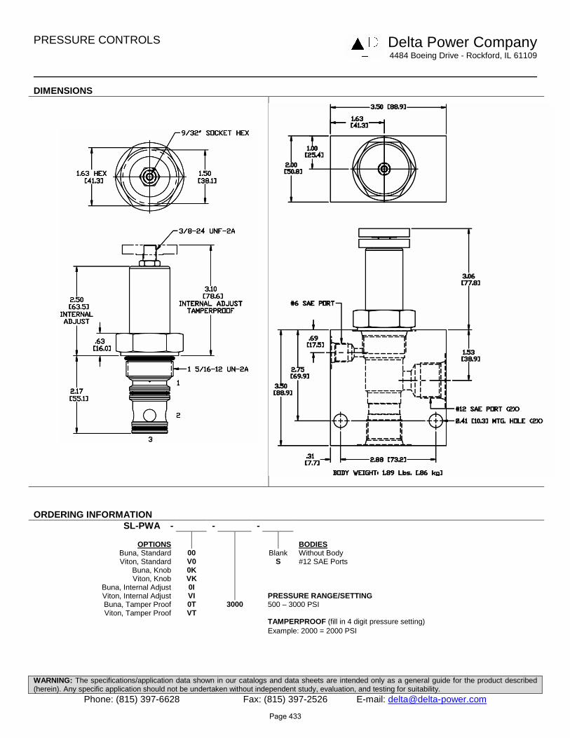
PRESSURE CONTROLS Delta Power Company
4484 Boeing Drive - Rockford, IL 61109
WARNING: The specifications/application data shown in our catalogs and data sheets are intended only as a general guide for the product described (herein). Any specific application should not be undertaken without independent study, evaluation, and testing for suitability.
Phone: (815) 397-6628 Fax: (815) 397-2526 E-mail: [email protected]
DIMENSIONS
ORDERING INFORMATION SL-PWA - - -
OPTIONS BODIES
Buna, Standard 00 Blank Without Body Viton, Standard V0 S #12 SAE Ports
Buna, Knob 0K Viton, Knob VK
Buna, Internal Adjust 0I Viton, Internal Adjust VI PRESSURE RANGE/SETTING Buna, Tamper Proof 0T 3000 500 – 3000 PSI Viton, Tamper Proof VT
TAMPERPROOF (fill in 4 digit pressure setting) Example: 2000 = 2000 PSI
Page 433

PRESSURE CONTROLS Delta Power Company
4484 Boeing Drive - Rockford, IL 61109
WARNING: The specifications/application data shown in our catalogs and data sheets are intended only as a general guide for the product described (herein). Any specific application should not be undertaken without independent study, evaluation, and testing for suitability.
Phone: (815) 397-6628 Fax: (815) 397-2526 E-mail: [email protected]
SL-PWB Sequence Valve, Normally Closed, Internal Pilot with Reverse Free Flow
DESCRIPTION 16 size, 1 5/16-12 thread, “Super” series, internal pilot normally closed, sequence valve w/ reverse free flow OPERATION The SL-PWB blocks flow from ports (3) to (2). On attainment of a predetermined pressure at (3) the valve shifts to allow flow from (3) to (2). Port (1) should be a tank line. Reverse flow from (2) to (3) occurs when the pressure at port (2) is at least 45 PSI (3.1 bar) higher than at port (3). FEATURES
• Hardened parts for long life. • Industry common cavity.
HYDRAULIC SYMBOL
PERFORMANCE Actual Test Data (Cartridge Only) VALVE SPECIFICATIONS
Nominal Flow 40 GPM (151 LPM) Rated Operating Pressure 3500 PSI (241 bar) Viscosity Range 36 to 3000 SSU (3 to 647 cSt) Filtration ISO 18/16/13 Media Operating Temperature Range -40° to 250° F (-40° to 120° C)
Weight 1.15 Lbs. (.52 kg) Operating Fluid Media General Purpose Hydraulic Fluid Cartridge Torque Requirements 90 ft-lbs (122 Nm)
Cavity SUPER 3WS Cavity Form Tool (Finishing) 40500021
Seal Kit 21191404
0
500
1000
1500
2000
2500
0 10 20 30 40
Flow (GPM)
Pre
ssu
re (
PS
I)
0
50
100
150
0 25 50 75 100 125 150
Flow (LPM)
Pre
ssu
re (
BA
R)
Page 434

PRESSURE CONTROLS Delta Power Company
4484 Boeing Drive - Rockford, IL 61109
WARNING: The specifications/application data shown in our catalogs and data sheets are intended only as a general guide for the product described (herein). Any specific application should not be undertaken without independent study, evaluation, and testing for suitability.
Phone: (815) 397-6628 Fax: (815) 397-2526 E-mail: [email protected]
DIMENSIONS
ORDERING INFORMATION SL-PWB - - -
OPTIONS BODIES
Buna, Standard 00 Blank Without Body Viton, Standard V0 S #12 SAE Ports
Buna, Knob 0K Viton, Knob VK
Buna, Internal Adjust 0I Viton, Internal Adjust VI PRESSURE RANGE/SETTING Buna, Tamper Proof 0T 3000 500 – 3000 PSI Viton, Tamper Proof VT
TAMPERPROOF (fill in 4 digit pressure setting) Example: 2000 = 2000 PSI
Page 435

Page 436
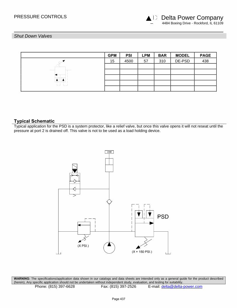
PRESSURE CONTROLS Delta Power Company 4484 Boeing Drive - Rockford, IL 61109
WARNING: The specifications/application data shown in our catalogs and data sheets are intended only as a general guide for the product described (herein). Any specific application should not be undertaken without independent study, evaluation, and testing for suitability.
Phone: (815) 397-6628 Fax: (815) 397-2526 E-mail: [email protected]
Shut Down Valves
GPM PSI LPM BAR MODEL PAGE 15 4500 57 310 DE-PSD 438
Typical Schematic Typical application for the PSD is a system protector, like a relief valve, but once this valve opens it will not reseat until the pressure at port 2 is drained off. This valve is not to be used as a load holding device.
Page 437
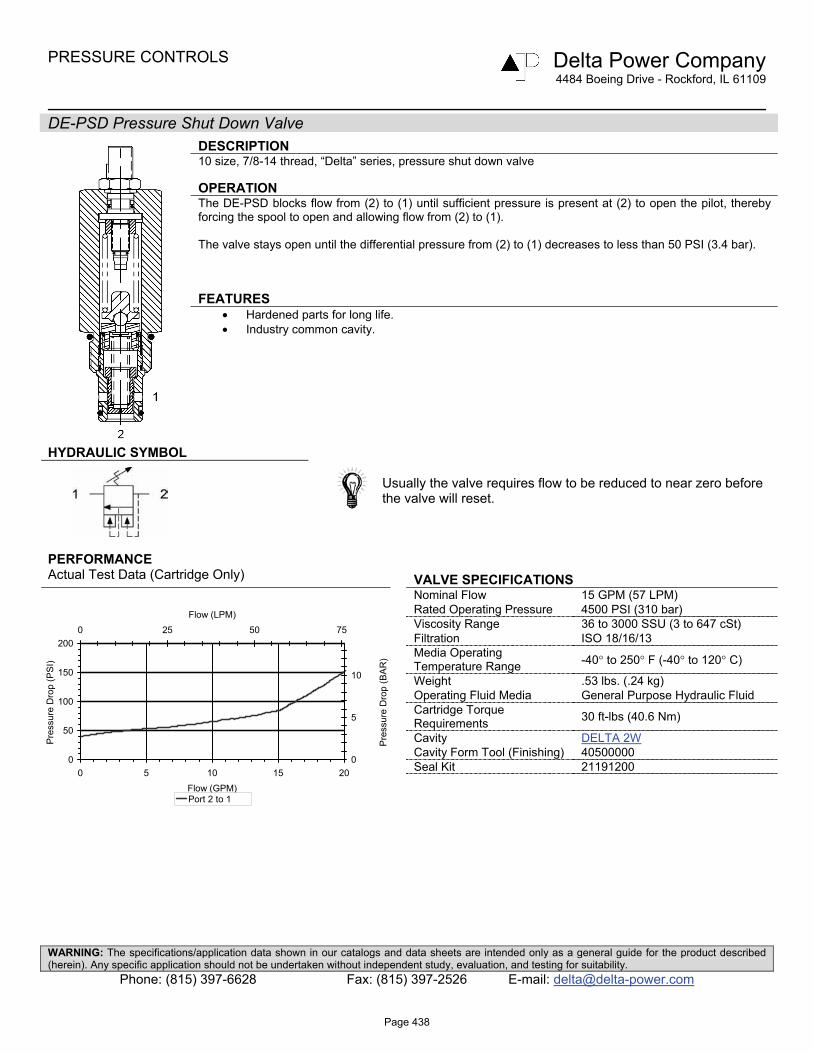
PRESSURE CONTROLS Delta Power Company 4484 Boeing Drive - Rockford, IL 61109
WARNING: The specifications/application data shown in our catalogs and data sheets are intended only as a general guide for the product described (herein). Any specific application should not be undertaken without independent study, evaluation, and testing for suitability.
Phone: (815) 397-6628 Fax: (815) 397-2526 E-mail: [email protected]
DE-PSD Pressure Shut Down Valve
DESCRIPTION 10 size, 7/8-14 thread, “Delta” series, pressure shut down valve OPERATION The DE-PSD blocks flow from (2) to (1) until sufficient pressure is present at (2) to open the pilot, thereby forcing the spool to open and allowing flow from (2) to (1). The valve stays open until the differential pressure from (2) to (1) decreases to less than 50 PSI (3.4 bar). FEATURES
• Hardened parts for long life. • Industry common cavity.
HYDRAULIC SYMBOL
Usually the valve requires flow to be reduced to near zero before the valve will reset.
PERFORMANCE Actual Test Data (Cartridge Only) VALVE SPECIFICATIONS
Nominal Flow 15 GPM (57 LPM) Rated Operating Pressure 4500 PSI (310 bar) Viscosity Range 36 to 3000 SSU (3 to 647 cSt) Filtration ISO 18/16/13 Media Operating Temperature Range -40° to 250° F (-40° to 120° C)
Weight .53 lbs. (.24 kg) Operating Fluid Media General Purpose Hydraulic Fluid Cartridge Torque Requirements 30 ft-lbs (40.6 Nm)
Cavity DELTA 2W Cavity Form Tool (Finishing) 40500000
Seal Kit 21191200
0
50
100
150
200
0 5 10 15 20Flow (GPM)
Pre
ssur
e D
rop
(PS
I)
0
5
10
0 25 50 75Flow (LPM)
Pre
ssur
e D
rop
(BA
R)
Port 2 to 1
Page 438

PRESSURE CONTROLS Delta Power Company 4484 Boeing Drive - Rockford, IL 61109
WARNING: The specifications/application data shown in our catalogs and data sheets are intended only as a general guide for the product described (herein). Any specific application should not be undertaken without independent study, evaluation, and testing for suitability.
Phone: (815) 397-6628 Fax: (815) 397-2526 E-mail: [email protected]
DIMENSIONS
ORDERING INFORMATION DE-PSD - - -
OPTIONS BODIES
Buna Standard 00 Blank Without Body Viton Standard V0 N 3/8 NPTF Ports Note: aluminum, NOT durability rated for
Buna, Knob 0K S #8 SAE Ports 4000 PSI. Consult factory for body options. Viton, Knob VK
Internally Adj. Buna 0I PRESSURE RANGE/SETTING Internally Adj. Viton VI 3000 100 – 3000 PSI Tamper Proof Buna 0T 4500 3000 – 4500 PSI Tamper Proof Viton VT
TAMPER PROOF Fill in 4 Digit Pressure Setting Example: 0500-500 PSI
Page 439

Page 440

PRESSURE CONTROLS Delta Power Company 4484 Boeing Drive - Rockford, IL 61109
WARNING: The specifications/application data shown in our catalogs and data sheets are intended only as a general guide for the product described (herein). Any specific application should not be undertaken without independent study, evaluation, and testing for suitability.
Phone: (815) 397-6628 Fax: (815) 397-2526 E-mail: [email protected]
Unloading Valves
GPM PSI LPM BAR MODEL PAGE 1 4000 4 276 DF-PUV 442
Typical Schematic Typical application for the PUV is for pump unloading in an accumulator system. When the PUV setting is reached, the PUV opens, venting the PCR valves pilot signal. This unloads the pump until accumulator system pressure drops to 80% of the PUV setting. The PUV closes which blocks the PCR pilot signal to recharge the accumulator and the cycle is repeated. NOTE: Max. PUV flow 1 GPM.
Page 441

PRESSURE CONTROLS Delta Power Company 4484 Boeing Drive - Rockford, IL 61109
WARNING: The specifications/application data shown in our catalogs and data sheets are intended only as a general guide for the product described (herein). Any specific application should not be undertaken without independent study, evaluation, and testing for suitability.
Phone: (815) 397-6628 Fax: (815) 397-2526 E-mail: [email protected]
DF-PUV Pilot Operated Unloading Valve
DESCRIPTION 10 size, 7/8-14 thread, “Delta” series, pilot operated unloading valve OPERATION The DF-PUV blocks all ports until pressure at port (2) exceeds pressure setting, or pressure at port (3) is above 80 % of pressure setting. FEATURES
• Hardened parts for long life. • Industry common cavity.
HYDRAULIC SYMBOL
Typical circuits require an orifice to be placed at ports (2) and (3).
PERFORMANCE Actual Test Data (Cartridge Only) VALVE SPECIFICATIONS
Nominal Flow 1 GPM (3.8 LPM) Rated Operating Pressure 4000 PSI (276 bar) Loading Pressure as % of Unloading Pressure
80% (Ex. If the PUV cracks at 3000 PSI, it will reseat at 2400 PSI)
Viscosity Range 36 to 3000 SSU (3 to 647 cSt) Filtration ISO 18/16/13 Media Operating Temperature Range -40° to 250° F (-40° to 120° C)
Weight .60 lbs. (.27 kg) Operating Fluid Media General Purpose Hydraulic Fluid Cartridge Torque Requirements 30 ft-lbs (40.6 Nm)
Cavity DELTA 3W Cavity Form Tool (Finishing) 40500001 (min. pre-drill .563 dia.)
Seal Kit 21191206
0
5
10
15
20
0 0.25 0.5 0.75 1Flow (GPM)
Pre
ssur
e D
rop
(PS
I)
0
0.25
0.5
0.75
1
1.25
0 0.05 0.1 0.15 0.2 0.25Flow (LPM)
Pre
ssur
e D
rop
(BA
R)
Port 2 to 1 (full pilot pressue applied @ port 3)
2 1
3
Page 442

PRESSURE CONTROLS Delta Power Company 4484 Boeing Drive - Rockford, IL 61109
WARNING: The specifications/application data shown in our catalogs and data sheets are intended only as a general guide for the product described (herein). Any specific application should not be undertaken without independent study, evaluation, and testing for suitability.
Phone: (815) 397-6628 Fax: (815) 397-2526 E-mail: [email protected]
DIMENSIONS
ORDERING INFORMATION DF-PUV - - -
OPTIONS BODIES
Buna Standard 00 Blank Without Body Viton Standard V0 N 1/4 NPTF Ports
Buna, Knob 0K S #6 SAE Ports Viton, Knob VK
Internally Adj. Buna 0I PRESSURE RANGE/SETTING Internally Adj. Viton VI Ext./Int. Adjustable Tamper Proof Buna 0T 3000 300 – 3000 PSI Tamper Proof Viton VT
Tamper Proof Fill in 4 Digit Pressure Setting Example: 0500 – 500 PSI
Page 443

Page 444