o3-hub application guide - delta controls
TRANSCRIPT

O3-HUBApplication Guide Edition 1.9

Copyright
Copyright © Delta Controls Inc. All rights reserved.
No part of this document may be reproduced, transmitted, transcribed, storedin a retrieval system, or translated into any language (natural or computer),in any form or by any means, without the prior written permission of DeltaControls Inc.
Limited permission is granted to reproduce documents released in Adobe®
Portable Document Format (PDF) electronic format in paper format.Documents released in PDF electronic format may be printed by end-users fortheir own use using a printer such as an inkjet or laser device. Authorizeddistributors of Delta Controls Inc. products (Delta Partners) may print PDFdocuments for their own internal use or for use by their customers.Authorized Delta Partners may engage a printing or copying company toproduce copies of released PDF documents with the prior written permissionof Delta Controls Inc.
Information in this document is subject to change without notice and does notrepresent a commitment to past versions of this document on the part ofDelta Controls Inc. Delta Controls Inc. may make improvements and/orchanges to this document /the associated software/or associated hardwareat any time.
BACspec, BACstat, the Delta logo, ORCAview, ORCAweb, Earthright,enteliWEB, enteliBUS, enteliMESH, enteliTOUCH, enteliZONE, enteliSTAT, andVirtual Stat are registered trademarks of Delta Controls Inc.
EnOcean®, EnOcean Alliance logo, EnOcean Alliance member logo andEnOcean Alliance technology logo (=ingredient logo) are registeredtrademarks of EnOcean GmbH and EnOcean Alliance Inc. All other product orservice names are the property of their respective owners.
© EnOcean Alliance Inc., 2017.
All other trademarks are the property of their respective owners.
Document edition: 1.9

Table of Contents
Introduction 1
About the O3 System and Sensor Hub 1
Setting Up the Sensor Hub 3
Main Steps to Set Up the Sensor Hub After Installation 3
Creating an Object Database 4
Object Instance Numbers for Sensor Hub Input Sensors 4
Object Instance Numbers for Sensor Hub Speaker, Bluetooth, andEnOcean 7
Object Instance Numbers for Sensor Hub Light Ring Display 9
Object Instance Numbers for IR Blaster 13
Object Instance Number for Sensor Hub Termination Switch 15
Object Instance Numbers for Universal I/O (2xP models) 15
Calibrating the Sensor Hub Temperature 16
Creating a Custom Light Ring Color 17
Loading Custom Sounds 18
Configuring the Sensor Hub IR Blaster 20
Troubleshooting the Sensor Hub 21
The sensor hub is offline 21
The sensor hub has an error state 21
The sensor hub no longer appears on the IOM object page 21
O3 App 23
Getting Started with the O3 App 27
Before you begin 27
Install an O3-DIN controller 27
Install and set up a sensor hub 27
Create rooms and activities for the O3 app 28
Install and log in to the O3 app 28
O3 Room Concept 29

What is an O3 Room? 29
Components of an O3 Room 29
What is an O3 Room Activity? 29
What is an Occupant? 29
Permissions 30
Room and O3 App 30
Creating O3 Rooms 31
Managing O3 Rooms 35
O3 Room Configuration Reference 37
Configuration 37
O3 Sensor Hubs 37
Room Controls 37
Activities 43
Principal Occupant 43
O3 Room Activity Concept 44
What is an O3 Room Activity? 44
Activities and the O3 App 44
Creating O3 Room Activities 45
Managing O3 Room Activities 47
O3 Room Activity Configuration Reference 49
Configuration 49
Activity Controls 49
Deploying the O3 App for Building Occupants 52
Users with a Google Account 52
Users with an enteliWEB Account 52
Document Revision History 54

O3-HUB Application GuideEdition 1.9
Page 1 of 54
Introduction
This guide describes how to set up and control the O3-HUB sensor hub using DeltaControls' O3 integrated room controller.
It applies to the following sensor hub models:
l O3-HUB l O3-HUB-2xPl O3-HUB-En868 l O3-HUB-En868-2xPl O3-HUB-En902 l O3-HUB-En902-2xP
About the O3 System and Sensor Hub
The O3 is a flexible, modular room control system that integrates HVAC, dimmablelighting, door access, and motorized blind control in a single controller.
As part of the O3 system, the O3 sensor hub combines multiple temperaturesensors, humidity sensors, occupancy detection, and wireless integration in a singledevice, providing occupant- and location-based control for the modern office ormeeting space.
Connected to an O3-DIN controller, the hub's sensor input values are mapped toBACnet objects on the controller, which can then be programmed in GCL+.
2xP models come with two universal points that you can configure as inputs oroutputs in enteliWEB.
Hubs equipped with EnOcean radios can receive wireless EnOcean data from up to32 EnOcean devices.
All sensor hubs come with an IR blaster for A/V remote control, as well as aBluetooth beacon that enables users to control room comfort settings from theirphones using the O3 mobile app.

Introduction
Page 2 of 54 O3-HUB Application GuideEdition 1.9
The following diagram depicts a typical O3 system:

O3-HUB Application GuideEdition 1.9
Page 3 of 54
Setting Up the Sensor Hub
Main Steps to Set Up the Sensor Hub After Installation
This section describes how to set up the sensor hub.
During an installation, it's assumed a unique address between 2 and 9 isassigned to the sensor hub using the sensor hub's rotary switch. The sensorhub cannot be software addressed.
1. Enable CANbus protocol on the O3-DIN controller's NET3 port.
When you connect the O3-HUB to the NET3 port of the controller, make surethe NP3 object on the controller is set to support CANbus protocol type. Youalso need to select Activate in the Command field in the same object.
After a connection has been successfully established between the sensor huband the O3-DIN controller, the IOM object displays an online status for thesensor hub.
2. You can create the object database manually in enteliWEB for the sensor hub,or you can auto-create the object database from an existing template usingthe Database Creation tool (enteliWEB 4.12 and higher).
The database includes BACnet objects that map to the sensor input values onthe sensor hub. Similar objects are also used to control the LED light ring andspeaker. These objects follow a specific instance numbering format. A full listof BACnet objects for the sensor hub can be found at the Object InstanceNumbers on the Sensor Hub topic.
3. Create GCL+ programs in enteliWEB for room control.
These programs use the BACnet objects that you've created to execute controlsequences.
4. (Optional) Configure the sensor hub to receive EnOcean data from EnOceandevices. This step only applies to the O3-HUB-Enxxx models.
See the O3 EnOcean application guide.
5. (Optional) Configure room settings for the O3 mobile app.
If you are employing the O3 mobile app on the same site, see Getting Startedwith the O3 App and Deploying the O3 App for Building Occupants for moreinformation.

Setting Up the Sensor Hub
Page 4 of 54 O3-HUB Application GuideEdition 1.9
Creating an Object Database
BACnet objects are used to map the O3-HUB input sensor values and configure lightring features. These are created in enteliWEB on the O3-DIN controller that controlsthe sensor hub.
You can create objects for the sensor hub manually or you can auto-create themfrom an existing template using the Database Creation tool.
The following tables list all the objects for the sensor hub.
Note: The letter "s" in the object instance numbers represents the sensor hub'saddress switch setting (2–9).
Object Instance Numbers for Sensor Hub Input Sensors
Object NameInstanceNumber
Description
Room Temperature AI30s000 Calculated room temperature at 1 m(3 ft) above the floor. This is acomposite value taken from thehub's internal temperature sensors(AI30s010 and AI30s012) and theinfrared temperature sensor(AI30s011). Range −40°C to 125°C(–40°F to 257°F).
For optimal accuracy, thetemperature can be calibrated to aspecific reference point in the room.See Calibrating the Sensor HubTemperature for more details.
Estimate OccupantHumidity
AI30s001 Calculated humidity (0–100%) at 1m (3 ft) above the floor.
Occupancy BI30s002 Active state = room occupied. Setthe Binary Device Configurationproperty to Occupied/Unoccupied.See Occupancy States below formore details about how occupancyis determined.
Motion Sensor BI30s003 Active state = motion detected. Setthe Binary Device Configurationproperty to Motion/None.

O3-HUB Application GuideEdition 1.9
Page 5 of 54
Object NameInstanceNumber
Description
Light Level AI30s004 Intensity of light being measured(0–65535 lux).
Color Temperature AI30s005 Color temperature of light beingmeasured (0–65535 K).
Red Light Intensity AI30s006 Red component of light beingmeasured. No units but scaled from0–65535.
Green Light Intensity AI30s007 Green component of light beingmeasured. No units but scaled from0–65535.
Blue Light Intensity AI30s008 Blue component of light beingmeasured. No units but scaled from0–65535.
Humidity at Ceiling AI30s009 Humidity at ceiling height (0–100%), read from the hub'shumidity sensor.
Internal Temperature AI30s010 Temperature at ceiling height, readfrom the hub's humidity sensor.Range −40°C to 125°C (−40°F to257°F).
IR Temperature AI30s011 Average temperature of all roomsurfaces in the sensor's field of view,read from the hub's IR sensor.Range −40°C to 125°C (−40°F to257°F).
Internal Temperature 2 AI30s012 Temperature at ceiling height, readfrom the hub's digital temperaturesensor.Range −40°C to 125°C (−40°F to257°F).
Sound Pressure Level AI30s016 Unfiltered audio levels (0–120 dB)across the entire spectrum reportedin dB SPL scale. Read-only.

Setting Up the Sensor Hub
Page 6 of 54 O3-HUB Application GuideEdition 1.9
Object NameInstanceNumber
Description
Motion Sensitivity AV30s033 PIR motion sensor sensitivity,expressed as a percentage (0–100%). 100% = maximumsensitivity, 0% = minimumsensitivity. Default value is 80%.May need adjusting based on roomsize and layout.
Occupancy AudioSensitivity
AV30s036 Sensitivity of the audio portion ofthe occupancy algorithm, expressedas a percentage (0–100%). 100% =maximum sensitivity, 0% =minimum sensitivity. Default valueis 80%.
Occupancy InactivityPeriod
AV30s038 The amount of time (in seconds) ittakes the hub to return to theunoccupied state when no motionand no audio activity is detected.Default value is 300 seconds (5minutes).
Occupancy AudioRetrigger Period
AV30s039 The amount of time (in seconds)that activity sounds can cause thehub to remain in the occupied stateafter motion is detected. Defaultvalue is 1200 seconds (20 minutes).Measured frommost recent motiondetection event.
Occupancy States
A state change from unoccupied to occupied is triggered when motion is detected inthe room, or by a combination of motion and sound. Sound alone does not trigger astate change.
The occupancy state is extended when either motion or sound is detected in theroom. This sound level has to be above the baseline audio level that the sensor hubhas previously established. In addition, new sounds that fall outside of theOccupancy Audio Retrigger Period (set by the value of AV30s039) are not allowed toextend the occupancy state. This feature (available with firmware 4.6 andlater) reduces artificial extension of the occupancy state by background noise.

O3-HUB Application GuideEdition 1.9
Page 7 of 54
If no motion or sound is detected after a set amount of time (the OccupancyInactivity Period), the sensor hub reports the room as unoccupied. This sound levelhas to be below the baseline audio level that the sensor hub has previouslyestablished. You can change the Occupancy Inactivity Period using objectAV30s038.
Object Instance Numbers for Sensor Hub Speaker, Bluetooth, and EnOcean
Object NameInstanceNumber
Description
Speaker Volume AV30s005 Sets the speaker volume in therange 0–10. Default value is 0 (Off).
Play Sound MV30s006 Plays sounds defined by theassociated MIC. Set to 1 (Idle/Off)for no sound. Values 2 to X arepredefined sounds. Reverts to Idleafter a sound is played. See LoadingCustom Sounds to the Sensor Hub.
Sound List MIC MICx Contains predefined stock sounds.Available through the DatabaseCreation tool or via download fromthe sensor hub product page onGeorge Support (O3-HUBScaleObjects.zip).
Sound Repeat AV30s008 Sets how many times a soundshould by played. 0 indicatesindefinite repeats until changed.
Bluetooth TransmitPower
MV30s024 Sets the strength (maximumtransmit power) of the Bluetoothbeacon. Default value is 4 dBM.

Setting Up the Sensor Hub
Page 8 of 54 O3-HUB Application GuideEdition 1.9
Object NameInstanceNumber
Description
Bluetooth TransmitPower MIC
MICx Contains the maximum transmitpower states used by the MV30s024object. There are 8 allowable states.
l −40 dBm
l −20 dBm
l −16 dBm
l −12 dBm
l −8 dBm
l −4 dBm
l 0 dBm
l 4 dBm
Available through the DatabaseCreation tool or via download fromthe sensor hub product page onGeorge Support (O3-HUBScaleObjects.zip).
Enable BLE BV30s026 When set to On, the Bluetooth LowEnergy (BLE) beacon is enabled andbroadcasting.
Enable EnOcean BV30s030 When set to On, EnOceancommunication is enabled on sensorhub models equipped with EnOceanantennae. Goes into fault if not anEnOcean hub. Default value is Off.
Bluetooth Beacon MACAddress
CSV30s040 Displays the MAC address of thesensor hub's Bluetooth beacon.
This object needs to be created sothat the O3 app is aware of the roomin which the sensor hub is installed.

O3-HUB Application GuideEdition 1.9
Page 9 of 54
Object NameInstanceNumber
Description
EnOcean ID CSV30s044 Displays the EnOcean base ID ofonboard chip. The EnOcean sendingID is determined by adding the baseID to the number of the sendingdevice. For example, if a hub'sEnOcean ID is ff9db180 and you aresending from EnOcean device 4, thesending ID would be ff9db184. If theEnOcean device being used were 12,the sending ID would be ff9db18c,since the value is in hexadecimal.
Object Instance Numbers for Sensor Hub Light Ring Display
These objects control the LED light ring's brightness and behaviors or patterns.
Object NameInstanceNumbers
Description
Light Ring Red AV30s000 Sets the red component of RGBvalue of light ring (0–255).See Creating a Custom Light RingColor on the Sensor Hub for moredetails.
Light Ring Green AV30s001 Sets the green component of RGBvalue of light ring (0–255).See Creating a Custom Light RingColor on the Sensor Hub for moredetails.
Light Ring Blue AV30s002 Sets the blue component of RGBvalue of light ring (0–255).See Creating a Custom Light RingColor on the Sensor Hub for moredetails.
Light Ring Brightness AV30s004 Sets the overall brightness of thelight ring (0–100%).
Setting Up the Sensor Hub
Page 10 of 54 O3-HUB Application GuideEdition 1.9
Object NameInstanceNumbers
Description
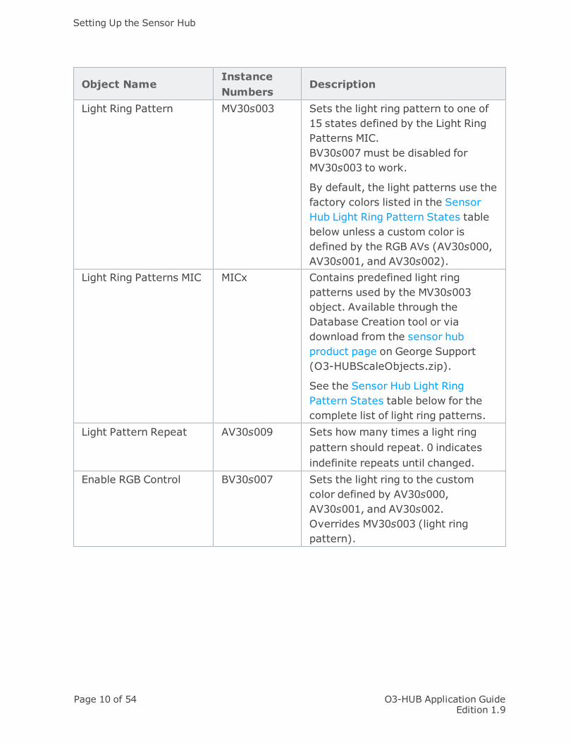
Light Ring Pattern MV30s003 Sets the light ring pattern to one of15 states defined by the Light RingPatterns MIC.BV30s007 must be disabled forMV30s003 to work.
By default, the light patterns use thefactory colors listed in the SensorHub Light Ring Pattern States tablebelow unless a custom color isdefined by the RGB AVs (AV30s000,AV30s001, and AV30s002).
Light Ring Patterns MIC MICx Contains predefined light ringpatterns used by the MV30s003object. Available through theDatabase Creation tool or viadownload from the sensor hubproduct page on George Support(O3-HUBScaleObjects.zip).
See the Sensor Hub Light RingPattern States table below for thecomplete list of light ring patterns.
Light Pattern Repeat AV30s009 Sets how many times a light ringpattern should repeat. 0 indicatesindefinite repeats until changed.
Enable RGB Control BV30s007 Sets the light ring to the customcolor defined by AV30s000,AV30s001, and AV30s002.Overrides MV30s003 (light ringpattern).

O3-HUB Application GuideEdition 1.9
Page 11 of 54
Object NameInstanceNumbers
Description
Enable Status Mode BV30s029 When set to True/On, the light ringdisplays the hardware status of themajor components of the sensorhub. The light ring is divided intofour quadrants, with each quadrantdisplaying the status of a specificcomponent. Green indicates normalfunctioning, yellow indicates acomponent is disabled, and redindicates a failure or error.
For example, when the sensor hub ispowered on for the first time, it isnormal to see green for allquadrants except the EnOceanquadrant. The EnOcean quadrantappears yellow because EnOcean isdisabled by default. See the sensorhub installation guide for moredetails.
Sensor Hub Light Ring Pattern States
This table lists the states defined by the Light Ring Patterns MIC object. Thesestates are supplied to the MV30s003 object that issues a command to display aspecific light ring pattern. The MIC object is part of the O3-HUBScaleObjects.zip fileavailable on the sensor hub product page on George Support.

Setting Up the Sensor Hub
Page 12 of 54 O3-HUB Application GuideEdition 1.9
StatePatternName
DescriptionSuggestedUse
FactoryColors
1 Idle/Off No ring pattern is displayed. None2 Swirl Single spot of light spins
around the ring once beforethe ring flashes twice. Endswith a prolonged flash thatlasts for 2 seconds.
Blue
3 Fast Swirl A faster version of the Swirlsequence.
Blue
4 Power On Spins a single spot of lightaround the ring 3 times.
When thesensor hubpowers on.
Green
5 OccupancyTriggered
Spins a single spot of lightaround the ring 3 times.
Whenoccupancyis detectedin theroom.
White
6 RequestReceived
The ring flashes 3 times in asequence that lasts for 2seconds.
To confirmreceipt of aroomcommand.
Green
7 HeatingActive
The entire ring fades in andout.
When theroom isheating.
Red
8 CoolingActive
The entire ring fades in andout.
When theroom iscooling.
Blue
9 Request NotUnderstood
The ring flashes 4 timesfollowed by a prolonged lightflash that lasts for 2seconds.
Yellow
10 ErrorCondition
The entire ring flashes 8times.
Red
11 AlarmCondition
Flashes alternate betweenboth halves of the ring, for atotal of 16 flashes.
Red

O3-HUB Application GuideEdition 1.9
Page 13 of 54
StatePatternName
DescriptionSuggestedUse
FactoryColors
12 Christmas The entire ring flashes andalternates between 2 colors.This sequence is repeated 8times.
Red andGreen
13 Awake The entire ring lights up andstays lit while a spot of moreintense light in the samecolor travels around the ringtwice.
Blue
14 Power On(Alternate)
3 spots of light spin aroundonce before the ring flashestwice. The entire ring thenlights up and stays lit for 2seconds.
When thesensor hubpowers on.
Violet,Blue andYellow
15 OccupancyTriggered(Alternate)
3 spots of light spin aroundonce, followed by asequence where a light spottravels down each half ofthe ring to the point wherethe 2 ring halves meetbefore moving back to theirpoint of origin.
Whenoccupancyis detectedin theroom.
VioletandCyan
Object Instance Numbers for IR Blaster
Note: The IR blaster feature is available in firmware 4.6 and higher.
Using the following objects, you can set up the sensor hub's IR blaster to transmitinfrared signals to control room appliances. Remote control codes using Pronto hexformat are saved in CSV objects as string values. See Configuring the Sensor Hub IRBlaster for more details.
Object NameInstanceNumber
Description
Send IR Blaster Code MV30s010 Sends an IR code fromCSV30s011 to CSV30s022. Whenset to Idle/Off (state 1), no codeis sent. Reverts to Idle/Off aftera code is sent.

Setting Up the Sensor Hub
Page 14 of 54 O3-HUB Application GuideEdition 1.9
Object NameInstanceNumber
Description
IR Transmitter MIC MICx Contains Pronto IR codes for theIR blaster. Available through theDatabase Creation tool or viadownload from the sensor hubproduct page on George Support(O3-HUBScaleObjects.zip).
IR Repeat AV30s023 Sets how many times an IR codeshould be sent per transmission.By default, a code is sent onceper transmission.
IR Code 1 CSV30s011 Data in this object is sent outthrough the IR blaster whenMV30s010 is set to state 2.
IR Code 2 CSV30s012 Data in this object is sent outthrough the IR blaster whenMV30s010 is set to state 3.
IR Code 3 CSV30s013 Data in this object is sent outthrough the IR blaster whenMV30s010 is set to state 4.
IR Code 4 CSV30s014 Data in this object is sent outthrough the IR blaster whenMV30s010 is set to state 5.
IR Code 5 CSV30s015 Data in this object is sent outthrough the IR blaster whenMV30s010 is set to state 6.
IR Code 6 CSV30s016 Data in this object is sent outthrough the IR blaster whenMV30s010 is set to state 7.
IR Code 7 CSV30s017 Data in this object is sent outthrough the IR blaster whenMV30s010 is set to state 8.
IR Code 8 CSV30s018 Data in this object is sent outthrough the IR blaster whenMV30s010 is set to state 9.

O3-HUB Application GuideEdition 1.9
Page 15 of 54
Object NameInstanceNumber
Description
IR Code 9 CSV30s019 Data in this object is sent outthrough the IR blaster whenMV30s010 is set to state 10.
IR Code 10 CSV30s020 Data in this object is sent outthrough the IR blaster whenMV30s010 is set to state 11.
IR Code 11 CSV30s021 Data in this object is sent outthrough the IR blaster whenMV30s010 is set to state 12.
IR Code 12 CSV30s022 Data in this object is sent outthrough the IR blaster whenMV30s010 is set to state 13.
When programming the sensor hub to transmit multiple infrared signals atthe same time, allow a one second interval between signals to allow eachsignal to complete its transmission.
Object Instance Number for Sensor Hub Termination Switch
The sensor hub includes built-in network termination through a manual switchsetting. The switch is factory set to no termination (OFF). To enable termination,move the switch from OFF to TERM.
Object NameInstanceNumber
Description
CAN TerminationStatus
BV30s043 Read-only value that indicates whethertermination is on or off on the sensor hub.
Object Instance Numbers for Universal I/O (2xP models)
Object Name Instance Number Description2xP universalI/O 1
AI/BI/MI/AO/BO/MO30s098
Used to configure an O3-HUB-2xPUniversal I/O 1.
2xP universalI/O 2
AI/BI/MI/AO/BO/MO30s099
Used to configure an O3-HUB-2xPUniversal I/O 2.

Setting Up the Sensor Hub
Page 16 of 54 O3-HUB Application GuideEdition 1.9
Calibrating the Sensor Hub Temperature
The sensor hub temperature reading needs to be calibrated to match a referenceroom temperature. After calibration, the accuracy of the hub's temperature sensoris ± 0.5 degrees when measured within a band ± 5 degrees from the calibratedtemperature.
To calibrate the temperature:
l In enteliWEB, enter a correction factor in the AI30s000 object's Calibrationproperty (where "s" represents the hub's address switch setting). Thecorrection factor is the difference between the reference temperature and theAI30s000 object's present temperature value. For example, if the referencetemperature is 21°C and the AI30s000 temperature value is 22°C, thecorrection factor that should be recorded is −1°C.

O3-HUB Application GuideEdition 1.9
Page 17 of 54
Creating a Custom Light Ring Color
The light ring color represented by the RGB triplet does not exactly matchthe same RGB color displayed on computer monitors. When setting acustom light ring color, use the sensor hub to preview the color.
To create a new light ring color and display it on the sensor hub:
1. Create the following AV objects to set the red, green and blue values of thecustom color ("s" represents the hub's address switch setting).
ObjectName
InstanceNumber
Description
Red value AV30s000 Sets the red value for the light ring RGB, 0(Off) to 255 (max).
Greenvalue
AV30s001 Sets the green value for the light ring, 0 (Off)to 255 (max).
Bluevalue
AV30s002 Sets the blue value for the light ring, 0 (Off)to 255 (max).
2. To display the new custom color, create object BV30s007. Set this object valueto True or On. The light ring displays the color until you set the object value toFalse or Off.
In firmware 4.6 and later, you can also apply custom colors to light ringpatterns.
Examples of light ring colors and their associated RGB triplets: green (0,255,0),white (84,84,84), blue (0,0,255), red (255,0,0).
Light Ring Display Command Prioritization
All commands interrupt other commands in progress, and are processed inthe following priority: Sensor hub status display (highest priority) >Brightness AV > Custom RGB color BV > Light ring patterns (lowestpriority). For example, if a command to play a ring pattern and a statusrequest were sent together, both commands would be accepted withouterror but only the status is displayed on the light ring.

Setting Up the Sensor Hub
Page 18 of 54 O3-HUB Application GuideEdition 1.9
Loading Custom Sounds
O3 firmware version 4.8 and later supports loading custom audio files to the sensorhub. The audio files are represented in BACnet as FIL objects.
To load custom sounds to the sensor hub:
1. Create up to 12 audio files with the following specifications:
l File format: WAV
l Bit resolution: 16 bit
l Sampling rate: 16 kHz
l Audio channel: Mono
The total size of the audio files must not exceed 1.8 Mb. So, for example, youcould create 12 short sounds (approximately 5 seconds each), a single longsound (approximately 1 minute), or some combination of short and medium-length sounds.
2. In enteliWEB, on the O3-DIN controller that controls the sensor hub, create anFIL object for each audio file that you have created.
l To load the files to a specific sensor hub, create FIL objects in the range30s101 to 30s112 (where "s" represents the hub's address switchsetting).
l To load the files to all the connected sensor hubs, create FIL objects inthe range 310101 to 310112.
If there are FIL objects created in the global range (310101–310112)and also FIL objects created in the range of a specific hub (30s101–30s112), the O3 driver will transmit the global files to all hubs exceptthe hub with its own specific files. Global files cannot overwrite hub-specific files. If the files for a specific hub are invalid, the audio loadingfor that hub will end in error; it will not attempt to use any global files.
3. Open each FIL object and upload the audio file that you want to associate withthat FIL.
a. In the Configuration section, click Upload File.
b. In the Load File to Object dialog, click Browse, navigate to the locationof the file, select it, click Open, and then click OK.
c. Click Save to save your changes.

O3-HUB Application GuideEdition 1.9
Page 19 of 54
If you would like to load custom sounds but you also want to keepusing some of the stock sounds, reload the stock sounds you wantusing the same method as the custom sounds. The stock sound filescan be downloaded from the sensor hub product page on GeorgeSupport. Every time new audio is loaded, the audio files are rewritten.Therefore, every time you do an audio load you must provide every fileto be loaded, even if it already exists in memory.
4. If you are loading less than 12 sounds, modify the default Sound List MIC tomatch the number of sounds that you have loaded or, alternatively, create anew MIC.
If you are modifying the default MIC, rename the sounds as needed and deleteany states that are not used. For example, if you are loading 6 sounds, the MICshould only have 7 states (state 1 as Idle/Off and states 2 to 7 as sounds).FIL30s101 corresponds to state 2, FIL30s102 corresponds to state 3, and soon.
5. Reset the O3-DIN controller or, alternatively, command BV30s099 to On. If theFIL objects are valid, the audio files are transmitted to the sensor hub andsaved to its data flash. Depending on the size of the transfer, this can take upto 5 minutes. The light ring displays solid blue while the audio is loading.
If one or more of the files are not in the proper format, or if the totalsize of the audio is larger than the 1.8 Mb of space reserved for audio,no transfer will take place. Only if all files are valid and can becontained within the data space of the sensor hub will the O3-DINcontroller update the sensor hub(s).
6. To verify that the audio transfer was successful, create and/or open objectCSV30s099 (read-only).
Once the audio transfer is complete, the files can be played back using MV30s006.
If the MV30s006 object is commanded to a non-existent sound file, allsounds will play consecutively in an infinite loop until the sensor hub ispower cycled. Make sure the audio MIC does not have any unused states.

Setting Up the Sensor Hub
Page 20 of 54 O3-HUB Application GuideEdition 1.9
Configuring the Sensor Hub IR Blaster
Note: The IR blaster feature is available in firmware 4.6 and later.
To set up the sensor hub to transmit infrared remote control signals:
1. Obtain the remote control codes specific to your appliance brand and model inPronto hex format. Remote control codes are available online on websites suchas www.remotecentral.com/cgi-bin/codes.
2. Create the CSV object or objects with specific instances as listed in the ObjectInstance Numbers for IR Blaster table. You can create up to 12 CSV objects persensor hub.
3. In the CSV object, copy and paste the remote control code into the DefaultValue property field. Make sure your text editor tool does not introduce anyextra characters or spaces in the code.
4. Create an MIC object to store the states associated with specific CSV objectsin the exact order shown in the Object Instance Numbers for IR Blaster table.
5. Create object MV30s010 (where "s" represents the hub's address switchsetting). To transmit a remote control signal, command the MV object value tothe correct state.

O3-HUB Application GuideEdition 1.9
Page 21 of 54
Troubleshooting the Sensor Hub
The IOM object page displays the working status of the sensor hubs on the O3BUSnetwork. In general, the status reflects the health of the connection between thesensor hub and the O3-DIN controller. This topic describes three possible statusesand how to interpret them.
If the sensor hub is still powered, the light ring displays the hardware status until theissue is resolved.
The sensor hub is offline
This could be due to one of the following reasons:
l Faulty network or power wiring between the O3-DIN controller and the sensorhub.
l The NP object on the O3-DIN controller is set to a protocol type other thanCANbus.
l The sensor hub has been assigned the same address as a O3-DIN-PWRINJmodule on the O3BUS network. Both the sensor hub and power injectormodule remain offline until the duplicate addressing is resolved.
l You are using the switched PWR OUT 1 port on the O3-DIN-CPU controller topower the sensor hub and the BO1 object set to OFF. Manually commandBO1 to ON to turn on power to the hub.
The sensor hub has an error state
This could be due to the NET3 port being disabled. Verify that the Out of Service boxon the NP3 object is not checked.
The sensor hub no longer appears on the IOM object page
This could be due to one of the following reasons:
l The sensor hub was offline before the O3-DIN controller was reset. When thecontroller comes back online after a reset, the sensor hub no longer appearson the IOM object page.
l The sensor hub shares the same address as another sensor hub on the O3BUSnetwork. Give all the sensor hubs on the network unique addresses.

Troubleshooting the Sensor Hub
Page 22 of 54 O3-HUB Application GuideEdition 1.9
l You are using the switched PWR OUT 1 port on the O3-DIN-CPU controller topower the sensor hub and the BO1 object set to OFF. Manually commandBO1 to ON to turn on power to the hub.

O3-HUB Application GuideEdition 1.9
Page 23 of 54
O3 App
The O3 app is a room control application for mobile devices. The app communicateswith the O3-DIN room controller and enteliWEB to execute a preset comfort settingin a room. These comfort settings are previously configured by the enteliWEBadministrator to match what the occupants intend to do in the room, for example, ameeting or presentation.
The O3 app relies on the Bluetooth beacon in the sensor hub (O3-HUB) for roomlocation information, and therefore is designed to work only with rooms or spacesthat have O3-HUB devices. enteliWEB determines the room permission level of eachO3 app user on the site.

O3 App
Page 24 of 54 O3-HUB Application GuideEdition 1.9
The O3 app displays a list of rooms closest to the O3 app user. In general, the roomwith the strongest Bluetooth beacon signal appears at the top of this list.
For more information about O3 rooms, see O3 Room Concept.

O3-HUB Application GuideEdition 1.9
Page 25 of 54
Each room or space is associated with one or more activities, each with their ownpreset comfort values. The O3 app user selects an activity option on the app toapply the new comfort values.
(1) Displays the current activity in use. Also displays the current values from thesensors in the room.
(2) Other Activities: List the activities available for selection.
(3) Control: Select Control to change the preset comfort values.
(4) Use the menu icon to go back to the room list.
For more information about O3 room activities, see O3 Room Activity Concept.

O3 App
Page 26 of 54 O3-HUB Application GuideEdition 1.9
The O3 app user can change the preset comfort values using the Control section ofthe app.
The control tiles display the comfort values of the selected activity. Each control isrepresented by an image that changes color and form to reflect its current comfortvalue.
To change these comfort values, touch to open the control tile and tap or drag toadjust the setting.

O3-HUB Application GuideEdition 1.9
Page 27 of 54
Getting Started with the O3 App
Before you begin
l You must have enteliWEB version 4.8 or later installed, with the Web Servicesand Interface API license add-on activated. You can check the status of the
add-on by going to > Configuration> Support.
l A wireless access point must be installed to allow Wi-Fi connections toenteliWEB.
l The enteliWEB server must be set up for HTTPS connections, which requiresinstalling an SSL certificate from a trusted certificate authority (Let's Encryptis a popular free option). The O3 app will not connect to the server if aself-signed certificate is used. To obtain an SSL certificate, the servermust have a DNS-resolvable hostname and access to the internet. Internalserver names and IP addresses are not supported. For more information, seeKBA2037.
Install an O3-DIN controller
Install an O3-DIN-CPU device running firmware version 4.6 or later (or an O3-DIN-SRC device running firmware version 4.7 or later) on a BACnet network. For moreinformation, refer to the O3-DIN-CPU Installation Guide.
Install and set up a sensor hub
1. Install an O3-HUB or O3-HUB-Enxxx sensor hub and connect it to the O3-DINcontroller. Connect the hub's O3BUS port to the controller's NET3 port andconnect the hub's power to the controller's PWR OUT port. For moreinformation, refer to the O3-HUB Installation Guide.
2. To enable the PWR OUT port on the O3-DIN controller, select the controller inenteliWEB, create object BO1, command it to ON, then click Save.
3. In the NP3 object, set Protocol Type to CANbus, set Command to Activate,then click Save.
4. Open the IOM1 object and verify that the sensor hub is online.
5. Create the object database for the sensor hub. You can create objectsmanually in enteliWEB or you can auto-create them from an existing templateusing the Database Creation tool (in enteliWEB 4.12 and higher).
Note: In the following object names, "s" is a placeholder for the hub's rotaryswitch position (2–9).
O3 App
Page 28 of 54 O3-HUB Application GuideEdition 1.9
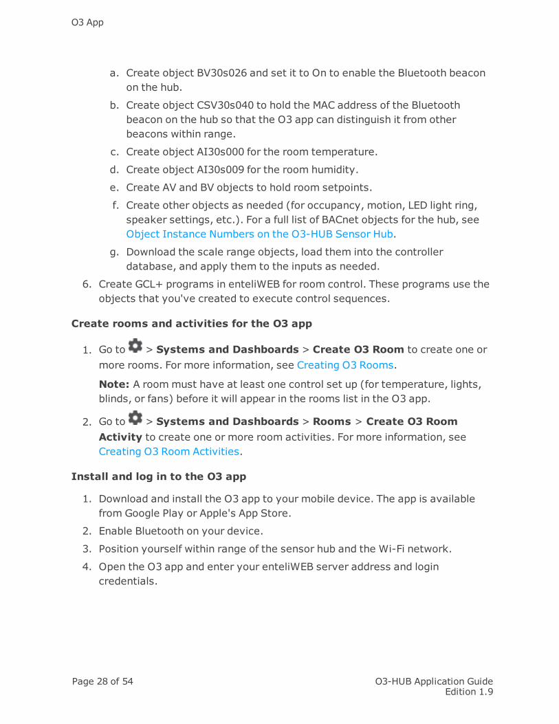
a. Create object BV30s026 and set it to On to enable the Bluetooth beaconon the hub.
b. Create object CSV30s040 to hold the MAC address of the Bluetoothbeacon on the hub so that the O3 app can distinguish it from otherbeacons within range.
c. Create object AI30s000 for the room temperature.
d. Create object AI30s009 for the room humidity.
e. Create AV and BV objects to hold room setpoints.
f. Create other objects as needed (for occupancy, motion, LED light ring,speaker settings, etc.). For a full list of BACnet objects for the hub, seeObject Instance Numbers on the O3-HUB Sensor Hub.
g. Download the scale range objects, load them into the controllerdatabase, and apply them to the inputs as needed.
6. Create GCL+ programs in enteliWEB for room control. These programs use theobjects that you've created to execute control sequences.
Create rooms and activities for the O3 app
1. Go to > Systems and Dashboards > Create O3 Room to create one ormore rooms. For more information, see Creating O3 Rooms.
Note: A roommust have at least one control set up (for temperature, lights,blinds, or fans) before it will appear in the rooms list in the O3 app.
2. Go to > Systems and Dashboards > Rooms > Create O3 RoomActivity to create one or more room activities. For more information, seeCreating O3 Room Activities.
Install and log in to the O3 app
1. Download and install the O3 app to your mobile device. The app is availablefrom Google Play or Apple's App Store.
2. Enable Bluetooth on your device.
3. Position yourself within range of the sensor hub and the Wi-Fi network.
4. Open the O3 app and enter your enteliWEB server address and logincredentials.

O3-HUB Application GuideEdition 1.9
Page 29 of 54
O3 Room Concept
What is an O3 Room?
We define an O3 room as an area of a building where occupant comfort is controlledby a Delta Controls O3-DIN controller and one or more sensor hubs and where theoccupants use the Delta Controls O3 app to manage their comfort.
Components of an O3 Room
Devices
Sensor HubO3-DIN-CPU or O3-
DIN-SRCMobile device with
O3 app
Sensors inroom
Temperaturein sensor hub
Humidityin sensor hub
CO2on room wall
Controls via O3app
Temperature set-point
Lights Blinds Fans
What is an O3 Room Activity?
See What is an O3 Room Activity?
What is an Occupant?
An occupant is a person who is in a room and can use the O3 app.
An occupant with the proper permissions uses the O3 app to choose an activity forthe room. The activity defines the comfort settings for the room.
See Permissions below to understand what a principal occupant is.

O3 App
Page 30 of 54 O3-HUB Application GuideEdition 1.9
Permissions
Each setpoint and other comfort setting for a room is assigned one of the followingpermission levels: principal occupant, everyone in room, no permission.
Principal Occupant
Principal Occupant permission allows the named user(s) to adjust the setpoint orother comfort setting for the room.
When the permissions for all setpoints and comfort settings for a room are set toPrincipal Occupant, then the room is displayed on the O3 app room list for theroom's principal occupant users only.
A principal occupant can be either an enteliWEB user or an O3 app user.
Everyone in Room
Everyone in Room permission allows any enteliWEB user or O3 app user to adjustthe setpoint or other comfort setting for the room. The room is displayed on the O3app room list for all occupants.
No Permission
No Permission does not allow any enteliWEB user or O3 app user to adjust thesetpoint or other comfort setting for the room. When the permission for all roomcomfort settings is set to No Permission, then the room is not displayed on the O3app room list for any occupant.
Room and O3 App
The O3 app displays a room on its room list when all of the following rules are true:
l The app user is a member of the O3 Room Guests group or another group withthe same object, service, and device permissions.
l The room has at least one of the following controls configured: temperature,lights, blinds, or fans.
l The control permissions are set to Everyone in Room or Principal Occupant. Ifthe permission is set to Principal Occupant, the app user must be designatedas a principal occupant or belong to a group that is designated as a principaloccupant.
The O3 Room page does not support the nameFormat feature in config.xml.

O3-HUB Application GuideEdition 1.9
Page 31 of 54
Creating O3 Rooms
An O3 room is an area of a building where occupant comfort is controlled by an O3-DIN controller and one or more sensor hubs and is managed through the O3 app.
O3 rooms are created on the Create O3 Room page ( > Systems andDashboards > Create O3 Room).
To create a room:
1. Enter the Room Name (for example, "Conference Room").
2. Optional: Select a Room Photo to identify the room in the app.
3. Optional: Enter a Description for the room. The description is not visible to theapp user.
4. In the O3 Sensor Hubs area, do the following:
a. Click Add to add a new row.
b. In the Device Reference field, start typing the name of the O3-DINcontroller that controls the sensor hub. Select the controller from the listof results.
c. Ensure that the Hub Address is correct. By default, the value is set to 2,the default address for sensor hubs. To edit the address, double-click inthe Hub Address field to make it active, then select a new address fromthe list.
The hub address is displayed in the IOM object (IOM1) of thecontroller. The hub address is the third digit from the left in thehub's IOM address. For example, 302000 indicates a hub addressof 2, 303000 indicates a hub address of 3, 304000 indicates a hubaddress of 4, and so on.
5. In the Room Controls area, do the following:
a. On the Sensors tab:
i. In the Temperature Reference field, enter the AI object that holdsthe temperature of the room (AI30s000, where s is the hubaddress).
ii. In the CO2 Reference field, enter the object that holds the CO2 levelof the room (this reading is not provided by the sensor hub; aseparate CO2 wall sensor must be installed).
O3 App
Page 32 of 54 O3-HUB Application GuideEdition 1.9
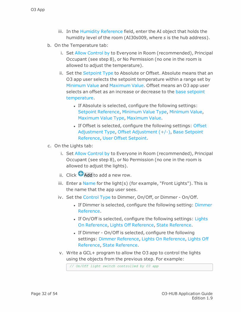
iii. In the Humidity Reference field, enter the AI object that holds thehumidity level of the room (AI30s009, where s is the hub address).
b. On the Temperature tab:
i. Set Allow Control by to Everyone in Room (recommended), PrincipalOccupant (see step 8), or No Permission (no one in the room isallowed to adjust the temperature).
ii. Set the Setpoint Type to Absolute or Offset. Absolute means that anO3 app user selects the setpoint temperature within a range set byMinimum Value and Maximum Value. Offset means an O3 app userselects an offset as an increase or decrease to the base setpointtemperature.
l If Absolute is selected, configure the following settings:Setpoint Reference, Minimum Value Type, Minimum Value,Maximum Value Type, Maximum Value.
l If Offset is selected, configure the following settings: OffsetAdjustment Type, Offset Adjustment (+/-), Base SetpointReference, User Offset Setpoint.
c. On the Lights tab:
i. Set Allow Control by to Everyone in Room (recommended), PrincipalOccupant (see step 8), or No Permission (no one in the room isallowed to adjust the lights).
ii. Click Add to add a new row.
iii. Enter a Name for the light(s) (for example, "Front Lights"). This isthe name that the app user sees.
iv. Set the Control Type to Dimmer, On/Off, or Dimmer - On/Off.
l If Dimmer is selected, configure the following setting: DimmerReference.
l If On/Off is selected, configure the following settings: LightsOn Reference, Lights Off Reference, State Reference.
l If Dimmer - On/Off is selected, configure the followingsettings: Dimmer Reference, Lights On Reference, Lights OffReference, State Reference.
v. Write a GCL+ program to allow the O3 app to control the lightsusing the objects from the previous step. For example:// On/Off light switch controlled by O3 app

O3-HUB Application GuideEdition 1.9
Page 33 of 54
IfOnce ('ON/OFF - ON' = 'On') Then'ON/OFF - StateRef' = 'On''ON/OFF - ON' = 'Off'EndIf
IfOnce ('ON/OFF - OFF' = 'On') Then'ON/OFF - StateRef' = 'Off''ON/OFF - OFF' = 'Off'EndIf
In this example, 'ON/OFF - ON' is the Lights On Reference BVobject, 'ON/OFF - OFF' is the Lights Off Reference BV object, and'ON/OFF - StateRef' is the State Reference BV object.
vi. Optional: Enter an internal Key Name for the light(s) that can beapplied to similar lights in other rooms (for example, "Main Lights"or "Perimeter Lights"). This allows activities to control thesedevices in a consistent way across multiple rooms.
vii. Add additional lights as needed.
d. On the Blinds tab:
i. Set Allow Control by to Everyone in Room (recommended), PrincipalOccupant (see step 8), or No Permission (no one in the room isallowed to adjust the blinds).
ii. Click Add to add a new row.
iii. Enter a Name for the blinds (for example, "West Window"). This isthe name that the app user sees.
iv. In the Position Reference field, enter the AV object that holds thevertical position of the blinds.
v. In the Angle Reference field, enter the AV object that holds theangle of the blinds.
vi. Optional: Enter an internal Key Name for the blinds that can beapplied to similar blinds in other rooms. This allows activities tocontrol these devices in a consistent way across multiple rooms.
vii. Add additional blinds as needed.
e. On the Fans tab:
i. Set Allow Control by to Everyone in Room (recommended), PrincipalOccupant (see step 8), or No Permission (no one in the room isallowed to adjust the fans).
ii. Click Add to add a new row.

O3 App
Page 34 of 54 O3-HUB Application GuideEdition 1.9
iii. Enter a Name for the fans (for example, "Ventilation"). This is thename that the app user sees.
iv. In the Fan Reference field, enter the MV object that holds the fanstate.
v. Optional: Enter an internal Key Name for the fans that can beapplied to similar fans in other rooms. This allows activities tocontrol these devices in a consistent way across multiple rooms.
vi. Add additional fans as needed.
Note: For a room to appear in the rooms list in the O3 app, it must have atleast one of the following controls configured: temperature, lights,blinds, or fans.
6. The Activities area shows any room activities that have been created. Toassociate an activity with the room, select the Enabled check box. To create anew activity, see Creating O3 Room Activities.
7. In the Principal Occupant area, you can designate specific users and/or groupsas the principal room occupant. When room controls permissions are set toPrincipal Occupant, only these users and groups will be able to view andmanage the room comfort settings in the app.
a. To add users to the Principal Occupant list, on the Users tab, click Add,select the users that you want to add, then click OK. To create newusers, see Creating a User help topic.
b. To add groups to the Principal Occupant list, on the Groups tab, clickAdd, select the groups that you want to add, then click OK. To create newgroups, see Creating a Group help topic.
8. Click Create . The room is added to the O3 Rooms list.

O3-HUB Application GuideEdition 1.9
Page 35 of 54
Managing O3 Rooms
An O3 room is an area of a building where occupant comfort is controlled by an O3-DIN controller and one or more sensor hubs and is managed through the O3 app.
O3 rooms are managed on the O3 Rooms page ( > Systems and Dashboards >Rooms), which lists rooms for all sites known to enteliWEB.
Searching the Rooms List
To search the rooms list, start typing a room name in the Search Room field. The listis filtered as you type.
To see everything in the rooms list, clear the Search Room field.
Sorting the Rooms List
To sort the rooms list, click the column heading that you want to sort by.
Opening an Existing Room
To open a room, click its name.
Adding a Room
To add a new room, click Add. The Create O3 Room page opens. For details, seeCreating O3 Rooms.
Copying a Room to a Single Controller
When a room is copied, its configuration—its specific objects andinstances—is replicated in the copy. The object database is not copied. Thecopy process assumes that an identical object database exists in thedestination device.
1. From the rooms list, select the room that you want to copy.
2. Click Copy . The Copy Room dialog opens.
3. Edit the Room Name as needed. Each room name must be unique.
4. Optional: If you want to copy the room to a different controller, double-click inthe Destination Device field to make it active, then start typing the name ofthe destination O3-DIN controller. Select the controller from the list of results.
5. Optional: Edit the Destination Hub Address if needed. If you are copying to thesame device, the hub address must be different. To edit the address, double-

O3 App
Page 36 of 54 O3-HUB Application GuideEdition 1.9
click in the Destination Hub Address field to make it active, then select a newaddress from the list.
6. Click Copy. The room list is updated to include the copied room.
Copying a Room to Multiple Controllers
When a room is copied, its configuration—its specific objects andinstances—is replicated in the copy. The object database is not copied. Thecopy process assumes that an identical object database exists in thedestination device.
1. From the rooms list, select the room that you want to copy.
2. Click Copy to Many . The Copy Room dialog opens.
3. In the Destination area, configure the Site, Device Range, Device Increment,and Hub Address.
4. Click Generate . The Generated Rooms list is updated with the copied rooms.
Deleting a Room
1. From the rooms list, select the room or rooms that you want to delete.
2. Click Delete. A confirmation dialog opens.
3. Click Yes to delete the rooms.

O3-HUB Application GuideEdition 1.9
Page 37 of 54
O3 Room Configuration Reference
Configuration
Room Name
Room Name specifies the name used in enteliWEB and in the O3 app for this room.
Room Photo
Room Photo specifies the image displayed for this room in the O3 app.
Description
Description contains a brief description of the room to help you identify it. Thisdescription is not visible to O3 app users.
O3 Sensor Hubs
Device Reference
Device Reference specifies the O3-DIN controller that is controlling the room.
Hub Address
Hub Address specifies the address of the sensor hub in the room in the range 2through 9. The hub address is set by a rotary dial on the sensor hub. The factorydefault setting is 2. The hub's current address setting can be confirmed by openingthe O3-DIN controller's IOM object (IOM1). The hub address is the third digit fromthe left in the sensor hub's IOM address in the Hardware Devices table. For example,302000 indicates a hub address of 2, 303000 indicates a hub address of 3, 304000indicates a hub address of 4, and so on.
Room Controls
Sensors
Temperature Reference
Temperature Reference specifies the AI object of the sensor hub that holds thecomposite temperature value for the room (AI30s000). For details, see ObjectInstance Numbers for Sensor Hub Input Sensors.
CO2 Reference
CO2 Reference specifies an AI or AV object reference for the CO2 sensor. The sensorhub does not include a CO2 sensor. A wall-mounted CO2 sensor must be used.

O3 App
Page 38 of 54 O3-HUB Application GuideEdition 1.9
Humidity Reference
Humidity Reference specifies the AI object of the sensor hub that holds the relativehumidity value for the room (AI30s009). For details, see Object Instance Numbersfor Sensor Hub Input Sensors.
Temperature
Allow Control by
Allow Control by specifies which O3 app users are allowed to adjust the temperaturesetpoint for the room.
Everyone in Room, Principal Occupant, No Permission
Setpoint Type
Setpoint Type specifies how the O3 app user is allowed to adjust the temperaturesetpoint for the room.
l Absolutemeans that an O3 app user selects the setpoint temperature within arange set by Minimum Value and Maximum Value.
l Offsetmeans an O3 app user selects an offset as an increase or decrease tothe base setpoint temperature.
Setpoint Type affects the Setpoint Value setting for activities that you assign to theroom.
Minimum Value Type
When Setpoint Type is set to Absolute, Minimum Value Type specifies how MinimumValue is specified.
l Absolutemeans that Minimum Value specifies a temperature value.
l Object Referencemeans that Minimum Value specifies an object reference forthe AV object that holds a temperature value.
Maximum Value Type
When Setpoint Type is set to Absolute, Maximum Value Type specifies howMaximum Value is specified.
l Absolutemeans that Maximum Value specifies a temperature value.
l Object Referencemeans that Maximum Value specifies an object reference forthe AV object that holds a temperature value.

O3-HUB Application GuideEdition 1.9
Page 39 of 54
Setpoint Reference
When Setpoint Type is set to Absolute, Setpoint Reference specifies an objectreference for the AV object that holds the desired setpoint that is requested by anO3 app user. The O3 app updates this object when the user adjusts the desiredtemperature.
Minimum Value
When Setpoint Type is set to Absolute, Minimum Value specifies the lowesttemperature that an O3 app user can request. Setpoint Reference holds therequested temperature value.
The Minimum Value Type setting determines how Minimum Value is specified.
Maximum Value
When Setpoint Type is set to Absolute, Maximum Value specifies the highesttemperature value that an O3 app user can request. Setpoint Reference holds therequested temperature value.
The Maximum Value Type setting determines how Maximum Value is specified.
Offset Adjustment Type
When Setpoint Type is set to Offset, Offset Adjustment Type specifies how OffsetAdjustment(+/-) specifies the maximum offset.
l Absolutemeans that Offset Adjustment (+/-) specifies an offset value.
l Object Referencemeans that Offset Adjustment (+/-) specifies an objectreference for the AV object that holds an offset value.
Offset Adjustment (+/-)
When Setpoint Type is set to Offset, Offset Adjustment (+/-) specifies themaximum temperature offset that an O3 app user can request. The O3 app limits auser to adjust the room temperature to this range. Setting Offset Adjustment (+/-)to zero is not recommended; the temperature control in the O3 app may not be ableto function properly.
The offset that is requested by an O3 app user is held in the object specified by UserOffset Setpoint.
Base Setpoint Reference
When Setpoint Type is set to Offset, Base Setpoint Reference specifies an objectreference for the AV object that holds the temperature setpoint to which the offset is
O3 App
Page 40 of 54 O3-HUB Application GuideEdition 1.9
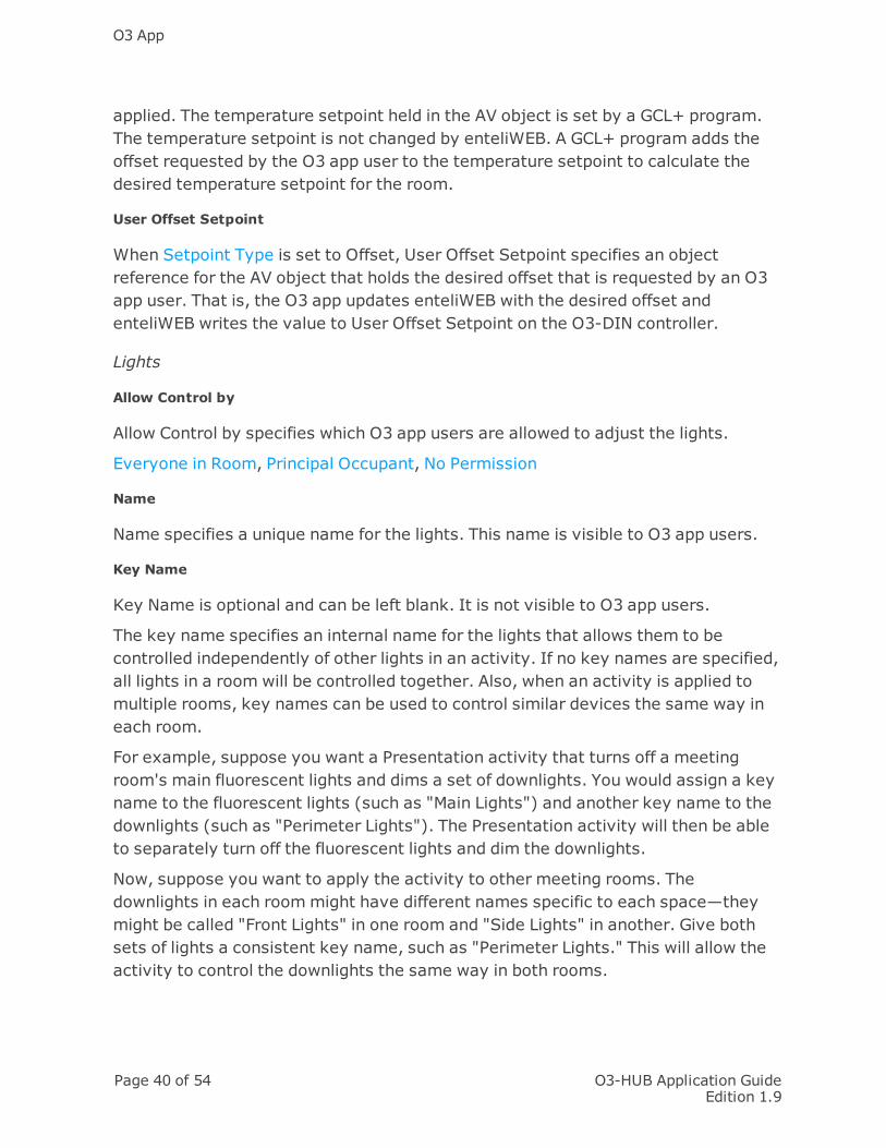
applied. The temperature setpoint held in the AV object is set by a GCL+ program.The temperature setpoint is not changed by enteliWEB. A GCL+ program adds theoffset requested by the O3 app user to the temperature setpoint to calculate thedesired temperature setpoint for the room.
User Offset Setpoint
When Setpoint Type is set to Offset, User Offset Setpoint specifies an objectreference for the AV object that holds the desired offset that is requested by an O3app user. That is, the O3 app updates enteliWEB with the desired offset andenteliWEB writes the value to User Offset Setpoint on the O3-DIN controller.
Lights
Allow Control by
Allow Control by specifies which O3 app users are allowed to adjust the lights.
Everyone in Room, Principal Occupant, No Permission
Name
Name specifies a unique name for the lights. This name is visible to O3 app users.
Key Name
Key Name is optional and can be left blank. It is not visible to O3 app users.
The key name specifies an internal name for the lights that allows them to becontrolled independently of other lights in an activity. If no key names are specified,all lights in a room will be controlled together. Also, when an activity is applied tomultiple rooms, key names can be used to control similar devices the same way ineach room.
For example, suppose you want a Presentation activity that turns off a meetingroom's main fluorescent lights and dims a set of downlights. You would assign a keyname to the fluorescent lights (such as "Main Lights") and another key name to thedownlights (such as "Perimeter Lights"). The Presentation activity will then be ableto separately turn off the fluorescent lights and dim the downlights.
Now, suppose you want to apply the activity to other meeting rooms. Thedownlights in each roommight have different names specific to each space—theymight be called "Front Lights" in one room and "Side Lights" in another. Give bothsets of lights a consistent key name, such as "Perimeter Lights." This will allow theactivity to control the downlights the same way in both rooms.

O3-HUB Application GuideEdition 1.9
Page 41 of 54
Control Type
Control Type specifies how the O3 app allows a user to control the lights.
l Dimmermeans the O3 app presents a dimmer to allows a user to control thelights.
l On/Offmeans the O3 app presents an on/off switch to allows a user to controlthe lights.
l Dimmer - On/Offmeans the O3 app presents both a dimmer and an on/offswitch to allows a user to control the lights.
Dimmer Reference
When Control Type is set to Dimmer or to Dimmer - On/Off , Dimmer Referencespecifies an object reference for the AV object that holds the dimmer setting.
Lights On Reference
When Control Type is set to On/Off or to Dimmer - On/Off , Lights On Referencespecifies an object reference for the BV object that causes the lights to be turnedon.
By design, Lights On Reference is always Off except momentarily when the lightsare turned on. For the current state of the lights, see State Reference.
Note: The BV object used for Lights On Reference should be different from the oneused for Lights Off Reference.
Lights Off Reference
When Control Type is set to On/Off or to Dimmer - On/Off , Lights Off Referencespecifies an object reference for the BV object that causes the lights to be turnedoff.
By design, Lights Off Reference is always Off except momentarily when the lightsare turned off. For the current state of the lights, see State Reference.
Note: The BV object used for Lights Off Reference should be different from the oneused for Lights On Reference.
State Reference
When Control Type is set to On/Off or to Dimmer - On/Off , State Referencespecifies an object reference for the BV object that holds the current state, On orOff, of the lights.

O3 App
Page 42 of 54 O3-HUB Application GuideEdition 1.9
Note: The BV object used for State Reference should be different from the onesused for Lights On Reference and Lights Off Reference.
For an on/off light switch, the Lights On Reference and Lights Off ReferenceBV objects are always Off except momentarily when the lights are turned onor off. State Reference remembers the lights on and off events to allow theO3 app to display the current state of the lights.
Blinds
Allow Control by
Allow Control by specifies the permission required for an O3 app user to adjust theblinds.
Everyone in Room, Principal Occupant, No Permission
Name
Name specifies a unique name for the blinds. This name is visible to O3 app users.
Key Name
Key Name is optional and can be left blank. It is not visible to O3 app users.
The key name specifies an internal name for the blinds that allows them to becontrolled independently of other blinds in an activity. If no key names are specified,all blinds in a room will be controlled together. Also, when an activity is applied tomultiple rooms, key names can be used to control similar devices the same way ineach room.
Position Reference
Position Reference specifies an object reference for the AV object that holds theposition of the blinds.
Angle Reference
Angle Reference specifies an object reference for the AV object that holds the angleof the blinds.
Fans
Allow Control by
Allow Control by specifies which O3 app users are allowed to adjust the fans.
Everyone in Room, Principal Occupant, No Permission

O3-HUB Application GuideEdition 1.9
Page 43 of 54
Name
Name specifies a unique name for the fan settings. This name is visible to O3 appusers.
Key Name
Key Name is optional and can be left blank. It is not visible to O3 app users.
The key name specifies an internal name for the fan setting that allows it to becontrolled independently of other fan settings in an activity. If no key names arespecified, all fans in a room will be controlled together. Also, when an activity isapplied to multiple rooms, key names can be used to control similar devices thesame way in each room.
Fan Reference
Fan Reference specifies an object reference for the MV object that holds the fanstate.
Activities
Activity Name
Activity Name lists the names of activities known to enteliWEB.
Enabled
When Enabled is selected, the corresponding activity is allowed in the room. WhenEnabled is not selected, the corresponding activity is not allowed in the room.
Principal Occupant
Users
Users lists the user names of users who are principal occupants of the room.
Groups
Groups lists the group names of groups whose members are principal occupants ofthe room.

O3 App
Page 44 of 54 O3-HUB Application GuideEdition 1.9
O3 Room Activity Concept
What is an O3 Room Activity?
An O3 room activity consists of a collection of comfort settings for an O3 roombased on what the occupants will be doing in the room: attending a meeting,attending a presentation, doing desk work, etc.
You can create multiple activities and associate an activity with multiple rooms.
An activity must include one or more of the following controls (depending on theoptions available in the O3-DIN controller and the sensor hub).
l Temperature setpoint
l Lights
l Blinds
l Fans
Activities and the O3 App
Using Delta Controls' O3 app, a room occupant with the proper permissions canchoose an activity for the room.
When the occupant chooses an activity, the app sends a request to enteliWEB andthe activity's definition is written to corresponding BACnet objects in the O3-DINcontroller that controls the room. The control sequence (implemented in GCL+ in thecontroller) adjusts the room's comfort settings accordingly.
When the occupant adjusts a setpoint, such as raising or lowering the roomtemperature, the app sends the change to enteliWEB and enteliWEB writes thechange to the appropriate BACnet object in the controller. The control sequence(implemented in GCL+ in the controller) adjusts the room's temperature settingaccordingly.
When an O3 app user selects an activity, all activity values are appliedregardless of the permission that the user has on each control.

O3-HUB Application GuideEdition 1.9
Page 45 of 54
Creating O3 Room Activities
An O3 room activity is a collection of comfort settings for an O3 room based aroundone or more setpoints (temperature, lights, blinds, etc.). An activity can be appliedto multiple rooms.
O3 room activities are created on the Create O3 Room Activity page ( >Systems and Dashboards > Rooms > Create O3 Room Activity).
To create an activity:
1. Enter the Activity Name (for example, "Presentation"). This name identifiesthe activity in enteliWEB. If Activity Label in App is left blank, it is also thename that is displayed in the app.
2. Optional: Enter the Activity Label in App (if you want it to be different from theActivity Name).
3. Select a Color to identify the activity in the app.
4. Optional: Enter a Description for the activity. The description is not visible tothe app user.
5. In the Activity Controls area:
a. On the Temperature tab, enter the Setpoint Value for the activity. Thisvalue is determined by the Setpoint Type (Absolute or Offset) of the O3room in which the activity takes place.
b. On the Lights tab, click Add, enter the desired light level for theactivity in the Dimmer field, then select the default On/Off setting (LightsOn, Lights Off, Not In Use). If applicable, enter its Key Name.
c. On the Blinds tab, click Add, enter the desired blind position for theactivity in the Position field (0% is fully retracted; 100% is fullydeployed), then enter the desired blind angle for the activity in the Anglefield (0° means slats pointed down; 90° means slats are horizontal; and180° means slats point up). If applicable, enter its Key Name.
d. On the Fans tab, click Add, then select the desired fan state for theactivity from the Fans list. This list of allowable fan states is determinedby the fan's MIC object. If applicable, enter its Key Name.
6. In the Rooms area, associate one or more rooms with the activity. ClickAdd, select a room from the list, then click OK. If the list is blank, then no

O3 App
Page 46 of 54 O3-HUB Application GuideEdition 1.9
rooms have been created yet. To create new rooms, see Creating O3 Rooms.
7. Click Create. The activity is added to the O3 Room Activities list.

O3-HUB Application GuideEdition 1.9
Page 47 of 54
Managing O3 Room Activities
An O3 room activity is a collection of comfort settings for an O3 room based aroundone or more setpoints (temperature, lights, blinds, etc.). An activity can be appliedto multiple rooms.
O3room activities are managed on the O3 Room Activities page ( > Systemsand Dashboards > Rooms > O3 Room Activities), which lists room activities forall sites known to enteliWEB.
Searching the Room Activities List
To search the room activities list, start typing a room activity name in the SearchRoom Activity field. The list is filtered as you type.
To see everything in the room activities list, clear the Search Room Activity field.
Sorting the Room Activities List
To sort the room activities list, click the column heading that you want to sort by.
Opening an Existing Room Activity
To open a room activity, click its name.
Adding a Room Activity
To add a new room activity, click Add. The Create O3 Room Activity page opens.For details, see Creating O3 Room Activities.
Copying a Room Activity
1. From the room activities list, select the activity that you want to copy.
2. Click Copy . The Copy Room Activity dialog opens.
3. Edit the Activity Name as needed. Each activity name must be unique.
4. If you don't want to keep the associated rooms with the new activity, clear theCopy Room Mapping checkbox.
5. Click Copy. The room activity list is updated to include the copied activity.
Setting the Units for Room Activities
Changes to the room activity unit settings apply to all room activities.

O3 App
Page 48 of 54 O3-HUB Application GuideEdition 1.9
1. Click Settings. The Activity Unit Settings dialog opens.
2. To set the temperature unit, select °C or °F from the Temperature list.
3. To set the fan unit, in the Fan field, enter the MIC object that holds the list ofallowed fan states. The MIC object must be from version 4 firmware.
4. To set the blind angle unit, select % or ° from the Blind Angle list.
5. Click Save to apply the settings.
Deleting a Room Activity
1. From the room activities list, select the activity or activities that you want todelete.
2. Click Delete. A confirmation dialog opens.
3. Click Yes to delete the activities.

O3-HUB Application GuideEdition 1.9
Page 49 of 54
O3 Room Activity Configuration Reference
Configuration
Activity Name
Activity Name specifies the name used in enteliWEB for this activity. When ActivityLabel in App is blank, then Activity Name is displayed in the O3 app.
Activity Label in App
Activity Label in App specifies the name used in the O3 app for this activity. WhenActivity Label in App is blank, then Activity Name is displayed in the O3 app.
Color
Color specifies the color that you want to associate with the activity to help usersidentify it in the O3 app.
Description
Description contains a brief description of the activity to help you identify it. Thedescription is not visible to O3 app users.
Activity Controls
Temperature
Setpoint Value
The setpoint value is determined by the setpoint type (absolute or offset) that hasbeen configured for the room in which the activity takes place.
Setpoint Type = Absolute
When the setpoint type is absolute, the setpoint value specifies the temperaturesetpoint for the room when the activity is selected by an O3 app user (for example,19°C). The setpoint value must be in the range for the absolute temperatureconfigured for the room by the Minimum Value and Maximum Value settings. Thetemperature setpoint is written to the object specified by the Setpoint Reference.
Setpoint Type = Offset
When the setpoint type is offset, the setpoint value specifies the temperature offsetfor the room that is applied when the activity is selected by an O3 app user (forexample, -1 or +2). The setpoint value must be in the range for the offset that is

O3 App
Page 50 of 54 O3-HUB Application GuideEdition 1.9
configured for the room by the Offset Adjustment (+/-) setting. The offset is appliedto the value held by the Base Setpoint Reference.
Lights
Key Name
Key Name is optional and can be left blank. It is not visible to O3 app users.
The key name specifies an internal name for the lights that allows them to becontrolled independently of other lights in an activity. If no key names are specified,all lights in a room will be controlled together. When an activity is applied to multiplerooms, key names can be used to control similar devices the same way in eachroom.
Dimmer
Dimmer specifies the desired light level (as a percentage) when this activity isselected by an O3 app user.
On/Off
On/Off specifies whether the room lights are on or off by default, when this activityis selected by an O3 app user.
l Lights On specifies that the lights are on.
l Lights Off specifies that the lights are off.
l Not In Use specifies that the activity does not include light control.
Blinds
Key Name
Key Name is optional and can be left blank. It is not visible to O3 app users.
The key name specifies an internal name for the blinds that allows them to becontrolled independently of other blinds in an activity. If no key names are specified,all blinds in a room will be controlled together. When an activity is applied tomultiple rooms, key names can be used to control similar devices the same way ineach room.
Position
Position specifies the desired height of the blinds when this activity is selected by anO3 app user.

O3-HUB Application GuideEdition 1.9
Page 51 of 54
l 0% specifies that the blinds are fully retracted or rolled up.
l 100% specifies that the blinds are fully deployed or rolled down.
Angle
Angle specifies the desired angle of the slats when this activity is selected by an O3app user.
l 0° specifies that the blinds are fully closed with the slats pointing down.
l 90° specifies that the blinds are fully open with the slats horizontal.
l 180° specifies that the blinds are fully closed with the slats pointing up.
Fans
Key Name
Key Name is optional and can be left blank. It is not visible to O3 app users.
The key name specifies an internal name for the fan setting that allows it to becontrolled independently of other fan settings in an activity. If no key names arespecified, all fans in a room will be controlled together. When an activity is applied tomultiple rooms, key names can be used to control similar devices the same way ineach room.
Fans
Fans specifies the state of the fan operation. The list of allowed states is taken fromthe MIC object specified for Fan in the Activity Unit Settings dialog on the O3 RoomActivities page. See Selecting the Units for Room Activities.

O3 App
Page 52 of 54 O3-HUB Application GuideEdition 1.9
Deploying the O3 App for Building Occupants
The O3 app allows occupants with the proper permissions to control the comfortsettings of a room by interacting with enteliWEB, an O3-DIN controller, and a sensorhub.
To use the O3 app, occupants must log in with either an enteliWEB account or aGoogle Account (Gmail address). Both login methods are valid on Android and iOSmobile devices.
Users with a Google Account
When a user logs in to the O3 app for the first time with a Google Account,enteliWEB creates a guest account for the user and assigns them to the O3 RoomGuests group—provided the automatic guest user creation function is enabled. To
enable this function, go to > Configuration> Global Settings and select theEnable Automatic Creation of Guest User Account checkbox.
The O3 Room Guests group is created automatically in enteliWEB and includes thenecessary object, service, and device permissions to use the O3 app. To view or edit
the group’s settings, go to > Sites and Users > Groups and click O3 RoomGuests.
As long as the O3 room control permissions are set to Everyone in Room, users withGoogle Accounts should be able to see rooms and control setpoints and comfortsettings when they log in to the app.
Users with an enteliWEB Account
Users with non-administrator enteliWEB accounts can log in to the O3 app with theirenteliWEB account credentials but they will not be able to see rooms and controlsetpoints and comfort settings unless they are assigned to the O3 Room Guestsgroup or to another group with the same object, service, and device permissions.
To add an enteliWEB user to the O3 Room Guests group:
1. Go to > Sites and Users > Groups and click O3 Room Guests.
2. In the Members area, click Edit. The Edit Membership dialog opens and liststhe usernames of all users.
3. In the Search field, enter the username of the user you want to add and pressEnter. The username is shown in the list of users.
4. Select the user and click Save.

O3-HUB Application GuideEdition 1.9
Page 53 of 54
To create a group based on the O3 Room Guests group:
1. Go to > Sites and Users > Groups and click O3 Room Guests.
2. Scroll to the bottom of the page and click Copy Group. The Copy Group dialogopens.
3. Enter a new name for the group and click Create. The new group will have thesame permissions as the O3 Room Guests group.
4. Configure other settings for the group as needed.
5. Add members to the group.
As long as the O3 room control permissions are set to Everyone in Room, users withenteliWEB accounts that are members of the O3 Room Guests group (or anothergroup with the same permissions as the O3 Room Guests group) should be able tosee rooms and control setpoints and comfort settings when they log in to the app.

Document Revision History
Page 54 of 54 O3-HUB Application GuideEdition 1.9
Document Revision History
Edition Date Change Description1.0 August 2018 First publication.1.1 September 2018 Updated object descriptions AI30s000,
BI30s002, BI30s003, AI30s007 throughAI30s009, and AV30s005.
1.2 September 2018 Added note regarding range limitation forcustom value object instances.
1.3 September 2018 In the sections about the O3 room tasksand activities, added a new section called"Before you begin" that describes therequirements to set up O3 rooms.
1.4 October 2018 Corrected temperature sensor instancenumber on page 11.
1.5 November 2018 Corrected description of BV30s026 object.1.6 February 2019 Updated O3 app documentation.1.7 March 2019 Added reference to the Database Creation
tool.1.8 August 2019 Updated object list for 2xP variants, added
procedure for loading custom sounds,reorganized document layout.
1.9 September 2019 Revised section on adding custom sounds.