preliminary safety analysis report · safety analysis report i j volume 16 project management...
TRANSCRIPT

CLINCHK RIVER
BREEDER REACTOR PROJECT
PRELIMINARYSAFETY ANALYSIS
REPORT
I
J
VOLUME 16
PROJECT MANAGEMENT CORPORATION
it

TABLE OF CONTENTS
Section
1.0 INTRODUCTION AND GENERAL DESCRIPTION OF THE PLANT 1.1-1
1.1 INTRODUCTION 1.1-1
1.1-.1 General Information 1.1-21.1.2 Overview of Safety Design Approach 1.1-31.1.3 Applicability of Regulatory Guides 1.1-5
1.2 GENERAL PLANT DESCRIPTION 1.2-1
1.2.1 Site 1.2-11.2.2 Engineered Safety Features 1.2-21.2.3 Reactor, Heat Transport and Related Systems 1.2-21.2.4 Steam Generator - Turbine and Related Systems 1.2-31.2.5 OffsIte and Onsite Power 1.2-51.2.6 Instrumentation, Control and Protection 1.2-61.2.7 Auxiliary Systems 1.2-71.2.8 Refueling System 1.2-81.2.9 Radwaste Disposal System 1.2-91.2.10 Reactor Conf i nement/Contai nment System 1.2-91.2.11 Major Structures 1.2-10
1.3 COMPARISON TABLES 1.3-1
1.3.1 Comparisons with Similar Designs 1.3-11.3.2 Detailed Comparison with Fast Flux Test Facility 1.3-2
1.4 IDENTIFICATION OF PROJECT PARTICIPANTS 1.4-1
1.4.1 Functions, Responsibilities and Authorities ofProject Participants 1.4-2
1.4.2 Descript.lon of Organizations 1.4-31.4.3 Interrelationships with Contractors and Suppliers 1.4-21a1.4.4 General Qualification Requirement of CRBRP
Project Participants 1.4-22
1.5 REQUIREMENTS FOR FURTHER TECHNICAL INFORMATION 1.5-1
1.5.1 Information Concerning the Adequacy of a NewDes!ign 1.5-2
1.5.2 Information Concerning Margin of Conservatism ofProven Design 1.5-28
1.5.3 References 1.5-47
Amend. 68May 1982

TABLE OF CONTENTS (Cont'd.)
Sect I on
1.6 MATERIAL INCORPORATED BY REFERENCE 1.6-1
1.6.1 Introduction 1.6-11.6.2 References 1.6-1
'Appendix 1-A Flow Diagram Symbols I.A-I
2.0 SITE CHARACTERISTICS 2.1-1
2.1 GEOGRAPHY AND DEMOGRAPHY 2.1-1
2.1.1 Site Location and Layout 2.1-12.1.2 Site Description 2.1-22.1.3 Population and Population Distribution 2.1-42.1.4 Uses of Adjacent Lands and Waters 2.1-8
2.2 NEARBY INDUSTRIAL. TRANSPORTATION AND MILITARYFACILITIES 2.2-1
2.2.1 Locations, Routes, and Descriptions 2.2-12.2.2 Evaluations 2.2-32.2.3 New Facility/Land Use Requirements 2.2-4c
2.3 METEOROLOY 2.3-1
2.3.1 Regional Climatology 2.3-12.3.2 Local Meteorology 2.3-42.3.3 On-site Meteorological Monitoring Program 2.3-92.3.4 Short-Term (Accident) Diffusion Estimates 2.3-92.3.5 Long-Term (Average) Diffusion Estimates 2.3-13
2.4 HYDROLOGIC ENGINEERING 2.4-I
2.4.1 Hydrologic Description 2.4-12.4.2 Floods 2.4-62.4.3 Probable Maximum Flood (PMF) on Streams and
Rivers 2.4-102.4.4 Potential Dam Failures (Selsmically and
Otherwise Induced) 2.4-212.4.7 Ice Flooding 2.4-312.4..8 Cooling Water Canals and Reservoirs 2.4-31a2.4.9 Channel Diversions 2.4-322.4.10 Flooding Protection Requirements 2.4-322.4.11 Low Water Considerations 2.4-332.4.12 Environmental Acceptance of Effluents 2.4-422.4.13 Groundwater 2.4-442.4.14 Technical Specification and Emergency Operation
RequIrement 2.4-55
Amend. 68May 1982

TABLE OF CONTENTS (Cont'd.)
Section Rao
2.5 GEOLOGY AND SEISMOLOGY 2.5-1
2.5.1 Basic Geologic and Seismic Information 2.5-12.5.2 Vibratory Ground Motion 2.5-202.5.3 Surface Faulting 2.5-272.5.4 Stability of Subsurface Materials 2.5-322.5.5 Slope Stability 2.5-48a
Appendix 2-A Field Investigative Procedures 2A-1Appendix 2-B Laboratory Test Procedures 2B-1Appendix 2-C Report of Test Grouting Program 2C-1Appendix 2-D Report of Engineering Propertiesfor Crushed Stone Materials from CommercialSuppliers 2D-1Appendix 2-E Extracts from U.S. AtomicEnergy Commission AEC Manual 2E-1
Supplement 1 to Chapter 2 Deleted
Supplement 2 to Chapter 2 Question and ResponsesRelated to Chapter Two Information and CriticalFor NRC Docketing of CRBRP Environmental Report I
3.0 DESIGN CRITERIA - STRUCTURES., COMPONENTS EQUIPMENT
ANDSYSTEMS 3.1-1
3.1 CONFORMANCE WITH GENERAL DESIGN CRITERIA 3.1-1
3.1.1 Introduction and Scope 3.1-13.1.2 Definitions and Explanations 3.1-23.1.3 Conformance with CRBRP General Design Criteria 3.1-8
3.2 CLASSIFICATIONS OF STRUCTURES,. SYSTEMS,AND COMPONENTS 3.2-1
3.2.1 Seismic Classifications 3.2-13.2.2 Safety Classifications 3.2-2
3.3 WIND AND TORNADO LOADINGS 3.3-1
3.3.1 Wind Loadings 3.3-13.3.2 Tornado Loadings 3.3-2
3.4 WATER LEVEL (FLOOD) DESIGN 3.4-1
3.4.1 Flood Protection 3.4-13.4.2 Analysis Procedures 3.4-la
III Amend. 68May 1982
TABLE OF CONTENTS :(Cont'd.)
.SectIonE
3.5 MISSILE PROTECTION 3.5-1
3.5.1 Missile Barrier and Loadings 3.5-43.5.2 Missile Selection 3.5-4a3.5.3 Selected Missiles 3.5-73.5.4 Barrier Design Procedures 3.5-103.5.5 Missile Barrier Features 3.5-13c
3.6 PROTECTION AGAINST DYNAMIC EFFECTS ASSOCIATEDWITH THE POSTULATED RUPTURE OF PIPING 3.6-1
3.6.1 Systems In Which Pipe Breaks are Postulated 3.6-13.6.2 Pipe Break Criteria 3.6-23.6.3 Design Loading Combinations 3.6-23.6.4 Dynamic Analysis 3.6-33.6.5 Protective Measures 3.6-8
3.7 SEISMIC DESIGN 3.7-1
3.7.1 Seismic Input 3.7-13.7.2 Seismic System Analysis 3.7-4a3.7.3 Seismic Subsystem Analysis 3.7-113.7.4 Seismic Instrumentation Program 3.7-163.7.5 Seismic Design Control 3.7-20
Appendix to Section 3.7 Seismic Design Criteria 3.7-A.1
3.8 DESIGN OF CATEGORY I STRUCTURES 3.8-1
3.8.1 Concrete Containment (Not Applicable) 3.8-13.8.2 Steel Containment System 3.8-13.8.3 Concrete and Structural Steel Internal
Structures of Steel Containment 3.8-83.8.4 Other Seismic Category I Structures 3.8-22a3.8.5 Foundation and Concrete Supports 3.8-35
Appendix 3.8A Buckling Stress Criteria 3.8A-1Appendix 3.8-B Cell Liner Design Criteria 3.8-B.1Appendix 3.8-C Catch Pan and Fire SuppressionDeck Design Criteria 3.8-C.1
3.9 MECHANICAL SYSTEMS AND COMPONENTS 3.9-1
3.9.1 Dynamic System Analysis and Testing 3.9-13.9.2 ASME Code Class 2 and 3 Components 3.9-3a3.9.3 Components Not Covered by ASME Code 3.9-5
3.10 SEISMIC DESIGN OF CATEGORY I INSTRUMENTATIONAND ELECTRICAL EQUIPMENT 3.10-1
3.10.1 Seismic Design Criteria 3.10-1
Iv Amend. 68
May 1982

TABLE OF CONTENTS (Contld..)
Sect I on
3.10.2
3.11
3.11.13.11.23.11.33.11.43.11.5
3A. 0
3A. 13A. 23A. 33A. 43A. 53A. 63A. 73A. 8
4.0
4.1
Analysis, Testing Procedures and RestraintMeasures
ENVIRONMENTAL DESIGN OF MECHANICAL ANDELECTRICAL EQUIPMENT
Equipment IdentificationQualification Test and AnalysisQualification Test ResultsLoss of VentilationSpecial Considerations
SUPPLEMENTARY INFORMATION ON SEISMIC CATEGORY ISTRUCTUIRES
Inner Cell SystemHead Access AreaControl BuildingReactor Service Building (RSB)Steam Generator BuildingDiesel Generator BuildingDeletedCell Liner Systems
REACTOR
SUMMARY DESCRIPTION
Lower InternalsUpper InternalsCore RestraintFuel Blanket and Removable Radial Shield RegionsDesign and Performance CharacteristicsLoading Conditions and Analysis TechniquesComputer Codes
MECHANICAL DESIGN
Fuel and Blanket DesignReactor Vessels InternalsReactivity Control Systems
3.10-3
3.11-1
3.11-13.11-13.11-13.11-23.11-2
3A. 1-1
3A. 1-13A. 2-13A. 3-13A.4-13A. 5-13A. 6-1
3A.8-1
4.1-1
4.1-1
4.1-14.1-34.1-44.1-44.1-94.1-94.1-10
4.2-1
4.2-14.2-1184.2-228
4.3-1
4.3-14.3-34.3-69
4.1.14.1.24.1.34.1.44.1.54.1.6
4.1.74.2
I
4.2.14.2.24.2.3
4.3 NUCLEAR DESIGN
4.3.14.3.24.3.34.3.4
Design BasesDescriptionAnalytical MethodsChangesr
VAmend. 68May 1982

TABLE OF CONTENTS (Cont'd.)
Section
4.4 THERMAL AND HYDRAULIC DESIGN 4.4-1
4.4.1 Design Bases 4.4-14.4.2 Description 4.4-44.4.3 Evaluation 4.4-454.4.4 Testing and Verification 4.4-754.4.5 Core Instrumentation 4.4-80
5.0 HEAT TRANSPORT AND CONNECTED SYSTEMS 5.1-1
5.1 SUMMARY DESCRIPTION 5.1-1a
5.1.1 Reactor Vessel, Closure Head, and Guard Vessel 5.1-1a5.1.2 Primary Heat Transport System 5.1-25.1.3 Intermediate Heat Transport System 5.1-55.1.4 Steam Generator System 5.1-75.1.5 Residual Heat Removal System 5.1-85.1.6 Auxiliary Liquid Metal System 5.1-95.1.7 Features for Heat Transport System Safety 5.1-105.1.8 Physical Arrangement 5.1-11
5.2 REACTOR VESSEL. CLOSURE HEAD. AND GUARD VESSEL 5.2-1
5.2.1 Design Basis 5.2-15.2.2 Design Parameters 5.2-4b5.2.3 Special Processes for Fabrication and Inspection 5.2-75.2.4 Features for Improved Reliability 5.2-85.2.5 Quality Assurance Surveillance 5.2-10d5.2.6 Materials and Inspections 5.2-115.2.7 Packing, Packaging, and Storage 5.2-11a
Appendix 5.2.A Modifications to the High Temp-erature Design Rules for Austenitic Stainless Steel 5.2A-1
5.3 PRIMARY HEAT TRANSPORT SYSTEM (PHTS) 5.3-1
5.3.1 Design Bases 5.3-15.3.2 Design Description 5.3-95.3.3 Design Evaluation 5.3-335.3.4 Tests and Inspections 5.3-72
5.4 INTERMEDIATE HEAT TRANSPORT SYSTEM (IHTS) 5.4-1
5.4.1 Design Basis 5.4-15.4.2 Design Description 5.4-65.4.3 Design Evaluation 5.4-12
viAmend. 68May 1982

TABLE OF CONTENTS (Cont'd.)
SectIon
5.5 STEAM GENERATOR SYSTEM (SGS) 5.5-1
5.5.1 Design Bases 5.5-15.5.2 Design Description 5.5-55.5.3 Design Evaluation 5.5-17
5.6 RESIDUAL HEAT REMOVAL SYSTEMS 5.6-1
5.6.1 Steam Generator Auxiliary Heat RemovalSystem (SGAHRS) 5.6-lb
5.6.2 Direct Heat Removal Service (DHRS) 5.6-20
5.7 OVERALL HEAT TRANSPORT SYSTEM EVALUATION 5.7-1
5.7.1 Startup and Shutdown 5.7-15.7.2 Load Following Characteristics 5.7-25.7.3 Transient Effects 5.7-2a5.7.4 Evaluation of Thermal Hydraulic Characteristics
and Plant Design Heat Transport System Design 5.7-6Transient Summary
6.0 ENGINEERED SAFETY FEATURES 6.1-1
6.1 GENERAL 6.1-1
6.2 CONTAINMENT SYSTEMS 6.2-1
6.2.1 Confinement/Containment Functional Design 6.2-16.2.2 Containment Heat Removal 6.2-96.2.3 Containment Air Purification and Cleanup System 6.2-96.2.4 Containment Isolation Systems 6.2-106.2.5 Annulus Filtration System 6.2-146.2.6 Reactor Service Building (RSB) Filtration System 6.2-166.2.7 Steam Generator Building Aerosol Release
Mitigation System Functional Design 6.2-17
6.3 HABITABILITY SYSTEMS 6.3-1
6.3.1 Habitability System Functional Design 6.3-1
6.4 CELL LINER SYSTEM 6.4-1
6.4.1 Design Base 6.4-16.4.2 System Design 6.4-16.4.3 Design Evaluation 6.4-16.4.4 Tests and Inspections 6.4-16.4.5 Instrumentation Requirements 6.4-1
viiAmend. 68May 1982

TABLE OF CONTENTS (Cont'd.)
Sect IonRA
6.5 CATCH PAN 6.5-1
6.5.1 Design Base 6.5-16.5.2 System Design Description and Evaluation 6.5-16.5.3 Tests and Inspections 6.5-16.5.4 Instrumentation Requirements 6.5-1
7.0 INSTRUMENTATION AND CONTROLS 7.1-1
7.1 INTRODUCTION 7.1-1
7.1.1 Identification of Safety Related Instrumentationand Control Systems 7.1-1
7.1.2 Identification of Safety Criteria 7.1-1
7.2 REACTOR SHUTDOWN SYSTEM 7.2-1'
7.2.1 Description 7.2-17.2.2 Analysis 7.2-13
7.3 ENGINEERED SAFETY FEATURE INSTRUMENTATION ANDCONTROL 7.3-1
7.3.1 Containment Isolation System 7.3-17.3.2 Analysis 7.3-3
7.4 INSTRUMENTATION AND CONTROL SYSTEMS REQUIRED FORSAFE SHUTDOWN 7.4-1
7.4.1 Steam Generator Auxiliary Heat RemovalInstrumentation and Control Systems 7.4-1
7.4.2 Outlet Steam Isolation Instrumentation andControl System 7.4-6
7.4.3 Remote Shutdown System 7.4-8a
7.5 INSTRUMENTATION AND MONITORING SYSTEM 7.5-1
7.5.1 Flux Monitoring System 7.5-17.5.2 Heat Transport Instrumentation System 7.5-57.5.3 Reactor and Vessel Instrumentation 7.5-137.5.4 Fuel Failure Monitoring System 7.5-147.5.5 Leak Detection Systems 7.5-187.5.6 Sodium-Water Reaction Pressure Relief System
(SWRPRS) Instrumentation and Controls 7.5-307.5.7 Containment Hydrogen Monitoring 7.5-33b7.5.8 Containment Vessel Temperature Monitoring 7.5-33b7.5.9 Containment Pressure Monitoring 7.5-33b7.5.10 Containment Atmosphere Temperature 7.5-33c7.5.11 Post Accident Monitoring 7.5-33c
villAmend. 68May 1982

TABLE OF CONTENTS (Cont'd.)
Sect Ion
7.6
7.6.1
7.6.27.6.3
7.6.4
7.6.5
7.7
7.7.1
7.7.2
7.8
7.8.17.8.2
7.9
OTHER INSTRUMENTATION AND CONTROL SYSTEMS REQUIREDFORSAETY
Plant Service Water and Chilled WaterInstrumentation and Control SystemsDeletedDirect Heat Removal Service (DHRS)Instrumentation and Control SystemHeating, Ventilating, and Air ConditioningInstrumentation and Control SystemSGB Flooding Protection Subsystem
INSTRUMENTATION AND CONTROL SYSTEMS NOT REQUIREDFORSAFETY
Plant Control System DescriptionDesign Analysis
PLANT DATA HANDLING AND DISPLAY SYSTEM
Design DescriptionDesign Analysis
OPERATING CONTROL STATIONS
Design BasisControl RoomLocal Control StationsCommunicationsDesign Evaluation
ELECTRIC POWER
INTRODUCTION
Utility Grid and InterconnectionsPlant Electrical Power SystemCriteria and Standards
OFFSITE POWER SYSTEM
DescriptionAnalysis
ON-SITE POWER SYSTEMS
AC Power SystemsDC Power System
7.6-1
7.6-1
7.6-3
7.6-3e7.6-3f
7.7-1
7.7-17.7-16
7.8-1
7.8-17.8-2
7.9-1
7.9-17.9-17.9-67.9-67.9-6
8.1-1
8.1-1
8.1-18.1-18. 1-3
8.2-1
8.2-18.2-4
8.3-1
8.3-18.3-44
7.9.17.9.27.9.37.9.47.9.5
8.0
8.1
8.1.18.1.28.1.3
8.2
8.2.18.2.2
8.3
8.3.18.3.2I
IxAmend. 68May 1982

TABLE OF CONTENTS (Cont'd.)
Section
9.0
9.1
9.1 .19.1.29.1.39.1.4
AUXILIARY SYSTEMS
FUEL STORAGE AND HANDLING
I 9.2
9.2.19.2.29.2.39.2-49.2-5
9.3
9.3.19.3.29.3.39.3.49.3.5
9.4
9.4.19.4.29.4.39.4.49.4.5
9.5
New Fuel StorageSpent Fuel StorageSpent Fuel Cooling and Cleanup SystemFuel Handling System
NUCLEAR ISLAND GENERAL PURPOSEMAINTENANCE SYSTEM
Design BasisSystem DescriptionSafety EvaluationTests and InspectionsInstrumentation Applications
AUXILIARY LIQUID METAL SYSTEM
Sodium and NaK Receiving SystemPrimary Na Storage and ProcessingEVS Sodium ProcessingPrimary Cold Trap NaK Cooling SystemIntermediate Na Processing System
PIPING AND EQUIPMENT ELECTRICAL HEATING
Design BasesSystems DescriptionSafety EvaluationTests and InspectionsInstrumentation Application
INERT GAS RECEIVING AND PROCESSING SYSTEM
Argon Distribution SubsystemNitrogen Distribution SystemSafety EvaluationTests and InspectionsInstrumentation Requirements
HEATING. VENTILATING• AND AIR CONDITIONING SYSTEM
9.3-1
Page
9.1-1
9.1-1
9.1-39.1-59.1-209.1-33
9.2-1
9.2-19.2-19.2-39.2-39.2-4
9.3-1 a9.3-29.3-9a9.3-109..3-12
9.4-1
9.4-19.4-29.4-39.4-3b9.4-3b
9.5-1
9.5.19.5.29.5.39.5.49.5.5
9.6
9.6.19.6.29.6.39.6.49.6.59.6.6
Control Building HVAC SystemReactor Containment BuildingReactor Service Building HVAC SystemTurbine Generator Building HVAC SystemDiesel Generator Building HVAC SystemSteam Generator Building HVAC System
x
9.5-29.5-69.5-109.5-129.5-12
9.6-1
9.6-19.6-129.6-259.6-379.6-409.6-45
Amend. 68May 1982

TABLE OF CONTENTS (Cont'd.)
SectIon
9.7 CHILLED WATER SYSTEMS 9.7-1
9.7.1 Normal Chilled Water System 9.7-1.9.7.2 Emergency Chilled Water System 9.7-49.7.3 Prevention of Sodium or NaK/Water Interactions 9.7-99.7.4 Secondary Coolant Loops (SCL) 9.7-12
9.8 IMPURITY MONITORING AND ANALYSIS SYSTEM 9.8-1
9.8.1 Design Basis 9.8-19.8.2 Design Description 9.8-29.8.3 Design Evaluation 9.8-59.8.4 Tests and Inspection 9.8-79.8.5 Instrumentation Requirements 9.8-8
9.9 SERVICE WATER SYSTEMS 9.9-1
9.9.1 Normal Plant Service Water System 9.9-19.9.2 Emergency Plant Service Water System 9.9-29.9.3 Secondary Service Closed Cooling Water System 9.9-49.9.5 River Water Service 9.9-11
9.10 COMPRESSED GAS SYSTEM 9.10-1
9.10.1 Service Air and Instrument Air Systems 9.10-19.10.2 Hydrogen System 9.10-3a9.10.3 Carbon Dioxide System 9.10-4
9.11 COMMUNICATIONS SYSTEM 9.11-1
9.11.1 Design Bases 9.11-19.11.2 Description 9.11-3
9.12 LIGHTING SYSTEMS 9.12-1
9.12.1 Normal Lighting System 9.12-19.12.2 Standby Lighting Systems 9.12-29.12.3 Emergency Lighting System 9.12-39.12.4 Design Evaluation 9.12-4
9.13 PLANT FIRE PROTECTION SYSTEM 9.13-1
9.13.1 Non-Sodium Fire Protection System 9.13-19.13.2 Sodium Fire Protection System (SFPS) 9.13-139.13A Overall Fire Protection Requirements-- CRBRP
Design Compared with APCSB 9.5-1 & ASB 9.5-1 9.13A-1
9.14 DIESEL GENERATOR AUXILIARY SYSTEM 9.14-1
9.14.1 Fuel Oil Storage and Transfer System 9.14-1
xi Amend. 68
May 1982

TABLE OF CONTENTS (Cont'd.)
9.14.2 Cooling Water System 9.14-29.14.3 Starting Air Systems 9.14-49.14.4 Lubrication System 9.14-5
9.15 EQUIPMENT AND FLOOR DRAINAGE SYSTEM 9.15-1
9.15.1 Design Bases 9.15-19.15.2 System Description 9.15-19.15.3 Safety Evaluation 9.15-29.15.4 Tests and Inspections 9.15-29.15.5 Instrumentation Application 9.15-2
9.16 RECIRCULATION GAS COOLING SYSTEM 9.16-1
9.16.1 Design Basis 9.16-19.16.2 System Description 9.16-19.16.3 Safety Evaluation 9.16-69.16.4 Tests and Inspection 9.16-79.16.5 Instrumentation and Control 9.16-7
10.0 STEAM AND POWER CONVERSION SYSTEM 10.1-1
10.1 SUMMARY DESCRIPTION 10.1-1
10.2 TURBINE GENERATOR 10.2-1
10.2.1 Design Bases 10.2-110.2.2 Description 10.2-1a10.2.3 Turbine Missiles 10.2-510.2.4 Evaluation 10.2-9
10.3 MAIN STEAM SUPPLY SYSTEM 10.3-1
10.3.1 Design Bases 10.3-110.3.2 Description 10.3-110.3.3 Evaluation 10.3-210.3.4 Inspection and Testing Requirements 10.3-210.3.5 Water Chemistry 10.3-3
10.4 OTHER FEATURES OF STEAM AND POWER CONVERSIONSYSTEM 10.4-1
10.4.1 Condenser 10.4-110.4.2 Condenser Air Removal System 10.4-210.4.3 Turbine Gland Sealing System 10.4.310.4.4 Turbine Bypass System 10.4-410.4.5 Circulating Water System 10.4-510.4.6 Condensate Cleanup System 10.4-7
xil
Amend. 68May 1982

TABLE OF CONTENTS (Cont'd.)
five
10.4.710.4.8
11.0
11.1
11.1.111.1.211.1.311.1.411.1.5
11.1.6
11.2
11.2.111.2.211.2.311.2.411.2.511.2.611.2.711.2.8
11.3
Condensate and Feedwater SystemsSteam Generator Blowdown System
RADIOACTIVE WASTE MANAGEMENT
10.4-910.4-1 4
11.1-1
SOURCE TERMS
Modes of Radioactive Waste ProductionActivation Product Source Strength ModelsFission Product and Plutonium Release ModelsTritium Production SourcesSummary of Design Bases for Deposition ofRadioactivity In Primary Sodium on Reactor andPrimary Heat Transfer Surfaces and WithinReactor Auxiliary SystemsLeakage Rates
I IIIID WASTE SYSTEM
11.1-2
11.1-511 .1-211.1-511 .1-7
11.1-7
11.1-10
11.2-2
11.2-411.2-211.2-411.2-511.2-611.2-61.1.2-711.2-8
11 .2A-1
11.3-1
Design ObjectivesSystem DescriptionSystem DesignOperating Procedures and Performance TestsEstimated ReleasesRelease PointsDilution FactorsEstimated DosesAppendix 11.2A Dose Models: Liquid Effluents
GASEOUS WASTE SYSTEM
11.3.111.3.211.3.311.3.411.3.511.3.611.3.711.3.8
11.4
Design Base 11.3-1System Description 11.3-1System Design 11.3-1Operating Procedures and Performance Tests 11.3-1Estimated Releases 11.3-1Release Points 11.3-1Dilution Factors 11.3-1Dose Estimates 11.3-1Appendix 11.3A Dose Models: Gaseous Effluents 11.3A-
PROCESS AND EFFLUENT RADIOLOGICAL MONITORING SYSTEM 11.4-71
0la45771
I11.4.111.4.211.4.3
Design Objectives 11.4-1Continuous Monitoring/Sampling 11.4-2Sampling 11.4-3
xlii Amend. 68
May 1982

TABLE OF CONTENTS (Cont'd.)
11.5 SOLID WASTE SYSTEM 11.5-1
11.5.1 Design Objectives 11.5-111.5.2 System Inputs 11.5-111.5.3 Equipment Description 11.5-111.5.4 Expected Volumes 11.5-311.5.5 Packaging 11.5-411.5.6 Storage Facilities 11.5-411.5.7 Shipment 11.5-4
11.6 OFFSITE RADIOLOGICAL MONITORING PROGRAM 11.6-1
11.6.1 Expected Background 11.6-111.6.2 Critical Pathways to Man 11.6-211.6.3 Sampling Media, Locations and Frequencies 11.6-411.6.4 Analytical Sensitivity 11.6-411.6.5 Data Analysis and Presentation 11.6-411.6.6 Program Statistical Sensitivity 11.6-5
12.0 RADIATION PROTECTION 12.1-1
12.1 SHIELDING 12.1-1
12.1.1 Design Objectives 12.1-112.1.2 Design Description 12.1-312.1.3 Source Terms 12.1-1312.1.4 Area Radiation Monitoring 12.1-2312.1.5 Estimates of Exposure 12.1-24
Appendix to Section 12.1 12.1A-1
12.2 VjEjILAT 12.2-1
12.2.1 Design Objectives 12.2-112.2.2 Design Description 12.2-112.2.3 Source Terms 12.2-312.2.4 Airborne Radioactivity Monitoring 12.2-312.2.5 Inhalation Doses 12.2-5
12.3 HEALTH PHYSICS PROGRAM 12.3-1
12.3.1 Program Objectives 12.3-112.3.2 Facilities and Equipment 12.3-312.3.3 Personnel Dosimetry 12.3-612.3.4 Estimated Occupancy Times 12.3-7
Appendix 12A - Information Related to ALARA for 12A-1Occupational Radiation Exposures
xivAmend. 68May 1982

TABLE OF CONTENTS (Contld.)
SectI on
13.0 CONDUCT OF OPERATIONS 13.1-I
13.1 ORGANIZATIONAL STRUCTURE OF THE APPLICANT 13.1-1
13.1.1 Project Organization 13.1-113.1.2 Operating Organization 13.1-513.1.3 Qualification Requirements for Nuclear Plant
Personnel 13.1-12
13.2 TRAINING PROGRAM 13.2-1
13.2.1 Program Description 13.2-113.2.2 Retraining Program 13.2-613.2.3 Replacement Training 13.2-613.2.4 Records 13.2-6
13.3 EMERGENCY PLANNING 13.3-1
13.3.1 General 13.3-113.3.2 Emergency Organization 13.3-213.3.3 Coordination with Offsite Groups 13.3-513.3.4 Emergency Action Levels 13.3-613.3.5 Protective Measures 13.3-713.3.6 Review and Updating 13.3-713.3.7 Medical Support 13.3-713.3.8 Exercises and Drills 13.3-813.3.9 Training 13.3-813.3.10 Recovery and Reentry 13.3-913.3.11 Implementation 13.3-9
Appendix 13.3A 13.3A-1
13.4 REVIEW AND AUDIT 13.4-1
13.4.1 Review and Audit - Construction 13.4-113.4.2 Review and Audit - Test and Operation 13.4-1
13.5 PLANT PROCEDURES 13.5-1
13.5.1 General 13.5-113.5.2 Normal Operating Instructions 13.5-113.5.3 Abnormal Operating Instructions 13.5-213.5.4 Emergency Operating Instructions 13.5-213.5.5 Maintenance Instructions 13.5-3
Amend. 68May 1982
Xy

TABLE OF CONTENTS (Cont'd.)
SectIon PAO
13.5.6 Surveillance Instructions 13.5-413.5.7 Technical Instructions 13.5-413.5.8 Sections Instruction Letters 13.5-413.5.9 Site Emergency Plans 13.5-413.5.10 Radiation Control Instructions 13.5-4
13.6 PLANT RECORDS 13.6-1
13.6.1 Plant History 13.6-113.6.2 Operating Records 13.6-113.6.3 Event Records 13.6-1
13.7 RADIOLOGICAL SECURITY 13.7-1
13.7.1 Organization and Personnel 13.7-113.7.2 Plant Design 13.7•313.7.3 Security Plan 13.7-6
14.0 INITIAL TESTS AND OPERATION 14.1-1
14.1 DESCRIPTION OF TEST PROGRAMS 14.1-1
14.1.1 Preoperational Test Programs 14.1-214.1.2 Startup Test Program 14.1-214.1.3 Administration of Test Program 14.1-314.1.4 Test Objectives of:First-of-a-Kind Principal
Design Features 14.1-6
14.2 AUGMENTATION OF OPERATOR'S STAFF FOR INITIAL TESTSAND OPERATIO 14.2-1
15.0 ACCIDENT ANALYSES 15.1-1
15.1 INTRODUCTION 15.1-1
15.1.1 Design Approach to Safety 15.1-115.1.2 Requirements and Criteria for Assessment of Fuel
and Blanket Rod Transient Performance 15.1-5015.1.3 Control Rod Shutdown Rate and Plant Protection
System Trip Settings 15.1-9315.1.4 Effect of Design Changes on Analyses of Accident
Events 15.1-105
15.2 REACTIVITY INSERTION DESIGN EVENTS - INTRODUCTION 15.2-1
15.2.1 Anticipated Events 15.2-515.2.2 Unlikely Events 15.2-3415.2.3 Extremely Unlikely Events 15.2-51
xviAmend. 68May 1982

TABLE OF CONTENTS (Cont'd.)
:Sect I on
15.3
15.3.115.3.215.3.3
15.4
15.4.115.4.215.4.3
15.5
15.5.115.5.215.5.3
15.6
15.6.1
15.7
15.7.115.7.215.7.3
15.A
16.0
16.1
16.1.116.1.216.1.316.1.416.1.516.1.616.1.716.1.816.1.9
UNDERCOOLING DESIGN EVENTS - INTRODUCTION
Anticipated EventsUnlikely EventsExtremely Unlikely Events
LOCAL FAILURE EVENTS - INTRODUCTION
Fuel AssemblyControl AssembliesRadial Blanket Assembly
FUEL HANDLING AND STORAGE EVENTS - INTRODUCTION
Anticipated Events (None)Unlikely EventsExtremely Unlikely Events
SODIUM SPILLS - INTRODUCTION
Extremely Unlikely Events
OTHER EVENTS - INTRODUCTION
15.3-1
15.3-615.3-29
15.3-38
15.4-1
15.4-215.4-4215.4-51
15.5-1
15.5-415.5-415.5-23
15.6-1
15.6-4
15.7-1
15.7-315.7-915.7-18
15.A-1
16.1-1
16.1-1
16.1-116. 1-216.1-316.1-516.1-516.1-616.1-616.1-616.1-6
Anticipated EventsUnlikely EventsExtremely Unlikely Events
Appendix 15.A - Radiological Source Term forAssessment of Site Suitability
TECHNICAL SPECIFICATIONS
Q•EFINITIONS
Reactor Operating ConditionReactor CorePlant Protection System InstrumentationSafety LimitLimiting Safety System Setting (LSSS)Limiting Conditions for Operation (LCO)Surveillance RequirementsContai nment IntegrityAbnormal Occurrence
xvil
Amend. 68May 1982

TABLE OF CONTENTS (Cont'd.)
Sect i on
16.2
16.2.116.2.2
16.3
16.3.116.3.216.3.316.3.416.3.516.3.616.3.716.3.816.3.916.3.1016.3.1116.3.1216.3.13
16.4
16.4.116.4.216.4.316.4.416.4.516.4.616.4.716.4.8
16.4.9
16.5
16.5.116.5.216.5.316.5.416.5.5
16.6
16.6.116.6.216.6.316.6.4
SAFETY LIMITS AND LIMITING SAFETY SYSTEM SETTINGS
Safety Limit, Reactor CoreLimiting Safety System Settings
LIMITING CONDITIONS FOR OPERATION
16.2-1
16.2-116.2-1
16.3-1
Reactor Operating ConditionsPrimary Heat Transport System (PHTS)Intermediate Heat Transport Coolant SystemSteam Generation System (SGS)Auxiliary Liquid Metal SystemInert Gas System Cover Gas Purification SystemAuxiliary Cooling SystemContainment IntegrityAuxiliary Electrical SystemRefuelingEffluent ReleaseReactivity and Control Rod LimitsPlant Protection System
SURVEILLANCE REQUIREMENTS
Operational Safety ReviewReactor Coolant System SurveillanceContainment TestsHVAC and Radioactive EffluentsEmergency Power System Periodic TestsInert Gas SystemReactivity AnomaliesPressure and Leakage Rate Test of RAPS ColdBox CellPressure and Leakage Rate Test of RAPS NobleGas Storage Vessel Cell
16.3-116.3-216.3-616.3-716.3-1216.3-1316.3-1416.3-2116.3-2116.3-2416.3-2716.3-3116.3-34
16.4-1
16.4-116.4-116.4-316.4-616.4-1016.4-1316.4-13
16.4-15
16.4-15a
16.5-1DESIGN FEATURES
SiteConfinement/ContainmentReactorHeat Transport SystemFuel Storage
ADMINISTRATIVE CONTROLS
16.5-116.5-116.5-216.5-516.5-7
16.6-1
16.6-116.6-116.6-4
16.6-6I
OrganizationReview and AuditInstructionsActions to be Taken in the Event of ReportableOccurrence In Plant Operation
xvlli
Amend. 68May 1982

TABLE OF CONTENTS (Cont'd.)
Sect I on
16.6.5
16.6.616.6.716.6.8
Action to be Taken In the Event a Safety Limitis ExceededStation Operating RecordsReporting RequirementsMinimum Staffing
16.6-616.6-616.6-716.6-8
17.0-117.0 QUALITY ASSURANCE - INTRODUCTION
17.0.117.0.217.0.317.0.417.0.5
17.1
17.1 .117.1.217.1.317.1.4
ScopeQuality PhilosophyParticipantsProject Phase ApproachApplicability
.QUALITY ASSURANCE DURING DESIGN AND CONSTRUCTION
OrganizationQuality Assurance ProgramReferences Referred to in the TextAcronyms Used In Chapter 17 Text and Appendices
xix
17.0-117.0-117.0-217.0-317.0-3
17.1-1
17.1-117.1-217.1-617.1-6a
Amend. 68May 1982

TABLE OF CONTENTS (Cont'd.)
SectIon
.Appendix 17A
Appendix 17B
Appendix 17C
Appendix 17D
Appendix 17E
Appendix 17F
Appendix 17G
Appendix 17H
Appendix 171
Appendix 17J
Page
A Description of the Owner QualityAssurance Program
A Description of the Fuel Supplier QualityAssurance Program
A Description of the Balance of PlantSupply Quality Assurance Program
A Description of the ARD Lead ReactorManufacturer Quality Assurance Program
A Description of the Architect-EngineerQuality Assurance Program
A Description of the Constructor QualityAssurance Program
RDT Standard F2-2, 1973, Quality AssuranceProgram Requirements
A Description of the ARD Reactor ManufacturerQuality Assurance Program
A Description of the GE-ARSD-RM QualityAssurance Program
A Description of the ESG-RM QualityAssurance Program
Computer Codes
.General Plant Transient Data
•Safety Related Reliability Program
Deleted
Deleted
Deleted
Plan for Inservice and Preservice Inspections
Post TMI Requirements
17A-I
17B-I1
17C-1
17D-1
17E-I
17F-I
17G-1
1 71+-I
171-1
17J-I
A-I
B-I
C.I-1
G- I
H1-I
Appendix
Appendix
Appendix
Appendix
Appendix
Appendix
Appendix
Appendix
A
B
C
D
E
F
G
H
xx Amend. 68May 1982

Amendment 48
List of Responses to NRC Questions
Reference: NRC Letter Dated December 1, .1976
NRCQues. No.
020.49
Reference: NRC Letter Dated March 30, 1977
NRCQues. No.
001.700001.701
Q-i Amend. 48Feb. 1979

Amendment 49
List of Responses to NRC QuestionsReference: NRC Letter Dated August 17, 197
Reference: NRC Letter Dated August 17, 1976NRC
Ques. No.
310.44
q-i Amend, 49Apri1 1979

Amendment 50
List of Responses to NRC Questions
Reference: NRC Letter Dated August 17, 1976NRC
Ques. No.
011.23
Q-i Amend. 50June 1979

Amendment 51
List of Responses to NRC Questions
There are no new NRC questions in Amendment 51.
Q-i

Amendment 53
List of Responses to NRC Questions
There are no new or updated Responses to Questions in thisAmendment.
Q-i Amend. 53Jan. 1980

AMENDMENT 55
LIST OF RESPONSES TO NRC QUESTIONS
There.are no new NRC Questions in Amendment 55.
Q-i
PAGE REPLACEMENT GUIDE FOR
AMENDMENT 55
CLINCH RIVER BREEDER REACTOR PLANT
PRELIMINARY SAFETY ANALYSIS REPORT
(DOCKET NO. 50-537)
Transmitted herein is Amendment 55 to the Clinch River BreederReactor Plant Preliminary Safety Analysis Report, Docket 50-537. Amendment55 consists of new and replacement pages for the PSAR text.
Vertical lines on the right hand side of the page are used toidentify question response information and lines on the left hand sideare used to identify new or changed design information.
The following attached sheets list Amendment 55 pages and instructionsfor their incorporation into the Preliminary Safety Analysis Report.
8006270

AMENDMENT 56
LIST OF RESPONSES TO NRC QUESTIONS
There are no new NRC Questions in Amendment 56.
Q-i

AMENDMENT 56
QUESTION/RESPONSE SUPPLEMENT
This Question/Response Supplement contains an Amendment 56 tabsheet to be inserted following the Q-i (Amendment 55, June 1980) page.Page Q-i (Amendment 56, August 1980) is to follow the Amendment 56 tab.
There are no new or updated Question/Response pages includedin this Amendment.
D

Amendmend 57
LIST OF RESPONSES TO NRC QUESTIONS
There are no new NRC Questions in Amendment 57.
Q-i

Amendment 57
Question/Response Supplement
This Question/Response Supplement contains an Amendment 57 tabsheet to be inserted following Q-i (Amendment 56, Aug. 1980) page. Page Q-i(Amendment 57, Nov. 1980) is to follow the Amendment 57 tab.
Replacement pages for the Question/Response Supplement are listedbelow.
Replacement Pages
Remove These Pages Insert These Pages
Q7-1 Q7-1
C

57
Question 7
Provide an overview of the methods used to evaluate the structuralintegrity of the fuel assembly including a description of all analyticalmethods used (e.g., PECT2) and all applicable data. The report shouldbe in the form of a summary addressing all calculational limits (e.g.,stress and deflection).
Response:
The information requested concerning the CRBRP Fuel Assembly was providedunder separate cover in the following topical report:
"CRBRP Fuel Assembly StructUral Analysis in Support of the FinalDesign Review", CRBRP-ARD-0204
Additional information concerning the CRBRP Fuel Rod will be providedin a topical report at a later date. A Table of Contents for this reportwas provided to the NRC in December, 1976.
Amend. 57Q7-1 Nov. 1980

00837
Department of EnergyClinch River Breeder Reactor.
Plant Project OfficeP.O. Box UOak Ridge, Tennessee 37830Docket No. 50-537
November 7, 1980
Mr. Darrell G. Eisenhut, DirectorDivision of Project ManagementOffice of Nuclear Reactor RegulationU. S. Nuclear Regulatory CommissionWashington, D. C. 20555
Dear Mr. Eisenhut:
AMENDMENT NO. 57 TO THE PRELIMINARY SAFETY ANALYSISRIVER BREEDER REACTOR PLANT
REPORT FOR CLINCH
The application for a Construction Permit and Class 104(b) OperatingLicense for the Clinch River Breeder Reactor Plant, docketed April 10,1975, in NRC Docket No. 50-537, is hereby amended by the submission ofAmendment No. 57 to the Preliminary Safety Analysis Report pursuant to50.34(a) of 10 CFR Part 50. This Amendment No. 57 includes: updates toSection 7, "Instrumentation and Controls"; Section 11.6, "OffsiteRadiological Monitoring Program"; Section 15.A, "CRBRP RadiologicalSource Term for Assessment of Site Suitability"; and other updates andrevisions.
A Certificate of Service, confirming service of Amendment No. 57 to thePSAR upon designated local public officials and representatives of theEPA, will be filed with your office after service has been made. Threesigned originals of this letter and 97 copies of this amendment, eachwith a copy of the submittal letter, are hereby submitted.
Since ly,
ond . CopePS:80:332 ting ssis n ector
for Public afetyEnclosure
cc: Service ListStandard DistributionLicensing Distribution
SUBSCRIBED and SWORN to before methis _ý ay of October, 1980.
Notar ub ic
My Commission Expires April 28, 1984
8 0 110 7 OF'

LICENSING DISTRIBUTION
Mr. Hugh ParrisManager of PowerTennessee Valley Authority500A CST 2Chattanooga, TN 37401
Mr. R. M. Little .Electric Power Research3412 Hillview Avenue:Palo Alto, CA 94303
•Institute
Dr. Jeffrey H. Broido, ManagerAnalysis and Safety.DepartmentGas Cooled Fast Reactor ProgramP. 0. Box 81608San Diego, CA 92138
8/22/80

SERVICE LIST
Atomic. Safety & Licensing BoardU. S. Nuclear Regulatory CommissionWashington, D. C. 20555
Atomic Safety & Licensing. Board PanelU. S. Nuclear Regulatory CommissionWashington, D. C. 20555
Mr. Gerald LargenOffice of the County Executive.Roane County CourthouseKingston, TN 37763
Dr. Thomas CochranNatural Resources Defense Council, Inc.917 15th Street, NW.8th FloorWashington, DC 20005
Docketing & Service StationOffice of the Secretary-U. S. Nuclear Regulatory CommissionWashington, DC 20555.
Counsel for NRC StaffU. S. Nuclear Regulatory CommissionWashington, DC 2.0555
William B. Hubbard, Esq.Assistant Attorney GeneralState of TennesseeOffice of the Attorney General422 Supreme Court BuildingNashville, TN 37219
Mr. Gustave A. LinenbergerAtomic Safety & Licensing BoardU. S. Nuclear Regulatory CommissionWashington, DC 20555
Marshall E. Miller, Esq.ChairmanAtomic Safety &.Licensing BoardU. S. Nuclear Regulatory CommissionWashington, DC 20555
Luther M. Reed, Esq.Attorney for the City of Oak Ridge253 Main Street, EastOak Ridge, TN 37830
Natural Resources Defense Council917 15th Street, NWWashingtn, DC 20036
Dr. Cadet H. Hand, Jr., DirectorBodega Marine LaboratoryUniversity of CaliforniaP. 0. Box 247Bodega Bay, CA. 94923
Lewis E. Wallace, Esq.Division of LawTennessee Valley AuthorityKnoxville, TN 3.7902
6/19/80

STANDARD DISTRIBUTION
Mr. R. J. Beeley (2)Program Manager, CRBRPAtomics International DivisionRockwell InternationalP. 0.. Box. 309Canoga Park, CA .91304
Mr. Michael C. Ascher (2)Project Manager, CRBRPBurns and Roe, Inc.700 Kinderkamack RoadOradell, NJ. 07649
Mr. Lochlin W. Caffey (2)DirectorClinch River Breeder. Reactor PlantP. O. Box UOak Ridge, TN 37830
Mr. Dean Armstrong (2)Acting Project Manager, CRBRPStone & Webster Engineering Corp.P. 0. Box 811Oak Ridge, TN 37830
Mr. Harold H. Hoffman (1)Site RepresentativeU. S. Department of EnergyWestinghouse Electric CorporationAdvanced Reactors DivisionP. 0. Box 158Madison, PA 15663
Mr. William*J. Purcell (.2).Project Manager, CRBRP..Westinghouse Electric CorporationAdvanced Reactors Division.P. 0. Box WOak Ridge, TN 37830
Mr. W. W. Dpwald, Project Manager (2)CRBRP Reactior PlantWestinghouse Electric CorporationAdvanced Reactors DivisionP. 0. Box 158Madison, PA 15663
Mr. H. R. Lane (1)Resident Manager, CRBRP 'Burns and Roe, Inc.P. 0. Box TOak Ridge, TN 37830
Mr. George G. Glenn, Manager (2)Clinch River ProjectGeneral Electric CompanyP. 0. Box 508Sunnyvale, CA 94086
10/30/80

PAGE REPLACEMENT GUIDE FOR
AMENDMENT 57
CLINCH RIVER BREEDER REACTOR PLANT
PRELIMINARY SAFETY ANALYSIS REPORT
(DOCKET NO. 50-537)
Transmitted herein is Amendment 57 to the Clinch RiverReactor Plant Preliminary Safety Analysis Report, Docket 50-537.57 consists of new and replacement pages for the PSAR text.
BreederAmendment
Vertical lines on the right hand side of the page are used toidentify question response information and lines on the left hand sideare used to identify new or changed design information.
The following attached sheets list Amendment 57 pages and in-structions for their incorporation into the Preliminary Safety Analysis Report.

AMENDMENT 59
LIST OF RESPONSES TO NRC QUESTIONS
There are no new NRC Questions in Amendment 59.
Q-i

00806
Department of EnergyClinch River Breeder Reactor
Plant Project OfficePO. Box UOak Ridge,Tennessee 37830Docket No. 50-537
February 13, 1981
Mr. Darrell G. Eisenhut,.DirectorDivision of Project ManagementOffice of Nuclear Reactor RegulationU. S. Nuclear Regulatory CommissionWashington, D. C. 20555
Dear Mr. Eisenhut:
AMENDMENT NO. 60 TO THE PRELIMINARY SAFETY ANALYSIS REPORT FOR CLINCHRIVER BREEDER REACTOR PLANT
References: (1) Letter,,PS:79:041, R. L. Copeland to R. S. Boyd,"Topical Report [CRBRP-3, Volume 1] on StructuralMargin Beyond the Design Base (SMBDB)," datedFebruary 9, 1979.
(2) Letter, PS:80:092, R. L. Copeland to D. B. Vassallo,"Topical Report [CRBRP-3, Volume 2] on ThermalMargin Beyond the Design Base (TMBDB)," datedMarch 25, 1980.
(3) Letter, PS:78:317, R. L. Copeland to R. S. Boyd,"Topical Reports 'Structural Response to CRBRP ScaleModels to aSi'mulated Hypothetical Core DisruptiveAccident' (WARD-D-0218) and 'Closure Head Capabilityfor Structural Margin Beyond Design Base Loading'(WARD-D-0178)," dated December 13, 1978.
(4) Letter, PS:79:047, R. L. Copeland to R. S. Boyd,"Topical Report on HCDA's," dated February 16, 1979.
The application for a Construction Permit and Class 104(b) OperatingLicense for the Clinch River Breeder Reactor Plant, docketed April 10,1975, in NRC Docket No. 50-53.7, is hereby amended by the submission ofAmendment No. 60 to the Preliminary Safety Analysis Report pursuant to•50.34(a) of 10 CFR Part 50.
DU PKe4

Mr. Darrell G. Eisenhut -2- February 13, 1981
The CRBRP Project has done extensive work in the area of HypotheticalCore Disruptive Accidents (HCDA) and has documented this effort in asingle comprehensive report, CRBRP-3, Volumes 1 and 2, which was pro-vided to the NRC in References (1) and (2). Additional documents thatserve as significant references for this work were also provided to theNRC by References (3) and (4). It is now appropriate to withdraw Appen-dix F, "Core Disruptive Accident Accomodation," from the PSAR, since allof the relevant material relating to HCDA's is provided in CRBRP-3 andits associated references.
Accordingly, this Amendment No. 60 withdraws Appendix F from the PSARand includes: responses to NRC's requests for additional informationcontained in a letter dated March 30, 1977, and revised responses topreviously answered NRC questions concerning structural margins asso-ciated with an HCDA.
The CRBRP Project is confident that the above documentation is respon-sive to NRC Requests for Additional Information regarding HCDA energetics,associated structural margins, and degraded core considerations, andthat this information will lead to resolution of outstanding questionsregarding these subjects.
A Certificate of Service, confirming service of Amendment No. 60 to thePSAR upon designated local public officials and representatives of theEPA, will be filed with your office after service has been made. Threesigned originals of this letter and 97 copies of this amendment, eachwith a copy of the submittal letter, are hereby submitted.
Sincerely,
R ond Co elaiPS:81:056 A\,ting ssista Directo
for Public SafetyEnclosure
cc: Service List SUBSCRIBED and SWORN to before meStandard Distribution this 6 __ day of February, 1981.Licensing Distribution
No blic
My Commission Expires Aprl! 28. 1c?`

SERVICE LIST
Atomic Safety & Licensing BoardU. S. Nuclear Regulatory CommissionWashington, D. C. 20555
'Atomic Safety & Licensing Board PanelU. S. Nuclear Regulatory CommissionWashington, D. C. 20555
Mr. Gerald LargenOffice of the County ExecutiveRoane County CourthouseKingston, TN 37763
Dr. Thomas CochranNatural Resources Defense Council, Inc.917 15th Street, NW8th FloorWashington, DC 20005
Docketing & Service StationOffice of the SecretaryU. S. Nuclear Regulatory CommissionWashington, DC 20555
Counsel for NRC StaffU. S. Nuclear Regulatory CommissionWashington, DC 20555
William B. Hubbard, Esq.Assistant Attorney GeneralState of TennesseeOffice of the Attorney General422 Supreme Court BuildingNashville, TN 37219
Mr. Gustave A. LinenbergerAtomic Safety.& Licensing BoardU. S. Nuclear Regulatory CommissionWashington, DC 20555
Marshall E. Miller, Esq.ChairmanAtomic Safety &.Licensing BoardU. S. Nuclear Regulatory CommissionWashington, DC 20555
Luther M. Reed, Esq.Attorney for the City of Oak Ridge253 Main Street, EastOak Ridge, TN 37830
Natural Resources Defense Council917 15th Street, NWWashington, DC 20036
Dr. Cadet H. Hand,-Jr., DirectorBodega Marine LaboratoryUniversity of CaliforniaP. 0. Box 247Bodega Bay, CA 94923
Lewis E. Wallace, Esq.Division of LawTennessee Valley AuthorityKnoxville, TN 37902
6/19/80

STANDARD DISTRIBUTION
Mr. Lochlin W. Caffey, Director (2)Clinch River Breeder Reactor
Plant ProjectP. O. Box UOak Ridge, TN 37830
Mr. George G. Glenn, Manager (2)Clinch River ProjectGeneral Electric CompanyAdvanced Reactor Systems DepartmentP. 0. Box 508Sunnyvale, CA 94086
Mr. William J. Purcell, Project (2)Manager
Clinch River Breeder Reactor PlantProject
Westinghouse Electric CorporationAdvanced Reactors DivisionClinch River SiteP. 0. Box WOak Ridge, TN 37830
Mr. W. W. Dewald, Project Manager (2)CRBRP Reactor PlantWestingý'ouse Electric CorporationAdvancea Reactors DivisionP. 0. Box 158Madison, PA 15663
Mr. R. J. Beeley, Program Manager (2)Clinch River Breeder Reactor PlantAtomics International DivisionRockwell InternationalP. 0. Box 309
Mr. M. C. Ascher, Project Manager (2)CRBRP ProjectBurns and Roe, Inc.700 Kinderkamack RoadOradell, NJ 07649
Mr. H. R. Lane, Resident Manager (1)Burns & Roe, Inc.P. 0. Box TOak Ridge, TN 37830
Mr. Dean Armstrong, Acting Project (2)Manager
Stone & Webster Engineering DivisionP. 0. Box 811Oak Ridge, TN 37830

LICENSING DISTRIBUTION
Mr. Hugh ParrisManager of PowerTennessee Valley Authority500A CST 2Chattanooga, TN 37401
Mr. R. M. LittleElectric Power Research3412 Hillview AvenuePalo Alto, CA 94303
Institute
Dr. Jeffrey H. Broido, ManagerAnalysis and Safety DepartmentGas Cooled Fast Reactor ProgramP. 0. Box 81608San Diego, CA 92138
8/22/80

PAGE REPLACEMENT GUIDE FOR
AMENDMENT 60
CLINCH RIVER BREEDER REACTOR PLANT
PRELIMINARY SAFETY ANALYSIS REPORT
(DOCKET NO. 50-537)
Transmitted herein is Amendment 60 to Clinch River BreederReactor Plant Preliminary Safety Analysis Report, Docket 50-537.Amendment 60 consists of new and replacement pages for the PSAR text andQuestion/Response supplement pages.
Vertical lines on the right hand side of the page are used toidentify question response information and lines on the left hand sideare used to identify new or changed design information.
The following attached sheets list Amendment 60 pages andinstructions for their incorporation into the Preliminary Safety AnalysisReport.

AMENDMENT 60
List of Responses to NRC Questions
REFERENCE: NRC Letter Dated March 30, 1977
Q001.615Q001. 616Q001.617Q001.618Q001. 619Q001. 620Q001. 621Q001. 622Q001.623Q001. 624Q001. 625Q001. 626Q001.627Q001. 628Q001. 629Q001,.630Q001.631Q001.632Q001.633Q001. 634Q001. 635Q001. 636Q001.637Q001. 638
NRC QUESTION NUMBER
Q001.639Q001.640Q001.641Q001.642Q001.643Q001.644Q001.645Q001.646Q001.647Q001.648Q001.649Q001.650Q001.651Q001.652Q001.653Q001.654Q001.655Q001.656Q001.657Q001.658Q001.659Q001.660Q001.661Q001.662
Q001. 663Q001. 664Q001. 665QOO1. 666Q001. 667Q001. 668Q001. 669QOO. 670Q001. 671QOO. 672Q001. 673Q001. 674Q001. 675Q001. 676Q001. 677Q001. 678Q001. 679Q001. 680QOO 1.681Q001. 682Q001. 683Q001. 684QOO. 685Q001. 686
Q-i

NRC Question Number (Cont'd.)
.QO01.687 Q130.113.QO01.688 Q130.114Q001.689Q001.690 Q222.99Q001.691 Q222.100Q001.692 Q222.101
Q011.25 Q310.52Q310.53
Q040.28 Q310.54Q310.55
Q130.101 Q310.56Q130.102 Q310.57Q130.103 Q310.58Q130.104 Q310.59Q130.105 Q310.60Q130.106 Q310.61Q130.107 Q310.62Q130.108 Q310.63Q130.109 Q310.64Q130.110 Q310.65Q130.111 Q310.66Q130.112 Q310.67
Q-i i

AMENDMENT 62
LIST OF RESPONSES TO NRC QUESTIONS
There are no new NRC Questions in Amendment 62.
Qi

AMENDMENT 63
LIST OF RESPONSES TO NRC QUESTIONS
There are no new NRC Questions in Amendment 63.
Qi

AMENDMENT 64
LIST OF RESPONSES TO NRC QUESTIONS
There are no new NRC.Questions in Amendment 64.
.Q i

AMENDMENT 65
LIST OF RESPONSES TO NRC QUESTIONS
There are no new NRC Questions i.n Amendment 65.
Q-i

AMENDMENT 66
LIST OF RESPONSES TO NRC QUESTIONS
Response to NRC Questions Received Since the Fall of 1981
Q120.1-1Q120.2-1Q120.3-1Q120.4-1Q120.5-1Q120.6-1Q120.7-1Q471.7-1
Q-i

AMENDMENT 67
LIST OF RESPONSES TO*NRC QUESTLONS
Response to NRC Questions Received Since the Fall of 1981:
Q471.1-1Q471.2-1Q471.2-2Q471.3-1Q471.4-1Q471.4-2Q471.4-3Q471.5-1Q471.5-2Q471.6-1Q471.8-1Q760.1-1Q760.2-1Q760.3-1Q760.4-1Q760.5-1
S Qi

AMENDMENT 69
QUESTION/RESPONSE SUPPLEMENT
This Question/Response Supplement contains an Amendment 69 tab sheetto be inserted following Qi page Amendment 68, May 1982. Page Qi Amendment 69is to be inserted following the Amendment 69 tab sheet.
Following new Question/Response pages will be inserted in PSARVolume 25 behind the appropriate numbered tabs located within that volume.Replacement numbered tabs 270, 281, 410, 430 and 451 are also provided.
The parenthesis beside each Question/Responsenumber of pages associated with each Question/Response.
shown indicates the
QCS210.1QCS210.3QCS210.4QCS210.5QCS210.7QCS210.8QCS210.9QCS210.10QCS210. 11QCS210.12QCS210.13QC$210.14QCS230.1QCS230.2QCS230.3QCS230.4QCS230.5QCS231.1QCS231.2QCS231.3QCS250.1QCS250.3QCS250.4QCS250.5QCS250.6QCS250.7QCS250.8QCS250.9QCS270. 10QCS270.11QCS270.12QCS270.13QCS270.14
(i)(1)
(25)(1)(1)(1)(1)(1)(2)(1)(1)(1)(2)(1)(1)(48)(1)(1)(1)(5)(2)(2)(1)(1)(1)(1)(1)(1)(1)(1)(1)(2)(1)
QCS410. 1QCS410.2QCS410.3QCS410.4QCS410.5QCS410.6QCS410.7QCS410.8QCS410 .9QCS410. 10QCS410. 11QCS410.12QCS410.13QCS410.14QCS410.15QCS410.16QCS410.17QCS410.18QCS410.19QCS421.1,QCS421.2QCS421.3QCS421.4QCS421.5QCS421.7QCS421.8QCS421.9QCS421.10QCS421.11QCS421.12QCS421.13QCS421.14QCS421.15
(3)(1)(3)(1)(3)(1)(1)(1)(1)(1)(3)(1)(.1)(1)(1)(1)(1)(1)(1)(2)(2)(1)(3)(1)(3)(3)(1)(1)(1)(1)(1.).(3)(1)
QCS421.16 (2)QCS421.17 (1)QCS421.18 (1)QCs421.19 2)QCS421.20 (1)QCS421.23 (1)QCS490.1 (6)QCs490.2 (1)QCS490.3 (1)QCS490.4 (2)QCS490.5 (2)QCS490.6 (1)QCS490.7 (1)QCS490.8 (2)QCS490.9 (2)QCS490.10 (4)QCS490.11 (14)QCS490.12 (1)QCS490.13 (5)QCs490.14 (1)QCS490.15 (1)QCS490.16 (1)QCS490.17 (1)QCS490.18 (3)QCS490.19 (2)QCS490.20 (1)QCS490.21 (1)Qcs490.22 (1)QCS490.23 (3)QCs490.24 (3)QCS490.25 (2)QCS490.26 (1)QCS490.27 (1)
QCS490.28 (1)QCS490.29 1)QCS490.30 (1)QCS490.31 2QCS490.32 (1)QCS490.33 (1)QCS490.34 (2)QCS490.35 (5)QCS490.36 (1)QCS490.37 (1)QCS490.38 (5)QCS490.39 (2)QCS491.1 (1)QCS491.2 (1)QCS491.3 (1)QCS491.4 (1)QCS491.5 (1)QCS491.6 (2)QCS491.7 (3)QCS491.8 (1)QCS491.9 (1)QCS491.10 (1)QCS491.11 (2)QCS491.12 (2)QCS491.13 (1)QCS491.14 (2)QCS491.15 (1)QCS491.16 (1)QCS491.17 (2)QCS491.18 (2)QCS491.19 (1)QCS491.20 (1)QCS491.21 (1)
D

QCS491.22QCS810. 1QCS810.2.QCS810.3QCS810.4
1)1)
(1)
QCS810.5QCS810.6QCS810.7QCS810.8QCS810.9
(1)(1)(1)
QCS81o.1oQCS81O.11QCS81O.12QCS81o.13QCS81O.14
(1)(1)(1)
QCS810.15 (1)QCS81o.16 (1)
E
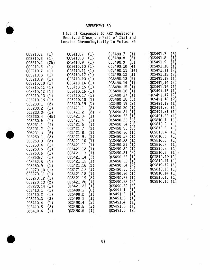
AMENDMENT 69
List of Responses to NRC QuestionsReceived Since the Fall of 1981 and
Located Chronologically in Volume 25
QCS210.1QCS210.3QCS210.4QCS210.5QCS210.7QCS210.8QCS210.9QCS210.10QCS210. 11QCS210.12QCS210.13QCS210.14QCS230.1QCS230.2QCS230.3QCS230.4QCS230.5QCS231.1QCS231.2QCS231.3QCS250.1QCS250.3QCS250.4QCS250.5QCS25o.6QCS250.7QCS250.8QCS25o.9QCS270.10QCS27o.11QCS27o.12QCS27o.13QCS27o.14QCS41o.1QCS41o.2QCS410.3QCS41o.4QCS41o.5QCS41o.6
(1)(1)(25)(1)(1)(1)(1)(1)(1)(1)(1)(1)(2)(1)(1)(48)(1)(1)(1)(5*).(2)(2)(I).(1)(1).(.1)(1)(1)
(1)(2)(1)(1)(.1)(3)(1)(3)(1)
QCS410.7QCS410.8QCS410.9
QCS410,.10QCS410.11QCS410.12QCS410.13QCS410.14QCS410.15QCS410.16QCS410.17QCS410.18QCS410.19QCS421.1QCS421.2QCS421.33QCS421..4QCS421.5QCS421.7QCS421.8ý:QCS421.9QCS421.10QCS421.11QCS421.12QCS421.13QCS421.14QCS421.15QCS421.16QCS421,17QCS421.18QCS421.19QCS421.20QCS421.23QCS490.1QCS490.2QCS490.3QCS490.4.QCS490.5QCS490.6
(1)
(2)
(2)(1)(1)(1)(1)(1)(1)(1)(2)(1)
(2)(2)(1)(3)(1)(3)(3)(1)(1.)(1)(1)(1)(31)(1)(2)(1)(1)(2)(1)(1)
(2)(.2)_(.1)
.QCS490.7QCS490.8QCS490.9QCS490.10QCS490.11QCS490.12QCS490.13QCS490.14QCS490.15QCS490.16QCS490.17QCS490.18QCS490.19QCS490 -20QCS490.21QCS490.22QCS490.23QCS490.24QCS490.25QCS490.26QCS490;27QCS490.28QCS490.29QCS490.30QCS490.31QCS490.32QCS490.33QCS490.34QCS490.35
.QCS490.36QCS490.37QCS490..38QCS490.39QCS491.1QCS491.2QCS491.3QCS491.4QCS491.5QCS491.6
(1)(2)(2)(4)(14)(1)(5)(1)(1)(2)(1)(3)(2)(1)(1)(1)(3)
~(3)
(1)(2)(1)
.(1)(2)(5)(1)(1)(5)(2)(1)(1)(1)
(1)(.1)(2)
QCS491.7QCS491.8QCS491.9QCS491.10QCS491.11QCS491.12QCS491..13QCS491.14QCS491.15QCS491.16QCS491.17QCS491.18QCS491. 19QCS4.91. 20QCS491.21QCS491.22QCS810. 1QCS810. 2QCS810.3QCS810. 4QCS810.5QCS810. 6QCS810. 7QCS8110.8QCS810. 9QCS810.10QCS810. 11QCS810.12QCS810.13QCS810.14QCS8!0.15QCS810.16
(3)(1)(1)(1)(2)(2)(1)(2)(1)(1)(2)(2)
(1)(1)
(1)
(1)(1).(1)(1)(1).(1).(1)(1)(1)(1)
Qi

AMENDMENT 70
List of Responses to NRC QuestionsReceived Since the Fall of 1981 and
Located Chronologically in Volume 25
QCS220.1QCS220.2QCS220.3QCS220.4QCS220.5QCS220.6QCS220.7.QCS220.8QCS220.9QCS220.10QCS220.11QCS220.12QCS220.13QCS220.14QCS220.15QCS220.16QCS220.17QCS220.18QCS220.19QCS220.20QCS220.21QCS220.22QCS220.23
QCS220.24QCS220.25QCS220.26QCS220.27QCS220.28QCS220.29QCS220.30QCS220.31QCS220.32QCS220.33QCS220.34QCS220.35QCS220.36QCS220.37QCS220.38QCS220.39QCS220.40QCS220.41QCS220.42QCS220.43QCS220.44QCS220.45
Qi

AMENDMENT 71
List of Responses to NRC QuestionsReceived Since the Fall of 1981 and
Located Chronologically in Volume 25 and 26
QCS231.1QCS421.6QCS421.21QCS421.24QCS421.25QCS421.26QCS421.28QCS421.29QCS421.32QCS421.33QCS421.35QCS421.36QCS421.38QCS421.39QCS421.40QCS421.41QCS421.43QCS421.44QCS421.45QCS421.46QCS421.49QCS421.50QCS421.51QCS421.52QCS421.53QCS421.54QCS421.55QCS421.56QCS421.57QCS421.59QCS491.5QCS760.6QCS760.7QCS760.8QCS760.9QCS76O.10QCS760.11QCS760.12QCS760.13QCS760.14QCS760.15QCS760.16QCS760.17QCS760.18QCS760.19QCS760.20QCS760.21QCS760.22
QCS760.23QCS760.24QCS760.25QCS760.26QCS760.27QCS760.29QCS760.31QCS760.32QCS760.33QCS760.34QCS760.35QCS760.37QCS760.38QCS760.39QCS760.40QCS760.41QCS760.42QCS760.43QCS760.44QCS760.45QCS760.46QCS760.47QCS760.48QCS760.49QCS760.50QCS760.51QCS760.52QCS760.53QCS760.54QCS760.55QCS760.56QCS760.57QCS760.58QCS760.59QCS760.60QCS760.61QCS760.62QCS760.63QCS760.64QCS760.65QCS760.66QCS760.67QCS760.68QCS760.69QCS760.70QCS760.71QCS760.72QCS760.73
QCS760.74QCS760.75QCS760.76QCS760.77QCS760.78QCS760.79QCS760.80QCS760.81QCS760.82QCS760.83QCS760.84QCS760.85QCS760.86QCS760.87QCS760.88QCS760.89QCS760.90QCS760,91QCS760.92QCS760,93QCS760,94QCS760,95QCS760,96QCS760.97QCS760.98QCS760.99QCS760.100QCS760,101QCS760,102QCS760,103QCS760.104QCS760,106QCS760.107
.QCS760,108QCS760.109QCS760.111QCS760,112QCS7.60,113QCS760,114Qs760,115QCS760 117QCS760,118QCS760.119QCS760.120QCS760,121QCS760.122QCS760.123QCS760.124
QCS760.125QCS760.126QCS760.127QCS760.128QCS760.129QCS760.130QCS760.132QCS760.133QCS760,134QCS760,135QCS760.136QCS760.137QCS760.138QCS760.139QCS760.140QCS760.141QCS760.142QCS760.143QCS760.144QCS760.145QCS760 146QCS760 147QCS760 148QCS760 149QCS760 150QCS760 151QCS760.152QCS760.153QCS760,154QCS760.155QCS760.156QCS760,157QCS760.158QCS760,159QCS760.160QCS760.161QCS760,162QCS760.163QCS760,164QCS760.165QCS760.167QCS760.168QCS760.169QCS760.170QCS760.171QCS760.173QCS760.174QCS760.179
Qi

AMENDMENT 71
QUESTION/RESPONSE SUPPLEMENT
This Question/Response Supplement contains an Amendment 71 tabsheet to be inserted following Qi page Amendment 70, August 1982. Page QiAmendment 71 is to be inserted following the Amendment 71 tab sheet.
This Amendment 71 provides both OLD and NEW Question/Responsepages which are to be inserted in numerical order behind the appropriatenumbered tabs in the PSAR. The parenthesis beside each Question/Responseshown indicates the number of pages associated with each Question/Response.
The following Question/Response pages are revised pages to OLDQUESTIONS and should be inserted in the appropriate PSAR Volumes otherthan Volumes 25 and 26.
REPLACEMENT PAGES
REMOVE THESE PAGES INSERT THESE PAGES
Q222.76-1, 2 Q222.76-1, 2Q241.83-1 Q241.83-1
With the issue of this PSAR Amendment 71, an additional PSARBinder (Volume 26) is being provided. In order to accommodate the volumeof Question/Response pages being issued with this amendment and the expectedvolume of Question/Response pages to be issued with future amendments, ashifting of pages from PSAR Volume 25 to Volume 26 is suggested. Thiscould be accomplished as follows:
a) Remove from PSAR Volume 25 numbered tabs 490, 491, 760, 810 and allpages behind each of these tabs and insert them into the new PSARVolume 26.
b) Question/Response pages provided with this Amendment for NRC QuestionsReceived Since the Fall of 1981 will be inserted behind the appropriatenumbered tabs in numerical sequence either in PSAR Volume 25 or 26 asappropriate. Additionally, new numbered tab 721 provided with thisAmendment will be inserted following page QCS491.22-1.
D

The following Question/Response pages are toorder in the PSAR Volumes 25 or 26 as appropriate.
be inserted in numerical
*QCS231.1,QCS421.6QCS421.21QCS421.24QCS421.25QCS421.26QCS421.28QCS421.29QCS421.32QCS421.33QCS421.35QCS421.36QCS421.38QCS421.39QCS421.40QCS421.41QCS421.43QCS421.44QCS421.45QCS421.46QCS421.49QCS421.50QCS421.51QCS421.52QCS421.53QCS421.54QCS421.55QCS421.56QCS421.57QCS421.59*QCS491.5QCS760.6QCS760.7QCS760.8QCS760.9QCS760.10QCS760.11QCS760.12QCS760.13QCS760.14QCS760.15QCS760.16QCS760.17QCS760.18QCS760.19QCS760.20QCS760.21QCS760.22
(1)(1)(1)(1)(1)(1)(1)(1)(1)(1)(1)(1).(1)(1)(1)(1)(1)(1)(1)(4).(1)
(2)(1)(1)(1)(2)(1)(2)(9)(1)
(54)(1)(1)(1)
(99)(1)(1)(1)(2)(1)(1)(1)(1)(1)(1)(1)(1)
QCS760.23QCS760.24QCS760.25QCS760.26QCS760.27QCS760.29QCS760.31QCS760.32QCS760.33QCS760.34QCS760.35QCS760.37QCS760.38QCS760.39QCS760.40QCS760.41QCS760.42QCS760.43QCS760.44QCS760.45QCS760.46QCS760.47QCS760.48QCS760.49QCS760.50QCS760.51QCS760.52QCS760.53QCS760.54QCS760.55QCS760.56QCS760.57QCS760.58QCS760.59QCS760.60QCS760.61QCS760.62QCS760.63QCS760.64QCS760.65QCS760.66QCS760.67QCS760.68QCS760.69QCS760.70QCS760.71QCS760.72QCS760.73
(1)(6)(1)(1)(3)(7)
(2)(1)(1)(2)(1)(1)(1)(4)(2)(1)(1)(2)(1)(.1)(1)(1)(1)(1)(1)(1)(1)(1)(1)(1.)(1)(3)(1)(1)(1)(1)(1)(1)(1)(1)(1)(1)(1)(1)(1)(1)(1)(1)
QCS760.74QCS760.75QCS760.76QCS760.77QCS760.78QCS760.79QCS760.80QCS760.81QCS760.82QCS760.83QCS760.84QCS760.85QCS760.,86QCS760.87QCS760.88QCS760.89QCS760.90QCS760.91QCS760.92QCS760.93QCS760.94QCS760.95QCS760.96QCS760.97QCS760.98QCS760.99QCS760. 100QCS760. 101QCS760. 102QCS760. 103QCS760.104QCS760. 106QCS760. 107QCS760.108QCS760. 109QCS760.111QCS760.112QCS760.113QCS760.114QCS760.115QCS760.117QCS760.118QCS760119QCS760.120QCS760.121QCS760.122QCS760.123QCS760.124
(2)(1)(1)(2)(1)
(3)(1)(1)(1)(2)(1)(1)(3)(1)(1)(1)(2)(1)(2)(1)(1)(1)(2)(1)(1)(3)(1)(1)(2)(1)(1)(2)(1)(1)(1)(1)(1)(1)(1)(I)(2)(1)(1)(1)(2)(1)(1)(1)
QCS760.125QCS760.126QCS760.127QCS760.128QCS760.129QCS760.130QCS760.132QCS760.133QCS760.134QCS760.135QCS760.136QCS760.137QCS760.138QCS760.139QCS760.140QCS760.141QCS760.142QCS760.143QCS760.144QCS760.145QCS760.146QCS760.147QCS760.148QCS760.149QCS760.150QCS760.151QCS760.152QCS760.153QCS760.154QCS760.155QCS760.156QCS760.157QCS760.158QCS760.159QCS760.160QCS760.161QCS760. 162QCS760.163QCS760.164QCS760.165QCS760.167QCS760.168QCS760.169QCS760.170QCS760.171QCS760.173QCS760.174QCS760.179
(2)(2)(1)(1)(1)(2)(1)(1)(1)(1)(1)(4)(1)(1)(1)(2)(1)(1)(1)(1)*(1)(1)(1)(1)(1)(1)(1)(1)(1)(1)(1)(2)(1)(1)(2)(1)(1)(1)(1)(1).(2)(1)(1)(1)(2)(1)(2)(2)
*These are replacement pages.
E

AMENDMENT 72
List of Responses to NRC QuestionsReceived Since the Fall of 1981 and
Located Chronologically in PSAR Volumes 25 and 26
QCS220.25QCS421.9QCS421.17QCS421.22QCS421.27QCS421.30QCS421.31QCS421.34QCS421.36QCS421.37QCS421,.42QCS421.47QCS421.48QCS421.58-QCS721.1
QCS760,13.QCS760.28QCS760.30QCS760.36QCS760.105QCS760,110QCS760,116QCS760-131QCS760.166QCS760.172QCS760.175QCS760.176QCS760.177QCS760,178
Qi

AMENDMENT 73
LIST OF RESPONSES TO NRC QUESTIONS
There are no new NRC Questions in Amendment 73.
Q-i

AMENDNENT 74
LIST OF RESPONSES TO NRC QUESTIONS
RECEIVED SINCE THE FALL OF 1981
QCS421.26QCS421.45QCS430.1QCS430.2QCS430.3QCS430.5QCS430.6QCS430.7QCS430.8QCS430.9QCS430.10QCS430.11QCS430.12QCS430.13QCS430.14QCS430.15QCS430.16QCS430.17QCS430.18QCS430.19QCS430.20QCS430.21QCS430.22QCS430.23QCS430.24QCS430.25QCS430.26QCS430.27QCS430.28QCS430.29QCS430.30QCS430.31QCS430.32QCS430.33QCS430.34QCS430.35
QCS430.36QCS430.37QCS430.38QCS430.39QCS430.40QCS430.41QCS430.42QCS430.43QCS430.44QCS430.45QCS430.46QCS430.47QCS430.48QCS430.49QCS430.50QCS430.51QCS430.52QCS430.53QCS430.54QCS430.55QCS430.56QCS430.57QCS430.58QCS430.59QCS430.60QCS430.61QCS430.62QCS430.63QCS430.64QCS430.65QCS430.66QCS430.67QCS430.68QCS430.69QCS430.70QCS430.71
QCS430.72QCS430.73QCS430.74QCS430.75QCS430.76QCS430.77QCS430.78QCS430.79QCS430.80QCS430.81QCS430.82QCS430.83QCS430.84QCS430.85QCS430.86QCS430.87QCS430.88QCS430.89QCS430.90QCS430.91QCS430.92QCS430.93QCS430.94QCS430.95QCS430.96QCS430.97QCS430.98QCS430.99QCS430.100QCS430.101QC5430,102QCS430.103QCS430.104QCS760.144
Qi

Department of Energy
Wshinaton.f. 20545Docket NO' 20-535
HQ:S:83:l97
February 8, 1983
Mr. Paul S. Check, DirectorCRBR Program OfficeOffice of Nuclear Reactor RegulationU.S. Nuclear Regulatory CommissionWashington, D.C. 20555
Dear Mr. Check:
AMENDMENT 75 TO THE PRELIMINARY SAFETY ANALYSIS REPORT (PSAR) FOR CLINCH RIVERBREEDER REACTOR PLANT (CRBRP)
The application for a Construction Permit and Class 104(b) Operating Licensefor the CRBRP, docketed April 10, 1975, in NRC Docket No. 50-537, is herebyamended by the submission of Amendment 75 to the PSAR pursuant to 50.34(a) of10 CFR, Part 50.
This Amendment 75 includes: Revisions to Section 1.4, "Identification ofProject Participants;" Section 5.0, "Heat Transport and Connected Systems;"Section 5.7, "Overall Heat Transport System Evaluation;" Chapter 7,"Instrumentation and Controls;" Chapter 9, "Auxiliary Systems;" Section 17D,"A Description of the Westinghouse Quality Assurance Program;" and otherupdates and revisions.
A Certificate of Service, confirming service of Amendment 75 to the PSAR upondesignated local public officials and representatives of the EnvironmentalProtection Agency, will be filed with your office after service has been made.Three'signed originals of this letter and 97 copies of this amendment, eachwith a copy of the submittal letter, are hereby submitted.
y ,Sincerely,
JAn R. Longene4kerActing Director, Office of
Breeder Demonstration Projects,X Office of Nuclear Energy
'I SUBSCRIBED AND SWORN to before meEnclosure / this A>• day of January 1983
cc: Service ListStandard Distribution I
Licensing Distribution • V . , ,
/ ~**r.~i,. /6~

SERVICE LIST
Atomic Safety & Licensing BoardU. S. Nuclear Regulatory CommissionWashington, D. C. 20555
Atomic Safety & Licensing Board PanelU. S. Nuclear Regulatory CommissionWashington, D. C. 20555
Mr. Gerald LargenOffice of the County ExecutiveRoane County CourthouseKingston, TN 37763
Dr. Thomas CochranNatural Resources Defense Council, Inc.1725 I Street, NWSuite 600Washington, DC 20006
Docketing & Service StationOffice of the SecretaryU. S. Nuclear Regulatory CommissionWashington, DC 20555
Counsel for NRC StaffU. S. Nuclear Regulatory CommissionWashington, DC 20555
William B. Hubbard, Esq.Assistant Attorney GeneralState of TennesseeOffice of the Attorney General422 Supreme Court BuildingNashville, TN 37219
Mr. Gustave A. LinenbergerAtomic Safety & Licensing BoardU. S. Nuclear Regulatory CommissionWashington, DC 20555
Marshall E. Miller, Esq.ChairmanAtomic Safety & Licensing BoardU. S. Nuclear Regulatory CommissionWashington, DC 20555
William E. Lantrip, Esq.Attorney for the City of Oak Ridge725 Main Street, EastOak Ridge, TN 37830
Dr. Cadet H. Hand, Jr., DirectorBodega Marine LaboratoryUniversity of CaliforniaP. 0. Box 247Bodega Bay, CA 94923
Lewis E. Wallace, Esq.Division of LawTennessee Valley AuthorityKnoxville, TN 37902
2/17/82

STANDARD DISTRIBUTION
Mr. R. J. Beeley (2)Program Manager, CRBRPAtomics International DivisionRockwell InternationalP. 0. Box 309Canoga Park, CA 91304
Mr. Michael C. Ascher (2)Project Manager, CRBRPBurns and Roe, Inc.700 Kinderkamack RoadOradell, NJ 07649
Mr. Percy Brewington, Jr. (2)Acting DirectorClinch River Breeder Reactor PlantP. 0. Box UOak Ridge, TN 37830
Mr. Dean Armstrong (2)Acting Project Manager, CRBRPStone & Webster Engineering Corp.P. 0. Box 811Oak Ridge, TN 37830
Mr. William J. Purcell (2)Project Manager, CRBRPWestinghouse Electric CorporationAdvanced Reactors DivisionP. 0. Box W.Oak Ridge, TN 37830
Number of copies in parentheses.
Mr. W. W. Dewald, Project Manager (2)CRBRP Reactor PlantWestinghouse Electric CorporationAdvanced Reactors DivisionP. 0. Box 158Madison, PA 15663
Mr. H. R. Lane (1)Resident Manager, CRBRPBurns and Roe, Inc.P. 0. Box TOak Ridge, TN 37830
Mr. George G. Glenn, Manager (2)Clinch River ProjectGeneral Electric CompanyP. 0. Box 508Sunnyvale, CA 94086
1/11/82

LICENSING DISTRIBUTION
Mr. Hugh ParrisManager of PowerTennessee Valley Authority500A CST 2Chattanooga, TN 37401
Dr. Jeffrey H. Broido, ManagerAnalysis and Safety DepartmentGas Cooled Fast Reactor ProgramGeneral Atomics CompanyP. 0. Box 81608San Diego, CA 92138
Mr. George EdgarMorgan, Lewis, and Bockius1800 M StreetSuite 700Washington, DC 20036
2/17/82

PAGE REPLACEMENT GUIDE FOR
AMENDMENT 75
CLINCH RIVER BREEDER REACTOR PLANT
PRELIMINARY SAFETY ANALYSIS REPORT
(DOCKET NO. 50-537)
Transmitted herein is Amendment 75 to Clinch River BreederReactor Plant Preliminary Safety Analysis Report, Docket 50-537. Amendment75 consists of new and replacement pages for the PSAR text and Responsesto NRC Questions.
Vertical margin lines on the right hand side of the page areused to identify changes resulting from NRC Questions and margin lineson the left hand side are used to identify new or changed design information.
The following attached sheets list Amendment 75 pages andinstructions for their incorporation into the Preliminary Safety AnalysisReport.
8302090334 830208PDR ADOCK 05000537B PDR

AMENDMENT 75
LIST OF RESPONSES TO NRC QUESTIONS
There are no new NRC Questions in Amendment 75.
Qi

I"?Department of EnergyWashington D.C. 20545
Docket. No. 56-537HQ:S:83:223
March 2, 1983
Dr. J. Nelson Grace, DirectorCRBR Program OfficeOffice of Nuclear Reactor RegulationU.S. Nuclear Regulatory CommissionWashington, D.C. 20555
Dear Dr. Grace:
AMENDMENT 76 TO THE PRELIMINARY SAFETY ANALYSIS REPORT (PSAR) FOR CLINCHRIVER BREEDER REACTOR PLANT (CRBRP)
The application for a Construction Permit and Class 104(b) Operating Licensefor the CRBRP, docketed April 10, 1975, in NRC Docket No. 50-537, is herebyamended by the submission of Amendment 76 to the PSAR pursuant to 50.34(a)of 10 CFR, Part 50.
This Amendment 76 includes: Revisions to Section 3.1, "Conformance withGeneral Design. Criteria;" Section 4.2, "Reactor Mechanical Design;" Chapter"Instrumentation and Controls;" Chapter 9, "Auxiliary Systems;" Appendix A,"Computer Codes;" and other updates and revisions.
7,
A Certificate of Service, confirming service of Amendment 76 to the PSAR upondesignated local public officials and representatives of the EnvironmentalProtection Agency, will be filed with your office after service has been made.Three signed originals of this letter and 97 copies of this amendment, eachwith a copy of the submittal letter, are hereby submitted.
Sncerely,
Jo R. Logen~e
Acting Director, Office ofBreeder Demonstration Projects
Office of Nuclear Energy
Enclosure
cc: Service ListStandard DistributionLicensing Distribution
SUBSCRIBED AND SWORN to before methis Z' day of February 1983

SERVICE LIST
Atomic Safety & Licensing BoardU. S. Nuclear Regulatory CommissionWashington, D. C. 20555
Atomic Safety & Licensing Board PanelU. S. Nuclear Regulatory CommissionWashington, D. C. 20555
Mr. Gerald LargenOffice of the County ExecutiveRoane County CourthouseKingston, TN 37763
Dr. Thomas CochranNatural Resources Defense Council, Inc.1725 1 Street, NWSuite 600Washington, DC 20006
Docketing & Service StationOffice of the SecretaryU. S. Nuclear Regulatory CommissionWashington, DC 20555
Counsel for NRC StaffU. S. Nuclear Regulatory CommissionWashington, DC 20555
William B. Hubbard, Esq.Assistant Attorney GeneralState of TennesseeOffice of the Attorney General422 Supreme Court BuildingNashville, TN 37219
Mr. Gustave A. LinenbergerAtomic Safety & Licensing BoardU. S. Nuclear Regulatory CommissionWashington, DC 20555
Marshall E. Miller, Esq.ChairmanAtomic Safety & Licensing BoardU. S. Nuclear Regulatory CommissionWashington, DC 20555
Dr. Cadet H. Hand, Jr., DirectorBodega Marine Laboratory.University of CaliforniaP. 0. Box 247Bodega Bay, CA 94923
Lewis E. Wallace, Esq.Division of LawTennessee Valley AuthorityKnoxville, TN 37902
William E. Lantrip, Esq.Attorney for the City of725 Main Street, EastOak Ridge, TN 37830
Oak Ridge
2/17/82

STANDARD DISTRIBUTION
Mr. R. J. Beeley (2)Program Manager, CRBRPAtomics International DivisionRockwell InternationalP. 0. Box 309Canoga Park., CA 91304
Mr. Michael C. Ascher (2)Project Manager, CRBRPBurns and Roe, Inc.700 Kinderkamack RoadOradell, NJ 07649
Mr. Percy Brewington, Jr. (2)Acting DirectorClinch River Breeder Reactor PlantP. 0. Box UOak Ridge, TN 37830
Mr. Dean Armstrong (2)Acting Project Manager, CRBRPStone A Webster Engineering Corp.P. 0. Box 811Oak Ridge, TN 37830
Mr. William J. Purcell (2)Project Manager, CRBRPWestinghouse Electric CorporationAdvanced Reactors DivisionP. 0. Box W;Oak Ridge, TN 37830
Number of copies in parentheses.
Mr. W. W. Dewald, Project Manager (2)CRBRP Reactor PlantWestinghouse Electric CorporationAdvanced Reactors DivisionP. 0. Box 158Madison, PA 15663
Mr. H. R. Lane (1)Resident Manager, CRBRPBurns and Roe, Inc.P. 0. Box TOak Ridge, TN 37830
Mr. George G. Glenn, Manager (2)Clinch River ProjectGeneral Electric CompanyP. 0. Box 508Sunnyvale, CA 94086
01/11/82

LICENSING DISTRIBUTION
Mr. Hugh ParrisManager of PowerTennessee Valley Authority500A CST 2Chattanooga, TN 37401
Dr. Jeffrey H. Broido, ManagerAnalysis and Safety DepartmentGas Cooled Fast Reactor ProgramGeneral Atomics CompanyP. 0. Box 81608San Diego, CA 92138
Mr. George EdgarMorgan, Lewis, and Bockius1800 M StreetSuite 700Washington, DC 20036
2/17/82

AMENDMENT 76
LIST OF RESPONSE TO NRC QUESTIONS
REFERENCE NRC LETTER DATED DECEMBER 1, 1976
NRC
QUESTION NO..
110.78
Amend. 76March 1983

AMENDMENT 77
LIST OF RESPONSES TO NRC QUESTIONS
There are no new NRC Questions in Amendment 77.
Qi

Question 001.1 (1.1.2.2)
You have established the goal that "The probability of exceeding 10 CFR100 guidelines shall be less than one. chance in one million per reactoryear.." Later in setting up reliability allocations (Section C.l ofAppendix C) you become quite rigorous in apportioning the goal of 1l- 6 /yrby subdividing it into:
Element Goal
Shutdown System Failure l0-7
Shutdown Heat 8 x l0-7
Removal Failure
Other Faults l0-7
Leading to Lossof Coolable Geometry
The assignment of 80% of the goal to a single element, shutdown heatremoval, raises several questions.
a. Can one make a meaningful distinction between 8 x lO-7 and 1 x 10⁻⁶?b. Should the bulk of the goal be allocated to a single failure
mechanism?c. Is the design approach for shutdown heat removal such that there
is practical limit to the goal that can be attained? For example,does the need for AC power to transfer heat to the steam systemconstitute such a limitation?
d. Two of the elements in this tripartite allocation are singularelements, the shutdown system failure and the shutdown heatremoval failure. The third element is a sum of all others.Does this imply that the individual elements in this sum areallocated a probability substantially less than the 10-7/yrallocated to the sum? For example, would you allocate a pro-bability of the order of 10- 8 /yr to an event in the sum suchas a serious airplane crash?
Present your responses to these questions.
Response:
The information requested is in revised Section C.1.3.3. 125
QO01.1-1 Amend. 25
Aug. 1976

Question 001 .2
Is Appendix D considered part of the Reference Design Submittal?
Response:
With the deletion of Appendix D in Amendment 24 this question is nolonger applicable.
QOOl.2-1
Amend., 62Nov. 1981

Question 001.3 .(Table 1.1-1)
Table 1.1-3 is referred to, this table is missing.
Response:
Table 1.1-3, List of Extremely Unlikely Faults Used as Design Bases,was included in the 100 copies of the PSAR transmitted to NRC by PMCletter TS-75-242 dated June 13, 1975.
Amend. 1Q 001 .3-1 -July, 1975

Question 001.4 (Table 1.1-2)
Discuss the bases for the assigned levels and ranges given for theoccurrence probabilities of the various events and accidents.
Response:
A revised Table 1.1-2 is provided. Engineering judgement was usedto group the various design basis events and predict the numericalvalues associated with the groups previously indicated in the Table.
QOOl.4-1
Amend. 15April 1971

Question 001.5 (1.2-38),
Provide elevation views of the Control Building and the DieselGenerator Building.
Response
These elevation views are provided on new Figure 1.2-44, Control BuildingSection A-A and Section B-B, and new Figure 1.2-46, Diesel GeneratorBuilding, Section A-A and Section B-B.
Q 001.5-1Amend.l 1July, 1975

Question 6
Provide a description of pertinent experimental data, analytical modelsand plans for obtaining future data regarding fuel rod-wire wrap inter-actions.
Response:
This information requested has been provided under separate cover.
Q6-1 Amend. 26Aug. 1976.

Question 001.7 (3.1.2)
Provide a complete list of all components or parts of componentswhich comprise the reactor coolant boundary.
Response:
The list of Components or Parts of Components which comprise theReactor Coolant Boundary can be found in new Table 3.1-1.
125
QOO .7-1
Amend. 25Aug. 1976

Question 001.8 (3.1.2)
For Systems whose failure-could not result in fuel designlimits being exceeded, justify the proposed identificationof nozzles as the outermost part of a component or its associatedpiping which comprises a part of the reactor coolant boundary.
Response:
The justification for identifying the nozzles connecting thesystem to the primary heat transport system as being the reactorcoolant boundary for those systems whose failure could not result inthe fuel design limits is as follows:
The only systems which fall into this category are the Argon cover gaspressurization and equalization systems and the primary sodiummakeup and overflow systems. These low pressure systems areconnected to the primary cooling system and are located in inerted innercells. Failure of these systems would only result in minor consequences,such as limited sodium spill effects or release of reactor cover gas.
On the basis described above, it is therefore justifiable that, forthese particular small branch lines, the connecting nozzle beconsidered as the end of the reactor coolant boundary.
QOOl. 8-1 Amend. 1July 1975

Question 001.9 (3.1.2)
Provide a complete list of all components or parts of componentswhich comprise the intermediate coolant boundary.
Response:
Components which comprise the intermediate coolant boundary are listedin new Table 3.1-2. 25
Q001. 9-1 Amend. 25Aug. 1976

Question 9
Provide a discussion of the methods used for the analysis of fuelbundle response to a seismic event including the forcing functionsand pertinent bundle properties. Applicable experimental datashould be presented and discussed; derivations of all equationsshould be given or appropriately referenced.
Response:
The information requested has been provided under separate coverin the topical report, WARD-D-0158, "Seismic Evaluation Methodsand Criteria for CRBRP Fuel Assembly Duct Structure."
Q9-1 Amend. 37March 1977

Question 001.10 (3.1.2)
Identify any systems, components or parts of components connected to theintermediate coolant system, not penetrating reactor containment, whosefailure would impair the capability of the intermediate coolant system toperform its safety function.
Response:
Revised Section 3.1.2 identifies esstential portions of the intermediatecoolant boundary.
Q001.10-1 Amend. 16Apr. 1976

Question 001.11'.(32.•2)
For systems and components whose failure could not impair thecapability of the intermediate coolant system to perform its safetyfunction, justify the proposed identification of nozzles as theoutermost part of a component or its associated piping which comprisespart of the intermediate coolant boundary.
Res ponse •
The justification for identifying the nozzles connecting thesystem to the intermediate heat transport system as being the inter-mediate coolant boundary for those systems whose failure could notimpair the capability of the intermediate coolant system to performits safety function is as follows:
The only systems which fall into this category are the cover gaspressurization and equalization system and the sodium fill anddrain system. Failure of these low pressure systems would onlyresult in minor consequences such as loss of cover gas and minorsodium spills. While such spills could lead to sodium fires,the safety function of the IHTS (viz: to remove heat) is notimpared. The consequences of a large sodium spill are presentedin Chapter 15 (Section 15.6.1.5) wherein it is indicated that evenfor a large spill there would be no propagation of the event andthus no loss of safety function. On the basis described above,it is therefore justifiable that for these particular smallbranch lines, the connecting nozzle may be considered as the endof the intermediate coolant boundary.
QOOl.ll-1 Amend. 1July 1975

Question 001.12 (3.1.2)
Confirm that anticipated operational occurrences in the definitionof Fuel Design Limits means all those events identified as AnticipatedFaults in the definition of off-normal conditions.
Response:
In the definition of Fuel Design Limits, "anticipated operationaloccurrences" was meant to imply that those events identified asOff-Normal Conditions, namely: both Anticipated Faults and Unlikely FaultsFaults (see response to Question 001.13 and also Table 15.1.2-3 ofthe PSAR).
In conjunction with this response, the definition of Fuel DesignLimits in Section 3.1.2 is revised to read:
"Fuel Design Limits. Fuel design limits means those limitssuch as temperature, burnup, fluence, and cladding strain whichare specified by the designer for normal operation and off-normalconditions."
QOOl .12-1 Amend. 1July 1975

Question 001.13 (3.1.2)
The text of this section should compare your definitions of NormalOperation, Off-Normal Conditions, and Extremely Unlikely.Faults tothe spectrum of operational conditions and events used in 10 CFR50 Appendix A.
Response:
This comparison can be found in new Section 3.1.2.1 and new Table3.1-3.
QO01.13-1
1 25
Amend. 25Aug. 1976

Question 001.14 (3.1.3.3)
The response to Criterion 23 does not indicate the means by. whichcomponents are protected from fallout of sodium vapor or reactionproducts. Provide a description of the means to do so.
Response:
The information requested is incorporated in the changed PSARpage 3.1-21.
QOOl .14-1 Amend. 1July 1975

Question 001.15 (3.1.3.4)
Justify the omission of a mandatory leak identification requirementin Criterion 32.
Response:
For CRBRP, detection and confirmation of a leak in the primary systemleads to shutdown of the plant regardless of the precise locationtherefore, location of the leak is an economic consideration and amandatory requirement in the Criterion is not warranted.
QOOl. 15-1 Amend. 3Aug. 1975

Question 001.16 (3.1.3.4)
Justify the omission of a mandatory leak identification requirement inCriterion 36.
Response:
The CRBRP Criterion 36 is the same criterion, verbatim, as set forth inthe "Interim General Design Criteria for the Clinch River Breeder ReactorNuclear Power Plant," issued by the Commission on July 19, 1974. Thecriterion number in the Commission's Interim GDC is Criterion 34.
Through the discussions during a series of pre-application meetings withthe Commission, the applicant agreed to use the Commission's Criterionverbatim as specified.
QOO1 .16-1 Amend. 2August 1975

Question 001.17 (3.1.3.5)
Confirm that Criterion 52 applies to all structures where a specifiedleak rate must be demonstrated.
Response:
The information requested is in revised Section 3.1.3.5. 1 25
QO01 .17-1
Amend. 25Aug. 1976

-Question 001.18 (3.1.3.5)
Justify the basis for the statement that "the design of the IHTSlines meet the requirements of GDC 57".
Response:
The system boundary of the IHTS main lines is classified as ASME-IIICode Class 2. It will be protected against accidents, extreme environ-mental conditions and natural phenomena by a Seismic Category Istructure. Therefore, the design of these lines meets the require-ments of GDC 57 set forth in Section 3.1.3 of this PSAR.
QOOl. 18-1 Amend. 1July, 1975

Question 001.19 (3.1.3.6)
Provide the general criteria to be applied to assure that systemswhich handle or contain irradiated fuel shall be designed, fabricated,installed, and tested to the highest quality standards practical.
Response:
The systems which handle or contain irradiated fuel assemblies willconform specifically to the following CRBRP General Design Criteria:61, 62 and 63 which are essentially identical to the related criteriain 10 CFR 50. Revised Section 3.1.3.6 includes this information.
In addition, GDC 1, 2, 3, 3a and 4 will also apply, as appropriate, tothese systems.
Quality standards for these systems are determined in accordance withthe procedures provided in Section 3.2, which is consistent with thebasic intent of Regulatory Guide 1.26.
25
QO01 .19-1 Amend. 25Aug. 1976

Question 001.20 (3A.1.1)
The inner cell system is intended to mitigate the consequences of sodiumspills, to preclude detrimental sodium/material reaction, and to maintainstructural integrity following any of the design basis accidents. Explainyour claim then that "the inner cell system of the CRBRP is not an Engi- 127neered Safety Feature". In particular, explain what design or qualitydifferences in the system derive from your choice and exclude it from thelist of Engineered Safety Features.
Response:
The inner cell system is designed to have a nominal leak tightness for thepurpose of maintaining th4 purity of the inerted atmosphere in the innercells during normal plant operation. The safety analyses, which show com-pliance with the 10 CFR 100 radiological guidelines for all the postulatedsodium spill accidents have not taken credit for any leak tightness of thein-containment cells.
The analysis of sodium spills assumes, however, that the cell liners preventsodium from contacting the concrete. This assumption does establish afunctional requirement for cell liners. It is expected that, even if theliner does fail and sodium does contact with concrete, the reaction is self-limiting. Cell liners are being designed to remain intact for the life ofthe plant for both normal operating and accident conditions. Fabricationand inspection requirements will insure that the as-built liner is installedas specified in the design.
Development programs are planned to provide additional assurance that thecell liner will remain intact during accident conditions. Tests are alsoplanned to show that even if there is large local liner failure underaccident conditions the sodium concrete reaction will be self limiting.A more detailed discussion of cell liner design criteria and developmentprograms is contained in the response to Q130.37.
Since the liners are a passive component of the inner cell system and arenot required to serve as a containment barrier against the accidental releaseof radioactivity, liners are not considered Engineering Safety Features.It will be shown that the inner cell system will function as required inthe event of a sodium spill. No credit will be taken in the safety analysesfor design features that cannot be proven to be functional by test and/oranalysis.
The single exception is the RAPS surge and delay tank cell, located in theReactor Service Building. This cell does not contain sodium or NaK. Thiscell will be considered as an Engineered Safety Feature due to leak tightnessrequirements. Design bases for this cell are as described in Section.3A.l.2of the PSAR.
Amend. 27
QOO1.20-1 Oct. 1976

Question 001.21 (3A.1.2)
This section does not provide the information requested in Section6.3.1.1 of the Standard Format. Revise it to provide thisinformation. In particular, note that none of the five items presentedin this section are responsive to the five items of 6.3.1.1 in theStandard Format.
Response:
For the Reference Design, as described in the CRBRP PSAR, the onlyinner cell specifically designed to act as a containment barrieragainst the accidental release of radioactivity is the RAPS Surge andDelay Tank Cell located in the Reactor Service Building. No creditfor retention, holdup, plate-out, or settling of accidentallyreleased radioactive material is taken for any other inner cell in theReference Design evaluations.
The five information items requested in Section 6.3.1.1 of the StandardFormat, for the RAPS Surge and Relay Tank Cell, are provided on newpages 3A.l-2a and 3A.l-2b.
QOOl. 21-1 Amend.. 1July 1975

Question 001.22 (3A.1.3)
Table 3A.1-3 does not provide a sufficient description of the inertcell system. Provide a design description of the system. Refer toSection 6.3.1.2 of the Standard Format for the scope and nature ofthe design information required. In particular, present simplesketches of the cells showing the principal equipment in each celland the extent of cell sealing required for piping and electricalpenetrations and access openings. Include a summary of your designcalculations which established the cell heat loads listed inTable 3A.l-l.
Response:
The information requested is provided in revised Section 3A.1.3 andTables 3A.l-1 and 3A.1-3.
Amend. 3Q001.22-1 Aug. 1975

Question 001.23 (3A.1.3)
Describe the design criteria to be used to establish the location of thetransition from "hot" cell liner design to "cold" dell liner design.Describe how you will account for spray and splash effects and in-cell heattransfer.
Response:
The current cell liner design concept is that of a fixed liner whichwill be used in all areas of lined cells (ie there will be no differentia-tion made between "hot' and "cold" liners). Therefore, there will be notransition point between "hot" cell liner design and "cold" cell liner design.PSAR Section 3.8.3.1 ane Appendix E Supplement Section 15.6.1.6.2 have beenrevised accordingly.
Sodium spray and splash effects and in-cell heat transfer are discussed inthe responses to questions 130.38 and 130.39.
24
Amend. 24July 1976QO01 .23-1

I
Question 001.24 (3A.1.4)
This section does not provide a sufficient design evaluation. Revisethis section to includethe information requested in Section 6.3.1.3 ofthe Standard Format. Include in the revised section more detaileddiscussion of system response following a sodium spill.
Response:
As stated in Section 3A.1.1 of the PSAR, the inner cells within thecontainment of the CRBRP are designed and required only to have anominal leaktightness for the purpose of maintaining the purity ofthe inerted atmosphere in these cells during normal plant operation.Note that the inerted cells are operated at a slight negative pressureto provide the desired normal operating leakage path. For theradiological safety analyses of all the related accidents such assodium spills, no credit is taken for any leaktightness or pressurecontrol of these cells. It is assumed that all airborne reactionproducts are released directly to the containment.
The analyses used to set structural design requirements are based onthe maximum pressure associated with the events used in the designbasis for the cells assuming no leakage.
Because of this selection of functional design, the inner cells of theCRBRP are not Engineered Safety Features. Consequently, the informationpresented in 3A.1.4 provides the bounding design evaluations for thesecell designs for both radiological and structural evaluations recognizingthat the cells are not engineered safety features.
Analysis with respect to the consequences of sodium spills is providedin Section 15.6 of the PSAR.
Further details relating to the question have been provided in the.response to Q.001.25, Amendment 1 to the PSAR.
Q001.24-I Amend. 3
Aug. 1975

Question 001.25 (3A.1.5)
Justify your conclusion that periodic testing of the cells is notrequired. Discuss your basis for continuing confidence in cellliner integrity throughout the life of the plant. Include in yourdiscussion the predictability of cell-to-cell leakage as well ascell-to-upper containment leakage.
Response:
The information requested is discussed in.revised Section 3A.1.5.
QOOl.25-1
125
Amend. 25Aug. 1976

Question 001.26 (3A.,.7)
Revise this section to provide a complete identification of the cellmaterials, especially those that would be exposed to spilled or spraysodium at high temperature.
Response:
Section 3A.,.7 has been revised in response to this question.31
QOOl .26-1Amend. 31Nov. 1976

Question 001.27.
Provide at least the preliminary values for the TBD items in Table3A.1-2.
Response:
The preliminary values for the TBD items have been included in theamended PSAR Table 3A.1-2.
QOOI .27-1 Amend. 1July 1975

Question 001.28 (3A.2.2)
Provide an analysis of the safety implications of loss of heatremoval for the Head Access Area.
Response:
The requested analysis is in revised Section 3A.2.2. I 25
QOOl .28-1 Amend. 25Aug. 1976

Question 001.29 (4.2.3.3.1.5)
(Section 4.2.3.3.1.5) As of 5/6/75, the only reference for B4 C ControlMaterial Data, i.e., HEDL-TME 75-19, had not been cleared for release byHERL. Provide the referenced document if it has not been made availablein the interim. (Ref. 44)
Response:
The referenced (Ref. 44) document, HEDL-TME 75-19, should currently beavailable in NRC' libraries. However, to assure a timely review ofSection 4.2.3.3.1 .5, the required document is being provided to NRCunder separate cover.
QOOI .29-1 Amend. 1July 1975

Question 001.30- (4.3.2.1)
Provide the secondary control rod clad OD and thickness even if suchvalues are preliminary and subject to change. The referenced tableindicated that these are under development.
Response:
Table 4.3-1 has been revised to provide the information requested.
QOOl.30-1 Amend. 2August 1975

Question 001.31 (4.3.2.1.5)
Justify your-proposed use of the Source Range Flux Monitoring System.In particular, provide the experimental and analytical basis for itsneutron-flux monitoring capability when the reactor is shutdown andfuel is stored in the in-vessel storage.
Response:
The response to this question has been incorporated into the PSAR asrevised section 4.3.2.1.5.
QOOl.31-1 Amend. 2August 1975

Question 001.32 (4.3.2.3.1)
Justify your omitting consideration of any plutonium(fissile) Doppler effect, as it affects the magnitude of theM/O Doppler reactivity and its temperature dependence. Providea more detailed description of the experimental validation ofthe CRBRP Doppler Coefficients. Are the SEFOR experimentsyour only data base?
Response:
The response to this question has been incorporated in the first andsixth paragraph of Section 4.3.2.3.1 and additional data over andabove the SEFOR data are also provided.
QOOl .32-1 Amend. IJuly 1975

Question 001.33 (4.3.2.7.1)
You comment that the major discrepancy between the ZPR criticals and theCRBRP is in the use of plates in a square lattice instead of cylindricalpins in an hexagonal array. Another discrepancy is that the criticalsoperate at room temperature. Provide a justification for not consideringthis effect of temperature when comparing ZPR reactivity measurements andcorresponding CRBRP analysis.
Response:
The response to this question has been incorporated into Section 4.3.2.7.1.
QOOl .33-1 Amend. 1July 1975

Question 001.34 (4.3.3.5)
It is not clear how Figure 4.3-40 provides information on theZPPR-3 experimental program. Provide clarifying information.
Response:
The response to this question is contained in revised Section 4.3.3.5and an amended version of Figure 4.3-40.
QO01 .34-1 Amend. 1July 1975

Question 001.35 (15.1.2)
The design limits for fuel pin integrity shown on page 15.1-75are "preliminary" and are referred to as conservative estimateswhich "..could change or perhaps even the method of evaluatingperformance could change." Provide further justificationfor the preliminary nature of these limits in light of theirimportance in assessing the margin of safety provided by thetransient performance capability of the fuel rod and the PPS.
Response:
The response to this question has been incorporated into therevised section 15.1.2.
Q 001.35 , 1 Amend 2August, 1975
K. Question 001.36 (15.1.2.1)
Justify the use of results from unirradiated tests (Table15.1.2-4) in demonstrating the failure predictive capabilityof the CDF procedure.
Response:
The response to this question has been incorporated into thePSAR by the addition of revised section titled, "ExperimentalVerification of the CDF Procedure," to follow a new sectiontitled, "Discussion or Mechanical Properties Used in theCDF Procedure." (See new PSAR Page 15.1-63).
( QOOl. 36-1 Amend. 2August 1975

Question 001.38 (15.2)
Provide a mechanistic description offuel-pin transientbehav-ior for.theseveral cases considered. In particular, descrhbe the primary and secondaryloading on the fuel pin cladding over the full range of burnups and power..ratings.
Response:
The requested description is provided in revised Section 15.1,2.1. 125
Q001.38-1 Amend. 25Aug. 1.976

Question 001.39 (D5.1.4.1)
Provide documentation whichproject physics groups haveon . . . sodium void worths.
supports the statement: "Knowledgeablecurrently placed a +50% uncertainty" (Pg D5-6, 7) -
Response:
This question requests clarification of information which is no longerapart of the current documentation. The Project has since consolidated
all considerations given Hypothetical Core Disruptive Accidents intoreport CRBRP-3 (References lOa and lOb, PSAR Section 1.6) and its asso-ciated references; consequently, PSAR Appendices D and F have beenwithdrawn in Amendments 24 and 60'respectively. A discussion of sodiumvoid worth uncertainty is provided in PSAR Section 4.3.2.3.2 and Section6 and 7 of Reference 15, PSAR Section 1.6.
60
QO01 .39-1 Amend. 60Feb. 1981

Question 001.40 (4.2.1.1.2.1)
Provide substantiating data and analysis which you made use of in yourS...review of FFTF fuel assembly design evaluations and EBR-II reactor
operating experience and information from the US and foreign LMFBRprograms..." (P4.2-3) where these "loadings form the minimum basis forconservative evaluation of the design adequacy of the fuel and radialblanket assembly fuel rods". (P4.2-4)
Response:
The response to this question is provided in revised PSAR Section 4.2.1.1.2.1and References 59 thru 69.
Amend 12QOOl .40-1 Feb 1976

Question 001.41 (4.2.1.3.1.3)
Provide data or reference to the data that is used "...in the formulationof analytic models to describe fuel rod performance up to the point ofcladding failure....
Response:
The response to this question is provided in references.,53 through 58 inSection 4.2. Section 4.2.-l.3.1.3-ftas been modified to make specific reference.to these.
QOO1.41-1 Amend. 7Nov. 1975,

Question 001.42 (A.82)
Explain the following apparent discrepancy. The only reference for theaccident analysis code "SAS-2B" is a report describing a SAS-2Bsubroutine "SAS FCI".
Response:
The SAS-2B accident analysis code is a developmental version of theSAS-3A code and is virtually identical in content. The proper referencefor this code is now available as:
F. E. Dunn, "The SAS3A LMFBR Accident Analysis Computer Code,"ANL/RAS 75-17, April 1975. (Availability: USERDA TechnicalInformation Center).
QOOl.42-1 Amend. 6Oct. 1975

Question 001.43 (A.49)
Explain the following apparent discrepancy. The only reference forthe "LIFE" code is a report describing LIFE-II, not LIFE-Ill whichwe understand is currently being used.
Response:
The requested information on LIFE-Ill code has been incorporatedin Revised Section A.49. I 25
Amend. 25Aug. 1976QO01 .43-1

Question 001.44 (4.4.2.5)
Provide hydraulic loads for both normal and accident conditions (asopposed to the pressure drop given, only for normal conditions).
Response:
See revised Section 4.4.2.5 and revised Figure 4.4-2.
QOO1 .44-1 Amend. 2Aug. 1975
Question 001.45 (4.4.2.6.5)
Provide the cladding to fuel gap characteristics as a function of burnup(at rated power, design overpower and during transient).
Response
The response to this question, addressing gap characteristics at rated.power, design overpower and during transients is given in revised Section4.4.2.6.5
QOO 1.45-1 Amend 9Dec 1975
Question 001.46 (4.4.2.6)
Discuss the uncertainties associated with estimating the peak or limitingconditions for thermal and hydraulic analysis.
Response:
The response to this question is contained in revised section 4.4.3.3.
QOOl .46-1 Amend 7Nov. 1975

Question 001.47 (4.4.2.8)
Provide the information requested in Section 4.4.2.8 of the StandardFormat.
Response:
See revised Section 4.4.2.8, "Plant Configuration Data".
QOOl .47-1 Amend. 1July 1975

Question 001.48 (4.4.3.3)
Evaluate the thermal response of the core for design overpower and forexpected transient conditions.
Response:
The thermal response of the core for design overpower is, treated inrevised Section 4.4.3.3.1, and the transient conditions are covered inrevised Section 4.4.3.7.
Amend. 7Q001.48-1 Nov. 1975

Question 001.49 (4.4.3.4)
Provide a comprehensive discussion of the analytical techniques usedin evaluating the core thermal-hydraulics including estimates ofuncertainties.
Response:
See revised Section 4.4.3.4, Analytical Techniques and Figures 4.4-38and 4.4-39.
QOOl.49-1 Amend. 7iNov. 1975

Question 001.50 (4.4.4)
Provide a discussion of any plans to conduct full-scale measurements andtesting techniques on the reactor core.
Response:
PSAR Section 4.4.4 was amended in response to Question 001.298 to providefurther information on tests planned for verification of reactor chara-cteristics. Pre-operational tests will also be performed. Details ofthese tests will be provided in the FSAR, in Chapter 14. The schedulefor performance of these tests is shown on Figure 14.1-1 of the PSAR.
Q00l1.50-1 Amend. 17Apr. 1976

Question 001.51 (4.4.5)
Provide a discussion of the instrumentation to be provided to conformpredicted power densities and other design features developed underFeature Model Test Program (Section 4.4.4.1).
Response:
The CRBRP instrumentation provided for design verification consistsof thermocouples located at the core assemblies exit. Furtherdiscussion of the instrumentation may be found in Revised Section4.4.5.
25
QOO .51 .1 Amend. 25Aug. 1976

Question 001.52 (5.1)
Provide an overall system heat balance including a breakdown which showscore power, pump heat input, and losses to ambient from piping andcomponents.
Response:
The requested information is included in revised Section 5.0 of the PSAR,including new Figure 5.1-1A.
QOOl .52-1 Amend. 1July 1975

Question 001.53 (5.1)
Provide a preliminary design description and thermal analysis of thethermal insulation to be used on the sodium components and piping.
Response:
The information requested has been added. See revised section 5.3.2.3.6and Figures 5.3-16A thru D.
001.53-1 Amend. 1
July 1975

Question 001.54 (5.1)
Provide a preliminary design description of the trace heating system to beused on sodium components and piping.
Response:
A preliminary design description is provided in PSAR Section 9.4
QOOI.54-1 Amend. 6Oct. 1975

Question 001.55 (5.1.2)
Section 5.1 has complied with the Standard Format in a general way.It lacks depth. Provide orientation drawings such as plans and elevationsof the heat transport system piping. The single line flow schematicsand hydraulic profiles are insufficient to provide a comprehensive under-standing of the system.
Response:
The information requested is contained in revised Section 5.1 of thePSAR, including new Figures 5.1-lB and 5.1-1C. Further, plans andelevations of the Reactor Containment Building and Steam GeneratorBuilding showing heat transport system components and piping areprovided in Section 1.2 of the PSAR.
QOOl .55-1 Amend. 1July 1975
Question 001.56 (5.1.2)
It is stated that piping is sized to limit sodium velocities to 30 ft/sec.and comply with a pump head limitation of 450 ft. Provide criteria usedin selecting these design parameters. Where will sodium velocities of30 ft/sec. exist in the heat transfer system? What erosion rate is usedas a function of temperature, velocity and oxide concentration?
Response:
The requested criteria for these design parameters is provided inrevised Section 5.2.3.2.4.
125
Qoo0 .56-1Amend. 25Aug. 1976

Question 001.57 (5.1.2)
It is stated that welded pipe is being used in the hot and cold legpiping; presumably this includes fittings (elbows). Provide theexperience basis for this selection in liquid metal systems. Whatcriteria are used for stress conditions in which seamless pipeis used? Will additional in-service inspection requirements beimposed on welded pipe and fittings?
Response:
The experience basis requested is provided in revised Section5.3.2.3.4. -1 25
QOOl .57-1 Amend. 25Aug. 1976

Question 001.58. (5.1.2)
What is the justification for providing only visual inservice insppction ofthe reactor vessel and nozzles? How would internal cracks-be detected ifthey were to occur?
Response:
Visual inspection of the exterior surface of all sodium-retaining boundariesis the only type of in-service inspection which is practical and withinthe state-of-the-art today. Visual inspection capability is being providedthroughout the primary system of CRBRP via television cameras, periscopes,and/or contact means. However, the need for additional assurance of viablehardware is recognized. For this purpose, multiple, redundant, leak detec-tion systems (Section 7.5.5 of the PSAR) are provided to detect very small.leaks, if any should develop' and permit plant shutdown before any signifi-cant loss of sodium can occur. Additionally•,.,a considerable amount ofdevelopment is underway in the industry to provide viable volumetric examina-tion techniques for stainless steel welds and base metal under conditions.similar to those in CRBRP.
If any of these systems are sufficiently developed and compatible with thespace provided around each surface-in the plant likely to require inspec-tion, it will be included. However, it is believed that visual inspec-tion combined with the redundant, sensitive leak detection equipment pro-vides assurance of safe operation.
QOOl.58-1 Amend. 2Aug., 1975

Question 001.59 (5.1.2)
In Section 5.1.-2 the description of standpipe bubbler system is notclear, and it is only referenced in Figure 5.1-2. Provide.adescription of this system and show how it. could not introduce gasinto the reactor cooling system through a malfunction in venting.Include in your discussion the interaction of venting to the topof the IHX to the pump tank during rapid flow changes such as scram.
Response:
Revised Section 5.3.2.3.1 provides a description of the standpipebubbler system. ' 25
QO01 .59-1Amend. 25Aug. 1976

Question 001.60 (5.1.2)
On page 5.1-4 deinerting.of individual..cells is discussed for independentaccess. Please describeyouranticipated operational mode such as.2loop.operation and access to a down loop if planned on, including means.ofmaintaining an effective barrier between the down loop cell and otherstructures, earliest access time permitted, etc. Please describe howleakage of a check valve is accommodated in a down loop and how the downloop would be refilled and restarted.
Response:
New Section 5,4.5 has been added to include a discussion of the main-tenance of a PHTS loop. 125
QOOl.60-1Amendi

Question 001.61 (5.1.2)
On page 5.1-5 it is stated that natural circulation will providesufficient heat transport for safe decay heat removal. Discuss howthis will be demonstrated prior to full power operation.
Response:
Revised Section 5.3.3.2 discusses safe decay heat removal vianatural circulation.
QO01.61-1
1225
Amend. 25Aug. 1976

Question 001.62 (5.1.3)
Describe how sodium flow is balanced between evaporator A and Bparticularly since it is stated that the loop piping-differs in lengthand configuration.
Response:
The loop piping within the steam generator cells is identical (mirrorimage) for the two evaporators as explained in revised Section 5.1.3.
Amend. 1
July 1975
QOOl.62-1

Question 001.63 (5.1.4)
Since the sodium side of the steam generators are Vented to the expansiontank, which is on the suction side of the IHTS pump, full A P would existacross the vent system. Describe the dynamics of fluid movement followingscram and any impact it may have on the initiation of natural circulation.
Response:
Revised Section 5.5.3.2 provides a discussion of the dynamics of fluidmovement following scram.
125
QOOl .63-1Amend. 25Aug. 1976

Question 001.64 (5.2.1.1)
Section 5.2.1.1 discusses codes and standards. No reference is madeto Regulatory Guide 1.87, Construction Criteria for Class 1 Componentsin Elevated Temperature Reactors, supplement to ASME Section III CodeCases 1592, 1593, 1594, 1595 and 1596. Provide the use of, or proposedexceptions to Regulatory Guide 1.87.
Response:
Section 5.2.1 discusses codes and standards applied to the design andmanufacture of the reactor vessel, closure head, and guard vesselthrough the respective equipment specifications. Relevant portionsof the Regulatory Guides are applied to equipment design andmanufacture through interpretation into the equipment specifications.As such, Regulatory Guides are not imposed directly on the equipmentsubcontractors, and hence, are not listed in Table 5.2-1, "Summaryof Code, Code Cases, and RDT Standards Applicable to Design andManufacture of Reactor Vessel, Closure Head, and Guard Vessel."With regard to Regulatory Guide 1.87, the discussion is providedin revised Section 5.2.1.1. 25
Qoo0 .64-1Amend. 25Aug. 1976

Question 001.65 (5.2.1.1)
It is not clear how it will be demonstrated that the quantity of accidentproducts reaching the lower head will be insufficient to cause melt-through. Explain the basis for this statement.
Response:
This statement was made based on the expectation that the core supportstructure and inlet modules would be designed to enhance post accidentcooling capability to the extent that the accident products frommajor core damage could be cooled within the reactor vessel.
Design features including an extended inlet module design were evaluatedto determine if they would be effective in enhancing the post accidentcooling capability. These evaluations showed that practical designfeatures would not substantially augment the third level thermal margins,due to uncertainties related to postulated meltfront uniformity, boil-up, and the determination of the capability of a thin stainless steelcontainer to contain debris. Consequently, the sentence referred to inSection 5.2.1.1 is no longer considered accurate, and is being deleted.The Project is now engaged in an assessment of the thermal capbilityof the plant for downward debris retention.
Q001.65-1Amend. 12Feb. 1976

Question 001.66 (5.2.1.1)
Section 5.2.1.1 makes the following claim "where adherence to suchcodes or standards does not suffice to assure a quality product inkeeping with the safety function, they shall be supplemented ormodified as necessary". What criterion is used to make this judgement?
Response:
Where generally recognized codes and standards do not cover conditionsthat will be imposed on the equipment, they will.be supplemented asneeded. Examples are the effects of sodium and cover gas on thestructural properties of the materials used, and special requirementsfor protection of the equipment from contamination during fabrication,shipment, and storage. Other examples of equipment requirements notcovered by generally recognized codes and standards are surveillanceand in-service inspection for liquid metal plants, lifting andhandling, methods of selecting ýmafrials, surface finish, spare parts,packaging, handling, shipping, op>tng manuals, design documentation,and guidelines for elevated temperature design.
Section 5.2.1.1 has been revised to reflect the Project position oncomponents not covered by codes and standards.
QOOl .66-1 Amend. 1July 1975

Question 001.67 (5.2.1.1)
Describe the material surveillance program and the provisions forin-service inspection associated with reactor vessel and closurehead.
Response:
The material surveillance program is described in revised Section5.2.4.5.
I 25
i IQO01 .67-1 Amend. 25
Aug. 1976

Question 001.68 (5.2.1.1)
What is meant by the statement that "In all cases the expected orhypothesized condition shall not be more severe than the selecteddesign criteria and transients".
Response:
The statement in question means that conditions imposed on theequipment in actual operation will be less severe than the designconditions which will be used in the thermal and structural analyses;these designs will be shown to satisfy selected criteria for therespective conditions.
QOOl. 68-1 Amend. 1July 1975

Question 001.69 (5.2.1.1)
In the general discussion on stress analysis page 5.2-1 the methodof combining loads is not discussed. Is it your plan to generatea histogram and separate stress analysis for segments of the systemwhich can be characterized in a similar manner? Describe and discussyour approach to the resolution of this problem.
Response:
Section 5.2.1.1 of the PSAR provides for an explanation of themethods of combining loads through the following statement:
"The reactor vessel, closure head, and guard vessel are designedand manufactured in accordance with the ASME Boiler and Pressure VesselCode, Section III, Division l,Nuclear Power Plant Components, 1974Edition, with all addenda up to and including applicable ASME CodeCases for elevated temperature components and certain RDT Standardsare also imposed. See Table 5.2-1."
The method of combining loads is directed by the acceptance criteriaof the design sections of the ASME Code. In the design evaluation,the combining and ordering of the duty cycle events within the loadinghistograms to be used is first checked to verify the proposed .histogramwill produce a conservative cumulative damage assessment. (See AppendixB for discussion of development of umbrella transients.)
In addition, histograms for the Reactor Vessel, Guard Vessel, andClosure Head which define the normal, upset and emergency operatinghistory for those components for their design of time from initialstart-up are provided in the equipment specifications.
QOOl.69-1 Amend. 6
October 1975

Question 001.70 (5.2.1.1).
What is the basis of picking 1250'F and 300 hours as a post-accidentheat removal condition and will this become an ASME design requirementas a faulted condition?
Response..
The thermal requirement on the vessel, nozzles and core support structureprovides a capability for higher than normal temperatures that may resultif natural circulation is the only means to remove decay heat followingan event resulting in core damage. The specific temperature and timeincluded in.the requirement are not derived from a specific core damagecondition. These third level thermal requirements were specified prior tohaving completed natural circulation analyses for an extensively damagedCRBR core. Guidance was obtained from such analyses for FFTF as reportedin Reference QOO.70-1. From those analyses it was calculated that maximum.outlet temperatures cloud approach 1200'F if the core inlet was completely:blocked. The 1250'F temperature was chosen for CRBR to allow for differences iinresponse from FFTF. Although the analyses predicted that temperatures woulddecrease at a substantial rate (-1000F in eight hours), the requirementconservatively assumed that the high temperatures continued for 300 hours(nearly.2 weeks.). Since creep rupture is the physical phenomenon ofinterest and the vessel, nozzles and supports are made of stainless steelwhich possesses a significant creep rupture strength, there does exist a.capability for accommodating higher temperatures at longer times than300 hours.
Subsequent to the specification of these third level thermal requirements,scoping analyses were made to determine the outlet plenum temperaturehistories resulting from a range of impedances associated with a damagedCRBR core. The model used in these assessments was an extension of thatprovided in Reference QOOl70. 1 These scoping analyses did not treat in-vessel temperature, distributions nor the dynamics of the Intermediate HeatTransport System. A pump coastdown, system pressure losses, a representativepower burst and subsequent decay heat were included in the overall gross heatbalance model. Thermal mixing in the outlet plenum was assumed and the thermalinertia of one-half of the structural steel in the reactor upper plenum wasassumed to be effective in determining the plenum temperature. Thepressure drop associated-with the reduction in vessel flow area was.accounted for by a flow impedance multiplier, normalized to the flowimpedance associated with the normal design configuration. For conservatism,the thermal center in the vessel was assumed to be at the elevation ofthe horizontal baffle and the thermal center in the IHX was assumed tobe at its normal elevation. This results in a conservative thermal centerheight difference of only 8 feet. The resulting outlet temperatures areshown in Figure QOOl.70-1. It is noted that the outlet temperature doesnot exceed 1250'F unless the flow impedance is more than about 35 times thenormal impedance. Furthermore, even if the impedance is 75 times the normal
Amend. 14QOOl.70-1 Mar. 1976

impedance, the time at which the temperature is above 1250°F is only afew hours (less than 10). Table Q001.70-1 relates these impedances toflow areas through various components. For example, if no flow area inthe core is available, but the peripheral areas including the radialblanket, removable radial shield and thermal liner are available, theappropriate flow impedance multiplier is 27. The third level thermalrequirement accommodates this case and even more severe cases in which
161 the core and part of the radial blanket are blocked. Based on theseevaluations the temperature-time requirement is judged to provide marginfor a wide range of post accident conditions even if natural circula-tion flow is the only means of heat transport.
These thermal requirements are used to assess components using the criteriaof the ASME Code, but they are not included in the Code Stress Report forthe Code Stamp. The stainless Steel components can be shown to meet CodeFaulted Condition limits, but there are no Code rules or material allow-ables for SA 508 (Closure Head and Reactor Vessel Flange) or Inconel600 (Reactor Vessel transition region) at 12500 F. Analysis to rulesdeveloped via Code philosophy and criteria indicates that the performanceof the SA 508 and Inconel 600 componentswould be acceptable to the Codeif the data used were incorporated in the Code viaa Code Case.
Reference QOOl.70-1. L. Baker et al., "Postaccident Heat Removal Tech-nology", ANL/RAS 74-12, July 1974.
Amend. 16Q001.70-2 Apr. 1976

Table QOOl.70-1
Flow Impedance Multiplier* Associated with Various Flow Areas
% Total Flow throuch FlowComponents during Impedance
Flow Component Normal Full Power MultiplierOperation
Thermal Liner & Removable RadialShield 3.5 625.0
Item 1 & Row 3 Radial Blanket 5.0 306.0
Item 1 & Rows 2 and 3 Radial Blanket 9.6 83.0
Radial Blanket Only 13.5 42.2
Thermal Liner & Removable RadialShield and Radial Blanket 17.0 27.0
All Normal Flow Areas 100.0 1.0
Impedance normalized to the normal design configuration.
Amend. 14Mar. 1976
QOOl .70-3

t,.J
2000
1800
1600
-o0
0
0
U-C
I,-,
Ui
a-
I--
1400
1200
1000
800
6000 1 2 3 4 5
TIME: (DAYS)
(D~
Figure Q001. 70 -1 Vessel Outlet Temperature After LOF Event

Question 001.71 (5.2.1.2-1)
What is the meaning of core replacement without structural modificationgiven in Section 5.2.1.2.
Response:
The statement in question means that no structural components of thereactor enclosure or internals must be modified or removed to accomplishrefueling.
QOO1 .71-1 Amend. 1July 1975

Question 001.72 (5.2.1.2-6)
Discuss how these upward and downward 50 x iTO6# T:.ads-will -be accomodatedbylthe concrete ledge and provide your analysis.
Response:
The information requested is provided in revised Section 5.2.2.1. 125
Amend. 25Aug. 1976
QOOi .72-1

Question 001.73 (5.2.1.3)
Please provide details of the potential sodium leak paths under CDAconditions; describe what provisions exist for deflection of sodium.How much would 4e predicted to ecape?
Response:
Under SMBDB loading conditions, an upward pressure pulse would cause thelarge rotating plug, intermediate rotating plug, and small rotating plugto impact sequentially against the margin shear ripgs. This loadingwould make the head/riser assembly deflect with Maximum deflectionoccurring at the small rotating plug. The riser structures would maintaintheir concentricity at the upper end and provide passage for sodiumthrough the riser annulus, Leakage paths'to the head access areacould develop only through the bearing assemblies.
The leakage requirements to be met by the hgad/riser asýeirhlies are givenin Section 5.3.2 of CR8RP-3, Volume 1 (Reference lOa of PSPR Section 1.6),
QOO1.71-i
Ampend, 62Nov. 1981

Question 001.74 (5.",.4)
How will the guard vessel be periodically tested to verify itsintegrity and availability? Will it be periodically inspected?
Response:
There is no planned periodic testing of the reactor guard vessel. Howeverithe inner surface of the guard vessel is accessible for in-serviceinspection by the same television camera equipment that'is used forin-service inspection of the external surfacq of the reactor vessel.This is described in more detail in $ectign 5.2.4.5 of the PSAR.
The guard vessel will be inspected periodically. I.
QQQ1 .74,1 Amend. 62Nov. 1981

Question 001.75 (5.2.1.3-G)
Please discuss how one performs maintenance of CRDM, seals, etc. atan average plug temperature of 400 F.
Response:
A discussion of maintenance performance is provided in revised Section5.2.1.3.
1 25
QO01 .75-1 Amend. 25Aug. 1976

Question 001.76 (5.2.1.4)
Discuss how the annular space between the guard vessel and the reactorvessel is uniformly maintained during plant life to provide accessfor remote in-service inspection devices.
Response:
A discussion of the requested information is provided in revisedSection 5.2.1.4.
125
QOO1 .76-1Amend. 25Aug. 1976

Question 001.77 (5.2.1.4-1)
Describe the reactor vessel preheating system and the average metaltemperatures between the guard vessel and reactor vessels as a functionof time during preheat, startup and shutdown. Are the relative movementsdifferent during preheat and operation?
Response:
Reactor vessel preheat Section 5.2.1.5 and Figures 5.2-4 through 5.2-6has been added to provide the information requested.
Q001.77-1 Amend. 9Dec. 1975

Question 001.78 (5.2.2)
The design sketches shown in Figures 5.2-1 and 5.2-2 have nodimensions. Provide dimensioned drawings.
Response:
Revised drawings in Section 5.2 provide dimensions for the reactorenclosure system.
Q001.78-7 Amend. 1July 1975

Question 001.79 (5.2.2.2)
Describe how the gas suppressor plate is supported and its behaviorunder a CDA in the reactor.
Response:
The gas entrainment suppressor plate assembly is suspended from thelower radiological shield plate into the vessel outlet plenum toa depth of 110.65 inches below the top of each rotating plug.This assembly protects the head shielding from being contacted bythe core coolant and minimizes the amount of cover gas entrainedwithin the core coolant.
The assembly is designed to accommodate all operating, upset, emergency,and faulted events. See also revised Section 5.2.2.2.
Q001.79-1 Amend. 25Aug. 1976
25

Question 001.80 (5.2.3.2)
Discuss how FFTF experience will be incorporated in CRBRP. The experiencegained on FFTF will be scattered among various individuals and notnecessarily in existing documents. What feedback methods will beemployed? Describe and discuss the procedures you intend to implement.
Response
This question is based on a section (5.2.3.2) of the PSAR dealing withcontrolled welding to maintain alignments between the core supportstructure and the upper end of the reactor vessel. The specific wayin which this particular FFTF experience will be factored intois described in Section 5.2.3.2 as revised.
The question is asked in a more general sense; and a broader response is 25.that FFTF experience will be carried-over to CRBRP in the following ways:
1. A large number of applicable technical decisions, procedures andprocesses were developed and documented within the FFTF Project.Cognizant CRBRP engineering, personnel are encouraged to contact their 125.FFTF counterparts who provide them with the written informationdescribed above as well as oral discussion of items, ideas, andareas not documented. Information exchange occurs freely withinthe ARD-RM organization, and within the AI organization. The ARD-LRM serves the function of enhancing information exchange betweenthe three RM's and the AE. The Construction Liason organizationhas been especially established to plan ahead to take advantage ofFFTF experience to avoid construction and sequencing problems.
2. Many first-level and upper level CRBRP managers, cognizant engineers, 125and key technical people have had directly applicable FFTF experience.As one specific example, in the area of the reactor vessel andclosure head, at the time of writing of this response, the firstlevel managers of head and vessel design, the vessel cognizantengineer, the assigned manufacturing engineer, and the assignedmaterials personnel were people who had responsibilities in theFFTF program which included those they now have on the CRBRP.
3. A formal system of design reviews, under procedures governed byRDT Standard F2-2, is in place and functioning on CRBRP. Wherever 125practicable, FFTF personnel participate in the review or even chair thereview. This has proven to be of exceptional benefit in technologytransfer from FFTF to CRBRP. 125
Q001.80-1 Amend.25Aug. 19/

Question 001.81 (5.2.4.4)
What will the Xe,.Kr, and argon diffusion rates be through the elastomerseals postulating loss of the sodium filled trough? What activitylevel will exist at the operating floor?
Response:
The dip seals are designed to seal during normal reactor operation when
the cover gas pressurehis 15.05c+0 * 25-1.15 psia The present capability is a
pressure difference.of 5 psi without leakage, and no known conditionscan cause such a differential. However, if the dip seal would allowXe, Kr and Ar to leak,. two types of radiation exposure would occur.The first type is radiation due to stagnant noble gases in the riserspace above the shielded head, and second type is radiation due.to permeation through and leakage around the elastomer seals. At zerotime after shutdown the stagnant noble gases would contribute 13 rem/hrto the operating floor, while a normal diffusion and leakage rate of0.112 scc/sec. by the seals would contribute 0.042 rem/hr, totaling adosage of 13.042 rem/hr. After 30 minutes the stagnant gases wouldcontribute 4.4 rem/hr.-while the seal leakage would contribute 0.040 rem/hr. to the operating floor, totaling a dosage of 4.404 rem/hr.
In the event of a loss of sodium in the dip seal trough, the sodiumdip seal feed system would automatically refill the troughs. The riserannulus above the-dip seal would then be purged with clean argon. Allof these operations would be done without manned access in the headaccess area.
QOO .81-i. Amend. 2August 1975

Question 001.82 (5.2.4.4)
What criteria will be used as a basis of decision as to whether or notbackup seals are required for the CDA?
Response:
The design of the Riser Assemblies incorporates a backup seal (margin seal)on the assumption that the inflated elastomer dynamic seals may not havethe capability of containing the mass of liquid sodium propelled upwardduring HCDA loadings.
The margin seals are designed to stop sodium flow out of the riserassemblies and bearing races. The seals would maintain *an elastomer-to-metal contact against the races and risers, closing the leakage paths.
.The seals are self-energized so as to provide sealing under no pressuredifference.. A pressure difference across the seals causes them to sealmore tightly with a force proportional tothe pressure difference.
The details of the leakage requirements on the seals are given in Section5.3.2 of CRBRP-3, Volume 1 (Reference lOa of PSAR Section 1.6).
Q001.82-1
Amend. 62Nov. 1981
Question 001.83 (5.2.4.5)
What provisions are available to detect failure in the omega seal?What provisions are incorporated in the design to repair an omega sealshould it fail? Would you propose to continue to run the reactorin the event of omega seal failure? Discuss your plans to cope withthis type of problem.
Response:
The design of the reactor vessel, closure head, and support system hasbeen revised to eliminate the omega seal, Section 5.2.4.5, ReactorVessel Cover Seal, has been deleted as indicated on revised page 5.2-10.
Q001.83-1 Amend. I
July 1975

Question 001.84 (5.2.4.5)
The rationale given for not complying with Appendix H, IOCFR50, simplybecause the material is austenitic and the shutdown temperature is 400'F,is inadequate. Provide comprehensive technical justification for yourposition including applicable test data.
Response:
Appendix H is directed specifically toward reactor vessels fabricated fromferritic steels. As the CRBR vessel is to be made from an austeniticstainless steel,certain sections of Appendix H (in particular, thoserelated-to fracture toughness testing) are not considered applicable.Although both types of material suffer a loss of impact resistance asa consequence of neutron irradiation, that undergone by the ferriticsteels is accompanied by a significant upward change in the ductile-to-brittle transition temperature. In austenitic stainless steels, there isno comparable effect, and the steels retain adequate impact resistanceeven after exposure to fluences as 4igh as 1022 n/cm2 (ETotal). (see
Reference I below). However, as covered in subsection 5.2.4.5, the intent ofAppendix H and the necessity for a material surveillance program isrecognized in the design of CRBRP.
The fact that the shutdown temperature is 400'F is not one of the reasonsfor not complying with Appendix H. The tempdrature, 4009F, is mentionedin connection with the operation of the surveillance and in-serviceinspection (SISI) equipment, and is determined by essentially twofactors:
(a) The inability of the SISI equipment to operate attemperatures higher than 400°F.
(b) 4001F will be the lowest temperature achieved by thereactor vessel while containing sodium.
References:
1-) J. R. Hawthorne, H. E. Watson, "Notch Toughness of AusteniticStainless Steel Weldments with Nuclear Irradiation", WeldingResearch Supplement, June 1973, pp. 255-S - 260-S.
qOO1.84-l Amend. 6October 1975

Question 001.85 (5.2.6)
Elaborate on your plans to assure continuous quality control duringshipping, storage, and field erection to protect components. Identifythe supplemental requirements in RDT standards that provide controlduring these time intervals after leaving the fabricators shop.
Describe and discuss what protective measures will be taken in thefield during storage and construction to protect metal surfaces andsensitized weld regions from harmful materials and contaminants.
Response:
The specifications will require that packaging and packing be adequateto protect items while at the suppliers' facilities, during transporta-tion to the delivery point and during storage at the site. The applicable 16requirements will be in the respective equipment specifications ratherthan in RDT Standards.
The specifications will where appropriate provide requirements for sealing 126the openings in the components, purging the components and/or their con-tainers, selecting and using desiccants, selecting and using materialscontacting the components which are suitably free of chlorides, fluorides,lead, copper, zinc, cadmium, sulfur, mercury, etc.
During storage at the Plant site, the equipment will be maintained in aninert gas environment when appropriate to protect it from contamination. 126The purge gas, container integrity, etc., will be monitored to assurecompliance with previously prepared procedures.
The quality assurance program to be implemented during field erectionis described in Appendix F, A description of the Constructor QualityAssurance Program, Chapter 17-Quality Assurance. 26
QOOl.85-1Amend. 26Aug. 1976

Question 001.86 (Table 5.2-1)
Where RDT standards are identified to be employed, provide adescription of supplemental requirements to existing codes and NRCguides. Identify which RDT Standards are unique. Why is RDT F9-5Tidentified as non-mandatory?
Response:.
Each RDT standard is formatted to contain a table of contents and ascope of applications. The scope generally provides a description ofthe supplemental requirements to existing codes. None of the standardsdesignated E or M are unique in that each is based upon an existingstandard such as the ASME Code. The uniqueness of standards designatedF is specified in the scope and applicable documents section, if any,of each standard. An index of RDT Standards is issued on a quarterlybasis by Oak Ridge National Laboratory for the Energy Research andDevelopment Administration.
RDT Standard F9-5T is identified as being non-mandatory in paragraph1.2 of F9-5T and in paragraph 0.2 of RDT F9-4T as it addresses guide-lines for the stress analysis aspects of design and supplies proceduresfor consideration and use by the manufacturer in meeting the require-ments of RDT F9-4T, used in conjunction with ASME Code Cases 1592, 1593,1594, 1595, and 1596.
QOOl.86-1 Amend. 6October 1975

Question 001.87 (5.3.1.1-6)
How will natural convection decay heat removal be demonstrated priorto plant operation for 1 and 2 loop operations? What contributionto system pressure drop do the check valves have?
Response:
Verification of natural convection decay heat removal is discussedin revised Section 5.3.3 for CRBRP. Revised Section 5.3.1.1 subsectioncheck valve provides the information requested regarding systempressure drop due to check valves.
25
QO01 .87-1 Amend. 25Aug. 1976

Question 001.88 (5.3.1.1-9)
Discuss the hot standby condition and the meaning of 600'F isothermalconditions. Describe how a AT is reestablished across the core and-inthe various loops
Response:
The hot standby condition is a temperature condition that will usuallyexist following a normal shutdown or a plant trip. There are timessuch as a shutdown for the purpose of refueling or when HTS or steamgenerator system maintenance is indicated when the sodium temperaturewill be brought down to 4000 F. Ordinarily, however, the sodium tem-peratures will be brought to the hot standby temperature of approxi-mately 600'F. 600°F is specified as the hot standby temperature be-cause both the PHTS and IHTS cold leg temperatures will approach thesaturation temperature (593°F) of the water in the steam drum whichwill normally be controlled to 1450 psig following a trip or normalshutdown. The precise hot leg temperature will be a function of thePHTS flow established by the pumps at pony motor speed (7 1/2 to 10%of rated flow) and the decay power level. In time, the hot and coldleg temperatures will approach each other thus establishing essen-tially an isothermal condition. Restart of the primary and intermediatesodium pumps is performed at this essentially isothermal condition.Reestablishment of a AT across the core and in the various loops isdiscussed in Section 5.7.1.1.
QOOl.88-1 Amend. 6October 1975
Question 001.89 (5.3.1.1-2b),
How far from the frequency generated by the pumps between 40% and 100%flow will the natural frequency of the tubes in the IHX and the fuelsubassemblies be?
Response:
The information requested is provided in revised Section 5.3.2.3.1.
QOOl.89-1
' 25
Amend. 25Aug. 1976

Question 001.90 (5.3.1.1-2d)
What, if any, piping problems, arise if the dry empty pipe is heatedand the top of the pipe is significantly hotter than the bottom ofthe pipe prior to filling?
Response:
The information requested is provided in revised Section 5.3.2.3.6,Structural Performance. 25
Amend. 2'5Aug. 1976
QOOl.90-1

Question 001.91 (5.3.1.1-d)
How will it be demonstrated that the heat transport system can withstanda faulted condition and still perform its function of decay heatremoval?
Response:
The information requested is provided in revised Section 5.3.1.1,Transients.
25
QO01 .91 -1Amend. 25Aug. 1976
Question 001.921(5,3.1.1-f4.
Does the 300 MW sgC reference design loading for a CDA establish limitingvalues for any.pf the heat transport system.
Response:
The 300 MW sec loAding referred to in the question is oO•qlete, The SMBORloading requirements are identified in Sqction 5.2 of CRBRP-3, Volume 1(Referpnqe 10a of P$AR Section 1,6).
Based on the preliminary analyses performed to date, these SMBDB loadingsdo not establish limiting conditions on any component of the heat transportsystem.
QOQl .92"l
Amend. 62Nov. 1981

guestion 001.93 (5.3.1.4.31
Provide more description of your plans for hydrostaticand pneumatic testing of heat transfer system components.What test pressures are contemplated and what will be measured?
Response:
Refer to revised Section 5.3.1.4.3, Strength Tests For HTS Components.
QOOl .93-1 Amend. 1July 1975

Question 001.94 (5.3.2.1.3)
The inservice inspection plans are not clear; provide greater descriptionof your planned program. It appears that weld inspection is a matter ofconvenience to be arranged during extended plant shutdown. Justify thisposition. Discuss how provisions can be incorporated later in the designof the facility if the need for surveillance programs are not establishednow.
Response:
Inservice inspections will be provided in accordance with the appropriaterequirements of ASME XI, Division 3 (presently under development). Plannedtechniques for inservice inspections are presented in Section 5.3.2.1.3.For a discussion of incorporation of future inservice inspection techniques,see the response to NRC question 001.58 (5.1.2).
QOOl.94-1 Amend. 6October 1975

Question 001.95 (5.3.2.1.4)
• Describe how you intend to implement the statement made in this sectionduring field construction. Will special fabrication shops be set up?
Response:
This section recognizes care which must be exercised throughout the fabri-cation, shipping and construction of the plant. The specific implementationfor guarding against these phenonmena is part of each component procurementprocess. No special fabrication shops at the site have been specified atthis time. Any fabrication facilities required will be consistent withthese precautions.
QOOl.95-1 Amend. 6Oct. 1975

Question 001.96 (5.3.2.2.1)
Provide the test data to support the derivation of equations for shortterm tensile properties and over what portion of the plant life they areapplicable.
Response:
The basis for the derivations of these equations including supportingtest data is given in WARD-NA-3045-2, "The Effect of Carbon and Nitrogenon the Short-Term Tensile Behavior of Solution-Treated Types 304 and316 Stainless Steels", dated July 1973. These properties are validfor a short term loading any time in plant life.
6 Q001 .96-1 Amend. 6October 1975

Question 001.97 (5.3.2.2.3)
Describe and discuss any ongoing programs to determine fatigue propertiesin the 650'F to 1000'F range if they are not currently available.
Response:
Fatigue properties in the 650'F to 1000OF range are currently availableand are given in Code Case 1592. In addition, revised Section 5.3.2.2.3of the PSAR discusses programs in place to further define fatigue propertiesof stainless steel.
QOOl .97-1 Amend. 1July 1975

Question 001.98 (5.3.2.3.1)
What are the pump hydraulic impedance characteristics during natural convection?
Response:
The primary pump locked rotor impedance values are presented in Section5.3.3.3, page 5.3-42.
The intermediate pump locked rotor impedance values are to be inserted inrevised Section 5.4.3.3.
Q0O0 .98-1 Amend. 1July 1975

Question 001.99 (5.3.2.3.1)
How long following scram does it take for oscillations to subsidebetween various free surfaces and compressed gas spaces in thereactor coolant system?
Response:
The information requested is provided in revised Section 5.7.3.
'25
Q001 .99-1 Amend. 25Aug. 1976

Question 001.100 (5.3.2.3.1)
What pump speed is required to generate sufficient hydrostatic forces tocenter the shaft in the hydrostatic bearing?
Response:
Vendor information shows that the CRBRP pump hydrostatic bearing will havea load capacity at pony motor speed of about 165 lbs, ample for the expectedtotal side load of about 50 lbs. Because the pump rotor is coupled to thedrive motor by a rigid spool type coupling and the upper rotor supportis in the lower motor bearing, a 50 mils anticipated maximum radialmisalignment of the hydrostatic bearing will cause an 18 lbs radial sideload on the bearing at start-up. Based on vendor bearing analysis, thejournal under this load condition will be supported by a 5 mils thickfluid film at a shaft speed of approximately 30 rpm. If the bearing mis-alignment is the extreme (unlikely) value of 150 mils, the bearing sideload at start-up is 53 lbs and the journal will be supported by a 5 milsthick fluid film at a shaft speed of approximately 59 rpm.
QOOl .100-1 Amend. 2August 1975

Question 001.101(5.3.2.3.1)
Provide detail of the pump internals showing shaft bearings,impeller seals, etc. at least to the same degree as that providedfor the IHX.
Response
Sectioned elevation showing the details requested have beenadded to Figure 5.3-14.
Q 001.101-1 Amend 2August, 1975

Question 001.102 (5.3,2.3.2)
In the event of an IHX leak, describe the procedure for identifyingand plugging q defective tube.
Response:
At present, the details for locating and plugging a leaking tube have notbeen developed. However, plans are underway to develop details for both.This data will be provided when it becomes available.
Q00I .10o-1 Amend. 62Nov. 1981

Question 001.103 (5.3.2.3.2)
Describe how a radioactively contaminated IHX tube bundle would be removed.
Response
Based on a design change since PSAR submittal, the IHX tube bundle willnot be removed separately. The entire IHX would be removed if necessary.As described in the answer to Question 001.102, tube leak detection andtube plugging will be handled in situ. Also, bellows replacement will behandled in situ. Section 5.3.2.3.2 has been revised to reflect thischange.
QQO01.103-1 Amend. 11
Jan. 1976

Question 001.104 (5.3.2.3.3)
What forces are required to overcome the dashpot friction,in the check valve during natural convection? Do you havetest plans to verify its performance in sodium since itis not a direct scale up of the FFTF design?
Response:
Refer to the 2nd and 3rd paragraphs of revised Section S.3.2.3.3.
QOO .104-1 Amend. 1July 1975

Question 001.105 (5-3.2.3.4)
It is stated that commercially available pipe hangers and snubbers willbe used. Does this also apply to the reactor cavity or any other areain which maintenance may be impractical due to radiation or temperature.
Response:
Commercially available pipe hangers and seismic snubbers will be used toprovide pipe support and restraints, including in the reactor cavity.In the reactor'cavity, removable access hatches are located to allowinservice inspection and component maintenance for the pipe support/restraint components. Access provisions in the other areas formaintenance and inservice inspection are described in PSAR Section5.3.2.1.3.
QOOl .105-1 Amend. 6October 1975

Question 001.106 (5.3.2.3.4)
The description given for the pipe clamps requires further clarification.Provide drawings or sketches of the pipe clamps.
Response:
The information requested is supplied in the revision of 5.3.2.3.4 andin Figures 5.3-36, 5.3-37A, 5.3-37B and 5.3-38.
Q00l.106-1 Amend. 1
July 1975

Question 001.107 (5.3.3.1)
"Describe your Monte Carlo technique for randomly selecting heat transfercoefficients, process variables, and uncertainty ranges. Discuss how youestablish the confidence level you use for design parameters".
Response:
The Monte Carlo technique is discussed in revised Section 5.3.3.1.I25
Amend. 25Aug. 1976QOOl .107-1

Question 001.108 (5.3.3.1.1)
What organization will review the structural evaluation plan (SEP)submitted by various component manufacturers and assurethat it is.in conformance with the plant requirements'and that the analysisproposed by the vendor is responsive and adequate?
Response:
SEPs are invoked by RDT F9-4 which is a mandatory RDT Standard for alldesigns to the ASME Code for temperatures above 800°F. When a singleSEP involves two or more reactor manufacturers (RMs), the lead reactormanufacturer (LRM) shall review and approve. When a single SEP involvesan RM and is prepared by them for their design, it shall be reviewedand approved by the LRM. When a single SEP is created for an RM by oneof its suppliers, the RM shall review and.approve.
QOOl.108-1 Amend. 2August 1975

Question 001.109 (5.3.3.1.5)
Discuss the key modeling features and inherent simplifying assump-tions in the basic computer codes identified in your stress analysisdiscussion. What programs have been verified by experimental workand what programs remain to be verified?
Response:
The key features of the codes used for structural analysis ofPHTScomponents are identified in Appendix A. The information has been: .augmented in response to question 110.27. The specific modellingof the components is input for the code analysis and is determinedby the analyst.
In general, verification of high temperature structural analysismethods is being conducted as a national program directed by ORNL;"Validation of High Temperature Design Methods and Criteria". Thisprogram is applicable to CRBRP.
Specific verification of the computer codes is addressed inresponse to question 110.27.
123
L3
.QOOl.109-1 Amend. 23June 1976

Question 001.110(5.3.3.1.5)
How will the dynamic load resulting from a steam generatorfailure be treated with respect to the IHX as an emergencycondition?
Response:
In evaluating the structural adequacy of the IHX with respeC.t to theSodium Water Reaction, the dynamic nature of the intermediate sodiumpressure history is being accounted for by using dynamic load factors.The factor will be applied to the maximum intermediate pressure whichin turn is used to determine the pressure-induced primary stresses.These primary stresses are limited by the emergency condition allowablesof Code Case 1592, Paragraph 3224, as modified by RDT F9-4T. Thefatigue damage associated with the cyclic nature of the pressure historywill be accounted for per Paragraph T-1400 of Code Case 1592. Thisdamage will be essentially zero.
Q 001.110-1 Amend 2August, 1975

Question 001.111 (5.3.3.1.6)
Describe how overpressure loads from a CDA will affect the primary sodiumpumps. Will seal failure occur? Will the pump integrity be maintained?
Response:
The HCDA is not part of the design basis for the CRBRP Reference Designas explained in Sections 1.1 and 15.1. As indicated in Section 5.3.1.1,Item F under "Transients", SMBDB loadings must be accommodatedby the primary. coolant boundary. SMBDB design requirements appropriateto the pumps appear in CRBRP 3, Volume 1 (Reference -Oa, Section 1.6).
The SMBDB loadincs on the primary pump of 550-575 psi willresult in high primary pressure loads at the pump tank nozzles--themost critical area in the pump in terms of stress. These pressureloadings in the primary pump will cause stresses in the discharge nozzleto approach the yield point. In the pump tank suction nozzle, the yieldstress may be exceeded, but the resulting stress will be within theallowable stress for ASME Section III faulted conditions. The pumpprocurement specification requires that the primary pump tank be capableof sustaining one occurrence of SMBDB loadings at the end of plantlife without loss of ability to contain the sodium.
It is expected that the SMBDB loadings will not adversely effect theimpeller/diffuser.
Shaft seal failure is not expected to occur underSMBDB loadings.The pressure pulse at the sodium argon interface in the tank will beattenuated as it passes through the annular space between the shaftand the shield plug and as it passes through the labyrinth bushing belowthe shaft seal. Above the bushing, there are two paths open to thecover gas; one is a low impedance path through the leakage oil reservoirto the RAPS system, and the second is through the seal oil cavity. Ifthe pressure pulse which reaches the shaft seal exceeds the seal oilcavity pressure of 14.5 psig, it may produce a pressure unbalance whichwoul.d cause the seal surfaces to separate, thereby allowing some gas toescape. As soon as the unbalance pressure is dissipated, the seal springswould cause the sealing surfaces to reseat, and the seal would then con-tinue to function properly. Because of the low pulse pressure in the gasand the low impedance path to the RAPS system, opening of the shaft sealfaces is not expected to occur.
QO01.111-1 Amend. 62Nov. 1981
Question 001.112 (5.3.3.1.6)
If the primary sodium pump seal fails, what will be the maximum radio-activity release.to the reactor containment building?
Response:
The detailed design of the shaft seal system for the primary sodium pumphas not been completed. Therefore, the maximum release to the containmentbuilding resulting from design basis faults in the shaft seal system cannotbe precisely quantified now. However, the consequences of pump shaft sealfailures are bounded by the hypothetical event analyzed in Chapter 15,Appendix A (Instantanesus Release of Radioactive Cover Gas) and are thereforeorders of magnitude less than the guidelines valves of l.OCFRIO0.
QooI .112-1Amend. 8Dec. 1975

Question 001.113 (5.3.3.2)
With respect to natural convection, how Will the preceding effectsresulting from .scram including flow surging between free surfaces andcompressed gas spaces be included in your natural convection analysis toassure cladding temperatures in hot channels are not exceeded?
Response:
As discussed in the response to Question 001.99, there are no oscillationsin free surface levels nor oscillations in loop flows which may be asso-ciated with oscillating free surface levels. The DEMO code used in thenatural circulation analysis includes a model of the cover gas systemand computes sodium levels in the pumps and reactor vessel as a functionof time. Includilng these effects in the calculation does not significantlyaffect the resulting cladding temperatures for natural circulation events.
QOOl.113-1 Amend. 6October 1975

Question 001.114 (5.3.3.6)
It is stated that all computer codes that will be used have already beenverified on the FFTF project. What plans do you have to support thatstatement? FFTF has not submitted an FSAR or completed its stressanalysis.
Response:
The three computer codes identified for performing analyses of the PHTSpiping are ELTEMP, WECAN and WESTDYN. The past and future verificationefforts for these codes are discussed and references identified inAppendix A of the PSAR as revised in response to question 110.27.
Q001.114 -1Amend. 22June 1976
Question 001.115 (5.3.3.6)
It is stated that the potential for-longitudinal and circumferentialcrack growth will be investigated. What criteria will be used forjudging acceptability and when will the results of this investigationbe made available.
Response:
The criteria for judging acceptability is that no failures due to crackgrowth lead to loss of core coolable geometry. Loss of core coolablegeometry is conservatively defined as sodium boiling. Refer to Table1.1-6 for the guidance to the PSAR sections treating the leak beforebreak philosophy. The results of the investigation are to be availablein July 1976 as cited in PSAR Appendix E, Table E4-2.
QOOl .115-1 Amend. 6October 1975

Question 001.116 (5.31.3.6.2)
251
This section on fatigue crack growth is informative, and will have to bestudied in detail. Provide details of the experimental work performed onstraight pipe, elbows, and.nozzles. Include any work that may be applicableto interior surface defects, or in the heat effected zones of welds, orregions of structural discontinuity.
Response:
This information has been included in the "CRBRP Primary Pipe IntegrityStatus Report", submitted to NRC on December 19, 1975. This reporthas been incorporated by reference in Section 1.6.
Amend. 25QO01.116-I Aug. 1976

Question 001.117 (5.3.3.10)
Most of the test data on creep is from uniaxial loading. How appropriateis this for triaxial loading.
Response:
Normal practice is to resolve the stress field into an equivalent stressfor comparison with the uniaxial based material data. This approachis being used in LMFBR component structural analysis. This approach isconsistent with multi-axial stress evaluati6n methods in the ASME codeSection III.
Q001.117-1 Amend. 6October 1975

Question 001.118 (5.3.3.10.1.2)
Since you are describing the opposing effects of sodium exposure with straincontrolled conditions as opposed to higher temperature creep controlledconditions, how will you establish conservative design conditions?
Response:
As described in PSAR Section 5.3.3.10.1.1, the creep strength of thematerial will be deqraded to account for the effect of the sodium environ-ment. By also ignoring the fatigue strength. improvement due to thesodium environment, the net result is a conservative estimate of thecumulative creep-fatigue damage.
QOOl.118-1 Amend. 6October 1975

Question 001.119 (5.3.3.10.1.4)
It is not clear from this paragraph just what the confidence level isregarding the current state of the art. Discuss what elevated temperaturetests are required for CRBR.
Response:
*The current data incorporating the environmental effects of sodium orargon upon 316 stainless steel are limited. The data from the specimenslisted in Table 5.3-19 are required for CRBR. The need for data fromthe specimens listed in Table 5.3-21 is less certain and depends uponthe results of tests scheduled on.Table 5.3-19.
QOOl.119-1 Amend. 6Oct. 1975

Question 001.120 (5.3.4.4)
Will the planned provisions for periscope examination in equipmentspaces allow observation during plant operation?
Response:
The information requested is provided in revised Section 5.3.4.?5
Q001 .120-1 Amend. 25Aug. 1976

Question 001.121 (Fig. 5.3-22)
Explain why the pump mass flow rate does not diminish with time. Atwhat time are the pony motors turned on?
Response:
The information requested is provided in revised Section 5.3.3.1 25
Amend 25Aug. 19,76QO01 .121-1

Question 001.122 (Fig. 5.3-29)
If all other loads such as the OBE, SSE and CDA were added, would theproblem evaluation change.
Response:
It is anticipated that the addition of OBE, SSE and third level designmargin loadings will not change significantly the crack growth asdetermined using the load cycle given in Fig. 5.3-29. However, all ofthe loading cycles on the piping will be used in the detailed assessmentof crack growth as discussed in PSAR Section 5.3.3.6.
Q001 .122 -1 Amend. 6October 1975

Question 001.123 (5.4.1.1)
Discuss the meaning of "following a faulted condition, the intermediaeheat transport system must remain sufficiently intact to be capableof performing its decay heat removal function, including maintenanceof intermediate coolant pump only motor flow". Does this mean adesign condition for the pump to remain running is an emergencycondition?
Response:
The data requested is provided in revised Section 5.4.2.3.1.1 25
QO01 .123-1Amend. 25Aug. 1976

Question 001.124 (5.4.1.3)
Since the Intermediate Coolant System is accessible, discuss the choiceof words "intent of ASME Section XI". Discuss what plans you have forinservice inspection of the intermediate coolant system.
Response:
The NRC position with respect to preservice and inservice inspectionfor CRBRP has been provided in Round 2 Question (RSP) 120.66. TheProject discussed its plans with the NRC Staff in a meeting on September8. 1976, and is subsequently revising its Inservice and InspectionPlan to more fully accommodate the NRC position. The plan and anynecessary supporting discussion havebeen provided in response to Question120.66. 133
Amend. 33Jan. 1977QOO1 .124-1
Question 001.125 (5.4.1.4.2)
Discuss the selection of austenitic material for the intermediate coolantsystem when the selection of the material for the steam generator isCrMo. Would CrMo be more stable in an air atmosphere than sensitizedstainless?
Response:
The selection of Types 316 and 304 austenitic stainless steel for theintermediate heat transport system (IHTS) hot and cold piping wasbased upon the same reasoning as put forth in the primary heat transportsystem (PHTS) materials selection (see Section 5.3.1.4.2). The IHTSpiping material between the superheaters and evaporators has been chosento be 2 1/4 Cr - 1 Mo to eliminate the need for six 18" and six 26"stainless to 2 1/4 Cr 1 Mo transition welds. Stress analysis comparing2 1/4 Cr - 1 Mo with stainless for this run indicates either materialwould be acceptable. In the hot and cold legs, there was no chance to eliminatethe transition welds which are required since the pumps and IHX, whichare the piping run end points, are austenitic stainless steel.
Identification of 2 1/4 Cr - 1 Mo as the piping material between thesuperheaters and the evaporators represents a change in the IHTS designfrom that submitted in the PSAR in April 1975. Sections 5.4 and 5.5, asrequired, have been revised to include this change.40
Regarding the stability of Cr-Mo compared to stainless steel in an airatmosphere the general corrosion rate in air is considerably higher forthe 2 1/4 Cr - 1 Mo than for austenitic stainless steels. The corrosion 140allowances used in the piping design reflect this difference in corrosionrates. Sensitization of the austenitic stainless steel does not affectthe general corrosion rate in air.
Q001.125-1 Amend. 40July 1977

Question 001.125 (5.4.1.4.2)
Discuss the selection of austenitic material for the intermediate coolantsystem when the selection of the material for the steam generator isCrMo. Would CrMo be more stable in an air atmosphere than sensitizedstainless?
Response:
The selection of Types 316 and 304 austenitic stainless steel for theintermediate heat transport system (IHTS) hot and cold piping wasbased upon the same reasoning as put forth in the primary heat transportsystem (PHTS) materials selection (see Section 5.3.1.4.2). The IHTSpiping material between the superheaters and evaporators has been chosento be 2 1/4 Cr - 1 Mo. to eliminate the need for six 18" and six 26"stainless to 2 1/4 Cr - 1 Mo transition welds. Stress analysis comparing2 1/4 Cr - 1 Mo with stainless for this run indicates either materialwould be acceptable. In the hot and cold legs, there was no chance to eliminatethe transition welds which are required since the pumps and IHX, whichare the piping run end points, are austenitic stainless steel.
Identification of 2 1/4 Cr - 1 Mo, as the piping material between thesuperheaters and the evaporators represents a change in the IHTS designfrom that submitted in the PSAR in April 1975. Modifications to Sections5.4 and 5.5 as required to include this change will be submitted in afuture amendment.
Regarding the stability of Cr-Mo compared to stainless steel in an airatmosphere the general corrosion rate in air is considerably higher forthe 2 1/4 Cr - 1 mo than for austenitic stainless steels. The corrosionallowances used in the piping design reflect this difference in corrosionrates. Sensitization of the austenitic stainless steel does not affectthe general corrosion rate in air.
Q001.125-1
Amend. 13
Feb. 1976

Question 001.126 (5.4.1.5)
Please describe and discuss the differences in the response of the leakdetection devices when operated in an air atmosphere as opposed to aninert atmosphere.
Response:
The information requested is provided in revised Section 7.5.5.25
Amend. 25Aug. 1976Q001 .126-1

Question 001.127 (5.4.2.1.3):
Since welds are accessible in the IHTS loop, why is only surface examinationfor inservice inspection proposed? This does not provide volumetric examinationof welds.
Response:
The NRC position with respect to preservice and inservice inspection forCRBRP has been provided in Round 2-Question-., (RSP) 120'.66. The Projectdiscussed-its plans with the NRC Staff in a meeting on September 8, 1976,and is subsequently revising its Inservice and Inspection Plan to morefully accommodate the NRC position. The plan and any necessary supportingAiscussion have ben'pr4picdedin:response to.Questton 120','66.:,
133
Amend. 33Jan., 1977
QO01.127-1

Question 001.128 (5.4.2.3.4)
Describe and discuss the pressure pulse from the stem generator designbasis leak as seen by the IHTS pump, IHX, piping, and adjacent steamgenerators.
Response:
Section 5.5.3.6 "Results" has been modified and Figure 5.5-4A has beenadded in response to this question. The results are shown for the IHXsince this is the only component listed above which is part of theprimary boundary.
QOOl.128-1 Amend. 8Dec. 1975

Question 001.129 (5.4.3.2)
At the start of natural convection, since there is an excess of heattransfer surface in the heat exchangers, the thermal center will movetowards the hot end of the heat exchanger. Will this cause a delayin maintaining coolant circulation in the reactor coolant system?
Response:
The requested information is provided in revised Section 5.4.3.2.
I 25
Amend. 25Aug. 1976
QOOl .129-1

Question 001.130 (5.4.3.6.1.2)
Provide a description and discussion of the mixing tee.
Response:
The information requested has been added to Section 5.4.3.6.1.2.
qoo00.130-1 Amend. 2Aug. 1975

Question 001.131 (Fig. 5.4-36)
Provide a sectional elevation of the Intermediate Sodium Pump.
Response,:
Sectional elevAti ons have been added to Figure 5.4-1.
Q. 001.131-1 Amend., 2August 1975

Question 001.132 (5.5.1.1)
6 Justify the design basis as to number and sequence for guillotine ruptureof steam generator tubes.
Response:
Revised Sections 5.5.1.1 and 5.5.3.6 discuss the design basis forsteam generator leaks.
Q001.132-1 Amend. 9Dec. 1975

Question 001.133 (5.5.1.1)
How rapidly will the sodium dump system remove sodium from the steamgenerators, and will the IHX remain wetted with sodium following dumpingof the sodium?
Response:
Section 5.5.1.1 has .been modified to .respond to this question.
QOOl.133-1 Amend. 9Dec. 1975

Question 001.134 (5.5.1.5)
Describe and discuss the early leak detection system for the steam generators.What are the- limits of detectability?
Response:
Section 5.5.1.5 indicates that further details of the steam generator leakdetection system are provided in Section 7.5.5.3. The limits of detectabilityand descriptions of the leak detection system, system operation, and instru-mentation are included in revised Section 7.5.5.3.
QOOl .134-1
Amend. 13Feb. 1976

Question 001.135 (5.5.2.3.4)
Describe how the wastage baffles work in the lower tube sheet region, andwhat provisions made to assure that they are not blown out of place orcause failures of adjacent tubes.
Response:
.Section 5.5.2.3.4b has been revised to incorporate a discussion of thewastage baffle.
QOOl.135-1Amend. 8Dec. 1975

Question 001.136 (5.5.2.4)
How will the reaction forces from the power relief and safety valves beaccommodated, and what is their magnitude.
Response:
The information requested is provided in revised Section 5.5.2.4. 125
QOOl .136-1 Amend. 25Aug. 1976

Question 001.137(5.5.2.7)
It is apparently intended to reuse the sodium dump subsystem.Describe and discuss the effects of hot caustic in the system.What is the anticipated life of the system?
Response
Section 5.5.2.7 (pg 5.5-16) has been modified to provide more detailsregarding anticipated life of the system.
Q 001.137-I Amend 2August, 1975

Question 001.138 (5.5.3.3)
Does the steam drum have internal separators to keep water droplets outof the superheater?
Response:
The steam drum has internal centrifugal separators as well as plate-type dryers.
Section 5.5.2.3.5 and Figure 5.5-4 have been added to provide adescription of the steam drum.
Q 001.138-1 Amend. 6October 1975

Question 001.139 (5.5.3.5)
Of the 4000 hours of testing of the Al Test Steam Generator, how muchwas at CRBRP operating temperatures?
Response.:
Revised Section 5.5.3.5 contains the information requested.
QOOl.139-1 Amend. 1July 1975

Question 001.140 (5.5.3.6)
Provide your analysis of tube whip in a steam generator showing thatadjacent tubes are not failed.
Response;
Section 5.5.3.6 has been modified to add the analysis of tube whipin the event of a steam generator module tube failure.
QOOl.140-1 Amend. 9Dec. 1975

Question 001.141 (5.5.3.6)
Discuss the method used in TRANSWRAP to treat the attenuation of acousticwaves in piping and components following a tube failure.
Response:
In response to this question, PSAR Section 5.5.3.6 has been expanded.
6 QOO1 .141-1 Amend. 6October 1975

Question 001.142 (5.5.3.6)
Describe and discuss the modeling used in the region of tube failure suchas rate of formation of reaction products, energy partitioning, local hotspot temperatures and resultant pressure source term.
Response:
See additional information incorporated into Section 5.5.3.6.
QOOl .142-1 Amend. 6October 1975

Question 001.143(5.5.3.6)
What criteria are used in arriving at the conclusion thatthe integrity barrier will withstand a large sodium waterreaction?
Response:
See respQnse to question 001.110.
Q 001 .143-1 Amend 2August, 1975
Question 001.144 (5.6.1.3.7)
Will the Auxiliary Feedpump turbine be kept hot by bleed steam forquick start operation?
Response:
Revised Section 5.6.1.2.3.2 provides the requested information.'25
QOOl .144-1Amend. 25Aug. 1976

Question 001.145 (5.7.4)
Clarify Table 5.7-1. The numbers shown for pump trips from Loss of OffsitePower appear inconsistent and it is not obvious why there are no Scram cycleson the Intermediate Heat Transfer System pumps from the overpower transients.It is also not clear why there are no trip cycles from the steam generatortransients.
Section 5.7.4 and Section B.2 of Appendix B discuss the bases forthe heat transport system design transients. As pointed out in those sections,duty cycle events resulting in similar transients on a particular componentwere grouped together with the most severe transient in each group selected asthe umbrella transient for that group. The frequency specified for each transientis the sum of all duty cycle events assigned to that group. Since individualduty cycle events have different effects on different components, the groupingof duty cycle events results in differing umbrella transients and frequencies foreach component.
Because of differences in grouping events, the frequency of plant trips assignedto the various components due to loss of offsite power supplies differs. Thenumber of trips due to loss of offsite power for the primary pump is 11 comparedto 19 for the intermediate pump. For the primary pump, two events were groupedtogether with duty cycle event U-18 selected as the umbrella transient; U-18(6 events)and U-5b (5 events). For the intermediate pump, three events weregrouped together with duty cycle event U-18 also selected as the umbrella transient;U-18 (6 events), U-12 (3 events), and U-17 (10 events). Similar differences occurwith other components.
There are no trips from full power with normal decay heat assigned to the inter-mediate pump or steam generator components because these duty cycle events (U-la)have been grouped under event U-lb, reactor trip from full power with minimumdecay heat. The U-lb event results in a somewhat more severe transient on theintermediate pump and steam generator components and thus conservatively providesan umbrella for the U-la event (as well as other events).
In order to provide a clear cut reference to the duty cycle event descriptions,a column has been added to Table 5.7-1 showing the duty cycle event designationin Apoendix Blfor each event listed.
Q001.145-1 Amend. IJuly 1975

Question 001.146 (5.3-11)
Provide a discussion of the potential for cell atmosphere ingress into thecoolant system in the event of a leak.
Response:
The potential for leaks in the piping is extremely remote. However,this improbable occurrence is evaluated in revised PSAR Section5.3.2.1.1.
QOOl.146-1
I25
Amend. 25Aug. 1976

Question 001.147 (5.3-28)
Clrify what is meant Oy th.e stot~ment t#t the "piping sppports will bede~ignqd to foi-l if the loads 4r1 W1llb•ron nPrmal QPeraoin9 ýpndi~iqps".Response:
If the SMBDB l9aQings were tq cause rapid and extreme pipe motion theseismiq restraint could caule excessive pipe loads. This situati.on isavoided by uR of shear pins in the ;nyObqr §4ýfts which arelset tp failonly under sugh A svene event.
Qq1 .147-1
Ameld. 62Nov. 1981

Question 001.148 (5.3-31)
Discuss the effect on the drained loop of any of the design thermaltransients in the two loop operating mode.
Response:
As provided in Section 16.3.2, the plant will not be operated on two-loopswith one loop drained, thus this question is not applicable.
QOOl .148-1 Amend. 6October 1975
Question 001.149 (5.3-31)
Provide the design bases and related design details included to reduceany splash effect.
Response:
The requested design bases and related details are provided in revisedSection 5.3.2.5.6. 25
QO01 .149-1Amend. 25Aug. 1976

Question 001.150 (5.3-32)
Provide the results of your analysis of the rate of back diffusion.
Response:
The results of analysis of back diffusion show the following. relationship:
1) C(IHTS) = C(PHTS) exp [-1.6 x 10+7]where:
C(PHTS) is the primary heat transport system volumetric con-centration of 22 Na at the defect source
C(IHTS) is the resultant 22 Na concentration in the intermediateheat transport system.
As can be seen from the above relationship, the activity that can diffuseupstream into the intermediate sodium is insignificant.
Q001.150-1 Amend. 8Dec. 1975
Question 001.151 (5.3-34)
Provide the schedule for submitting the results of the evaluationidentified in 5.3.3.1.2.
Response:
The structural evaluation of PHTS pressure-containing components listedin the referenced section will be contained in their final design reports.The current schedule for completion of final design reports is givenbelow. Each of these reports will be prepared by the component vendorwith the exception of the PHTS piping and the flowmeter. At the flowmeterlocation,the sodium pressure is contained by the piping. Design andanalysis of the PHTS piping is being done by Westinghouse. The finalPHTS piping design report will include analysis of all associated partsunder Westinghouse design cognizance such as thermowells and connectionsto pressure sensors.
PHTS Component
Coolant PumpIntermediate Heat ExchangerCold Leg Check ValvePipingReactor Vessel
Final DesignReport Due
November 1982presently availablepresently availableOctober 1983April 1982
Amend. 62Nov. 1981QOOl. 151-1

Question 001.152 (Tables 5.3-18, 19) (Figures 5.3-1 thru 13)
Identify the publications containing the information in these tables andfigures.
Response:
The publications requested are listed in Section 5.3 references 52-57. 1 25
Qoo1 .152-1 Amend. 25Aug. 1976

Question 001.153 (5.4.2.5.6)
Describe the means of directing IHTS leaks in the SGB to splash pans.
Response:
There are no special means provided to direct the sodium from a. leak inthe intermediate system to the sodium catch pans. The catch pans cover theentire floor area in regions where potential sodium leaks could occur,and the sodium will flow directly to the pans or drain off the cell wallsor equipment into the pans. As -the SGB design progresses, if splash shieldsare required to protect certain components or structures, they:will be designedsuchthat they do not hold up sodium but allow the leakage to flow to thecatch pans. At -present, no items have been identified which require use ofsplash shields.
QOOl.153-l
Amend. 15Apr. 1976
Question 001.154 (5.4.3.1.7)
What is the design basis for seal leakage in the dump valves.
Response;
A discussion of-seal leakage is presented in revised Section 5.4.3.1.7.
QOOl .154 -1 Amend. 8Dec. 1975

Question 001.155 (5.4.3.3)
What "similar pump designs" were used to arrive at the IHTS pump charac-teristics?
Response:
The primary and intermediate pump performance curves shown in Figures5.3-19 and 5.4-3, respectively, are based on the performance of theByron Jackson 20 x 20 x 18 B-HDR commercial boiler feed pump which servesas a model for the CRBRP pump. The CRBRP pump and the B-HDR pump havethe same specific speed with the CRBRP pump hydraulics being scaled upfrom the B-HDR pump hydraulics by a factor of 2.1. The head and capacityof the model B-HDR pump as follows:
H2 = H1 (2.1)2 (n2/nl) 2
Q2 = Ql (2.1)3 (n2/nl)
where the subscripts I and 2 refer to the model B-HDR pump and the CRBRPpump, respectively.
Q001 .155-1 Amend. 1July 1975

Question 001.156 (5.4.3.6.1.1)
.Provide the bases and criteria for the design of the IHTS piping system.
Response:
The design bases for the IHTS, including the piping are containedin Sections 5.1.3 and Section 5.4.1. In addition general plant:requirements are given in Chapter 1.0. Those requirements whichreflect on the IHTS piping are summarized below.
A. Normal Operation:
(1) Each of the three circuits of IHTS piping system shall be thermal-hydraulically designed on the basis of removing 325 MWt from theIHX to the Steam Generator System. The maximum coolant (sodium)velocity shall be less than 30 fps to minimize the potential forerosion.
(2) All IHTS sodium piping components (pipes, tees, elbows, mixingtee, etc.) shall be drainable. Positive means of preventingaccidental drainage shall be provided.
(3) There shall be no direct piping connections between the primaryand intermediate systems; physical mixing of primary and inter-mediate coolants shall be completely avoided. The intermediate looppressure shall in all circumstances be 10 psi higher than theprimary loop pressure in the IHX barrier.
(4) To minimize the chance of a sodium-water reaction in the event ofa sodium leak, the design shall preclude the possibility thatwater can collect underneath sodium containing equipment orpiping. Water lines will not be routed in the vicinity of sodiumcontaining equipment or piping, except as absolutely necessary.
B. Decay Heat Removal:
The IHTS piping shall be arranged such that the reactor decayheat removal can be effected by the method of pony motors opera-tion or by natural circulation, utilizing the normal heat removaltrain.
C. Service Life: A service life of 30 years shall be used as a basis forthe IHTS piping system. The design criteria for the IHTS piping systemare summarized as follows:
(1) Code Classification: Based on the functional requirements, theIHTS piping system is classified Safety Class 2. The system istherefore required to be designated ASME Code Class 2. However,
QOOl.156-1
Amend. 20May 1976

toassurei add ed qulity and reliability- of the system, thesystemwillbe design d and constructed to ASME Code Class 1 requiremients.
(2) Strbuctural Deign Criteria: The structural design criteria forthe piping system are specified in Section 5.4.1.2 of the.PSAR.
Q001.156-2
Amend. 20May 1976

Question 001.157 (5.5.2.1.2)
Provide the maximum allowable valve leak rate,.
Response:
Section 5.5.2.1.1 has been expanded including-addition of Table 5.5-12in response to this question.
QOO.157-1 Amend. 17Apr. 1976

Question 001.158 (5.5.2.7)
Provide the design basis for the rupture disc.
Response:
Revised Section 5.5.2.7 provides the requested information.
QO01 .158-1 Amend. 1July 1975

Question 001.159 (5.3.3.2)
Provide more detail on the analysis of natural circulation. Provide theanalysis and calculations to demonstrate the adequacy of natural circula-tion to comply with the fuel cladding criteria.
Response:
Natural circulation analyses for the preliminary design are currentlybeing completed. Reference 37 of Section 5.3 of the PSAR gives thedetails requested and Section 5.3.3.2 has been revised to summarizethat report.
As indicated in the reference above for a postulated event of this lowprobability, it is not appropriate to apply fuel cladding criteria.The criterion for success is that sufficient decay heat removal shall beprovided, by natural circulation in the main heat transport loops, toprevent loss of core coolable geometry following shutdown from fullpower operation with three HTS loops in service.
QO1 159-1 Amend. 24July 1976

Question 001.160 (5.6.1.3.2)
Provide an analysis and calculation to demonstrate the adequacy ofnatural circulation for the PACC.
Response:
Revised Section 5.6.1.3.2 provides the PACC natural circulation analysisrequested.
25
Q001 .160-1 Amend. 25Aug. 1976

Question 001.161 (5.3.3.5)
Provide the information required in the Standard Format Section 5.3.5.
Response:
The information requested is provided in revised Section 5.3.3.5 of thePSAR.
QOOl .161 -1 Amend.. 1July 1975

Question 001.162 (5.7.1)
Provide a complete discussion of startup and shutdown in accordance withthe STANDARD FORMAT Section 5.3.7 and address the specific items identifiedin the format.
Response:
The information requested is supplied in the revised version of Sections5.7.1.1 and 5.7.1 .2.
Amend. IQOO.162-1 July 1975

Question 001.163 (5.3.9)
Discuss the transient effects on the heat tranpsort system at full powerwith scram, of the following events:
a.b.c.d.e.f.g.
Loss ofLoss ofLoss ofLoss ofLoss ofTurbineLoss of
an Intermediate Coolant Pumpa Feedwater PumpReactor Coolant FlowIntermediate Coolant FlowFeedwater FlowTripStation Electrical Power
Response:
The accident analyses discussed in Chapter 15 which relate to the reactorcore effects due to the items a, b, d, and e above have been expanded toinclude the transient effects on the Heat Transport System. The revisedsections are listed below. Items b and e are both covered by the modifi-cations to Chapter 15 dealing with SGAHRS initiation as an umbrella eventfor the two events. In addition, the response to NRC question 001.169contains additional supportive information relating to items b and e.The following modifications constitute the response for the specific itemsidentified.
a. Revised Sections 15.3.1.3 and 15.3.2.2.b. See answer to question 001.169, Also, revised Section 15.3.1.6.3 +
15.3.1.6.3.d. Revised Section 15.3.3.5.1, 15.3.3.5.2 + 15.3.3.5.3.e. See answer to question 001.169. Also, revised Section 15.3.1.6.2 +
15.3.1.6.3..
Q001 .163-1 Amend. 8Dec. 1975

Question 001.164 (5.7.4)
Submit temperature response curves for the components in the heattransport system corresponding to the flow transients discussed withthe Standard Format, Section 5.3.10.
Response:
Section 5.3.10 of the Standard Format, Evaluation of Thermal HydraulicCharacteristics and Plant Design, states, "Summarize the anticipatedPlant Transients and their estimated number of occurrences and submittemperature response curves for the components in the heat transportsystem corresponding to the calculated flow transients."
Section 5.7.4 of the PSAR provides, in conjunction with Appendix B ofthe PSAR, a summary of the transient events considered for the basisof structural evaluation of plant components. Table 5.7-1 provides apreliminary summary of the design transients for the major componentsand Figures 5.7-3 through 5.7-11 have been provided to illustrate thetemperature response, at selected locations in the system, for severalof the most severe transients.
There are approximately 450 individual temperature and flow transientcurves (excluding most pressure transients) for the IHX, Primary Pump,Intermediate Pump, Steam Generator Module, Check Valve, and ReactorVessel. These curves in themselves, provide no verification of thestructural adequacy of individual components. For this reason theyhave not been submitted with the PSAR. They furnish inlet transients,(for flow, temperature and pressure) to the component manufacturers.These input conditions are then used to compute transient temperaturesin the structural parts of the components. These time/temperaturehistories for individual nodes in a component then are used to perform .astructural evaluation according to Section III of the ASME Code andCode Case 1592 as modified by RDT F9-4T where appropriate. The thermal/hydraulic reports and stress reports by component manufacturers, then,provide verification of the structural adequacy of plant components.
An evaluation of the adequacy of the transient requirements specifiedin equipment design specifications may be made on the basis of a reviewof the duty cycle (which provides a description of the events alongwith the number of occurrences assumed for each event) and the DEMOCode(previously furnished to the NRC separately) used to compute transients.
QOOl.164-1 Amend. 1July 1975

Question 001.165 (5.6.1.1.1)
Provide a summary description of the design rationale for the variousdecay heat removal systems presenting the logic by which the heat removalburden is transferred from the Balance of Plant to the Auxiliary FeedwaterSystem and then to the Protected Air Cooled Condensers. Include adiscussion of the steam pressures and temperatures at which the varioussystems phase into and out of service.
Response:
A summary description is provided as an introduction to Section 5.6.1. 117
Qoo1. 165-1 Amend. 17Apr. 1976

Question 001.166 (5.6,1.2)
Provide suitable references to the system schematics presented in Section 5.1.
Response:
Section 5.6.1.2.1.1 has been revised to include the reference.
QO01.166-1 Amend. 6October 1975

Question 001.167 (5.6.1.2.3)
Provide the reactor decay heat curve which is used for your componentsizing and system response calculations.
Response:
The requested Reactor decay heat curve is in new Figure 5.6-4 and describedin revised Section 5.6.1.2.3.
25
QO01 .167-1
Amend. 25Aug. 1976

Question 001.168 (5.6.1.3.9)
The use of 115% of rated power, 1121 MWt, as a design basis suggeststhat the SGAHRS may overcool the system when actuated. What considerationhas been given to overcooling? In your response discuss the effects onthe potential for natural circulation in the sodium systems.
Response:
The concerns expressed in this question are addressed in revisedSection 5.6.1.3.9. I.17
Qoo1.168-1 Amend. 17Apr. 1976

Question 001.169 (5.6.1.3.9)
Explain the notes used in Figure 5.6-1. Amplify the discussion of theresults presented in this figure to include .the resulting sodium systemtemperatures.
Response:
The revised Section 5.6.1.3.9, "Operational Characteristics" and new Figures5.6-2 and 5.6-3 provide the answer to the above question and give additionalclarity on the, operation of SGAHRS. Revised Figure 5.6-1 should clarify thenotation -indicated above.
QOO1.169-1 Amend. 8
Dec. 19756o

Question 001.170 (5.6.1.2.3.1)
Provide a preliminary design drawing of the PACC with its steam/conden-sate piping and air cooling system.
Response:
A preliminary design drawing of the PACC is not available.this drawing, the following description and data in. Sectionhas been expanded.
In lieu of-5.6.1,2.3.1,
Amend. 22June 1976QOOl. 170-1

Question 001.171 (5.6.2.3.2)
Estimate the heat removal capability of the OHRS based on estimatednatural circulation flow with no heat removal through the IHX's.
Response:
The OHRS has no natural circulation capability as stated in revised Section5.6.2.3.2.
Q001.171-1 Amend. 1July 1975

Question 001.172 (Table 5.6-1)
Confirm that the minimum NPSH figure given for the AFP motor drivesapplies to the motor driven AFP's.
Response:
The NPSH given in the PSAR under "AFP motor drive" is listed erroneously.It has been removed and placed under "Motor driven AFP's" in the revisedTable 5.6-1. An error showing a design pressure of 25 psig for theturbine driven pump has also been corrected to read 2200 psig.
Q001.172-1
Amend. 17Apr. 1976

Question 001.173 (5.6.2)
Provide an equipment list and materials summary for the DHRS as you havefor the SGAHRS. Include valve and pump classifications.
Response:
Revised PSAR Section 5.6.2 and Tables 5.6-7 and 5.6-8 provide the informationrequested.
Amend. 27
Q001.173-1 Oct. 1976

Question 001.174 (Section 5 and others)
On all P&I diagrams furnished in the PSAR identify the boundaries betweensafety classes.
Response:
As indicated in the response to Question 001.274, CRBRP will bedesigned and constructed in general agreement with the RegulatoryStaff Position on Safety Classifications. An integrated P&ID is beingprepared and will be included in a future amendment.
QOO.174-1 Amend. 37March 1977

Question 001.175 (5.6.2.3.7)
a. Estimate the extent of degradation of cooling ability, etc.,quantitatively, as a result of inadvertent operation of valves.
b. What other malfunction or inadvertent function of componentscan interfere with or degrade the expected OHRS performance,and to what extent will the performance be affected?
c. How much time is available for operator action in the event of
a mispositioned valve, and how is this calculated?
Response:
See revised section 5.6.2.3.7.
QO01 .175-1 Amend. 3Aug. 1975

Question 001.176 (6.2.1.2)
Provide a more complete system design description for the containmentincluding the principal dimensions, free volumes, etc.
Response:
The information requested is provided in revised Section 6.2.1.2.
Amend. 1Q 001.176-1 July, 1975

Question 001.177 (6.2.1.4)
For containment testing, .exceptions are taken to various sections ofIOCFR5O, Appendix. J. Justify these exceptions.
.Response:
All excepti~ons in Section 6.2.1.4 have been withdrawn except III.D.2. Seethe justification to this exception in the response to Question 040.17(6.2 1.4).
Q001 .177-1 Amend. 22Q001.77-IJune 1976

Question 001.178 (6.2.1.3)
The transients presented for the containment response to the sodiumfire are not calculated out to steady-state. Does your analysisindicate that pressure and temperature will asymptotically approachambient conditions. What provisions, if any, will be made for vacuumrelief?
Response:
The Information requested is provided in revised Sections 6.2.1.2 and 6.2.1.3.
Q001.178-1 Amend. 25
Aug. 1976
125

Question 001.179 (6.2.1.3)
The containment is not fitted with an emergency cooling system. Describeyour model and calculations for possive post accident heat rejection bythe containment. Discuss the heat sink conditions assumed.
Response:
Revised Section 6.2.1.3. describes in detail the design basis pr,-ssure andtemperature loadings imposed on the containment-as a result of the mostlimiting in-containment sodium fire and has been expanded to discuss passivepost accident heat rejection by the containment.
As described in Section 6.2.1.3, the sodium pool fire is located on thefloor of the Overflow Vessel/Storage Tank Cell, located below the contain-ment building operating floor. The fire is postulated to occur duringmaintenance when the cell and upper containment atmospheres communicatefreely through an open 21 Ft 2 access hatch. 25
QoOl .179-1Amend. 25Aug. 1976

Question 001.180 (6.2.1.3)
Describe the structures within the containment which are not seismicCategory I. Evaluate the consequences of their failure in a SSE.
Response:
The information requested is provided in revised section 3.8.3.1.12-5
QOOl .180-1Amend. 25Aug. 1976

Question 001.181 (6.2.4.1)
Explain your reasons for selecting a continuous purge type ventilationsystem for the containment.
Response:
This explanation is provided in revised Section 6.2.4.3. As described inPSAR Section 6.2, (supplemented by response to Question 310.18) the RCBwill be equipped with automatic vent closure following detection of highactivity in the exhaust. The design basis accident for the RCB is describedin PSAR Section 6.2 and analyzed in Section 15.6.1. The resulting dosesare decades below appropriate IOCFR100 guideline values. 125
QOOI .181-1
Amend. 25Aug. 1976

Question 001.182 (Table 6.2-5)
Amend or supplement this table to list isolation valve sizes, their lossof power position, and their required post-accident position. Alsoenumerate all lines penetrating containment which have no isolation valves.
Response:
The information requested has been provided in Table 6.2-5 in responseto Question 040.11.
Amend. 27
QOO1.182-1 Oct. 1976

Question 001.183 (6.2.4.1)
The automatic closure of isolation valves in lines connecting directlyto the containment atmosphere appears to be effected only by a highradiation signal from the Head Access Area. Discuss the possibility ofusing high temperature or, high pressure signals there and in otherlocations as well to control these isolation valves.
Response:
A discussion of using high temperature or pressure signals for the initiationof the Containment Isolation Systems is provided in Revised Section 6.2.4.3.
S25
QOOl .183-1Amend. 25Aug. 1976

Question 001.184 (9.1.2.1.1)
Section 9.1.2.1.1 describes the top of the EVST as being designed toabsorb the load of the heaviest (equipment) dropping onto it.Section 9.1.2.1.2 states that the EVST top is designed for the acci-dental load of 13.5 tons (the NFTM weight) being lowered onto itat 8 fpm. Resolve this discrepancy.
Response:
The design basis for the EVST, is stated correctly in Section 9.1.2.1.1.
Section 9.1.2.1.2 has been revised. The EVST head design and thepotential impact load on the head have also been revised. This is discussedin the response to Question 001.390.
15
QOOl .184-1
Ar~nd.. 15Any"I 1 107C

Question 001.185 (9.1.2.1.3)
What is the calculated k for the EVSTassemblies of the highest reactivity but
loaded with 650 new fueldrained of sodium?
Response:
The information requested is provided in revised Section 9.1.2.1.3.125
Q001 .185-1
Amend. 25Aug. 1976

Question 001.186 (9.1.2.2)
Provide the results of criticality calculations for the FHC storagetank containing ten spent fuel elements of maximum reactivity withoutsodium in the tank.
Response:
Criticality calculations for the FHC storage tank containing 10 fuelassemblies with the highest reactivity (outer core equilibrium feedassemblies) have been performed using the one-dimensional multigroupSn transport code ANISN. The problem was run in cylindrical geometrywith vertical buckling set equal to zero and smeared number densitiescorresponding to the fueled horizontal plane of the tank. There were126 energy groups and S-8 quadrature was employed. The analysis assumeda uniform tank temperature of 4500 F. The calculated k ff is 0.455with the:tank-drained of sodium and 0.648 with the tanA at normaloperating sodium level.
Amend. 17
QOOl.186-1 Apr. 1976

Question 001.187(9.1.2.2.1)
Provide the results of analysis of the accidental dropping of themaximum piece of equipment handled by the RSB crane from maximumheight onto the weakest point of the FHC roof. In your analysis,assume a concurrent spent fuel handling operation is taking placein the FHC.
Response
The analyvIs is provided In revised Section 9.1.2.2.2.I 20
QOOl .187-1 Amend. 20May 1976

Question 001.188 (9.1.3.1.1)
Provide the design basis for EVST cooling by relating the heatloads given to the'number and history of the spent fuel assembliesinvolved.
Response:
Revised Section 9.1.3.1.1 and new Table 9.1-4 provide the requested designbasis. I 25
QOO .188-1 Amend. 25Aug. 1976

Question 001.189 (9.1.3.2.1)
Provide the design basis for FHC spent fuel storage tank cooling byrelating the heat loads given to the number and history of the spent fuelassemblies involved.;
ýResponse:
The requested design basis is provided in revised Section 9.1.3.2.1 andnew Table 9.1-4.
25
Qoo1. 189-1 Amend. 25Aug. 1976

Question 001.190 (9.1.4.1)
Provide a complete discussion of the use of the simulated coreassemblies in the refueling procedure. Include a discussion ofthe storage locations for these assemblies and the possible mis-location of real fuel assemblies there.
Response:
The simulated core assemblies in the refueling procedure are discussed inrevised Section 9.1.4.1. 125
Q001.190-1 Amend. 25Aug. 1976

Question 001.191 (9.1.4.4.1)
Discuss the capability provided for removing a jammed fuel assembly fromthe core.
Response:
The capability provided to remove jammed fuel assemblies is described inthe last paragraph of Section 9.1.4.4.2.
Q001. 191-1 Amend. 2
Aug. 1975

Question 001.192 (9.0 and others)
The attached branch position, APCSB 9-1 has been developed to reflect theNRC staff position on overhead handling systems for nuclear power plants.Provide an evaluation of all of the principal CRBRP overhead handlingsystems against APCSB 9-1-
Response:
Additional information on design of overhead handling systems is containedin revised Section 9.2.1.2.2. Branch position APCSB 9-1 is being evaluatedfor technical feasibility and applicability to CRBRP.
25
QOol .192-1Amend. 25Aug. 1976
Question 001.193 (9.2.1.1)
Provi~de the criteria for determining whether hands-on,semi-remote, or fully remote operations are to be performed.
Response
Mai~ntenance operatiQn5 will be of the hands-on andsemi-remote type. There are no fully remote operations. RevisedPSAR Section 9.2.1.1 provides the criteria for determining whichoperation is to-be performed.
Q 001 .193-1 Amend. 3Aug. 1975

Question 001.194 (9.2.1.1)
Provide a preliminary list of components where semi-remotemaintenance may be required, and the "conceptual design basis" forrelated maintenance equipment.
Response:
See revised PSAR section 9.2.1.1
Q 001.194-1 Amend. 3Aug. 1975

Question 001.195 (9.2.1.2.2)
Provide a description of the large component floor valves, includingtheir design bases.
Response:
See rewritten Paragraph 5 of Section 9.2.1.2.2.
QOO .195-1 Amend. 1July 1975

Question 001.196 (9.2.1.2.2)
Provide a description of the special floor valve for removing reactorinternals.
Response:
For description of reactor internals design package see expandedSection 9.2.1.2.2.
QOOl. 196-1 Amend. 1July 1975

Question 001.197 (9.2.1.2.3)
Provide a description of, and design bases, for the periscope systems,ports and gas lock valves.
Response:
See revised paragraph 4 of Section 9.2.1.2.3.
QOOl. 197-1 Amend. 1July 1975

Question 001.198 (9.2.2.1)
Provide an analysis of normal and accidental process fluid reactions,for both Na and NaK operations.
Response:
The information requested is provided in new PSAR Section 15.7.3.7.
Amend. 23
QOOl.198-1 June 1976

Question 001.199 (9.2.2.2)
Provide a description of, and design bases for, the Intermediate Sodium-Removal System.
Response:
The Intermediate Sodium Removal System (ISRS) is located in the SteamGenerator Building (SGB) of the CRBRP.
The funciton of the Intermediate Sodium Removal System is to remove theresidual sodium, which is contaminated with tritium, from the componentsof the Intermediate Heat Transport System. The major components to becleaned in the Intermediate System are the Steam Generator Module andthe IHTS Pump Assembly. The ISRS provides the capability to clean thesecomponents 1.2 and 6 times in 30 years, respectively.
The Intermediate Sodium Removal System consists of a 12,000 gal. cleaningvessel, and associated process equipment. (See Figure 9.2-3 forEquipment Arrangement, and Figure 9.2-4 sheets 1 and 2 for P&I Diagram.)The cleaning process will be identical to that for the Primary System(see Section 9.2.2.2) with the exception that there will be no decontami-nation capability provided in the intermediate system, and the SteamGenerator Modules, because of their size, will be cleaned outside ofthe Intermediate System Cleaning Vessel.
As noted in Section 9.2.2.2 of theand built after reactor start up.available at this time.
PSAR, this system will be designedThus, complete details are not
199-1 Amend. 7Nov. 1975QO01.

Question 001.200 (9.2.2.3)
Provide a description of the cold trap removal operation, including ananalysis of the quantities of wastes processed.
Response:
A discussion of cold trap handling procedure has been added to Section9.2.1.3; reference is made to Section 11.5.3 for analysis of quantitiesof wastes processed.
QOOl .200-1 Amend. 1July 1975

Question 001.201 (9.2.2.3)
Provide a detailed description of the equipment and procedures used tocontaol hydrogen gas concentrations, including an identification of thesafety class of such equipment, and the means of controlling water vaporintroduction.
Response:
The detail description requested is found in revised Section 9.2.2.3.
QOOl.201-1
I 25
Amend. 25Aug. 1976

Qttestion 001.202 (9.3.1.3)
Provide a description of the "normal precautions and fire protectionused in handling sodium and NaK".
Response:
See revised .Section 9.3.1.3.
Q001. 20 2 -1 Amend. 2August 1975

Question 001.203 (9.3.1.5)
Identify the planned location of leak detection sensors, and theirrequired sensitivity.
Response:
The planned locations of leak detection sensors for the Auxiliary LiquidMetal System are contained in Table 9.3-4. This table shows leak detectorsfor the sodium and NaK receiving system as well as for all of the AuxiliaryLiquid Metal System throughout the CRBRP. Since the Sodium to Gas LeakDetection System is still in Preliminary Design, this table is subjectto change.The sensitivity requirements for the leak detectors for the auxiliarysystems are based on maintenance and availability requirements. Designcriteria and bases for the Sodium Leak Detection System are describedin PSAR Section 7.5.5.1 as rcvised by the response t6 Question 222.75.
During preliminary design of the Sodium to Gas Leak Detection System(Nov 75 to Oct. 76) location of leak detectors as well as requiredsensitivity will be finalized.
20
QOOl .203-1Amend. 20May 1976

Question 001.204(9.3.2.1)
Identify the tritium content limits and plant radiological releasecriteria.
Response:
As discussed in PSAR section 11.2 and 11.3, the design objectivesof C RBR plant operation include levels of radioactive materials in theplant effluents to the environment being kept as low as practicable.Plant radiological release criteria include conformance within therequirements of 1OCFR20.
Analysis of CRBR plant design, including accident conditions, arebased on conservation estimates of tritium in the primary sodium.Results of the analyses confirm that a stipulation of a tritiumcontent limit is not required.
Analyiis of plant releases in the PSAR section 11.2 and 11,3 show thedesign tritium releases to be less than 10% of 1OCFR20. Results ofanalysis presented in response to Q 310.11 shows that the activityacsociated with the entire water inventory of the steam water systemwould result in doses of 20% of 1OCFR20 limits.
Q 001.204-i

Question 001.205 (9.3.2.2.2)
Describe the measures available to prevent inadvertent sodium transfer fromthe primary sodium storage vessels to the EVST and reactor coolant system.
Response:
The measures available to prevent inadvertent sodium transfer are discussedin amended Section 9.3.2.2.2.
Q001.205-1 Amend. 2August 1975

Question 001.206 (9..3.4.3)
Provide a description of the measures available to detect and control thein-leakage of NaK into the primary coolant.
Response:
The answer to this question is provided in the revised PSAR Page 9.3-11,Section 9.3.4.3.
QO01.206-1 Jnend. 1• July 1975

Question 001.207 (9,3.5.5)
Provide a complete list of all leak detectors, their location andrequired sensitivity,
Response:
The information requested is provided in the response to Question 001.203. 120
Amend. 20May 1976QOOl. 207-1

Question 001.208 (15.1.1.2)
In this Section (15.1.1.2) a maximum probability of failure of l0-6/yr.is assigned to the shutdown system. In Appendix C, arguments are made toshow that the maximum tolerable failure probability for the Shutdown Systemis I x l0- 7 /yr. Resolve this discrepancy.
Response:
The response to this question has been incorporated into the PSAR by rewritingthe last paragraph of Section 15.1.1.2.
QOOl.208-1Amend. 3Aug. 1975

question 001,209 (15.1.1.3..114)
The PSAR states that the Overflow Heat Remova! System (OHRS) is not re-quired to f nqtion following the'third lvel dynami q-oading§. Itappears that the third leyel margins arpeimply mechanical and provideno level of assurance that the reactpr would be maintained in any safeconfiguration following a third level event, Explain what means ofcooling would be available to the reactor core after a third level event.
Response:
The Direct Heat Removal Service, DHR$ (formerly QHRS) has been includedin the design to provide a diverse means of heat rempval, It providescapability to protect the plant in the highly unlikely event that heatremoval through all of the #team generators is impossible as a result ofa sequenqe of fai-Tures, Fqr that highly ynlikely 1jtpatiqn, ýhp pHRS iscapable pf removing the full depqy heat ýssu~ing no other heat removalfrom the time of reactpr trip.
The $MBDB margins are provided as additional assurance that the healthand sofety of the p~blji is PrQtected eyqn ip the eyent of the occurrenceof unforseen circumstances, These margins are not associated with aspecific event. Thp specification of WMBDB requirements provides capa,bility for a spectrum of highly improbable circumstances and involvesjudgment baned on test and qal~ulatiqnal results together with aknowledge'of system behavior. Thý dypamic loading requirements withinthe reactor vessel and in other parts of the Primary Heat Transport$ystem assure that the system will rMain inýet. Sin q the systemelevations have been speqified to be consistent with natural circilatipn,this capability would exist following the dynamic iqads. The heat removedthrough the normal cooling systems would be'a function of the availabilityof flow paths through the reactor. In the postulated event of failure ofheat removal through the PHTS following a hypothetical care disruptiveaccident, the heat is removed through the TMBB procss decrdhed inCRBRP-3, Volume 2 (Reference 10b of'PsAR $ection 1,ý).
90014.09-1 Amend. 62Nov. 1981

Question 001.210 (15.6.1.1.2)
Discuss the possibility for liner failure due to steam pressure and/orconcrete spalling as a consequence of a sodium spill. Is it possiblethat this might require the containment to be purged? If so, what arethe consequences of the purging on the radiological dose calculations?This same question applies to other accidents in Section 15.6 involvingsodium spills in containment structures. Even with a steel liner, theheat of liquid sodium may drive water out of concrete, the water thenreacting with sodium to generate hydrogen.
Response:
The possibility of liner failure is discussed in new PSAR Section 3A.8.3.5Radiological consequences of liner failure are discussed in new PSAR Section3A.8.3.6. 7
QOO1 .210-1 Amend. 37March 1977

Question 001.211 (15.7.2.5.2)
Since the tritium involved in this event is presented as HTO (liquid) in-clude the degree of contamination of surface and ground waters resultingfrom a spill. Also include a discussion of the consequences of tritiumand HTO leakage from any other sources. Cold traps are a principalreservoir of tritium, as shown in Table 11.1.9. Discuss the possibilitiesof leakage during operations, servicing, or disposal of their contents.
Response:
New PSAR Section 15.7.2.7 discusses "Leakage From Sodium Cold Traps".
QOOl.211-1 Amend. 8
Dec. 1975

Question 001.212 (15.5.2.3.2)
Provide the basis for limiting the potential source .to isotopes of. Kr,Xe, I.
Response
The event described in Section 15.5.2.3 of the PSAR considers radioactivityin the gas phase from the following sources:
1. Reactor cover gas
2. Primary coolant vapor
•3. Volatile fission products of a reactor core fuel assembly
1. Reactor Cover Gas
The gaseous radionuclide inventory in the reactor cover gas at thedesign base condition is given in Table 11.3-2 of the PSAR. The followingisotopes are listed in this table in addition to Kr and Xe isotopes:Ar39 , Ar41 , Ne2 3 , and H3 . The activity of these four isotopes at reactorshutdown and 36 hours later are shown in Table 1.
TABLE I
Activity (Ci)Isotope Half-Life
O-Hr Decay Time* 36-Hr Decay Time
Ar 3 9 269 yrs. 1.36 1.36
Ar41 110 min. 26.6 3.19 x l10
H3 12.5 yrs. 3.04 x l0-3 3.04 x 10⁻³
Ne2 3 38 sec. 8.98 x l05 6.9 x 10⁻⁷
• From Table 11.3-2 of the PSAR
The activities listed above at 36 hour decay time are negligiblysmall as compared to the activities of the Kr, Xe, and I isotopes shown inTable 15.5.2.3-1. In spite of their small activities, the isotopes Ar 39
and H3 were considered in the analysis, and are listed in PSAR Tables15.5.2.3-2 and 15.5.2.3-3. (They are not listed in Table 15.5.2.3-1
Amend. 2QO1.212-1 August 1975

which lists only fuel assembly fission products.) The isotopes Ar41 and Ne23
were excluded from the analysis because of their negligible contribution .tothe total EVTM fission gas inventory.
2. Primary Coolant Vapor
The EVTM seals and adjacent surfaces will not reach steady state-temperatures higher than 200OF with either forced or natural convectionair cooling. Such low temperature surfaces will cause primary coolantvapor to plate out from the EVTM internal atmosphere before significantdiffusion through the seals can occur. (The melting-point of sodium-is208-F.)
3. Core Fuel Assembly Fission Products
The entire isotopic content of the equilibrium at the end of cycl.eis given in Table 12.1-35. Fission products with melting points above 200°F.were not considered in the event discussed in Section 15.5.2.3.2 for thesame reason as discussed above in Item 2.
The disposition of the volatile fission products with melting pointsbelow 200'F is as-follows:
(a) Kr, Xe, and I isotopes were all considered in the analysis ofthe event described in 15.5.2.3.2.
(b) The isotopes of Br, Ga, Rb, and Cs (except Csl 34 , Cs1 3 6 , Csl 3 7 ,and Rb8 6 - see item (c))- were not considered in the analysisb6cause of either too short half lives, too small activities, ora combination of both. Table 2 below lists the isotopes, theirhalf lives, their average activities in one fuel assembly atreactor shutdown (0 hour decay time), and the reasons for theirelimination from the analysis.
(c) The long lived isotopes of Cs and Rb, their half lives,relative amounts, and activities are shown in Table 3.Since the melting temperature of cesium is 83 0 F, and ofrubidium is 102 0F (boiling temperatures: Cs - 1265°F,Rb - 1294°F) some cesium and rubidium in the EVTM will bein vapor form. As a maximum EVTM seal temperature of 200 0 F,the activities of these Cs and Rb vapors are insignificantas-compared to those of Xe, Kr, and I.
Amend. 2Q001.212-2 August 1975

TABLE 2
IN,oIN
(0 CD(C
c-
c.rl
I.
2.
3.
4.
5.
Key to "Reason for Elimination from Analysis":
Small activity compared to that of Kr, Xe, I.
Short half life; also produced as daughter of Se isotope with very short half life. Activity insigat 36-hour decay time.
Short half life; activity insignificant at 36-hour decay time.
Combination of small activity and short half life; activity insignificant at 36-hour decay time.
Short half life; also produced as daughter of Kr8 8 with short half life. Activity insignificant at36-hour decay time.
nificant

TABLE 3
Approximate
Average Fuel Relative Amount ActivityAssembly of Each of Vapor*Half L Activity at Isotope at 36-Hour
Isotope Half Life Activity at Present at Iat 36-Hou36-Hour Decay 36-Hour Decay Decay Time (Ci)
Time (Ci) Time (%)
Cs33 Stable 0 35 0
Cs1 3 4 2.05 Yrs .1.40 x 10 29 1.8
Cs1 36 13 Days 3.6.6 x 103 1 4.6
Cs1 3 7 30 Yrs 7.20 x 10³ 35 0.15
Rb8 5 , Rb8 7 Stable 0 99.94 0
Rb8 6 18.66 Days 3.93 x 10² 0.06 0.073
* Based on vapor pressure of Cs and Rb at the maximum EVTM seal temperature of 2000 F.
Q001.212-4 Amend. 2
August 1975
0s

Question 001.213 (15.5.2.3.2)
Provide the calculations leading to th- asaumed permeabilities,
Response:
The requested calculations are provided in rivised Section 15.5.2.3.2.125
4--QOOI ý 213-1
Amend. 25Aug. 1976

Question 001.214 (15.5.2.3.2)
Provide an analysis of the release of all volatile fission products,assuming failure of the elastomer seals and loss of EVTM cooling.
Response:
This question appears to be motivated by a concern that there might be acommon mode failure due to the loss of EVTM cooling that could result inthe release of all volatile fission products and failure of the seals.Such a common mode failure, is not considered to be a credible accident, asdiscussed below.
The EVTM cold wall is designed to remove decay heat from 20 Kw spent fuelassemblies. As discussed in detail in PSAR Section 9.1.4.3, heat from thecold wall is removed by forced air flow, provided by anair blower. In theevent of a complete loss of forced air cooling, the cooling mode is automaticallyand inherently changed from forced to natural convection. This change iseffected by fail safe controls, not by operator action. The maximum fuelcladding temperature of a 20 kw spent fuel assembly in a 0 CCP in the naturalair convection cooling mode was calculated to about 1500 F. At:this claddingtemperature, only random fuel rods would be expected to release fission gasinto the EVTM. The accident discussed in Section 15.5.2.3 conservatively,assumed fission gas release from all 217 fuel rods in the EVTII.
All steady-state seal temperatures in the EVTM during natural convection arebelow 200F, which is less than the upper limit of 350PF considered asdetrimental to the integrity of elastomeric seals. This is achieved byprotecting seals from direct heat radiation, placing them in areas benefitingfrom convective air cooling, and providing a geometry with high thermalresistance and heat capacity between the heat source and the seals,
It is, therefore, concluded that loss of forced air cooling cannot lead to acommon mode failure resulting in the sudden release of volatile fissionproducts from the EVTM.
A potential mechanism of fission gas leaving the EVTM is by slow diffusionthrough the seals. The radiological consequences of such an event wereanalyzed in Section 15.5.2.3.2 and resulted in dose rates less thanthe limiting values. As described in Section 9.1.4.3 of the PSAR,all surfaces in the EVTM to be sealed against radioactive gas are providedwith at least two seals in series with pressurized gas between them. Theseals will be leak tested before reactor refueling operations are initiated.As discussed in the response to Question 310.22, leak testing of the EVTMwill berequired by a technical specification. This specification willassure that accidental releases of fission gas from the EVTM are belowthe limiting values.
Q001.214-I Amend. 62
Nov. 1981

Question 001.215 (15.5X)
Provide an analysis of the effect of a failure of the periscope/ seals
in any of the in-containment cells (EVST cell, FHC, RC, PHTS cells).
Response:
Of the four cells mentioned in the qUestiOn, only two (RC, PHTS cells3)are in-containment cells. However, all of the cells mentioned areaddressed below.
General
The EVST cell, the RC cell, and the PHTS cells are all inerted with anitrogen - 2% oxygen atmosphere which is operated at a slight negativepressure of -2 iinches water gauge. The FHC is inerted with-continuously puri-fied ar.gon and is operated at a vacuum of -3 inches water gauge. Thepurpose of the negative pressure operating feature is to ensure that leakswill be inward. Even ignoring this mitigating feature of CRBRP design,the following discussions show that postulated cell leakage would resultin acceptable off-site consequences.
EVST Cell (No Periscope)
The nitrogen in the EVST cell is normally not expected to be radioactive.Its purpose is to cool the cell walls and to inert the cell to minimizesodium fire in the event of pipe or tank leakage. As described inSection 9.5.2, a radioactivity sampling system periodically sampleseach nitrogen-inerted cell and analyzes the cell atmosphere for radio-activity. In the highly improbable event of a failure of the omega sealand the presence of some. radioactivity in the nitrogen gas, the resultingrelease of radioactivity to the outside environment via the RSB/RCBventilation system would be significantly smaller than the umbrellaevent analyzed in Section 15.5.2.4 (Reactor Cover Gas Release)
Fuel Handling Cell (FHC)
As described in Section 9.1.2.2, all elastomeric seals in the FHC aredouble and periodically leak checked with pressurized, clean argon gas.A single seal failure would result in no release of radioactivity.
As a further safety measure, the radioactivity of the FHC atmosphere willbe monitored and controlled to a low level, such that its instantaneousrelease to the RSB operating area by a hypothesized accident will resultin a site boundary dose which is less than the 10 CFR 20 guidelines (seeSection 16.3.10).
QOOl.215-1 Amend. 20May 1976

The sealed scanning periscope installed in the FHC will be a commerciallyavailable instrument, designed for use in alpha contaminated hot cells.It consists of: (1) a gas-tight sleeve which is inserted in and sealedto a FHC wall penetration, (2) a gas-tight periscope which is insertedinto the sleeve from the operating gallery, and (3) a shield plug whichis inserted into the sleeve when the periscope has been removed.
The in-cell end of the sleeve contains a glass dome which-permits viewinginto the cell. The horizontal tube annulus between periscope and sleeveis sealed at both ends and filled with pressurized argon gas. Theoperating gallery side of the sleeve is provided with double sealsbuffered with pressurized argon gas. The detachable vertical leg of theperiscope in the operating gallery is mechanically attached to thehorizontal tube assembly, but the atmospheres of the two parts areseparated.
A failure of an inner periscope seal or a breakage of the glassresult in argon gas flow into the FHC. The failure of an outerseal would lead to argon discharge into the operating gallery.of radioactivity from the FHC would occur in either case.
dome wouldperiscopeNo release
PHTS Cells/Reactor Cavity (RC)
The atmospheres of the PHTS Cells and RC are periodically bled to CAPSfor removal of radioisotopes. Sound design and administrative controlsensure that periscope openings and/or latch seals will not be openedwhile substantial radioactivity is present in the cell atmosphere.However, in the highly improbable event that a seal leak does occur,the release would be less than that discussed in response to NRCquestion 001.258 which is shown to result in site boundarydoses well below the guidelines of 1OCFR100.
Q001.215-2
Amend. 20May 1976

Question 001.216 (15.6)
Provide revised analyses in this section using the results of on-sitemeteorological data, as presented in Section 2 of the PSAR.
Response:
During a telephone conference between the CRBRP Project and NRC on January6, 1976, agreement was reached on an acceptable interim calculation ofx/Q using available on-site meteorological data. The x/Q will be basedon AT/AZ between elevations of 200 and 75 feet and wind speed and directionmeasured at 33 feet.
The project will use the calculated interim x/Q to update all affected sectionsof the PSAR by 4/15/76.
QOOl.216-1 Amend 12Feb 1976

Question 001.217 (15.6.1.1)
State the maximum sodium temperature permitted in the primary sodiumin-containment storage tank during such time when the storage tank cellmay be open.
Response:
The response to this question has been incorporated into the PSAR bythe revision of the first two paragraphs of Section 15.6.1.1.1.
QOO1. 217-1 Amend. 3Aug. 1975

Question 001.218 (15.6.1.1.2)
Justify the use of the SOFIRE-II pool burning code for the initialstages of the 32,000 gallon spill.
Response
The postulated event evaluated in Section 15.6.1.1 is the ExtremelyUnlikely failure of the Primary Sodium Tn-Containmnt Storage TankDuring Maintenance, The potential consequences of this failire areconservatively assessed assuming instantaneous and cnmplete tankfailure such that the entire Na inventory of the tank (32,000 gallons)is immediately spilled on the tank cell floor.
The tank is used to store sodium coolant in the event maintenanceactivities require drainage of a portion of the primary system. Thesodium in the tank is essentially a stagnant pool under very low covergas pressure and thus any foreseeable failure, such as the crackingof a fill or drain line, would result in only a slow leakage of sodiumand a spill orders of magnitude less than the assumed 32,000 gallons.Further, the tank is mounted near the lowest level of the OverflowVessel'Storage Tank Cell, with a floor clearance of approximately2 feet. The proximity of the tank to the cell floor coupled with thelow operating pressure of the tank precludes releases, due to postu-lated failures, characteristic of sodium sprays. A sodium sprayrequires the pressurized discharge of a sodium stream, impingementof the stream on a structural surface,stream breakup leading to dropletformation khara.teristic of sodium sprays, and finally the free-fallof these droplets allowing interaction of the sodium droplets and theatmosphere.
To summarize, because of the design, location, and operating pressureof the tank. no mechanism resulting in the pressurized discharge ofsodium, in the event of postulated tank failure, exists. The expectedrelease mode, 4n the event of tank failure,is a slow gravity drain ofthe conr-v'ned sodium to the cell floor, approximately 2 feet beneaththe tank However, the potential consequences of such a tank failurewere as>e.sed assuming the immediate release of the total tank inven-tory to the cell floor and thus the SOFIRE-II pool fire analyses pre-sented in Section 15.6.1.1.2 are judged to conservatively bound theconsequences of postulated tank failures.
Q001.218-1 Amend. 11
Jan. I7G

Question 001.219 (15.6.1.1.2)
Justify the assumptions that, (i) no isotopes would have greater concentra-tions in the aerosol than in the pool and, (2) that fission products willremain associated with airborne sodium.
Res po nse:
In the sodium fire analyses of Section 15.6 of the PSAR, it is assumedthat theconcentration of fission products in the sodium aerosol is thesame as that in the sodium pool. The assumption is conservative whenapplied to non-volatiles. Experimental work at Atomics International(AI),Ref. QOOl.219-1) was conducted in which samples of sodium containing uraniumwere burned in a 7.4 liter test chamber containing air. Ihe releasefraction of sodium from the samples was less than 5%, but the releasefraction of uranium was 0.1% in one case, and in the other case, was toosmall to be detected. Regarding plutonium release, it was inferred(Ref. QQOl.219-2)that from the results of Chatfield(Ref.QO0l.219-3), the combustion of sodiumreleases only about lO- of the plutonium in the sodium. Applying theseresults to non-volatiles in general indicates that the assumed concentra-tions of radioisotopes in airborne sodium would be considerably higher thanthe actual concentrations. Reference may also be made in Figure 1 in thearticle by Castleman (Ref.QOO0.219-4), concerninc fission-Droduct hehavinr in sodium,The figure indicates the relative volatilities of several fission productswith respect to sodium. It can be seen that for the non-volatiles, stron-tium and barium, even bulk boiling of the sodium pool would release smallpercentages of these radioisotopes for large percentages of released sodium.
On the basis of recent experimental evidence, the aerosol concentrations ofiodine and, in all likelihood, volatile fission products in general, willbe greater than that in the sodium pool. Experimental results by R. Koontz,et.al.(Ref.QOOl.219-5), of AI, and S. Kilani (Ref.QOOl.219-6) of Japan, indicateaerosol concentrations which are z-3 times higher than the concentrations inthe pool. Assuming comparable behavior of volatilesolid fission products andiodine, it was conservatively assumed on the basis of this experimental data,that the radioisotopic concentrations in the aerosol are 3 times theconcentration in the sodium pool for iodine and volatile sold fission pro-ducts. In order to assess the impact of this change on the original dosecalculations in the PSAR, additional dose calculations have been performed.The modified thyroid and lung doses, due primarily to the increased release.of iodine and cesium, respectively, are given in the response to Question310.12 to the PSAR. It should be noted that these doses are still wellbelow maximum allowable guideline limits of 300 Rem thyroid and 75 Rem lung.
For these same sodium fires analyses, it was also assumed that the fissionproducts released from the sodium pool remained associated with the sodiumaerosol for the duration of the accident. R. Koontz and his associatesat AI observed, as a result of their sodium burning experiments withsubsequent release of 1-131, that "...the 1-131 and sodium agglomeratedtogether and remained together thr ughout the time when plating and settlingremoved the aerosol from the air".lef.Q00l.219-5) Keilholtz and Battle, in
QQO01.219-1 Amend. 8Dec. 1975

their paper on fission product transport in liquid metal fast breederreactors, stated that although fission product gases, primarily the noblegases, would remain independent of the sodium aerosool during a sodium fire,large fractions of most radioactive materials might be reacted with
occluded by, absorbed in, or adsorbed on the sodium oxide aerosols(Ref.QOOl.219_7)Experiments on fission product release frgm burning sodium have been per-formed by C.-Descamps, et.al.., of Belgium(Ref.QOOl.219-8). In their experiments,a capsule containing preheated sodium is broken, and the sodium dischargedinto a large vessel filled with atmospheric air. At the same time, thereleased sodium is placed in contact with molten irradiated uranium oxide.The evolved aerosols are then analyzed for determination of radioisotopiccontent. On the basis of his results, Descamps concluded that the particlesof sodium oxide capture the fission products and-keep them in the gaseous.(aerosol) phase. In Table 3 of his paper (Ref.QOOl.219-8) are tabulated thepercentage of fission products in the aerosols as a function of time. Itcan be seen that the fractional decrease of fission products in the gaseswith time is roughly equivalent to the fractional decrease of sodiumaerosol with time. This implies that the fission products tend to adhere tothe sodium oxide aerosol and fall out as the aerosol falls out. Therefore,the assumption that the fission products remain associated with airbornesodium is considered appropriate.
QOO1 .219-2 Amend. 8Dec. 1975

References
QO01.219-1
QO01.219-2
QO01.219-3
QO01.219-4
QO01.219-5
QO01.219-6
Q001.219-7
QO01.219-8
R.L. Koontz and D. Tappen, "Radionuclide Release from BurningSodium" presented at the Safety Technology Meeting on RadiologicalAssessment, July 30-31, 1975, p. 9.
Ibid., p. 4
E.J. Chatfield, Journal of Nuclear Materials, 32, 228 (1969).
A.W. Castleman, Jr., "LMFBR Safety, I. Fission Product Behaviorin Sodium", Nuclear Safety 11, 379, 1970.
R.L. Koontz and D. Toppen, "Radionuclide Release, from BurningSodium" presented at the Safety Technology Meeting on RadiologicalAssessment, July 30-31, 1975.
LMFBR Japanese and American Information Exchange Meeting on LMFBRSafety, held at Beverly Hilton Hotel in Los Angeles, Aprill, 1968.
G.W. Keilholtz and G.C. Battle, Jr., "Fission-Product Release andTransport in Liquid Metal-Cooled Fast Breeder Reactors", NuclearSafety, 9(6), November-December, 1968, pp. 494-509.
C. Descamps, et.al., "Behavior of Several Fission Products in theAtmosphere Surrounding Sodium-Cooled Reactors in the Event of aMajor Accident", in "Proceedings of the International Conferenceon Sodium Technology and Large Fast Reactor Design", November 7-9,1968, USAFC Report ANL-7520, Pt. 1, pp. 555-561, Argonne NationalLaboratory, 1968.
QO01.219-3
Amend. 8Dec. 1975

Question 001.220 (15.6.1.1.2)
Justify the use of a different leak rate than that set forth in RegulatoryGuide 1.4, staff position I.e.
Response:
The Regulatory position set forth in Regulatory Guide 1.4 is thatleakage from the reactor containment to the environment should beassumed to occur at the design leak rate of the containment for thefirst 24 hours following an accident and at 50% of the design leak ratefor the remaining duration of the accident. Justification for the use ofa different leak rate is in revised Section 15.6.1.1.2.
The potential consequences of this accident have been re-evaluatedassuming containment leakage at its design rate, 0.1% Vol/Day, for theduration of the accident. Note that this leak assumption is evenmore conservative than the Regulatory Guide assumption, which allows forreduced leakage beyond 24 hours. The results of this re-evaluationhave been previously provided in response to NRC question 310.21. Theresults of this re-evaluation indicated large margins (greater thana factor of 105) between each of the potential off-site doses and theapplicable guideline limits.
Amend, 25Q001.220-1 Aug. 1976
25

Question 001.221 (15.6.1.3.2)
Justify the use of SOFIRE-II in lieu of SPRAY-I for this accident.
Response:
(Because Q001.222 refers to the same PSAR Accident, 15.6.1.3.2 Failureof the Ex-Containment Primary Na Storage Tank, and requests the sameinformation, i.e., justification of SOFIRE-II, this question has beeninterpreted as requesting justification of SOFIRE-II vs SPRAY-I forPSAR Accident 15.6.1.2.2, EVST Na Cooling System Failure). This informationis found in revised Section 15.6.1.2.2.
QOOl .221-1 Amend. 25
Aug. 1976
25

Question 001.222 (15.6.1.3.2)
Justify the use of SOFIRE-I1 for the initial stages of the 90,000 gallonspill.
Response:
Revised Section 15.6.1.3.2 contains the justification for the use ofSOFIRE-II for the initial stages of this event.
Q001.222-1
1 25
Amend. 25Aug. 1976

Question 001.223 (15.6.1.4.2)
Provide the value for assumed mass release per mass burned.
Response:
Section 15.6.1.3.2 was modified to answer this question.
Q001 .223-1 Amend. 8Dec. 1975

Question 001.224 (15.6.1.4.2)
Provide a detailed description of the SPRAY 1 Code.
Response:
The description of the SPRAY I Code is found in references 4-6, Section15.6.1.4.
25
Q001.224-1 Amend. 25
Aug. 1976
Question 001.225 (15.6.1.4.2)
Provide the calculations used to derive the estimates of 1500 and18,000 gallon spills.
Response:
The requested calculations are in Revised Section 15.6.1.4.2.
Q001.225-1
I25
Amend. 25Aug. 1976

Question 001.226 (15.6.1.4.2)
Justify the use of SOFIRE II to estimate the consequences of sodiumdraining from elevated piping onto a floor.
Response:
The sodium fire analysis presented in Section 15.6.1.4 consisted ofboth a spray and pool component. As pointed out in Section 15.6.1.4,a sodium spray requires the pressurized discharge of a sodium stream,impingement of the. stream on a structural surface, stream breakup leadingto droplet formation characteristic of sodium sprays, and finally the free-fall of these droplets allowing interaction of the sodium droplets and thecell atmosphere.
The spray fire component analyzed (SPRAY-I) in Section 15.6.1.4 wasevaluated as the pressurized discharge of 30 gpm (100% of which wasassumed to react as a sodium spray) for a 10 mintte duration. Section15.6.1.4.2 has been revised to justify the use of SOFIRE II.
Q001.226-1
Amend. 25Aug. 1976
25

Question 001.227 (15.6.1.4.2)
Provide a list of the principal parameters used in the HAA-3 calculations.
Response:
The response to this question has been incorporated into the PSAR by theaddition of new material to Section 15.6.1.4.2
Q001 .227-1 Amend. 2August 1975

Prpyi Ows 8 REMP ang ýrRff codes,,e ARM an c 5 a e s9p
Re~pQfl$~
The AnpjYs#ý Inaýry ses~
and ~~citp,~
a'jd AnotIr f
tc.ell prI U~
sure du ig t41 c fntiotenp7ITY ~P
QOOI .228-1 Amend. 9Dec. 1975

Question 001.229 (15.6.1.4.2)
Provide the analyses supporting the claimed 24 psig capability of thecells.
Response:
The information requested is provided in revised section 15.6.1.4.2.
Q001.229-I
25
Amend. 25Aug. 1976

Question 001.230 (15.6.1.4.2)
Provide the estimates of sodium vapor assumed to be generated as a resultof the PHTS leaks.
Response:
The amount of sodium vapor generated is assumed to be negligible asdiscussed in revised Section 15.6.1.4.2.
Q001.230-1Amend. 7Nov. 1975
Question
001 .231.(15.6.1.4.2)
Response
Provide the cell leak rate assumed in the analyses of thePHTS and RC cell pressures.
For the calculation of both the primary heat transportsystem and reactor cavity cell pressure transients, thecells were assumed leak tight; i.e., no escape of cellatmosphere or combustion product heat as a result ofleakage. This assumption is conservative and maximizesthe pressure transients in the cells.
For radiological considerations, the cells were assumedto have an infinite leak rate; i.e., all sodium aerosolwas released instantly from the cells to the upper RCBvolume. This assumption is conservative and does nottake credit for retention, holdup, settling or plate-out of aerosol in the cells.
qool .231-1 Amend. 1July 1975

Question 001.232 (15.6.1.5.2)
Provide the results of the calculations of cell temperatures and pressures.
Response:
The information requested is provided in revised Section l5.6.1.5.2.125
Qoo0.232-1
Amend. 25Aug. 1976

Question 001.233 (15.6.1.5.2)
Provide estimates of the airborne concentrations of sodium oxides at thesite boundary, and low population zone.
Response:
The non-radiological assessment of the impact of nuclear power plantoperations are requested specifically in the content of EnvironmentalReports (Reg. Guide 4.2 Rev. 1, Jan. 1975). The Project has providedsuch information in Section 7.2 of the ER for a spectrum of potentialsodium releases from the CRBRP. The analyses and results which followshould be interpreted as supplementary in nature to that information andconsistent with the approaches therein.
Briefly summarizing, Section 15.6.1.5.2 of the PSAR has conservativelypostulated an IHTS leak in which approximately'2500 pounds of sodium isburned. It is additionally assumed that 27% of the sodium which burnsbecomes airborne in the Steam Generator Building (Ref. Q001.233-1).
39 I All generated aerosol is released to the outside environment duringthe eight minutes of cell overpressurization.
An assumption of 50% meterology has been used consistent with the general39 approach of Section 7.2 of the Environmental Report. In addition, a
depletion factor credit of 100 has been applied for sodium hydroxidein its transit from release to arrival at the site boundary. Thisfactor will conservatively account for expected (a) significant falloutof the sodium oxide and (b) conversion of sodium oxide to carbonateform (Ref. Q001.233-2) well before reaching the site boundary. Thissame factor was also applied to the calculated concentration of sodium
39 hydroxide at the LPZ.
39 The resulting concentrations wil- be 2.4 mg/m3 at the exclusion boundaryand 0.63 mg/m at the LPZ.
References:
Q001.233-1 "Summary Report for Laboratory Experiments on SodiumFires", 1. Baurmash, R. P. Johson, R. L. Koontz, C. T.Nelson, August, 1973, AI-TR-707-130-007.
Q001.233-2 Clough, W. S. and Garland, "Behavior in the Atmosphereof the Aerosol from a Sodium Fire", Journal of NuclearEnergy, Vol. 25, pps 425-435, 1971.
Amend 39
Q001.233-1 Iay 1977

Question 001.234 (15.6.1.5.3)
Summarize the current IHTS cell design bases (including fire suppressionsystems) and provide those design bases which must be included in consid-eration of this event.
Response:
Work is currently in progress to define the design basis sodium leak ratefor the IHTS cells. A catch pan system is being designed which will accom-modate the total available sodium spill volume as summarized in Table 001.234-1.The catch pan system is being desiqnpd to allow'for overflow to othercells where the spill volunte exceeds the pan volume in the cell wherethe spill originates.
Work is currently in progress to determine where fire suppression systemsare required and which type of fire suppression system would be appropriate(i.e., fire suppression decks, nitrogen inerting, etc.).
When these tasks are completed, the IHTS cell design bases can be finalized.The cell design temperatures, pressures, fire suppression capability andother data required to design the cells will be specified.
QOO .234-1 Amend. 33Jan. 1977

TABLE QO01.234-I
Summa~ry o.f Design Requi•ements ýqrSodium .Spfills. in IHTS CelIsA'
Spi11.,.. .-Pounds
SpillVao ume,.Cu.. Ft..Cell~1
.LOOP #1.
227
231
251
207224
LOOP #2
228
229
234
248
208
225
LOOP #3
230
232
252
209
226
265.4,000
265,;000
:200,000
265.'0,000
17265,000
200,000
200,'000
175,000
200,000
200,000
275,;000
275,0oo:200.,000
2.75, 000
275., 000
5000•5000
3800
5000
:5000
3800
3800
3400
3300
3800
3800
5200
5200
3800
5200
5200
(1) Cell numbers identi-cal to those shown(2) Average sodi~um temperature assumed to
in
be
PSAR Figures 1.2-17 through -.1.2-22.800°F in all cases.
34-2 Amend. 33Jan. 1977
Q001.2

Question 001.235 (15.6.1.5.3)
Provide a description of the design changes necessary to adopt either option.
Response:
Paragraph 15.6.1.5.3 of the PSAR states that during the spray phase of theassumed large spill accident and subsequent spray fire, the excessive pressureand temperature buildups can be accommodated by either (1) venting at 700,000CFM or (2) strengthening the cell walls.
The project is currently defining a design basis leak for the IHTS cells.The resulting cell design pressures and venting rates (if venting is necessary)are expected to be much lower than indicated above. These revised values willbe used for design. An evaluation of the cells will be made, however, for alarge rupture. The evaluation of the cells for the large rupture willutilize different acceptance criteria than if the large break was the designbasis. The cell walls will be evaluated structurally for limiting loads, notdesign loads. The limit loads for existing cell designsare higher than thedesign loads. An evaluation of the cells is expected to show that the cellshave the capacity to withstand the pressures determined in the evaluationwithout modification or venting. If necessary, however, the walls can bestrengthened by several means. The thickness of the walls can be increasedto provide additional strength against pressure loading. A wall thicknessincrease of approximately42 times the present wall thickness will double thepressure it can withstand. Outside walls can be increased without affectingcell volumes. For inside cells, a slight increase in building dimension willbe required if cell volumes are to remain unchanged.
Another method of increasing the strength of the cell walls is to increasethe amount of reinforcing bars in the wall. There is a limit to the strengthincrease gained by this method, but increasing the reinforcing bars may beadequate for inner cells thus avoiding changing building dimensions.
Amend. 26QOO.235-I Auq. 1976

Question 001.236 (15.6)
(a) Provide a brief summary of all the sodium spill cases that have beenexamined in addition to those reported.
(b) Identify the conservative assumptions used throughout the analysesof sodium spills and quantify these conservatisms to establish thebasis and level of confidence in the predicted results.
Response:
(a) A spectrum of postulated sodium spil.l cases has been investigated.The design basis sodium leak for inerted cells is a maximum of 8 gpm.This leak has been analyzed for a spray fire and shown to cause a pressurerise of less than 2 psi in a PHTS cell and a corresponding temperatureincrease of 540F. In order to provide an assessment of the design margin,evaluations are being made considering larger leak rates.
Additional cases, that have been evaluated to determine the margin thatexists in the design but were not reported in the PSAR, are outlinedin TableQOOl.236-1. Minor changes in RCB cell volumes have occurreddue to design evolution since the analyses were completed. As aresult, the new peak cell pressures will increase by, a fraction of a psigwhich is not significant. The preliminary results are reported in TableQOOl.236-2to provide an interim basis for evaluation of the design.
For each cell, a piping or component leakage point was assumed at thelocation and of the form which provided the worst case condition.If the operating pressure of the piping or component considered wassufficiently high to result in a spray release mechanism, a spraytransient was analyzed in addition to the pool transient. For pooltransients, the leak was assumed to occur at the location which maximizedsodium spillage. Conservative assumptions were consistently appliedin the analysis. For example, 1) the initial sodium spill temperaturewas assumed equal to the maximum operating sodium temperature in thesystem, 2) for failures resulting in the pressurized discharge of sodium,100% of the discharge was assumed to react as a spray during the timethat the pressurized conditions existed, and 3) all sodium combustionwas assumed to result in the formation of sodium monoxide, which max-imizes heat generation per pound of sodium burned. No credit was takenfor mitigating the spray effects by the multiple layer steel cladinsulation
TableQO0l.236-2 summarizes the results of each of these cases. The rad-iological consequences are enveloped by the cases included in the PSAR.
(b) Two basic types of conservatism are associated with the analyses ofsodium spill cases presented in the PSAR. The first type of conser-vatism is related directly to the analytical models used to evaluatethese cases; specifically SOFIR5-II and SPRAY-I (see Appendix A ofthe PSAR). Experimentally determined pressure and temperature transients
Q001.236-1 Amend. 35Feb. 1977

resulting from sodium fire tests have been successfully predicted withSOFIRE-II, thus verifying the adequacy of the code. PSAR Section 15.6provides a detailed discussion of the conservatisms associated with theSPRAY-I analyses as well as quantification of the magnitude of theseconservati sms.
The second type of conservatism is associated with the more generalassumptions applied to the sodium fire analyses and include' thefollowing:
1) Non-gaseous radioactive aerosols generated during sodium com-bustion are assumed a) to be released directly to the environ-ment if the fire takes place in a cell/building not specificallydesigned to some leak tightness requirement, or b) to leak from thecontainment to the environment as gases. In either case, the expectedattenuation of the aerosol via plugging and settling in leakage pathsis conservatively neglected. This assumption is judged to result in anoverestimate of aerosol release.
2) Fallout (cloud depletion) of the aerosol during transfer down-windis conservatively neglected.
3) Radioactive decay of the radioactive sodium aerosol and associatedradionuclides is conservatively neglected.
4) The radioactive content of the sodium is based on continuous plantoperation for 30 years with 1% failed fuel (the design basis failedfuel fraction). Fission products and fuel released to the sodiumfrom this failed fuel are assumed present in the sodium for theaccident anal'yses. The expected failed fuel fraction is approximatelya factor of 10 less than the design basis fraction. The use ofthe design basis failed fuel fraction provides a conservative estimateof the potential radionuclide releases associated with sodium fires.
5) Each sodium spill is evaluated based on an initial sodium temperatureequal to the maximum temperature anticipated for the system or com-ponent whose failure results in the spill considered.
6) Each sodium spill is conservatively evaluated assuming no credit forthe Sodium Fire Protection System, which provides the means ofdetecting, containing, and extinguishing sodium fires.
Based on the consistent application of conservative assumptions, asnoted above, and the demonstrated validity of the computer models usedfor the sodium fire analyses, a sufficient degree of confidenceexists that the consequences of the fires are conservatively representedby the predicted results.
Additional spill cases are being performed, including consideration ofsodium-concrete reactions. These additional cases will be reported inresponse to Question 001.581.
QO l..... Amend. 35Q001. 236-2 Feb. 1977

Table qOOl.236-1
Summary of Additional Sodium Spill Cases
Margin Evaluation
VolumeofSodium Pool
SodiumSpray Rate
SodiumTemperatureCell Description Cell Volume
4 1 4-J
Cell 107 A&BAuxiliary LiquidSodium SystemPipeway and ValveGallery
Cell 157 A,B,D&EPrimary Cold Trapand Valve Gallery
Cell 104EM Pump Cell
Cell 103EM Pump Cell
Cell 143Plugging-TemperatureIndicator Cell
Cell 141Plugging-TemperatureIndicator Cell
41,000 ft 3
(40,967)
11,330 ft 3
(11 ,329)
4,000 ft 3
3,400 ft 3
1,500 ft 3
(1,487)
1,220 ft 3
(1,223)
13,800 gal
1,050 gal
13,800 gal
13,800 gal
220 gal
220 gal
460 gpm
70 gpm
460 gpm
460 qpm
15 gpm
15 gpm
880OF
880°F
880°F
8800 F
850°F
850°F
.1 1
Note: (1) The numbers in parentheses.design evolution.
result from a change in cell designation
Q001.236-3 Amend. 35Feb. 1977

0
LO r-
M .
Table Q001.236-2
Summary Results of Sodium Spill Analyses
MarginEvaluation of Events Beyond the Design Basis
SPRAY POO.L
Maximur:Peak Gas Max-imum Maximum Maximum Maximum Maximum Cell Gi
Cell Peak:.GIs . Pressure Floor jiner Floor Concrete Wall LiBer Wall Consrete Cell GBs PressulNumber Temp. F psig Te-mP. 6F Temp. F Temp. F Temp. F Temp. F psig
mas
reCI
107
157
104
103
143
141
689
400
659
719
14.9
5.3,
14.3.
15.9:
750
535
880ý
880
580
600
290
149
407
412
1 I0
177
300
170
435
435
180
190
187
119
305
310
122
127
430
205
635
650
370
385
9.0 g
4.6
13.5
14.0
7.8
8.1

Question 001.237 (15.6)
Provide the reference containing the test data on the combustion ofsodium, the products to be expected, the rates of peroxide and monoxideformation, etc.
Response:
The following references provide test data on the characteristics of sodiumfires. These references have been previously identified in Section 6.2of the PSAR.
* AI-AEC-13060, "Quarterly Technical Progress Report, LMFBR SafetyProgram, January-March 1973", May 15, 1973.
* AI-AEC-13055, "SOFIRE II User Report", March 30, 1973.
Q001.237-1 Amend. 8
Dec. 1975

Question 001.238 (15.6)
Provide the results of calculations on the basis of the maximum possibleheat release (no peroxide formation during the combustion of Na butonly the formation of the monoxide). Identify the reference.
Response:
With the exception of the "Primary Sodium In-Containment Storage TankFailure During Maintenance" (Section 15.6.1.1), the sodium pool fireaccidents analyzed on Sectinn 15.6 were evaluated based on the assumption'offormation of 100% sodium monoxide during combustion.
As explained in Section 15.6.1.1 and more fully in revised Section 6.2.1.3, theconsequences of the "Primary SodiumIn-Containment Storage Tank Failure'During Maintenance" were evaluated based on the formation of 60% sodiummonoxide and 40% sodium peroxide during combusti:on. As pointed out inSection 6.2.1.3 these oxide fractions are based on experimental datawhich show that during the early stages of sodium pool combustion, sodiummonoxide formation predominates, but thereafter, as the surface of thesodium pool becomes less available, due to oxide crusting, peroxide for-mation predominates. (Reference Q001.238-1 and Q001.238-2). The assumption of nooeroxi~de formation is overly conservative, since test data support pereidefrmation.
Neglecting experimental evidence to the contrary, the pressure and tem-perature transients resulting from the "Primary Sodium In-ContainmentStorage Tank Failure During Maintenance" have been re-analyzed based onthe assumption of only sodium monoxide formation during combustion.
The principal conclusion of this analysis is that, even for the overlyconservative assumption of 100% monoxide formation, the pressure and tem-perature transients imposed on containment are within design capabilities.For example, the peak containment pressure is 1.8 psig, more than a factorof 5 less than the containment design pressure of 10 psig.. The maximumcontainment wall temperature is 194°F, 56°F below the containment walldesign temperature of 250'F.
Q001.238-1 Amend. 25Aug. 1976

In performing the re-evaluation discussed above, an error in the original(60% monoxide/40% peroxide) PSAR analysis-was discovered which resultedin the analysis being overly conservative. SOFIRE-1I input parameterXWSE (See Tables 6.2-2 and 6.2-2A) was incorrectly defined as 0.28 feetrather than 0.028 feet due to a key punching error. The effect of thiserror was to represent the thickness of insulation applied to the con-tainment shell as approximately 4 inches rather than the correct value of1 inch. The effect of the increased insulation thickness was to severelyretard the rate of heat rejection from the containment shell to theenvironment. With the revised value of 1 inch thick insulation, the peakcontainment pressure is 1.2 psig and the maximum containment wll tem-peratiure is 165 F. The analyses presented above are for comparisonpurposes to assess the differences with and without peroxide formation.The-analyses did not model the confinement/containment design. Accordingly,the containment design basis event will be revised to model the confinement/containment design with the results contained in a future amendment to thePSAR.
References
r
0
Q001 .238-1
Q001 .238-2
AI-AEC-13055, "SOFIRE-II User Report", March 30, 1975
AI-AEC-13108, "Annual Technical Progress Report: LMFBRSafety Programs, Government Fiscal Year 1973" August 20, 1973.
Q001.238-2 Amend. 25Aug. 1976

Question 001.239 (15.6)
What is the level of confidence in the results obtained with SOFIRE II?Have any verification tests been made for this Code? How sensitive arethe results and conclusions to the calculated peak pressure and time inwhich this peak is reached?
Response:
As reported in Reference QOOI.239-1"and explained in Section 6.2.1.3 andAppendix A of the PSAR, an extensive sodium fire test program,iused tosupport SOFIRE II Code development, provided sufficient confidence thatthe code conservatively predicts pressures and temperatures resulting frompostulated sodium pool fires. The code has been verified by using it toanalyze the test data as reported in Reference 2, 3.
The design related conclusions of the sodium fire analyses could be sen-sitive to the calculated peak pressure values, but the time at which thispeak is reached is not very significant. The calculated peak pressurevalues from the postulated sodium spill events are summarized in the Table15.6-1 of the PSAR. From this, it can be seen that the peak pressurevalues computed with appropriate conservative assumptions are well withinthe limits of design pressure values. Further, there is no identifiablemechanism by which these peak pressure values could be increased signifi-cantly. Therefore, the sensitivity of the conclusions on destgn adequacypresented with respect toD the peak pressure values is minimal.
Again, as mentioned above, there are no direct design requirements that arerelated to the time at which the peak pressures are reached. Further,as can be seen from the Table 15.6-1 of the PSAR, the computed maximumoff-site doses are well below the guideline limits and any changes inthese dose calculations due to the changes in the time history of thepressure pulses would be small. Therefore, the sensitivity of the designrelated conclusions with respect to the pressure pulse history is notvery significant.
QO01.239-1 Amend. 7Nov. 1975

Reference 001 .239-1:
Reference 001 .239-2:
Reference 0JOI .239-3:
AI-AEC-13060, "Quarterly Technical Progress Report,LMFBR Safety Program, January-March 1973," May 15, 1973.
AI-AEC-13055, "SOFIRE Ii User Report", March 30, 1973.
B.U.B. Sarma, et.al., "Review of Sodium Fire AnalyticalModels", NEDM-14053, FBRD, General Electric Co.,Sunnyvale, Calif., June 1975.
QOO .239-2 Amend. 7Nov. 1975

Question 001 .240 (15.6)
Justify the differences in calculated results noted for the various sodiumspills in terms of pressure and temperature histories, doses, etc.
Response
The pressure and temperature responses of a cell/building to a sodiumspill and accompanying combustion are dependent upon several factors,which include: surface area of the sodium pool, initial sodium tempera-ture, .sodium pool depth, initial oxygen content of the cell atmosphere,and cell volume. A pool with a small surface area would give off lessheat per unit time (from both combustion and sensible heat) than a pool.with larger surface area, all other factors equal. The lower heataddition rate to the cell atmosphere gives the cell atmosphere time totransfer heat to the cell walls and results in lower temperature/pressuretransients. The factors of oxygen content and cell volume determine howmuch sodium burns (assuming the fire is not sodium limited) and, there-fore, how much heat would be transferred to the cell atmosphere. Also,for a given amount of heat generated, the resulting pressure transientwould be less severe as the cell volume increases. The initial sodiumpool temperature may also affect the temperature and pressure transient.A higher temperature pool would transfer more sensible heat to the cellatmosphere. The radiological consequences. resulting from the variousevents are dependent on the radiation exposure history of the sodiuminvolved and the amount of sodium that burns. The amount which burns,in turn, is dependent on the various factors noted above.
As indicated in the summary table of sodium fire events evaluated in thePSAR (Table 15.6-1) and as described in detail in the pertinent sectionsof 15.6.1 for each fire event, the accident conditions (sodium tempera-ture, cell volume, pool area, oxygen content, radioactive content ofsodium, etc.) vary considerably for the events analyzed. Consequently,as pointed out above, the pressure and temperature transients andradiological consequences associated with any one sodium fire event areexpected to differ from those associated with any other event.
Q001.240-1 Amend. 9Dec. 1975

Question 001.241 (15.6.6.1)
How is the pressure decay calculated? What are the values of heattransfer coefficient used in the cooling process of the products ofcombustion and what is the basis for establishing these values?
Response:
The information on pressure decay calculations is provided in RevisedSection 15.6.
125
QOOl .241-1Amend1

Question 001.242 (15.6.1.1.2)
How is the containment design leakage rate of 0.1% vol/day, used incomputing the leak vs time curve, affected by the temperature of thecontainment atmosphere.
Response:
This information is found in revised Section 6.2.1.3. I25
QOOl .242-1Amend. 25Aug. 1976

Question 001.243 (15.6.1.4.2)
(a) Reconcile the discussions on the experimental verification of theSPRAY-1 Computer Code with the discussion in Section*A.86 concerningthe experimental verification of this code.
(b) Quantify the conservatism believed to be inherent in the SPRAY-1code results.
Response:
The discussion requested is provided in revised Section 15.6. 125
Q001.243-1 Amend. 25Aug. 1976

Question 001.244
Provide a description and summary of the experimental verification testsfor the HAA-3 code.
Response:
Information has been added to Section A.42.
QOO1 .244-1 Amend. 6October 1975

I
Question 001.245 (15.7.1.2.1)
Identify all safety related valves or instruments which require a compressedair supply.
Respon se:
See updated Table 15.7.1.2-1
Amend. 73Q001.245-1 Nov. 1982

59
4. Inert Gas Receivinq and Processinq
NewValveNo.
FailPositionValve Name or Function
82RPHVOOl Diversion of RAPS input gas to CAPS onsignal (3-way valve)
82RPHVO02( 1 ) Containment isolation valve, RAPS inlet
82RPUVO15A(1)Flow control - surge tank effluent - lo range
82RPUVO15B( 1 )Flow control - surge tank effluent - hi range
82RPHVO8.l) Selection of fill of drain of noble gas stor-age vessel (3-way)
82RPHV019(1) Selection of fill or drain of noble gas storagevessel (3-way)
to RAPS
Close
Close
Close
Fail toisolate vessel
Fail toisolate vessel
(1) See Figure 11.3-4.
Q001.245-3 Amend. 59Dec. 1980
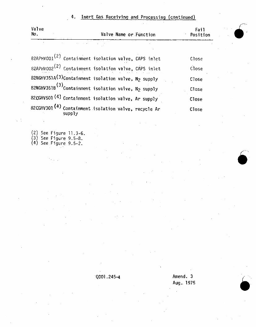
4. Inert Gas Receiving and Processing (continued)
ValveNo. Valve Name or Function
FailPosition
82APHVO01(2) Containment
82APHVO02(2) Containment
82NGHV351A(3)Containment
82NGHV351B (3) Containment
82.CGHV501 (4) Containment
82CGHV301 (4) Containmentsupply
(2) See Figure 11.3-6.(3) See Figure 9.5-8.(4) See Figure 9.5-2.
isolation
isolation
isolation
isolation
isolation
isolation
valve,
valve,
valve,
valve,
valve,
valve,
CAPS inlet
CAPS inlet
N2 supply
N2 supply
Ar supply
recycle Ar
Close
Close
Close
Close
Close
Close
QOOi .245-4 Amend. 3Aug. 1975 (

C'0
5. Steam Generator/Steam Generator Auxiliary Heat Removal Systems
Va 1 ve
Auxiliary FeedwaterPump Inlet
Alternate AuxiliaryFeedwater Pump Inlet
Auxiliary Feedwater PumpDischarge
Auxiliary FeedwaterPump Recirculation
Auxiliary FeedwaterSupply
Drive Turbine Steam
Supply
Superheater Outlet
Superheater Inlet
Evaporator Inlet
Feedwater Inlet
Evaporator Water Pump
Superheater Outlet
Normal OperatingPosition
Open
Cl osed
Open
Closed
Closed**
Closed**
Open
Open
Open
Open
Closed
Closed
Closed
Closed
Final Fail PositionAfter Loss ofCompressed Air*
Open
Closed
In Place
Open
Open
Open
Closed
Closed
Open
Closed
Closed
Closed
Closed
Closed
Function
Isolation
Isolation
Isblation
Isolation
Isolation
Isolation
Isolation
Isolation
Isolation
Isolation
Isolation
Pelief (PowerOperation)
Relief (PowerOperation)
Relief 'PowerOperation)
/
0
Evaporator Outlet
Steam Drum Outlet
* Air stored in an accumulator for emergency
**Open during SGAHRS Heat Removal Operation.operation of the valve.
QOOI .245-5 Amend. 8Dec. 1975

6. Recirculating Gas Cooling System
Air operated safety related valves are shown on Figures 9.16-3*through 9.16-7.
Table 9.16-3 list active air operated safety related valves withtheir "Preferred Direction"
.7. Heating, Ventilating and Air Conditioning
Air operated safety related valves are shown on Figure 9.6-1,9.6-4, 9.6-5, 9.6-7a.
There are no active air operated safety related valves in theHVAC system.59,
Amend. 59Dec. 1980
QO01 245-6