nuscale final safety analysis report - nrc: home page
TRANSCRIPT

NuScale Final Safety Analysis Report Mechanical Systems and Components
Tier 2 3.9-1 Revision 1
3.9 Mechanical Systems and Components
3.9.1 Special Topics for Mechanical Components
This subsection addresses information concerning methods of analysis for Seismic Category I components and supports, including those designated as American Society of Mechanical Engineers (ASME) Boiler and Pressure Vessel Code (BPVC), Section III (Reference 3.9-1), Division 1 Class 1, 2, 3, subsection NG for core support structures, subsection NF for supports, and those not covered by the ASME BPVC as discussed in NUREG 0800 Standard Review Plan (SRP) 3.9.1. Information also is presented concerning design transients for ASME BPVC Class 1 and core support structure components and supports.
The NuScale Power Plant design meets the relevant requirements of the following General Design Criteria (GDC) of 10 CFR 50, Appendix A:
• GDC 1, as it relates to components being designed, fabricated, erected, constructed, tested, and inspected in accordance with the requirements of applicable codes and standards commensurate with the importance of the safety-related functions to be performed. Compliance with GDC 1 is discussed in Section 3.1.
• GDC 2, as it relates to mechanical components of systems being designed to withstand seismic events without loss of capability to perform their safety-related functions. Pursuant to GDC 2, mechanical components are designed to withstand the loads generated by natural phenomena as discussed Section 3.1.1.
• GDC 14, as it relates to the reactor coolant pressure boundary (RCPB) being designed so as to have an extremely low probability of abnormal leakage, of rapidly propagating failure, and of gross rupture. As discussed below, the design transients and consequent loads and load combination with appropriate ASME code service limits, provide reasonable assurance that the RCPB is designed to maintain the stresses within acceptable limits to accommodate the system pressures and temperatures expected from normal operation including anticipated operational occurrences (AOOs), infrequent events, and accident loading conditions such as safe shutdown earthquake (SSE).
• GDC 15, as it relates to the mechanical components of the reactor coolant system (RCS) being designed with sufficient margin to ensure that the design conditions of the RCPB are not exceeded during any condition of normal operation, including AOOs. The overpressure protection features are designed with sufficient capacity to prevent the RCPB from exceeding 110 percent of design pressure during normal operations and AOOs. Safety-related mechanical components are designed to remain functional under postulated combinations of normal operating conditions, AOOs, postulated pipe breaks, and seismic events in compliance with the requirements of GDC 14 and 15.
• 10 CFR 50, Appendix B, Section III, as it relates to quality of design control. Section 17.5 satisfies the requirements of 10 CFR 50, Appendix B, to ensure that SSC are designed, procured, fabricated, inspected, erected, and tested to standards commensurate with their contribution to plant safety.
• 10 CFR 50, Appendix S, as it relates to the suitability of the plant design bases for mechanical components established in consideration of site seismic characteristics.

NuScale Final Safety Analysis Report Mechanical Systems and Components
Tier 2 3.9-2 Revision 1
This requirement is met by including design-transient seismic events as part of the design basis for withstanding the effects of natural phenomena.
3.9.1.1 Design Transients
The design transients define thermal-hydraulic conditions (i.e., pressure, temperature, and flow) for the NPM. Bounding thermal-hydraulic design transients are defined for components of the RCPB. The number of cycles for each design transient is based on a plant life of 60 years. The transients are defined for safety-related equipment design purposes and are intended to provide a bounding representation of the NPM operation.
The following operating condition categories, as defined in the ASME BPVC, Section III (Reference 3.9-1), apply to Class 1 and 2 components, the containment vessel (CNV), supports, reactor vessel internals (RVI), piping, and valves inside and outside of containment up to the outermost containment isolation valve:
• ASME Service Level A
Service Level A includes conditions associated with events that are planned to occur due to routine operation of the plant. Examples include startup, power maneuvers, and shutdown.
• ASME Service Level B
Service Level B includes conditions associated with transients that occur often enough that the operability of the plant is not affected. These transients will not result in damage requiring repairs.
• ASME Service Level C
Service Level C events may result in permanent deformation and repairs may be required to correct large deformations in areas of structural discontinuity.
• ASME Service Level D
Service Level D events may result in gross deformation and dimensional instability. Repair or replacement of components may be necessary to correct mechanical damage.
• Test Conditions
These conditions include pressure tests required by ASME BPVC, Section III (Reference 3.9-1), and other tests required by the design specifications.
Table 3.9-1, Summary of Design Transients, lists the design transients by ASME service level and includes the number of events over the design life of the plant for each transient. Load combinations and their acceptance criteria are given in Section 3.9.3 for mechanical components and associated supports and in Section 3.12 for piping systems.
NuScale Final Safety Analysis Report Mechanical Systems and Components
Tier 2 3.9-3 Revision 1
The Service Level A and B transients are representative of events that are expected to occur during plant operation. These transients are severe or frequent enough to be evaluated for component cyclic behavior and equipment fatigue life, and the analyzed conditions are based on a conservative estimate of the frequency and magnitude of temperature and pressure changes. When used as a basis for component fatigue evaluation, the bounding transients provide confidence that the component is appropriate for its application over the design life of the plant. Service Level C and D conditions are not typically included in fatigue evaluations in accordance with the ASME BPVC, Section III (Reference 3.9-1). For select component and transient combinations, Service Level C events are evaluated against Level B stress limits. This selection is made either because the event contains significant stress cycles or the transient is considered a normal design operation for that component. The following sections describe the assumptions used in thermal-hydraulic analysis for each Service Level.
3.9.1.1.1 Service Level A Conditions
Service Level A Transient 1 - Reactor Heatup to Hot Shutdown
This transient covers the heatup and pressurization from transition mode to hot shutdown. The event begins with a depressurized reactor vessel filled with water. The CNV also is filled initially with water up to the elevation of the pressurizer baffle plate.
The CNV is pressurized to at-or-above the minimum pressure required to begin the containment drain process. The RCS is pressurized equivalently by adding nitrogen gas to the pressurizer. Once pressurizer heaters are actuated to increase RCS pressure, the nitrogen is removed through the reactor pressure vessel (RPV) high point degasification line and is replaced with steam. After the RCS has reached the hot shutdown temperature and normal operating pressure of 1850 psia, a system leakage test is performed per the requirements of ASME BPVC Section XI (Reference 3.9-2).
Service Level A Transient 2 - Reactor Cooldown from Hot Shutdown
This transient encompasses the cooling from hot shutdown to transition mode and is generally the reverse of the reactor heatup to hot shutdown. The temperature of the RCS is continually reduced by controlling the feedwater flow rate. The steam and feedwater flow rates are controlled to keep the cooling rate below the maximum of 100 degrees F/hr (200 degrees F/hr in the pressurizer). The RCS temperature changes also are limited to maintain subcooling between the pressurizer and RCS hot leg less than 250 degrees Fahrenheit. The chemical and volume control system (CVCS) is used to increase the boron concentration to shutdown levels and to add makeup to compensate for coolant shrinkage. The containment flooding and drain system is used to add pool water to containment to continue cooling the CNV and RPV.

NuScale Final Safety Analysis Report Mechanical Systems and Components
Tier 2 3.9-4 Revision 1
Service Level A Transient 3 - Power Ascent from Hot Shutdown
This transient covers the power ascent from hot zero power conditions in hot shutdown mode to 15 percent of full power at which point the control systems are placed in automatic mode. Automatic mode is expected to cover power levels above 15 percent of full power. Throughout this transient, the steam and feedwater flow rates are controlled to match the demanded load ramp, which is specified to be limited to 0.5 percent of full power per minute. The feedwater temperature remains at the condenser hot well temperature as the feedwater heaters are unavailable.
Service Level A Transient 4 - Power Descent to Hot Shutdown
This transient occurs as the reverse of the power ascent from hot shutdown. The transient covers the reactor conditions that span from 15 percent of full power to hot zero power conditions in hot shutdown mode. The lower limit of the power range where the reactor is under automatic control occurs at 15 percent of full power. Since the turbine is offline, steam produced by cooling the RCS is diverted through the turbine bypass valve. A uniform ramp decrease in power is specified to occur a maximum rate of 0.5 percent of full power per minute. Feedwater heating is not available as the turbine is offline and, therefore, the feedwater temperature is equal to the condenser hot well temperature.
Service Level A Transient 5 - Load Following
The reactor could be required to provide load following capabilities to match the electrical demand of the grid over a 24-hour period. The load begins at full power and ramps down to 20 percent of full power over two hours. The load then remains constant for up to ten hours before ramping back to full power over two hours. The load remains constant at full power for the remainder of a 24-hour cycle.
Service Level A Transient 6 - Load Regulation
Load regulation refers to fluctuations in load due to the plant participating in some form of grid frequency control. The frequency control transient is defined as a 10 percent of full power increase or decrease in load at 2 percent of full power per minute. This load regulation is a plant-wide capacity, thus the change in plant load is the total power change for all operating modules. Load regulation is provided while at a steady power level or while performing the ramp power changes required for load following. Reactor power will lag behind the step change in load demand.
Service Level A Transient 7 - Steady State Fluctuations
While operating at a steady load, there may be small fluctuations in RCS temperature and pressure. These fluctuations could be due to minor control system malfunctions, instrument drifts, small power variations, or other unplanned variations. The full-power, normal operating bands for RCS average temperature and pressurizer pressure are expected to be ±0.5 degrees Fahrenheit and ±5 psia.

NuScale Final Safety Analysis Report Mechanical Systems and Components
Tier 2 3.9-5 Revision 1
Service Level A Transient 8 - Load Ramp Increase
When the reactor is in automatic mode, the reactor will be capable of providing a load increase at a rate of 5 percent of full power per minute over the power range of automatic control, 15 to 100 percent of full power. A rate of 5 percent of full power per minute is an upper bound on the load increase rate for power maneuvers and is consistent with other pressurized water reactor designs. Throughout this transient, the pressure, average RCS temperature, and pressurizer level are under automatic control.
Service Level A Transient 9 - Load Ramp Decrease
When the reactor is in automatic mode, the reactor will be capable of providing a load decrease at a rate of 5 percent of full power per minute over the power range of automatic control, 15 to 100 percent of full power. A rate of 5 percent of full power per minute is an upper bound on the load decrease rate for power maneuvers and is consistent with other pressurized water reactor designs. Automatic control mode is initiated at 15 percent of full power. Feedwater temperature will decrease due to less feedwater heating as the power level decreases.
Service Level A Transient 10 - Step Load Increase
When the reactor is in automatic mode, the nuclear steam supply system components are designed to withstand the cycles associated with a 10 percent of full power step load increase. This transient could occur due to a disruption in the electrical grid. As load is increased, the imbalance between load and core power causes the RCS temperature and pressure to decrease. The pressurizer heaters will respond to a pressure decrease by increasing proportional heater output and energizing the backup heaters.
Service Level A Transient 11 - Step Load Decrease
Nuclear steam supply system components must also be capable of withstanding the cycles associated with a 10 percent of full power step load decrease. This transient could occur due to a disruption in the electrical grid. As load is decreased, the imbalance between load and core power causes the temperature and pressure to increase. The pressurizer will respond to any large pressure increase by reducing heater output and initiating normal spray flow.
Service Level A Transient 12 - Large Step Load Decrease
This transient occurs when there is a large decrease in the demanded load by the grid from full power down to 20 percent of full power. When the load decreases, steam pressure increases and steam flow rate decreases. RCS temperature and pressure increase due to the decrease in secondary heat removal. Some steam will likely need to bypass the turbine to prevent a reactor trip on high pressurizer pressure or level. The bypass load is ramped down at about 5 percent power per minute to give the reactor time to reduce power. There are two control signals to detect a large step load decrease and to regulate the bypass steam flow. An error

NuScale Final Safety Analysis Report Mechanical Systems and Components
Tier 2 3.9-6 Revision 1
signal between the demanded and actual turbine load will determine the need for steam bypass, and a signal will provide the expected bypass valve position as a function of the demanded load.
Service Level A Transient 13 - Refueling
During refueling, the containment vessel flange and reactor vessel flange are opened and the upper portion of the NuScale Power Module is lifted away from the lower portion, exposing the reactor core for refueling. This operation takes place in the refueling pool. There is a negligible thermal cycle on the RPV as the flanges are unbolted and cold pool water mixes in. For module handling operations to begin, the RCS must be in transition mode, below 200 degrees Fahrenheit. The maximum temperature change would then be 200 degrees Fahrenheit minus the minimum pool water temperature. There will be negligible thermal cycles for cold unbolting and re-bolting of the RPV flanges for reactor startup, because the RPV temperature will be near equilibrium with the surrounding reactor pool water following the duration of a refueling outage. There will also be stress cycles introduced by the module handling operations, such as module lifting, bolting, and unbolting.
Service Level A Transient 14 - Reactor Coolant System Makeup
The RCS makeup transient consists of the normal replenishment of RCS fluid due to minor leakage or for boron concentration adjustment by the CVCS makeup pumps. The CVCS continuously circulates coolant through the demineralizers and filters and back to the RCS. Makeup flow is required to maintain the pressurizer level, change the boron concentration, or adjust the RCS chemistry.
This transient begins when the CVCS makeup pumps are energized to add makeup coolant. The makeup coolant can be demineralized or borated water. CVCS flow is pumped to the RCS through the RCS injection line and to the pressurizer through the spray bypass line. The makeup water begins at low temperature before it is heated by the CVCS regenerative heat exchanger. The coolant returning to the RCS is colder during makeup compared to nonmakeup flows, and piping and components subjected to makeup flows experience thermal cycles.
Service Level A Transient 15 - Steam Generator Inventory Control from Hot Shutdown
This transient occurs while leaving a hold at hot shutdown. Normally, continuous feedwater and steam flows are used for steam generator (SG) inventory control when transitioning to and from hot shutdown. If there is an extended hold at hot shutdown, the decay heat generation may drop below the minimum capability of the secondary heat removal systems, thus securing the continuous feedwater and steam flows. Breaking the hold will initiate the feedwater flow again, which will provide cold feedwater to components that had already reached equilibrium with the hot RCS. The main steam isolation valves (MSIVs) are opened to the desired position and the feedwater and steam flows are operated continuously to achieve the objective. An option is to use the CVCS module heatup system to maintain the primary coolant temperature, which reduces the need to turn off feedwater flow and reduces the thermal cycles on RPV components. During a reactor cooldown
NuScale Final Safety Analysis Report Mechanical Systems and Components
Tier 2 3.9-7 Revision 1
due to decay heat removal system (DHRS) actuation, the DHRS cooldown may be interrupted by re-establishing feedwater flow to the SG. The feedwater flow is a continuous flow, providing inventory to the SG. This will be less severe for components, such as the feedwater plenum, since the plenum would already be at a cooler temperature due to the flow of DHRS condensate during the reactor cooldown.
Service Level A Transient 16 - High Point Degasification
There are two transients for the high-point degasification line, consisting of the normal operation venting of the pressurizer and shutdown degasification of the RCS. The normal operation venting transient involves periodically opening the valves in the high-point degasification line to remove non-condensable gases that have collected in the vapor space of the pressurizer. Prior to and during shutdown operations, the high-point degasification line is used to mechanically degas the RCS to remove gases from the pressurizer vapor space and dilute the concentration of hydrogen in the reactor coolant by venting and providing makeup from the CVCS.
Service Level A Transient 17 - Containment Evacuation
The containment evacuation system connects to the containment vessel nozzle with no internal piping and is used to add and remove gases. The containment evacuation transient is made up of three events: startup operation with air or nitrogen addition and removal, shutdown operation with air removal, and normal operation removal of water vapor or non-condensable gases. During startups and shutdowns, service air or nitrogen is added and removed through the containment evacuation system to control containment liquid levels. During normal operation, the line is used for continuous or sporadic removal of water vapor or gases to maintain a vacuum in the containment vessel. This ensures that water vapor leaked into the containment vessel does not condense and collect at the bottom. If there is leakage, then the containment evacuation system is expected to run, continuously or intermittently, until the leak is fixed during the next reactor shutdown.
Service Level A Transient 18 - Containment Flooding and Drain
The containment flooding and drain system connects to a CNV nozzle with piping extending from the top head of the CNV to the bottom for each module. The piping is used to add and remove water to and from the CNV. This transient is split into two events: containment flooding operations after shutdown and containment drain operations prior to startup. After shutdown, the containment flooding and drain containment isolation valves are opened and the pump transfers water from the reactor pool to the CNV. Prior to startup of the module, the containment flooding and drain system containment isolation valves are opened and containment is pressurized through the containment evacuation system penetration to the minimum pressure required or to provide adequate net positive suction head to the pump, which helps drain the CNV of water.

NuScale Final Safety Analysis Report Mechanical Systems and Components
Tier 2 3.9-8 Revision 1
3.9.1.1.2 Service Level B Conditions
Service Level B Transient 1 - Decrease in Feedwater Temperature
A decrease in feedwater temperature could occur due to many different malfunctions in the secondary side system. However, the bounding malfunction is the loss of feedwater heating. Such a failure at full power drops the feedwater temperature significantly, which quickly reduces the RCS temperature and adds reactivity due to the negative moderator temperature coefficient. The colder coolant and reactivity insertion cause core power to increase and can result in a reactor trip on high power. The secondary control system compensates for the lower feedwater temperature by adjusting the feedwater flow rate to reach the load demand setpoint. If a trip setpoint is not reached, reactivity feedback will allow the reactor power to re-adjust to match the demanded load.
Service Level B Transient 2 - Increase in Secondary Flow
An equipment or control system malfunction could cause an increase in secondary flow. A malfunction could be on the steam side, such as opening the turbine throttle valve, or on the feedwater side, such as opening the feedwater regulating valve or increasing the feedwater pump speed. Any of these malfunctions leads to an increase in feedwater flow rate, but the feedwater pressure could increase or decrease. One of the control valves opening leads to a feedwater pressure decrease while an increase in feedwater pump speed increases the feedwater pressure.
The bounding cases are the following: the complete opening of either the feedwater regulating valve, turbine throttle valve, or turbine bypass valve or the feedwater pump speed increasing to 100 percent. The RCS responds to an increase in secondary flow rate with a decrease in temperature and pressure. Reactivity feedback then causes an increase in reactor power.
There will also be a control system response for the secondary side. The steam superheat will fall below the setpoint and the actual SG load will be larger than the setpoint. The feedwater regulating valve and the turbine throttle valve will both close to try to match the superheat and load setpoints. Depending on the magnitude of the feedwater flow or steam flow increase and what caused the malfunction, this transient may lead to a turbine trip due to low superheat or a higher load than demanded. A reactor trip will also occur on low pressurizer level, low steam pressure, or high reactor power, and if the change in steam pressure causes the main steam and feedwater isolation valves to close, then the DHRS will be actuated.
Service Level B Transient 3 - Turbine Trip without Bypass
The turbine trip transient may be caused by any of several equipment or control system malfunctions. This transient covers the scenario where the turbine trip leads to a reactor trip. Once the turbine trips, the turbine stop valve shuts, stopping all steam flow and increasing steam pressure. The turbine bypass is postulated to be unavailable.

NuScale Final Safety Analysis Report Mechanical Systems and Components
Tier 2 3.9-9 Revision 1
The RCS pressure and temperature increase due to the loss of heat removal and the pressurizer level rises due to the expanding RCS fluid. The reactor will trip and actuate both trains of the decay heat removal system (DHRS) to remove decay heat and cool the RCS. The reactor safety valves (RSVs) do not open.
Service Level B Transient 4 - Turbine Trip with Bypass
The turbine trip transient may be caused by any of several equipment or control system malfunctions. This transient covers the scenario when the turbine trips and the turbine bypass flow is available. After switching to bypass flow, the feedwater temperature decreases due to the feedwater heaters being offline. Reactor power stabilizes at its original level. The reactor does not trip. Reactor power is then decreased at a rate consistent with the Service Level A Transient 9-Load Ramp Decrease. Feedwater heating is not available throughout the power decrease.
Service Level B Transient 5 - Loss of Normal AC Power
A loss of normal AC power consists of a loss of AC power with no credit taken for the backup power supply system. Under these circumstances the reactor trips, the containment isolation valves fail closed, and the DHR actuation valves fail open. The module reaches a safe shutdown state by dissipating the heat through the DHR condensers. Batteries supply power to the five emergency core-cooling-system (ECCS) valves (three reactor vent valves (RVVs) and two reactor recirculation valves (RRVs)) that hold the valves closed. Once battery power is supplied to the ECCS valves a 24 hour timer begins. After 24 hours, battery power is removed and the RVVs and RRVs fail open. Actuation of the ECCS establishes a two-phase, natural circulation loop. Steam generated in the RPV exits through the RVVs and condenses on the walls of the CNV. The condensed water returns to the RPV through the RRVs. Coincident losses of the DC power systems, EDS or EDNS, as well as delays in MPS actuations, are considered to determine bounding pressure and temperature responses for mechanical design.
Service Level B Transient 6 - Inadvertent Main Steam Isolation Valve Closure
An inadvertent closure of an MSIV will cause a sudden decrease in the secondary-side flow for the affected SG and an increase in flow in the other SG. The closed MSIV causes the SG pressure to increase. The reactor trips on either high-steam pressure or high-pressurizer pressure.
The RSVs do not lift. Both trains of the DHRS are actuated. The DHRS removes heat through the two SGs and rejects the heat to the reactor pool. The components of the DHRS are sized to remove decay heat and cool the RCS.
Service Level B Transient 7 - Inadvertent Operation of the Decay Heat Removal System
The inadvertent operation of the DHRS could occur in two ways. The first is the inadvertent opening of one of the DHRS actuation valves. Opening an actuation valve allows flow between the DHRS condenser and the steam line as the steam and feedwater pressures equalize. The initial pressure equalization in the

NuScale Final Safety Analysis Report Mechanical Systems and Components
Tier 2 3.9-10 Revision 1
secondary side causes a disruption in the primary temperature. Both DHRS trains actuate and the reactor trips. The second way to inadvertent DHRS actuation is by the module protection system (MPS) sending a signal to actuate the DHRS by closing the MSIVs and feedwater isolation valves and opening the DHRS actuation valves on both trains of the DHRS. This results in the full-power operation of both trains of the DHRS. The DHRS actuation signal causes a reactor trip. The RSVs do not lift for either occurrence.
Service Level B Transient 8 - Reactor Trip from Full Power
A reactor trip from full power could be caused by multiple spurious sensor signals to the module protection system (MPS), or a spurious trip signal from the MPS, or miscellaneous failures that cause a reactor trip setpoint to be reached and are not already included in other transients. Once the trip begins, the control rods drop into the core to take the core subcritical. This reduces the core thermal power to decay heat and causes the hot- and cold-RCS temperatures to converge close to the average RCS temperature. Cooling is then initiated by one of two methods, either normal feedwater or actuating the DHRS. If the DHRS is actuated, then a containment isolation signal may also be generated. When circulating feedwater through the SGs, the steam produced is directed through the turbine bypass valve to the condenser. The steam and feedwater flow rates are controlled to keep the cooling rate below the maximum of 100 degrees F/hr (200 degrees F/hr in the pressurizer). This transient ends once the reactor reaches approximately steady hot shutdown conditions. Any cooldown from there is accounted for in the cycles of the cooldown from hot shutdown. If the DHRS is actuated for a more severe failure, heat is removed through the DHRS condenser to the pool.
Service Level B Transient 9 - Control Rod Misoperation
This transient includes misoperations of the control rod assemblies (CRAs), such as the drop of a single CRA, the drop of a bank of CRAs, withdrawal of a single CRA, or withdrawal of a CRA bank. The CRA adds significant negative reactivity to the core that quickly reduces reactor power. Such a reduction in power leads to a decrease in RCS temperature and pressure. The decreasing temperature leads to a reactivity insertion due to the negative moderator temperature coefficient. The reactor will likely trip on low pressure or pressurizer level. However, if the rod worth is low enough, the reactor may reach a new steady state at the original power level but with a lower average RCS temperature. Removal of decay heat is by feedwater flow.
Service Level B Transient 10 - Inadvertent Pressurizer Spray
The inadvertent pressurizer spray transient entails, either through equipment failure or operator error, actuation of continuous pressurizer spray. With the spray control valve fully open, spray flow at the maximum design flow and the minimum expected temperature is provided to the pressurizer. The pressurizer heaters energize to counteract the decrease in pressurizer pressure. A reactor trip on low pressurizer pressure will occur. The low pressurizer pressure also triggers containment isolation and actuates both trains of the DHRS. Once the reactor trips, it will take the operators some time to identify the failure that caused depressurization. Removal of decay heat is by the DHRS.

NuScale Final Safety Analysis Report Mechanical Systems and Components
Tier 2 3.9-11 Revision 1
Service Level B Transient 11 - Cold Overpressure Protection
When the RPV is at low temperatures, the metal is more prone to brittle failure. To prevent this type of failure, lower maximum pressure limits are implemented when the RPV is at low temperature. Cold overpressurization could be caused by equipment malfunctions or operator error that cause excessive heat or inventory to be added to the RCS. The RVVs are providing protection against low-temperature overpressurization.
If the RCS is at or below the low-temperature overpressure protection enable temperature and the RCS pressure is at or above the low temperature overpressure protection pressure setpoint, the RVVs will open to relieve the pressure by blowing down to the CNV. Interlocks in the control system will prevent this action when the reactor coolant is above the low temperature overpressure protection enable temperature. When the RVVs open, all of the components within the RPV experience a rapid decrease in fluid pressure. The CNV pressure will increase as it receives coolant from the RPV and once the RCS pressure and CNV pressure reach equilibrium, the RRVs will be opened.
Service Level B Transient 12 - CVCS Malfunctions
This transient includes malfunctions of the CVCS that can cause an increase in RCS inventory or addition of cooler water to the RCS. An increase in RCS inventory could result from a spurious makeup pump operation, excessive charging, or a failure in the letdown line to compensate for the increase in inventory. These events could cause the pressurization of the RCS and a CVCS isolation or reactor trip will likely occur. If there is a malfunction of the pressurizer spray and the RCS pressure is high enough to reach the RSV setpoint, the RSVs will lift to release pressure. Another CVCS malfunction transient is possible if recirculation flow is stopped due to the malfunction of the CVCS recirculation pumps. A full or partial valve closure in the letdown line is also specified, which limits the amount of letdown flow. This would allow colder makeup water to be pumped to the RCS using the makeup pumps, with limited heat addition through the regenerative heat exchanger. Depending on the reactor power level and primary flow rate, the addition of colder makeup water could affect the reactivity, which could possibly result in a reactor trip on high reactor power.
3.9.1.1.3 Service Level C Conditions
Service Level C Transient 1 - Spurious ECCS Valve Actuation
The ECCS consists of three RVVs and two RRVs. In the event of an inadvertent actuation of an RVV or RRV, the inadvertent actuation block feature provides mechanical pressure-locking to prevent opening of the valve when the RCS and CNV are at normal operating pressure. The inadvertent actuation block is treated as a passive device and is not considered for single active failure. The inadvertent opening of a single ECCS valve is an event analyzed in 15.6.6. The opening of a single RVV or RRV could be caused by a malfunction of passive equipment, such as failure of the inadvertent actuation block, if an ECCS signal is present or if DC power is lost. This event causes a decrease of RCS inventory due to the blowdown of RCS

NuScale Final Safety Analysis Report Mechanical Systems and Components
Tier 2 3.9-12 Revision 1
fluid to the CNV. The bounding operating condition for the opening of an RVV or RRV is full power operation. When the ECCS valve opens, a reactor trip signal is generated on either high containment pressure or low pressurizer pressure. The high containment pressure signal would also cause a containment isolation and DHRS actuation. The open ECCS valve allows reactor coolant to blow down into the CNV. As the hot steam contacts the CNV walls, it condenses to liquid and accumulates in the bottom of the CNV. The CNV wall is cooled by convection to the surrounding reactor pool. The remaining ECCS valves open when either the liquid accumulating in the CNV reaches the high CNV water level setpoint or the RCS liquid level decreases to the low RCS level setpoint. This configuration establishes a two-phase, natural recirculation loop that provides cooling for the RCS through the RVVs and keeps the core covered by returning liquid to the RPV through the RRVs.
Simultaneous failures that result in the inadvertent opening of multiple ECCS valves when the RCS is at normal operating pressure is beyond design basis with respect to identifying initiating events.
Service Level C Transient 2 - Inadvertent Opening of a Reactor Safety Valve
The inadvertent opening of one of the RSVs causes the RCS to quickly depressurize as the primary coolant blows down to the CNV. The reactor will trip likely due to high containment pressure or low pressurizer pressure. The high containment pressure causes a containment isolation and DHRS actuation signal. The hot vapor entering the CNV will condense on the walls and fall to the bottom of the CNV. When either the low RCS or high CNV liquid level setpoints are reached, all five ECCS valves will open. The open valves establish the ECCS two-phase, natural recirculation loop. Decay heat is removed by the vapor moving through the RVVs to the CNV and the core is kept covered by the liquid returning to the RPV through the RRVs. Removal of decay heat is expected through the containment wall and peak pressure in the CNV is kept below design pressure.
Service Level C Transient 3 - CVCS Pipe Break
The CVCS Pipe Break is characterized by a rupture of a pipe penetrating the RCPB. The break could occur inside or outside of containment. A break inside containment maximizes the dynamic response of the RPV and RVI and captures a pressure and thermal cycle for the CNV and components inside containment. A break outside of containment could cause stresses on the components just outside of containment. In this transient, the RCS depressurizes through the break and the level in the pressurizer decreases. The reactor trips due to either low pressurizer pressure or level or high containment pressure, and the DHRS is actuated. The ECCS may eventually actuate based on either a low RCS liquid level or a high water level in containment. Removal of decay heat is expected through the containment wall and peak pressure in the CNV is kept below design pressure.
Service Level C Transient 4 - Steam Generator Tube Failure
The steam generator tube failure (SGTF) transient is bounded by the double-ended failure of a SG tube. The term “failure” is used here to include both a tube collapsing due to higher external pressure and a tube bursting due to higher inner pressure.
NuScale Final Safety Analysis Report Mechanical Systems and Components
Tier 2 3.9-13 Revision 1
Multiple simultaneous SGTFs are considered beyond design basis. In this transient, the RCS blows down into the SG. A reactor trip would occur quickly due to high steam pressure, low pressurizer pressure, or low pressurizer level. Both trains of the DHRS will be actuated to remove the decay heat as normal cooldown using feedwater flow is not possible with SGTF. A SGTF incapacitates one train of the DHRS, but cooldown is still accomplished with the other train. Components within the RPV will experience a decrease in pressure when the SG tube fails and the RCS blows down to the SG. Once the MSIVs and feedwater isolation valves close and the DHRS actuates, the pressure decrease will slow to be only a function of the RCS cooldown rate. The cooldown rate is determined by the performance of the single DHRS train.
3.9.1.1.4 Service Level D Conditions
Service Level D Transient 1 - Steam Piping Failures
A main steam line break could cover a wide range of break types. A rupture will cause an increase in steam flow rate and will reduce the SG inventory. A break inside containment is not postulated to occur because of leak before break detection on these lines. A break outside of containment could cause stresses on the components just outside of containment. RCS temperature and pressure briefly decrease due to the excess heat removal provided by the steam line blowdown. A break will quickly cause a reactor trip on low steam pressure or high containment pressure. Once the reactor is tripped, both trains of the DHRS will be activated. One train of the DHRS will be ineffective due to the break. A single train of the DHRS will be capable of removing the decay heat from the reactor. The RSVs do not lift and there is no ECCS actuation. Removal of decay heat is by the DHRS and peak pressure in the CNV is kept below design pressure.
Service Level D Transient 2 - Feedwater Piping Failures
A feedwater line break could cover a wide range of break types. Due to the interaction of the DHRS and feedwater system, the spectrum of feedwater piping breaks includes breaks in the DHRS. A feedwater piping break inside containment is not postulated to occur because of leak-before-break detection on these lines, but a break in the DHRS condensate line inside containment is postulated. A break outside of containment could cause stresses on the nearby components. RCS temperature and pressure briefly decrease due to the excess cooling provided by the feedwater line blowdown. Once the quick blowdown phase is over, the transient results in heating and pressurization of the RCS. A break will quickly cause a reactor trip on low steam pressure or high containment pressure. Once the reactor is tripped, both trains of the DHRS will be activated. One train of the DHRS will be ineffective due to the line break. A single train of the DHRS will be capable of removing the decay heat from the reactor. The RSVs do not lift and there is no ECCS actuation. Peak pressure in the CNV is kept below design pressure.
Service Level D Transient 3 - Control Rod Assembly Ejection
This transient covers a spectrum of possible control rod ejection scenarios in order to find the most limiting case. Scenarios must be considered at different power

NuScale Final Safety Analysis Report Mechanical Systems and Components
Tier 2 3.9-14 Revision 1
levels, fuel burnups, and rod configurations. The most reactive control rod for a given scenario is postulated to be ejected from the core. Removing the control rod causes a local reactivity insertion that leads to a pressure increase. Once the rod is ejected, there will be a delay before the module protection system trips the reactor. The trip could be caused by high reactor power or high-rate power change.
Service Level D Transient 4 - Combustible Gas Detonation
This transient covers the CNV and components necessary to maintain safe shutdown. The CNV and components must withstand the environmental conditions created by the burning of hydrogen within the first 72 hours of any design basis event and maintain containment structural integrity and safe shutdown capability.
A typical design basis event where combustible gas control is relevant is any event that results in ECCS actuation. Initiating events that result in ECCS operation include LOCAs, spurious valve openings, and a loss of all DC power. Regardless of the initiating event, the outcome is similar: the ECCS successfully actuates and maintains RPV liquid level above the top of the core. Because heat removal from the containment is very effective, temperatures will usually decrease rapidly. Subatmospheric pressure in the containment is expected within a few hours after event initiation.
Continued operation and long term cooling by the ECCS will result in a stable condition. Aside from temperature gradually approaching the reactor pool temperature, the only other long term change in the containment condition under ECCS operation is the accumulation of radiolytically generated gases. Radiolytic production of gases is capable of creating a flammable atmosphere soon after event initiation. As radiolytic production continues, a higher pressure flammable atmosphere becomes possible. At 72 hours after event initiation sufficient oxygen could be produced through radiolysis to create a flammable atmosphere.
The production of hydrogen and oxygen from radiolysis following a reactor shutdown and activation of ECCS, in combination with the low temperature and initial pressure of the containment, can lead to the formation of a combustible atmosphere. Once sufficient oxygen is produced and an ignition source is available deflagration and detonation could occur as well as a deflagration-to-detonation transition.
A deflagration propagates at subsonic speeds, resulting in a quasi-static pressurization of the CNV and SSC inside containment. This event is best simulated as a suddenly applied force, which remains on the structure indefinitely. Pressure reflection is not considered for subsonic events because these do not attain appreciable momentum to cause an amplified reflected pressure pulse. This is bounded by analysis of detonations.
A detonation results in spherically expanding pressure waves travelling at the Chapman-Jouguet (C-J) speed, leading to incident pressure waves that are twice the peak pressure of a deflagration. Reflected C-J pressure waves are further amplified upon impacting a hard surface. This is considered an ASME Level C event.
NuScale Final Safety Analysis Report Mechanical Systems and Components
Tier 2 3.9-15 Revision 1
Deflagration-to-detonation transition (DDT) is a condition resulting when a gaseous mixture burns leading to flame acceleration that reaches a sonic or supersonic condition where the deflagration transitions to a detonation. If the DDT occurs near a reflecting surface, a significant amplification above the peak reflected C-J pressure is possible due to pre-compression of the unburned gases ahead of the shock front. This is considered an ASME Level D event.
The initial conditions are determined from the optimum temperature and pressure that produces the largest pressure pulse. The reactor has tripped, ECCS has been activated and the NPM is cooling to reactor pool temperature.
For design purposes, this transient is specified to occur one time over the 60 year life of the plant. The expected outcome is that the ECCS operation continues.
3.9.1.1.5 Test Conditions
Primary Side Hydrostatic Test
The initial primary side hydrostatic test consists of pressurizing the RPV and the reactor coolant system to a minimum of 125 percent of design pressure and a water temperature of at least 70 degrees Fahrenheit to a maximum of 140 degrees Fahrenheit. The testing complies with ASME BPVC Section III (Reference 3.9-1), Article NB-6000 and Non-mandatory Appendix G for the minimum testing temperature of RTNDT +60 degrees Fahrenheit.
This hydrostatic test takes place in the fabrication shop prior to the first startup, with the RPV filled with water.
The RPV is designed for 10 cycles of this type of hydrostatic test. This hydrostatic test must be performed before the first startup and extra cycles are added in the event that significant repairs require additional tests.
The system leakage tests required by ASME BPVC Section XI are performed at nominal operating pressure and temperature, are not considered hydrostatic tests and, therefore, are not included in the number of occurrences.
Secondary Side Hydrostatic Test
The initial, secondary-side, hydrostatic test consists of pressurizing the secondary side to a minimum of 125 percent of design pressure and a water temperature of at least 70 degrees Fahrenheit to a maximum of 140 degrees Fahrenheit. The testing complies with ASME BPVC Section III (Reference 3.9-1), Article NB-6000 and Non-mandatory Appendix G for the minimum testing temperature of RTNDT +60 degrees Fahrenheit.
This hydrostatic test takes place in the fabrication shop prior to the first startup, with the secondary side filled with water.

NuScale Final Safety Analysis Report Mechanical Systems and Components
Tier 2 3.9-16 Revision 1
The secondary side is designed for 10 cycles of this type of hydrostatic test. This hydrostatic test must be performed before the first startup and extra cycles are added in the event that significant repairs require additional tests.
The system leakage tests required by ASME BPVC Section XI are performed at nominal operating pressure and temperature, are not considered hydrostatic tests and, therefore, are not included in the number of occurrences.
Containment Hydrostatic Test
The initial containment vessel hydrostatic test consists of pressurizing the containment vessel to a minimum of 125 percent of design pressure and a water temperature of at least 70 degrees Fahrenheit to a maximum of 140 degrees Fahrenheit. The testing complies with ASME BPVC Section III (Reference 3.9-1), Article NB-6000 and Non-mandatory Appendix G for the minimum testing temperature of RTNDT +60 degrees Fahrenheit.
This hydrostatic test takes place in the fabrication shop prior to the first startup, with the CNV filled with water. If the CNV is hydrostatically tested with the RPV installed, the RPV (both primary and secondary sides) must be vented to the CNV to preclude a differential pressure external to the RPV.
The containment vessel is designed for 10 cycles of this type of hydrostatic test. This hydrostatic test must be performed before the first startup and extra cycles are added in the event that significant repairs require additional tests.
The system leakage tests required by ASME BPVC Section XI are performed at nominal operating pressure and temperature, are not considered hydrostatic tests and, therefore, are not included in the number of occurrences.
3.9.1.2 Computer Programs Used in Analyses
The computer programs used by NuScale in the dynamic and static analyses of mechanical loads, stresses, and deformations, and in the hydraulic transient load analyses of seismic Category I components and supports, are listed below.
The development, procurement, testing, and maintenance of computer programs used in these analyses are completed in compliance with an established quality-assurance program described in Chapter 17. Computer program acceptability is pre-verified or the results verified with the design analysis for each application. Pre-verified computer programs are controlled using a software configuration management process. Methods of software design verification include: software design reviews, alternate calculations, and qualification testing.
In establishing its program for design control and verification, NuScale commits to compliance with NQA-1-2008 and NQA-1a-2009 addenda, Requirement 3, Sections 100 through 900, and the standards for computer software in NQA-1-2008 and NQA-1a-2009 addenda, Part II, Subpart 2.7 and Subpart 2.14 for Quality Assurance requirements for commercial grade items and services. Delegated responsibilities may be performed
NuScale Final Safety Analysis Report Mechanical Systems and Components
Tier 2 3.9-17 Revision 1
under an approved supplier's or principal contractor's quality assurance program, in which case the supplier is responsible for the control of computer programs used.
The following computer programs are used by NuScale.
ANSYS - The ANSYS Inc. ANSYS software package includes Mechanical, CFX, Fluent, ICEM CFD, Design Modeler, Workbench and Help. ANSYS is a pre-verified and configuration managed finite element analysis program used in the design and analysis of safety related components. The use of this program in structural and seismic analyses is discussed in Sections 3.7.2, 3.8.4, and its use in piping stress analyses is discussed in Section 3.12.4.
AutoPIPE - Bentley AutoPIPE Nuclear is pre-verified and configuration managed, and is used for performing stress analysis on piping systems throughout the NuScale power plant. This includes static and dynamic analyses for fluid and thermal transients and seismic accelerations. The use of this program in piping analysis is discussed in Section 3.12.4.
NRELAP5 - NRELAP5 is NuScale's proprietary system thermal-hydraulics code for use in safety-related design and analysis calculations, and is pre-verified and configuration managed. NRELAP5 is based on RELAP5-3D, a product of Idaho National Lab. The code permits simulation of single-phase or two-phase systems and includes many generic component models, which can be used in transient dynamic analyses. The development, use, verification, validation, and code limitations of this program are discussed in Section 15.0.2.
The following additional programs are used by suppliers:
RspMatch2009 - RspMatch2009 is commercially available from GeoMotions, LLC and is used for response spectral matching and adjusting seismic acceleration time histories.
SAP2000 - SAP2000 is commercially available from Computers and Structures, Inc. and performs finite element analysis for non-seismic load analyses and the design of structures. The use of this program is discussed in Sections 3.7.2 and 3.8.4.
SASSI2010 - SASSI2010 is commercially available and is used for the numerical analysis of the soil-structure interactions. The use of this program in seismic analyses is discussed in Sections 3.7.2 and 3.8.4.
SHAKE2000 - SHAKE2000 is commercially available and is used to calculate the strain-compatible soil properties and in-layer response acceleration time histories for the soil-structure interaction analyses of the NuScale structures.
EMDAC - EMDAC is a finite element analysis code produced by Curtiss-Wright Electro-Mechanical Division, and is used for the seismic structural analysis of the control rod drive mechanisms (CRDM).
Simulink - The Multiphysics Simulink computer program is used to simulate the operating dynamics of the CRDM, and is operated in a MatLab environment.
NuScale Final Safety Analysis Report Mechanical Systems and Components
Tier 2 3.9-18 Revision 1
For computer programs used in Section 3.7 Seismic design, see Section 3.7.5.
3.9.1.3 Experimental Stress Analysis
Experimental stress analysis is not used for the NuScale Power Plant design.
3.9.1.4 Considerations for the Evaluation of Service Level D Condition
The analytical methods used to evaluate stresses for Seismic Category I systems and components subjected to Service Level D condition loading are described in Section 3.9.3.
3.9.2 Dynamic Testing and Analysis of Systems, Components, and Equipment
This section presents the criteria, testing, and dynamic analyses employed to ensure the structural and functional integrity of piping systems, mechanical equipment, and reactor internals and their supports under dynamic and vibratory loading, including those due to fluid flow during normal plant operation, transient conditions and postulated seismic events. Section 14.2 contains test abstracts that describe in general terms the planned tests that will be performed and describes the programmatic controls that will be used to develop the individual tests.
The NuScale Power Plant design complies with the relevant requirements of the following regulations, including the General Design Criteria (GDC) of 10 CFR 50, Appendix A:
• GDC 1 and 10 CFR 50.55a, as they relate to the testing of systems and components to quality standards commensurate with the importance of the safety-related functions to be performed. The Quality Assurance Program Description, in accordance with 10 CFR 50, Appendix B, addresses the quality standards applied to the dynamic testing and analysis of SSC.
• GDC 2 and 10 CFR 50, Appendix S, as they relate to structures, systems, and components (SSC) designed to withstand appropriate combinations of the effects of normal and accident conditions with the effects of natural phenomena without losing the ability to perform their safety functions. Pursuant to GDC 2, mechanical components are designed to withstand the loads generated by natural phenomena as discussed in Section 3.1.1.
• GDC 4 as it relates to SSC being appropriately protected against the dynamic effects of discharging fluids. As discussed in FSAR Section 3.6, the NuScale Power Plant design appropriately protects SSC against dynamic effects, including the effects of missiles, pipe whipping, and discharging fluids, which may result from equipment failures and from events and conditions outside the nuclear power unit .
• GDC 14 as it relates to SSC of the RCPB being designed to have an extremely low probability of rapidly propagating failure or of gross rupture. Section 3.9.2 addresses dynamic testing of components of the reactor coolant pressure boundary to ensure that they will withstand the applicable design-basis seismic and dynamic loads in combination with other environmental and natural phenomena loads without leakage, rapidly propagating failure, or gross rupture.

NuScale Final Safety Analysis Report Mechanical Systems and Components
Tier 2 3.9-19 Revision 1
• GDC 15 as it relates to the reactor coolant system being designed with sufficient margin to ensure that the RCPB is not breached during normal operating conditions, including AOOs. The RCPB is designed to resist seismic, LOCA, and other environmental loads. Dynamic analyses are described to confirm the structural design adequacy of the reactor coolant pressure boundary. Vibration, thermal expansion, and dynamic effects testing are also described to verify the design.
• 10 CFR 50, Appendix B, as it relates to quality assurance in the dynamic testing and analysis of systems, structures, and components. The NRC-approved NuScale Quality Assurance Program Description discussed in Section 17.5 satisfies the requirements of 10 CFR 50, Appendix B, to ensure that SSC are designed, procured, fabricated, inspected, erected, and tested to standards commensurate with their contribution to plant safety.
3.9.2.1 Piping Vibration, Thermal Expansion, and Dynamic Effects
Piping systems can be damaged by thermal expansion and vibrations due to transient events such as pipe breaks, valve closure, etc. This section addresses the pre-operational testing, and initial startup testing that is performed to verify that the vibrations and thermal expansion and contraction of the as-built piping systems are bounded by the design requirements. The piping systems tested include:
• ASME BPVC, Section III (Reference 3.9-1), Class 1, 2, and 3 piping systems identified in Table 3.2-1.
• other high-energy piping systems inside Seismic Category 1 structures or those whose failure would reduce the functioning of any Seismic Category I plant feature to an unacceptably level. See Section 3.6.1.
• Seismic Category I portions of moderate-energy piping systems located outside of containment identified in Table 3.2-1 and Section 3.6.1.
The test program, as described in Section 14.2, verifies that the Class 1, Class 2, Class 3, and other high-energy and Seismic Category 1 piping systems meet functional design requirements and that piping vibrations and thermal expansions are within acceptable levels and will withstand dynamic effects due to operating transients. Piping systems are validated through a series of checks, inspections, and tests, as follows:
• The first validation step is during the manufacturing process at the manufacturing facility and during the construction. The piping systems and other components are inspected to verify the correct assembly and to record the initial positions under cold conditions.
• The second validation step is plant heat up, whereupon the plant is heated to normal operating temperatures. Expansion and contraction of the systems and components is monitored and recorded to verify that it is within the assumed conditions identified in the analyses.
• The third validation step is performance tests. The systems are operated to verify the performance of critical SSC such as valves, controls, and auxiliary equipment. This phase of testing includes transient tests as outlined in Chapter 14 to identify unacceptable expansion and contraction, noise, vibration, and stresses which are not bounded by the design analyses.

NuScale Final Safety Analysis Report Mechanical Systems and Components
Tier 2 3.9-20 Revision 1
The initial test program is described in Section 14.2. The vibration, thermal expansion, and dynamic effect elements of this test program, summarized below, are performed during Phase I pre-operational testing and Phase II initial startup testing.
Phase I - Pre-operational Testing
Preoperational tests are performed to demonstrate that the piping system components meet functional design requirements, and that piping vibrations and thermal expansions and contractions are bounded by the analyses. If the design basis parameters are not bounding compared to the measured values, then corrective actions (i.e. reanalyzing with as-built values) are implemented and the systems are retested.
Phase II - Initial Startup Testing
Initial startup testing is performed after the reactor core is loaded into a NuScale Power Module. These Phase II tests establish that the vibration level and piping reactions to transient conditions are acceptable and bounded by the analyses. If the vibration levels are not bounded, the analyses use the vibration level from the testing as input and verify that the design is acceptable.
3.9.2.1.1 Piping Vibration Details
3.9.2.1.1.1 Piping Included in Comprehensive Vibration Assessment Program
ASME Code Class 1, 2, and 3 piping systems that are part of the NuScale Power Module are included within the scope of the NuScale Comprehensive Vibration Assessment Program (CVAP) (Reference 3.9-5) Piping systems that meet the screening criteria for applicable flow induced vibration mechanisms are evaluated in the analysis program. If a large margin of safety is not demonstrated, prototype testing is performed in accordance with the CVAP measurement program and the requirements of Part 3 of ASME OM-2012, Division 2 (OM Standards).
NuScale Power Module components, piping, and supports with a high degree of safety margin are excluded from testing in the prototype measurement program, consistent with the overall measurement program objectives of validating relevant analytical inputs, results, and margins of safety.
3.9.2.1.1.2 Piping Not Included in Comprehensive Vibration Assessment Program
For ASME Code Class 3 piping that is not part of the NuScale Power Module (there is no Code Class 1 or 2 piping which is not part of the NuScale Power Module) and other ASME B31.1 piping outside of containment which requires vibration testing, vibration test specifications are developed in accordance with ASME OM-S/G, Division 2 (OM Standards), Part 3 (Reference 3.9-3). SRP 3.9.2 recommends using this part of the ASME OM Code for developing preoperational vibration test specifications. Piping vibration testing and assessment are performed in accordance with ASME OM-2012, Division 2 (OM Standards), Part 3 (Reference 3.9-3).

NuScale Final Safety Analysis Report Mechanical Systems and Components
Tier 2 3.9-21 Revision 1
The Phase I and II tests demonstrate that the piping systems withstand vibrations resulting from Service Level A loads and Service Level B loads.
Service Level A vibration loads are sustained loads encountered during normal plant startup, operation, refueling, and shutdown. These vibration loads are continuous or steady state over a period of time. If excessive vibration is observed which is outside the bounds of the analyses, a re-analysis to determine the cause and to identify the corrective action is performed.
Service Level B loads are infrequent loads with a high probability of occurrence but which cause no damage or reduction in component function. The vibrations are the result of valve operation, pumps, and other loads from transients. If excessive vibration is observed which is outside the bounds of the analyses, a re-analysis to determine the cause and to identify the corrective action is performed.
The Phase I and Phase II tests do not address vibrations resulting from Service Level C or Service Level D loads.
3.9.2.1.1.3 Main Steam Line Branch Piping Acoustic Resonance
NRC Information Notice IN-2002-26, including Supplements 1 & 2, describes fatigue failures of steam dryers in BWRs, which occurred at Quad Cities Units 1 and 2. Later evaluations determined that the failures were caused by acoustic resonance in the main steam line relief valve standpipes. The NuScale design MS lines (NPS 12) include bypass lines (NPS 4) around the secondary main steam isolation valves. During normal operation, the bypass valves are closed, and the bypass lines are closed branches off of the MS lines. This configuration is similar to that of the Quad Cities events. Therefore, evaluations are performed during the detailed design of the MS lines, using acoustic resonance screening criteria and additional calculations as necessary (e.g., Strouhal number) to determine if there is a concern. The methodology contained in “NuScale Comprehensive Vibration Assessment Program Technical Report,” TR-0716-50439 is acceptable for this purpose.
COL Item 3.9-10: A COL applicant that references the NuScale Power Plant design certification will verify that evaluations are performed during the detailed design of the main steam lines, using acoustic resonance screening criteria and additional calculations as necessary (e.g., Strouhal number), to determine if there is a concern. The methodology contained in “NuScale Comprehensive Vibration Assessment Program Technical Report,” TR-0716-50439 is acceptable for this purpose. The COL applicant will update Section 3.9.2.1.1.3 to describe the results of this evaluation.
3.9.2.1.2 Piping Thermal Expansion Details
Thermal expansion testing verifies that the design of the piping systems tested prevents constrained thermal contraction and expansion during service level A and B transient events. The tests also provide verification that the component supports can accommodate the expansion of the piping for the service levels for these modes of operation. Section 14.2 provides descriptions of selected planned piping

NuScale Final Safety Analysis Report Mechanical Systems and Components
Tier 2 3.9-22 Revision 1
thermal expansion measurement tests. Test specifications for thermal expansion testing of piping systems during preoperational and start-up testing will be in accordance with ASME OM Standard (Reference 3.9-3), Part 7.
3.9.2.2 Seismic Analysis and Qualification of Seismic Category I Mechanical Equipment
This section describes the seismic system analysis and qualification of Seismic Category I SSC identified in Section 3.2, Table 3.2-1, performed to confirm functional integrity and operability during and after a postulated seismic event. Seismic design criteria for the NuScale Power Module (NPM) is addressed in Appendix 3.A.
3.9.2.2.1 Seismic Qualification Testing
The methods and criteria for seismic qualification testing of Seismic Category I mechanical equipment are described in Section 3.10.
3.9.2.2.2 Seismic System Analysis Methods
Methods for seismic analysis of SSC including piping are addressed in Section 3.7, Section 3.10, Section 3.12 and Appendix 3.A.
3.9.2.2.3 Determination of Number of Earthquake Cycles
See Section 3.7.3.
3.9.2.2.4 Basis for Selection of Frequencies
See Section 3.7.3.
3.9.2.2.5 Three Components of Earthquake Motion
See Section 3.7.2 and Section 3.12.
3.9.2.2.6 Combination of Modal Responses
See Section 3.7.2, Section 3.12 and Appendix 3.A.
3.9.2.2.7 Analytical Procedures for Piping
See Section 3.12.
3.9.2.2.8 Multiple-Supported Equipment Components with Distinct Inputs
See Sections 3.7.3 and Section 3.12.
3.9.2.2.9 Use of Constant Vertical Static Factors
See Section 3.7.3.

NuScale Final Safety Analysis Report Mechanical Systems and Components
Tier 2 3.9-23 Revision 1
3.9.2.2.10 Torsional Effects of Eccentric Masses
See Sections 3.12 and 3.7.3.
3.9.2.2.11 Buried Seismic Category I Piping and Conduits
ASME Code Class 2 and Class 3 Seismic Category I buried piping in the NuScale Power Plant design is analyzed as discussed in Section 3.12.
3.9.2.2.12 Interaction of Other Piping with Seismic Category I Piping
See Section 3.12.
3.9.2.2.13 Analysis Procedure for Damping
See Section 3.7.3.
3.9.2.2.14 Test and Analysis Results
See Section 3.9.2.2.1 and Section 3.9.2.2.2 above.
3.9.2.3 Dynamic Response Analysis of Reactor Internals Under Operational Flow Transients and Steady-State Conditions
Flow-induced vibration (FIV) behaviors and characteristics are complex and require both analysis and testing to assess the vibrational responses. NuScale has developed a CVAP (Reference 3.9-5) in accordance with Regulatory Guide (RG) 1.20 to verify the structural integrity of the NPM components to FIV. The NuScale CVAP (Reference 3.9-5) documents the analytical evaluation of NPM components determined to be susceptible to FIV and identifies how the analytical results are verified by vibration measurement and inspection during separate effects, factory, and initial startup testing.
The NuScale Power Module represents a first-of-a-kind design in its size, arrangement, and operating conditions, although its technology is based on well-proven light water reactor designs with long operational experience. Accordingly, the first operational NPM is classified as a prototype in accordance with RG 1.20. After the first NPM is qualified as a valid prototype, subsequent NPMs will be classified as non-prototype category I.
Evaluation of flow-induced vibration (FIV) for commercial SGs and pressurized water reactors (PWRs) has been well documented. As such, FIV mechanisms and the relevant structural and fluid characteristics that increase FIV risk are readily identified from open source references. NPM components are screened against the various FIV mechanisms, and analysis is performed to determine component susceptibility. The NPM components that were shown to be susceptible based on the screening criteria are discussed in the CVAP (Reference 3.9-5). Due to the first-of-a-kind NPM design, component screening analysis errs on the side of including potentially susceptible components, even when they could be excluded based on engineering judgment or precedent. This minimizes the risk of failing to analyze a significant component.
NuScale Final Safety Analysis Report Mechanical Systems and Components
Tier 2 3.9-24 Revision 1
Compared to the existing PWR and BWR designs, the natural circulation design of the NPM is inherently less susceptible to FIV due to the lower primary coolant velocities. Based on these two factors, FIV analysis results demonstrate that many components have very large margins of safety.
To validate the FIV inputs, analytical results, and the margins of safety determined in the analysis program, a combination of separate effects, factory and initial startup testing are performed. Separate effects testing is performed on a fully-prototypic portion of the design. Factory testing is conducted at a manufacturer or vendor facility at any time during module construction when the testing can be assured to accomplish the objectives of the measurement program. Initial startup testing is performed under full power normal operating conditions, after fuel loading. The results of all three testing types are used to validate the prototype NPM design. The CVAP (Reference 3.9-5) demonstrates that the NPM components for the NuScale Power Plant integrated pressurized water reactor are not expected to be subject to unacceptable flow-induced vibrations.
3.9.2.4 Flow-Induced Vibration Testing of Reactor Internals Before Unit Operation
A Comprehensive Vibration Assessment Program (CVAP) (Reference 3.9-5) for the NuScale Power Module (NPM) is established in accordance with the NRC Regulatory Guide (RG) 1.20. The CVAP ensures that the structural components of the NPM exposed to fluid flow are precluded from the detrimental effects of flow induced vibration (FIV). Given its prototype classification, the NuScale CVAP addresses the applicable criteria of RG 1.20, Section 2. The CVAP establishes the scope of analyses, testing, and inspections required to ensure that components of the NPM are not subject to unacceptable vibratory degradation.
A vibration test program for the NPM is conducted to validate the analysis program. The prototype testing consists of separate effects, factory, and initial startup tests. The testing results are used to validate the FIV analysis results and non-trivial analysis inputs, and to confirm that unacceptable vibratory response is precluded under steady state and transient operating conditions. The CVAP (Reference 3.9-5) is focused on confirming acceptable performance of the NPM components that are susceptible to FIV for all steady-state and transient operating conditions. This includes three main program components:
• analysis of the susceptible NPM components for applicable FIV mechanisms.
• pre-test predictions of the testing results, including experimental result ranges that account for uncertainties due to operating conditions, manufacturing tolerances, and instrument error. Pre-test predictions demonstrate the range of acceptable experimental results that can be used to validate analysis inputs and results.
• post-test analysis that verifies that the results fall within the pre-test predictions.
During FIV testing, NPM components are subjected to an operating time that results in cyclic loading of greater than one million cycles. This requirement is to address components that are affected by turbulent buffeting FIV mechanisms. To support the validation of analytical results related to this FIV mechanism, testing is performed until one million cycles of vibration are achieved for the most limiting (low structural natural

NuScale Final Safety Analysis Report Mechanical Systems and Components
Tier 2 3.9-25 Revision 1
frequency) NPM component. This is expected to take less than two days, depending on the operating conditions during the initial startup testing. The factory and initial startup testing performed to validate analysis results and non-trivial analysis inputs, and to confirm that unacceptable vibratory response is precluded, is documented in the NuScale CVAP (Reference 3.9-5).
Prior to and following initial startup testing, components are inspected for mechanical wear and signs of vibration induced damage. Initial startup testing provides a sufficient duration for the limiting NPM component to experience a minimum of one million cycles of vibration. All components that are evaluated in the analysis program undergo inspection. For the components validated in the measurement program via testing, the inspection provides a secondary confirmation of the FIV integrity of the NPM components. For components that do not require testing due to large safety margins, the inspection confirms that the testing performed on more limiting components sufficiently bounds the performance of the non-tested components.
Based on acceptable completion of the CVAP analysis, measurement and inspection program for the prototype NPM, subsequent NPMs are classified as non-prototype Category I.
COL Item 3.9-1: A COL applicant that references the NuScale Power Plant design certification will provide the applicable test procedures before the start of testing and will submit the test and inspection results from the comprehensive vibration assessment program for the NuScale Power Module, in accordance with Regulatory Guide 1.20.
3.9.2.5 Dynamic System Analysis of the Reactor Internals Under Service Level D Conditions
Appendix 3.A includes the dynamic system analysis of the reactor internals under service level D conditions.
Appendix 3.A provides details of the structural and dynamic analysis. The dynamic analysis for Level D service condition events considers safe shutdown earthquake (SSE) events and pipe rupture conditions. Section 3.9.3 defines the loads and loading combinations for components and the RVIs.
The dynamic model used for the blowdown analysis includes the CNV, the RPV, lower RVI, upper RVI, and the control rod drive mechanisms (CRDMs). See Appendix 3.A for a representative diagram of the model and additional information regarding the dynamic loading analysis of this model. Note that certain pipe breaks are not considered due to the application of leak-before-break methodology (see Section 3.6.3).
3.9.2.6 Correlations of Reactor Internals Vibration Tests with the Analytical Results
The results of analysis of the reactor vessel internals and other NPM components and supports are compared to the results of the prototype tests to verify the analytical models provide appropriate results. If the predicted responses differ significantly from the measured values during the testing, the calculated vibration responses are re-
NuScale Final Safety Analysis Report Mechanical Systems and Components
Tier 2 3.9-26 Revision 1
analyzed (including updates to models as needed) and reconciled with the measured vibration response.
3.9.3 ASME Code Class 1, 2, and 3 Components, Component Supports, and Core Support Structures
Pressure-retaining components, core support structures, and component supports that are safety-related are classified as Class A, B, or C (see subsection 3.2.2) and are constructed according to the rules of the ASME BPVC, Section III, (Reference 3.9-1), Division 1. As noted in subsection 3.2.2, Class A, B, and C mechanical components meet the requirements of ASME Code Classes 1, 2, and 3, respectively. This section discusses the structural integrity of pressure-retaining components, their supports, and core support structures which are designed in accordance with the rules of ASME BPVC, Section III (Reference 3.9-1), Division 1 and GDC 1, 2, 4, 14, and 15.
The NuScale Power Plant design complies with the relevant requirements of the following regulations including General Design Criteria of 10 CFR 50, Appendix A:
• GDC 1 and 10 CFR 50.55a, as they relate to structures and components being designed, fabricated, erected, constructed, tested, and inspected to quality standards commensurate with the importance of the safety-related function to be performed. The design is in accordance with the applicable codes required in 10 CFR 50.55a as stated in Section 3.1. Section 3.2 provides quality group classifications of structures and components.
• GDC 2 and 10 CFR 50, Appendix S, as they relate to safety-related structures and components being designed to withstand the effects of earthquakes combined with the effects of normal or accident conditions without loss of capability to perform their safety functions. Pursuant to GDC 2, mechanical components are designed to withstand the loads generated by natural phenomena as discussed Section 3.1.1.
• GDC 4 as it relates to structures and components being designed to accommodate the effects of and to be compatible with the environmental conditions associated with normal operation, maintenance, testing, and postulated accidents, including loss-of-coolant accidents.
• GDC 14 as it relates to the RCPB being designed, fabricated, erected, and tested to have an extremely low probability of abnormal leakage, of rapidly propagating failure, and of gross rupture.
• GDC 15 as it relates to the reactor coolant system (RCS) and associated auxiliary, control, and protection systems being designed with sufficient margin to assure that the design conditions of the RCPB are not exceeded during conditions of normal operation, including anticipated operational occurrences.
ASME BPVC, Section III (Reference 3.9-1), requires that a design specification be prepared for ASME Class 1, Class 2, and Class 3 components. The ASME BPVC also requires design reports for all Class 1, Class 2, and Class 3 components, piping, supports, and core support structures are prepared which document that the as-designed and as-built configurations satisfy the requirements of the respective ASME design specification.

NuScale Final Safety Analysis Report Mechanical Systems and Components
Tier 2 3.9-27 Revision 1
The NuScale Power Plant design is consistent with the 2013 ASME Code, Section III (Reference 3.9-1), Division 1, with the applicable addenda subject to the limitations and modification identified in 10 CFR 50.55a(b)(1). The piping analysis criteria and methods, modeling techniques, and pipe support criteria are described in Section 3.12.
COL Item 3.9-2: A COL applicant that references the NuScale Power Plant design certification will develop design specifications and design reports in accordance with the requirements outlined under American Society of Mechanical Engineers Boiler and Pressure Vessel Code, Section III (Reference 3.9-1). A COL applicant will address any known issues through the reactor vessel internals reliability programs (i.e. Comprehensive Vibration Assessment Program, steam generator programs, etc.) in regards to known aging degradation mechanisms such as those addressed in Section 4.5.2.1.
3.9.3.1 Loading Combinations, System Operating Transients, and Stress Limits
The integrity of the pressure boundary of safety-related components is provided by the use of the ASME Code. Using the methods and equations in the ASME Code, stress levels in the components and supports are calculated for various load combinations. These load combinations may include the effects of internal pressure, dead weight, thermal expansion, dynamic loads due to seismic motion, and other loads.
This section describes and defines the design, test, and service level loadings and loading combinations used for the design of ASME Class 1, Class 2, and Class 3 components, supports, and core support structures. The loading combinations and corresponding stress limits for ASME Code design are defined for the design condition, service levels A, B, C, and D, and test conditions.
Section 3.9.1 lists the design transients and number of events used in fatigue analyses. Load combinations used to evaluate piping and supports are described in Section 3.12.
Certified design reports, in accordance with NCA-3551.1 and Non-mandatory Appendix C of Reference 3.9-1, shall be prepared which cover all ASME Class 1, Class 2, and Class 3 components, piping, and supports except as provided in NCA-3551.2 and NCA-3551.3. Per Appendix C, the presentation of analysis in the design reports will include the results of thermal, structural, and fatigue evaluations. These results will include tabulated stresses and cumulative usage factors for each area of investigation, and descriptions of the areas with the maximum stress for the design conditions or for any specified transients. The recommendations of RG 1.206 regarding listing all stress values within 10 percent of the allowable value and listing the contributions of each of the individual loads (e.g., deadweight, pressure, seismic, etc.) are not necessarily used unless it is determined to be beneficial to the interpretation of the results.
3.9.3.1.1 Loads for Components, Component Supports, and Core Support Structures
This section describes the loads considered in the design of components, component supports, and core support structures. Loads used for piping analysis are described in Section 3.12. Section 3.9.1 provides the design transients and number of events used in fatigue analyses.

NuScale Final Safety Analysis Report Mechanical Systems and Components
Tier 2 3.9-28 Revision 1
Pressure
Pressure loading is identified as either design pressure or operating pressure. The term operating pressure (P) is associated with service levels A, B, C, and D conditions and is the highest pressure during an applicable transient and may be internal or external. The criteria for incorporating the effects of both internal and external pressures for components are described in the ASME BPVC Code, Section III (Reference 3.9-1).
Hydrostatic Test
A hydrostatic test pressure at a minimum of 125 percent times the design pressure is performed, as specified by ASME Code, Section III, paragraph NB-6221.
Deadweight
Deadweight analyses consider the weight of the component, piping, or structure being analyzed, including the weight of the internal fluid, external insulation, and other appurtenances. For piping and components, the deadweight present during hydrostatic test loadings is also considered where such loadings exceed the normal operational deadweights.
Thermal Expansion
The effects on components, piping, and supports from restrained thermal expansion and contraction is considered in the design. Various operating modes are considered in order to determine the most severe thermal loading conditions. The zero thermal load temperature is taken as 70 degrees Fahrenheit.
Seismic
Analyses of seismic loads on ASME Class 1, Class 2, and Class 3 components and supports are described in Appendix 3.A. The number of SSE stress cycles included in the fatigue analysis is identified in Section 3.7.3. The fatigue effects of such cyclic events are also considered in the design of Class 1 components, piping, and supports. Reactor pool sloshing as a result of a seismic event is insignificant as discussed in TR-0916-51502, Section 6.6.1.
System Operating Transients
Descriptions of system operating transients are included in Section 3.9.1.1. Variations in fluid temperature, pressure, and flow are provided as inputs for the analysis of these transients. Additionally, the number of cycles for each transient is provided to facilitate fatigue evaluations that are performed as required by the ASME BPVC Code (Reference 3.9-1).
Other transient loads that are considered are those due to rapid actuation of control valves and pumps, check valve closure, pump and turbine trips, and relief valve actuation. These events may cause various dynamic fluid loads such as water or steam hammer, thrust forces, dynamic pressures from blowdown, and

NuScale Final Safety Analysis Report Mechanical Systems and Components
Tier 2 3.9-29 Revision 1
asymmetric cavity pressurization occurring simultaneously with blowdown. Water and steam hammer loads primarily affect piping and are discussed in more detail in Section 3.12. Thrust forces due to the actuation of relief valves which are located on piping are discussed in more detail in Section 3.12. Thrust forces, blowdown, and asymmetric cavity pressurization resulting from the actuation of the ECCS and relief valves located on the RPV and pipe breaks are discussed in more detail in Appendix 3.A.
Wind
For the NuScale Power Plant design, all Class 1, Class 2, and Class 3 components and piping are located within the Reactor Building, which is designed to withstand the effects of natural phenomena; no wind or missile loading due to hurricanes or tornadoes are applicable. The only exception to this is the ultimate heat sink makeup water line which is a non-safety related ASME Class 3 line that is routed outside the building. This line will consider loading due to natural phenomena.
Pipe Break
Loads due to high-energy pipe breaks can take the form of pipe whip, jet impingement, elevated ambient temperatures, thrust forces, dynamic pressure transients associated with blowdown of the system, and asymmetric cavity pressurization occurring simultaneously with blowdown. Pipe whip and jet impingement are mitigated using special restraints which are discussed in detail in Section 3.6. Dynamic pressure transients in piping are discussed in Section 3.12. Loading on components due to thrust forces, dynamic pressure transients associated with blowdown, and asymmetric cavity pressurization are discussed in Appendix 3.A.
FWLB and MSLB are high energy breaks which occur outside of the CNV. No FWLB or MSLB are considered inside of the CNV because leak before break is applied to these lines (see Section 3.6-3). Therefore, FWLB or MSLB do not generate asymmetric cavity pressure loads, but may generate dynamic pressure transients associated with blowdown.
Thermal Stratification, Cycling, and Striping
Thermal stratification, cycling, and striping (including applicable NRC Bulletins 79-13, 88-08, and 88-11) are discussed in Section 3.12.
Friction
Frictional forces induced by the pipe on the support develop when sliding occurs across the surface of a support member in the unrestrained direction(s) due to thermal expansion and contraction. Since friction is due to the gradual movement of the pipe, loads from friction are calculated using the only the deadweight and thermal loads normal to the applicable support member. Friction due to other piping loads is not considered.

NuScale Final Safety Analysis Report Mechanical Systems and Components
Tier 2 3.9-30 Revision 1
Environmentally Assisted Fatigue
A fatigue analysis is performed in accordance with ASME BPVC Section III (Reference 3.9-1) Subsections NB-3200, or NG-3200 considering the effects of the light-water reactor environment in accordance with RG 1.207 and NUREG/CR-6909.
The effects of the environment on fatigue for Class 1 piping and supports are addressed in Section 3.12.
Load Test
Each path in a dual-load-path lifting device for radioactive materials weighing 10,000 pounds or more is tested to a lift load equal to 150 percent times the maximum service load for a period of 10 minutes in accordance with ANSI 14.6-1993.
Lifting, Handling and Transportation
The lifting and handling loads analysis considers the full range of positions during transportation evolution, field installation work, transfer to and from the upender, and installation in the plant. Lifting and handling loads are also considered for the full NPM refueling evolution, including lift and transport of the NPM and its subassemblies using the RXB crane, assembly and disassembly of the CNV and the RPV, and flange fastener tensioning and de-tensioning.
Transportation loads are evaluated in the horizontal position with shipping restraints installed.
The lifting, handling, and transportation load contains a 15 percent dynamic load factor, for a total load of 115 percent times the DW load applied at the lifting and transportation support points.
Lifting, handling, and transportation loads are not required to meet ASME stress limits. However, the Service Level B primary limits are used as the allowable limits for the lifting, handling, and transportation loads. The platform mounting assemblies are analyzed to ensure minimum safety factors of five for material ultimate strength and three for material yield strength, and are maintained for dual-load-path loading conditions considering the dynamic load factor specified above.
Hydrogen Detonation
Short duration pressure pulse due to hydrogen detonation and hydrogen detonation with deflagration-to-detonation transition resulting from a combustible gas that results from a fuel-clad metal-water reaction followed by an uncontrolled hydrogen burn during a post-accident condition is evaluated per the rules defined in 10 CFR 50.44, 10 CFR 50.34 and the guidance provided in RG 1.7, Revision 3.
NuScale Final Safety Analysis Report Mechanical Systems and Components
Tier 2 3.9-31 Revision 1
3.9.3.1.2 Load Combinations and Stress Limits
The RPV is a Seismic Category 1, ASME Section III, Class 1 component. The load combinations and stress limits for the RPV and its supports are presented in Table 3.9-3.
The CNV is a Seismic Category 1 component. The ASME classification of the CNV and its supports is described in Section 3.8.2.2. The load combinations and stress limit for CNV and its supports are presented in Table 3.8.2-2.
The RVI are Seismic Category 1 components. Portions of the RVI, which perform a core support function, are classified as Class CS components in accordance with ASME Section III, Subsection NG. The remaining portions of the RVI are designated as internal structures; however, they are designed using NG-3000 as a guide and constructed to ASME Subsection NG. The load combinations and stress limit are presented in Table 3.9-5.
The SG supports and SG tube supports are Seismic Category 1 components. The SG supports and SG tube supports are designated as internal structures and are designed using ASME Section III, Subsection NG as a guide. The load combinations and stress limit are consistent with those presented in Table 3.9-5.
The portions of the CRDM providing a RCPB function are ASME Code Class 1, Seismic Category I components. The CRDM coil heat exchangers, tubes, and connections, which provide cooling water and are external to the RCPB, are ASME Code Class 2, Seismic Category II components. The CRDM pressure housing is a Class 1 appurtenance per ASME BPVC, Section III, NCA-1271. The load combinations and stress limit are presented in Table 3.9-6. The CRDM seismic supports located on both the RPV and CNV head are ASME Code Class 1, Seismic Category I component supports.
The DHRS condensers are Seismic Category I components and are classified as ASME Section III, Class 2 components. The condenser supports are classified as ASME Section III, Subsection NF, Class 2 supports. The load combinations and stress limit are presented in Table 3.9-7.
Load combinations for the ECCS valves, containment isolation valves, RSVs, thermal relief valves and the DHRS actuation valves are presented in Table 3.9-9 through Table 3.9-14.
ASME Class 1 Piping
The loading combinations and corresponding stress design criteria per ASME service level for ASME Class 1 piping are presented in Table 3.12-1 in Section 3.12.
ASME Class 2 and 3 Piping
The loading combinations and corresponding stress design criteria per ASME service level for ASME Class 2 and Class 3 piping are presented in Table 3.12-2 of Section 3.12.

NuScale Final Safety Analysis Report Mechanical Systems and Components
Tier 2 3.9-32 Revision 1
Core Support Structures
The core support structures are designed to ASME BPVC Section III Subsection NG. The loading combinations and corresponding stress design criteria per ASME service level for ASME core support structures are consistent with the RVI load combinations and acceptance criteria (see Table 3.9-5).
ASME Class 1, 2, and 3 Component Supports
The ASME Class 1, Class 2, and Class 3 components and piping supports are designed in accordance with ASME BPVC Section III, Subsection NF. These supports include the CNV support skirt, the CNV lugs, the top support structure mounting assemblies, the RPV support plate/gusset, the DHRS condenser supports, the top support structure, and the CRDM seismic support structure. The load combinations are included in Table 3.9-3, Table 3.8.2-2, Table 3.9-7 and Table 3.9-8. The allowable stress criteria are supplemented by RGs 1.124 and 1.130 for Class 1 linear-type and plate-and-shell-type support structures.
The top support structure is mounted to the CNV top head, and it provides support for piping systems and valves attached to penetrations in the CNV top head and for electrical cables and conduit for various equipment in the NPM. It is a Seismic Category 1 component and classified as an ASME III, Subsection NF Class 2 support. The ASME BPVC Code analysis is in accordance with NF-3350 and it is designed to withstand the service loads and loading combinations specified in Table 3.9-8.
ASME Class 1, 2, and 3 Pipe Supports
The loading combinations and corresponding stress design criteria per ASME service level for ASME Class 1, Class 2, and Class 3 pipe supports is provided in Table 3.12-3 in Section 3.12.
3.9.3.2 Design and Installation of Pressure Relief Devices
ASME Class 1 Pressure Relief Valves
The RCS reactor safety valves (RSV) are designed as ASME BPVC Code, Section III, Class 1 pressure-relief, pilot-operated devices. They are part of the RCPB and are located on the RPV head. There are two RSVs, which are not connected to any piping on their discharge sides and vent directly into the CNV. The RSV function is to prevent RCS pressure from exceeding 110 percent of design pressure under normal and abnormal conditions and to prevent exceeding service limits. The two valves, each with sufficient capacity to limit overpressurization of the RPV, are normally closed, low leakage, and are used infrequently. The RCS and pressurizer steam space are sized to avoid an RSV lift for anticipated transients (see Section 5.2.2). RSVs are designed to withstand vertical and lateral loading due to seismic ground accelerations considering the appropriate damping values for pressure boundary valve bodies.
The ECCS valves are located on the RPV and are part of the RCPB. These valves are normally closed during startup, shutdown, and power operation; however, are normally open during refueling. They are remotely actuated by a module protection

NuScale Final Safety Analysis Report Mechanical Systems and Components
Tier 2 3.9-33 Revision 1
system (MPS) signal, loss of power, or operator action, to allow flow between the RPV and CNV. The ECCS valves are Seismic Category I components and designed as ASME BPVC Section III Class 1 components. They are also classified as Category B/C valves per the ASME OM Code. The ECCS valves are discussed in detail in Section 6.3.
ASME Class 2 Pressure Relief Valves
Each NPM contains two thermal relief valves in the FW piping in the (SG) system and one thermal relief valve in the control rod drive system (CRDS) cooling piping. These thermal relief valves are classified as ASME III Class 2 relief valves per Reference 3.9-1. They are Seismic Category II Components.
Thermal relief valves are designed to withstand vertical and lateral loading due to seismic ground accelerations considering the appropriate damping values for pressure boundary valve bodies.
The function of thermal relief valves is to prevent system pressure from exceeding 110 percent of design pressure under normal and abnormal conditions and to prevent exceeding service limits specified in the applicable component Design Specifications.
The SG thermal relief valves are installed in the feedwater (FW) piping and provide overpressure protection during water-solid conditions that may occur during NPM shutdown.
The CRDS cooling system thermal relief valve provides overpressure protection for the CRDS cooling piping during a containment isolation event during plant operation.
Pressure Relief Device Discharge System Design and Analysis
The design of the pressure relief valves uses the guidance of ASME BPVC Code Section III, Appendix O, "Rules for the Design of Safety Valve Installations," with respect to calculation of reaction loads. The reaction forces and moments are based on a static analysis with a dynamic load factor of 2.0 unless a justification is provided to use a lower dynamic load factor. A dynamic structural analysis may also be performed to calculate these forces and moments. The safety or relief valves that discharge directly to the atmosphere or containment are considered open-discharge configurations. The analysis requirements for these devices are addressed in Section 3.12.
3.9.3.3 Pump and Valve Operability Assurance
The NuScale Power Plant does not rely on pumps to perform any safety-related functions. A listing of the active safety related valves is provided in Section 3.9.6.
Active valves are subject to factory tests to demonstrate operability prior to installation. These tests are followed by post-installation testing in the plant. The factory- and post-installation tests performed are described in the inservice testing (IST) program. The IST requirements for ASME Class 1, Class 2, and Class 3 components are contained in the ASME Operation and Maintenance (OM) Code (Reference 3.9-3).

NuScale Final Safety Analysis Report Mechanical Systems and Components
Tier 2 3.9-34 Revision 1
A description of the functional and operability design and qualification provisions and IST programs for safety-related valves is provided in Section 3.9.6. Environmental qualification of safety-related valves is discussed in Section 3.11. The seismic qualification of safety-related valves is performed in accordance with ASME QME-1 (Reference 3.9-4) as endorsed by RG 1.100, Revision 3 and as discussed in Section 3.10.
The stress limits are discussed in Section 3.9.3.1.
3.9.3.4 Component Supports
Section 3.9.3.1 provides the load combinations, system operating transients, and stress limits for component supports.
As described in Section 3.9.3.3, the functionality assurance, environmental and seismic qualification programs that are applied to components are also applied to the associated supports.
3.9.4 Control Rod Drive System
The control rod drive system (CRDS) consists of the control rod drive mechanisms (CRDMs), and related mechanical components that provide the means for control rod assembly (CRA) insertion into the core as described in Section 4.6, as well as the rod position indication to the module control system. The CRDM control cabinets, rod position indication cabinets and associated cables, plus the CRDS cooling water piping inside containment are also part of the CRDS. The CRDM is an electro-magnetic device which moves the CRA in and out of the nuclear reactor core and is connected to two independent rod position indication trains. The CRDS provides one of the independent reactivity control systems as discussed in GDC 26 and NuScale Principal Design Criteria (PDC)-27.
The control rods and their drive mechanisms are capable of reliably controlling reactivity under conditions of normal operation, including AOOs, or under postulated accident conditions. The CRDM internals, consisting of the latch mechanism and control rod drive shaft are, therefore, safety related. A positive means of insertion of the control rods is maintained and, combined with the design of the CRDS, provides a margin for malfunctions such as a stuck rod (refer to Section 4.3.1.5).
The CRDM internals that ensure positive CRA insertion consist of the latch mechanism and control rod drive shaft and are classified as safety related and risk significant. Portions of the CRDS are a part of the RCPB (specifically the pressure housings of the CRDMs) and are safety related. The system is designed, fabricated, and tested to quality standards commensurate with the safety-related functions to be performed. The design, fabrication, and construction complies with the ASME codes in accordance with 10 CFR 50.55a (refer to Section 3.9.4.2). This provides assurance the CRDS is capable of performing its safety-related functions by withstanding the effects of AOOs, postulated accidents, and natural phenomena, such as earthquakes, as discussed in GDC 1, 2, 14, 26, 29 and PDC-27.
The structural materials of construction for the CRDS are discussed in detail in Section 4.5.1. Materials for the pressure boundary portions of the CRDM are discussed in Section 5.2.3.

NuScale Final Safety Analysis Report Mechanical Systems and Components
Tier 2 3.9-35 Revision 1
The NuScale Power Plant design complies with the relevant requirements of the following General Design Criteria (GDC) of 10 CFR 50, Appendix A and NuScale Principal Design Criteria (PDC):
• GDC 1 (as further specified in 10 CFR 50.55a), as they relate to the CRDS being designed to quality standards commensurate with the importance of the safety functions to be performed. The NuScale quality assurance program satisfies the requirements of 10 CFR 50 Appendix B and ASME NQA-1 "Quality Assurance Requirements for Nuclear Facility Applications." As such the NuScale QA program provides confidence that the SSC, including CRDS that are required to perform safety functions, will perform the functions satisfactorily.
• GDC 2, as it relates to the CRDS being designed to withstand the effects of an earthquake without loss of capability to perform its safety-related functions. See Section 3.2 for the seismic classification of the CRDS in accordance with RG 1.29. The seismic analysis is performed for the CRDM to ensure that the components can withstand the effects of natural phenomena without loss of capability to perform their safety functions. Dynamic analysis of the CRDM is performed for the SSE event to ensure that pressure integrity is maintained during and after the SSE and the capability to lower the CRA connect to the control rod drive shaft is not compromised.
Protection against the effects of natural phenomena, such as earthquakes, tornadoes, hurricanes, floods, and tsunamis, is provided by locating the CRDS components inside the Reactor Building, which is a Seismic Category I building.
• GDC 14, as it relates to the RCPB portion of the CRDS being designed, constructed, and tested for the extremely low probability of leakage or gross rupture. The pressure-retaining components are seismically and environmentally qualified, ensuring components RCBP is maintained.
• GDC 26, as it relates to the CRDS being one of the independent, reactivity-control systems that is designed with appropriate margin to assure its reactivity control function under conditions of normal operation including AOOs. The CRDS facilitates reliable operator control by performing a safe shutdown (i.e., reactor scram) by gravity dropping of the CRA on a reactor trip signal or loss of power. The CRDS is designed such that core reactivity can be safely controlled and that sufficient negative reactivity exists to maintain the core subcritical under cold conditions.
• PDC-27, as it relates to the CRDS being designed with appropriate margin for reliably controlling reactivity under postulated accident conditions. The ECCS does not perform core cooling by adding fluid mass. Therefore, a poison addition safety function is not required to compensate for the addition of otherwise nonborated fluid. As discussed in Section 3.1.3, the CRDS and the CVCS, along with the boron addition system, have the combined capability to reliably control reactivity changes and maintain the core cooling capability under postulated accident conditions with appropriate margin for a stuck rod.
• GDC 29, as it relates to the CRDS, in conjunction with reactor protection systems, being designed to assure an extremely high probability of accomplishing its safety-related functions in the event of AOOs. The CRDS fulfills its safety-related functions to control the reactor within fuel and plant limits during AOOs despite a single failure of the
NuScale Final Safety Analysis Report Mechanical Systems and Components
Tier 2 3.9-36 Revision 1
system. The CRDS accomplishes safe shutdown (i.e., reactor shutdown via gravity-dropping of the control rod assemblies) on a reactor trip signal or loss of power. The CRDS pressure housing is an ASME Class 1 pressure boundary.
3.9.4.1 Descriptive Information of Control Rod Drive System
The CRDS is composed of a pressure-retaining housing enclosing the working mechanism, a control rod drive shaft with a coupling for attaching to the CRA hub, external electromagnetic coils with cooling loop heat exchangers, the power/control system, and the rod position indication system. Two support structures are provided for the CRDMs outside of the RPV, the CRDM support structure on the top of the RPV and CRDM support frame in the top dome of the CNV head. The design for the CRDM support structure consists of a box around the perimeter of the top of the CRDM latch housings (at mid-height of the mechanism) with adjusting screws to set contact. This box is supported by a four-legged tower. The design for the CRDM support frame structure consists of a box around the perimeter and adjusting screws to remove the space between each CRDM. This support frame provides support for the CRDMs at the top of the CRDM rod travel housings. Figure 4.6-1 depicts the CRDM support structure and the CRDM support frame.
Internal to the upper riser, control rod drive shaft lateral supports are provided for the control rod drive shafts that extend down from the drive mechanisms to the control rod assemblies. In addition to these dedicated control rod drive shaft supports, the pressurizer baffle plate provides a lateral support point for the shafts. The control rod drive shaft supports are depicted in FSAR Figure 3.9-1, Figure 3.9-2 and Figure 5.1.1. The CRDS provides the rod control, reactor scram, and control rod position indication necessary for operation of the NuScale Power Module. The CRDS includes the CRDM, the control and indication cabinets and cables, and supporting SSC as described below and in Section 4.6. Information regarding the CRA and its interface with the fuel system design is in Section 4.2.
The CRDS functional testing program is discussed in Section 3.9.4.4.
3.9.4.1.1 Control Rod Drive Mechanism
The CRDM assembly is a hermetically sealed electro-mechanical device, which moves the CRA in and out of the nuclear reactor core, or may hold the CRA at elevations within the range of CRA travel. If electrical power is interrupted to the CRDM, the CRA (connected to the control rod drive shaft) is released and inserted by gravity into the core. Figures 4.6-1 through 4.6-6 depict the CRDM assemblies mounted above the pressurizer steam space on the reactor pressure vessel (RPV). The structural materials of construction for the non-pressure boundary portions of the CRDM are discussed in Section 4.5.1. Materials for the pressure boundary portions of the CRDM are discussed in Section 5.2.3. The materials for the CRA are provided in Section 4.2.2.9. Additional characteristics of the CRDMs are provided in Section 4.1.
The reactor core is controlled using 16 CRDMs. One CRDM consists of two pressure housings (including the lower portion called latch housing, and the upper portion called rod travel housing), a latch mechanism assembly internal to the lower

NuScale Final Safety Analysis Report Mechanical Systems and Components
Tier 2 3.9-37 Revision 1
pressure housing operated by an outside drive coil assembly, one control rod drive shaft, a rod position indication coil assembly, and the associated wiring and water cooling connections which are described in further detail below. The rods are moved in a controlled manner to maintain control of the power level and power distribution in the core. The CRDM is connected to the CRA at the bottom end of the control rod drive shaft.
The CRDMs insert (scram) the control rod drive shaft and the attached CRA by force of gravity following a power interruption or a reactor trip. The CRDM is capable of a continuous full-height withdrawal and insertion and holding a position during normal operating conditions.
The CRDM components in contact with the primary coolant are designed to operate for a 60 year design life. The CRDM are designed to be replaceable and freely interchangeable without limitations in function and connections.
Control Rod Drive Shaft
The control rod drive shaft is the link and the method of transferring force between the CRDM and the CRA. The control rod drive shaft must pass through the upper region of the reactor vessel to allow the CRDM to raise, lower, or hold the CRA. The control rod drive shaft must also interact with the rod position indication sensor coils that communicate the elevation of the control rods. The control rod drive shaft allows for the release of the CRA for refueling purposes.
Drive Coil Assembly
The drive coil assembly has four main coils: the lift coil, the movable gripper coil, the stationary gripper coil, and the remote disconnect coil. The direct current generated by the control cabinets is sent through a coil which generates a magnetic field; this magnetic field engages the flat-face plunger magnet, which moves the latch arm to engage the control rod drive shaft. The rate at which the movable gripper coil, the stationary gripper coil, and the lift coil are energized determines the speed of the control rod drive shaft. The power from the direct current electrical and alternating current distribution system to the CRDM control cabinet is interrupted when the reactor trip breakers open, causing the control rods to be inserted via gravity. The CRDS safety function of rapid insertion of the control rods is accomplished when power is removed from the CRDM. Rod movement logic tracks the speed of the control rods, which utilizes direct rod position indication. The rod movement logic has a latching function for providing extra current to the coil(s) during initial movement (startup) to ensure the latch assembly is engaged positively to the control rod drive shaft. The remote disconnect mechanism coil and latches are capable of remotely connecting and disconnecting the control rod drive shaft from the CRA, as the control rod drive shafts are not accessible during NuScale Power Module disassembly, as customary for the current fleet of PWRs.

NuScale Final Safety Analysis Report Mechanical Systems and Components
Tier 2 3.9-38 Revision 1
Pressure Housings
The pressure housings include components of the CRDM that form the pressure boundary for the reactor coolant. The pressure housings are ASME BPVC Section III, Subsection NB components. The pressure housings consist of the latch housing (welded to the reactor vessel head nozzle), the rod travel housing, and the rod travel housing plug. The rod travel housing is threaded into and seal welded to the top of the latch housing.
Latch Mechanism Assembly
The basic functions of the latch mechanism assembly are to grip, release, lift, and lower the CRA. The lifting and lowering functions are referred to as "stepping," and these steps are in 0.375-inch increments. The latch mechanism assembly contains three different latches. From bottom to top, they are the stationary gripper latch, the movable gripper latch, and the remote disconnect gripper latch, as shown in Figure 4.6-5. The latches grip the control rod drive shaft when the teeth of the latch arms are engaged within the grooves in the upper segment of the control rod drive shaft.
The stationary gripper and movable gripper latches are used during normal stepping operations, while the remote disconnect gripper latch is used relatively infrequently during maintenance, repair, and refueling operations when the control rod drive shaft is decoupled from the CRA. Since the stationary gripper and movable gripper latches both participate in normal stepping, they have similar requirements in terms of loads and cycles, and thus have many similar features. The remote disconnect gripper latch is used only during rod drive mechanism operation. It is not used during normal stepping or holding operations. The movable gripper latch is used only during stepping. The stationary gripper latch is used during stepping and holding. In comparison, the remote disconnect gripper latches have much lower loads and cycles than the stationary gripper and movable gripper stepping latches, and are reduced slightly in size and complexity.
The latch assembly attaches to the bottom of the rod travel housing and is inserted into the latch housing.
Control Rod Remote Disconnect
The CRDM includes a remote disconnect mechanism, which performs the function of disconnecting the control rod drive shaft from the CRA. The disconnection occurs at the junction between the control rod drive shaft and the CRA hub (as shown in Figure 4.6-6). The remote disconnect mechanism enables the control rod drive shaft to remain with the upper section of the RPV as the upper RPV is separated from the lower section of the RPV. The CRA is retained with the fuel assembly prior to refueling the reactor. The remote disconnect action at the disconnect point is the result of CRDM gripper actions which are transmitted via mechanical components within the hollow control rod drive shaft.
The remote disconnect sequence starts when the CRA is inserted to the post-scram position where it is fully inserted into the fuel. From this location, the CRA is lifted,

NuScale Final Safety Analysis Report Mechanical Systems and Components
Tier 2 3.9-39 Revision 1
using the stepping process. At this elevation the remote disconnect gripper is actuated and holds the knob on the top of the center disconnect rod, keeping it stationary. The stepping process only moves the outer shaft with the center disconnect rod remaining stationary. The CRA is then lowered, moving the outer shaft and sliding the fingers off of the stationary coupling expansion plug on the center disconnect rod. Specifically, the plug on the center disconnect rod is pulled from between the fingers as the control rod drive shaft is lowered. This allows the fingers to spring inward to let the CRA hub separate and the CRA fall back to the fully inserted position. The hydraulic snubbers, internal to the fuel assembly, minimize the impact force. After separation, the control rod drive shaft is moved up to where the remote disconnect gripper was activated. The remote disconnect gripper is released, leaving the plug on the center disconnect rod in the normal, locked position. The center and outer shafts again move as one unit. The control rod drive shaft is lowered to set on the top of the CRA hub to prevent impact when the power is disconnected. Therefore, the plug on the center disconnect rod must be in the fully inserted, locked position so the coupling cannot reconnect. This completes the disconnect sequence. A lift verification is performed by observing the difference in lift coil current, confirming successful completion of the remote disconnect operation.
Control Rod Reconnect
After the reactor has been refueled and the plant is restored to the state it was in at the completion of the remote disconnect mechanism disengagement process, the remote engagement process (i.e., reconnect) begins. The control rod drive shaft reconnects to the CRA hub by lowering the outer shaft to retract the plug on the bottom of the center disconnect rod. Utilizing the stepping process, the control rod drive shaft is lowered into the CRA hub with the plug on the center disconnect rod extracted. The control rod drive shaft is then lowered an extra step to make sure the fingers on the coupling are fully inserted into the CRA hub. The next step is to insert the plug on the center disconnect rod to expand the fingers and lock them in place. To ensure the plug on the center disconnect rod completely inserts, the remote disconnect gripper releases the center disconnect rod and lets it fall, along with the spring assist.
To initiate the reconnect sequence, the control rod shaft is raised above the post-scram position. This is the same position from which the disconnect sequence was started. The disconnect gripper is activated to make the center disconnect rod stationary to remove the plug on the center disconnect rod from the locked position. The stepping process now only moves the outer shaft. The control rod drive shaft is lowered, which retracts the plug on the center disconnect rod from the fingers on the coupling, and inserts the fingers into the CRA hub. The additional step compresses the spring in the CRA hub slightly, and ensures the fingers on the coupling are completely seated. The plug on the bottom of the center disconnect rod is inserted by releasing the remote disconnect gripper. The center disconnect rod then falls, with spring assist, to lock the control rod drive shaft to the CRA hub. A lift verification is then performed by observing the difference in lift coil current confirming successful completion of the remote reconnect operation.

NuScale Final Safety Analysis Report Mechanical Systems and Components
Tier 2 3.9-40 Revision 1
In the event that the control rod drive shaft cannot be remotely disconnected from the CRA remotely, an alternate non-remote method is provided to disengage the CRA through the top of the rod travel housing (Figure 4.6-4). Since operation of the remote disconnect mechanism requires the entire CRDM to be operational, there are a number of reasons that could prevent an inadvertent remote disconnect. This includes, but is not limited to, the inability of the stationary gripper or remote disconnect gripper latches to properly engage, either due to a mechanical failure of the latches, a failure of the drive coils, or a failure of the disconnect verification. In the event that the remote disconnect mechanism operation is not available, the pressure boundary seal weld around the rod travel housing plug is broken, and the plug is removed for tooling access. The top of the control rod drive shaft contains a locking feature that allows for manual lift of the remote disconnect rod and unlock the CRA (Figure 4.6-6).
Drive Coil AssemblyThe drive coil assembly slides over the latch housing and sets on a ledge at the base of the latch housing. The drive coil assembly is depicted by Figure 4.6-3.
Sensor Coil Assembly
The sensor coil assembly contains the rod position indication coils the coil assembly slides over the rod travel housing and sets on a ledge at the base of the rod travel housing. The sensor coil assembly is shown in Figure 4.6-4.
3.9.4.1.2 Operation of the Control Rod Drive Mechanisms
The basic CRDM mechanical and operational requirements are discussed in Section 4.6. The following describes the different modes of CRDM operation. Reactor trip, consisting of full insertion of the CRAs into the core at design conditions, is achievable during any part of the CRDM operating modes described below.
When a reactor trip signal occurs, the operating coils are de-energized. This causes the latch mechanism assembly magnets to drop, retracting the latches from the drive shaft grooves and allowing the drive shaft and the CRA to drop into the reactor core under gravity.
Control Rod Insertion
The control rod insertion sequence begins with only the stationary coil energized and the stationary gripper supporting the control rod. The lift coil is energized and the lift armature and movable gripper are raised 0.375 inches by the magnetic force acting on the armature. The movable coil is energized and the moveable gripper engages the control rod. The stationary coil is de-energized and the load of the control rod is transferred to the movable gripper by the force of gravity. The lift coil is de-energized and the lift armature, movable gripper and the control rod assembly move down 0.375 inches under the force of gravity. The stationary coil is re-energized and the stationary gripper engages the control rod. The movable coil is de-energized and the load is transferred to the stationary gripper by the force of

NuScale Final Safety Analysis Report Mechanical Systems and Components
Tier 2 3.9-41 Revision 1
gravity. The insertion sequence is complete. The sequence is repeated for additional insertion steps.
Control Rod Withdrawal
The control rod withdrawal sequence begins with only the stationary coil energized and the stationary gripper supporting the control rod. The movable coil is energized and the moveable gripper engages the control rod. The stationary coil is de-energized and the load of the control rod is transferred to the movable gripper by the force of gravity. The lift coil is energized and the control rod assembly is lifted 0.375 inches by the magnetic force acting on the lift armature. The stationary coil is re-energized and the stationary gripper engages the control rod. The movable coil is de-energized and the load is transferred to the stationary gripper by the force of gravity. The lift coil is de-energized. Only the stationary coil remains energized. The withdraw sequence is complete. The sequence is repeated for additional withdrawal steps.
Control Rod Holding
During most of the plant operating time, the CRDMs hold the CRAs withdrawn from the core in a static position, i.e. holding position. The latches of the latch mechanism assembly grip the drive rod when the teeth of the latch arms are engaged within the grooves in the drive rod. The three latch positions are referred to as "in-contact" (engaged and loaded, holding, closed), "in-clear" (engaged and unloaded, closed), and "out" (disengaged, open).
In normal steady state operation, in which stepping is not occurring, and the CRA is being maintained at a particular elevation (i.e., holding position), the stationary gripper latches are in the in-contact position, and the movable gripper and remote disconnect gripper latches are out.
Control Rod Stepping
During normal stepping operations, the interface between the latch arms and drive rod alternates between three distinct positions. The in-contact position is the position in which the rod and CRA weight are being supported by the latch arms. In the normal stepping sequence, the stationary gripper and movable gripper latches cycle through the three positions, but the latches do not move in or out when supporting the drive rod. When changing from in-contact to out, or vice versa, the latch/control rod drive shaft interface passes through the in-clear position. This minimizes wear at the latch/control rod drive shaft interface. Whenever the stationary gripper or movable gripper latch moves into or out of the in-clear position, the weight of the drive rod is being supported by the other latch.
The main control of the stepping cycle is the voltage profile that is imposed on the three drive coils (stationary gripper, movable gripper, and lift). The maximum allowed duration for each one way step (either up or down) is 1.5 seconds. This is derived by dividing the 0.375 inch step by the maximum required velocity of 15 in/min.

NuScale Final Safety Analysis Report Mechanical Systems and Components
Tier 2 3.9-42 Revision 1
3.9.4.2 Applicable Control Rod Drive System Design Specifications
The design, fabrication, construction, examination, testing, inspection, and documentation of the RCPB pressure boundary parts of the CRDS are in accordance with the requirements of ASME BPVC, 2013 Edition, Section III (Reference 3.9-1), Division I, Subsection NB. Classification of the pressure retaining portions of the CRDS is addressed in Section 3.2.2.
The design, fabrication, examination, testing, inspection and documentation for the CRDM coil heat exchangers, cooling tubes and cooling water connectors are in accordance with the requirements of ASME BPVC, 2013 Edition, Section III (Reference 3.9-1), Division 1, Subsection NC. These components are conservatively classified Quality Group B to minimize the potential for fluid leakage inside containment, as discussed by Section 4.5.1. The pressure retaining components of the CRDS are designed, fabricated, constructed, and tested in accordance with ASME BPVC, 2013 Edition, Section III Division 1 and are consistent with the requirements of 10 CFR 50.55a.
The pressure boundary materials are in accordance with the requirements of ASME BPVC, Section II. These pressure boundary materials are described in Section 5.2.3. The non-pressure boundary materials of the CRDS are described in Section 4.5.1.
The CRDM, which is considered part of the reactor coolant pressure boundary (RCPB), is designed in accordance with 10 CFR 50.55a. The pressure boundary components are designed to meet the stress limits and design and transient conditions specified in Table 3.9-6. The preservice and inservice inspection requirements of ASME Code, Section XI (Reference 3.9-2) are applicable to the CRDM. Welding is performed in accordance with the ASME BPVC Code, Section III, Division I, Subsection NB. The requirements to prevent brittle fracture presented in ASME BPVC Code, Section III, Division I, Subsection NB are also applicable to the CRDM. The CRDM threaded connections are designed in accordance with the ASME BPVC Code, Section III. The threaded connections in the CRDM pressure housing sections use acme threads, and canopy welds as the pressure seals. The CRDM threaded joint configurations are provided in Figure 4.6-4. Additional information on compliance with codes and code cases for the RCPB is provided in Section 5.2.1.
The design, fabrication, inspection and testing of non-pressure retaining components typically do not come under the jurisdiction of the ASME Code. For those materials which do not have established stress limits, the limits are based in the material specification mechanical property requirements. A major non-pressure retaining CRDM component is the long control rod drive shaft. Since this is a Seismic Category I component that meets the definition of an ASME Section III, Subsection NG, internal structure, ASME BPCV, Section III, Division 1, Subsection NG Code requirements are applied for design, material fabrication and inspection.
3.9.4.3 Design Loads, Stress Limits, and Allowable Deformations
The CRDM internal design and normal operating conditions are listed below:
• design pressure (RCS) - 2,100 psia

NuScale Final Safety Analysis Report Mechanical Systems and Components
Tier 2 3.9-43 Revision 1
• normal operating pressure (RCS) - 1,850 psia
• design temperature (RCS) - 650 degrees Fahrenheit
• normal operating temperature (RCS) - 625 degrees Fahrenheit
The CRDMs are designed for the loading combinations and loading values specified in Section 3.9.3.
The worth of the 16 CRA in conjunction with the CRDS trip function is sufficient to overcome a stuck rod event. In addition, design requirements have been established for clearances during seismic, thermal expansion and dynamic events.
3.9.4.4 Control Rod Drive System Operability Assurance Program
The ability of the CRDS pressure housing components within the CRDMs to perform throughout the operating design life of 60 years is confirmed by the design report required by the ASME BPVC, Section III (Reference 3.9-1).
Although the NuScale CRDS is similar in design to CRDS of the currently operating fleet of PWRs, it has some unique features that include a longer control rod drive shaft (due to the presence of an integral SG and a pressurizer volume between the top of the core and the top of the RPV), and a remote disconnect mechanism. A prototype testing program was created that integrates the CRDM, the control rod drive shaft, the CRA, and the fuel assembly to demonstrate the acceptable mechanical functioning of a prototype CRDS. Rod drops under various conditions are tested and measured.
The testing of the prototype includes CRA drop time and misalignment testing and wear susceptibility assessment as described by Section 4.2.4.2.3.
A series of production tests are performed on each CRDM that verifies the integrity of the pressure housing and the function of the CRDM. These tests include a hydrostatic test in accordance with the ASME BPVC Code, Section III, Division I, Subsection NB.
The as-built CRDMs are subject to pre-operational testing that verify the sequencing of the operating coils and verify the design requirements are met for insertion, withdrawal, and drop times. A description of the initial startup test program is provided in Section 14.2.
In accordance with the technical specifications, the CRDMs are subjected periodically to partial-movement checks to demonstrate the operation of the CRDM and acceptable core power distribution. In addition, drop tests of the CRA are performed at each refueling to verify the ability to meet trip time requirements.
3.9.5 Reactor Vessel Internals
The RVI assembly is comprised of several sub-assemblies which are located inside the RPV. The RVI support and align the reactor core system, which includes the control rod assemblies (CRAs), support and align the control rod drive rods, and include the guide tubes that support and house the in-core instrumentation (ICI). In addition to performing

NuScale Final Safety Analysis Report Mechanical Systems and Components
Tier 2 3.9-44 Revision 1
these support and alignment functions, the RVI channels the reactor coolant from the reactor core to the steam generator (SG) and back to the reactor core.
The RVI primary functions are to:
• provide structures to support, properly orient, position, and seat the fuel assemblies to maintain the fuel in an analyzed geometry to ensure core cooling capability and physics parameters are met under all modes of operational and accident conditions
• provide support and properly align the CRDS without precluding full insertion of control rods under all modes of operational and accident conditions
• provide the flow envelope to promote natural circulation of the RCS fluid with consideration given to minimizing pressure losses and bypass leakage associated with the RVI, and to the flow of coolant to the core during refueling operations
The RVI assembly is comprised of the following sub assemblies/items:
• core support assembly (CSA)
• lower riser assembly
• upper riser assembly
• flow diverter
• PZR spray nozzles
The design and construction of both the core support structures and the internal structures that comprise the RVI comply with the requirements of ASME BPVC Section III, Division 1, Subsection NG. Safety-related structures and components are constructed and tested to quality standards commensurate with the importance of the safety-related functions to be performed, and designed with appropriate margins to withstand effects of normal operation, AOOs, natural phenomena such as earthquakes, and postulated accidents including LOCA, as discussed in GDC 1, 2, 4 and 10 and 10 CFR 50.55a.
The NuScale Power Plant design complies with the relevant requirements of the following General Design Criteria of 10 CFR 50, Appendix A:
• GDC 1 and 10 CFR 50.55a, as they relate to reactor internals; the reactor internals are designed to quality standards commensurate with the importance of the safety-related functions to be performed. RVI components are Seismic Category I and designed to meet ASME BPVC Section III Division 1, Subsection NG Code requirements.
• GDC 2, as it relates to reactor internals; the reactor internals are designed to withstand the effects of natural phenomena, such as earthquakes, without loss of capability to perform their safety-related functions for core cooling and control rod insertion. Pursuant to GDC 2, mechanical components are designed to withstand the loads generated by natural phenomena as discussed Section 3.1.1.
• GDC 4, as it relates to reactor internals; reactor internals are designed to accommodate the effects of and to be compatible with the environmental conditions associated with normal operations, maintenance, testing, and postulated pipe ruptures, including LOCA. Dynamic effects associated with postulated pipe ruptures such as guillotine breaks of primary piping that cause asymmetric loading effects are excluded from the
NuScale Final Safety Analysis Report Mechanical Systems and Components
Tier 2 3.9-45 Revision 1
design basis when analyses demonstrate that the probability of fluid system piping rupture is extremely low under conditions consistent with the design basis for the piping. The only RCS structures and components that require protection against the effects of pipe whipping and discharge fluids are those that are in the proximity of high and moderate energy piping between the RPV and the CNV. Additionally, the leak-before-break methodology is applied as described in Section 3.6
• GDC 10, as it relates to reactor internals; reactor internals are designed with appropriate margin to assure that specified acceptable fuel design limits are not exceeded during any condition of normal operation, including the effects of AOOs. For further details on compliance, see Section 3.1.2
3.9.5.1 Design Arrangements
Figure 3.9-1 through Figure 3.9-4 show the RVI subassemblies with components that comprise the RVI.
The overall RVI assembly is depicted in Figure 3.9-1. (Note the SG tube bundles which reside in the annulus between the upper riser assembly and the RPV upper shell are not depicted in this figure). The CSA is located near the bottom of the RPV, below the RPV flange. Above the CSA are the lower riser assembly and upper riser assembly. During disassembly, the CSA and lower riser assembly stay with the lower NPM and the upper riser assembly stays attached to the upper NPM. Each of the RVI sub-assemblies is described in more detail below.
The CSA (Figure 3.9-4) includes the core barrel, upper support blocks, lower core plate, lower fuel pins and nuts, reflector blocks, lock plate assembly, lower core support lock inserts, and the RPV surveillance specimen capsule holder and capsules.
The core barrel is a continuous ring with no welds. The upper support blocks, which are welded to the core barrel, serve to center the core barrel in the lower RPV. In addition, one of the upper support blocks engages a core barrel guide feature on the lower RPV to provide circumferential positioning of the core barrel as it is lowered into the lower RPV. The lower core plate, which is welded to the bottom of the core barrel serves to support and align the bottom end of the fuel assemblies. Stacks of seismic Belleville washers (see Figure 3.9-4) embedded in the lower core support blocks provide upward vertical support for the lower core plate. Downward vertical restraint on the lower core plate is provided by smaller stacks of seismic Belleville washers held down by retaining nuts on studs that protrude from the lower core support blocks. These studs also provide the horizontal support for the lower core plate. The lower core support blocks are located on the RPV bottom head.
The reflector blocks contain no welds. The reflector blocks are aligned by reflector block alignment pins and stacked on the lower core plate inside the core barrel. The shape of the reflector block assembly closely conforms to the shape of the peripheral fuel assemblies and thereby constrains lateral movement of the fuel assemblies and minimizes the reactor coolant flow that bypasses the fuel assemblies.
Surveillance specimen capsule holders are welded to the outer surface of the core barrel at about the mid height of the CSA.
NuScale Final Safety Analysis Report Mechanical Systems and Components
Tier 2 3.9-46 Revision 1
A flow diverter is attached to the RPV bottom head, under the CSA, as shown in Figure 3.9-1. This flow diverter smoothes the turning of the reactor coolant flow from the downward flow outside the core barrel to upward flow through the fuel assemblies. The flow diverter reduces flow turbulence and recirculation and minimizes flow related pressure loss in this region.
The lower riser assembly includes the lower riser, the upper core plate, CRA guide tubes, CRA guide tube support plate, and ICI guide tube support structure (see Figure 3.9-3). The lower riser assembly is located immediately above the CSA and is aligned with and supported on the CSA by the four upper support blocks.
The lower riser channels the reactor coolant flow leaving the reactor core upward toward the central upper riser, and separates this flow from the flow outside the lower riser which is returning from the SGs.
The upper core plate which is attached to the bottom of the lower riser by lock plate assemblies, serves to support and align the top end of the fuel assemblies. Sixteen CRA guide tubes are attached to the upper core plate and extend upward to the CRA guide tube support plate. These guide tubes house the portion of the CRAs that extend above the top of the reactor core.
An ICI guide tube support structure is located inside the lower riser to support and align ICI guide tubes with their respective fuel assemblies.
The upper riser assembly is located immediately above the lower riser assembly and extends upward to the PZR baffle plate. It channels the reactor coolant leaving the core upward through the central riser and permits the reactor coolant to turn in the space above the top of the riser and below the PZR baffle plate, and then flow downward through the annular space outside of the riser and inside of the RPV where the SG helical tube bundles are located.
The upper riser assembly includes the upper riser, a series of control rod drive shaft and ICI guide tube supports referred to as upper CRDS supports, and the upper riser hanger assembly. The upper riser assembly also accepts and positions the RCS injection piping. The ICI guide tubes, which are supported by the upper riser assembly, extend from their respective penetrations in the RPV top head downward through the PZR space, the upper riser, and the lower riser to their respective fuel assemblies. The portion of the ICI guide tubes extending from the RPV upper head penetrations to the bottom of the upper riser assembly is depicted in Figure 3.9-2. The upper riser assembly hangs from the pressurizer baffle plate. There is a bellows assembly in the lower portion of the upper riser (see Figure 3.9-2). This bellows assembly exerts an initial contact load, in the cold condition, on the lower riser interface, and then allows for the vertical thermal expansion. The RVI materials including base materials and weld filler materials are discussed in Section 4.5.2 and are designed to minimize the number of welds and bolted interfaces within the high neutron flux regions.
During refueling and maintenance outages the upper riser assembly stays attached to the upper section of the NPM (upper CNV, upper RPV and SG) while providing physical access for potential inspection of the feedwater plenums, SG, RPV and control rod drive shaft supports. The lower riser assembly and CSA remain with the lower NPM (lower

NuScale Final Safety Analysis Report Mechanical Systems and Components
Tier 2 3.9-47 Revision 1
CNV, lower RPV, core barrel, and core plates) when the module is parted for refueling and maintenance.
The RVI upper riser assembly is supported from the RPV integral steam plenum (e.g., below the bottom of the PZR).
Under normal operation, the reactor core is supported by the core support structures of the CSA (seismic Belleville washers, core support blocks, core barrel, lower core plate and upper core plate) that surround the fuel assemblies. The deadweight and other mechanical and hydraulic loads from the fuel are transferred to the upper and lower core plates. The motion of the upper and lower core plates is coupled through the core barrel. Under seismic and other accident conditions, the core barrel transfers lateral loads to the RPV shell through the core support blocks at the bottom of the RPV and the upper support blocks that are attached to the upper portion of the core barrel. The vertical loads are transferred from the core barrel to the RPV head through the seismic Belleville washers and core support blocks.
The fuel is surrounded by a heavy neutron reflector made of reflector blocks stacked on top of each other. The heavy reflector reflects neutrons back into the core to improve fuel performance. The heavy reflector provides the core envelope and directs the flow through the core. Under normal operation the heavy reflector does not provide support to the core and performs as an internal structure. During seismic and other accident events the heavy reflector limits the lateral movement of the fuel assemblies and transfers those loads to the core barrel.
A set of upper CRDM supports in the upper riser assembly, in conjunction with the CRA guide tube support plate, CRA guide tubes, and upper core plate in the lower riser assembly properly align and provide lateral support for the CRAs. The clearances provided at all these supporting members are intended to ensure adequate alignment of the CRDS with the fuel assemblies and permit full insertion of control rods under all design basis events (DBEs).
3.9.5.2 Loading Conditions
Design, construction, and testing of the RVI core support structures and internal structures are in accordance with ASME BPVC Section III, Division 1, Subsection NG.
Section 3.6.2 provides determination and evaluation of pipe rupture locations and loads, and includes dynamic effects of postulated rupture of piping. Section 3.9.1 provides acceptable analytical methods for Seismic Category I components and supports designated ASME BPVC, Section III, Division 1, Class CS, which include RVI. The plant and system operating transient conditions including postulated seismic events and DBE that provide the basis for the design of the RVI are provided in Section 3.9.3. Section 3.9.2 addresses the results of the comprehensive vibration assessment program including the preoperational vibration test program plan for the RVI that is consistent with the guidelines of RG 1.20.
COL Item 3.9-3: A COL applicant that references the NuScale Power Plant design certification will provide a summary of reactor core support structure ASME service level stresses, deformation, and cumulative usage factor values for each component and each

NuScale Final Safety Analysis Report Mechanical Systems and Components
Tier 2 3.9-48 Revision 1
operating condition in conformance with ASME Boiler and Pressure Vessel Code Section III Subsection NG.
3.9.5.3 Design Bases
Pursuant to GDC 10, the RVI are designed with appropriate margin to assure that specified acceptable fuel design limits are not exceeded during any condition of normal operation, including the effects of anticipated operational occurrences.
The RVI core support structures and internal structures are designed for the service loadings and load combinations shown in Table 3.9-5. The method of combining loads for ASME service level A, B, C, D, and test conditions is addressed in Section 3.9.3.
Section 3.9.3.1 describes allowable design or service loads to be applied to the RVI and the effects of service environments, deflection, cycling, and fatigue limits.
Section 3.9.2 provides the dynamic analyses of the RVI design under steady-state and operational transient conditions, and the proposed program for pre-operational and startup testing of flow-induced vibration and acoustic resonance.
Structural integrity evaluation for the structural design adequacy and ability, with no loss of safety function, of the reactor vessel internals (RVI) to withstand the loads from breaches in high energy pressure boundaries in combination with the safe shutdown earthquake is provided in Section 3.9.3.
3.9.6 Functional Design, Qualification, and Inservice Testing Programs for Pumps, Valves, and Dynamic Restraints
This section describes the functional design and qualification provisions for preservice testing (PST) and inservice testing (IST) of safety-related valves that are designated as Class 1, 2, or 3 under Section III of the ASME BPV Code and meet the requirements of the OM Code, Subsection ISTA-1100. This also includes valves not categorized as ASME BPV Code Class 1, 2, or 3 that have a safety-related function. Inservice testing of ASME Code Class 1, 2, and 3 valves is performed in accordance with the ASME Operation and Maintenance (OM) Code and applicable addenda, as endorsed by 10 CFR 50.55a(f), or where relief has been granted by the NRC in accordance with 10 CFR 50.55a(f).
Testing requirements for pumps, valves, and dynamic restraints are specified in the ASME OM Code (Reference 3.9-3). The ASME OM-2012 Code Edition was used to develop the inservice testing plan for the NuScale Power Plant design certification. The NuScale inservice testing plan includes augmented testing for a limited number of valves not constructed to the ASME Code that are relied on in some safety analyses (see Table 3.9-17). The plan also considers the guidance provided in NUREG-1482, Revision 2.
Pursuant to 10 CFR 50.55a(z), the ASME OM-2017 Code Edition, Mandatory Appendix IV was used as an alternative to OM-2012 to develop inservice operability testing as described in Section 3.9.6.3.2 and Table 3.9-16. Mandatory Appendix IV provides an acceptable level of quality and safety by utilizing established code requirements for testing to demonstrate that valves can perform their safety function at design basis conditions.

NuScale Final Safety Analysis Report Mechanical Systems and Components
Tier 2 3.9-49 Revision 1
ASME OM Code, Subsection ISTC specifies requirements for functional testing of valves. The functional tests are required for valves that have an active safety-related function.
The NuScale inservice test plan includes augmented testing of valves that provide a nonsafety backup of a safety-related function, such as establishing decay heat removal system boundary, main steam isolation, or feedwater isolation.
The NuScale Power Plant does not have any pumps or dynamic restraints which perform a specific function identified in the ASME OM Code Subsection ISTA-1100 (Reference 3.9-3).
COL Item 3.9-4: A COL applicant that references the NuScale Power Plant design certification will submit a Preservice Testing program for valves as required by 10 CFR 50.55a.
COL Item 3.9-5: A COL applicant that references the NuScale Power Plant design certification will establish an Inservice Testing program in accordance with ASME OM Code and 10 CFR 50.55a.
Components subject to the preservice and the inservice testing plan are identified in Table 3.9-16. The method and frequency of preservice and inservice testing are also identified.
3.9.6.1 Functional Design and Qualification of Pumps, Valves, and Dynamic Restraints
The functional design and qualification of safety-related valves is performed in accordance with ASME QME-1 as endorsed in RG 1.100, as described in Section 3.10.2. Qualification for the electrical components of valves is described in Chapter 3.
In accordance with 10 CFR 50.55a(f)(3), Class 1, 2 and 3 valves are designed and provided with access to enable the performance of inservice testing to assess operational readiness in accord with the ASME OM Code and as defined in the inservice testing plan (Section 3.9.6.3.4).
Access requirements have been incorporated into the engineering design and construction documents, as specified by 10 CFR 50.55a(f)(3). The quality assurance requirements for the design, fabrication, construction, and testing of safety-related valves is controlled by the plant Quality Assurance program as described in Chapter 17. These requirements are in accordance with 10 CFR 50 Appendix B.
3.9.6.2 Inservice Testing of Pumps
Pumps that meet the criteria of ISTA-1100 are subject to the inservice testing requirements of ISTB. The NuScale Power Plant design contains no safety-related pumps and no nonsafety-related pumps that meet the criteria of ISTA-1100. Therefore, the NuScale inservice test plan does not include any pumps.
3.9.6.3 Inservice Testing of Valves
Valves that meet the criteria of ISTA-1100 are subject to the inservice testing requirements of ISTC. The valves that are subject to inservice testing include those valves that perform a specific function in shutting down the reactor to a safe shutdown

NuScale Final Safety Analysis Report Mechanical Systems and Components
Tier 2 3.9-50 Revision 1
condition, in maintaining a safe shutdown condition, or in mitigating the consequences of an accident. Inservice testing of valves verifies the operational readiness including actuating, leakage, and position verification. Pressure relief devices subject to inservice testing are those used for protecting systems or portions of systems that perform a function in shutting down the reactor to a safe shutdown condition, in maintaining a safe shutdown condition, or in mitigating the consequences of an accident.
The NuScale inservice test plan includes valves classified as ASME Code Class 1, Class 2, and Class 3 valves that meet the criteria of ISTA 1100. The NuScale inservice test plan also includes augmented testing of valves that provide a nonsafety backup of a safety related function. The NuScale inservice valve test plan is summarized in Table 3.9-16 and includes information regarding the scope of the valve preservice and inservice testing plan, valve functions, valve categories, and test frequencies. Augmented testing of valves is summarized in Table 3.9-17. The NuScale inservice test plan adheres to the requirements of ASME OM, Subsection ISTC. Lessons learned from operating experience at nuclear power plants were used in the development of the inservice testing plan. NRC Generic Letters, NUREG-1482, industry, and utility guidelines were considered in developing the inservice test plan and are reflected in the requirements identified in Table 3.9-16. The testing of power-operated valves uses guidance from NRC Regulatory Issue Summary (RIS) 2000-03 and the Joint Owners Group (JOG) on air-operated valve (AOV) testing. The lessons learned from this guidance are reflected in the inservice testing plan and valve qualification testing requirements for both AOVs and hydraulic-operated valves (HOVs).
Inservice testing may incorporate the use of nonintrusive techniques to periodically assess performance and degradation of selected check valves. The ASME OM ISTC requires that safety-related check valves be exercise tested in both the open and closed direction, regardless of the safety function position. Safety-related power-operated valves that have an active function require an exercise test and an operability test. The operability test verifies that the valve can perform its intended safety function and can be either a dynamic test (with flow and differential pressure) or a static test. Operability testing is discussed in Section 3.9.6.3.2 (3).
The NuScale design does not use safety-related:
• motor operated valves,
• manual valves, or
• valves that are actuated by an energy source capable of only one operation, such as a rupture disk or explosively actuated valve.
A valve test program will be developed and administered by the COL applicant and based on the inservice test plan outlined in this subsection.
COL Item 3.9-6: A COL applicant that references the NuScale design certification will identify any site-specific valves, implementation milestones, and the applicable ASME OM Code (and ASME OM Code Cases) for the preservice and inservice testing programs. These programs are to be consistent with the requirements in the latest edition and addenda of the OM Code incorporated by reference in 10 CFR 50.55a in

NuScale Final Safety Analysis Report Mechanical Systems and Components
Tier 2 3.9-51 Revision 1
accordance with the time period specified in 10 CFR 50.55a before the scheduled initial fuel load (or the optional ASME Code Cases listed in Regulatory Guide 1.192 incorporated by reference in 10 CFR 50.55a).
3.9.6.3.1 Valve Functions Tested
The NuScale inservice testing plan identifies the intended safety-related functions for valves in NuScale systems. Open (active function) and Closed (active function) safety-related functions have been identified in Table 3.9-16.
Inservice tests confirm the ability of the valve to perform the intended function(s). An active valve is defined as a valve that is required to open or close to reach its safety function position. Active valves, as defined in ASME OM ISTA, are "valves that are required to change obturator position to accomplish a specific function in shutting down a reactor to the safe shutdown condition, maintaining the safe shutdown condition, or mitigating the consequences of an accident."
There are no passive valves in the NuScale design that meet the requirements of ISTA-1100. Therefore, no passive valves are included in the inservice testing plan.
The NuScale design does not rely on safety-related electrical power to position valves to their safety function position. All valves classified as active in Table 3.9-16 are designed to fail to their safe position. These valves have a fail-safe test specifically identified, and this function will be tested as part of the exercise test.
Valve safety functions and actuator characteristics are used to determine the type of inservice testing required. These valve functions include:
• active movement to meet their safety-related function(s). All NuScale safety-related active valves fail to their safe position.
• reactor coolant pressure boundary isolation.
• containment isolation.
• limiting seat leakage. Seat leakage is limited to a specific maximum amount when required to meet the safety-related function.
• remote position indication.
Valve safety functions and valve characteristics were used to determine ASME inservice testing categories. The following criteria are used in assigning the ASME OM Code categories to the NuScale valves.
Category A - valves with safety-related seat leakage requirements (valves for which seat leakage is limited to a specific maximum amount in the closed position for fulfillment of their required function)
Category B - valves requiring inservice testing, but without safety-related seat leakage requirements (valves for which seat leakage in the closed position is inconsequential for fulfillment of the required function)

NuScale Final Safety Analysis Report Mechanical Systems and Components
Tier 2 3.9-52 Revision 1
Category C - safety-related, self-actuated valves, such as check valves and pressure relief devices, and valves that are self-actuating in response to some system characteristic, such as pressure (relief valves) or flow direction (check valves) for fulfillment of the required function.
The NuScale design does not utilize any Category D valves.
3.9.6.3.2 Valve Testing
Valve testing is specified in ASME OM ISTC, Mandatory Appendices I, II and IV. Five types of inservice tests have been identified for the NuScale Power Plant.
(1) Valve Position Verification Tests
Valves that are included in the inservice testing plan that have position indication will be observed locally or by a change in system parameter (flow, pressure, etc.) during valve exercising to verify proper operation of the position indication. The frequency for this position indication test is once every two years, unless otherwise justified.
(2) Valve Leakage Tests
Valves with safety-related seat leakage limits will be tested to verify their seat leakage is within limits. These valves include:
• Containment Isolation - valves that provide isolation for fluid penetrations into the containment and must meet the requirements of 10 CFR 50 Appendix J.
• Decay Heat Removal System (DHRS) Boundary - active secondary system valves that close to establish the DHRS boundary so closed-loop, natural circulation heat removal can be established between the decay heat removal condensers and the steam generators.
Containment Isolation
Containment isolation valves (CIVs) are leak tested in accordance with 10 CFR 50, Appendix J and ISTC-3620. These valves are tested individually as a part of the Type C testing. Containment leak rate testing is discussed in Section 6.2.6 and in Technical Report TR-1116-51962, “NuScale Containment Leakage Integrity Assurance” (Reference 3.9-6). Containment isolation valves referenced in the NuScale inservice test plan shall meet the corrective action requirements of the ASME OM ISTC if the CIV fails to meet its leakage criteria (See Table 3.9-16).
Decay Heat Removal System Boundary
The DHRS boundary is established when the active secondary system CIVs (SSCIVs) close automatically to isolate steam lines and feedwater lines to create a natural circulation flow path. Backup SSCIVs provide a nonsafety backup to a

NuScale Final Safety Analysis Report Mechanical Systems and Components
Tier 2 3.9-53 Revision 1
safety-related function to isolate steam lines and feed lines and to establish the decay heat removal system boundary. Both the SSCIVs and backup SSCIVs have a specific leakage criteria to fulfill their required function as specified in ISTA-1100. The leakage criteria are selected to maintain DHRS inventory within acceptable limits. SSCIVs and backup SSCIVs are leak tested in accordance with ISTC-3630 (See Table 3.9-16 and Table 3.9-17).
Pressure Isolation Valves
Pressure isolation valves that provide isolation between high- and low-pressure systems are not used in the NuScale design. Instead, eight safety-related Chemical Volume and Control System (CVCS) CIVs perform the following RCS isolation functions:
• isolating RCS makeup to prevent overfilling of the pressurizer during non-LOCA transients. This function is provided by closing the CVCS makeup line and spray line isolation valves.
• isolating CVCS postulated breaks outside containment, thereby maintaining RCS inventory. This function is provided by closing the CIVs on all four CVCS lines.
• protecting against reverse RCS flow during low-power startup conditions. The protection function against RCS reverse flow is achieved by closing the CVCS makeup line CIVs.
This pressure isolation function is controlled by NuScale Technical Specification 3.4.6, Chemical Volume and Control System (CVCS) Isolation Valves. The NuScale design does not incorporate dedicated pressure isolation valves.
(3) Power-Operated Valve Tests
Power-Operated Valve Exercise Tests - Valves identified in Table 3.9-16 as having an active safety function shall be exercised periodically in accordance with the ASME OM ISTC. Safety-related power-operated valves (POVs) in the NuScale design consist of AOVs and HOVs.
The ISTC requires that POVs be exercise tested quarterly. However, when it is not practical to exercise the valve during plant operation, a valve can be tested less frequently. If quarterly full-stroke exercise testing of a valve is not practical, then full-stroke testing is performed during cold shutdowns no more often than quarterly. If cold shutdown testing is not practical, then the full-stroke testing may be performed each refueling cycle.
The inservice testing requirement for measuring stroke time for valves in the NuScale Power Plant may be completed in conjunction with a valve exercise inservice test. The exercise test identified in Table 3.9-16 includes the stroke time test.

NuScale Final Safety Analysis Report Mechanical Systems and Components
Tier 2 3.9-54 Revision 1
All NuScale safety-related, power-operated valves fail to their safety-related function position and are subject to a valve exercise inservice test and a fail-safe test.
The valve exercise and fail-safe tests are intended to verify that the valve repositions to its safety-related position on loss of actuator power. The valve exercise test may satisfy this requirement if the exercise test removes actuator power from the valve.
The fail-safe test is identified as a separate test in Table 3.9-16 for clarity; however, the fail-safe and exercise test may be the same inservice test.
Valves that operate during normal plant operation at a frequency that satisfies the exercising requirement do not have to have an additional exercise test provided that the observations (and measurements) required of inservice testing are made and recorded at the required frequency specified by ISTC and that fail-safe requirements have been met.
Power-Operated Valve (POV) Operability Tests - Lessons learned from operating experience at nuclear power plants were used in developing the NuScale design. The results are a simplified design that relies on passive safety systems and far fewer components than in a typical inservice testing plan. The active safety functions of the highly safety significant valves in the NuScale inservice test plan include containment isolation and emergency core cooling.
High safety significant POV groups for the NuScale Power Plant include ECCS reactor recirculation valves and the reactor vent valves, and certain small actuator containment isolation HOVs. Risk significant components are identified pursuant to Section 19.1, Probability Risk Assessment, which evaluates the NuScale Power Module for full power, low power, and shutdown modes of operation for both internal and external events.
Operability testing to ensure that NuScale power-operated valves perform their intended safety function(s) when called upon shall consider NRC RIS 2000-03 and OM Mandatory Appendix IV (OM-2017). The requirements for OM Mandatory Appendix IV are applied to both AOVs and HOVs. Lessons learned and recommendations from the AOV Joint Owners Group are considered in the development of the specific on-site operability test procedures for all NuScale POVs.
NuScale HOV operability testing will contain the following attributes:
• fail safe, exercise test, and stroke time measurement
• verifying of the integrity of the nitrogen cylinder via visual inspection
• recording of as-found and as-left nitrogen pressure and temperatures when performing stroke time measurements
• comparing of nitrogen pressure and temperature with the previous valve tests to determine cylinder leakage rate over the test period

NuScale Final Safety Analysis Report Mechanical Systems and Components
Tier 2 3.9-55 Revision 1
• testing the two redundant, fail-safe hydraulic vent paths on each valve separately to ensure that each vent path is fully functional
• measuring and trending obturator torque periodically to verify and monitor valve friction degradation
• leakage testing, as required (Appendix J Type B, Type C, DHR boundary)
NuScale ECCS valve operability testing contains the following attributes:
• fail safe, exercise test, and stroke time measurement during NuScale Power Module (NPM) shutdown
• testing or inspection to ensure minimum flow capacity Cv(min) is confirmed
• testing of the inadvertent block valve function
• testing of any ECCS valve not opened during exercise testing during NPM shutdown to demonstrate that the valve will open on low RCS pressure while the trip valve remains energized (closed)
• leakage testing, as required for Appendix J Type B for pilot valves
• leak testing, owner specified leakage requirement for main valve and block valve pursuant to Mandatory Appendix I
COL Item 3.9-8: A COL applicant that references the NuScale Power Plant design certification will develop specific test procedures to allow detection and monitoring of power-operated valve assembly performance sufficient to satisfy periodic verification design basis capability requirements.
COL Item 3.9-9: A COL applicant that references the NuScale Power Plant design certification will develop specific test procedures to allow detection and monitoring of emergency core cooling system valve assembly performance sufficient to satisfy periodic verification of design basis capability requirements.
(4) Check Valve Tests
Check Valve Exercise Tests - Check valves identified with specific safety-related functions to transfer closed or maintain close are periodically tested.
There are no check valves with an open safety function in the NuScale design.
There are four check valves per NPM in the NuScale inservice test plan. They are all normally closed, nozzle check valves in the feedwater line. Valves FW-CKV-1002/2002 are safety-related and are located outboard of the FWIVs in the same valve body. Valves FW-CKV-1007/2007 are nonsafety-related, perform a backup function, and are located in the feedwater header in the Reactor Building. All four valves close rapidly on a feedwater line breach to preserve DHRS inventory until the FWIV and the feedwater regulating valve close.
These valves are grouped together when applying the criteria of ASME OM Code Mandatory Appendix II. The valves are tested during cold shutdown as

NuScale Final Safety Analysis Report Mechanical Systems and Components
Tier 2 3.9-56 Revision 1
detailed in Table 3.9-16. The backup feedwater check valves, FW-CKV-1007/2007 have augmented test requirements specified in Table 3.9-17.
ISTC requires that check valves be exercised to both the open and closed positions regardless of their safety function position. The exercise test is intended to show that the check valve will open in response to flow and close when the flow is stopped. In all cases, the open exercise test is in the nonsafety function position. Sufficient flow shall be provided to demonstrate that the valve obturator fully opens. This test may be performed during normal operation in accordance with ISTC-3550, Valves in Regular Use. During the closed exercise test, valve obturator position is verified by direct measurements using nonintrusive devices or by other positive means (i.e., seat leakage or other system parameters). The acceptance criteria for assessing individual valve performance is based on full open (achieving design minimum flowrates) and valve closure verification using backflow tests. Valves that cannot be verified using a flow test may use other means to exercise the valve to the open and closed position as described in ISTC.
The NuScale check valve test frequencies are identified in Table 3.9-16. The ASME Code requires that check valves be exercise tested quarterly. However, when it is not practical to exercise the valve during plant operation, a check valve can be tested less frequently. If quarterly exercise testing of a check valve is not practical, then exercise testing is performed during cold shutdowns no more often than quarterly. If cold shutdown testing is not practical, then check valve exercise testing shall be performed each refueling cycle. Other means of exercise testing include nonintrusive diagnostic techniques or valve disassembly and inspection.
(5) Pressure Relief Device Tests
Pressure relief devices that meet the criteria of ISTA-1100 are required to have periodic inservice testing. The inservice tests for these valves are identified in ASME OM Code Mandatory Appendix I.
Preservice and periodic inservice tests are specified in Mandatory Appendix I according to pressure relief device type and ASME Code class. The testing includes visual inspection, seat tightness determination, set pressure determination, and operational determination of balancing devices, alarms, and position indication as appropriate.
The NuScale Power Plant has two ASME Code Class 1 reactor safety valves per NPM. The frequency for inservice testing of ASME Class 1 safety valves is every five years. Twenty percent of the valves from this valve group are tested within any 24-month interval for Class 1 safety valves.
The NuScale Power Plant has two ASME Code Class 2 SGS thermal relief valves per NPM. The frequency for inservice testing of ASME Class 2 SGS thermal relief valves is every 10 years for ASME Class 2 devices. Twenty percent of the valves from this valve group are tested within any 48-month interval.

NuScale Final Safety Analysis Report Mechanical Systems and Components
Tier 2 3.9-57 Revision 1
There are no Class 3 pressure relief devices.
There are no other safety-related pressure relief devices used in the NuScale design. The NuScale design does not contain safety-related main steam safety valves or nonreclosing pressure relief devices for overpressure protection.
3.9.6.3.3 Valve Disassembly and Inspection
There are two check valves per NPM in the NuScale inservice testing plan and two check valves that require augmented tests. These valves are normally closed, nozzle check valves located in the feedwater system. The safety-related feedwater check valves (FW-CKV-1002/2002) are located in the FWIV body and can be leak tested to satisfy the closed exercise test (Table 3.9-16). The nonsafety-related backup feedwater check valves (FW-CKV-1007/2007) are located in the RXB in the feedwater header (Table 3.9-17). Valve disassembly and inspection may be required if nonintrusive techniques do not prove to be reliable. The check valve group is the two safety-related nozzle check valves in each NPM (24 check valves total for 12 NPMs).
Disassembly and inspection of other types of valves is performed based on information from qualification testing, inservice testing, or other program requirements, such as:
• NuScale PRA importance measures.
• historical performance of power-operated valves (identify valve types which experience unacceptable degradation in service.)
• basic design of valves including the use of components subject to aging and requiring periodic replacement.
• analysis of valve test results during valve qualification tests.
• analysis of trends of valve test parameters during valve inservice tests.
• nonintrusive techniques to be applied where possible. Nonintrusive techniques are preferable to disassembly and inspection if both methods sufficiently detect valve degradation.
The program for periodic check valve disassembly and inspection includes evaluation to determine which of the valves identified in the inservice testing plan in Table 3.9-16 require disassembly and inspection and the frequency of the inspection. If the test methods in ISTC-5221(a) and ISTC-5521(b) are impractical for certain check valves, a sample disassembly examination program is used to verify valve obturator movement. The sample disassembly examination program groups check valves of similar design, application, and service condition, and requires a periodic examination of one valve from each group.
3.9.6.3.4 Valve Accessibility
The design of the NuScale Power Plant allows for the ability to access valves for the performance of preservice and inservice testing as required by 10 CFR 50.55a and the ASME OM Code. Neither relief from Code requirements nor application of any

NuScale Final Safety Analysis Report Mechanical Systems and Components
Tier 2 3.9-58 Revision 1
approved ASME Code Case is expected to be implemented as part of the NuScale inservice testing plan. The valves in the inservice testing plan are located in the following areas.
Inside Containment
ECCS valves (5), RSVs (2) and SGS thermal relief valves (2) are located inside the CNV. The ECCS valves are exercised tested remotely as the NPM is being shut down for refueling (Mode 5). ECCS operability testing can be performed remotely or if the valves are removed from containment and bench tested. The RSVs and SG thermal relief valves are removed for bench testing at the test frequency specified by the OM Code Mandatory Appendix I.
Containment Vessel Head
The NuScale containment isolation design ensures sufficient valve accessibility for testing and maintenance. This is achieved by containment vessel (CNV) head penetration spacing and a compact CIV design. To meet the GDC 55, 56 and 57 criteria that "isolation valves outside containment shall be located as close to the containment as practical," all safety-related CIVs (22) are located on top of the CNV head. The DHRS actuation valves (4) and the feedwater check valves (2) (located in the FWIV body) are located on the CNV head. Figure 6.2-3b shows CNV head penetrations. These 28 valves are located on top of the CNV head and underneath the top support structure. All POVs on the CNV head are of a hydraulic-operator with nitrogen gas closure design. This actuator design is more compact than that of a hydraulic-operator with spring closure. All valve bodies, except the MSIVs, MISBVs, and DHRS actuation valves are welded directly to the CNV nozzle safe-ends. MSIVs are welded to an ASME Code Class 2, NPS 12, approximate 4-foot length main steam pipe (Table 6.2-4). The MSIBVs are integral to the MSIV body (Figure 6.2-6a). The DHRS actuation valves are located near the MSIVs, off of a branch line from the same NPS 12 main steam pipe.
Inservice tests that require local access at the CNV head are containment leak rate testing, DHRS boundary valve leak rate testing, and the feedwater check valve closed exercise test (leak test). Each valve is designed with an "in-service" and "test" insert (Figure 6.2-5, Figure 6.2-6a, and Figure 6.2-6b). This design allows for Appendix J Type C, Technical Specification surveillance for DHRS, or a check valve exercise test to be performed locally. The in-service insert is designed to allow Appendix J Type B testing following IST completion.
Operability testing will be performed remotely by temporary or permanently installed local diagnostic sensors.
Reactor Building Valves
The CVCS demineralized water supply isolation valves (2) and the backup secondary system containment isolation valves (8) are contained outside the NPM bioshield and located in the Reactor Building. These valves are accessible for testing and maintenance.

NuScale Final Safety Analysis Report Mechanical Systems and Components
Tier 2 3.9-59 Revision 1
3.9.6.4 Relief Requests and Alternative Authorizations to the Code
In the event that compliance with ASME OM Code is impractical, a relief request from the code will be submitted in accordance with 10 CFR 50.55a. The relief request will identify the applicable code requirements, describe alternative testing methods and explain why compliance is impractical. The request will provide a specific schedule for implementation of the relief request and justify the request for relief from the ASME OM Code.
In the event that any ASME OM Code Cases are implemented as part of the inservice testing plan, they shall either be previously accepted by Regulatory Guide 1.192 as incorporated by reference in 10 CFR 50.55a, or be submitted as a separate alternative authorization pursuant to 10 CFR 50.55a(z).
The following relief requests and alternative authorization to the ASME OM code are required for the NuScale Power Plant design.
3.9.6.4.1 Cold Shutdown Definition Relief Request
REQUIREMENT ISTC-3520, Exercising Requirements, refers to full-stroke exercise testing at cold shutdowns if testing during operation at power is not practical.
ALTERNATIVE NuScale Mode 3 “safe shutdown with all reactor coolant temperatures < 200 °F” meets the definition of “cold shutdown outage” as defined in the OM-2017 Code ISTA-2000.
BASIS FOR RELIEF The NuScale Technical Specifications do not have a Mode defined as “cold shutdown” as utilized in the OM Code. The term “cold shutdown” is used in this subsection for clarity with OM Code requirements. NuScale Power Plant modes of operation differ from other pressurized water reactor standard technical specifications. Mode 3 “safe shutdown” reactivity condition is keff < 0.99 and all reactor coolant temperatures < 420 °F. Containment and containment isolation operability is required at temperatures ≥ 200 °F. To meet the intent of the ASME OM-2017 Code definition for “cold shutdown outage, safe shutdown with reactor coolant temperatures < 200 °F” is an equivalent condition where the NPM is stable, important safety systems are not required, and cold shutdown testing can commence per OM Code requirements.
“Refueling outage” as defined in OM Code ISTA-2000 is Mode 5, “refueling” in the NuScale Technical Specifications. The term “refueling” is used in this section.

NuScale Final Safety Analysis Report Mechanical Systems and Components
Tier 2 3.9-60 Revision 1
3.9.6.4.2 ASME OM Code Version Alternate Authorization
REQUIREMENT The ASME OM-2012 Code Edition was used to develop the inservice testing plan for the NuScale Power Plant design certification.
ALTERNATIVE Portions of the ASME OM-2017 Code Edition,
SCOPE Pursuant to 10 CFR 50.55a(z), ISTA-2000 and Mandatory Appendix IV of the ASME OM-2017 Code Edition are utilized to clarify inservice test requirements for the NuScale design.
ISTA-2000 was utilized in developing the cold shutdown definition relief request (subsection 3.9.6.5.1). ISTA 2000 introduces definitions for “cold shutdown outage” and “refueling outage” that clarify the intent of “cold shutdown” and “refueling” as utilized in the OM Code.
Mandatory Appendix IV was used as an alternative to OM-2012 to develop inservice operability testing as described in subsection 3.9.6.3.2 and Table 3.9-16. Mandatory Appendix IV is referenced to provide an acceptable level of quality and safety by utilizing established code requirements for testing to demonstrate that valves can perform their safety function at design basis conditions.
COL Item 3.9-7: Not Used.
3.9.6.5 Augmented Valve Testing Program
Components not required by ASME OM Code, Subsection ISTA-1100, but with augmented quality requirements similar to ISTA-1100 are included in an augmented inservice testing program. These components either provide nonsafety backup to a safety-related function or are nonsafety related valves that provide an augmented quality function. These components will be tested to the intent of the OM Code commensurate with their augmented requirements. The valve augmented test requirements are presented in Table 3.9-17 and include valves in the chemical and volume control system, condensate and feedwater system, and the main steam system.
3.9.7 References
3.9-1 American Society of Mechanical Engineers, Boiler and Pressure Vessel Code, 2013 Edition No Addenda, Section III, "Rules for Construction of Nuclear Facility Components" and applicable addenda, New York, NY.
3.9-2 American Society of Mechanical Engineers, Boiler and Pressure Vessel Code, 2013 Edition No Addenda, Section XI, "Rules for Inservice Inspection of Nuclear Facility Components," New York, NY.
3.9-3 American Society of Mechanical Engineers, OM-2012 "Standards and Guides for Operation and Maintenance of Nuclear Power Plants," New York, NY, 2012.

NuScale Final Safety Analysis Report Mechanical Systems and Components
Tier 2 3.9-61 Revision 1
3.9-4 American Society of Mechanical Engineers, QME-1-2007 Edition, "Qualification of Active Mechanical Equipment Used in Nuclear Power Plants," 2007 Edition, New York, NY.
3.9-5 NuScale Power, LLC, "Comprehensive Vibration Assessment Program (CVAP) Technical Report," TR-0716-50439.
3.9-6 NuScale Power, LLC, “NuScale Containment Leakage Integrity Assurance Technical Report,“ TR-1116-51962.

NuScale Final Safety Analysis Report Mechanical Systems and Components
Tier 2 3.9-62 Revision 1
Table 3.9-1: Summary of Design Transients
Event Name ASME Service Level Cycles for 60 Year Design Life
Reactor heatup to hot shutdown Level A 200Reactor cooldown from hot shutdown Level A 200Power ascent from hot shutdown Level A 700Power descent to hot shutdown Level A 300Load following Level A 19,750Load regulation Level A 767,100Steady-state fluctuations Level A 5,000,000Load ramp increase Level A 2000Load ramp decrease Level A 2000Step load increase Level A 3000Step load decrease Level A 3000Large step load decrease Level A 200Refueling Level A 60Reactor coolant system makeup Level A 175,200Steam generator inventory control from hot shutdown Level A 600High point degasification Level A 440Containment evacuation Level A 66,000Containment flooding and drain Level A 120Decrease in feedwater temperature Level B 180Increase in secondary flow Level B 30Turbine trip without bypass Level B 90Turbine trip with bypass Level B 180Loss of normal AC power Level B 60Inadvertent main steam isolation valve (MSIV) closure Level B 30Inadvertent operation of the decay heat removal system (DHRS) Level B 15Reactor trip from full power Level B 125Control rod misoperation Level B 60Inadvertent pressurizer spray Level B 15Cold overpressure protection Level B 30CVCS malfunctions Level B 30Spurious emergency core cooling system valve actuation Level C 5Inadvertent opening of a reactor safety valve Level C 5CVCS Pipe Break Level C 5Steam generator tube failure Level C 5Hydrogen Detonation Level C 1Steam piping failures Level D 1Feedwater piping failures Level D 1Control rod assembly ejection Level D 1Hydrogen Detonation with DDT Level D 1Primary hydrostatic test Test 10Secondary hydrostatic test Test 10Containment hydrostatic test Test 10Note:The effects of earthquakes are not considered directly in the fluid systems design transient analyses. Where applicable, seismic loadings are considered in addition to the effects of transients in the fatigue analyses (see Table 3.9-3 to Table 3.9-14 for component load combinations and Table 3.12-1 to Table 3.12-3 for piping load combinations). Section 3.7.3.2 describes the number of seismic cycles used in fatigue evaluations of appropriate components.

NuScale Final Safety Analysis Report Mechanical Systems and Components
Tier 2 3.9-63 Revision 1
Table 3.9-2: Pressure, Mechanical, and Thermal Loads
Load DescriptionP Operating pressure(1)
Pdes Design pressure(2)
PD Operating pressure difference(3)
PDdes Design pressure difference
DW DeadweightB Buoyancy
TH Transient loads(4)
R Steam generator tube failureREA Rod ejection accidentEXT Mechanical loads other than piping such as RPV and CNV support reactions, RVI and CNV
interface loads, scram loads, fuel assembly weights, and nozzle loadsM Piping mechanical and thermal loads
MSPB Main steam pipe break
FWPB Feedwater pipe break
DBPB(5) Design basis pipe break other than FWPB and MSPB
RSV Reactor safety valve actuationECCS Emergency core cooling system actuationSSE Safe shutdown earthquakeOBE Operating basis earthquake
L Lifting and handlingLL Live loadLT Load testTR TransportationH Hydrostatic test
Pg1 Hydrogen detonation
Pg2 Hydrogen detonation with deflagration-to-detonation transition
Notes:1. Operating pressure, "P," is the highest pressure during an applicable transient.2. As used for ASME Code stress analysis, design pressure is specified as a gage pressure in accordance with NB-3112.1(b)
giving consideration for operation of the RPV with a vacuum on the CNV or pressure testing of the CNV conservatively assuming a vacuum internal to the RPV.
3. Operating pressure difference, "DP," is the highest pressure difference during an applicable transient and may be internal or external.
4. Transient loads include transient thermal loads, as well as other transient loads, such as rapid pressure fluctuations.5. DBPB includes CVCS pipe break and spurious valve actuation of the RVV, RRV and RSV CVCS pipe break includes DBPB for
RPV high point degasification, PRZ spray, RCS discharge and RCS injection piping inside of containment.

NuScale Final Safety Analysis Report Mechanical Systems and Components
Tier 2 3.9-64 Revision 1
Table 3.9-3: Required Load Combinations for Reactor Pressure Vessel American Society of Mechanical Engineers Stress Analysis
Plant Event Service Level Load Combination(1) Allowable Limit(2)
Design Design Pdes + DW + B + EXT + M Design
RPV hydrostatic test Test H + DW + B + EXT + M TestNormal operations A P + DW + B + EXT + M + TH Level ATransients B P + DW + B + EXT + M + TH Level B
Transients + OBE(3) B P + DW + B + EXT + M + TH ± OBE Level B
Design basis pipe break(4) C P + DW + B + EXT + M + DBPB Level C
SG tube failure(5) C P + DW + B + EXT + M + R Level C
Rod ejection accident D P + DW + B + EXT + M + REA Level C(6)
Main steam and feedwater pipe breaks D P + DW + B + EXT + M + MSPB/FWPB Level DSSE + DBPB/MSPB/FWPB D P + DW + B + EXT ± SRSS(SSE + DBPB/
MSPB/FWPB)(7)Level D
Notes:1. Applicable loads are defined in Section 3.9.3.1.1 and Table 3.9-2.2. Support service limits also meet the regulatory positions of RG 1.124 and RG 1.130 as applicable.3. Fatigue analysis is evaluated in accordance with ASME Section III Subsection NB-3200 and NG 3200 considering the effects
of the PWR environment in accordance with RG 1.207 and NUREG/CR 6909.4. Load combinations including thrust loads (RSV or ECCS blowdown) are design condition for connected nozzles.5. Dynamic load due to SG tube failure is negligible.6. In accordance with NUREG-0800 Section 15.4.8, Acceptance Criterion 2.7. Dynamic loads are combined considering the time phasing of the events in accordance with References RG 1.92 and
NUREG-0484.

NuScale Final Safety Analysis Report Mechanical Systems and Components
Tier 2 3.9-65 Revision 1
Table 3.9-4: Not Used

NuScale Final Safety Analysis Report Mechanical Systems and Components
Tier 2 3.9-66 Revision 1
Table 3.9-5: Required Load Combinations for Reactor Vessel Internals American Society of Mechanical Engineers Stress Analysis
Plant Event Service Level Load Combination Allowable LimitDesign Design PDdes + DW + B + EXT Design
Normal operations A PD + DW + B + EXT + TH Level ATransients B PD + DW + B + EXT + TH Level B
Transients + OBE(1) B PD + DW + B + EXT + TH ± OBE Level B
Design basis pipe break C PD + DW + B + EXT + DBPB Level CSG tube failure C PD + DW + B + EXT + R Level CRod ejection accident D PD + DW + B + EXT + REA Level C(2)
Main steam and feedwater pipe breaks D PD + DW + B + EXT + MSPB/FWPB Level DSSE + DBPB/MSPB/FWPB D PD + DW + B + EXT ± SRSS(SSE + DBPB/MSPB/
FWPB)(3)Level D
Notes:1. Fatigue analysis of all applicable items is evaluated in accordance with the ASME BPVC Section III considering the effects of
the PWR environment in accordance with RG 1.207 and NUREG/CR-6909. OBE loading is only applicable to the fatigue analyses.
2. In accordance with NUREG-0800 Section 15.4.8, Acceptance Criterion 2.3. Dynamic loads shall be combined considering the time phasing of the events in accordance with RG 1.92 and NUREG-0484.

NuScale Final Safety Analysis Report Mechanical Systems and Components
Tier 2 3.9-67 Revision 1
Table 3.9-6: Required Load Combinations for Control Rod Drive Mechanism American Society of Mechanical Engineers Stress Analysis
Plant Event (1) Service Level Load Combination(2)(4) Allowable Limit(6)
Design Design Pdes + DW + EXT Design
Hydrotest Test H + DW TestNormal operations A P + DW + TH + EXT Level A
SCRAM(9) A DW + SCRAM(9) Level A
Transients B P + DW + EXT + TH Level B
Transients + OBE(3) B P + DW + EXT + TH ± OBE Level B
Inadvertent RSV opening C P + DW + RSV Level CSpurious ECCS valve opening C P + DW + ECCS Level CDesign basis pipe break C P + DW + EXT + DBPB Level C
SG tube failure(8) C P + DW + EXT + R Level C
Rod ejection accident D P + DW + EXT + REA Level C(7)
Main steam and feedwater pipe breaks D P + DW + EXT + MSPB/FWPB Level DMSPB/FWPB/DBPB + SSE D P + DW + EXT ± SRSS(SSE + MSPB/FWPB/
DBPB)(5)Level D
SCRAM + SSE(9) D DW + SCRAM + SSE(9) Level D
Notes:1. Fatigue analysis is evaluated in accordance with the ASME BPVC Section III and considering the effects of the PWR
environment in accordance with RG 1.207 and NUREG/CR-6909.2. Applicable loads are defined in Section 3.9.3.1.1 and Table 3.9-2. Handling, upending, lifting and transportation loads for all
applicable components is evaluated in accordance with the design specification.3. OBE loading is only applicable to the fatigue analyses.4. P is the greatest or conservative pressure value during the applicable transient.5. Dynamic loads are combined considering the time phasing of the events in accordance with RG 1.92 and NUREG-0484.6. Stress limits are as defined in the applicable subsection of ASME BPVC Section III for the specified level.7. In accordance with NUREG-0800 Section 15.4.8, Acceptance Criterion 2.8. Dynamic load due to SG tube failure is negligible.9. The SCRAM and SCRAM + SSE load combinations are applicable to the control rod drive shaft only.

NuScale Final Safety Analysis Report Mechanical Systems and Components
Tier 2 3.9-68 Revision 1
Table 3.9-7: Load Combinations for Decay Heat Removal System Condenser
Plant Event Service Level Load Combination Allowable LimitDesign Design Pdes + DW + EXT + B Design
Testing Testing P + DW + B + EXT TestingNormal operating (standby mode) A P + DW + B + EXT + TH Level ATransients B P + DW + B + EXT + TH Level B
Transients + OBE(1) B P + DW + B + EXT + TH ± OBE(1) Level B
Design basis pipe break C P + DW + B + EXT + DBPB Level C
SG tube failure(2) C P + DW + B + EXT + R Level C
Rod ejection accident D P + DW + B + EXT + REA Level C(3)
Main steam and feedwater pipe breaks
D P + DW + B + EXT + MSPB/FWPB Level D
SSE + DBPB/MSPB/FWPB D P + DW + B + EXT ± SRSS(SSE + DBPB/MSPB/FWPB)(4)
Level D
Notes:1. OBE loading is only applicable to the fatigue analysis, if required.2. This event imposes a thermal transient, but the dynamic response is negligible.3. In accordance with NUREG-0800 Section 15.4.8, Acceptance Criterion 2.4. Dynamic loads are combined considering the time phasing of the events in accordance with References RG 1.92 and
NUREG-0484.

NuScale Final Safety Analysis Report Mechanical Systems and Components
Tier 2 3.9-69 Revision 1
Table 3.9-8: Load Combinations for NuScale Power Module Top Support Structure
Plant Event Service Level Load Combination Allowable LimitDesign Design DW + EXT + M DesignTest Testing LT TestNormal operating A DW + EXT + M + TH Level AShutdown maintenance A DW + LL + EXT Level ATransient B DW + EXT + M + TH Level BDesign bases pipe break C DW + EXT + M + DBPB(1) Level C
SG tube failure(3) C DW + EXT + M + R Level C
Rod ejection accident(3) D DW + EXT + M + REA Level C(4)
Main steam and feedwater pipe break
D DW + EXT + M + MSPB/FWPB(1) Level D
SSE + MSPB/FWPB/DBPB D DW + EXT + M ± SRSS(SSE + MSPB/FWPB/DBPB)(1)(2) Level D
Notes:1. Dynamic loads such as jet impingement loads and pipe whip loads have been eliminated on high energy lines exposed to
the NPM Top Support Structure. MS and FW piping meets break exclusion criteria in accordance with BTP 3-4 section B.A.(ii). High-energy CVCS lines use Integral Shield Restraint (ISR) or other protective devices at postulated breaks in accordance with Section 3.6.
2. Dynamic loads are combined considering the time phasing of the events in accordance with References RG 1.92 and NUREG-0484.
3. This event imposes a thermal transient, but the dynamic response is negligible.4. In accordance with NUREG-0800 Section 15.4.8, Acceptance Criterion 2.

NuScale Final Safety Analysis Report Mechanical Systems and Components
Tier 2 3.9-70 Revision 1
Table 3.9-9: Loading Combinations for Decay Heat Removal System Actuation Valves
Plant Event Service Level Load Combination(1) Allowable Limit
Design Design Pdes + DW + B + EXT Design
Testing Test H + DW + B + EXT TestTransients A / B P + DW + B + EXT + TH Level B
Transients + OBE(2) B P + DW + B + EXT + TH ± OBE Level B
Design basis pipe breaks C P + DW + B + EXT + DBPB Level C
SG tube failure(4) C P + DW + B + EXT + R Level C
Rod ejection accident(4) C P + DW + B + EXT + REA Level C
Main steam and feedwater pipe breaks D
P + DW + B + EXT + M + MSPB/FWPBLevel D
DBPB/MSPB/FWPB + SSE P + DW + B + EXT ± SRSS(SSE + MSPB/FWPB/DBPB)(3)
Notes:1. Applicable loads are defined in Section 3.9.3.1.1 and Table 3.9-2.2. Fatigue analysis is evaluated in accordance with the applicable ASME Code. OBE is included in the fatigue analyses as
required.3. Dynamic loads are combined considering the time phasing of the events in accordance with RG 1.92 and NUREG-0484.4. Dynamic load due to SG tube failure or rod ejection accident is negligible.
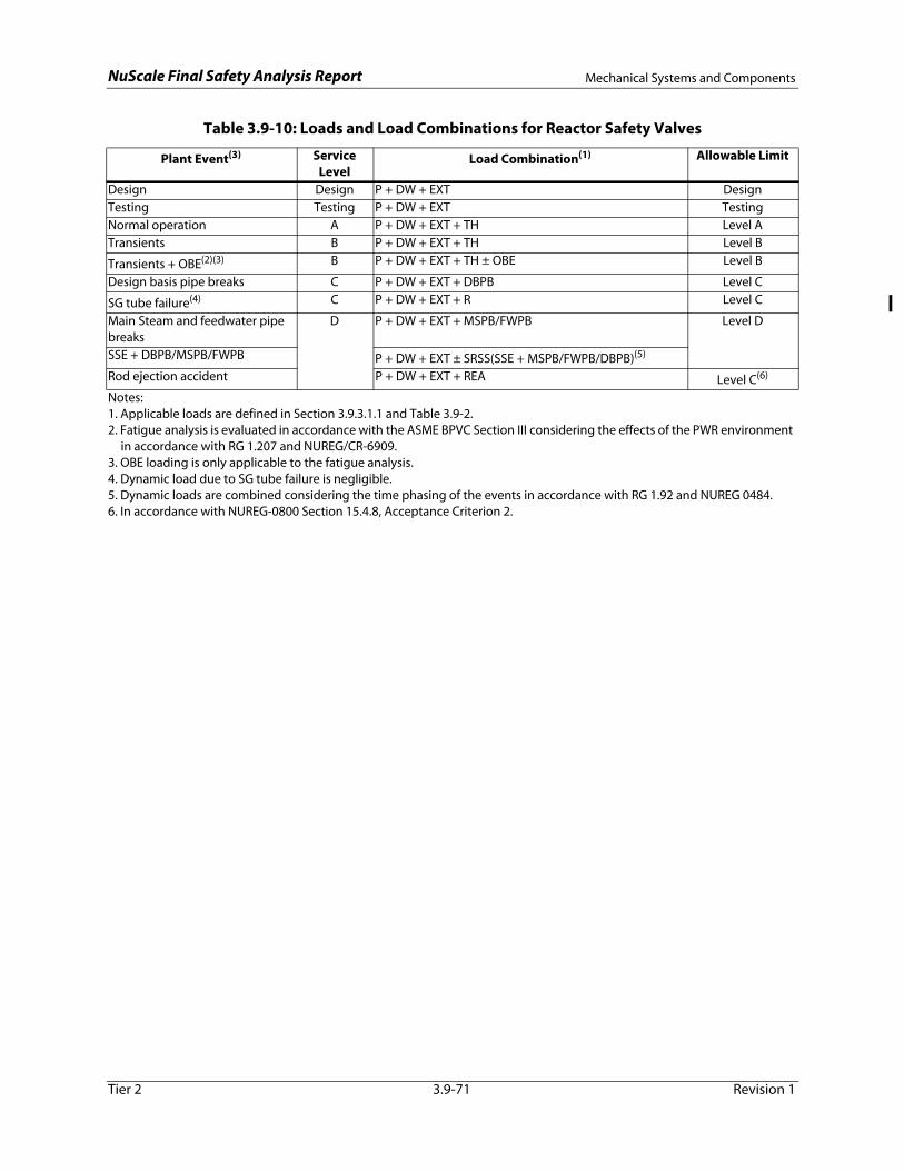
NuScale Final Safety Analysis Report Mechanical Systems and Components
Tier 2 3.9-71 Revision 1
Table 3.9-10: Loads and Load Combinations for Reactor Safety Valves
Plant Event(3) Service Level
Load Combination(1) Allowable Limit
Design Design P + DW + EXT DesignTesting Testing P + DW + EXT TestingNormal operation A P + DW + EXT + TH Level ATransients B P + DW + EXT + TH Level B
Transients + OBE(2)(3) B P + DW + EXT + TH ± OBE Level B
Design basis pipe breaks C P + DW + EXT + DBPB Level C
SG tube failure(4) C P + DW + EXT + R Level C
Main Steam and feedwater pipe breaks
D P + DW + EXT + MSPB/FWPB Level D
SSE + DBPB/MSPB/FWPB P + DW + EXT ± SRSS(SSE + MSPB/FWPB/DBPB)(5)
Rod ejection accident P + DW + EXT + REA Level C(6)
Notes:1. Applicable loads are defined in Section 3.9.3.1.1 and Table 3.9-2.2. Fatigue analysis is evaluated in accordance with the ASME BPVC Section III considering the effects of the PWR environment
in accordance with RG 1.207 and NUREG/CR-6909.3. OBE loading is only applicable to the fatigue analysis.4. Dynamic load due to SG tube failure is negligible.5. Dynamic loads are combined considering the time phasing of the events in accordance with RG 1.92 and NUREG 0484.6. In accordance with NUREG-0800 Section 15.4.8, Acceptance Criterion 2.

NuScale Final Safety Analysis Report Mechanical Systems and Components
Tier 2 3.9-72 Revision 1
Table 3.9-11: Load Combinations for Emergency Core Cooling System Valves
Plant Event Service Level Load Combination(1) Allowable Limit
Design Design P + DW + B + EXT DesignTesting Testing P + DW + B + EXT TestingNormal operation A P + DW + B + EXT + TH Level ATransients B P + DW + B + EXT + TH Level B
Transients + OBE(2)(3) B P + DW + B + EXT + TH ± OBE Level B
Design basis pipe breaks C P + DW + B + EXT + DBPB Level CHydrogen detonation C Pg1 + DW + B Level C
SG tube failure(4) C P + DW + B + EXT + R Level C
Rod ejection accident D P + DW + B + EXT + REA Level C(5)
Main steam and feedwater pipe breaks
D P + DW + B + EXT + MSPB/FWPB Level D
SSE + DBPB/MSPB/FWPB D P + DW + B + EXT ± SRSS(SSE + DBPB/MSPB/FWPB)(6)
Level D
Hydrogen DDT D Pg2 + DW + B Level D
Notes:1. Applicable loads are defined in Section 3.9.3.1.1 and Table 3.9-2.2. Fatigue analysis of all applicable components is evaluated in accordance with the applicable ASME Code considering the
effects of the PWR environment in accordance with RG 1.207.3. OBE is included in fatigue analyses.4. Dynamic load due to SG tube failure is negligible.5. In accordance with NUREG-0800 Section 15.4.8, Acceptance Criterion 2.6. Dynamic loads are combined considering the time phasing of the events in accordance with RG 1.92 and NUREG-0484.

NuScale Final Safety Analysis Report Mechanical Systems and Components
Tier 2 3.9-73 Revision 1
Table 3.9-12: Required Loads and Load Combinations for Secondary System Containment Isolation Valves
Plant Event Service Level Load Combination(1) Allowable Limit
Design Design P + DW + B + EXT + M DesignTesting Testing P + DW + B + EXT + M TestingNormal operation A P + DW + B + EXT + M + TH Level ATransients B P + DW + B + EXT + M + TH Level B
Transients + OBE(2)(3) B P + DW + B + EXT + M + TH ± OBE Level B
Design basis pipe breaks C P + DW + B + EXT + M + DBPB Level C
SG tube failure(4) C P + DW + B + EXT + M + R Level C
Main steam and feedwater pipe breaks
D P + DW + B + EXT + M + MSPB/FWPB Level D
Pipe Breaks + SSE D P + DW + B + EXT + M ± SRSS (SSE + MSPB/FWPB/DBPB)(5)
Level D
Rod ejection accident D P + DW + B + EXT + M + REA Level C(6)
Notes:1. Applicable loads are defined in Section 3.9.3.1.1 and Table 3.9-2.2. Fatigue analysis of all applicable components is evaluated in accordance with the applicable ASME Code.3. OBE is included in fatigue analyses.4. Dynamic load due to SG tube failure is negligible.5. Dynamic loads are combined considering the time phasing of the events in accordance with RG 1.92 and NUREG-0484.6. In accordance with NUREG-0800 Section 15.4.8, Acceptance Criterion 2.
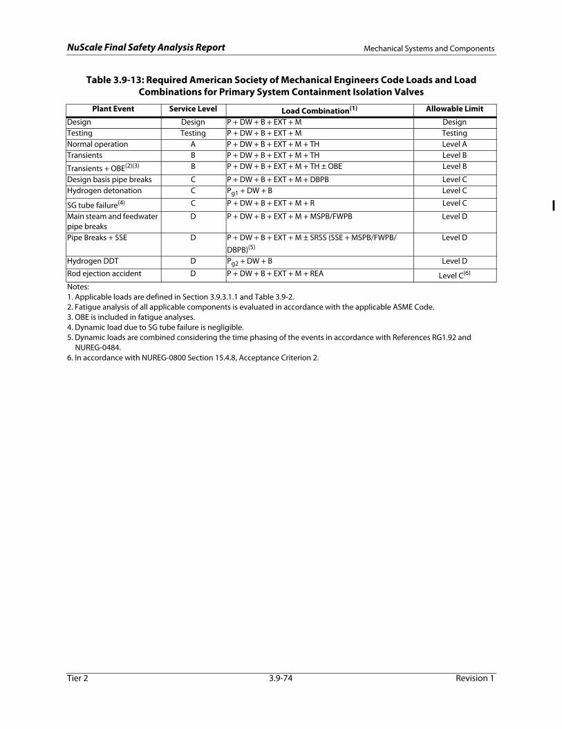
NuScale Final Safety Analysis Report Mechanical Systems and Components
Tier 2 3.9-74 Revision 1
Table 3.9-13: Required American Society of Mechanical Engineers Code Loads and Load Combinations for Primary System Containment Isolation Valves
Plant Event Service Level Load Combination(1) Allowable Limit
Design Design P + DW + B + EXT + M DesignTesting Testing P + DW + B + EXT + M TestingNormal operation A P + DW + B + EXT + M + TH Level ATransients B P + DW + B + EXT + M + TH Level B
Transients + OBE(2)(3) B P + DW + B + EXT + M + TH ± OBE Level B
Design basis pipe breaks C P + DW + B + EXT + M + DBPB Level CHydrogen detonation C Pg1 + DW + B Level C
SG tube failure(4) C P + DW + B + EXT + M + R Level C
Main steam and feedwater pipe breaks
D P + DW + B + EXT + M + MSPB/FWPB Level D
Pipe Breaks + SSE D P + DW + B + EXT + M ± SRSS (SSE + MSPB/FWPB/DBPB)(5)
Level D
Hydrogen DDT D Pg2 + DW + B Level D
Rod ejection accident D P + DW + B + EXT + M + REA Level C(6)
Notes:1. Applicable loads are defined in Section 3.9.3.1.1 and Table 3.9-2.2. Fatigue analysis of all applicable components is evaluated in accordance with the applicable ASME Code.3. OBE is included in fatigue analyses.4. Dynamic load due to SG tube failure is negligible.5. Dynamic loads are combined considering the time phasing of the events in accordance with References RG1.92 and
NUREG-0484.6. In accordance with NUREG-0800 Section 15.4.8, Acceptance Criterion 2.
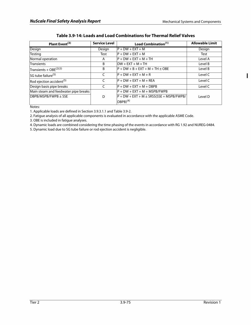
NuScale Final Safety Analysis Report Mechanical Systems and Components
Tier 2 3.9-75 Revision 1
Table 3.9-14: Loads and Load Combinations for Thermal Relief Valves
Plant Event(3) Service Level Load Combination(1) Allowable Limit
Design Design P + DW + EXT + M DesignTesting Test P + DW + EXT + M TestNormal operation A P + DW + EXT + M + TH Level ATransients B DW + EXT + M + TH Level B
Transients + OBE(2)(3) B P + DW + B + EXT + M + TH ± OBE Level B
SG tube failure(5) C P + DW + EXT + M + R Level C
Rod ejection accident(5) C P + DW + EXT + M + REA Level C
Design basis pipe breaks C P + DW + EXT + M + DBPB Level CMain steam and feedwater pipe breaks
DP + DW + EXT + M + MSPB/FWPB
Level DDBPB/MSPB/FWPB ± SSE P + DW + EXT + M ± SRSS(SSE + MSPB/FWPB/DBPB)(4)
Notes:1. Applicable loads are defined in Section 3.9.3.1.1 and Table 3.9-2.2. Fatigue analysis of all applicable components is evaluated in accordance with the applicable ASME Code.3. OBE is included in fatigue analyses.4. Dynamic loads are combined considering the time phasing of the events in accordance with RG 1.92 and NUREG-0484.5. Dynamic load due to SG tube failure or rod ejection accident is negligible.

NuScale Final Safety Analysis Report Mechanical Systems and Components
Tier 2 3.9-76 Revision 1
Table 3.9-15: Active Valve List
Valve No. Description ASME Class Function1
ASME Class 1, 2, and 3Chemical and Volume Control SystemCVC-AOV-0001 CVCS Discharge Isolation Valve 3 5CVC-CKV-0054 CVCS Injection Check Valve 3 5CVC-CKV-0057 Pressurizer Spray Check Valve 3 5CVC-SV-0079 RPV High Point Degasification Isolation Valve 3 5CVC-AOV-0101 Demineralized Water Supply Isolation Valve 3 3CVC-AOV-0119 Demineralized Water Supply Isolation Valve 3 3Containment SystemCVC-ISV-0323 Pressurizer Spray Outboard Containment Isolation Valve 1 1, 2, 3, 4CVC-ISV-0325 Pressurizer Spray Inboard Containment Isolation Valve 1 1, 2, 3, 4CVC-ISV-0329 Chemical and Volume Control System Injection Outboard
Containment Isolation Valve1 1, 2, 3, 4
CVC-ISV-0331 Chemical and Volume Control System Injection Inboard Containment Isolation Valve
1 1, 2, 3, 4
CVC-ISV-0334 Chemical and Volume Control System Discharge Inboard Containment Isolation Valve
1 1, 2, 3, 4
CVC-ISV-0336 Chemical and Volume Control System Discharge Outboard Containment Isolation Valve
1 1, 2, 3, 4
CVC-ISV-0401 RPV High Point Degasification Inboard Containment Isolation Valve 1 1, 2, 3, 4CVC-ISV-0403 RPV High Point Degasification Outboard Containment Isolation Valve 1 1, 2, 3, 4CE-ISV-0101 Containment Evacuation Inboard Containment Isolation Valve 2 2, 3, 4CE-ISV-0102 Containment Evacuation Outboard Containment Isolation Valve 2 2, 3, 4CFD-ISV-0129 Containment Flooding & Drain Outboard Containment Isolation
Valve2 2, 3, 4
CFD-ISV-0130 Containment Flooding & Drain Inboard Containment Isolation Valve 2 2, 3, 4RCCW-ISV-0184 Reactor Component Cooling Water Inlet Outboard Containment
Isolation Valve2 2, 3, 4
RCCW-ISV-0185 Reactor Component Cooling Water Inlet Inboard Containment Isolation Valve
2 2, 3, 4
RCCW-ISV-0190 Reactor Component Cooling Water Outlet Inboard Containment Isolation Valve
2 2, 3, 4
RCCW-ISV-0191 Reactor Component Cooling Water Outlet Outboard Containment Isolation Valve
2 2, 3, 4
FW-ISV-1003 Feedwater Isolation Valve 2 2, 3, 4FW-ISV-2003 Feedwater Isolation Valve 2 2, 3, 4FW-CKV-1002 Feedwater Isolation Check Valve 2 3FW-CKV-2002 Feedwater Isolation Check Valve 2 3MS-ISV-1005 Main Steam Isolation Valve 2 2, 3, 4MS-ISV-2005 Main Steam Isolation Valve 2 2, 3, 4MS-ISV-1006 Main Steam Isolation Bypass Valve 2 2, 3, 4MS-ISV-2006 Main Steam Isolation Bypass Valve 2 2, 3, 4Decay Heat Removal SystemDHR-HOV-1002A Decay Heat Removal System Actuation Valve 2 3, 4DHR-HOV-1002B Decay Heat Removal System Actuation Valve 2 3, 4DHR-HOV-2002A Decay Heat Removal System Actuation Valve 2 3, 4DHR-HOV-2002B Decay Heat Removal System Actuation Valve 2 3, 4
Emergency Core Cooling System2
ECC-HOV-0101A Reactor Vent Valve A 1 1, 3, 4ECC-HOV-0101B Reactor Vent Valve B 1 1, 3, 4

NuScale Final Safety Analysis Report Mechanical Systems and Components
Tier 2 3.9-77 Revision 1
ECC-HOV-0101C Reactor Vent Valve C 1 1, 3, 4ECC-HOV-0104A Reactor Recirculation Valve A 1 1, 3, 4ECC-HOV-0104B Reactor Recirculation Valve B 1 1, 3, 4
Safety and Relief ValvesRCS-PSV-0003A Reactor Safety Valve A 1 1, 3RCS-PSV-0003B Reactor Safety Valve B 1 1, 3SGS-PSV-1002 Steam Generator System Thermal Relief Valve 2 2SGS-PSV-2002 Steam Generator System Thermal Relief Valve 2 2
Non-Code Class ValvesCondensate and Feedwater System FW-FCV-1006 Feedwater Regulating Valve NC 6FW-FCV-2006 Feedwater Regulating Valve NC 6FW-CKV-1007 Backup Feedwater Check Valve NC 6FW-CKV-2007 Backup Feedwater Check Valve NC 6Main Steam SystemMS-AOV-1003 Backup Main Steam Isolation Valve NC 6MS-AOV-2003 Backup Main Steam Isolation Valve NC 6MS-AOV-1004 Backup Main Steam Isolation Bypass Valve NC 6MS-AOV-2004 Backup Main Steam Isolation Bypass Valve NC 61 - Function 1 - Reactor coolant pressure boundary
2 - Containment isolation3 - Accident mitigation4 - Safe shutdown5- Nonsafety related, but provide an augmented quality function6- Nonsafety backup to a safety-related function (Section 15.0.0.6.6)
2 - Trip and reset valves are included with each RVV and RRV.
Table 3.9-15: Active Valve List (Continued)
Valve No. Description ASME Class Function1

NuScale Final Safety A
nalysis ReportM
echanical Systems and Com
ponents
Tier 23.9-78
Revision 1
Table 3.9-16: Valve Inservice Test Requirements per ASME OM Code
Valve No. Description Valve /Actuator1
Position Augmented Function(s)2 ASME Class / IST
Category
IST Type and Frequency3 Valve Group4
Notes
Chemical and Volume Control SystemCVC-AOV-0101 Demineralized Water
Supply Isolation ValveBALL
Remote AOClosed Active
Boron Dilution PreventionClass 3
Category BPosition Verification Test/2 YearsExercise Full Stroke/QuarterlyFailsafe Test/Quarterly Operability Test
1 5, 16
CVC-AOV-0119 Demineralized Water Supply Isolation Valve
BALLRemote AO
Closed ActiveBoron Dilution Prevention
Class 3 Category B
Position Verification Test/2 YearsExercise Full Stroke/QuarterlyFailsafe Test/Quarterly Operability Test
1 5, 16
Containment SystemCVC-ISV-0323 Pressurizer Spray
Outboard Containment Isolation Valve
BALLRemote HO
Closed ActiveReactor Coolant Pressure BoundaryContainment Isolation
Class 1 Category A
Position Verification Test/2 YearsExercise Full Stroke/ QuarterlyFailsafe Test/ Quarterly Containment Isolation Leak TestOperability Test
2 6, 16
CVC-ISV-0325 Pressurizer Spray Inboard Containment Isolation Valve
BALLRemote HO
Closed ActiveReactor Coolant Pressure BoundaryContainment Isolation
Class 1 Category A
Position Verification Test/2 YearsExercise Full Stroke/ QuarterlyFailsafe Test/ QuarterlyContainment Isolation Leak TestOperability Test
2 6, 16
CVC-ISV-0329 Chemical and Volume Control System Injection Outboard Containment Isolation Valve
BALLRemote HO
Closed ActiveReactor Coolant Pressure BoundaryContainment Isolation
Class 1 Category A
Position Verification Test/2 YearsExercise Full Stroke/ QuarterlyFailsafe Test/Cold Shutdown Containment Isolation Leak TestOperability Test
2 6, 16
CVC-ISV-0331 Chemical and Volume Control System Injection Inboard Containment Isolation Valve
BALLRemote HO
Closed ActiveReactor Coolant Pressure BoundaryContainment Isolation
Class 1 Category A
Position Verification Test/2 YearsExercise Full Stroke/ QuarterlyFailsafe Test/ QuarterlyContainment Isolation Leak TestOperability Test
2 6, 16
CVC-ISV-0334 Chemical and Volume Control System Discharge Inboard Containment Isolation Valve
BALLRemote HO
Closed ActiveReactor Coolant Pressure BoundaryContainment Isolation
Class 1 Category A
Position Verification Test/2 YearsExercise Full Stroke/ QuarterlyFailsafe Test/Cold Shutdown Containment Isolation Leak TestOperability Test
2 6, 16

NuScale Final Safety A
nalysis ReportM
echanical Systems and Com
ponents
Tier 23.9-79
Revision 1
CVC-ISV-0336 Chemical and Volume Control System Discharge Outboard Containment Isolation Valve
BALLRemote HO
Closed ActiveReactor Coolant Pressure BoundaryContainment Isolation
Class 1 Category A
Position Verification Test/2 YearsExercise Full Stroke/ QuarterlyFailsafe Test/ QuarterlyContainment Isolation Leak TestOperability Test
2 6, 16
CVC-ISV-0401 RPV High Point Degasification Inboard Containment Isolation Valve
BALLRemote HO
Closed ActiveReactor Coolant Pressure BoundaryContainment Isolation
Class 1 Category A
Position Verification Test/2 YearsExercise Full Stroke/ QuarterlyFailsafe Test/ Quarterly Containment Isolation Leak TestOperability Test
2 6, 16
CVC-ISV-0403 RPV High Point Degasification Outboard Containment Isolation Valve
BALLRemote HO
Closed ActiveReactor Coolant Pressure BoundaryContainment Isolation
Class 1 Category A
Position Verification Test/2 YearsExercise Full Stroke/ QuarterlyFailsafe Test/ QuarterlyContainment Isolation Leak TestOperability Test
2 6, 16
CE-ISV-0101 Containment Evacuation Inboard Containment Isolation Valve
BALLRemote HO
Closed ActiveContainment Isolation
Class 2 Category A
Position Verification Test/2 YearsExercise Full Stroke/ QuarterlyFailsafe Test/Cold Shutdown Containment Isolation Leak TestOperability Test
2 6, 16
CE-ISV-0102 Containment Evacuation Outboard Containment Isolation Valve
BALLRemote HO
Closed ActiveContainment Isolation
Class 2 Category A
Position Verification Test/2 YearsExercise Full Stroke/ QuarterlyFailsafe Test/ QuarterlyContainment Isolation Leak TestOperability Test
2 6, 16
CFD-ISV-0129 Containment Flooding & Drain Outboard Containment Isolation Valve
BALLRemote HO
Closed ActiveContainment Isolation
Class 2 Category A
Position Verification Test/2 YearsExercise Full Stroke/ QuarterlyFailsafe Test/ QuarterlyContainment Isolation Leak TestOperability Test
2 6, 16
CFD-ISV-0130 Containment Flooding & Drain Inboard Containment Isolation Valve
BALLRemote HO
Closed ActiveContainment Isolation
Class 2 Category A
Position Verification Test/2 YearsExercise Full Stroke/ QuarterlyFailsafe Test/ QuarterlyContainment Isolation Leak TestOperability Test
2 6, 16
Table 3.9-16: Valve Inservice Test Requirements per ASME OM Code (Continued)
Valve No. Description Valve /Actuator1
Position Augmented Function(s)2 ASME Class / IST
Category
IST Type and Frequency3 Valve Group4
Notes

NuScale Final Safety A
nalysis ReportM
echanical Systems and Com
ponents
Tier 23.9-80
Revision 1
RCCW-ISV-0184 Reactor Component Cooling Water Inlet Outboard Containment Isolation Valve
BALLRemote HO
Closed ActiveContainment Isolation
Class 2 Category A
Position Verification Test/2 YearsExercise Full Stroke/Cold ShutdownFailsafe Test/Cold Shutdown Containment Isolation Leak TestOperability Test
2 6, 7, 16
RCCW-ISV-0185 Reactor Component Cooling Water Inlet Inboard Containment Isolation Valve
BALLRemote HO
Closed ActiveContainment Isolation
Class 2 Category A
Position Verification Test/2 YearsExercise Full Stroke/Cold ShutdownFailsafe Test/Cold Shutdown Containment Isolation Leak TestOperability Test
2 6, 7, 16
RCCW-ISV-0190 Reactor Component Cooling Water Outlet Inboard Containment Isolation Valve
BALLRemote HO
Closed ActiveContainment Isolation
Class 2 Category A
Position Verification Test/2 YearsExercise Full Stroke/Cold ShutdownFailsafe Test/Cold Shutdown Containment Isolation Leak TestOperability Test
2 6, 7, 16
RCCW-ISV-0191 Reactor Component Cooling Water Outlet Outboard Containment Isolation Valve
BALLRemote HO
Closed ActiveContainment Isolation
Class 2 Category A
Position Verification Test/2 YearsExercise Full Stroke/Cold ShutdownFailsafe Test/Cold Shutdown Containment Isolation Leak TestOperability Test
2 6, 7, 16
FW-ISV-1003 Feedwater Isolation Valve
BALLRemote HO
Closed ActiveFeedwater IsolationContainment IsolationDecay Heat Removal Boundary
Class 2 Category A
Position Verification Test/2 YearsExercise Full Stroke/Cold ShutdownFailsafe Test/Cold Shutdown Operability Leak TestOperability Test
3 8, 15, 16
FW-ISV-2003 Feedwater Isolation Valve
BALLRemote HO
Closed ActiveFeedwater IsolationContainment IsolationDecay Heat Removal Boundary
Class 2 Category A
Position Verification Test/2 YearsExercise Full Stroke/Cold ShutdownFailsafe Test/Cold Shutdown Operability Leak TestOperability Test
3 8, 15, 16
FW-CKV-1002 Feedwater Check Valve NOZZLE CHECK
Closed ActiveFeedwater IsolationDecay Heat Removal Boundary
Class 2 Category C
Check Exercise/ Refueling 5 9
Table 3.9-16: Valve Inservice Test Requirements per ASME OM Code (Continued)
Valve No. Description Valve /Actuator1
Position Augmented Function(s)2 ASME Class / IST
Category
IST Type and Frequency3 Valve Group4
Notes

NuScale Final Safety A
nalysis ReportM
echanical Systems and Com
ponents
Tier 23.9-81
Revision 1
FW-CKV-2002 Feedwater Check Valve NOZZLE CHECK
Closed ActiveFeedwater IsolationDecay Heat Removal Boundary
Class 2 Category C
Check Exercise/ Refueling 5 9
MS-ISV-1005 Main Steam Isolation Valve
BALLRemote HO
Closed ActiveSteam Line IsolationContainment IsolationDecay Heat Removal Boundary
Class 2 Category A
Position Verification Test/2 YearsExercise Full Stroke/Cold ShutdownFailsafe Test/Cold Shutdown Operability Leak TestOperability Test
3 10, 15, 16
MS-ISV-2005 Main Steam Isolation Valve
BALLRemote HO
Closed ActiveSteam Line IsolationContainment IsolationDecay Heat Removal Boundary
Class 2 Category A
Position Verification Test/2 YearsExercise Full Stroke/Cold ShutdownFailsafe Test/Cold Shutdown Operability Leak TestOperability Test
3 10, 15, 16
MS-ISV-1006 Main Steam Isolation Bypass Valve
BALLRemote HO
Closed ActiveSteam Line IsolationContainment IsolationDecay Heat Removal Boundary
Class 2 Category A
Position Verification Test/2 YearsExercise Full Stroke/Cold ShutdownFailsafe Test/Cold Shutdown Operability Leak TestOperability Test
2 10, 15, 16
MS-ISV-2006 Main Steam Isolation Bypass Valve
BALLRemote HO
Closed ActiveSteam Line IsolationContainment IsolationDecay Heat Removal Boundary
Class 2 Category A
Position Verification Test/2 YearsExercise Full Stroke/Cold ShutdownFailsafe Test/Cold Shutdown Operability Leak TestOperability Test
2 10, 15, 16
Decay Heat Removal SystemDHR-HOV-1002A Decay Heat Removal
System Actuation ValveBALL
Remote HOOpen Active
Decay Heat RemovalClass 2
Category BPosition Verification Test/2 YearsExercise Full Stroke/Cold ShutdownFailsafe Test/Cold ShutdownOperability Test
3 11, 16
DHR-HOV-1002B Decay Heat Removal System Actuation Valve
BALLRemote HO
Open ActiveDecay Heat Removal
Class 2 Category B
Position Verification Test/2 YearsExercise Full Stroke/Cold ShutdownFailsafe Test/Cold ShutdownOperability Test
3 11, 16
DHR-HOV-2002A Decay Heat Removal System Actuation Valve
BALLRemote HO
Open ActiveDecay Heat Removal
Class 2 Category B
Position Verification Test/2 YearsExercise Full Stroke/Cold ShutdownFailsafe Test/Cold ShutdownOperability Test
3 11, 16
Table 3.9-16: Valve Inservice Test Requirements per ASME OM Code (Continued)
Valve No. Description Valve /Actuator1
Position Augmented Function(s)2 ASME Class / IST
Category
IST Type and Frequency3 Valve Group4
Notes

NuScale Final Safety A
nalysis ReportM
echanical Systems and Com
ponents
Tier 23.9-82
Revision 1
DHR-HOV-2002B Decay Heat Removal System Actuation Valve
BALLRemote HO
Open ActiveDecay Heat Removal
Class 2 Category B
Position Verification Test/2 YearsExercise Full Stroke/Cold ShutdownFailsafe Test/Cold ShutdownOperability Test
3 11, 16
Emergency Core Cooling SystemECC-HOV-0101A Reactor Vent Valve A GLOBE
Remote HOOpen/Closed
ActiveCore Cooling Recirculation PathReactor Coolant Pressure BoundaryLTOP
Class 1 Category BC
Position Verification Test/2 YearsExercise Full Stroke/Cold ShutdownFailsafe Test/Cold ShutdownOperability Test
4 12, 16Vent
valves also perform the LTOP function.
ECC-HOV-0101B Reactor Vent Valve B GLOBERemote HO
Open/Closed
ActiveCore Cooling Recirculation PathReactor Coolant Pressure BoundaryLTOP
Class 1 Category BC
Position Verification Test/2 YearsExercise Full Stroke/Cold ShutdownFailsafe Test/Cold ShutdownOperability Test
4 12, 16
ECC-HOV-0101C Reactor Vent Valve C GLOBERemote HO
Open/Closed
ActiveCore Cooling Recirculation PathReactor Coolant Pressure BoundaryLTOP
Class 1 Category BC
Position Verification Test/2 YearsExercise Full Stroke/Cold ShutdownFailsafe Test/Cold ShutdownOperability Test
4 12, 16
ECC-HOV-0104A Reactor Recirculation Valve A
GLOBERemote HO
Open/Closed
ActiveCore Cooling Recirculation PathReactor Coolant Pressure Boundary
Class 1 Category BC
Position Verification Test/2 YearsExercise Full Stroke/Cold ShutdownFailsafe Test/Cold ShutdownOperability Test
4 12, 16
ECC-HOV-0104B Reactor Recirculation Valve B
GLOBERemote HO
Open/Closed
ActiveCore Cooling Recirculation PathReactor Coolant Pressure Boundary
Class 1 Category BC
Position Verification Test/2 YearsExercise Full Stroke/Cold ShutdownFailsafe Test/Cold ShutdownOperability Test
4 12, 16
Table 3.9-16: Valve Inservice Test Requirements per ASME OM Code (Continued)
Valve No. Description Valve /Actuator1
Position Augmented Function(s)2 ASME Class / IST
Category
IST Type and Frequency3 Valve Group4
Notes

NuScale Final Safety A
nalysis ReportM
echanical Systems and Com
ponents
Tier 23.9-83
Revision 1
Notes:1. AO air operated CIV containment isolation valve
CNV containment vessel CVCS chemical and volume control systemDHRS decay heat removal system DWS demineralized water systemECCS emergency core cooling system FCV feedwater check valveFWIV feedwater isolation valve FWRV feedwater regulating valveHO hydraulic operated LRWS liquid radioactive waste system LTOP low temperature overpressure protection MCR main control roomMPS module protection system MSIV main steam isolation valveMSIBV main steam isolation bypass valve NPM NuScale Power ModulePORV power operated relief valve PSCIV primary system CIVRCCW reactor component cooling water RPV reactor pressure vesselRRV reactor recirculation valve RVV reactor vent valve
Safety and Relief ValvesRCS-PSV-0003A Reactor Safety Valve A SAFETY
Pilot OperatedSelf Actuating
Open/Closed
Overpressure ProtectionReactor Coolant Pressure Boundary
Class 1 Category BC
Position Verification Test, 2 Years (alternated)Class 1 Safety Valve Test/5 Years and 20% in 2 Years
6 13
RCS-PSV-0003B Reactor Safety Valve B SAFETYPilot OperatedSelf Actuating
Open/Closed
Overpressure ProtectionReactor Coolant Pressure Boundary
Class 1 Category BC
Position Verification Test, 2 Years (alternated)Class 1 Safety Valve Test/5 Years and 20% in 2 Years
6 13
SGS-PSV-1002 Steam Generator System Thermal Relief Valve
PRESSURE RELIEF
Self Actuating
Open/Closed
Thermal Overpressure ProtectionSteam Generator System Pressure BoundaryContainment IsolationDecay Heat Removal Boundary
Class 2 Category AC
Class 2/3 Relief Valve Test/10 Years and 20% in 4 Years
7 14
SGS-PSV-2002 Steam Generator System Thermal Relief Valve
PRESSURE RELIEF
Self Actuating
Open/Closed
Thermal Overpressure ProtectionSteam Generator System Pressure BoundaryContainment IsolationDecay Heat Removal Boundary
Class 2 Category AC
Class 2/3 Relief Valve Test/10 Years and 20% in 4 Years
7 14
Table 3.9-16: Valve Inservice Test Requirements per ASME OM Code (Continued)
Valve No. Description Valve /Actuator1
Position Augmented Function(s)2 ASME Class / IST
Category
IST Type and Frequency3 Valve Group4
Notes

NuScale Final Safety A
nalysis ReportM
echanical Systems and Com
ponents
Tier 23.9-84
Revision 1
SG steam generator SSCIV secondary system CIV
2. The NuScale design does not use safety-related electric power to mitigate accidents or for the safe shutdown of the NuScale Power Module; therefore, all valves listed as having an active safety function have an active-to-failed function to transfer to its safe position on loss of motive power. Valves with an active function are tested by observing the operation of the actuator upon loss of valve actuating power.
3. Cold Shutdown Outage as defined in ISTA-2000 is Mode 3, safe shutdown, with all reactor coolant temperatures < 200 °F. The term “cold shutdown” is used throughout Section 3.9.6 for clarity with the OM Code requirements (Section 3.9.6.4.1).
4. Valve Groups: Valves are grouped as required by OM Mandatory Appendices I, II and IV. Pressure Relief Devices (Mandatory Appendix I) are grouped by valve type, valve function, and Code class. Check valves (Mandatory Appendix II) are grouped by valve type and valve size. POVs (Mandatory Appendix IV-OM-2017) are grouped by actuator type, obturator type, valve size, and safety significance.
5. CVCS Makeup and Module Isolation Valves (Section 9.3.4.2.2): These two safety-related, air operated valves are in series in the common DWS/LRWS makeup line to the CVCS makeup pumps. The valves close automatically on an MPS signal to mitigate an inadvertent boron dilution event.
6. Primary System Containment Isolation Valves (Section 6.2.4.2.2, Figure 6.2-5): PSCIVs are HO to open, nitrogen gas to close. These valves are located on nozzle penetrations on the CNV head and are intended to satisfy the requirements of GDC 55 and 56. All PSCIVs are designed with two valve actuators installed in a single valve body that is welded directly to the CNV nozzle safe-end. The valves close automatically on an MPS signal or loss of power to isolate containment and preserve RCS inventory. When the valve is deenergized, parallel hydraulic vent paths open, allowing fluid to vent from the valve actuator. This allows the nitrogen gas cylinder to overcome hydraulic pressure and to close the valve. The nitrogen cylinder is sealed and its pressure monitored by plant instrumentation, with alarms and indication available in the MCR. The exercise test and operability test (Note 16) shall determine the state of the nitrogen cylinder (pressure, temperature), the state of the obturator (stroke time, diagnostics), and the state of each hydraulic vent path (by testing each vent path individually). These valves have a test insert that allows 10 CFR 50 Appendix J, Type C testing locally in the direction of containment accident pressure.
7. The RCCW CIVs (Section 6.2.4.2.2) cannot be full stroked during normal operation because this will interrupt cooling flow the CRDMs. The CRDMs operate in the containment vacuum and depend on RCCW cooling for heat removal. Interrupting cooling flow to the CRDMs can cause overheating and lead to a possible rod drop.
8. Feedwater Isolation Valves (Section 6.2.4.2.2, Figure 6.2-6b): FWIVs are HO to open, nitrogen gas to close. These valves are located on two nozzle penetrations on the CNV head and are intended to satisfy the requirements of GDC 57. The FWIV is designed with the actuator installed inboard and a feedwater check valve installed outboard in the same valve body. The valve is welded directly to the CNV nozzle safe-end. The valves close automatically on a MPS signal or loss of power to isolate the feedwater line and preserve DHRS inventory. When the valve is deenergized, parallel hydraulic vent paths open, allowing fluid to vent from the valve actuator. This allows the nitrogen gas cylinder to overcome hydraulic pressure and close the valve. The nitrogen cylinder is sealed and its pressure monitored by plant instrumentation, with alarms and indication available in the MCR. The exercise test and operability test (Note 19) shall determine the state of the nitrogen cylinder (pressure, temperature), the state of the obturator (stroke time, diagnostics), and the state of each hydraulic vent path (by testing each vent path individually). These valves have a test insert that allows Technical
Mandatory Appendix Group No. Valve
IV 1 AOV, BALL, LSSIV 2 HOV [small actuator type], BALL, HSS (CVCS only) and LSSIV 3 HOV [large actuator type], BALL, LSSIV 4 PORV, Globe, HSSII 5 NOZZLE CHECK valve, 4-inch, normally closedI 6 Class 1 SAFETY valve I 7 Class 2 PRESSURE RELIEF valve

NuScale Final Safety A
nalysis ReportM
echanical Systems and Com
ponents
Tier 23.9-85
Revision 1
Specification leakage testing (Note 15) locally in the direction of DHRS pressure. These valves cannot be full-stroke or part stroke exercised during plant operation because closing the valves interrupts feedwater flow resulting in possible steam generator level transients and may initiate a turbine or NPM trip.
9. Feedwater Check Valves (Section 6.2.4.2.1, Figure 6.2-6b): The feedwater check valves are credited for rapidly acting to the safety function position (closed) to preserve DHRS inventory on a loss of feedwater. The FCVs are normally closed nozzle check valves. The FWIV is credited with providing the primary DHRS/feedwater boundary and has specific leakage criteria. The FCV maintains the DHRS boundary until the FWIV is fully closed and therefore, has no specific leakage criteria. The FCV is located in the same valve body as the FWIV and is located outboard of the two (FWIV located nearest the CNV). These valves cannot be full-stroke or part stroke exercised closed during plant operation because closing the valves interrupts feedwater flow resulting in possible steam generator level transients and may initiate a turbine or NPM trip. The FWIV/FCV body is equipped with a test insert that allows leakage testing following system shutdown. The closed exercised test will be performed at cold shutdown with a leak test to verify the valve is fully closed. Normal feedwater operation will satisfy the open exercise (nonsafety direction) for these valves pursuant to ISTC-3550, Valves in Regular Use, at a frequency that satisfies requirements of the OM Code by periodically measuring FW flow to confirm the valve obturator is fully open.
10. Main Steam Isolation Valves and Bypass (Section 6.2.4.2.2, Figure 6.2-6a): MSIVs and MSIBVs are HO to open, nitrogen gas to close. These valves located on the two main steam nozzle penetrations on the CNV head and are intended to satisfy the requirements of GDC 57. One actuator is located in a single valve body that is welded to a ASME Class 2 pipe. The valves close automatically on a MPS signal or loss of power to isolate the main stream line and preserve DHRS inventory (the MSIBV is normally closed). When the valve is deenergized, parallel hydraulic vent paths open allowing fluid to vent from the valve actuator. This allows the nitrogen gas cylinder to overcome hydraulic pressure and close the valve. The nitrogen cylinder is sealed and its pressure monitored by plant instrumentation, with alarms and indication available in the MCR. The exercise test and operability test (Note 16) shall determine the state of the nitrogen cylinder (pressure, temperature), the state of the obturator (stroke time, diagnostics), and the state of each hydraulic vent path (by testing each vent path individually). These valves have a test insert that allows leakage testing (Note 15) locally in the direction of steam flow and DHRS isolation. These valves cannot be full-stroke or part stroke exercised during plant operation because closing the valves interrupts steam flow resulting in possible steam generator pressure and level transients and may initiate a turbine or NPM trip.
11. Decay Heat Removal System Actuation Valves (Section 5.4.3.2.1): DHRS actuation valves are HO to close, nitrogen gas to open. These valves are located on two closed loops outside the CNV and are intended to satisfy the requirements of GDC 57. There are two valves in parallel in each loop, four valves total. Either valve is designed to fulfill the system safety function requirement. The valves open automatically on a MPS signal or loss of power to initiate decay heat removal circulation through the DHRS condenser and corresponding SG. When the valve is deenergized, parallel hydraulic vent paths open allowing fluid to vent from the valve actuator. This allows the nitrogen gas cylinder to overcome hydraulic pressure and open the valve. The nitrogen cylinder is sealed and its pressure monitored by plant instrumentation, with alarms and indication available in the MCR. The exercise test and operability test (Note 16) shall determine the state of the nitrogen cylinder (pressure, temperature), the state of the obturator (stroke time, diagnostics), and the state of each hydraulic vent path (by testing each vent path individually). These valves cannot be full-stroke or part stroke exercised during plant operation because opening the valves would unnecessarily subject the SG nozzles to thermal transients from the decay heat condenser condensate flow.
12. Emergency Core Cooling Valves (Section 6.3.2.2, Figure 6.3-3): The ECCS RRVs and RVVs are PORVs that each consist of a main valve, a trip pilot, a reset pilot and an inadvertent actuation block. These components are considered as one valve assembly and are exercised tested as a unit during cold shutdown. However, operability testing per Note 16 may be performed separately to provide additional diagnostic information to assess valve performance. These valves cannot be full or partial stroke exercised during plant operation because cycling a valve opens an RCS vent path resulting in a potential loss of core cooling. The active safety function of the valves is to open and remain open when actuated. The closed safety function to support the reactor coolant pressure boundary is passive. The reset pilot is a nonsafety function and is not inservice tested as part of the ASME OM Code IST program. The trip valve is tested during failsafe and exercise testing.
RRVs and RVVs do not have specific leakage criteria. Seat tightness will be in accord with the requirements of the OM Code Mandatory Appendix I. ECCS valve seat leakage will be RCS unidentified leakage and must meet Technical Specification surveillance criteria. The owner's seat tightness criteria should be in accordance with the methods prescribed in OM Mandatory Appendix I, Table I-8220-1. The associated pilot valve bodies form part of the reactor coolant and containment boundaries and are subject to 10 CFR 50 Appendix J Type B testing.

NuScale Final Safety A
nalysis ReportM
echanical Systems and Com
ponents
Tier 23.9-86
Revision 1
ISTC-5110 Power Operated Relief Valves - RRVs and RVVs have attributes of both power operated valves (ISTC-5100) and relief valves (ISTC-5240). Operability testing per Note 16 includes a functional test of the inadvertent actuation block at normal RCS pressure to confirm that the ECCS valve does not open. Testing also includes an operational test to demonstrate that the valves not exercise tested will open on low RCS pressure even though the trip valves remain energized (closed).
13. Reactor Safety Valves (Section 5.1.3.5): These valves are not exercised for inservice testing; their position indication components are tested by local inspection without valve exercise. RSVs do not have specific leakage criteria. Seat tightness will be in accord with the requirements of the OM Code Mandatory Appendix I. Any RSV seat leakage will be RCS unidentified leakage and must meet Technical Specification surveillance criteria. Owner's as-left seat tightness criteria shall be no observed leakage utilizing the methods prescribed in OM Mandatory Appendix I, Table I-8220-1.
14. Steam Generator System Thermal Relief Valves (Section 5.4.1.2): These thermal relief valves are located inside containment on each SG system feedwater header.
15. All secondary systems containment isolation valves close to complete the decay heat removal system boundary. All of these valves have specific leakage criteria and are tested per NuScale Technical Specification surveillance test (Technical Specification SR 3.7.1.2 and SR 3.7.2.2).
16. These valves are subject to operability testing per the requirements of 10 CFR 50.55a. The test frequencies are to be established in accordance with the intent ASME OM Code - 2017, Mandatory Appendix IV. The approach detailed in Mandatory Appendix IV shall be applied to both AOVs and HOVs.
OM Mandatory Appendix IV and this Plan address the attributes of a successful POV program as delineated in NRC Regulatory Issue Summary (RIS) 2000-3, "Resolution of Generic Safety Issue 158: Performance of Safety-Related Power Operated Valves Under Design Basis Conditions." See subsection 3.9.6.2.2 (3) for the factors to be considered in the evaluation of operability testing.

NuScale Final Safety A
nalysis ReportM
echanical Systems and Com
ponents
Tier 23.9-87
Revision 1
Table 3.9-17: Valve Augmented Requirements
Valve No. Description Valve /Actuator1
Position AugmentedFunction(s)2
IST Category
IST Type3 Notes
Chemical Volume and Control SystemCVC-AOV-0339 CVCS Discharge Isolation
ValveGLOBE
Remote AOClosed Active
Containment IsolationCategory A Position Verification Test
Exercise Full Stroke Failsafe TestOperability Leak Test
9
CVC-CKV-0353 CVCS Injection Check Valve
NOZZLE CHECK Closed ActiveContainment Isolation
Category A/C Check Exercise/ Refueling 8, 9
CVC-CKV-0352 Pressurizer Spray Check Valve
NOZZLE CHECK Closed ActiveContainment Isolation
Category A/C Check Exercise/ Refueling 8, 9
CVC-AOV-0406 RPV High Point Degasification Isolation Valve
GLOBERemote AO
Closed ActiveContainment Isolation
Category A Position Verification TestExercise Full StrokeFailsafe TestOperability Leak Test
9
Condensate and Feedwater SystemFW-FCV-1006 Feedwater Regulating
ValveFCV
Remote AOClosed Active
Feedwater IsolationContainment IsolationDecay Heat Removal Boundary
Category A Position Verification TestExercise Full Stroke/Cold ShutdownFailsafe Test/Cold Shutdown Operability Leak Test
4, 7
FW-FCV-2006 Feedwater Regulating Valve
FCVRemote AO
Closed ActiveFeedwater IsolationContainment IsolationDecay Heat Removal Boundary
Category A Position Verification TestExercise Full Stroke/Cold ShutdownFailsafe Test/Cold Shutdown Operability Leak Test
4, 7
FW-CKV-1007 Backup Feedwater Check Valve
Nozzle Check Closed ActiveDecay Heat Removal Boundary
Category C Check Exercise/ Refueling 5
FW-CKV-2007 Backup Feedwater Check Valve
Nozzle Check Closed ActiveDecay Heat Removal Boundary
Category C Check Exercise/ Refueling 5
Main Steam SystemMS-AOV-1003 Backup Main Steam
Isolation ValveGATE
Remote AOClosed Active
Steam Line IsolationContainment IsolationDecay Heat Removal Boundary
Category A Position Verification TestExercise Full Stroke/Cold ShutdownFailsafe Test/Cold Shutdown Operability Leak Test
6,7

NuScale Final Safety A
nalysis ReportM
echanical Systems and Com
ponents
Tier 23.9-88
Revision 1
Notes:
2. Valves with augmented test requirements either provide a nonsafety backup to a safety-related function or are nonsafety-related that provide an augmented quality function. The NuScale design does not use safety-related electric power to mitigate accidents or for the safe shutdown of the NuScale Power Module; therefore, all valves listed have an active-to-failed function to transfer to its backup position on loss of motive power. Valves with an active function are tested by observing the operation of the actuator upon loss of valve actuating power.
3. Cold Shutdown Outage as defined in ASME OM-2017 ISTA-2000 is Mode 3, safe shutdown, with all reactor coolant temperatures < 200 °F. The term "cold shutdown" is used throughout Section 3.9.6 for clarity with the OM Code requirements (Section 3.9.6.4.1).
4. Feedwater Regulating Valves (Section 10.4.7.2.2): The FWRVs are nonsafety-related, not risk-significant backup isolation valves to the safety-related FWIVs and are credited in safety analysis. These valves have the same design pressure and temperature as the RCS. These valves cannot be full-stroke or part-stroke exercised during plant operation because closing the valves interrupts feedwater flow, resulting in possible steam generator level transients, and may initiate a turbine or NPM trip.
5. Backup Feedwater Check Valves (Section 10.4.7.2.2): The backup feedwater check valves are nonsafety-related, not risk-significant backup check valves to the safety- related FCV and are credited in safety analysis. These valves are credited for rapid acting to the safety function position (closed) to preserve DHRS inventory on a loss of feedwater. The backup FCVs are normally closed, nozzle check valves. The FWRV is credited with providing the backup DHRS/feedwater boundary and has specific leakage criteria. The backup FCV maintains the DHRS boundary until the FWRV is fully closed and, therefore, has no specific leakage criteria. These valves cannot be full- stroke or part-stroke exercised closed during plant operation because closing the valves interrupts feedwater flow, resulting in possible steam generator level transients,
MS-AOV-2003 Backup Main Steam Isolation Valve
GATERemote AO
Closed ActiveSteam Line IsolationContainment IsolationDecay Heat Removal Boundary
Category A Position Verification TestExercise Full Stroke/Cold ShutdownFailsafe Test/Cold Shutdown Operability Leak Test
6,7
MS-AOV-1004 Backup Main Steam Isolation Bypass Valve
GATERemote AO
Closed ActiveSteam Line IsolationContainment IsolationDecay Heat Removal Boundary
Category A Position Verification TestExercise Full Stroke/Cold ShutdownFailsafe Test/Cold Shutdown Operability Leak Test
6,7
MS-AOV-2004 Backup Main Steam Isolation Bypass Valve
GATERemote AO
Closed ActiveSteam Line IsolationContainment IsolationDecay Heat Removal Boundary
Category A Position Verification TestExercise Full Stroke/Cold ShutdownFailsafe Test/Cold Shutdown Operability Leak Test
6,7
1. AO air operated DHRS decay heat removal systemFCV feedwater check valve FWIV feedwater isolation valveFWRV feedwater regulating valve MSIV main steam isolation valveMSIBV main steam isolation bypass valve NPM NuScale Power ModuleCVCS chemical volume and control RPV reactor pressure vessel
Table 3.9-17: Valve Augmented Requirements (Continued)
Valve No. Description Valve /Actuator1
Position AugmentedFunction(s)2
IST Category
IST Type3 Notes

NuScale Final Safety A
nalysis ReportM
echanical Systems and Com
ponents
Tier 23.9-89
Revision 1
and may initiate a turbine or NPM trip. The nozzle check design is a spring-to-close design. Nonintrusive testing can be used to verify valve closure during plant shutdown or during cold shutdown. Normal feedwater operation satisfies the open exercise (nonsafety direction) for these valves pursuant to ISTC-3550, Valves in Regular Use, at a frequency that satisfies requirements of the OM Code by periodically measuring FW flow and pressure to confirm the valves are fully open.
6. Backup Main Steam Isolation Valves and Bypass (Section 10.3.2.2): The backup MSIVs and MSIBVs are nonsafety-related, not risk significant backup isolation valves to the safety-related MSIVs and MSIBVs and are credited in safety analysis. These valves have the same design pressure and temperature as the RCS. These valves cannot be full- stroke or part stroke exercised during plant operation because closing the valves would interrupt steam flow resulting in possible steam generator pressure and level transients and may initiate a turbine or NPM trip.
7. All secondary systems containment backup isolation valves close to complete the decay heat removal system boundary. All of these valves have specific leakage criteria and are tested per NuScale Technical Specification surveillance test (Technical Specification SR 3.7.1.2 and SR 3.7.2.2).
8. Backup CVCS Check Valves: The backup CVCS check valves are normally closed, nozzle check valves. These valves cannot be full- stroke or part-stroke exercised closed during plant operation because system flow must be reversed to demonstrate valve closure. The nozzle check design is a spring-to-close design. Nonintrusive testing can be used to verify valve closure during plant shutdown. Normal CVCS operation satisfies the open exercise for these valves pursuant to ISTC-3550, Valves in Regular Use, at a frequency that satisfies the owner's requirements for augmented testing by periodically measuring line flow and pressure to confirm the valves are fully open.
9. Backup Containment Isolation Valves: Third isolation valves that provide a nonsafety backup function as defined by Regulatory Guide 1.26 Revision 4, C.2(c) footnote 6 as having “high leaktight integrity.” These valves define the NRC Quality Group C/D and Seismic I/III classification break. The power operated valves receive a nonsafety containment isolation signal.

NuScale Final Safety A
nalysis ReportM
echanical Systems and Com
ponents
Tier 23.9-90
Revision 1
Table 3.9-18: Not Used

NuScale Final Safety A
nalysis ReportM
echanical Systems and Com
ponents
Tier 23.9-91
Revision 1
Table 3.9-19: Not Used

NuScale Final Safety A
nalysis ReportM
echanical Systems and Com
ponents
Tier 23.9-92
Revision 1
Table 3.9-20: Not Used

NuScale Final Safety A
nalysis ReportM
echanical Systems and Com
ponents
Tier 23.9-93
Revision 1
Table 3.9-21: Not Used

NuScale Final Safety A
nalysis ReportM
echanical Systems and Com
ponents
Tier 23.9-94
Revision 1
Table 3.9-22: Not Used

NuScale Final Safety A
nalysis ReportM
echanical Systems and Com
ponents
Tier 23.9-95
Revision 1
Table 3.9-23: Not Used

NuScale Final Safety A
nalysis ReportM
echanical Systems and Com
ponents
Tier 23.9-96
Revision 1
Table 3.9-24: Not Used

NuScale Final Safety A
nalysis ReportM
echanical Systems and Com
ponents
Tier 23.9-97
Revision 1
Table 3.9-25: Not Used

NuScale Final Safety A
nalysis ReportM
echanical Systems and Com
ponents
Tier 23.9-98
Revision 1
Table 3.9-26: Not Used

NuScale Final Safety Analysis Report Mechanical Systems and Components
Tier 2 3.9-99 Revision 1
Figure 3.9-1: Nuscale Power Module Showing Reactor Vessel Internals Component Assemblies
CNV
TYPICAL PRESSURIZER SPRAY NOZZLE
TYPICAL CONTROL ROD DRIVE (CRD) SHAFTTYPICAL ICI GUIDE TUBE
RPV
UPPER RISER ASSEMBLY
LOWER RISER ASSEMBLY
CORE SUPPORT ASSEMBLY
FLOW DIVERTER

NuScale Final Safety Analysis Report Mechanical Systems and Components
Tier 2 3.9-100 Revision 1
Figure 3.9-2: Upper Riser Assembly
A
A A A
CVCS INJECTION LINE
CRD SHAFT SUPPORT
CONTROL ROD DRIVE (CRD) SHAFT
ICI GUIDE TUBE
RPV(REF)
BELLOWS
CRD SHAFT SUPPORT
PRESSURIZER BAFFLE PLATE
CRD SHAFT SUPPORT
CRD SHAFT SUPPORT
CRD SHAFTSUPPORT

NuScale Final Safety Analysis Report Mechanical Systems and Components
Tier 2 3.9-101 Revision 1
Figure 3.9-3: Lower Riser Assembly
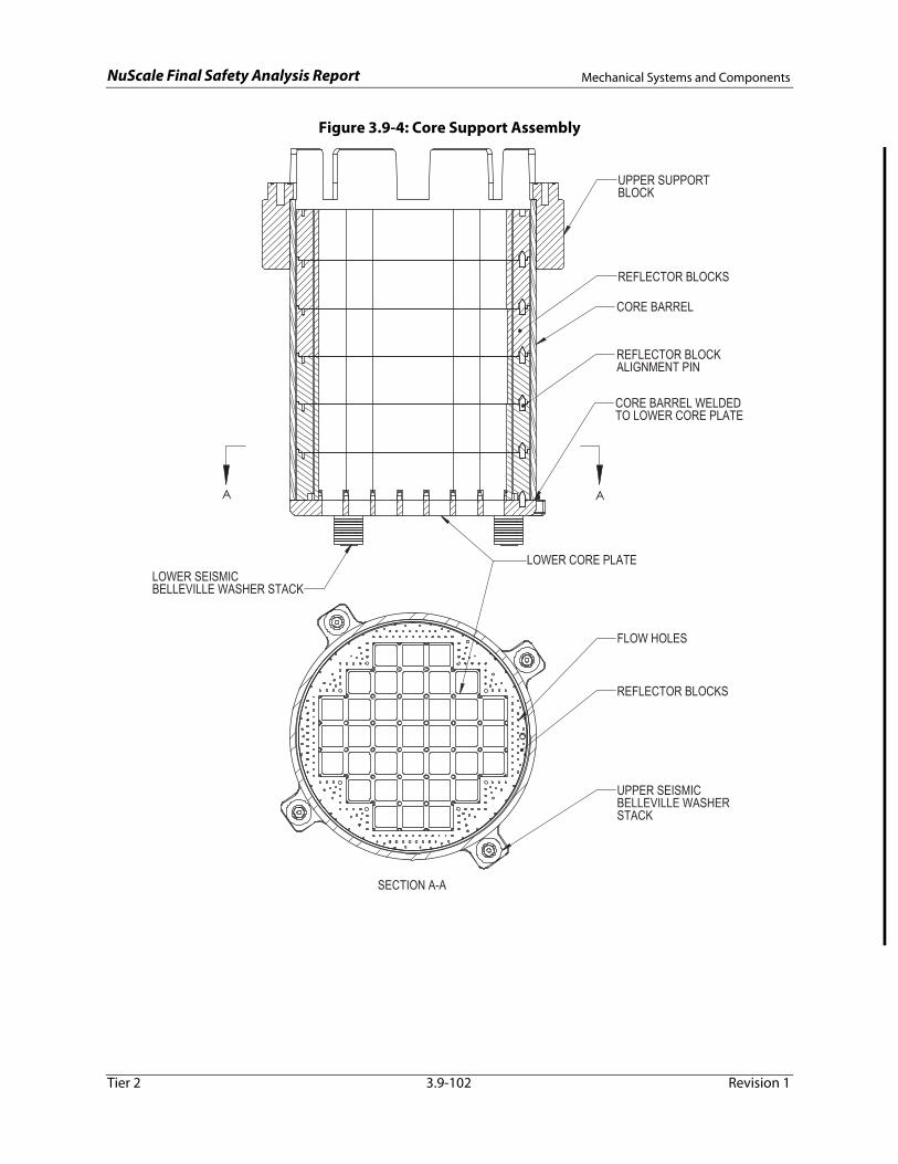
NuScale Final Safety Analysis Report Mechanical Systems and Components
Tier 2 3.9-102 Revision 1
Figure 3.9-4: Core Support Assembly
LOWER CORE PLATE
SECTION A-A
REFLECTOR BLOCKS
FLOW HOLES
UPPER SEISMICBELLEVILLE WASHER STACK
UPPER SUPPORTBLOCK
REFLECTOR BLOCKS
CORE BARREL
ALIGNMENT PINREFLECTOR BLOCK
CORE BARREL WELDEDTO LOWER CORE PLATE
AA
LOWER SEISMICBELLEVILLE WASHER STACK
NuScale Final Safety Analysis ReportSeismic and Dynamic Qualifications of Mechanical and Electrical
Equipment
Tier 2 3.10-1 Revision 1
3.10 Seismic and Dynamic Qualifications of Mechanical and Electrical Equipment
Electrical and mechanical equipment including instrumentation (with exception of piping) and their associated supports classified as Seismic Category I, are demonstrated through qualification to withstand the full range of normal and accident loadings. The equipment to be seismically and dynamically qualified includes the following:
• electrical equipment, including instrumentation and some post-accident monitoring equipment
• active, safety-related mechanical equipment, such as control rod drive mechanisms and some valves, that perform a mechanical motion to accomplish their safety function and other nonactive mechanical components, the structural integrity of which is maintained to perform their safety function
Seismic Category II structures, systems, and components are designed so that the safe shutdown earthquake (SSE) does not cause unacceptable structural failure of or interaction with Seismic Category I items.
The equipment to be qualified includes equipment necessary for safe shutdown, emergency core cooling, containment heat removal, containment isolation, or for mitigating the consequences of accidents or preventing a significant release of radioactive material to the environment. Also included is equipment in the reactor protection system, the engineered safety features, and highly reliable electrical equipment.
The structures, systems, and components qualified as Seismic Category I or Category II are listed in Table 3.2-1. Seismic qualification of the containment vessel, reactor pressure vessel, upper reactor vessel internals, lower reactor vessel internals and reactor core, and control rod drive mechanisms is addressed in Appendix 3A. Seismic design and analysis of the Seismic Category I buildings are addressed in Section 3.7 and Section 3.8. Seismic qualification of the Reactor Building crane and the bioshield are addressed in Section 3.7.3, and seismic qualification of the spent and new fuel racks is addressed in Section 9.1.
The information presented or referenced in this section includes the following:
• identification of the Seismic Category I equipment and supports
• criteria used for seismic qualification of the various types of equipment
• list of the safety-related functional requirements of equipment to be qualified
• definition of the seismic load inputs
• definition of other relevant dynamic load inputs and load combinations
• documentation of the qualification process
This section demonstrates that subject equipment conforms to the requirements of General Design Criteria 1, 2, 4, 14, and 30 as well as Appendix B and Appendix S to 10 CFR 50.
COL Item 3.10-1: A COL applicant that references the NuScale Power Plant design certification will develop and maintain a site-specific seismic and dynamic qualification program.

NuScale Final Safety Analysis ReportSeismic and Dynamic Qualifications of Mechanical and Electrical
Equipment
Tier 2 3.10-2 Revision 1
3.10.1 Seismic Qualification Criteria
3.10.1.1 Qualification Standards
The methodologies for seismic and dynamic qualification of mechanical and electrical equipment are described in Section 3.10.2. These methods are in compliance with the requirements of General Design Criteria 1, 2, 4, 14, 30, and 10 CFR 50 Appendix S. The methods used to implement the requirements of 10 CFR 50, Appendix B are described in Chapter 17.
The NuScale Power Plant implements the requirements of the IEEE 344-2004 standard (Reference 3.10-1) endorsed by RG 1.100 Revision 3. Seismic Category I pressure boundary components are designed in accordance with the requirements of Section III of the American Society of Mechanical Engineers Boiler and Pressure Vessel Code (Reference 3.10-2) to ensure their structural integrity. Other Seismic Category I equipment is qualified in accordance with IEEE 344-2004.
Qualification by analysis is performed when any of the following conditions are met:
• The only safety-related function of the equipment is to maintain its structural integrity.
• The equipment is too large to test at existing test facilities.
• The interfaces, such as interconnecting cables in a cable cabinet, cannot be regarded as conservatively modeled during testing because of the complexity of the linkage to the equipment subject to testing.
• The equipment has a linear or very simple nonlinear response that can be conservatively calculated by analysis.
The methods and requirements of ASME QME-1-2007 (Reference 3.10-3) as described in RG 1.100 are also used for the seismic qualification of active mechanical equipment.
The qualification of the electrical and mechanical equipment is based on the certified seismic design response spectra and the certified seismic design response spectra - high frequency defined in Section 3.7.1. The certified seismic design response spectra (including the certified seismic design response spectra - high frequency) is the site-independent SSE.
The operating basis earthquake (OBE) is defined as one third of the SSE. Therefore an explicit analysis or design is not required per Appendix S of 10 CFR 50. As a result, the low-level seismic effects (fatigue) required by Institute of Electrical and Electronics Engineers (IEEE) 344-2004 (Reference 3.10-1) to qualify electrical and mechanical equipment are considered using two SSE events, with 10 maximum stress-cycles each, for a total of 20 full cycles. This is considered equivalent to the cyclic load basis of one SSE and five OBEs. The determination of number of earthquake cycles is outlined in Section 3.7.3.
The equipment qualification program is described in Section 3.11. The methodology for seismic analysis of systems is provided in Section 3.7.3. A list of safety-related active valves, in accordance with the guidance of RG 1.100, is provided in Section 3.9.6.

NuScale Final Safety Analysis ReportSeismic and Dynamic Qualifications of Mechanical and Electrical
Equipment
Tier 2 3.10-3 Revision 1
3.10.1.2 Performance Requirements for Seismic Qualification
An equipment qualification record file (EQRF) is developed for each piece of electrical equipment and instrumentation classified as Seismic Category I. Section 3.11 and Appendix 3C provide the environmental conditions of the mechanical and electrical equipment, including the environmental conditions associated with normal operations, maintenance, testing, and postulated accidents, including seismic events. The performance requirements for the electrical equipment and instrumentation are defined in the EQRF. The test response spectrum (TRS) and required response spectrum (RRS) for the seismic qualification are also identified in the EQRF. The RRS is bounded by the TRS to demonstrate the conservative qualification of equipment.
For Seismic Category I active mechanical equipment, the performance requirements are defined in the corresponding equipment requirements specification. Requirements for active valves are addressed in EQRFs. Non-active Seismic Category I mechanical equipment have a single performance requirement - to maintain their structural integrity.
3.10.1.3 Performance Criteria
The qualification of Seismic Category I mechanical and electrical equipment demonstrates that the equipment is capable of performing its safety-related function under applicable plant loading conditions, including the SSE as defined in Section 3.7.1, in concert with other concurrent loadings.
3.10.2 Methods and Procedures for Qualifying Mechanical and Electrical Equipment and Instrumentation
The guidance and requirements of RG 1.100 Revision 3 and IEEE 344-2004 (Reference 3.10-1) are the source of the methods and procedures used for seismic and dynamic qualification of mechanical and electrical equipment. ASME QME-1-2007 (Reference 3.10-3) is used with the exceptions noted in RG 1.100 Revision 3 for the qualification of active mechanical equipment.
The Seismic Category I equipment is qualified to withstand the SSE in combination with other relevant static and dynamic loads with no adverse impacts to the safety functions. The acceptable load combinations for mechanical equipment are defined in Section 3.9.3.
Seismic Category I instrumentation and electrical equipment are qualified by type testing or by a combination of testing and analysis. The choice of qualification method is a function of factors such as expense, viability, equipment complexity, and previous seismic qualification test data. The qualification method for a particular instrument or piece of electrical equipment is identified in the EQRF.
The structural integrity and operability of active valves and dampers is qualified by a combination of analyses and tests. Other mechanical components are qualified by analysis.

NuScale Final Safety Analysis ReportSeismic and Dynamic Qualifications of Mechanical and Electrical
Equipment
Tier 2 3.10-4 Revision 1
3.10.2.1 Qualification by Testing
Seismic qualification of mechanical and electrical equipment by testing is performed in accordance with the requirements of IEEE 344-2004 (Reference 3.10-1). For equipment qualified by testing, the test simulates normal loadings, such as thermal and flow-induced loads, concurrently with the seismic and other dynamic loadings. The loads include forces imposed by piping onto the equipment. The survival and operability of the equipment is verified during and after the testing.
The seismic testing consists of subjecting the equipment to vibratory motion that simulates the vibratory motion postulated to occur at the equipment mounting location. The testing conservatively considers the multi-dimensional effects of the postulated earthquake.
Single-frequency and multi-frequency tests are used for seismic qualification. The in-structure floor response spectra damping values provide the seismic and dynamic test inputs. The purpose of multi-frequency testing is to provide a broadband test motion that can produce a simultaneous response from multiple modes of a multi-degree-of-freedom system, the malfunction of which can be caused by modal interactions. It is preferable to perform multi-frequency testing rather than single-frequency testing because of the usually broad frequency content of the seismic and dynamic load excitation.
However, single-frequency testing, such as sine beats, may be used in the following situations:
• when seismic ground motion is filtered due to a single predominant structural mode
• when it can be shown that the anticipated response of the equipment is sufficiently represented by a single mode
• when the input has enough duration and intensity to cause the excitation of the applicable modes to the required magnitude, causing the TRS to bound the corresponding spectra
• when the resultant floor motion consists of a single predominant frequency
For the seismic and dynamic portion of the loads, the test input motion should be applied to one vertical axis and one principal horizontal axis (or two orthogonal horizontal axes) simultaneously, unless it can be demonstrated that the equipment response in the vertical direction is not sensitive to the vibratory motion in the horizontal direction, and vice versa. The time phasing of the inputs in the vertical and horizontal directions must be such that a purely rectilinear resultant input is avoided. An acceptable alternative is to test with vertical and horizontal inputs in-phase, and then repeat the test with inputs 180 degrees out-of-phase. In addition, the test must be repeated with the equipment rotated 90 degrees horizontally.
The equipment mounting in the test setup simulates the equipment mounting in service and does not cause nonrepresentative dynamic coupling of the equipment to its mounting fixture. The test simulates the dynamic coupling effects of cable, conduit, instrument lines, electrical connects, and other interfaces, unless adequate justification

NuScale Final Safety Analysis ReportSeismic and Dynamic Qualifications of Mechanical and Electrical
Equipment
Tier 2 3.10-5 Revision 1
is provided. The testing also simulates the effects of aging, such as the fatigue effects of five OBEs plus the loadings associated with normal operation for the design life of the equipment prior to simulating the effects of an SSE, which is equivalent to two SSEs, with 10 stress cycles each, per Section 3.10.1.1.
3.10.2.2 Qualification by Analysis
Qualification by analysis is performed on equipment that is only required to maintain its structural integrity to perform its safety function. IEEE 344-2004 (Reference 3.10-1) describes a methodology for calculating the fatigue associated with aging and OBEs. The methods of qualification by analysis are dynamic analysis and static coefficient analysis. The analysis accounts for the complexity of the equipment and accurately represents the response of the equipment to seismic excitation. The two methods of analysis are described below. The analysis shows that the fatigue-inducing effects of the OBEs in combination with other normal, fatigue-inducing operational loads followed by an SSE do not cause the failure of the analyzed equipment to perform its safety function.
For analyses in which multi-module and multi-directional responses are combined, the analyses use the guidance of RG 1.92 Revision 3 “Combining Modal Responses and Spatial Components in Seismic Response Analysis.”
Dynamic Analysis
The mass distribution and stiffness characteristics of the equipment and equipment supports are represented by an appropriate model. To determine whether the equipment is rigid or flexible, a modal analysis is performed. If the model has no resonances in the frequency range below the cutoff frequency of the RRS, the equipment is considered rigid and may be analyzed statically. For flexible equipment, a response spectrum analysis or a time history analysis is used to analyze the model.
Static Coefficient Analysis
The static coefficient analysis method is an alternative to dynamic analysis and includes more conservatism. Natural frequencies do not need to be determined to perform static coefficient analysis. The equipment's acceleration response is assumed to be the maximum acceleration in the amplified region peak of the RRS at a conservative and justifiable value of damping. The effects of multi-frequency excitation and multi-mode response for linear frame-type structures that can be represented by a simple model, such as members like beams and columns, are approximated by a static coefficient of 1.5. A lower static coefficient may be used if the result can be shown to maintain conservatism.
To perform a static coefficient analysis the seismic forces acting on equipment or components are calculated by multiplying the equipment or component's mass by the maximum peak RRS and the static coefficient. The resulting force is distributed over the component proportionally to the mass distribution. The stress is calculated by combining the stress in each direction at the point of interest due to the seismic forces using the square root of the sum of the squares method.

NuScale Final Safety Analysis ReportSeismic and Dynamic Qualifications of Mechanical and Electrical
Equipment
Tier 2 3.10-6 Revision 1
The static analysis method is not sufficient for qualification of active equipment because this analysis is only used for structural integrity.
The following are typical analyses that are used for qualification:
• to determine the input response of sub-assemblies or sub-components of equipment subject to testing
• to determine whether the natural frequency of the pump shaft or rotor is within the frequency range of the vibratory excitations
• to determine the differential pressure acting on a valve disc that considers system arrangement and valve closing dynamics, including the differential pressure and impact energy effects of a loss-of-coolant accident
• to verify the resultant maximum calculated stress in the valve body is within the limits defined in ASME Section III
3.10.2.3 Qualification by Testing and Analysis
When testing or analysis alone are not practical to sufficiently qualify equipment, combined testing and analysis methods are used. The requirements of IEEE 344-2004 (Reference 3.10-1) are used to perform equipment qualification by combined testing and analysis. Operability and structural integrity of components are demonstrated by calculating component deflections and stresses under various loads. These results are then compared to the allowable levels, per the applicable codes.
3.10.3 Methods and Procedures for Qualifying Supports of Mechanical and Electrical Equipment and Instrumentation.
Testing or analysis is used to qualify Seismic Category I mechanical and electrical equipment to demonstrate their structural integrity, including the structural integrity of their anchorage, and their ability to withstand seismic excitation corresponding to the RRS for the equipment's mounting configuration.
The qualification of supports for electrical equipment and instrumentation, which includes electrical cabinets, control consoles, electrical panels, and instrument racks, uses the installed equipment or a dummy weight to simulate the inertial effects and dynamic coupling to the support. The stresses and deflections are compared to the applicable codes and regulations. When testing is not practical, equipment may be analyzed to confirm their structural integrity. The analysis accounts for the complexity of the supports and accurately represent the response to seismic excitation and vibratory motions.
The RRS includes a 1.5 performance-based factor for the critical equipment during severe accident scenarios. This conservatism provides for the effects of a combined multi-mode response. Choosing safety factor depends on the shape of the RRS with the largest value, 1.5, applicable to a broadband RRS. Therefore, the RRS does not necessarily need to be fully enveloped by the TRS. If the equipment's resonances can be determined by testing, the single-frequency TRS needs to envelop the RRS at the resonances of the equipment with one single-frequency input.

NuScale Final Safety Analysis ReportSeismic and Dynamic Qualifications of Mechanical and Electrical
Equipment
Tier 2 3.10-7 Revision 1
The mounting location determines the input motion the equipment is subjected to for the qualification test. Equipment supports are tested using the same methodology employed to qualify equipment. For equipment installed in a non-operational configuration for the support test, the support's response during the test at the location of the equipment's mounting is monitored and described by a TRS used for separate functional qualification of the equipment. The TRSs resemble and envelop the RRS to seismically qualify the support.
The seismic qualification of equipment requires consideration of actual or installed equipment mounting. The mounting conditions and methods for the tested or analyzed equipment simulate the expected or installed conditions. The mountings are designed to avoid extraneous dynamic coupling. The equipment mounting considered in the analysis or testing is identified in the EQRF.
3.10.4 Test and Analysis Results and Experience Database
The results of seismic qualification testing and analysis, per the criteria in Section 3.10.1, Section 3.10.2 and Section 3.10.3 are included in the corresponding EQRFs. The EQRF files are created and maintained during the equipment selection and procurement phase for the equipment requiring qualification. A detailed description of the equipment and their support structures, qualification methodology, test and analysis results are described in the EQRF. The EQRFs are updated and modified as new tests and analyses are performed. The experience database containing plant EQRF data is maintained for the life of the plant. Information to be included in the EQRFs include the following:
• detailed equipment information to include location in building, supplier or vendor, make and model, serial number
• components of the reactor coolant pressure boundary are identified
• the type of support used to mount the equipment
• the weight, dimensions, and physical characteristics of the equipment
• the function of the equipment
• the loads and load intensities for which the equipment is qualified
• for equipment qualified by testing, the test procedures and methods, a description of the test, parameters of the test, and the results of the test
• for equipment qualified by analysis, the analytical methods, assumptions, and results
• the equipment's natural frequencies
• the methods used to qualify equipment for vibration-induced fatigue cycle effects if applicable
• suitability for inspection
• identification of whether or not equipment is installed
• the associated RRS or time-history and the applicable damping for normal loadings and other dynamic loadings in conjunction with the specified seismic load
COL Item 3.10-2: A COL applicant that references the NuScale Power Plant design certification will develop the equipment qualification database and ensure equipment qualification

NuScale Final Safety Analysis ReportSeismic and Dynamic Qualifications of Mechanical and Electrical
Equipment
Tier 2 3.10-8 Revision 1
record files are created for the structures, systems, and components that require seismic qualification.
COL Item 3.10-3: A COL applicant that references the NuScale Power Plant design certification will submit an implementation program for Nuclear Regulatory Commission approval prior to the installation of the equipment that requires seismic qualification.
3.10.5 References
3.10-1 Institute of Electrical and Electronics Engineers,"IEEE Recommended Practice for Seismic Qualification of Class 1E Equipment for Nuclear Power Generating Stations," IEEE Standard 344-2004, June 2005.
3.10-2 American Society of Mechanical Engineers, Boiler and Pressure Vessel Code, 2013 Edition, Section III, Rules for Construction of Nuclear Facility Components, New York, NY.
3.10-3 American Society of Mechanical Engineers, "Qualification of Active Mechanical Equipment Used in Nuclear Power Plants," ASME QME-1-2007 Edition, November 2007.

NuScale Final Safety Analysis Report Environmental Qualification of Mechanical and Electrical Equipment
Tier 2 3.11-1 Revision 1
3.11 Environmental Qualification of Mechanical and Electrical Equipment
This section provides the methodology for Environmental Qualification (EQ) of equipment and identifies the equipment that is within the scope of 10 CFR 50.49 including instrumentation and control (I&C) and certain post-accident monitoring equipment specified in Regulatory Guide (RG) 1.97, "Criteria for Accident Monitoring Instrumentation for Nuclear Power Plants.” The EQ program described in this section also includes the environmental qualification of active mechanical equipment that performs a design function related to safety. The EQ program complies with the requirements of 10 CFR 50, Appendix A, General Design Criteria (GDC) 1, 2, 4, and 23, and 10 CFR 50, Appendix B, Quality Assurance Criteria III, XI, and XVII.
This section addresses equipment that is capable of performing design functions related to safety under normal environmental conditions, anticipated operational occurrences, accident, and post-accident environmental conditions.
Mechanical, electrical, and I&C equipment associated with systems that are essential for emergency reactor shutdown, containment isolation, reactor core cooling, containment and reactor heat removal, or equipment otherwise essential in preventing significant release of radioactive material to the environment is reviewed to determine whether they are required to be environmentally qualified to meet their intended design function related to safety.
Included in this equipment scope is:
• equipment that performs these functions automatically
• equipment that is used by the operators to perform these functions manually
• equipment that may mislead an operator
• equipment whose failure can prevent the satisfactory accomplishment of one or more of the above design functions related to safety
• electrical equipment (including I&C) as described in 10 CFR 50.49 (b)(1) and (b)(2)
• post-accident monitoring (PAM) equipment as described in 10 CFR 50.49(b)(3)
The equipment qualification program also includes dynamic effects on and seismic qualification of safety-related electrical and mechanical equipment, which are addressed in Section 3.10.
The portions of post-accident monitoring equipment required to be environmentally qualified are discussed in Section 3.11.2.1.
Compliance with the regulatory requirements cited above as they apply to the EQ program is discussed below.
• GDC 1 requires that components are designed, fabricated, erected, and tested to quality standards commensurate with the importance of the safety function to be performed. Components in the scope of this section that are subject to environmental design and qualification are required to have auditable records to document that environmental design and qualification requirements have been met.
• GDC 2 requires that components are designed to withstand the effects of natural phenomena without loss of capability to perform their safety function. Components in the
NuScale Final Safety Analysis Report Environmental Qualification of Mechanical and Electrical Equipment
Tier 2 3.11-2 Revision 1
scope of this section that are subject to environmental design and qualification are designed with consideration of the environmental conditions or effects resulting from natural phenomena as part of the environmental conditions evaluated, including their location within safety designed structures. Additional information is provided in Section 3.2.
• GDC 4 requires that components are designed to accommodate the effects of, and be compatible with, the environmental conditions associated with normal operation, maintenance, testing, and postulated accidents, including loss of coolant accidents. Components in the scope of this section are protected against dynamic effects, including those of missiles, pipe whipping, and discharging fluids, that may result from equipment failures and from events and conditions outside the nuclear power unit. Components in the scope of this section are also designed to accommodate the effects of, and be compatible with, the environmental conditions associated with normal operation, maintenance, testing, and postulated accidents, including LOCAs.
• GDC 23 requires that protection systems are designed to fail in a safe state, or in a state demonstrated to be acceptable on some other defined basis, if conditions such as postulated adverse environments (e.g., extreme heat or cold, pressure, steam, water, or radiation) are experienced. Components in the scope of this section that are subject to environmental design and qualification requirements are designed with consideration of the failure mode of the equipment.
• 10 CFR Part 50, Appendix B, "Quality Assurance Criteria for Nuclear Power Plants and Fuel Reprocessing Plants," Criteria III, "Design Control." The safety-related I&C systems are designed in compliance with Criterion III as discussed in Section 7.2.2. This criteria is included in establishing the regulatory requirements for the environmental program as discussed in Appendix 3.C for prototype designs.
• 10 CFR Part 50, Appendix B, "Quality Assurance Criteria for Nuclear Power Plants and Fuel Reprocessing Plants," Criteria XI, "Test Control." This criteria is included in establishing the test procedures for the environmental program as discussed in Appendix 3.C.
• 10 CFR Part 50, Appendix B, "Quality Assurance Criteria for Nuclear Power Plants and Fuel Reprocessing Plants," Criteria XVII, "QA Records." This criteria is included in establishing the regulatory requirements for the environmental program as discussed in Appendix 3.C.
• 10 CFR 50.49, "Environmental Qualification of Electric Equipment Important to Safety for Nuclear Power Plants," establishes the specific requirements for the environmental qualification of certain electric equipment located in a "harsh" environment. Environmental qualification of electric equipment located in a "mild" environment is not included within the scope of 10 CFR 50.49. A "mild" environment is defined as an environment that would at no time be significantly more severe than the environment that would occur during normal plant operation, including anticipated operational occurrences. This section assures conformance to 10 CFR 50.49 for the environmental qualification of electrical equipment performing a design safety function that is located in a harsh environment. See Appendix 3.C for more details.

NuScale Final Safety Analysis Report Environmental Qualification of Mechanical and Electrical Equipment
Tier 2 3.11-3 Revision 1
3.11.1 Equipment Identification and Environmental Conditions
3.11.1.1 Equipment Identification
Equipment identification includes electrical and mechanical equipment that perform a design function related to safety for a Design Basis Accident (DBA) or Infrequent Event (IE) that results in a significant change in environmental conditions within the plant that has the potential to result in environmentally induced common cause failures. The identification of equipment that requires environmental qualification is specific to:
a) Equipment that is relied upon to detect and mitigate a DBA or IE that produces a harsh environment.
b) Equipment with design function related to safety that is relied upon for its ability to achieve or maintain a safe shutdown condition for a DBA or IE that produces a harsh environment.
c) Certain post-accident monitoring equipment.
The equipment subject to environmental qualification consists of mechanical, electrical, and I&C equipment located in either harsh or mild environments. NuScale Equipment required to be environmentally qualified has one or more of the following design functions related to safety: reactor trip, engineered safeguards actuation, post accident monitoring, or containment isolation.
For electrical and mechanical devices located in mild environments, compliance with the environmental design provisions of GDC 4 are generally achieved and demonstrated by proper incorporation of all relevant environmental conditions in the design process, including the equipment specification compliance.
The list of equipment that is in harsh environments and required to be environmentally qualified is provided in Table 3.11-1. The equipment listed applies to an individual module. Equipment location zones indicated in Table 3.11-1 are shown in Table 3.11-2.
3.11.1.2 Definition of Environmental Conditions
The environmental conditions considered in design include anticipated operational occurrences and normal, accident and post-accident environmental conditions. The environmental parameters (e.g., radiation, temperature, chemical effects, humidity from steam, pressure, wetting, submergence) applicable to the various environmental conditions in specific plant building and room locations are specified in Appendix 3.C.
Aging and synergistic effects of environmental conditions are considered when such effects are believed to have a significant affect on equipment performance and are further discussed in Appendix 3.C.
Service conditions are the environmental, physical, mechanical, electrical, and process conditions anticipated or experienced by equipment during operation of the plant. Operation includes both normal and abnormal operations. Abnormal conditions occur

NuScale Final Safety Analysis Report Environmental Qualification of Mechanical and Electrical Equipment
Tier 2 3.11-4 Revision 1
during plant transients, system transients, or in conjunction with certain equipment or system failures.
Electromagnetic compatibility is a design requirement for plant equipment, especially within digital I&C systems. Electromagnetic compatibility testing requirements specified in Regulatory Guide 1.180, "Guidelines for Evaluating Electromagnetic and Radio-Frequency Interference in Safety-Related Instrumentation and Control Systems," for radiated and conducted interference are performed to show that critical equipment will not be adversely affected by electronic interference (EMI) or radio frequency interference (RFI) in the plant environment.
Service condition environments fall into two categories:
• A harsh environment
− is any significant change from normal (including design basis event and post‐accident conditions) that has the potential to result in environmental or radiation induced common‐cause failure mechanisms. Seismic‐related design basis events are excluded from harsh environments. Seismic and dynamic qualification are discussed in Section 3.10.
− is an environment that is the result of events as cited above that significantly alters the environmental parameters of temperature, pressure, humidity, or flooding such as:
• Temperature:
− ≥120F and >18F increase above normal operating conditions with >85% RH
• Humidity:
− Steam Exposure:
• >99% RH condensing conditions for electrical equipment
• ≥85% RH with temperatures ≥120F for electronic equipment
− Submergence:
• Areas where equipment is subject to submergence that is not subjected to submergence under normal operating conditions
− is plant areas where the radiation levels exceed the following thresholds:
• Greater than 1.0E04 Rads gamma for electrical and mechanical equipment including non-metallics or consumables (e.g., O-rings, seals, packing, gaskets, lube oil, diaphragms).
• Greater than 1.0E03 Rads gamma for electronic devices and components.
• A mild environment
− is plant areas where the environment at no time would be significantly more severe than the environment that would occur during normal plant operation, including anticipated operational occurrences.

NuScale Final Safety Analysis Report Environmental Qualification of Mechanical and Electrical Equipment
Tier 2 3.11-5 Revision 1
− is an area not subject to design basis events (excluding seismic events) and whose radiation levels are less than or equal to the thresholds discussed above for mechanical and electrical equipment.
3.11.1.3 Equipment Post-Accident Operating Times
The post-accident operating time is the period of time, beginning with design basis event initiation, during which the equipment must continue to perform its design function related to safety. The post-accident operating time, or operating time, duration can vary and is based on the required safety function of the equipment. Both operating and “not failing” in a manner detrimental to plant safety can be required safety functions.
A post-accident operating time is determined for the equipment in the EQ Master List. The required post-accident operating time for equipment varies from less than or equal to 1 hour to 2400 hours. The operating times are conservatively based on the operability requirements established for post-accident monitoring equipment and equipment required for long term core cooling. Post-accident operating times are specified in Table 3.11-1 for the equipment/instrumentation listed.
The operating times for electrical and mechanical equipment located in harsh environments listed in Table 3.11-1 are defined and documented in Table 3.C-4 and the EQ Master List.
3.11.2 Qualification Tests and Analysis
3.11.2.1 Environmental Qualification of Electrical Equipment
Electrical equipment, which includes I&C, that is environmentally qualified contains components associated with systems that are essential to emergency reactor shutdown, containment isolation, core cooling, containment and reactor heat removal, or essential to preventing significant release of radioactive material to the environment. The results of the qualification testing or analysis are presented in the equipment qualification record file per Appendix 3.C.
For electrical equipment that is required to function during or following exposure to a harsh environment, compliance with the environmental provisions of GDC 4 are achieved by demonstrating compliance with 10 CFR 50.49. Electrical equipment identified to be in a harsh location, as described in Section 3.11.1.2, are environmentally qualified by type testing or type testing and analysis using the guidance of IEEE Std. 323-1974 (Reference 3.11-2) for harsh environment equipment, IEEE Std. 323-2003 (Reference 3.11-12) (as endorsed by Regulatory Guide 1.209) for mild environment equipment, and related standards that are described in Appendix 3.C, Section 3.C.6. The specific testing, type testing and analysis are described in more detail in Appendix 3.C, Section 3.C.6 and Section 3.C.7.
Regulatory Guides 1.63, 1.73, 1.89, 1.97, 1.152, 1.153, 1.156, 1.158, 1.180, 1.183, 1.209 and 1.211 used for the EQ Program provides guidance for meeting the requirements of GDC 1, 2, 4 and 23; and 10 CFR 50 Appendix B, Criterion III, XI, and XVII, and 10 CFR 50.49. A comparison of the related qualification standards and the associated RG that
NuScale Final Safety Analysis Report Environmental Qualification of Mechanical and Electrical Equipment
Tier 2 3.11-6 Revision 1
endorses them is provided in Appendix 3.C. Appendix 3.C also provides a summary of the related qualification standards that are not associated with a Regulatory Guide.
The design does not have any environmentally qualified continuous duty motors. Therefore, the guidance provided by RG 1.40 is not applicable below.
Environmental qualification of electrical and active mechanical equipment meets the relevant guidance documents except as noted and applicable.
Regulatory Guide 1.63 (endorsing IEEE Std. 317-1983 (Reference 3.11-3)):
For external circuit protection of electrical penetration assemblies, IEEE Std. 741-1997 (Reference 3.11-4) is used. Although not endorsed by Regulatory Guide 1.63, the design philosophy would not deviate from the existing RG.
Regulatory Guide 1.73 (endorsing IEEE Std. 382 (Reference 3.11-5)):
This guidance is applicable except for portions directed towards high temperature gas-cooled reactor designs.
Regulatory Guide 1.89 (endorsing IEEE Std. 323 (Reference 3.11-2) and implementing criteria of 10 CFR 50.49):
NUREG-0588 (Reference 3.11-1) Category I guidance may be used to enhance the guidance provided by the RG.
Regulatory Guide 1.97 (as supplemented by RG 1.89): Post Accident Monitoring (PAM) equipment is environmentally qualified in accordance with Regulatory Guide 1.97, Rev 4. PAM equipment is identified as Type A, B, C, D or E, according to RG 1.97, Rev 4, and Type A, B, C and D is environmentally qualified as required by 10 CFR 50.49 and the guidelines of Branch Technical Position (BTP) 7-10. Type E variables are not required to be environmentally qualified. Compliance with RG 1.97, Revision 4, and the method used to identify and qualify this equipment is described in Section 7.2.13.5. The NuScale design does not include any Type A PAM variables by design.
Regulatory Guide 1.152 (endorsing IEEE Std.7-4.3.2-2003 (Reference 3.11-6)):
No exceptions.
Regulatory Guide 1.153 (endorsing IEEE Std. 603-1991 (Reference 3.11-7)):
No exceptions.
Regulatory Guide 1.156 (endorsing IEEE Std. 572-2006 (Reference 3.11-8)):
These criteria are used in conjunction with Regulatory Guide 1.89 as a method of demonstrating compliance pertaining to the environmental qualification of connectors, terminators, and environmental seals in combination of wires as assemblies for service to ensure that the connection assemblies can perform their design functions related to safety.

NuScale Final Safety Analysis Report Environmental Qualification of Mechanical and Electrical Equipment
Tier 2 3.11-7 Revision 1
Regulatory Guide 1.158 (endorsing IEEE Std. 535-1986 (Reference 3.11-9)):
No exceptions.
Regulatory Guide 1.180:
Refer to Section 7.2.2.1 for additional details of EMI/RFI qualification.
Regulatory Guide 1.183:
NuScale Topical Report TR-0915-17565-P (Reference 3.11-10) and Section 12.2.1.13 describes an alternate methodology for source terms for design basis events.
Regulatory Guide 1.209 (endorsing in part IEEE Std. 323-2003 (Reference 3.11-12):
No exceptions.
Regulatory Guide 1.211 (endorsing in part IEEE Std. 383-2003 (Reference 3.11-11)):
No exceptions.
The acceptability of electrical equipment located in a mild environment and not subject to 10 CFR 50.49 or eletromagnetic compatibility is demonstrated and maintained by use of the following types of programs:
• A periodic maintenance, inspection or replacement program based on sound engineering practice and recommendation of the equipment manufacturer, which is updated as required by the results of an equipment surveillance program.
• A periodic testing program used to verify operability of safety-related equipment within its performance specification requirements. System level testing of the type typically required by the plant technical specifications may be used.
• An equipment surveillance program that includes periodic inspections, analysis of equipment and component failures, and a review of the results of the preventive maintenance and periodic testing program.
3.11.2.2 Mechanical Equipment Environmental Qualification
Mechanical equipment environmental qualification is described in Section 3.11.6.
3.11.2.3 Justification for Using Latest IEEE Standards Not Endorsed by a Regulatory Guide
This section provides the description and justification for using the latest IEEE standards not endorsed by current Regulatory Guides for the qualification of equipment. This justification does not preclude the use of versions of IEEE standards that are currently endorsed by Regulatory Guides.
The IEEE has periodically updated the standards to incorporate evolutionary thinking and approaches of the nuclear industry with regard to equipment qualification.

NuScale Final Safety Analysis Report Environmental Qualification of Mechanical and Electrical Equipment
Tier 2 3.11-8 Revision 1
Section 3.11.2.1 provides a summary comparison of the current IEEE standards to be used for equipment qualification and the associated RG and revision that endorse them. Recent IEEE standards, not currently endorsed by the NRC, are discussed and justified below.
3.11.2.3.1 IEEE Std. 741-1997, IEEE Standard Criteria for the Protection of Class 1E Power Systems and Equipment in Nuclear Power Generating Stations
Regulatory Position C of RG 1.63, Revision 3 endorses Section 5.4 of IEEE Std. 741-1986 for external circuit protection of electric penetration assemblies. The IEEE Std. 741-1997 (Reference 3.11-4) is incorporated for use in the design as the design philosophy does not deviate from the existing RG.
3.11.3 Qualification Test Results
The summaries and results of qualification tests for electrical and mechanical equipment and components are documented in the equipment qualification record file per Appendix 3.C.
Qualification of equipment in mild environments is based on certification of performance in accordance with applicable regulatory guidance as identified in Section 3.11.2. Additional information is provided in Appendix 3.C and seismic qualification program is described in Section 3.10.
The summaries and results of seismic qualification tests for electrical and mechanical equipment and components in the harsh environment areas are documented in the equipment qualification record file and maintained throughout the life of the plant in accordance with 10 CFR 52.79(a)(10) and 10 CFR 52.80(a).
COL Item 3.11-1: A COL applicant that references the NuScale Power Plant design certification will submit a full description of the environmental qualification program and milestones and completion dates for program implementation.
COL Item 3.11-2: A COL applicant that references the NuScale Power Plant design certification will develop the equipment qualification database and ensure equipment qualification record files are created for the structures, systems, and components that require environmental qualification.
3.11.4 Loss of Ventilation
For equipment and instrumentation that is challenged by a loss of environmental control, such as an increase in area temperature, the heat capacity of the enclosing building concrete will provide a heat sink sufficient to maintain the area temperature within the bounds of the environmental parameters for which the equipment or instrumentation was qualified. Within 72 hours of an event resulting in the loss of ventilation, normal HVAC will be restored.
Due to the slow progress of this transient, an operator would have sufficient time to implement corrective actions to restore the HVAC system or provide a temporary alternative means to maintain normal operating temperatures.

NuScale Final Safety Analysis Report Environmental Qualification of Mechanical and Electrical Equipment
Tier 2 3.11-9 Revision 1
The normal and abnormal environmental conditions shown on Appendix 3.C, Table 3.C-6 and Table 3.C-7, reflect anticipated normal and maximum conditions. The HVAC systems in the standard design are non-safety related and are assumed to not be functional during design basis events (except in cases where operation may result in more severe environmental conditions for equipment).
3.11.5 Estimated Chemical and Radiation Environment
3.11.5.1 Chemical Environments
Applicable chemical environments are defined in Appendix 3.C for normal and abnormal operating conditions. The chemical environments from the most limiting design basis event is also considered in the qualification of the equipment and presented in Appendix 3.C.
Chemicals that are used for water chemistry and pH control have been considered as well as the borated water environment that will be present inside containment and outside containment. Water chemistry is discussed in Section 5.2.3.2.1 for primary side water chemistry, Section 6.1.1.2 for the reactor pool and spent fuel pool chemistry, and Section 10.3.5 for the secondary side water chemistry.
3.11.5.2 Radiation Environments
Radiation environments are defined in Appendix 3.C for normal and accident conditions.
Normal operation radiation doses are calculated for initial plant start-up conditions using the source terms and analysis. The radiation doses are monitored during plant life and compared to the calculated doses. If the measured doses are higher than the calculated doses, the EQ Master List will be revised if an affected mild environment becomes harsh. Section 12.3 discusses the assumptions associated with the normal operations dose rates.
The normal operations dose rates for equipment qualification are derived from direct gamma emitted by radioactive fluids. Beta radiation and Bremsstrahlung radiation during normal operations are considered negligible contributors to doses in comparison to the gamma radiation and therefore are omitted. Normal doses within the CNV and other areas also account for neutron fluence, when applicable, by equating the neutron fluence to an equivalent dose in Rad. The loss-of-coolant accident dose rates include a submersion dose and a direct dose contribution. The submersion dose is derived from both the gamma and beta radiation. The beta radiation may be attenuated by low-density equipment enclosures. Alpha radiation is neglected from both the normal and accident equipment qualification dose rates because the alpha particle is easily attenuated by air.
In the event doses are determined to exceed the qualified dose for a specific piece of equipment, a component specific dose calculation may be performed to determine the component specific dose at the specific equipment location. The accident dose rates were calculated based on the methodology presented in Topical Report TR-0915-17565-P and Section 12.2.1.13. The assumptions associated with the accident dose

NuScale Final Safety Analysis Report Environmental Qualification of Mechanical and Electrical Equipment
Tier 2 3.11-10 Revision 1
rates are discussed in Section 15.0.3. See also the discussion in Appendix 3.C for additional information on normal and accident dose rates used for environmental qualification.
COL Item 3.11-4: A COL applicant that references the NuScale Power Plant design certification will ensure the environmental qualification program cited in COL Item 3.11-1 includes a description of how equipment located in harsh conditions will be monitored and managed throughout plant life. This description will include methodology to ensure equipment located in harsh environments will remain qualified if the measured dose is higher than the calculated dose.
3.11.6 Qualification of Mechanical Equipment
Mechanical equipment is qualified and documented in accordance with the General Design Criteria 1, 2, 4, and 23 as demonstrated by the approach presented in this section.
GDC 1 and 4 and Appendix B to 10 CFR Part 50 (Criteria III, "Design Control," XI, “Test Control,” and XVII, "Quality Assurance Records") contain the following requirements related to generic equipment qualification methodology which applies to mechanical qualification of equipment:
• Components are designed to be compatible with the postulated environmental conditions, including those associated with loss-of-coolant accidents.
• Measures are established for the selection and review of the suitability of application of materials, parts, and equipment that are essential to safety-related functions.
• Design control measures are established for verifying the adequacy of design.
• Equipment qualification records are maintained and include the results of tests and materials analyses.
Mechanical components, including passive components, are qualified to perform their required functions under the appropriate environmental effects of normal, abnormal, accident, and post-accident conditions as required by GDC 4 and 10 CFR 50 Appendix B. Mechanical equipment qualification verifies the design is capable of functioning during normal, abnormal and accident conditions and includes the effects of the fluid medium (e.g., borated water) on the environmental conditions.
For mechanical equipment located in a mild environment, acceptable environmental design is demonstrated by the design and purchase specifications for the equipment. The specifications contain a description of the functional requirements for a specific environmental zone during normal environmental conditions and anticipated operational occurrences. The programs identified in Section 3.11.2.1 for verifying that electrical equipment located in a mild environment are capable of performing their intended function will also be applied to mechanical equipment located in a mild environment. For mechanical equipment that must function during or following exposure to a harsh environment, compliance with the environmental design provisions of GDC 4 are generally achieved by demonstrating that the non-metallic parts/components of the equipment suitable for the postulated design basis environmental conditions. Safety-related mechanical equipment that performs an active function during or following exposure to harsh environmental conditions will be qualified in accordance with ASME QME-1,

NuScale Final Safety Analysis Report Environmental Qualification of Mechanical and Electrical Equipment
Tier 2 3.11-11 Revision 1
Appendix QR-B (Reference 3.11-13). Documentation and the status of the testing and analysis are performed in accordance with the processes presented in Appendix 3.C.
Mechanical equipment located in harsh environmental zones is designed to perform under all appropriate environmental conditions. The primary focus with mechanical equipment is on materials that are sensitive to environmental effects (e.g., seals, gaskets, lubricants, fluids for hydraulic systems, and diaphragms). A list of the mechanical components that contain non-metallic or consumable parts located in harsh environment areas that require EQ is provided in Table 3.11-1.
3.11.7 Equipment Qualification Operational Program
An EQ operational program is provided that ensures continued capability of qualified mechanical and electrical equipment to perform its design function throughout its qualified life. The EQ operational program contains the following aspects specific to the EQ of mechanical and electrical equipment: (1) evaluation of EQ results to establish activities to support continued EQ for the entire time an item is installed in the plant, (2) determination of surveillance and preventive maintenance activities based on EQ results, (3) consideration of EQ maintenance recommendations from equipment vendors, (4) evaluation of operating experience in developing surveillance and preventive maintenance activities for specific equipment, (5) development of plant procedures that specify individual equipment identification, appropriate references, installation requirements, surveillance and maintenance requirements, post-maintenance testing requirements, condition monitoring requirements, replacement part identification, and applicable design changes and modifications, (6) development of plant procedures for reviewing equipment performance and EQ operational activities, and for trending the results to incorporate lessons learned through appropriate modifications to the EQ operational program, and (7) development of plant procedures for the control and maintenance of EQ records.
COL Item 3.11-3: A COL applicant that references the NuScale Power Plant design certification will implement an equipment qualification operational program that incorporates the aspects in Section 3.11-7 specific to the equipment qualification of mechanical and electrical equipment.
3.11.8 References
3.11-1 NUREG-0588, "Interim Staff Position on Environmental Qualification of Safety Related Electrical Equipment," Revision 1, July 1981.
3.11-2 IEEE Std. 323-1974, IEEE Standard for Qualifying Class 1E Equipment for Nuclear Power Generating Stations.
3.11-3 IEEE Std. 317-1983, Standard for Electric Penetration Assemblies in Containment Structures for Nuclear Power Generation Stations.
3.11-4 IEEE Std. 741-1997, IEEE Standard Criteria for the Protection of Class 1E Power Systems and Equipment in Nuclear Power Generating Stations.
3.11-5 IEEE Std. 382-2006, Standard for Qualification of Safety-Related Actuators for Nuclear Power Generating Stations.

NuScale Final Safety Analysis Report Environmental Qualification of Mechanical and Electrical Equipment
Tier 2 3.11-12 Revision 1
3.11-6 IEEE Std. 7-4.3.2-2003, Standard Criteria for Digital Computers in Safety Systems of Nuclear Power Generating Stations.
3.11-7 IEEE Std. 603-1991, Criteria for Safety Systems for Nuclear Power Generating Stations.
3.11-8 IEEE Std. 572-2006, IEEE Standard for Qualification of Class 1E Connection Assemblies for Nuclear Power Generating Stations.
3.11-9 IEEE Std. 535-1986, IEEE Standard for Qualification of Class 1E Lead Storage Batteries for Nuclear Power Generating Stations.
3.11-10 Topical Report TR-0915-17565-P, Accident Source Term Methodology.
3.11-11 IEEE Std. 383-2003, IEEE Standard for Qualifying Class 1E Electric Cables and Field Splices for Nuclear Power Generating Stations.
3.11-12 IEEE Std. 323-2003, IEEE Standard for Qualifying Class 1E Equipment for Nuclear Power Generating Stations.
3.11-13 American Society of Mechanical Engineers, ASME QME-1-2012, Qualification of Active Mechanical Equipment Used In Nuclear Facilities.

NuScale Final Safety A
nalysis ReportEnvironm
ental Qualification of M
echanical and Electrical Equipment
Tier 23.11-13
Revision 1
Table 3.11-1: List of Environmentally Qualified Electrical/I&C and Mechanical Equipment Located in Harsh Environments
Description(6) Location(1) EQ Environment Qualification Program PAM(2) EQ Category(3) Operating Time
Nuclear Power Module - Containment System (CNT-A013)
-
I&C Division I Electrical Penetration Assembly (EPA)
EQ Zone FEQ Zone G
Harsh ElectricalMechanical
C A Extended PAM (100 days)
I&C Division II Electrical Penetration Assembly (EPA)
EQ Zone FEQ Zone G
Harsh ElectricalMechanical
C A Extended PAM (100 days)
PZR Heater Power #1 Nozzle Electrical Penetration Assembly (EPA)
EQ Zone FEQ Zone G
Harsh ElectricalMechanical
N/A A Extended Term (<= 720 hr)
PZR Heater Power #2 Nozzle Electrical Penetration Assembly (EPA)
EQ Zone FEQ Zone G
Harsh ElectricalMechanical
N/A A Extended Term (<= 720 hr)
I&C Channel A Electrical Penetration Assembly (EPA)
EQ Zone FEQ Zone G
Harsh ElectricalMechanical
C A Extended PAM (100 days)
I&C Channel B Electrical Penetration Assembly (EPA)
EQ Zone FEQ Zone G
Harsh ElectricalMechanical
C A Extended PAM (100 days)
I&C Channel C Electrical Penetration Assembly (EPA)
EQ Zone FEQ Zone G
Harsh ElectricalMechanical
C A Extended PAM (100 days)
I&C Channel D Electrical Penetration Assembly (EPA)
EQ Zone FEQ Zone G
Harsh ElectricalMechanical
C A Extended PAM (100 days)
CRD Power Nozzle Electrical Penetration Assembly (EPA)
EQ Zone FEQ Zone G
Harsh ElectricalMechanical
N/A A Extended Term (<= 720 hr)
RPI Group #1 Electrical Penetration Assembly (EPA)
EQ Zone FEQ Zone G
Harsh ElectricalMechanical
N/A A Extended Term (<= 720 hr)
RPI Group #2 Electrical Penetration Assembly (EPA)
EQ Zone FEQ Zone G
Harsh ElectricalMechanical
N/A A Extended Term (<= 720 hr)
MS #1 CIV (MSIV #1) EQ Zone G Harsh ElectricalMechanical
N/A AB
Short Term (<= 1 hr) Extended Term (<= 720 hr)
MS #2 CIV (MSIV #2) EQ Zone G Harsh ElectricalMechanical
N/A AB
Short Term (<= 1 hr) Extended Term (<= 720 hr)
MS line #1 Bypass Valve (MSIV Bypass #1)
EQ Zone G Harsh ElectricalMechanical
N/A AB
Short Term (<= 1 hr) Extended Term (<= 720 hr)

NuScale Final Safety A
nalysis ReportEnvironm
ental Qualification of M
echanical and Electrical Equipment
Tier 23.11-14
Revision 1
MS line #2 Bypass Valve (MSIV Bypass #2)
EQ Zone G Harsh ElectricalMechanical
N/A AB
Short Term (<= 1 hr) Extended Term (<= 720 hr)
FW #1 CIV (FWIV #1) EQ Zone G Harsh ElectricalMechanical
N/A AB
Short Term (<= 1 hr) Extended Term (<= 720 hr)
FW #2 CIV (FWIV #2) EQ Zone G Harsh ElectricalMechanical
N/A AB
Short Term (<= 1 hr) Extended Term (<= 720 hr)
FW line #1 Check Valve EQ Zone G Harsh Mechanical N/A AB
Short Term (<= 1 hr) Extended Term (<= 720 hr)
FW line #2 Check Valve EQ Zone G Harsh Mechanical N/A AB
Short Term (<= 1 hr) Extended Term (<= 720 hr)
CVC Discharge CIV EQ Zone G Harsh ElectricalMechanical
N/A AB
Short Term (<= 1 hr) Extended Term (<= 720 hr)
CVC Injection CIV EQ Zone G Harsh ElectricalMechanical
N/A AB
Short Term (<= 1 hr) Extended Term (<= 720 hr)
CVC PZR Spray CIV EQ Zone G Harsh ElectricalMechanical
N/A AB
Short Term (<= 1 hr) Extended Term (<= 720 hr)
RPV High Point Degas CIV EQ Zone G Harsh ElectricalMechanical
N/A AB
Short Term (<= 1 hr) Extended Term (<= 720 hr)
RCCW Supply CIV EQ Zone G Harsh ElectricalMechanical
N/A AB
Short Term (<= 1 hr) Extended Term (<= 720 hr)
RCCW Return CIV EQ Zone G Harsh ElectricalMechanical
N/A AB
Short Term (<= 1 hr) Extended Term (<= 720 hr)
CE CIV EQ Zone G Harsh ElectricalMechanical
N/A AB
Short Term (<= 1 hr) Extended Term (<= 720 hr)
CFDS CIV EQ Zone G Harsh ElectricalMechanical
N/A AB
Short Term (<= 1 hr) Extended Term (<= 720 hr)
Hydraulic Skid Note 5 EQ Zone MEQ Zone N
Harsh ElectricalMechanical
N/A A Short Term (<= 1 hr)
Containment Pressure Transducer (Narrow Range)
EQ Zone EEQ Zone F
Harsh Electrical N/A A Short Term (<= 1 hr)
Containment Pressure Transducer (Wide Range)
EQ Zone E EQ Zone F
Harsh Electrical C A Extended PAM (100 days)
Table 3.11-1: List of Environmentally Qualified Electrical/I&C and Mechanical Equipment Located in Harsh Environments (Continued)
Description(6) Location(1) EQ Environment Qualification Program PAM(2) EQ Category(3) Operating Time

NuScale Final Safety A
nalysis ReportEnvironm
ental Qualification of M
echanical and Electrical Equipment
Tier 23.11-15
Revision 1
Containment Water Level Sensors (Radar Transceiver)
EQ Zone BEQ Zone CEQ Zone DEQ Zone EEQ Zone FEQ Zone G
Harsh Electrical C A Extended PAM (100 days)
SG #1 Steam Temperature Sensors (RTD)
EQ Zone G Harsh Electrical D A Extended Term (<= 720 hr)
SG #2 Steam Temperature Sensor (RTD)
EQ Zone G Harsh Electrical D A Extended Term (<= 720 hr)
CE Inboard CIV Close Position Sensor
EQ Zone G Harsh Electrical C A Extended PAM (100 days)
CE Inboard CIV Open Position Sensor
EQ Zone G Harsh Electrical C A Extended PAM (100 days)
CE Outboard CIV Close Position Sensor
EQ Zone G Harsh Electrical C A Extended PAM (100 days)
CE Outboard CIV Open Position Sensor
EQ Zone G Harsh Electrical C A Extended PAM (100 days)
CFD Inboard CIV Close Position Sensor
EQ Zone G Harsh Electrical C A Extended PAM (100 days)
CFD Inboard CIV Open Position Sensor
EQ Zone G Harsh Electrical C A Extended PAM (100 days)
CFD Outboard CIV Close Position Sensor
EQ Zone G Harsh Electrical C A Extended PAM (100 days)
CFD Outboard CIV Open Position Sensor
EQ Zone G Harsh Electrical C A Extended PAM (100 days)
CVCS Inboard RCS Discharge CIV Close Position Sensor
EQ Zone G Harsh Electrical C A Extended PAM (100 days)
CVCS Inboard RCS Discharge CIV Open Position Sensor
EQ Zone G Harsh Electrical C A Extended PAM (100 days)
CVCS Outboard CIV RCS Discharge Close Position Sensor
EQ Zone G Harsh Electrical C A Extended PAM (100 days)
Table 3.11-1: List of Environmentally Qualified Electrical/I&C and Mechanical Equipment Located in Harsh Environments (Continued)
Description(6) Location(1) EQ Environment Qualification Program PAM(2) EQ Category(3) Operating Time

NuScale Final Safety A
nalysis ReportEnvironm
ental Qualification of M
echanical and Electrical Equipment
Tier 23.11-16
Revision 1
CVCS Outboard CIV RCS Discharge Open Position Sensor
EQ Zone G Harsh Electrical C A Extended PAM (100 days)
CVCS Inboard RCS Injection CIV Close Position Sensor
EQ Zone G
Harsh Electrical C A Extended PAM (100 days)
CVCS Inboard RCS Injection CIV Open Position Sensor
EQ Zone G Harsh Electrical C A Extended PAM (100 days)
CVCS Outboard RCS Injection CIV Close Position Sensor
EQ Zone G Harsh Electrical C A Extended PAM (100 days)
CVCS Outboard RCS Injection CIV Open Position Sensor
EQ Zone G Harsh Electrical C A Extended PAM (100 days)
CVCS Inboard PZR Spray Line CIV Close Position Sensor
EQ Zone G Harsh Electrical C A Extended PAM (100 days)
CVCS Inboard PZR Spray Line CIV Open Position Sensor
EQ Zone G Harsh Electrical C A Extended PAM (100 days)
CVCS Outboard PZR Spray Line CIV Close Position Sensor
EQ Zone G Harsh Electrical C A Extended PAM (100 days)
CVCS Outboard PZR Spray Line CIV Open Position Sensor
EQ Zone G Harsh Electrical C A Extended PAM (100 days)
CVCS Inboard RPV High-Point Degasification CIV Close Position Sensor
EQ Zone G Harsh Electrical C A Extended PAM (100 days)
CVCS Inboard RPV High-Point Degasification CIV Open Position Sensor
EQ Zone G Harsh Electrical C A Extended PAM (100 days)
CVCS Outboard RPV High-Point Degasification CIV Close Position Sensor
EQ Zone G Harsh Electrical C A Extended PAM (100 days)
CVCS Outboard RPV High-Point Degasification CIV Open Position Sensor
EQ Zone G Harsh Electrical C A Extended PAM (100 days)
RCCW Supply Inboard CIV Close Position Sensor
EQ Zone G Harsh Electrical C A Extended PAM (100 days)
Table 3.11-1: List of Environmentally Qualified Electrical/I&C and Mechanical Equipment Located in Harsh Environments (Continued)
Description(6) Location(1) EQ Environment Qualification Program PAM(2) EQ Category(3) Operating Time
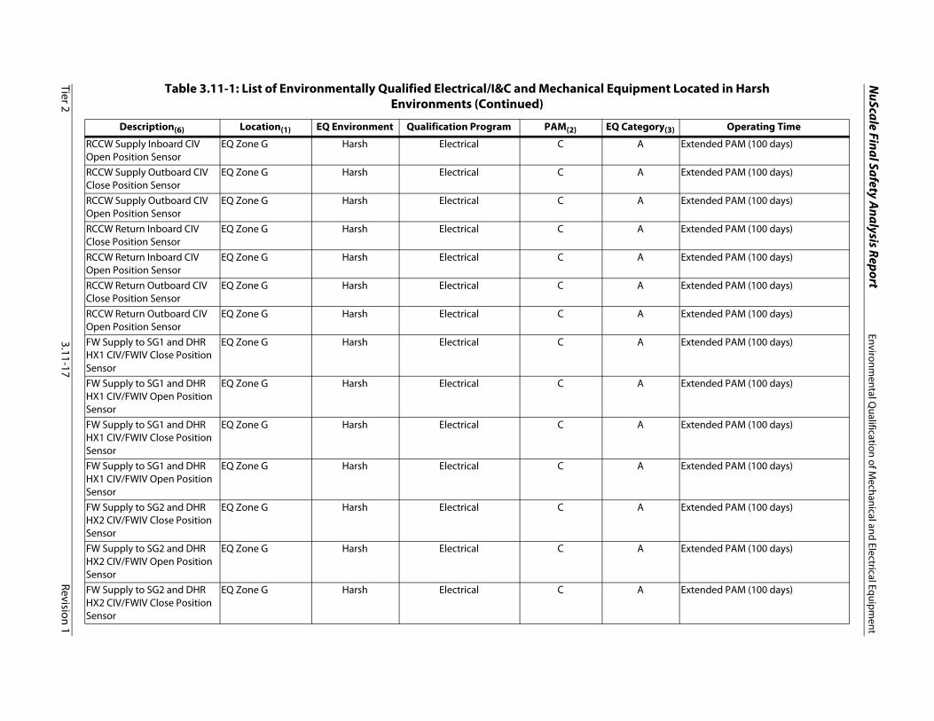
NuScale Final Safety A
nalysis ReportEnvironm
ental Qualification of M
echanical and Electrical Equipment
Tier 23.11-17
Revision 1
RCCW Supply Inboard CIV Open Position Sensor
EQ Zone G Harsh Electrical C A Extended PAM (100 days)
RCCW Supply Outboard CIV Close Position Sensor
EQ Zone G Harsh Electrical C A Extended PAM (100 days)
RCCW Supply Outboard CIV Open Position Sensor
EQ Zone G Harsh Electrical C A Extended PAM (100 days)
RCCW Return Inboard CIV Close Position Sensor
EQ Zone G
Harsh Electrical C A Extended PAM (100 days)
RCCW Return Inboard CIV Open Position Sensor
EQ Zone G Harsh Electrical C A Extended PAM (100 days)
RCCW Return Outboard CIV Close Position Sensor
EQ Zone G
Harsh Electrical C A Extended PAM (100 days)
RCCW Return Outboard CIV Open Position Sensor
EQ Zone G Harsh Electrical C A Extended PAM (100 days)
FW Supply to SG1 and DHR HX1 CIV/FWIV Close Position Sensor
EQ Zone G Harsh Electrical C A Extended PAM (100 days)
FW Supply to SG1 and DHR HX1 CIV/FWIV Open Position Sensor
EQ Zone G Harsh Electrical C A Extended PAM (100 days)
FW Supply to SG1 and DHR HX1 CIV/FWIV Close Position Sensor
EQ Zone G Harsh Electrical C A Extended PAM (100 days)
FW Supply to SG1 and DHR HX1 CIV/FWIV Open Position Sensor
EQ Zone G Harsh Electrical C A Extended PAM (100 days)
FW Supply to SG2 and DHR HX2 CIV/FWIV Close Position Sensor
EQ Zone G Harsh Electrical C A Extended PAM (100 days)
FW Supply to SG2 and DHR HX2 CIV/FWIV Open Position Sensor
EQ Zone G Harsh Electrical C A Extended PAM (100 days)
FW Supply to SG2 and DHR HX2 CIV/FWIV Close Position Sensor
EQ Zone G Harsh Electrical C A Extended PAM (100 days)
Table 3.11-1: List of Environmentally Qualified Electrical/I&C and Mechanical Equipment Located in Harsh Environments (Continued)
Description(6) Location(1) EQ Environment Qualification Program PAM(2) EQ Category(3) Operating Time

NuScale Final Safety A
nalysis ReportEnvironm
ental Qualification of M
echanical and Electrical Equipment
Tier 23.11-18
Revision 1
FW Supply to SG2 and DHR HX2 CIV/FWIV Open Position Sensor
EQ Zone G Harsh Electrical C A Extended PAM (100 days)
SG1 Steam Supply CIV/MSIV Close Position Sensor
EQ Zone G Harsh Electrical C A Extended PAM (100 days)
SG1 Steam Supply CIV/MSIV Open Position Sensor
EQ Zone G
Harsh Electrical C A Extended PAM (100 days)
SG1 Steam Supply CIV/MSIV Close Position Sensor
EQ Zone G Harsh Electrical C A Extended PAM (100 days)
SG1 Steam Supply CIV/MSIV Open Position Sensor
EQ Zone G Harsh Electrical C A Extended PAM (100 days)
SG1 Steam Supply CIV/MS Bypass Isolation Valve Close Position Sensor
EQ Zone G Harsh Electrical C A Extended PAM (100 days)
SG1 Steam Supply CIV/MS Bypass Isolation Valve Open Position Sensor
EQ Zone G Harsh Electrical C A Extended PAM (100 days)
SG1 Steam Supply CIV/MS Bypass Isolation Valve Close Position Sensor
EQ Zone G Harsh Electrical C A Extended PAM (100 days)
SG1 Steam Supply CIV/MS Bypass Isolation Valve Open Position Sensor
EQ Zone G Harsh Electrical C A Extended PAM (100 days)
SG2 Steam Supply CIV/MSIV Close Position Sensor
EQ Zone G Harsh Electrical C A Extended PAM (100 days)
SG2 Steam Supply CIV/MSIV Open Position Sensor
EQ Zone G Harsh Electrical C A Extended PAM (100 days)
SG2 Steam Supply CIV/MSIV Close Position Sensor
EQ Zone G Harsh Electrical C A Extended PAM (100 days)
SG2 Steam Supply CIV/MSIV Open Position Sensor
EQ Zone G Harsh Electrical C A Extended PAM (100 days)
SG2 Steam Supply CIV/MS Bypass Isolation Valve Close Position Sensor
EQ Zone G Harsh Electrical C A Extended PAM (100 days)
Table 3.11-1: List of Environmentally Qualified Electrical/I&C and Mechanical Equipment Located in Harsh Environments (Continued)
Description(6) Location(1) EQ Environment Qualification Program PAM(2) EQ Category(3) Operating Time

NuScale Final Safety A
nalysis ReportEnvironm
ental Qualification of M
echanical and Electrical Equipment
Tier 23.11-19
Revision 1
SG2 Steam Supply CIV/MS Bypass Isolation Valve Open Position Sensor
EQ Zone G Harsh Electrical C A Extended PAM (100 days)
SG1 Steam Supply CIV/MS Bypass Isolation Valve Close Position Sensor
EQ Zone G Harsh Electrical C A Extended PAM (100 days)
SG1 Steam Supply CIV/MS Bypass Isolation Valve Open Position Sensor
EQ Zone G Harsh Electrical C A Extended PAM (100 days)
Steam Generator System (SGS-A014)Thermal relief valves EQ Zone C Harsh Mechanical N/A B Extended Term (<= 720 hr)Control Rod Drive System (CRDS-A022)
-
Control Rod Drive Coils EQ Zone E Harsh Electrical N/A A Short Term (<= 1 hr)Rod Position Indication (RPI) Coils
EQ Zone E Harsh Electrical N/A B Extended Term (<= 720 hr)
CRDM Control Cabinet EQ Zone N Harsh Electrical N/A A Short Term (<= 1 hr)Rod Position Indication Cabinets (Train A/B)
EQ Zone N Harsh Electrical N/A B Long Term (<= 72 hr)
CRDS Cooling Water Piping and Pressure Relief Valve
EQ Zone EEQ Zone F
Harsh Mechanical N/A B Extended Term (<= 720 hr)
Reactor Coolant System (RCS-A030)
-
PZR Control Cabinet EQ Zone KEQ Zone L
Harsh Electrical N/A AB
A Short Term (<= 1 hr)
Reactor Safety Valve Position Indicator
EQ Zone E Harsh Electrical N/A B Extended Term (<= 720 hr)
Reactor Safety Valves EQ Zone E Harsh ElectricalMechanical
C A Extended PAM (100 days)
Narrow Range Pressurizer Pressure Elements
EQ Zone D EQ Zone E
Harsh Electrical N/A A Short Term (<= 1 hr)
Wide Range RCS Pressure EQ Zone D EQ Zone E
Harsh Electrical C A Extended PAM (100 days)
Table 3.11-1: List of Environmentally Qualified Electrical/I&C and Mechanical Equipment Located in Harsh Environments (Continued)
Description(6) Location(1) EQ Environment Qualification Program PAM(2) EQ Category(3) Operating Time

NuScale Final Safety A
nalysis ReportEnvironm
ental Qualification of M
echanical and Electrical Equipment
Tier 23.11-20
Revision 1
PZR/RPV Level EQ Zone EEQ Zone FEQ Zone G
Harsh Electrical B A Extended Term (<= 720 hr)
Narrow Range RCS Hot Leg Temperature Element
EQ Zone C Harsh Electrical N/A A Short Term (<= 1 hr)
Wide Range RCS Hot Leg Temperature Element
EQ Zone C Harsh Electrical B A Extended Term (<= 720 hr)
Wide Range RCS Cold Leg Temperature Element
EQ Zone B Harsh Electrical N/A B Extended Term (<= 720 hr)
RCS Flow Transmitter (Ultrasonic)
EQ Zone B Harsh Electrical D A Extended Term (<= 720 hr)
NSSS Primary Systems - Chemical and Volume Control System (CVCS-B010)
-
DWS Supply Isolation Valve EQ Zone J Harsh ElectricalMechanical
N/A AB
Short Term (<= 1 hr) Extended Term (<= 720 hr)
DWS Supply Isolation Valve EQ Zone J Harsh ElectricalMechanical
N/A AB
Short Term (<= 1 hr) Extended Term (<= 720 hr)
DWS Supply Isolation Valve Position Indication
EQ Zone J Harsh Electrical D A Extended Term (<= 720 hr)
DWS Supply Isolation Valve Position Indication
EQ Zone J Harsh Electrical D A Extended Term (<= 720 hr)
Discharge Spoolpiece Drain Valve
EQ Zone J Harsh ElectricalMechanical
N/A A Short Term (<= 1 hr) Extended Term (<= 720 hr)
Discharge PSS Isolation Valve EQ Zone J Harsh ElectricalMechanical
N/A A Short Term (<= 1 hr) Extended Term (<= 720 hr)
RPV High Point Degasification Isolation Valve
EQ Zone G Harsh ElectricalMechanical
C A Short Term (<= 1 hr)Extended PAM (100 days)
Spray Check Valve EQ Zone G Harsh Mechanical N/A AB
Short Term (<= 1 hr) Extended Term (<= 720 hr)
Injection Check Valve EQ Zone G Harsh Mechanical N/A AB
Short Term (<= 1 hr) Extended Term (<= 720 hr)
Emergency Core Cooling System (ECCS-B020)
-
Table 3.11-1: List of Environmentally Qualified Electrical/I&C and Mechanical Equipment Located in Harsh Environments (Continued)
Description(6) Location(1) EQ Environment Qualification Program PAM(2) EQ Category(3) Operating Time
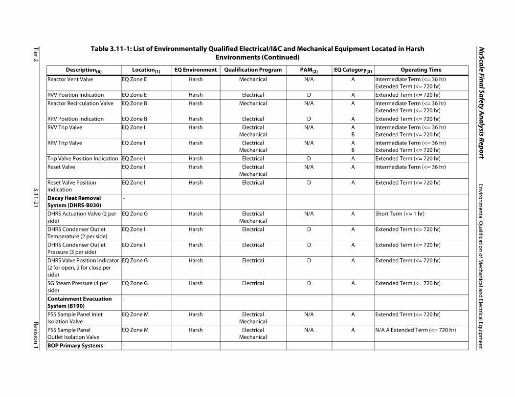
NuScale Final Safety A
nalysis ReportEnvironm
ental Qualification of M
echanical and Electrical Equipment
Tier 23.11-21
Revision 1
Reactor Vent Valve EQ Zone E Harsh Mechanical N/A A Intermediate Term (<= 36 hr) Extended Term (<= 720 hr)
RVV Position Indication EQ Zone E Harsh Electrical D A Extended Term (<= 720 hr)Reactor Recirculation Valve EQ Zone B Harsh Mechanical N/A A Intermediate Term (<= 36 hr)
Extended Term (<= 720 hr)RRV Position Indication EQ Zone B Harsh Electrical D A Extended Term (<= 720 hr)RVV Trip Valve EQ Zone I Harsh Electrical
MechanicalN/A A
BIntermediate Term (<= 36 hr) Extended Term (<= 720 hr)
RRV Trip Valve EQ Zone I Harsh ElectricalMechanical
N/A AB
Intermediate Term (<= 36 hr) Extended Term (<= 720 hr)
Trip Valve Position Indication EQ Zone I Harsh Electrical D A Extended Term (<= 720 hr)Reset Valve EQ Zone I Harsh Electrical
MechanicalN/A A Intermediate Term (<= 36 hr)
Reset Valve Position Indication
EQ Zone I Harsh Electrical D A Extended Term (<= 720 hr)
Decay Heat Removal System (DHRS-B030)
-
DHRS Actuation Valve (2 per side)
EQ Zone G Harsh ElectricalMechanical
N/A A Short Term (<= 1 hr)
DHRS Condenser Outlet Temperature (2 per side)
EQ Zone I Harsh Electrical D A Extended Term (<= 720 hr)
DHRS Condenser Outlet Pressure (3 per side)
EQ Zone I Harsh Electrical D A Extended Term (<= 720 hr)
DHRS Valve Position Indicator (2 for open, 2 for close per side)
EQ Zone G Harsh Electrical D A Extended Term (<= 720 hr)
SG Steam Pressure (4 per side)
EQ Zone G Harsh Electrical D A Extended Term (<= 720 hr)
Containment Evacuation System (B190)
-
PSS Sample Panel Inlet Isolation Valve
EQ Zone M Harsh ElectricalMechanical
N/A A Extended Term (<= 720 hr)
PSS Sample PanelOutlet Isolation Valve
EQ Zone M Harsh ElectricalMechanical
N/A A N/A A Extended Term (<= 720 hr)
BOP Primary Systems -
Table 3.11-1: List of Environmentally Qualified Electrical/I&C and Mechanical Equipment Located in Harsh Environments (Continued)
Description(6) Location(1) EQ Environment Qualification Program PAM(2) EQ Category(3) Operating Time

NuScale Final Safety A
nalysis ReportEnvironm
ental Qualification of M
echanical and Electrical Equipment
Tier 23.11-22
Revision 1
Fuel Handling Equipment (FHE-B140)
-
Fuel Handling Machine EQ Zone H Harsh Electrical Mechanical
N/A B Extended Term (<= 720 hr)
Reactor Pool Cooling System (RPCS-B173)
-
Instrumentation - temperature (24 total)
EQ Zone I Harsh Electrical D A Extended Term (<= 720 hr)
Ultimate Heat Sink (UHS-B175)
-
Pool Level instruments EQ Zone I Harsh Electrical D A Extended Term (<= 720 hr)
Balance of Plant Systems - Main Steam System (MSS-C010)
-
Secondary Main Steam Isolation Valve
EQ Zone M Harsh ElectricalMechanical
N/A AB
Short Term (<= 1 hr) Extended Term (<= 720 hr)
Secondary Main Steam Isolation Valve Close Position Indicator
EQ Zone M Harsh Electrical D A Extended Term (<= 720 hr)
Secondary Main Steam Isolation Valve Open Position Indicator
EQ Zone M Harsh Electrical D A Extended Term (<= 720 hr)
Secondary Main Steam Isolation Bypass Valve
EQ Zone M Harsh ElectricalMechanical
N/A AB
Short Term (<= 1 hr) Extended Term (<= 720 hr)
Table 3.11-1: List of Environmentally Qualified Electrical/I&C and Mechanical Equipment Located in Harsh Environments (Continued)
Description(6) Location(1) EQ Environment Qualification Program PAM(2) EQ Category(3) Operating Time

NuScale Final Safety A
nalysis ReportEnvironm
ental Qualification of M
echanical and Electrical Equipment
Tier 23.11-23
Revision 1
Secondary Main Steam Isolation Bypass Valve Close Position Indicator
EQ Zone M Harsh Electrical D A Extended Term (<= 720 hr)
Secondary Main Steam Isolation Bypass Valve Open Position Indicator
EQ Zone M Harsh Electrical D A Extended Term (<= 720 hr)
Secondary Main Steam Isolation Bypass Valve
EQ Zone M Harsh ElectricalMechanical
N/A AB
Short Term (<= 1 hr) Extended Term (<= 720 hr)
Secondary Main Steam Isolation Bypass Valve Close Position Indicator
EQ Zone M Harsh Electrical D A Extended Term (<= 720 hr)
Secondary Main Steam Isolation Bypass Valve Open Position Indicator
EQ Zone M Harsh Electrical D A Extended Term (<= 720 hr)
Condensate and Feedwater System (FWS-C020)
-
Feedwater Regulating Valve A/B
EQ Zone M Harsh ElectricalMechanical
D A Extended Term (<= 720 hr)
Feedwater Regulating Valve A/B Position Indicator
EQ Zone M Harsh Electrical D A Extended Term (<= 720 hr)
Feedwater Supply Check Valve
EQ Zone M Harsh Mechanical N/A A Extended Term (<= 720 hr)
Instrumentation and Controls
-
Module Protection System (MPS-E011)
-
Separation Group A ‐ Under‐the‐BioshieldTemperature Sensors
EQ Zone G Harsh Electrical D A Extended Term (<= 720 hr)
Separation Group B ‐ Under‐the‐BioshieldTemperature Sensors
EQ Zone G Harsh Electrical D A Extended Term (<= 720 hr)
Separation Group C ‐ Under‐the‐BioshieldTemperature Sensors
EQ Zone G Harsh Electrical D A Extended Term (<= 720 hr)
Table 3.11-1: List of Environmentally Qualified Electrical/I&C and Mechanical Equipment Located in Harsh Environments (Continued)
Description(6) Location(1) EQ Environment Qualification Program PAM(2) EQ Category(3) Operating Time

NuScale Final Safety A
nalysis ReportEnvironm
ental Qualification of M
echanical and Electrical Equipment
Tier 23.11-24
Revision 1
Separation Group D ‐ Under‐the‐BioshieldTemperature Sensors
EQ Zone G Harsh Electrical D A Extended Term (<= 720 hr)
MCR Isolation Switches EQ Zone K Harsh Electrical N/A B Extended Term (<= 720 hr)Neutron Monitoring System (NMS-E013)
-
NMS‐Flood Highly Sensitive Neutron Detectors (forCNV flooding events)
EQ Zone I Harsh Electrical B A Extended Term (<= 720 hr)
NMS - Excore NeutronDetectors
EQ Zone I Harsh Electrical B A Extended Term (<= 720 hr)
In-Core Instrumentation System (ICI-E034)
-
In-core instrument string/ temperature sensors
EQ Zone E EQ Zone F
Harsh Electrical C A Extended PAM (100 days)
In-core instrument string sheath
EQ Zone E Harsh Mechanical N/A B Extended Term (<= 720 hr)
Radiation Monitoring System (RMS-E120)
-
RM system that monitors PAM B & C variables
EQ Zones G Harsh Electrical C A Extended PAM (100 days)
Buildings and Structures - Reactor Building Cranes (RBC-F011)
-
Table 3.11-1: List of Environmentally Qualified Electrical/I&C and Mechanical Equipment Located in Harsh Environments (Continued)
Description(6) Location(1) EQ Environment Qualification Program PAM(2) EQ Category(3) Operating Time

NuScale Final Safety A
nalysis ReportEnvironm
ental Qualification of M
echanical and Electrical Equipment
Tier 23.11-25
Revision 1
Reactor Building Crane EQ Zone H Harsh ElectricalMechanical
N/A B Extended Term (<= 720 hr)
Notes:1. Environmental Zone Locations are delineated in Table 3.11-2.2. PAM Type Variables:
• Type B: those variables that provide information to indicate whether plant design functions related to safety are being accomplished.• Type C: those variables to be monitored to provide information to indicate whether the primary reactor containment, the fuel cladding, or the reactor coolant pressure
boundary remain intact and do not have a potential to be breached.• Type D: those variables that provide information to indicate the operation of individual safety systems and other systems that perform design functions related to
safety. These variables are to help the operator make appropriate decisions in using the individual systems performing design functions related to safety in mitigating the consequences of an accident.
• For PAM variables that are assigned multiple types (e.g., B, C, D), the indicated type reflects the type that results in the longest operating time requirement.3. EQ Categories:
• A Equipment that will experience the environmental conditions of design basis accidents for which it must function to mitigate said accidents, and that will be qualified to demonstrate operability in the accident environment for the time required for accident mitigation with safety margin to failure.
• B Equipment that will experience the environmental conditions of design basis accidents through which it need not function for mitigation of said accidents, but through which it must not fail in a manner detrimental to plant safety or accident mitigation, and that will be qualified to demonstrate the capability to withstand the accident environment for the time during which it must not fail with safety margin to failure.
4. This listing is based on a single module evaluation and does not consider multi-module interactions because the secondary module(s) effects that may be created by theprimary module affected are enveloped by their own qualifications.
5. Refer to Section 6.2.4 for information regarding subcomponents on the hydraulic skid.6. All commodities will be qualified for the environmental conditions they will be subjected to. Examples of commodity items that may be subject to environmental
qualification includes, but are not limited to, equipment items such as cables, connectors, electrical splices, conduit seals, thread sealants, terminal blocks, or lubricants.
Table 3.11-1: List of Environmentally Qualified Electrical/I&C and Mechanical Equipment Located in Harsh Environments (Continued)
Description(6) Location(1) EQ Environment Qualification Program PAM(2) EQ Category(3) Operating Time

NuScale Final Safety Analysis Report Environmental Qualification of Mechanical and Electrical Equipment
Tier 2 3.11-26 Revision 1
Table 3.11-2: Environmental Qualification Zones - Reactor Building
EQ Zone(1) Description Environment
A Room 010-022, Containment Vessel - bottom of containment (6") to bottom of upper core plate (142")
Harsh
B Room 010-022, Containment Vessel - bottom of upper core plate
(142") to bottom of riser transition (236")Harsh
C Room 010-022, Containment Vessel - bottom of riser transition (236") to bottom of baffle plate (587")
Harsh
D Room 010-022, Containment Vessel - bottom of baffle plate (587") to top of pressurizer (697")
Harsh
E Room 010-022, Containment Vessel - top of pressurizer (697") to bottom of torispherical head (841")
Harsh
F Room 010-022, Containment Vessel - bottom of torispherical head (841") to top of containment (904")
Harsh
G Room 010-022, Module pool bay vapor space - outside containment and under the BioShield (Top of Module) (Figure 1.2-19: Reactor Building East and West Section View)
Harsh
H Rooms 010-022, 010-422, and 010-423 above pool level to ceiling (RXB Pool Room Vapor Space) (Figure 1.2-16: Reactor Building 100'-0"' Elevation thru Figure 1.2-18: Reactor Building 145'-6" Elevation)
Harsh
I Room 010-022, 010-023 and 010-024 up to top of pool level (RXB Pool Room liquid space) (Figure 1.2-10: Reactor Building 24'-0" Elevation)
Harsh
J Rooms 010-101, 010-102, 010-103, 010-104, 010-005, 010-106, 010-107, 010-112, 010-114, 010-115, 010-116, 010-117, 010-118, 010-119, 010-120, 010-121, 010-122, 010-123, 010-125, 010-126, 010-127, 010-128, 010-129, 010-130, 010-131, 010-133, 010-134 (Figure 1.2-12: Reactor Building 50'-0" Elevation)
Harsh
K Rooms 010-201, 010-202, 010-203, 010-204, 010-005, 010-206, 010-207, 010-208, 010-242, 010-275 (Figure 1.2-14: Reactor Building 75'-0" Elevation)
Harsh

NuScale Final Safety Analysis Report Environmental Qualification of Mechanical and Electrical Equipment
Tier 2 3.11-27 Revision 1
L Rooms 010-201, 010-202, 010-203, 010-204, 010-005(Figure 1.2-15: Reactor Building 86'-0" Elevation)
Harsh
M Rooms 010-005, 010-401, 010-402, 010-403, 010-404, 010-405, 010-406, 010-407, 010-408, 010-409, 010-410, 010-411, 010-412, 010-414, 010-415, 010-416, 010-417, 010-418, 010-419, 010-420 (Figure 1.2-16: Reactor Building 100'-0" Elevation)
Harsh
N Rooms 010-005, 010-501, 010-502, 010-503, 010-504, 010-506, 010-507, 010-508, 010-509, 010-510 (Figure 1.2-17: Reactor Building 126'-0" Elevation)
Harsh
Note:
1) EQ Zones listed are those areas within the Reactor Building that are harsh environments and contain equipment that requires environmental qualification.
Table 3.11-2: Environmental Qualification Zones - Reactor Building (Continued)
EQ Zone(1) Description Environment

NuScale Final Safety Analysis ReportASME Code Class 1, 2, and 3 Piping Systems, Piping Components and
Associated Supports
Tier 2 3.12-1 Revision 1
3.12 ASME Code Class 1, 2, and 3 Piping Systems, Piping Components and Associated Supports
3.12.1 Introduction
This section addresses the design of the piping systems and piping supports used in Seismic Category I, Seismic Category II, and nonsafety-related systems. The information in this section primarily addresses ASME Class 1, 2, and 3 piping systems. The analysis of the piping also considers interaction of non-Seismic Category I piping and associated supports with Seismic Category I piping and associated supports.
NuScale has adapted a graded level of detail approach in piping design. This approach is discussed in the March 4, 2014 NRC white paper - Piping Level of Detail for Design Certification (Reference 3.12-12). Piping system designs (e.g., layout, pipe size) for the systems within the NuScale Power Module (NPM) are generally complete and the requirements for the design, analysis, materials, fabrication, inspection, examination, testing, certification, packaging, shipping, and installation of these systems are documented in an ASME design specification for Class 1, 2, & 3 piping. The highest level of detail is complete for Class 1 reactor coolant pressure boundary (RCPB) piping (NPS 2) inside containment and Class 2 main steam, feedwater and decay heat removal system (DHRS) lines up to the first 6-way rigid restraint beyond the containment isolation valves. Preliminary analyses are performed for these systems in order to confirm the adequacy of the piping layout and support locations. Preliminary analyses consider deadweight, thermal expansion/contraction and seismic loads. For preliminary analyses, ASME Class 2 rules may be used for ASME Class 1 piping. Additionally, detailed stress analyses are performed for two representative systems, the RCS discharge line and the feedwater line. The RCS discharge piping is selected because it is representative of the ASME Class 1 piping with respect to deadweight, seismic, thermal transient and fatigue loading. The discharge line is longer than the other Class 1 lines, with more seismic supports and longer spans between restraints. Therefore, this analysis presents the more challenging analysis case. The feedwater line is selected because it experiences bounding loads for the Class 2 systems with respect to the leak-before-break (LBB) analysis. Detailed stress analyses include loads from deadweight, seismic (dynamic), thermal expansion/contraction, and for Class 1 lines, fatigue (including environmentally assisted fatigue evaluation in conformance to Regulatory Guide (RG) 1.207. The results of these analyses confirm the acceptability of the piping designs.
3.12.2 Codes and Standards
10 CFR 50, Appendix A, General Design Criterion (GDC) 1 requires that structures, systems, and components (SSC) must be designed to quality standards commensurate with the importance of the safety functions to be performed. GDC 2 requires that SSC be designed to withstand the effects of natural phenomena such as earthquakes, tornadoes, and floods without the loss of their safety function. GDC 4 requires that the nuclear power plant SSC be designed to accommodate the effects of and be compatible with the environmental conditions associated with normal operation, maintenance, testing, and postulated accidents, including loss-of-coolant accidents (LOCAs). GDC 14 requires that reactor coolant pressure boundary of the primary piping systems being designed, fabricated, constructed, and tested to have an extremely low probability of abnormal leakage, of rapidly propagating failure, and gross rupture. GDC 15 requires reactor coolant systems

NuScale Final Safety Analysis ReportASME Code Class 1, 2, and 3 Piping Systems, Piping Components and
Associated Supports
Tier 2 3.12-2 Revision 1
(RCSs) and associated auxiliary, control, and protection systems be designed with sufficient margin to assure that the design condition of normal operation, including anticipated operational occurrences.
Codes and standards used in the design of piping systems and piping supports are consistent with 10 CFR 50, Appendix A, GDCs 1, 2, 4, 14, 15, and 10 CFR 50 Appendix S as discussed in the following sections. The design codes for ASME Class 1, 2 and 3 piping systems are described below.
3.12.2.1 ASME Boiler and Pressure Vessel Code
The design code specified for ASME Code Section III Class 1, 2, and 3 piping in the NuScale design is in Reference 3.12-1. The conditions of use for ASME BPVC Section III (Reference 3.9-1) is applied in accordance with 10 CFR 50.55a (b)(1) as applicable to the 2013 Edition.
The portions of the Code which provide the design requirements for ASME Class 1, 2, 3 piping and supports are provided below:
• Class 1 piping is designed under the design requirements of BPVC Section III, Subarticle NB-3600.
• Class 2 Piping is designed under the design requirements of BPVC Section III, Subarticle NC-3600.
• Class 3 piping is designed under the design requirements of BPVC Section III, Subarticle ND-3600.
• Class 1, 2, 3 Piping supports are designed under the design requirements of BPVC Section III, Subarticle NF.
Note that there are some specific exceptions in the procedures of the Code which allow for analyzing components to other Section III subarticles in some circumstances (e.g. Class 2 components designed to Subarticle NB-3600).
Quality Group D (RG 1.26) piping is designed and analyzed to the latest edition of ASME B31.1 (Reference 3.12-3).
3.12.2.2 ASME Code Cases
ASME Code Cases may be used if they are either conditionally or unconditionally approved in Regulatory Guide (RG) 1.84, Revision 36.
3.12.2.3 Design Specification
Design specifications are required for ASME Code Class 1, 2, and 3 piping, piping components and associated supports per the ASME BPVC Section III. Additionally, conformance to these Design Specifications for the as-designed piping, piping components, and associated supports is required per the Code to be documented in Design Reports.

NuScale Final Safety Analysis ReportASME Code Class 1, 2, and 3 Piping Systems, Piping Components and
Associated Supports
Tier 2 3.12-3 Revision 1
3.12.3 Piping Analysis Methods
3.12.3.1 Experimental Stress Analyses Methods
Experimental stress analysis methods are not used to qualify piping for the NuScale Power Plant design.
3.12.3.2 Modal Response Spectrum Method
The effects of the ground motion during a safe shutdown earthquake (SSE) event are transmitted through structures and components to the piping systems at support and anchorage locations. Seismic Category I piping systems are required to be designed to withstand the effects of the SSE and maintain the capability of performing their safety functions. A dynamic method of analysis used for piping systems is the response spectrum method. This analysis method applies in-structure response spectra (which are amplified from the fundamental seismic ground motion spectra) to the piping system in all three directions. The response spectra are determined from time-history motion of the structure applied through single-degree-of-freedom harmonic oscillators. The maximum response of the oscillators throughout the duration of the event, for a range of natural frequencies, is taken to be the response spectra curve.
The in-structure response spectra are applied to the locations where the piping system is attached to or supported by the structure, such as piping supports or vessel nozzles. In-structure response spectra of the NPM are determined using dynamic analysis of a a three-dimensional, finite element model of the NuScale Power Module structural system as described in NuScale Power Module Analysis Technical Report TR-0916-51502 (Reference 3.12-13) for piping that is attached to the NuScale Power Module (NPM). For piping which is attached to the building, the in-structure response spectra of the Reactor Building is used, which is described in Section 3.7. The response spectrum analysis is performed using either the uniform support motion (USM) method or the independent support motion (ISM) method.
Analysis using the response spectrum method is performed linearly by transforming the coupled equations of motion for a multiple degree-of-freedom system into a set of uncoupled modal response equations. The maximum modal responses are evaluated and combined using approximate rules to account for phasing of the modes. The combination of maximum modal responses is a generally conservative approach. The modal responses and spatial responses of the piping system are combined using the methods described below.
3.12.3.2.1 Development of In-structure Response Spectra
To perform the response spectrum analysis, an in-structure response spectra must be developed for the structures that support the piping system anchors. The methods and guidance in RG 1.122 Revision 1 are used to develop the in-structure response spectra.
The in-structure response spectra shall include accelerations for three orthogonal directions (two horizontal and one vertical) from the time history motions of the supporting structure. Uncertainties in the structural frequencies which represent

NuScale Final Safety Analysis ReportASME Code Class 1, 2, and 3 Piping Systems, Piping Components and
Associated Supports
Tier 2 3.12-4 Revision 1
uncertainty or approximations of material and structural properties are accounted for by smoothing and peak broadening the raw in-structure response spectra. The methods and guidance of RG 1.122 are used for smoothing and peak broadening the raw spectra. If the frequency broadening is not determined using the frequency dependent procedure in RG 1.122, then the response spectra are peak broadened by ±15 percent.
3.12.3.2.2 Uniform Support Motion
For piping systems which may be supported at multiple points within a structure the seismic motions of each support location may vary. An acceptable approach for analyzing these piping systems is to define a uniform response spectrum (URS) that envelops the individual response spectra at the various support locations. This method is referred to as the uniform support motion (USM) method. The methods and guidance of RG 1.92 is used for combining modal and spatial responses for USM method of analysis. Either Revision 3 or Revision 1 of RG 1.92 may be used for the NuScale design. Generally, piping for the NuScale design is analyzed using AutoPIPE software, which does not currently have the capability to separate periodic and rigid components of modal responses. If the software used for analysis does not have the capability to comply entirely with Revision 3 of RG 1.92, the Revision 1 may be used as long as the missing mass effects are also considered. Revision 3 states:
“The methods of combining modal responses, described in Revision 1, remain acceptable. If however, applicants for new licenses choose to use Revision 1 methods for combining modal responses, their analyses should address the residual rigid response of the missing mass modes as discussed in Regulatory Positions C.1.4.1 and C.1.5.1 of this guide.”
When performing analysis of piping systems by the USM method, damping values are applied as permitted by RG 1.61 Revision 1. For analysis of NuScale piping systems, a single damping value of 4 percent for analysis of SSE loads (for all frequencies) is used as permitted by RG 1.61. Frequency dependent damping is not used, though it is conditionally permitted by RG 1.61. If the analysis of a piping model includes other non-piping components (such as supports or structural elements which have different damping values per RG 1.61) then composite modal damping values are determined using one of the two techniques as follows:
Eq. 3.12-1
or
Eq. 3.12-2
1( ) Mass weighted damping: βj ϕ{ }T= M[ ] ϕ{ }
2( ) Stiffness weighted damping: βjϕ{ }T
K[ ] ϕ{ }K∗-----------------------------------=

NuScale Final Safety Analysis ReportASME Code Class 1, 2, and 3 Piping Systems, Piping Components and
Associated Supports
Tier 2 3.12-5 Revision 1
where,
= assembled stiffness matrix,
= equivalent modal damping ratio of the jth mode,
= the modified stiffness or mass matrix constructed from element matrices formed by the product of the damping ratio for the element and its stiffness or mass matrix, and
= jth normalized modal vector.
Note that when composite modal damping is determined using these methods, the damping shall not exceed 20 percent of critical. Equations for determining system composite modal damping are provided in ASCE 4-98 (Reference 3.12-14).
3.12.3.2.3 Modal Combination
The individual modal responses of the piping system due to URS input are not simply summed at each location because it is unlikely that the maximum individual modal responses of piping system supports would occur at the same time during a seismic event. Therefore, modal responses are combined using the methods of Regulatory Guide 1.92 to obtain the representative maximum response of interest from the maximum individual modal responses.
When performing response spectra analyses which comply with Revision 1 of Regulatory Guide 1.92, modal responses of the piping system are only considered below a defined cutoff frequency at which spectral accelerations approximately return to the zero period acceleration (ZPA). Above the ZPA frequency the system is considered to be rigid because the components are not significantly excited by the seismic ground or in-structure motion. However, nuclear power plant SSC may have important natural vibration modes at frequencies higher than the ZPA frequency due to more rigidly restrained components or significant lumped masses near rigid restraints which are not considered in the low frequency modal analysis. Therefore, the contribution of mass associated with modes higher than the ZPA are accounted for as described in Section 3.2.3.2.6.
When performing response spectra analyses which comply with Revision 3 of Regulatory Guide 1.92, the system modal responses are considered to be periodic in the region of amplified spectral displacement, velocity, and acceleration (Regions AB, BC, and CD in Figure 1 of RG 1.92, Revision 3). In the transition region from amplified periodic spectral acceleration to rigid spectral acceleration (region DE in figure 1 of RG 1.92 Revision 3), the response consists of both periodic and rigid components. In the high-frequency regions (regions EF and FG in Figure 1 of RG 1.92, Revision 3 response is considered to be rigid. The combination of modal
K∗ ϕ{ }T K[ ] ϕ{ }=
K[ ]
βj
K[ ] M[ ],
ϕ{ }

NuScale Final Safety Analysis ReportASME Code Class 1, 2, and 3 Piping Systems, Piping Components and
Associated Supports
Tier 2 3.12-6 Revision 1
response components are treated differently in Regulatory Guide 1.92 Revision 3 depending on whether a given mode includes only periodic components, only rigid components, or both periodic and rigid components. Combining the periodic and rigid response components in accordance with procedures of Regulatory Guide 1.92 Revision 3 for all modes provides the total system response to the URS.
3.12.3.2.4 Uniform Support Motion Periodic Modal Responses
When performing response spectrum analysis using the USM method, periodic modal responses shall be combined using the methods and guidance of Regulatory Guide 1.92 Revision 1 or Revision 3. If the frequencies of the modes are sufficiently separated, the square root of the sum of the square (SRSS) method is used:
Eq. 3.12-3
where,
R = the representative maximum response due to the input component of the earthquake,
Rk = the peak response due to the kth mode, and
N = the number of significant modes.
The SRSS method is not applicable if closely spaced modes exist in which case an alternative method of combining modal responses is required. The criteria for defining closely spaced modes is provided by Regulatory Guide 1.92, Revision 3 and the determination is dependent on the critical damping ratio:
1) For critical damping ratios ≤ 2 percent, modes are considered closely spaced if the frequencies are within 10 percent of each other (i.e., for fi < fj, fj ≤ 1.1 fi). Where fi and fj are frequencies of adjacent modes.
2) For critical damping ratios >2 percent, modes are considered closely spaced if the frequencies are within five times the critical damping ratio of each other (i.e., for fi < fj and 5 percent damping, fj ≤ 1.25 fi; for fi < fj and 10 percent damping, fj ≤ 1.5 fi).
For a system which has closely spaced modes, the double sum methods are used to combine the periodic modal responses. These double sum equations include modal correlation coefficients which are uniquely defined, depending on the method chosen for evaluating the correlation coefficient.
The modal correlation coefficients are provided in the applicable revision of Regulatory Guide 1.92.
R R2k
k 1=
N
12---
=

NuScale Final Safety Analysis ReportASME Code Class 1, 2, and 3 Piping Systems, Piping Components and
Associated Supports
Tier 2 3.12-7 Revision 1
Absolute Doublesum - RG 1.92 Rev. 1: Equation (8)
Eq. 3.12-4
where,
R = the representative maximum response of the element due to an input component of the earthquake,
Rk = the peak response of the element due to the kth mode,
Rs = the peak response of the element attributed to the sth mode,
N = the number of significant modes, and
= the modal correlation coefficient for modes k and s.
Signed Doublesum - RG 1.92 Rev. 3: Equation (1)
Eq. 3.12-5
where,
RpI = combined periodic response for the Ith component of seismic input motion (I = 1, 2, 3, for one vertical and two horizontal components),
N = the number of significant modes,
= the modal correlation coefficient for modes i and j,
= periodic response or periodic component of a response of mode i, and
= periodic response or periodic component of a response of mode j.
3.12.3.2.5 Uniform Support Motion Rigid Components of Modal Response
In the transition region where modal responses consist of both periodic and rigid components, the response components can be separated by the methods in Regulatory Guide 1.92 Revision 3. Once separated, these rigid components responses and residual rigid responses are combined algebraically.
R RkRss 1=
N
k 1=
N
εks
12---
=
εks
RpI εijRpiRpjj 1=
N
i 1=
N
12---
=
εij
Rpi
Rpj

NuScale Final Safety Analysis ReportASME Code Class 1, 2, and 3 Piping Systems, Piping Components and
Associated Supports
Tier 2 3.12-8 Revision 1
3.12.3.2.6 Residual Rigid Response
The contribution of the "missing mass" of piping systems above the ZPA is accounted for using the method provided in Section C.1.4 of Regulatory Guide 1.92 Revision 3.
For the missing mass method, the modal responses are determined for those modes with natural frequencies less than the ZPA. For each degree-of-freedom included in the dynamic analysis, the fractions of degree-of-freedom mass included and not included in the summation of the modes are determined. Modes higher than the ZPA are assumed to respond in phase with the ZPA and with each other; therefore, they are combined algebraically and applied to the degree-of-freedom masses not included in the low frequency modal analysis (below the ZPA). Additional discussion of the calculation of the missing mass response is provided in Appendix A of Regulatory Guide 1.92 Revision 3.
An alternative approach to including the contribution of high-frequency modes is to use the Static ZPA method provided in Regulatory Guide 1.92 Revision 3.
When combining modal responses using Regulatory Guide 1.92, Revision 1, the residual rigid response of the missing mass modes is accounted for in accordance with Regulatory Positions C.1.4.1 and C.1.5.1 of Regulatory Guide 1.92, Revision 3. The residual rigid response is obtained using the missing mass method of Regulatory Position C.1.4.1. For each of the three components of seismic input motion, the residual rigid response and the modal response calculated with Revision 1 of Regulatory Guide 1.92 are combined using SRSS for the response spectrum method (RG 1.92 Revision 3, Regulatory Position C.1.5.1).
3.12.3.2.7 Uniform Support Motion Complete Inertial Response
The complete (periodic plus rigid) response spectrum analysis solution for each of the three orthogonal component motions (two horizontal and one vertical) is calculated using the methods in Regulatory Guide 1.92 Revision 3. Note that two complete solution methods are presented and either method may be used as long as the applicable required conditions are met. When combining modal responses in accordance with Revision 1 of Regulatory Guide 1.92, the “missing mass” associated with these rigid response components is required to be incorporated by the process described in Section 3.12.3.2.6.
3.12.3.2.8 Directional Combination
Once the complete inertial response is determined, the responses of piping system components due to the seismic inputs in the three orthogonal directions is obtained by SRSS combination method per RG 1.92 Revision 3.
3.12.3.2.9 Seismic Anchor Motion
In addition to dynamic inertia loads imparted to the piping system, the effects of piping anchor motion (displacement) shall also be considered. The maximum

NuScale Final Safety Analysis ReportASME Code Class 1, 2, and 3 Piping Systems, Piping Components and
Associated Supports
Tier 2 3.12-9 Revision 1
relative support displacements are obtained from the structural response calculations or, from the applicable in-structure response spectra.
Support displacements are imposed on the supported piping in the most unfavorable combination. For piping systems where the support locations are within a single structure or on a single component, the seismic motions may be considered to be in-phase, and the relative displacement between supports may be neglected. However, where supports are located on different components or structures, or when the support motions may not be in-phase, the support motions are conservatively assumed to move out-of-phase when evaluating relative displacements between supported locations.
Analyses of piping systems due to seismic anchor motions are performed statically. The system response due to inertial effects and due to anchor motions are combined by the absolute sum method for USM analysis, when combining of the results is necessary. When performing analysis of inertial effects using the ISM method, the response due to anchor motions are combined with inertial effects by the SRSS method, when combining of the results is necessary (NUREG-1061, Volume 4) (Reference 3.12-2).
3.12.3.3 Independent Support Motion Method
The USM method can result in considerable overestimation of seismic responses. Therefore, an alternate method, which is discussed in Section 3.7.3.9, is the independent support motion (ISM) method. The ISM method is generally used for piping systems which are supported by more than one structure, but may be used for piping systems with multiple supports located in a single structure, if appropriate. This method of analysis is performed by grouping piping supports (such as supports attached to the same portion of a structure) and applying a single response spectrum to each group. One group of supports is moved at a time using the input response spectrum specified for those supports, with the other groups being stationary.
As discussed in Section 3.7.3.9, when performing the ISM method of analysis, calculated responses are combined using the methods and guidance of Section 2.4 of NUREG-1061, Volume 4 (Reference 3.12-2). Therefore, for each mode and direction, responses from the individual grouped analyses are combined by absolute summation. Then, spatial (directional) and modal component responses of the piping system are combined as described in Section 3.12.3.2. Per NUREG-1061, Volume 4 (Reference 3.12-2), consideration of closely spaced modes need not be taken into account; therefore, modal results are combined using the SRSS method described in Section 3.12.3.2.4. Responses for modes below the ZPA are treated as periodic responses, while the residual rigid response is calculated using the missing mass method as described in Section 3.12.3.2.6. The low frequency response (periodic response) and the high frequency response (residual rigid response) are combined using the SRSS method. If the responses due to anchor motions are combined with inertial effects, the SRSS method is used as described in Section 3.12.3.2.9; however, the response due to anchor motions may be evaluated separately from inertial effects per ASME Section III NB-3656(b), NC-3655(b), or ND-3655(b). Damping values from Regulatory Guide 1.61 Revision 1 are used when performing analysis using the ISM method. See Section 3.12.3.5 for discussion of appropriate damping.

NuScale Final Safety Analysis ReportASME Code Class 1, 2, and 3 Piping Systems, Piping Components and
Associated Supports
Tier 2 3.12-10 Revision 1
3.12.3.4 Time-History Method
Seismic analysis of piping systems may also be performed using the time history method (as opposed to the response spectrum method). The time history method can provide more realistic results for multiply-supported systems but it requires increased analytical effort. Therefore, the time history method of analysis for seismic input is generally reserved for major components. Analysis of piping system response or component response due to other transient loads such as water hammer, steam hammer, and impingement may also be performed using the time history method (see Section 3.12.5.3).
Time history analysis can be performed by direct integration of the coupled equations of motion or by modal superposition. When the time history method is used to analyze the seismic response of NuScale piping systems the modal superposition method is used. The modal superposition method is performed by decoupling the multiple degree-of-freedom equations of motion by changing the equations of motion from normal (displacement) coordinates to modal coordinates. The equations are solved linearly as single degree-of-freedom equations and then the results for all modes are combined at each time step. Regulatory Guide 1.92 Revision 1 provides acceptable procedures for combining modal responses. Regulatory Guide 1.92 Revision 3 provides acceptable procedures for combining periodic and rigid modal responses of piping components and for including “missing mass” contribution (above the ZPA frequency). Contribution of mass above the ZPA frequency is included in modal superposition time history analyses as described in Regulatory Position C.1.4 of Regulatory Guide 1.92 Revision 3. As stated in C.1.4.1 of RG1.92 Revision 3, the missing mass contribution, scaled to the instantaneous acceleration, is algebraically summed with the transient solution at the corresponding time.
Time step sensitivity evaluations are performed for piping systems which are analyzed by the time history method to show that the selected time step provides acceptable convergence.
Damping of piping systems using the time history method of analysis is per Section 3.12.3.2.2.
For time history analysis where the three components of earthquake motion are calculated separately, the representative maximum response of a piping component can be determined by taking the SRSS of the maximum responses for each of the three spatial components. As stated in Regulatory Position C.2.2 of RG 1.92 Revision 3, if the three components of the earth motion are statistically independent, the maximum response of a piping component can be obtained from algebraic summation of the three component responses at each time step. Alternatively, if the three components of input motion are statistically independent, a single time history analysis may be performed with the three components of earthquake motion applied simultaneously; this effectively achieves algebraic summation.
3.12.3.5 Damping Values
When performing analysis of piping systems by the USM or ISM methods, damping values are applied per RG 1.61. For analysis of NuScale piping systems, the single

NuScale Final Safety Analysis ReportASME Code Class 1, 2, and 3 Piping Systems, Piping Components and
Associated Supports
Tier 2 3.12-11 Revision 1
damping value of 4 percent (for all frequencies) is used in accordance with RG 1.61. Frequency dependent damping is not used, though it is conditionally permitted by RG 1.61. If the analysis of a piping model includes other non-piping components (such as supports or structural elements which have different damping values per RG 1.61), then composite modal damping values are determined using the techniques discussed in Section 3.12.3.2.2.
3.12.3.6 Inelastic Analysis Method
Inelastic analysis methods are not used for the NuScale piping system analysis.
3.12.3.7 Equivalent Static Load Method
The equivalent static load method of seismic analysis is not used for ASME Code Class 1, 2 and 3 piping.
3.12.3.8 Non-seismic/Seismic Interaction (II/I)
The majority of the Seismic Category I piping is located inside of, or outside of and attached to, the containment vessel. All piping, vessels, components and structures inside containment are Seismic Category I. Therefore, the NuScale Power Plant has few Seismic II/I considerations.
For those few cases, such as on the top of the containment where it is not possible or practical to isolate the seismic piping, non-seismic piping which is located in proximity to the seismic Category I piping is classified as seismic Category II and is analyzed and qualified to the same seismic criteria as the seismic Category I piping thereby precluding adverse interaction during the SSE.
The dynamic effects of non-seismic piping which is attached to seismic Category I piping are accounted for by including some portion of the connected non-seismic piping (and supports) in the model of the Category I piping. The non-seismic piping attached to seismic Category I piping is designed such that the adverse interaction during the SSE is precluded. The attached non-Category I piping, up to the first anchor beyond the interface is designed not to cause a failure of the Category I piping during the SSE.
Interaction Evaluation
Non-seismic piping and components may be located in proximity to safety-related piping without being classified as seismic Category II if an interaction evaluation is performed to verify that adverse interaction with the functionality of seismic Category I components will not occur due to the failure of the non-seismic piping during seismic events. Non-seismic piping components are assumed to fail by being put into a freefall condition, and interactions with safety-related components are evaluated based on their relative locations.
For non-seismic piping systems, non-seismic supports are assumed to fail and the flanged connections are also assumed to fail. Non-seismic piping which is welded is

NuScale Final Safety Analysis ReportASME Code Class 1, 2, and 3 Piping Systems, Piping Components and
Associated Supports
Tier 2 3.12-12 Revision 1
assumed to fail at rigid constraint locations. These assumptions for interaction evaluations are made to give the most bounding interaction effects.
3.12.3.9 Seismic Category I Buried Piping
The NuScale design does not include ASME Code Class 1, 2, or 3 piping which is directly buried in soil.
Note, that for the NuScale design the only ASME BPVC Section III Class 1, 2, or 3 piping that is not directly connected or within an NPM is the ASME Class 3 assured makeup line to the reactor pool which provides a means to add inventory to the pool via temporary equipment for long term beyond design basis event support.
If a licensee desires this line to be directly buried in soil, additional analysis methodologies are required to be provided because the ASME BPVC Section III does not address applicable loads of buried piping.
3.12.4 Piping Modeling Technique
3.12.4.1 Computer Codes
The computer codes ANSYS and AutoPIPE are used for the analyses of ASME Code Class 1, 2 and 3, and ASME B31.1 piping.
ANSYS
The computer program ANSYS is used for the design and analysis of NuScale piping systems. This program is used for analysis of piping for applied static loads and for dynamic loads. The dynamic analyses required for seismic evaluations such as response spectrum analysis and time history analysis are performed using ANSYS.
ANSYS is developed by ANSYS Corporation and maintained by NuScale. ANSYS includes pipe elements which have been verified and validated to Nuclear Regulatory Commission (NRC) standards (such as NUREG/CR-1677) (Reference 3.12-16). Additionally, ANSYS is used if a detailed stress analysis (i.e., NB-3200) is performed in lieu of a NB/NC/ND-3600 piping analysis.
AutoPIPE
The computer program AutoPIPE is used for the design and analysis of NuScale piping systems. AutoPIPE is used for analysis of piping due to static loads and for dynamic loads. AutoPIPE also performs design checks for ASME Code Class 1, 2, and 3 and ASME B31.1 piping. The dynamic analyses required for seismic evaluations such as response spectrum analysis and time history analysis are performed using AutoPIPE.
AutoPIPE is developed by Bentley and maintained by NuScale, and has been verified and validated to NRC standards (such as NUREG/CR-1677).

NuScale Final Safety Analysis ReportASME Code Class 1, 2, and 3 Piping Systems, Piping Components and
Associated Supports
Tier 2 3.12-13 Revision 1
3.12.4.2 Dynamic Piping Model
Analytical piping system models are constructed in computer programs to define the masses, geometries, and constraints required to perform the required analyses. These system models are assembled in a three dimensional coordinate system using finite elements. The elements used for piping system models include elastic pipe and beam elements which have stiffness properties which represent equivalent pipe geometry or other piping components. Lumped masses are used at locations of piping components such as valves and flanges. The finite elements are connected at nodes within the model. Nodes are located at structural discontinuities (such as tees, lumped masses, supports locations, nozzle connections etc.) or other locations of interest. Piping supports can be modeled as beam elements or as simple springs with appropriate stiffness values in the constrained directions.
Piping system mass such as the pipe, pipe contents, and insulation weight are modeled as distributed mass. If some of these masses cannot be modeled as distributed then they are modeled by using multiple smaller elements with appropriately divided lumped masses. However, lumped mass spacing are not to be exceeded one half of the length that would produce a natural frequency equal to the ZPA frequency of the seismic input for an equivalent simply supported beam. This ensures that the piping system response remains representative during dynamic analyses.
Torsional effects of eccentric masses (such as a valve operator) are accounted for in the modeling of piping systems if determined to be significant on a case by case basis.
Rigid components of piping systems (natural frequencies above the ZPA frequency) are included in the piping model by placing lumped masses which are rigidly linked to the piping, with the lumped masses located coincident to the centers of gravity of these components. Any integral shield restraints (ISRs) on piping are included in the model as lumped masses. Flexible components are included by using beam elements and lumped masses to maintain representative dynamic response.
The mass of a piping support is included in the piping model (as opposed to a simple constrained boundary condition) if the support mass is greater than 10 percent of the total mass of the supported piping span. The subject span is defined as the piping components to the next support location in both directions from the support considered for inclusion in the model.
3.12.4.3 Piping Benchmark Program
AutoPIPE and ANSYS Comply with NRC benchmarks as described in Section 3.12.4.1.
COL Item 3.12-1: A COL applicant that references the NuScale Power Plant design certification may use a piping analysis program other than the programs listed in Section 3.12.4.1; however, the applicant will implement a benchmark program using the models for the NuScale Power Plant standard design.

NuScale Final Safety Analysis ReportASME Code Class 1, 2, and 3 Piping Systems, Piping Components and
Associated Supports
Tier 2 3.12-14 Revision 1
3.12.4.4 Decoupling Criteria
Decoupling Criteria
The NuScale reactor design is compact, such that there is not a large amount of ASME Class 1, 2 and 3 piping associated with each NPM. Therefore, the piping runs are relatively short and analytical models are generally terminated at structural anchors, which effectively isolate the system from additional static and dynamic effects from beyond the anchor. These structural anchors are typically vessel nozzles, but may also be pipe supports which restrain all six degrees of freedom. Branch lines for which the routing is unknown can be decoupled from the analysis of the main ASME Class 1, 2, or 3 piping run using the criteria discussed below.
All of the ASME Class 1 piping is located inside of the containment vessel, with the exception that the welds connecting the containment isolation valves to the nozzles outside containment are also Class 1 for lines that contain primary coolant. ASME Class 2 piping is located both inside containment and outside containment, but entirely within the NPM disconnect flanges (i.e., does not extend to the reactor building. Therefore, Class 1 or Class 2 piping runs are completely modeled between anchors and do not require decoupling, except for small branch lines, such as instrument lines, for which the routing is unknown. There is a small amount of ASME Class 3 piping connected to each NPM which extends to the Reactor Building. All Class 3 piping is NPS 2-1/2 or smaller; similarly, decoupling methods are used only for small branch lines, such as instrument lines, for which the routing is unknown.
Decoupling methodology may only be applied at a location where the structural interaction between adjacent segments of piping is limited and can be sufficiently accounted for using standard methods. Therefore, this approach may only be used at locations where there is a significant change in pipe size, such as branch lines of larger piping. Branch lines (such as instrument lines) that are smaller than the main run of the analyzed piping may be excluded from the analysis if the moment of inertia of the branch line is less than or equal to 1/25 that of the run pipe (Reference 3.12-18). Additional restrictions on the use of decoupling criteria, which are to be verified upon the completion of the detailed routing of the branch line, are as follows:
1) If an anchor or restraint on the branch pipe is located near the run pipe and significantly restrains the movement of the run pipe, the branch pipe should be included with the model of the run pipe, up to the anchor, or up to and including the series of restraints that effectively permits termination of the model at some point remote from the run pipe (Reference 3.12-18).
2) The branch pipe should be included in the model of the run pipe if the branch is located near a sensitive connection (e.g., equipment nozzle) and more precise magnitudes of reactions are required to determine the acceptability of the loads at the connection (Reference 3.12-18).
3) Decoupling is not permitted if there is a relatively large mass (e.g. large valve or fitting) on the branch line in the span between the connection to the run pipe and the nearest support.

NuScale Final Safety Analysis ReportASME Code Class 1, 2, and 3 Piping Systems, Piping Components and
Associated Supports
Tier 2 3.12-15 Revision 1
These criteria ensure that the effects of the smaller decoupled line on the larger piping can generally be considered negligible. However, stress intensification factors and stress indices associated with the connection of the smaller line are considered in the analysis of the larger piping. Although the detailed routing of the line may be unavailable, the additional mass of the branch is considered for inclusion in the model of the larger piping to account for the decoupled line. When included, the added mass is at least half of the mass of the portion of the decoupled line up to the nearest support.
A separate analysis of the smaller decoupled piping may still be required where dynamic load inputs (e.g., at a branch connection point) are determined from the larger run piping analysis. The connection of the smaller line to the larger pipe is modeled as an anchor in the analysis of the smaller line, with associated stress intensification factors and stress indices applied. Static displacements of the larger piping, including those due to weight, thermal expansion and contraction, and seismic loads, are applied at the connection. If the larger piping is determined to be rigid (i.e. the fundamental frequency is above the cutoff frequency), it is acceptable to apply response spectra at the connection that envelop those of the nearest supports on both the larger piping and the decoupled line. If the larger piping is not determined to be rigid, the inertial seismic loads (e.g. time histories, response spectra) for the decoupled line shall be generated from analysis of the larger piping, in order to account for amplification of the loads.
Overlap Region Methodology
It is preferred to model an entire piping system with relevant connections and supports included in the same analysis. If it is not feasible to analyze a piping system as a single model then the structural overlap methodology provided in NUREG/CR-1980 (Reference 3.12-11) may be used. As discussed above, the NuScale Power Plant is compact and no Class 1 analyses include overlapping models. A limited amount of Class 2 or Class 3 piping analyses may use overlapping models if the routing of the connecting B31.1 piping is not yet completed to the next anchor.
When the structural overlap methodology is applied, the conditions and criteria in Section 2 of NUREG/CR-1980 (Reference 3.12-11) are satisfied. Particularly, it is required that there are at least four rigid restraints in each of three mutually perpendicular directions in the overlap region (including the ends) when the method is applied. For axial restraints only, this requirement may be relaxed to a single restraint in any straight segment. Additionally, piping system analyses which include the overlap region are required to show acceptable results for the piping components and supports in the overlap region.
3.12.5 Piping Stress Analysis Criteria
3.12.5.1 Seismic Input Envelope Versus Site-Specific Spectra
The standard plant piping is evaluated using the certified seismic design response spectra (CSDRS) and the high frequency certified seismic design response spectra (CSDRS-HF) described in Section 3.7.1.1.
NuScale Final Safety Analysis ReportASME Code Class 1, 2, and 3 Piping Systems, Piping Components and
Associated Supports
Tier 2 3.12-16 Revision 1
The floor response spectra are described in detail in Section 3.7.2.5.
COL Item 3.12-2: A COL applicant that references the NuScale Power Plant design certification will confirm that the site-specific seismic response is within the parameters specified in Section 3.7. A COL applicant may perform a site-specific piping stress analysis in accordance with the methodologies described in this section, as appropriate.
3.12.5.2 Design Transients
The piping systems design considers the design transients as discussed in Section 3.9.1.
3.12.5.3 Loadings and Load Combinations
Pressure
The design differential pressure between the inside and outside of the piping pressure boundary components (Pdes) is used for the analysis of ASME Code Class 1, 2, and 3 piping, as well as for ASME B31.1 piping. The minimum required piping wall thickness for ASME Code Class 1, 2, and 3 piping is calculated using NB-3640, NC-3640, and ND3640 at the design pressure using material properties from ASME Section II (Reference 3.12-17) Part D at the applicable design temperature. The design pressure of piping systems includes allowances for pressure addition sources (such as pumps), pressure surges, control system error, and system configuration effects such as static pressure heads. Design pressures (Pdes) and maximum service pressures (P) are used in load combinations as noted in Table 3.12-1 and Table 3.12-2 for calculating stresses considering the condition and service level.
Deadweight
The deadweight of the piping system components is calculated by applying the standard acceleration due to gravity (1g) to the mass of the pipe, the pipe contents, insulation, and other piping components.
Thermal Expansion
The loads on piping components and supports due to restrained thermal expansions and contractions (TE) are considered in the design and analysis of piping systems. Thermal loads appropriate to the mode of operation being analyzed are applied.
The anchors of piping systems may also be subject to thermal expansion, such as thermal anchor motions of equipment nozzles (such as those of the RPV and CNV), support/restraints, and run piping for decoupled branch lines. Thermal anchor motions less than or equal to 1/16th inch are excluded from consideration; this distance represents an industry standard for acceptable gaps in pipe supports upon installation. For decoupled branch lines, thermal anchor motions are obtained from the applicable analysis of the run pipe.
The reference temperature for thermal analysis of piping systems is taken as 70 degrees Fahrenheit. At this reference temperature, loads due to thermal expansion of piping

NuScale Final Safety Analysis ReportASME Code Class 1, 2, and 3 Piping Systems, Piping Components and
Associated Supports
Tier 2 3.12-17 Revision 1
are zero. For ASME Code Class 2 and 3 piping systems with an operating temperature of 150 degrees Fahrenheit or less, thermal analysis is not required except when required due to interface with other components (see Section 3.12.5.14).
Buoyancy
Buoyancy loads (B) are used for piping that is submerged during an applicable load case. Buoyancy is calculated based on the weight of the water displaced.
Seismic
The analyses of ASME Code Class 1, 2 and 3 piping systems and other seismic Category I piping systems include the loads from inertial accelerations and seismic anchor motions (SAMs) due to the seismic ground motions associated with the SSE. All SAMs greater than 1/16th inch are included. Seismic effects are included in piping analyses as Service Level D loads. The applicable in-structure amplifications are used for piping systems supported by other structures and components (such as the reactor building or NuScale Power Module).
For the NuScale plant, the operating basis earthquake (OBE) is defined as 1/3 of the SSE. Any operating reactors will be shut down in the event of an earthquake which exceeds the OBE and checks for damages will be performed by operators. Due to the selection of the OBE as 1/3 of the SSE, the OBE effects are not included as design loads (as allowed by 10 CFR 50 Appendix S), but the OBE cyclic effects are included in fatigue evaluations of ASME Code Class 1 piping.
Relief Valve Thrust
Reaction loads are imparted onto piping system components when relief valves are actuated open. The loads depend on the valve size, valve capacity, the fluid properties, and the valve opening time. For the NuScale design, loads are considered for actuation of reactor safety valves and for actuation of ECCS valves.
Guidance for the design and analysis of safety valve installations is provided in ASME Section III (Reference 3.12-1) Code nonmandatory Appendix O. The analysis of these loads is discussed further in Section 2.12.5.9.
Water and Steam Hammer
Pressures waves are created when the flow of fluid in a piping system is abruptly altered. This can be initiated by mechanisms such as rapid valve actuation, pumps starting, or the collapsing of steam voids. If water or steam hammer loads are credible and significant for a piping system or portion of piping, they are included in the analysis. Thermal-hydraulic modeling software such as RELAP5 or AFT Impulse are used to determine water and steam hammer loads.
Wind, Hurricane, Tornado Loads
ASME Code Class 1 and 2 piping in the NuScale design is not routed in areas that are exposed to wind, hurricane, or tornado loads. If any ASME Code Class 3 piping is routed

NuScale Final Safety Analysis ReportASME Code Class 1, 2, and 3 Piping Systems, Piping Components and
Associated Supports
Tier 2 3.12-18 Revision 1
in locations exposed to wind, hurricanes or tornadoes, the design basis wind loads for the plant (i.e. the design conditions used for the buildings) are included. Should a COL applicant that references the NuScale Power Plant design certification find it necessary to route Class 1, 2, and 3 piping not included in the NuScale Power Plant design certification so that it is exposed to wind, hurricanes, or tornadoes, it must be designed to the plant design basis loads for these events.
Design Basis Pipe Break Loads
The loads due to design basis pipe breaks (DBPB) are included in the analysis of ASME Class 1, 2 and 3 piping for the appropriate service conditions. Loads are imparted onto piping system components in the form of pipe whip, jet impingement, elevated temperatures, and hydraulic dynamic effects. Breaks in the main steam and feedwater lines (inside containment) meet the leak-before-break criteria of NUREG 0800 Section 3.6.3 as discussed in Section 3.6, and therefore, pipe breaks of these lines are not postulated. However, DBPB loads do include the impact of small break loss-of-coolant accident (LOCA), main steam, and feedwater line breaks outside the leak-before-break analyzed zone.
Thermal and Pressure Transient Loads
Thermal and pressure transient loads are included for the analysis of ASME Code Class 1 piping. For ASME Code Class 1 piping, these transient loads are included as Service Level A and B loads and their effects are determined by calculating the primary plus secondary stress intensity ranges, as the piping system goes from one load set (such as pressure, temperature, moment, and force loading) to another load set that follows it in time. The operating experience from NRC Bulletin 88-08 is addressed in Section 3.12.5.7 for Class 1 piping.
For ASME Code Class 2 and 3 piping, transient loads are also considered in the analyses by using the bounding pressure and temperature ranges in individual load combination cases. Loads created by thermal stratification, cycling, or striping that may occur in unisolable piping are accounted for in the design and analysis of the ASME Class 2 and 3 piping per the operating experience from NRC Bulletin 88-08.
The design and analysis of ASME Code Class 1, 2, and 3 piping systems use the applicable design transients addressed in Section 3.9.1
Hydrotests
All piping systems are subject to hydrostatic testing at a pressure higher than the design pressure upon initial assembly of the piping system. The hydrostatic test loads are included for analysis for applicable load cases. The additional weight of the test fluid is considered for the total load of the hydrostatic test (e.g. if the normal service fluid is gas but the test fluid is liquid).
Load Combinations
Using the methodology and equations from the ASME Section III code (Reference 3.12-1), pipe stresses are calculated for various load combinations. The

NuScale Final Safety Analysis ReportASME Code Class 1, 2, and 3 Piping Systems, Piping Components and
Associated Supports
Tier 2 3.12-19 Revision 1
ASME Code includes design limits for Service Levels A, B, C, and D, and testing. Load combinations for ASME Code Class 1 piping are given in Table 3.12-1. Class 2 and 3 load combinations are given in Table 3.12-2.
3.12.5.4 Combination of Modal Responses
The modal combination methods used in response spectrum analyses for piping are addressed in Section 3.12.3.2.
3.12.5.5 Fatigue Evaluation of ASME Code Class 1 Piping
ASME Code Class 1 piping systems and piping components are analyzed for fatigue effects due to cyclic loads. These cyclic loads include applicable thermal transients, hydraulic transients, and external loads such as seismic. Analysis is performed in accordance with the methods and requirements of ASME Code Section III NB-3650.
Additionally, the fatigue analysis of ASME Code Class 1 components incorporate the effects of the light-water reactor environment in accordance with the requirements of Regulatory Guide 1.207 and NUREG/CR-6909.
For fatigue analysis of ASME Code Class 1 piping components, the seismic load includes a minimum of one SSE and five OBE events in accordance with the guidance of SRP 3.7.3. The number of cycles per earthquake can be obtained from the time history used for the system analysis, or a simplified approach is permitted in which a minimum of ten maximum stress cycles per earthquake is used. Alternatively, an equivalent load is considered to be two SSE events, each with ten maximum stress cycles (total of twenty cycles) or the number of fractional vibratory cycles may be used (but with an amplitude not less than 1/3 of the maximum SSE amplitude) when derived in accordance with Annex D of IEEE Std-344 (Reference 3.12-5). When this method is used, and if the amplitude of the vibration is taken as 1/3 of the amplitude of the SSE, then 312 fractional amplitude SSE cycles are considered.
3.12.5.6 Fatigue Evaluation of ASME Code Class 2 and 3 Piping
Design and analysis of ASME Code Class 2 and 3 piping systems and piping components considers fatigue effects if they are subject to a total number of equivalent full temperature cycles greater than 7000 per NC-3611.2. Instead of analyzing ASME Code Class 2 and 3 components for specific cyclic loads (as for Class 1 components using cumulative usage factors), the fatigue effects are addressed by applying stress range reduction factors as provided in NC/ND-3611.2(e) to the allowable stress range for thermal expansion stresses.
3.12.5.7 Thermal Oscillations in Piping Connected to the Reactor Coolant System
The piping sections that can not be isolated and are connected to the reactor coolant system (RCS) can experience temperature stratification and oscillation due to mixing with stagnant lower temperature fluid with the higher temperature fluid at the connection interface (due to turbulent penetrating flow or leakage past an isolation component). These thermal conditions add fatigue loads to piping components due to constrained thermal deflections that must be accounted for by analysis or they can be

NuScale Final Safety Analysis ReportASME Code Class 1, 2, and 3 Piping Systems, Piping Components and
Associated Supports
Tier 2 3.12-20 Revision 1
precluded by design. Thermal oscillations in RCS connected piping were determined to be the cause of pressure boundary component failures at multiple operating nuclear plants as described in NRC Bulletin 88-08 including supplements. Therefore, unisolable sections of piping connected to the RCS of the NuScale design are evaluated for susceptibility to temperature oscillations which may affect the integrity of the components.
The screening criteria and evaluation methodology of Electric Power and Research Institute (EPRI) technical report TR-103581 (Reference 3.12-7) is used to assess unisolable piping connected to the RCS for thermal oscillations in the NuScale design.
For thermal stratification to occur in unisolable piping connected to the RCS which could impose additional fatigue loads on pressure boundary components, the following conditions must exist:
• An isolation component (e.g. a valve) exists in the design with the potential for leakage, which separates stagnant, colder fluid from the RCS. In this configuration a pressure differential must also exist across the isolation component to drive flow through a potential leakage path.
• An unisolable section of stagnant branch piping connected to the RCS that is oriented horizontally or oriented vertically which then transitions to a horizontal run within the span of turbulent RCS penetration (from the point of interface between the branch and the RCS)
Additional fatigue loads are imposed on components when a mechanism exists to promote cycling of the stratified conditions. Depending on the mechanism a large number of fatigue load cycles can be imposed on piping components over their service life. Mechanisms for thermal cycling can be intermittent leaking valves or varying turbulent penetration flow due to changes in RCS velocity in the region of unisolable branch connections.
The following screening criteria are used to evaluate if piping in the NuScale design is susceptible to thermal stratification or cycling:
• Pipe lines, or parts of lines less than or equal to 1 NPS are not susceptible to significant thermal stratification/cycling loads because flow in small lines tends to mix more rapidly than in larger pipe and because small pipe is generally more flexible which reduces the load effects.
• Piping that is connected to the RCS which is vertically oriented or greater than 45 degrees to horizontal for a significant distance is not susceptible to significant thermal loadings due to stratification.
• If sufficient continuous flow is present during normal operations through the line connected to the RCS then thermally stratified conditions are precluded.
The following piping systems connected to the RCS in the NuScale design and are evaluated:
• chemical and volume control system RCS discharge piping
• chemical and volume control system RCS injection piping
NuScale Final Safety Analysis ReportASME Code Class 1, 2, and 3 Piping Systems, Piping Components and
Associated Supports
Tier 2 3.12-21 Revision 1
• pressurizer spray lines
• reactor pressure vessel high point degasification piping
• emergency core cooling system (ECCS) hydraulic lines
The RCS discharge line, RCS injection line, and pressurizer spray lines are not stagnant during power operations, therefore these lines are not susceptible to the adverse thermal stratification or oscillations. The RPV high point degasification line is not filled with liquid, therefore this line is also not susceptible. The ECCS lines are normally stagnant and have horizontal portions but they are smaller than NPS 1 and therefore are not considered to be susceptible to failure from thermal stratification or cycling.
3.12.5.8 Thermal Stratification
Thermal Stratification is discussed in Section 3.12.5.8.1 through Section 3.12.5.8.3.
3.12.5.8.1 Pressurizer Surge Line Stratification
NRC Bulletin 88-11 was issued in response to a condition in an operating plant in which the measured pressurizer surge line deflections did not reflect analysis results. The bulletin requested that operating PWRs examine pressurizer surge lines, evaluate for thermal stratification conditions, and perform additional analysis to account for these additional loads on surge line components. Additionally, applicants for PWR operating licenses were requested to demonstrate that surge line components meet applicable design codes and FSAR commitments with consideration of loads caused by thermal stratification. The NuScale Power Plant design does not have a pressurizer surge line. Therefore, NRC Bulletin 88-11 is not applicable.
3.12.5.8.2 Spray Line Stratification
The portions of the spray lines that are Class 1 are primarily in a vertical orientation which reduces the susceptibility to thermal stratification. Additionally, a small, constant flow of spray bypass normally precludes stagnant fluid in these lines. A regenerative heat exchanger provides heating of the spray fluid which reduces the temperature differential between spray fluid and the pressurizer.
3.12.5.8.3 Feedwater Line Stratification
NRC Bulletin 79-13 was issued in response to a condition in an operating plant in which cracking in feedwater lines (in feedwater elbows adjacent to steam generator nozzles) resulted in leakage inside containment and the subsequent inspections resulted in discovery of cracks in the feedwater lines of several nuclear power plants. Cyclic thermal gradients occurring during zero and low power operations was determined to be a primary contributing factor to the development of cracks in these lines.
The NuScale Power Plant feedwater lines are designed to minimize adverse loading due to thermal stratification. The steam generator feedwater nozzles (located on

NuScale Final Safety Analysis ReportASME Code Class 1, 2, and 3 Piping Systems, Piping Components and
Associated Supports
Tier 2 3.12-22 Revision 1
the feedwater inlet plenums) and the adjacent feedwater lines are either vertical or angled downward from the horizontal to minimize thermal stratification load.
3.12.5.9 Safety Relief Valve Design, Installation, and Testing
The design of safety valves and relief valves for the overpressure protection of ASME Class 1, 2, and 3 components considers the recommendations of the ASME Code (Reference 3.12-1) Nonmandatory Appendix O. Appendix O of the ASME Code includes valve arrangement considerations as well as guidance for determining loads required to be included in the analysis as a result of valve actuation. Appendix O categorizes pressure relief device installations in two configurations; closed discharge systems and open discharge systems. Closed discharge systems are relief devices that discharge into a distant location through a pipe connected directly to the relief valve, and open discharge systems are relief devices that discharge to atmospheric conditions.
For NuScale, relief valves which discharge into containment are considered to be an open discharge system configuration. Open discharge systems are analyzed with applicable reaction forces including the effects of the suddenly applied load. This is achieved by static methods using a dynamic load factor or by modeling the system and performing a dynamic analysis.
The acceptance criteria of SRP 3.9.3 are included in the design and analysis of ASME Code Class 1, 2, and 3 pressure relief devices:
• Load combinations include the most severe combination of the applicable loads due to internal fluid weight, momentum and pressure, dead weight of valves and piping, thermal load under heatup, steady state and transient valve operation, reaction forces when valves are discharging, and seismic forces.
• The contribution from reaction forces and moments are included by use of static analysis with a dynamic load factor or by using the maximum instantaneous values of forces and moment for each location as determined by dynamic system analysis. A dynamic load factor of 2.0 is used or guidance provided in ASME B31.1 (Reference 3.12-3) Nonmandatory Appendix II is used to calculate an appropriate dynamic load factor.
• Where more than one relief valve or safety valve is installed to protect the same pressure boundary, the sequence of valve openings which induce the maximum instantaneous value of stress at each location is used for loading at that location.
• Stresses are evaluated and applicable stress limits satisfied for the components of the pipe run and connecting systems for which safety/relief valves are installed.
Closed discharge configurations are not statically analyzed using dynamic load factors. These configurations are analyzed for forces on piping components in the discharge flow path of the relief device during the initial time period of the transient. These loads are determined similarly to water hammer and steam hammer events.
Load combinations and stress criteria are provided in Table 3.12-1 for ASME Code Class 1 and Table 3.12-2 for Class 2, and 3 piping. For the NuScale design, loads from ASME Code Class 1, 2, and 3 pressure relief devices (such as the reactor safety valves and the emergency core cooling system vent valves) are considered, although they may not be

NuScale Final Safety Analysis ReportASME Code Class 1, 2, and 3 Piping Systems, Piping Components and
Associated Supports
Tier 2 3.12-23 Revision 1
mounted on piping systems, because the discharge fluid interacts with other piping inside containment.
3.12.5.10 Functional Capability
10 CFR 50, GDC 2 requires, in part, that components essential for safe shutdown of the plant shall be designed to withstand the effects of natural phenomena with appropriate combinations of normal and accident conditions. As stated in NUREG-1367, the function of a piping system is to convey fluid from one location to another, therefore the functional capacity of piping systems might be lost if sufficient deformation is sustained, even if pressure boundary integrity is maintained. NUREG-1367 concludes that piping system functional capability is maintained for Service Level D loading conditions provided that:
1) Dynamic loads are reversing. This includes loads due to earthquakes, building-filtered loads such as those due to vibration of buildings caused by relief-valve actuation in boiling-water reactors, and pressure wave loads (not slug-flow fluid hammer).
2) Dynamic moments are calculated using an elastic response spectrum analysis with +/-15 percent peak broadening and with not more than 5 percent damping.
3) Steady-state (e.g., weight) stresses do not exceed 0.25 Sy.
4) Do/t does not exceed 50.
5) External pressure does not exceed internal pressure.
Note: Sy is yield strength of material, Do is pipe outside diameter, and t is wall thickness as discussed in NUREG-1367.
These requirements are invoked for Service Level D plant events for ASME Class 1, 2, and 3 piping which is required to transfer fluid during those events.
Alternatively, functional capability can be shown by meeting Service Level B stress limit/acceptance criteria for Service Level D loads.
3.12.5.11 Combination of Inertial and Seismic Anchor Motion Effects
The design of Seismic Category I piping includes both inertial and anchor movement effects caused by an SSE. The design of Seismic Category I piping and supports includes analysis of the inertial and anchor movement effects of the SSE event. Discussion of seismic anchor motion effects is provided in Section 3.12.3.2.9
3.12.5.12 Operating Basis Earthquake as a Design Load
As noted in Section 3.7, the ground motion of the OBE for the NuScale Power Plant design is equal to one-third of the ground motion of the SSE. Therefore, the OBE is not used as a design load for the Nuscale Plant. However, the cyclic effects of the OBE are conservatively considered in the fatigue analysis for Class 1 piping. Section 3.7.4 notes

NuScale Final Safety Analysis ReportASME Code Class 1, 2, and 3 Piping Systems, Piping Components and
Associated Supports
Tier 2 3.12-24 Revision 1
that, in the event of an earthquake which meets or exceeds the OBE ground motion, plant shutdown is required and requires the COL applicant to have a seismic monitoring system and a seismic monitoring program to inspect designated SSC for functional damage.
3.12.5.13 Welded Attachments
For ASME Class 1 piping, welded attachments to the piping are not permitted for support or restraint of the piping due to design and service loads. Welded attachments for ASME Class 2 and 3 piping and for Class 1 piping for other functions not associated with maintaining structural integrity of the piping pressure boundary (e.g., whip/rupture restraint) are permitted provided the effects of the attachment on the piping are considered in accordance with ASME Code, Section III Nonmandatory Appendix Y.
3.12.5.14 Minimum Temperature for Thermal Analyses
No thermal analysis is required for ASME Code Class 2 and 3 piping systems with an operating temperature equal to or less than 150 degrees Fahrenheit, unless the Class 2 or 3 piping system is connected to a Class 1 component. A thermal analysis is performed for Class 2 or 3 piping systems that are connected to a Class 1 component so that the effects of piping expansion can be included in the analysis of the Class 1 component. However, qualification of the stresses in the Class 2 or 3 piping is not required by Section III.
3.12.5.15 Intersystem Loss-of-Coolant Accident
Piping systems that normally operate at low pressure that interface with the RCS and are subjected to the full RCS pressure are designed for the design pressure of the RCS.
3.12.5.16 Effects of Environment on Fatigue Design
In accordance with the methodology described in RG 1.207, the effects of reactor coolant environment are considered when performing fatigue analyses for Class 1 piping and components.
3.12.6 Piping Support Design Criteria
3.12.6.1 Applicable Codes
Piping supports of ASME Code Class 1, 2, and 3 piping are classified to the same Class 1, 2, or 3 classification as the piping they support. These supports are designed, manufactured, tested, and installed to the requirements of ASME Code, Section III, Subsection NF. ASME Code Class 1, 2, and 3 supports are designed and analyzed for Design and Service Levels A, B, C and D and Test conditions. When analyzing supports for Service Level D loads, criteria of Appendix F of the ASME Code is used. For Class 1 linear-type and plate-and-shell type supports, the additional stress limit criteria of Regulatory Guide 1.124 Revision 3 and Regulatory Guide 1.130 Revision 3 also are met.

NuScale Final Safety Analysis ReportASME Code Class 1, 2, and 3 Piping Systems, Piping Components and
Associated Supports
Tier 2 3.12-25 Revision 1
Subsection NF of the ASME Code categorizes piping supports into three types, and specific requirements are provided for each type of support. The three types of supports are described as plate and shell type, linear type, and standard supports. Plate and shell type supports are fabricated from plate and shell elements (such as a skirt or saddle) and are normally subject to a biaxial stress field (NF-1212). A linear type support is defined as acting under essentially a single component of direct stress, but may also be subject to shear stresses. Examples of linear type supports are tension/compression struts, beams subject to bending, trusses, frames, rings, arches, and cables (NF-1213). Standard supports are typified by the supports described in MSS SP-58 (Reference 3.12-15) which consist of standard catalog parts (Figure NF-1214-1). Standard support capacities may be determined by load rating procedures (e.g. NF-3280), plate and shell analysis, or by linear analysis.
Standard supports for Seismic Category II piping are designed, manufactured, tested and installed in accordance with Subsection NF of the ASME Code. For Seismic Category II pipe supports other than standard supports (including pipe supports formed by combining standard support parts with structural elements), the non-standard structural elements are designed, manufactured, installed, and tested in accordance with ANSI/AISC N690.
Non-seismic piping supports used for ASME B31.1 piping meet the requirements of ASME B31.1 (Sections 120 and 121). For nonstandard supports, structural elements are designed using guidance from ANSI/AISC N690. For standard supports and for standard support parts used in nonstandard supports, vendor requirements are be met along with the applicable ASME B31.1 requirements.
The structural elements of supports for non-seismic piping (supports unanalyzed for seismic effects) are designed using guidance from the AISC Steel Construction Manual Reference 3.12-9 and standard piping support parts meet and are used within vendor catalog requirements. Expansion anchors and other steel embedments in concrete used for non-seismic piping supports are designed for concrete strength in accordance with ACI-349 (Reference 3.12-10).
3.12.6.2 Jurisdictional Boundaries
There are two jurisdictional boundaries of piping supports, these are the boundary between the support and the supported or restrained piping, and the boundary between the support and the anchor structure or component. As stated in NF-1131 of the ASME Code, the jurisdictional boundaries between ASME Class 1, 2, and 3 supports and other components, including piping systems, meet the requirements of NB/NC/ND-1132 as applicable to the class of the component. In the NuScale design, most of the Class 1, 2, and 3 piping supports are supported by the containment vessel.
The jurisdictional boundary between the piping and support is typically at the outer surface of the pipe for supports that are not welded directly to the piping. Piping supports which have welded attachments to the piping follow the jurisdictional boundary guidance in NB/NC/ND-1132. For support members which serve a structural function which are welded to the piping (such as lugs), the weld between the support member and the piping are be considered part of the piping. Local stresses on the

NuScale Final Safety Analysis ReportASME Code Class 1, 2, and 3 Piping Systems, Piping Components and
Associated Supports
Tier 2 3.12-26 Revision 1
piping due to a welded attachment that forms part of a piping support are evaluated in accordance with applicable ASME Code requirements for the piping.
For ASME Class 1 and 2 piping systems in the NuScale design, pipe supports are attached to the reactor module and not a building structure, while some ASME Class 3 components are supported by a building structure. For pipe supports attached to the surface of other components (such as the containment vessel), the support boundary is at the surface of the component; the weld shall be considered part of the component. In the case of the containment vessel, pipe support welds conform to the requirements of the containment vessel.
The boundary for piping supports that are attached to building steel are at the interface with the building steel and the weld conform to the requirements of Subsection NF of the ASME Code. The boundary for piping support attachments to concrete building structures is at the surface of the building structure (e.g., baseplate or embedded plate) and the weld conforms to the requirements of Subsection NF of the ASME Code.
Piping systems that are designed and analyzed to ASME B31.1 follow the jurisdictional boundary requirements of ND-1132 of the ASME Code.
3.12.6.3 Loads and Load Combinations
The required load combinations for ASME Code Class 1, 2, and 3 supports are shown in Table 3.12-3.
3.12.6.4 Pipe Support Base Plate and Anchor Bolt Design
All of the Class 1 and 2 pipe supports are supported by the containment vessel; therefore, base plates are not used for Class 1 or Class 2 pipe supports. Some Class 3 pipe supports may be supported off of the building and may use base plates.
When used, the concrete anchor bolts are evaluated using ACI-349 (Reference 3.12-10), subject to the conditions and limitations of RG 1.199. This guidance accounts for the proper consideration of anchor bolt spacing and distance to a free edge of concrete. In addition, all aspects of the anchor bolt design, including baseplate flexibility and factors of safety, are used in the development of anchor bolt loads as addressed in NRC Bulletin 79-02.
3.12.6.5 Use of Energy Absorbers and Limit Stops
Energy absorbers or limit stops are not used for ASME Code Class 1, 2 or 3 piping.
3.12.6.6 Use of Snubbers
Snubbers are not used for ASME Code Class 1, 2 or 3 piping.

NuScale Final Safety Analysis ReportASME Code Class 1, 2, and 3 Piping Systems, Piping Components and
Associated Supports
Tier 2 3.12-27 Revision 1
3.12.6.7 Pipe Support Stiffness
In piping system analysis models, pipe supports are modeled using either the actual stiffness of the support structure or with an arbitrarily selected rigid stiffness using checks for support deflection in the restrained direction(s) to verify acceptable values. Where variable spring supports are used, the actual stiffness are modeled. Linear type supports may also be modeled using beam elements within piping models.
For the analysis of ASME Code Class 1, 2, and 3 piping, the support stiffness are modeled consistently throughout the piping model. Supports in the model use their actual stiffness or a rigid stiffness, except that variable spring supports are modeled with their actual stiffness independent of the method used for the remainder of the supports. Piping supports are designed and selected to preclude having natural frequencies in the unrestrained direction(s) that tend to amplify the attached support structure mass.
For ASME Code Class 1, 2, or 3 supports modeled as rigid in the piping system analysis, two checks for deflection are performed. One check compares the deflection in the restrained direction(s) to a maximum of 1/16th inch for SSE loads or the minimum support design loads. Another check compares the deflection in the restrained direction(s) to a maximum of 1/8th inch for the worst case deflection for the specified load combinations. When evaluating pipe support deflections, dynamic flexible elements of the attaching components or building structure are also considered.
3.12.6.8 Seismic Self-Weight Excitation
The seismic response of components (e.g. vessels) and structures on which pipe supports are attached, due to the effects of the SSE is included in seismic pipe support analysis. Inertial response of the support mass are evaluated using dynamic analysis methods (such as the response spectrum method) similar to that used for the pipe system analysis. Alternatively, the equivalent-static analysis procedure described in Section 3.7.3 may be used to determine pipe support responses due to self-weight excitation. RG 1.61 provides damping values for welded steel and bolted steel connections. When using the uniform response spectrum method, the seismic response of piping supports due to excitation of the pipe support mass, the seismic piping inertial response, and the loads from seismic anchor motions are combined by absolute sum.
Generally, pipe supports are modeled as rigid in piping analyses, using default stiffnesses of the analysis software. If the pipe support stiffnesses do not meet the requirements, then the actual support stiffnesses are determined for the supports in the model, and the piping analyses are re-performed using the determined stiffnesses and including the mass of each support. This procedure ensures that the dynamic response of the supports which are not rigid are adequately characterized in piping support analyses.
3.12.6.9 Design of Supplementary Steel
As discussed in Section 3.12.6.1, Seismic Category I pipe supports in the NuScale design are designed to Subsection NF of the ASME Code and seismic Category II pipe supports

NuScale Final Safety Analysis ReportASME Code Class 1, 2, and 3 Piping Systems, Piping Components and
Associated Supports
Tier 2 3.12-28 Revision 1
are designed to ANSI/AISC N690. This includes the supplemental steel required to connect the structural elements of pipe supports to the attaching components or building structures. The jurisdictional boundaries are determined in accordance with Subsection NF of the ASME Code (see Section 3.12.6.2) which includes supplemental steel within the support boundary.
Supplemental steel used for non-seismic pipe supports are designed using the AISC Steel Construction Manual (Reference 3.12-9).
3.12.6.10 Consideration of Friction Forces
Frictional forces are considered for the design of pipe supports for applicable loading conditions. Consideration of frictional forces is limited to loading from deadweight/buoyancy loads, thermal expansion loads, anchor or support movement (due to temperature or pressure), and other applicable signed loads, such as those from relief/safety valve discharge to an open system. Frictional forces are not considered for dynamic cyclic loads, such as those from an earthquake or reflected waves due to flow transients.
Frictional forces are not calculated in the piping analysis; rather they are manually determined when performing stress analysis of the pipe supports. The magnitude of the frictional force is the applied pipe force normal to the support surface multiplied by the appropriate coefficient of friction. Frictional forces act in the direction of pipe movement (i.e., the unrestrained direction). If pipe movement due to operating and service conditions reverse, the frictional force is considered in both the positive and negative directions.
A coefficient of friction value of 0.30 is used for steel to steel interfaces. A lower coefficient of friction may be justified if low friction slide/bearing plates are used, with the minimum value being 0.10.
3.12.6.11 Pipe Support Gaps and Clearances
A nominal cold condition gap of one-sixteenth inch is included radially for rigid guide pipe supports, except for deadweight supports. Deadweight supports are specified to be in contact with the piping in the direction of gravity, with a gap of one-eighth inch above the pipe when providing vertical restraint. These gaps allow unrestrained radial thermal expansion of piping and unrestrained rotation. Pipe support gaps in the unrestrained direction(s) are specified large enough to accommodate the maximum deflection of the piping systems at the support.
The specified cold condition gap is checked against the maximum combined radial growth of the pipe due to internal pressure and thermal expansion to ensure adequate clearance exists. Eq. 3.12-6 is used to calculate the pipe radius after expansion. Because the geometrical changes due to internal pressure and thermal expansion are small, it is acceptable to superimpose the calculated radial strains and apply them to the pipe radius in the cold condition. The radial strain terms in Eq. 3.12-6 are equivalent to circumferential strains.

NuScale Final Safety Analysis ReportASME Code Class 1, 2, and 3 Piping Systems, Piping Components and
Associated Supports
Tier 2 3.12-29 Revision 1
Eq. 3.12-6
where,
= Pipe radius after expansion (in.),
= Pipe radius in the cold condition (in.),
= Radial strain due to internal pressure (in./in.), and
= Radial strain due to thermal expansion (in./in.).
3.12.6.12 Instrumentation Line Support Criteria
The design and analysis of supports for ASME Code Class 1, 2, and 3 instrumentation lines is equivalent to that used for piping supports; this includes the loads, load combinations, and ASME Code acceptance criteria. The design loads include deadweight, thermal expansion, and seismic loads. The load combinations are applied to appropriate ASME design Service Levels in the same manner as piping supports.
Similar to piping supports, analysis and acceptance criteria are in accordance with ASME Code Subsection NF for supports of seismic Category I instrumentation lines. Analysis and acceptance criteria are in accordance with ANSI/AISC N690 for supports of Seismic Category II instrumentation lines. Analysis and acceptance criteria are in accordance with the AISC Steel Construction Manual (Reference 3.12-9) for supports of non-seismic instrumentation lines.
3.12.6.13 Pipe Deflection Limits
Due of the compact size of the NuScale Power Module, the small pipe sizes, and the limited amount of pipe, standard pipe supports are generally not used for ASME Code Class 1, 2, or 3 piping inside the NuScale Power Module. However, where standard piping supports or standard piping support parts are used, the manufacturer's recommended deflection limits are followed.
In the NuScale design, spring supports are not used for ASME Code Class 1 and 2 piping. Some ASME Code Class 3 supports may use spring supports. If spring supports are used, the “working range” given in manufacturer catalog load tables is used to determine travel range limits
Where rods or strut supports are used in the design, a tolerance of 1 degree is applied to the manufacturer given swing angle limit. Correspondingly, the installation tolerances of these types of supports is 1 degree. Maximum displacements and rotations at flexible piping joints in ASME B31.1 piping are verified to be within the manufacturer's recommended limits.
r2 r1= 1 εr, p εr, th+( )+[ ]
r2
r1
εr, p
εr, th

NuScale Final Safety Analysis ReportASME Code Class 1, 2, and 3 Piping Systems, Piping Components and
Associated Supports
Tier 2 3.12-30 Revision 1
The NuScale Power Plant does not use specialized stiff pipe clamps that would induce high local stresses on the pipe, as discussed in NRC Information Notice 83-80.
3.12.7 References
3.12-1 American Society of Mechanical Engineers Boiler and Pressure Vessel Code, 2013 edition, Section III, Division 1, "Rules for Construction of Nuclear Facility Components," no addenda, New York, NY.
3.12-2 "Report of the U.S. Nuclear Regulatory Commission Piping Review Committee, Evaluation of Other Loads and Load Combinations," NUREG 1061 Volume 4, December 1984.
3.12-3 American Society of Mechanical Engineers, Power Piping - ASME Code for Pressure Piping B31, ASME B31.1, New York, NY.
3.12-4 Not used.
3.12-5 Institute of Electrical and Electronics Engineers, "Recommended Practice for Seismic Qualification of Class 1E Equipment for Nuclear Power Generating Stations," IEEE Standard 344-1987, Piscataway, NJ.
3.12-6 Not used.
3.12-7 Electric Power Research Institute, "Thermal Stratification, Cycling, and Striping (TASCS)," EPRI TR-103581, July 7, 1999, Palo Alto, CA.
3.12-8 American National Standards Institute/American Institute of Steel Construction, "Specification for Safety-Related Steel Structures for Nuclear Facilities," ANSI/AISC N690-12, January 31, 2012, Chicago, IL.
3.12-9 American Institute of Steel Construction, "Steel Construction Manual," 14th ed. Chicago, IL.
3.12-10 American Concrete Institute, "Code Requirements for Nuclear Safety Related Concrete Structures (ACI 349-13) and Commentary," July 10, 2014, Farmington Hills, MI.
3.12-11 NUREG/CR-1980, Dynamic Analysis of Piping Using the Structural Overlap Method.
3.12-12 March 1, 2014 NRC white paper- Piping Level of Detail for design Certification (ML14065A067).
3.12-13 NuScale Power Module Analysis Technical Report TR-0916-51502
3.12-14 American Society of Civil Engineers, “Seismic Analysis of Safety-Related Nuclear Structures and Commentary,” ASCE 4-98, Reston, VA.

NuScale Final Safety Analysis ReportASME Code Class 1, 2, and 3 Piping Systems, Piping Components and
Associated Supports
Tier 2 3.12-31 Revision 1
3.12-15 MSS SP-58 - Pipe Hangers and Supports - Materials, Design, Manufacture, Selection, Application, and Installation - SP-58-2009.
3.12-16 NUREG/CR-1677, “Piping Benchmark Problems. Volume I and II.”
3.12-17 American Society of Mechanical Engineers, Boiler and Pressure Vessel Code, 2013 Edition, Section II, “Materials,” American Society of Mechanical Engineers.
3.12-18 Welding Research Council, Inc., “Technical Position on Damping and on Industry Practice,” WRC Bulletin 300, December 1984, Shaker Heights, OH.
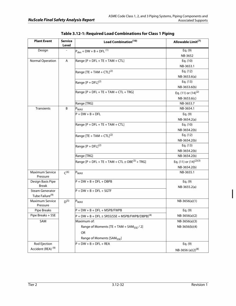
NuScale Final Safety Analysis ReportASME Code Class 1, 2, and 3 Piping Systems, Piping Components and
Associated Supports
Tier 2 3.12-32 Revision 1
Table 3.12-1: Required Load Combinations for Class 1 Piping
Plant Event Service Level
Load Combination(10) Allowable Limit(7)
Design - Pdes + DW + B + DFL (1) Eq. (9)
NB-3652Normal Operation A Range [P + DFL + TE + TAM + CTL] Eq. (10)
NB-3653.1
Range [TE + TAM + CTL](2) Eq. (12)
NB-3653.6(a)
Range [P + DFL](2) Eq. (13)
NB-3653.6(b)Range [P + DFL + TE + TAM + CTL + TRG] Eq. (11) or (14)(2)
NB-3653.6(c)Range [TRG] NB-3653.7
Transients B PMAX NB-3654.1
P + DW + B + DFL Eq. (9)
NB-3654.2(a)Range [P + DFL + TE + TAM + CTL] Eq. (10)
NB-3654.2(b)
Range [TE + TAM + CTL](2) Eq. (12)
NB-3654.2(b)
Range [P + DFL](2) Eq. (13)
NB-3654.2(b)Range [TRG] NB-3654.2(b)
Range [P + DFL + TE + TAM + CTL ± OBE(3) + TRG] Eq. (11) or (14)(2)(3)
NB-3654.2(b)Maximum Service
PressureC(6) PMAX NB-3655.1
Design Basis Pipe Break
P + DW + B + DFL + DBPB Eq. (9)
NB-3655.2(a)Steam Generator
Tube Failure(9)P + DW + B + DFL + SGTF
Maximum Service Pressure
D(5) PMAX NB-3656(a)(1)
Pipe Breaks P + DW + B + DFL + MSPB/FWPB Eq. (9)
NB-3656(a)(2)Pipe Breaks + SSE P + DW + B + DFL ± SRSS(SSE + MSPB/FWPB/DBPB)(4)
SAM Maximum of:
Range of Moments [TE + TAM + SAMSSE / 2]
OR
Range of Moments [SAMSSE]
NB-3656(a)(3)
NB-3656(b)(4)
Rod Ejection Accident (REA) (9)
P + DW + B + DFL + REA Eq. (9)
NB-3656 (a)(2)(8)

NuScale Final Safety Analysis ReportASME Code Class 1, 2, and 3 Piping Systems, Piping Components and
Associated Supports
Tier 2 3.12-33 Revision 1
Pressure Test Test DW + B + H NB-3657
NB-3226DW + B + CLIRT
Notes:
(1) DFL for Service Level A are considered for Design Condition.
(2) Load combination is only applicable for those load sets that do not meet the Eq. (10)
(3) OBE loading is only applicable to the fatigue analysis required by ASME Section III, NB-3650 considering the effects of the PWR environment in accordance with the requirements of RG 1.207 and NUREG/CR-6909. When determining applicability of Eq. (14) for the fatigue evaluation, OBE loading are considered for the load combinations specified for Eqs (10) and (13) also. OBE includes both inertial and SAM combined by absolute sum.
(4) Dynamic loads are combined considering the time phasing of the events in accordance with References RG 1.92 and NUREG-0484.
(5) The rules in NB-3656(b) or ASME III Nonmandatory Appendix F may be used as an alternative to NB-3656(a) to evaluate these conditions independent of other Design and Service Loadings.
(6) If the total number of postulated occurrences for Service Level C conditions result in more than 25 stress cycles having an alternating stress intensity (Salt) greater than the Sa value at 106 cycles determined from the applicable fatigue design curves given in ASME BPVC Section III Mandatory Appendix I, those cycles in excess of 25 stress cycles are included in the fatigue analysis (see NB-3113(b)).
(7) ASME Code equations and the stress limits / acceptance criteria are as defined in the referenced citation from ASME BPVC Section III, Subsection NB.
(8) In accordance with NUREG-0800 Section 15.4.8, Acceptance Criterion 2.
(9) Dynamic load due to SG tube failure or rod ejection accident is negligible.
(10) Applicable loads are defined in Section 3.12.5.3 and Table 3.9-2.
Table 3.12-1: Required Load Combinations for Class 1 Piping (Continued)
Plant Event Service Level
Load Combination(10) Allowable Limit(7)

NuScale Final Safety Analysis ReportASME Code Class 1, 2, and 3 Piping Systems, Piping Components and
Associated Supports
Tier 2 3.12-34 Revision 1
Table 3.12-2: Required Load Combinations for Class 2 & 3 Piping
Plant Event Service Level
Load Combination(11) Allowable Limit(7)
Design Design Pdes + DW + B + DFL(2) Eq. (8)
NC/ND-3652Normal Operation /
TransientsA / B(1) [P + DW + B + DFL] (3) Eq. (9a) or (9b)
NC/ND-3653.1(a) or (b)TE + TAM Eq. (10a)(4)
NC/ND-3653.2(a)Non-Repeated Anchor Movement (Building Settlement, etc.)
Eq. (10b)
NC/ND-3653.2(b)Pdes + DW + B + TE + TAM + DFL Eq. (11)(4)
NC/ND-3653.2(c)Permissible Pressure C PMAX NC/ND-3654.1
Design Basis Pipe Break P + DW + B + DFL + DBPB Eq. (9a) or (9b)
NC/ND-3654.2(a)Steam Generator Tube Failure(9)
P + DW + B + DFL + SGTF
Rod Ejection Accident (REA)(9) D P + DW + B + DFL + REA Eq. (9)
NC/ND -3655(a)(2)(10)
Permissible Pressure D(6)(8) PMAX NC/ND-3655(a)(1)
Pipe Breaks P + DW + B + DFL + MSPB/FWPB Eq. (9a) or (9b)
NC/ND-3655(a)(2)Pipe Breaks + SSE P + DW + B + DFL ± SRSS(SSE + MSPB/FWPB/DBPB)(5)
SAM Maximum of:
Range of Moments [TE + TAM + SAMSSE / 2]
OR
Range of Moments [SAMSSE]
NC/ND-3655(a)(3)
NC/ND-3655(b)(4)
Notes:
(1) Evaluation of OBE loads (both inertia and SAM) is not required for Class 2 & 3 piping.
(2) DFL for Service Level A are considered for Design Condition.
(3) Applicable for Level B only.
(4) Requirements of either Eq. 10a or Eq. 11 are met, not both.
(5) Dynamic loads are combined considering the time phasing of the events in accordance with RG 1.92 and NUREG-0484.
(6) The rules in NC/ND -3655(b) or ASME III Nonmandatory Appendix F may be used as an alternative to NC/ND-3655(a) to evaluate these conditions independent of other Design and Service Loadings.
(7) ASME Code equations and stress limits / acceptance criteria are as defined in the referenced citation from ASME BPVC Section III, Subsections NC or ND as applicable.
(8) For Service Level D, the requirements related to maintaining functional capability which may require piping primary stresses to be limited to Service Level B criteria given in NC/ND-3653.1(a) or (b) are met.
(9) Dynamic load due to SG tube failure or rod ejection accident is negligible.
(10) In accordance with NUREG-0800 Section 15.4.8, Acceptance Criterion 2.
(11) Applicable loads are defined in Section 3.12.5.3 and Table 3.9-2.

NuScale Final Safety Analysis ReportASME Code Class 1, 2, and 3 Piping Systems, Piping Components and
Associated Supports
Tier 2 3.12-35 Revision 1
Table 3.12-3: Required Load Combinations for Class 1, 2, & 3 Supports
Plant Event(1) Service Level Load Combination(2)(10) Allowable Limit(6)(7)
Design Design DW + B + TE + TAM + DFL DesignNormal Operations A DW + B + TE + TAM + DFL Level ATransients B DW + B + TE + TAM + DFL Level B
Transients + OBE(3) B DW + B + TE + TAM + DFL ± OBE(3) -
Design Basis Pipe Break(4) C DW + B + TE + TAM + DFL + DBPB Level C
SG Tube Failure(8) DW + B + TE + TAM + DFL + SGTF
Rod Ejection Accident (REA) (8)(9) D DW + B + TE + TAM + DFL + REA Level C
Main Steam and Feedwater Pipe Breaks
D DW + B + TE + TAM + DFL + MSPB/FWPB Level D
DBPB/MSPB/FWPB + SSE(4) DW + B + TE + TAM + DFL ± SRSS(SSE(4) + MSPB/FWPB/DBPB) (5)
Pressure Test - DW + B TestNotes:
(1) Fatigue analysis of Class 1 supports are evaluated in accordance with the ASME BPVC Section III.
(2) Applicable loads are defined in Section 3.12.5.3.
(3) OBE loading is only applicable to the ASME Section III, NF-3300 fatigue analysis required for Class 1 linear supports subjected to greater than 20,000 cycles of thermal loading, as determined from the detailed piping system analysis. When the USM method of response spectrum analysis is used, OBE includes both inertial and SAM combined by absolute sum. If ISM response spectrum analysis is used, then inertial and SAM are combined by SRSS.
(4) When the USM method of response spectrum analysis is used, SSE includes both inertial and SAM combined by absolute sum. If ISM response spectrum analysis is used, then inertial and SAM are combined by SRSS.
(5) Dynamic loads are combined considering the time phasing of the events in accordance with References RG 1.92 and NUREG-0484.
(6) Stress limits are as defined in NF-3131 of ASME BPVC Section III, Subsection NF for the specified level as applicable to the type of support and class of construction.
(7) For Class 1 linear type and plate-and-shell type supports, the additional stress limit criteria of RG 1.124 and RG 1.130 are met.
(8) Dynamic load due to SG tube failure or Rod Ejection Accident is negligible.
(9) Analyze to level C in accordance with NUREG-0800 SRP Section 15.4.8 Acceptance Criterion 2.
(10) Loads due to friction are considered for applicable loading conditions as described in Section 3.12.6.10.

NuScale Final Safety Analysis Report Threaded Fasteners (ASME Code Class 1, 2, and 3)
Tier 2 3.13-1 Revision 1
3.13 Threaded Fasteners (ASME Code Class 1, 2, and 3)
This section addresses the application of the American Society of Mechanical Engineers (ASME) Boiler and Pressure Vessel Code (BPVC), Section III, Division 1 (Reference 3.13-1), to the design of Class 1, 2, and 3 pressure-retaining threaded fasteners. Threaded fasteners and bolted connections, herein called threaded fasteners unless specified differently, include the bolts, studs, nuts, and washers that are associated with Class 1, 2, and 3 pressure retaining joints.
The selection, design, fabrication, installation and inspection of threaded fasteners in the Class 1, 2 and 3 systems meet the criteria of 10 CFR 50.55a, including 10 CFR 50.55a(b)(4). There are no code cases per Regulatory Guide (RG) 1.84 Revision 36 used in the design of threaded fasteners in Class 1, 2, and 3 systems.
The threaded fastener design complies with General Design Criteria (GDCs) 1, 4, 14, 30 and 31. Further discussion of compliance with the GDCs are provided in this section.
• GDCs 1 and 30 require that structures, systems, and components (SSC) be designed to quality standards commensurate with the importance of the safety function to be performed. GDCs 1 and 30 are met as the bolting design is in conformance with the criteria of ASME BPVC, Section III and RG 1.65 Revision 1 as described below.
• GDC 4 requires that SSC accommodate the effects of, and that they are compatible with, the environmental conditions of normal and accident conditions. GDC 4 is met by protecting the ASME Class 1, 2, and 3 threaded fasteners from the adverse impacts from lubricants and sealants and by using stainless steels or nickel-base alloys that are resistant to boric acid corrosion.
• GDC 14 is met by designing the threaded fasteners to ASME Class 1 criteria.
• GDC 31 is met by conformance with the requirements of 10 CFR 50, Appendix G, which establishes fracture toughness requirements. Thus the probability of a rapid fracture of the threaded fasteners is minimized satisfying the requirements of GDC 31.
10 CFR 50, Appendix B, Criterion XIII, requires that measures be established to control the cleaning of material and equipment to prevent damage or deterioration. RG 1.28 Revision 4 provides quality assurance criteria for cleaning fluid systems and associated components that comply with 10 CFR 50 Appendix B. The design for threaded fasteners meets the cleaning criteria in RG 1.28.
3.13.1 Design Considerations
The design and analysis of pressure boundary threaded fasteners complies with ASME Class 1, 2 and 3 requirements. Class 1 pressure boundary threaded fasteners are designed in accordance with ASME BPVC, Section III (Reference 3.13-1), Subsection NB. Class 2 and 3 threaded fasteners are designed in accordance with Subsection NC and ND requirements, respectively.
3.13.1.1 Materials Selection
ASME Code Section III provides acceptable standards for selecting threaded fastener material identified in ASME Code, section II (Reference 3.13-2). ASME Section II (Reference 3.13-2) provides the material properties for threaded fasteners for ASME

NuScale Final Safety Analysis Report Threaded Fasteners (ASME Code Class 1, 2, and 3)
Tier 2 3.13-2 Revision 1
Class 1, 2, and 3 applications. The applicable criteria used for material selection for ASME Class 1, 2, and 3 threaded fasteners are listed in Table 3.13-1. Materials used for the threaded fasteners are selected for the associated environmental conditions for the lifetime of the plant. Only proven materials for the specific application and environment are used. Bolting material selection satisfies applicable requirements of EPRI TR-101108, "Boric Acid Corrosion Evaluation (BACE) Program, Phase - Task 1 Report," (Reference 3.13-6), EPRI NP-5985, "Boric Acid Corrosion of Carbon and Low-Alloy Steel Pressure-Boundary Components in PWRs," (Reference 3.13-7), and EPRI NP-5558-SL, "Boric Acid Application Guidelines for Intergranular Corrosion Inhibition," (Reference 3.13-8).
The reactor pressure vessel closure studs, nuts, and washers use SB-637 UNS N07718 (Alloy 718), instead of low alloy steels such a SA-540 Grade B23 or B24. The diameter of Alloy 718 threaded fasteners is 6 inches or less. The selection of Alloy 718 over traditional low alloy steels is to prevent general corrosion when the bolting is submerged during plant startup and shutdown process. Because of its resistance to general corrosion, the concerns addressed by RG 1.65 position 2(b) do not apply to Alloy 718. Alloy 718 is an austenitic, precipitation hardened, nickel-base alloy permitted for bolting materials by ASME BPVC Code Section lll (Reference 3.13-1), Subsection NB-2128.
Being a nonferrous material, the fracture toughness requirements of ASME B&PV Code, Section III (Reference 3.13-1), Subsection NB-2311 exempts Alloy 718 from fracture toughness test requirement in NB-2300. The minimum required room temperature yield strength of SB-637 Alloy 718 is 150 ksi, exceeding the 150 ksi maximum limit in RG 1.65 position 1(a)(i). Because Alloy 718 is nonferrous, it is not subject to the fracture toughness requirements in 10 CFR 50 Appendix G or RG 1.65. Hence, the concern addressed by RG 1.65 position 1(a)(i) is not applicable to Alloy 718.
Alloy 718 is resistant to stress corrosion cracking (SCC) when exposed to high temperature primary reactor coolant, although limited SCC was observed inside reactor vessel internals (Reference 3.13-3). However, SCC is unlikely for reactor vessel closure bolting because it will be submerged at a much lower temperature than reactor coolant temperature. In order to improve SCC resistance, the solution treatment temperature range prior to precipitation hardening treatment is restricted to 1800°F to 1850°F. Except for the more restrictive solution temperature range, the heat treatment is identical to SB-637 UNS N07718. This heat treatment process provides better resistance to SCC and is within the limits of ASME Section II (Reference 3.13-2) material specification for Alloy 718.
This same heat retreatment for the mitigation of SCC is applied to Alloy 718 threaded fasteners in all environments and applications where they are used in the NuScale design associated with Class 1, 2, and 3 pressure retaining joints. This includes Alloy 718 applications in low flow areas and low temperature systems.
Consistent with RG 1.65, lubricant will be selected in accordance with the guidance in NUREG-1339 (Reference 3.13-4). Lubricants containing molybdenum sulfide are prohibited. Based on the above discussion, Alloy 718 bolting material for closure is in compliance with RG 1.65 requirements except for the requirements not applicable to Alloy 718 bolting as described above.

NuScale Final Safety Analysis Report Threaded Fasteners (ASME Code Class 1, 2, and 3)
Tier 2 3.13-3 Revision 1
3.13.1.2 Special Materials Fabrication Processes and Controls
The criteria for mechanical property testing of threaded fasteners complies with the requirements of ASME BPVC, Section II (Reference 3.13-2), Part A and Part B as noted in Table 3.13-1. Threaded fastener materials are chosen from proven materials for the specific application and environment and are used after evaluation of the potential for degradation, including galvanic corrosion and SCC. The bolting materials selected for the ASME Class 1, 2 and 3 threaded fasteners are discussed in Sections 4.5, 5.2, 5.3, 6.1 and 6.2.
Fabrication and examination of threaded fasteners are performed in accordance with the criteria in Table 3.13-1 for ASME Code Class 1, 2 and 3 systems.
Lubricants used for the threaded fasteners covered by this section will be selected in accordance with the guidance in NUREG-1339 (Reference 3.13-4) to avoid galvanic corrosion and SCC. Lubricants containing molybdenum sulfide are prohibited.
3.13.1.3 Fracture Toughness Requirements for Threaded Fasteners Made from Ferritic Materials
The pressure-retaining Class 1, 2 and 3 components made of ferritic material meet the requirements of ASME BPVC, Section III (Reference 3.13-1), Subsections NB-2300, NC-2300 and ND-2300 respectively (Table 3.13-1). For pressure-retaining components of the reactor coolant pressure boundary, the requirements are supplemented by the additional requirements set forth in 10 CFR 50, Appendix G.
3.13.1.4 Pre-Service Inspection Requirements
Pressure boundary Class 1, 2 and 3 threaded fasteners are examined in accordance with ASME BPVC, Section XI (Reference 3.13-5), Subsections IWB-2200, IWC-2200 and IWD-2200 respectively for pre-service inspection.
3.13.1.5 Certified Material Test Reports (QA Records)
All Pressure-retaining Class 1, 2 and 3 threaded fasteners are certified in accordance with Subsection NCA-3861 and Subsection NCA-3862 and are furnished with certified material test reports (CMTRs) in accordance with the criteria of ASME BPVC, Section III (Reference 3.13-1) Subsections NB-2130, NC-2130 and ND-2130, respectively.
Material identification is required for all Class 1, 2 and 3 threaded fasteners per ASME BPVC, Section III (Reference 3.13-1), Subsections NB-2150, NC-2150, ND-2150, respectively. CMTRs for ASME Section III Class 1, 2, and 3 threaded fasteners will be retained in accordance with 10 CFR 50.71.
3.13.2 Inservice Inspection Requirements
Inservice Inspection for ASME Class 1, 2, and 3 threaded fasteners is in accordance with the ASME BPVC, Section XI (Reference 3.13-5) (see Table 3.13-2), as required by 10 CFR 50.55a, except where specific written relief has been granted by the NRC.

NuScale Final Safety Analysis Report Threaded Fasteners (ASME Code Class 1, 2, and 3)
Tier 2 3.13-4 Revision 1
COL Item 3.13-1: A COL applicant that references the NuScale Power Plant design certification will provide an in-service inspection program for ASME Class 1, 2 and 3 threaded fasteners. The program will identify the applicable edition and addenda of ASME Boiler and Pressure Vessel Code, Section XI and ensure compliance with 10 CFR 50.55a.
3.13.3 References
3.13-1 American Society of Mechanical Engineers, Boiler and Pressure Vessel Code, 2013 Edition, Section III, "Rules for Construction of Nuclear Facility Components," American Society of Mechanical Engineers.
3.13-2 American Society of Mechanical Engineers, Boiler and Pressure Vessel Code, 2013 Edition, Section II, "Materials," American Society of Mechanical Engineers.
3.13-3 A. R. McIlree, "Degradation of High Strength Austenitic Alloys X-750, 718 and A286 in Nuclear Power Systems," 1st International Symposium on Environmental Degradation of Materials in Nuclear Power Systems - Water Reactors, NACE, 1984.
3.13-4 U.S. Nuclear Regulatory Commission, “Resolution of Generic Safety Issue 29: Bolting Degradation or Failure in Nuclear Power Plants,” NUREG-1339, June 1990.
3.13-5 American Society of Mechanical Engineers, Boiler and Pressure Vessel Code, 2013 Edition, Section XI, "Rules for Inservice Inspection of Nuclear Power Plant Components," American Society of Mechanical Engineers.
3.13-6 Electric Power Research Institute, “Boric Acid Corrosion Evaluation (BACE) Program, Phase - Task 1 Report,” TR-101108, Palo Alto, CA, December 1993.
3.13-7 Electric Power Research Institute, “Boric Acid Corrosion of Carbon and Low Alloy Steel Pressure Boundary Components in PWRs,” NP- 5985, Palo Alto, CA., August 1988.
3.13-8 Electric Power Research Institute, “Boric Acid Application Guidelines for Intergranular Corrosion Inhibition,” NP-5558, Palo Alto, CA, December 1987.

NuScale Final Safety Analysis Report Threaded Fasteners (ASME Code Class 1, 2, and 3)
Tier 2 3.13-5 Revision 1
Table 3.13-1: ASME BPV Code Section III Criteria for Selection and Testing of Bolted Materials
Code Category ASME Class 1 Criteria ASME Class 2 Criteria ASME Class 3 CriteriaMaterial Selection NCA-1220 and NB-2128 NCA-1220 and NC-2128 NCA-1220 and ND-2128
Material test coupons and specimens for ferritic steel material (tensile test criteria)
Heat Treatment Criteria NB-2210 NC-2210 ND-2210Test couponsrequirementsbolting and studing materials
NB-2221NB-2224
NC-2221NC-2224.3
ND-2221ND-2224.3
Fracture toughness requirements
Materials to be impact tested
NB-2311 NC-2311 ND-2311
Types of impact test NB-2321 NC-2321 ND-2321Test coupons NB-2322 NC-2322 ND-2322Acceptance standards NB-2333 NC-2332.3 ND-2333Number of impact tests necessary
NB-2345 NC-2345 ND-2345
Retesting NB-2350 NC-2352 ND-2352Calibration of test equipment
NB-2360 NC-2360 ND-2360
Examination criteria for bolts, studs, and nuts NB-2580 NC-2580 ND-2580Certified material test report criteria NCA-3860 NCA-3860 NCA-3860Note 1: Section III paragraphs listed in this table represent those specified in the 2013 Edition of Section III.

NuScale Final Safety Analysis Report Threaded Fasteners (ASME Code Class 1, 2, and 3)
Tier 2 3.13-6 Revision 1
Table 3.13-2: ASME BPV Code Section XI Examination Categories for Inservice Inspections of Mechanical Joints in ASME Code Class 1, 2, and 3 Systems that are
Secured by Threaded Fasteners
Code Category ASME Class 1 Criteria ASME Class 2 Criteria ASME Class 3 CriteriaSpecific bolting inspection Table IWB-2500-1 Exam. Cat.
B-G-1 for bolting greater that 2 inches in diameter
Table IWC-2500-1, Exam. Cat. C-D for bolting greater than 2 inches in diameter
Not Applicable - Currently there are no examination categories that correspond to those that exist for ASME Class 1 and 2 bolting.
Table 1WB-2500-1, Exam. Cat. B-G-2 for bolting less than or equal to 2 inches in diameter
System pressure tests Table IWB-2500-1, Exam. Cat. B-P
Table IWC-2500-1, Exam. Cat. C-H
Table IWD-2500-1, Exam. Cat. D-B
Note 1: Section XI paragraphs listed in this table represent those specified in the 2013 Edition of Section XI.