preliminary - gomeasure3dgomeasure3d.com/.../2014/02/microscan-3d-manual-preliminary.pdf · 2 1a...
TRANSCRIPT
Manual MicroScan-3D
RSI GmbH 61440 Oberursel
Germany Phone: +0049(0)6172-934090
www.microscan-3d.com
update.microscan-3d.com [email protected]
Preliminary
1
Content:
1 Getting started a System Requirements 2 b Licensing 2 c Package Contents 3 d Hardware installation 4 e Software / Driver installation 5 f Home position 6 2 Scan Phase a Connect / Disconnect MicroScan 7 b Scanning 8 c Adjust “ 9 d Calibrate” 10 e New Scan 11 f Delete last sweep 11 g General tools 11 3 Sweep Phase a Register object 14 b Merge objects 14 c Register sweeps 15 d Generate pointcloud 15 e Generate mesh 15 f Delete sweeps 16 4 Vertex Phase a Detect noise 16 b Sample pointcloud 17 c Smooth pointcloud 17 5 Mesh Phase a Triangulate pointcloud 2D / 3D 19 b Smooth 20 c Decimate 20 d Fill holes 21 e Detect Triangles / Cluster 21 f Register meshes 22 g Merge meshes 22

2
1a System requirements for Microscan Tools
In order to run properly the computer running Microscan Tools should satisfy at least the following specs:
• A CPU of at least 2 Ghz • Minimum of 700 MB of RAM • USB Port (for the Microscribe) • IEEE1394 (Firewire) Port (either 4 or 6 pins) • An OpenGL accelerated graphics card • Windows XP
1b Licensing
Licensing can be done in 2 ways.
1. License File - the license file has to be placed in the "/license" subdirectory of the Microscan Tools installation path (usually c:/program files/microscan tools/license"). You should obtain the license file from your vendor. There are 2 types of license files.
o A license file, which will only permit you using the software when a specific Microscan is connected to the computer, The license file will then have the form of: licenseF.lic.
o A license file, which locks the license to a specific computer. The computer is identified by its MAC address. The license file will then have the form of: licenseM.lic.
2. By a Hardware Dongle - plug the Dongle into your USB port and install the drivers.
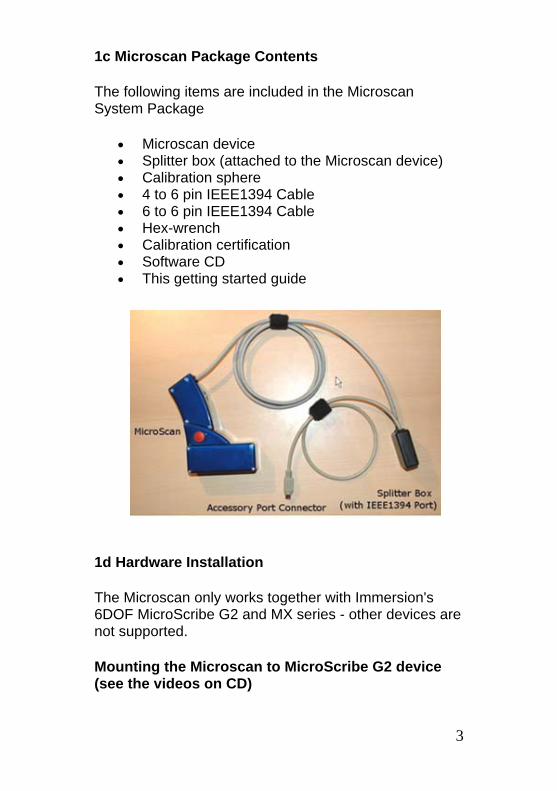
1c Microscan Package Contents
The following items are included in the Microscan System Package
• Microscan device • Splitter box (attached to the Microscan device) • Calibration sphere • 4 to 6 pin IEEE1394 Cable • 6 to 6 pin IEEE1394 Cable • Hex-wrench • Calibration certification • Software CD • This getting started guide
1d Hardware Installation
The Microscan only works together with Immersion's 6DOF MicroScribe G2 and MX series - other devices are not supported.
Mounting the Microscan to MicroScribe G2 device (see the videos on CD)
3
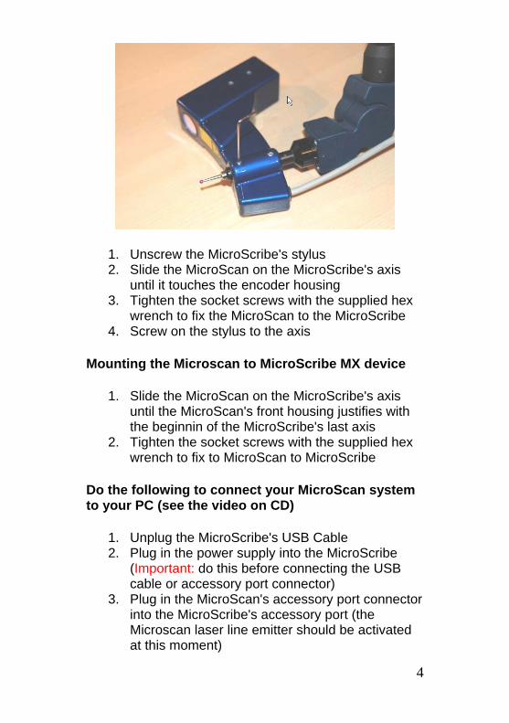
1. Unscrew the MicroScribe's stylus 2. Slide the MicroScan on the MicroScribe's axis
until it touches the encoder housing 3. Tighten the socket screws with the supplied hex
wrench to fix the MicroScan to the MicroScribe 4. Screw on the stylus to the axis
Mounting the Microscan to MicroScribe MX device
1. Slide the MicroScan on the MicroScribe's axis until the MicroScan's front housing justifies with the beginnin of the MicroScribe's last axis
2. Tighten the socket screws with the supplied hex wrench to fix to MicroScan to MicroScribe
Do the following to connect your MicroScan system to your PC (see the video on CD)
1. Unplug the MicroScribe's USB Cable 2. Plug in the power supply into the MicroScribe
(Important: do this before connecting the USB cable or accessory port connector)
3. Plug in the MicroScan's accessory port connector into the MicroScribe's accessory port (the Microscan laser line emitter should be activated at this moment)
4
5
4. Connect the MicroScan's splitter box with the supplied IEEE1394 cable to your computer's IEEE1394 port
5. Connect the MicroScribe to your PC with the USB cable supplied with your MicroScribe
1e Software / Microscan Driver Installation
After setting up and connecting the Microscan do the following to install the MicroScan driver.
1. Open the Windows Device Manager (Start -> Control Panel -> System -> Device Manager)
2. In the device tree unfold the "Imaging devices" node
3. Right click on "1394 Imaging device" and select "Update Driver..."
4. If Windows asks to connect to the Windows Update Server select "No, not this time" (SP2 only)
5. On the next window select "Install from a list or specific location"
6. On the next window select "Don't search, I will choose the driver to install"
7. On the next window select "Have Disk" 8. Point the file selection dialog to "driver"
subdirectory of your MicroScan installation directory and select the "pgrcam.inf" file (usually c:/program files/microscan/driver)
9. When asked for the device name select "PGR Camera"
10. The device should now be listed as "PGR Camera" in the Windows Device Manager
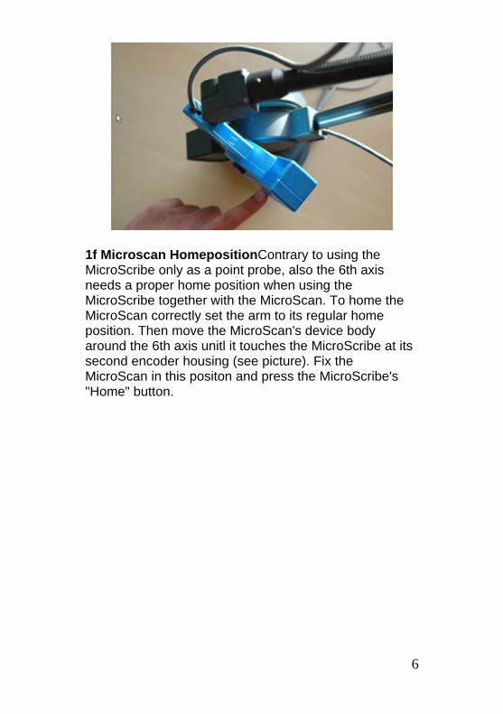
1f Microscan HomepositionContrary to using the MicroScribe only as a point probe, also the 6th axis needs a proper home position when using the MicroScribe together with the MicroScan. To home the MicroScan correctly set the arm to its regular home position. Then move the MicroScan's device body around the 6th axis unitl it touches the MicroScribe at its second encoder housing (see picture). Fix the MicroScan in this positon and press the MicroScribe's "Home" button.
6
2 Scan Phase
2a Connect Microscan
Use this button to connect the Microscan to the software. In order for this to work you need a calibration file in the calibration subdirectory of the Microscan Tools installation directory. Usually this is c:\program files\microscan tools\calibration (if the directory doesn't exist, create it and place the calibration file in it). The calibration file is usually shipped on the Microscan Tools installation CD. After a successfull connection the Microscan sidebar will appear on the screen.
The sidebar gives information about the Microscan's Status. After connecting the Microscan it needs approximately 5 seconds to synchronize to the Microscribe. The status indicator will then turn to "Ready" which indicates that the Microscan is in idle state and ready to capture data.
In the black window you can see a preview of the detected profile. Use this to orient yourself around the scanning part and to check if the Microscan sees what you expect it to see.
The Sweeps field shows the current number of sweeps in the scan target.
The Scan Range radio buttons allow you to switch between the 2 scan ranges.
2a Disconnect Microscan
This button disconnects the Microscan and the software is ready for postprocessing. 7
8
2b Scanning / Capturing Data Idle Mode After successfully connecting, the Microscan is in idle mode. During idle mode one can observe a red plane on the screen. This plane represents the Microscan's sensor range. If the laser beam hits an object within the sensor range, this objects profile is also displayed on the screen. This functionality gives the user visual feedback on where the Microscan is located in the working space and which objects are within its sensor range. Capturing Data If the user clicks on the Microscan's button, the program starts capturing data. The representation of the sensor range (red plane) disappears and a visualization of the captured data is rendered. To stop capturing the Microscan's button has to be clicked again - the Microscan will then return to idle mode. The data captured in one session (between start and stop of capturing) is referred to as a "Sweep". The best way of capturing data is, to move the sensor along a straight line and to stop scanning when the end of the line is reached. The software automatically stops capturing when the user makes an odd movement with the Microscan (like going zikzak or moving too slow/fast). Using Microscan as a Camera If the user holds the Microscan's button during idle mode, the Microscan acts as virtual camera which allows the user to view the scanned data from different directions.This is useful to find out which parts of the objects surface haven't been scanned yet.
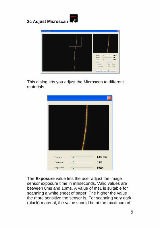
2c Adjust Microscan
This dialog lets you adjust the Microscan to different materials.
The Exposure value lets the user adjust the image sensor exposure time in miliseconds. Valid values are between 0ms and 10ms. A value of ms1 is suitable for scanning a white sheet of paper. The higher the value the more sensitive the sensor is. For scanning very dark (black) material, the value should be at the maximum of
9
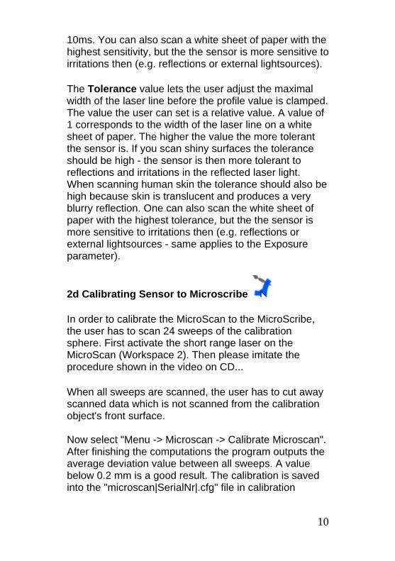
10ms. You can also scan a white sheet of paper with the highest sensitivity, but the the sensor is more sensitive to irritations then (e.g. reflections or external lightsources).
The Tolerance value lets the user adjust the maximal width of the laser line before the profile value is clamped. The value the user can set is a relative value. A value of 1 corresponds to the width of the laser line on a white sheet of paper. The higher the value the more tolerant the sensor is. If you scan shiny surfaces the tolerance should be high - the sensor is then more tolerant to reflections and irritations in the reflected laser light. When scanning human skin the tolerance should also be high because skin is translucent and produces a very blurry reflection. One can also scan the white sheet of paper with the highest tolerance, but the the sensor is more sensitive to irritations then (e.g. reflections or external lightsources - same applies to the Exposure parameter).
2d Calibrating Sensor to Microscribe
In order to calibrate the MicroScan to the MicroScribe, the user has to scan 24 sweeps of the calibration sphere. First activate the short range laser on the MicroScan (Workspace 2). Then please imitate the procedure shown in the video on CD...
When all sweeps are scanned, the user has to cut away scanned data which is not scanned from the calibration object's front surface. Now select "Menu -> Microscan -> Calibrate Microscan". After finishing the computations the program outputs the average deviation value between all sweeps. A value below 0.2 mm is a good result. The calibration is saved into the "microscan|SerialNr|.cfg" file in calibration
10
directory on your MicroScan software installation (usually c:\program files\MicroScan\calibration).
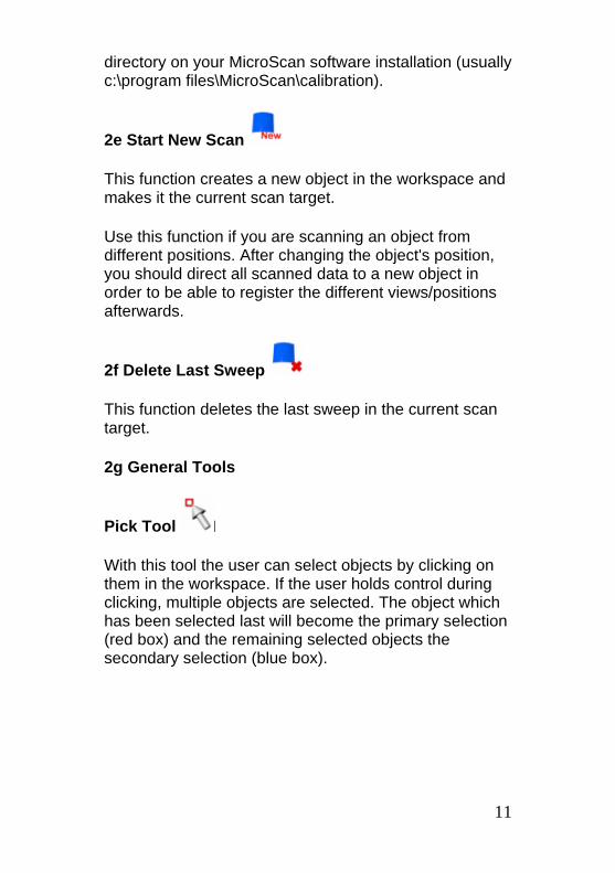
2e Start New Scan
This function creates a new object in the workspace and makes it the current scan target.
Use this function if you are scanning an object from different positions. After changing the object's position, you should direct all scanned data to a new object in order to be able to register the different views/positions afterwards.
2f Delete Last Sweep
This function deletes the last sweep in the current scan target.
2g General Tools
Pick Tool
With this tool the user can select objects by clicking on them in the workspace. If the user holds control during clicking, multiple objects are selected. The object which has been selected last will become the primary selection (red box) and the remaining selected objects the secondary selection (blue box).
11
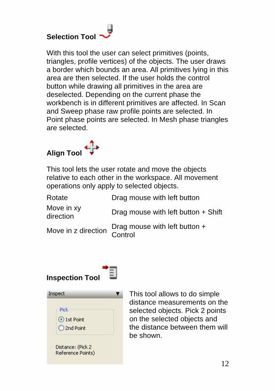
Selection Tool
With this tool the user can select primitives (points, triangles, profile vertices) of the objects. The user draws a border which bounds an area. All primitives lying in this area are then selected. If the user holds the control button while drawing all primitives in the area are deselected. Depending on the current phase the workbench is in different primitives are affected. In Scan and Sweep phase raw profile points are selected. In Point phase points are selected. In Mesh phase triangles are selected.
Align Tool
This tool lets the user rotate and move the objects relative to each other in the workspace. All movement operations only apply to selected objects. Rotate Drag mouse with left button Move in xy direction Drag mouse with left button + Shift
Move in z direction Drag mouse with left button + Control
Inspection Tool
12
This tool allows to do simple distance measurements on the selected objects. Pick 2 points on the selected objects and the distance between them will be shown.
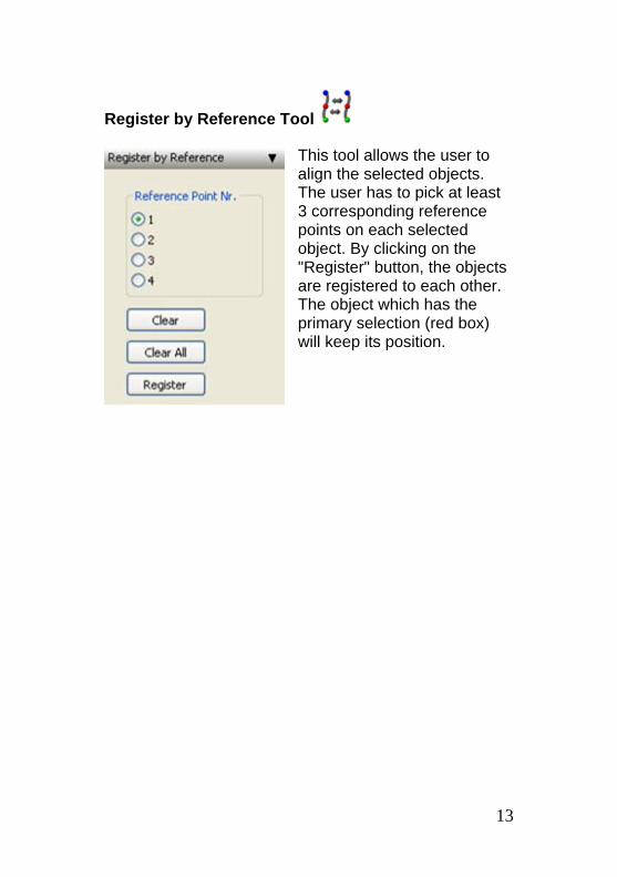
Register by Reference Tool
This tool allows the user to align the selected objects. The user has to pick at least 3 corresponding reference points on each selected object. By clicking on the "Register" button, the objects are registered to each other. The object which has the primary selection (red box) will keep its position.
13
3 Sweep Phase
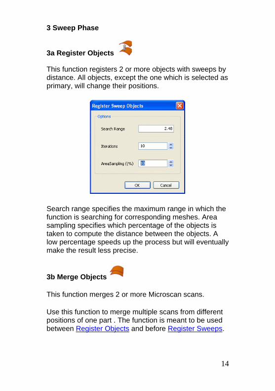
3a Register Objects
This function registers 2 or more objects with sweeps by distance. All objects, except the one which is selected as primary, will change their positions.
Search range specifies the maximum range in which the function is searching for corresponding meshes. Area sampling specifies which percentage of the objects is taken to compute the distance between the objects. A low percentage speeds up the process but will eventually make the result less precise.
3b Merge Objects
This function merges 2 or more Microscan scans.
Use this function to merge multiple scans from different positions of one part . The function is meant to be used between Register Objects and before Register Sweeps.
14
3c Register Sweeps
This function registers each sweep to all other sweeps in an object by distance.
Search range specifies the maximum range in which the function is searching for corresponding sweeps. This functions minimizes the deviation between sweeps and improves the quality of the final mesh.
3d Generate Pointcloud
This function converts the scanned raw points into a pointcloud.
You can specify a reduction factor, by which the raw data points are reduced. A factor of 2 means that only each second raw point is transfered into the pointcloud (resp. each 3rd, 4th....).
You can also choose to reduce noise by profile registration. During this process, each profile of each sweep is registered seperately to all other sweeps by distance. The resulting pointcloud should further be processed by the vertex and mesh tools (usually a pointcloud smoothing first and then a 3d triangulation).
3e Generate Mesh
This function transfers the rendering mesh of the sweeps into an editable mesh.
15
3f Delete Sweeps
This function deletes the sweep data of an object.
This function is usually used after converting the sweep data into a pointcloud - the sweeps are not needed any more and can be removed to save memory.
4 Vertex Phase
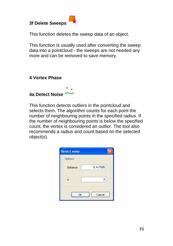
4a Detect Noise
This function detects outliers in the pointcloud and selects them. The algorithm counts for each point the number of neighbouring points in the specified radius. If the number of neighbouring points is below the specified count, the vertex is considered an outlier. The tool also recommends a radius and count based on the selected object(s).
16
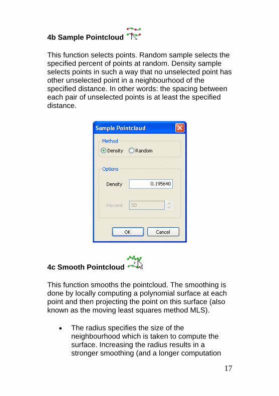
4b Sample Pointcloud
This function selects points. Random sample selects the specified percent of points at random. Density sample selects points in such a way that no unselected point has other unselected point in a neighbourhood of the specified distance. In other words: the spacing between each pair of unselected points is at least the specified distance.
4c Smooth Pointcloud
This function smooths the pointcloud. The smoothing is done by locally computing a polynomial surface at each point and then projecting the point on this surface (also known as the moving least squares method MLS).
• The radius specifies the size of the neighbourhood which is taken to compute the surface. Increasing the radius results in a stronger smoothing (and a longer computation
17
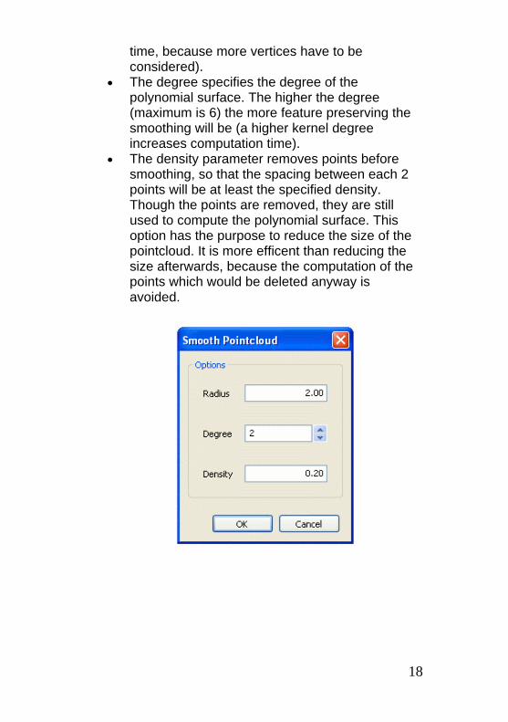
time, because more vertices have to be considered).
• The degree specifies the degree of the polynomial surface. The higher the degree (maximum is 6) the more feature preserving the smoothing will be (a higher kernel degree increases computation time).
• The density parameter removes points before smoothing, so that the spacing between each 2 points will be at least the specified density. Though the points are removed, they are still used to compute the polynomial surface. This option has the purpose to reduce the size of the pointcloud. It is more efficent than reducing the size afterwards, because the computation of the points which would be deleted anyway is avoided.
18
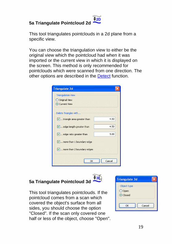
5a Triangulate Pointcloud 2d
This tool triangulates pointclouds in a 2d plane from a specific view.
You can choose the triangulation view to either be the original view which the pointcloud had when it was imported or the current view in which it is displayed on the screen. This method is only recommended for pointclouds which were scanned from one direction. The other options are described in the Detect function.
5a Triangulate Pointcloud 3d
This tool triangulates pointclouds. If the pointcloud comes from a scan which covered the object's surface from all sides, you should choose the option "Closed". If the scan only covered one half or less of the object, choose "Open".
19
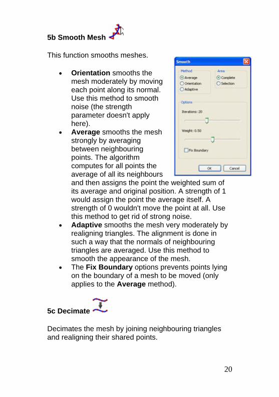
5b Smooth Mesh
This function smooths meshes.
• Orientation smooths the mesh moderately by moving each point along its normal. Use this method to smooth noise (the strength parameter doesn't apply here).
• Average smooths the mesh strongly by averaging between neighbouring points. The algorithm computes for all points the average of all its neighbours and then assigns the point the weighted sum of its average and original position. A strength of 1 would assign the point the average itself. A strength of 0 wouldn't move the point at all. Use this method to get rid of strong noise.
• Adaptive smooths the mesh very moderately by realigning triangles. The alignment is done in such a way that the normals of neighbouring triangles are averaged. Use this method to smooth the appearance of the mesh.
• The Fix Boundary options prevents points lying on the boundary of a mesh to be moved (only applies to the Average method).
5c Decimate
Decimates the mesh by joining neighbouring triangles and realigning their shared points.
20
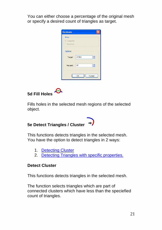
You can either choose a percentage of the original mesh or specify a desired count of triangles as target.
5d Fill Holes
Fills holes in the selected mesh regions of the selected object.
5e Detect Triangles / Cluster
This functions detects triangles in the selected mesh. You have the option to detect triangles in 2 ways:
1. Detecting Cluster 2. Detecting Triangles with specific properties.
Detect Cluster
This functions detects triangles in the selected mesh.
The function selects triangles which are part of connected clusters which have less than the speciefied count of triangles.
21
Detect Triangles
This functions detects triangles in the selected mesh.
1. Area selects triangles which are greater than the size specified by the user. With the spin control the user can specify a ratio of the selected mesh's average triangle size as size.
2. Edge selects triangles where one of its edges is longer than the length specified by the user. With the spin control the user can specify a ratio of the selected mesh's average edge length as length.
3. Ratio selects triangles which aspect ratio is greater than the ratio specified by the user. The aspect ratio is defined as the ratio between the longest edge and the height of the triangle (with the longest edge as base for the height).
5f Register Meshes
This function registers 2 or more objects by distance. All objects, except the one which is selected as primary, will change their positions.
Search range specifies the maximum range in which the function is searching for corresponding meshes. Area sampling specifies which percentage of the mesh is taken to compute the distance between the meshes. A low percentage speeds up the process but will eventually make the result less precise.
5g Merge Meshes
Merges the selected objects together.
22
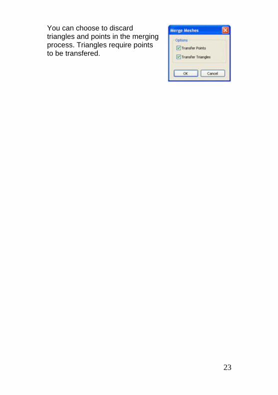
You can choose to discard triangles and points in the merging process. Triangles require points to be transfered.
23