preliminary detailed design review - edge
TRANSCRIPT
Preliminary Detailed Design Review
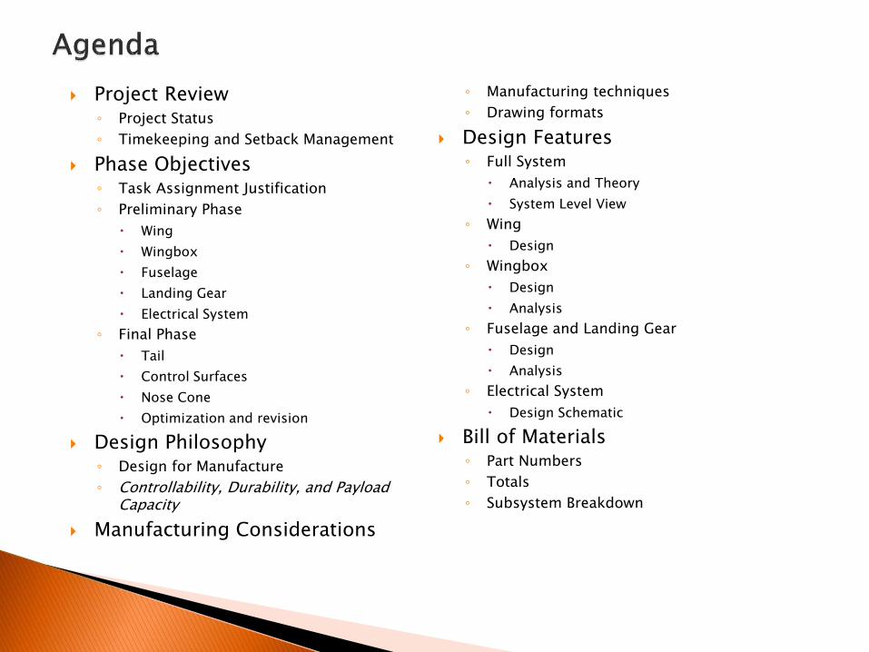
Project Review◦ Project Status
◦ Timekeeping and Setback Management
Phase Objectives◦ Task Assignment Justification
◦ Preliminary Phase
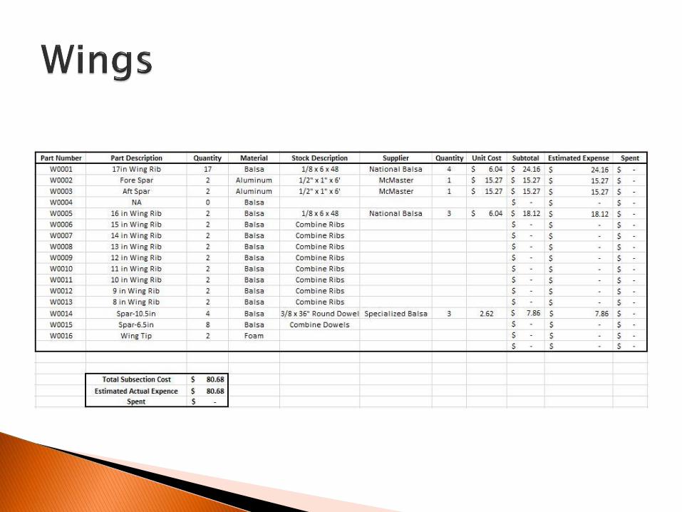
Wing
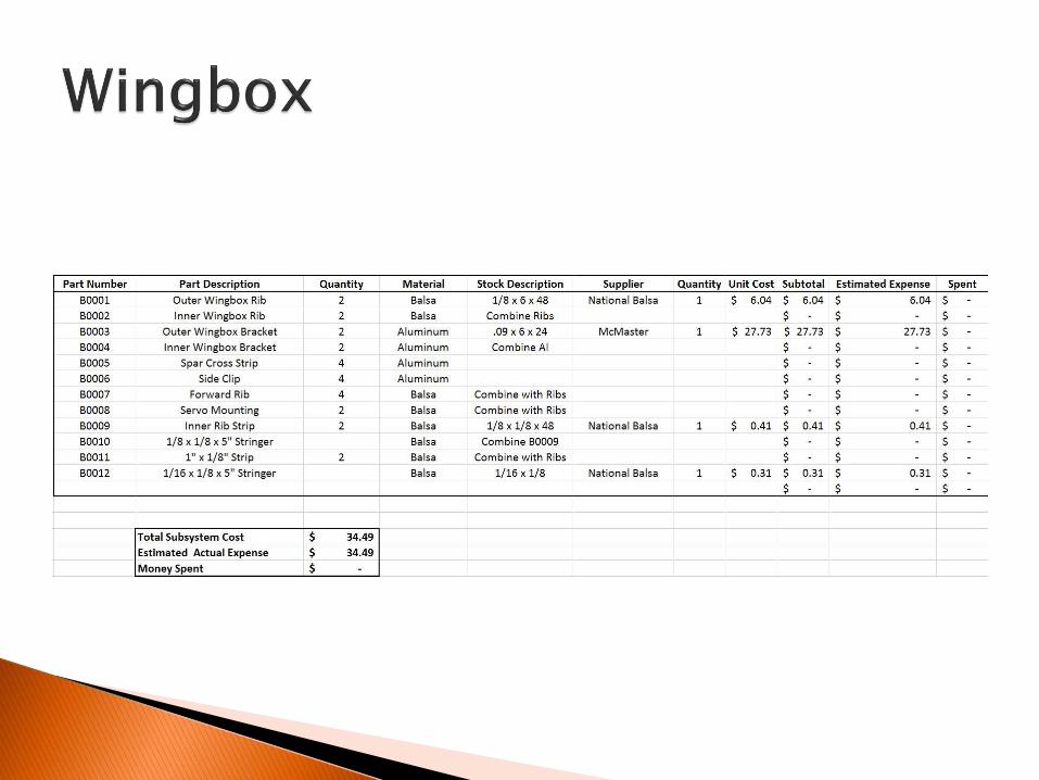
Wingbox
Fuselage
Landing Gear
Electrical System
◦ Final Phase
Tail
Control Surfaces
Nose Cone
Optimization and revision
Design Philosophy◦ Design for Manufacture
◦ Controllability, Durability, and Payload Capacity
Manufacturing Considerations
◦ Manufacturing techniques
◦ Drawing formats
Design Features◦ Full System
Analysis and Theory
System Level View
◦ Wing
Design
◦ Wingbox
Design
Analysis
◦ Fuselage and Landing Gear
Design
Analysis
◦ Electrical System
Design Schematic
Bill of Materials◦ Part Numbers
◦ Totals
◦ Subsystem Breakdown

Project Status, Timekeeping and Setback Management
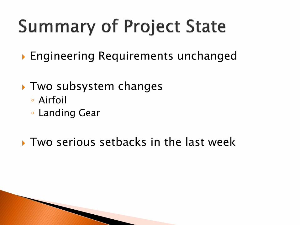
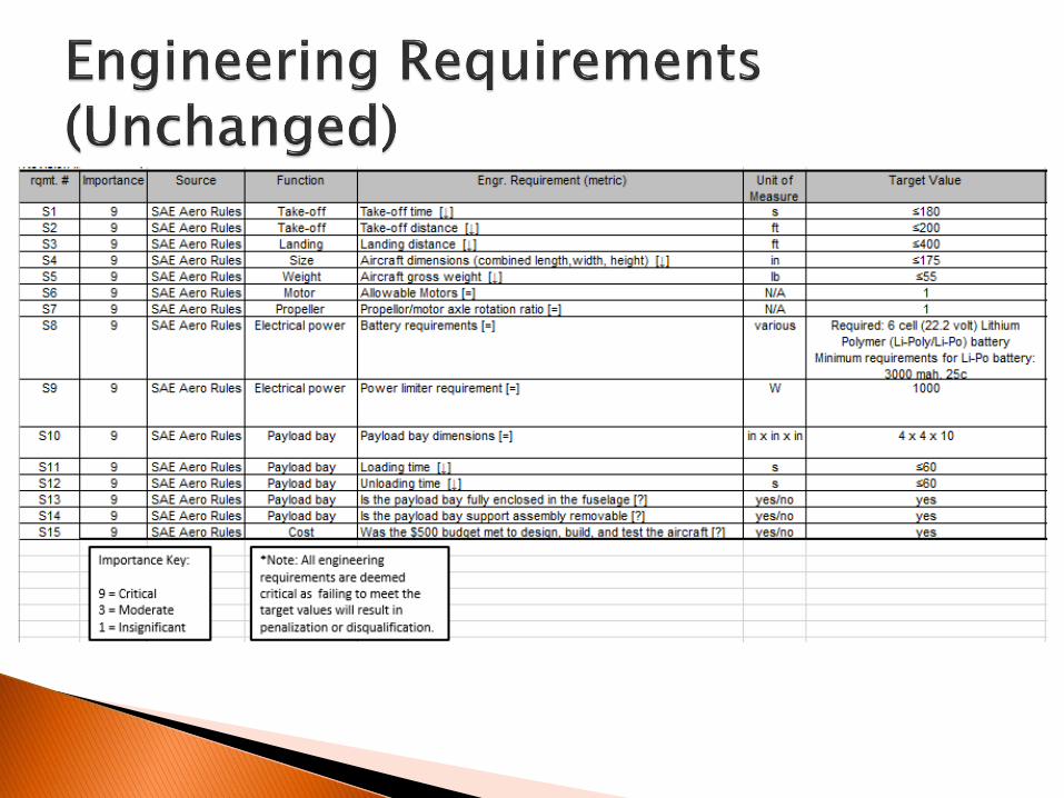
Engineering Requirements unchanged
Two subsystem changes◦ Airfoil
◦ Landing Gear
Two serious setbacks in the last week
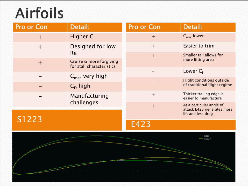
S1223E423
Pro or Con Detail:
+ Higher Cl
+ Designed for low Re
+ Cruise α more forgivingfor stall characteristics
- Cmac very high
- CD high
- Manufacturingchallenges
Pro or Con Detail:
+ Cmac lower
+ Easier to trim
+ Smaller tail allows for more lifting area
- Lower Cl
- Flight conditions outside of traditional flight regime
+ Thicker trailing edge is easier to manufacture
+ At a particular angle of attack E423 generates more lift and less drag
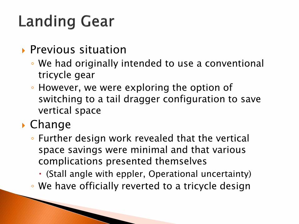
Previous situation◦ We had originally intended to use a conventional
tricycle gear
◦ However, we were exploring the option of switching to a tail dragger configuration to save vertical space
Change◦ Further design work revealed that the vertical
space savings were minimal and that various complications presented themselves
(Stall angle with eppler, Operational uncertainty)
◦ We have officially reverted to a tricycle design
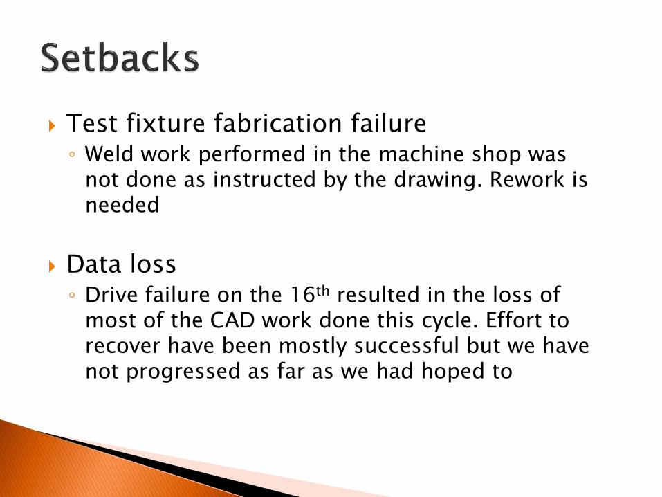
Test fixture fabrication failure◦ Weld work performed in the machine shop was
not done as instructed by the drawing. Rework is needed
Data loss◦ Drive failure on the 16th resulted in the loss of
most of the CAD work done this cycle. Effort to recover have been mostly successful but we have not progressed as far as we had hoped to

Test fixture needed to verify thrust equations
Welds not performed as indicated on drawing◦ Part excessively heated: warped as a
result
◦ Part not assembled properly prior to welding: holes do not line up correctly
◦ Weld not properly centered, access to an internal bolt hole is obstructed
Assessment of feasibility of repairs vs. starting over delayed by other obligations

Efforts to recover the data were unsuccessful due to how dramatic the storage hardware failed.
Edge remains unfriendly to solidworksassemblies
Current plan is to make more effective backups
We have remade what was lost and are now at 80% of where we had hoped to be at this time prior to the failure

Revised Gantt ChartIn the light of recent setbacks and
success ahead of schedule we have adjusted our schedule. Available on
edge in better resolution.
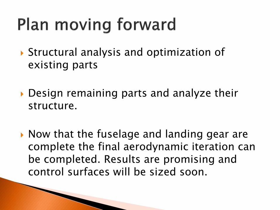
Structural analysis and optimization of existing parts
Design remaining parts and analyze their structure.
Now that the fuselage and landing gear are complete the final aerodynamic iteration can be completed. Results are promising and control surfaces will be sized soon.

Long Term Testing PlanAt the present we have identified 5 tests that will
need to be performed. Three are in place to satisfy the engineering requirements. The other two are
to verify the analysis.

Overview of objectives for content covered in this review and that upcoming goals

The major objective was to design as much of the aircraft as possible to leave time for revision in the next phase.
Priority was given to structures which would influence other structures.
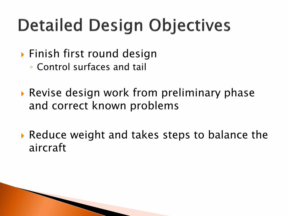
Finish first round design◦ Control surfaces and tail
Revise design work from preliminary phase and correct known problems
Reduce weight and takes steps to balance the aircraft

Discussion of methodology and design decisions not related to analysis

Laser cut wood parts and waterjet cut aluminum◦ Accurate and quick operations to manufacture
◦ Assembly not substantially easier or harder
◦ Requires that we make ‘flat’ parts
Minimize welding◦ Experiences with welded parts in the machine shop
do not inspire confidence in the quality of our parts, so we are attempting to avoid using the process as much as possible.
◦ Tongue and groove construction is a good way to do this

1. Controllability: Uncontrollable aircraft is a safety risk and a threat to the airframe.
2. Robustness: Pilot error is a risk that we cannot control, so we must make the airframe as able to survive an error as possible. We will have numerous flights over the testing cycle and it would be unfeasible financially to make substantial repairs.
3. Payload Capacity: Seems counterintuitive to place this as our lowest design directive, but failure to meet the others first represents a more serious form of failure than simply not doing well in the competition.

Manufacturing techniques and considerations as well as the drawing format
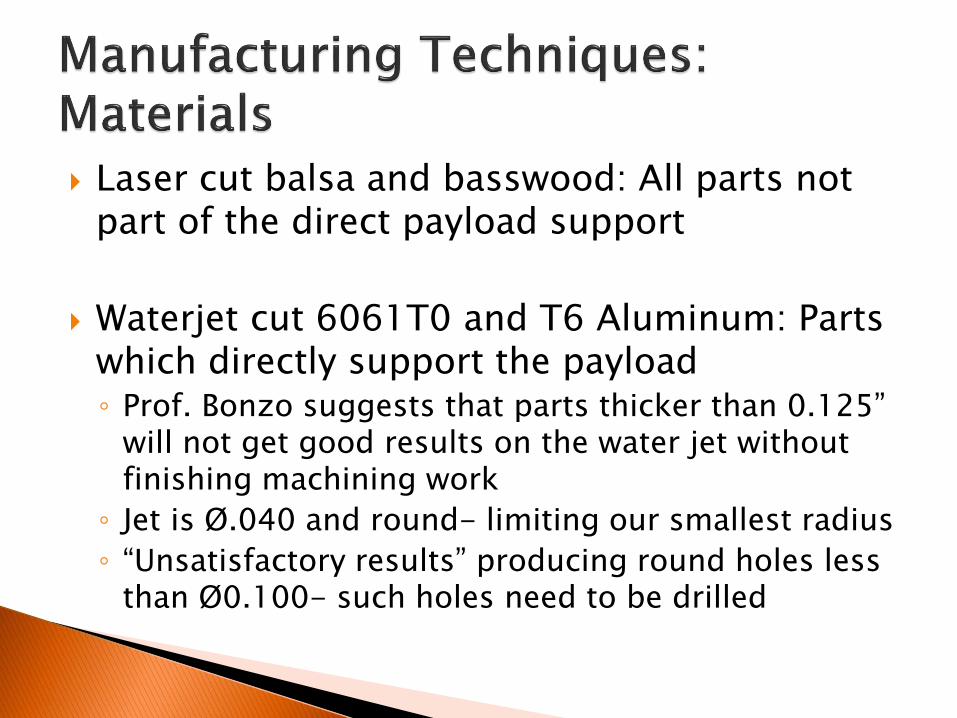
Laser cut balsa and basswood: All parts not part of the direct payload support
Waterjet cut 6061T0 and T6 Aluminum: Parts which directly support the payload◦ Prof. Bonzo suggests that parts thicker than 0.125”
will not get good results on the water jet without finishing machining work
◦ Jet is Ø.040 and round- limiting our smallest radius
◦ “Unsatisfactory results” producing round holes less than Ø0.100- such holes need to be drilled
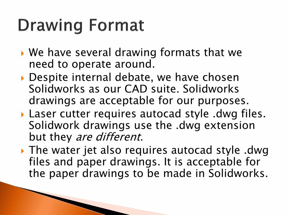
We have several drawing formats that we need to operate around.
Despite internal debate, we have chosen Solidworks as our CAD suite. Solidworksdrawings are acceptable for our purposes.
Laser cutter requires autocad style .dwg files. Solidwork drawings use the .dwg extension but they are different.
The water jet also requires autocad style .dwgfiles and paper drawings. It is acceptable for the paper drawings to be made in Solidworks.

The model broken down into its smaller components and analyzed
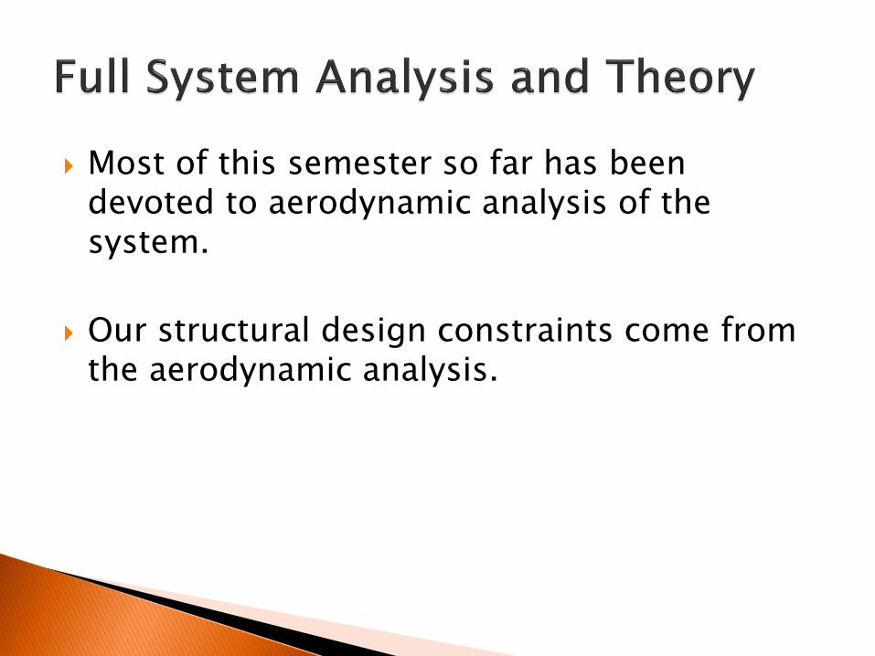
Most of this semester so far has been devoted to aerodynamic analysis of the system.
Our structural design constraints come from the aerodynamic analysis.

Aerodynamic Design and Sizing: Final Iteration
“Frozen” as of October 5th, 2015
Optimized for lift generation
Maintain static stability in accordance with cargo-transport aircraft criteria
Overall dimensions drive structural design

Final Sizing Diagram
This is the master sizing document. Requirements of this document and several auxiliary documents drove the structural design efforts.
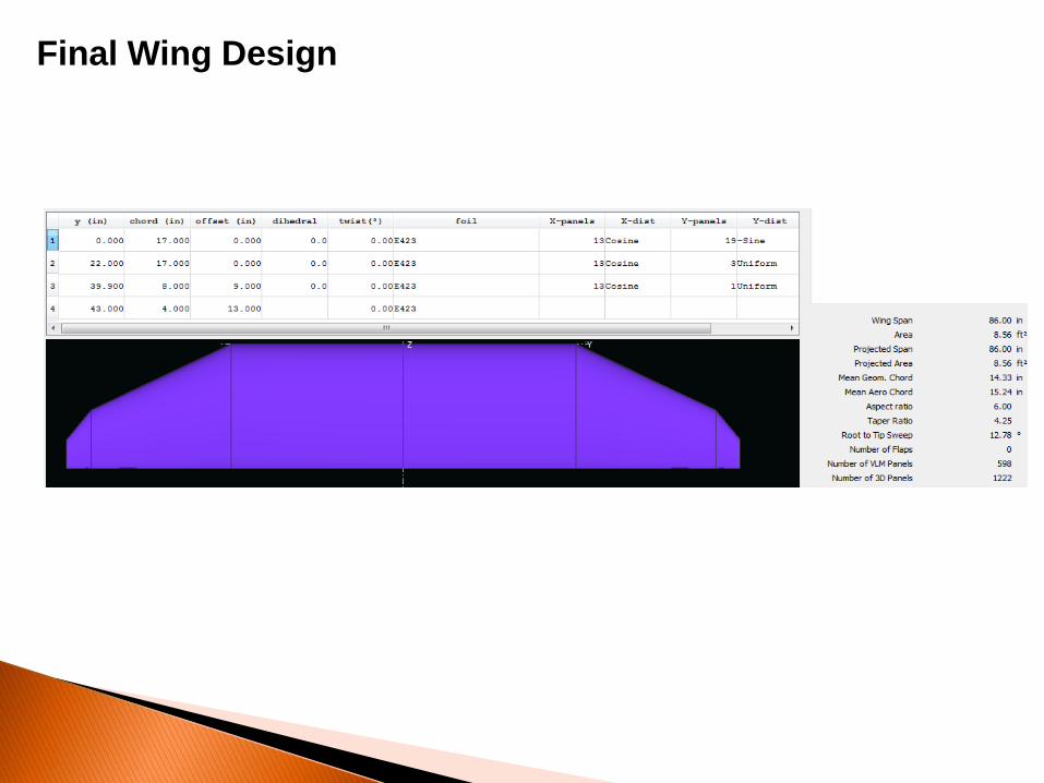
Final Wing Design
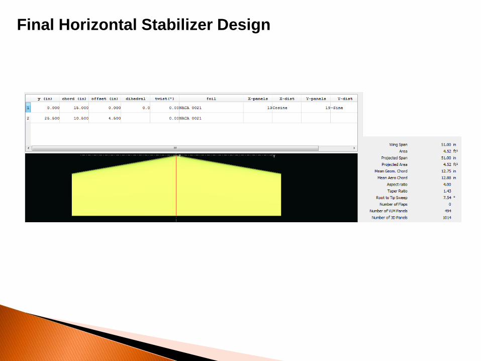
Final Horizontal Stabilizer Design
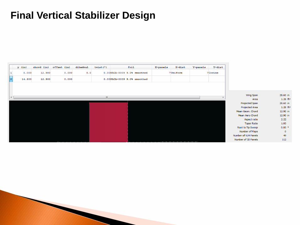
Final Vertical Stabilizer Design
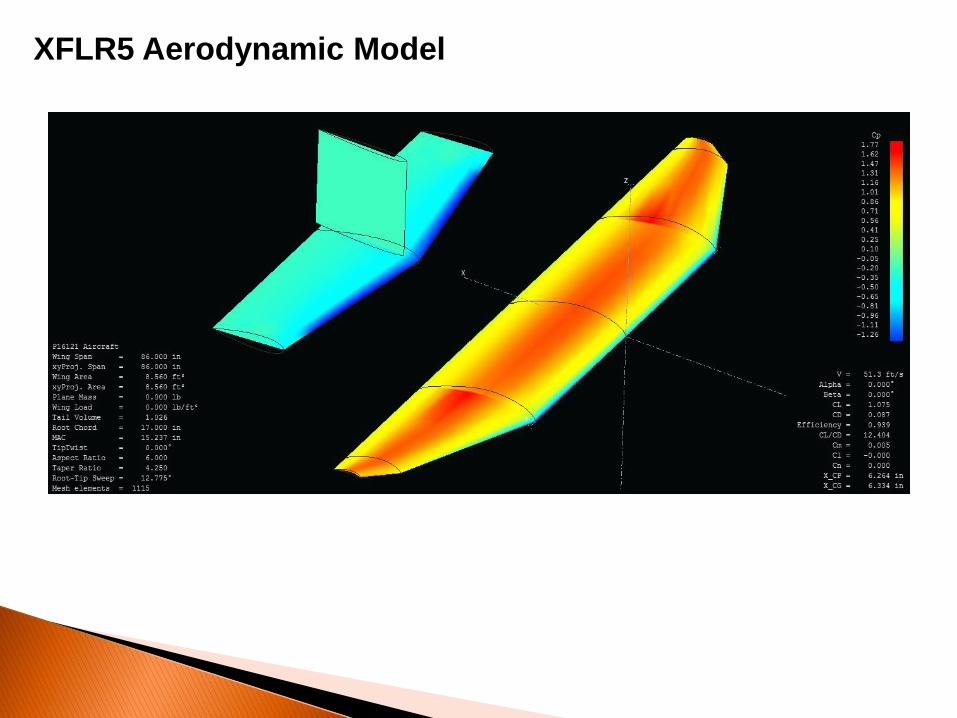
XFLR5 Aerodynamic Model

Fuselage Sizing
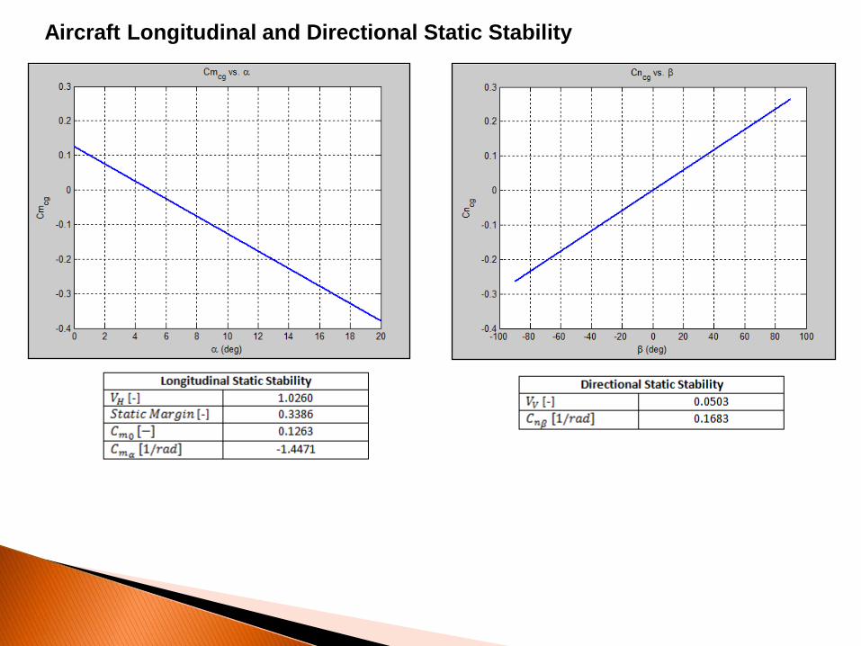
Aircraft Longitudinal and Directional Static Stability
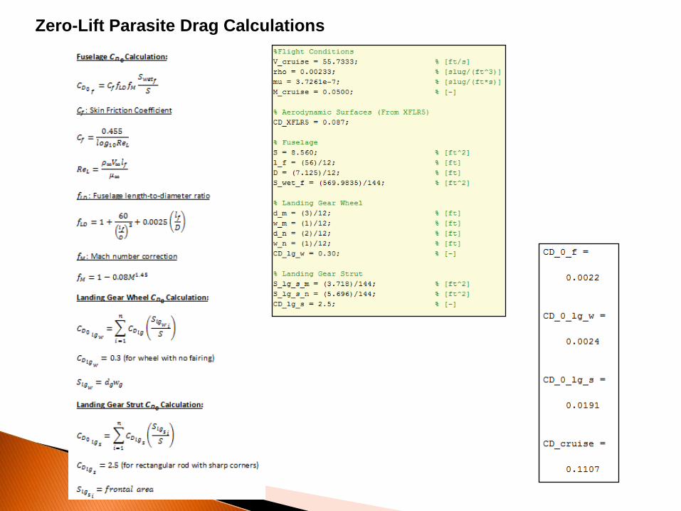
Zero-Lift Parasite Drag Calculations

Overall Aircraft Aerodynamics (From XFLR5 Convergence)
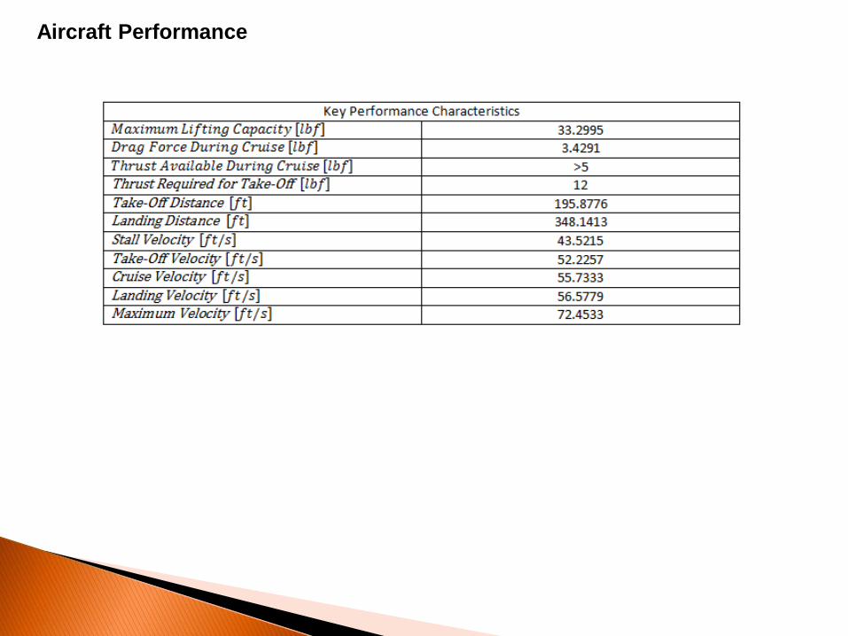
Aircraft Performance
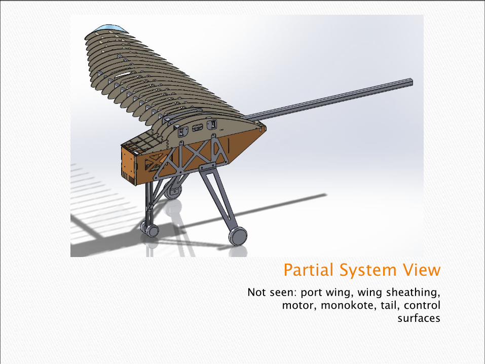
Partial System ViewNot seen: port wing, wing sheathing,
motor, monokote, tail, control surfaces
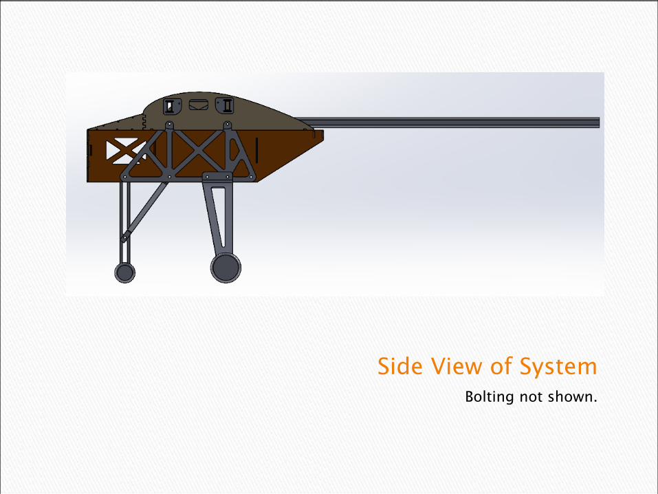
Side View of SystemBolting not shown.
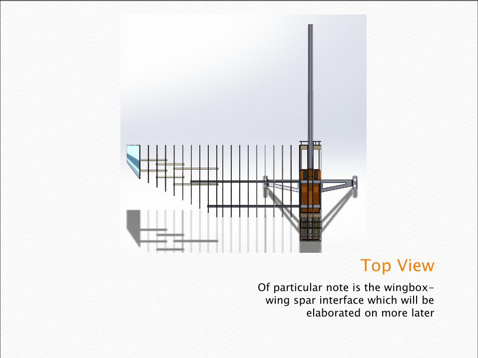
Top ViewOf particular note is the wingbox-
wing spar interface which will be elaborated on more later


The complete wingIn order to prevent the monokote from shrinking too much and distorting the shape we intend to sheath it in balsa.
Sheathing not shown for clarity.
Control surfaces are not included in this iteration of the design as their sizing is sensitive to these designs

Top View of Wing TipPresent in image is the transition
between all three wing profiles as well and other areas of interest
Main
Spars Foam
Wing
Tip

Side View of WingDemonstrating tendency of wing ribs
to migrate down and backward as a result of decreasing rib size
Main Spars
Outer Spars
Lightening/Wiring Holes


The WingboxInterfaces wings, tail and fuselage.
Accommodates the wiring that will run from the electronics bay to the control
surfaces.

Side View of Wingbox1”x0.5” rectangular aluminum spars connect each wing to the wing box.
Each will be pinned in place through the bottom of the box.
Spar interfaces
Bolt holes to interface
with fuselage
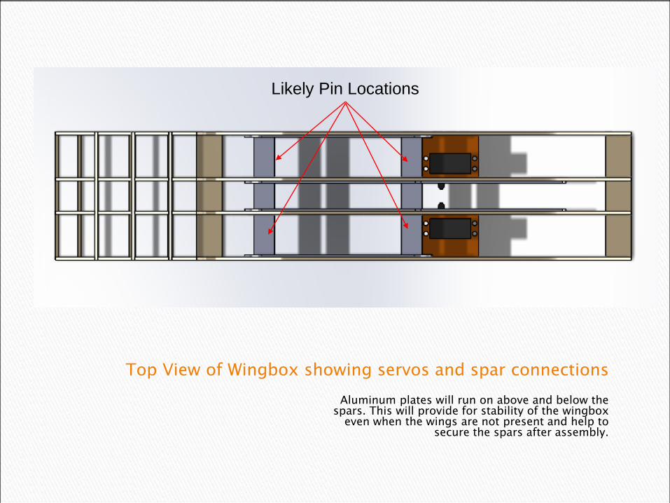
Top View of Wingbox showing servos and spar connections
Aluminum plates will run on above and below the spars. This will provide for stability of the wingbox
even when the wings are not present and help to secure the spars after assembly.
Likely Pin Locations
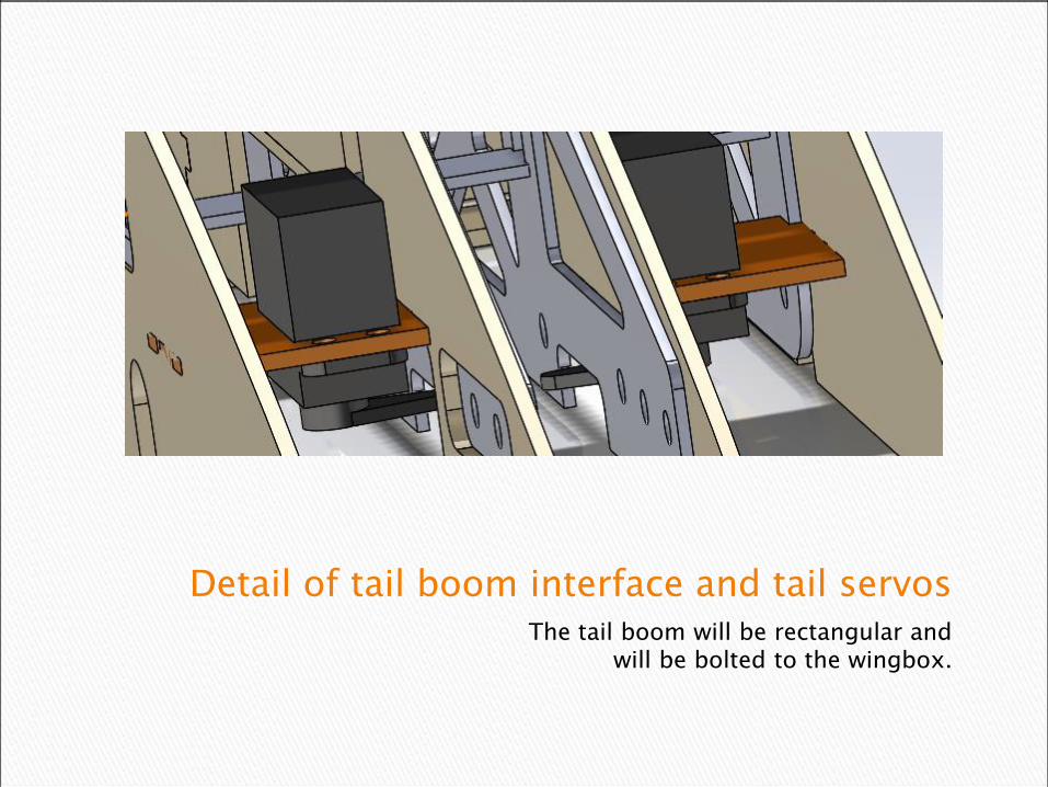
Detail of tail boom interface and tail servosThe tail boom will be rectangular and
will be bolted to the wingbox.
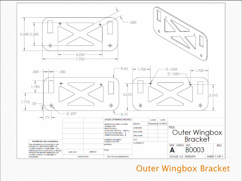
Outer Wingbox Bracket
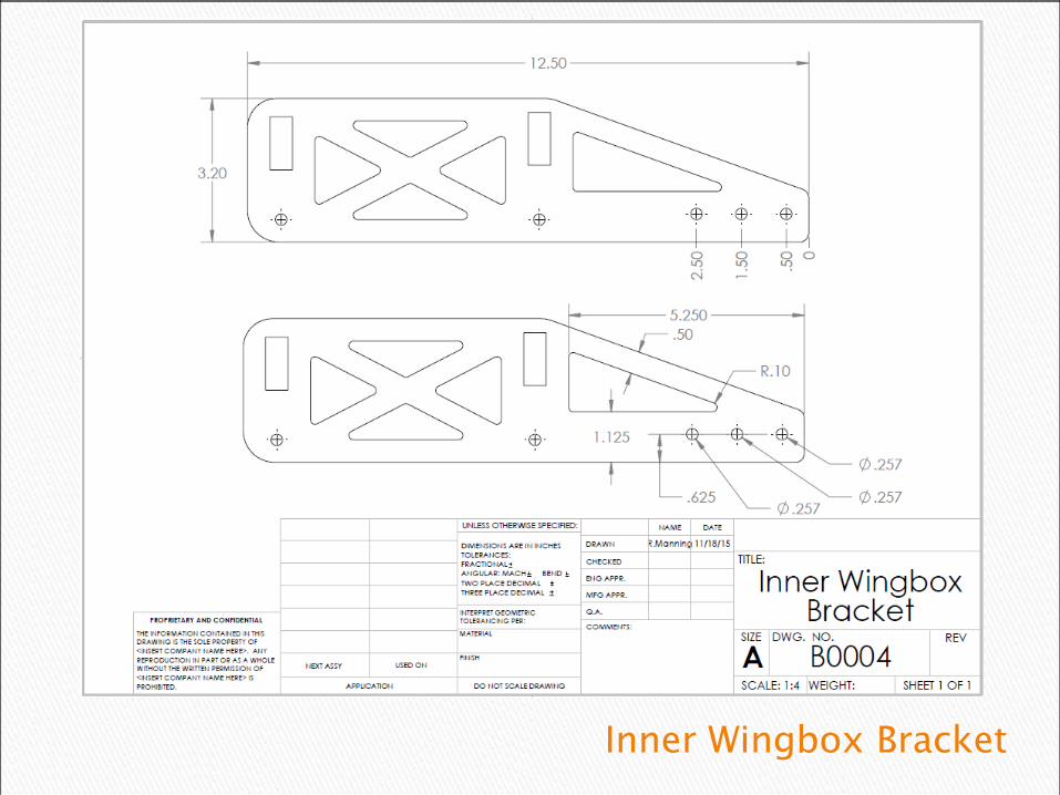
Inner Wingbox Bracket

Cross Strips

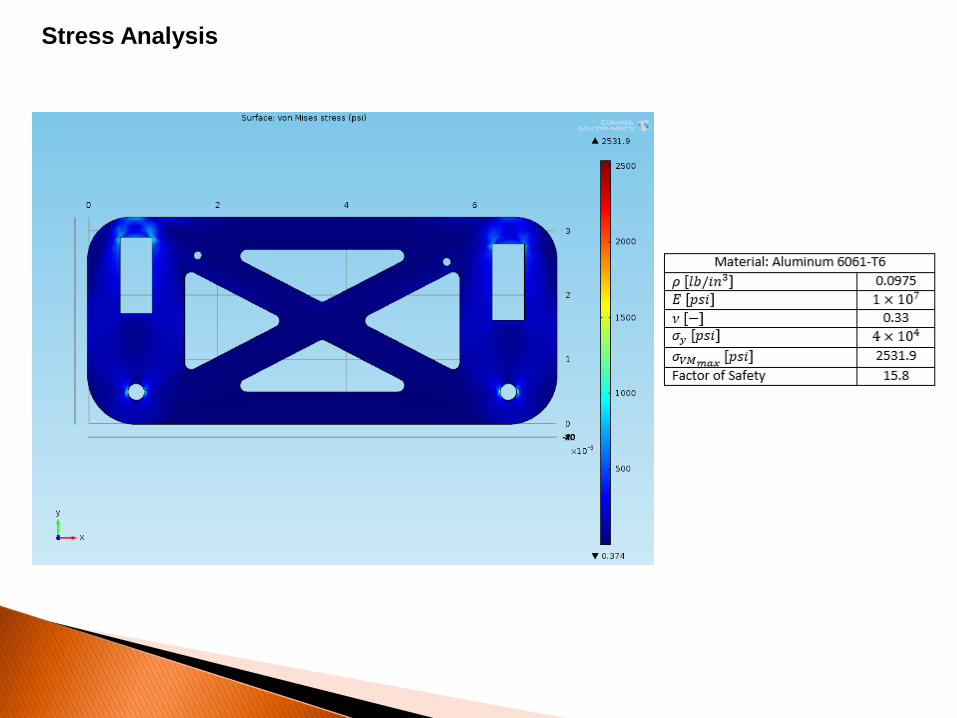
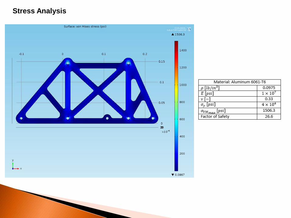
Stress Analysis

Stress Analysis


Detail View of the FuselageThe electronics bay is located forward of the
payload bay. Fuselage area aft of payload bay is simply present to support the arming plug and for
aerodynamic reasons.
Electronics Bay
Payload Bay
Motor Mount
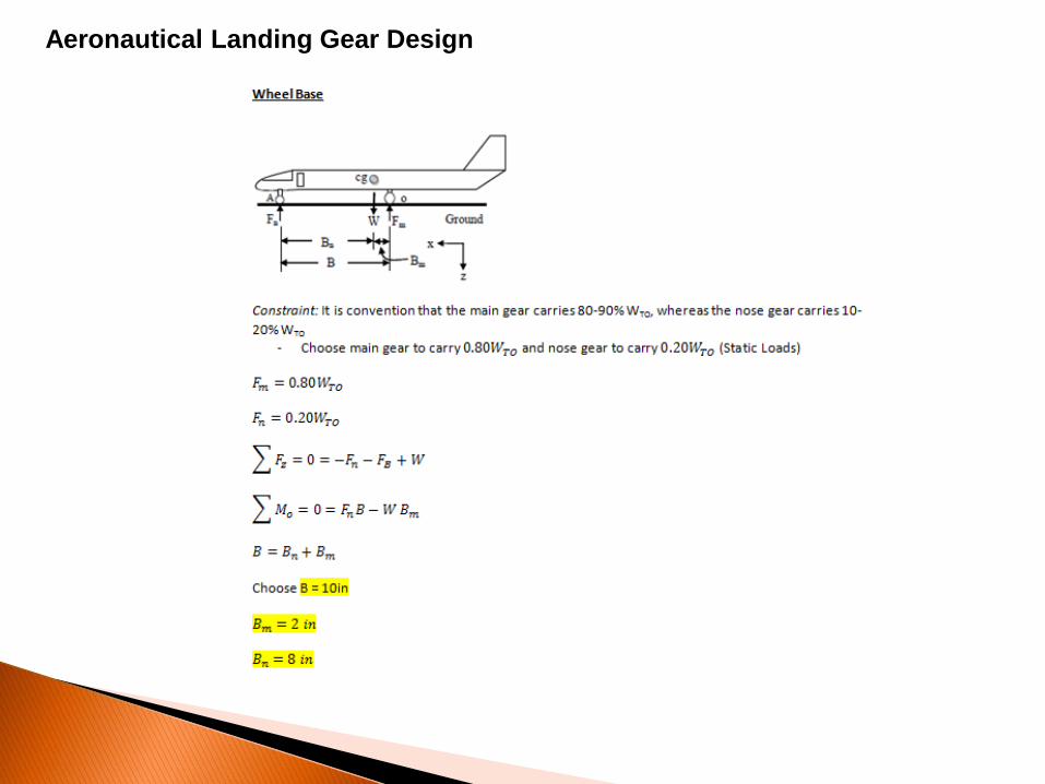
Aeronautical Landing Gear Design
Aeronautical Landing Gear Design Cont.

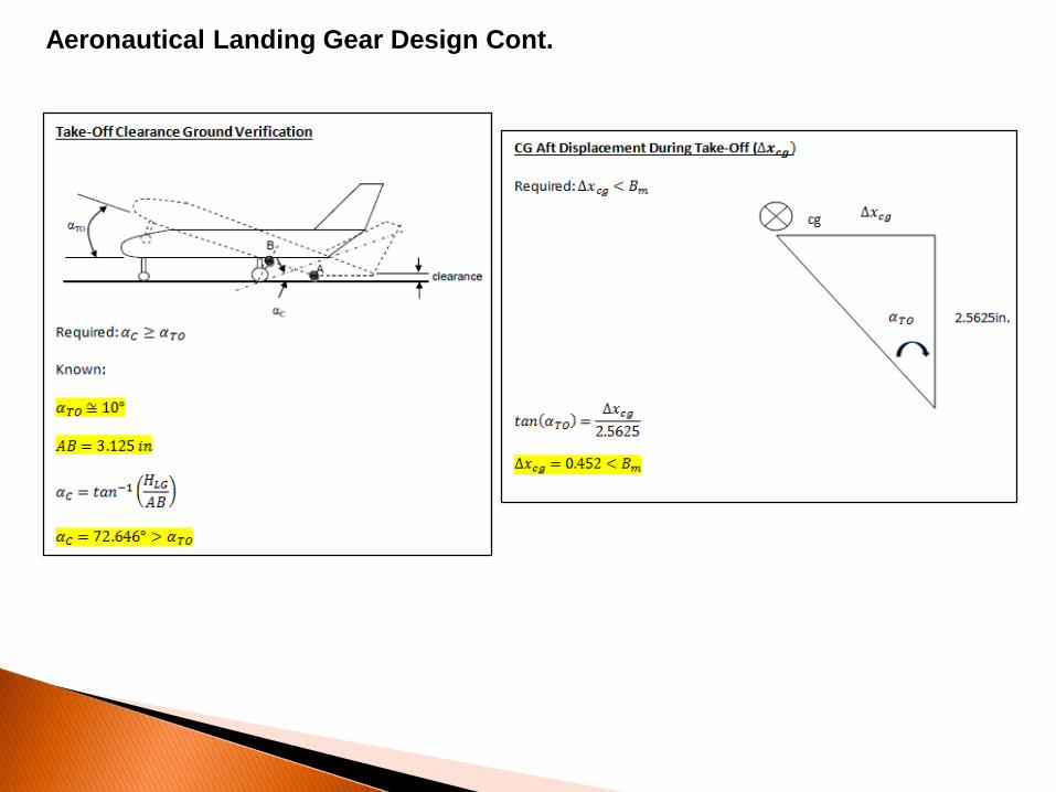
Aeronautical Landing Gear Design Cont.
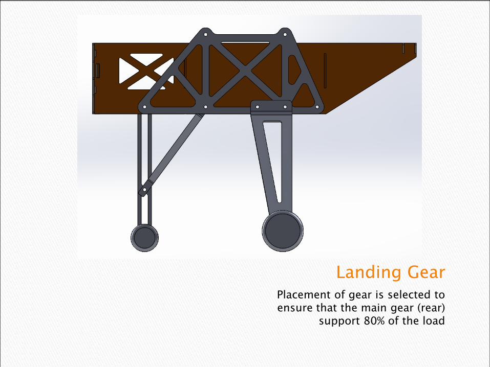
Landing GearPlacement of gear is selected to ensure that the main gear (rear)
support 80% of the load
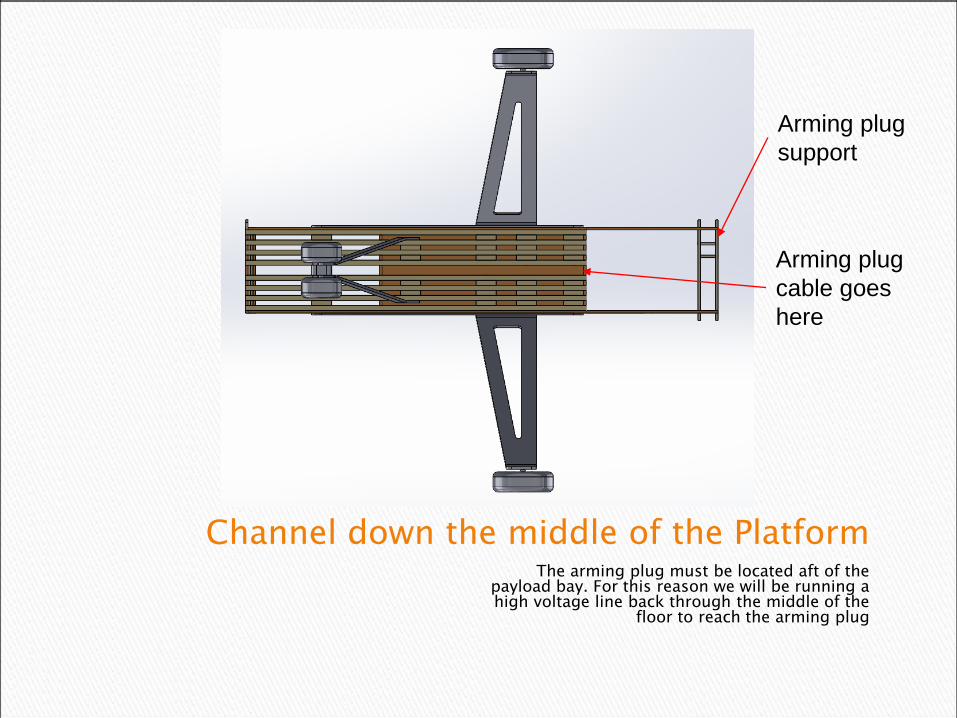
Channel down the middle of the PlatformThe arming plug must be located aft of the
payload bay. For this reason we will be running a high voltage line back through the middle of the
floor to reach the arming plug
Arming plug
cable goes
here
Arming plug
support

Rear ViewTrack is wide enough to ensure
ground stability

Stress Analysis

Stress Analysis
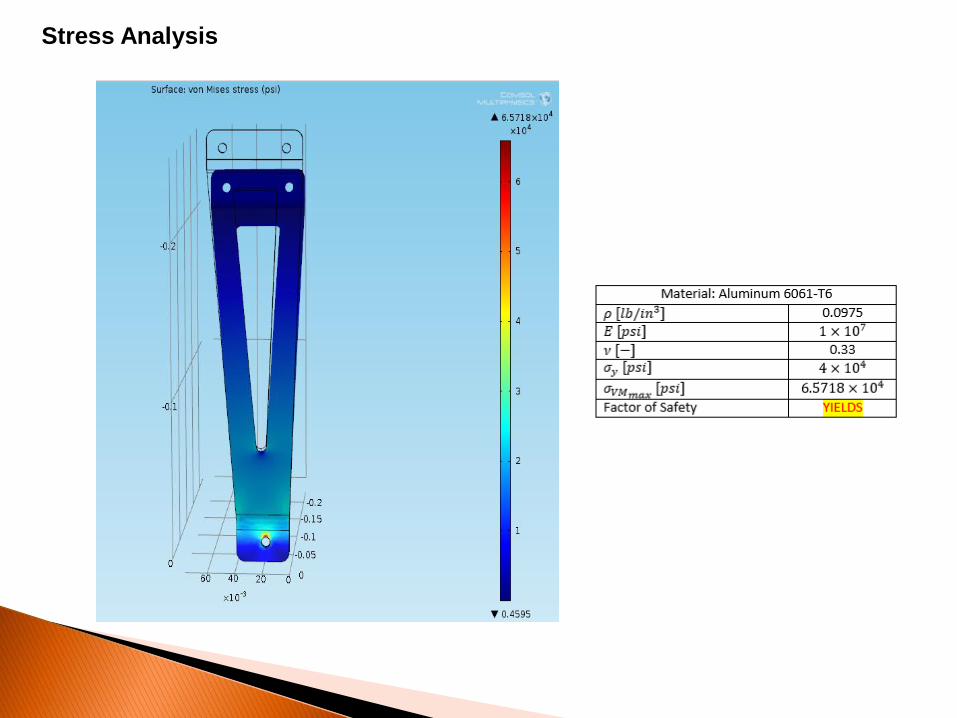
Stress Analysis
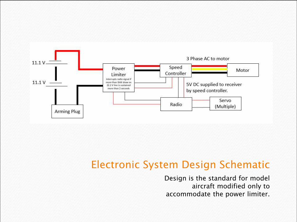
Electronic System Design SchematicDesign is the standard for model
aircraft modified only to accommodate the power limiter.

What we have, what we need, and how we plan to get it
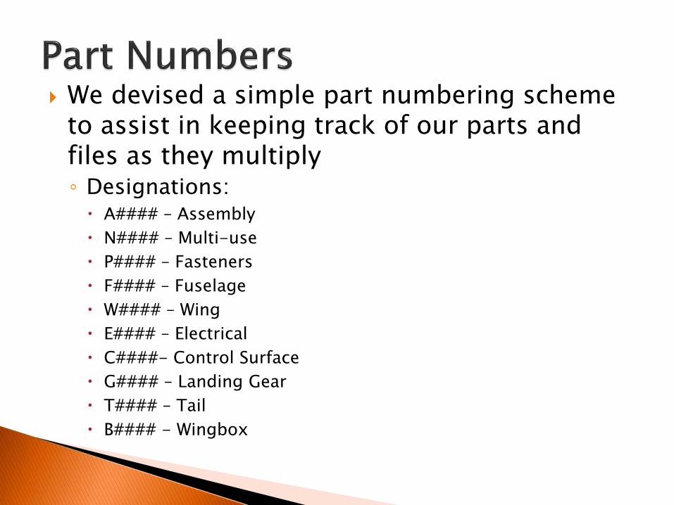
We devised a simple part numbering scheme to assist in keeping track of our parts and files as they multiply◦ Designations:
A#### – Assembly
N#### – Multi-use
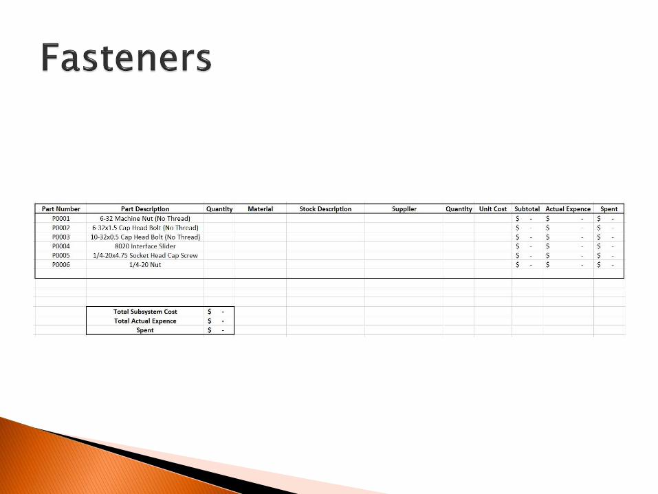
P#### – Fasteners
F#### – Fuselage
W#### – Wing
E#### – Electrical
C####- Control Surface
G#### – Landing Gear
T#### – Tail
B#### - Wingbox

• Budget is as of current bill of materials
• Not Included: Tail, Landing Gear, Fasteners
• Cost will increase as design progresses


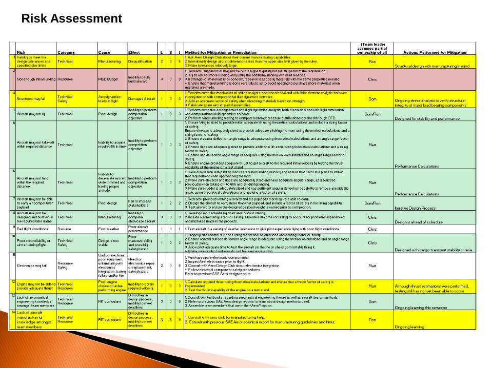
Risk Assessment
