preliminary design review: pneumatic system
TRANSCRIPT

1
Preliminary Design Review:
Pneumatic System
Moises Barba and Francisco Merida
Engineering Design and Development
December 8th 2013
2
Element F:
Consideration of Design Viability

3
I. MARKET ANALYSIS Potential Competitors
Team 1717 - Dos Pueblos Engineering
Academy
Team 1114 - Simbotics
Team 254 - The Cheesy Poofs
Why are they better competitors?
Team 1717 focuses on important aspects
of the game and divides their team into
divisions that work separately but come
together to build one robot. These
divisions consist of the build team, chassis
team and depending on the game a
collector team. For example in 2013
competition this team built a pneumatic
collection mechanism that would pick
Frisbees up from the ground and throw
them out in less than 10 seconds and this
was an idea brought out by the collector
team, who was focused specifically on
how pneumatics was applicable to their
robot. This is significant because their
pneumatic collector gave them the
privilege of not having to go to their
feeder station every time to get Frisbees.
Instead, they were able to pick up
Frisbees off of the playing field, making
them much quicker between shot pickup
and the actual shot. If compared to Team
4201’s Leo Robot, one can see that the
lack of a feeder system that gathers
Frisbees from the playing field is what cut
off time for their robot to shoot. Their
robot was more often at the feeder station
than the field due to problems feeding
through the feeding chamber. This shows
us that pneumatics is important because
it allows us to solve problems that save us
time on the field, and that give us more
time to be making points.
Team 1114, known as the Simbotics team,
is a potential competitor because they
have more experience and have been with
FIRST long enough to experiment
different uses of pneumatic system. For
example, in the 2005 Triple Play FRC
Competition they were able to create a
pneumatic arm grabber to stack and
organize bins. This system was very
effective because the pneumatic piston
was able to exert force in one direction,
and maintain that position despite how
heavy the bins may have been. This is
because a pneumatics system allows the
user to apply force using air pressure.
Because they were able to use air
pressure to exert a constant, solid force,
they were able to organize a large amount
of bins without any of them falling as they
were taken to their base. Ultimately, this
is what gave them the upper hand in the
competition, and what allowed them to
win 2nd place in the regional competition
for that year. This further shows that they
are experts in this field, and this fact is
confirmed through their own website,
where they explain how pneumatics
works and give a full on manual as to how
other teams can implement pneumatics
into their own bots.

4
In addition, in 2004 they were recognized
for winning 8 FRC. 2004 was 9 years ago,
giving room for this team to experiment
various times and get to know what
works best and what does not work. Plus,
they have had time to develop fundraising
that provides them with tools to generate
better products for their Robot for
example a stronger Drive Train or better
chassis.
Team 254 has been in FRC for quite a
while and has also experimented on
different uses of pneumatic systems. In
2010 they used a pneumatic system to
shoot t-shirts at potential fans. This
shooting system is significant because it
shows the depth of knowledge this team
has with pneumatics. Their
understanding of pneumatics is so
profound, that they have the time to
create a system that isn’t even meant for
competition. This shirt launcher is a
testament to the fact that a team’s
understanding of pneumatics is crucial in
the robot design process. Team 254 had a
solid understanding of it, as evidenced
through the shirt launcher, meaning that
understanding pneumatics must have
been worthwhile for their team.
The application of pneumatics into a shirt
launcher is also significant to a team’s
success because it can be used to solve
the problem of marketing the team. Team
254 did this through their shirt cannon,
the Shockwave, which, through the use of
pressurized air, was able to shoot t-shirts
at a rate of 3 shirts per second. These
shirts promoted their team and their
sponsors, giving them more
representation when it came time for
fundraising. Through this, one can see
how flexible the applications of
pneumatics are, and that they can
contribute to Team 4201’s success in and
out of the field.
Cost
Things needed for this build:
• Compressor = $69
http://www.andymark.com/SearchResult
s.asp?Search=compressor
• Tank 500ml=$15
http://www.andymark.com/SearchResult
s.asp?Search=tank
• Cylinder =$30
http://www.andymark.com/product-
p/am-0591.htm
• Hose=$18
http://www.andymark.com/product-
p/am-2137.htm
• 10 fittings =$2.50 Each
http://www.andymark.com/SearchResult
s.asp?Search=1%2F4+fittings
• regulator=$28
http://www.andymark.com/SearchResult
s.asp?Search=regulator
• two solenoids=$83 each
http://www.andymark.com/product-
p/am-2343.htm
• Solenoid breakout=$24
http://www.andymark.com/product-
p/am-0868.htm
5
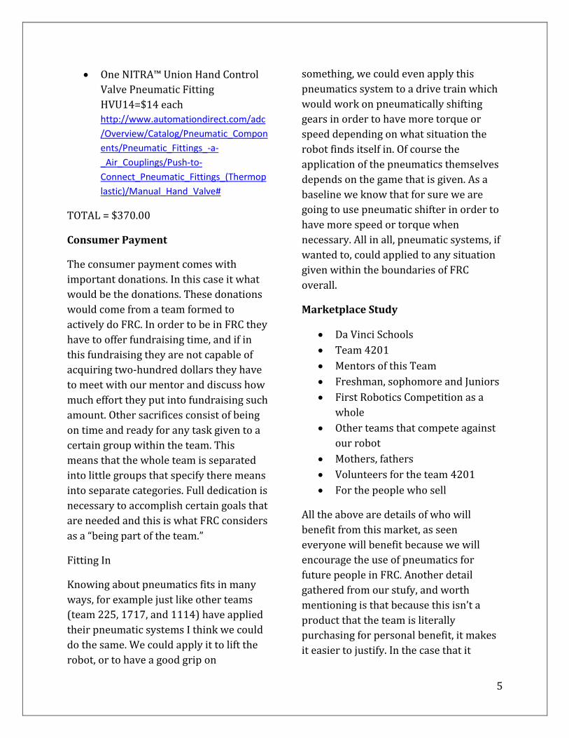
One NITRA™ Union Hand Control
Valve Pneumatic Fitting
HVU14=$14 each
http://www.automationdirect.com/adc
/Overview/Catalog/Pneumatic_Compon
ents/Pneumatic_Fittings_-a-
_Air_Couplings/Push-to-
Connect_Pneumatic_Fittings_(Thermop
lastic)/Manual_Hand_Valve#
TOTAL = $370.00
Consumer Payment
The consumer payment comes with
important donations. In this case it what
would be the donations. These donations
would come from a team formed to
actively do FRC. In order to be in FRC they
have to offer fundraising time, and if in
this fundraising they are not capable of
acquiring two-hundred dollars they have
to meet with our mentor and discuss how
much effort they put into fundraising such
amount. Other sacrifices consist of being
on time and ready for any task given to a
certain group within the team. This
means that the whole team is separated
into little groups that specify there means
into separate categories. Full dedication is
necessary to accomplish certain goals that
are needed and this is what FRC considers
as a “being part of the team.”
Fitting In
Knowing about pneumatics fits in many
ways, for example just like other teams
(team 225, 1717, and 1114) have applied
their pneumatic systems I think we could
do the same. We could apply it to lift the
robot, or to have a good grip on
something, we could even apply this
pneumatics system to a drive train which
would work on pneumatically shifting
gears in order to have more torque or
speed depending on what situation the
robot finds itself in. Of course the
application of the pneumatics themselves
depends on the game that is given. As a
baseline we know that for sure we are
going to use pneumatic shifter in order to
have more speed or torque when
necessary. All in all, pneumatic systems, if
wanted to, could applied to any situation
given within the boundaries of FRC
overall.
Marketplace Study
Da Vinci Schools
Team 4201
Mentors of this Team
Freshman, sophomore and Juniors
First Robotics Competition as a
whole
Other teams that compete against
our robot
Mothers, fathers
Volunteers for the team 4201
For the people who sell
All the above are details of who will
benefit from this market, as seen
everyone will benefit because we will
encourage the use of pneumatics for
future people in FRC. Another detail
gathered from our stufy, and worth
mentioning is that because this isn’t a
product that the team is literally
purchasing for personal benefit, it makes
it easier to justify. In the case that it

6
would be meant for one specific person,
justifying this problem would be much
more difficult because the consumer
wouldn’t have Team 4201 in mind. In this
case, because most of the people
benefiting from this product are on the
team, we are able to justify this problem
by showing how it will benefit the team
overall, rather than one specific person.
Demand
In team 4201 there is no one who really
knows how pneumatic systems actually
work and this could be seen in the past
years that the robot has been developed.
Not one in FRC within the last two years
has applied any mechanism or a
pneumatic system to the robot to make it
do a certain task. We know that the
demand for some type of pneumatic
system will present itself whether that is
shifting gears, making the robot jump or
simply using it to actually grip something
with a claw of some sort. As explained
earlier one of the things that should be a
baseline and a definite is applying
pneumatics to a gear shifter. Ultimately,
there is a demand in the fact that
pneumatics will allow our team’s
successes to increase. As briefly analyzed,
previous years haven’t shown us much
success due to the fact that we haven’t
been as effective with all of the resources
we are presented with. Pneumatics has
been one of those resources, and out of all
of the ones we haven’t used, is quite
frankly the most effective due to its
adaptability to many different problems
and efficiency.
Who and Why
This product will be used by Team 4201
and anyone that is directly/indirectly
associated. Use can be defined anywhere
from receiving satisfaction that our team
has won, to literally controlling the
system during competition.
This product is worth buying because it
will expand the Team 4201’s
resourcefulness, giving them more tools
to solve more problems. As demonstrated
by our competitors, pneumatics can be
used to solve an array of problems:
shifting gears, shooting shirts, grabbing
bins, making claws, making feeders, lifting
robots, etc. More importantly, this range
of solutions assesses two larger
problems: success on the field, and
marketing for the team.
Success on the field will be almost fully
guaranteed by using pneumatic systems
because pneumatic systems will allow
Team 4201 to solve problems in more
unique and efficient ways. A prime
example of how Team 4201 could have
done so in the 2013 build season is by
having used a pneumatic gear shifter,
instead of not shifting gears at all. Our
Engineering Tostado specifically stated
that Leo’s inability to shift is what made it
so slow, and thus, what gave it less time to
shoot Frisbees and score points. Firstly,
pneumatics would have given the team
the ability to shift from low gear and high
gear, meaning that the problem
mentioned by Tostado could be solved. So
too, the implementation of pneumatics
would have expanded the Teams

7
knowledge of how to apply pneumatics to
assess other problems that needed to be
solved, even that of using pneumatics for
the 2014 season.
Our competitors have already proven that
pneumatics is worthy of using, as some
teams even thought it was so useful that
they used pneumatics to make a t-shirt
cannon. It is almost not even a question to
ask if pneumatics should be included in
the 2014 season or not. The answer has
been yes ever since our team started,
simply because it can solve more
problems, more effectively than any other
tool/resource at our disposal.
Our product will not be bought but
instead it would be useful like a tool and
why should they bother to try it? This is
because can be, and will be applied to any
circumstance because in many ways it
gives power where a motor or a sim
motor cannot. If it is that we create a type
of pneumatic system that works
standardly in a drive train and it is useful
to other teams in this other teams will
gain product use and they will try it. As
shown to us by our competitors, the range
of problems that pneumatics can solve,
and the effectiveness by which it can do
so shows that our consumers (the team)
will be inclined to use pneumatics as
another tool to solve whichever problem
presented in the 2014 season.
Manufacturing
Our products are manufactured by Viair,
CKD, Bimba, Nason, and Norgren. These
companies provide us with air
compressors, tanks, fittings, solenoids,
joints, gauges, regulators, and pneumatic
hose. These products are purchased
through AndyMark. Using these
companies for the manufacturing of our
product is more than reasonable because
these companies are experts in their
fields. For example, CKD is internationally
recognized as a solenoid provider for
companies and organizations like FRC.
They have the manufacturing tools
necessary to produce solenoids on a large
scale, meaning that their products have
been proven to be effective by consumers.
Our role in the manufacturing process is
to simply put these parts together, which
means that we won’t have to depend on
any lower scale machinery to make our
design come to life.
Our product will be manufactured in Da
Vinci Science where we will be able to test
and see results afterwards. Because the
purpose of knowing pneumatics is to
apply it to FRC challenges, then it will
most definitely be applied in the 2014
build season. The knowledge taken from
our research and our studies would be for
the purpose to orient people and give
them something that no one knows how
to use. Members themselves will be
working through the manufacturing
process by putting the pneumatics
components together, testing the
components, and possibly, using the robot
on the field. This is more than reasonable
because we give our peers the sense of
confidence they will need in order to
apply pneumatics to any competition they
are in.

8
Element: D
Design Concept Generation, Analysis, and
Selection
9
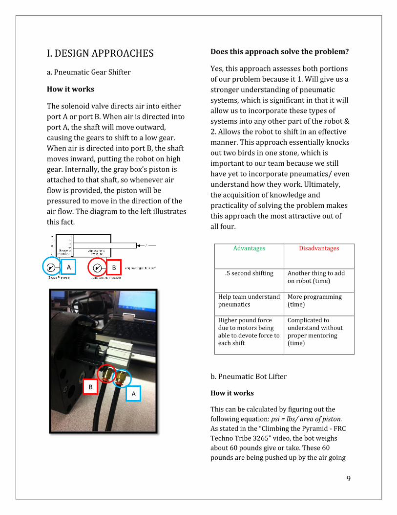
I. DESIGN APPROACHES
a. Pneumatic Gear Shifter
How it works
The solenoid valve directs air into either
port A or port B. When air is directed into
port A, the shaft will move outward,
causing the gears to shift to a low gear.
When air is directed into port B, the shaft
moves inward, putting the robot on high
gear. Internally, the gray box’s piston is
attached to that shaft, so whenever air
flow is provided, the piston will be
pressured to move in the direction of the
air flow. The diagram to the left illustrates
this fact.
Does this approach solve the problem?
Yes, this approach assesses both portions
of our problem because it 1. Will give us a
stronger understanding of pneumatic
systems, which is significant in that it will
allow us to incorporate these types of
systems into any other part of the robot &
2. Allows the robot to shift in an effective
manner. This approach essentially knocks
out two birds in one stone, which is
important to our team because we still
have yet to incorporate pneumatics/ even
understand how they work. Ultimately,
the acquisition of knowledge and
practicality of solving the problem makes
this approach the most attractive out of
all four.
b. Pneumatic Bot Lifter
How it works
This can be calculated by figuring out the
following equation: psi = lbs/ area of piston.
As stated in the “Climbing the Pyramid - FRC
Techno Tribe 3265” video, the bot weighs
about 60 pounds give or take. These 60
pounds are being pushed up by the air going
Advantages Disadvantages
.5 second shifting Another thing to add on robot (time)
Help team understand pneumatics
More programming (time)
Higher pound force due to motors being able to devote force to each shift
Complicated to understand without proper mentoring (time)
B A
A B

10
against the piston, meaning that the piston’s
head is what is withholding the downward
force that the bot is counteracting with. To
find pounds force, we divide 60 lbs by 2(3
inches squared) otherwise known as (the
surface area of the combined piston heads).
This gives us 10 lbs force, meaning that for
every inch of the pneumatic piston, the
system must provide 10 PSI. Because there’s
a total of 6 inches of area, the system must be
adjusted to 60 psi to lift, even greater as to
get the robot to a higher position.
Does this approach solve the problem?
Yes, but this approach only assesses one
portion of our problem, that our team’s lack
of knowledge of pneumatic systems has
bottlenecked our team’s potential. This is
because this system involves the lifting
mechanism, whereas we’re focusing on
shifting the drive train. This approach can
also be taken on, however, in addition to
approach number one, so that we get an even
stronger understanding of pneumatic systems
through different applications.
Advantages Disadvantages
Reliable lift Potential to fail if lbs force exceeds psi
Cleaner system
Air pressure may lower due to prolonged stress
Stronger understanding of
pneumatics
Complicated to understand without proper mentoring (time)
c. Pneumatic Shot Adjuster
How it Works
There are other possible explanations as
to how a pneumatic shooter can be
adjusted. The easiest way to actually
grasp the idea of a pneumatic shooter is
by attaching a cylinder to a base plate
where the shooter is located. By using this
cylinder we can make the piston attach
directly to the base plate. This cylinder
definitely has to be big enough to be able
to adjust the shooter in numerous
elevations. By using a cylinder you can
also have the capability to make the
shooter get low enough for the robot to
seem compatible. By programming the
pneumatics to elevate or lower to a
certain distance it can almost be

11
guaranteed success when shooting at a
particular goal.
Does this approach solve the problem?
Well this approach makes moving the
shooter in different angles a lot smoother
and easier. The only disadvantage is the
time it will take only to perform this task
plus it is really doubtful that this robot
will be able to climb. But that will depend
on the designing of the pneumatic system
all over the robot itself. There is not a yes
or no answer this question must depend
on the situation we are in and how much
weight we are playing with overall in the
robot. There is the possibility that with
this type of shooter we are capable of
performing a faster shot in less time but
that would depend on how fast the
shooter is lifted.
12
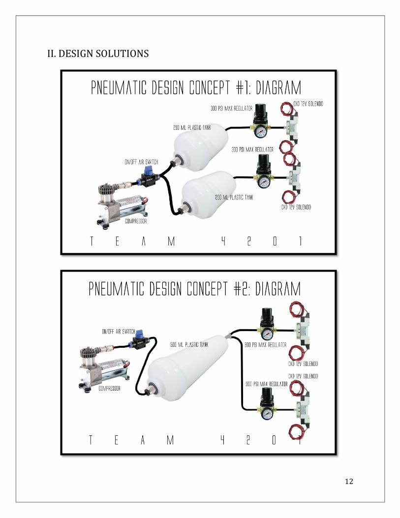
II. DESIGN SOLUTIONS
13
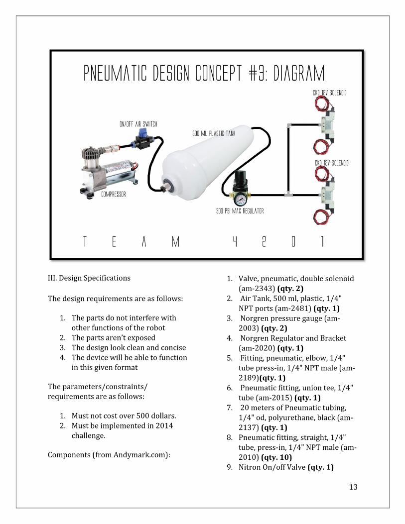
III. Design Specifications
The design requirements are as follows:
1. The parts do not interfere with other functions of the robot
2. The parts aren’t exposed 3. The design look clean and concise 4. The device will be able to function
in this given format
The parameters/constraints/ requirements are as follows:
1. Must not cost over 500 dollars. 2. Must be implemented in 2014
challenge.
Components (from Andymark.com):
1. Valve, pneumatic, double solenoid
(am-2343) (qty. 2) 2. Air Tank, 500 ml, plastic, 1/4"
NPT ports (am-2481) (qty. 1) 3. Norgren pressure gauge (am-
2003) (qty. 2) 4. Norgren Regulator and Bracket
(am-2020) (qty. 1) 5. Fitting, pneumatic, elbow, 1/4"
tube press-in, 1/4" NPT male (am-2189)(qty. 1)
6. Pneumatic fitting, union tee, 1/4"
tube (am-2015) (qty. 1) 7. 20 meters of Pneumatic tubing,
1/4" od, polyurethane, black (am-2137) (qty. 1)
8. Pneumatic fitting, straight, 1/4" tube, press-in, 1/4" NPT male (am-2010) (qty. 10)
9. Nitron On/off Valve (qty. 1)
14
With these three constraints in mind,
Francisco and I created a symmetrical
design that would be able to direct air to
gearboxes on both sides of the robot. The
primary component that keeps the entire
system running is the compressor. This
compressor is placed in that rear middle
end of the robot chassis, where it can
adequately direct compressed air to both
sides of the bot. The pneumatic elbow
fitting will then be connected to a t joint.
This t joint will have pneumatic tubing
directed to the left and right long sides of
the robot. About 1/10’ths down these
sides, we will have the air tank. A short
distance from the air tank, we’ll have a
regulator to ensure that we do not blow
our solenoid. Immediately after, we’ll
have the solenoid valve, which will then
connect to the gear shifter itself.
These parameters were determined with
simple logic.
1. The parts do not interfere with other
functions of the robot
This was determined on the basis that we
need the robot to be fully functional. It is
only logical that the pneumatic system
won’t interfere with other portions of the
design.
2. The device will be able to function in
this given format
We need to make sure that the system
works in the format it is in. Furthermore,
we made this a constraint to ensure that
this would happen. Without functionality,
we won’t be able to shift, and will be in
the same position we were last year.
3. The parts aren’t exposed
Ensuring that parts aren’t exposed is very
significant because during competition,
there is a very high chance that we’ll be
bumping into other bots. Therefore, we
must ensure that the parts aren’t exposed
so that the pneumatics system is not
damaged.
4. The design looks clean and concise
Considering that we’re making the chassis
from scratch, and we’re using nice metals,
we thought it would be significant to
make this look clean. It will add to the
overall feel of the robot, and will have a
greater intimidation factor on the field.
Reflection
The device will in fact, and has done so
already, worked in this given format. On
November 27th of 2013, we met with Fuz,
our project mentor, who specifically
helped us set up this system. We had his
professional approval of its ability to
function, meaning that we have met goal
#2. After conceptually thinking about how
this system will be implemented, we
realized that it would look clean, and not
be exposed. This is why we’ve decided to
use a t style joint prior to the two
solenoids. Doing so keeps the system nice
and clean on the robot, and ensures that
nothing is exposed. This problem was also
solved by using only one tank, as doing so
minimized the space required for the
system to work.

15
IV. DECISION MATRIX
Ease of use Chassis Adaptability
Weight Price Total Ineffective Ok Great
Design #1 7 + 6 = 13 13/2 = 6.5
6 + 4 = 10 10/2 = 5
7 + 8 = 15 15/2 = 7.5
7 + 7 = 14 14/2 = 7
26
Design #2 8 + 9 = 17 17/2 = 8.5
8 + 7 = 17 15/2 = 7.5
7.5 + 8.5 = 16 16/2 = 8
8 + 8 = 16 16/2 = 8
32
Design #3 10 + 9 = 19 19/2 = 9.5
8 + 9 = 15 17/2 = 8.5
10 + 9 = 19 19/2 = 9.5
9 + 9.5 = 18.5 18.5/2 = 9.25
36.75
V. DESIGN JUSTIFICATION
For the past 2 years, Team 4201 has
lacked an understanding of pneumatics,
and even an effective system to shift the
gears of its robot’s chassis. No specific
group of people has taken the initiative to
assess these two problems. Although
other solutions may have distracted us
from using pneumatics, such as not
shifting gears at all, no other solution
directly assesses this problem with the
level of added benefits and effectiveness.
Against Other Solutions
The only other solution to gear shifting on
the market is Andy Mark’s Sonic Shifter.
Andy Mark’s Sonic Shifter, although it
assesses the problem at hand, which is
that the team needs to be able to shift to
gain speed, fails in that it does not provide
the same type of response and force as a
pneumatics system. This is evidenced by
Andy Mark’s catalog on the Sonic Shifter:
“This is a slow, weaker method of shifting (compared to
pneumatic), taking 1.5-2 seconds and pushing with up
to 8.5 pounds of force. A robot driver may need to back
off of the throttle to let a servo shift gears while
moving.”
When compared to the pneumatic shifter,
the two motor approach is WEAK:
“This is a strong, fast method of shifting, lasting under
0.5 seconds and pushing with 26 pounds of force (if
using 60 psi). This pneumatic shift can be done while a
robot is accelerating.”
From this evidence, it is clear that using
two motors would bottleneck the
potential of our robot by a complete
second and a half AND by 14 pounds of
force! Secondly, a pneumatics system
allows us to accelerate while shifting,
meaning that we won’t have to stop or
slow down to shift.
Lastly, this system would cause us, once
again, to ignore implementing pneumatics
into our robot. This is significant because
this means not only that we’re losing
speed, but that we’re losing the potential
to implement pneumatics in other parts
16
of our robot. The fact that our proposed
approach requires pneumatics, almost
forces us to learn and fully understand
pneumatics, which will help us greatly in
the future career of Leo by allowing us to
use pneumatics for whichever application
necessary.
Against Similar Designs
Design #3 is the better design out of the
two others because it is easier to use,
cheaper, lighter, and can better adapt to
the chassis.
It better meets these 4 categories due to
the fact that, after calculations, Design #3
costs $30 less than Design #2, and $45
less than Design #1. The best part is, that
is doesn’t lose performance by lacking
these funds; instead, it is better because it
lacks this amount of funds. This is
because the parts that contribute to the
price difference between designs are
unnecessary. For example, it is
unnecessary for Design #1 to have 2
tanks, just as it is unnecessary for Design
#2 to have two regulators. These
unnecessary parts aren’t only pointless,
they make the robot heavier, more
complex to use, and don’t adapt to the
chassis as easily. The two regulator
system is unnecessary because it requires
for us to adjust both regulators to the
same psi, making it more difficult to use.
So too, this takes up more space on the
chassis, adds weight, and is 28 more
dollars. The extra tank is unnecessary in
the exact same way; it adds weight, adds
15 more dollars, leaves less space, and
would be more difficult to set up. This
leaves us with Design #3, which has only
one tank and one regulator. The process
of setting the system up, using it between
matches, and formatting it on the chassis
is a lot more streamlined than Design #2
and #1. This is because there are fewer
parts, and fewer adjustments to make.
Overall, Design #3 is simpler, and still
solves the problem just as effectively as
the other two designs.
Understanding Pneumatics
Thus far, Team 4201 has not made a push
to understand pneumatics and see its
benefits. One of the many purposes of this
project is to directly assess this fact.
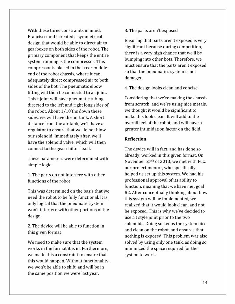
A lack of understanding is demonstrated
through Team 4201’s Leo Robot. The
images below portray that Leo did not
have a mechanism which would shift their
gears. Although this created less
complications/spacing issues, the robot
was only able to travel at a slow speed
with high torque. In turn, they weren’t
able to swerve around defense robots,
travel to the nets quickly, and overall,
increase their chances of having a
successful round. In the image below, you
can see the gearbox that controls the left
side wheels.
17
What you do not see, however, is a way
for gears within this box to shift from low
speed to high speed. That is the main flaw
with this approach, and as explained
earlier, bottlenecked Leo’s winning
potential because it slowed them down
drastically.
This example is significant to the
justification of this design because it
shows that the lack of a pneumatic system
is what bottlenecked Team 4201’s robot
from travelling at high torque and high
speed. Although there are other solutions
to the gear shifting problem, pneumatics
is the only approach which gets the
effective results illustrated in the
comparison against the Sonic Shifter.
What all other solutions fail to do is
unlock the knowledge of pneumatics: one
of the most widely applicable and
effective systems within FRC.
Understanding pneumatics through the
motor shifting approach is very beneficial
not only because it allows our robot to be
quicker, torquier, and more adaptable,
but because this will provide us with the
knowledge to apply pneumatics to ANY
problem presented in the 2014 build
season. We’ve already seen pneumatics’
applicability; a team used it to make a t-
shirt cannon, an arm grabber, and even a
feeding system. Because pneumatics was
capable of being applied to such a wide
range of problems, we know that
pneumatics will be just as adaptable
during Team 4201’s 2014 season.
Whether it be shooting, shifting, or
climbing, pneumatics will lead our team
to success.
Winning
The effort, which has been solid, and
expense, which will only be a minimal jab
to our team’s finances is justifiable in
terms of our market size and plan to
reach the target market. Firstly, it is
justifiable for our market size (40 team
members), because the impact of success
on these members is beyond explainable.
As demonstrated in “The Voices” Team
4201 video, one can see that the team’s
existence and success has motivated
students greatly to pursue careers in
engineering. This proves that any and all
efforts must be taken to ensure that we
are encouraging students to follow this
path. In our case, we are spending a total
of about 400 dollars, and it is quite easy
to say that it is worth 400 dollars to set
students on a pathway towards a
successful career in Engineering. The
establishment of high interest, which will
be a result of our pneumatic shifter, will
help team members stick strong and stay
passionate to Engineering because the
shifter will ensure higher success rates in
Leo. Thus, the higher success rates will
translate into greater encouragement of
team members, as they will not be
disillusioned to pursue engineering in
their future. So too, this shifter will attract
greater attention from sponsors, who will
donate more money in light of our
successes. Once again, these donations
will ensure better resources, and thus,
higher success rates.
18
Element E:
Application of STEM Principles and
Practices
19
I. INVESTIGATION
The main scientific concept (which
includes many within) that needed to be
investigated in order to understand our
project was how a pneumatic system
worked overall. This would include from
the beginning point where the air itself is
developed and where the air transfers to
work in order to perform a specific task.
The science approach was on how the
pneumatic system was put together and
how it worked internally. This included
watching videos on how to set
pneumatics so that a cylinder’s piston
would be pressured out. By first watching
the “Team 2485 Pneumatics Tutorial”
video we got a rough idea on how to put
the pneumatic system together. However,
there were holes in our understanding;
we did not know how the solenoid
worked internally, how it was attached to
the overall system, and how the piston
worked inside the cylinder. We soon
investigated that a solenoid performed
the task of switching direction in which
air flowed, in amounts of seconds through
a small electric charge that had to be
applied to one of the two terminals on the
solenoid itself. The reason the direction of
air flow needed to be switched was
because of the way a piston works inside
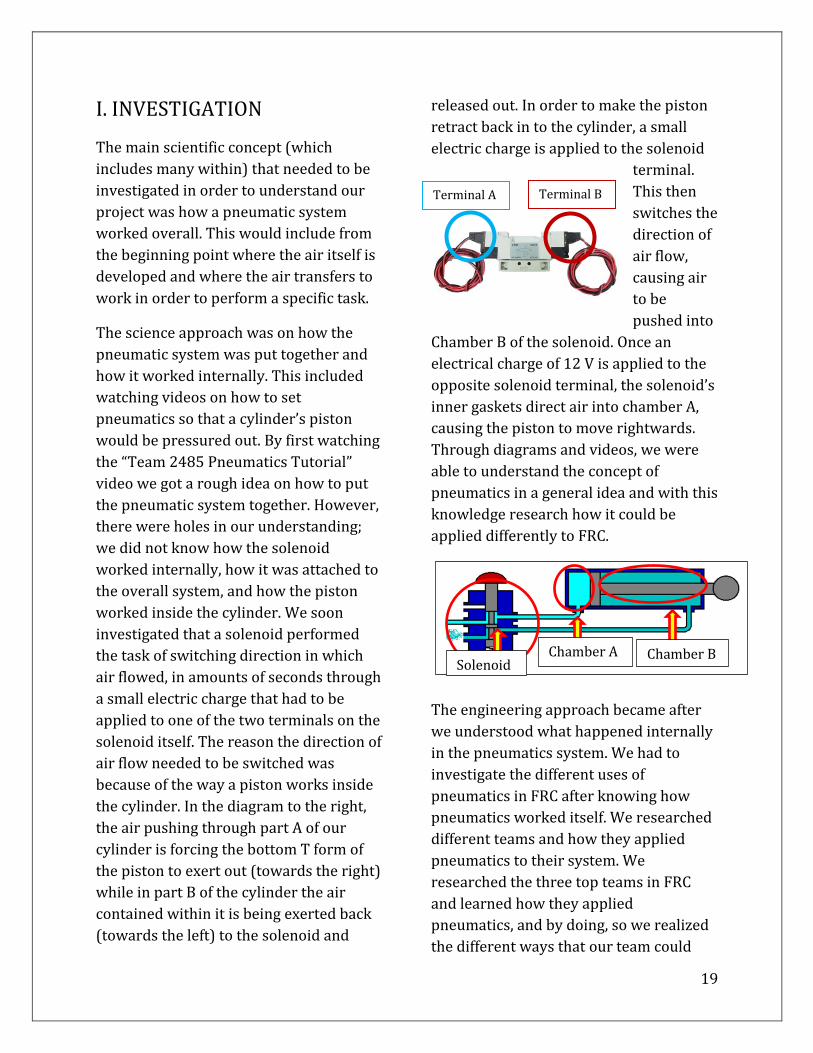
the cylinder. In the diagram to the right,
the air pushing through part A of our
cylinder is forcing the bottom T form of
the piston to exert out (towards the right)
while in part B of the cylinder the air
contained within it is being exerted back
(towards the left) to the solenoid and
released out. In order to make the piston
retract back in to the cylinder, a small
electric charge is applied to the solenoid
terminal.
This then
switches the
direction of
air flow,
causing air
to be
pushed into
Chamber B of the solenoid. Once an
electrical charge of 12 V is applied to the
opposite solenoid terminal, the solenoid’s
inner gaskets direct air into chamber A,
causing the piston to move rightwards.
Through diagrams and videos, we were
able to understand the concept of
pneumatics in a general idea and with this
knowledge research how it could be
applied differently to FRC.
The engineering approach became after
we understood what happened internally
in the pneumatics system. We had to
investigate the different uses of
pneumatics in FRC after knowing how
pneumatics worked itself. We researched
different teams and how they applied
pneumatics to their system. We
researched the three top teams in FRC
and learned how they applied
pneumatics, and by doing, so we realized
the different ways that our team could
Chamber A Chamber B Solenoid
Terminal A Terminal B
20
apply pneumatics to potentially be one of
the winning teams. On element D under
design approaches, you can see more
depth of the result of investigating
different applications of pneumatics
within the top teams. This approach,
which meant analyzing the different uses
of a system is related to Engineering in
that Engineers are constantly reanalyzing
the applicability of a product to its
market. In that same way, we were
analyzing the applicability of pneumatics
to our robot.
II. THE CONCEPTS
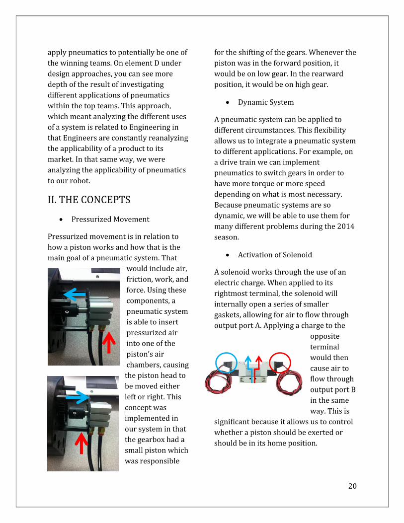
Pressurized Movement
Pressurized movement is in relation to
how a piston works and how that is the
main goal of a pneumatic system. That
would include air,
friction, work, and
force. Using these
components, a
pneumatic system
is able to insert
pressurized air
into one of the
piston’s air
chambers, causing
the piston head to
be moved either
left or right. This
concept was
implemented in
our system in that
the gearbox had a
small piston which
was responsible
for the shifting of the gears. Whenever the
piston was in the forward position, it
would be on low gear. In the rearward
position, it would be on high gear.
Dynamic System
A pneumatic system can be applied to
different circumstances. This flexibility
allows us to integrate a pneumatic system
to different applications. For example, on
a drive train we can implement
pneumatics to switch gears in order to
have more torque or more speed
depending on what is most necessary.
Because pneumatic systems are so
dynamic, we will be able to use them for
many different problems during the 2014
season.
Activation of Solenoid
A solenoid works through the use of an
electric charge. When applied to its
rightmost terminal, the solenoid will
internally open a series of smaller
gaskets, allowing for air to flow through
output port A. Applying a charge to the
opposite
terminal
would then
cause air to
flow through
output port B
in the same
way. This is
significant because it allows us to control
whether a piston should be exerted or
should be in its home position.

21
Space Conservation
When we apply pneumatics to a system
we must make sure that the system works
properly within the given constraints and
parameters. We must consider every
system that might affect the efficiency of
the pneumatic system, and that the
pneumatic system does not interfere with
any of the other working systems around
it. This means that we must chose the
design which best conserves space, and is
why we chose Design #3 for our top
design.
Stress
The maximum amount of stress our
system can handle overall is 125 psi. This
is because the CKD 12V solenoid can only
handle up to 125 psi
and can only work
with 12 V. Without
the solenoid, the system will not work at
all. The solenoid is so crucial to the
system’s function that its ability to work
is completely dependent on it. This is so
because the solenoid allows us to control
the positions of our piston, and if broken,
would keep the piston in one rigid
position. The rigidness would be due to
one of the solenoid pathways to one of its
ports being completely busted open,
causing all air to fill up through that
pathway and to the piston’s chambers.
htt
p:/
/ww
w.a
nd
ymar
k.co
m/p
rod
uct
-p/a
m-2
343
.htm
22
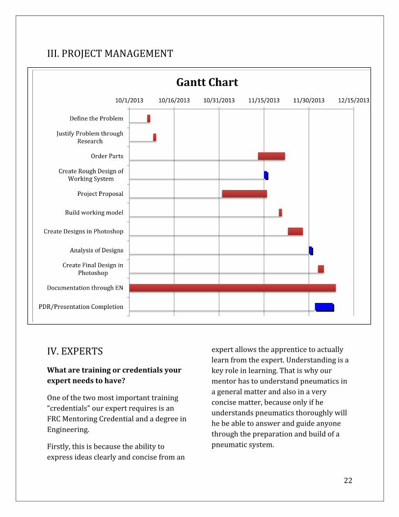
III. PROJECT MANAGEMENT
IV. EXPERTS
What are training or credentials your
expert needs to have?
One of the two most important training
“credentials” our expert requires is an
FRC Mentoring Credential and a degree in
Engineering.
Firstly, this is because the ability to
express ideas clearly and concise from an
expert allows the apprentice to actually
learn from the expert. Understanding is a
key role in learning. That is why our
mentor has to understand pneumatics in
a general matter and also in a very
concise matter, because only if he
understands pneumatics thoroughly will
he be able to answer and guide anyone
through the preparation and build of a
pneumatic system.

23
Our mentor has to have at least a
Bachelor’s degree in Engineering.
Logically a bachelor in the engineering
field means that a person has had
experience with engineering at least three
to four years in that certain field.
Specifically, engineering is having a
scientific theory and applying that theory
to solve a problem that exists. With this in
mind, we know that a person with a
Bachelor in Engineering must know how
to solve a problem mathematically and
also know how to approach a problem by
designing and developing new solutions
to that problem.
It would be even more beneficial if the
mentor/expert had a degree in
Mechanical Engineering (BME). This will
benefit us in that if our mentor has a BME
degree, he/she will understand the
mechanics of different systems, of which
include pneumatic systems. Their
understanding will better our effort by
providing us with any clarifying
knowledge, and thus, keeping our project
going.
V. PROGRAMS
Special computer programs,
technology or equipment you might
use?
Special computer programs that could be
used are programs like CAD, Photoshop
and Robot C.
• CAD- Computer-aided design
Using any program like CAD could fall
into sub-categories like using Inventor.
Essentially what these computer
programs do is develop 3D diagrams that
are specific to what the product will be.
However, the programs themselves can
go more in depth, which means the
program’s output must show materials
needed to do a specific part, specific
dimensions, strains and stresses that can
be applied to the product. Think of the
program’s output as a digitalized version
of what a product will need and how it
will turn out.
• Photoshop
Using Photoshop one could add graphics
to the 3D diagram of the product. Of
course, using Photoshop is the access to
the visual appeal of the product and
adding not only color but texture to the
product overall. By creating a visual
appeal of the product or in pneumatics we
can apply the different brainstorming
solution in which our product will finalize
in. After this we can us Photoshop to add
color to the pneumatic system and
categorize from all of the other systems
that would be applied to the final
graphics. Why should we add color just to
the pneumatic system? When trying to
find a single part of the pneumatic system
once it is integrated with the other
systems of the device, it will be hard to
memorize the position of every detail. By
categorizing them by color one can find a
part and where it is specific to the
pneumatic system just by looking at the
Photoshop version of it. In addition,
Photoshop provides an added level of
24
realism to the product, because it allows
us to crop and insert the photos of the
actual parts. This then leaves us one step
closer to the final presentation of our
product.
• Robotc
Robotc is a computer program designed
for people who want to command
technology to do certain tasks. We can
think of Robotc as being a whole new
different language for people. This
language allows people to write certain
commands for technology to follow. For
example, a computer needs to know that
when a certain key is pressed, a letter
must be written on the screen. This type
of command is done by programming
through similar Robotc computer
programs. A computer knows that when
the key with a symbol “c” is pressed than
the screen should appear with a letter c
and move on to the next symbol that
would be pressed. Robotc is one of the
programs that allows these type of
functions. In pneumatic systems Robotc
will enable us to control the solenoid and
command it to open and close and when it
needs to shift the air to another hole. This
program will also enable us to command
the solenoid to have timing in it so at
what time the air must be switched so
that the piston returns to its “home”
position. This is done simply by using
Robotc to command an electrical charge
of 12V to either one of the Solenoid’s
terminal.
Computer w/ RobotC/Photoshop
A computer that has all the programs
listed above is necessary. Without a
computer, it is physically impossible
write a program that a solenoid would
follow. Diagrams could be done by hand
but the most professional presentation of
diagrams and sketches are done by
computer where every angle and every
material with specific constraints
attached to it. Computers make our lives
easier in color coding specific parts in our
pneumatic systems, and making our
designs closer to reality.
• Power Distribution Board
Having a power distribution board allows
us to have a safety in our solenoid usage.
Essentially what this board does is
distribute the power to each terminal and
have a safety fuse that will ensure that not
too much power or too little power is
inputted into our solenoid. Putting too
much power in the solenoid would either
burn the solenoid’s contacts or disturb its
electromagnetic coils and gaskets. Putting
too little power means the solenoid will
not work at all/work under strain. Thus,
having a power distribution board
ensures quality and safety.
• Battery
A solenoid needs an electrical charge to
work and the only way to apply an
electrical charge is by having a supply of
electricity. The supply of electricity comes
from a battery. Why not use an outlet
power? Batteries help with the
transportation and mobility of the
pneumatic system. By latching a battery

25
to a power distribution board we have
exactly what we need in order to make a
pneumatic system work anywhere and
everywhere instead of having to depend
on an electric outlet of power at all times.
So too, an electrical outlet would only
work with an adapter to 12V.