gendocs.rugendocs.ru/docs/22/21371/conv_1/file1.pdf · preface the board of editors of inorganic...
TRANSCRIPT
INORGANIC SYNTHESES
VOL>UME 111

To
the countless unknown but valiant soldiers of science upon whose labors Inorganic Syntheses are based, this series of volumes is dedicated in the hope that it will ease the toil of future
legions.

PREFACE
The Board of Editors of INORGANIC SYNTHESES has been more than pleased with the reception accorded to Volumes I and I1 of this series. The importance of inorganic chem- istry as a distinctive branch of chemistry, so clearly defined by developments in the Second World War, has not only encouraged and stimulated the Editorial Board to continue its efforts to make available txied and tested pro- cedures for the preparation of inorganic compounds, but has demonstrated beyond question the need for infor- mation of the sort presented in these volumes. The very fact that almost half of the syntheses contained in the present volume were submitted by, or checked in, indus- trial laboratories is evidence of the usefulness of these volumes.
The policies and practices established as the result of experience gained in assembling Volumes I and I1 have been continued. Each procedure has been checked care- fully at some laboratory other than the one from which the original method was submitted. After checking and revision, syntheses were edited and then returned to the original authors for final approval. No synthesis is pub- lished until such approval by the authors has been granted.
As in the past, the syntheses have been arranged on the basis of the Mendeleev periodic classification. An effort has also been made to follow the system of nomenclature adopted in the preparation of Volume 11. Trivial and common names, if widely used in the chemical literature, may have been used in a few cases, especially in the index. To make it possible to use all three volumes more satis- factorily, the index has been set up on a cumulative basis.
It has been felt desirable to continue the policy of presenting brief survey articles dealing with specific sub-
vii

viii PREFACE
jects of interest in the field of inorganic chemistry. It has also been felt desirable to bridge the gap between inorganic and organic chemistry by presenting syntheses of materials which, though organic in nature, are widely used by inor- ganic chemists.
Contributions are now being accepted for publication in Volume IV of this series. All manuscripts, in triplicate, should be sent directly to Professor John C. Bailar, Jr., of the University of Illinois, who will serve as editor-in-chief of Volume IV. In submitting manuscripts, the authors are specifically requested to adhere to the style employed in the publication of the first three volumes. The procedure should be preceded by an introduction and followed by a discussion of physical and chemical properties of the com- pound whose method of preparation has been described. Where analytical methods are sufficiently distinctive to warrant a more extended exposition, detailed directions should also be included. Pertinent references should be placed at the end of the synthesis.
The editors take great pleasure in announcing the elec- tion of Professor E. G. Rochow of Harvard University and Professor G. Therald Moeller of the University of Illinois to membership on the Editorial Board. Janet Scott has accepted membership on the Board, after having served so faithfully and conscientiously as consultant on nomen- clature and indexing for Volumes I1 and 111.
The editor-in-chief is most grateful to his associates on the Editorial Board and to members of the Advisory Board for their help in the preparation of Volume 111. It is also a pleasure to acknowledge the help of Patricia Schloesser and Betty Jane Ogg in the preparation of the manuscript.
The editors will be grateful if readers and users of this and previous volumes will call to their attention anyerrors or omissions.
URBANA, ILL. LUDWIG F. AUDRIETH
Mwch, 1950

PAOE CONTENTS
Preface . . . . . . . . . . . . . . . . . . . . . . . . . . vii
CHAPTER I
1 . Sodium Peroxide &Hydrate . . . . . . . . . . . . . . . . 1
CHAPTER I1
2 . Basic Beryllium Derivatives of Organic Acids . . . . . . . . 4 9 11 12 16 17 21 24
3 . Basic Beryllium Acetate and Propionate . . . . . . . . . . 4 . Strontium Sulfide and Selenide Phosphors . . . . . . . . . .
A . Preparation and Purification of Reagents . . . . . . . . B . Special Techniques . . . . . . . . . . . . . . . . . . C . Preparation of Strontium Compounds . . . . . . . . . . D . Preparation of Infrared-sensitive Phosphors . . . . . . .
5 . Barium Thiocyanate . . . . . . . . . . . . . . . . . . . CHAPTER I11
6 . Boron Chloride and Bromide . . . . . . . . . . . . . . . 27 7 . Aluminum Bromide . . . . . . . . . . . . . . . . . . . 30
CHAPTER IV
8 . Carbon Tetraiodide . . . . . . . . . . . . . . . . . . . 9 . Cyanamide . . . . . . . . . . . . . . . . . . . . . . . 10 . Dicyanodiamide (Cyanoguanidine) . . . . . . . . . . . . . 11 . Aminoguanidonium Hydrogen Carbonate (Aminoguanidine Bi-
carbonate) . . . . . . . . . . . . . . . . . . . . . . 12 . Ammonium Dithiocarbemate . . . . . . . . . . . . . . . 13 . Organosilicon Compounds . . . . . . . . . . . . . . . . . . 14 . Dimethyldichlorosilane (Dimethylsilicon Dichloride) . . . . .
16 . Diphenylsilanediol . . . . . . . . . . . . . . . . . . . . 17 . Germanium(I1) Iodide (Germanium Diiodide) . . . . . . . . 18 . Methylgermanium Triiodide (Methyltriiodogermane) . . . . 19 . The Extraction of Hafnium and Zirconium from Cyrtolite . .
A . Extraction . . . . . . . . . . . . . . . . . . . . . . B . Analytical Methods . . . . . . . . . . . . . . . . . . C . Precipitation of Zirconium-Hafnium Phosphates . . . . . D . Conversion of the Phosphates to Acid-soluble Compounds . E . Fractionation of Zirconium and Hafnium . . . . . . . . F . The Preparation of Low-hafnium Zirconia . . . . . . . .
ix
15 . Vinylchlorosilanes . . . . . . . . . . . . . . . . . . . .
37 39 43
45 48 50 56 58 62 63 64 67 68 69 71 72 74 76

X CONTENTS
CHAPTER V
20 . Nitrogen(V) Oxide (Nitrogen Pentoxide. Dinitrogen Pentoxide.
21 . Hydroxybmmonium Salts . . . . . . . . . . . . . . . . A . Hydroxylammonium Phosphate . . . . . . . . . . . .
Nitric Anhydride) . . . . . . . . . . . . . . . . . . . 78 81 82 83 83
22 . The Poly- and Mctaphosphates and the Strong Phosphoric Acids 85 23 . Pyrophosphoric Acid (Diphosphoric Acid) - . . . . . . . . . 96
98 A Disodium Dihydrogen Pyrophosphrttc 99
100 101
26 . Sodium Metaphosphates . . . . . . . . . . . . . . . . . 103 A . Sodium Trimetaphosphate . . . . . . . . . . . . . . . 104
27 . Sodium Monofluophosphate . . . . . . . . . . . . . . . . 106 28 . Silver Monofluophosphate . . . . . . . . . . . . . . . . 109 29 . Hexafluophosphates of Sodium, Ammonium. and Potassium . 111 30 . Ammonium Metavanadate . . . . . . . . . . . . . . . . 117
CHAPTER VI
B . Hydroxylammoniurn Arsenate . . . . . . . . . . . . . C . Hydroxylammonium Oxalate . . . . . . . . . . . . . .
24 . Sodium Pyrophosphates (Sodium Diphosphates) . . . . . . .
B . Tetrasodium Pyrophosphate . . . . . . . . . . . . . . 25 . Sodium Triphosphate (Sodium Tripolyphosphate) . . . . . .
. . . . . . . . . . .
B . Sodium Polymetaphosphate (Graham’s Salt) . . . . . . 104
31 . Sulfur(V1) Fluoride (Sulfur Hexafluoride) . . . . . . . . . . 119
33 . Selenium(1V) Oxide (Selenium Dioxide) . . . . . . . . . . 127 34 . Selenium(1V) Oxychloride . . . . . . . . . . . . . . . . 130 35 . Crystalline Selenic Acid . . . . . . . . . . . . . . . . . 137 36 . Tellurium(1V) Chloride (Tellurium Tetrachloride) . . . . . . 140 37 . Tellurium(1V) Oxide (Tellurium Dioxide) . . . . . . . . . . 143 38 . Telluric Acid . . . . . . . . . . . . . . . . . . . . . . 145 39 . Chromium(I1) Acetate (Chromous Acetate) . . . . . . . . . 148 40 . Anhydrous Chromium(I1) Chloride (Chromous Chloride) . . 150 41 . Hexamminechromium(II1) Nitrate . . . . . . . . . . . . . 153 42 . Chromium Hexacarbonyl . . . . . . . . . . . . . . . . . 156 43 . Potassium Octacyanomolybdate(1V) 2-Hydrate (Potassium
Molybdocyanide Dihydrate) . . . . . . . . . . . . . . 160
45 . Uranium(1V) Oxalate . . . . . . . . . . . . . . . . . . 166 46 . Potassium Tetraoxalatouranate(1V) . . . . . . . . . . . . 109
32 . Disulfur Pentoxydichloride (Pyrosulfuryl Chloride) . . . . . . 124
44 . Tungsten(VI) Chloride (Tungsten Hexachloride) . . . . . . 163
CHAPTER VII 47 . Anhydrous Metal Fluorides . . . . . . . . . . . . . . . . 171
A . Nickel(I1) Fluoride . . . . . . . . . . . . . . . . . . 173 B . Cobalt(II1) Fluoride . . . . . . . . . . . . . . . . . 175

CONTENTS xi
C . Silver(I1) Fluoride . . . . . . . . . . . . . . . . . . 176 D . Carbon Tetrafluoride . . . . . . . . . . . . . . . . . 178 E . Tantalum(Niobium) (V) Fluoride [Tantalum (Niobium)
Pentafluoride] . . . . . . . . . . . . . . . . . . . 179 F . Tungsten(V1) Fluoride (Tungsten Hexafluoride) . . . . . 181
48 . Bromine(II1) Fluoride (Bromine Trifluoride) . . . . . . . 184 49 . Rhenium(V1) Oxide (Rhenium Trioxide) . . . . . . . . . . 186 50 . Rhenium(VI1) Oxide (Dirhenium Heptoxide) . . . . . . . . 188
CHAPTER VIII
51 . Anhydrous Iron(II1) Chloride (Ferric Chloride) . . . . . . . 191 52 . Hexamminenickel(I1) Bromide and Hexamminenickel(I1)
Iodide . . . . . . . . . . . . . . . . . . . . . . . . 194 53 . Bis(N,N'-Disalicylalethylenediamine). ~.Aquodicobalt(II)
(Bis[ N . N'-bis (0- h ydroxy ben z y1idine)ethylenediaminel-p- aquodicobalt(I1)) . . . . . . . . . . . . . . . . . . . 196
Index of Contributors . . . . . . . . . . . . . . . . . . . . 203
Subject Index . . . . . . . . . . . . . . . . . . . . . . . . 205
Formula Index . . . . . . . . . . . . . . . . . . . . . . . 221

CHAPTER I
See also: Pyrophosphor ic acid, synthesis 23
Crystalline selenic acid, synthesis 35
Telluric acid, synthesis 38 Disodium dihydrogen py-
rophosphate, synthesis 24A
Tetrasodium pyrophos- phate, synthesis 24B
Sodium t r i p hos p h a t el synthesis 25
Sodium trimetaphos- phate, synthesis 26A
Sodium polymetaphos- phate, synthesis 26B
Sodium monofluophosphate, syn- thesis 27
Sodium hexafluophosphste, syn- thesis 29
Potassium hexsfluophosphate, synthesis 29
Potassium octacyanomolybdate (IV) 2-hydrate, synthesis 43
Potassium tetraoxalatouranate (IV), synthesis 46
Silver monofluophosphate, synthe- sis 28
Silver(I1) fluoride, synthesis 47C
1. SODIUM PEROXIDE 8-HYDRATE
SUBMITTED BY R. A. PENNEMAN* CIIECXED BY A. D. F. ToYt
Hydrates of sodium peroxide may be prepared by (1) the slow evaporation of a cold aqueous solution of sodium peroxide ;I (2) the slow action of water vapor on solid sodium peroxide ;2 (3) the electrolysis of aqueous sodium hydroxide at temperatures between - 10 and Oo,s and (4) precipitation from a cold solution of sodium hydyoxide and hydrogen peroxide by meins of alcohol.
The method outlined below is a modification of the last mentioned of these procedures and yields a chemically pure product. The success of this method depends upon the use of an excess of sodium hydroxide, since no precipitate is
* University of Illinois, Urbana, Ill. t Victor Chemical Works Research Laboratory, Chicago Heights, Ill,
1
Inorganic Syntheses, Volume 111 Edited by Ludwig F. Audrieth
Copyright © 1950 by McGraw-Hill Book Company, Inc.

2 INORGANIC SYNTHESES
obtained when hydrogen peroxide is present in excess. However, it was found that the amount of water in the hydrate depends upon the temperature at which precipita- tion is carried out. The directions that follow give the &hydrate consistently, whereas a product analyzing almost exactly for Na202.11H20 is formed when hydrogen peroxide is added to a saturated sodium hydroxide solution at 0".
Procedure
Ten grams of carbonate-free sodium hydroxide is dis- solved in 25 ml. of water in a stoppered Erlenmeyer flask and cooled to 15". Ten grams of a 30 per cent solution of hydrogen peroxide (corresponding to a mol ratio of NaOH: HzOz = 2.83:l) is added slowly with constant stirring at a rate such that the temperature does not rise above 18". Sixty milliliters of 95 per cent alcohol (cooled to 15") is added; the flask is then stoppered and shaken vigorously. The solution is allowed to stand about 44 hour, the super- natant liquid is decanted, and the washing is repeated with two 60-ml. portions of cold alcohol. The white crystals are filtered with suction on a hardened filter paper and washed with ether. The compound is transferred quickly to a desiccator containing sulfuric acid (not in vacuo) and kept in a cold chest for 10 hours at a temperature not above 15". The yield is 18 g. (92 per cent based on Hz02). The product may be preserved for a limited period of time in the ice chest.
Analysis
Sodium (reported as Na20) was determined by hydrolysis of a sample and titration with a standard acid. Peroxide oxygen was determined by dissolving a weighed sample in an excess of standard cerium(1V) nitrate solution and titrating the excess cerium(1V) ion with iron(I1) sulfate using o-phenanthroline as indicator. And. Calcd. for Na2O2.8H20: NazO, 27.88; 0 (peroxide) 7.2. Found: Na20, 27.92; 0, 7.11.

SODIUM PEROXIDE %HYDRATE 3
Properties
The %hydrate is a white, crystalline powder which reacts readily with carbon dioxide, hence must be kept from con- tact with the atmosphere. It melts in its own water of crystallization at 30" and decomposes to yield oxygen. If kept for a long period over sulfuric acid in a vacuum desic- cator, the 8-hydrate loses 6 molecules of water to form the 2-hydrate, Naz0~-2Hz0.
References
1. HARCOURT: J . Chem. Soc., 14,278 (1862). 2. JOUBERT: Compt. rend., 132, 86 (1901). 3. German patent 245531 (1911). 4. FAIRLY: J . Chem. Soc., 31, 125 (1877). 6. WALDEN, HAYMETT, and CHAPMAN: J . Am. Chem. SOC., 3908 (1931).

CHAPTER I1
2. BASIC BERYLLIUM DERIVATIVES OF ORGANIC ACIDS
BY THERALD MOELLER*
An apparently unique property of beryllium is its ten- dency to form so-called “basic” derivatives of a number of organic acids. These compounds correspond in composi- tion to the general formula BerO(RC00)6 (R = hydrogen or organic radical) and are, in general, remarkably stable. In fact, the tendency toward their formation is so pro- nounced that the corresponding “normal ” beryllium salts can be prepared only with difficulty or not a t all. Best known of these compounds is the basic acetate, a material that was first discussed critically by Urbain and Lacombel in 1901. A number of other compounds of the series have been described by Lacombc, Tanatar and Kurowski, Glassmann, Bragg and Morgan, Morgan and Astbury, and Feild.9 A comprehensive summary of the preparation and properties of these substances is given in Gmelin’s “ Handbuch der anorganischen Chemie.”’
Preparation. Listed methods of preparation are most extensive for the basic acetate. Methods for the prepara- tion of this compound, however, are generally applicable to the other members of the series.
1. Action of Organic Acid on Beryllium Oxide or Hydrox- ide. This method has been used for the preparation of the majority of the basic derivatives, the most notable excep- tion being the formate. Usually, it amounts to treatment of the hydroxide with the appropriate acid, heating until reaction is complete, evaporating to a solid or oily product,
University of Illinois, Urbana, Ill. 4
Inorganic Syntheses, Volume 111 Edited by Ludwig F. Audrieth
Copyright © 1950 by McGraw-Hill Book Company, Inc.
BASIC BERYLLIUM DERIVATIVES OF ORGANIC AClDS 5
extrwting the basic beryllium compound with a solvent such as chloroform or petroleum ether, and crystallizing from that solvent.
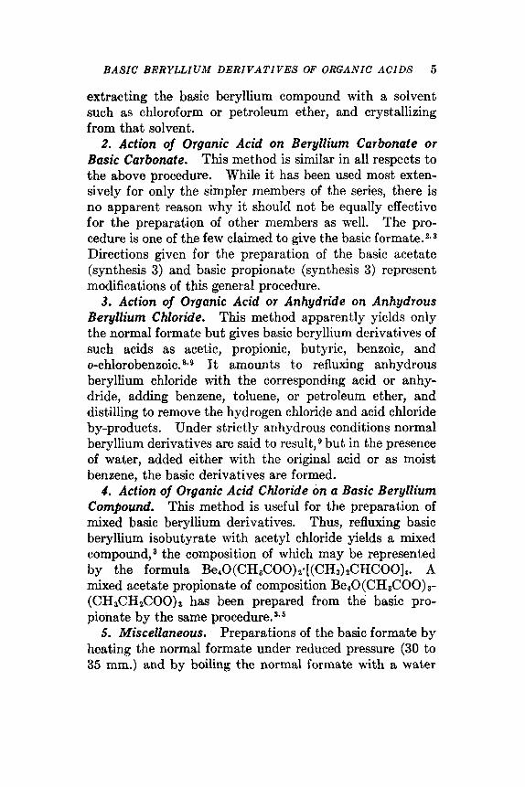
2. Action of Organic Acid on Beryllium Carbonate or Basic Carbonate. This method is similar in all respects to the above procedure. While it has been used most exten- sively for only the simpler members of the series, there is no apparent reason why it should not be equally effective for the preparation of other members as well. The pro- cedure is one of the few claimed to give the basic f ~ r m a t e . ~ ' ~ Directions given for the preparation of the basic acetate (synthesis 3) and basic propionate (synthesis 3) represent modifications of this general procedure.
3. Action of Organic Acid or Anhydride on Anhydrous Beryllium Chloride. This method apparently yields only the normal formate but gives basic beryllium derivatives of such acids as acetic, propionic, butyric, benzoic, and o-chloroben~oic.~~~ It amounts to refluxing anhydrous beryllium chloride with the corresponding acid or anhy- dride, adding benzene, toluene, or petroleum ether, and distilling to remove the hydrogen chloride and acid chloride by-products. Under strictly anhydrous conditions normal beryllium derivatives are said to r e ~ u l t , ~ but in the presence of water, added either with the original acid or as moist benzene, the basic derivatives are formed.
4. Action of Organic Acid Chloride on a Basic Beryllium Compound. This method is useful for the preparation of mixed basic beryllium derivatives. Thus, refluxing basic beryllium isobutyrate with acetyl chloride yields a mixed compound,a the composition of which may be represented by the formula Be40(CH3COO)z~[(CH3)2CHCOO]4. A mixed acetate propionate of composition Be10(CH3COO) 3-
(CH&H2C00)3 has been prepared from the basic pro- pionate by the same procedure.3*6
5. Miscellaneous. Preparations of the basic formate by heating the normal formate under reduced pressure (30 to 35 mm.) and by boiling the normal formate with a, water

6 INORUANIC SYNTHESES
suspension containing the calculated amount of beryllium carbonate have been described.
In addition to the compounds listed in Table I, corre- sponding basic derivatives of the following acids have been reported : crotonic ; isocrotonic ; levulinic ; succinic ; cyano- acetic ; mono-, di-, and trichloroacetic ; monobromoacetic ; monochloro- and monobromopropionic ; lactic ; glycolic ; ethyl- and pheriylglycolic (a-hydroxybutyric and mandelic, respectively) ; and salicylic. Confirmatory evidence for the identities of most of these is completely lacking.
Properties. The basic beryllium compounds are non- electrolytes and possess all of the properties of purely cova- lent substances. They are low-melting, low-boiling mate- rials that generally sublime or distill without decomposition. They are usually insoluble in water but soluble in such organic solvents as chloroform, ether, petroleum ether, benzene, toluene, and the alcohols. Physical constants, where known, are given in Table I. Molecular weights, as determined by vapor density' and cryoscopic 2*3 measure- ments, correspond to those of monomolecular compounds of composition BerO(RCOO) 6.
Chemically, the basic beryllium compounds are stable toward heat, toward oxidation except under very drastic conditions (e.g., boiling with nitric acid), and toward cold water. Treatment with boiling water usually effects hydrolysis slowly ; treatment with mineral acids normally yields the corresponding beryllium salt and the free organic acid.
Structure. Older concepts picturing the basic beryllium compounds as derivatives of condensed acids or as struc- tural analogs of the true basic salts of the other elements have been discarded in favor of unitary structures com- parable with those ascribed to other strictly covalent compounds.
The x-ray studies of Bragg and MorganK on the basic acetate indicate a central oxygen atom surrounded tetra- hedrally by the four beryllium atoms, each edge of the

TA
BL
E I.
PR
OP
ER
TIE
S
OF
BASIC BE
RY
LL
IUM
D
ER
IVA
TIV
ES
Der
ivat
ive
...
For
mat
e..
....
....
....
...
Ace
tate
. ...
....
....
....
....
....
....
....
..
....
....
....
Isob
utyr
ate
....
....
....
....
D
iace
tatc
Tet
rais
obut
yrat
e ...
....
....
....
Piv
alat
e. .
....
....
....
....
....
....
....
. B
enzo
ate ..
....
....
....
....
....
....
....
. 0-
Chl
orob
enzo
ate .
....
....
....
....
....
..
For
mul
a
Bcr
O(H
C00
)s
Be4
0 (C
HsC
OO
) 6 B
e40(
CH
&H
&00
)s
Be4
0(C
HsC
OO
)~(C
H&
H2C
00) 3
Be4
0[ (C
Hz)
&H
CO
O]~
Be4
0[ (C
Hn)
zCH
CH
~C
OO
]~
Be4
0 (C
&C
OO
) E
Be4
0 (C
lC&
CO
O)
Ber
O(C
HaC
HzC
HzC
00)s
13~4
0(C
HsC
OO
)z[ (C
Ha)
&H
CO
Ol
Bcr
O[(
CH
daC
CO
Ols
Mel
ting
po
int,
"C
Subl
imes
137.5-138
140-142
25-27
88-89
--
285-286
- 15
..
..
..
..
163
255-256
317-318
Boi
ling
poi
nt,
"C
330-331
339-341 (19 m
m.)
330
239 (19 m
m.)
336-337
35 1
254 (19 m
m.)
..
....
....
....
.
ta a Q 2
Den
sity
, +
i? z g.
/ml.
b
h
1.39
~ a 2 1.25
Y
cr
T
1.14
h
G2
8 INORGANIC SYNTHESES
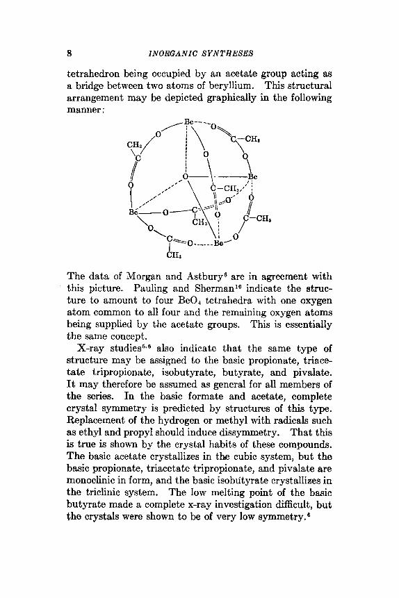
tetrahedron being occupied by an acetate group acting as a bridge between two atoms of beryllium. This structural arrangement may be depicted graphically in the following manner :
The data of Morgan and Astburys are in agreement with this picture. Pauling and Sherman'O indicate the struc- ture to amount to four Be04 tetrahedra with one oxygen atom common to all four and the remaining oxygen atoms being supplied by the acetate groups. This is essentially the same concept.
X-ray st.udies6*6 also indicate that the same type of structure may be assigned to the basic propionate, triace- tate tripropionate, isobutyrate, butyrate, and pivalate. It may therefore be assumed as general for all members of the series. In the basic formate and acetate, complete crystal symmetry is predicted by structures of this type. Replacement of the hydrogen or methyl with radicals such as ethyl and propyl should induce dissymmetry. That this is true is shown by the crystal habits of these compounds. The basic acetate crystallizes in the cubic system, but the basic propionate, triacetate tripropionate, and pivalate are monoclinic in form, and the basic isobutyrate crystallizes in the triclinic system. The low melting point of the basic butyrate made a complete x-ray investigation difficult, but the crystals were shown to be of very low symmetry.6

BASIC BERYLLIUM ACETATE AND PROPIONATE 9
1. 2. 3. 4. 5. 6. 7.
8. 9. 10.
References
URBAIN and LACOMBE: Compt. rend., 133, 874 (1901). LACOMBE: ibid., 134, 772 (1902). TANATAR and KUROWSKI: J . Elms. Phys. Chem. SOC., 39,936 (1907). GLASSJMNN: Ber., 41, 33 (1908). BRAGQ and MOROAN: Proc. Roy. SOC. (London), A104,437 (1923). MORQAN and AST~TJRY: ibid., A112, 441 (1926). GMELIN: “Handbuch der anorgsnischen Chcmie,” So. 26, pp. 150-155,
Verlag Chemie, C.m.b.H., Berlin, 1930. FUNK and R~MIIIR: %. anorg. allgem. Chem., 239,288 (1938). FEILD: J . Am. Chem. SOC., 61, 1817 (1939). PAULING and SHERYAX: PTOC. Nat. Amd. Sci., 20,340 (1934).
3. BASIC BERYLLIUM ACETATE AND PROPIONATE
3 xBeO.yBeCOa + (x + y)RCOOH +
3 ‘3 BeaO(RCOO)s + yC0, + 4 (x + y)H,O
SL~MITTED BY THERALD MOELLER,* ALVIN J. COHEN,* AND ELLIOT MAR- VELL+
CHECKED BY P. s. R A K E R i A N D D. F. S M I T H t
The basic acetate and propionate of beryllium are pre- pared most conveniently from a reactive form of the basic carbonate. The composition and the reactivity of the starting material are variable, and it may therefore be necessary to prepare the so-called “basic ” carbonate from some convenient source of beryllium, especially if the avail- able “ carbonate” dissolves with difficulty in either hot acetic or propionic acid. For properties of these com- pounds see page 7.
Procedure
A. BASIC BERYLLIUM ACETATE
Be10(CH3COO)
Forty grams of basic beryllium carbonate is stirred with 80 ml. of glacial acetic acid on the hot plate until carbon
* University of Illinois, Crbana, Ill. t University of Vermont, Burlington, Vt.

10 INORGANIC SYNTHESES
dioxide is no longer evolved.* When reaction is complete, some of the basic acetate may separate as white, semitrans- parent crystals. If reaction is incomplete, an amorphous- appearing white residue remains. The solution is cooled to room temperature, and the crude basic beryllium acetate that crystallizes is removed by suction filtration and air- dried. The product is treated with 60 to 80 ml. of chloro- form and any undissolved material removed by filtration. The chloroform solution is evaporated on the steam bath. The colorless octahedra of the basic acetate are freed of residual solvent in a vacuum desiccator. The product melts at 284' (uncorr.) and sublimes without residue under reduced pressure. The yield is 28 g. (65 per cent, based upon a basic carbonate containing 26.6 per cent beryllium oxide).t Anal. Calcd. for Be40(CH3COO)6: C, 35.46; H, 4.46. Found: C, 35.70; H, 4.82.
B. BASIC BERYLLIUM PROPIONATE
Be40(CH3CH2C00)a
Twenty-five grams of basic beryllium carbonate is treated with 125 ml. of propionic acid in a 400-ml. beaker. When evolution of carbon dioxide has ceased, the solution is trans- ferred to a porcelain evaporating dish and evaporated on a
* If the basic carbonate used does not react completely with acetic acid or if only beryllium oxide is available as starting material, conversion to freshly precipitated basic carbonate by the following procedure must p r e cede treatment with acetic acid. Ten grams of beryllium oxide or 40 g. of the basic carbonate is dissolved in 50 ml. of concentrated sulfuric acid and the solution diluted to 500 ml. with distilled water. Aqueous ammonia (5N) is added until the solution is basic to litmus. The resulting suspension is clarified by digestion on the steam bath, and the precipitated hydroxide is removed by suction filtration and air-dried. The product is powdered in a mortar and suspended in 200 ml. of water containing 5 ml. of 5 N ammonia. The suspension is saturated with carbon dioxide either by addition of a few pieces of solid carbon dioxide or by bubbling in the gea. The container is stoppered and allowed to stand overnight. The resulting basic carbonate is removed by suction filtration and air-dried. It is then powdered and dried further in a desiccator.
t Calculation of percentage yield must be based upon the analytically determined beryllium content of the basic carbonate.

STRONTIUM SULFIDE A N D SELENIDE PHOSPHORS 11
hot plate at 130 to 140”. When the cooler portions of the liquid begin to deposit crystals, the dish is allowed to cool. The solid cake of crude product is broken up and ground to a fine powder in a mortar. The powder is dissolved in 300 ml. of hot petroleum ether (b.p. 80 to loo”), and the filtered solution allowed to crystallize overnight in the refrigerator. The colorless crystals are removed by suction filtration and dried in the air. The yield is 45 g. (85 per cent, based on a starting material containing 15.4 per cent beryllium). The crystals melt at 137.5 to 138”, with preliminary softening at 134”. Anal. Calcd. for Be4O- (CH3CH2COO)6: C, 44.07; H, 6.17. Found: C, 44.18; H, 6.31.
4. STRONTIUM SULFIDE AND SELENIDE PHOSPHORS
SUBMITTED BY R. WARD,* R. K. OSTERHELD,* AND R. D. ROSENSTEI“ CHECKED BY D. w. LYONt AND E. L. P O O R t
The alkaline earth sulfides were among the earliest known synthetic phosphorescent materials. Recent work by Urbach’ has shown that some of these substances exhibit the property of energy storage to a phenomenal degree and that this property may be developed by the addition of small quantities of two impurity cations or “activators.” One of the activators serves to furnish electrons that may be promoted to higher energy states in the lattice by absorp- tion of short-wave-length visible or ultraviolet light. This process is called “excitation.” The other activator intro- duces potential wells in which some of the excited electrons are trapped. The potential barriers opposing the liberation of the electrons from these traps are high enough so that very few electrons are released by thermal energy at room temperature. Exposure to infrared radiation (about 1 p) , however, effectively releases the trapped electrons with
* Polytechnic Institute of Brooklyn, Brooklyn, N.Y. t Chemical Division, Pigments Department, E. I. du Pont de Nemours
and Company, Newport, Del.

12 INORGANIC SYNTHESES
consequent emission of visible light. This is known as “ stimulation.”
Several complementary pairs of activators have been used, but the most effective are those consisting of cerium- samarium and europium-samarium, the samarium ions furnishing the trapping centers. Phosphors of this type are best prepared from the pure alkaline earth sulfides or selenides by introducing the activators with the aid of a flux such as an alkaline earth halide or lithium fluoride.
Some of the procedures outlined below have been described p r e v i o ~ s l y . ~ ~ They are designed for the prepa- ration of phosphors that are to be used for quantitative studies of luminescence. Details are presented for the preparation of strontium nitrate, strontium chloride, stron- tium sulfate, and strontium selenite in a state of high purity; for the reduction of the sulfate to the sulfide and the selenite to the selenide; and for the conversion of the sulfide and the selenide into typical infrared-sensitive phosphors.
The necessity for unusual care in the preparation of reagents and the handling of all materials cannot be over- emphasized if reproducible results are to be obtained. While products having luminescent properties sat,isfactory for some practical uses can be obtained without recourse to the detailed procedures described here, such methods must be employed whenever reliable and reproducible mate- rials are desired. For this reason, the preparation and purification of some of the reagents are first described along with several special techniques that have been found to be both useful and desirable.
Procedure
A. PREPARATION AND ~?URIFICATIOX OF REAGENTS
All glass and silica equipment employed should be cleaned with boiling nitric acid and washed with distilled water. Final washing should be made with twice distilled water.

STROiVTIUM SULFIDE A N D SELENIDE PHOSPHORS 13
The use of chromic acid cleaning solution must be avoided to prevent introduction of chromium. Flasks should be kept covered with inverted beakers to eliminate contamina- tion from dust.
After the first step in the purification operations, any water that is used must be twice distilled, the second distil- lation being carried out in all-glass stills.
Where purified nitric acid is specified the purification is achieved by distilling reagent-grade nitric acid in a silica
Glass wah
Quarfz condenser hbe
Dust cap
Fro. 1. Nitric acid still.
still or in a glass still fitted with a silica condenser as shown in Fig. 1. The dust cap depicted in Fig. 1 may be made by appropriately cutting a round-bottomed flask.
The apparatus for preparing pure hydrochloric acid and for generating gaseous hydrogen chloride is shown in Fig. 2 (see also synthesis 34).
The ammonium hydroxide solution is prepared as needed by passing tank ammonia into doubly distilled water to saturation.
Selenium(1V) oxide is purified by three successive sub- limations in the apparatus illustrated in Fig. 36 (see also synthesis 33). The sublimation chamber A is maintained

14 INORGANIC SYNTHESES
at 250 to 300’ and a slow stream of a dry mixture of oxygen and oxides of nitrogen is passed through the system to prevent decomposition and to sweep the vapors into the condenser B. The oxides of nitrogen are prepared by drop- ping a saturated solution of sodium nitrite into 6 N hydro- chloric acid.
7- tube pressure I equahzer
h I ” I t *Hi2 dehery
, Separahry funnel
. Su/phur/c acid
FIG. 2. Hydrogen chloride generator.
Purified nitrogen is obtained by removing oxygen and water vapor from commercial tank nitrogen. This can be accomplished by passing the gases through a hot tube (375 to 400”) containing copper, and then through drying towers packed with barium oxide or phosphorus(V) oxide. A n active form of copper especially satisfactory for removal of oxygen is obtained by reduction of the “wire form” of copper(I1) oxide with hydrogen at about 360”.
Hydrogen sulfide is treated by bubbling the gas through a saturated barium hydroxide solution to remove other volatile acidic hydrides and then through glass wool to remove entrained material. An apparatus for treating

STRONTIUM SULFIDE A N D SELENIDE PHOSPHORS 15
solutions with hydrogen sulfide is shown in Fig. 4. When the gas is to be used to treat strontium sulfide it must be dried over phosphorus(V) oxide.
Ammonia is dried by passing the gas through towers
Made ofkym fubiny .:. Gkas wool
B A +‘I
FIG. 3. Apparatus for the purification of selenium(1V) oxide by sublimation.
Tank -----
Fro. 4. Apparatus for treating solutions with hydrogen sdide.
filled with porous barium oxide. Hydrogen is dried using phosphorus(V) oxide or barium oxide as the desiccant. Where a definite rate.of gas flow is specified, the rate may be measured by means of a capillary manometer type of flowmeter, but there are other equally suitable types.

16 INORGANIC SYNTHESES
B. SPECIAL TECHXIQUES A useful apparatus for filtering solutions is illustrated in
Fig. 5. A mat of previously washed filter paper pulp deposited over the fritted-glass surface helps to retain finely
FIG. 6. Filtering apparatus.
FIG. 6. Apparatus for effecting the removal of liquid from a precipitate.
divided precipitates and makes the cleaning of the funnel easier as practically all of the precipitate is removed with the mat. A flask other than the one intended as a rcceiver for the solution to be filtered is used to hold the funnel during the preparation and washing of the filter mat.
The “inverted filtration ” technique employed to wash a precipitate is illustrated in Fig. 6. The liquid to be removed is drawn off through a sintered-glass dispersion
STRONTIUM SULFIDE A N D SELENIDE PHOSPHORS 17
disk. The disk is kept just above the surface of the settled precipitate until virtually all of the supernatant liquid has been removed. It is then pressed down into the precipitate to remove the remaining liquid. These procedures lessen considerably the danger of contamination from dust.
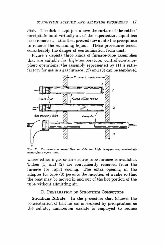
Figure 7 depicts three kinds of furnace-tube assemblies that are suitable for high-temperature, controlled-atmos- pherc operat,ions: the assembly represented by (1) is satis- factory for use in a gas furnace; (2) and (3) can be employed
a @---Furnace wa//s-----
Y Fro. 7. Purnacctube assemblirs suitable for high temperature, controlled- atmosphere operations.
where either a gas or an electric tube furnace is available. Tubes (1) and (2) are conveniently removed from the furnace for rapid cooling. The extra opening in the adapter for tube (3) permits the insertion of a rake so that the boat may be moved in and out of the hot portion of the tube without admitting air.
C. PREPARATION OF STRONTIUM COMPOUNDS Strontium Nitrate. In the procedure that follows, the
concentration of barium ion is lessened by precipitation as the sulfate; ammonium oxalate is employed to reduce

18 INORGANIC SYNTHESES
calcium-ion impurity. The heavy-metal contaminants are removed by precipitation with hydrogen sulfide. Bromine serves to oxidize iron(I1) ion and to destroy any oxalate remaining in the solution, and nitric acid to oxidize sulfide ion. The strontium nitrate is finally purified by'recrystal- lieation. It should be noted that the solution is not filtered after each precipitation. The bulkier precipitates are left to carry down those substances which tend to be colloidal in nature.
One hundred sixty-eight milliliters of reagent-grade nitric acid (18 N ) is added slowly to 200 g. of reagent-grade strontium carbonate suspended in 455 mLof distilled water in a 1-1. round-bottomed flask. The mixture is heated for a few minutes on a sand bath or by a heating mantle. A small amount of carbonate should remain undissolved. Approximately 1 ml. of reagent-grade sulfuric acid (36 N ) is added to the warm solution which is then heated to boil- ing, removed from the sand bath and immediately treated with hydrogen sulfide for about 15 minutes. The solution is again heated to boiling on the sand bath, allowed to cool, and filtered after standing for several hours. This filtra- tion and those which follow should be carried out as described in the section on special techniques and illustrated in Fig. 5.
The pH of the solution is adjusted to 7* by addition of freshly prepared ammonium hydroxide solution. About 9 ml. of a saturated solution of reagent-grade ammonium oxalate is added, the solution is boiled, and, if necessary, the pH is again adjusted to 7. The hot solution is saturated with purified hydrogen sulfide, allowed to stand for several hours, and then filtered. By the addition of distilled nitric acid to the filtrate, the pH is lowered to 2, and 0.3 ml. of reagent-grade bromine is added to the solution, which is then boiled to remove excess bromine. The solution is just neutralized with freshly prepared ammonium hydroxide, treated with hydrogen sulfide while hot, and, after raising
* pH paper is used to determine pH throughout the preparation.

STRONTIUM SULFIDE A N D SELENIDE PHOSPHORS 19
the pH to 8 with fresh ammonium hydroxide, is again treated with hydrogen sulfide for 1.5 minutes. The mixture is then boiled and filtered when the precipitate has settled.
From 1 to 1.8 ml. of distilled nitric acid is next added to the filtrate to Iower the pH to about 2; upon boiling the solution, a deposit of sulfur is obtained. After standing for several hours this is removed by filtration.
The resulting strontium nitrate solution is now concen- trated by evaporation until bumping commences. It is cooled and nitric acid distilled into the solution until pre- cipitation ceases. The supernatant liquid is removed as completely as porsible, employing the technique shown in Fig. 6. The crystalline mass is dissolved in the smallest possible quantity of doubly distilled water and the solution is filtered. The crystallization procedure is repeated twice, yielding as the final product a saturated solution of thrice recrystallized strontium nitrate. This solution is diluted to 500 ml. with doubly distilled water and is used for the precipitation of strontium sulfate or strontium selenite.
Strontium Sulfate. The 500 ml. of strontium nitrate solution is heated to boiling in a round-bottomed flask and strontium sulfate is precipitated by the slow addition of st
solution of 50 ml. of reagent-grade sulfuric acid (36 N ) in 65 ml. of distilled water. When the precipitate has settled, the supernatant liquid is removed by the inverted filtration technique and the precipitate washed successively with five 200-ml. portions of hot, doubly distilled water. For the last washing the precipitate should be transferred to a beaker. It may then be removed more easily after drying for several hours at 200". The strontium sulfate should not contain more than 20 parts per million of nitrate ion using diphenylaminesulfuric acid reagent as a colorimetric test.' The yield is about 120 g.*
* The yield obtained depends primarily upon how much of the strontium nitrate is recovered in the three crystallizations. A considerably higher yield is possible, but if the degree of recovery becomes too high the quality of the product may suffer.

20 INORGANIC SYNTHESES
Strontium SuEde. A weighed silica-glass boat is filled with the dry strontium sulfate and heated in a stream of sulfur dioxide and oxygen for 30 minutes at 980" using the assembly depicted in Fig. 7. The boat is then removed and weighed. It is replaced in the firing tube from which the air is swept by a stream of nitrogen. Dry hydrogen is then passed through the tube at about 200 ml. per minute while the charge is heated to 980" for 2 hours. The charge is cooled in an atmosphere of purified nitrogen. The weight loss should be close to the theoretical (34.84 per cent). The product is ground in a clean, dry, porcelain mortar in a dry box and returned to the silica-glass boat. It is then heated in a stream of purified hydrogen sulfide at 1000" for about 30 minutes, cooled in purified nitrogen and stored in a glass-stoppered bottle in a desiccator over barium oxide.
A solution of 77 g. of sublimed selenium(1V) oxide in 154 ml. of distilled water is added to 500 mI. of pure strontium nitrate solution prepared as pre- viously described. The solution is heated to boiling and fresh ammonium hydroxide solution is added until no further precipitation of strontium selenite occurs. The precipitate is drained and washed six times with 300-ml. portions of hot distilled water. The nitrate content should be less than 5 parts per million as determined by the diphenylamine-sulfuric acid test.' The strontium selenite is dried at 200° for several hours. The yield is about 125 g.
The strontium selenite is heated in a weighed silica-glass boat in a stream of nitrogen at 835" for 30 minutes. The boat is then removed and weighed with its contents. It is replaced in the firing tube from which air has been swept by a stream of nitrogen. Dry ammonia gas is passed through the tube for 2 hours while the sample is held a t 835". The combustioq-tube assembly designated as (3) in Fig. 7 is recommended for this operation as the adapter is particularly suited for leading off the excess ammonia and the gaseous selenium compounds that may be formed. The ammonia is swept out with nitrogen
Strontium Selenite.
Strontium Selenide.

STRONTIUM SULFIDE A N D SELENIDE PHOSPHORS 21
and the sample cooled in nitrogen.* The weight loss should be close to the theoretical (22.37 per cent). Exam- ination under ultraviolet light of the sintered block of strontium selenide may reveal fluorescent areas where the selenite was in contact with the silica. These should be scraped off with a porcelain spatula and discarded. The remainder of the selenide should be stored in a glass- stoppered bottle in a desiccator over barium oxide.
The purification of strontium chlo- ride is carried out in a manner analogous to that used for strontium nitrate. A solution of the chloride is formed by dissolving 30 g. of reagent-grade strontium carbonate in 33.5 ml. of reagent grade 12 N hydrochloric acid and 20 ml. of distilled water. The quantities of reagents used in the purification of this solution are 0.14 ml. of reagent-grade sulfuric acid, 1.5 ml. of saturated ammonium oxalate solu- tion, and about 0.2 ml. of bromine. Hydrochloric acid purified as specified in section A is used in place of the dis- tilled nitric acid. The crystallization of strontium chloride &hydrate is accomplished by introducing gaseous hydrogen chloride just above the surface of the saturated solution. The thrice crystallized product is dried at 200" to give the anhydrous strontium chloride.
Strontium Chloride.
The yield is about 15 g.t
D. PREPARATION OF IKFRARED-SENSITNE PHOSPHORS Strontium Sulfide-Samarium-Europium Phosphor. To
3.0 g. of the pure strontium chloride, solutions of sama-
* Reduction with ammonia may cause the formation in the cooler portions of the tube of a black sublimate, which is highly sensitive to friction. In the early work, withdrawal of the boat containing the sclenide resulted in explosions, which, in a few cases, shattered the combustion tube. To avoid difficulties from this source, it is advisable to clean out the cooler portions of the tube, prior to removal of the boat, with a glass-wool swab. Under no circumstances should this deposit be permitted to build up during successive rum. The nature of the explosive product has not been determined, but it is presumed to be a nitrogen sclenide. The checkers minimized this hazard by lining the tube with paper before removing the boat.
t The yield depends greatly on the extent to which recovery is carried in the three crystallizations.

22 INORGANIC SYNTHESES
rium(II1) and of europium(II1) chlorides are added to give 0.4 mg. of samarium ion and 0.5 mg. of europium ion per gram of strontium chloride. The water is removed by evaporation and the mixture is dried at 200". A mixture of 25 g. of strontium sulfide and 2.5 g. of the strontium chloride containing the activators is thoroughly ground in a porcelain mortar in a dry box. The mixture is transferred to a platinum boat and is heated in a stream of dry, purified nitrogen for 5.6 hour at 1050". Flow of nitrogen is con- tinued until the product is cooled to room temperature.
The product is obtained as a buff-colored sintered block. It is excited by exposure to ultraviolet light from a mercury lamp, or to the b h e light from a tungsten lamp from which infrared light has been removed by suitable filters [such as a 5 per cent copper(I1) sulfate solution]. When the excit- ing source of radiation is removed an orange phosphores- cence may be observed lasting about a minute. Upon exposure to infrared light, obtained by passing the light from a tungsten lamp through a 2540 Corning filter, an instan- taneous, bright, orange-colored emission will be obtained.
Strontium Selenide-Samarium-Europium Phosphor. To 3 g. of pure strontium chloride, solutions of sama- rium(II1) and europium(II1) chlorides are added to give 0.5 mg. of europium ion and 1.2 mg. of samarium ion per gram of strontium chloride. The water is evaporated and the mixture dried at 200". Twenty-five grams of strontium selenide and 2.5 g. of the strontium chloride containing the activators are ground together in a porcelain mortar in a dry box.* The mixture is heated in a platinum boat for 56 hour at 1050" in a stream of purified nitrogen and cooled in the same nitrogen stream.
Its excitation characteristics are the same as those of the corre- sponding sulfide phosphor, but the emission color is a yellowish-green.
mixture 1 g. of calcium sulfide.
The sintered block should have a light yellow color.
* A more sensitive phosphor may be obtained by incorporating into the

STRONTIUM SULFIDE A N D SELENIDE PHOSPHORS 23
Strontium Sullide-Samarium-Cerium Phosphor. Sama- rium and cerium(II1) chloride solutions are added to 3 g. of purified strontium chloride to give a flux containing 0.2 mg. of samarium ion and 1.0 mg. of cerium ion per gram of strontium chloride. The water i s evaporated and the flux is dried at 200". Twenty-five grams of strontium sulfide and 2.5 g. of the strontium chloride containing the activa- tors are ground together in a porcelain mortar in a dry box. The mixture is heated in a platinum boat at 1050" in a stream of purified nitrogen for 55 hour and is cooled in the same nitrogen stream.
It is best excited with ultraviolet light or by long exposure to radium emission. The color of the light emitted on stimu- lation of the excited phosphor with infrared light is blue-green.
General Properties
The luminescent properties of these phosphors are destroyed by grinding but are restored on heating in an inert atmosphere above 600". In the powder form they are very susceptible to hydrolysis and oxidation on exposure to moist air and should therefore be stored in tightly sealed containers. The powders may be molded into appropriate shapes which will be retained on heating to 1000". An active powder form of these phosphors can be made by heat- ing an intimate mixture consisting of 50 weight per cent of reagent grade magnesium oxide (predried by heating to 1000") with 50 per cent of the finely ground phosphor powder.
This phosphor block has a pistachio-green color.
References
1. UBBACH, PEARLMAN, and HEXMENDINGER: J . Optical SOC. Am., 36, 372
2. SMITH, ROBENSTEIN, and WARD: J . Am. C h . Soc., 69, 1725 (1947). 8. ~ I P P and WARD: ibid., 70, 401 (1948). 4. Ruaso: thesis, Polytechnic Institute of Brooklyn, 1946. 5. FONDA and SEITZ: "Preparation and Characteristics of Solid Lumines-
6. PITHA: J . Chem. Education, 23, 403 (1946).
(1946).
cent Materials," John Wiley & Sons, Inc., New York, 1948.
24 I NO RGA N I C SYNTHESES
7. F~TGL: “Qualitative Analysis by Spot Tests,” 3d ed., p. 244, Elsevier Publishing Company, New York, 1946.
6. BARIUM THIOCYANATE
Ba(OH)2 + 2NH4SCN + Ba(SCN)2 + 2NHs + 2H20 SUBMITTED BY KARL M. HERSTEIN’ CHECKED BY R. H. T E N ~ Y S O N ~ AND G . L. EICHHOHN~
Barium thiocyanate was first prepared by Berzelius, who roasted barium hexacyanoferrate(I1) with sulfur. It has also been obtained by reaction of barium carbonate with a solution of thiocyanic acid, by conversion of ammonium thiocyanate through the copper(1) thiocyanate by con- secutive reactions with copper(1) chloride and barium hydroxide,S by treatment of Prussian blue with barium sulfide,4 and by reaction of barium sulfide, sulfur, and cyanamide.6 The procedure described below makes pos- sible the preparation of barium thiocyanate in any desired quantity from barium hydroxide and ammonium thiocyan- ate as starting materials. The 3-h~drate ,+~ which is obtained first, is dehydrated readily to yield anhydrous barium thiocyanate.
Procedure
Seventy-six grams (1 mol) of ammonium thiocyanate and 158 g. (0.5 mol) of Ba(OH),.8H20 are placed in a 500-ml. round-bottomed flask and shaken until the mass liquefies. The solution is boiled until ammonia is no longer evolved, the evaporated water being replaced at intervals. The mixture must now be alkaline to phenolphthalein. If necessary, more barium hydroxide is added, and the process repeated. At this point the solution usually contains a precipitate, which may range from white to dark gray in color. The solution is filtered through a sintered-glass Buchner funnel; if such a funnel is not available, the filter
* Herstein Laboratories, Inc., New York, N.Y. t University of Illinois, Urbana, Ill.
BARIUM THIOCYANATE 25
paper must be precoated with just enough kieselguhr, Celite 521, or Filter-Cel, to form a continuous mat.*
To the filtrate is added 6 N sulfuric acid until the solu- tion is only faintly alkaline to litmus (just colorless to phenolphthalein) ; the remainder of the barium hydroxide is neutralized with carbon dioxide. The solution is heated to boiling to remove any barium hydrogen carbonate that may have formed. It is preferable, but not absolutely necessary, to digest the mixture overnight on a steam bath. The solution is filtered through paper precoated as before, the filtrate is heated to boiling, 0.5 g. of activated charcoal is added, and the solution is filtered again.
The final filtrate is concentrated until the boiling point rises to 125O, but no higher. The solution is allowed to cool to room temperature and is then placed in an ice bath. The crystals of the 3-hydrate that form are collected on a Buchner funnel.? The product is dried in air. Yield, approximately 115 g. (75 per cent). Anal. Calcd. for Ba(SCN)*: SCN, 45.76.
Properties
Barium thiocyanate is a white solid that is very soluble in water but has a very steep temperature-solubility gra- dient. This solid is also soluble in acetone, methanol, ethanol, methylamine and ethylamine, moderately soluble in isopropylamine and dimethylamine, but insoluble in trimethylamine.6 The anhydrous salt is very hygro- scopic. Crystallization from water yields the 3-hydrate as well-formed, needle-shaped crystals. Double salts are formed with the thiocyanates of the alkali and other alka- line earth metals.8
Found: SCN, 46.04.
* If larger quantities than those specified are to be prepared, a glass Iilter cloth is very convenient.
t The filtrate may be concentrated further to effect some increase in yield. (If larger quantities are to be prepared, the recovery process can be repeated several times and the yield increased accordingly. For preparations on the scale described here, however, more than one such repetition is not worth the time involved.)

26 INORGANIC SYNTHESES
The reaction mixture used in this procedure may find application in freezing mixtures because of its high negative heat of reaction. Barium thiocyanate has been used in the dye and color printing industries and as a dispersing agent for cellulose. It can be converted readily by treatment with a dilute sulfuric acid to give dilute solutions of thio- cyanic acid, or into the thiocyanates of other metals by precipitation of barium sulfate.
References
1. GMELIN: “Handbuch der anorganischcn Chemie,” 8th ed., No. 30, p. 329,
2. MEITZENDORFF: Pogg. Ann., 66, 68 (1842). 3. STORCK and STROBEL: Dinglers Polytech. J., 236,157 (1880). 4. H~LBLISG: 2. ungew. Chem., 10, 297-8 (1897). 5. Hene: German patent 517759 (1928); cf. Chem. Absstmcts, 26,2818 (1931). 6. TCHERNIAC: Bet., 26, 2627 (1892).
8. FOOTE and HICKEY: J . Am. Chem. SOC., 69, 649 (1037).
Vcrlag Chemie, G.m.b.H., Berlin, 1931.
7. OCCLESHAW: J . Chem. SOC., 1931, 57.
CHAPTER 111
6. BORON CHLORIDE AND BROMIDE
BFs + A1X3+ AlF3 + BX3 (X = C1 or Br) KBF, + AX3- A1F3 + BXs + KF
SUBMITTED BY E. LEE GAMBLE* CHECKED B Y IIAROLD s. &OTHt AND HAROLD HALBEDELt
Large quantities of boron chloride are best prepared by the chlorination of a mixture of boron oxide (or borax) and carbon.' Smaller amounts may be obtained (1) by the chlorination of amorphous boron2 or metallic borides3 or (2) by the reaction between boron oxide and phosphorus(V) chloride in a sealed tube.4 A more convenient laboratory method for the preparation of boron chloride makes use of the reaction between boron fluoride and aluminum chlo- ride.s For the preparation of boron bromide, the reaction of boron fluoride and aluminum bromide is recommended as much less troublesome than other methods. Potassium tetrafluob~rate~*~ may be used in place of the boron fluoride in each of these synthcses.
Procedure The reaction is carried out most conven-
iently in an all-glass apparatus constructed as shown in Fig. 8. A 1-1. round-bottomed flask is sealed to the bottom of a 500-ml. distilling flask by means of a 25-cm. length of 30-mm. tubing. The tube for the introduction of the boron fluoride passes through a one-hole cork stopper in the distilling flask and extends to the middle of the larger flask. The smaller flask serves as a condenser to prevent
Apparatus.
Massachusetts Institute of Technology, Cambridge, Mass. t Western Reserve University, Cleveland, Ohio.
27
Inorganic Syntheses, Volume 111 Edited by Ludwig F. Audrieth
Copyright © 1950 by McGraw-Hill Book Company, Inc.

28 INORGANIC SYNTHESES
large quantities of aluminum chloride from subliming with the product. Attached to the arm of the distillation flask is a U-tube cooled with solid carbon dioxide and alcohol and protected by a drying tube.
Fro. 8. Apparatus for the prepnrntion of boron chloride.
Boron Chloride. Sixty-seven grams (0.5 mol) of anhy- drous aluminum chloride is placed in the reaction flask. A boron fluoride generator7 [containing sufficient quantities of materials to generate 132 g. (2 mols) of boron fluoride]* is connected to the reaction flask by means of a small bubbler containing sulfuric acid. The rate of flow of the boron fluoride should be fairly rapid, about 30 minutes being required for passage of 2 mols of gas. After the apparatus has been swept out with boron fluoride, the large flask containing the aluminum chloride is heated gently by means of a free flame. With rise in temperature the reac- tion soon starts. Heating is continued as long as reaction takes place. Both flasks are then heated strongly by using two burners, in order to remove the product from the reaction mixture. The stream of boron fluoride continues to pass through the reaction flasks until the boron chloride
* Cylinders of boron fluoride are available commercially; their use elimi- nates the necessity ot employing a laboratory generator.

BORON CHLORIDE A N D BROMIDE 29
has been distilled. After removal of the product and con- tinued heating, the aluminum fluoride falls from the sides of the flask as a light white powder.
The product collects in the U-tube, which is sealed off after completion of the reaction and its contents distilled through a good column.
Boron Bromide. One hundred thirty-three and one-half grams of aluminum bromide (0.5 mol) (synthesis 7) is dis- tilled into the reaction flask and treated with boron fluoride as described for boron chloride. It is desirable to reflux the aluminum bromide gently in the stream of boron fluoride. The contents of the flask soon solidify. When this happens the mass is heated strongly in boron fluoride to distill all of the product over into the U-tube where it is condensed. Small amounts of bromine* in the product are readily removed by shaking with mercury. Yield, 87.7 g. (70 per cent). This product is satisfactory for most purposes, but may be redistilled through a good column to effect further purification.
One hundred thirty-three grams (1 mol) of aluminum chloride (or 267 g. of aluminum bromide) and 62 g. (0.5 mol) of potassium tetrafluoborate are placed in the apparatus described above (or in an ordinary distilling flask) and heated by means of an oil bath for 4 hours, with the temperature slowly increasing from 150 to 175". The product is condensed by liquid nitrogen and then fraction- ated. Yield: BCl,, 30 g. (0.26 mol) (52 per cent based on KBF4) ; BBra, 37.6 g. (30 per cent).
The yield is 47 g. (80 per cent).
Modification.
Properties
Boron chloride and bromide melt at - 107" and -46", respectively, to give colorless liquids of high refractive index and large coefficients of thermal expansion. Boron chlo- ride boils a t 12.5" and the bromide, at 90.8". At 0" the
* The amount of free bromine in the product may also be reduced by add- ing a few grams of granular aluminum to the aluminum bromide in thc reaction flask.
30 Z NO Rff A N I C SYNTHESES
specific gravity of the chloride is 1.434; of the bromide, 2.650.
The halides of boron are readily hydrolyzed by the mois- ture in air. They react with a wide variety of electron- pair donors to form coordination complexes of the type R,N:BX,. In general, the halogens are not progressively replaced by other groups to form mixed halides except by means of the Grignard reagent.
iteferences
1. WEBER and GUYER: US. patent 2097482; cf. Chem. Abstracts, S2, 316
2. MOISSAN: Ann. chim. phys., [7] 6 , 312 (1895). 3. MAZZETTI and DE CARLI: Atli accad. naz. Lincei, (311 11, 119 (1922). 4. GCSTAVSON: 2. Chem., 6, 521 (1870); Jahresbel-. Chem., 23,285 (1870). 5. GAMBLE, GILMONT, and STIFF: J . A m . Chem. Soc., 62, 1257 (1940). 0. VAN DER MEULEN and VAN MATER: INORGANIC SYNTEEBEB, I,% (1939). 7. BOOTH and WILLSON: ibid,, 1, 21 (1939).
(1938).
7. ALUMINUM BROMIDE
2A1 + 3Brz 3 2AlBra
SUBMITTED BY DOUGLAS G. NICHOLSON,' PAUL K. WINTER,^ AND HER-
CHECKED BY J. R. MILLS$ AND L. F. AUDRIETH~ BERT FINEBERGS
Aluminum bromide has been finding increasing applica- tion as an acid catalyst in organic synthesis; it has recently become of industrial importance in the alkylation of aro- matic hydrocarbons with ethylene,' and in the isomerization of normal hydrocarbon^.^^ It is also used in the polymer- ization of olefins,6 and to some extent in the Friedel-Crafts reactioa6 It has been found particularly useful in such reactions since it is not only more soluble in organic media, but also more active catalytically than aluminum chloride.
Winter and Cramera have described a procedure for pre-
* University of Pittsburgh, Pittsburgh, Pa. t General Motors Corporation, Detroit, Mich.
$ University of Illinois, Urbana . IU. General Chemical Company, New Haven, COM.

ALUMINUM BROMIDE 31
paring this material in relatively large quantities. This method has been modified to make it suitable for the prepa- ration of laboratory quantities either in bulk (procedure A), in small individual samples (procedure B), or as a high- purity material (procedure C).
Procedure A A diagram of the apparatus used for the preparation of -
aluminum bromide The reaction vessel
in A
larger amounts is shown in Fig. 9. consists of a 250-ml. distilling flask
F
WO. 9. Apparatus for the preparation of aluminum bromide in larger quantities.
to which is sealed a short, wide-diameter (about 12-mm. i.d.) side tube. The bromine delivery tube B leading from the separatory funnel (bromine reservoir) is sealed to C by means of a mixture of asbestos and sodium silicate. E and F are rubber stoppers covered with aluminum foil. A cal- cium chloride tube is attached to the receiving flask D.
Sixty grams of bromine, dried over concentrated sulfuric acid, is placed in B. The bottom area of the reaction flask A is covered with a thin layer of dry glass wool. Sufficient granular aluminum (30-mesh), dried in an oven at 110' for several hours, is placed in the reaction flask to fill the latter almost to the mouth of the exit tube leading to the receiver D.* The dry reaction flask containing the granular alumi-
* Aluminum bromide liquid and vapor thus come in contact with excesa alummum, which serves to remove dissolved bromine.
32 INORGANIC SYNTHESES
num is then heated to approximately 100' with an open flame, the flame removed, and the bromine allowed to come in contact (drop-bydrop addition) with the aluminum metal. Initially, and occasionally throughout a run, the aluminum powder glows with some sparking and flashing. The reaction flask is shaken occasionally and the alumi- num-aluminum bromide mixture broken up with a glass rod to prevent channeling.
After the entire amount of bromine has been added (about 35 to 2 hours), the aluminum bromide is distilled from the reaction flask into the receiver, which may then be sealed off at the constriction. The product is obtained as a light brown solid. Yield, 56.1 g. (85 per cent). Redistillation will produce a whiter material, but on stand- ing it becomes brown in color. Additional batches may be made in the same reaction flask (by adding additional aluminum between individual runs), with yields up to 98 per cent.
Procedure B A slight modification in construction of the apparatus
described under procedure A will permit the preparation of small individually scaled samples of aluminum bromide instead of one large sample of the product. The delivery tube I, Fig. 10, leading from the reaction flask A, Fig. 9, is sealedto a ground-glass* joint D (standard taper 19/33). The outer section of this joint is attached to a length of glass tubing F of the same diameter as I . A calcium chloride tube attached a t G protects the open end of the apparatus from atmospheric moisture. Several small ampoules, 4 to 6 mm. id. (or larger as desired), are sealed in a spiral about the tube F and at right angles to it. The tube F is attached in the position shown in Fig. 10, so that when the product is distilled, the uppermost tube will collect the first portion. When the ampoule is one-third to one-half filled, the
not be used in the ground-glass joint. * In order to avoid contamination, grease or lubricant materials should
ALUMINUM BROMIDE 33
receiver tube F is rotated at the joint D until the second ampoule bulb is in position to receive a second portion of the product. This rotation procedure may be continued until all the ampoules contain the desired amounts of alumi- num bromide. The ampoules are then sealed off (removed) from the larger tube and the product is available for use when desired.
e FIG. 10. Attachment for collecting small samples of aluminum bromide.
Procedure C A third procedure which is adaptable to the preparation
of material of high purity, either in bulk or in small samples, makes use of an all-glass setup in which precautions are observed to prevent hydrolysis and contamination. If desired, a considerable amount of aluminum bromide may be prepared at one time and stored in the reaction flask. Small samples of aluminum bromide may then be obtained by distillation from the initial aluminum-aluminum bro- mide mixture.
One hundred grams of aluminum turnings, or wire, degreased by treatment with carbon tetrachloride, trichlo- roethylene, or other organic solvent, and dried at 110", is placed in the reaction flask A , Fig. 11. (Note that a small amount of glass wool is placed about the bromine delivery tube opening to prevent plugging.) The condenser B, receiver C, and bromine reservoir F are attached. A stream of commercial nitrogen, dried over phosphorus(V) oxide in a drying line provided with a mercury safety well, is used to flush out moist air. This dry nitrogen enters through El, and leaves through either E2 or Es. After flushing, the nitrogen stream is maintained across the head, entering the receiver through E3 and leaving i t through
34 INORGANIC SYNTHESES
the condenser at EZ throughout the reaction. One hundred twenty-five milliliters of bromine is placed in the reservoir F. The bromine is added at such a rate that the heat of reaction causes the aluminum bromide formed to reflux about midway up the air condenser. After all the bromine has been added, a considerable excess of aluminum should remain. External heat is then applied to maintain the
Fro. 11. bromide.
reflux until the liquid returning down the condenser walls is colorless. The presence of an excess of aluminum and the continuation of the refluxing are necessary, since bro- mine is extremely soluble in liquid aluminum bromide and cannot be separated successfully by distillation. If any unreacted bromine remains, the liquid will be yellow to brownish-red in color. If desired, the aluminum bromide may be cooled, and, after cooling, the nitrogen inlet Es and outlet Ez closed. The product will remain in good condi- tion indefinitely in such storage.

ALUMINUM BROMIDE 35
To withdraw samples, the stream of dry nitrogen is caused to flow across the head from Ez to exit from the receiver at E3. A drying tube containing phosphorus(V) oxide is attached at E8 as a further precaution against entrance of moisture. The bromide is then distilled into the receiver. The first small sample may be discolored and, if so, should be discarded. In order to replace the receiver, dry nitrogen is first passed from El, to both E2 and E3, so that when the receiver C is detached, dry nitrogen flows out of both the receiver connection D and the head. A new receiver is placed in position at once, and the old receiver, emptied or stoppered as desired.
If necessary, more aluminum may be added to flask A , Fig. 11, by raising the condenser and further amounts of product prepared without dismantling and cleaning the apparatus.
Properties Aluminum bromide melts at 97'; numerous values for
the boiling point within the range 250 to 270" have been reported. The specific gravity is 3.205j8 for the solid. It fumes vigorously in moist air and must therefore be stored or used under anhydrous conditions. It is quite soluble in a variety of organic solvents, such as benzene, toluene, nitrobenzene, ethylene bromide, carbon disulfide, and sim- ple hydrocarbons. * Aluminum bromide has been reported to form a series of stable compounds with ammonia con- taining 1, 3, 5, 6, 7, 9, and 14 mols of ammonia per mol of aluminum bromide. In all likelihood these are really mix- tures of NH4Br and its ammoniates with ammonobasic salts of A1Br3 or AlN.xNH3. The compounds A1Brs.H2S, AIBr3->@Oz, and AIBrs-PH3 as well as numerous addition compounds with organic substances have also been reported.
The disposal of anhydrous aluminum bromide is best accomplished by melting and pouring slowly into running water. The hydration is very violent and may destroy the container if water is added directly in any considerable amount.

36 ZNORGA N I C S Y N 3’H ESES
References
1. BURK and HUQHES: U.S. patent 2399662 (May 7, 1946); cf. Chem.
2. BLANDINQ: U.S. patent 2383586 (August 28, 1945); cf. Chem. Abstracts,
3. GRWITT, SENSEL, SMITH, BURK, and LANHELMA: J . Am. Chem. Soc.,
4. BISHOP, BURK, and LANKHLMA: J . Am. Chem. SOC., 67,914 (1945). 5. SPARKS and THOMAS: U.S. patent 2389693; cf. Chem. Abstracts, 40,2030
(1946). 6. ADAMS: “Organic Reactions,” Vol. 3, pp. 1-82, John Wiley & Sons, Inc.,
New York, 1946. 7. THOMAS: “Anhydrous Aluminum Chloride in Organic Chemistry,” Am.
Chem. SOC. Monograph 87, p. 875, Reinhold Publishing Corporation, New York, 1941.
Abstracts, 40, 4876 (1946).
40,711 (1946).
67, 910 (1945).
8. WINTER and CRAMER: Id. Eng. Chem., 32,856 (1940).
CHAPTER IV
See also: Carbon t e t ra f luor ide , synthesis 47D
Chromium hexacarbonyl, synthesis 42
Basic beryllium deriva- tives of organic acids, synthesis 2
Basic beryllium acetate, synthesis 3
Basic beryllium propio- nate, synthesis 3
Chromium(I1) acetate, synthesis 39
Hydroxylammonium oxahte, 8yn-
Uranium(1V) oxalate, synthesis 45 Potas s ium tetraoxalatouranate
Barium thiocyanate, synthesis 5 Potas s ium octacyanomolybdate
(IV) 2-hydratq synthesis 43 Bis(N,N'-disalicylalethylenedia- mine)-p-aquodicobalt(II), syn- thesis 53
thesis 21C
(IV), synthesis 46
8. CARBON TETRAIODIDE
CC1, + 4C2H51 2 CI, + 4C2H&l SUBMITTED BY R. E. MCARTHVR* AND J. H. SIMONS' CHECKED BY I ~ R L M. BEcKt
Carbon tetraiodide has been prepared by the interaction of carbon tetrachloride and various metallic iodides, such as aluminum iodide,l boron iodide,2 calcium iodide, l s 3 and lithium i ~ d i d e . ~ The procedure here described makes use of readily available materials and involves the reaction of carbon tetrachloride with ethyl iodide in the presence of aluminum chloride.
Procedure
A 200-ml. flask is fitted with a cork stopper containing a calcium chloride drying tube to permit the evolution of ethyl chloride but to prevent the influx of moisture from
* Pennsylvania State College, State College, Pa. t University of Illinois, Urbana, Ill.
37
Inorganic Syntheses, Volume 111 Edited by Ludwig F. Audrieth
Copyright © 1950 by McGraw-Hill Book Company, Inc.

38 INORGANIC! SYNTHESES
the air. Into the flask is weighed 6 g. (0.039 mol) of dry carbon tetrachloride, 24 g. (0.154 mol) of dry ethyl iodide, and 1 g. (0.0075 mol) of anhydrous aluminum chloride.* The flask is quickly closed with the stopper and drying tube, since traces of moisture render the catalyst ineffec- tive. Both carbon tetrachloride and ethyl iodide must be dried over anhydrous calcium sulfate and redistilled before
Immediately on adding the catalyst the reaction mixture turns red and ebullition and effervescence begin. Red crystals form gradually on the bottom of the flask. Occa- sional swirling helps to keep the reactants well mixed. After about 45 minutes a heavy deposit of red crystals will have formed; very little liquid will be present. The crys- tals are collected in a Buchner funnel using mild suction, and are washed with three 25-ml. portions of ice-cold water to remove the aluminum chloride and then with three 25-ml. portions of ethyl alcohol to remove unreacted carbon tetrachloride and ethyl iodide. Washing with water causes the crystals to darken, but subsequent treatment with the alcohol restores the product to its natural bright red color.
The crystals are dried in a vacuum desiccator containing sulfuric acid. The yield is about 12 g. (60 per cent).
Use.
Properties Carbon tetraiodide is a bright red crystalline material,
possessing an odor like that of iodine. The density at 20" is 4.32 g./ml. Both heat and sunlight cause decomposition to iodine and tetraiodoethylene.6 The compound is insolu- ble in water and in alcohol, but hydrolyzes slowly in contact with cold water to produce iodoform and iodine; it is decomposed by hot alcohol. Carbon tetraiodide is soluble in benzene. At 100" it reacts with hydrogen to form iodoform; at still higher temperatures this reaction yields methylene iodide and methyl iodide.a
.
This represents a mol ratio of 1CCL: 4CtHJ: 0.2AICls. can be scaled up to molar amounts if more product is desired.
The quantities
CYANAMIDE 39
References
1. GUSTAVSON: Ann., 172, 173 (1874). 2. MOISSAN: Compt. rend., 113, 19 (1891). 3. LANTENOIS: ibid., 166, 1385 (1913). 4. WALKER: J . Chem. Soc., 86, 1090 (1904). 5. MOISSAN: Bull. SOC. chim., [3] 7, 740 (1892).
9. CYANAMIDE
2CaCNz + 2H20 --$ Ca(HCN2)2 + Ca(OH)2 Ca(HCN2)2 + H2S04 + 2H2NCN + CaS04
SUBMITTED BY L. A. PINCK* AND J. M. SALISBURY~ CHECKED BY H. A. DEWALT, JR.,$ A. B. HERRICH,$ AND E. B. MOHR$
Cyanamide, H2NCN, has been prepared by (1) desul- furizing thiourea with mercury(I1) oxide, or bromine,8 (2) passing gaseous cyanogen chloride into ammonia dissolved in anhydrous ether,4 and (3) oxidiz- ing thiourea with alkaline permanganate. The method described below is an adaptation for laboratory use of a commercial procedure* that uses calcium cyanamide as a starting material.
Procedure
lead acetate,
A. AQUEOUS SOLUTION OF CYANAMIDE
A slurry made by mixing 600 g. of crude calcium cyana- mide containing 62.3 per cent calcium cyanamide 5 with 600 ml. of water[] is poured into a 10-in. Buchner funnel.7
* US. Department of Agriculture, Bureau of Plant Industry, Soils and
t American Cyanamid Company, Stamford Laboratories, Stamford,
$ University of Illinois, Urbana, 111. Q Aero Cyanamid, Minimum Hydrate, contains 60 to 63 per cent calcium
cyanamide but on storage in a humid atmosphere the calcium cyanamide content will decrease. Samples containing as low aa 56.9 per cent calcium cyanamide have been used successfully.
11 In order to obtain the most efficient extraction, it is neceaasry to have the crude calcium cyanamide finely ground 80 that 65 per cent will pass through a 200-mesh sieve.
7 The best results are obtained with a filter cake approximately M in. thick.
Agricultural Engineering, Beltsville, Md.
Conn.

40 INORGANIC SYNTHESES
The outlet of the funnel is connected to a glass spiral con- denser, which leads into a filter flask connected to a water pump. Ice water is circulated through the jacket of the condenser to cool the filtrate. The filter cake is extracted with 3.6 1. of water at 60" at such a rate that there is gen- erally only a thin aqueous layer above the cake. The extraction requires about 25 minutes.* The hot water is allowed to remain in contact with the slurry for only a very short time; the resultant solution of calcium hydrogen cyanamide must be cooled immediately to below 20". Approximately 3.8 kg. of filtrate? is obtained. The filtrate is immediately cooled to 10" and then treated with 20 per cent aqueous sulfuric acid to precipitate the calcium and to lower the pH to 5.1.: Approximately 1 kg. of acid will be needed.
Using specified quantities, the filtrate will weigh about 4.1 kg., and will contain about 80 per cent of the cyanamide present in the original calcium cyanamide as a 3.5 per cent solution.
The filtrate may be concentrated with respect to cyana- mide by vacuum distillation$ at 40 rnm. through a 12-in.
The mixture is filtered.
* This operation should be done as quickly as possible, but some lag must be allowed to give time for the water to extract the cyanamide. Thc recom- mended leaching system is one in which advantage is taken of the higher rate of solution and hydrolysis of calcium cyanamide in hot water, at the mime time avoiding the formation of dicyenodiamide in objectionable amounts.
t Analysis of the filtrate from a typical preparation showed 2.81 per cent cyanamide nitrogen, indicating that 89.2 per cent of the original cyanamide had been extracted.
$The pH of the free cyanamide solution should be kept a t about 5.0. Previous work a t the Stamford Research Laboratories of the American Cyanemid Company, indicates that a t a pH of 6 or higher free cyanamide may polymerize violently to dicyanodiamide during the concentration. At a pH of about 3, cyanamide decomposes to urea.
5 The solution must be stirred during concentration to expedite removal of water and to prevent bumping. A simple and convenient stirring device that will operate efficiently for use in systems under reduced pressure is depicted in Fig. 12. A piece of rubber tubing A serves as the seal between the shaft of the stirrer B and the glass bearing guide C. A few drops of glycerol are applied a t B to lubricate the glw-rubber interface and to permit

CYANAMIDE 41
column 1 in. 0.d. packed with 56-b. Raschig rings to remove the water. There is a strong tendency for the cyanamide to be carried over into the distillate, and it is therefore necessary to use a column to minimize such losses. Distillation should be carried out behind a safety screen. Aqueous solutions of cyan- amide of any desired concentration up to 20 to 25 per cent can be pre- pared easily in this manner. Such solutions are often employed for synthetic purposes (syntheses lOand 11) rather than the solid material.
B. CRYSTALLINE CYANAMIDE
If crystalline cyanamide is de- sired, the concentration of the solu- tion prepared in A is continued until the temperature in the pot reaches 70°.*
FIG. 12. Stirring device for operation under reduced pressure.
The warm solution is filtered to remove the small amount of calcium sulfate that crystallizes during the evaporation. The filtrate is then cooled to 10' to effect crystallization of cyanamide which is separated by filtration and dried in an evacuated desiccator over phosphorus(V) oxide. The crys- talline mass should be broken up at intervals in order to
e u y rotation. The tube C is conveniently scaled to a malc taper joint and can thus be fitted readily to the all-glass distillation apparatus recommended for the concentration operation. '
* Toward the end of the concentration process, the pot temperature will rise rapidly from approximately 40 to 70". A good yield of cyanamide can be obtained if a pressure no higher than 10 mm. and a maximum temperature of 40' are employed, but poor yields are obtained if distillation is attempted a t 40 mm. a t this same temperature, simply because insufficient water is thus removed. The temperature of the residue in the b k should be kept aa low as possible to minimize formation of dicyanodiamide and should never exceed 70". Evaporation of Cyanamide solutions to dryness is hazardous due to the tendency of cyanamide to polymerize with explosive violence when heated in the presence of too little water.

42 INORGANIC SYNTHESES
facilitate complete desiccation. The yields of cyanamide, with a purity of 93.5 per cent as determined by analysis, will vary between 110 and 130 g. and average about 120 g. or about 65 per cent of theory based on the calcium cyana- mide content of the starting material. Additional cyana- mide of lesser purity can be obtained by cooling the filtrate to 0". It is inadvisable to effect further concentration, however, since explosive polymerizations are very prone to occur at this concentration.
Properties Cyanamide is a crystalline solid melting at 46°C. and is
exceedingly soluble in water, alcohol, and ether. Cyana- mide i s easily recrystallized from a solution of two parts of benzene and one part of ether. In the presence of acid or strong alkali it hydrolyzes readily to urea, whereas under mild alkaline conditions it polymerizes exothermally to dicyanodiamide (synthesis 10). Cyanamide combines with hydrogen chloridee to form a dihydrochloride and forms salts with r n e t a l ~ . ~ * l ~ It reacts with hydrogen sulfide1* or mercaptans12 to form thiourea or substituted isothioureas and reacts with a Icoho1~~~ in the presence of acid to form substituted isoureas. With formaldehyde14 cyanamide forms methylol compounds; with aminesl6 it forms sub- stituted guanidines. Cyanamide can be acylated with acylating agents, 10-16 or alkylated with alkylating agents. lo
When fused with potassium hydro~ide, '~ cyanamide forms potassium cyanate. it forms aminoguanidonium salts. Cyanamide is toxic to the skin and readily attacks iron, steel, copper, lead, and, to a slight extent, Duriron. Glass and enamelware are found to be most re~istant. '~
When treated with hydrazine
References
1. VOLEARD: J . p7akt. Chem., [2] 9, 6 (1874). 2. WALTFIER: J . prakt. Chen., [2] 64,510 (1896). 3. RATHKE: Ber., 12, 776 (1879). 4. C m l z and CANNIZZARO: Compt. rend., 32, 62 (1851).

DICYANODIAMIDE 43
5. WERNER: J . Chem. Soc., 116, 1168 (1919). 6. HANTZSCH and WOLVEKAMP: Ann., 931, 282 (1904). 7. FRANKLIN: “The Nitrogen System of Compounds,” A.C.S. Monograph,
8. HETHERINQTON and PINCK: U.S. patent 1673820 (1928); cf. Chem.
9. PINCK and HETHERINQTON: Ind. Eng. Chem., 18, 629 (1026).
pp. 93-97, Reinhold Publishing Corporation, New York, 1935.
Abstracts, 22, 2816 (1928).
10. DRECHSEL: J . prakt. Chem., [2] 11, 284 (1875). 11. HEUSER: C.S. patent 1991852 (1935); cf. Chem. Abstracfs, 29, 2180
12. ARNDT: Ber., 64, 2236 (1921). 13. STIEGLITZ and MCKEE: Ber. 33, 1517 (1900). 14. GRIFFITH: U.S. patent 2019490 (1935); c j . Chem. Abstruch, 30, 538
15. BISCHOFF: J . B i d . Chem., 80, 345 (1928). 16. MERTENS: J . prakt. Chem., [2] 17, 1 (1878). 17. EMICH: Monatsh., 10, 321 (1889). 18. FANTL and SILBERMANN: Ann., 467,274 (1928). 19. Unpublished work of the C.S. Department of Agriculture.
(1935).
(1936).
10. DICYANODIAMIDE
(Cyanoguanidine)
2HzNCN + HzNC(=JSH)KHCN SUBMITTED BY L. A. PINCH’ CHECKED BY R. L. PHELPS~
Methods for preparation of dicyanodiamide involve polymerization of cyanamide under controlled conditions in aqueous solutions in the presence of metallic hydroxides or ammonia.’ Dicyanodiamide is an important chemical intermediate and is used for the preparation of guanidonium nitrate,a biguanide,S and numerous other derivatives of the ammonocarbonic acids. The present method is easily adaptable to preparation of laboratory quantities.
Procedure
A neutral aqueous solution of cyanamide (synthesis 9), or a solution made very slightly alkaline with ammonia, is
* U.S. Department of Agriculture, Bureau of Plant Industry, Soils and
t American Cyanamid Company, Stamford, Corn. Agricultural Engineering, Beltsville, Md.

44 I NO RGA N.IC S Y N T Hh'Sh'S
concentrated by evaporation under reduced pressure at a temperature of 40" or less until the residual solution con- tains approximately 20 to 25 per cent cyanamide.
One kilogram of the concentrated solution is transferred to an evaporating dish and while still warm (about 40") is treated with 70 to 80 g. of concentrated aqueous ammonia, to bring the concentration of the latter to about 2 per cent.* The temperature of the solution is then raised as rapidly as possible on a steam bath. Heating is continued for 15 to 20 minutes until the cyanamide has been converted com- pletely into dicyanodiamide, as shown by the nonformation of the characteristic yellow precipitate of silver cyanamide when an ammoniacal silver nitrate solution is added to a test p ~ r t i o n . ~ The solution is cooled and the solid product separated by filtration and dried at 100". In a typical experiment there was obtained from 1 kg. of a 25 per cent solution 260 g. of dicyanodiamide (m.p. 206 to 208") con- taining 0.46 per cent water by analysis. The yield is prac- tically quantitative.
Properties
Dicyanodiamide melts at 209.5" (corr.) and can be crys- tallized in the form of rhombic plates from water, alcohol, or a mixture of the two. It is only slightly soluble in water, moderately soluble in alcohol and in liquid ammonia. Aqueous solutions are neutral, but liquid ammonia solutions are acidic in character, and react with metallic oxides and amides to form well-defined salts.s
References
1. b c x and HETHERINQTON: I d . Eng. Chem., 27,834 (1935); GRUBE and NITBCHE: 2. angew. Chem. 27, 368 (1914).
2. SMITE: INORQANIC SYNTHESES, 1,96 (1939). 3. DAVIS: J . Am. Chem. SOC., 43, 2234 (1921). 4. FRANKLIN: "Nitrogen System of Compounds," chaps. X and XI, Rein-
* Maximum conversion of cyanamide is achieved in solutions containing
hold Publishing Corporation, New York, 1935.
at leaat 20 per cent HtNCN and 2 per cent NHa.
AMINOGUANIDONIUM HYDROGEN CARBONATE 45
5. PINCK: Ind. Eng. Chem., 17, 459 (1925). 6. FRANKLIN: J . Am. Chem. Soc., 44, 501 (1922).
11. AMINOGUANIDONIUM HYDROGEN CARBONATE
(Aminoguanidine Bicarbonate)
2N2H4-H2S04 + 2NaOH + (N2H.J2.H2S04 + Na2SO4 + 2H20
(N2H,)Z*H2S04 + 2HzNCN
[C(NH2)2(N2H3)]2S04 + 2KHC03 + [ C ( N H ~ ) ~ ( N ~ H ~ ) ] Z S O ~
+ 2[C(NH2)2(N2Hs)]HCO3 + K2S04 SUBMITTED BY J. T. THURSTON* AND L. P. FERRIS. 11* CHECKED BY H. A. DEWALT, J R . t AND A. B. 1IERRICKt
Aminoguanidonium salts have been prepared by chemi- cal,' catalytic, and electrolytica reduction of nitroguani- dine. Nitrosoguanidine has also been reduced chemically4 and catalytically5 to aminoguanidonium salts. Hydrazin- olysis of nitr~soguanidine~ and of S-alkylisothiourea sul- fates6 has yielded aminoguanidine ; the direct preparation of aminoguanidonium hydrogen carbonate from aqueous cyanamide, hydrazine, and carbon dioxide has been described.'>* The present procedure is a modification of a method devised by Fantl and Silbermann,g who allowed disodium cyanamide to react with hydrazonium hydrogen sulfate in aqueous solution, after neutralizing with sulfuric acid, and subsequently isolated aminoguanidine as the hydrogen carbonate by addition of potassium hydrogen carbonate.
Procedure
Into a 1-l., three-necked, round-bottomed flask equipped with a mechanical stirrer, thermometer, and addition
* American Cyanamid Company, Stamford, Conn. t University of Illinois, Urhana, Ill.

46 INORUANIC SYNTHESES
funnel are placed 87 g. (0.67 mol) of hydrazonium hydrogen sulfate and 515 ml. of water. After stirring a short time, 27 g. (0.67 mol) of 98 per cent solid sodium hydroxide is added. As soon as complete solution is achieved, the pH is determined and adjusted to a value within the range 5.0 to 6.0. The stirred solution is cooled in an ice bath and maintained below 10" while 160 g. (1.0 mol) of 26 per cent aqueous cyanamide solution (synthesis 9) is added in about 10 minutes. The flask is removed from the ice bath and the addition funnel replaced by a reflux condenser; the solu- tion is allowed to stand for 2 hours, during which time it will have warmed to room temperature. The stirred solu- tion is then warmed on a steam bath (solution temperature 89 to 92") for 3 hours and allowed to cool overnight. After filtration to remove any extraneous materials, 100 g. (1.0 mol) of solid potassium hydrogen carbonate is added to the filtrate, which is stirred vigorously until the salt has dis- solved. The solution is surrounded by an ice bath; precipi- tation of aminoguanidonium hydrogen carbonate begins within 15 to 30 minutes. After standing in the ice bath for a total of 2 hours, the colorless solid is removed by filtration, washed well with cold water to remove soluble inorganic salts, and airdried. It is well to allow the filtrate to stand in the ice bath for an additional period, &s occasionally a second crop of product of equal purity is obtained. The yield varies from 80 to 83 g. (88 to 90 per cent). Decom- position occurs in a preheated oil bath at 171 to 173". The compound is 96 per cent pure by nitrite titration.
Analysis Kjeldahl determinations give only half of the total nitro-
gen present in aminoguanidonium hydrogen carbonate, but the Dumas method will give satisfactory results. The method employed for determining the purity of aminogua- nidonium hydrogen carbonate is based on a sodium nitrite procedure devised by the Remington Arms Company.
A 2.2687-g. sample of aminoguanidonium hydrogen car-

AMINOOUANIDONl U M HYDROGEN CARBONATE 47
bonate is weighed into a 250-ml. beaker. Thirty milliliters of distilled water is added, followed by 30 ml. of HCl (diluted 1 :3). The solution is titrated with standard 1.0 N sodium nitrite using starch-KI test paper as an outside indicator. After 20 ml. of the sodium nitrite has been added, a 20-ml. portion of the solution is removed and set aside; the addition of sodium nitrite solution is continued in $+ml. portions and a test made with starch-KI paper after each addition. When the end point has been reached, the portion that was withheld is returned by washing all of the solution into the beaker; the titration is continued cautiously until the first blue tinge is observed on the test paper.
Per cent purity = 3 X milliliters nitrite X normality nitrite solution
Properties Aminoguanidonium hydrogen carbonate is a colorless,
odorless solid, whose solubility is less than 0.5 g./100 ml. of water a t room temperature. The pH of a saturated aque- ous solution is 7.5 to 8.0. It cannot be recrystallized from hot water because of its instability. It decomposes slowly above 50" both as a solid and in solution, and melts with decomposition at 171 to 173" in a preheated oil bath. A comprehensive review of the chemistry of aminoguanidine has been written by Lieber and Smith.'O
References
1. THIELE: Ann., 270, 1 (1892). 2. L~EBER and SMITH: J . Am. Chem. Soc., 66,2170 (1936). 3. SHREVE and CARTER: Ind. Eng. C h . , 80,423 (1944). 4. T E U E ~ : Ann., 278, 133 (1893). 5. LIEBER and SMITH: J . Am. Chem. Soc., 69,1834 (1937). 6. HEYN: French patent 018064; cf. C h . Zentr., II, 503 (1927). 7. ZIEKE: German patent 089191; cf. Chem. Abstm&, 86,3650 (1941). 8. ZIEKE and HOFFMANN: German patent 730331; cf. Chem. Abstracts,
9. FANTL and SILBERMANN: Ann., 467, 274 (1928). 10. LIEBER and SMITH: Chem. Revs., 25,213 (1939).
38,378 (1942).
48 INORGANIC SYNTHESES
12. AMMONIUM DITHIOCARBAMATE
2NHs + CSz+ NHZCSSNH, SUBhCIlTED BY ROGER A. MATHES* CHECKED BY H. s. Boonit AND R. D. K I R K t
Ammonium dithiocarbamate has been prepared by using the following organic solvents as diluents for the reaction between carbon disulfide and ammonia: esters;' alcohol ;2
ether and alcohol;3 ketone^;^ ether^;^ nitriles;6 and nitro compound^.^ Isopropyl acetate is employed in the pro- cedure that follows.
Procedure A 5-1. three-necked flask is fitted with a mechanical
stirrer, a vent tube or reflux condenser, a thermometer, and an ammonia inlet tube.# Two liters of isopropyl acetates and 304 g. (4 mols) of carbon &sulfide are added to the tared reaction flask. It is cooled to about 20" and ammonia is bubbled in with vigorous stirring. The rate of ammonia flow is carefully adjusted so that only a small excess passes out of the vent tube. A temperature of 20 to 30" is main-
* B. F. Coodrich Co., Research Center, Brecksville, Ohio. t Western Reserve University, Cleveland, Ohio. $ The ammonia inlet tube should be at least 8 mm. i.d. When a tube of
smaller diameter or a gas distribution tube is used, the flow of ammonia may be obstructed due to crystallization of the product.
8 The presence of even a small amount of water (either in the eater or when introduced from commercial ammonia) c a w side reactions to take place that greatly reduce the purity of the product. Commercial isopropyl acetate is usually sufficiently dry. If necessary, this solvent can be dried conveniently by stirring vigorously with 200 ml. of 50 per cent sodium hydroxide solution for 10 min. Dry ammonia can be obtained by using the following procedure: Approximately 500 ml. of commercial liquid ammonia is run into a 1-1. unsilvered Dewar flask. Metallic sodium is added in small pieces until a permanent dark blue color appears, then another small piece in excess. The flask is now closed with a one-hole rubber stopper from which a glass outlet tube and rubber tubing are led, first through a trap, and then to the ammonia inlet tube of the reaction flask. A steady flow of gaseous ammonia at the rate desired can now be obtained by placing an infrared bulb near the Dewar and regulating the distance of the bulb from the flask.
Inorganic Syntheses, Volume 111 Edited by Ludwig F. Audrieth
Copyright © 1950 by McGraw-Hill Book Company, Inc.
AMMONIUM DITHIOCARBAMATE 49
tained during the reaction. Ammonium dithiocarbamate precipitates as a light yellow, crystalline product.
The progress of the reaction can be followed by occasion- ally weighing the complete equipment and noting the weight increase. If the proper ammonia addition rate is maintained so that carbon disulfide and isopropyl acetate are not carried out of the vent tube, the final weight increase will amount to approximately 136 g. (8 mols). About 2 hours are required to add all the ammonia. Stirring is continued for 15 minutes after the ammonia addition has been completed. The slurry of ammonium dithiocarbam- ate is filtered on a Buchner funnel and is washed with petroleum ether or hexane to facilitate drying. The product is dried as rapidly as possible at room temperature by stirring with a porcelain spatula. The dry weight is 405 to 422 g. (92 to 96 per cent yield) of a product of high purity (95 per cent or higher).
For the preparation of an aqueous solution of ammonium dithiocarbamate, 500 ml. of water is added to the reaction flask containing the slurry in isopropyl acetate. The mix- ture is agitated for a few minutes and the light yellow water solution of ammonium dithiocarbamate (lower layer) is separated from isopropyl acetate. The yield can be deter- mined quite accurately by noting the increase in weight of the measured volume of water added.
Andy sis Dilute copper(I1) sulfate solution gives a yellow floccu-
lent precipitate when added to a dilute solution of ammo- nium dithiocarbamate. If -a dilute solution of dithiocarba- mate is heated to accelerate its decomposition, the resulting thiocyanate ion can be detected with iron(II1) chloride.
A good quantitative method for the determination of dithiocarbamate involves its precipitation as the sparingly soluble zinc salt. The precipitate is then dried at about 60" and weighed. An alternative procedure involves igni- tion to zinc oxide. Millera used a volumetric method

50 ZNORUANIC SYNTHESES
involving a titration with iron(II1) chloride in the presence of a definite excess of hydrochloric acid. In this method dithiocarbamic acid is quantitatively oxidized to thiuram disulfide.
Properties Ammonium dithiocarbamate is an unstable, light yellow,
crystalline solid. The melting point is not a suitable criterion for estimating the purity of ammonium dithio- carbamate because it melts with decomposition. The products of decomposition are ammonium thiocyanate, sulfur, and hydrogen sulfide. The dry product can be preserved for several days at 0" with little decomposition. Under the same conditions, a water solution is stable for several weeks.
Ammonium dithiocarbamate is useful in the synthesis of heterocyclic compounds, particularly mercaptothiazoles.
References
1. MATHES: U.S. patent 2117619 (May 17, 1938); cf. Chem. Abstracts, 32,
2. a . ZIESE: J. C h . Phys., 41, 172 (1824). 5002 (1938).
b. DEBUS: Ann., 75, 26 (1850). c. MULDER: ibid., 168, 232 (1873). d. FREUND and BACHRACH: ibid., 286, 201 (1895). e. DELEPINI: Bull. SOC. chim., (41 3, 643 (1908). f . LEVI: Gazz. chim. itul., 01, 673 (1931).
b. JULIAN and STURGIS: J . Am. Chem. Soc., 67,1126 (1935). 3. a. MILLER: Contribs. Boyce Thompson Znst. , 6,31 (1933).
4. MATHES: U.S. patent 2123370; cf. Chem. Abstracts, 32, 6672 (1938). 5. MATHES: U.S. patent 21223371; cf. &id. 8. MATHES: U.8. patent 2123373; e f . &id. 7 MATHES: U.S. patents 2123372 and 2207627; cf. Chem. Abstraets, 34,7934
(1940).
13. ORGANOSILICON COMPOUNDS BY EUOEN~ G. ROCHOW*
A great many organosilicont compounds are known,2 and they have been shown to vary widely in their physical properties and chemical behavior. Certain similarities and
* Harvard University, Cambridge, Maw. t As in other phases of the chemistry of organometallic substances, it is
ORGANOSILICON COMPOUNDS 51
differences between related compounds of silicon and car- b o q 2 silicon and boron,s and silicon, tin, and lead4 have been pointed out, but in general there has been little success in explaining the chemistry of silicon wholly in terms of the chemistry of its congeners. Few elements show more individuality of chemical behavior.
The general characteristics of organosilicon substances are (1) wide variation of reactivity in the carbon-silicon bond, depending upon the substituents on both atoms; (2) comparatively easy removal of halogens and acid radicals from the silicon by hydrolysis, but rather difficult removal from the carbon except in some favorable structures;6 and (3) a decided tendency to form polymeric structures con- taining alternate silicon and oxygen (or nitrogen or sulfur) atoms. This behavior indicates that silicon is quite elec- tropositive with respect to bonded carbon, and sufficiently positive with respect to oxygen to make the siloxane bond about half ionic in character.607
Synthesis1.* The classical methods for preparing alkyl and aryl deriv-
1. The Action of Alkyls of Mercury or Zinc on Silicon atives of silicon include :
Halides or Esters:
(COHJnHg + Sic14 + (C6H~)2SiC12 + HgClz
Such reactions usually are carried out without solvents, using zinc compounds to supply alkyl groups and mercury compounds to supply aryl groups.
2. The Action of Sodium on Mixtures of Silicon Halides with Hydrocarbon Halides ( Wurtz Condensation) :
4CJW1 + SiC14 + 8Na+ (CJ&),Si + 8NaCl
customary to limit the term organosilicon to those derivatives of the metallic element which have one or more carbon-silicon bonds. (Metallic carbidea constitute a special oaae and are considered separately.) Consequently, in this brief discussion the many other types of organic derivatives in which organic groups are linked to silicon through oxygen, sulfur, nitrogen, etc., will not be considered.

52 INORGANIC SYNTHESES
This method is particularly well suited to the preparation of silicon tetraalkyls, because the heat of reaction at the sur- face of the sodium usually forces the reaction to completion. A two-stage Wurtz reaction allows partial substitution. 2o
3. The Action of Grignard Reagents on Silicon Halides or Esters:
2C2H&gC1 + sic14 + (C2Hs)2SiC12 + 2MgCI2
2CH3MgBr + Si(OC2HJ4 --+ (CH3)2Si(OC2H5)2 + 2Mg(OCz&)Br
The preparation of organochlorosilanes by this method requires that the Grignard reagent be added slowly and with stirring to silicon tetrachloride, which then undergoes a series of consecutive competitive reactions2' to replace the chlorine atoms successively with organic groups. A mix- ture of substitution products is always obtained, from which the desired compounds must be isolated by distillation.
To these there have now been added some newer methods which offer particular advantages:
4. The Direct Reaction of Hydrocarbon Halides with Elementary Silicon :
2CH3C1 + Si 2 (CH3)2SiC12
This is a general reaction, usually carried out by passing the vapor of the hydrocarbon halide through heated silicon powder. Most alkyl chlorides react a t 250 to 325" when copper, as a catalyst, is intimately mixed with the silicon;22 without the catalyst, higher temperatures are required, and there is extensive pyrolysis of the organic groups. Chloro- benzene reacts with silicon at 400 to U O " , with silver as catalyst. The method is best suited to the preparation of dialkyl- and diaryldihalogenosilanes, but if organo- trichlorosilanes are desired, a mixture of hydrogen chloride and alkyl chloride may be employed as reactant.
5. The Reaction of Hydrocarbons with Silicon Halides by Passing the'Mixed Vapors Through a Heated Tube.I

0 RGA NOSILI CON COMPO U N 1)s 53
6. The Reaction of Lithium Alkyls with Silicon Halides and Hydrides,' in the Manner of the Grignard Reactions.
7 . The Reaction of Alkenes and Alkynes with Silicon H y d r i d e s . " ~ ' ~ . ~ ~
pcroxidea CH2==CHC6H13 + HSiC1, - C8H17SiC13
This is an addition of Si-H groups to double or triple bonds, and may be catalyzed by dissolved organic peroxides or by exposure to ultraviolet light. Acetylene adds one equiva- lent of trichlorosilane to form vinyltrichlorosilane, which then may add another equivalent of the silane.
These methods embrace a wide variety of laboratory techniques, for 1 and 2 may be carried out in sealed tubes, 2, 3, 6, and 7 may be carried out in solution, 4 and 5 may be heterogeneous gas-phase reactions a t elevated tempera- ture, and 7 may involve reactions in pressure vessels above the critical temperatures of the reactants. Hence it becomes impossible to state which method is best suited for the preparation of a desired compound; much will depend upon the available equipment and the experimenter's familiarity with the different techniques. In general, the Grignard method is the most flexible and can be used for the introduc- tion of one to four groups on silicon with yields up to 70 per cent, using any group capable of forming a Grignard reagent. The Wurtz method is still convenient at times, especially for preparing completely substituted compounds. Method 4 is best used for synthesizing dialkyldihalogeno- silanes, particularly with small alkyl groups, with which yields up to 70 per cent are obtainable. Method 6 is adapted to the attachment of large alkyl groups like tert- b ~ t y l , ~ . ~ ~ and method 7 provides an easy way to make alkyltrichlorosilanes from a wjde variety of olefins.11s*2
The more complex organosilicon compounds usually are derived from organohalogenosilanes as intermediates. Sil- anols may be made by hydrolyzing the Corresponding halogenosilanes, and organosiloxanes result from the dehy- dration of silanols. Silylamines and silazanes result from

54 INORUANIC SYNTHESES
the action of ammonia on halogenosilanes. Further reac- tions of the organic groups often are possible after the carbon-silicon bonds are established.
Properties
Extensive tables of the known organosilicon compounds and their properties are given in references 1 and 8. Since most organosilicon syntheses begin with the preparation of halogenosilanes or alkoxysilanes, the properties of these are of particular interest. Almost all are colorless liquids that are sufficiently volatile to be pursed by distillation, and all are subject to hydrolysis. The boiling points of most homologous series change regularly with composition, as in the phenylchlorosilanes:
TABLE I Compound Boiling Point, 780 mm.
SiCI, 57.6" c&SiCl~ 201.5 (C sH,) 2SiC12 305.2 (CsHs) aSiCl 378 (CsHd rSi 428
However, in some series a distinct maximum boiling point is reached:
TABLE I1 Compound Boiling Point
SiCl. 57.6' CHaSiCls 65.7 (CH8)2SiC12 70.0 (CHa)aSiCI 57.3 (CHa) cSi 26.5
The boiling points of the methylbromosilanes change regu- larly with composition, as do those of the ethylchlorosilanes, but the ethylbromosilanes again reach a maximum boiling point. It follows that in the preparation of new compounds the expected boiling points should not be inferred by inter- polation. The calculation of boiling points by the use of boiling-point numbers24 is much more reliable.
ORQA NOSILI CON COMPO UN DS 55
Uses. Compounds of silicon with one, two, or three methyl groups and a complement of hydrolyzable atoms or groups are used to prepare the structural units of poly- methylpolysil~xanes~~ for silicone oil and rubber. Methyl- chlorosilanes also are used to provide water-repellent films on glass and cellulose, l4 and a variety of other organosilicon compounds may be similarly employed. Chlorosilanes and ethoxysilanes with alkyl and aryl groups that are particu- larly heat-stable and resistant to oxidation are hydrolyzed to polysiloxane (“silicone”) resins for insulation and pro- tective coatings. Organosilicon polymers also find use as foam suppressors in lubricating oils and as mold-release agents, two applications that depend in part on immisci- bility with hydrocarbons of high molecular weight.
Rules for naming organosilicon com- pounds have been adopted and published by Crane.” The recommended names are based on the terms “silane” and “disilane” for SiH4 and SisHs, “disiloxane” for H3SiOSiH3, and “disilazane ” for H3SiNHSiH3 ; organosilicon com- pounds are named as derivatives of these according to established rules of order and numbering. Older literature will be found to follow widely divergent “systems,” and hence the abstracts are scattered under many index names. The older review^^^"^ are often helpful when abstracts fail.
Nomenclature.
References
1. BURKHARD, ROCHOW, BOOTH, and HARTT: Chem. Reus., 41, 97 (1947). Tables of all the known compounds and their properties are given, and the bibliography is complete to June 3, 1946.
2. B Y O D ~ ~ N : “Silizium als Vertrcter des KohlenstoKs organischcr Verbin- dungen,” inaugural dissertation, Upsala, 1916.
3. STOCK: “Hydridea of Boron and Silicon,” Corncll University Press, Ithaca, N.Y., 1933.
4. BEHAOHEL and SEIBERT: Ber., 66,9n (1933); GIACOMELLO, Gazz. chim. itCrZ., 68, 422 (1938).
5. SOMMER and WHITMORE: J . Am. Chem. Soc., 68,485 (1946). 6. WEIOHT and HUNTER: ibid., 69, 803 (1947). 7. ROTH: ibid., 69,474 (1947). 8. ROCHOW: “Chemistry of the Silicones,” John Wiley dt Sons, Inc., New
York, 1946.

56 INORGANIC SYNTHESES
9. GILMAN and CLARK: J . Am. Chem. SOC., 60, 967 (1947). 10. TYLER, SOMMER, and WHITMORE: ibid., 69, 981 (1947). 11. SOMMER, PIETRCSZA, and WIIITMORE: ibid., 60, 188 (1947). 12. BURKEIARD and KRIEBLE: ibid., 69, 2687 (1947). 13. ROCHOW: Trans. Electrochem. SOC., 90, 249 (1946). 14. NORTON: Gen. h'lec. Rev., 47 (8), 6 (1944). 15. KILBORNE: Machine Design, 18, (8), 100 (1946). 16. PATTERSON: O#cial Digest Federation Paint & Varnish Production Clubs,
17. CRANE: Chem. Kng. News, 24, 1233 (1946). 18. GODDARD and GODDARD: I ' Friends' Textbook of Inorganic Chemistry,"
Vol. 11, Part 1, pp. 248-291, Charles Griffin & Co. T4td., Idondon, 1928.
19. KRATJSE and VON GROSSE: "Die Chemic der mctullorganiurhen Ver- bindungen," pp. 254-295, Vcr1agsr)urhhandIuii~ Gclwuder Born- trargw, Berlin, 1937.
20. Scrivm and SAFFER: J . Am. Chem. SOC., 63, 93 (1941). 21. FROSS: ibid., 66, 2406 (1943). 22. HURD and ROCHOW: ibid., 67, 1057 (1045).
24. LEWIS and LEWKIRK: ibid., 80, 701 (1947).
July and October, 1946, March, 1947.
23. SOMMER, PIETRUSZA, and WIIITMORE: &id., 70, 484 (1948).
14. DIMETHYLDICHLOROSILANE
(Dimethylsilicon Dichloride)
2CH3C1 + Si 2 (CH,)zSiC12
SUBMIlTEUBY EUGENE G. ROCIIOW' CHECKED B Y WILLIAM s. TATI.OCKt
Dimethyldichlorosilane may be prepared by the Grignard reaction, but the sluggishness of the reaction of methyl chloride with magnesium and the low solubility of methyl- magnesium chloride in ether make the preparation more difficult. The use of methyl bromide facilitates the reaction with magnesium but results in some undesired halogen exchange with silicon tetrachloride in the second stage.'
The recommended method involves the direct reaction of methyl chloride with silicon at 300" in the presence of copper as a catalyst. The copper is deposited on powdered silicon by the reduction of copper(1) chloride, a procedure
* Research Laboratories, Gcncml Electric Company, Schenectady, P<.Y. t Harvard University, Chibridge, Mass.

DIMETH YLDICNLOROSILA N E 57
that is not necessarily the most efficient but is quite easily carried out.*
Procedure
One hundred seventy grams of commercial silicont (crushed to pass an SO-mesh sieve) is ground in a mortar with 30 g. of copper(1) chloride.$ The ground powders (or pressed lumps) are packed loosely into a pyrex tube 3 cm. in diameter and 40 cm. long which is drawn down at one end and sealed to a water condenser. The othcr end is closed by a stopper bearing a short inlet tube and a ther- mometer with its bulb imbedded in the charge. The con- denser is connected to a closed receiver which leads through a trap held at -80" t o a drying tube. The reaction tube is heated in an ordinary combustion furnace while a slow stream of methyl chloride (7 g./hr.) is passed through the charge directly from a cylinder. When the temperatures reaches about 265", a reaction takes place to form silicon tetrachloride; copper will deposit on the silicon. The tem- perature is adjusted to 300 to 305" and the gas flow con- tinued for 70 hours or more.
The contents of the trap and the receiver are then mixed and allowed to warm slowly; some unreacted methyl chlo- ride evaporates and leaves a mixture containing methyl- chlorosilanes, corresponding to a yield of approximately 90 per cent based on the methyl chloride that has undergone reaction. This mixture is distilled at a high reflux ratio in a column of high efficiency, yielding the following fractions in approximately the proportions shown in the following table.
* The yield of dimethyldichlorosilane by the reaction here shown depends considerably upon the method of incorporating the copper with the silicon. Highest yields are obtained from n reactive mass made by pressing together copper and silicon powders and firing the pellets in hydrogen.6
t Approximately 97 per cent silicon, from Electro Metallurgical Co., Niagara Falls, N.Y.
3 The grinding may be omitted if a press is available; the mixed powders are pressed in the form of a disk or block, which is then broken into ffi-inch lumps.
8 The temperature at which this reaction takes place may be somewhat higher, and the reaction may start with difficulty. Once begun, however, it is extremely vigorous and exothermal,

58 INORGANIC SYNTHESES
41" 54-58" 65.7" 70.0'
Above 70"
Products
11 (11.7)t 9* (23.2)
35 (27.8) 40 (28.1) 5 (4.7)
CHaSiHCL. .......... (CHa),SiCl + SiC1,. . . CHISiCls. ........... (CH8)rSiCla. . . . . . . . . . Residue. .............
Boiling points Percentage by weight I
* 8iCh boils at 67.e0, (CHz)&iCI at 6 7 3 , and an aseotrope of the two at 54.V. t Figures in parentheem represent yields obtained in a typical check run.
(W.S.T.) Some 4.5 per
cent SiHCI, wen also recovered.
The products may be analyzed by hydrolyzing in a mix- ture of ice and ether and titrating liberated hydrochloric acid with standard base.
Properties
Dimethyldichlorosilane is a colorless liquid that freezes at -76.1", boils at 70.0°, and has a density of 1.06 g./mI. at 25'. It hydrolyzes readily in moist air and reacts with water to form a mixture of polymeric dimethylsiloxanes ("methyl silicone ") containing products possessing both cyclic and linear structures. 3,4
References
1. KRAUSE and VON ~ O ~ S E : "Die Chemie der metallorganischen Verbin- dungen," p. 259, Borntraeger, Berlin, 1937; photolithographed by Edwards Bros., Inc., Ann Arbor, Mich., 1943.
2. ROCHOW: J . Am. Chem. Soc., 67, 963 (1945). 3. HUNTER, HYDE, WARRICK, and FLETCHER: J. Am. Chem. SOC., 68, 667
4. PATNODE and WILCOCK: J. Am. Chem. Soc., 08,358 (1946). 5. PATNODE: U.S. patent 2380997: cf. Chem. Abstracts, 39, 5058 (1945).
(1946).
16. VINYLCHLOROSILANES C2H&iCI3 + S02C1,+ C1C2H4SiC13 + SO2 + HC1
ClC2H4SiCIs + CBHiN + CH2=CHSiClS + C,H,N.HCl SUBMITTED BY DALLAS T. HURD* CHECKED BY E. G. RocHowt AND w. s. TATLocKt
Vinyl silicon compounds have been prepared by the direct reaction of vinyl chloride with elemental silicon' and by
* Research Laboratory, General Electric Company, Schenectady, N.Y t Harvard University, Cambridge, Mass.

V I N YLCHLOROSILANES 59
the dehydrochlorination of triethyl(chloroethy1)silane with aqueous caustic.2 The yields of vinylchlorosilanes from the first reaction generally are not high, and the second reaction is not suitable for use with chlorosilanes.
Vinylchlorosilanes are prepared most conveniently from ethylchlorosilanes by a modification of the chlorination- dehydrochlorination reactions in which the dehydrohalo- genation is effected by a high-boiling tertiary amine. Although the experimental procedure herein described is based on the preparation of vinyltrichlorosilane, the method can be adapted to the synthesis of many other vinyl silicon compounds.
Procedure
(Caution: This reaction must be done in a hood!) Sixteen hundred grams of ethyltrichlorosilane* (10 mols)
is placed in a 3-1. round-bottomed flask together with 1400 g. of freshly distilled sulfuryl ch1oride.t The flask is fitted with a large-capacity, water-cooled reflux condenser$ and heated on a hot plate or burner until the refluxing vapors have swept the air from the flask and are condensing up in the column of the condenser. At this point about 4 g. of bensoyl peroxide is added through the top of the condenser. Owing to the low boiling point of the mixture, activation of the reaction proceeds very slowly at first, but as the evolu- tion of gas continues and the amount of chlorinated product increases, the boiling point rises. This increases the rate of
*Ethylchlorosilanes may be prepared either by the direct reaction of ethyl chloride with silicon-copper* or by the reaction of silicon tetrachloride with an ethyl Grignard reagent.'
t The chlorination reaction with sulfuryl chloride is very sensitive to traces of oxygen or free chlorine, and may at times be difficult to start. The commercial product was found to work well if it was freshly distilled just before using. Material standing for a day or two exposed to light and air was not satisfactory without redistillation.
$ A good hood is a prime necessity for the chlorination reaction ae large volumes of sulfur dioxide and hydrogen chloride are evolved. This also requires a reflux condenser of considerable capacity if loes of material is to be avoided.

60 INORGANIC SYNTHESES
activation and care must be taken that the reaction does not get out of control. Toward the later stages of the reac- tion the boiling point rises quite sharply and increased heat will have to be supplied to keep the mixture boiling. When this occurs an additional 2 g. of peroxide is added gradually until the reaction is complete and the flow of hydrogen chloride and sulfur dioxide from the top of the condenser has ceased.
The flask is allowed to cool and the liquid product is dis- tilled. * This comprises small amounts of sulfuryl. chloride and unreacted ethyltrichlorosilane, together with the (a- and 6-chloroethyl) trichlorosilanes. Negligible amounts of the higher chlorinated products are found. The major reaction product is (0-chloroethyl) trichlorosilane, b.p. 153 to 154". Smaller amounts of the a-isomer boiling at 138" are isolated. The total yield of (chloroethyl) trichloro- silanes (a and p) is about 1400 g. or 70 per cent of theory.
One liter of dry, freshly distilled quinoline2t (about 30 mol per cent in excess) is placed in a 3-1. distilling flask and to it 1160 g. (6 mols) of (chloroethyl) trichlorosilane is added slowly with continual agitation. Heat is evolved and a solid addition product settles out. The flask is transferred to a hot plate and is fitted with a water-cooled condenser on the outlet tube. A thermometer is inserted through a cork in the neck of the flask which is then surrounded with an asbestos shield. Heat is applied slowly to the flask and the contents are brought to the boiling point. The dehy- drochlorination reaction proceeds smoothly but maximum yield of vinyltrichlorosilane is obtained only by careful control of the temperature during the dehydrochlorinstion
* Satisfactory separations of unreacted ethyltrichlorosilane from the (a- and 8-chloroethyl) trichlorosilanes may be obtained by careful distilla- tion from a modified Claisen flask.
t Synthetic quinoline (Eastman Kodak Company-White Label) acts satisfactorily without distillation. (W.S.T.) Other tertiary amines, e.g., pyridine and lutidine, may be used for the dehydrohalogenation reaction if quinoline is not available.
(W.S.T.)

V I N YLCHWROSILANES 61
reaction. The reading on the thermometer in the neck of the flask sh.ould be kept between 100 and 110". The reac- tion products distill over and are collected in a clean bottle. When the reaction is complete, the temperature of the liquid refluxing in the neck of the flask rises rapidly to over 200". *
RedistilIationt of the reaction product yields vinyltri- chlorosilane (b.p. 92') together with a small amount of silicon tetrachloride. A yield of 560 g. is obtainable corre- sponding to 60 per cent of theory.
In similar fashion, vinylmethyldichlorosilane may be prepared from ethylmethyldichlorosilane (35 per cent yield), and divinyldichlorosilane can be synthesized from diethyldichlorosilane with somewhat smaller yields. Ethyl- trimethylsilane may in like manner be converted to vinyltrimethylsilane.
Properties
Vinyltrichlorosilane is a colorless, corrosive liquid boiling at 92". Its specific gravity is 1.264 (27"/27"). It hydro- lyzes in water or in moist air to form hydrogen chloride and an insoluble "vinyl silicone" gel.
References
1. HURD: J . Am. Chem. SOC., 67, 1813 (1945). 2. USHAKOV and ITENBERG: J. Gen. Chem. (U.S.S.R.), 7 , 2495 (1937); cf.
Chem. Abstracts, 32, 2083 (1938). 3. ROCHOW: J . Am. Chem. SOC., 67, 963 (1945). 4. KIPPING: Proc. Chem. SOL, 20, 15 (1904).
* The residue left in the distilling flask following the dehydrochlorination reaction has a bad odor and, upon cooling, sets to a hard resin that is almost impossible to remove.
In one case, distillation from a modified Claisen flask resulted in a continuously rising temperature of distillation, beginning a t about 58". The portion from 90 to 95' amounted to the specified yield, leaving a higher-boiling residue in the flask. Clean separation evidently requires a more efficient column. On standing, a small amount of crystalline precipitate may appear in the redistilled vinyltrichlorosilane. (W.S.T.)
Disposal of the flask is recommended. t Various other compounds may be present in this mixture.

62 INORGANIC SYNTHESES
16. DIPHENYLSILANEDIOL (C&,)zSiClz + 2Hz0 --+ (C,H,)zSi(OH)z + 2HC1
SIJBWTTF.D BY CHARLES A. RURKRARD* CHECKED BY E. G. I ~ O C R O W t AND w. s. TATLoCKt
Diphenylsilanediol is an easily synthesized compound that finds use in the preparation of the cyclic diphenyl- siloxane polymers (“phenyl silicone”). It may be pre- pared by hydrolyzing diphenyldichlorosilane, using a two- phase hydrolysis mixture consisting of toluene, tert-amyl alcohol, and water. The resulting diol is stable a t room temperature. The diphenyldichlorosilane can be prepared by the reaction of chlorobenzene and silver-silicon alloy, or by the Grignard reaction, involving interaction of a phenyl- magnesium halide with silicon tetrachloride.
Procedure
To a heterogeneous mixture of 77 ml. of toluene, 161 ml. of tert-amyl alcohol, and 666 ml. of water is added dropwise with stirring 200 g. of diphenyldichlorosilane mixed with 77 ml. of toluene. The temperature of the solution is maintained at 25”, preferably by using an internal cooling coil. About hour is required for addition of the chloride, after which the solution is stirred for another 10 minutes. The solution is then filtered by suction; the crystals are washed with water, until free from acid, and airdried. These crystals are essentially free from polymeric materials. Further purification may be effected by dissolving the prod- uct in warm methylethyl ketone, adding chloroform until crystals form, warming gently to bring these back in solution, and setting aside the clear solution until crystallization has taken place. The yield is 156 g., or 93 per cent.
Properties Diphenylsilanediol is a white, crystalline solid that
melts at 148” with decomposition and readily dehydrates * Research Laboratory, General Electric Company, Schenectady, N.Y. t Harvard University, Cambridge, Mass.
Inorganic Syntheses, Volume 111 Edited by Ludwig F. Audrieth
Copyright © 1950 by McGraw-Hill Book Company, Inc.

G E R M A N 1 U M ( I I ) I O D I D E 63
thermally, or in the presence of catalysts, to form the cyclic condensation products hexaphenylcyclotrisiloxane and octaphenylcyclotetrasiloxane.
References
1. BURKHARD: J . Am. Chm. SOC., 67,2173 (1945). 2. KIPPJNG:PTOC. Chem. Soc., 26, 243 (1912). 3. KIPPING: J . Chem. Soc., 101, 2108 (1912). 4. KIPPING and ROBISON: ibid., 106, 484 (1914). 5. HYDE and DELOSG: J . Am. Chen. SOC., 63, 1194 (1941). 6. ROCHOW and GILLIAM: ibid., 67, 1772 (1945). 7. KIPPINO: Proc. Chem. SOC., 20, 15 (1904).
17. GERMANIUM(II) IODIDE (Germanium diiodide)
Ge14 + HzO + H3PO2+ Ge12 + H3P03 + 2HI SUBMITTED BY LAURENCE S. FOSTER* CHECKED BY THERALD M O E L L E R t AND LEO F. H E N E G H A N t
Although germanium(I1) iodide may be prepared by the reaction of germanium(I1) sulfide with concentrated hydri- odic acid,l the procedure is complicated by the rather involved preliminary preparation of the sulfide.2 A some- what simpler procedure, which also gives a higher yield, involves the direct reduction of germanium(1V) iodide with hypophosphorous acid in hydriodic acid solution. Ger- manium(1V) iodide is readily obtainable from the oxide.*
Procedure Twenty grams of germanium(1V) iodide is placed in a
250-ml. three-necked flask provided with ground-glass joints. One opening is fitted with a reflux condenser, another with a mechanical stirrer, and the third with a glass stopper. Ten milliliters of colorless, 57 per cent hydriodic acid and 20 ml. of water are introduced, where- upon operation of the stirrer is begun. After the addition of 7.6 ml. of 50 per cent hypophosphorous acid (2 ml. in
* Brown University, Providence, R.I. t University of Illinois, Urbana, Ill.
64 lNORUANlC SYNTHESES
excess of the theoretical), the flask is closed with the glass stopper. The mixture is then heated to boiling under reflux. In a short time, the red crystals of germanium(1V) iodide will have been converted into the yellow plates of germanium(I1) iodide.
The mixture is then cooled to 10" and the crystals are removed by filtration on a sintered-glass crucible. The crystals are washed on the filter with dilute hydriodic acid (1 part concentrated acid to 2 parts water) and dried in vacuo over phosphorus(V) oxide in an Abderhalden drier, using boiling toluene to keep the temperature at 110". Any unreduced germanium(1V) iodide is removed by sub- limation in this process. The yield is about 9 g. (75 per cent based upon germanium(1V) iodide) .* Properties of germanium(I1) have been described previously. 1
References
1. FLOOD, FOSTER, and PIETRUSZA: INORGANIC SYNTHESES, 2,106 (1946). 2. FOSTER: ibid., 2, 102 (1946). 3. FOSTER and WILLISTON: ibid., 2, 112 (1946).
18. METHYLGERMANIUM TRIXODIDE
(Methyltriiodogermane)
GeL + CH31-, CH3Ge13 SUBMITTED B Y E. A. FLOOD,t K. L GODFREY,t AND L. s. FOSTERt
CHECKED BY A. W. LAUBENOAYER$ AND B. ALLEN$
Methylgermanium triiodide is readily prepared by direct interaction of germanium(I1) iodide with methyl iodide,
* Since germanium(I1) iodide is appreciably soluble in water and in dilute acids, i t may be desirable to recover the germanium remaining in solution. The filtrate, obtained after removal of germanium(I1) iodide, is transferred to a 500-ml. Pyrex, glaas-stoppered retort and oxidized with 2 ml. of con- centrated nitric acid. The liberated iodine is volatilized from the gently boiling mixture and may be collected. The residual solution is made 6 N in 11+ by addition of 18 N sulfuric acid, and saturated with hydrogen sulfide. Pure white germanium(1V) sulfide is precipitated.
t Brown University, Providence, R.I. 3 Cornell University, Ithaca, N.Y.

M E T H Y M E R M A N I U M TRIIODIDE 65
using a procedure similar to that employed for the synthesis of ethylgermanium triiodide.' The starting material, germanium(I1) iodide, may be produced conveniently from germanium(1V) oxideS or from germanium(1V) iodide by reduction with hypophosphorous acid (synthesis 17).
Procedure
Ten grams of germanium(I1) iodide is introduced into a heavy-wall pyrex ampoule and attached by means of a
Vacuum t
0
L
L
FIG. 13. Apparatus for the prepsrstion of methylgermanium triiodide.
ground joint to a glass vacuum system carrying a graduated reservoir of methyl iodide, as shown in Fig. 13. The ampoule is provided with a side tube into which excess methyl iodide may be distilled and recovered when the reaction is complete. After the air has been exhausted, the ampoule is immersed in a cooling mixture (Dry Ice and isopropyl alcohol), and 2.1 ml. of methyl iodide (4.8 g., representing a 10 per cent excess) is distilled in under its vapor pressure at room temperature (b.p. 42.5'). The neck of the ampoule is sealed and the tube is heated in an

66 INORGANIC SYNTHESES
oven at 110" for at least 24 hours. The initial pressure is high and the ampoule may explode if its walls are thin. As reaction takes place, the yellow crystals of germanium(I1) iodide disappear gradually, and a clear yellow liquid remains. If the iodide contains oxide, this will remain undissolved. When cooled the entire product becomes solid, unless too great an excess of methyl iodide has been used. After cooling, the excess methyl iodide is removed by immersing the side arm of the ampoule in a cooling mixture, and then sealing it off. The bottom por- tion of the reaction ampoule is cracked off and placed in a suitable apparatus for purification and recovery of the product by distillation. During this process residual methyl iodide may first be removed ; nonvolatile con- taminants remain behind. The yield is nearly quantitative.
Caution.
Analysis
Iodine content is determined by precipitation as silver iodide from an aqueous solution of methylgermanium tri- iodide. Germanium is determined by oxidation with mixed nitric and sulfuric acids, followed by ignition to germa- nium(1V) oxide. Anal. Calcd. for CH3GeIa: Ge, 15.49; I, 81.29. Found: Ge, 15.7; I, 81.38.
Properties
Methylgermanium triiodide is a lemon-yellow solid (m.p. 48.5"). Its crystals are anisotropic, biaxial negative, and probably rhombohedral. It is thermally stable, and may be distilled with no evidence of decomposition (b.p. 237" at 752 mm). The color deepens to red as the tem- perature rises, but returns to yellow as the sample cools. It is soluble in water with extensive hydrolysis, and is ammonolyeed in liquid ammonia. It is soluble in organic solvents and may be recrystallized from petroleum ether by cooling a solution, saturated at 50", to -33" by means of a bath of liquid ammonia. It may be sublimed at 45' in a vacuum to give beautiful, large, clear yellow crystals.

THE EXTRACTION OF HAFNIUM AND ZIRCONIUM 67
Vacuum distillation is faster, however, and is preferred as a method of purification.
Methylgermanium triiodide hydrolyzes in a limited amount of water to a mass of white needles that apparently constitute a crystalline form of methylgermanium oxide. Refluxing methylgermanium triiodide with 30 per cent hydrogen peroxide, followed by sublimation of the liberated iodine, leaves an aqueous solution of the oxide from which a glassy solid may be obtained by evaporation. The glassy or amorphous material is a mixture of polymers of the empirical composition CH3Ge01.6; in dilute aqueous solution its molecular weight corresponds to the monomeric CH3GeOOH but in concentrated solutions the condensed forms prevail. Hydrogen sulfide precipitates white methyl- germanium sulfide from an acidified solution of the oxide, and hydrogen peroxide reconverts the sulfide to the oxide. Both compounds are difficult to oxidize completely, even at high temperatures.
References
1. FLOOD: J . Am. Chen. Soc., 66, 4935 (1933). 2. QUINN, ALONZO: Department of Geology, Brown University, Providence,
3. F ~ J O D , FOSTER, and PIETRUSZA: INORGANIC SPNTHESES, 2, 106 (1946). R.I., private communication.
19. THE EXTRACTION OF HAFNIUM AND ZIRCONIUM FROM CYRTOLITE
SWIUMTED BY EDWIN M. LABSEN, w. CON-D FEENEIJUS,t AND LAURENCEI L. QUILL:
The lack of a convenient method for the separation of hafnium from zirconium has undoubtedly been the principal deterring factor in the development of the chemistry of hafnium. Methods that can be used for the separation
CHECKED BY WILLIAM CASTER, J R . , ~ AND FRED BmmS
University of Wisconsin, Madison, Wis. t Pennsylvania Gtate College, State College, Pa. $ Michigan State College, East Lansing, hlich. fi Northwestern University, Evanston, Ill.

68 INORGANIC SYNTHESES
involve (1) the fractional crystallization of the hexa- fluorides,' or oxychlorides;2 (2) the fractional precipitation of the phosphate^,^ or ethyl phosphate^;^ and (3) the frac- tional decomposition of complex ions of zirconium and hafnium formed with sulfuric acid, phosphoric acid, hydro- fluoric acid, dicarboxylic acids, a-hydroxy carboxylic acids, and polyhydroxy alcohols,6 to yield the oxides or phosphates as precipitjates.6
The following procedure involves the fractional precipita- tion of the phosphates in dilute acid solution. This direct precipitation procedure has not been used heretofore because of the gelatinous character of the usual phosphate precipitate, and the lack of a convenient method for con- verting the insoluble phosphates to soluble compounds for reprecipitation. These difficulties are overcome in the following process.
Raw Material An altered zircon, cyrtolite, which is a hydrated zirco-
nium silicate in which part of the zirconium is replaced by hafnium, and divalent and trivalent metals, is used as the raw material. This ore, although not very abundant, is used as the source material rather than the zircon or baddeleyite (1) because of its higher hafnium content (5 to 9 per cent compared to 2 per cent or less for the normal ores), and (2) because it is easily susceptible to acid attack. Ordinarily silicates are not easily attacked by acid treat- ment and must be handled by some fusion method. How- ever, Urbain' reported successful extraction by sulfuric acid at 65" of malacon, an altered zircon, and other investigators have noted that cyrtolites*8 also yields to sulfuric acid treatment.
Procedure
A. EXTRACTION The massive cyrtolite is crushed in a jaw crusher and pul-
verized in a ball mill. Material that passes through a 200-mesh screen is retained, while the coarser particles are

THE EXTRACTION OF HAFNIUM A N D ZIRCONIUM 69
returned to the ball mill for further treatment. Two hundred grams of 200-mesh ore and 400 g. of concentrated sulfuric acid are mixed in an 8-in. evaporating dish which is placed on a sand bath heated by M6ker burners. After heating for about 20 minutes the temperature should have reached a maximum of 210 to 220°, and the mixture should begin to thicken. The heating process is continued for 10 minutes or until a stiff mud results. At this point heat- ing is discontinued and the cracked ore is cooled before it is added to 1 1. of water in a 1.5-1. beaker. Twenty milli- liters of a 10 per cent glue solution is added to aid in the coagulation and filtration of the insoluble residue. The solution is filtered on a Buchner funnel and the residue washed with 100 mi. of water. The filtrates are combined. Treatment of the residue with sulfuric acid under the same conditions should not result in any further loss in weight. If larger equipment is available the extraction may be run with multiples of the indicated quantities. The extraction of 1 kg. of ore should yield 5.5 1. of solution containing the equivalent of 600 g. of ROz, 8 to 9 per cent of which is HfOz. The solutions from combined extractions are ana- lyzed for total acid, total ROz and HfOz.
B. ANALYTICAL METIIODS
The hafnium concentration is best determined by the method of C1aaseng as modified by Schumb and Pittman,6 Willard and F r e ~ n d , ~ and the checkers of this synthesis. An aliquot of .the zirconium hafnium solution that will provide about 1 g. of the oxide is diluted with water in a 250-ml. beaker. An excess of ammonium hydroxide is added to precipitate the hydroxide. The precipitate is filtered, washed free of sulfate, and then dissolved in 10 ml. of hot concentrated hydrochloric acid. The solution is placed in a 50-ml. beaker and is evaporated almost to dryness to dehydrate the silicic acid. The residue is treated with 15 ml. of hot 8 N hydrochloric acid and the insoluble material removed by filtration on a coarse paper.
Hafnium Content.

70 INORGANIC SYNTHESES
The oxychloride1° is recovered from this solution by warm- ing to 70", after which the solution is allowed to cool slowly. The oxychloride is removed by filtration on a porous- bottomed Selas* crucible, washed with ether until the yel- low color has been removed completely, and then air-dried.
Approximately 1.5 g. of the oxychloride is placed in a 400-ml. beaker and is dissolved in 6 ml. of concentrated hydrochloric acid. The solution is treated with 7.5 ml. of 30 per cent hydrogen peroxide and heated to boiling. After decomposition of the peroxide, the solution is diluted to 200 ml. with water. Seventy-five milliliters of 20 per cent selenious acid is added to precipitate the basic selenites, which are digested on a steam bath for 12 hours or until the flocculent precipitate is completely converted to the dense granular mixture of the normal selenites. The precipitate is filtered on a Selas crucible, washed free of excess selenious acid with 2 1. of hot water, and then dried at 120 to 140" for 12 hours. Weighed portions (0.5 g.) of the dried, mixed selenites are then carefully ignited to the mixed o'xides. The per cent of hafnia is determined from the formula:
374.861wt. oxides - 0.35702(wt. selenites)] wt. oxides Percent Hf02 =
The percentage of hafnium may also be determined by measuring the density of the ignited mixed oxides. Since this method has been found to be unreliable8 for mixtures containing more than 85 per cent hafnia, it is not recom- mended as a method of analysis.
An aliquot of the zirconium hafnium solution that will provide approximately 0.5 g. of the ignited oxide is diluted with water to 100 ml. and treated with ammonium hydroxide to precipitate the mixed hydrox- ides. The precipitate is filtered on quantitative paper, washed free of sulfate, placed in a weighed crucible, and ignited (900") to constant weight in a muffle furnace or over a Fisher burner.
Total Oxide, RO2.
No. 3001 microporous filter crucible. Selas, Philadelphia, Pa.

T H E EXTRACTION OF HAFNIUM A N D ZlRCONlUM 71
Total Acidity. A 1- to 2-ml. aliquot of the zirconium hafnium solution is diluted with 50 ml. of water in a 250-ml. beaker and titrated with 0.1 N sodium hydroxide to a phenolphthalein end point. From the titration data the total number of equivalents is calculated, and from the R 0 2 and Hf02 data, the number of equivalents due to ROz. The difference in these values yields the excess acid concentration.
C. PRECIPITATION OF ZIRCOXIUM HAFNIUM PHOSPHATES
A sandy, easily filtered and washed phosphate precipitate is obtained by dispersing dilute solutions of the reactants into a large volume of hot (70 to 90") dilute sulfuric acid.* Three solu- tions are required: (1) a 2 N sul- furic acid solution, which serves as the reaction medium; (2) a zirconium hafnium oxysulfate so- lution containing 2 to 5 per cent RO, in 2 N sulfuric acid, and (3) a 2 to 5 per cent phosphoric acid solution in 2 N sulfuric acid.
For large precipitations an earthenware crock is suitable (Fig. 14). In such cams, the
a Vitreosil immersion heater, B. I JJ The solution is kept in agitation by a motordriven stirrer, shaft, and paddles, C, which are con- structed of an acid-resistant material such as Hastelloy.
acid liquor is heated to 75" by db
Fro. 14. Apparatus for p r b
phoaphatea. cipitation of sirconium hafnium
* The filterability of the phosphate precipitate has been found to depend to some extent upon the concentration of the final suspension. Experi- ments have shown that the best results are obtained when the final suspen- sion contains not less than 0.015 or not more than 0.10 mols of phosphate per liter of aolution.
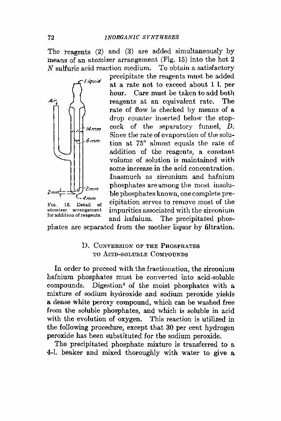
72 INORGANIC SYNTHESES
The reagents (2) and (3) are added simultaneously by means of an atomizer arrangement (Fig. 15) into the hot 2 N sulfuric acid reaction medium. To obtain a satisfactory
FIG. 15. Detail of atomizer arrangement for addition of reagents.
precipitate the reagents must be added at a rate not to exceed about 1 1. per hour. Care must be taken to add both reagents a t an equivalent rate. The rate of flow is checked by means of a drop counter inserted below the stop- cock of the separatory funnel, D. Since the rate of evaporation of the solu- tion a t 75" almost equals the rate of addition of the reagents, a constant volume of solution is maintained with some increase in the acid concentration. Inasmuch as zirconium and hafnium phosphates are among the most insolu- ble phosphates known, one complete pre- cipitation serves to remove most of the impurities associated with the zirconium and hafnium. The precipitated phos-
phates are separated from the mother liquor by filtration.
D. CONVERSION OF THE PHOSPHATES TO ACID-SOLUBLE COMPOUNDS
In order to proceed with the fractionation, the zirconium hafnium phosphates must be converted into acid-soluble compounds. Digestion3 of the moist phosphates with a mixture of sodium hydroxide and sodium peroxide yields a dense white peroxy compound, which can be washed free from the soluble phosphates, and which is soluble in acid with the evolution of oxygen. This reaction is utilized in the following procedure, except that 30 per cent hydrogen peroxide has been substituted for the sodium peroxide.
The precipitated phosphate mixture is transferred to a 4-1. beaker and mixed thoroughly with water to give a

THE EXTRACTION OF H.4F.VIUM A N D ZIRCONIUM 73
homogeneous paste containing about 1.2 mols of the phos- phate (dry basis) per liter of slurry. Adsorbed acid is neutralized (litmus) with sodium hydroxide solution. The slurry is then cooled externally with ice to 10" and the cal- culated amount of 30 per cent hydrogen peroxide (1 l., 30 per cent H202 per mol of ROZ) is added. To this mixture is added, with stirring, a cold concentrated (40 g. per 100 g.) solution of sodium hydroxide (300 g. NaOH per mol of R02). After the mixture has been well stirred, the beaker is transferred to a hot plate, and the temperature of the mixture maintained a t 50 to 70" for 3 hours. At the end of this time the intermediate soluble peroxyzirconate hafnate should be completely decomposed to the insoluble peroxy compounds.* The precipitate is allowed to settle, the supernatant liquor decanted, and replaced with an equal volume of phosphate-free 1 M ammonium sulfate solution. t The supernatant liquors and subsequent washes are filtered on a Buchner funnel using a filter paper suitable for fine precipitates. Washing by decantation is continued until the supernatant liquors no longer give a test for phos- phate.$ The entire precipitate is then transferred to the filter to remove the remainder of the wash liquor.
The precipitate is subsequently transferred to a beaker and dissolved in sufficient 1 : 1 sulfuric acid to give a 2 N sulfuric acid solution containing 2 to 5 per cent ROZ when finally diluted with water. The solution is then boiled to decompose the peroxide. A clear solution results if the precipitate has been washed free of phosphate; if a precipi- tate appears, it is best separated from the mother liquor by centrifugation and re-treated in the prescribed manner. The final solution is analyzed for total oxide and HfOz.
* To test for the completeness of thc digestion, an aliquot of the super- natant liquor is transferrcd to a test tube, and heated to boiling; if no addi- tional precipitate forms the reaction is complete.
t This may be prepared in large quantities from c.p. sulfuric acid and ammonium hydroxide.
3 The ammonium molybdate test is used. Care must be taken that all the reagents are phosphate-frec.

74 I NORCA NIC SYNTHESES
E: FRACTIONATION OF ZIRCONIUM AND HAFNIUM The mechanics of fractionation are the same as for com-
plete precipitation except that an insufficient amount of precipitant is used. To determine what the optimum cut- off value for a given hafnia concentration should be, and to determine also what enrichment may be expected in each
FIO. 16. Comparison of cornpoaition at step N + 1 and step N.
step, the experimental data for this procedure have been treated by the method of Willard.4 The results are expressed in Figs. 16 and 17. Thus, knowing the hafnium content, the mol per cent of ROz to be precipitated is obtained from Fig. 17. The number of grams of phosphoric acid necessary to precipitate this mol per cent of ROz as the phosphate is diluted with 2 N sulfuric acid to give the same volume as that of the 2 to 5 per cent zirconium hafnium oxysulfate which is also in 2 N acid. The two solutions are then added to the hot sulfuric acid solution

T H E EXTRACTION OF HAFNIUM A N D ZIRCONIUM 75
at the same rate. At times it is more convenient to dilute the phosphoric acid to only a fraction of the volume of the zirconium oxysulfate solution to prevent excessive dilution of the phosphoric acid; the rate of addition of the phosphoric acid must then be correspondingly reduced. Care must be taken that the rate of addition of the reagents is such that a constant fraction of the total ROz is removed throughout the precipitation. Since the hafnium concen-
FIQ. 17. and composition of starting material.
Comparison of optimum mol fraction of combined oxides precipitated
trates in the insoluble fraction, the precipitate is filtered, converted to the acid-soluble peroxy compounds, and then dissolved to yield a solution suitable for further fractionation.
By using the prediction curve (Fig. 16) it should be pos- sible, theoretically, to proceed through the fractionation with no analyses other than the initial analysis. However, since actual operating conditions are not as reproducible as would be desired, deviations from the predicted enrich- ment are observed. Since small changes are additive an appreciable error may result within a few steps. It is therefore necessary to determine the hafnium content at frequent intervals.
Starting with a raw material containing 0.1 mol fraction
76 I NORGA NZC SYNTHESES
HfO;, it is possible to obtain, in a series of seven fractions- tions, about a 10 per cent yield of a product with 0.9 mol fraction Hf02. Mother liquors of approximately equiva- lent concentration from the various steps are combined for re-treatment.
F. THE PREPARATION OF LOW-HAFNIUM ZIRCONIA To prepare low-hafnium zirconia, the mother liquor from
the first fractional precipitation is treated with ammonium hydroxide to precipitate the hydroxides, which are then filtered and redissolved in a calculated amount of moder- ately concentrated sulfuric acid. This solution is then diluted with the amount of water required to give a 2 N sulfuric acid solution that contains 5 per cent ROi. From a fraction containing 0.7 per cent hafnium,* one fractiona- tion in which about 60 per cent of the total oxide is precipi- tated as the phosphate will yield a product containing only 0.2 per cent hafnium, Additional fractionations of the mother liquor will reduce the hafnium content to a concen- tration below the sensitivity of the arc spectrographic method used (about 0.05 per cent Hf). Because the impurities concentrate in the most soluble fraction, a com- plete phosphate precipitation is made on the final solution, the precipitate is washed with 2 N sulfuric acid, and then converted to the peroxy compound. For final purification, the acid-soluble peroxy compound is dissolved in hydro- chloric acid, and the oxychloride prepared according to the procedure of Young and Arch.'O The oxychloride may then be used as a starting material for the preparation of any other zirconium compound.
References 1. DEBOER and VAN ARKEL: Z . anorg. allgem. Chem., 141,2848 (1924). 2. COSTER and VON HEVESY: US. patent 1666440 (April 17, 1928); cj.
3. LARSEN, FERNELIUS, and &GILL: Anal. Chem., 16,512 (1943). Chem. Abstracls, 22,2037 (1928).
* Arc spectrographic analyses by Cyrus Feldman, Oak Ridge National Laboratories, Oak Ridge, Tenn.

THE EXTRACTION OF HAFNIUM A N D ZIRCONIUM 77
4. WILLARD and FREUND: Anal. Chem., 18,195 (1946). 5. DEBOER: 2. a m g . allgem. Chem., 166, 1 (1927). 6. Scriumi and PITTMAN: Anal. Chem., 14,312 (1942). 7. MARQUIS, URBAIN, and URBAIN: Compt. rend., 180,1377 (1923). 8. VAN OSDALL: thesis, Ohio State University, 1939. 9. CLMSEN: 2. anal. Chem., 117,252 (1939). 10. YOUNG and Awn: INORGANIC SYNTnEaEs, 2,121 (1946).
CHAPTER V
See also: Ammonium dithiocar- bamate, synthesis 12
Aminoguanidonium hy- drogen carbonate, syn- thesis 11
Hexamminechromium (111) nitrate, synthesis 41
Hexamminenickel(I1) bromide and iodide, synthesis 52
Cyanamide, synthesis 9 Dicyanodiamide, synthesis 10 Barium thiocyanate, synthesis 5 Potassium octacyanomolybdate
(IV) Zhydrate, synthesis 43 Zirconium hafnium phosphates ,
synthesis 19C Tantalum (niobium) (V) fluoride,
synthesis 47E
20. NITROGENT) OXIDE
(Nitrogen Pentoxide, Dinitrogen Pentoxide, Nitric Anhydride)
2HON02 + PzO5+ NzO5 + 2HP03 SUBMITFED BY N. S. GRUENHUT,* M. GOLDFRANK,* M. L. CUSHINC,* AND
G. V. CAESAR* CHECKED BY P. D. CAE5ARt AND c. SHOEMAKERt
Nitrogen(V) oxide appears to have been first prepared in 1840' by passing dry chlorine over dry silver nitrate heated on a water bath, the oxide being collected in solid form in a tube immersed in a freezing mixture. Subsequently, it was prepared by various investigatorsFs through dehydration of concentrated nitric acid by phosphorus(V) oxide. A third method involves oxidation of the equilibrium mix- ture N02-Nz04 with o z ~ n e . ~ * ~ Nitrogen(V) oxide is also reported to form when a mixture of oxygen and nitrogen is passed through an electric arc at high voltage^.^
The method described below represents a modification Stein Hall Research Laboratory, New York, N.Y.
t University of Illinois, Urbana, Ill. 78
Inorganic Syntheses, Volume 111 Edited by Ludwig F. Audrieth
Copyright © 1950 by McGraw-Hill Book Company, Inc.

NZTROGEN(V) OXIDE 79
of the procedure developed by Russ and P ~ k o r n y . ~ It was designed primarily to obtain increased yields of crude nitrogen(V) oxide for nitration experiments.’O The dis- tinguishing feature of the method is an initial freezing of the nitric acid and a slow settling of a thick cover of phos- phorus(V) oxide into the melting acid. In earlier methods, phosphorus(V) oxide was added to the liquid acid.
Procedure The apparatus for the preparation of nitrogen(V) oxide
Oxygen is bubbled into bottle A con- is shown in Fig. 18.
FIO. 18. Apparatus for the preparation of nitrogen(V) oxide.
taining sulfuric acid, through a trap B containing glass wool, into an ozonizer C, thence to a three-necked reaction flask D, receiver E, trap F, and bubble counter G. The appa- ratus is set up in a large hood. Ground-glass connections are advisable throughout, but if these are not available, cork stoppers coated with p a r a 5 may be used.*
If “white nitric acid” is not available, it is advisable to bubble dry oxygen through nitric acid (sp. gr,, about 1.50) for several hours. The acid is then thoroughly chilled in a deep-freeze unit.
* Rubber stoppers and rubber tubing must be eliminated because of attack by ozone. Saran tubing haa been found to be fairly satisfactory, especially in that portion of the apparatus where tubing comes in contact with ozone.

80 INORGANIC SYNTHESES
About 100 g. of the chilled acid is placed in reaction flask D, receiver E is disconnected, and oxygen is bubbled through the acid again for 10 minutes. The acid in D is then frozen solid (important) by immersion of the flask in Dry Ice and alcohol. The passage of oxygen is continued during this operation. Receiver E is also immersed in an alcohol and Dry Ice cooling bath and is connected to the system; oxygen is allowed to pass through for several minutes to remove moist air.
About 125 g. of phosphorus(V) oxide is quickly spread over the surface of the frozen acid in D, the flask stopper sealed tight, the freezing bath of Dry Ice and alcohol removed from under D and replaced with a water bath a t room temperature. The ozonizer is put into operation prior to removal of the freezing bath. As the acid slowly melts, the liquid portion reacts with the large excess of phosphorus(V) oxide. When the initial intense reaction has subsided, the mass is stirred quickly and the reaction allowed to subside again. After the second rush of oxides, the water bath is heated slowly to 40” for several hours until the reaction appears to be substantially complete.
The warm water bath is now removed and ozonized oxy- gen allowed to circulate for an hour or more, depending upon the required degree of purity of nitrogen(V) oxide. The Nz04 content* will also be reduced (1) if ample time is allowed between each of the first two periods of maximum reaction, and (2) by slower and intermittent warming.
A yield of 42 g. is obtained, corresponding to approxi- mately 50 per cent of theory based upon a nitric acid vary- ing between 96 and 100 per cent in concentration. Higher yields may be obtained at the expense of purity.
* An efficient source of ozone is necessary to reduce to a minimum the NlO, content of the product. The checkers employed a “Siemens’ Form Omne’Generator ” purchased from the Central Scientific Company, Chicago, Ill. With slow and careful distillation, it is possible to dispense with the ozonizer C, provided that an NZO, content of 10 to 20 per cent in the sub- limed crystals is not objectionable.10

HYDROXYLAMMONIUM SALTS 81
Properties
Nitrogen(V) oxide is a white, crystalline, unstable solid that sublimes readily just above room temperature.8 It undergoes a first-order decomposition reaction into oxygen and the equilibrium mixture N02-N204. It is readily soluble in cold chloroform (a convenient method of using it) without appreciable reaction and, to a lesser extent, in carbon tetrachloride. Crude nitrogen(V) oxide in chloro- form can be stored for as long as one week a t -20” without excessive decomposition. I t is an extremcly rapid, effi- cient, and safe nitrating agent in chloroform solution, when used in the presence of sodium fluoride as an adsorbent for the nitric acid by-product,’O and offers interesting possi- bilities for continuous processes of nitration.
References
1. DEVILLE: Compt. rend., 26, 257, 1449 (1840). 2. WEBER: Pogg. Ann., 147, 113 (1872). 3. BERTHELOT: Bull. soc. chim., 21, 53 (1874). 4. Rr:ss and I’OKORNY: Monatsh., 34, 1051 (1913). 5. DANIELS and BRIGHT: J . Am. Chem. Sac., 42, 1131 (1920). 6. RERL and SAESGER: dfonutsh., 63-64, 1036 (1029). 7. HELBIG: Alli accud. Lincei, I111 11, 311 (1902). 8. YOST and RUSSELL: “Systematic Inorganic Chemistry,” Prentice-Hall,
9. EHRLJCH and Russ: Afonalsh., 92,917 (1911). Inc., New York, 1944.
10. CAESAR and GOLDFRANK: J . Am. Chem. Soc., 88,372 (1946).
21. HYDROXYLAMMONIUM SALTS SGsMIlTED BY h i I L J P F. TRYON* CHECKED B Y w. v. FACKLER, J R . , t AND L. F. AUDRIETH~
Hydroxylammonium salts are reagents usually employed as sources of hydroxylamine for various inorganic and organic reactions. The chloride and sulfate are the better known commercially available salts obtained by the hydrol- ysis of the nitroparaffins. The arsenate,
* Commercial Solvents Corporation, Terre Haute, Ind. t University of Illinois, Urbana, Ill.
a2 INORGANIC SYNTHESES
and oxalate1v6 represent three sparingly soluble salts that can be obtained from the chloride or the sulfate by meta- thesis with the corresponding sodium salts.
Procedure
A. HYDROXYLAMMONIUM PHOSPHATE
3(NH,OH)Cl+ H3P04 + 3NaOH + (NH,0H)aP04 + 3NaC1+ 3H20
A mixture of 210 g. (3 mols) of hydroxylammonium chlo- ride and 200 ml. of water is warmed to about 40" to dissolve the salt. The solution is filtered to remove any sediment, if necessary, and transferred to a 1500-ml. beaker. A mechanical stirrer and a thermometer are introduced into the solution. An empty cooling bath is placed around the beaker. The stirrer is placed in operation and stirring is continued throughout the synthesis of the compound. One hundred fifteen grams of 85 per cent phosphoric acid (1 mol) is next added rapidly.* A cooled solution of 120 g. of sodium hydroxide (3 mols) in 400 ml. of water is then added from a dropping funnel at a rapid dropwise rate.t The hydroxylammonium phosphate usually starts to crystallize toward the end of the addition. When all of the sodium hydroxide solution has been added, the crystal slurry is cooled to 15' by use of the cooling bath. The crystals are separated from the mother liquor by filtration through a 350-ml. sintered-glass funnel, and washed with three 100-ml. portions of water. Purification by washing is best accomplished by breaking the vacuum, and stirring the crystals in the funnel with each separate portion of wash water. If high purity is not necessary, the wet crystals are dried in air overnight, and then in uacuo over phos-
* Occasionally, some of the hydroxylammonium chloride will. crystallize at this point, but it all redissolves during the next step.
t The temperature of the solution will generally rise no higher than 70" toward the end of thia addition. If it ehould go above 75", ice and water are placed in the cooling bath in order to prevent the possible gaseous decomposition of the hydroxylamine salt.

HYDROXYLAMMONIUM SALTS 83
phorus(V) oxide. Approximately 175 to 180 g. of a crude product with a purity of about 95 per cent is readily obtainable.
Purification can be effected by dissolving the wet crystals (total yield of crude product) in 1750 ml. of water at 80 to 85", cooling to about 15" to effect crystallization, followed by filtration and washing. The recrystallized compound is dried as recommended above. About 140 to 145 g. (72 per cent) of a product with a purity of 98 per cent is obtainable in this manner.
B. HYDROXYLAMMONIIJM ARSENATE
3(NH30H)Cl + NazHAsOa.7Hz0 + NaOH 3 (NH30H)3AsOr + 3NaC1+ 8H20
The conditions for preparation of the arsenate are similar to those specified for the phosphate, except that a solution of 312 g. (1 mol) of disodium hydrogen arsenate 7-hydrate in 300 ml. of water (heated to 50" to effect solution) is sub- stituted for the phosphoric acid. Hydroxylammonium arsenate may begin to crystallize before all of the arsenate has been added. An uncooled solution of 40 g. of sodium hydroxide (1 mol) in 100 ml. of water is added to effect neutralization. Three 150-ml. portions of water are used to wash the crude product. The yield is 200 to 210 g. of a product whose purity is approximately 95 per cent based on the hydroxylamine content. Purification can be effected by recrystallization of the arsenate from eight times its weight of water. Recovery amounts to about 145 g. (approximately 60 per cent) of a product with a purity of 98 per cent or better.
C. HYDROXYLAMMONIUM OXALATE
2(NH30H)C1 + H2C204-2Hz0 + 2NaOH + (NHaOH)2C201 + 2NaC1+ 4H20
The method for preparation of the oxalate is similar in principle to that used for the corresponding phosphate, the
a4 INORGANIC S Y N THESES
solution of hydroxylammonium chloride being somewhat more dilute [140 g. (2 mols) in 400 ml. of water]. While this solution is being stirred mechanically, 126 g. of crystal- line oxalic acid 2-hydrate (1 mol) is added all at once. The crystals of acid do not all dissolve. After a few minutes, a solution of 80 g. of sodium hydroxide (2 mols) in 200 ml. of water is added at a rapid dropwise rate. A considerable amount of the hydroxylammonium oxalate will crystallize during this addition. The hot slurry is stirred for about 30 minutes, and is then cooled to about 15" and filtered. The crystals are washed with three 100-ml. portions of water. The crude product, weighing about 130 g., will generally contain about 10 per cent oxalic acid. It can be purified by recrystallization from about eight times its weight of water with an average yield of 95 g. (60 per cent) of a product whose purity by analysis will be better than 99 per cent.
Analysis
Analysis for the hydroxylamine content is effected by the Raschig method. The recommended procedifie is a modi- fication of the method given by Scott.G Approximately 0.1 g. of sample is dissolved in 75 ml. of water in an Erlen- meyer flask and 30 ml. of a saturated solution of iron(II1) ammonium sulfate is added, followed by 10 ml. of 50 per cent sulfuric acid. The solution is boiled for 10 minutes, treated with approximately 5 to 10 ml. of phosphoric acid to reduce the color, then diluted with 200 ml. of water and titrated immediately with standard permanganate solution.
Properties
The normal hydroxylammonium salts of phosphoric, arsenic, and oxalic acids are colorless crystalline com- pounds. They are insoluble in organic solvents, and only sparingly soluble in water a t room temperature. Some solubility values from the literature are given below. The solubility of the arsenate and the decomposition points of the three salts were determined on the recrystallized mate-

THE POLY- A N D METAPHOSPHATES 85
rial prepared in accordance with directions given in this synthesis.
Property
~~~ ~~
Hydroxylammonium salt
Phosphate 1 Arsenate 1 Oxalate
Solubility, g. per 100 ml. of water: 20" . . . . . . . . . . . . . . . . . . . . . . . . . . . . . 40" . . . . . . . . . . . . . . . . . . . . . . . . . . . . . 60" . . . . . . . . . . . . . . . . . . . . . . . . . . . . . 80" . . . . . . . . . . . . . . . . . . . . . . . . . . . . .
Decomposition point, approx . . . . . . . . .
1 . 9 (3) 4 . 2 8 . 4
15.3 165"
2 . 4
136"
1 .4 (5)
180" I
Hydroxylammonium phosphate serves as a convenient reagent for the preparation of oximes; the saturated aque- ous soIution has a pH of about 5, the pH of maximum rate of oxime formation.
References
1. LOSSEN: Ann. Suppl., 6, 230 (1868). 2. UHLENHUTH: Ann., 311, 117 (1900). 3. ADAMS: Am. Chem. J. , 28, 198 (1902). 4. KOHLSCH~STCER and HOFMANN: Ann., 307,314 (1899). 6. SIMON: Bull. soc. chim. (3) 33, 412 (lm5). 6. Scorn: "Standard Methods of Chemical Analysis," 5th ed., Vol. 1, p. 647,
D. Van Nostrand Company, Inc., Sew York, 1939.
22. THE POLY- AND METAPHOSPHATES AND THE STRONG PHOSPHORIC ACIDS
BY L. F. AVDRIETH* AND R. N. BELL?
The sodium phosphates, polyphosphates, and metaphos- phates, the preparation of which is described in this volume (see syntheses 24 to 26), represent a diversified group of compounds ; their relationships are most easily elucidated by a consideration of their structures. The structural unit that characterizes all phosphates is the PO, tetrahedron, the phosphorus atom being surrounded tetra-
* University of Illinois, Urbana, Ill. t Victor Chemical Works Research Laboratory, Chicago Heights, Ill.
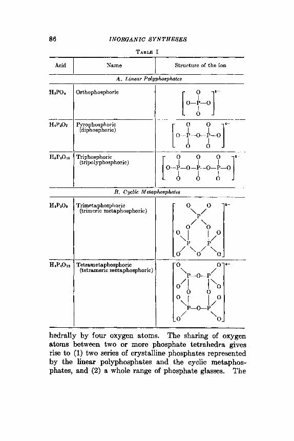
86 INORUANIC S Y N T H E S E S
TABLE I
Acid I I
Name . Structure of the ion
A . Linear Polyphosphates
Orthophosphoric
Pyro hosphoric (dipiosphoric)
Triphosphoric (tripolyphosphoric)
R. Cyclic Metaphosphtes
rrimetaphosphoric (trimeric metsphosphoric)
Tetrametaphosphoric (tetrameric metaphosphoric)
[ o-i-o]
8 -
/ O -0 \ o/r-o-y\o \A I /O
0 0
-0-P
0
/ \
Lo' 'ol
hedrally by four oxygen atoms. The sharing of oxygen atoms between two or more phosphate tetrahedra gives rise to (1) two series of crystalline phosphates represented by the linear polyphosphates and the cyclic metaphos- phates, and (2) a whole range of phosphate glasses. The

THE POLY- A N D METAPHOSPHATES 87
known crystalline poly- and metaphosphates are listed in Table I, together with the structures of the respective ions or groups.
Conversion of orthophosphates into poly- and metaphosphates (and into the phosphate glasses) is accomplished in all known cases by high-temperature reac- tions. Conversion reactions leading to these products may be regarded as examples of polyanionic aggregation (com- monly called "molecular dehydration "). These reactions are not unlike similar ones in which increase in the hydro- gen-ion concentration of solutions of chromates (also molyhdates, tungstates, and vanadates) causes their con- version successively into di-, tri-, and tetrachromates. 2*3 There is one significant difference, however, in that the polyanionic aggregation of the phosphates does not take place in aqueous solution, but only at higher temperatures either in the solid state or upon fusion. Equations that are usually employed to represent these reactions are given in Table 11. Since these do not reveal the true nature of the reactions as acid-base phenomena, they have been rewritten in parentheses as involving reactions between the hydrogen ion and the phosphate ion. It is evident that the extent of polymerization is definitely a function of acidity, that is, of the ratio of hydrogen ion to phosphate ion.
Preparation.
TABLE 11. PFUZPAR4TION OF POLY- AND METAPHOSPHATEB
Ratio H+/PO,S- 1. 2HP04'-, P1OI4- + HtO 1 .oo
1.33
2 .oo
(2H+ + 2P04*- + P20T4- + HzO) 2. HPPOI- + 2HPO4'-t PaOio6- + 2H20
(4HC + 3P04s-+ PaOioS- + 2H2O) 3. x H z P 0 1 - 4 xHZO + x(POa)-*
(2H+ + POI'- -+ POa- + HzO) *Where x(P0i)- - (P,Oo):-, (P401n)J-, polymetaphoaphate g l m and other possible
metaphoephates.
Thus, fusion or heating of a monohydrogen phosphate will cause aggregation to proceed only as far as the pyro- phosphate stage (synthesis 24) while triphosphate (synthe- sis 25) is obtainable in a more acidic medium, such as is

88 INORGANIC SYNTHESES
furnished by a 2: 1 molar mixture of mono- and dihydrogen phosphate. In a still more acidic medium, as in the case of dihydrogen phosphate, heating leads to formation of various metaphosphates. The trimetaphosphate (synthe- sis 26A) is obtained at moderate temperatures (400 to 500°), whereas the polymetaphosphate glass (synthesis 26B) is produced by heating to fusion at still higher temperatures (above 620”).
Fusion of any sodium phosphate with a NazO : P20s ratio varying from 1 : 1 to 5 : 3, followed by rapid chilling, results in the formation of the so-called “phosphate glasses.” Such products dissolve in water to give solutions of poly- anionic aggregates with ionic weights ranging up to the equivalent of 500 POs units, and possibly even higher. The best known example of this class of materials is Gra- ham’s salt. It has commonly been called “hexametaphos- phate.” Recent investigations have shown that there is absolutely no justification for this name. It is even doubtful that any discrete unit consisting of 6 PO, groups is present in such a product. Various physical methods have been used to show that solutions of phosphate glasses contain aggregates of high ionic weight. Fractionation may be accomplished by the portionwise addition of an organic solvent such as acetone to an aqueous ~o lu t ion .~ The first few fractions, containing the least soluble com- ponents, are found to have extremely high ionic weights. As more and more of the organic solvent is added to the residual solution, fractions are precipitated with smaller and smaller ionic weights. Average ionic weights of poly- metaphosphates in such solutions vary from 10,000 to 25,000.
The greater the state of aggregation (condensation polymerization), the more acidic are the poly- and meta- phosphates.s Reference should again be made in this particular instance to the analogous behavior of the poly- chromates. Addition of a base to solutions of the poly- chromates causes their degradation to simpler- aggregates,
THE POLY- AND METAPHOSPHATES 89
eventually to the chromate ion itself. This analogy may be carried over to the phosphate system; the polymeta- phosphate glasses may be looked upon as anionic acids. Anionic bases will effect depolymerization to ortho- and pyrophosphates. Fused Graham’s salt has long been used in analytical chemistry in the well-known “phosphate bead test ” for the qualitative detection of various metallic oxides. These dissolve in the metaphosphate glass to form varicolored metallic ortho- and pyrophosphates.**O Fusion of sodium sulfide with sodium polymetaphosphate is claimed to afford a convenient method for the preparation of the monothioorthophosphate.’O Fusion of equimolecular weights of sodium fluoride with sodium polymetaphos- phate results in formation of sodium monofluophosphate (synthesis 27).
Hydrolysis. All of the polyphosphates and metaphos- phates undergo reaction with water. Such reactions have commonly been termed “reversion” reactions, and, if carried out under appropriate conditions, will cause depoly- merization of poly- and metaphosphates to simple ortho- phosphate ions. In these reactions, water appears to act as a base with respect to the higher poly- and metaphos- phates. A summary of the principal hydrolytic or rever- sion reactions of the various poly- and metaphosphates is presented in Table 111.”
The Phosphoric Acids. Only two of the simple phos- phoric acids have been prepared in the crystalline state, namely, orthophosphoric acid12 and pyrophosphoric acid (synthesis 23). Several of the others have been prepared in dilute aqueous solution by treatment of the sodium salts with exchange resins containing replaceable hydrogen, or by treatment of the appropriate metallic salt with hydrogen sulfide.
It is significant, however, that the so-called “strong” phosphoric acids, those having a phosphorus(V) oxide con- tent higher than 72.4 per cent [which corresponds to the phosphorus(V) oxide content of orthophosphoric acid], are

90 INORUANIC SYNTHESES
Trimetaphosphate
Triphosphate
mixtures of poly- and metaphosphoric acids, the composi- tions being functions of the phosphorus(V) oxide content. These strong phosphoric acids may be obtained by (1) high-temperature dehydration of &thophosphoric acid, (2) careful hydration of phosphorus(V) oxide, and (3) treat- ment of 85 per cent orthophosphoric acid with phos- phorus(V) oxide and subsequent heating.
(NaPOd8 + HzO --t NaaHaPaOlo NaaHpP8O~o + 2Ha0 + 3NaH2P04
Na6P3OI0 + HzO -+ NasHPzOr + Na2HP04
TABLE 111. HYDROLYSIS REACTIONS
In Water
“Hexametaphosphate” I 3(NaPOa)s + 12HzO + 2(NaPOa)a + 12NaHzPO4
Pyrophosphates
In 1 per cent NaOH Solution
Figure 19 depicts the compositions of the strong phos- phoric acids.I3 A strong phosphoric acid containing 82 per cent phosphorus(V) oxide is a mixture consisting of ortho-, pyro-, tri-, and “ hexameta-” phosphoric acids, and in addition a not unappreciable percentage of some yet- to-be-identified constituent. The compositions of the various strong phosphoric acids were determined by neu- tralization of the products with cold aqueous solutions of sodium hydroxide followed by analyses using the methods that are outlined below.
It is quite apparent that the strong phosphoric acids are not to be regarded as mixtures of orthophosphoric acid containing exceme8 of phosphorus(V) oxide. In this

THE POLY- AND METAPHOSPHATES 91
respect, the strong phosphoric acids differ markedly from “ oleurn” or fuming sulfuric acid which can be represented 8s containing an excess. of sulfur trioxide. This difference appears to have been overlooked by a great many investi- gators who have concerned themselves with the phos- phorylation of organic compounds.
Fro. 19. Composition of strong phosphoric aaids.
Method of Analysis for Mixtures of Soluble Phosphates. Quantitative estimation of the compounds of simple mix- tures of phosphates, polyphosphates, and polymetaphos- phates can be effected without too much difficulty. Deter- minations of orthophosphate, pyrophosphate, triphosphate, and so-called “ hexametaphosphate” are usually made on mixtures of soluble phosphates. Total phosphorus content is also determined by hydrolyzing all other phosphates to orthophosphoric acid. No distinctive analytical meth- ods are, however, available for the direct quantitative determination of the cyclic metaphosphates.
1. Preparation of the Sample. A stock solution of the sample is made by dissolving 2.5 g. in distilled water at

92 INORGANIC SYNTHESES
room temperature and diluting to a volume of 250 ml. Aliquots of suitable sizes are taken from this solution for the determination of the phosphates. When heterogeneous mixtures are to be analyzed, it may be necessary to weigh out a larger sample and to dilute proportionately.
2. Reagents. a. O~thophosphate.~~ Two reagent solu- tions must be prepared beforehand in addition to a standard solution that contains a known quantity of orthophosphate.
Solution 1. Eighteen and seventy-five hundredths (18.75) grams of c.p. ammonium molybdate is dissolved in 300 ml. of distilled water, and 150 ml. of concentrated sulfuric acid is added. The solution is cooled and diluted to 500 ml.
Three and one-half (3.5) grams of anhydrous sodium sulfite is dissolved in 50 ml. of distilled water. To this solution is added 0.75 g. of l-amino-2-naphthol4sul- fonic acid. Another solution is prepared containing 45 g. of sodium hydrogen sulfite in 400 ml. of distilled water. The sulfite-naphthol-sulfonic acid solution is added to the latter and the mixture diluted to 500 ml.
Standard Phosphate Solution. Potassium &hydrogen phosphate iLrecrystallized and dried at 85". A quantity of exactly 0.3472 g. of this substance is dissolved in distilled water, and the solution is diluted to 250 ml. Twenty-five milliliters of this stock solution, when diluted to 250 ml., constitutes a standard solution, 1 ml. of which equals 0.1 mg. of HBP04.
The following solutions are required: (1) sodium hydroxide solution, 0.1 N ; (2) hydro- chloric acid solution, 0.2 N ; (3) zinc sulfate solution, 12.5 per cent solution of ZnSO4.7H20 adjusted to pH 3.8.
c. Polymetaphosphate (Hexametaphosphate). Two solu- tions are required: (1) hydrochloric acid solution, 1.0 N ; (2) barium chloride solution, 10 per cent solution.
3. APParatus. In order to carry out the analyses out- lined in detail below, it is necessary to have available a photoelectric colorimeter and a glass electrode pH meter and titration assembly.
Solution 2.
b. Pyro- and Triphosphates.
T H E POLY- A N D METAPHOSPHATES 93
Procedure
An aliquot of the stock sample solu- tion is taken that does not contain more than 0.4 mg. of phosphate. It will usually be necessary to withdraw a 10-ml. sample of the solution and dilute to 100 ml. One milliliter of the latter represents an aliquot that will contain in the neighborhood of 1.0 mg.* The aliquot is placed in a 25-ml. graduated cylinder and diluted to approximately 15 ml. Half-milliliter portions each of reagents (1) and (2) are next added. The sample is diluted to 25 ml. and mixed thoroughly. After it has stood for 10 minutes at room temperature (25 to 30") the intensity of the blue color is measured on a photoelectric colorimeter. A blank should be run on the reagents and this figure should be used in adjusting the zero point on the colorimeter. The ortho- phosphate content is read from curves prepared from standard orthophosphate solutions. A red filter (Corning No. 244) increases the sensitivity of the determinati0n.t
Pyro- and Triphosphates.16 A 50-ml. aliquot (0.5 g . ) of the sample is adjusted to pH 3.8 and diluted to 100 ml. (+2.0 ml.). The pH of this solution is readjusted after dilution if necessary. Seventy milliliters of the zinc sulfate reagent is added and the solution titrated back to pH 3.8 with 0.1 N sodium hydroxide.$ Any pyrophos- phate that may be present in the sample will have been precipitated as zinc pyrophosphate. After settling, the precipitate is filtered, washed lightly, and then purified in the following manner: The precipitate is dissolved in 15 to
0rthopho~phate.l~
* If the sample is too high in orthophosphate, a smaller aliquot must be
t The color developed by this method is not sufficient for accurate visual If visual methods are used, the mcthod of Bell and Doisyl5
4 . \ t l t l i t i o i i to zinc sulfate results in the precipitation of zinc pyrophosphate and tlit, formation of a complex sodium zinc triphosphate. Formation of both of tli(w substances is accompanied by liberation of hydrogen ions. 'iYBrstion wit 11 sodium hydroxide, thrrefore, effects neutralization of sulfuric a~idVbrratci1 hy both pyrophosphate and triphosphate.
taken.
c o i ~ ~ ~ x i r i w n . shorlld I W L'ollowed.

94 INORGANIC SYNTHESES
20 ml. of 0.2 N hydrochloric acid and the solution diluted to 150 to 200 ml. volume; 25 ml. of zinc sulfate reagent is added and the pH is brought back to 3.8 with 0.1 N sodium hydroxide. The precipitate is allowed to settle and is filtered and washed with distilled water at room tempera- ture. The precipitate is ignited, first at 400 to 500" and then at 700 to 800", and weighed as ZnzPz07. The pyro- phosphate content of the sample is calculated from the weight of zinc pyrophosphate ;' the triphosphate content is calculated from the titration after correction has been made for the titration equivalent of the pyrophosphate. The following factors are employed:
g. ZntPz07 X 0.572 = g. P107 X 0.584 p g. Hip207 X 0.872 = g. Na4Pz0, X 65.5 = ml. 0.1 N NaOH due to pyrophosphate
Balance of titration: ml. of 0.1 N NaOH x 0.0177 = g. PI0to
X 0.0181 g. HsPsOio x 0.0258 = g. Na~P~Olo
The factors shown above for triphosphate are empirical factors applicable only when the concentration of zinc sulfate in the titrated solution is as recommended. Polymetaphosphate (Hexametaph~sphate).~' A 10-ml.
aliquot (0.1 g.) of the sample solution diluted to 50 ml. is acidified to methyl orange with 1.0 N hydrochloric acid, and 0.5 ml. excess is added. Barium polymetaphosphate is precipitated by slowly adding 15 ml. of 10 per cent barium chloride reagent while stirring. When the precipitate has settled, it is filtered off and washed with 0.1 per cent barium chloride solution. The precipitate is dissolved in 20 to 30 ml. of 50 per cent nitric acid and hydrolyzed by boiling for 20 to 30 minutes. The resulting orthophosphate .is precipitated as ammonium phosphomolybdate ; the phos- phorus content of the latter is determined as outlined in the following paragraph for total phosphorus, and Calculated as polymetaphosphate.

THE POLY- A N D METAPHOSPHATES 95
Total phosphorus (as PzOa). A 10-ml. aliquot is diluted to approximately 100 ml., and 20 ml. of concentrated nitric acid is added. The solution is boiled for 20 to 30 minutes to hydrolyze the p l y - and metaphosphates to orthophos- phate. After cooling, the solution is neutralized to methyl orange with ammonium hydroxide and is again cooled to room temperature. Phosphate is precipitated as ammo- nium 12-molybdophosphate, filtered, washed, and titrated by the voIumetric procedure recommended for fertilizers. 18*
References
1. A U D R ~ T H and HILL: J. Chem. Education, 26, 80 (1948). 2. HILL: thesis, University of Illinois, 1948. 3. AUDRIETH and MOELLER: J. Chem. h’ducution, 20,219 (1943). 4. VAN WAZER: private communication. 5. KARBE and JANDER: Kolloid-Beihefte, 64, 1 (1942). 6. MALGREN and LAMM: 2. anotg. allgem. Chem., 246, 103 (1940); 262,
7. WEINBERG: thesis, University of Illinois, 1947. 8. WALBROTH: Bull. SOC. chim., (2) 39, 316 (1883). 9. COHN: Chem. News, 129, 32 (1934).
256 (1944).
10. ZINTL and BERTRAM: 2. amrg. allgem. Chem., 246, 16 (1940). 11. BELL: Ind. Eng. Chem., 39, 136 (1947). 12. WEBER and KING: INORGANIC SYNTHESIS, 1, 101 (1939). 13. BELL: I d . Eng. Chem., 40, 1464 (1948). 14. FISKE and SUBBAROW: J. Biol. Chem., 66,375 (1925). 15. BELL and DOISY: ibid., 44, 55 (1920). 16. BELL: A d . Chem., 19, 97 (1947). 17. JONES: Anal. Chem., 14, 536 (1942). 18. “Methods of Analysis of Official Association of Agricultural Chemists,”
6th ed. pp. 22-3, George Banta Publishing Company (The Collegiate Press), Menasha, Wis., 1945.
* No satisfactory method has yet been worked out for the direct deter- mination of trimetaphosphate. The difference between (1) the total water- soluble Pa05 content and (2) the sum of that calculated for each of the phosphates is usually ascribed to the trimetaphosphate content and calcu- lated as such. If this amounts to an appreciable percentage, its presence can be verified by adding 1 g. of sodium hydroxide to a 50-ml. aliquot of the sample solution, boiling for 5 minutes, and redetermining the tri- phosphate content. When treated in this manner, trimetaphosphate is converted to triphosphate in accordance with the following -equation: (NaPOI)* + 2XaOH + NasPIOlo + H20. Any incream in the triphos- phate content is calculated to trimetaphosphate. Although this is not an exact procedure, it does verify the presence of trimetaphosphate and gives an estimate of the amount present.

96 INORGANIC SYNTHESES
23. PYROPHOSPHORIC ACID
(Diphosphoric Acid) SUBWITED BY J. E. MALOWAN’ CHECKED BY R. N.
Solid pyrophosphoric acid is obtainable only by the spontaneous crystallization of a polyphosphoric acid mix- ture containing 79.8 f 0.2 per cent phosphorus(V) oxide. Such a liquid polyphosphoric acid may be prepared (1) by dehydration of 85 per cent orthophosphoric acid, (2) by dissolving phosphorus(V) oxide in 85 per cent orthophos- phoric acid, (3) by adding water to commercial “tetraphos- phoric acid,” or (4) by allowing phosphorus(V) oxychloride to react with 85 per cent phosphoric acid. The first three of these procedures are preferred.
Procedure
A liquid polyphosphoric acid containing approximately 80 per cent phosphorus(V) oxide is first prepared by one of the methods described below. After analysis, its composi- tion is adjusted by addition of water to give a product containing 79.8 per cent phosphorus(V) oxide [theoretical for pyrophosphoric acid, 79.76 per cent phosphorus(V) oxide].
A. CONCENTRATION OF
85 PER CENT ORTHOPHOSPHORIC ACID
The commercially available 85 per cent orthophosphoric acid is concentrated by heating in an oil bath (or by using a Glas-col heater) to prevent local overheating and under vacuum to reduce the required temperature. Concentra- tion is continued until loss in weight amounts to 25 to 30 g. per 100 g. of 85 per cent orthophosphoric acid (theory 22.81 per cent). It will generally be necessary to continue
Monsanto Chemical Company, Central Research Dept., Dayton, Ohio. t Victor Chemical Works Research Laboratory, Chicago Heights, 111.
Inorganic Syntheses, Volume 111 Edited by Ludwig F. Audrieth
Copyright © 1950 by McGraw-Hill Book Company, Inc.

P YROPHOSPHORIC ACID 97
heating until the temperature of the liquid acid has reached approximately 180".
B. SOLUTION OF PHOSPHORUS(V) OXIDE IN
85 PER CENT ORTHOPHOSPIIORIC ACID
The required quantity of phosphorus(V) oxide is added slowly and in small portions (3 to 5 g. at a time) to the acid in a two-necked, round-bottomed flask equipped with a motordriven stirrer. The solution of the oxide proceeds slowly, and vigorous agitation together with application of heat is required to obtain a clear solution. Approximately 95 to 100 g. of phosphorus(V) oxide should be added for each 100 g. of 85 per cent orthophosphoric acid.
C. DILUTION OF TETRAPHOSPIIORIC ACID Commercial tetraphosphoric acid contains about 82.5
per cent phosphorus(V) oxide (theory, 84 per cent). Three grams of water or 12 g. of 85 per cent orthophosphoric acid should be added for each 100-g. portion of the acid. The water or acid is added slowly with agitation. Stirring will be difficult at fist because of the very high viscosity of the starting material, but the heat of dilution will serve to decrease the viscosity rapidly.
The total phosphorus(V) oxide content of the product, prepared by one of the above procedures, is then deter- mined4 (synthesis 22) and the composition adjusted to 79.76 per cent phosphorus(V) oxide by the addition of water. The acid is allowed to crystallize spontaneously. If the solution is permitted to stand at room temperature, i t may be two weeks or longer before solidification is complete. If the solution is kept in an ice chest, crystallization will usually occur within a few days to form a hard cake containing 85 to 95 per cent pyrophosphoric acidSv6 together with occluded mother liquor consisting largely of a mixture of ortho-, meta- and triphosphoric acids. During crystallization a slight increase in volume takes place and may result in the rupture of the glass container. It is

98 INORGANIC SYNTHESES
therefore advisable to use a comparatively large bottle or a stainless-steel or lead vessel. The product is very hygro- scopic and must be stored in a closed container.
Properties Pure pyrophosphoric acid exists in the solid form, or
dissolved in various inert solvents. When heated above its melting point (61”), it decomposes into a liquid mixture consisting of ortho-, pyro-, tri-, and polymetaphosphoric acids.*S2 The crystalline acid may be dissolved in ice water to give a solution that will remain unchanged for some time. When the compound is dissolved in water at higher temperatures, hydra tion occurs to give increasing amounts of orthophosphoric acid. Molecular-weight deter- minations indicate that pyrophosphoric acid exhibits some tendency to form polymeric aggregates of compositions up to (H4P20,),. Solution in glacial acetic acid or in water appears to effect slow depolymerization.3
References
1. LUM, MALOWAN, and DURQIN: Chem. &. Met. Eng., 44,721 (1937). 2. BELL, Znd. Eng. Chem., 39, 136 (1947). 3. HOLT and MYERS: J. Chem. SOC., 99, 384 (1911). 4. “Methods of Analysis of the Association of Official Agricultural Chem-
ists,” 6th ed., p. 22, George Banta Publishing Company (The Collegiate Press), Menasha, Wis., 1945.
5. BRITSKE and DRAQUNOW: J . Chem. Z n d . (U.S.S.R.), 4,49 (1927). 6. BELL: Anal. Chem., 19, 97 (1947).
24. SODIUM PYROPHOSPHATES
(Sodium Diphosphates)
SUBMITTED BY R. N. BELL” CHECKED BY w. L. JoLLrt AND L. F. AuDmwmt
The sodium pyrophosphates are the first products formed in the dehydration (aggregation) of the sodium orthophos- phates. Careful thermal treatment of sodium dihydrogen
* Victor Chemical Works Research Laboratory, Chicago Heights, III. t University of Illinois, Urbana, Ill.

SODIUM PYROPHOSPHATES 99
orthophosphate leads to the dihydrogen pyrophosphate as an intermediate. Complete thermal dehydration of diso- dium hydrogen orthophosphate yields the tetrasodium pyrophosphate. An alternative method of preparing the dihydrogen pyrophosphate by crystallization from strong acetic acid solution is also presented.
Procedure
A. DISODIUM DIHYDROGEN PYROPHOSPHATE
2NaH2POa 5 Na2H2P207 + H20 Na4P207 + 2HCtHs02 3 Na2H2P207 + 2NaC2H302
Pure sodium dihydrogen orthophosphate, NaH2P04, when heated to 210" for 12 hours, gives a product that will analyze over 97 per cent as Na2H2P207 by the methods of Britske and Dragunov' or of Bell.2 Recrystallization of the orthophosphate and drying at 70" before converting to the pyrophosphate is recommended. When prepared in this manner the crystals are too small for optical measure- ments. Larger crystals are produced by the following alternative method.
To 100 ml. of a saturated aqueous solution of tetrasodium pyrophosphate at 40" there is added 75 ml. of glacial acetic acid. After the acetic acid has been added, the tempera- ture is brought back up to 40" and the solution agitated until crystallization is complete (approx. 2 to 3 hours). Crystals will appear in 30 to 60 minutes and grow slowly. When crystallization has proceeded for about 30 minutes, the temperature may be dropped slowly to 30", but not less.* The crystals are filtered off using vacuum, washed with two portions of ice water, and dried at 100". This procedure yields about 5 g. of anhydrous crystals which, if grown slowly enough, are of sufficient size for study under a microscope.
* At lower temperatures, a mixture of anhydrous and hydrated crystals, NazH~Pfi,.6Hp0, is obtained. Below 20°, the hydrate predominates.

100 INORGANIC SYNTHESES
B. TETRASODIUM PYROPHOSPHAI'E
2NazHP04+ Na4P207 + HzO
Tetrasodium pyrophosphate is formed when pure diso- dium hydrogen orthophosphate is heated to 500" for 5 hours. The product will contain better than 98 per cent Na4P207. Crystalline masses large enough for optical measurements are produced by heating in platinum to above the melting point of the tetrasodium pyrophosphate, 800", and cooling slowly. Higher temperatures or longer heating times do not change the tetrasodium pyrophos- phate, as this is the final product in the dehydration of disodium hydrogen orthophosphate.
Properties
Disodium dihydrogen pyrophosphate dissolves slowly in cold water, a 1 per cent solution having a pH of 4.1 to 4.3. One hydrate, NazH2P2O7.6Hz0, can be crystallized from aqueous solutions at slightly below room temperature. The hydrated crystals are biaxial negative with a = 1.456, /3 = 1.464, and y = 1.465(+.002). When heated they lose their water of crystallization around 36". In aqueous solution the disodium pyrophosphate hydrolyzes to ortho- phosphate, the rate of hydrolysis depending on the tem- perature. At 70" a 1 per cent solution is hydrolyzed approximately 10 per cent in 6 hours; a t 100" the hydrolysis is complete in less than 6 hours.3
When anhydrous disodium dihydrogen pyrophosphate is prepared by the acetic acid method, the product is sufficiently crystalline for optical measurements. The crystals are orthorhombic pyramids, biaxial negative with a = 1.501 k .002,p = 1.514 k .005, andy = 1.522 k .002. Ingerson and Morey4 give a' = 1.510 and y' = 1.517 for very fine needle crystals.
Tetrasodium pyrophosphate is quite soluble in cold water ; a 1 per cent solution has a pH of 10.2. It hydrolyzes to orthophosphate in aqueous solution but the rate of
SODIUM TRIPHOSPHATE 101
hydrolysis is much slower than for the more acid pyrophos- phate. No noticeable hydrolysis takes place in 60 hours at 70°.a One hydrate is known, Na4P20,-10H20, that can be crystallized from aqueous solution below 79". The hydrate melts at 79.5" but is efflorescent at temperatures slightly below the melting point. A fairly accurate melting-point determination can be made with the hot-stage microscope by mounting the crystals in an inert liquid such as mineral oil. The hydrated crystals are biaxial positive with a = 1.450, /3 = 1.453, and y = 1.460 ( f .002). Anhy- drous tetrasodium pyrophosphate is biaxial positive with a = 1.475, /3 = 1.477, and y = 1.496 ( k .002).
References
1. BRITSKE and DRAGUNOV: J . Chem. Ind. (U.S.S.R.), 4,49 (1927). 2. BELL: Anal. Chem., 19, 97 (1947). 3. BELL: I d . Eng. Chem., 39, 136 (1947). 4. INGERSON and MOREY: Am. Mineral., 28,448 (1943).
26. SODIUM TRIPHOSPHATE
(Sodium Tripolyphosphate)
2NaZHP04 + NaH2P04 3 Na5P3010 + 2Hz0
SUBMITTED BY R. N. BELL* CHECKED BY W. L. J o L L Y t AND L. F. AUDRIETA~
Sodium triphosphate (more frequently called tripolyphos- phate), Na6P3Ol0, occurs in two forms, which are usually designated as types I and 11. By varying the technique of heating, either type can be made from a mixture consist- ing of (1) 2 mols of a sodium phosphate having a sodium- to-phosphorus ratio of 2:1, and (2) 1 mol of a phosphate having a 1 : 1 sodium-to-phosphorus ratio. The phosphate mixture can be prepared either by mixing intimately the finely powdered dry salts or by evaporating to dryness a solution containing Na20 and P2O6 in the proper molar ratio, 5:3. The use of orthophosphates is recommended
* Victor Chemical Works Research Laboratory, Chicago Heights, Ill. t University of Illinois, Urbana, Ill.
102 INORQANIC SYNTHESES
since these are most easily obtained pure or can be purified readily by recrystallization. Triphosphate is also obtained by treating a solution of the trimetaphosphate with strong caustic solution.'
Procedure
Sodium triphosphate I, the stable phase, is produced when an intimate mixture of 1 mol of sodium dihydrogen orthophosphate with 2 mols of disodium hydrogen ortho- phosphate is heated to 540 to 580" for 2 hours in a platinum dish. *
Sodium triphosphate 11, the metastable phase, is produced by heating this same orthophosphate mixture in a platinum dish to well above the dissociation temperature of sodium tri- phosphate, 620", until a clear melt is obtained. Tempera- tures between 850 and 900" will be required. After this stage has been attained, the temperature is dropped to 550" where the product is annealed for at least 2 hours.7 The material is then removed from the muffle and allowed to cool rapidly in air. At a temperature between 150 and 100" the solid undergoes a crystalline phase transition with disintegration into a powder. This phenomenon is char- acteristic of type I1 but not of type I.
Properties
The two types of sodium triphosphate are most readily distinguished by their x-ray diffraction patterns.' The refractive indexes of the two types are too nearly alike to make possible identification by this means as both fall within the following limits:
a = 1.473 * .004 j3 = 1.478 & .002
and y = 1.503 4 .002
Type I1 sodium triphosphate is relatively stable below 450°, * Actual quantities are not given, since several hydrates of both XasIIPO,
and NaH1P04 are available; in making the original reaction mixture the composition of these hydrates must be taken into account.
t If the product is cooled rapidly from a melt, a glass is obtained.

SOD I U M M E TAPHOSPHA TES 103
but changes to type I if reheated to between 500 and 600". Both types dissociate above 620" to give a melt containing crystals of pyrophosphate in molten polymetaphosphate.
Both types are soluble in water, the metastable phase dis- solving more rapidly and readily. A 1 per cent solution has a pH of 9.7. Triphosphate hydrolyzes in aqueous solution to 1 mol each of pyrophosphate and orthophos- phate, the rate of hydrolysis depending on the temperature. Approximately 50 per cent is hydrolyzed in 6 hours at loo", while only 15 per cent is hydrolyzed in 60 hours a t 70°.2
One hydrate, Na6P3OI0.6H20, is known; i t can be pre- cipitated from a concentrated aqueous solution of either type I or I1 by saturating with sodium chloride. The 6-hydrate decomposes without melting around 120". It is almost entirely reconverted into anhydrous triphosphate by heating for 5 hours at 320". The crystals of the hydrate are flat rectangular plates, biaxial positive with a = 1.450, /3 = 1.452, and y = 1.480 (+.002). The indexes for the normal view are a' = 1.450 and y' = 1.470. Although no exact method of analysis for triphosphate has been reported, a fairly accurate estimate of the quantity present can be obtained by a modified Britske-Dragunov t i t r a t i ~ n . ~
References
1. PARTRIDGEI, HICKS, and SMITH: J . Am. Chem. SOC., 63, 454 (1941). 2. BELL: Znd. Eng. Chem., 39, 136 (1947). 3. BELL: Anal. Chem., 19, 97 (1947). 4. HATCH: U.S. patent 2365190 (December 19, 1944); cf. Chem. Abstrads,
89,4508 (1945).
26. SODIUM METAPHOSPHATES
xNaHzP04 4 (NaP03), + xHzO
SUBMITTED BY R. N. BELL* CHECKED BY W. L. J o L L Y t AND L. F. AUDRIETH~
The sodium metaphosphates are the final products in the dehydration (aggregation) of sodium dihydrogen ortho-
* Victor Chemical Works Research Laboratory, Chicago Heights, Ill. t University of Illinois, Urbana, Ill.

104 INORGANIC SYNTHESES
phosphate. Several polymeric forms may be prepared by varying the thermal treatment. Of these, the trimeta- phosphate containing the PsOe" grouping is the best known; it is sometimes referred to as the monometaphos- phate, or as NaP03 I.
Sodium polymetaphosphate (Graham's salt), usually but improperly termed '( hexametaphosphate," is the most useful of the metaphosphates owing to its ability to '(sequester" calcium ions. Graham's salt is the end member of a series of sodium phosphate glasses that dissolve in water to give solutions containing polyanionic metaphos- phate complexes whose ionic weights have been shown to be of the order to 10,0001*2 and higher. There is no justifi- cation whatsoever for the name hexametaphosphate.
Procedure
A. SODIUM TRIMETAPHOSPHATE
Sodium trimetaphosphate can be prepared by (1) heating sodium dihydrogen orthophosphate for 5 hours a t 530" or (2) tempering a glassy sodium metaphosphate a t 520" foh 12 hours. If the product obtained by the first of these procedures is not entirely water-soluble, additional heating will be necessary to eliminate the insoluble polymer that forms a t a lower temperature.
The &hydrate, Na3P30e-6H20, is prepared in the follow- ing manner: Fifty-one grams (0.166 mol) of anhydrous sodium trimetaphosphate is dissolved in 160 ml. of water at room temperature. Forty-five milliliters of a saturated solution of sodium chloride is added and the mixture agi- tated for 4 hours. The crystalline product, amounting to 23 g. (33 per cent of theory), is filtered and dried in air.
B. SODIUM POLYMETAPHOSPHATE (GRAHAM'S SALT) (KaPOJ,
The glass obtained by rapidly chilling a sodium meta- phosphate melt is the highly polymerized polymetaphos- phate. It can be prepared by heating any sodium phos-

SODIUM M E TAPHOSPH A TES 105
phate having a 1 : 1 sodium-to-phosphorus ratio until i t forms a clear melt and then chilling rapidly. Sodium dihydrogen orthophosphate, disodium dihydrogen pyro- phosphate, or a lower polymer of sodium metaphosphate is heated in platinum to 700 to 900" until a clear melt is obtained. This melt is then poured onto a steel plate and covered with a second steel plate in order t o effect rapid chilling and to prevent reversion to lower polymers. The glassy "buttons" usually shatter as they cool, so care should be taken to prevent loss of the material or injury to workers. A cloth held lightly around the edge of the plates while the button is cooling will provide sufficient protection. If the product does not disintegrate while cooling, the button should be covered with a cloth and tapped lightly.
Properties
Anhydrous sodium trimetaphosphate is crystalline and water-soluble, but has no calcium-sequestering value. The trimetaphosphate is not precipitated by zinc, silver, or barium ions.3 Slow hydrolysis occurs in aqueous solution to give orthophosphate ions with intermediate formation of triphosphate ions. Conversion to triphosphate occurs very rapidly when the trimetaphosphate is heated for a few minutes a t 100" in the presence of an excess of sodium hydroxide. No satisfactory quantitative method for its determination has been reported. It can, however, be identified by its refractive indexes, since the crystals are biaxial negative with a! = 1.471, fi = 1.476, y = 1.480 ( k .002).
Crystals of the &hydrate, Na3P3O9-6H20, are triclinic rhombohedra, biaxial negative with a! = 1.433, f i = 1.442, and y = 1.446 (k.002). These crystals are efflorescent at room temperature, lose water rapidly at 50", and melt in their water of crystallization if heated rapidly to around 53".
Sodium polymetaphosphate (Graham's salt) is a clear

106 INORGANIC? SYNTHESES
glass having a refractive index of 1.482 f .002. It has not been found possible to produce a glass that will analyze over 92 to 95 per cent polymetaphosphate using the method of analysis devised by Jones,4 although this procedure has been found to be the most satisfactory for the determination of the so-called “hexametaphosphate.”
Sodium polymetaphosphate dissolves slowly in water, but is very soluble. A 1 per cent solution has a pH of about 6.2. In aqueous solutions it depolymerizes to the trimeta- phosphate and hydrolyzes to orth~phosphate.~ Both reac- tions take place simultaneously, the rates depending largely on the temperature.
References
1. LAMM: Arkiv Kemi, Mineral. Geol., 17A, No. 25, 27 pp. (1944). 2. SAMUELSON: Svewk K e n . Tid., 86,343 (1944). 3. BELL: Id. Eng. Chem., 89, 136:(1947). 4. JONES: Anal. Chem., 14, 536 (1942).
27. SODIUM MONOFLUOPHOSPHATE
NaSP3O8 + 3NaF + 3Na2P03F SUB~MITTED BY 0. F. HILL’ AND L. F. AUDRIETH, CHECKED BY R. N. BELLt
Sodium monofluophosphate has been prepared (1) by treating silver monofluophosphate with the stoichiometric amounts of sodium chloride,’ (2) by treating ammonium monofluophosphate with the stoichiometric amount of sodium hydroxide,2 and (3) by neutralizing a solution of monofluophosphoric acid.g It is difficult to prepare a pure product in good yields by these procedures. Furthermore, it is necessary to handle relatively large volumes of solu- tions when these methods are employed, and these solutions must then be concentrated at low temperatures and at reduced pressures in order to prevent hydrolysis. The procedure outlined here gives a pure product in excellent
* University of Illinois, Urbana, Ill. t Victor Chemical Works Research Laboratory, Chicago Heights, Ill.

SODIUM MONOFLUOI'HOSPHATE 107
yields with a minimum of manipulation. The crude prod- uct, obtained initially in the fusion reaction, is satisfactory for most purposes.
Procedure An intimate mixture of 40 g. of anhydrous sodium tri-
metaphosphate* and 16.48 g. of anhydrous sodium fluoride is placed in a 100-ml. platinum dish. The dish and its contents are then placed in a muffle furnace at 800" for about 6 minutes, no more than long enough to effect com- plete fusion of the mixture. The fused mass is removed from the furnace, allowed to cool to below red heat in the open air, and then cooled to room temperature in a desic- cator. This product consists of about 90 per cent sodium monofluophosphate. A small weight loss (0.2 to 0.3 per cent), due to the decomposition of sodium monofluophos- phate, accompanies the fusion reaction.
To purify the crude product the cooled mass is ground in a mortar and dissolved in 200 ml. of distilled water. The heat of solution will cause the temperature of the solu- tion to rise a few degrees, but not enough to cause any appreciable hydrolysis of the monofluophosphate. Any insoluble material is filtered off since it consists mainly of sodium pyrophosphate. Solid silver monofluophosphate (synthesis 28) (about 1 g.) is then added to the solution (or the filtrate). After stirring for 10 to 15 minutes, the solu- tion is tested for complete removal of pyrophosphate by adding silver nitrate solution to a diluted portion of the supernatant of a centrifuged or filtered sample. If precipi- tation does occur, it is necessary to add more silver mono- fluophosphate. The insoluble silver salts are removed by filtration and the filtrate is treated with a slight excess of 10 per cent sodium hydroxide solution to remove the excess silver ions. After stirring for a few minutes to coagulate
* NaaPaOo is the mctaphosphate chosen for this fusion reaction since it may be prepared readily in the anhydrous state. Other sodium meta- phosphates, such aa Graham's salt, may also be employed, but even small amounts of moisture will bring about some hydrolysis of the monofluophos- phate with 8 resulting decrease in the yield.

108 INORGANIC SYNTHESES
the silver oxide that precipitates, the solution is again filtered.
The filtrate, containing sodium monofluophosphate and a small amount of sodium hydroxide, is treated with an equal volume of ethyl alcohol. After thorough agitation, the mixture is allowed to separate into two layers. The alco- holic layer, containing some of the water of the original solution, is decanted and rejected. The aqueous portion is again treated with an equal volume of alcohol and the process repeated. On the second or third extraction, sodium monofluophosphate starts to crystallize in small crystallites. These crystals form in the aqueous layer, which is now only a fraction of the original volume, and give to the thick viscous solution the appearance of a white oil. The alcoholic extraction and decantation process is continued until the crystals of sodium monofluophosphate settle readily and only one liquid phase is present. This extraction procedure removes all the water and sodium hydroxide to yield an anhydrous product. The crystals are filtered, washed on the funnel with ether, and air-dried. The yield of sodium monofluophosphate is 45.7 g. (81.1 per cent).
To analyze the product for phosphorus and fluorine, the latter is first distilled as hexafluosilicic acid in the presence of perchloric acid.4 The fluorine content of the distillate is then determined by titrating with standard thorium nitrate solution a t a pH of about 3, using sodium alizarinsulfonate as the i n d i ~ a t o r . ~ The phosphorus may be determined in the residue remaining after distillation by precipitating ammonium 12-molybdophosphate, dissolving the precipi- tate in an excess of standard sodium hydroxide, and titrat- ing the excess base with standard acid.6 Anal. Calcd. for NazPOaF: F, 13.19; P, 21.53. Found: F, 13.17;P, 21.53.
Properties For a general statement of the properties of monofluo-
phosphates, see Lange, INORGANIC SYNTHESES, 2,156 (1946).

SILVER MONOFLUOPHOSPHATE 109
Sodium monofluophosphate is very soluble in water. The heat of solution is large enough to cause a temperature rise when a concentrated solution is prepared. The solu- tion is neutral and fairly stable a t room temperature, but does undergo slow hydrolysis to orthophosphate and fluoride.
Sodium monofluophosphate undergoes thermal decom- position a t higher temperatures, yielding pyrophosphate. In a wet atmosphere the decomposition takes place through the evolution of hydrogen fluoride.
The potassium salt may be prepared in a like fashion by fusing potassium metaphosphate and potassium fluoride.
Hydrolysis takes place rapidly in acid solution.
References
1 . LANCE: Ber., 82B, 793 (1929). 2. MARQUINA: Rev. acad. cienc. ezact. fkqutrn. y nut. Aladrid, 30, 382 (1933). 3. LANCE and LNINGSTON: J . Am. Chem. Soc., 69, 1073 (1947). 4. WILLARD and WINTER: Anal. Chem., 6, 7 (1933). 4. ROWLEY and CIIURCHILL: ibid., 9, 551 (1037). 6. “Methods of Analysis of the Association of Official Agricultural Chem-
ists,” 6th ed., p. 22, George Banta Publishing Company (The Colle- giate Press), Menasha, Wis., 1945.
28. SILVER MONOFLUOPHOSPHATE
Ma,PO3F + 2AgN03 + Ag2P03F + 2XaNO3 SUBMITTED BY I,. F. AUDRIET~I* AND 0. F. HILL* CHECKED BY R. N. BELLt
Silver monofluophosphate is needed in the purification of crude sodium monofluophosphate. It has been prepared by Lange from the ammonium fluoride-phosphorus (V) oxide fusion residues1B2 but, using the same general tech- nique, it is more conveniently made from a sodium meta- phosphatesodium fluoride fusion residue. The impurities in such a mixture are the various phosphates whose silver salts are quite insoluble and may be removed from solution as such ; silver monofluophosphate is prepared by adding solid silver nitrate to the filtrate.
* University of Illinois, Urbana, Ill. t Victor Chemical Works Research Laboratory, Chicago Heights, Ill.

110 INORGANIC SYNTHESES
Procedure
A sodium metaphosphate-sodium fluoride fusion residue is prepared in accordance with the directions for the prepa- ration of sodium monofluophosphate (synthesis 27). The fused mass (about 55 g.) is powdered in a mortar and dis- solved in 200 ml. of distilled water. Any insoluble material is filtered off and rejected. A slight excess of 10 per cent aqueous silver nitrate is added to the solution (or the filtrate). The insoluble silver salts are removed by filtra- tion when a test* of a diluted portion indicates that an excess of silver ion has been added. Solid silver nitrate is then added to the filtrate to near the point of saturation. Silver monofluophosphate forms as finely divided crystals. These are filtered off on a Buchner funnel and washed with cold water. The filtrate and washings may &treated with additional solid silver nitrate to increase the yield. The precipitate is first air-dried on a Buchner funnel and then dried further by pressing between sheets of filter paper. The resulting crystals are then dried completely .in vacuo over phosphorus(V) oxide. Since exposure to light causes decomposition, the vacuum drying should be carried out in the dark. In a typical experiment a yield of 77.2 g. (62.8 per cent) was obtained. Anal. Calcd. for Ag,P03F: F, 6.06; P, 9.88. Found: F, 5.98; P, 9.93.
Properties
It is sparingly soluble in water; according to Lange, the solu- bility is 5.93 X 1W2 mol per liter at 20". Like all mono- fluophosphates, it undergoes slow hydrolysis to orthophos-
Silver monofluophosphate forms the anhydrous salt.
* The reagent is added to the supernatant of a diluted portion of a centri- fuged or filtered sample. Addition of the silver nitrate solution to the con- centrated solution is apt to be misleading since silver monofluophosphate has a limited solubility.

HEXAFLUOPHOSPHATES 111
phate and fluoride in contact with water; hydrolysis is more rapid in acid solution.
References 1. LAWIE: Rer., 62B, 793 (1929). 2. LANOE: INORGANIC SYNTHESES, 2, 155 (1946).
29. HEXAFLUOPHOSPHATES OF SODIUM, AMMO- NIUM, AND POTASSIUM
MC1 + PC16 + 6HF + MPFB + 6HC1 (in liquid HF)
SUBMITTED BY M. M. WOYSKI* CHECKED BY w. J. SHENK, J R . , t AND E. It. PELLONt
Two methods are available for the preparation of hexa- fluophosphates. The method developed by Lange and Krueger3 employs the. reaction of phosphorus(V) chloride with alkali metal fluorides or ammonium fluoride as indi- cated by the type equation
PCI6 + 6MF+ MPF, + 5MC1.
Separation of the hexafluophosphate from the large amount of metal chloride is effected by precipitation of the former with nitron acetate, treatment of the resulting precipitate with aqueous ammonia, extraction of the liberated nitron with chloroform, and crystallization in the case of the ammonium salt or direct fractional crystallization in the case of the potassium salt. Only small quantities of the sodium, potassium, and ammonium salts have been obtained by this procedure.
The second method, described below, can be employed for the preparation of any desired quantity of substantially pure material. It involves fluorination of both the metal and phosphorus(V) chlorides in liquid hydrogen fluoride and subsequent interaction of the products in this medium.
University of Illinois, Urbana, IU. t Harshaw Chemical Company, Cleveland 6, Ohio.

112 INORGANIC SYNTHESES
Since anhydrous hydrogen fluoride serves as the reaction medium, special equipment is needed. An efficient fume hood is absolutely necessary. Care must be exercised in the handling of hydrogen fluoride to avoid injury to the opera tor.
CAUTION!
Anhydrous hydrogen fluoride must be handled with the greatest care. Avoid contact with either the liquid or the vapor. A droplet of the liquid o n the sk in produces a severe burn almost instantly. Vapor condensed o n the sk in i s absorbed and produces painful and serious afterefects. The handling of anhydrous hydrogen JEuoride in open vessels should not be undertaken, except in a very eficient f u m e hood, and only after careful consideration of the pTocedure to be followed.
In case of accident it is essential that the afected spots be rinsed and soaked first with copious quantities of water, then with dilute aqueous ammonia, and subsequently be treated by alternate rinsing with water and soaking in ammonium car- bonate solution. A poultice of magnesium hydroxide (20 per cent by weight in glycerol) may be applied. An antiseptic and a local anesthetic are frequently incorporated in this mix- ture. A 10 per cent solution of calcium gluconate may be injected around the area. Neglected burns swell, become extremely painful and must usually be lanced, and even then heat very slowly.
It i s advisable to be prepared for emergencies whenever hydrogen fluoride i s to be employed. Since physicians are not generally familiar with the treatment of hydrogen fluoride burns, it i s further suggested that the operator avail himself of the most recent information on this subject.
Procedure
The reaction is carried out in a stainless-steel, nickel or Monel vessel, 3 in. in diameter and 7 in. high, which is fitted with a cover and connecting tubes as shown in Fig.

HEXAFLUOPHOSPHA TES 113
20.* One-half molt of the desired chloride$ is placed in the vessel, the cover is attached, and the vessel is chilled in an ice-salt bath. Connection is made with a cylinder
_ _ _ _ _ _ 3'L - - - - I
FIG. 20. anhydrous hydrogen fluoride.
Diagram of all-metal container for carrying out reactions in liquid
of anhydrous hydrogen fluoride; the valve is opened, and approximately 400 ml. of the liquid is allowed to condense in the vessel. This will fill the stainless-steel vessel to a depth of about 33d in. The depth may be gaged by insert-
*This is the simplest practical apparatus. If this synthesis is used extensively it is worthwhile to construct a jacketed reaction vessel that can be cooled with circulating brine. The use of a screw feed device attached to the cover, and a mechanical stirrer, also adds to the safety and convenience of the operation.
t This procedure has been found to give satisfactory results when carried out in batches of six times this size in a proportionally larger reaction vessel. Such large-scale operation is hazardous unlcss the more elaborate equipment suggested in the previous footnote is used.
1 Fluorides may be used, but chlorides are recommended for convenience.
114 INORGANIC SYNTHESES
ing a thin wooden splint through the central tube. That portion of the wooden splint immersed in the liquid will be charred.
To ensure complete solution of the metal chloride the cover is then removed and the solution stirred using a stain- less-steel spoon fitted with an extension handle. One hundred fifty grams (approximately 0.75 mol) of phos- phorus(V) chloride is now slowly sifted into the solution from the spoon. This may be done by tapping the spoon against the side of the vessel. The hexafluophosphate begins to precipitate immediately, but the solution should be stirred occasionally to assure complete reaction. No precaution need be taken against the entrance of atmos- pheric moisture. Inasmuch as the reaction is rather vigor- ous, it is imperative to take precautions against spattering of the liquid hydrogen fluoride. Heavy rubber gloves must be worn, and it is best to perform the operation from behind a protective screen.
After all the phosphorus(V) chloride has been added, the cover is replaced and the vessel transferred to an oil bath. The remaining hydrogen fluoride is allowed to escape. A stream of dry nitrogen is allowed to flow through the vessel, which is then heated to about 150" to remove the last traces of hydrogen fluoride.
Yields are substantially theoretical, with a purity well in excess of 95 per cent. The product is contaminated by traces of iron salts and sometimes by small quantities of unreacted metal fluoride.
Purification
Ammonium Salt. The crude product weighing about 80 g. is dissolved in 160 ml. methanol. A few drops of water and an excess of ammonia (in methanol) are added to precipitate the iron impurities. The solution is filtered and evaporated to dryness in a vacuum desiccator. The product is dehydrated over sulfuric acid. The yield, based on the ammonium chloride employed, is 70 g. (86 per cent).
R E X AFLUOPHOSPHATES 115
Anal. Calcd. for NH4PFa: N, 8.60; P, 19.0; F, 69.9. Found: N, 8.45; P, 19.4; F, 69.5.
The salt so purified may contain some ammonium fluoride, which can be removed only by recrystallization of the product from water. This is a wasteful process due to the great solubility of the fluophosphate. The salt is dissolved in water (50 g./100 ml.) and the filtered solution evaporated in a platinum dish on a steam bath until crystals appear in the hot solution. The mixture is chilled in ice, and the crystals are collected on a sintered-glass suction filter, washed with a few milliliters of ice water, sucked free from adhering moisture, and dried in a desiccator over sulfuric acid.
The crude salt is dissolved in methanol, using 100 ml. of solvent for each 60 g. of product. A 5 per cent solution of sodium hydroxide in methanol is added in just sufficient amount to render the solution permanently alkaline, as indicated by spot tests with phenolphthalein. Since difficulty may be experienced in filtering the basic solution, it is recommended that impurities be separated from the alcoholic solution by centrifugation. The solvent is removed by concentration and crystallization under reduced pressure to yield a product consisting of the mono- hydrate, which on drying over sulfuric acid is converted into the anhydrous salt. Yield of purified product from 0.5 mol sodium chloride is 73 g. (87 per cent).
Potassium Salt. The potassium salt is much less soluble in cold water than either of the preceding salts (about 8 g./lOO ml.). Moreover, the temperature coefficient of solubility is large. The salt is easily purified, therefore, by recrystallization from water. The crude product, weighing about 90 g., is dissolved in 225 ml. of hot water. Potassium hydroxide solution is added until the solution is alkaline to phenolphthalein, to precipitate metallic impurities. The solution is digested for 45 hour on the steam bath and filtered through a Buchner funnel that has been heated to 125" in an oven. The hot solution is trans-
Sodium Salt.

116 I N 0 RGA N IC SYNTHESES
ferred to a beaker and is then chilled thoroughly in an ice bath. The crystals are collected on a sintered-glass suction filter, washed with two 10-ml. portions of ice water, and dried over sulfur-ic acid. The recovery is about 67 g. (73 per cent). Several grams of less pure product may be obtained by evaporating the solution in a platinum dish on the steam bath until crystals appear. A n d . Calcd. for KPFG: P, 16.8; F, 62.0. Found: P, 17.0; F, 61.7.
Storage
The hexafluophosphates may be stored in glass for indefinite periods if moisture is rigorously excluded. The ammonium salt is easily dehydrated over sulfuric acid and keeps well. Greater care must be taken with the sodium salt, which in the form of the monohydrate loses water only slowly over anhydrous calcium chloride. To prevent con- tamination, storage in waxed bottles, after dehydration over sulfuric acid, is recommended.
Properties
The properties of the hexafluophosphates have been investigated by Lange and The salts of hexafluophosphoric acid generally show solubility charac- teristics very similar to those of the perchlorates.2 The sodium and ammonium salts are very soluble in water. The solubilities of some other salts, in mols per liter a t room temperature, are as follows:
KPF6 0.432 Ni(NH3)6(PF,)2 0.0077 RbPF, 0.076 (CH3)4NPFs 0.0077
The nitron salt may be used for the quantitative estimation of the hexafluophosphate ion according to the procedure of Lange and iMiiller.2 The ammonium and sodium salts are also soluble in methanol, ethanol, acetone, and methyl acetate.
CSPF6 0.030 C zoH 1,N 4' HPFe * 0.0002
* Nitron hcxafluophosphnte.

A M M O N I U M METAVANADATE 117
The hexafluophosphates are remarkably stable toward hydrolysis. No significant hydrolysis takes place in the cold in neutral solution in the course of several days. When heated, the solid alkali metal salts decompose with the evolution of phosphorus(V) fluoride.
References
1. LANGE: Ber., 61B, 799 (1928). 2. LANGE: and M ~ ~ L L E R : ibid., 63B, 1058 (1930). 3. LANGE and v . KRIEGER: ibid., 66B, 1253 (1932). 4. LANGE: 2. anorg. allgem. Chcm., 208, 387 (1932).
30. AMMONIUM METAVANADATE
Vz06 + N a 2 C 0 3 - + 2NaV03 + CO, NaV03 + NHXI -+ NH4VOs + NaCY
SUBMITTED BY ROBERT H. BAKER,* HARRY Z I M M E l W A N , t AND R. N.
CHECKED BY TI iERALD %fOELLER$ AND WARREN \v. n R A N D T $
MAXSON*
Ammonium metavanadate has been prepared by dissolv- ,ing the oxide in either aqueous ammonia' or ammonium carbonate solution, * but the large quantities of water required with these reagents lower the ammonium-ion con- centration to such an extent that crystallization is difficult. Vanadium(V) oxide reacts readily with a solution of sodium carbonate, and ammonium metavanadate may be precipi- tated from the resulting solution by the addition of an ammonium salt.
Procedure
Seventeen and one-half grams of anhydrous sodium car- bonate is dissolved in 125 ml. of water in a 400-ml. beaker by warming and stirring. The solution is heated to boiling and 25 g. of commercial vanadium(V) oxide is added in small portions. When evolution of carbon dioxide has ceased, sufficient potassium permanganate (either solid or
* University of Kentucky, Lexington, Ky. t Massachusetts Institute of Technology, Cambridge, Mass. $ University of Illinois, Urbana, Ill.

118 INORGANIC SYNTHESES
as a saturated solution) is added to discharge the blue color of the solution.*
The resulting suspension is filtered and the filtrate is poured repeatedly through the same filter until entirely clear. The residue is washed on the filter with water until a drop of the washings after being acidified with 6 N sul- furic acid gives no color with hydrogen peroxide. The combined filtrate and washings (about 125 to 150 ml.) are heated to about 60" and poured rapidly into a hot solution prepared by dissolving 75 g. of ammonium chloride in 125 ml. of water. Ammonium metavanadate is precipitated after a few hours. The crystals are removed by filtration, washed with 5-ml. portions of water until successive wash- ings give no test for chloride ion, and air-dried. Yield 26 g. (80 per cent).
Properties
Ammonium metavanadate is a white crystalline material with a specific gravity of 2.3262,:. Its solubility in water increases from 5.18 parts per 100 parts at 15" to 10.4 parts at 32". When heated at relatively low temperatures, it loses both water vapor and ammonia and is converted to vanadium(V) oxide. At temperatures above 210°, further decomposition to lower vanadium oxides occurs.
References
1. DRAKE and SMITH: J . Am. Chem. Soc., 62,4558 (1930). 2. SPENCER and JUSTICE: ibid., 68, 2300 (1934).
* Since an excess of permanganate is undesirable, it is recommended that a preliminary determination be made of the quantity needed for a small sample of the solution. The blue color of the solution arises from the fact that the commercial vanadium (V) oxide usually contains detectable quantities of lower valent oxides.

CHAPTER VI
See also: Sodium peroxide 8-hy- Barium thiocyanate, synthesis 5 drate, synthesis 1 Ammonium dithiocarbsmate, syn-
enide phosphors, syn- Tungsten(V1) fluoride, synthesis thesis 4 47F
Strontium sulfide and sel- thesis 12
31. SULFUR(VI) FLUORIDE
(Sulfur Hexafluoride)
S + 3Fz+ SFB SUBMITTED BY WALTER C. SCEKUXE* CHECKED BY K. E. L O N G t AND c. F. SWINEHARTt
The combustion of sulfur in fluorine gas, which takes place when the two elements are brought together at room temperature, leads to the formation of a mixture of gases containing large proportions of the hexafluoride with small concentrations of lower fluorides, such as S2F2, SFa, and SzFlo.p5 If the fluorine is not purified to free it of con- taminants generally found in the gas as delivered by an electrolytic generator, the presence of hydrogen fluoride, oxygen(I1) fluoride, oxygen, or air may also be expected in the crude product.& The purification of the sulfur(V1) fluoride consists in decomposing thermally the SzFlo by passage through a nickel or Monel tube heated tcj about M O O , by which procedure the tetrafluoride and hexafluoride are formed; subjecting the gas mixture to a thorough wash- ing and alkali scrubbing to remove hydrogen fluoride and the hydrolyzable lower fluorides of sulfur; and drying and condensing the hexafluoride to the solid state by adequate
Maseachusetta Institute of Technology, Cambridge, Maas. t Hamhaw Chemical Company, Cleveland, Ohio.
119
Inorganic Syntheses, Volume 111 Edited by Ludwig F. Audrieth
Copyright © 1950 by McGraw-Hill Book Company, Inc.

120 INORGANIC SYNTHESES
refrigeration, such as that provided by solid carbon dioxide. Storage of the liquid under about 350 p.s.i. gage pressure is conveniently provided by steel cylinders. 4b
Procedure
For the laboratory preparation of sulfur(V1) fluoride, coarsely crushcd lump (roll) sulfur is placed in a steel, copper, or Alone1 container, such as' a horizontal pipe, capped at each cnd and provided with suitable inlet and outlet tubes, or a metal box provided with shelves placed in such a manner as to permit a current of fluorine to cir- culate over the sulfur charge in a continuous manner. If a pipe is used, sufficient space is allowed above the charge of sulfur for free passage of the gas.*
The apparatus depicted in Fig. 21 consists of a steel con- tainer A , roughly cubical in shape, about 15 in. on a side with a metal cover bolted securely on top, with an asbestos gasket to make the whole gastight. About 8 lb. of lump sulfur is placed on each of the several staggered shelves, in the container, and fluorine gas, provided by a generator operat.ing on K P 2 H F electrolyte at 100" (carbon anode), is passed in a circuitous path over the shelves in succession, entering a t the top and leaving through an outlet a t the bottom of the box. Since some of the lower fluorides are quite poisonous, it is important that all joints in the system be tight, to prevent leakage of gas into the air.t
The crude gas leaving the sulfur burner is purified by passing first through a Monel or nickel tube N (for example, a ?&in. tube 4 ft. long) with at least 12 in. of heated sur- face at the middle of the tubc, brought to about 400" by external electric heating. This heating pyrolyzes the S2F,,
* It is also practicable to maintain the charge of sulfur in the pipe above the melting point and to pass fluorine over the molten sulfur.
t It should be pointed out that the heat of reaction is considerable (262 koal./mol), and that if the rate at which the fluorine is supplied to the sulfur is too rapid, there is danger that the container may be damaged. The data presented here refer to fluorine supplied by a relatively small cell (50 to 100 amp.).

A
B
C
A-C
ombu
dfib
n ch
ambe
r B
-C/i
cu/a
toru
pum
p C
-Alk
ali
reserv
oir
D
- Waf
er s
cru
bb
er
E- A
/ka/
/iscr
ub
ber
F
- Dri
er&
to
wer
G
- Por
ous BaO h
wer
J- P’ex
fr
ap
/hd
!/i;
e)
K-G
uad
fub
efd
rier
fik)
L
-Bro
nze
trap
M
-Gag
e /0-5
#p;)
N- Mon
et o
r n
kk
/ fub
e
H-P
ZO
s fub
e
2 3 G v
C 0
a k
TRAN
SFER
FRO
M G
LASS
TRA
P TO C
YLIN
DER
FIG
. 21.
A
pp
nrn
tus
for
the
pre
pn
rati
on o
f su
lfur
(V1)
flu
orid
o.
122 INORGANIC SYNTHESES
into SF4 and SFe. Subsequent purification consists of hydrolysis of the tetra- and monofluorides and absorption of other acidic components of the gas mixture, such as hydrogen fluoride or free fluorine, followed by drying. The gas issuing from the S2Flo pyrolyzer passes first up through a vertical, packed copper tower D about 3 in. X 36 in. (filled with scrap coppr), down through which water is being sprayed, leaving a t the bottom of the tower through an S-shaped exit tube, which acts also as a liquid seal. From the top of the washing tower the gas passes next to the bottom of a second tower of steel E of approximately the same dimensions as the first, and packed with scrap iron or carbon. A spray of 1 N sodium hydroxide is cir- culated down through this alkali scrubber, by means of a small, motor-driven circulatory pump B, in conjunction with a supply carboy C of the solution, located below the tower.
The sulfur(V1) fluoride leaving the scrubbers, containing moisture and some air, next passes through three absorption towers F, G, and H filled with granular calcium sulfate, porous barium oxide, and phosphorus(V) oxide, respec- tively. These drying towers may be made of glass tubing or may consist of glass bottles filled with the absorbents and provided with inlet and outlet glass tubes.
For short-time storage, the sulfur(V1) fluoride is con- veniently condensed in roomy pyrex traps that are cooled by an alcohol-solid carbon dioxide refrigerating bath J (or a similar combination). These traps may be, for example, about 20 to 25 cm. tall and 40 to 45 mm. wide with an inner (outlet) tube not less than 10 mm. wide leading down to within about 10 cm. from the bottom of the trap. Stop- cocks are provided on inlet and outlet tubes.
For permanent storage the trap J containing the solid sulfur(V1) fluoride is connected through a ground joint to a metal system employed in transferring the contents to a steel cylinder. This metal system (conveniently made of copper or bronze) consists of a manifold tube leading from
SULFUR(VZ) FLUORIDE 123
the cylinder through a metal trapL, which is about the same size as the Pyrex trap, to the Pyrex trap, which is also connected to a source of high vacuum, such as a mercury diffusion pump, backed by a Hyvac or similar oil pump. A manometer (not shown) teed into the line indicates the vacuum developed during evacuation of the transfer system. With the glass trap containing the solid hexafluoride immersed in liquid nitrogen, the entire system is pumped down to remove air or other inert gases. The metal trap is now cooled with the refrigerant and the glass trap allowed to warm up slowly, thus subliming the sulfur(V1) fluoride into the metal trap, which may then be shut off from the glass system by means of a valve. When the valve on the evacuated steel cylinder is opened and the metal trap allowed to warm up, the hexafluoride-sublimes over into the cylinder. A pressure gage M teed into the manifold is helpful in indicating the progress of this procedure. The main valve of the cylinder is then closed and the contents of another glass trap are transferred in a similar fashion. When a sufficient quantity of the gas has thus been trans- ferred to the cylinder and a gage pressure of about 350 p.s.i. has been attained, further addition of gas causes liquefac- tion of the cylinder contents and no further change in pressure is indicated on the gage. It is advisable not to fill the cylinder much over half full of liquid sulfur(V1) fluoride.
Properties
Sulfur(V1) fluoride is a colorless, odorless gas of high thermal stability and chemical inertness. It is unaffected by water or alkaline solutions or even by fused alkalies. It is decomposed by molten sodium and by electrical dis- charges, such as corona or spark discharge, particularly when in the presence of moisture or organic matter.
Its melting point is -50.8" f 0.2°;a,a,a at ordinary pres- sures it sublimes at -63.7°.2*6*6 The vapor pressure may be expressed by the equations:

124 I NORGA N 1 C S Y iV T HESES
(a) for the solid:
(b ) for the liquid:
995.6 T logDJ P",,,,. = 7.705 - __
(over a small range of temperature)5
A t 25' the pressure of liquid in a cylinder is about 330 p.s.i. ;4 the critical temperature is approximately 45". 'St is perhaps the best gas for high-voltage insulation.1avb*4b For other physical properties, see reference 4b.
References
1. a. BUECHNEH, VAN DE GRAAFF, SPERDUM, BURRILL, McI"msIf, and YRQUHART: Phys. Rev., 69, 692 (1946).
b. POLLOCK and COOPER, ibid., 66, 170 (1039). 2. KLEMM and HENKEL: Z . anoq. allgem. Chem., 207,73 (1932). 3. ~ T O I S S A N and LEBEAU: Compt. rend., 130, 865 (1900); Ann. chim. phys.,
4. a. SCHUMB: Phys. Rev., 69,692 (1946).
5. S c s u m and GAMBLE: J . Am. Chem. Soc., 62,4302 (1930). 6. YOST and RUSSELL: "Systematic Inorganic Chemistry,'' p. 299, Prentice-
[7], 26, 147 (1902).
b. SCHUME: I d . Eng. Chem., 39,421 (1947).
Hall, Inc., New York, 1944.
32. DISULFUR PENTOXYDICHLORIDE
(Pyrosulfuryl Chloride) 2SOa + cc1, + COCI, + szosclz
SUBMITTED BY MICHAEL SVEDA* MODIFIED AND CHECKED BY J. E. h%ALoWANt
Disulfur pentoxydichloride is readily prepared by chlorin- ating sulfur trioxide with carbon tetrachloride. Since
* E. I. du Pont de Nemours and Company, Grasselli Chemicals Depart-
t Monsanto Chemical Company, Central Research Laboratories, Dayton, ment, Experimental Laboratory, Cleveland, Ohio.
Ohio.
DISULFUR PEN I'OXYDICHLORIDE 125
phosgene is obtained as a by-product, the entire reaction must be carried out in a well-ventilated hood. The recom- mended method is a modification of a procedure first reported by Sanger and Riegel.
Disulfur pentoxydichloride has also been prepared by treating sulfur monochloride with sulfur trioxide vapor at low temperatures.2
Procedure
The reaction flask consists of a 2-l., three-necked, round- bottomed flask, equipped with an airtight stirrer and a reflux condenser to which a drying tube has becn attached. The reactor is connected through the third opening with a second 2-I., three-necked flask by means of a 25-cm. length of wide glass tubing fitted with two male glass tapers. The second container, located vertically at a higher level than the reactor, serves as a distilling flask for generation of sulfur trioxide and is also equipped with a thermometer. The third neck of this flask is kept closed.
Eight hundred forty-six grams of carbon tetrachloride (5 mols + 10 per cent excess), previously dried over phos- phorus(V) oxide, is placed in the reaction flask. Approxi- mately 1700 g. of 65 per cent fuming sulfuric acid and a few boiling stones are placed in the distilling flask, which is then weighed. The reactor and generator are connected, and heat is applied to the latter, containing the fuming sulfuric acid, to effect slow distillation of sulfur trioxide into the reactor containing the carbon tetrachloride, which is stirred vigorously. The connecting tube acts as an air cooler. When the temperature of the residual sulfuric acid in the sulfur trioxide generator reaches loo", the dis- tillation is stopped. The flask is disconnected and weighed, the difference in weight indicating the amount of sulfur trioxide that has been distilled into the reaction vessel (about 800 g.).
During the addition of sulfur trioxide to the carbon tetra- chloride no appreciable rise in temperature is observed and very little, if any, evolution of phosgene occurs. When

126 INORGANIC S Y N T H E S E S
the sulfur trioxide addition has been concluded (about 3 hours), the stirrer and connection tube are removed. A thermometer is inserted after addition of a few boiling stones. The other neck of the flask is closed.
Heat is applied gently to the reaction flask and refluxing is continued until the temperature of the reaction mixture reaches 140 to 142". The reaction mixture is then distilled through a 40-cm. Vjgreux column into a receiver protected by a drying tube. A little carbon tetrachloride comprises the first fraction. Next, a fraction varying in volume from 50 to 100 ml. is obtained at 137". This is presumably a constant-boiling mixture of disulfur pentoxydichloride and chlorosulfonic acid, the latter resulting from the introduc- tion of water with the sulfur trioxide. The desired product distills a t 147 to 148O.* A 50 per cent yield-would corre- spond to 538 g., based on the sulfur trioxide employed. The yield actually varies between 45 and 55 per cent.
Analysis
Disulfur pentoxydichloride may be analyzed by adding a weighed amount (0.5 to 1 g.) to 150 ml. of ice-cold water and allowing the mixture to stand until the disulfur pentoxy- dichloride, which a t fist forms an oily heavy drop, has disappeared by solution and hydrolysis in accordance with the equation :
SzO&lz + 3Hz0 + 2H2SO4 + 2HC1
An aliquot volume is then titrated with standard alkali and another portion is analyzed for chlorine by any one of the usual argentometric procedures. From the data, the purity
*Sanger and Riegelx recommend that the crude reaction product he washed with ice water, in order to remove chlorosulfonic acid, and then dried over phosphorus(V) oxide before the h a 1 distillation. The very alight increase in yield doea not, however, justify the added effort.
Another method of purification consists in adding 20 g. of sodium chloride to the crude product and allowing the mixture to stand for 1 hour. It ia then distilled under vacuum (b. 69 to 70") a t 43 mm. The chlorosul- fonic acid contaminant presumably reacts with sodium chloride to give sodium chlorosulfonate that remains in the residue.

SELENIUM(IV) O X I D E 127
of the S20aC12 can be calculated. A typical analysis for a product prepared as outlined in the procedure follows: Calcd. for SzOaClz: S, 29.82; C1, 32.98. Found: S, 29.55; C1, 32.88.
Properties
Disulfur pentoxydichloride fumes only slightly in air, possesses a pungent odor, and is insoluble in cold water. The product reacts rapidly with cold water if more than a few per cent of chlorosulfonic acid is present in the sample.
The lack of agreement in the literature concerning the physical constants of disulfur pentoxydichloride probably can be attributed to the presence of varying quantities of chlorosulfonic acid. The most reliable data are those reported by Sanger and Riegel, who describe it as a color- less liquid boiling at 152.5" at 766 mm., melting a t -37", with a density at 20' of 1.837 g./ml.
References
1. SANOER and RIEOEL: Z. amg. Chem., 76, 79 (1912). 2. ROSE: Pogg. Ann., 44, 291 (1838).
33. SELENIUM(IV) OXIDE
(Selenium Dioxide)
Se + 02+ SeOz S W M I ~ E D BY s. Y. TYREE, JR.,* AND G. G. MaRvmt CHECKED BY A. J. SOCK UP^ AND L. F. AUDRIETH~
Selenium(1V) oxide has been prepared by the oxidation of selenium using nitric acid, oxygen, and oxygen admixed with nitrogen(1V) oxide.' When selenium is burned in oxygen a product is obtained that contains appreciable quantities of what is presumed to be red selenium as an impurity. While the combustion of
vapors of fuming nitric acid,
* University of North Carolina, Chapel Hill, N.C., t Materiels Branch, Production Division, U.S. Atomic Energy Commk-
$ University of Illinois, Urbsna, Ill. sion, Washington D.C.

128 INORGANIC SYNTHESES
selenium in a mixture of oxygen and nitrogen(1V) oxide does give a product of high purity, it has been found that a snow-white product can be obtained more conveniently by burning selenium in oxygen and passing the vapors of the oxide through a layer of platinized asbestos that serves as 8
catalyst. A process embodying a similar principle makes use of solid oxide catalyst^.^
Procedure
Apparatus. Oxidation is effected in the apparatus depicted in Fig. 22. The main combustion chamber is a 4-ft. length of 50-mm. pyrex tubing A , fitted a t one end
FIG. 22. nium(1V) oxide.
Apparatus for combustion of selenium for tho preparation of sole-
with a two-hole rubber stopper B, carrying an inlet tube for oxygen C and for air D. In order to prevent back diffusion of selenium(1V) oxide vapors, combustion is effected in a loading chamber E, constructed of 45-mm. tubing that is drawn down a t one end and sealed to a 12-in. length of 10- to 12-mm. pyrex tubing extending through the two-hole rubber stopper. A 2-in. plug of pyrex glass wool is inserted just beyond the loading chamber, followed by a >i- to >d-in. layer of plntinizcd asbestos held in place by a second 2;in. plug of glass wool.
The portion of the tube containing the catalyst is wrapped with 4i2-in. sheet asbestos, which, in turn, is covered with a >iz-in. sheet copper sleeve. Sheet asbestos F is also wrapped around the portion of the combustion chamber where the boat containing selenium is located. The exit end of the combustion chamber is closed with a
SELENIUM(IV) O X I D E 129
one-hole rubber stopper carrying a connecting tube that is vented to a suitable exhaust.
Approximately 2 g. of pure scrap platinum is dissolved in 40 ml. of hot aqua regia. The resulting solution is evaporated to dryness, the residue then treated with 20 ml. of 6 N hydrochloric acid, warmed, and the hot solution filtered into a 200-ml. casserole. Eight to ten grams of high-grade Gooch asbestos is added to the solution and stirred to allow complete absorption of the hexachloroplatinate(1V). The material is first dried and finally ignited in a muffle furnace at red heat. The result- ing product, which possesses a uniform gray color, is shredded before use.
Selenium(IV) Oxide. Twenty-five grams of KO. 4 selenium shot* is weighed into a pyrex or porcelain boat and placed in the loading chamber. The catalyst section is first heated with three wing-top burners to about 500" for 30 minutes while oxygen gas is passed slowly through the loading chamber. The portion of the tube containing the boat of selenium is next heated. The selenium melts at 220" and burns a t a temperature of approximately 500" with a pale, greenish-blue flame. Combustion is regulated by controlling the oxygen flow. After burning has started, all four burners are used to keep the combustion zone a t 500". A slow stream of air, introduced a t D, prevents back- diffusion of the selenium(1V) oxide vapors. The snow- white crystals of oxide subljme on the cooler portions of the tube beyond the catalyst zone. When the selenium has been consumed completely (less than 1 hour for the indicated quantity), all burners are turned off. The stream of air and of oxygen is kept flowing through the system while it is allowed to cool to room temperature. The prod- uct is then removed from the exit end of the tube. Yields in excess of 90 per cent are easily obtainable. In a typical run, 33.5 g. of selenium(1V) oxide, corresponding to 96
Platinized Asbestos.
* Canadian Copper Refiners Limited, Montreal, Quebec.

130 INORUA NIC S Y N THESE8
per cent of theory, was obtained. The properties of selenium(1V) oxide have been described previously. l v s
References
1. NAEBER: INORQANIC SYNTHESEB, 1, 117 (1939). 2. MEYER: Bm., 66B, 2082 (1922). 3. BAKER and MAXSON: INORGANIC SYNTHESES, 1,119 (1939). 4. CLARK and ELXIN: U.S. patent 2406666; cf. Chem. Abstracts, 40, 7539
(1946).
34. SELENIUM(n3 OXYCHLORIDE
SeOz 2HC1 + H2S04 + SeOClz + H2SO4-H20 Se02 + 2HC1+ Se02.2HC1
SUBMITTED BY c. B. L. SMITH*t AND JULIUS JACKSON* CHECKED BY J. J. PITHAS AND EVA BLANCHARD$
Selenium(1V) oxychloride was synthesized first by Weber'O in 1859 by heating together the vapors of selenium(1V) oxide and selenium(1V) chloride. It was later prepared by Michaelis' by the interaction of selenium(1V) oxide and phosphorus(V) chloride. Cameron and Macallam2 allowed a mixture of selenium(1V) oxide and sodium chloride to interact and obtained sodium selenite and selenium(1V) oxychloride.
The classical researches of Victor Lenher on selenium(1V) oxychloride (reviewed by Smithg) were begun about 1919 at the University of Wisconsin. Lenher6 suggested the fol- lowing practical laboratory methods for the preparation of selenium(1V) oxychloride: (1) union of selenium(1V) oxide and selenium(1V) chloride; (2) partial hydrolysis of sele- nium(1V) chloride, and (3) dehydration of SeOZ.2HC1 (dichloroselenious acid, HzSeOZCl2) . 3 *4*8
The dehydration of SeOz.2HC1 was first effected by dis-
Polytechnic Institute of Brooklyn, Brooklyn, N.Y. t The aeaistance of Charles A. Lankau, Louis Lentd, Jr., and Alvin Gor-
don, who a t various times cooperated in the development of this synthesis, ia hereby gratefully acknowledged.
Kedzie Chemical Laboratories, Michigan State College, East Lansing, Mich.

SELENIUM(IV) OXYCHLORIDE 13 1
tillation from “ phosphorus(V) oxide, calcium chloride, or similar dehydrating agents.”6 The more convenient dehy- dration with sulfuric acid was developed subsequently by Muehlberger and Lenher.a The method outlined in detail here involves conversion of selenium to the oxide, reaction with hydrogen chloride to give dichloroselenious acid, and dehydration of the latter with sulfuric acid.
Procedure
Selenium(IV) Oxide. Selenium(1V) oxide is prepared by the oxidation of commercial selenium with commercial nitric acid following the method described by Baker and Maxson.’ One kilo- gram of selenium is used and the selenium(1V) oxide is obtained by evaporation after the oxidation is com- pleted. No further treat- ment of this product is necessary, since subsequent operations effect purifica- tion.
Anhydrous Hydrogen Chloride. Since consider- able quantities of hydrogen chloride are needed in the conversion of selenium(1V) oxide to dichloroselenious - - - - - - - - acid, the apparatus de-
FIG. 23. Generator for Bnbydrous hydrogen ohloride. scribed by Maxsone is mOdi-
fied as illustrated in Fig. 23. Approximately 500 ml. of commercial hydrochloric acid
(sp. gr., 1.18) is placed in the 3-1. suction flask that serves as the generating chamber. An equal volume of commer- cial sulfuric acid (sp. gr., 1.8) is placed in a 1-1. separatory funnel. The delivery tube of the funnel passes through a

132 INORGANIC S Y N T H E S E S
rubber stopper and extends to within 1>4 in. from the bottom of the flask. The lower end of this delivery tube is fitted with a sintered-glass gas dispersion tube or disk of large porosity and acts as a distributor so that the sulfuric acid may come in contact with the acid solution in a number of fine streams. A pressure-equalizing tube shown in the diagram completes the arrangement of the generator. The generation of hydrogen chloride is controlled by the rate a t which the sulfuric acid is introduced into the generating chamber. The hydrogen chloride is dried by being passed through two towers containing sulfuric acid. When the hydrochloric acid is nearly “spent,” bubbles of gas may be seen to form throughout the liquid and fresh hydrochloric acid should replace that in the generator. Caution. Gen- eration of hydrogen chloride i s not without hazard. If sulfuric acid forms a separate layer under the hydrochloric acid, sudden mixing will cause the liberation of a very large volume of hydrogen chloride and even bursting of the $ask may result. Quantities of acid will spatter about. It i s believed that the arrangement used here minimizes this hazard, but the opera- tion of the generator must be watched very carefully at all times.
Sele- nium(1V) oxide (1400 g. approx.) is placed in a tared 3-1. round-bottomed flask and two molecular equivalents (920 g.) of hydrogen chloride is passed into the flask, where it is absorbed by selenium(1V) oxide. It is advisable to place a 3-1. flask as a safety trap between the drying towers con- taining concentrated sulfuric acid and the reaction flask, as selenium(1V) oxide absorbs hydrogen chloride very rapidly to form liquid dichloroselenious acid. Hydrogen chloride is’ added until the gain in weight corresponds to that calculated. It is not necessary to weigh the reaction vessel and its contents until only approximately 100 g. of solid remains undissolved. When the calculated weight of hydrogen chloride has been absorbed, the remaining solid can be dissolved readily by agitation.
Preparation of Dichloroselenious Acid, Se02-2HC1.

S E L E N I U M ( I V OXYCHLORIDE 133
Dehydration of Se02.2HCl. For convenience in han- dling, the initial dehydration is carried out in small portions. Approximately 400 ml. of SeO2.2HCI is placed in a 1-1. Erlenmeyer flask and 100 ml. of concentrated sulfuric acid (sp. gr. 1.84) is added. The materials are mixed thoroughly by swirling or agitation. Since appreciable quantities of hydrogen chloride are liberated at this point, the reaction is best carried out in a fume hood.*. When the evolution of hydrogen chloride has ceased, the mixture is transferred to a 1-1. separatory funnel (Pyrex is preferred because of the temperature of the solution) and is allowed to stand until it separates into layers. The partially dehydrated material constituting the lower layer may then be withdrawn. This operation is repeated with additional batches until all of the dichloroselenious acid has been subjected to initial dehydration.
A further dehydration of the product is necessary and may be accomplished as follows: a 450-ml. portion of sele- nium oxychloride is placed in a 600-ml. Erlenmeyer flask and 10 ml. of concentrated sulfuric acid is added. A n emulsion forms and the whole mixture becomes opaque when the solution is agitated. The flask and contents are heated to about 50" and held at this temperature until two layers form. The hot solution is transferred to a separatory funnel and allowed to settle into layers again. The sele- nium oxychloride is withdrawn and is then treated with a 5-ml. portion of concentrated sulfuric acid. The resulting emulsion is again warmed until it separates into layers. The mixture is transferred to a separatory funnel and the layers are again separated. This procedure of treatment with 5-ml. portions of concentrated sulfuric acid, followed by heating to break the emulsion, is continued as long as an
* The liberation of hydrogen chloride must be due to a shift in the equilib- rium existing in the liquid dichloroselenious acid. Evidently both hydro- gen chloride and selenium(1V) oxide are soluble in Se02.2HC1 without reaction. Addition of sulfuric acid for dehydration purposes raises the temperature of the system, thus decreasing the solubility of hydrogen chloride and causing it to be liberated.

134 INORQANIC SYNTHESES
emulsion of selenium oxychloride and sulfuric acid forms. When fully dehydrated, selenium oxychloride dissolves con- centrated sulfuric acid completely.* These operations are repeated with other batches of selenium oxychloride until all the material has been completely dehydrated.
The dehydrated product is chlorinated a t this point to convert any selenium(I1) chloride that may be present into selenium(1V) chloride. The latter will react with sele-
LLW 0 1 Ztnches
I - untiersa/qrounr/gImsjm~~ 3$ 2- Specid fhermometer range 75-/ZS*C 3Capilary fubc-3mmd~a-OSmmborr 4-5inches o f Jmm fubihg S- Un/LsrJa/gmu~ q/as&hnt S$ . 6-5 I-.&dextm Ihkk wa/kdsbp cock 8- Un/ierSa/gmund glassjb/hf $3 6r recehny f l h i s 9 Atfachmenf fo aabpfer at B-E'andA-A'
FIG. 24.
A 6 iaJ 9mm wtside d1a-5mm inside &a
tower
Apparatus for distillation and purification of selenium(1V) oxychloride.
nium(1V) oxide to form additional selenium(1V) oxychlo- ride. The material before chlorination will be cherry-red in color; chlorine is bubbled carefully through the liquid until the color changes to strawyellow.
The chlorinated material is distilled at 17 to 20 mm. pres- sure in the apparatus depicted in Fig. 24 and described in the purification step. Only a small amount of residue should be left if previous operations have been carried out properly. About 1750 to 1800 g. of selenium(1V) oxychlo-
*Too great an excess of sulfuric acid is as undesirable a~ incomplete dehydration, both resulting in lowered yields and difficult subsequent dietillations.

SELENIUM(IV) OXYCHLORIDE 135
ride should be obtained at this point, but a second distilla- tion is necessary to ensure a good product.
Vacuum Distillation of Selenium Oxychloride. The crude selenium(1V) oxychloride is saturated with chlorine (if the color gives evidence of decomposition), and again distilled at 17 to 20 mm.,* using the apparatus shown in Fig. 24. The vacuum distilling apparatus consists of the following essential parts : capillary inlet, distilling flask, condenser, adapter, receiving flask, manifold, and three-way stopcocks. The distilling flask is of 750-ml. capacity, and the receiving flask, of 500-ml. capacity. The glass tubing, stopcocks, and ground-glass joints are of heavy construc- tion because no lubricant other than sulfuric acid is used. Selenium(1V) oxychloride (500 ml.) is placed in the distilling flask, and the system is evacuated by means of a water pump to a pressure below 30 mm. The distilling flask is heated with a Glas-col mantle. The first 20 ml. of dis- tillate is discarded ; small samples are collected subsequently for determination of the melting point. When the product melts from 10.7 to 10.9” the distillation is continued until the solid selenium(1V) oxide accumulates in the distilling flask in sufficient quantity to cause violent bumping. t A n average yield of about 1625 g. of pursed selenium(1V) oxychloride will be obtained, corresponding to 80 per cent of theory based on a l-kg. quantity of commercial selenium.
Since the pure substance is very hygroscopic, special precautions must be
Transfer of Selenium(IV) Oxychloride.
* At pressures of 35 mm. the distillate contains sulfuric acid and products of the thermal decomposition of selenium oxychloride.
t If dichloroselenious acid is present in the selenium(1V) oxychloride, due to incomplete dehydration, extensive decomposition results during the dis- tillation. Large volumes of hydrogen chloride will be evolved and sub- stantial quantities of selenium dioxide wil l deposit in the distilling flask. The “bumping,” as well as increase in preeaure, occasionally causes ground- glass joints to become disconnected. Spattering of hot selenium oxychlo- ride, which may result, introduces a serious hazard to the operator. The selenium oxychloride should always be tested for complete dehydration immediately prior to vacuum distillation using the method described under dehydration.
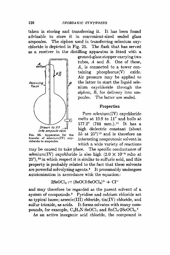
136 I NORGA N IG SYNTHESES
taken in storing and transferring it. It has been found advisable to store it in convenient-sized sealed glass ampoules. The siphon used in transferring selenium oxy- chloride is depicted in Fig. 25. The flask that has served as a receiver in the distilling apparatus is fitted with a
ground-glass stopper carrying two tubes, A and B. One of these, A , is connected to a tower con- taining phosphorus(V) oxide. Air pressure may be applied to the latter to start the liquid sele- nium oxychloride through the siphon, B , for delivery into am- poules. The latter are sealed.
FIG. 25. Apparatus for the transfer of selenium(1V) oxy- chloride to ampoules.
Properties
Pure selenium(1V) oxychloride melts a t 10.9 to 11" and boils a t 177.2" (744 mm.).I1 It has a high dielectric constant (about 55 at 25O)I2 and is therefore an interesting nonprotonic solvent in which a wide variety of reactions
may be caused to take place. The specific conductance of selenium(1V) oxychloride is also high (2.0 X mho a t 25O),ls in which respect it is similar to sulfuric acid, and this property is probably related to the fact that these solvents are powerful solvolyzing agents. It presumably undergoes autoionization in accordance with the equation :
2SeOC12 c (SeOC1-SeOC12)+ + C1-
and may therefore be regarded as the parent solvent of a system of compound^.^ Pyridine and calcium chloride act as typical bases; arsenic(II1) chloride, tin(1V) chloride, and sulfur trioxide, as acids. It forms solvates with many com- pounds, for example, C5HSN-SeOCl2 and SnC14-2SeOCL.
As an active inorganic acid chloride, the compound is!

CRYSTALLINE SELENIC ACID 137
subject to rapid solvolysis when brought into contact with water, alcohols, ammonia, and amines. It is miscible with chlorinated hydrocarbons.
References
1. BAKER and hflucsoN: INORGANIC SYNTHESES, 1, 119 (1939). 2. CAMERON and MACALLAM: Chem. News, 69, 267 (1889). 3. JACKSON and SMITH: J . A m . Chem. SOC., 62, 543 (1940). 4. LATIMER and HILDEBRAND: “Reference Book of Inorganic Chemistry,”
5. LEKHER: J . Am. Chem. SOC., 42, 2498 (1920). 6. MAXSON: ISORGASIC SYNTHESES, 1, 147 (1939). 7. MICHAELIS: Ann., 240, 150 (1887). 8. MUEHI.UERGER and I z w m R : J . Am. Chem. SOC., 47, 1842 (1925). 9. SmTIi: Chem. hh?., 23, 165 (1938). 10. WEBER: Pogg. Ann., 108, 615 (1859). 11. LENHER, SXIT~I, and TOWNE: J . Phys. Chem., 26, 156 (1922). 12. Sm-raE, IA~wrs , GROSSMAX, and JENNISGS: J. Am. Chem. soc., 62, 1219
13. JULIEK: ibid., 47, 1799 (1925).
p. 205, The Macmillan Company, New York, 1933.
(1940).
36. CRYSTALLINE SELENIC ACID
SeOz + H 2 0 2 + HzSeOa SUBMITTED BY 1~. I. CILBERTSON* AND c. B. KING* CHECKED BY s. T. TYREE J R . t
Selenic acid has been prepared in a number of ways,6 all of which are laborious, and only a few of which yield the concentrated acid in a statc of high purity. Several author^'-^*^* 12* lS* l9 have prepared solutions of heavy-metal selenates and then precipitated the metal with hydrogen sulfide to give a dilute solution of the acid. The selenates were usually prepared by oxidation of the corresponding selenites with chlorine. 0 thers 3* 4* 14* 16* have oxidized suspensions of silver selenite with free halogen, then pre- cipitated the silver halide to yield dilute solutions of selenic acid that could be concentrated by *evaporation. Still ~ t h e s ~ ~ ~ ~ ‘ ~ have elcctrolyzed solutions of selenates to effect removal of metallic ions, but this method has never been
* The State College of Washington, Pullman, Wash. t The University of North Carolina, Chapel Hill, N.C.

138 INORGANIC SYNTHESES
considered to be a satisfactory one. Anodic oxidation of selenious acid solutions effects only incomplete oxidation and produces elementary selenium at the cathode. 4,8*11
Meyer and Heiderl' oxidized selenium(1V) oxide to selenic acid with hydrogen peroxide (30 per cent), but used other methods to prepare the concentrated acid.
Selenic acid is conveniently prepared by the oxidation of selenium(1V) oxide with 30 per cent hydrogen peroxide.' Water a+d selenious =id are the only possible impurities. The former can be removed effectively by evaporation under reduced pressure; the latter is present in small amount.
Procedure
One hundred fifty grams of resublimed selenium(1V) oxide16 (synthesis 33) is dissolved in 100 ml. of distilled water in a round-bottomed flask of 1-1. capacity fitted with a standard taper joint. Five hundred grams of 30 per cent hydrogen peroxide (inhibitor-free) * is added slowly. A n upright condenser is then attached (through an all-glass connection) to the flask and the mixture refluxed for 12 hours, during which time a stream of oxygen is passed through the solution to avoid bumping and to maintain an oxidizing atmosphere.
The refluxed selenic acid solution is transferred to a still so arranged as to permit a slow stream of dried air to pass through the solution. Concentration of the solution by the removal of water is first carried out, using a water aspirator, and continued until the solution temperature has reached 150' (about 4 hours). A product containing 85 to 90 per cent selenic acid is obtained in this manner. Further dehydration may be accomplished by distillation at 1- to Zmm. pressure and at temperatures not higher than 1 6 0 O . t It is essential that overheating of the distilling
Buffalo Electrochemical Company, Buffalo, N.Y. t It is essential that this stage of the distillation be controlled very we-
fully, as temperaturea in excess of 165' will cause decomposition of the selenic acid, according to the equation: HZSe04 + H20 + SeOz + %Or.

CRYSTALLINE SELENIC ACID 139
flask on the sides above the liquid level be avoided, as drops of selenic acid may be decomposed on this surface. A coil heater under the flask is therefore more desirable than immersion in an oil bath. Such distillation is continued until water no longer condenses in the receiver. If the selenic acid is not sufficiently dehydrated and even a few tenths of a per cent of water remains in the product, crys- tallization will be difficult.
After the final concentration, crystallization of selenic acid is effected by seeding. Solid selenic acid for seeding purposes may be obtained by cooling a portion of the acid with solid carbon dioxide. It is desirable that the seeding take place at a temperature somewhat below room tempera- ture (10 to 15"). Crystallization of the solid is best carried out in a desiccator over some very efficient drying agent. The crystalline acid is dried by passing dry air [from phos- phorus(V) oxide towers] over the crystals at a low pressure (5 mm.). The product contains 97 to 98 per cent selenic acid by analysis (the remainder being unoxidized selenious acid). Typical yields vary from 187 to 191 g., correspond- ing to 96 to 97.5 per cent of the theoretical based on sele- nium(1V) oxide as starting material.
Properties
Selenic acid is an extremely deliquescent crystalline solid melting at 55 to 58". The specific gravity of 99 per cent selenic acid is 2.59 (20").8 At least two solid hydrates are known, H2SeO4-H20 and H&304.4H20. The acid is simi- lar to sulfuric acid with respect to ionization in water. It is, however, more easily reduced than sulfuric acid, moder- ately strong solutions of hydrochloric acid being sufficient to reduce selenic to selenious acid. Selenates are usually isomorphous with the corresponding sulfates.
References
1. BENGER: J . Am. Chem. Soc., 89,2171 (1917). 2. CAMERON and MACALLAM: Chem. News, 69,219,232,258,267 (1889).

140 INORGANIC SYNTHESES
3. DIEMER and LENHER: J . Phys. Chem., 13, 505 (1909). 4. DENNIS and KOLLER: J . Am. Chem. Soc., 41, 949 (1919). 5. VOK GERICHTEN: Ber., 6, 162 (1873). 6. GILBERTSON: Northwest Sc i . , 6, 83 (1931). 7. GILBERTSON and KING: J . Am. Chem. Soc., 68, 180 (1936). 8. GLAUSER: Chem. Zlg., 31, 630 (1907).
10. METZNER: Compt. rend., 127, 54 (1898). 11. MEYLR and HEIDER: Bet., 48, 1154 (1915). 12. MErER and ~IOI.DENHAU~;R: z. amrg. allgem. Chern., 116, 193 (1921). 13. MITSCHERLICH: Pogg. Ann., 9, 623 (1827). 14. MORRIS: Trans. Wisconsin Acad. Sci., 19(I), 369 (1018). 15. NAESER: INORGANIC SYKTHESES, 1, 117 (1939); 16. STONE: J . Am. Chem. Soe., 46, 29 (1923). 17. THObISEN: Be?-., 2, 598 (1869). 18. WEBER and KING: INORGANIC SYNTHESES, 1, 101 (1939). 19. WOHLWILL: Ann., 114, 169 (1860).
9. MATHERS: J . Am. Chem. S O C . , 50, 1374 (190s).
36. TELLURIUM(IV) CHLORIDE
(Tellurium Tetrachloride)
Te + 2CI2+ TeCL
SUBMITTED BY JOHN F. SUTTLE* AND CHARLES R. F. SMITH* CHECKED BY A. 1). hICELROY,t bv. E. B E N N E l T , t AND J. KLEINBERGt
Tellurium(1V) chloride is most conveniently prepared by the direct union of the elements,' but is also obtainable by the reaction of elemental tellurium or tellurium(1V) oxide with various anhydrous chlorides such as sulfur chloride, iron(II1) chloride, and selenium(1V) chloride. 2-4 Tellu- rium of 99.95 per cent purity and chlorine of similar purity are easily obtainable. The absence of other reaction prod- ucts in the direct union simplifies the purification problem.
Procedure
The all-glass apparatus depicted in Fig. 26 is constructed of such size that it will fit completely into a small oven to
* University of Portland, Portland, Ore. t University of Kansas, Lawrence, Kans.

TELLURI U M ( I V ) CHLORIDE 141
facilitate drying. The apparatus is dried for 12 hours at 100". The size of the flask and the number of ampoules can, however, be varied depending upon the total amount and size of the samples of tellurium(1V) chloride desired.
Fifty grams (0.392 mol) of tellurium is placed in the flask immediately upon removal from the oven. The flask is stoppered and a slow stream of chlorine is introduced through the 8-mm. side tube shown in the figure. A
Fro. 26. Apparatus for the preparation of telluriurn(1V) chloride.
Bunsen burner flame may be necessary to initiate the reac- tion. When the reaction has started, heat is no longer necessary in the early stages. The presence of tellu- rium(I1) chloride is indicated by the murky black liquid that first forms, and by the brown vapor [resembling nitro- gen(1V) oxide] present above the liquid when heat is applied. As soon as an excess of chlorine has been added to complete the conversion of the tellurium to the tetra- chloride, the liquid changes to a dark red color and becomes clear. A yellow vapor is produced by heating the red liquid. This condenses on the cool part of the apparatus

142 INORUANIC SYNTHESES
and solidifies into a yellowish-white crystalline material. The tellurium(1V) chloride is distilled into the ampoules and the ampoules sealed off. The slow stream of chlorine is continued throughout the distillation and sealing opera- tions. Conversion is quantitative. With care in distilla- tion, yields above 95 g. (90 per cent) are readily obtainable.* Anal. Calcd. for TeClr: Te, 47.36; C1, 52.64. Found: Te, 47.9, 47.76; C1, 53.34; 53.70.
Properties'
Tellurium(1V) chloride is a white crystalline solid at room temperature. It melts at 225" and boils at 390" at 755.6 mm. pressure. It hydrolyzes readily when exposed to moist air. Solubility data indicate that it is a polar compound. Molecular-weight measurements give a value of 290.3 at UO", which decreases as the temperature is raised to a value of 246.6 at 595". (Formula weight of TeCl, is 269.) Vapor pressure data indicate very little association.
The density of liquid tellurium(1V) chloride at 232" is 2.559 g./ml.; at 427" it is 2.260 g./ml. The surface tension at 238" is 40.2 dynes/cm.; and at 413.5" it is 26.9 dynes/cm. The heat of vaporization is 18,400 cal./mol.
References
1. SIMONS: J . Am. Chem. Soc., 62,3488 (1930). 2. L E I N ~ B and HILL: &id., SO, 737 (1908). 3. LENHEX: ibid., 80, 741 (1908). 4. h N H E B : &id., d8,29 (1921).
The precautions to be observed in preparation of tellurium(1V) chloride may be summarized aa follows: (1) completely anhydrous conditions; (2) a aide arm 20 to 25 mm. in diameter on the flask to prevent plugging by. depoaition of solid tellurium(1V) chloride; (3) a slow stream of chlorine to prevent exceesive entrainment of tellurium (IV) chloride, which may blow the glaw wool plug out of the outlet and lower the yield; (4) location of the aide arm about an inch above the bulb of the flask so that heating wil l not be exceaaive. Constrictions in the ampoules at the aealing-off place are not neceseery since the operation is carried out at atmospheric pressure and the tellurium(1V) chloride does not affect the properties of the glses.

TELLURIUM(IV) O X I D E 143
37. TELLURIUM(IV) OXIDE
(Tellurium Dioxide)
Te + 2[0]+ TeOz
SUBMITTED B r H. MARSHALL* CHECKED BY A. J. I<INGt AND THOMAS HARRt
Tellurium(1V) oxide has been prepared by the combus- tion of elementary tellurium, and by the ignition of telluric acid. The usual methods, first employed by Beraelius, involve either ignition of so-called “basic tellurium nitrate,” 2TeO2-HNO3, or hydrolytic precipitation from hot nitric or hydrochloric acid solutions. When adequately pure tellurium is the raw material, the hydrolysis of a concen- centrated hydrochloric acid solution is a simple and efficient method; unfortunately, aome commercial grades of tellu- rium contain antimony and bismuth as major impurities. The method given below is designed to give both high purity and high yield irrespective of the initial purity. A unique feature is the solution of the tellurium fairly free of asso- ciated impurities at the outset. Succeeding steps involve the fractional precipitation of bismuth and antimony, the crystallization of basic tellurium nitrates, and finally decom- position at temperatures above 30003 to yield tellurium(1V) oxide. Lead, when present in small amounts, and other possible heavy-metal contaminants are soluble in nitric acid of high concentration.
Procedure
Twenty grams of commercial tellurium (finer than 60 mesh) is weighed into a 1000-ml. beaker, covered with 200 ml. of water, and treated by the slow addition of 95 ml. of concentrated nitric acid (sp. gr. 1.42). The reaction is
* Canadian Copper Refinem Limited, Montreal East, Quebec. t Syracuse University, Syracuse, N.Y.
Inorganic Syntheses, Volume 111 Edited by Ludwig F. Audrieth
Copyright © 1950 by McGraw-Hill Book Company, Inc.

I44 I NO RG.4 N I C S Y NT H ESES
allowed to continue for 5 to 10 minutes* with occasional agitation. Insoluble impurities are removed immediately by filtration on a Buchner funnel. The filtrate is trans- ferred to a 600-ml. beaker.
Sixty-five milliliters of concentrated nitric acid is then added and the solution boiled until oxides of nitrogen have been expelled. Basic nitrates of antimony and bismuth precipitate a t this point if these substances are present as impurities. These are removed by filtering through asbes- tos, after which the clear liquor is evaporated gently on a water bath under a hood in an open 600-ml. beaker. Basic tellurium nitrate is deposited. The evaporation is con- tinued until the solution volume has been reduced to 100 ml. The solution is then cooled. The crystalline deposit is filtered, washed with water on a suction filter, and airdried.
The crystals are placed in a 400-ml. beaker, covered by inverting a 1000-ml. beaker over the other, and heated at a hot-plate temperature of 400 to 430" for 2 hours. The tellurium(1V) oxide is cooled and bottled immediately to avoid slow darkening due to reduction by organic matter from the atmosphere. In a typical experiment, 21 g. of TeOz (84 per cent of theory) was obtained from a tellurium sample containing: Cu, 0.05 per cent; Fe, 0.015 per cent; Pb, 0.005 per cent; Se, 0.05 per cent; alloyed with 0.3 per cent each As, Sb, and Bi. The product was found to con- tain: Te, 79.91 per cent (theory 79.95 per cent); Cu, 0.00002 per cent; Fe, 0.0007 per cent; Pb, 0.0018 per cent; Se, As, Sb, and Bi, less than 0.001 per cent.
Properties
Tellurium(1V) oxide is a white solid existing in two crys- talline forms, the tetragonal (sp. gr. 3.66), obtained by hydrolysis or ignition of the nitrate below 350", and the
* Many samples of tellurium contain selenide and telluride impurities which are attacked if the reaction time is extended. By limiting the reac- tion time some purification can be effected in the initial step. (H. M.)

TELLURIC ACID 145
rhombic (sp. gr. 3.93), obtained at higher temperatures. On heating, tellurium(1V) oxide becomes yellowish and finally melts at a dull red heat to a deep yellow liquid. The exact melting point is not known.
It is perceptibly soluble in water to give a neutral solu- tion. It is soluble both in sodium hydroxide solutions and in hydrochloric acid. It is converted into a basic tellurium sulfate by heating to the appearance of white fumes with sulfuric acid.
1. BERZELIUS: Pogg. Ann., 32, 15 (1834); Ann. chim. phys., [2] 68, 129
2. KOTHNER: Ann., 319, 1 (1901). 3. NORRIS: J . A m . Chem. Sac., 28, 1675 (1906).
References
(1835).
38. TELLURIC ACID
5TeO2 + 2KMnOa + GHNO, + 12HL0 4 5H6TeOe + 2KN03 + 2Mn(N0J2
S r J B M I n E D BY FRANK c. hfATIIERR, * CHARLES bf. RICE, * HOWARD BROD- ERICK,* AND ROBERT F o n s E Y *
CHECKED BY A. J. KrsGt AND T. Hannt
Although similar to sulfur dioxide in many ways, tellu- rium(1V) oxide cannot bc oxidized to the hexavalent state by nitric acid. While many of the strongcr oxidizing agents will accomplish this oxidation, potassium permanganate in a nitric acid solution is preferred' since the by-products of this reaction are sufficiently soluble in water and in nitric acid solution to make possible a satisfactory separation from the telluric acid which is only slightly soluble in water and very insoluble2 in concentrated nitric acid.
Procedure
Five grams of potassium permanganate is dissolved in 100 ml. of water and the resulting solution added slowly
* Indiana University, Bloomington, Ind. t Syracuse University, Syracuse, N.Y.

146 INORGANIC SYNTHESES
with vigorous stirring, in 5-ml. portions at 5-minute inter- vals, to a boiling suspension of 10 g. of tellurium(1V) oxide* (synthesis 37) in 40 ml. of concentrated nitric acid and 100 ml. of water. Some manganese(1V) oxide is pro- duced with each addition of permanganate. It is possible, but not necessary, to effect its solution, except near the end, by boiling for a sufficient time after each portion of per- manganate has been added.t After all the permanganate has been added the solution is kept at the boiling point for 50 minutes in order to reduce the amount of manganese(1V) oxide. Three per cent hydrogen peroxide is then slowly added until the remaining manganese(1V) oxide goes into solution. About 50 ml. will be required.
The clear solution is evaporated until its weight has been decreased to about 60 g. Ten milliliters of concentrated nitric acid is added and the solution allowed to stand for 24 hours. The mother liquor is decanted from the crystals, evaporated to a weight of 25 g., and again treated with 10 ml. of concentrated nitric acid. A second crop of crys- tals is obtained after an additional 24 hours.
The combined crops of crystals are washed with three portions of 10 ml. each of concentrated nitric acid and drained as completely as possible after each washing. A centrifuge is desirable in conducting this washing operation. The product is then purified by crystallizing from a hot mixture of 25 ml. of water and 17 ml. of concentrated nitric acid.$ These crystals should be washed with nitric acid,
Crude tellurium dioxide can be used with equally good results, if the sand and other insoluble materials are removed by filtration following the addition of the hydrogen peroxide.
t The amount of manganese(1V) oxide remaining in the reaction mixture at the end depends upon (1) the exceas of permanganate used, (2) the rate of addition of the permanganate, and (3) the time of boiling between additions of the permanganate. As the insoluble tellurium(1V) oxide is oxidized to soluble telluric acid, the solution gradually becornea free of any precipitate except for the manganese(1V) oxide.
$ If a high yield ie not important, it is recommended that the product be recrystallized from water after one recrystallization from the nitric acid.

TELLURIC ACID 147
preferably by centrifugation. High-purity telluric acid is obtained after a third recrystallization, followed by removal of adhering water and nitric acid from the centrifuged crystals by heating to 100" for 1 hour, then crushing and grinding and reheating for 15 minutes to remove occluded mother liquor. The final crystals have a purity of 99.85 per cent. The over-all material yield will vary from 11 to 12.5 g., or 76.5 to 86.8 per cent. If large, well-formed crystals are desired, it is necessary to effect their formation from water solution; the solubility of the telluric acid in nitric acid is so small that large crystals cannot be produced easily. Crystals from water solutions arc more easily freed from solvent than those obtained from nitric acid.
Analysis
Telluric acid can be titrated as a monobasic acidg with standard sodium hydroxide using phenolphthalein as an indicator, if an equal volume of glycerol is added. If any nitric acid is present, it must be neutralized first with sodium hydroxide, using methyl orange as indicator.
Properties
Telluric acid, HzTeOa-2Hz0, has a solubility2 at 25" of 0.97 g. per 100 ml. in nitric acid containing 57.39 g. HNO, per 100 ml. of solution, and 35.8 g. in a nitric acid containing 8.63 g. of HNO, per 100 ml. The first ionization constant has a value of K A = 6 X lo-'. It is a weak acid and a weak oxidizing agent, Only the alkali metal and ammo- nium salts are soluble in water. It is stable below about 140".
References
1. MATHERB, Rrcn, BRODERICK, and FORNEY: Proc. Ind. A d . Sci.,62,
2. MATHERS and RICE: ibid., 82, 117 (1943). 3. RO8ENHEIM and WEINHEBER: 2. anotg. Chem., 60, 266 (1910); cf. chem.
114 (1943).
Abstracts, 6, 1378 (1911).
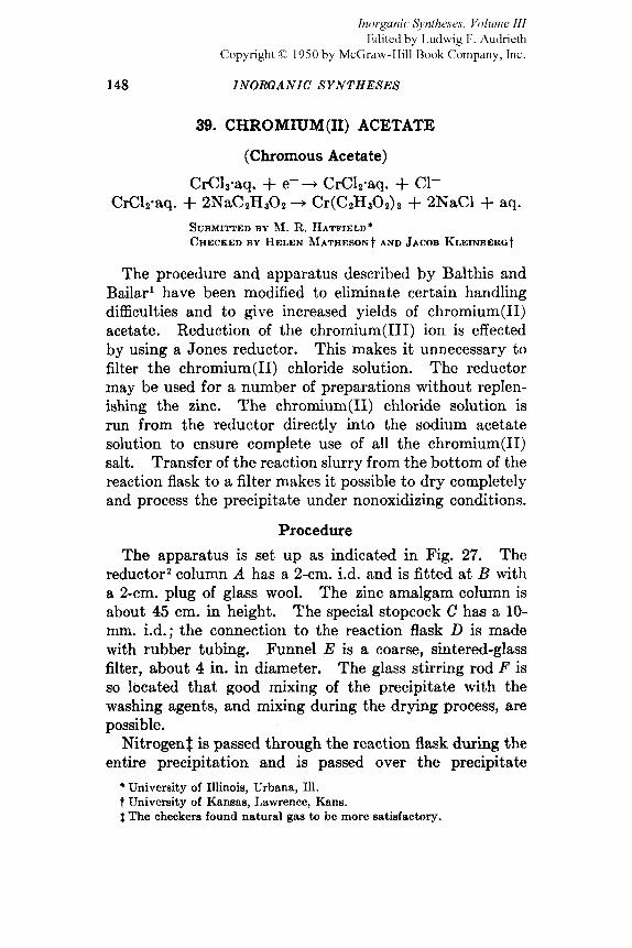
148 INORGANIC SYNTHESES
39. CHROMT[TM(II) ACETATE
(Chrornous Acetate)
CrCI3-aq. + e-+ CrCl2.aq. + C1- CrClP.aq. + 2NaCzH302 + Cr(C2H302)2 + 2NaC1 + aq.
SUBMITTED BY 31. R. I~ATFIELD' CHECKED BY HELEN hfATHESOHt AND JACOB KLEr-ERCt
The procedure and apparatus described by Balthis and Bailar' have been modified to eliminate certain handling difficulties and to give increased yields of chromium(I1) acetate. Reduction of the chromium(II1) ion is effected by using a Jones reductor. This makes it unnecessary to filter the chromium(I1) chloride solution. Thc reductor may be used for a number of preparations without replen- ishing the zinc. The chromium(I1) chloride solution is run from the reductor directly into the sodium acetate solution to ensure complete use of all the chromium(I1) salt. Transfer of the reaction slurry from the bottom of the reaction flask to a filter makes it possible to dry completely and process the precipitate under nonoxidizing conditions.
Procedure
The reductor2 column A has a Z-cm. i.d. and is fitted at B with a 2-cm. plug of glass wool. The zinc amalgam column is about 45 cm. in height. The special stopcock C has a 10- mm. id . ; the connection to the reaction flask D is made with rubber tubing. Funnel E is a coarse, sintered-glass filter, about 4 in. in diameter. The glass stirring rod F is so located that good mixing of the precipitate with the washing agents, and mixing during the drying process, are possible.
Nitrogen$ is passed through the reaction flask during the entire precipitation and is passed over the precipitate
The apparatus is set up as indicated in Fig. 27.
* University of Illinois, Urbana, Ill. t University of Kansas, Lawrence, Kans. 4 The checkers found natural gas to be more satisfactory.
Inorganic Syntheses, Volume 111 Edited by Ludwig F. Audrieth
Copyright © 1950 by McGraw-Hill Book Company, Inc.

C H R O M I U M ( I I ) ACETATE 149
during filtration. The nitrogen is freed from oxygen by passing it through towers filled with alkaline pyrogallol and ammoniacal copper(1) chloride.
The zinc is amalgamated for use in the Jones reductor by stirring a quantity of 10- to 20-mesh zinc for 10 minutes in
FIQ. 27. Arrangement of apparatus for the preparation of chromium(I1) acetate.
a solution containing 0.1 M mercury(I1) chloride in . l M hydrochloric acid. The zinc column is washed thoroughly with water and then with a small quantity of 1 N sulfuric acid. The liquid level in the reductor is at all times kept above the top of the zinc column.
Ninety grams of chromium(II1) chloride 6-hydrate is dissolved in 120 ml. of water and 30 ml. of 2 N sulfuric acid. The solution is poured into the reductor column and
150 INORGANIC S Y N T H E S E S
the rate of flow through the column adjusted by stopcock G so that the chromium salt solution dropping into the reac- tion flask D is bright blue in color. As soon as this condi- tion is achieved, a filtered solution of 252 g. of sodium acetate in 325 ml. of water is added to the reaction flask through H . The mixture in the reaction flask D is stirred for short periods during the precipitation.
When precipitation is complete, nitrogen (or natural gas) is passed through funnel E and stopcock C is opened. By careful regulation of the nitrogen rate a slight suction may be applied to filter flask J so that only nitrogen passes through the precipitate. The precipitate is washed with freshly boiled distilled water which is introduced a t K . Drying is carried out by washing with alcohol and then with ether, the Iast traces of ether being removed by the stream of nitrogen. The chromium(I1) acetate precipitate, which is a deep red powder, must be completely dry* before exposure to the air, as it oxidizes very rapidly when moist to the deep violet chromium(II1) salt. The yield is 55.0 g., or 95 per cent of the theoretical based on CrCl3.6H2O.
References
2. PIERCE and HAENI~CH: “Quantitative Analysis,” 3d ed., p. 225, John 1. BALTHIS and BAILAR: INORGASIC SYNTHESES, 1, 123 (1939).
Wiley & Sons, Inc., Sew York, 1948.
40. ANHYDROUS CHROMIUM@) CHLORIDE
(Chromous Chloride)
2CrCla + Hz - 2CrC12 + 2HC1
SUBMITTED BY ANTON B. Burtot CHECKED BY RALPH C . YOUNOS AND CHAUNCY STARRS
Anhydrous chromium(I1) chloride has been prepared by three essentially different methods: (1) by treatment of
stable product. * A 24-hour drying period wag found to be necessary in order to produce a
t University of Southern California, Los Angeles, Calif. $ Massachusetts Institute of Technology, Cambridge, Mass.
(H. M. and J. K.)

ANHYDROUS C H R O M I U M ( I I ) CHLORIDE 151
anhydrous chromium(II1) chloride with hydrogen at red (2) by the action of hydrogen chloride upon metallic
chromium3p4; and (3) by the dehydration of hydrated chro- mium(I1) chloride in vucuo at 180°.6 The last method does not give a pure product; oxidation, hydrolysis, or both occur. The product of the second method is often con- taminated with metal.6 The first method is best; partial reduction to metal may occur but can be prevented by using a mixture of hydrogen and hydrogen chloride. 'I
Procedure A A Vycor or silica tube, 60 cm. long with a 15-mm. bore, is
baked for 1 hour at 450" while a current of dry hydrogen chloride is passed through it. The tube is cooled and the hydrogen chloride is replaced by dry air. Five grams of anhydrous chromium(II1) chloride* is introduced into the tube and purified by sublimation in a current of dry chlorine or dry hydrogen chloride at 800". The gas stream is adjusted to pass at a rate of 20 to 30 ml. per minute, this rate of flow providing for the formation of large flakes. Iron(II1) chloride that may appear is sublimed and caused to collect at the end of the tube. After it is removed, the purified chromium(II1) chloride that is deposited at the end of the furnace can be obtained.
The apparatus employed for the reduction is shown in Fig. 28. A Pyrex reaction tube 2.5 X 50 cm., pre- viously heated in oucuo at 500", is fitted with a two-hole rubber stopper carrying an outlet tube A and the longer tube B, 8 mm. in diameter, for leading the gases to the closed end; this tube should slip rather easily into the rubber stopper. The sublimed chromium(II1) chloride is spread out toward the closed end of the reaction tube and the latter is placed in an electric resistance furnace, the tem- perature of which can be measured with a thermocouple. Dry oxygen-free hydrogen and hydrogen chloride, each at the rate of 50 ml. per minute, are passed first into a T-tube where they mix, and then led to the closed end of the

152 INORGANIC SYNTHESES
reaction vessel.* To the exit tube A is attached a drying tube containing anhydrous calcium chloride. The reduc- tion is carried out at 500”. The furnace may be slipped off at intervals to inspect the product, which is white when pure.
After the reaction is complete, the furnace is cooled to room temperature and a current of dry carbon dioxide or dry nitrogen is substituted for the hydrogen-hydrogen chloride mixture. The delivery tube is pulled through the rubber stopper until the end passes the constriction C at which the apparatus is then sealed.
Asbeshs plug
F u r n a c e
FIQ. 28. Apparatus for effecting reduction of chromium(II1) chloride.
The larger stopcock D has a 10-mm. bore. Through it the product can be transferred as needed, provided this operation is carried out in an atmosphere of a dry inert gas such as nitrogen or carbon dioxide which can be introduced through the small stopcock E.
Procedure B This synthesis can also be accomplished by using a
column of chromium(I1) chloride as a “getter” for a second column of the salt. A Vycor tube, 90-cm. by 13-mm. bore, baked out as described in procedure A, is used for this purpose. Sublimed chromium(II1) chloride is introduced in such a way that two columns are formed, each being 10 cm. long and separated from each other by a distance of 20 cm. The materials are held in place by glass wool. Two Hoskins furnaces (hinged type) are used in line, a
. * The procedure described by McCoy, INORGANIC SYNTHESES, 2, 72, (1946) may also be used for producing a 1 : l mixture of hydrogen and hydrogen chloride.
HEXAMMINECHROiMI(lnl(III) NITRATE 153
column of salt being located at the center of each furnace. The salt is sublimed at 800" in a current of hydrogen chlo- ride and cooled in a current of the gas. The position of each furnace is then changed so that again the chloride is at the center. The reduction is carried out with a mixture of hydrogen and hydrogen chloride at 500", as described in procedure A. When reduction is complete, the furnaces are cooled to room temperature and dry carbon dioxide is substituted for the hydrogen-hydrogen chloride mixture. The product can then be transferred in a current of carbon dioxide into a suitable container.
Properties
Pure anhydrous chromium(I1) chloride forms white hygroscopic needles that are stable in dry air but oxidize rapidly if moist. The compound dissolves in water, form- ing the blue hydrated chromium(I1) ion which has strong reducing properties. Several hyclrates5~'0 and ammines7 have been described.
References
1. MOBERG: J . prakt. Chem., 29,475 (1843); 44, 322 (1848). 2. PELIGOT: Ann. chim. phys., [3] 12, 528 (1844). 3. UFER: Ann., 112, 302 (1859). 4. MOISSAX: Compt. rend., 92, 792 (1881). 5. KNIGHT and RICH: J . Chem. SOC., 99, 89 (1911). 6. KOPPEL: Z . anorg. Chem., 46, 359 (1905). 7. SCHLESINGER and HAMXOND: J . A m . Chem. SOC., 66,3971 (1933). 8. HEISIO, FAWKES, and HEDIN: IXORGAMC SYNTHESES, 2,193 (1946). 9. M n s o ~ : ibid., 1, 147 (1939). 10. BALTEIS and BAILAR: ibzd., 125 (1939).
41. HEXAMMINECHROMrtJM(1II) NITRATE NaNHa
CrCla + 6NH3 2 [Cr(NHJ B I C ~ ~ [Cr(NH3)B]C13 + 3HN03 + [Cr(NHs)~](N03)3 + 3HC1
SUEMIWED BY A. L. OPPEGARD* AND J. C. BAILAR, JR.* CHECKED BY JACOB KLEINBERGt
By the action of liquid ammonia on anhydrous chro- mium(II1) chloride, Christensen' prepared a mixture of
* University of Illinois, Urbana, Ill. t University of Kansas, Lawrence, Kans.
154 INORGANIC SYNTHESES
chloropentamminechromium(II1) chloride and hexammine- chrornium(II1) chloride. Separation was effected by extrac- tion of the soluble hexammine, which was then precipitated as the nitrate by the addition of concentrated nitric acid.
RolIinson and Bailar prepared hexamminechromium(II1) nitrate in low yield by treating anhydrous chromium(II1) sulfate with liquid ammonia in the presence of ammonium nit-rate. They also prepared the hexammine by dissolving chloropentamminechromium(II1) nitrate in liquid ammonia containing a little sodium amide. The following procedure utilizes the observation of Rollinson and Bailar that sodium amide (a base in liquid ammonia) catalyzes the ammona- tion of the chloropentamminechromium(III) ion.
Procedure
(Caution. U s e a well-uentilated hood.) About 800 ml. of liquid ammonia is introduced into a
1-1. Dewar flask, or a 1000-ml. beaker that is placed within a 1500-ml. beaker, and 0.5 g. of clean sodium metal and 0.2 g. of iron(I1) ammonium sulfate are addede3 After the blue color of the sodium hasdisappeared, 50 g. (approxi- mately 0.3 mol) of anhydrous chromium(II1) chloride4 is added in 2-g. portions, while the solution is constantly stirred. After the addition has been completed (1 to 2 hours), the brown precipitate is allowed to settle, and the clear, slightly colored supernatant liquid is decanted from the beaker or siphoned from the Dewar flask.
The residue is transferred to a large crystallizing or evaporating dish and is allowed to stand with occasional stirring until the odor of ammonia is gone and a bright yellow, freely flowing powder remains.* The yield of impure [Cr(NH3) &13 is about 80 g. (nearly quantitative). For purification, the material is quickly dissolved in a mixture of 150 ml. of water and 10 ml. of concentrated hydrochloric acid at 40°, and filtered. The filtrate is
* Hexamminechromium (111) salts are slightly photosensitive and should be protected from direct sunlight.

HEXAMMINECHROMIUM(III) NITRATE 155
immediately treated with 50 ml. 'of concentrated nitric acid and is cooled to room temperature. Pure hexammine- chromium(II1) nitrate precipitates. After standing for a few minutes, the bright yellow, crystalline salt is collected on a Buchner funnel and is washed with cold distilled water containing a little nitric acid, then with alcohol, and finally with ether. The product is dried in a vacuum desiccator protected from strong light, and is stored in a brown bottle. The yield of hexamminechromium(II1) nitrate is 80 g. (75 per cent).
Properties The other salts of the series, except the normal sulfate,
can be prepared by metathesis. In the dry state the salts are stable unless exposed to light or heated above loo", a t which temperature slow decomposition begins. The chlo- ride, sulfate, and nitrate are moderately soluble in water a t room temperature, the solubility of the nitrate being 1 part in 40 parts of water. The nitrate is only sparingly soluble in the presence of nitric acid. Since neutral solutions decompose slowly upon standing at room temperature and rapidly at elevated temperatures, care should be taken to perform crystallizations rapidly and at moderate temperatures.
When heated in the presence of hydrochloric acid, the hexammine salts are converted to chloropentamminechro- mium(II1) chloride, [Cr(NHs) &l]Cl,. A pronounced tend- ency to form double salts exists. For example, the chlo- ride forms a double salt with mercury(I1) chloride; and the nitrate in the presence of the sulfate ion reacts to form the sparingly soluble compound [Cr(NHJ 6](S01) (NOa). For this reason, the normal sulfate must be made from the hydroxide of the series.
References
1. CHRISTENSEN: 2. a m g . Chem.. 4,229 (1893). 2. ROLLINSON and BAILAR: J . Am. Chem. Soe., 66,250 (1943). 3. GREENLEE and HENNE: INOBQAKIC SYNTHESES, 2,128 (1946). 4. HEIBIQ, FAWKEB, and HEDIN: am., 193 (1946).
156 INORGANIC SYNTHESES
42. CHROMIUM HEXACARBONYL
CrC13 + C6H6MgBr 5 [complex] 2 Cr(CO)a
SWMITTED BY B. B. OWEN, * J. ENGLISH, JR., * H. G. CASSIDY, * AND C. V.
CHECKED BY G. CALINGAERT~ AND V. F. HUIZDA~ DUNDON*
Chromium hexacarbonyl has been prepared by the reac- tion of chromium(II1) chloride with phenylmagnesium bromide in the presence of carbon monoxide. lW3 Unsatis- factory yields have been reported and difficulty experienced in repeating the ~ynthes is .~ '~ Unfortunately, no other methods for the preparation of this substance are recorded in the literature.
Procedure A Preparation under Carbon Monoxide Pressure. The
apparatus used is a commercial high-pressure hydrogena- tor1 having a bomb capable of being rocked mechanically under pressure. The bomb is equipped with a liner of glass or metal,§ which has a capacity of 250 ml. of reaction mixture. The bomb liner is fitted with a rubber stopper carrying a mechanical stirrer, inlet and outlet tubes for dry nitrogen, and a large buret or calibrated separatory funnel for addition of the Grignard reagent. The gas inlet hole in the side of the liner is closed with a piece of ordinary adhesive tape. Provision is made for the use of carbon monoxide under tank pressure (500 to 1000 p.s.i.) ; tempera- ture control is unnecessary. The anhydrous chromium (111) chloride6 is dried at 250" in an atmosphere of nitrogen and screened to 40 mesh after drying. The resulting powder is hygroscopic and should be kept out of contact with air as much as possible.
The liner is charged with 3.08 g. of dry chromium(II1)
* Yale University, New Haven, Conn. t Ethyl Corporation, Research Laboratories, Detroit, Mich. 1 American Instrument Company 436 in. series vessel KO. 406225. 0 Liners of glass, steel, and brass have been used successfully.
Inorganic Syntheses, Volume 111 Edited by Ludwig F. Audrieth
Copyright © 1950 by McGraw-Hill Book Company, Inc.

CHROMIUM HEXACARBONYL 157
chloride and 60 ml. of anhydrous ether (dried over sodium). A solution of 27 g. (0.149 mol) phenylmagnesium bromide' in about 80 ml. of dry ether is introduced into the buret and kept under a nitrogen atmosphere.
The liner is now cooled in a Dry Ice-acetone bath to zt
temperature of about -70". The stirrer is operated at about 200 to 300 r.p.m. to keep the chromium(II1) chloride suspended evenly throughout the solution. A nitrogen atmosphere is maintained in the reaction vessel. At this temperature the Grignard reagent crystallizes from solution and little, if any, reaction takes place. The stirring appa- ratus is then detached; the liner is removed from the cooling bath, wiped quickly, closed, and inserted at once into the bomb of the hydrogenator. Thc bomb is sealed at once and placed under a pressure of carbon monoxide (500 to 1000 p.s.i.) and rocking is started. The yield of carbonyl depends to a large extent on getting the reaction mixture under a pressure of carbon monoxide before the contents of the liner reach a temperature of about - 10".
The bomb is rocked for about 2Qi hours, or for about 2 hours after the contents reach room temperature; longer periods are without effect on the yield of carbonyl. No heat is applied to the bomb and relatively little heat of reaction is observed under these conditions.
The carbon monoxide pressure is then released gradually and the contents of the liner transferred to a 3-1. flask con- taining ice water and 35 ml. of 5 N sulfuric acid. Addi- tional ether is sometimes helpful in transferring the material from the reaction vessel to the flask; a good deal of heat is involved in the decomposition of the excess Grignard reagent at this point. The reaction mixture is now steam- distilled using an efficient condenser and a receiver cooled in ice and containing ice water. After the ether has been distilled over, crystals of carbonyl appear in the condenser and are gradually washed into the receiver by the distillate. It is sometimes necessary to increase the steam flow or decrease the flow of cooling water in the condenser to avoid
158 INORGANIC SYNTHESES
clogging the outlet with crystals. Ether is added to the receiver to dissolve all the crystals and the ether layer separated, washed with water, and dried over anhydrous sodium sulfate. The ether is then distilled from the reac- tion product through a good fractionating column (about 15 theoretical plates) ; unless a column is used there is con- siderable loss of carbonyl by volatilization with the ether. Distillation is continued until the volume in the still pot is reduced to 50 ml.; the residue is then cooled in ice and the crystals filtered with suction. The product is washed with cold methanol and finally with a little cold ether and allowed to stand in air to dry.* The yield of practically pure, airdried carbonyl is 1.95 to 2.2 g.t or 45 to 51 per cent of theory based on the amount of chromium(II1) chloride employed.
Further purification of the carbonyl is effected by recrys- tallization from dry ether; this is best accomplished by placing the crude product in the thimble of a Soxhlet extractor and extracting with dry ether. Pure chromium hexacarbonyl crystallizes on cooling; it is filtered and washed as before.
A completely odorless product is obtained by sublimation of the recrystallized carbonyl at 0.5 mm. or less, and at a bath temperature of 40 to 50"; the large, highly refractive crystals are collected in a receiver cooled with Dry Ice. The sublimation apparatus must have a short, wide bore connection between the hot and cold sections to prevent clogging with crystals. The loss of product in the crystal- lization and sublimation processes is slight ; several runs
* The drying in air should not be overdone, as the material is volatile at room temperature and is probably toxic. Loss of carbonyl may be incurred if the ethereal solutions are allowed to stand; a brownish deposit precipi- tates on standing overnight in the dark; decomposition in sunlight is rapid. There is also the possible hazard of violent decomposition if ethereal solu- tions are allowed to stand for extended periods. The authors have been advised by English workers that solutions of molybdenum hexacarbonyl have detonated on standing.
t Yields as high as 67 per cent have been obtained using the apparatus described here,

CHROMIUM HEXACARBONYL 159
are conveniently combined for this operation. Larger scale bomb runs are limited by the capacity of the bomb and the additional time required in getting the mixture under pressure of carbon monoxide.
Procedure B
Preparation at Atmospheric Pressure. A 3-1. five-necked flask is equipped with a high-speed metal* stirrer, a con- denser cooled with Dry Ice and acetone, a gas inlet tube for. carbon monoxide, a thermometer, and a buret for delivering Grignard reagent. Provision is made for exter- nal cooling and the entire apparatus is set up in a good hood. A suspension of 12 g. of anhydrous chromium(II1) chloride in 700 ml. of dry ether is stirred vigorously (5000 r.p.m.) and cooled to -70". Without interrupting the stirring, 210 ml. of 2.7 N phenylmagnesium bromide is added over a period of 1 hour at this temperature. The Dry Ice cooling bath is then replaced with an ice-water bath and a rapid stream of carbon monoxide (220 l./hour) is led into the stirred mixture. The reaction begins at about -10" as indicated by the appearance of a dark color. The reaction is allowed to proceed for 15 to 30 minutes longer at a tem- perature not exceeding 0". At the end of this time the mixture is poured into ice water containing 100 ml. of 6 N sulfuric acid, and the carbonyl isolated as described above for the high-pressure method. Typical yields will average 1.8 g. or 11 per cent of theoretica1.t
Properties
Chromium hexacarbonyl forms large, highly refractive crystals that can be sublimed in vacuum without change but decompose on heating above about 100". The vapor pressure of chromium hexacarbonyl has been measured up to 125°.4 On exposure to light and air at room temperature
* The propeller used was gold-plated steel. t Efficient stirring and a vigorous stream of carbon monoxide will ,help to
achieve yields as high as 24 per cent.

160 I N O R G A N I C SYNTHESES
in the impure solid state or in ether solution it decomposes slowly to a brown powder, but the pure solid can be pre- served indefinitely out of direct sunlight. Chromium hexa- carbonyl is soluble in ether, chloroform, and other organic solvents and insoluble in water and methanol.
References
1 . JOB and CANAL: Compt. rend., 183, 392 (1926). 2. ANISSIMOC and NESMEYANOV: Gompt. rend. acad. sci. (U.S.S.R.), 26, 58
3. OWEN, ENGLISH, CASSIDY, and DUNDON: J . A m . Chem. Soe., 69, 1723
4. HIEBER and ROMBERG: 2. anorg. aZEgem. Chem., 221, 321 (1935). 5. WINDSOR and BLANCHARD: J . Am. Chem. SOC., 66,823 (1934). 6. HEISIG, FAWKES, and HEDIN: INORGANIC SYNTHESES, 2, 193 (1946). 7. ALLEN and CONVERSE: “Organic Syntheses,” Collective Vol. 1, 221
(1940).
(1947).
(1932).
43. POTASSIUM OCTACYANOMOLYBDATE (IV) 2-HYDRATE
(Potassium Molybdocyanide Dihydrate)
KaMo(CN) 8.2H20 SUBMITTED BY N. 11. FURMAN* AND C. 0. MILLER* CHECKED BY P. G. A R V A N t AND L. F. AUDRIETHt
Potassium octacyanomolybdate(IV) may be prepared by the action of potassium cyanide upon certain tri-, tetra-, or pentavalent derivatives of molybdenum. The latter are obtained by ~hemical’~ or electrochemical6 reduction of molybdic acid.
The recommended procedure was first devised by Rosen- heim’ and later modified by Fieser.s The various steps in the synthesis cannot be represented by exact chemical equations but may be outlined diagrammatically as follows :
* Princeton University, Princeton, N.J. t University of Illinois, Urbana, Ill.
POTASSIUM oCTACYANoniOI,YBDATE(ZV) % H Y D R A T E 161
Although not extremely efficient, this procedure is rapid cnd reliable, and requires no special apparatus or technique.
Procedure Fifty grams (0.346 mol) of pure molybdenum(V1) oxide,
Mooa, is dissolved in a solution of 40 g. (0.714 mol) of potassium hydroxide in 100 ml. of water. To this solution is added 250 ml. of concentrated hydrochloric acid. The addition is made slowly and with constant stirring; the final solution is heated on a steam bath.
A concentrated solution of potassium thiocyanate is pre- pared by dissolving 150 g. (1.545 mol) of the salt in 150 ml. of water. This solution is added slowly and with constant stirring to the hot molybdic acid solution. The resulting deep red solution is diluted with 300 ml. of water and heated on a steam bath for 2 hours, with frequent stirring.
The solution is filtered while still warm and the filtrate transferred to a 2-1. beaker. Pyridine is added slowly and with constant stirring until a yellow solid begins to sepa- rate. About 65 to 75 ml. of pyridine will be required. The beaker is then placed in an ice bath until the red oily layer that has settled out on the bottom becomes very viscous. The supernatant liquid, which is still slightly red in color, is decanted and the product washed twice with water.
The oily liquid is treated with a solution of 200 g. (3.07 mols) of potassium cyanide in 300 ml. of water. Caution. T h i s step must be carried out in a well ventilated hood, as noxious gases are evolved. The oily pyridine compound dis- solves rapidly to give first a green and then a yellow-brown solution. This solution is heated on a steam bath, with frequent stirring, for >d hour. A black by-product usually separates from the solution; it is removed by filtration (hood) and discarded. The filtrate is evaporated until its volume has been reduced 50 per cent. The concentrated solution is cooled in an ice bath, and the dark amber crys- tals collected on a Buchner funnel.

162 INORGANlC SYNTHESES
The crude product containing a considerable amount of a black contaminant is dissolved in a minimum amount of warm water (70"), treated with decolorizing charcoal (Darco), and filtered. To the filtrate is added slowly one to two volumes of ethyl alcohol until a golden-yellow crys- talline solid separates. This purification process may be repeated if a product of higher purity is desired. The crystals are collected on a Biichner funnel, washed with alcohol, then ether,* and finally dried in a vacuum.
Further evaporation of the mother liquor yields only small amounts of the product, which becomes increasingly difficult to purify.
The yield is 75 to 85 g. of pure K4Mo(CN),.2H20 (44 to 50 per cent of the theoretical yield based on the molybdic oxide). Three careful recrystallizations will generally suffice to give a salt that, when titrated in dilute sulfuric acid against standard cerium(1V) sulfate using the o-phen- anthroline-iron(I1) complex or Erio Green (naphtalin green V) as indicator, will be found to be 100 per cent pure.
Properties
On heating at 110", the potassium octacyanomolyb- date(1V) 2-hydrate loses its water of hydration. The salt is extremely soluble in water, from which it may be crystal- lized in the form of yellow rhombic bipyramidal crystals, (a:b:c = 0.7028:1:0.3711). It is oxidized by cerium(1V) salt solution to the corresponding octacyanomolybdate(V), K3Mo(CN) Aqueous solutions are photosensitive and, on prolonged exposure to direct sunlight, turn red and then pale green with the evolution of hydrogen cyanide.
References
1. CHILESOTTI: Gazz. chim. ital., 34,11, 493 (1904). 2. BUCKNALL and WARDLAW: J. Chem. SOC., 2983 (1927). 3. ROBENHEIM, GARFUNKEL, and KOHN: Z. anorg. Chem., 66, 166 (1910). 4. JAKOB and TURKIEWICZ: Roczinki Chem., 11, 569 (1931). 5. SAND and BURQER: Ber., 38,3384 (1905).
be prepared by subsequent drying at 100 to 110'. * The washing with ether is important if the anhydrous compound is to

TUNGSTEN(VI) CHLORIDE 163
6. WILLARD and THIELKE: J . Am. C k m . Soc., 67,2609 (1935). 7. ROSENHEIM and Koss: Z. anosg. Chem., 40, 148 (1906); ROSENHEIM:
8. FIESEE: J . Am. Chem. soe., 62,5226 (1930). W., 64, 97 (1907).
44. TUNGSTEN(VI) CHLORIDE
(Tungsten Hexachloride)
WO, + 3 H z 4 W + 3H20 w + 3c124 wc16
SUBMITTED BY M. H. LI$TSKE+ AND M. L. HOLT+ CHECKED BY A. J. VANDER WEYDENt AND J. 11. CALLISONt
Tungsten(V1) chloride has been prepared by heating tungsten(V1) oxide and phosphorus(V) chloride in a sealed
and by the action of chlorine on powdered tungsten metal. 3*4 The latter method is preferred because it permits the removal of molybdenum impurities from the tungsten and also because it avoids the separation of phosphorus(V) oxychloride from tungsten(V1) chloride that is required in the other method. Since the tungsten metal powder com- mercially available is rather impure, it is desirable to pre- pare it as needed by reducing tungsten(V1) oxide with hydrogen.
Apparatus
The apparatus shown in Fig. 29 is suitable for this preparation. A sillimanite tube A about 2 ft. long and with an internal diameter of about 1 in. serves as the reaction tube. It is placed in an electric furnace that will give a temperature of about 1000°. To one end of the sillimanite tube is fused a piece of Pyrex tubing B attached in turn to two flasks C and D with vertical tubes in which refluxing and purification of the product are accomplished. The flask D is sealed to a piece of tubing E that passes through a two-hole stopper into a 500-ml. Erlenmeyer flask F con- taining concentrated sodium hydroxide solution. The tube
* University of Wisconsin, Madison, Wis. t University of Denver, Denver, &lo.

164 INORGANIC SYNTHESES
E should terminate just above the surface of the sodium hydroxide solution to avoid the possibility of being plugged with reaction products. The exit tube from the flask should lead to a fume hood.
The other end of the sillimanite tube is fitted with a one- hole stopper and connected by means of a two-way glass stopcock G with two pairs of wash bottles, H and I, con- taining concentrated sulfuric acid. It is advisable to con- nect a glass tube J , containing copper turnings heated by a small electric furnace (about 500"), to the pair of bottles I to remove oxygen from the nitrogen. The purification train I is used exclusively for hydrogen or nitrogen and the train H for chlorine only.
To hood
ff* f%
c o r
furnace Fro. 29. Apparatus for the preparation and purification of tungsten(V1) chloride.
Procedure
A 735-g. sample of tungsten(V1) oxide is ignited in a platinum crucible for an hour using a M6ker burner. The product is allowed to cool and then transferred to a porce- lain combustion boat after which the boat and contents are placed in the sillimanite tube in the furnace. While the furnace is heating gradually to lOOO", hydrogen is passed slowly through the train I without using the small furnace. Reduction of the tungsten(V1) oxide takes place as indi- cated by droplets of water that condense in the glass tube outside the furnace. The water should be displaced from the system by heating the walls with a free flame. Com- plete reduction is indicated when no more water forms; the

T U N G S T E N ( V I ) CHLORIDE 165
furnace is then turned off. The stream of hydrogen should be continued until the furnace has cooled to nearly room temperature (several hours). The hydrogen in the system is then displaced by passing nitrogen through the same train I with the smaller furnace operating. After about 30 minutes the nitrogen is turned off and chlorine admitted to the reaction tube through the train H . The chlorine should be allowed to flow for about 15 minutes before the larger furnace is turned on. Small amounts of reddish- orange tungsten(V1) oxychlorides (WO2CI2 and WOC1,) may form at first, but are easily displaced completely from the tube by heating with a burner. Reaction to produce tungsten(V1) chloride starts at about 600". The blue- black tungsten(V1) chloride deposits in shining crystals in the tube outside the furnace. Reaction is complete after about 2 hours. The tungsten(V1) chloride is then sublimed into flask C. Since molybdenum(V) chloride is more volatile (b.p. 260") than tungsten(V1) chloride, its separa- tion is effected in this step. The crystals that condense in the second flask D contain most of the molybdenum(V) chloride. After the tungsten(V1) chloride has been sub- limed into the collecting flask, the flow of chlorine is stopped and the constrictions are sealed off. A new bulb system can then be sealed to the glass tube B and the apparatus prepared for another run. In a typical experiment 8.85 g. of tungsten(V1) chloride was obtained corresponding to a 69 per cent yield.
Properties
Tungsten(V1) chloride is a blue-black crystalline sub- stance with a bluish-violet tinge. It melts at 275" and boils at 346". At low temperatures, e.g., in an acetone-Dry Ice bath, it becomes wine-red in color. When tungsten(V1) chloride vapor is cooled rapidly, it condenses to the red form, which is easily converted to the black form upon gentle heating. Tungsten (VI) chloride is readily hydro-

166 INORGANIC SYNTHESES
lyzed, even in moist air. carbon tetrachloride, and phosphorus(V) oxychloride.
It is soluble in carbon disulfide,
References
1. TECLU: Ann., 187,255 (1877). 2. KETELMR and VAN ~ O B T E R H O U T : Rec. trau. chim., 62, 197 and 597 (1943). 3. H~NIQSCHMID and MENN: 2. anorg. allgem. Chem., 229,49 (1936). 4. SMarmi and EXNER: Chem. News, 90, 66 (1904).
46. URANIUM(IV) OXALATE
U O ~ ( C ~ H ~ O Z ) ~ + 4HC1 + Na2S204 -+ UCld + 2NaHS03 + 2HC2H302
ucl4 f 2H&zO4 + 6Hz0 + U(C204)2*6H20 + 4HC1
SUBMITTED BY LOUIS E. MARCHI’ CHECXED BY w. c. FERNEUUBt AND GORDON s. DouoUst
Uranium(1V) oxalate has been prepared by the reaction of uraniurn(1V) chloride, sulfate, 4.5 and hydroxide6with a saturated solution of oxalic acid, or by the reduction of a water-soluble uranyl compound with copper, zinc, or sodium dithionite (Na2S20r), 4*7 followed by treatment with oxalic acid. It is prepared conveniently by the reduction of the readily available uranyl acetate 2-hydrate with sodium dithionite.
The reduction of the uranyl ion by the dithionite ion in acid solution may be assumed to take place substantially in accordance with the following equations :
U02* + 4H+ + 2e- + 6Cl- -+ UC16” + 2H20 SZO4” + 2H20 -+ 2HSO8- + 2H+ + 2e-
U02* + 2H+ + S204’ + 6C1-+ UClg + 2HS08-
However, some colloidal sulfur is also formed, possibly because of the following side reactions:*
* University of Pittsburgh, Pittsburgh, Pa. t Purdue University, Lafayette, Ind.

U R A N I U M ( I V ) OXALATE 167
Consequently, twice the amount of dithionite calcu- lated from the above equation is used to ensure complete reduction.
Procedure
Five grams (0.012 mol) of powdered uranyl acetate 2-hydrate is dissolved in 100 ml. of warm (SO0) dilute hydro- chloric acid (10 ml. of concentrated hydrochloric acid and 90 ml. of water). Five grams (0.024 mol) of powdered sodium dithionite 2-hydrate is added in small amounts while the solution is stirred. As the dithionite comes in contact with the solution a brown material is formed that quickly changes to a whitish-green precipitate. Five milliliters of concentrated hydrochloric acid is added and the mixture is then heated on a steam bath for at least 10 minutes until solution has been effected. The solution is usually cloudy due to the formation and presence of a small amount of free sulfur. The latter is easily removed by filtration, yielding a filtrate that possesses the characteristic dark green color of the uranium(1V) ion.
Since the uranium(1V) ion is very readily oxidized in solution by atmospheric oxygen, the warm (60") dark green solution is treated immediately with 20 mi. of a saturated solution of oxalic acid 2-hydrate. Slow addition of the reagent with good stirring yields a heavy, compact, gray precipitate that settles to the bottom of the vessel after a few minutes. After standing for 4.i hour, the precipitated uranium(1V) oxalate will have changed to a dark green color. It is washed at least five times by decantation with 100-ml. portions of water, or until the supernatant liquid gives no further test for hydrogen sulfite ion (by the addi- tion of 5 ml. of 0.25 M barium chloride, 1 ml. of dilute hydrochloric acid ( l : l ) , and 5 drops of 0.1 N potassium permanganate to 10 ml. of supernatant liquid) and for
168 INORGANIC SYNTHESES
oxalate ion (by the addition of 5 ml. of 0.25 M barium chloride to another 10-ml. sample of supernatant liquid).
The precipitate is separated by filtration and airdried, since i t is not oxidized by atmospheric oxygen. The yield, based on the quantity of uranyl acetate, is 5.7 g. (99 per cent).
Properties
Uranium(1V) oxalate 6-hydrate commonly crystallizes in dark green microcrystals, which are not reactive toward the water vapor and oxygen of the air, in contrast to the rapid atmospheric oxidation of solutions of uranium(1V) ion. Four molecules of water are lost when the compound is dried in a vacuum at room temperature. When ura- nium(1V) oxalate 6-hydrate is heated to 100 to l l O o , five molecules of water are lost; the sixth is lost a t 200”. The anhydrous compound is blue-violet.
The compound is only slightly soluble in water and dilute acids but is soluble in warm concentrated hydrochloric acid to form a dark green solution. It can be reprecipitated by cooling or by diluting such a solution. Concentrated nitric acid effects oxidation’ to the uranyl salt. With solu- tions of the alkali carbonates or hydrogen carbonates, uranium(1V) hydroxide is formed. With an excess of a solution of potassium carbonate and by atmospheric oxida- tion, potassium uranyl carbonate results. Uranium(1V) oxalate 6-hydrate is also soluble in solutions of alkali and ammonium oxalates to form the tetraoxalatouranate(1V) ion.
References
1. WLIOOT: Ann. chim. phys., [3] 6 , 5 (1842); Ann., 49,255 (1842). 2. RAMMELSBERG: Pogg. Ann., 69, 1 (1843). 3. K O H L S C H ~ ~ R : Ber., 34,3619 (1901). 4. ALOY and AUBER: Bull. SOC. chim., (41 1, 569 (1907). 5. ROSENHEIM and KELMY: 2. amrg. allgem. Chem., 200, 33 (1932). 6. ALOY: Bull. 8oc. chim., [3] 21, 615 (1899). 7. KOHLSCH~TTER and ROW: Ber., 94, 1472 (1901). 8. LATIMER: “The Oxidation States of the Elements and Their Potentials in
Aqueous Solutions,” p. 69, Prentice-Hall, Inc., New York, 1938.

POTASSIUM TETRAOXALATOURANATE(1V) 169
46. POTASSIUM TETRAOXALATOURANATE(IV)
U(C204)2*6HzO + 2KzCz04.HzO + KdU(Cz04)4*5HzO + 3Hz0
SUBMITTED BY LOUIS E. MARCHI* CHECKED BY w. c. F E R N E L I U S t AND GORDON s. D o U G L A s t
Potassium tetraoxalatouranate(1V) 5-hydrate has been prepared by the reaction of a potassium oxalate solution with an excess of uranium(1V) oxalate &hydrate. 1-3 This excess prevents contamination of the product by potassium oxalate, since both potassium tetraoxalatouranate(1V) and potassium oxalate are precipitated from aqueous solution by absolute alcohol.
Procedure
A solution of 5 g. (0.027 mol) of potassium oxalate 1-hydrate in 20 ml. of water is added to a slurry of 6 g. (0.014 mol) of uranium(1V) oxalate 6-hydrate in 50 ml. of water. The reaction is complete after the mixture has been heated on a steam bath for 1 hour. The dark green filtrate is treated with 200 ml. of absolute alcohol, which is added drop by drop from a separatory funnel while the mixture is stirred.$ Small light green crystals are obtained, which are quickly dried by washing them several times with absolute alcohol and finally with ether. To avoid oxida- tion, potassium tetraoxalatouranate(1V) is stored in a desiccator over phosphorus(V) oxide.
Properties
At 17" the solubility* of potassium tetraoxalatoura- nate(1V) 5-hydrate is 21.73 g. per 100 g. of water. The salt is only very slightly soluble in alcohol-water mixtures. Addition of barium ions to water solutions results in
University of Pittsburgh, Pittsburgh, Pa. t F'urdue University, Lafayette, Ind. 3 The alcohol must not be added too rapidly, or a gummy product that
adheres tenaciously to the walls of the vessel will form.
Inorganic Syntheses, Volume 111 Edited by Ludwig F. Audrieth
Copyright © 1950 by McGraw-Hill Book Company, Inc.

170 INORUANIC SYNTHESES
formation of barium tetraoxalatouranate(IV) 9-hydrate, BaJU(Cz04) 4]-9Hz0, but with calcium and strontium ions the &hydrates of the mixed salts, KzCar[7(C~0~)4]+3Hz0 and KzSr[U(C~04)4]-8Hz0, are formed. Silver ions are reduced to metallic silver by an aqueous solution of potas- sium tetraoxalatouranate(1V).
Dehydration of K4[U(C204)4].5H20 at 200" for several hours yields the 1-hydrate; longer heating (for several days) at this temperature causes decomposition and oxidation.
References
1. KOHL~CFNTTER and ROSSI: Bm., 34, 1474 (1901). 2. KOHLBCH~TTER: ibid., 3630 (1901). 3. ORMW: J . Russ. Phys. Chem. SOC., 34, 375 (1902).

CHAPTER VII
See also: Sulfur(VI) fluoride, syn- thesis 31
Sodium monofluophos- phate, synthesis 27
Silver monofluophos- phate, synthesis 28
Hexafluophosphates, syn- thesis 29
Boron chloride and bro- mide, synthesis 6
Tellurium(1V) chloride, synthesis 36
Anhydrous chromium(I1) ohloride, synthesis 40
Tungsten(V1) chloride, synthesis 44
Anhydrous iron (111) chloride, synthesis 51
Dimethyldichlorosilane, synthesis
Vinylchlorosilanes, synthesis 15 Disulfur pentoxydichloride, syn-
Selenium(1V) oxychloride, synthe-
Aluminum bromide, synthesis 7 Hexamminenickel(I1) bromide and
Carbon tetraiodide, synthesis 8 Germanium(I1) iodide, synthesis
Methylgermanium triiodide, syn-
14
thesis 32
sis 34
iodide, synthesis 52
17
thesis 18
47. AJKHYDROUS METAL FLUORIDES SUBMITTED BY HOMER F. PRIEST* C E E C K E D B Y CARL F. S W I N E A A R T t
The preparation of anhydrous fluorides, and particularly the preparation of higher-valent anhydrous fluorides, pre- sents many unique problems both with regard to the special apparatus required and in the handling of the compounds themselves.
The literature contains many preparative methods utiliz- ing anhydrous hydrogen fluoride as the reactant with chlorides or oxides. While anhydrous fluorides are pro- duced in many cases by such methods, they are frequently, if not always, contaminated with varying amounts of
* Massachusetts Institute of Technology, Cambridge, Mass. t Harehaw Chemical Company, Cleveland, Ohio.
171
Inorganic Syntheses, Volume 111 Edited by Ludwig F. Audrieth
Copyright © 1950 by McGraw-Hill Book Company, Inc.

172 I N O RGA N I C SYNTHESES
hydrogen fluoride held by coordination, adsorption, or chemisorption. Furthermore, the " bifluoride " type of compound, such as KF-HF, is formed readily with many fluorides other than the alkali fluorides. For these reasons, anhydrous hydrogen fluoride is not used in the specific procedures that follow, even for the preparation of fluorides of lower valence that may serve as the starting materials for the higher valent compounds. In all cases the fluorine is supplied as elementary fluorine.
It is assumed that a supply of fluorine will be available, prepared as described by Simons' or Cady.* If desired, a small electrolytic generating unit can be purchased ready for ~pe rn t ion ,~ or the gas may be obtained in cylinder^.^ A flow of at least 150 ml./min. will be required in the prepara- t,ions to follow. It is best to remove traces of hydrogen fluoride from the fluorine by means of a cold trap in Dry Ibe, followed by a nickel absorption tube containing anhy- drous sodium fluoride pellets, maintained a t 100". *
A very satisfactory general type of reactor, constructed of either nickel or Monel, is shown in Fig. 30. This unit is suitable for all the preparations to be described, as well as for many others involving use of either fluorine or anhy- drous hydrogen fluoride. Modifications may be made, but most of the design features are the result of considerable experience ; deviations, particularly by inexperienced work- ers, should be made with caution. It is well to use nickel tubing with silver-soldered joints for connections, although copper may also be used. Hoke blunt-point brass needle valves are satisfactory wherever valves are indicated, unless otherwise specified.
The reactants should be put in the reactor in a tray made by splitting a 10-in. length of >$in. nickel tubing length- wise and spreading it open as far as possible while retaining a loose fit in the reactor.
Fluorine may safely be bubbled through 98 per cent
* Porous absorbent pellets of sodium fluoride made for this purpose are obtainable from the Harshaw Chemical Company, Cleveland, Ohio.

ANHYDROUS METAL FLUORIDES 173
sulfuric acid to provide pressure releases or atmospheric seals. If glass seals are used they should be attached to the metal system with copper-to-glass Housekeeper seals. *
Hydrogen fluoride, fluorine, and some metal fluorides produce painful burns when in contact with the flesh. Care should be taken to prevent burns, but if any result acci-
cap screw T o p V i e w
Fro. 30. Metal reactor for carrying out fluorination reactions.
dentally, they should be treated by prolonged soaking with lime water or dilute ammonia. If white blisters form, the blister tissue must be removed and t,lie tissue under the blister treated with a mild reactant, such as boric acid or milk of magnesia. Ice packs will reduce the pain of fluoride burns. As with all chemical burns, immediate flushing with quantities of water is the first and best preliminary treatment to use (see also synthesis 29).
A. NICKEL@) FLUORIDE
NiC12 + F2 + NiFz + ClZ
While nickel fluoride is not to be classed as a higher- valent fluoride, it is nevertheless the only nickel fluoride
* General Electric Company, Schenectady, N.Y.

174 INORGANIC SYNTHESES
that has been definitely characterized.* The procedure detailed below represents an excellent example of the method to be used for the preparation of a simple type of anhydrous fluoride. Few complications arise. The prod- uct may be handled without difficulty since anhydrous nickel fluoride is nonhygroscopic when prepared in this manner.
Procedure The reactor described in the introduction is used without
The reactor is any modification for this preparation. made a part of the reaction train depicted in Fig. 31.
Jcal ha. 31. Reaction train for preparation of nickel(I1) fluoride.
Fifty grams of hydrated nickel chloride is dried in a porcelain dish a t 350" in a muffle furnace. Some hydrolysis takes place but contamination of the material with nickel oxide does not interfere with the reaction because nickel oxide reacts fairly rapidly with fluorine. The dried nickel chloride is ground to pass a 30-mesh screen and spread in the nickel reaction tray in as thin a layer as possible.
The loaded tray is placed in the reactor and fluorine passed over the nickel chloride while the temperature of the furnace is raised to 350". After 3 hours at this tempera- ture (or when twice the calculated amount of fluorine, estimated from the known rate of production of the fluorine generator and the time, has passed over the sample), the effluent gases are tested for chlorine by

ANHYDROUS METAL FLUORIDES 175
bubbling the gas through dilute alkali for 1 minutc only, acidifying with nitric acid, and adding silver nitrate. Flow of fluorine is continued for 1 hour after a negative chlorine test is obtained. After cooling in the fluorine stream, the system is purged with nitrogen and the product removed as a homogeneous, pale yellow powder. The product should be kept in a desiccator until used. The yield is practically theoretical, 18 to 19 g. being obtained as product.
Properties Nickel fluoride is a light yellow, homogeneous pow-
der, nonhygroscopic unless mixed with hydrated nickel fluoride, insoluble in water but soluble in dilute ammonium hydroxide.
B. COBALT(III) FLUORIDE
2C0C12 + 3F2+ 2CoFs + 2C1,
Cobalt(II1) fluoride has been found to be a useful fluorinating agent in the production of fluorocarbon^;^ it can be used for a variety of fluorinating reactions as a sub- stitute for elementary fluorine. While it is not possible to obtain elementary fluorine by heating cobalt (111) fluoride, it can be used to prepare higher-valent volatile fluorides that could not otherwise be obtained except by the use of elementary fluorine. The method of preparation described here is similar to that used by Ruff and his coworkers.O
Procedure A reactor set up exactly like the one used in the prepara-
tion of anhydrous nickel fluoride is needed. Fifty grams of hydrated cobalt(I1) chloride is heated in a
porcelain dish until the compound is completely dehydrated. Hydrolysis with attendant formation of black cobalt oxide will cause no difficulty. The hot cobalt(I1) chloride is transferred to a hot porcelain mortar and ground to a uniform powder as rapidly as possible. After grinding, the material is transferred to the nickel reactor tray, and the

176 INORGANIC SYNTHESES
tray is placed in the reactor. It is advisable, but not essen- tial, to have dry nitrogen flowing through the reactor during the insertion of the tray and its contents.
The flow of fluorine is started, and the furnace is heated to 250" and maintained at this temperature for 3 hours after a test for chlorine has shown the latter to be absent from the exit gas. The fluorine is then purged from the system with dry nitrogen in preparation for the removal of the product. A metal can with a tight-fitting snap lid is cleaned and dried; air in the container is displaced completely by dry nitrogen. The container is then placed beside the reactor containing the cobalt(II1) fluoride. The reactor closure is removed, the tray is withdrawn, and the product trans- ferred to the can as rapidly as possible* (1 to 3 seconds being adequate), after which the container is capped.
The product is a light brown solid that fumes and turns dark brown in moist air. It is easily handled in a dry box and may be analyzed either for the elements or, as is more common, for available fluorine using iodometric methods. The yield will vary from 22 to 23 g. (90 to 95 per cent of theory).
Properties
Cobalt(II1) fluoride is a light brown powder that appears to be amorphous upon examination. In moist air it under- goes hydrolysis with formation of hydrogen fluoride and turns dark brown. It reacts violently with water and with hydrocarbons. When stored in an airtight metal container it is quite stable and may be kept for extended periods of time. Its density is 3.89 g./ml. at 18".
C. SILVER(II) FLUORIDE
AgCl + Fz+ AgFz + 54Clz
Silver(I1) fluorideg is an excellent fluorinating agent, although not as generally useful as is cobalt(II1) fluoride.
* Speed is essential and is a satisfactory substitute for a "dry box."

ANHYDROUS M E T A L FLUORIDES 177
Silver(I1) fluoride reacts more vigorously with most sub- stances than does cobalt(II1) fluoride and is therefore more difficult to handle. It is also more hygroscopic and must be kept in a dry atmosphere at all times.
Procedure
Fifty grams of freshly precipitated silver chloride is dried overnight at 110", ground to pass a 30-mesh sieve, arid then spread in a thin layer in the reaction tray. The latter is placed in the reactor and subjected to the action of fluorine a t a furnace temperature of 200". Fluorine is passed over the material in the tray until no trace of chlorine is found in the exit gas, and then for an additional 3 hours. The fluorine is swept out with dry nitrogen and the product removed using either the technique described under the preparation of cobalt(II1) fluoride or the more satisfactory procedure that is described in detail in the following paragraph.
A glass tube, of the same diameter as the reactor tube and with a side arm sealed on in the middle, is connected by means of the side arm to a source of dry nitrogen and thoroughly flushed. With nitrogen flowing through the reactor and through the glass transfer tube, the reactor is opened and the transfer tube placed against the reactor opening; the tray with its contents is drawn into the glass transfer tube, which is then stoppered and placed in a dry box while under positive pressure. In the dry box the silver(I1) fluoride is transferred to a snap-lid metal can.
Based on available fluorine, a yield of 90 to 95 per cent of theory (45 to 48 g.) is obtained by the foregoing procedure.
Properties
Silver(I1) fluoride is a gray-black, amorphous solid fre- quently showing a yellow bloom. It reacts very vigorously with water and is very hygroscopic, being converted to a greasy black mass by exposure to atmospheric moisture.
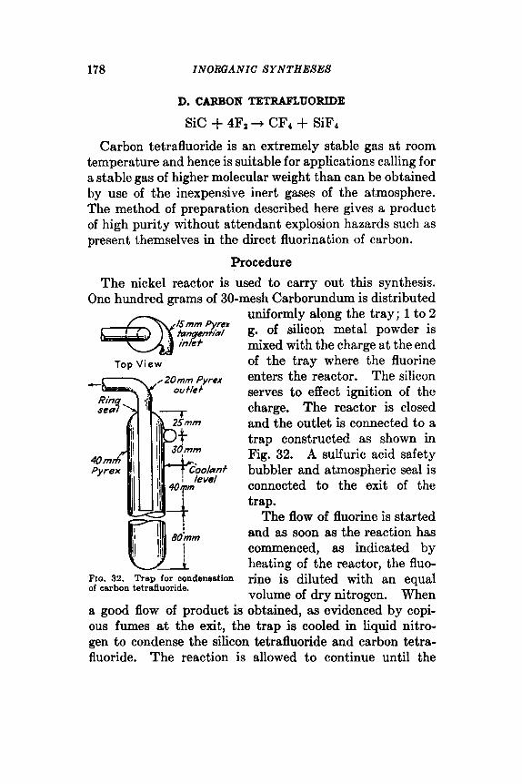
178 INORQANIC SYNTHESES
D. CARBON TETRAFLUORIDE
Sic + 4Fz + CF4 + SiFl
Carbon tetrafluoride is an extremely stable gas at room temperature and hence is suitable for applications calling for a stable gas of higher molecular weight than can be obtained by use of the inexpensive inert gases of the atmosphere. The method of preparation described here gives a product of high purity without attendant explosion hazards such as present themselves in the direct fluorination of carbon.
Procedure
The nickel reactor is used to carry out this synthesis. One hundred grams of 30-mesh Carborundum is distributed
Top V iew ,/2Omm Pyrex
ou fle +
e i FIG. 32. Trap for condeneation of carbon tetrduoride.
uniformly along the tray; 1 to 2 g. of silicon metal powder is mixed with the charge at the end of the tray where the fluorine enters the reactor. The silicon serves to effect ignition of the charge. The reactor is closed and the outlet is connected to a trap constructed as shown in Fig. 32. A sulfuric acid safety bubbler and atmospheric seal is connected to the exit of the trap.
The flow of fluorine is started and as soon as the reaction has commenced, as indicated by heating of the reactor, the fluo- rine is diluted with an equal volume of dry nitrogen. When
a good flow of product is obtained, as evidenced by copi- ous fumes at the exit, the trap is cooled in liquid nitro- gen to condense the silicon tetrafluoride and carbon tetra- fluoride. The reaction is allowed to continue until the
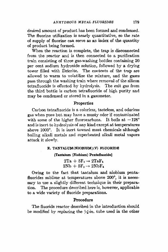
ANHYDROUS METAL FLUORIDES 179
desired amount of product has been formed and condensed. The fluorine utilization is nearly quantitative, so the rate of supply of fluorine can serve as an index of the quantity of product being formed.
When the reaction is complete, the trap is disconnected from the reactor and is then connected to a purification train consisting of three gas-washing bottles containing 20 per cent sodium hydroxide solution, followed by a drying tower filled with Drierite. The contents of the trap are allowed to warm to volatilize the mixture, and the gases pass through the washing train where removal of the silicon tetrafluoride is effected by hydrolysis. The exit gas from the third bottle is carbon tetrafluoride of high purity and may be condensed or stored in a gasometer.
Properties
Carbon tetrafluoride is a colorless, tasteless, and odorless gas when pure but may have a musty odor if contaminated with some of the higher fluorocarbons. It boils a t -128" and is inert to hydrolysis of any kind except a t temperatures above 1000". It is inert toward most chemicals although boiling alkali metals and superheated alkali metal vapors attack it slowly.
E. TANTALUM(NI0BIUM) (V) FLUORIDE
[Tantalum (Niobium) Pentafiuoride]
2Ta + 5F2+ 2TaFa 2Nb + 5F2+ 2NbFa
Owing to the fact that tantalum and niobium penta- fluorides sublime at temperatures above 200", it is neces- sary to use a slightly different technique in their prepara- tion. The procedure described here is, however, applicable to a wide variety of fluoride preparations.
Procedure The fluoride reactor described in the introduction should
be modified by replacing the &in. tube used in the other

180 INORGANIC SYNTHESES
preparations with a >$in. Monel tube at the exit. A trap
Top V i e w
Bronze sfowocks
Fxo. 33. Metal trap for condensation of tnntslurn- (niobium) (V) fluoride.
is constructed as shown in Fig. 33 and the apparatus is assembled as shown in Fig. 34. The heating wire is asbestos-cover ed N i c h r ome , wound so that the region from the exit of the reactor to the chamber of the trap can be maintained at 300".
The tray is charged with 50.g. of tantalum or niobium powder and the flow of fluorine is started. It may be necessary to raise the tem- perature of the furnace as high as 300" to initiate the reaction, but that is normally unnecessary. The line heater should be placed in oper- ation to prevent clogging of the line. The trap is cooled to within 1 in. of thc inlet tube with ice and water. The reaction is continued
until fluorine is detected at the exit, after which the flow of fluorine is stopped and the valves on the trap closed.
fluorine /n
TO&
Fig. 34. (niobium) (V) fluoride.
Apparatua assembly for preparation and purification oi tantalum-
It is desirable, although not essential, to purge the system first with dry nitrogen.

ANHYDROUS METAL FLUORIDES 181
The trap is frozen in Dry Ice-trichloroethylcne slush and pumped free of noncondensables by means of a Hyvac pump, after which the tantalum(V) fluoride [or nio- bium(V) fluoride] may be readily sublimed into the reactor or container where it is to be used.
Properties
Niobium(V) fluoridelO*ll and tantalum(V) f l u ~ r i d e ~ ~ ~ ' ~ are white, crystalline solids, both of which boil at 229" and melt at 75" and 97' respectively. They form a eutectic mixture that is liquid at room temperature. Both com- pounds must be handled under anhydrous conditions since they are hygroscopic and fume in moist air. Nio- bium(V) fluoride and tantalum(V) fluoride have specific gravities of 3.29 and 4.74 respectively.
F. TUNGSTEN (VI) FLUORIDE
(Tungsten Heduoride)
w 4- 3F2+ WFs
Tungsten(V1) fluoride, with a molecular weight of 297.92, is one of the heaviest gases known and as such would be expected to have some interesting uses. Its reactive character may detract from possible applications, but where this property would not interfere the compound could be used. It was prepared and characterized by Ruff and his coworkers, who used the hexachloride as a starting material.' The method of direct synthesis used in the fol- lowing procedure has proved to be very satisfactory and simple. l4
Procedure
The nickel reactor already described (Fig. 30) and two traps, constructed as shown in Fig. 35, are needed for this preparation.
Fifty grams of tungsten metal powder is placed in the reactor tray in as thin a layer as possible. The tray is
The complete setup is shown in Fig. 36.
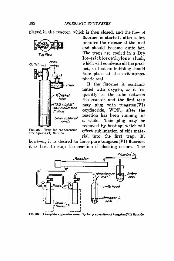
182 IN OROA N I C SYNTHESES
placed in the reactor, which is then closed, and the flow of
Top View
FIG. 36. Trap for condensation of tungaten(V1) fluoride.
however, it is desired to
fluorine is started; after a few minutes the reactor at the inlet end should become quite hot. The traps are cooled in a Dry Icetrichloroethylene slush, which will condense all the prod- uct, so that no bubbling should take place at the exit atmos- pheric seal.
If the fluorine is contami- nated with oxygen, as it fre- quently is, the tube between the reactor and the first trap may plug with tungsten(V1) oxyfluoride, WOF4, after the reaction has been running for a while. This plug may be removed by heating, which will effect sublimation of this mate- rial into the first trap. If,
have pure tungsten(V1) fluoride, it is best to stop the reaction if blocking occurs. The
L---J FIO. 30. Complete apparatus assembly for preparation of tungsten(V1) fluoride.
ANHYDROUS METAL FLUORIDES 183
valves on the traps should then be closed and the traps disconnected. If blocking does not occur, the reaction is continued until the presence of fluorine is detected at the exit of the atmospheric seal, which indicates that all of the tungsten has undergone reaction. The fluorine flow should be stopped, the valves on the traps should be closed, and the traps disconnected.
The traps are frozen in a Dry Ice-trichloroethylene slush and evacuated with a Hyvac pump to remove the fluorine present. The product may be distilled from one container to another through evacuated lines. The traps serve admirably as storage cylinders for the material.
Properties
Tungsten(V1) fluoride is a colorless gas that condenses to a colorless liquid at 19.5” and freezes to a crystalline white solid at 2.5”. It fumes in moist air and must be handled under anhydrous conditions. The specific gravity of the liquid is 3.441 a t 15’. It may be handled in carefully out- gassed glass systems provided that greases, mercury, and organic materials, as well as water, are absent from the system.
References
1. SIMONS: INORGANIC SYNTHESES, 1, 138 (1939). 2. CADY: W., 1, 142 (1939). 3. Harshaw Chemical Company, Cleveland, Ohio. 4. Pennsylvania Salt Company, Philadelphia, Pa. 5. FOWLER and BURFORD: “Fluorocarbons,” O.T.S. Report, Department
of Commerce, Washington, D.C., 1947. 6. RUFF and ASCHER: Z. anorq. allgem. Chem., 189, 195 (1929). 7. RUFF, EUNER, and HELLER: z 7 d , 62,256 (1907). 8. POULENC: Compt. rend., 114, 746, 1426 (1892). 9. RUFF and GIESE: Ber., 69B, 598 (1936).
10. MOISSAN: Compt. rend., 66, 180 (1868). 11. RUFF and ZEDNER: Ber., 4!2,492 (1909). 12. MOISSAN: Bull. uoc. chim., (31 27,434 (1902). 13. RUFF and SCHILLER: 2. a w g . Chem., 72,355 (1911). 14. PEIEST and S c a u r ~ ~ : J . Am. C h . Soc., 76,3378 (1948).

184 INORGANIC SYNTHESES
48. BROMINE(III) FLUORIDE
(Bromine Trifluoride)
Br2 + 3F2+ 2BrF3
SUBMITTED BY J. H. SIMONS* CIiEXKED BY DON M. YOST? AND M. T. ROGERSf
The interhalogen compound bromine(II1) fluoride has been prepared by (1) uniting a stream of gaseous fluorine
with one of nitrogen-containing bromine vapor, and (2) bubbling fluorine through liquid bromine in a copper container. The latter procedure is preferred, since it is more readily controlled and makes possible production of bromine(II1) fluoride in any desired quantity.
Procedure
The copper tubes A are silver-soldered to the copper cover disk C. To facilitate distilla- tion of the product, these copper tubes should be silver-soldered at the outer ends to 7/25 copper tapers. Graphite is used as a lubricant. B is a brass cap which is
tus for the prepa- drilled out to accommodate the copper tubes and which screws onto the copper vessel E. D is a fuse wire, Teflon, or
similar gasket. The bottom of the copper reactor at G is welded to the walls of the copper container, since bromine trifluoride reacts readily with ordinary solders and brazing alloys.
Fluorine is prepared electrolytically either by the high- temperature process2 or by electrolysis of KF-2HF at 100°.3 It is freed from hydrogen fluoride by passage through a tube
-+
The apparatus is shown in Fig. 37.
Fro. 37. Appara-
ration of bromine (111) fluoride.
* Pennsylvania State College, State College, Pa. t California Institute of Technology, Pasadena, Calif.
Inorganic Syntheses, Volume 111 Edited by Ludwig F. Audrieth
Copyright © 1950 by McGraw-Hill Book Company, Inc.

B R O M I N E ( I I I ) FLUORIDE 185
containing sodium fluoride or potassium fluorids at loo", and then through a Dry Ice trap. The purified gas is bubbled through bromine in the copper vessel until fluorine escapes in quantity from the exit tube. The product may be retained in the reaction vessel by replacing C with a copper disk to close the vessel. Preferably, the bro- mine(II1) fluoride is distilled from the reaction vessel at 1-cm. pressure into a platinum trap or a thoroughly dry and clean steel cylinder.*
Properties Bromine(II1) fluoride is an extremely reactive, straw-
colored liquid at room temperature. It reacts rapidly with glass and most siliceous materials. The reac:tion with quartz is noticeable at 30". It will set fire to materials like wood and paper. It reacts violently with water and with many organic substances. A small quantity frozen at -80", when dropped into liquid toluene at the same temperature, reacts with great violence.
Bromine(II1) fluoride melts at 8.801 and boils at 127 k The critical temperature is about 327O.l The density of the solid at the melting point is 3.23 g./ml.; of the liquid, 2.843 g./ml.' The density of the liquid at any temperature can be calculated from the equation: d = 3.623 -0.00277T.' The vapor pressure of the liquid follows the
2220.2 equation: log p = 8.41954 7- The heat of vaporiza-
tion is about 10 kcal.6 Calculations have given a value of 25.3 for Trouton's constants6
References
1. RUFF and BRAIDA: 2. a m g . allgem. Chem., 206,63 (1932). 2. SIbfONS: INORQANIC SYNTHESES, 1, 138 (1939).
* Other fluorides of bromine may be present as impurities: RrF, boiling at about 20", and BrF6, boiling a t 40.5". Since theso arc more volatile than the trifluoride, they are readily removed by distillation. If the fluorine is allowed to pass through the reaction mixture until the excess escapes from the exit tube, only negligible amounts of RrF will be present. As RrF66 is formed in quantity only a t 200", it will be present in relatively small amounts.

186 INORGANIC SYNTHESES
3. SCHUMB, YOUNG, and RADIMER: lnd. Eng. Chem., 89,243 (1947). 4. RUFF and BRAIDA: 2. anmg. allgem. Chem., 214,Sl (1933). 6. RUFF and MENZEL: ibid., 202,49 (1931). 6. RUBF and BRAIDA: ibid., 214,91 (1933).
49. RHENIUM(VI) OXIDE
(Rhenium Trioxide)
Rhenium(V1) oxide can be prepared by the incomplete combustion of rhenium in oxygen, but the reaction is hard to control. It can also be obtained by the reduction of rhenium(VI1) oxide (1) with rhenium at elevated tempera- tures' and (2) with rhenium(1V) oxide2 at 300'. These procedures are unsatisfactory, as difficulty is experienced in removing unreacted rhenium or rhenium(VI1) oxide. Simpler procedures that lead directly to pure products involve reducing rhenium(VI1) oxide with either dioxane or carbon monoxide.
Procedure A
Re207 + xCJh02 -+ Re&(CJLO2), Re2O,-(C4H8O2), ___f ReOa + decomposition product
125-14bO
SUBMITTED BY H. NECHAMKIN+ AND C. F. HISKEY* CHECKED BY THEBALD M O E L L E R t AND c. E. SHOEMAKERt
The reaction tube containing approximately 1 g. of rhenium(VI1) oxide (synthesis 50) is detached from the apparatus. Four milliliters of anhydrous dioxane, dried by distillation from sodium metal, is poured over the sample, the operation being performed rapidly to reduce moisture pickup. The reaction tube is then warmed gently to dissolve the oxide to a colorless solution. Localized heating is to be avoided because it gives colored solutions and impure products. The clear solution is placed in an ice bath and frozen. The frozen mass is allowed to warm to room temperature, the rhenium(VI1) oxiddoxane complex crystallizing out as a dense, pearl- gray deposit as the excess dioxane melts. The freezing
* Polytechnic Institute of Brooklyn, Brooklyn, N.Y. t University of Illinois, Urbana, IlI.
R H E N I U M ( V I ) O X I D E 187
and melting are repeated at least once to ensure separation of the complex. The colorless supernatant liquid contain- ing only negligible amounts of rhenium is then removed by decantation. The complex is dried at room temperature over sulfuric acid in a vacuum desiccator.
The dry complex is transferred quickly to a crucible which is heated gently on a hot plate. The material is first melted to a colorless to blue-green liquid which decom- poses to red rhenium(V1) oxide and volatile rhenium-free products as heating is continued. Reaction is complete in a few minutes. The product is chemically pure. The yield amounts to about 95 per cent of theory, some loss occur- ring because of the slight solubility of the complex in dioxane.
Procedure B Rez07 + CO + 2Re03 + CO,
SUBMITTED BY A. D. MELAVEN, * J. N. FOWLE, * W. BRICKELL,. AND C. F. HISKEY
CHECKED BY THERALD MOELLERt AND R. L. B U R T O N t
The apparatus for the preparation of rhenium(VI1) oxide (synthesis 50) is modified by interposing a short (2- to 3-mm.) section of 1-mm. capillary tubing between the reac- tion tube and the remainder of the apparatus as depicted in Fig. 39. One-tenth to one gram of rhenium metal is converted into rhenium(VI1) oxide, which is purified by sublimation. Any nonvolatile residue remaining in the tip of the reaction tube is sealed off and detached. The reaction tube is bent from a horizontal to a vertical position as indicated in Fig. 38. The system is evacuated rand filled with carbon monoxide* to a pressure of one atmosphere. The tube containing the rhenium(VI1) oxide is slowly heated to 175" by means of a glycerol bath and is main- tained at that temperature until the oxide is blue. The temperature is then raised slowly to 225O, and, after the preparation has turned red, is increased to 280". The
* University of Tennessee, Knoxville, Tenn. t University of Illinois, Urbans, IlL

188 I N O RG A N I C SYNTHESES
Position for rhenium combustion
entire heating operation should last no more than 2 to 3 hours. The red product is pure Re08. Yield, quantitative.
Position for carbon monoxide reduction
v
Properties Rhenium(V1) oxide is a red solid, crystallizing in the
cubic system. In thin layers, the oxide appears green by transmitted light. It is unreactive to water and to most reagents of nonoxidizing or reducing character. At 400°, it disproportionates in a vacuum to rhenium(1V) and rhe- nium(VI1) oxides.
References
1. RILTZ, LEHRER, and MEISEL: 2. anofg. allgem. Chent., 207, 113 (1932). 2. BILTZ and hsiRER: 2. anorg. allgem. Chem., 214, 225 (1033). 3. GILLILASD and B L ~ S C H ~ R D : IKORGAXIC SYh.THE:SES, 2, 81 (1946).
60. RHENlUM(VII) OXIDE
(Dirhenium Heptoxide)
4Re + 702+ 2Re207 SUBMITTED BY A . D. MELAVEN,* J. N. FOWLE,* WALTER BRICKELL,' AND
C. F. HISKEY* C H E C K E D BY T H E R A L D h f 0 E L L E R t A N D R. L. BURTONt
Rhenium(VI1) oxide can be prepared from the metal or from lower rhenium oxides by direct oxidation in a stream of air or oxygen.'O2 When this is done, however, a variable
* University of Tennessee, Knoxville, Tenn. t University of Illinois, Urbana. Ill.

R H E N I U M ( V I I ) O X I D E 189
amount of an uncondensable oxide of undetermined com- position is produced as a white smoke along with the yellow oxide. By means of controlled oxidation in a closed system such difficulties may be avoided, and the preparation of small quantities of rhenium(VI1) oxide effected easily.
Oxidation of the metal appears t.0 proceed in two steps. The metal first ignites with a red glow.. When this reaction subsides, a deposit of red rhenium(V1) oxide remains. Further oxidation as heating is continued then gives t,he volatile yellow rhenium(VI1) oxide.
Procedure
Cp to 2 g. of rhenium metal3 is placed a t the closed end of
Ba//ast bU/b
jr, v a c u u m - 6 70 oxygen - 0-
mefal funk x
FIO. 39. Apparatus for preparation of rhenium(VI1) oxide.
a pyrex tube 9 mm. in diameter and 20 cni. or more in length. This tube is then sealed in a horizontal position to an assembly of a t least 1-1. capacity as shown in Fig. 39. A ballast bulb and a three-way stopcock are essential to the assembly. A closed-end manometer sealed to the appa- ratus is of convenience, particularly when larger amounts of rhenium are to be oxidized. The apparatus is evacuated and flamed to ensure complete dryness. It is then flushed with dry oxygen and filled with this gas to a pressure of 1 atmosphere. A short tubular furnace, previously heated to 400 to 425", is slipped over the horizontal tube containing the rhenium so as to heat a 5-cm. length. After 2 hours of heating, the furnace is advanced another 5 cm. and heating

190 INORGANIC SYNTHESES
is continued for an additional 2 hours. If the product in the tube is not bright yellow, heating is continued as long as is necessary.* After the reaction is complete, the sub-. limed sample is preserved by sealing it off in the reaction tube. By this method it is possible to form the oxide and deposit
it wherever desired in a particular apparatus. It is impor- tant to work with the combustion tube in a horizontal posi- tion. In a vertical position the reaction time is lengthened immeasurably.
Proper ties
Rhenium(VI1) oxide is a canary-yellow solid, forming as hexagonal crystals. It begins to sublime at 250" under 1 atmosphere of pressure and melts at 297" in a closed tube.6 It is very soluble in water and in such basic solvents as ethers, esters, alcohols, dioxane, and pyridine. It is extremely deliquescent, absorbing water to form perrhenic acid (HRe04). The product may be analyzed using the tetraphenylarsonium chloride pr~cedure .~
References 1. NODDACK and NODDACK: Naturwissenschaften, 17, 93 (1929); 2. anorp.
2. BRISCOE, ROBINSON, and RUDGE: Nature, 120, 618 (1932). 3. HURD and BRIMM: INORGANIC SYNTHESES, 1, 175 (1939). 4. WILLARD and SMITH: Anal. Chem., 11,305 (1939). 5. OGAWA: BuU. Chem. SOC. Japan, 7,265 (1932).
allgem. Chem., 181, 1 (1929); 216, 129 (1933).
* Not more than 5 hours of heating should be required for 2 g. of the metal.

CHAPTER VIII
See also: Nickel(I1) fluoride, synthesis 47A Cobalt(II1) flouride, synthesis 47B
61. ANHYDROUS IRON(I3I) CHLORIDE
(Ferric Chloride)
2Fe + 3C1, + 2FeCL SUBMITTED BY BETTY RAPP TARR* CHECKED BY HAROLD s. BOOTHt AND ALBERT D O L A N C E t
The most convenient laboratory method for the prepara- tion of iron(II1) chloride involves the direct combustion of metallic iron in dry chlorine.' The directions given here are suitable for preparing this material in 100-g. quantities or, by simple modification of the apparatus, in larger amounts.
Iron(II1) chloride has been employed as a catalyst in such reactions as the Friedel-Crafts synthesis,2 the prepara- tion of alkyl chlorides from olefins (other than ethylene), and the hydrogenation3 and chlorination of aromatic compounds.
Procedure A (Small Quantities) The apparatus depicted in Fig. 40 is made of 28-mm.
Pyrex tubing and consists of a reaction chamber D and three collection chambers E, F, and G, each 25 cm. in length joined by 5-cm. constricted segments that should not be less than 10 mm. in diameter. Just before the reac- tion is carried out the tube is flamed, while a current of dry air is passed through it, to remove all moisture.
* University of Illinois, Urbana, Ill. t Wetitern Reserve University, Cleveland, Ohio.
191
Inorganic Syntheses, Volume 111 Edited by Ludwig F. Audrieth
Copyright © 1950 by McGraw-Hill Book Company, Inc.

192 INORGANIC SYNTHESES
Thirty-five and one-half grams of pure iron wire (No. 36)* is dried at llOo, cooled in a desiccator and then placed in the reaction chamber D. Chlorine gas is passed through the sulfuric acid wash bottle A and through a drying tube C containing phosphorus(V) oxide. Between these two vessels, the train is provided with a side tube B dipping into sulfuric acid to act as a safety outlet for the chlorine in event the combustion tube becomes clogged. From C the chlorine is passed through the combust,ion tube and thence through a container of calcium chloride H to prevent the entrance of moisture. The unreacted chlorine passes through a trap I and is absorbed by sodium hydroxide in J .
S m I I
- RQ. 40. Apparatus for preparation of anhydroua iron(II1) chloride.
After the air has been displaced with chlorine, the seg- ment D containing the iron wire is heated gently. The reaction takes place readily and iron(II1) chloride soon begins to fill the reaction chamber. After the reaction has ceased, the product is sublimed by careful heating in an atmosphere of chlorine from the reaction chamber into the two succeeding segments E and F . Care is taken that none of the constricted portions become clogged. The flow of chlorine is stopped and the tube sealed off at the point m. The opposite end of the tube at p is now attached to the vacuum line through a sodium hydroxide trap and the excess of chlorine is removed. The tube is then sealed at p . The anhydrous chloride is then distributed by sublimation into the tubes as desired. If it is desired to collect the total yield in one compartment, the end segments may be
vigorous. *Finer wire should not be used, aa the reaction is apt to become too
ANHYDROUS ZRON(ZZZ) CHLORIDE 193
heated in an electric tube furnace and each one may be sealed off after it has been emptied.
The yield is nearly quantitative. Since it is difficult to sublime the last bit of iron(II1) chloride completely from the 'reaction chamber, there is usually about a 3 per cent loss at this point. The material is not absolutely pure, as it contains small amounts of iron(I1) chloride, but is suit- able for most work. An absolutely pure product may be obtained by repeated sublimation in an atmosphere of chlorine.
Procedure B (Larger Quantities)
That portion of the apparatus from s to p is replaced by a pyrex combustion tube K connected through a rubber stopper to a wide-mouthed bottle L (which, after removal from the apparatus, can be closed with a ground-glass stopper). This bottle should be thoroughly dried in an oven at 125" before the synthesis is carried out. The reac- tion tube K is flamed while dry air is passed through it. For 70 g. of iron wire, a 1-1. bottle should be used. Number 36 iron wire is employed, as before. The iron(II1) chloride, as it is formed, is sublimed into the bottle.
The excess chlorine is conducted to trap H through a tube that should be at least 1 cm. in diameter. When the reac- tion is complete, the bottle L is disconnected from the apparatus and immediately stoppered.
Properties
Anhydrous iron(II1) chloride forms crystals that are dark green in reflected light and purple-red in transmitted light. The compound melts at 306" and can be volatilized at a slightly lower temperature. Vapor density measure- ments show that iron(II1) chloride is dimeric at 440", but monomeric above 750". Measurements at these higher temperatures are complicated by the fact that appreciable dissociation into iron(I1) chloride and chlorine also takes place. On exposure to air the anhydrous salt is readily transformed to the yellow-brown 6-hydrate. Accordingly,
194 INORGANIC SYNTHESES
if it is necessary to transfer the anhydrous material from one vessel to another, the operation should be carried out in a "dry box," or according to the procedure described by Bergstrom.'
Anhydrous iron(II1) chloride is soluble in many solvents, especially those which can coordinate with it, such as the alcohols, ethers, ketones, pyridine, benzonitrile, phos- phorus( 111) bromide, sulfur dioxide, and sulfuryl chloride.
References
1. BERGSTROX: J . Am. Chem. SOC., 46, 1547 (1924). 2. GALLAY and WAITBY: Can. J . Research, 2 , 31 (1930). 3. KLING and FLORENTIN: Compt. rend., 184,822 (1927). 4. MASON, SMALE, THOMPSON, and WHEELER: J . Chem. Soc., 1931, 3150.
62. HEXAMMINENICKEL(II) BROMIDE AND
HEXAMMnVENICKEL(II) IODIDE
[Ni(OH)2]4-H20 + 8HX + 4NiX2 + 9H20 KiX2 + 6NH3 3 [Ni(NHJG]X2
SLTSMXTTED BY GEORGE W. WATT' CHECKED BY R. KEITII OSTERHELDf
The hexammines of the bromide and iodide of nickel(I1) provide a convenient means of introducing nickel(I1) ion into liquid ammonia solutions under anhydrous condi- tions.'S2 Although the literature includes numerous refer- ences to the preparation of these compounds from the corresponding anhydrous salts or their details of procedure have not been specified. The simple pro- cedure outlined below provides these salts in high yield and high purity.
Procedure Twenty grams of reagent-grade hydrated nickel(I1)
hydroxide,S [Ni(OH)2]4-Hz0, is dissolved in 55 ml. of warm * The University of Texas, Austin, Tex. t The University of Illinois, Urbana, Ill. $If the solid hydroxide is not available, i t may be prepared conven-
iently by precipitation from a solution of a nickel(I1) salt such aa the sulfate by addition of sodium hydroxide, followed by thorough washing.

H E X A M M I N E N I C K E L ( I I ) BROMIDE 195
constant-boiling hydrobromic acid solution (b.p. 126" ; d. 1.47; 47.5 per cent HBr).* If any unreacted solid remains, it is removed by filtration. To the filtrate is added an additional 3 ml. of hydrobromic acid solution and enough water to bring the total volume to 150 ml. This solution is added dropwise over a period of 20 to 25 minutes to 550 ml. of concentrated aqueous ammonia solution pre- viously heated to 65 to 70". The solution is maintained a t this temperature throughout the addition of the nickel(I1) bromide solution ; stirring and saturation with respect to ammonia are accomplished by bubbling through the solu- tion a vigorous stream of ammonia gas from a commer- cial cylinder. Pale violet-colored crystals of hexammine- nickel(I1) bromide begin to separate from the solution before the addition of the bromide solution is complete.
Crystallization is completed by cooling the reaction mix- ture in an ice bath. The yield may be increased slightly by continuing the addition of ammonia gas until the solu- tion. is saturated at the lower temperature. The crystals are removed by filtration, washed five times with 50-ml. portions of cold 26 per cent aqueous ammonia. Yield, 63 g. or 95 per cent. Anal. Calcd. for Ni(NH3)6Brz: Ni, 18.30; Br, 49.84; NH3, 31.86. Found: Ni, 18.28; Br, 49.67; NH3, 31.90. Calcd. for Ki(KH3)612: Ni, 14.15; I, 61.25; NH3, 24.64. Found: Ni, 14.11; I, 61.58; NH3, 23.94.
Properties The hexamminenickel(I1) bromide and iodide separate in
the form of face-centered cubic crystals that are isomor- phous with ammonium hexachloroplatinate(1V). Depend- ing upon particle size, the color of the crystals varies from pale lavender to deep blue. The bromide is soluble in hot water and may be recrystallized from concentrated aqueous ammonia. These salts should be stored in tightly stop-
* Although freshly distilled constantrboiling acid is recommended, ita concentration is not critical. Thus, the bromide has been prepared satis- factorily using 68.8 ml. of 40 per cent hydrobromic acid (d. 1.38). Simi- larly, the iodide has been formed using 87 ml. of 47 per cent hydriodic acid (d. 1.50).

196 INORGANIC SYNTHESES
pered bottles to minimize atmospheric oxidation. The iodide is considerably less soluble in water than the bromide and both are sparingly soluble in liquid ammonia. Both salts are decomposed by bases and are converted to nickel(I1) hydroxide by boiling with water. Thermal dis- sociation of the hexamminenickel(I1) bromide yields suc- cessively compounds containing 2, 1, 0 mols of ammonia. The corresponding iodide is less stable and loses ammonia to form the diammine, and finally the unsolvated iodide.
References
1. BURGESS and EASTES: J . Am. Chem. SOC., 63, 2674 (1941). 2. WATT and DAVIES: ibid., 70, 3753 (1948). 3. RICHARDS and CUSHMAN: 2. czn.org. Chem., 16, 167 (1898). 4. RAMMELSBERG: Pogg. Ann., 48, 119, 155 (1839); 66,243 (1846). 5. ERDMAN: J . prczkt. Chem., (11 1,266 (1834); [ l ] 7, 249 (1836).
63. BIS (N,N’ -DISALICYLALETHnENEDIAMINE) -p- AQUODICOBALT (11)
(Bis[N,N’-bis (0-hydroxybenzylidine)ethylenediamine] -p - aquodicobalt (II) }
YHO 2 0 - - - - O H + C2H4(NH~)2 +
Hz Hz c-c
H / \ H N=C
HO- + 2H20 / C=N
=-OH (C ISHISNZO~)
2CISH1,N2O2 + 2CoC1, + 4NaOH + {[CO(CI,H,,N~O~)],H,O~ + 4NaC1 + 3H20
SUBMIWED BY HARVEY DIEHL* AND CLIFFORD C. HACH’ CHECKED BY JOHN c. BAILAR, JR.t
Iowa State College, Ames, Iowa. t University of Illinois, Urbana, Ill.

BIS(N,N'-DISALICYLALETHYLBNEDIAMINE) 197
The cobalt (11) derivative of N,N'-disalicylalethylene- diamine, a Schiff base prepared from salicylaldehyde and ethylenediamine, was first described by Pfeiffer, Breith, Lubbe, and Tsumaki' and further studied by Tsumaki.2 It was later investigated intensively by Diehl and cowork- ers,3 who showed that it is a binuclear compound in which a molecule of water acts as a bridging group (p-aquo) between two cobalt atoms, each of which is surrounded by the quadridentate, chelating molecule of the Sch8 base. This material has the unique property of reversibly absorb- ing and releasing oxygen. The addition of the oxygen is thought to take place by the formation of a peroxo group, which makes a second bridge between the two cobalt atoms and fills the sixth coordination position of each cobalt atom. Thus, one oxygen molecule is absorbed for each two cobalt atoms, corresponding to a gain in weight of 4.79 per cent.
The compound was originally prepared by bringing cobalt acetate, ethylenediamine, and salicylaldehyde together simultaneously in an aqueous-alcohol reaction medium. Unless care is exercised in this procedure the product is relatively impure, but if all the factors mentioned below are controlled, a satisfactory material can be obtained by this direct mixing method. A much better procedure involves the preliminary formation of the Schiff base and its subsequent reaction with a cobalt salt. In this manner a product is obtained containing the correct stoichiometric ratio of salicylaldehyde to ethylcnediamine ; slight depar- ture from the equivalent quantities or inadequate stirring in the direct mixing method leads to contamination of the product by the cobalt derivative of salicylaldehyde, by cobalt-ethylenediamine compounds, or by the S c M base.
The recommended synthesis is complicated under certain conditions by the formation of three by-products, olive, black, and red in color, all of which are inactive toward oxygen. The olive by-product is formed on prolonged contact of the oxygen-carrying material with hot water,
198 INORGANIC SYNTHESES
either during the formation of the material or during drying. The presence of any free acid, especially when hot, promotes the formation of this olive by-product. A critical point in the procedure is, therefore, the drying step, which must be carried out as rapidly as possible.
The black by-product is formed from the oxygen-carrying compound by contact with oxygen, especially in the pres- ence of alcohol; its formation is not observed in the pro- cedure given here. It is soluble in water and removed by washing. The red by-product results from the action of alkali on the oxygen-carrying compound. In the procedure given below, a slight deficiency of alkali is used to avoid its formation. It is isomeric with the oxygen-carrying com- pound, but inactive toward oxygen.
Procedure N~-Disalicylalethylenedi~e. The salicylaldehyde is
purified by the process of shaking or by standing in contact with powdered calcium carbonate, followed by distillation. To a solution of 244 g. (2 mols) of the purified material in 1 1. of boiling 95 per cent ethyl alcohol is added 60.1 g. (1 mol) of ethylenediamine; this is measured by weighing out the appropriate amount of aqueous solution. If the concentration of the ethylenediamine is not known within a few per cent, a sample should be titrated against a stand- ard acid, using methyl red as indicator. In 20 to 30 seconds the mass becomes solid with formation of a bright yellow, crystalline material. The reaction mixture is cooled and filtered on a Buchner funnel, and the precipitate is spread in thin layers on absorbent paper to dry. It may be recrystallized from 6 1. of hot 95 per cent alcohol or used without further purification. It will dissolve somewhat more readily in the next step if it is not allowed to dry completely. Yield, 255 g. (95 per cent). The compound melts at 123’.
Bis (N,N’ -disalicylalethylenediamine) -p-aquodicobalt. One mol (268 g.) of finely ground disalicylalethylened-
B.?SS(N,N'-DISALICYLALETH YLENEDIAMINE) 199
amine, 79.5 g. (2 mols less 0.5 g.) of sodium hydroxide and 5 g. of sodium acetate, NaC2HsO2.3H20, are dissolved in 3 1. of boiling water. Solution of the disalicylalethylene- diamine requires from 10 to 20 minutes and depends on the state of subdivision of the material and the agitation given the mixture. Stirring is continued subsequently while a solution of 238 g. (1 mol) of hexahydrated cobalt(I1) chloride (CoCl2.6H20) in 500 ml. of hot water is added, until the mixture sets up to a reddish-brown paste. The mass,is covered with 34 in. of water and allowed to stand for at least 15 minutes. It is then centrifuged* until most of the mother liquor has been removed and a hard cake remains. Three portions of water (each about 250 ml.) are added, the liquid being removed by centrifugation after each addition. The cake is removed from the centrifuge basket and mixed thoroughly with 1.5 1. of water so that no large particles remain and a uniform slurry is obtained. It is centrifuged again, and is finally washed with a few hundred milliliters of, water. The filtrate will never be colorless, but will be light brown. The cake is finally centrifuged as dry as possible. If a letter press? is avail- able, the cake should be wrapped in a few thicknesses of towel and pressed. It is then broken into small pieces and dried at 100" in a good vacuum. The final vacuum drying apparatus need not be complicated but should be provided with a large gas outlet and a condenser to allow adequate facility for the escape of steam. Direct connection to a water pump is poor inasmuch as a water pump cannot handle a sufficiently large volume of vapor. A satisfactory drier may be constructed from pyrex tubing, 2 in. in diam-
If a centrifuge is not available, suction filtration may be substituted. However, the residual water left on the cake is lesa when a material is centri- fuged than when filtered by suction, 80 the use of a centrifuge is much to be preferred. The centrifuge of the International Equipment Company, No, 418, with a bronze basket is ideal for the purpose.
t The use of a hydraulic press is desirable if the material hrts been sepa- rated by centrifuging and almost neceseary if it is separated by suction filtration.

200 INORGANIC SYNTHESES
eter and 36 in. long. This tube is surrounded by a second pyrex tube 3 in. in diameter and just slightly shorter, which serves as a jacket through which steam can be passed. The inner tube can be supported concentrically in the outer tube at one end by a few turns of rubber tubing of suitable diameter, which also serves as a steam inlet. At the other end, a single turn of rubber tubing can be used, leaving a gap at the bottom for the condensate to escape. The material is placed in the inner tube on a tray made by bending a strip of tin plate into a semicircular cross section. One end of this tube is stoppered and the other connected through a tube 0.75 in. in diameter to a condenser, receiver, and water pump. The condenser and receiver may consist simply of a 1-1. round-bottomed flask cooled by a stream of running water. The yield is 300 g., or 90 per cent; oxygen- carrying capacity, 4.7 to 4.8 per cent; theoretical capacity, 4.79 per cent.*
Properties
Bis(N,N'-disalicylalethylenediamine)-p-aquodicobalt is a maroon-colored, microcrystalline material, which is some- what soluble in pyridine, chloroform, and benzene. It crystallizes from pyridine and chloroform with solvent of crystallization that can be removed by heating a t 120" in a vacuum; the resulting product, however, is of low oxygen- carrying capacity. The material absorbs oxygen in the dry state, turning from maroon to black in color. The rate of oxygenation of the material is greatly affected by pressure and temperature, being a maximum with respect to tem-
The oxygen-carrying capacity of the material is determined by exposing a weighed sample on a boat to oxygen or air at increased pressure and obtain- ing the increase in weight. This is best carried out in a metal tubeequipped with a screw cap, prewure gage, line to oxygen tank or air line, and release valve. A period of 10 minutes in oxygen a t 100 pounds pressure is sufficient to saturate the compound, after which the pressure may be released and the boat weighed rapidly. It is usually necessary to deoxygenate the material at 100' in a vacuum to secure a correct initial weight of the sample. The maximum oxygen-carrying capacity is obtained after two or three cycles of oxygenation and deoxygenation.

B IS ( N , N'- D IS A I, I C YL A L E T H YL E N E D I A M I N E ) ' 20 1
perature at about 20". The oxygen is expelled by heating the material to 65". It also absorbs nitrogen(I1) oxide and nitrogen(1V) oxide, but irreversibly. It does not absorb carbon monoxide, nitrous oxide, or sulfur dioxide. The deoxygenated form of the material is paramagnetic, the oxygenated form diamagnetic. It catalyzes the lumi- nescence of 3-aminophthalhydrazide (luminol) in alkaline solution containing hydrogen peroxide. The compound is quite toxic; inhalation of the finely divided dust should be avoided.
References 1. PFEIFFER, RREITII, L~%BE, and TSUMABI: Ann., 603,84 (1933). 2. ' h J M A K 1 : Bull. Chem. soc. Japan, 19, 252 (1938). 3. DIEHLand co-workers: "Studies on Oxygen-carrying Cobalt Compounds,"
Iowa State College, Ames, Iowa, (1946).

FORMULA INDEX The chief aim of this formula index, like that of other formula indexes, is
to help in locating specific compounds, or even groups of compounds, that might not be easily found in the Subject Index. To this end, formulas have been used wherevcr it seemed best in their usual form (Le., as uscd in the text) for easy recognition, PbO,, EuSO,, Si,Cls, ThOBrz. However, for compounds containing the more uncommon elements and groupings and also for complexes, the significant or central atom has been placed first in the formula in order to throw togcther as many related compounds as possible. This procedure usually involves placing the cation last (often of relatively minor interest, especially in the case of alkali and alkaline earth metals): PtCI4Kz; [Al(Cz04~s]Ka*3Hz0; (IOs)zBaaH4. The guiding principle in these cases has been the chapter in the text in which the preparation of the com- pound is described, Where there is likely to be almost equal interest in two or more parts of a formula, two or more entries have been made: AgClOa and ClOaAg; AlzSea and SeaAlz; SFI and FsS (simple halides other than fluorides are entered only under the other element in most cases); NaNHz and NH2Ka; NH&OaH and SOsHNHz.
Formulas for organic compounds are structural or semktructural: CHI- COCHzCOCHa. Consideration has been given to probable interest by inorganic chemists, Le., any element other than carbon, hydrogcn, or oxygen in an organic molecule is given priority in the formula if only one entry k made, or equal rating if more than one entry: Z r ( C ~ . H ~ 0 ~ ) ~ . 1 0 H ~ 0 ; N a C 4 H and CHECNa.
The names used with the formulas are the preferred specific names. The formulas are listed alphabetically by atoms or by groups (considered
as units) and then according to the number of each in turn in the formula rather than by total number of atoms of each element. This system results in arrangements such aa the following:
I\;HBOIPI’H~ (NHZ)2C2H4 (instead of N1H4C1114, N2HsC*, or CZH,Nt) KHs
Si (CHa)Cls Si(CHs)aCl Si(CH=CHz)CIa Si (CzH4Cl)CIa
Cr(Ch’)sKa (instead of CrCsNsKa) Cr(C2HaOz)z (instead of CrC,H604) [Cr(C~O&]K~.3HzO (instead of CrCs012Ks.HsOs or CrCsOlaKaHs) [Cr(en)2CI~]Cl.H20 (“en” is retained for simplicity and is alphabeted as
such rather than as C*HI(XHZ)~ or (KHz)zCZH,) 22 1
Inorganic Syntheses, Volume 111 Edited by Ludwig F. Audrieth
Copyright © 1950 by McGraw-Hill Book Company, Inc.

222 INORGANIC SYNTHESES
A
AgCl Silver chloride, 1:3 AgCIO, Silver chlorate, 2 :4 AgFz Silver(I1) fluoride, 3:176 AgI Silver iodide, 2:6 Ag,CNz Silver cyanamide, 1 :98 Ag,P08F Silver mono f luo p hos-
AlBr3 Aluminum bromide, 3 :30,33 [A1(Cz04)a]Ks.31~z0 l’otassium tri-
A1 ( CaH70t) Aluminum acetylace-
AlzSea Aluminum sclenide, 2383,
A d , Arsenic(II1) iodide, 1:103
phate, 3:109
oxalatoaluminate, 1 :36
tonate, 2:25
184
B
BBr, Boron bromide, 3:27, 29 BC13 Boron chloride, 3:27, 28,29 BF, Boron fluoride, 1:21, 23 BFdH Tetrafluoboric acid, 1 :25 BF4K Potassium tetrafluoborate,
BFINH~ Ammonium tetrafluobo-
BzOa Boron oxide, 2:22 Ba(BrOs),.HZO Barium bromate,
2 :20 Ba(SCN)2 Barium thiocyanate,
3 :24 Be(CsHrO& Beryllium acetylace-
tonate, 2:17 Be (CaHnOa) 2 Beryllium derivative
of ethyl acetoacetate, 2:19 Bc(CloHBO.JZ Beryllium derivative
of benzoylacetone, 2 :19 Be (ClrH, Beryllium deriva-
tive of dibemoylmethane, 2 :19 (BeO),.(BeCOs), Beryllium car-
bonate, S:10 Be,O(CH02)6 Beryllium formate,
8:7, 8 Be4O(CaHaOz) 2 (C4H7Oz)r Beryl-
lium diacetate tetraisobutyrate, 3 :7
1 :24
rate, 2:23
B ~ ~ O ( C * H ~ O ~ ) ~ ( C Z H , O ~ ) P Beryl- lium triacetate tripropionate, 8:7, 8
B ~ ~ O ( C Z H ~ O , ) ~ Beryllium acetate, 3:4, 7, 8, 9
Ce40(C8H602)6 Beryllium propio-
Be,0(C4H70n)s Beryllium buty- nate, 8:7, 8, 9, 10
rate, 3:7, 8 Beryllium isobutyratc, 3:7, 8
Be,O(CsHoOz)a Beryllium isovaler- ate, 3:7
Beryllium pivalatc, 3:7, 8 Be4O(C7H4C1O2)~ Beryllium o-
chlorobenzoate, 9 :7 Be,0(C7HsOz)E Beryllium benao-
ate, 3:7 2Bi (NO,) 3.3Mg (Nos) &4ILO Bis-
muth magnesium nitrate, 2 :57 BrF Bromine(1) fluoride, 3:185 BrFt Bromine(II1) fluoride, 3:184 BrFI Bromine(V) fluoride, 3:185 BrII Hydrobromic acid, 1 :151,
Hydrogen bromide, 1 :39, 114,
(BrO3)2Ba.1I20 Barium bromate,
BrrNH Dibromamide, 1 :62, 64
152, 155
149, 150, 151, 152
2 :20
C
CF. Carbon tetrafluoride, 1 :34,
C H d H Acetylene, 2 :T6 C H 4 N a Monosodium acetylide,
2:75, 76, 79 CH&OCH&OCHz 2,PPentane-
&one (acetylacetonc), 2 :lo CHsC02CoHr Isopropyl acetate,
8 :48 CHsCOIH Acetic acid, 2:119 CII Carbon tetraiodide, 3 :37 (CN), Paracyanogen, 2 :92n. CNCl Cyanogen chloride, 290, 93 (CN)2Ni Nickel cyanide, 2:228 C(=NH) (NHz)NHCN Dicya-
3:178
nodiamide, 3 :43

FORMULA INDEX 223
[C(=NH)(NHz)zH]NOs Guani- donium nitrate, 1 :94, 96, 97
[C(NHz)~(NnHa)]HCOa Amino- guanidonium hydrogen carbon- ate, 3:45
CN2Ag2 Silver cyanamide, 1 :98 C N ~ H Z Cyanamide, 3:39, 41 CNa=CNa Disodium acetylide
CO Carbon monoxide, 2 :81 (CS2NH,)NH2 Ammonium dithio-
carbamate, 3 :48, 49 CaNrCla Cyanuric chloride, 2 :94 [CsH4(OH)CH=KCI-12]~ N,N'-Di-
ealicylalethylenediamine, 3 :198 CaCOa Marble, 2:49 Ce(NOa)a Cerium(II1) nitrate,
2 :51 2Ce (NOa)a*3Mg(NOa)~.24HzO
Cerium(II1) magncaium nitrate,
ClH Hydrogen chloride, 1 :147;
CllVH2 Chloramide, 1:59, 62 ClNO ClONa Sodium hypochlorite, 1:90 ClOaAg Silver chlorate, 2:4 ClO4H Perchloric acid, 2 :28 (ClO4)aGa.G (and 9%) € 1 2 0 Gal-
lium(II1) perchlorate, 2 :26, 28 ClaN Nitrogen(II1) chloride, 1 :65,
67 Co(CN)aKs Potassium hexacyano-
cobaltate(III), 2 :225 [CO(CO)~]~ Tetracobalt dodecacar-
bonyl, 2:243 [Co(CO),]t Dicobalt octacarbonyl,
Co (CO) 4H Cobalt tetracarbonyl hydride, 2:238, 240
Co(C0)tK Cobalt tetracarbonyl hydride, potassium salt, 2 :238
[Co(CrO4)a]Ka Potassium trioxala- tocobaltate(III), 1 :37
(1% ( C ~ S H I ~ N ~ O Z ) ] Z H Z O ] Bis- (N,N'-disalicylalethylenedi- amine-p-aquodicobalt (11), 3:196, 198, 200
2:79, 80
a :57
2:72; 3:14, 131
Nitrosyl chloride, 1 :55, 57
a:%, 242
[Co(en)zClz]Cl cis- and trans-Di- chlorobis(et hy1enediamine)- cobalt(II1) chloride, 2 :222-224
[Co (en)t]Cla Tris(ethy1enedia- mine)cobalt (111) chloride, 2 :221
CoFa Cobalt(II1) fluoride, 9 :175 [Co(NIIa)sBr]Brz Bromopentam-
minecobalt(II1) bromide, 1 :186 [Co(NHz)~HzO]Bra Aquopen-
tamminecobalt(II1) bromide, 1:187, 188
[Co (N Ha) 81 Br 8 Hex a m m in e c 0 - balt(II1) bromide, 2:219
[Co (NHd ,]Cia I Icxa m m in e c o - balt(II1) chloride, 2:217; 6-am- moniate, 2:220
[Co (NII,) ,](NOa) 3 Hexammine- cobalt(II1) nitrate, 2 :218
amrninecobalt(II1) oxalate, 2 :220
CONO(CO)D Cobalt nitrosyl tri- carbonyl, 2 :238, 239
Cr(CN)sKa Potassium hexacyano- chromate(III), 2:203
Cr(C2HS02)2 Chromium(I1) ace- tate, 1:122; 3:148
[Cr(C204)a]Ka*3HzO Potassium tri- oxalatochromate(III), 1 :37
CrCIZ Chromium(I1) chloride,
[ C O ( N H ~ ) ~ ] Z ( C I O ~ ) ~ . ~ H ~ O HCX-
1:124, 125; 3:150; 3- and 4hy- drates, 1:126
CrClt Chromium(II1) c h l o r i d e , 2 :193
Cr(C0)e Chromium hexacarbonyl, 3:156
[Cr(en)[email protected] cis-Dichloro- bis (ethy1endiamine)chromium- (III) chloride, 2:200, 201
[Cr (en) (SCN) 2) (SCN).H20 trans- Bis (thioc yanato)bis (ethylene- diamine)chromium(III) thio- cyanate, 2:200, 202
[Cr (en) a] Br , .4H20 Tris (ethylene- diamine)chromium(III) bro- mide, 2:lQD

224 INORGANIC SYNTHESES
[Cr(en) aICa.3XHz0 T r i s (e thyl - e n e diamine )chromium ( I 11) chloridc, 2 :198
[Cr(en)a]Ia-H~O Tris(ethy1enedi- amine)chromium(III) iodide, 2 :199
[Cr (en) (SCN)8.H20 Tris(ethy1- enediamine)chromium (111) thiocynnate, 2 :199
[Cr(en),]~(So,) 3 Tris(ethy1enedi- amine)chromium(III) sulfate, 2 :198
[ C r ( N H 3 ) & l ] c l ~ Chloropentam- minechromium(II1) chloride, 2 :216
[Cr(NH3),]CI3 Hexamminechro- mium(II1) chloride, 2 :196
[ Cr(SH3) e l (NO3)3 Hexammine- chromium(II1) nitrate, 3:153
Cr02C12 Chromyl chloride, 2 :205 CrOaClK Potassium monochloro-
(Cr04)aCr~ Chromium(II1) chro-
Cr20, + zH2O Chromium(II1) ox-
Cr2(S04)3 Chromium(II1) sulfate,
CsNa Cesium azidc, 1 :79 CuBr Copper(1) bromide, 2:3 CuCl Copper(1) chloride, 2 :I [CuClC0].2€1~0 Copper carbonyl
chromate, 2 :208
mate, 2:192
ide gel, 2:190, 191
2:197
chloride, 2 :4
E
EuCOs Europium(I1) carbonate,
Eu(CzHaO2)z Europium(I1) ace-
Eu(C2HIO2)s Europium(II1) ace-
EuC12 Europium(I1) chloride,
EuSO4 Europium(I1) sulfate ,
Eu&&04)r.10H20 Europium(II1)
2:69, 71
tate, 2:68
tate, 2:66
2:68, 69, 71
2:69, 70
oxalate, 2 :66
EueOa Europium(II1) oxide, 2336 E u 8 H g 2 E u r o p i u m a m a l g a m ,
2 :68n.
F
FBr Bromine(1) fluoride, 3:185 FH Hydrogen fluoride, 1 :134;
FP03Ag2 Silver monofluophou-
FP03K2 Potassium monofluophos-
FP03(?;H4)2 Ammonium mono-
FPO3Nnz Sodium monofluophos-
Fz.4g SiIver(I1) fluoride, 3 :176 F2KH Potassium hydrogen fluo-
F2Xi Nickel(I1) fluoride, 3:173 FpO Oxygen fluoride, 1:109 FZP02NH4 Ammonium difluo-
F3Br I3rominc(III) fluoride, 3 :184 F3Co Cobalt(II1) fluoride, 3:175 F4C Carbon tctrafluoride, 1 :34;
FlBr Ih-omine(V) fluoride, 3 :185 FsNb Niobium(V) fluoride, 3:179 F6Ta Tantalum(V) fluoride, 3 :179 FsPK Potassium hexafluophos-
F I P N H , Ammonium hexafluo-
FaPNa Sodium hexafluophosphate,
FsS Sulfur(V1) fluoride, 1:121;
FsSe Selenium(V1) fluoride, 1 :121 F6Te TeIlurium(V1) fluoride, 1 :121 FsW Tungsten(V1) fluoride, 3:181 Fe(CO),Ht Iron tetracarbonyl di-
hydride, 2 :243 Fe(CO)cKz Iron tetracarbonyl di-
hydride, potassium salt, 2:244 [Fe(C204)a]K3.3H20 Potassium
trioxalatoferrate(III), 1 :36
3:112
phate, 3:109
phate, 3 :lo9
fluophosphate, 2:155
phate, 3:106, 108
ride, 1:140
phosphate, 2 :157
3:178
phate, 3:111, 115
phosphate, S : l l l , 114
3:111, 115
3:119

FORMULA INDEX 225
[Fe(C5HsN)4]C1~ Tet rapyr id ine- iron(I1) chloride, 1 :184
FcCls Iron(II1) chloride, 3:190 FeO2H pIron(II1) oxide, 2:215 Fez03 yIron(II1) oxide, 1 :185 Fe20a.H20 &Iron(III) oxide hy-
yIron(II1) oxide hydrate, 1 :I85 drate, 2:215
G
GaCI, Gallium(II1) chloride, 1 :26 Ga(CI04) 3.6 (and 9x)IIr0 Gal-
lium(II1) perchloratc, 2:26, 28 GazOJ Ge (CH3) Is Methylgermanium tri-
GcC14 Germanium (IV) chloride,
GeIz Germanium(I1) iodide, 2 :108;
GeI4 Germanium(1V) iodide, 2:112 GeNH Germanium imide, 2 :I08 Ge(NII)z Germanium(1V) imide,
GeS Germanium(I1) sulfide, 2:104
H
Gallium (111) oxide, 2 :29
iodide, 3:64, 66
2 :lo9
3 :63
2:114
HgS Mereury(I1) sulfide, 1 :19 HgzEua Europium amalgam,
2 :68n.
I
1CI Iodine(I) chloride, 1:165 ICls Iodine(II1) chloride, 1 :167 IIE Hydriodic acid, 1 :157,158,159,
162; 2 :210 Hydrogen iodide, 1:159
IO&a Sodium iodate, 1:168 IOdK Potassium metaperiodate,
IOINa Sodium m e t a p e r i o d a t e ,
IOsHs Orthoperiodic acid, 1 :172,
1 :171
1:170
173
IOsNa3Hz Sodium orthoperiodate,
(10s)2BaaII( Barium orthoperi- 1:169, 170; 2:212
odate, 1:171
K KI Potassium iodide, 1:163 KNH, Potassium amide, 2:135 K N a Potassium aride, 1:79;
2:139, 140 .. L
LaCla Lanthanum chloride, 1:32 LiXHt Lithium amide, 2:135 LisCOa Lithium carbonate, 1:l
M
MgClz Magnesium chloride, 1 :29 3Mg(NO, ) 2 . 2 B i ( N 0 3 ) s . 2 4 H z 0
Magnesium bismuth nitrate, 2 :57
Magnesium cerium(II1) nitrate, 2 :57
Mn(CN)sK3 Potnssium hexacy- anomanganate(III), 2:213, 214
Rln(CN)BK, Potassium hexacy- anomanganate(II), 2 :214
MnClz Manganese(I1) chloride, 1 :29
MnO2 + zHz0 1MnO4K Potassium permanganate,
2:60,61 MnPO4 Manganese (111) ortho-
phosphate, 2 :213 Mo(CN)sK4.2HzO Potmsium oc-
tacyanomolybdate(1V) 2-hy- drate, S:160
MoCls Molybdenum (V) chloride, 8:16S
3 M R ( N 0 3 ) z .2 C e ( N 0 3 ) 3.24 H 2 0
Pyrolusite, 2 :168
N
(-N=CHCsH S) 2 Benzalazine,
N(CH3)zCsHs Dimethylaniline, 1:92, 93, 94
2 :174n.
226 INORGANIC SYNTHESES
N(CH8)* Trimethylamhe, 2:159 NCsHs Pyridine, 2:173n. NClr Nitrogen(II1) chloride, 1 :65,
NHBr2 Dibromamide, 1 :62,64 NH=C(NH2)XHCN Dicyanodi-
amide, 3 :43 [NH=C(KH2)2H]NOa Guanido-
nium nitrate, 1:94, 96, 97 NH(C~Ha)SOa[NC~IId Pyridinium
N-phenylsulfamate, 2 :175 NHGe Germanium(I1) imide,
2:108 NH(S03NH4)2 D i a m m o n i u m
imidodisulfate, 2:180 (NH)2Ge Germanium(1V) imide,
2:114 NH2CONH2 Urea, 2:89 NH2CO2NH1 Ammonium carbam-
NH2CSzNH4 Ammonium dithio-
NH2Cl Chloramide, 2:59, 62 NH2K Potassium amide, 2 :135 NHILi Lithium amide, 2:135 NHrNOa Nitramide, 1:68, 72 NHzNa Sodium amide, 1:74;
NH2OII Hydroxylamine, 1 :87 NH2SOaH Sulfamic acid, 2:176,
177, 178 NH2SOaNH4 Ammonium sulfam-
ate, 2:175, 180 [(NHz)iC(NzHz)]HCOa Amino-
guanidonium hydrogen carbon- ate, 3:45
(NH,) 1C2H4 Ethylenediamine, 2 :197
NHs Ammonia, 2:76,128; 3:48 [NHaOHICI Hydroxylammonium
[NHaOHIaAsOi Hydroxylammo-
[NHaOH]zCz04 H y d r oxylammo-
[ N H ~ O H I ~ P O I Hydroxylammo-
NHIN, Ammonium azide, 2:136,
67
ate, 2 :85
carbamate, 3 :48
2:80, 128
chloride, 1:89
nium arsenate, 3:83
nium oxalate, 3:83
nium phosphate, 3 $32
137
N N H ( SOIN H 4 ) 1.H 2 0 Triammo- nium imidodisulfate, 2 :179, 180
NO Nitric oxide, 2:126 NOCl Nitrosyl chloride, 1:55, 57 NOHSO, Nitrosylsulfuric acid,
NOaC4HI Butyl nitrite, 2:139 N02NHC02C2Hs Nitrourethan,
N02NHa Nitramide, 1:68, 72 N02NKCOtK Potassium nitrocar-
bamate, potassium salt, 1 :68, 70
N02N(NH4)COzC2Ha Ammonium salt of nitrourethan, 1:69
K03H Nitric acid, 3 :13 N (SO3K)J Potassium nitridotri-
NtH, Hydrazine, 1:90, 92 N2H4.2HCI Hydrazine dihydro-
[N2Hs]HS04 Hydrazonium hydro-
N20s Nitrogen(V) oxide, 3:78 N3CSzH Azidodithiocarbonic acid,
NaCSzNa Sodium azidodithiocar-
NSCs Cesium azidc, 1:79 NaH Hydrazoic acid, 1:77, 78
N a K Potassium azide, 1:79;
NaNHI Ammonium azide, 2 :136,
NINa NsRb Rubidium azide, 1:79 (NISCS) " Azido-carbon disul-
N a C d H Monosodium acetylide,
NaCECNa Disodium acetylide,
WaNHt Sodium amide, 1 :74; 2 :80, 128
NaNs Sodium azide, 1 :79; 2 :139 NaOC4Hp Sodium butoxide, 1:88
1 :65
1 :69
sulfate, 2:182
chloride, 1 :92
gen sulfate, 190, 92
1231, 82
bonate, 1:82
Hydrogen azide, 1:77, 78
a : m , 140
137 Sodium azide, 1 :79; 2 :139
fide," 1:81, 82
a:75, 76, 79
2:79, 80

FORMULA I N D E X 227
Na20r43H,0 Sodium peroxide, 3:l NbFs Niobium(V) fluoride, 3:179 NdCla Neodymium chloride, 1 :32 Nd2(Cr04) a’ 10HoO Neodymium
Ni(CN)r Nickel cyanide, 2:228 Ni(CN).Kr-H2O Potassium tetrsr
Ni(CO), Nickel tetracarbonyl,
NiFr Nickel(1I) fluoride, 3 :173 (Ni(NHa) 4]Brz IIexammincnickel-
[ Ni (N H,) 4 1 1 ILexamminenickel-
oxalate, 8:60
cyanonickelatc(II), 2 :227, 228
2 :234
(11) bromide, 3:194
(11) iodide, 3:194
0
(0CN)K Potmium cyanate, 2:87 (0CN)Na Sodium cyanate, 2:88 OF* Oxygen fluoride, 1 :lo9
P
PBra Phosphorus(II1) bromide,
PCl: Phosphorus(II1) chloride,
PCIs Phosphorus(V) chloride, 1 :99 PFeK Potassium hexsfluophos-
PFsN1L Ammonium hexafluophos-
P F a a Sodium hexafluophosphate,
PHJ Phosphonium iodide, 2 :141,
POBra Phosphorus(V) oxybro-
POtFtNH, Ammonium difluo-
POaFAg, Silver monofluophos-
POaFK2 Potassium monofluophos-
POaF(NH,), Ammonium mono-
PO:FNar Sodium monofluo-
2:147
2:145
phate, 3:111, 115
phate, 3:111, 114
3:111, 115
143
mide, 2:151
phosphate, 2 :157
phate, 3:109
phate,,t:lOQ
fluophosphate, 2 :I55
phosphate, 3:106, 108
(POoNa), Sodium polymetaphos-
POIH: Orthophosphoric acid,
PSBrs Phosphorus(V) sulfobro-
PSFBr2 Phosphorus(V) sulfodibro-
PSF2Br Phosphorus(V) sulfobro-
PSF, Phosphorus(V) sulfofluoride,
(P W 2O 4 0 ) H s-z H zO 12 - Tungsto - Pa14 Diphosphorus tetraiodide,
Pro& Pyrophosphoric acid, 3 :96,
Pz07Na~H2 Disodium dihydrogen
PsO7Na4 Tetrasodium pyrophos-
PaOmNaa.6HzO Sodium trimeta-
PIOloNar Sodium triphosphate,
PbBrsHz IIexabromoplumbic ( I V )
Pb(CzHa02)4 Lead(1V) acetate,
PbClsHz Hexachloroplumbic acid,
PbO2 Lead(1V) oxide, 1:45 PbOaHa “Metaplumbic acid,”
1 :46 Pb (SCN) z Lead(I1) thiocyanate,
1 :85 Pd(CN),K2.l(and 3)H20 Potas-
sium tetracyanopalladate (11), 2 :245, 246
PtCI, Platinum(1V) chloride, 2 :2w
PtC14Ht Tetrachloroplatinic( 11) acid, 2 :251
PtCl4K.r Potassium tetrachloro- plathate(II), 2:247
[Pt( NHa)iCIz] Dichlorodiammine- plathum, 2:253
phate, 3:104
1 : l O l
mide, 2:153
mofluoride, 2:154
modifluoride, 2 :I54
1 :154
phosphoric acid, 1 :132
2 :143
97
pyrophosphate, 3 :99
phate, 3 :I00
phosphate, 3:104
3901, 103
acid, 1:48
1 :47
1 :48

228 INORGANIC SYNTHESES
[Pt(NHa)41C12 (and + IHzO) Tet- rammineplatinum(I1) chloride, 2 :250, 252
[Pt(NH,)4] [PtC14] Tetrammine- platinum (11) tetrachloroplati- nate(II), 2:251
R
RbN, Rubidium azide, 1 :79 ReCla Rhenium(II1) chloride,
ReC16 Rhenium(V) chloride, 1 :180 ReCleKz Potassium hexachloro-
Re03 Rhenium(V1) oxide, 3:180 ReOdNH4 Ammonium pcrrhenate,
RezO, Rhenium(VI1) oxide, 3 :188 Re& Rhenium(VI1) sulfide, 1 :177
1 :182
rhenate(IV), 1:178
1:177, 178
S
(SCN) 2
(SCN)zBa Barium thiocyanate,
(SCN)zPb Lead(I1) thiocyanate,
SF6 Sulfur(V1) fluoride, 1 :121;
SHZ Hydrogen sulfide, 1:111;3:14,
SOBrz Thionyl bromide, 1:113 SO2 Sulfur dioxide, 2 :160 SO&lz Sulfuryl chloride, 1:114 SO2.N(CH3)3 Trimethylamine-sul-
SO~*CSH~N Pyridine-sulfur triox-
SOa.CsH6N (CHa) g Dimethylani-
(S0aH)NHz Sulfamic acid, 2:176,
S03KH Potassium hydrogen sul-
Thiocyanogen, 1 :84, 86
3 :24
1 :85
3:119
15
fur dioxide, 2:159
ide, 2:173
line-sulfur trioxide, 2 :174
177, 178
fite, 2:167 4S03KH.S20sKz, 2 ~167 S03Kz Potassium sulfite, 2 :165,
166
(S03K) 1N Potassium nitridotri- sulfate, 2:182
(SOa[NCdI6])NHCeHs P y r i - dinium N-phenyIsuIf am a t e , 2 :175
(S03NH4)NHz Ammonium sulfam- ate, 2:175, 180
(SO3NH4)zNH Diammonium imi- dodisulfate, 2 :180
(S03NH4)~NNH4.Hz0 Triammo- nium imidodisulfate, 2 :179, 180
S03NaH Sodium hydrogen sulfite, 2 :164
SO3Na2 (and + 7H20) Sodium sul- fite, 2:162, 164, 165
S03-0 (CHzCHz) zO Dioxane-sul- fur trioxide, 2 :174
2SO3.O (CHZCH2)zO Dioxane-bis- (sulfur trioxide), 2 :174
S04HNO Nitrosylsulfuric acid, 1 :55
SzO6C12 Disulfur pentoxydichlo- ride, 3:124, 126
Sz06Kz Potassium pyrosulfite, 2 :165, 166; %-hydrate, 2 :165
SZOKKZ.~SO~KH, 2 :167 Sz06Naz (and + 7Hz0) Sodium py-
S~OsBa-2&0 Barium dithionate,
S Z O & ~ ~ H Z O Calcium dithionate,
SzOsNa.2HzO Sodium dithionate,
Sb13 Antimony(II1) iodide, 1 :lo4 SeCNK Potassium selenocyanate,
SeCNNa Sodium selenocyanate,
SeF6 Selenium(V1) fluoride, 1 :I21 SeHz Hydrogen selenide, 2 :183,
184 SeOCIz Selenium(1V) oxychloride,
3 :130 Se02 Selenium(1V) oxide, 1 :117,
119; 3:13, 15, 127, 129, 131 SeO2ClzHz Dichloroselenious acid,
3 :132
rosulfite, 2:162, 164, 165
2 :170
2 :168
2 :170
2 :186
2:186, 187

FORMULA INDEX 229
SeO& Strontium selenite, 3 :2O SeO4Hz Selenic acid, 3 :137 SeSr Strontium selenide, 3 :11, 20,
Se3A12 Aluminum selenide, 2:183,
SiBrzHz Silane, dibromo-, 1 :38 SiBr3H Silane, tribromo-, 1 :38, 41 SiBr4 Silicon tetrabromide, 1 :38,40 Si (CH3) C1zH Silanc, mcthyldi-
chloro-, 3 :58 Si (CH,) C1, Silane, methyltri-
chloro-, 3 :58 Si(CH3)zC1z Silane, dimethyldi-
chloro-, 3 :56 Si(CHa),CI Silane, trimethyl-
chloro-, 3 :58 Si(CH=CHZ)(CH,)CL Rilanc, vi-
nylmethyldichloro-, 3 :58, 61 Si(CH=CH,)(CH,), Silane, vi-
nyltrimethyl-, 3 :58, 61 Si (CHzCHZ) Cla Silane, vinyltri-
chloro-, 3 :58 Si(CH=CHz)zClz Silane, divinyl-
dichloro-, 3:58, 61 Si(CzH4C1)C13 Silane, (chloro-
ethy1)trichloro-, 3 :60 Sic14 Silicon tetrachloride, 1 :44 ( S ~ M O ~ Z O ~ ~ ) H ~ . Z H Z O 12-Molyb-
dosilicic acid, 1 :127, 128 SiOz Silica gel, 2:95 Si(OH)z(C&s)z Silanediol, di-
phenyl-, 3 :62 (SiW120io)Ha.zHz0 12-Tungstosili-
cic acid, 1:129, 131 SizBre Disilicon hexabromide, 2 :98 SizCla Disilicon hexachloride, 1 :42 (SiZ02Hs), “Silicooxalic acid,”
22
184
SrSe Strontium selenide, 3:11, 20,
SrSe03 Strontium selenite, 3 :20 22
T
TaFs Tantalum(V) fluoride, 3:179 TeBr& Potassium hexabromotel-
luratc(IV), 2:189 TeC14 Tellurium(1V) chloride,
3 :I40 TeCle(NH4)z Ammonium hexa-
chlorotelluratc(IV), 2 :189 TeFs Tellurium(V1) fluoride, 1 :121 TeOz Tellurium(1V) oxide, 3 :I43 Te06H6 ThBr4 Thoriiim bromidr, 1 :51;
ammoniates, 1 :54; hydrates, 1 :53
Th(C5H702)4 Thorium acetylace- tonate, 2:123
[Th(CKH702)4]2.C6H~NH~ Thorium acctylacctonate, compound with aniline, 2 :I25
[ T ~ ( C K H ~ O Z ) ~ ] Z . N H ~ Thorium acc- tylacetonate 1-ammonia t e , 2 :125
ThOBrz Thorium oxybromide, 1 :54
TiBr3 Titanium(II1) bromide, 2 :116
TiBr4 Titanium(1V) bromide, 2 :114
[Ti(C ,H,Oz) ,]FeClr Tris(2,Cpen- tanediono)titanium(IV) chloro- ferrate(III), 2 :I20
[Ti(C5H702)a]zTiC16 Bis[tris(2,4- pentanedion0)titanium ( I V ) ] hexachlorotitanate(IV), 2 :119
Telluric acid, 3 :145, 147
2 901 U
1 :42 SitOaHz “Silicoformic anhydride,” u ( c ~ ~ ~ ) ~ . ~ H ~ ~ u ~ ~ ~ , ~ ~ ~ ( I v ) oxn-
late, 3:166 Si3Cle Trisilicon octachloride, 1 :44 u ( c ~ ~ ~ ) , I < ~ . ~ H ~ ~ Potassium tet- SrClz Strontium chloride, 3 :21 raoxalatouranate(1V) 3 :169 &NO3 Strontium nitrate, 3 :I7 SrS Strontium sulfide, 3 :11,20,21,
SrSO, Strontium sulfate, 3 :I9 1 :I07
V
23 VC1, Vanadium(1V) chloride,

230 INORGANIC S Y N T H E S E S
VOClr Vanadium(V) oxychloride,
VOINH4 Ammonium metavana-
V202 Vanadium(I1) oxide, 1:106
1 :lo6
date, 3:117
W
WCls Tungsten(V1) chloride,
WFe Tungsten(V1) fluoride, 3:181 3:163
Z
ZrBr4 Zirconium bromide, 1 :49 Zr(CbH702). Zirconium acetylace-
tonate, !2 :121 ; Ishydrate, 2 :121 ZrOBrp Zirconium oxybromide,
1 :151 ZrOClr Zirconium oxychloride,
3 :76; %hydrate, 2 :121 ZrO, Zirconium oxide, 3 :76

SUBJECT INDEX Names employed in the cumulative subject index for Volumes I, 11, and
I11 are based upon those adopted in Volume I1 (Appendix, page 257) with a few changes that have been standardized and approved since publication of Volume 11. Some of the general principles that have been followed in set- ting up the index arc (1) The Stock system, based on the use of Roman numerals to designate oxidation state, has been generally preferred; for example, Zron(ZZZ) chzoride, rather than ferric chloride; Potassium heza- chlorohenate(ZV) rather than potassium chlororhenitc. (2) I n the case of heteropoly acids, the structure-determining element is named last, as for instance, Id-Tungstophosphmic acid. (3) General headings such as Chre mium(ZZZ) complex compounds and Ammines are employed for grouping coordination compounds of similar types. In addition, entries are made under the specific names for individual compounds. (Halogeno and cyan0 complexes, however, have been entered only under their specific names.) (4) Numerical prefixes and prefixes such as “ortho-” and “meta-” (but not “hypo-” and “per-”) have been dropped at the beginnings of names to form general headings covering classes of compounds such as Silicon chlorides and Phosphwic acids. (5) Formulas for specific compounds are used under general headings. The Formula Index should also prove particularly help- ful in troublesome rases. (6) Because of changes in practice since the appearance of Volume I, it has been deemed advisable to make extra entries or cross references under names that have been changed and also under many specific names for compounds entered under general headings (cf- 4 above). (8) Unsatisfactory names that have been retained for want of better ones are placed in quotation marks.
Inverted names are used only for derivatives of silanes (as Silane, dibromct; and Disilane, hemchZurc+) and germanes, but not for the few organic compounds.
Headings are alphabeted straight through, letter by letter, as in Chemical Abstracts, not word by word. . Roman numerals in Stock names are ignored unless two or more names are otherwise the same.
(7) Two entries are made for compounds having two cations.
A Acetylacetone, metal derivatives of,
Acetic acid, glacial, dehydration metal derivatives of, nomencla- 2:14, 17, 25, 119, 121, 123
for use in preparation of tita- ture of, 2:16 nium derivative of acetylace- structure of, 2:lO tone, 2:119
tion, 1:s heteropoly, 2 :263
Acetylcne, purification of, 2 :76 Acetic acid-acetic anhydride solu- Acids, nomenclature of isopoly and
205
Inorganic Syntheses, Volume 111 Edited by Ludwig F. Audrieth
Copyright © 1950 by McGraw-Hill Book Company, Inc.

206 INORGANIC SYNTHESES
Acids, nomenclature of oxygen, 2 :260 organic, basic beryllium deriva-
Alkali metal amides, 1 :74; 2 :SO, 128,
Alkali metal azides, 1 :79; 2 :139 Alkali metal cyanates, 2 :86 Alkali metal pyrosulfites, 2 :162 Alkali metal sulfites, 2 :162 Alkaline earth azidcs, 1 :79 Allanite, extraction of, 2 :44 Alumino+xalatcs (see Aluminum
complex compounds) Aluminum acetylarctonatc, 2 :25 Aluminum bromide, 3:30
of high purity, 3:33 Aluminum complcx compounds, an-
ions, oxalato, Ka[Al(C~04)~]-
nonelectrolytes, with acetylaco tone, Al(C,II,Oz)3, 2 :25
Aluminum sclcnide, 2 :183, 184 Amalgams, 1:5
tives of, 3:4, 6
135
.3H20, 1 :36
europium, 2 :65, 66, 68n. rare earth, 1:15
concentration of, 1 :17
128, 135
bonate, 3 :45 analysis of, 3 :46
Amidea, alkali metal, 1:74; 2:80,
Aminoguanidonium hydrogen car-
Ammines, of chromium(III), 2 :196,
of cobalt(III), 1:186, 187, 188;
of copper(I), 2 :4 of nickel(II), 9:194
8 :153
2 :216
(See &o Ammoniates)
purification of, 1 :75; 2 :76 reaction of liquid, with sodium,
Ammoniates, of hexamminecobalt-
Ammonia, drying of, 3:48
2 :128, 134
(111) chloride, 2 :220 nomenclature of, 2 :264 of thorium acetylacetonate, 2 :123 of thorium bromide, 1 :54
(See ale0 Ammines)
Ammonium azide, 2:136 by neutralization of hydrazoic
acid with ammonia, 2:136 by reaction of sodium azide with
an ammonium salt, 2:137 Ammonium carbamate, 2 :85 Ammonium difiuophosphate, 2 :157 Ammonium dithiocarbamate, 3 :48
Ammonium hcxachlorotellurate(IV),
Ammonium hcxafluophosphatc,
Ammonium imidodisulfates, HN-
analysis of, 3:49
2:189
3:111, 114
(SOaNH,)?, 2:180 NIIiN(SO3NH,)*.HzO, 2 ~179, 180
Ammonium ion, qualitative testa for,
Ammonium metavanadate, 3 :117 Ammonium monofluophosphatc,
2 :155 Ammonium perrhcnate, mixture of,
with ammonium nitrate, 1 :177, 178
Ammonium salt of nitrourethan, 1 :69
Ammonium sulfamate, 2 :180
trioxide, 2 :175
by fusion reaction, 2 :24 by reaction in aqueous solution,
Ammonoaquophosphoric acids, no- menclature of, 2 :265
Ammonoaquophosphorous acids, no- menclature of, 2 :265
Ammonoaquosulfuric acids, nomen- clature of, 2:265
Ammonophosphoric acids, nomen- clature of, 2 :265
Ammonophosphorous acids, nomen- clature of, 2:265
Aniline, compound with thorium acetylacetonate, 2 :215
Anions, nomenclature of, 2 :258 Antimony(II1) iodide, 1 :lo4
in cyanates, 2 :89
formation of, from pyridine-sulfur
Ammonium tetrafluoborate, 2 :23
2 :23
SUBJECT I N D E X 207
Antimony (111) oxyiodide, formation of, by antimony(II1) iodide, 1 :lo5
Aquopentamminecobalt (111) bro- mide, 1 :187, 188
Arsenic(II1) iodide, 1 :lo3 Asbestos, plstinized, 1:160, 3:129 Atomic weight, determination of
average, of rare earth elements in a mixture, 2 :58
Azides, alkali and alkaline earth, 1:79; 2:136, 139
“ Azido-carbon disulfide,” (SCSS,),, 1931, 82
Azidodithiocarbonic acid, IISCSNa, 1:81, 82
Asoimides (see Azides)
B
Barium amalgam, 1 :11 by displacement method, 1 :14 by electrolytic method, 1 :12
Barium bromate, 2 :20 Barium dithionate, 2:170 Barium orthoperiodate (paraperio-
date), BaoH4(IO&, 1:171 Barium thiocyanate, 3 :24 Benzalazine, 1 :92 Benzoylacetone, beryllium deriva-
Beryllium acetate, basic, 3:4, 7, 9
Beryllium acetylacetonate, 2 :17 Beryllium benzoate, basic, proper-
ties of, 3 :7 Beryllium butyrate, bmic, properties
and structure of, 3:7, 8 Beryllium carbonate, basic, for use
in preparation of basic beryl- lium acetate, 3:lO
Beryllium o-chlorobenzoate, basic, properties of, 3:7
Beryllium complex compounds,
tive of, 2 :19
structure of, 3 :8
basic, of organic acids, S:4 structure of, 3:6
nonelectrolytes, with acetylaco tone, Be(CIH70z)2, 2:17
Beryllium complex compounds, non- electrolytes, with benzoylacc- tonc, Be(C&oOr)?, 2:19
with dibenzoylmethane, Be(C 16-
with ethyl acetoacetate, Be-
Beryllium diacetate tetraisobuty- rate, basic, properties of, 3:7
Beryllium formate, basic, properties and structure of, 3:7, 8
Beryllium isobutyrate, basic, proper- ties and structure of, 3:7, 8
Beryllium isovalcratc, basic, proper- ties of, 3:7
Beryllium pivalatc, basic, properties and structure of, 3:7, 8
Beryllium propionate, basic, 3 :7,
HiiOn)z, 2 :19
(CsHoOa)l, 2 :19
9, 10 structure of, 3:8
Beryllium triacetate tripropionate, basic, properties and structure of, 3:7, 8
Binary compounds, nomenclature of, 2 :257
Bis[N,N’-bis (o-hydroxybenzy1idene)- cthylenediaminel-p-aquodico- balt(II), 3:196, 198, 200
Bis (N,N’-disalicylalethylencdia- mine)-p-aquodicobal t ( I I ) , 3:196, 198
oxygen-carryingcapacity of, 3 :200 Bismuth magnesium nitrate, 2Bi-
(NOa) 3.31Mg (Pl’Oa) 2.24Hn0, sep- aration of europium from sama- rium and gadolinium by, 2:57
Bis (2,4-pcntanediono) beryllium, 2:17
trans-Bis (thiocyanato)bis (ethylene- diamine)ehromium(III) thio- cyanate, 2200, 202
Bis[trk(2,4pentanediono) titanium- (IV)] hexachlorotitanate(IV), 2:119
Boron bromide, 3:27, 29 Boron chloride, 3 :27, 28, 29 Boron fluoride, for catalysis, 1 :23

208 INORGANIC SYNTHESES
Boron fluoride, high-purity, 1 :21 Boron oxide, porous, 2 :22 Bromamide, di-(NHBr*), 1 :62
Bromine(1) fluoride, formation of, in preparation of BrF,, 3 :185
Bromine(II1) fluoride, 3 :184 Bromine(V) fluoride, formation of,
Bromine solution, in carbon tetra-
Bromopentamminecobalt(II1) hro-
Bromoplumbic(1V) acid, HJ'bBr,,
Butyl nitrite, 2 :139
C
analysis of, 1 :64
in preparation of BrF,, 3:185
chloride, 1 :86
mide, 1:186
1 :48
Calcium dithionate, 2:168 Carbonates, qualitative test for, in
cyanates, 2 :89 Carbon monoxide, 2 :81 Carbon tetrafluoride, 1 :34, 3 :178 Carbon tetraiodide, 3 :37 Carbonyls, metal, 2 :229
nomenclature of, 2 :264 structure of, 2 :232
Catalysts, boron fluoride, 1 :23 chromium(II1) oxide gel, 2:190 copper, for reaction of methyl
chloride with silicon, 3 :56 iron, for preparation of sodium
amide, 2 :133 silica gel for, or for supports,
2:95, 98 Cement, laboratory, 1:189 Cerite, extraction of, 2:44 Cerium, phosphor containing stron-
tium sulfide and, 3:23 separation of, from rare earth
test for, 2:50 mixtures, 2:43, 47, 48
Cerium amalgam, 1:15 Cerium-group earths, separation of,
from yttrium earths by double- sulfate method, 2 :44, 46
Cerium (111) magnesium nitrate, 2Ce (NOa)2*3 Mg(NOa)224H,O, separation of praseodymium from lanthanum by, 2 :57
Cerium(1II) nitrate, 2 :51 Cerium(1V) nitrate, baRic, 2 :49 Cesium, cesium azide for preparation
Cesium azide, 1 :79 Charcoal, sugar, 2 :74 Chelate compounds, of 1,3-dike-
of o-hydroxyaldchydrs and o-hy-
of, 1:79
tones, 2:11
droxyphenones, 2 :11 Chloramidc (NII?CI), 1 :5O
Chloropentammincchromium (111) chloride, formation of, from chromium(II1) chloride, 2:196
Chloroplatinic(I1) acid (chloroplati- nous acid), H,PtCI,, solution of, 2:251
Chloroplumbic (IV) acid (HrPbCl,), 1 :48
Chloroselenious acid (Se02.2HCI), 3:132
Chromioxalates (see Chromium com- plex compounds)
Chromium (11) acetate, 1 :122, 3:148 Chromium (11) chloride, 1:125
anhydrous, 3 :I50 3- and 4-hydrate8, 1 :126 solution of, 1 :124
analysis of, 1 :62
Chromium (111) chloride, anhydrous, 2 :193
Chromium (111) chromate, forma- tion of, in reduction of chro- mium (VI) oxide to chromium- (111) oxide, 2:192
Chromium (111) complex compounds, anions, oxalato, KI[Cr(C20,),]-
cations, ammines, [Cr (NH,)&l]- *3H?O, 1 ~ 3 7
Cln, 2:196 [Cr(NH&.ICI,, 2 :196 [Cr(NHa)sl(NOa)a, 3 :I53
with ethylenediamine, 2 :196, 200

SUBJECT INDEX 209
Chromium (111) complex compounds, cations, with ethylenedi- amine, cis-[Cr(en)2C12]Cl. HO, 2:200, 201
~~U~~-[C~(~~)~(SCN)~](SCX)-
[Cr(en)3]Brs.4H20, 2 :199 [Cr ( C ~ ) ~ ] C I S . ~ M H ~ O , 2 :198 [Cr(en)3]13.1Ez0, 2 :I99 [Cr(en)3](SCX)3.H,0, 2:109 [Cr (en) 312 (SO,) 3, 2 : 198
Chromium(V1) dioxychloride, 2 :205 Chromium hexncarhonyl, 3 :156 Chromium(II1) oxide gel, 2 :190
catalytic activity of, 2:191 Chromium oxychloridc, formation
of, by CrClz, 1:126 Chromium (111) sulfate, anhydrous,
2:197 Chromyl chloride, 2 :205 Cinnabar, 1 :20 Cobalt carbonyls, [Co(CO),],, for-
mation of, from [CO(CO)~]~, 2 :243
eHz0, 2:200, 202
[CO(CO),]Z, 2 :238, 242 Cobalt (11) complex compounds, non-
electrolyte, with N,N'-disali- cylalcthylencdiamine, { [Co (C 16-
Cobalt(II1) compjex compounds, an- ions, oxalato, K3[Co(C204)3], 1 :37
HIJ '~zO~)]~HZO}, 3 :196,198,200
cations, ammine, 1 :186; 2 :216 determination of hexammine-
cobalt (111) ion, 2 :220 [Co(NH3)~13r]Br~, 1 :186 [Co(SH3)sITtO]Bra, 1 :187,
[Co(SHa)e]Bro, 2:219 [Co(NHi)s]z(CzO,)8.4Hz0,
[co(NHa)e]Cla (and +6iYHa),
[Co(hTHa)s](NOa)3, 2 :218
188
2 :220
8 :217,220
with ethylenediamine, cis- and t r a n e - [ C o ( e n ) ~C121C1, 2 :222-224
[Co(en)r]Clr, 2:221
Cobalt(II1) fluoride, S:191 Cobaltioxalates (see Cobalt complex
Cobalt nitrosyl tricarbonyl, 2 :238,
Cobalt tetracarbonyl hydride, 2 :238,
compounds)
239
240 potassium salt of, 2:238
Columbium (see Niobium) Coordination compounds, nomen-
clature of, 2 :262, 267 Copper, active form of, for removal
of oxygen, 3:14 catalyst for reaction of methyl
chloride with silicon, S:56 Copper (I) bromide, 2 :3 Copper carbonyl chloride (CuCl-
Coppcr(1) chloride, 2 :1 Copper (I) complex compounds, am-
mine, from copper(1) chloride, 2 :4
chloro, from copper(1) chloride,
Crystallization, fractional, of mag- nesium rare earth nitrates, 2 :52, 53
fractional, of rare earth bromates,
Cyanamide, aqueous solution of,
CO).2H20, 2 :4
2 :4
2 :62
3 :39 crystalline, 3 :41
Cyanatcs, alkali metal, 2 :86 qualitative test for, 2 :89
Cyanides, qualitative test for, in cyanates, 2 :89
Cyanogen, para-, formation of, from sodium cyanide and chlorine, 2 :92n.
Cyanogen chloride, 2 :90 analysis of an ethereal solution of,
2 :93 Cyanoguanidine, 3 :43 Cyanuric chloride, formation of,
Cyrtolite, extraction of hafnium and from cyanogen chloride, 2 :94
zirconium from, 3:67, 68
210 INORGANIC SYNTHESES
D
Diammonium imidodisulfate, 2 :180 Dibenzoylrnethane, beryllium de-
Dibromamide (dibromoamine), 1 :62
cis-Dichlorobis (ethy1enediamine)- chromium(II1) chloride, 2 :ZOO, 201
Dichlorobis(ethy1enediamine)cobalt- (111) chloride, cis- and trans-, 2 :222, 223
rivative of, 2:19
analysis of, 1 :64
resolution of cis-, 2 222, 224 Dichlorodiammineplatinum, forma-
tion from [Pt(NII,),]Clt, 2:253 Dichloroselenious acid, 3 :132 Dicobalt octacarbonyl, 2 :238, 242 Dicyanodiamide, 3 :43 l,bDiketones, metal derivatives of,
2:10, 12, 14 metal derivatives of, nomencla-
ture of, 2:16 structure of, 2 :10
(See also 2,4--Pentanedione) Dimethylaniline, purification of,
2:174n. Dimethylaniline-sulfur trioxide,
2:174 Dimethylsilicon dichloride (see Sil-
ane, dimethyldichloro-) Dinitrogen pentoxide, 3 :78 Dioxane-bis(su1fur trioxide), 2 :174 Dioxane-sulfur trioxide, 2 :174 Diphosphatea, determination of, in
Diphosphoric acid, 3 :96, 97 Diphosphorus tetraiodide, 2 :143 Dirhenium heptoxide, 3 :188 N,N'-Disalicylalethylenediamine,
mixtures of phosphates, 3:93
8:198 complex compound with cobalt-
(11), 8:196, 198, 200 Disiane, hexabromo-, 2 :98 Diaiine, hexachloro-, 1 :42 Disilicon hexabromide, 2 :98 Disilicon hexachloride, 1 :42
Disodium acetylide, N a C d N a ,
Disulfur pentoxydichloride, 8 :124
Dithionic acid, salts of, 2:167 Dithiotriaeoformic acid, HSCSN.,
2:79, 80
analysis of, 8:126
1 :81
E
Ethyl acetoacetate, beryllium de-
Ethylenediamine, anhydrous, 2 :197 complex cations with chromium-
complex cations with cobalt(III),
Ethynylsodium, KaC=CH, 2 :75, 76, 79
Europium, phosphors containing strontium sulfide or selenide and, 321, 22
separation of, from rare earth mixtures, as amalgam, 2:65, 68
from samarium and gadolinium, aa magnesium nitrate double
tests for purity of preparations of,
Europium (11) acetate, formation of, from europium amalgam, 2:68
Europium(II1) acetate, 2:66 citrate solution of, 2 :67
Europium amalgams, 2:65, 66, 68n. Europium(I1) carbonate, 2 :69, 71 Europium(I1) chloride, 2:69, 71
rivative of, 2 :19
(111), 2 :196, 200
2921, 222
salt, 2:57
2 :68
formation of, from europium amalgam, 2 :68
Europium(II1) oxalate, 2 :66 Europium(II1) oxide, 2 :66 Europium(I1) salts, 2:69 Europium (11) sulfate, 2 :69, 70
F
Ferric compounds [see specific com- pozlnds under Iron(III)]

SUBJECT INDEX 21 1
Ferrioxalates [see Iron(II1) com- plex compounds]
Ferrous >compounds [see spec& m p o v n d a under Iron(II)]
Filters, for solutions, 8:16 for use with hydrogen atmosphere,
2:163 Fluoboric acid, HBF,, 1 :25 Fluophosphates, hexa-, 3:111, 116
Fluorides, anhydrous metal, 3 :171 Fluorides, of sulfur (VI), selenium-
(VI), and tellurium(VI), 1:121 Fluorination, metal reactor for,
Fluorine, 1:136
mono-, 2:156
a m by high-temperature method,
1 :138 electrolyte for, 1:140
by medium-temperature method, 1 :142
electrolyte for, 1:143 for preparation of fluorides, 3 :172,
184 Fluorine oxide, 1 :lo9 Furnace-tube assemblies, for high-
temperature, controlled-atmos- phere operations, 3:17
G
Gadolinite, extraction of, 2 :44 Gadolinium, separation of europium
from samarium and, as magne- sium nitrate double salt, 2:57
Gallium, 1:26
Gallium (111) chloride, 1 :26 Gallium(II1) oxide, insoluble, for-
mation of, from gallium(II1) perchlorate &hydrate, 2 :29
Gallium (111) perchlorate, basic, for- mation of, from gallium(II1) perchlorate &hydrate, 2:29
removal of, from glass, 2 :27
ehydrate, 2 :26 9%-hydrate, 9 :28
Germane, methyltriiodo-, 8:64 analysis of, 3:66
Germanium, recovery of, from solu- tion 88 germanium (IV) eulfide, 3 :64
Germanium(1V) chloride, 2 :I09 Germanium compounds, nomencla-
ture of, 2:265 GermaniumQI) imide, formation of,
from germanium(I1) iodide, 2 :lo8
Germanium (IV) imide, formation of, from germanium (IV) iodide, 2:114
Germanium(I1) iodide, 2 :106, 3 :63 Germanium (IV) iodide, 2 :I12 Germanium (11) sulfide, precipitated,
from germanium(1V) oxide, 2:103 from germanium (IV) sulfide, 2 :104
a :lo2
Graham’s salt, 8:88, 104 Guanidonium nitrate, 1 :94
from calcium cyanamide, 1 :97 from dicyanodiamide, 1 :96
I1
IIafnium, determination of, in zir- conium hafnium solution, 3 :69
extraction of, from cyrtolite and separation from zirconium, S:67, 74
Hafnium phosphate, precipitation of, with zirconium phosphate, S :71
Halogenoplumbic(1V) acids, H r
Halogenotelluratr!(IV), 2 :188 Halokllurites, 2 :188 Heteropoly acids, nomenclature of,
Hexabromoplumbic (IV) acid, 1 :48 Hexachloroplumbic(1V) acid, 1 :48 Hexahalogenoplumbic acids, 1 :48 Hexahalogenotellurates(IV), 2 :188 “Hexametaphosphates” (see Meta-
phosphates) Hexamminechromium (III) chloride,
formation of, from chromium- (111) chloride, 2 :196
PbXs, 1:48
2 :263
212 INORGANIC SYNTHESES
Hexamminechromium (111) nitrate,
Hexamminecobalt (111) bromide,
Hexamminecobalt (111) chloride,
3:153
2 :219
2:217 &ammoniate, 2: 220
Hexamminecobalt (111) ni t ra te ,
Hexamminecobalt(II1) oxalate,
Hexamminenickel(I1) bromide,
Hexamminenickel(I1) iodide, 3 :194 Hydrates, nomenclature of, 2 :264 Hydraeine, 1 :90
Hydrazine dihydrochloride, 1 :92 Hydrazoic acid, 1 :77, 78 Hydrazonium hydrogen sulfate,
Hydriodic acid, 1 :157, 159 by action of iodine on hydrogen
sulfidc, 1:157 constant-boiling, 1 :I58 fuming, 1:162 regeneration of oxidized solutions
stabilization of, 1:159
constant-boiling, 1 :155
2:218
2 :220
3:194
residues, recovery of, 1 :92
1:90, 92, 94
of, 2:210
Hydrobromic acid, 1 :151, 152
(See also Hydrogen bromide) Hydrogen azide, 1 :77
Hydrogen bromide, 1:39, 114, 149,
by bromination of tetrahydro-
by direct combination over plati-
(See also Hydrobromic acid)
ethereal solution of, 1:77, 78
150
naphthalene, 1:151
nized silica gel, 1:152
Hydrogen chloride, 1 :147; 2 :72 anhydrous, 3:131 generator for, 3:14
Hydrogen compounds, binary, no-
Hydrogen fluoride, anhydrous, 1 :134 menclature of, 2 :258
Hydrogen fluoride, anhydrous, p r e
kydrogen iodide, by catalytic union, cautions in using, 3:112
1:159 (See also Hydriodic acid)
Hydrogen selenide, 2 :183, 184 Hydrogen sulfide, apparatus for
treating solutions with, 3:15 liquid, 1 : 11 1 purification of, 3:14
o-Hydroxyaldehydes, metal deriva- tivea of, 2 :11
Hydroxylamine, 1 :87 Hydroxylammonium arsenate, 3 :83 Hydroxylammonium chloride, re-
Hydroxylammonium oxalate, 3 :83 Hydroxylammonium phosphate,
Hydroxylammonium salts, 3 :81
o-Hydroxyphenonea, metal deriva-
Hypochlorite solution, 1 :!XI Hypovanadous oxide (see Vanadium-
1
Iodine, recovery of, from silver iodide residues, 2:6, 8
Iodine(1) chloride, 1:165 Iodine(II1) chloride, 1:167 Iron, catalysts for preparation of
Iron(II1) chloride, anhydrous, 3:191 Iron(I1) complex compounds, eat-
ions, with pyridine, [Fe(C,
Iron(II1) complex compounds, an- ions, oxalato, Ka[Fe(C*O&]-
Iron(II1) oxide, beta-, 1-hydrate,
covery of, 1:89
3 :82
analysis of, 3:84
tives of, 2:11
(11) oxide)
sodium amide, 2 :I33
HaN)&Iz, 1 :I84
*3H20, 1:36
2 :215
1-hydrate, 1:185 gamma-, 1:185
Iron tetracarbonyl dihydride, 2 :243 potassium salt of, in solution,
2 :244

SUBJECT I N D E X 213
Isopoly acids, nomenclature of,
Iaopropyl acetate, drying of, 8 :48 2 :263
L
Lanthanide contraction, 2 :32 Lanthanides, term, 2 :29 Lanthanum, separation of mixtures
with praseodymium from mona- zite, as magnesium nitrate double salt, 2:56, 57
Lanthanum amalgam, 1:15 Lanthanum chloride, anhydrous,
Lead(1V) acetate, 1:47 Lead(1V) oxide, 1:45 Lead(I1) thiocyanatc, 1 :85 Lithium amide, 2 :135 Lithium carbonate, purification of,
1 :32
1 :1
M
Magnesium bismuth nitrate, 3Mg- (NO,) *.2Bi (NOa) 3.24He0, sepa- ration of europium from sama- rium and gadolinium by, 2:57
Magnesium cerium (111) nitrate, 3Mg(NOs)~.2Ce(X03)3-24H~0, separation of praseodymium from lanthanum by, 2 :57
Magnesium chloride, anhydrous, 1 :29
Magnesium rare earth nitrates, 2:43, 47, 52
fractional crystallization of, 2 :53 Manganates, nomenclature of, 2 :261 Manganese(I1) chloride, anhydrous,
Manganese(II1) orthophosphate,
Manganites, nomenclature of, 2 :261 Marble, for use in separation of
cerium from rare earth mix- tures by bromate method, 2 :49
Mercury, solubility of metals in, 1:6 Mercury(I1) sulfide, red, 1 :19
1 :29
2 :213
Metals, solubility of mercury in, 1:6 Metaphosphates, determination of
poly- (“hexa-”), in mixtures of phosphates, 3 :94
structure of, 3 :85 “Metaplumbates,” 1 :45 “Metaplumbic acid,” 1 :45 Methylgermanium oxide, 3 :67 Methylgermanium sulfide, 3 :67 Methylgermanium triiodide, 3 :64
Molybdenum (V) chloride, scpara- tion of, from tungsten(V1) chloride, 3 :165
analysis of, 1928
scparation of rare earths from,
Monochloramide (monochloro-
analysis of, 3:66
12-.Molybdosilicie acid, 1 :127
Monazite, extraction of, 2 :38
2 :56
amine), 1:59 analysis of, 1 :62
Monosodium acetylide, 2 :75, 76, 79
s
Neodymium, de te rmina t ion of atomic weight of, in neodymium oxalate, 2 :61
separation of, from samarium from monazite, as magnesium nitrate double salt, 2:56, 57
Neodymium amalgam, 1 :15 Neodymium chloride, anhydrous,
1 :32 Seodymium oxalate, determination
of qtomic weight of neodymium
Nickel(I1) complex compounds, c a t ions, ammines, [Si(h’Ha)~]Brz and [Ni(NH8)E]12, 3:194
in, 2:60
Nickel(I1) cyanide, 2 :228 Nickcl(I1) fluoride, 3:191 Nickel tetracarbonyl, 2 :234 Niobium(V) fluoride, 3:179 Nitramide, 1:68, 72 Nitric acid, purification of, by dis-
tillation, 8 :13

214 INORGANIC SYNTHESES
Nitric anhydride, 8 :78 Nitric oxide, 2:126 Nitrocarbamates, 1 $8-70 Nitrogen, pure, azides for prepara-
removal of oxygen and water tion of, 1:79
vapor from, 8:14 Nitrogen(II1) chloride, 1 :65
Nitrogen compounds, of phosphorus,
of sulfur, nomenclature of, 2:205
analysis of, 1:07
nomenclature of, 2 :265
Nitrogen(I1) oxide, 2 :126 Nitrogen(V) oxide, 3 :78 Nitrogen selenide, as explosive prod-
uct in reduction of strontium selenite with ammonia, 3:21
Nitrosyl chloride, 1 :55 analysis of, 1:57
Nitrosyls, nomenclature of, 2 :264 Nitrosylsulfuric acid, 1 :55 Nitrourethan, and ammonium salt,
1 :69 Nomenclature, of inorganic com-
pounds, 2:257 of metal derivatives of 1,3-dike-
tones, 2 :16 of organic compounds and co-
ordination groups, 2 :267 of rare earth elements and their
compounds, 2 :29
0
“Onium ” compounds, nomenclature
Organic compounds, nomepclature of, 2:267
Organic coordination groups, no- menclature of, 2 :267
Organosilicon compounds, 8 :50 nomenclature of, 2 :266; 8 :55
Orthite, extraction of, 2:44 Orthoperiodic acid (HJOs), 1972
eolubility of, in nitric acid, 1:173 Orthophosphates, determination of,
in mixtures of phosphates, 8:93 Orthophosphoric acid, 1 :lo1
of, 2:2&4
Orthotelluric acid, S:146, 147 M a t e s , determination of, in rare
earth oxalates, 2 :60 Oxalato salts, 1 :35 Oxygen acids, nomenclature of,
Oxygen fluoride, 1 :lo9 2 :280
P
Paraperiodic acid (see Periodic acid) 2,4Pentanedione, metal derivatives
of, 2:14, 17, 25, 119, 121, 123 metal derivatives of, nomenclature
of, 2:10 structure of, 2:lO
Perchloric acid, removal of, from gallium perchlorate &hydrate, 2 :28
Periodates, 1 :1&3
Periodic acid (HJOs), 1:172
Peroxy compounds, of hafnium and
Peroxyhydratea, nomenclature of,
“Phosphate glasses,” 8:88 Phosphates, analysis of mixtures of
meta- and poly-, structure of, 3:85
analysis of, 1:170
solubility in nitric acid, 1:173
zirconium, S:72
2 :264
soluble, 3 :91
Phosphoniurn iodide, 2:141, 143 Phosphoric acids, strong, 3 :a, 89
HaPOc, crystalline, 1 : l O l HQ207, crystalline, by concentra-
tration of H8P04, 8:96 by dilution of H4P40,r, 8:97 by solution of PzOr in HaPO4,
8 :97 Phosphors, infrared-sensitive, 8 :11
strontium se len idmar ium-eu-
strontium sulfide-samarium-ce-
strontium sulfide-samarium-eu-
Phosphorus, mixture of, with di-
ropium, 8:22
rium, 8:23
ropium, 8:21
phosphorus tetraiodide, 2 :I43

SUBJECT INDEX 215
Phosphom(II1) bromide, 2 :147 Phosphorus(II1) chloride, 2 :145 Phosphorus(V) chloride, 1:99 Phosphorus compounds, of nitrogen,
Phosphorus iodides, PA, mixture of,
Phosphorus(V) oxybromide, 2 :151 Phosphorus(V) sulfobromide, 2 :153 Phosphorus(V) sulfobromodifluo-
ride, formation of, from phos- phorus(V) sulfobromide, 2 :154
Phosphorus(V) sulfodibromofluo- ride, formation of, from phos- phorus(V) sulfobromide, 2 :154
Phosphorus(V) sulfofluoride, forma- tion of, from phosphorus(V) sulfobromide, 2 :154
Phosphoryl tribromide, 2 :151 Phosphotungstic acid (see 12-Tung-
stophosphoric acid) Platinic compounds [see speezfi
compounds under Platinum(IV)] Platinised asbestos, 1 :160, 3 :129 Platinized silica gel, use of, in prepa-
ration of hydrogen bromide, 1 :152
Platinous compounds [see specific compounda under Platinum(II)]
Platinum(1V) chloride, 2 :253 Platinum(I1) complex compounds,
cations, ammines, [Pt- (NIIa)&ln and 1-hydrate, 2 :m
nomenclature of, 2 :265
with phosphorus, 2 :143
[Pt(NHa),][PtCIJ, 2 :251
(NHr)aClt], 2 :253 nonelectrolytes, ammines, IPt-
Plumbetea, MtPbOS, 1 :45 “Plumbic acid,” HrPbO,, 1 :46 Plumbic compounds [see specific wm-
pounds under Lead(IV)] Plumbous compounds [see specijtc
m p o u n d s under Lead(II)] Polymetaphosphates (see Metaphoe-
Pham) Polyphosphates, determination of,
in mixtures of phosphates, 3:91 structure of, S :85
Potassium, potassium azide for preparation of, 1 :79
Potassium amide, 2 :135 Potassium azide, 1 :79; 2 :139, 140 Potassium chloroplatinite, 2: 247 Potassium cyanate, 2 :87 Potassium hexabromotellurate(IV),
Potassium hexachlororhenate(IV),
Potassium hexacyanochromate(III),
Potassium hexacyanocobaltate (111),
2989
1:178
2 :203
2 :225 analysis of, 2 :226
Potassium hexacyanomanganate- (11), formation of, from po- tassium hexacyanomanganate- (111), 2:214
Potassium hexacyanomanganate- (111), 2 :213, 214
Potassium hexafluophosphate, S:l l l , 115
Potassium hydrogen fluoride, 1 :140 Potassium iodide, for use aa a pri-
mary standard, 1:163 Potassium metaperiodate, 1 :171 Potassium molybdocyanide dihy-
Potassium monochloroehromate-
Potassium monofluophosphate,
Potassium nitridotrisulfate, 2 :182 Potassium nitrocarbamate, potas-
sium salt, 1:68, 70 Potassium octacyanomolybdate(1V)
%hydrate, S:160 Potassium permanganate, solution
of, standardization of, for de- termination of average atomic weight of rare earth elements in oxalates, 2:60, 61
drate, 3:160
(VI), 2 :208
s :lo9
Potassium pyrosulfite, 2:166 and its Yd-hydrate, 2 :165
Potassium rare earth sulfates, 2:47 Potassium selenocyanate, 2 :I86

216 INORGANIC SYNTHESES
Potassium sulfites, KHSOI, in solu- tion, 2 :167
solubility of, 2 :165
2 :247
2:227, 228
2 :245
K$Oa, anhydrous, 2:166
Potmium tetrachloroplatinate (11),
Potassium tetracyanonickelate(II),
Potassium tetracyanopalladate(II),
analysis of, 2 :246 1- and &hydrates, 2 :216
Potassium tetrafluoborate, 1 :24 Potassium ktraoxalatouranate(IV),
Potassiuni trioxalatoaluminatr, 1 :36 Potassium trioxalatochromate(III),
1 :37 Potassium trioxalatocobaltate(III),
1 :37 Potassium trioxalatoferrate(III),
1 :36 Praseodymium, separation of mix-
tures with lanthanum from monazite, as magnesium nitrate double salt, 2 :56, 57
Precipitates, apparatus for removing liquid from, 3:16
Pyridine, complex cation with iron- (11), 1:184
3:169
purification of, 2 :173n. Pyridine-sulfur trioxide, 2 :173 Pyridinium N-phenylsulfamate,
2:175 Pyrolusite, in oxidation of sulfurous
acid to dithionate ion, 2:168 Pyrophosphaks, determination of,
in mixtures of phosphates, 3 :03 Pyrophosphoric acid, 3 :96, 97 Pyrosdfites, alkali metal, 2 :162 PyrosuIfuryl chloride, 3 :124, 126
R Radicals, nomenclature of, in oxy
salts and similar compounds, 2 :259
Rare earth acetates. citrate solution of, 2:69
Rare earth amalgams, 1:15 Concentration of, 1:17
Rare earth bromatcs, 2:43, 47, 56,
fractional crystallization of, 2 :62 Rare earth chlorides, anhydrous,
Rare earth elements, and com-
determination of average atomic weight of a mixture of, 2:58
electronic structures of, 2:30 pure, concentrated amalgams for
preparation of, 1 :18 Rare earth magnesium nitrates,
fractional crystallization of, 2 :53 Rare earth minerals, extraction of,
59, 64
1 :28
pounds thereof, 2 :29
2:43, 47, 52
2:35, 38, 39, 44, 45
Rare earth oxalates, 2 :42, 46 occurrence of, 2 :34
for determination of average atomic weight of rare earth elements in mixtures, 2 :59
Rare earth potassium sulfates, 2 :47 Rare earths, cerium separation from
for determination of average atomic weight of rare earth elements in mixtures, 2 :59
europium separation from mix- tures of, as amalgam, 2:66, 68
hydrous, 2 :42, 46, 47, 63 separation of, 2:37 term, 2:29
mixtures of, 2 :43, 48
Rare earth sodium sulfates, 2 :42, 46 Rare earth sulfates, 2 :63 Rhenium, 1:175
by reduction of ammonium per-
by reduction of potaasium per- rhenate, 1:177
rhenate, 1 :176 Rhenium(II1) chloride, 1 :182 Rhenium(V) chloride, 1 :180 Rhenium (VI) oxide,
by reduction of F h O , with CO, 3 :187
with dioxane, 3:186

SUBJECT INDEX 217
Rhenium(VI1) oxide, 3:188 Rhenium (VII) sulfide, 1 :177 Rubidium, rubidium aside for prepa-
Rubidium azide, 1 :79 ration of, 1 :79
S
Salts, “acid,” nomenclature of, 2 :261 of isopoly and heteropoly acids,
nomenclature of, 2 :263 mixed (oxy, etc.), nomenclature
of, 2 :259 of oxygen acids, nomenclature of,
2 :260 Samarium, phosphors containing
strontium sulfide or selenide and, 3:21, 22, 23
separation of europium from gado- linium and, aa magnesium nitrate double salt, 2 :57
separation of, from neodymium from monazite by magnesium nitrate, 2:57
with yttrium-group earths from monazite by magnesium ni- trate, 2:56
Selenic acid, cryst.alline, 3 :137 Selenides, pure metallic, prccipita-
tion of, from solutions of hydro- gen selenide, 2:185
Selenium, red and gray, 1:119 Selenium(V1) fluoride, 1:121 Selenium(1V) oxide, 1:117; 3:127,
by combustion of selenium , 1 : 11 7 by oxidation of selenium by nitric
purification of, by sublimation,
129, 131
acid, 1:119
3:13, 15 Selenium(1V) oxychloride, 3 :I30 Selenocyanates, metal, 2 :186, 188 Shaking apparatus, for keeping
liquid as fine spray and allowing passage of gases, 1:238
Silane, derivatives of, 3:51 Silane, (a- and &chloroethyl)trichlo-
ro-, 3:Bo Silane, dibromo-, 1 :38
Silane, dimethyldichloro-, 3 :56 Silane, divinyldichloro-, 3 :58, 61 S i n e , methyldichloro-, 3 :58 Silane, methyltrichloro-, 3 :58 Silane, tribromo-, 1 :38
Silane, trimethylchloro-, 3 :58 Silane, vinylmethyldichloro-, 3:58,61 Silane, vinyltrichloro-, 3 :58 Silane, vinyltrimethyl-, 3 :58, 61 Silanediol, diphenyl-, 3 :62 Silica gel, 2:95
analysis of, 1:41
platinized, use in preparation of hydrogcn bromide, 1 :152
Siicobromoform (see Silane, tri-
“Silicoformic anhydride,” H&O,,
Silicomolybdic acid (see 12-Molyb-
Silicon bromide, SiZBr6, 2:98
Silicon chlorides, higher, 1 :42
bromo-)
1 :42
dosilicic acid)
(See also Silicon tetrabromide)
Si2Cls, 1:42 SiaCls, 1:44
(See also Silicon tetrachloride)
2 :265
nomenclature of, 3 :55 Silicon tetrabromide, 1 :38, 40 Silicon tetrachloride, 1 :44 “Silicooxalic acid,” (H2Si202),, for-
mation of, by disilicon hexabro- mide, 2:lOl
Silicotungstic acid (see 12-Tungsto- silicic acid)
Silver, 1 :4
Silicon compounds, nomenclature of,
organo-, 3 :50
recovery of, from silver iodide
residues, purification of, 1:2 residues, 2:6, 7
Silver(1) chlorate, 2:4 Silver(1) chloride, reduction of, 1 :3 Silver (I) cyanamide, 1 :98 Silver(I1) fluoride, 3:176 Silver(1) iodide, residues of, re-
covery of silver and iodine from, 2 :6
218 INORGANIC SYNTHESES
Silver(1) monofluophosphate, 3 :lo9 M u m , preparation of pellets of, for
reaction with liquid ammonia, 2 :132
Sodium acetylides, N a C a C N a , 2:79, 80
N a C d H , 2:75
lene, 2:79 from sodium amide and acety-
from sodium and acetylene, 2 :76 Sodium alkylacetylidcs, 2 :79, 80 Sodium amalgam, 1:lO Sodium amide, 1 :74; 2 :SO, 128,134 Sodium azide, 2 :139
Sodium azidodithiocarbonate, solu- tion of, 1:82
Sodium butoxide, 1:88 Sodium cyanate, 2:88 Sodium diphosphntes, 3:98, 99, 100 Sodium dithionate, 2:170 Sodium hexafluophosphate, 3 :111,
Sodium hypochloritc, solution of,
Sodium iodate, 1 :168 Sodium metaperiodatc, 1 :170 Sodium metaphosphatcs, 3 :88, 103
(NaaP309.6HzO), 3 :lo4 (NaPOa),, 3:104
analysis of, 3 :lo8
purification of, 1:79
115
1 :90
Sodium monofluophosphate, 3 :lo6
Sodium orthoperiodate (paraper- iodate), (NaaHZIOa), by chlo- rine method, 1:169
by persulfate method, 1:170 by sodium iodide-bromine method,
Sodium paraperiodate (see Sodium
Sodium peroxide 8hydrate, 3:l
Sodium phosphatea, structure of, S :85 Sodium pyrophosphates, 8 :98
2 :212
orthoperiodate)
analysis of, 8 :2
Na&PlO,, 3 :99 NarPpO,, 3:lOO
and ita 7-hydrate, 2 :I65 Sodium pyrosulfite, 2 :162, 164
M u m rare earth sulfates, 2:42, 46 Sodium selenoeyanate, 2 :186, 187 Sodium sulfites, NaHSO:, in solu-
tion, 2:lM
and its 7-hydrate, 2:164, 165 NaBO:, anhydrous, 2 :162
Sodium triphosphate (tripolyphos- phate), S:101
&hydrate, 3 :lo3 “Solvates,” nomenclature of, 2 :264 Stirring device, for use under re-
Stock system of nomenclature, 2 :259,
Strontium amalgam, 1:11 Strontium chloride, for preparation
of strontium sulfide and selenide phosphors, 3 :21
Strontium nitrate, for preparation of strontium sulfate or strontium selenite, S:17
duced pressure, 3 :40, 41
261
Strontium selenide, 3 :20 phosphors, 8:11, 22
Strontium selenite, for preparation of strontium selenide, 3 :20
Strontium sulfate, for preparation of strontium sulfide, 3 :19
Strontium sulfide, 3 :20 Strontium sulfide phosphors, 3 :11,
Structure, of 1,3diketones, 2: 10 21,23
electronic, of rare earth elements,
of metal carbonyls, 2 :232 of phosphates, 8 : s
from acetoxime, 2 :177 from hydroxylammonium sulfate,
purification of, for use as acidi-
2 :30
Sulfamic acid, 2 :176
2:176
metric standard, 2 :178 Sulfites, alkali metal, 2:162 Sulfur compounds, of nitrogen, no-
menclature of, 2 :265 Sulfur dioxide, addition compound
with trimethylamine, 2 :159
SulfurfVI) fluoride, 1:121, 3:119 purification of, 2:lW
SUBJECT INDEX 219
Sulfur oxychlorides, S2OsC11, S :124,
(See also Sulfuryl chloride) Sulfur trioxide, addition compounds
with pyridine, dimethylaniline, and dioxane, 2:173, 174
126
Sulfuryl chloride, 1 :114
T
Tantalum (V) fluoride, 3 :179 Telluric acid (HsTeOa), 3:145
Tellurium(1V) chloride, 3 :140 Tellurium(V1) fluoride, 1 :121 Tellurium(1V) oxide, 3:143 Tetrachloroplatinic (11) acid, solu-
Tetracobalt dodecacarbonyl, 2 :243 Tetrafluoboric acid, 1 :25 Tetrakis(2,4-pentanediono) thorium,
analysis of, 3:147
tion of, 2 :251
2 :123 1-ammoniate, 2 :125 compound with aniline, 2 :125
T e t r a k i s (2 ,4-pcntanediono)zir- conium, 2:121
10-hydrate, 2 :121 Tetrammineplatinum(I1) chloride,
2 :250 1-hydrate, 2 :252
Tetrammineplatinum (11) tetrachlo- roplatinate(I1) (chloroplati- nite), 2:251
Tetrapyridineiron(I1) chloride, 1 :184
Thiocyanogen solution, 1 :84, 86
Thionyl bromide, 1:113 Thiophosphoryl bromide, 2 :153 Thorium, removal of, in extraction
of monazite and xenotime, 2:41 Thorium acetylacetonatc, 2 :123
1-ammoniate, 2 :125 compound with aniline, 2 :125
anhydrous, 1 :51 hydrates, 1:53
standardization of, 1 :86
Thorium bromide, ammoniates, 1 :54
Thorium complex compounds, non- electrolytes, with acetylacetone, 2:123
nonelectrolytcs, with acetylace- tone, 1-ammoniate, 2 :125
compound with aniline, 2:125 Thorium oxybromide, 1 :54 Titanium(II1) bromide, 2 :116 Titanium(1V) bromide, 2 :I14 Titanium complex compounds, cat-
ions, with acetylacetone, (Ti- (CsHrOz)a]zTiClr and [Ti(Cb-
Triammonium imidodisulfate, l-hy-
Triazoates (see Azidcs) Trimethylamine, purification of,
Trimethylamine-sulfur dioxide,
Trinitrides (see Azides) Triphosphates, determination of,
in mixtures of phosphates, S:93 Tripotassium nitridotrisulfate, 2 :182 Tris (ethylenediamine) chromium-
(111) bromide, .l-hydrate, 2 :199 Tris(ethy1enediamine) chromium -
(111) chloride, 3%-hydrate, 2 :198
Tris(ethy1encdiamine)chromium- (111) iodide, 1-hydrate, 2 :l99
Tris(ethy1encdiamine)chromium- (111) sulfate, 2:198
Tris (ethy1enediamine)chromium- (111) thiocyanate, 1-hydrate, 2 :199
Tris (ethy1enediamine)cobalt (111) chloride, 2 :221
Trisilane, octachloro-, 1 :44 Trisilicon octachloride, 1 :44 Tris (2,4-pentanediono)aluminum,
Tris(2,4-pcntanediono) t i tanium-
Tungsten(V1) chloride, S:163 Tungsten(V1) fluoride, S:181 12-Tungstophosphoric acid, 1 :132
H~02)3]FeCl,, 2 :119, 120
drate, 2:179, 180
2 :159
2 :159
2 :25
(IV) chloroferrate(III), 2 :120
ether complex, 1:133

220 INORGANIC SYNTHESES
1ZTungstosilicic acid, 1:129 analysis of, 1:131 ether complex, 1 :131
U
Uranium(IV) complex compounds, anione, oxalato, K,U(C~OJC *5Hn0, St169
Uranium(1V) oxalate, 3:166 Urea, qualitative test for, in cy-
V
Vanadium (IV) rhloride, removal of, from vanadium (V) oxyrhloride, 1:107
anates, 2:89
Vanadium (11) oxide, black, 1 :lo6 Vanadium (V) oxychloride, 1 :lo6 Vermilion, 1 :20
W
Wolfram (see Tungsten)
X
Xenotime, extraction of, 2 :38
Y
Yttrium-group carths, containing samarium, separat ion from monazite by magnesium nitrate, 2 :56
Yttrium-group earths, separation of, from cerium earths by double-sulfate method, 2 :44, 46
by fractional crystallization of bromates, 2 :56, 62
Z
Zirconium, extraction of, from cyrto- lite and separation from haf- nium, 3:67, 74
10-hydrate, 2 :121 Zirconium acetylacetonate, 2 921
Zirconium bromide, anhydrous, 1 :49 Zirconium complex compounds, non-
electrolytes, with acetylacetone, Zr(CsH~02),.10IIpO, 2 :121
Zirconium oxide, low in hafnium, 3 :76
Zirconium oxybromide, formation of, from zirconium bromide, 1 :51
Zirconium oxychloride, 3 :76 %hydrate, purification of, 2:121
Zirconium phosphate, precipitation of, with hafnium phosphate, 3 :71
Zirconyl compounds (see specific com- pounds under Zirconium oxy-)