precision lock nut hydraulic nut wedge block wbk...
TRANSCRIPT

Precision lock nut Hydraulic nut Wedge block WBK bearing seat
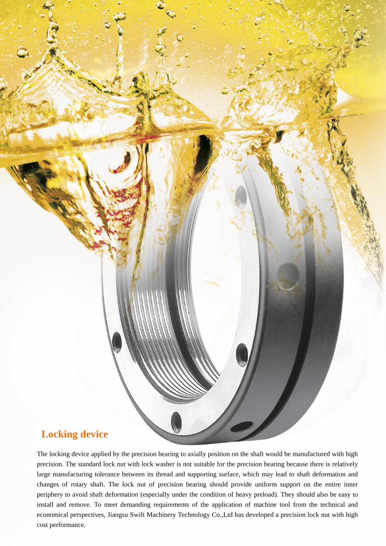
The locking device applied by the precision bearing to axially position on the shaft would be manufactured with high
precision. The standard lock nut with lock washer is not suitable for the precision bearing because there is relatively
large manufacturing tolerance between its thread and supporting surface, which may lead to shaft deformation and
changes of rotary shaft. The lock nut of precision bearing should provide uniform support on the entire inner
periphery to avoid shaft deformation (especially under the condition of heavy preload). They should also be easy to
install and remove. To meet demanding requirements of the application of machine tool from the technical and
economical perspectives, Jiangsu Swift Machinery Technology Co.,Ltd has developed a precision lock nut with high
cost performance.
Locking device
Content
Precision lock nut
SWT/R series
SWT/F series
SWT/K series
SWT/A series
SWT/N series
SWT/FA series
SWT/RN series
SWT/AN series
Bearing hydraulic nut
SWT/THC series
Hydraulic nut
SWT/YTC series
Wedge block/bridge-type press block
300 /15 0 /80series
Schematic diagram of SWT ball screw
List of SWT bearing seats
SWT square supporting seat

Locking device
Multiple designs
Jiangsu Swift Machinery Technology Co.,Ltd can manufacture multiple types of precision lock nuts with lock-pin. Here we
illustrate two types: R-type and F-type.
With two kinds of such nuts, bearings can be easily and reliably axially positioned on the shaft with other parts with high
precision. Their specialty is three phosphor bronze lock pins uniformly distributed along the periphery. These pins are fixed
on the screw thread of the shaft by inner hexagonal flat screws to prevent rotation of the nuts. Both the installation and
design are simple, without extra lock washer or groove on the shaft. The lock pin and flat screw keep an angle with the axis
the same as that of the thread surface. The end of lock nut is processed in the same process with that of the thread, so it also
features thread form. The nut is locked in place completely relying on the friction between the lock pin and axial thread as
well as the cohesive frictions between thread surfaces. Therefore, the lock pin cannot bear the axial load forced on the nut.
Once the nut is locked, the thread surface will not release axial load and the nut will not be deformed (Figure1). Another
advantage of F-type nut is that it can be adjusted. Three lock nuts with equal spaces can precisely position the nut, keep it
perpendicular to the shaft. The lock pin can also be used to correct the inaccuracy and deviations of other parts to be
installed on the shaft. Due to that the lock pin will not be changed in the form, R-type and F-type nuts can ensure their
precision even after multiple assembly and dis-assembly.
Figure 2 displays an application case for F-type lock nut.
Major data
Tolerance
Screw thread is manufactured according to 4H precision with 4H tolerance and vertical precision of 0.005mm.
Material
Lock nut is made of high-rigid steel (42CrMo), with rigidity of HRC28° —32°; its surface is coated with phosphate and
lubricated. Lock pin applies phosphor bronze. Flat screw is 12.9-grade bolt with high-strength.
Installation
It is quite easy to install R-type and F-type lock nuts. There are grooves around the periphery. Select wrenches of different
types according to applications and size of nuts, including claw wrench and impact wrench (Figure 3). Product list has
shown the corresponding sizes for wrenches and keys (for flat screw).
In order to securely lock the R-type or F-type lock nut, please firstly tighten the flat screw slightly until the thread of lock
pin is matched with the thread of the shaft. Then alternatively and evenly screw up the flat screws tightly until the tightening
torque shown in the product list is reached.
Please correct the misalignment between the supporting surface of the thread with the components nearby. Firstly, loosen
the flat screw in a place with the maximum deviation and tighten the other two screws to the same extent. Then remove the
loosened screw. If the required precision has not been reached, repeat the above steps until it is perfectly corrected.
Dis-assembly
In dis-assembling the R-type or F-type lock nut, please ensure that the lock pin is meshed with the thread of the shaft.
Hitting the nut slightly in the vicinity of the flat screw by rubber hammer can loosen the lock pin, which can help to easily
take the nut off the thread of the shaft.
Figure 1 Figure 2 Figure 3

Thread Axial Load
static(kN)
Flat screw
tightening torque
(Nm)
Loosening Torque (Nm)
SWT/F SWT/R SWT/K SWT/N SWT/A
M8 30 4.5 - 17 - - -
M10 35 4.5 - 18 - - -
M12 40 4.5 - 19 - - -
M15 60 4.5 - 20 - - -
M17 80 8.0 27 21 90 63 25
M20 90 8.0 28 24 99 69 26
M25 130 8.0 30 26 101 70 28
M30 160 8.0 32 28 102 71 29
M35 190 18 39 34 109 76 37
M40 210 18 46 36 110 77 42
M45 240 18 61 56 127 的 59
M50 300 18 70 63 137 96 66
M55 340 18 88 68 166 166 74
M60 380 18 98 96 205 205 81
M65 460 18 127 112 254 254 88
M70 490 18 147 137 313 313 98
M75 520 18 152 145 382 382 103
M80 620 18 156 149 460 460 113
M85 650 18 176 168 5钧 549 128
M90 680 18 186 178 656 656 137
M95 710 18 201 193 745 745 152
M100 740 18 220 210 833 833 172
M105 770 35 236 215 - - 186
M110 800 35 252 230 1127 1127 206
M115 830 35 268 250 - - 221
M120 860 35 279 264 1323 1323 235
M125 890 35 289 274 - - 250
M130 920 35 313 294 - - 265
M135 950 35 352 328 - - 304
M140 980 35 392 372 - - 324
M145 1010 35 436 402 - - 353
M150 1040 35 480 421 - - 392
M155 1070 35 519 460 - - 422
M160 1100 35 563 509 - - 461
M165 1130 35 598 529 - - 495
M170 1160 35 647 558 - - 520
M180 1220 60 686 558 - - 559
M190 1280 60 735 627 - - 598
M200 1340 60 794 666 - - 637

Thread D h n-g t d n-m MAX.Nm
SWT/R M8×0.75 16 8 3—3 1.6 13 2-M4 3.5
SWT/RM10×0.75 18 8 3—3 1.6 15 2-M4 3.5
SWT/R M10×1.0 18 8 3—3 1.6 15 2-M4 3.5
SWT/R M12×1.0 20 8 3—3 1.6 17 2-M4 3.5
SWT/R M12×1.25 20 8 3—3 1.6 17 2-M4 3.5
SWT/R M14×1.5 25 8 3—3 2 21 2-M4 3.5
SWT/R M15×1.0 25 8 3—3 1.8 21.5 2-M4 3.5
SWT/R M16×1.5 28 10 3—4 2 24 2-M5 4.5
SWT/R M17×1.0 28 10 3—4 2 24 2-M5 4.5
SWT/R M18×1.5 30 10 3—4 2 26 2-M5 4.5
SWT/R M20×1.0 32 10 3—4 2 28 3-M5 4.5
SWT/RM20×1.5 32 10 3—4 2 28 3-M5 4.5
SWT/RM22×1.5 35 10 3—4 2 31 3-M5 4.5
SWT/RM24×1.5 38 12 3—5 2 34 3-M6 8
SWT/RM25×1.5 38 12 3—5 2 34 3-M6 8
SWT/RM27×1.5 42 12 3—5 2 38 3-M6 8
SWT/R M30×1.0 45 12 3—5 2 41 3-M6 8
SWT/RM30×1.5 45 12 3—5 2 41 3-M6 8
SWT/RM33×1.5 52 12 3—5 2 48 3-M6 8
SWT/RM35×1.5 52 12 3—5 2 48 3-M6 8
SWT/RM36×1.5 55 14 3—6 2.5 50 3-M6 8
SWT/RM38×1.5 56 14 3—6 2.5 51 3-M6 8
SWT/RM39×1.5 58 14 3—6 2.5 53 3-M6 8
SWT/RM40×1.5 58 14 3—6 2.5 53 3-M6 8
SWT/RM42×1.5 62 14 3—6 2.5 57 3-M6 8
SWT/RM45×1.5 65 14 3—6 2.5 60 3-M6 8
SWT/RM48×1.5 68 14 3—6 2.5 63 3-M6 8
SWT/RM50×1.5 70 14 3—6 2.5 65 3-M8 18
SWT/RM52×1.5 73 16 3—7 3 67 3-M8 18
SWT/R M55×2.0 75 16 3—7 3 69 3-M8 18
SWT/R M56×2.0 77 16 3—7 3 71 3-M8 18
SWT/R M60×2.0 80 16 3—7 3 74 3-M8 18
SWT/R M64×2.0 85 16 3—7 3 79 3-M8 18
SWT/R M65×2.0 85 16 3—7 3 79 3-M8 18
SWT/R M68×2.0 92 18 3—6 3.5 85 3-M8 18
SWT/R M70×2.0 92 18 3—6 3.5 85 3-M8 18
SWT/R M72×2.0 95 18 3—6 3.5 88 3-M8 18
Precision lock nut
SWT/R series
The locking method of SWT/R series is axial three-point locking. With thinner
thickness, it is suitable for the installation environment which is restricted in the
thickness. Because lock copper is perpendicular to the male screw thread in axial
locking, over-large tightening torque of lock copper may easily lessen the axial load
of the nut.
Material: 42CrMo
Hardness: HRC28°—32°
Thread precision: ISO4H Plane deflection: 0.005mm
6. Remark: (1) The above data is just provided for reference, Jiangsu Swift Machinery Technology Co.,Ltd reserves
the right to revise it.(2) 1NM=10.2kgf.cm=0.73Ib.ft (3) Non-standard nut can be customized.

Thread D h n-g t d n-m MAX.Nm
SWT/R M75×2.0 98 18 3—8 3.5 91 3-M8 18
SWT/R M76×2.0 100 18 3—8 3.5 93 3-M8 18
SWT/R M80×2.0 105 18 6—8 3.5 98 3-M8 18
SWT/R M85×2.0 110 18 6—8 3.5 103 3-M8 18
SWT/R M90×2.0 120 20 6—10 4 112 3-M8 18
SWT/R M95×2.0 125 20 6—10 4 117 3-M8 18
SWT/R M100×2.0 130 20 6—10 4 122 3-M8 18
SWT/R M105×2.0 140 22 6—12 5 130 3-M8 18
SWT/R M110×2.0 145 22 6—12 5 135 3-M8 18
SWT/R M115×2.0 150 22 6—12 5 140 3-M8 18
SWT/R M120×2.0 155 24 6—12 5 145 3-M8 18
SWT/R M125×2.0 160 24 6—12 5 150 3-M8 18
SWT/R M130×2.0 165 24 6—12 5 155 3-M8 18
SWT/R M135×2.0 175 26 6—14 6 163 3-M10 35
SWT/R M140×2.0 180 26 6—14 6 168 3-M10 35
SWT/R M145×2.0 190 26 6—14 6 178 3-M10 35
SWT/R M150×2.0 195 26 6—14 6 183 3-M10 35
SWT/R M155×3.0 200 28 6—16 7 186 3-M10 35
SWT/R M160×3.0 210 28 6—16 7 196 3-M10 35
SWT/R M165×3.0 210 28 6—16 7 196 3-M10 35
SWT/R M170×3.0 220 28 6—16 7 206 3-M10 35
SWT/R M180×3.0 230 30 6—18 8 214 3-M12 60
SWT/R M190×3.0 240 30 6—18 8 224 3-M12 60
SWT/R M200×3.0 250 32 6—18 8 234 3-M12 60
SWT/R M210×4.0 270 34 6—18 8 245 3-M12 85
SWT/R M220×3.0 270 34 6—18 8 245 3-M12 85
SWT/R M220×4.0 270 34 6—18 8 254 3-M12 85
SWT/R M230×3.0 280 34 6—18 8 264 3-M12 85
SWT/R M240×3.0 290 34 6—18 8 265 3-M12 85
SWT/R M240×4.0 290 34 6—18 8 274 3-M12 85
SWT/R M245×3.0 295 34 6—18 8 279 3-M12 85
SWT/R M260×3.0 310 36 6—18 8 285 3-M12 85
SWT/R M260×4.0 310 36 6—18 8 294 3-M12 85
SWT/R M275×4.0 325 36 6—18 8 309 3-M12 85
SWT/R M280×4.0 330 36 6—18 8 314 3-M12 85
SWT/R M300×4.0 350 36 6—18 8 334 3-M12 85
SWT/R M440×4.0 520 46 6—20 10 500 6-M20 85
SWT/R M460×4.0 540 46 6—20 10 520 6-M20 85

Thread D h d n-g t n-m MAX.Nm
SWT/F M12×1.5P 30 14 26 3—4 2 3-M5 4.5
SWT/FM14×1.5P 30 14 26 3—4 2 3-M5 4.5
SWT/F M15×1 0P 30 14 26 3—4 2 3-M5 4.5
SWT/F M16×1.5P 30 14 26 3—4 2 3-M5 4.5
SWT/F M17×1 0P 32 16 28 3—4 2 3-M5 4.5
SWT/F M18×1.5P 32 16 28 3—4 2 3-M5 4.5
SWT/F M20×1 0P 38 16 34 3—4 2 3-M5 4.5
SWT/F M20×1.5P 38 16 34 3—4 2 3-M6 8
SWT/F M22×1 5P 38 16 34 3—4 2 3-M6 8
SWT/F M24×1.5P 38 18 34 3—5 2 3-M6 8
SWT/F M25×1 5P 38 18 34 3—5 2 3-M6 8
SWT/F M27×1.5P 40 18 36 3—5 2 3-M6 8
SWT/F M30×1 5P 45 18 41 3—5 2 3-M6 8
SWT/F M33×1.5P 50 18 46 3—5 2 3-M6 8
SWT/F M35×1 5P 52 18 48 3—5 2 3-M8 18
SWT/F M36×1.5P 52 18 48 3—5 2 3-M8 18
SWT/F M39×1 5P 58 20 53 3—6 2.5 3-M8 18
SWT/F M40×1.5P 58 20 53 3—6 2.5 3-M8 18
SWT/F M42×1 5P 62 20 57 3—6 2.5 3-M8 18
SWT/F M45×1.5P 65 20 60 3—6 2.5 3-M8 18
SWT/F M48×1.5P 70 20 65 3—6 2.5 3-M8 18
SWT/F M50×1.5P 70 20 65 3—6 2.5 3-M8 18
SWT/F M52×1.5P 73 22 67 3—7 3 3-M8 18
SWT/F M55×1.5P 75 22 69 3—7 3 3-M8 18
SWT/F M55×2.0P 75 22 69 3—7 3 3-M8 18
SWT/F M56×1.5P 75 22 69 3—7 3 3-M8 18
SWT/F M56×2.0P 75 22 69 3—7 3 3-M8 18
SWT/F M60×2.0P 80 22 74 3—7 3 3-M8 18
SWT/F M64×1.5P 85 22 79 3—7 3 3-M8 18
SWT/F M64×2.0P 85 22 79 3—7 3 3-M8 18
SWT/F M65×2.0P 85 22 79 3—7 3 3-M8 18
SWT/F M68×2.0P 92 24 85 3—8 3.5 3-M8 18
SWT/F M70×2.0P 92 24 85 3—8 3.5 3-M8 18
SWT/F M72×2.0P 94 24 87 3—8 3.5 3-M8 18
SWT/F M75×2.0P 98 24 91 3—8 3.5 3-M8 18
SWT/F M76×2.0P 98 24 91 3—8 3.5 3-M8 18
SWT/F M80×2.0P 105 24 98 3—8 3.5 3-M8 18
Precision lock nut
SWT/F series
For SWT/F series locking nut, its lock copper keeps a angle of 30 degree with the
thread. It does not bear the axial load forced on the thread. Once the nut is locked, the
thread surface will not release axial load and the nut will not be deformed. Three lock
nuts with equal spaces can precisely position the nut, keep it perpendicular to the
shaft. F-type nuts can ensure their precision even after multiple assembly and
dis-assembly.
Material: 42CrMo
Hardness: HRC28°—32°
Thread precision: ISO4H
Plane deflection: 0.005mm
8.Remark: (1) The above data is just provided for reference, Jiangsu Swift Machinery Technology Co.,Ltd reserves the
right to revise it.(2) 1NM=10.2kgf.cm=0.73Ib.ft (3) Non-standard nut can be customized.

Thread D h d n-g t n-m MAX.Nm
SWT/F M85×2.0P 110 24 103 3—8 3.5 3-M8 18
SWT/F M90×2.0P 120 26 112 6—10 4 3-M8 18
SWT/F M95×2.0P 125 26 117 6—10 4 3-M8 18
SWT/F M100×2.0P 130 26 122 6—10 4 3-M8 18
SWT/F M105×2.0P 140 28 132 6—10 4 3-M10 35
SWT/F M110×2.0P 145 28 137 6—10 4 3-M10 35
SWT/F M115×2.0P 150 28 142 6—10 4 3-M10 35
SWT/F M120×2.0P 155 30 145 6—12 5 3-M10 35
SWT/F M125×2.0P 160 30 150 6—12 5 3-M10 35
SWT/F M130×2.0P 165 30 155 6—12 5 3-M10 35
SWT/F M135×2.0P 175 32 165 6—12 5 3-M10 35
SWT/F M140×2.0P 180 32 170 6—12 5 3-M10 35
SWT/F M145×2.0P 190 32 180 6—12 5 3-M10 35
SWT/F M150×2.0P 195 32 185 6—12 5 3-M10 35
SWT/F M155×3.0P 200 34 188 6—14 6 3-M10 35
SWT/F M160×3.0P 210 34 198 6—14 6 3-M10 35
SWT/F M165×3.0P 210 34 198 6—14 6 3-M10 35
SWT/F M170×3.0P 220 34 208 6—14 6 3-M10 35
SWT/F M180×3.0P 230 36 216 6—16 7 3-M12 60
SWT/F M190×3.0P 240 36 226 6—16 7 3-M12 60
SWT/F M200×3.0P 250 38 236 6—16 7 3-M12 60
SWT/F M210×4.0P 270 38 250 6—16 8 3-M12 85
SWT/F M220×3.0P 270 38 250 6—20 10 3-M12 85
SWT/F M220×4.0P 270 38 250 6—20 10 3-M12 85
SWT/F M240×3.0P 290 38 270 6—20 10 3-M12 85
SWT/F M240×4.0P 290 38 270 6—20 10 3-M12 85
SWT/F M260×3.0P 310 38 290 6—20 10 3-M12 85
SWT/F M260×4.0P 310 38 290 6—20 10 3-M12 85
SWT/F M270×4.0P 320 38 300 6—20 10 3-M12 85
SWT/F M280×4.0P 330 38 310 6—20 10 3-M12 85
SWT/F M300×4.0P 360 42 336 6—24 12 3-M12 85

Thread D h d n-M×L C n b MAX.Nm
SWT/KM18×1.5P 38 18 34 4-M4×12 28 4 4 3.5
SWT/KM20×1.0P 40 18 36 4-M4×12 30 4 4 3.5
SWT/K M20×1.5P 40 18 36 4-M4×12 30 4 4 3.5
SWT/KM22×1.5P 42 18 38 4-M4×12 32 4 4 3.5
SWT/K M24×1.5P 44 18 41 4-M4×12 34 4 4 3.5
SWT/K M25×1.5P 45 20 41 4-M4×14 35 4 5 3.5
SWT/K M26×1.5P 45 20 41 4-M4×14 35 4 5 3.5
SWT/K M27×1.5P 46 20 43 4-M4×14 37 4 5 3.5
SWT/K M28×1.5P 46 20 43 4-M4×14 37 4 5 3.5
SWT/K M30×1.5P 48 20 45 4-M4×14 39 4 5 3.5
SWT/K M32×1.5P 50 20 47 4-M4×14 41 4 5 3.5
SWT/K M33×1.5P 50 22 47 4-M4×16 41 4 5 3.5
SWT/K M35×1.5P 53 22 50 4-M4×16 44 4 5 3.5
SWT/K M36×1.5P 53 22 50 4-M4×16 44 4 5 3.5
SWT/K M38×1.5P 56 22 53 4-M4×16 47 4 5 3.5
SWT/K M39×1.5P 56 22 53 4-M4×16 47 4 5 3.5
SWT/K M40×1.5P 58 22 55 4-M4×16 49 4 5 3.5
SWT/K M42×1.5P 60 22 57 4-M4×16 51 4 5 3.5
SWT/K M45×1.5P 68 22 63 6-M4×16 57 6 6 3.5
SWT/K M48×1.5P 69 25 65 6-M4×18 58 6 6 3.5
SWT/K M50×2.0P 70 25 66 6-M4×18 60 6 6 3.5
SWT/K M52×2.0P 72 25 68 6-M4×18 62 6 6 3.5
SWT/K M55×1.5P 75 25 71 6-M4×18 65 6 6 3.5
SWT/K M55×2.0P 75 25 71 6-M4×18 65 6 6 4.5
SWT/K M56×1.5P 82 26 77 6-M5×18 70 6 6 4.5
SWT/K M56×2.0P 82 26 77 6-M5×18 70 6 6 4.5
SWT/K M58×1.5P 82 26 77 6-M5×18 70 6 6 4.5
SWT/K M60×1.5P 84 26 79 6-M5×18 72 6 6 4.5
SWT/K M60×2.0P 84 26 79 6-M5×18 72 6 6 4.5
SWT/K M62×1.5P 86 28 82 6-M5×20 75 6 6 4.5
SWT/K M64×1.5P 86 28 82 6-M5×20 75 6 6 4.5
SWT/K M64×2.0P 86 28 82 6-M5×20 75 6 6 4.5
SWT/K M65×1.5P 88 28 84 6-M5×20 77 6 6 4.5
SWT/K M65×2.0P 88 28 84 6-M5×20 77 6 6 4.5
SWT/K M68×1.5P 93 28 89 6-M5×20 80 6 7 4.5
SWT/K M68×2.0P 93 28 89 6-M5×20 80 6 7 4.5
SWT/K M70×1.5P 95 28 89 6-M5×20 82 6 7 4.5
SWT/K M70×2.0P 95 28 89 6-M5×20 82 6 7 4.5
SWT/K M72×1.5P 97 28 91 6-M5×20 84 6 7 4.5
SWT/K M72×2.0P 97 28 91 6-M5×20 84 6 7 4.5
10.Remark: (1) The above data is just provided for reference, Jiangsu Swift Machinery Technology Co.,Ltd reserves
the right to revise it.(2) 1NM=10.2kgf.cm=0.73Ib.ft (3) Non-standard nut can be customized.
Precision lock nut
SWT/K series
4 to 6 high-strength bolts are applied by a SWT/K series lock nut, which can axially
deform the thread to ensure the fastening. It is suitable for severe working
environment where nuts may easily been loosen and high torque is required. The nut
deflection precision can be adjusted by regulating the tightening force of the axial
screw.
Material: 42CrMo
Hardness: HRC28°—32°
Thread precision: ISO4H Plane deflection: 0.007mm

Thread D h d n-M×L C n b MAX.Nm
SWT/K M75×1.5P 100 28 94 6-M5×20 87 6 7 4.5
SWT/K M75×2.0P 100 28 94 6-M5×20 87 6 7 4.5
SWT/K M78×1.5P 110 32 102 6-M6×22 94 6 8 4.5
SWT/K M80×2.0P 110 32 103 6-M6×22 95 6 8 8
SWT/K M85×2.0P 115 32 108 6-M6×22 100 6 8 8
SWT/K M88×1.5P 120 32 112 6-M6×22 104 6 8 8
SWT/K M90×2.0P 120 32 113 6-M6×22 105 6 8 8
SWT/K M95×2.0P 125 32 118 6-M6×22 110 6 8 8
SWT/K M100×2.0P 130 32 123 6-M6×22 115 6 8 8
SWT/K M105×2.0P 135 32 128 6-M6×22 120 6 8 8
SWT/K M110×2.0P 140 32 133 6-M6×22 125 6 8 8
SWT/K M115×2.0P 145 34 138 6-M6×22 130 6 8 8
SWT/K M116×2.0P 145 34 138 6-M6×22 130 6 8 8
SWT/K M120×2.0P 155 36 146 6-M6×25 136 6 8 8
SWT/K M125×2.0P 160 36 150 6-M6×25 140 6 8 8
SWT/K M130×2.0P 165 36 156 6-M6×25 148 6 8 8
SWT/K M130×3.0P 165 36 156 6-M6×25 148 6 8 8
SWT/K M140×2.0P 180 38 168 6-M6×25 160 8 10 8
SWT/K M140×3.0P 180 38 168 8-M6×25 160 8 10 8
SWT/K M150×2.0P 190 38 178 8-M6×25 170 8 10 8
SWT/K M150×3.0P 190 38 178 8-M6×25 170 8 10 8
SWT/K M160×3.0P 205 40 193 8-M8×30 182 8 10 18
SWT/K M170×3.0P 215 40 204 8-M8×30 193 8 10 18
SWT/K M180×3.0P 230 40 216 8-M8×30 205 8 10 18
SWT/K M190×3.0P 240 40 226 8-M8×30 215 8 10 18
SWT/K M200×3.0P 245 40 234 8-M8×30 223 8 10 18
SWT/K M210×4.0P 265 40 253 8-M8×25 243 8 10 18
SWT/K M220×3.0P 265 40 255 8-M8×30 243 8 10 18
SWT/K M220×4.0P 265 40 253 8-M8×30 243 8 10 18
SWT/K M225×3.0P 275 42 260 8-M10×30 247 8 10 18
SWT/K M230×3.0P 275 42 265 8-M10×30 251 8 10 18
SWT/K M235×3.0P 285 42 270 8-M10×30 257 8 10 18
SWT/K M240×3.0P 285 42 275 8-M10×30 261 8 10 35
SWT/K M250×4.0P 295 42 285 8-M10×30 271 8 12 35
SWT/K M260×3.0P 305 42 295 8-M10×30 283 8 12 35
SWT/K M270×4.0P 315 42 305 8-M10×30 293 8 12 35
SWT/K M280×4.0P 325 42 315 8-M10×30 303 8 12 35
SWT/K M295×4.0P 340 42 331 8-M10×30 318 8 12 35
SWT/K M300×4.0P 345 42 335 8-M10×30 323 8 12 35

Thread D h n-g t d n-m MAX.Nm
SWT/A M12×1.25P 26 14 3—3 2 22 2-M4 3.5
SWT/AM14×1.5P 30 14 3—4 2 26 2-M4 3.5
SWT/A M15×1.0P 30 14 3—4 2 26 2-M4 3.5
SWT/A M16×1.5P 30 14 3—4 2 26 2-M4 3.5
SWT/A M17×1.0P 32 16 3—4 2 28 2-M4 3.5
SWT/A M18×1.5P 32 16 3—4 2 28 3-M4 3.5
SWT/A M20×1.0P 38 16 3—4 2 34 3-M4 3.5
SWT/A M20×1.5P 38 16 3—4 2 34 3-M4 3.5
SWT/A M22×1.5P 38 16 3—4 2 34 3-M4 3.5
SWT/A M24×1.5P 38 18 3—5 2 34 3-M4 3.5
SWT/A M25×1.5P 38 18 3—5 2 34 3-M4 3.5
SWT/A M27×1.5P 40 18 3—5 2 36 3-M4 3.5
SWT/A M30×1.5P 45 18 3—5 2 41 3-M4 3.5
SWT/A M33×1.5P 50 18 3—5 2 46 3-M4 3.5
SWT/A M35×1.5P 52 18 3—5 2 48 3-M6 8
SWT/A M36×1.5P 52 18 3—5 2 48 3-M6 8
SWT/A M39×1.5P 58 20 3—6 2.5 53 3-M6 8
SWT/A M40×1.5P 58 20 3—6 2.5 53 3-M6 8
SWT/A M42×1.5P 62 20 3—6 2.5 57 3-M6 8
SWT/A M45×1.5P 65 20 3—6 2.5 60 3-M6 8
SWT/A M48×1.5P 70 20 3—6 2.5 65 3-M6 8
SWT/A M50×1.5P 70 20 3—6 2.5 65 3-M6 8
SWT/A M50×2.0P 70 20 3—6 2.5 65 3-M6 8
SWT/A M52×1.5P 73 22 3—7 3 67 3-M6 8
SWT/A M55×2.0P 75 22 3—7 3 69 3-M6 8
SWT/A M56×2.0P 75 22 3—7 3 69 3-M6 8
SWT/A M60×2.0P 80 22 3—7 3 74 3-M6 8
SWT/A M64×2.0P 85 22 3—7 3 79 3-M6 8
SWT/A M65×2.0P 85 22 3—7 3 79 3-M6 8
SWT/A M68×2.0P 92 24 3—6 3.5 85 3-M8 18
SWT/A M70×2.0P 92 24 3—6 3.5 85 3-M8 18
SWT/A M72×2.0P 94 24 3—6 3.5 87 3-M8 18
SWT/A M75×2.0P 98 24 3—6 3.5 91 3-M8 18
SWT/A M76×2.0P 98 24 3—6 3.5 91 3-M8 18
SWT/A M80×2.0P 105 24 4—6 3.5 98 3-M8 18
SWT/A M85×2.0P 110 24 4—6 3.5 103 3-M8 18
SWT/A M90×2.0P 120 26 4—10 4 112 3-M8 18
12. Remark: (1) The above data is just provided for reference, Jiangsu Swift Machinery Technology Co.,Ltd reserves
the right to revise it.(2) 1NM=10.2kgf.cm=0.73Ib.ft (3) Non-standard nut can be customized.
Precision lock nut
SWT/A series
The locking method of SWT/A series is three-point locking, with thickness the same
with that of the F-type nut. Axial three-point locking is its feature, applicable for
special environment restrictions of assembly.
Material: 42CrMo
Hardness: HRC28°—32°
Thread precision: ISO4H Plane deflection: 0.005mm

Thread D h n-g t d n-m MAX.Nm
SWT/A M95×2.0P 125 26 4—10 4 117 3-M8 18
SWT/AM100×2.0P 130 26 4—10 4 122 3-M8 18
SWT/A M105×2.0P 140 28 4—12 5 130 3-M8 18
SWT/A M110×2.0P 145 28 4—12 5 135 3-M8 18
SWT/A M115×2.0P 150 28 4—12 5 140 3-M8 18
SWT/A M120×2.0P 155 30 4—12 5 145 3-M8 18
SWT/A M125×2.0P 160 30 4—12 5 150 3-M8 18
SWT/A M130×2.0P 165 30 4—12 5 155 3-M8 18
SWT/A M135×2.0P 175 32 4—14 6 163 3-M10 35
SWT/A M140×2.0P 180 32 4—14 6 168 3-M10 35
SWT/A M145×2.0P 190 32 4—14 6 178 3-M10 35
SWT/A M150×2.0P 195 32 4—14 6 183 3-M10 35
SWT/A M155×3.0P 200 34 4—16 7 186 3-M10 35
SWT/A M160×3.0P 210 34 4—16 7 196 3-M10 35
SWT/A M165×3.0P 210 34 4—16 7 196 3-M10 35
SWT/A M170×3.0P 220 34 4—16 7 206 3-M10 35
SWT/A M180×3.0P 230 36 4—18 8 214 3-M12 60
SWT/A M190×3.0P 240 36 4—18 8 224 3-M12 60
SWT/A M200×3.0P 250 38 4—18 8 234 3-M12 60
SWT/A M210×4.0P 270 38 4—18 8 250 3-M12 60
SWT/A M220×3.0P 270 38 4—18 8 254 3-M12 85
SWT/A M220×4.0P 270 38 4—18 8 254 3-M12 85
SWT/A M240×4.0P 290 38 4—18 8 270 3-M12 85
SWT/A M260×3.0P 310 38 4—18 8 290 3-M12 85
SWT/A M260×4.0P 310 38 4—18 8 290 3-M12 85
SWT/A M280×4.0P 330 40 4—18 8 310 3-M12 85
SWT/A M300×4.0P 350 40 4—18 8 330 3-M12 85

Thread D h d n-m t c b MAX.Nm
SWT/N M16×1.5 30 18 26 4-M5 5 5.5 4 4.5
SWT/NM17×1.0 32 18 28 4-M5 5 5.5 4 4.5
SWT/N M17×1.5 32 18 28 4^M5 5 5.5 4 4.5
SWT/N M18×1.5 36 18 32 4-M5 6 5.5 4 4.8
SWT/N M20×1.5 38 18 34 4-M6 6 5.5 4 8
SWT/NM22×1.5 40 18 36 4-M6 6 5.5 4 8
SWT/N M24×1.5 45 18 41 4-M6 7 5.5 5 8
SWT/NM25×1.5 45 20 41 4-M6 7 6 5 8
SWT/N M27×1.5 46 20 42 4-M6 7 6 5 8
SWT/NM28×1.5 46 20 42 4-M6 7 6 5 8
SWT/N M30×1.5 52 20 48 4-M6 7 6 5 8
SWT/NM32×1.5 54 22 49 4-M6 7 7 6 8
SWT/N M33×1.5 54 22 49 4-M6 7 7 6 8
SWT/NM35×1.5 58 22 53 4-M6 7 7 6 8
SWT/N M36×1.5 58 22 53 4-M6 7 7 6 8
SWT/NM38×1.5 60 22 55 4-M6 8 7 6 8
SWT/N M39×1.5 60 22 55 4-M6 8 7 6 8
SWT/NM40×1.5 65 22 60 4-M6 8 7 6 8
SWT/N M42×1.5 65 22 60 4-M6 8 7 6 8
SWT/NM45×1.5 70 22 65 6-M6 8 7 6 8
SWT/N M48×1.5 75 25 70 6-M6 8 8 6 8
SWT/NM50×1.5 75 25 70 6-M6 8 8 6 8
SWT/N M52×1.5 80 25 74 6-M8 8 8 6 8
SWT/NM55×1.5 85 25 79 6-M8 8 8 6 18
SWT/N M55×2.0 85 25 79 6-M8 8 8 6 18
SWT/N M56×2.0 85 26 79 6-M8 8 8 6 18
SWT/N M60×2.0 90 26 84 6-M8 10 8 6 18
SWT/N M64×2.0 95 28 89 6-M8 10 8.5 8 18
SWT/N M65×2.0 95 28 89 6-M8 10 8.5 8 18
SWT/N M68×2.0 98 28 91 6-M8 10 8.5 8 18
SWT/N M70×2.0 100 28 93 6-M8 10 9 8 18
SWT/N M75×2.0 106 28 99 6-M10 10 9 8 35
SWT/N M80×2.0 110 30 103 6-M10 10 9.5 8 35
SWT/N M85×2.0 115 32 108 6-M10 10 10 8 35
SWT/N M90×2.0 120 32 112 6-M10 10 10 8 35
SWT/N M95×2.0 125 32 117 6-M10 10 10 8 35
SWT/N M100×2.0 130 32 122 8-M10 10 10 8 35
14.Remark: (1) The above data is just provided for reference, Jiangsu Swift Machinery Technology Co.,Ltd reserves
the right to revise it.(2) 1NM=10.2kgf.cm=0.73Ib.ft (3) Non-standard nut can be customized.
Precision lock nut
SWT/N series
SWT/N series is locked by applying 4 to 6 high-strength flat screw to support the end
surface, which relies on the elasticity of the steel itself to deform the thread and
complete the locking. The external dimension is close to and can be interchanged
with F-type nut. N-type nut is applicable for installation where the nut is easily
loosen and the space is limited. Its locking capacity is larger than F-type nut by at
least 2 times.
Material: 42CrMo
Hardness: HRC28°—32°
Thread precision: ISO4H
Plane deflection: 0.005mm

Thread D h d n-m t c b MAX.Nm
SWT/N M105×2.0 135 32 125 8-M10 10 10 8 35
SWT/N M110×2.0 140 32 130 8-M10 10 10.5 8 35
SWT/N M115×2.0 145 34 135 8-M10 10 10.5 8 35
SWT/N M120×2.0 150 36 140 8-M10 10 11 10 35
SWT/N M125×2.0 160 36 150 8-M10 10 11 10 35
SWT/N M130×2.0 165 36 155 8-M10 10 11 10 35
SWT/N M135×2.0 175 38 163 8-M12 10 12 10 60
SWT/N M140×2.0 180 38 168 8-M12 10 12 10 60
SWT/N M145×2.0 190 38 178 8-M12 10 11.5 10 60
SWT/N M150×2.0 195 38 183 8-M12 10 12 10 60
SWT/N M155×2.0 200 38 186 8-M12 12 11 10 60
SWT/N M160×3.0 210 40 196 8-M12 12 12.5 12 60
SWT/N M170×3.0 220 40 206 8-M12 12 12.5 12 60
SWT/N M180×3.0 230 40 214 8-M12 12 12.5 12 60
SWT/N M190×3.0 240 40 224 8-M12 12 12.5 12 60
SWT/N M200×3.0 250 40 234 8-M12 12 12.5 12 60

Thread d1 D d d2 h g t M MAX.Nm
SWT/FAM12×1.0P 23 30 25 13 14 4 2.5 27 4.5
SWT/FAM15×1.0P 26 33 28 16 16 4 2.5 30 4.5
SWT/FAM17×1.0P 29 37 33 18 18 5 2.5 34 8.0
SWT/FAM20×1.0P 32 40 35 21 18 5 2.5 36 8.0
SWT/FAM25×1.5P 36 44 39 26 20 5 2.5 41 8.0
SWT/FAM30×1.5P 41 49 44 32 20 5 2.5 46 8.0
SWT/FAM35×1.5P 46 54 49 38 22 5 2.5 50 8.0
SWT/FAM40×1.5P 56 65 59 42 22 6 3 60 8.0
SWT/FAM4S×1.5P 61 70 64 48 22 6 3 65 8.0
SWT/FAM50×1.5P 65 75 68 52 25 7 3.5 70 8.0
SWT/FA M55×2.0P 74 85 78 58 25 7 3.5 80 18.0
SWT/FA M60×2.0P 78 90 82 62 26 8 4 85 18.0
SWT/FA M65×2.0P 83 95 87 68 28 8 4 90 18.0
SWT/FA M70×2.0P 88 100 92 72 28 8 4 95 18.0
SWT/FA M75×2.0P 93 105 97 77 28 8 4 100 18.0
SWT/FA M80×2.0P 98 110 100 83 32 8 3.5 100 18.0
SWT/FA M85×2.0P 107 120 110 88 32 10 4 110 35.0
SWT/FA M90×2.0P 112 125 115 93 32 10 4 115 35.0
SWT/FA M95×2.0P 117 130 120 98 32 10 4 120 35.0
SWT/FA M100×2.0P 122 135 125 103 32 10 4 130 35.0
SWT/FA M110×2.0P 132 145 134 112 32 10 4 140 35.0
SWT/FA M120×2.0P 142 155 144 122 32 10 4 150 35.0
SWT/FA M130×2.0P 152 165 154 132 32 12 5 160 35.0
SWT/FA M140×2.0P 162 175 164 142 32 14 6 170 35.0
SWT/FA M150×2.0P 172 185 174 152 32 14 6 180 35.0
SWT/FA M160×2.0P 182 195 184 162 32 14 6 190 35.0
SWT/FA M170×2.0P 192 205 194 172 32 14 6 200 35.0
SWT/FA M180×2.0P 202 215 204 182 32 16 7 210 35.0
SWT/FA M190×2.0P 212 225 214 192 32 16 7 220 35.0
SWT/FA M200×2.0P 222 235 224 202 32 18 8 230 35.0
16.Remark: (1) The above data is just provided for reference, Jiangsu Swift Machinery Technology Co.,Ltd reserves
the right to revise it.(2) 1NM=10.2kgf.cm=0.73Ib.ft (3) Non-standard nut can be customized.
Precision lock nut
SWT/FA series
SWT/FA series lock nut has manufactured four grooves along the periphery. Nuts
with size of 15 and below has two planes rightly facing each other. Wrench can be
used to clamp it. This design is primarily used to meet requirements including high
precision, easy installation and steady locking.
Material: 42CrMo
Hardness: HRC28°—32°
Thread precision: ISO4H Plane deflection: 0.005mm

Thread D h d m L F MAX.Nm
SWT/RN M8×1 .0P 16 6.5 12 M4 3.5 14 0.9
SWT/RN M10×1.0P 19 8 14 M4 5 16 0.9
SWT/RN M12×1.0P 22 8 17 M4 5 19 3.5
SWT/RN M15×1.0P 25 10 20 M4 5.75 22 3.5
SWT/RN M17×1 .0P 29 11 22 M5 7 24 3.5
SWT/RN M20×1.0P 35 13 28 M5 7 30 8
SWT/RN M25×1.5P 43 15 33 M6 10 35 8
SWT/RN M30×1.5P 48 20 38 M8 12 40 8
SWT/RN M35×1.5P 60 21 48 M8 13 50 8
SWT/RN M40×1.5P 62 25 48 M8 18 50 8
Precision lock nut
SWT/RN series
SWT/RN series lock nut is square, which is applicable for the bearing supporting
seat. Inner thread and end surface are manufactured at the same time to ensure the
precision of the composition.
Material: 42CrMo
Hardness: HRC28°—32°
Thread precision: ISO4H Plane deflection: 0.005mm

Thread D h g t d
AN 0 M10×0.75P 18 4 3 2 13.5
AN 1 M12×1 .0P 22 4 3 2 17
AN 2 M15×1 .0P 25 5 4 2 21
AN 3 M17×1 .0P 28 5 4 2 22
AN 4 M20×1.0P 32 6 4 2 26
AN 5 M25×1.5P 38 7 5 2 32
AN 6 M30×1.5P 45 7 5 2 38
AN 7 M35×1.5P 52 8 5 2 44
AN 8 M40×1.5P 58 9 6 2.5 50
AN 9 M45×1.5P 65 10 6 2.5 56
AN 10 M50×1.5P 70 11 6 2.5 61
AN 11 M55×2.0P 75 11 7 3 67
AN 12 M60×2.0P 80 11 7 3 73
AN 13 M65×2.0P 85 12 7 3 79
AN 14 M70×2.0P 92 12 8 3.5 84
AN 15 M75×2.0P 98 13 8 3.5 90
AN 16 M80×2.0P 105 15 8 3.5 95
AN 17 M85×2.0P 110 16 8 3.5 102
AN 18 M90×2.0P 120 16 10 4 108
AN 19 M95×2.0P 125 17 10 4 113
AN 20 M100×2.0P 130 18 10 4 120
AN 21 M105×2.0P 140 18 12 5 126
AN 22 M110×2.0P 146 19 12 5 133
AN 23 M115×2.0P 150 19 12 5 137
Precision lock nut
SWT/AN series
SWT/AN series nut is featured with easy structure. Inner thread and end surface are
manufactured at the same time so that the deflection precision can be ensured.
Material: S45C
Hardness: HRC28°—32°
Thread precision: ISO4H Plane deflection: 0.005mm
18.Remark: (1) The above data is just provided for reference, Jiangsu Swift Machinery Technology Co.,Ltd reserves
the right to revise it.(2) 1NM=10.2kgf.cm=0.73Ib.ft (3) Non-standard nut can be customized.

Thread D h g t d
AN 24 M120×2.0P 155 20 12 5 138
AN 25 M125×2.0P 160 21 12 5 148
AN 26 M130×2.0P 165 21 12 5 149
AN 27M135×2.0P 175 22 14 6 160
AN 28 M140×2.0P 180 22 14 6 160
AN 29 M145×2.0P 190 24 14 6 172
AN 30 M150×2.0P 195 24 14 6 171
AN 31 M155×2.0P 200 25 16 7 182
AN 32 M160×3.0P 210 25 16 7 182
AN 33 M165×3.0P 210 26 16 7 193
AN 34 M170×3.0P 220 26 16 7 193
AN 36 M180×3.0P 230 27 18 8 203
AN 38 M190×3.0P 240 28 18 8 214
AN 40 M200×3.0P 250 29 18 8 226

Solutions to the Failures of SWIFT Nuts:
Failures Reasons Solutions
SWIFT nuts
cannot match
with and lock
into the external
thread.
1. Whether the inner thread pitch is
conforming to that of the external thread
pitch.
2. Whether the effective diameter of the
thread complies with the tolerance.
3. Whether there are damages and burrs
on the inner and external thread form.
4. Whether the left and right rotations of
inner and external thread are matched.
5. Whether the nominal outside diameter
of inner and external thread are matched.
6. Whether the outer diameter of
external thread is too large.
7. Whether the thread form of external
thread is standard.
1. Check whether the inner thread and external thread are
the same.
2. Check the external thread by the micrometer to ensure it
is accordance with the tolerance.
3. Check if there is any damage or burr on the external
thread. If yes, use the triangle diamond file to remove
it.
4. Check whether the left and right rotations of inner and
external thread are matched.
5. Check whether the inner and external diameter are the
same in sizes by the vernier caliper.
6. Use micrometer key groove to check the outer diameter.
7. Use optical projector to check whether the thread form is
kept as 60 degree.
SWIFT nuts
cannot match
with the external
thread. After
locking into, the
nuts cannot be
removed.
1. Whether the lock screw of the nut is
loosen.
2. Whether the thread form of inner and
external thread is clean.
3. Whether the appearance of external
thread is damaged.
1. Please remember that when you remove the SWIFT nuts,
the lock copper is not loosen even if the screw is
loosened. Slightly hit the nut close to the screw with
copper rod, which can help to loosen the lock copper
and remove the nut without any efforts.
2. Clean the inner and external thread and apply some
lubrication before you use it. Before the dis-assembly,
clean the surface of the external thread and apply
some lubrication.
3. Check whether the thread form is struck by eyes. If yes,
use the triangle file to remove the burr and polish it
with finely abrasive paper.
SWIFT nuts are
easily loose after
locking into the
external thread
1.Large tolerance of fit for the effective
diameter of the inner and external
thread.
2.The model of the nut is not correctly
selected.
3. Whether the screw is fixed.
1. Check if the effective diameter of the external thread is
too small (It is recommended that the PD value of main
shaft is within 0.01 to 0.07mm and the PD value of ball
screw is within 0.04 to 0.09mm.)
2. Select different models of nut according to the model of
the equipment.
3. After the nut is locked, confirm the screw is fixed.
Inappropriate
precision after
SWITF nuts are
locking into the
external thread.
1.Whether the external thread is
perpendicular to the central line of the
shaft.
2.The three-point screw copper of the
nut is not correctly locked.
3.Whether the tool is correctly selected
for locking the nut.
4.Whether the inner and external thread
are clean.
1. Pay attention to the precision and manufacturing process
during the turning or grinding of the external thread.
2. Firstly, lock the screw slightly until the screw copper is
matched with the thread. Then evenly lock each screw in
sequence.
3. Don’t strike it using wrong tools. Please fasten it with
torque wrench.
4. Clean the inner and external thread and apply a bit of
lubrication oil.
20.Remark: (1) The above data is just provided for reference, Jiangsu Swift Machinery Technology Co.,Ltd reserves
the right to revise it.(2) 1NM=10.2kgf.cm=0.73Ib.ft (3) Non-standard nut can be customized.

Thread A B C D E 行程 面积
SWT/THL M50×1.5P 50.5 104 114 38 4 5 2900
SWT/THL M55×2.0P 55.5 109 120 38 4 5 3150
SWT/THL M60×2.0P 60.5 115 125 38 5 5 3300
SWT/THL M65×2.0P 65.5 121 130 38 5 5 3600
SWT/THL M70×2.0P 70.5 127 135 38 5 5 3800
SWT/THL M75×2.0P 75.5 132 140 38 5 5 4000
SWT/THL M80×2.0P 80.5 137 146 38 5 5 4200
SWT/THL M85×2.0P 85.5 142 150 38 5 5 4400
SWT/THL M90×2.0P 90.5 147 156 38 5 5 4700
SWT/THL M95×2.0P 95.5 153 162 38 5 5 4900
SWTn'HLM100×2.0P 100.5 158 166 38 6 5 5100
SWT/THL M105×2.0P 105.5 163 172 38 6 5 5300
SWTyTHLM110×2.0P 110.5 169 178 38 6 5 5600
SWT/THL M115×2.0P 115.5 174 182 38 6 5 5800
SWT/THL M120×2.0P 120.5 179 188 38 6 5 6000
SWT/THL M125×2.0P 125.5 184 192 38 6 5 6200
SWT/THL M130×2.0P 130.5 190 198 38 6 5 6400
SWT/THL M135×2.0P 135.5 195 204 38 6 5 6600
SWT/THL M140×2.0P 140.5 200 208 38 7 5 6800
SWT/THL M145×2.0P 145.5 206 214 39 7 5 7300
SWT/THL M150×2.0P 150.5 211 220 39 7 5 7500
SWT/THL M155×3.0P 155.5 218 226 39 7 5 8100
SWT/THL M160×3.0P 160.5 224 232 40 7 6 8600
SWT/THL M165×3.0P 165.5 229 238 40 7 6 8900
SWT/THL M170×3.0P 170.5 235 244 41 7 6 9400
SWT/THL M180×3.0P 180.5 247 256 41 7 6 10300
SWT/THL M190×3.0P 191 259 270 42 8 7 11500
SWT/THL M200×3.0P 201 271 282 43 8 8 12500
SWT/THL Tr205×4.0P 207 276 288 43 8 8 12800
SWT/THL Tr210×4.0P 212 282 294 44 8 9 13400
SWT/THL Tr215×4.0P 217 287 300 44 8 9 13700
SWT/THL Tr220×4.0P 222 293 306 44 8 9 14400
SWT/THL Tr225×4.0P 227 300 312 45 8 9 15200
SWT/THL Tr230×4.0P 232 305 318 45 8 9 15500
SWT/THL Tr235×4.0P 237 311 326 46 8 10 16200
SWT/THL Tr240×4.0P 242 316 330 46 9 10 16500
SWT/THL Tr250×4.0P 252 329 342 46 9 10 17600
Bearing hydraulic nut
SWT/THL series
It is primarily used for the non-key connection of adapting pieces. It
working principle is producing a thrust on the shaft and a tension on the
shaft sleeve using super high oil pressure, which can connect the shaft
with the sleeve with uniform strength.
It can be divided into axial oil injection and radial oil injection.
Press is uniformly distributed on the compression ring.
Standard working pressure is 100MPa.
Application scope:
Install and remove the bearing
Install and remove the propeller, rudder tile, etc.
Remove high-pressure connection surfaces, such as railway wheel,
coupling, airplane and gear, etc.

Thread A B C D E Stroke Area
SWT/THLTr260×4.0P 262 341 356 47 9 11 18800
SWT/THL Tr270×4.0P 272 352 368 48 9 12 19800
SWT/THLTr280×4.0P 282 363 380 49 9 12 21100
SWT/THL Tr290×4.0P 292 375 390 49 9 13 22400
SWT/THLTr300×4.0P 302 386 404 51 10 14 23600
SWT/THLTr310×4.0P 312 397 416 52 10 14 24900
SWT/THLTr320×4.0P 322 409 428 53 10 14 26300
SWT/THL Tr330×4.0P 332 419 438 53 10 14 27000
SWT/THL Tr340×4.0P 342 430 450 54 10 14 28400
SWT/THL Tr345×4.0P 347 436 456 54 10 14 29400
SWT/THL Tr350×4.0P 352 442 464 56 10 14 29900
SWT/THL Tr360×4.0P 362 455 472 56 10 15 31300
SWT/THL Tr365×4.0P 367 460 482 57 11 15 31700
SWT/THL Tr370×4.0P 372 466 486 57 11 16 32800
SWT/THL Tr380×4.0P 382 476 498 58 11 16 33500
SWT/THL Tr385×4.0P 397 483 504 58 11 16 34700
SWT/THL Tr400×4.0P 402 499 522 60 11 17 36700
SWT/THL Tr410×4.0P 412 510 534 61 11 17 38300
SWT/THL Tr420×4.0P 422 522 546 61 11 17 40000
SWT/THL Tr430×4.0P 432 532 556 62 11 17 40800
SWT/THL Tr440×4.0P 442 543 566 62 12 17 42500
SWT/THL Tr450×4.0P 452 554 580 64 12 17 44100
SWT/THL Tr460×4.0P 462 565 590 64 12 17 45100
SWT/THL Tr470×4.0P 472 576 602 65 12 18 46900
SWT/THL Tr480×4.0P 482 587 612 65 12 19 48600
SWT/THL Tr490×4.0P 492 597 624 66 12 19 49500
SWT/THL Tr500×4.0P 502 609 636 67 12 19 51500
22.Remark: (1) The above data is just provided for reference, Jiangsu Swift Machinery Technology Co.,Ltd reserves
the right to revise it.(2) 1NM=10.2kgf.cm=0.73Ib.ft (3) Non-standard nut can be customized.

Thread Inch A H Stroke Oil area MAX.Mpa
SWT/YTC M22 7/8 〃 57 57/45 4 1280 192
SWTATC M24 1 〃 59 59/45 4 1280 192
SWTATC M27 1-1/8 〃 63 63/48 4 1441 215
SWTATC M33 1 - 3/16 〃 74 74/50 4 1441 215
SWTATC M36 1-3/8 〃 80 80/55 5 1656 248
SWT/YTC M39 1-1/2 〃 87 87/58 5 1995 300
SWTATC M42 1-5/8 〃 94 94/60 6 2245 337
SWTATC M45 1-3/4 〃 101 101/62 6 2728 410
SWTATC M48 1-7/8 〃 107 107/62 6 3021 453
SWT/YTC M52 2-1/8 〃 117 117/67 8 3665 550
SWT/YTC M56 2-1/4 〃 128 128/67 8 4371 656
SWTATC M60 2-3/8 〃 135 135/80 8 4844 727
SWTATC M64 2-1/2 〃 144 144/80 10 5468 820
SWTATC M68 2-5/8 〃 157 157/85 10 6720 1008
SWTATC M72 2-3/4 〃 163 163/85 10 7034 1055
SWTATC M76 3 〃 173 173/95 10 8000 1200
SWTATC M80 3-1/8 〃 187 187/95 10 9732 1460
SWTATC M85 3-3/8 〃 195 195/100 10 10193 1529
SWTATC M90 3-5/8 〃 207 207/110 10 11511 1727
SWTATC M95 3-3/4 〃 218 219/120 10 13100 1985
SWTATC M100 4 〃 234 234/120 10 14884 2233
SWT/YTC M105 4-1/8 〃 243 243/125 15 16061 2410
SWTATC M110 4-3/8 〃 255 255/125 15 17926 2689
SWT/YTC M115 4-1/2 〃 267 267/145 15 19324 2899
SWTATC M120 4-3/4 〃 279 279/145 15 21365 3205
SWT/YTC M125 5 〃 295 295/152 15 24247 3637
SWT/YTC M130 5-1/8 〃 303 303/155 15 25104 3766
SWT/YTC M140 5-1/2 〃 328 328/170 15 29145 4372
SWT/YTC M150 6 〃 356 356/185 15 35124 5269
SWTATC M160 6-1/4 〃 376 376/200 15 38927 5840
SWT/YTC M170 6-3/4 〃 400 400/208 15 43922 6588
SWTATC M180 7-1/8 〃 424 424/215 20 49754 7463
SWTATC M190 7-1/2 〃 450 450/230 20 55763 8364
SWTATC M200 8 〃 480 480/240 20 64106 9016
Hydraulic nut
SWT/YTC series
With super high hydraulic system, the dimension can
be matched with original nut, without changing the
design of original bolt.
Without considering space for wrench and socket, the
design of bolt is more compact.
Stretch the both with the quenching pressure to ensure
more precise preload and more reliable tightening.
Applicable for oil field/mine/power plant/petrifaction/ship/steel/electric power.

Nowadays, the wedge blocks of the line rail manufactured by machinery manufacturers through procedures, such as milling
and drilling, are different in sizes due to that single clamping cannot be realized for the manufacturing procedures. Likewise,
due to small demands and dispersed applications, the manufacturing cost of the wedge block remains at a relatively high
level. Jiangsu Swift Machinery Technology Co.,Ltd applies powder metallurgy and high-precision to produce the wedge
block with only a single punching. The mass production has effectively reduce the cost and the manufacturing process has
guaranteed that all the wedge blocks of the line rail with the same specification are 100% the same in the size. Thanks to the
powder metallurgy material, the wedge block is not easily deformed and cracked. When the platform of tool machine is
vibrated and affected by the impact force, the slide rail is likely to deviate from the original position, which will affect the
original precision. To avoid such case, it is recommended to use the method shown in the above photo to fix the slide rail so
that the operation precision can be ensured for the tool machine.
Bridge-type press block
Model A B C D H h1 h2 ¢d1 ¢62
TS3 25 12.5 20 10 10 5 1 9.5 5.5
TS30 20 7 15 7.5 10 8.5 1.5 6.9 —
Wedge block
30°/15°/8°series
SWIFT Wedge block
24. Remark: (1) The above data is just provided for reference, Jiangsu Swift Machinery Technology Co.,Ltd reserves
the right to revise it.(2) 1NM=10.2kgf.cm=0.73Ib.ft (3) Non-standard nut can be customized.

Model A B C D E F M h t
T1 20 10 16 7 9.4 11.73 ⌽5.5×⌽9.5 5.4 2
T2 25 12.5 20 8 10.5 15.09 ⌽6.6×⌽11 5.5 2
T3 30 15 24 9 13.6 17.3 ⌽9×⌽14 8.6 2
T4 30 15 28 11 14 21.07 ⌽11×⌽18 10 2
T5 40 20 35 11.5 20 24.61 ⌽11×⌽18 11 2
K1 20 10 17.5 7 7.5 14.32 ⌽5.5×⌽9.5 5 2
K2 20 10 18.5 8 9.5 15 ⌽6.5×⌽11 6 3.45
A1 20 10 16 8 9.4 11.73 ⌽5.5×⌽9.5 5.45 2
A2 25 12.5 20 10 10.45 15.12 ⌽ 6.6×⌽11 6.6 2
A3 30 15 24 12 13.65 17.27 ⌽9×⌽14 8.5 2
ZJ3 35 17.5 34.4 13.5 20 23.43 ⌽11×⌽18 11 1
30°series wedge block

Model A B C D E F M h t
Y1 30 15 39.7 18 12 36.89 ⌽9×⌽15 8 1.5
Y2 30 15 36.2 15 20 31.24 ⌽9×⌽15 8 1.5
Y3 30 15 19 8.5 11 16.45 ⌽7×⌽12 6 1.5
Y4 20 10 19 8.5 10 16.72 ⌽7×⌽11 6 1.5
ZJ1 35 17.5 29.5 13.5 18 24.94 ⌽11×⌽18 10 1
ZJ2 35 17.5 29.7 13.5 20 23.86 ⌽11×⌽18 11 1
ZJ4 30 15 22.72 10 13 19.5 ⌽9×⌽15 8.5 1
SY1 35 17.5 34.73 15 25 28.3 ⌽11×⌽18 11 1
SY2 20 10 21.46 10 18 17.35 ⌽9×⌽15 9 2
K3 25 12.5 22 10.5 12 19.32 ⌽9×⌽14 8 2
Model A B C D E F M h t
Z×10 22 11 17.95 8.5 10 16.69 ⌽6.6×⌽11 6.8 1
Z×12 25 12.5 21.90 10 12 20.18 ⌽9×⌽15 8 1
Z×14 25 12.5 21.89 10 14 20.06 ⌽9×⌽15 9 1
Z×16 30 15 24.89 12 16 22.78 ⌽11×⌽18 11 1
26.Remark: (1) The above data is just provided for reference, Jiangsu Swift Machinery Technology Co.,Ltd reserves
the right to revise it.(2) 1NM=10.2kgf.cm=0.73Ib.ft (3) Non-standard nut can be customized.
15°series wedge block
8°series wedge block

Schematic Diagram of Installation and Combination Method for the
Supporting Bearing of SWT Ball Screw
The supporting bearing applied by the supporting component of the high-load tool machine is the angular contact ball
bearing (TAC series) used for the supporting of the ball screw with high precision and rigidity, which can ensure the best
performance and the highly precised construction. There are three combination methods shown in the following figures:
Features:
With dust-proof design, the supporting design of user’s ball screw can be simplified.
Because the pre-tightening of the bearing has been carried out, some steps can be omitted for the installation
procedures of the bearing .
Ref Name of the component Qty
① Bearing seat 1
② Press cover 1
③ Thrust angular contact ball bearing for the supporting of
the ball screw 1 set
④ Dust-proof sealing cover 2
⑤ Shaft collar 2
⑥ Pre-pressed fixed bolt 8
⑦ Washer 1 set
⑧ Lock nut 1
DF combination WBK ..DF DFD combination WBK ..DFD DFF combination WBK ..DFF
Model composition of the supporting unit
1. Consider A and B as the criteria when install the
machine.
2. The supporting unit of SWT applies
high-precision pre-tightening adjustment. The
components from ① to ⑧ constitute an
integrated design. Don’t disassemble them.
3. Lubricating grease is filled in the bearing.
4. The lock nut is specially designed for the ball
screw which can strictly control the
perpendicularity to the end surface of the triangle
thread. To avoid that it is loosened, please securely
tighten the ball screw of the skid-resistance screw.
TAC series of the thrust angular contact ball bearing is applied for supporting.
Model example
Mark of the supporting unit
Inner diameter of the
nominal bearing
Combination method
DF: 2 columns of
bearing combination
DFD: 3 columns of
bearing combination
DFF: 4 columns of
bearing combination
Components of supporting unit

List of SWT bearing seats
Model of the supporting unit
Parameters of the supporting unit
d D D1 D2 L L1 L2 H* A W × Y Z d1* I* V* P* Q* R* S*
SWT-WBK17DF 17 70 106 72 60 32 15 1 80 88 9 14 8.5 45 3 58 M5 10 M5 10
SWT-WBK20DF 20 70 106 72 60 32 15 1 80 88 9 14 8.5 45 3 58 M5 10 M5 10
SWT-WBK25DF 25 85 130 90
66 81
33 48
18 1
100 110 11 17.5 11 57 4 72 M6 12 M6 12 SWT-WBK25DFD 25 1
SWT-WBK30DF 30 85 130 90
66 81
33 48
18 1
100 110 11 17.5 11 57 4 72 M6 12 M6 12 SWT-WBK30DFD 30 1
SWT-WBK35DF 35
95 142 102 66 81 96
33 48 48
18
1
106 121 11 17.5 11 69 4 85 M8 12 M6 12 SWT-WBK35DFD 35 1
SWT-WBK35DFF 35 16
SWT-WBK40DF 40
95 142 102 66 81 96
33 48 48
18
1
106 121 11 17.5 11 69 4 85 M8 12 M6 12 SWT-WBK40DFD 40 1
SWT-WBK40DFF 40 16
Basic rated live load Ca(N)
Extreme axial load (N)
Pre-load (N) Axial
rigidity (N/μm)
Starting torque (N.cm)
Lock nut Installation components of
the supporting unit
D3 L3 d L4 L5
21900 26600 2150 750 14.0 M17×1 37 18 17 81 23
21900 26600 2150 750 14.0 M20×1 40 18 20 81 23
28500 40500 3150 1000 23.0 M25×1.5 45 20 25
89 26
46500 81500 4300 1470 31.0 104
29200 43000 3350 1030 24.0 M30×1.5 50 20 30
89 26
47500 86000 4500 1520 33.0 104
31000 50000 3800 1180 28.0
M35×1.5 55 22 35
92
30 50500 100000 5200 1710 37.0 107
50500 100000 7650 2350 55.0 122
31500 52000 3900 1230 28.0
M40×1.5 60 22 40
92
30 51500 104000 5300 1810 38.0 107
51500 104000 7800 2400 57.0 122
28.Remark: (1) The above data is just provided for reference, Jiangsu Swift Machinery Technology Co.,Ltd reserves
the right to revise it.(2) 1NM=10.2kgf.cm=0.73Ib.ft (3) Non-standard nut can be customized.
The depth of the screw hole Q
The depth of the screw hole S
Bearing inner diameter d ≤30 Bearing inner diameter d ≤35
6-ØX Through-hole
ØY The depth of the counter bore Z
6-ØX Through-hole
ØY The depth of the counter bore Z
The depth of the screw hole S
The depth of the screw hole Q

Components of the supporting unit
No. Name of the component Qty
1 Supporting seat 1
2 Bearing 1
3 Snap ring 1
Lateral angle supporting
unit (square) Parameters of the SWT-EF supporting unit Unit (mm)
Nominal model Diameter of
the shaft d L B H b±0.02 hi ±0.02 B1 H1 P d1 d2 h
Applied
bearing
Applied
snap ring Weight (kg)
SWT-EF 10 8 20 70 43 35 25 36 24 52 9 —— —— 608ZZ C8 0.33
SWT-EF 12 10 20 70 43 35 25 36 24 52 9 —— —— 6000ZZ C10 0.32
SWT-EF 15 15 20 80 49 40 30 41 25 60 9 —— —— 6002ZZ C15 0.38
SWT-EF 20 20 26 95 58 47.5 30 56 25 75 11 —— —— 6204ZZ C20 0.63
Lock nut Dimension of the installation parts of the supporting unit
Parameters of the SWT square supporting unit
2-Ød1 Through-hole Ød2 The depth of the counter bore h
2-Ød1 Through-hole
Supported lateral angle
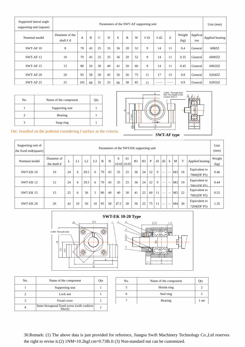
supporting unit (square) Parameters of the SWT-AF supporting unit Unit (mm)
Nominal model Diameter of the
shaft ¢ d A B C D E R W ¢ d1 ¢ d2 Z
Weight
(kg)
Applicat
ion Applied bearing
SWT-AF 10 8 70 43 25 35 36 20 52 9 14 11 0.4 General 608ZZ
SWT-AF 12 10 70 43 25 35 36 20 52 9 14 11 0.35 General 6000ZZ
SWT-AF 15 15 80 50 30 40 41 20 60 9 14 11 0.45 General 6002ZZ
SWT-AF 20 20 95 58 30 45 56 26 75 11 17 15 0.8 General 6204ZZ
SWT-AF 25 25 105 68 35 25 66 30 85 11 —— —— 0.9 General 6205ZZ
No. Name of the component Qty
1 Supporting seat 1
2 Bearing 1
3 Snap ring 1
Supporting unit of
the fixed end(square) Parameters of the SWT-EK supporting unit
Unit
(mm)
Nominal model Diameter of
the shaft d L L1 L2 L3 B H
b
±0.02
h1
±0.02 B1 H1 P d1 d2 h M T Applied bearing
Weight
(kg)
SWT-EK 10 10 24 6 29.5 6 70 43 35 25 36 24 52 9 — — M3 16 Equivalent to
7000(DF P5) 0.46
SWT-EK 12 12 24 6 29.5 6 70 43 35 25 36 24 52 9 — — M3 19 Equivalent to
7001(DF P5) 0.44
SWT-EK 15 15 25 6 36 5 80 49 40 30 41 25 60 11 — — M3 22 Equivalent to
7002(DF P5) 0.55
SWT-EK 20 20 42 10 50 10 95 58 47.5 30 56 25 75 11 — — M4 30 Equivalent to
7204(DF P5) 1.35
No. Name of the component Qty
5 Shrink-ring 2
6 Seal ring 2
7 Bearing 1 set
No. Name of the component Qty
1 Supporting seat 1
2 Lock nut 1
3 Fixed cover 1
4 Inner hexagonal fixed screw (with cushion
block) 1
Ote: Installed on the pedestal considering I surface as the criteria. SWT-AF type
SWT-EK 10-20 Type
30.Remark: (1) The above data is just provided for reference, Jiangsu Swift Machinery Technology Co.,Ltd reserves
the right to revise it.(2) 1NM=10.2kgf.cm=0.73Ib.ft (3) Non-standard nut can be customized.
2-Ød1 Through-hole Ød2 The depth of the counter bore Z
2-Ød1 Through-hole

Fixed lateral
angle
supporting unit
(square))
Parameters of the SWT-AK supporting unit
Weight
(kg)
Thread section
of lock nut M
Bearing of
the auxiliary
supporting
end Nominal model
Application
¢d A B C D E F L J K N Size of the counter bore
H P Q W X Y Z
SWT-AK10 Genera
l 10 70 43 25 35 36 17 24 30 5.5 6 12 —— —— 52 9 14 11 0.5 M10×1 608ZZ
SWT-AK12 Genera
l 12 70 43 25 35 36 19 24 30 5.5 6 12 —— —— 52 9 14 11 0.5 M12×1 6000ZZ
SWT-AK15 Genera
l 15 80 50 30 40 41 22 25 31 12 5 12.5 —— —— 60 11 17 15 0.7 M15×1 6002ZZ
SWT-AK20 Genera
l 20 95 58 30 45 56 30 42 52 10 10 —— 22 10 75 11 17 15 1.4 M20×1 6204ZZ
SWT-AK25 Genera
l 25 105 68 35 25 66 36 45 61 13 14 —— 30 9 85 11 — — 1.9 M25×1.5 6205ZZ
Nominal model
Tightening torque for reference (N * cm)
Lock nut Positioning and snap
screw
SWT-AK 10 280 147 (M4)
SWT-AK 12 630 147 (M4)
SWT-AK 15 790 147 (M4)
SWT-AK 20 1670 147 (M4)
SWT-AK 25 2060 490 ( M6 )
Components of the supporting unit
S direction Press cover
Snap screw
Positioning
block
S direction (SWT-AK10-15) S direction (SWT-AK20-25)
2-ØX Through-hole 2-ØX Through-hole
ØY The depth of the counter bore Z ØY The depth of the
counter bore Z
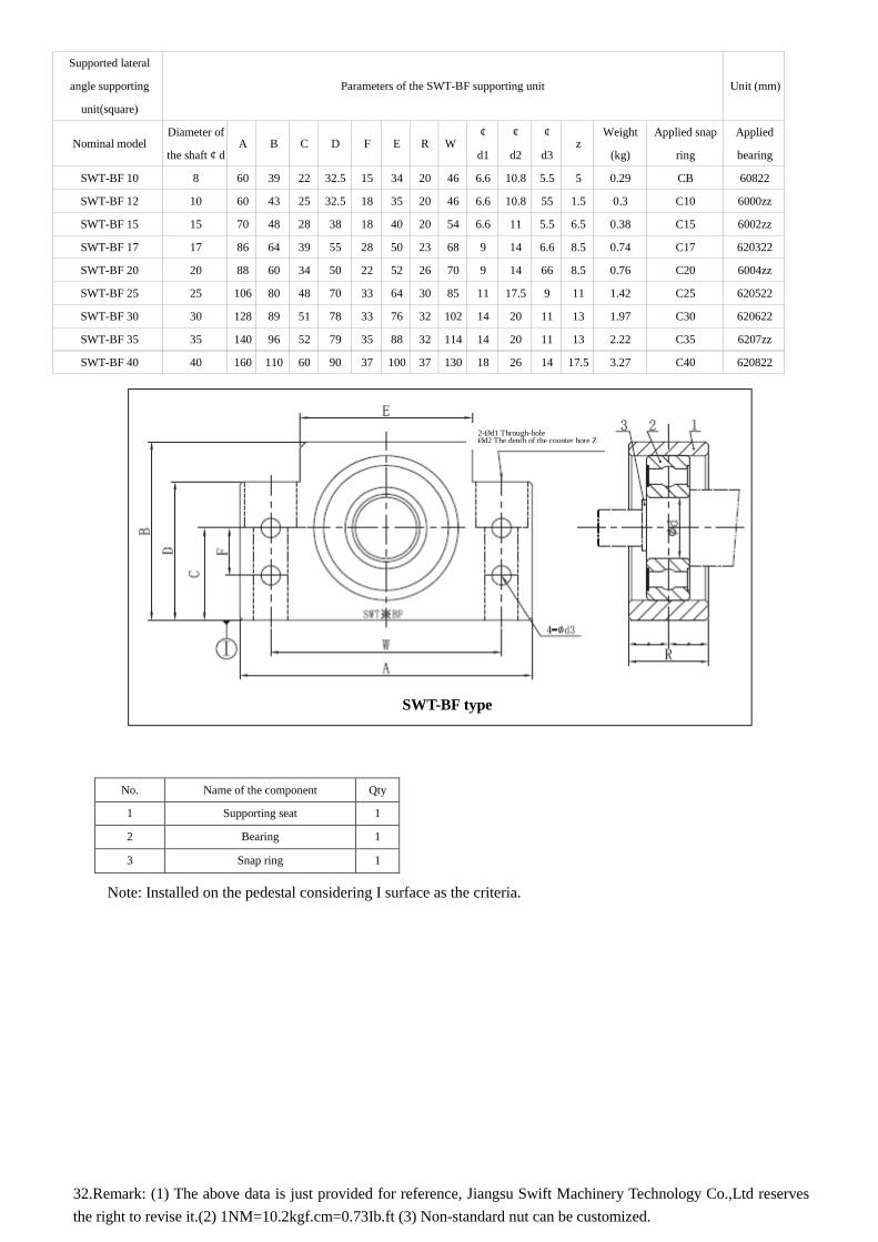
Supported lateral
angle supporting
unit(square)
Parameters of the SWT-BF supporting unit Unit (mm)
Nominal model Diameter of
the shaft ¢ d A B C D F E R W
¢ ¢ ¢ z
Weight
(kg)
Applied snap
ring
Applied
bearing d1 d2 d3
SWT-BF 10 8 60 39 22 32.5 15 34 20 46 6.6 10.8 5.5 5 0.29 CB 60822
SWT-BF 12 10 60 43 25 32.5 18 35 20 46 6.6 10.8 55 1.5 0.3 C10 6000zz
SWT-BF 15 15 70 48 28 38 18 40 20 54 6.6 11 5.5 6.5 0.38 C15 6002zz
SWT-BF 17 17 86 64 39 55 28 50 23 68 9 14 6.6 8.5 0.74 C17 620322
SWT-BF 20 20 88 60 34 50 22 52 26 70 9 14 66 8.5 0.76 C20 6004zz
SWT-BF 25 25 106 80 48 70 33 64 30 85 11 17.5 9 11 1.42 C25 620522
SWT-BF 30 30 128 89 51 78 33 76 32 102 14 20 11 13 1.97 C30 620622
SWT-BF 35 35 140 96 52 79 35 88 32 114 14 20 11 13 2.22 C35 6207zz
SWT-BF 40 40 160 110 60 90 37 100 37 130 18 26 14 17.5 3.27 C40 620822
Note: Installed on the pedestal considering I surface as the criteria.
No. Name of the component Qty
1 Supporting seat 1
2 Bearing 1
3 Snap ring 1
32.Remark: (1) The above data is just provided for reference, Jiangsu Swift Machinery Technology Co.,Ltd reserves
the right to revise it.(2) 1NM=10.2kgf.cm=0.73Ib.ft (3) Non-standard nut can be customized.
SWT-BF type
2-Ød1 Through-hole Ød2 The depth of the counter bore Z

Fixed lateral
angle supporting
unit (square) Parameters of the SWT-BK supporting unit
Unit
(mm)
Nominal model Diameter of
the shaft H H1 h1 B P b B1 M ¢ ¢ ¢ Z L L1 L2 L3 C1 C2
Applie
d
Weight
(kg)
¢ d H H1 ±0.02 B p ±0.02 B1 M d1 d2 d3 z L L1 L2 L3 C1 C2
bearing
Weight
(kg)
SWT-BK 10 10 39 32.5 22 60 46 30 34 M3 6.6 10.8 5.5 5 25 5 29 5 13 6 7000 0.39
SWT-BK 12 12 43 32 5 25 60 46 30 35 M3 6.6 10.8 55 1.5 25 5 29 5 13 6 7001 0.41
SWT-BK 15 15 48 38 28 70 54 35 40 M3 6.6 11 5.5 6.5 27 6 32 6 15 6 7002 0.57
SWT-BK 17 17 64 55 39 86 68 43 50 M4 9 14 6.6 8.5 35 9 44 7 19 8 7203 1.27
SWT-BK 20 20 60 50 34 88 70 44 52 M4 9 14 66 8.5 35 8 43 8 19 8 7004 1.19
SWT-BK 25 25 80 70 48 106 85 53 64 M5 11 17.5 9 11 42 12 54 9 22 10 7205 2.3
SWT-BK 30 30 89 78 51 128 102 64 76 M6 14 20 11 13 45 14 61 9 23 11 7206 3.32
SWT-BK 35 35 96 79 52 140 114 70 88 MS 14 20 11 13 50 14 67 12 26 12 7207 4.33
SWT-BK 40 40 110 90 60 160 130 80 100 MS 18 26 14 17.5 61 18 76 15 33 14 7208 6.5
Note: Installed on the pedestal considering I surface as the criteria.
No. Name of the component Qty
1 Supporting seat 1
2 Lock nut 1
3 Fixed cover 1
4 Inner hexagonal fixed screw (with cushion block) 1
5 Shrink-ring 2
6 Seal ring 2
7 Bearing 1 set
SWT-BK type
4-Ød1 Through-hole Ød2 The depth of the counter bore Z
4-Ød3 Through-hole
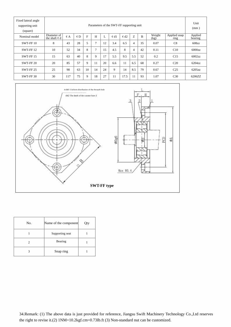
Fixed lateral angle
supporting unit
(square)
Parameters of the SWT-FF supporting unit Unit
(mm )
Nominal model Diameter of the shaft ¢ d
¢ A ¢ D F H L ¢ d1 ¢ d2 Z B Weight (kg)
Applied snap ring
Applied bearing
SWT-FF 10 8 43 28 5 7 12 3.4 6.5 4 35 0.07 C8 608zz
SWT-FF 12 10 52 34 8 7 15 4.5 8 4 42 0.11 C10 6000zz
SWT-FF 15 15 63 40 8 9 17 5.5 9.5 5.5 52 0.2 C15 6002zz
SWT-FF 20 20 85 57 9 11 20 6.6 11 6.5 68 0.27 C20 6204zz
SWT-FF 25 25 98 63 10 14 24 9 14 8.5 79 0.67 C25 6205zz
SWT-FF 30 30 117 75 9 18 27 11 17.5 11 93 1.07 C30 6206ZZ
No. Name of the component Qty
1 Supporting seat 1
2 Bearing
1
3 Snap ring 1
34.Remark: (1) The above data is just provided for reference, Jiangsu Swift Machinery Technology Co.,Ltd reserves
the right to revise it.(2) 1NM=10.2kgf.cm=0.73Ib.ft (3) Non-standard nut can be customized.
SWT-FF type
4-Ød1 Uniform distribution of the through hole
Ød2 The depth of the counter bore Z

Fixed lateral angle supporting unit
(square) Parameters of the SWT-FK supporting unit
Unit
(mm )
Nominal model Diameter
of the shaft ¢ d
¢ A ¢ D F H L ¢ d1 ¢ d2 Z B T1 Applied bearing
Weight (kg
SWT-FK10 10 52 34 17 10 27 4.5 8 4 42 5 7000 0.21
SWT-FK 12 12 54 36 17 10 27 4.5 8 4 44 5 7001 0.22
SWT-FK 15 15 63 40 17 15 32 5.5 9.5 6 52 6 7002 0.39
SWT-FK 20 20 85 57 30 22 52 6.6 11 10 68 10 7204 1.09
SWT-FK 25 25 98 63 30 27 57 9 15 13 79 10 7205 1.49
SWT-FK 30 30 117 75 32 30 62 11 17.5 15 93 12 7206 2.32
No. Name of the component Qty
1 Supporting seat 1
2 Bearing 1 set
3 Fixed cover 1
4 Shrink-ring 2
5 Seal ring 2
6 Lock nut 1
7 Inner hexagonal fixed screw(with plug copper) 1
SWT-FK type
4-Ød1 Through-hole Ød2 The depth of the counter bore Z

Tel: 0513-86222928 Fax: 0513-85650761 E-mail: [email protected] Website: www.ntswift.com
No.8 Gongyuan Road, Xuzhuang Village, Xingren Town, Tongzhou District, Nantong City, Jiangsu Province