practice note 21 · 2013. 11. 26. · ii pri 21 ar i onds, version 2 march 2013 practice note...
TRANSCRIPT

Farm Dairy Effluent Pond Design and Construction
Practice Note 21ISSN 1176–0907
Version 2, March 2013

iPractice Note 21: Farm Dairy Effluent Ponds, Version 2 March 2013
PrefaceThis Practice Note has an intentional engineering focus on the design and construction of Farm Dairy
Effluent (FDE) ponds as other aspects of the effluent management system are covered by other industry
documents.
While this Practice Note specifically refers to FDE, there are other agricultural industries that produce
effluent that may benefit from it.
The costs of commercially supplied fertilisers are high and likely to climb higher. This Practice Note
introduces a commercial incentive for farmers to apply effluent to pasture in a way that assists with
nutrient retention in the root zone and provides a partial substitution for commercial fertiliser. Storage
enables farmers to target when FDE is applied and thereby gain benefit from recycling nutrients back
to the farm.
Key Points
▪ This Practice Note has been produced to provide a good-practice industry standard for designing and constructing FDE ponds.
▪ Poor-quality ponds adversely affect the environment.
▪ Stored effluent is a valuable source of nutrients for plants and can offset fertiliser costs.
▪ The farmer/owner is ultimately liable for breaches of the Resource Management Act (RMA) and the Building Act (BA) and should seek and be able to rely on sound professional advice to ensure compliance.

ii Practice Note 21: Farm Dairy Effluent Ponds, Version 2 March 2013
Practice note Development The Institution of Professional Engineers (IPENZ), with support from principal sponsors DairyNZ, has
brought together a group of professionals from civil, geotechnical, agricultural, and environmental
engineering back-grounds to develop a Practice Note on the design and construction of FDE ponds.
Formation of the group in early 2011 was initiated by:
▪ Growing concerns expressed by both IPENZ Members and farmers on the poor quality of FDE ponds being designed and constructed in New Zealand
▪ The impact that poor-quality FDE ponds are having on the environment
▪ Identification that regulatory requirements under the Building Code are not being understood by some authorities
▪ Lack of clear definition around who may sign off for FDE ponds and structures
▪ Recognition by IPENZ and DairyNZ for the need to set industry standards for FDE pond design and construction.
The IPENZ Engineering Practice Advisory Committee (EPAC) has given the authors the task of preparing
a document that reflects a national perspective to be adopted by the dairy engineering industry. The
Practice Note has been prepared in accordance with standard IPENZ Practice Note procedures. This
includes reporting on progress to EPAC, peer review and general Membership review. This review and
reporting process ensures the delivery of a robust, good-practice, technical document.
The Practice Note’s intent is to provide good-practice guidelines for professional engineers and other
technical specialists who are involved in the design and construction of FDE ponds. This Practice Note
is also intended to be a good-practice reference source for Regional Council (RC) and Local Authority
(LA) staff, agriculturists, product suppliers, contractors, and others involved in the FDE pond industry.
In addition, the authors have reviewed New Zealand legislation and regulations and sought to interpret
these as they relate to FDE ponds and structures.
To maintain an up to date and industry relevant document, Practice Note 21 underwent a review in late
2012 and three new parts were added: clay liners, geomembrane (synthetic liner) selection, and ponds
and tanks on peat.
DairyNZ continues to raise the profile of effluent management in New Zealand. Their FDE Design Code
of Practice and the FDE Design Standards provide generic guidance for the design and development of
effluent management systems. This distinctly separate Practice Note complements these documents.
In designing FDE pond systems, several other documents may need to be referred to and the references
section links to a number of relevant publications.
While the authors have made every effort to present a carefully considered Practice Note based on
their own professional practice, as well as consultation with the wider industry, they accept that what
constitutes good practice may alter over time following changes in knowledge, technology, and legislation.
They also acknowledge that differing interpretations of relevant legislation and regulations are possible
and that each practitioner will need to confirm with the relevant authorities as to their requirements.

iiiPractice Note 21: Farm Dairy Effluent Ponds, Version 2 March 2013
ContentsPreface ............................................................................................................................................... iPractice Note DeveloPmeNt ........................................................................................................... iiGlossary ........................................................................................................................................ viii
Part 1: Design and Construction Principles1.0 introDuCtion 3
1.1 fDe maNaGemeNt .................................................................................................................31.2 fDe PoNDs ............................................................................................................................31.3 tyPes of fDe PoNDs ............................................................................................................3
2.0 BaCKgrounD 4
2.1 WHat is GooD Practice? .....................................................................................................42.2 WHy are fDe PoNDs Necessary? ........................................................................................42.3 roles aND resPoNsiBilities ...............................................................................................5
3.0 LegisLation anD reguLations 6
3.1 iNtroDUctioN ........................................................................................................................63.2 HealtH aND safety iN emPloymeNt act ...............................................................................63.3 resoUrce maNaGemeNt act ...............................................................................................93.4 BUilDiNG act ..................................................................................................................... 103.5 Historic Places act .......................................................................................................... 163.6 reGUlatory reQUiremeNts overvieW .............................................................................. 17
4.0 site inVestigations 20
4.1 iNvestiGatioN PUrPose: aN overvieW .............................................................................. 204.2 soil ProPerties ................................................................................................................ 204.3 sitiNG a NeW PoND ........................................................................................................... 214.4 fielD iNvestiGatioN stePs ................................................................................................ 23
5.0 Design 25
5.1 iNtroDUctioN .................................................................................................................... 255.2 tyPes of PoNDs ................................................................................................................. 255.3 efflUeNt treatmeNt DesiGN ............................................................................................. 255.4 soliDs maNaGemeNt ......................................................................................................... 265.5 efflUeNt irriGatioN ......................................................................................................... 275.6 PoND siZiNG ...................................................................................................................... 295.7 PoND Geometric DesiGN .................................................................................................. 315.8 soliDs maNaGemeNt DesiGN ............................................................................................ 335.9 liNers ................................................................................................................................ 345.10 PoND PerformaNce coNsiDeratioNs ............................................................................. 35
iv Practice Note 21: Farm Dairy Effluent Ponds, Version 2 March 2013
6.0 ConstruCtion 37
6.1 iNtroDUctioN ..................................................................................................................... 376.2 DraWiNGs aND sPecificatioNs ........................................................................................ 376.3 tHe sUPervisiNG eNGiNeer’s role .................................................................................. 376.4 effects of WorKs oN otHers ......................................................................................... 386.5 UNDerGroUND services .................................................................................................. 386.6 DraiNaGe coNtrol ........................................................................................................... 386.7 coNstrUctioN eQUiPmeNt ................................................................................................ 396.8 comPactioN ....................................................................................................................... 406.9 eXPoseD Batters .............................................................................................................. 426.10 feNces aND Gates ............................................................................................................ 436.11 Practical comPletioN aND Defects liaBility certificates ........................................... 43
7.0 CertifiCation 44
7.1 iNtroDUctioN ..................................................................................................................... 447.2 certificatioN UNDer tHe rma By reGioNal coUNcils .................................................... 457.3 certificatioN UNDer tHe BUilDiNG act ........................................................................... 457.4 certificatioN By coNstrUctioN coNtractor ................................................................. 467.5 certificatioN for PoND DesiGN aND coNstrUctioN revieW ........................................ 47
8.0 oPeration anD MaintenanCe 49
8.1 iNtroDUctioN .................................................................................................................... 498.2 as-BUilt PlaNs .................................................................................................................. 498.3 oPeratioN maNUal ........................................................................................................... 498.4 iNsPectioNs ....................................................................................................................... 498.5 PoND moNitoriNG ............................................................................................................. 508.6 leaKaGe DetectioN aND resPoNse .................................................................................. 508.7 DroP test .......................................................................................................................... 518.8 system oPeratioN ............................................................................................................ 518.9 eXistiNG fDe PoNDs .......................................................................................................... 52
9.0 forMs of ContraCt 53
9.1 scoPe of WorK aND PractitioNer eNGaGemeNt ............................................................ 539.2 etHics ................................................................................................................................ 539.3 coNtractor selectioN .................................................................................................... 549.4 coNtractor eNGaGemeNt ................................................................................................ 559.5 NZs 4431 (coDe of Practice for eartH fill for resiDeNtial DeveloPmeNt) ............. 56

vPractice Note 21: Farm Dairy Effluent Ponds, Version 2 March 2013
Part 2: CLay Liners for PonDs1.0 introDuCtion 59
1.1 iNtroDUctioN ..................................................................................................................... 59
2.0 Design CaLCuLations 60
2.1 HyDraUlic coNDUctivity.................................................................................................... 602.2 seePaGe calcUlatioN ........................................................................................................ 602.3 floW aND seePaGe WitH varyiNG HyDraUlic coNDUctivity ............................................. 61
3.0 inVestigation anD testing 63
3.1 iNvestiGatioN ..................................................................................................................... 633.2 laBoratory testiNG ........................................................................................................... 63
4.0 Liner Design 71
4.1 sloPe aNGles ..................................................................................................................... 714.2 tHicKNess of liNer ........................................................................................................... 724.3 In sItu clay PoNDs ............................................................................................................ 724.4 clay liNer ProtectioN ....................................................................................................... 724.5 UNDer DraiNaGe ................................................................................................................ 734.6 soil treatmeNt UsiNG BeNtoNite ..................................................................................... 74
5.0 ConstruCtion MethoDoLogy 76
5.1 comPactioN eQUiPmeNt .................................................................................................... 765.2 coNtrol of Water ............................................................................................................. 77
6.0 QuaLity assuranCe 78
6.1 comPactioN trial ............................................................................................................... 786.2 site testiNG ........................................................................................................................ 786.3 seePaGe testiNG................................................................................................................. 796.4 recorDs aND siGN-offs .................................................................................................. 80
vi Practice Note 21: Farm Dairy Effluent Ponds, Version 2 March 2013
Part 3: geoMeMBrane (synthetiC Liner) seLeCtion1.0 introDuCtion 85
1.1 iNtroDUctioN ..................................................................................................................... 85
2.0 geoMeMBranes 87
2.1 tyPes of GeomemBraNes ................................................................................................ 872.2 GeosyNtHetic researcH iNstitUte (Gri) sPecificatioNs ............................................... 872.3 GeomemBraNe selectioN By attriBUtes ......................................................................... 90
3.0 instaLLation 92
3.1 eXPerieNceD iNstallers .................................................................................................. 923.2 sUBGraDe PreParatioN .................................................................................................... 923.3 aNcHor treNcHes ............................................................................................................. 923.4 GeosyNtHetic clay liNer (Gcl) ......................................................................................... 933.5 safety ................................................................................................................................. 933.6 GroUNDWater aND DraiNaGe ........................................................................................... 933.7 Gas veNtiNG ....................................................................................................................... 933.8 DraiNaGe aND veNtiNG system DesiGN ............................................................................ 943.9 PeNetratioNs .................................................................................................................... 943.10 stirrers ............................................................................................................................. 943.11 QUality assUraNce aND WarraNties ............................................................................... 95
4.0 suMMary 96
Part 4: PonDs anD tanKs on Peat1.0 introDuCtion 99
1.1 PUrPose ............................................................................................................................. 991.2 WHat is Peat? ...................................................................................................................1001.3 WHy is Peat a cHalleNGe? ..............................................................................................101
2.0 engineering ProPerties of Peat 103
2.1 eNGiNeeriNG issUes WitH coNstrUctioN oN Peat ........................................................1032.2 BeariNG caPacity failUre ...............................................................................................1032.3 eXcessive settlemeNt .....................................................................................................1042.4 sHalloW GroUNDWater taBle ........................................................................................1052.5 Gas collectioN ...............................................................................................................106
3.0 settLeMent 107
3.1 maNaGiNG settlemeNt ....................................................................................................1073.2 PoND BaNK settlemeNt ...................................................................................................1083.3 taNK settlemeNt ..............................................................................................................1093.4 settlemeNt DUriNG Use ..................................................................................................109

viiPractice Note 21: Farm Dairy Effluent Ponds, Version 2 March 2013
4.0 grounD inVestigation, DePths anD MethoDs 110
4.1 scoPe of iNvestiGatioN .................................................................................................1104.2 DePtH of iNvestiGatioN ..................................................................................................1104.3 metHoDs ...........................................................................................................................111
5.0 Design ProCess anD ConsiDerations 114
5.1 cost aND risK assessmeNt ............................................................................................1145.2 DesiGN Process stePs ...................................................................................................115
6.0 suMMary 116
7.0 aCKnowLeDgeMents 117
referenCesreferenCes 121
overvieW .......................................................................................................................................121Part 1: DesiGN aND coNstrUctioN PriNciPles ..........................................................................121Part 2: clay liNers for PoNDs ...................................................................................................125Part 3: GeomemBraNe (syNtHetic liNer) selectioN .................................................................125
aPPenDiCesaPPeNDiX a – iPeNZ sHort form aGreemeNt ..............................................................................129aPPeNDiX B1 – form of ProDUcer statemeNt for: DesiGN of farm Dairy efflUeNt PoNDs .....................................................................................131aPPeNDiX B2 – form of ProDUcer statemeNt for: coNstrUctioN revieW of farm Dairy efflUeNt PoNDs.............................................................132aPPeNDiX B3 – form of ProDUcer statemeNt for: coNstrUctioN of farm Dairy efflUeNt PoNDs .........................................................................133aPPeNDiX c – reGUlatory cHecKlist ...........................................................................................134aPPeNDiX D – PoND certificatioN cHecKlist ..............................................................................138

viii Practice Note 21: Farm Dairy Effluent Ponds, Version 2 March 2013
ATSM American Society on Testing and
Materials
BA Building Act 2004
BCA Building Consent Authority
BOD Biochemical Oxygen Demand (a
measure of degradable organic
matter content)
CCL Compacted Clay Liner
CPT Cone Penetrometer Testing
DC District Council
DD Dry Density
PN Practice Note
CPEng Chartered Professional Engineer
DESC Dairy Effluent Storage Calculator
(Massey University and Horizons
Regional Council)
DD/WC Dry Dentsity/Water Content
EPDM Ethylene Propylene Diene
Monomer (Rubber)
ETPract Engineering Technology
Practitioner
FDE Farm Dairy Effluent
Freeboard Volume (or height) above
maximum effluent design level
in pond
GCL Geosynthetic Clay Liner
GRI Geosynthetic Research Institute
HDPE High-Density Polyethylene (Plastic)
HSE Health and Safety in Employment
Act 1992
IANZ International Accreditation
New Zealand
IPENZ Institution of Professional
Engineers New Zealand
LA Local Authority
LDS Leakage Detection System
LL Liquid Limit
LS Linear Shrinkage
MC Moisture Content
MDD Maximum Dry Density (soil)
MBIE Ministry of Business,
Innovation and Employment
NDM Nuclear Density Meter
NZHPT New Zealand Historic Places Trust
NZS New Zealand Standard(s)
OMC Optimum Moisture (water)
Content (soil)
PL Plastic Limit
PI Plasticity Index
Principal Client or farm owner
PS Producer statement
QA Quality Assurance
RA Regional Authority
RC Regional Council
RMA Resource Management Act 1991
SQP Suitably Qualified Person
SV Shear Vane
TA Territorial Authority
UV Ultra Violet
WC Water Content
glossary

Design and Construction
Principles

3Practice Note 21: Farm Dairy Effluent Ponds, Version 2 March 2013
PART 1: Design and Construction Principles
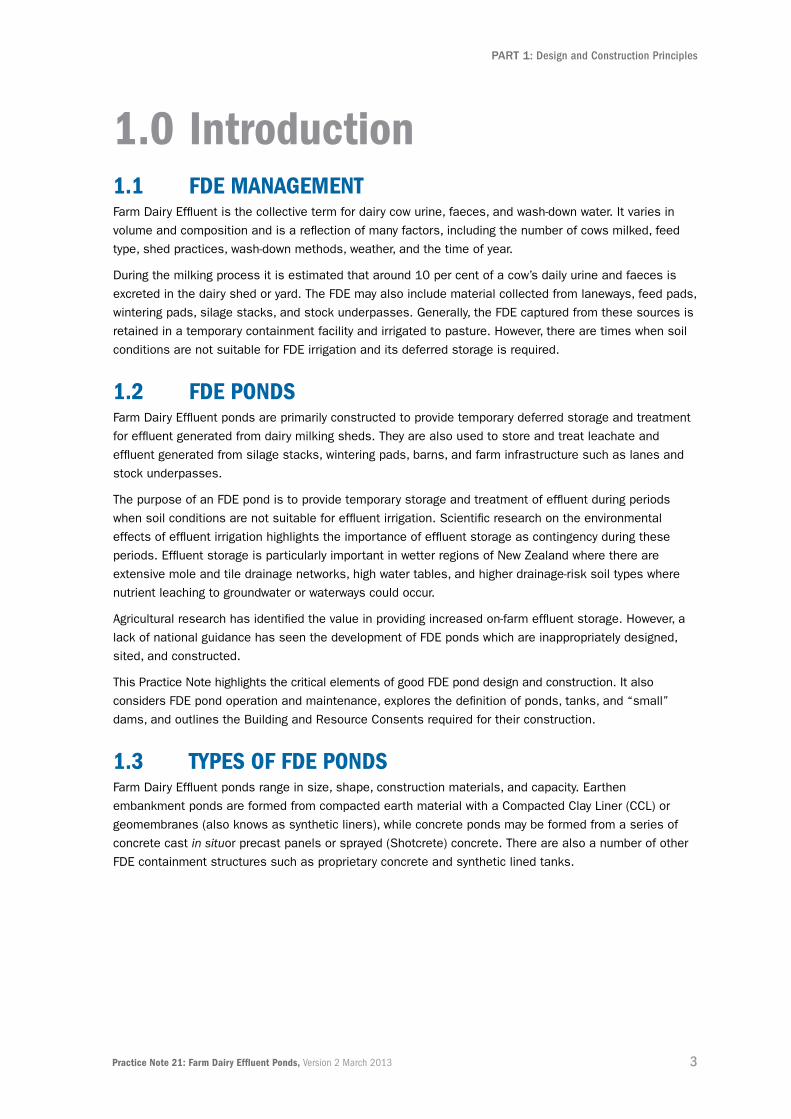
1.0 introduction1.1 fDe ManageMent Farm Dairy Effluent is the collective term for dairy cow urine, faeces, and wash-down water. It varies in
volume and composition and is a reflection of many factors, including the number of cows milked, feed
type, shed practices, wash-down methods, weather, and the time of year.
During the milking process it is estimated that around 10 per cent of a cow’s daily urine and faeces is
excreted in the dairy shed or yard. The FDE may also include material collected from laneways, feed pads,
wintering pads, silage stacks, and stock underpasses. Generally, the FDE captured from these sources is
retained in a temporary containment facility and irrigated to pasture. However, there are times when soil
conditions are not suitable for FDE irrigation and its deferred storage is required.
1.2 fDe PonDs Farm Dairy Effluent ponds are primarily constructed to provide temporary deferred storage and treatment
for effluent generated from dairy milking sheds. They are also used to store and treat leachate and
effluent generated from silage stacks, wintering pads, barns, and farm infrastructure such as lanes and
stock underpasses.
The purpose of an FDE pond is to provide temporary storage and treatment of effluent during periods
when soil conditions are not suitable for effluent irrigation. Scientific research on the environmental
effects of effluent irrigation highlights the importance of effluent storage as contingency during these
periods. Effluent storage is particularly important in wetter regions of New Zealand where there are
extensive mole and tile drainage networks, high water tables, and higher drainage-risk soil types where
nutrient leaching to groundwater or waterways could occur.
Agricultural research has identified the value in providing increased on-farm effluent storage. However, a
lack of national guidance has seen the development of FDE ponds which are inappropriately designed,
sited, and constructed.
This Practice Note highlights the critical elements of good FDE pond design and construction. It also
considers FDE pond operation and maintenance, explores the definition of ponds, tanks, and “small”
dams, and outlines the Building and Resource Consents required for their construction.
1.3 tyPes of fDe PonDs Farm Dairy Effluent ponds range in size, shape, construction materials, and capacity. Earthen
embankment ponds are formed from compacted earth material with a Compacted Clay Liner (CCL) or
geomembranes (also knows as synthetic liners), while concrete ponds may be formed from a series of
concrete cast in situor precast panels or sprayed (Shotcrete) concrete. There are also a number of other
FDE containment structures such as proprietary concrete and synthetic lined tanks.

4 Practice Note 21: Farm Dairy Effluent Ponds, Version 2 March 2013
PART 1: Design and Construction Principles
2.0 Background2.1 what is gooD PraCtiCe? Good practice may be defined as “a level of effort that seeks to meet industry expectations and
typically exceeds minimum compliance requirements”.
To meet the key operational good-practice outcomes, FDE designs must:
▪ Meet RC and BA rules and consent conditions
▪ Include a pond liner of a sufficiently low seepage rate to minimise adverse environmental effects, including infiltration to groundwater
▪ Allow for ongoing operation and maintenance and be appropriately sized for the volume of on-site effluent
▪ Meet its intended use and life span’s durability and serviceability requirements
▪ Provide a clear documentation trail of accountability for the respective suppliers and the components they provided (that is, equipment and products) incorporated into the works.
2.2 why are fDe PonDs neCessary?2.2.1 regionaL CounCiL reQuireMentsRegional councils and unitary authorities impose a range of regulatory requirements on the discharge
of effluent (to air, land, or water). The purpose of these regulations is to avoid, remedy, and mitigate the
adverse effects on the environment.
The requirement for FDE ponds is driven by most councils under the Resource Management Act 1991
(RMA). Aspects of FDE pond construction are also regulated by RCs and District Councils (DCs) under
both the RMA and the BA. There is variability in the regulatory requirements relating to FDE ponds
throughout New Zealand. This creates uncertainty as to standards that are to be applied.
2.2.2 enVironMentaL ProteCtionUsing an FDE pond to process and store effluent enables farmers to manage the effluent’s discharge.
The irrigation method used determines the rate, depth, and evenness of application and therefore the
likelihood of environmental contamination; however, this is outside the scope of this Practice Note.
Regional Councils advocate that good practice is to discharge effluent to land when soil conditions are
appropriate. Appropriate conditions are those where soil moisture is at a sufficiently low level for the
contaminants in the effluent to:
▪ Be utilised by the soil’s biological system
▪ Not move to surface water through overland or subsurface flow
▪ Not infiltrate to groundwater
▪ Any such ponding or run-off has the potential to have adverse effects on the environment, such as excessive nutrients and pathogens entering groundwater and surface waterways.
All FDE structures including ponds, sumps, tanks, dams, as well as the pipes or channels between
them must provide a contained system that prevents FDE leakage.
5Practice Note 21: Farm Dairy Effluent Ponds, Version 2 March 2013
PART 1: Design and Construction Principles
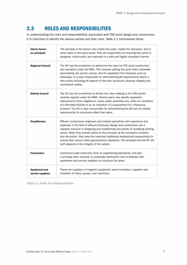
2.3 roLes anD resPonsiBiLities In understanding the roles and responsibilities associated with FDE pond design and construction,
it is important to identify the various parties and their roles. Table 2.1 summarises these.
Client/farmer (or principal)
The principal is the person who meets the costs, makes the decisions, and in most cases is the pond owner. They are responsible for ensuring their pond is designed, constructed, and operated in a safe and legally compliant manner.
Regional Council The RC has the jurisdiction to determine the rules for FDE pond construction and operation under the RMA. This includes setting the pond liner’s allowable permeability, the pond’s volume, and its separation from features such as waterways. It is also responsible for administering BA requirements where a dam exists (including all aspects of the dam structure’s physical integrity and mechanical safety).
District Council The DC has the jurisdiction to dictate the rules relating to the FDE pond’s amenity aspects under the RMA. District plans may specify separation requirements (from neighbours, roads, public amenities etc), either as conditions of a Permitted Activity or as an indication of a requirement for a Resource Consent. The DC is also res-ponsible for administering the BA and its related requirements for structures other than dams.
Practitioners Effluent containment engineers and related specialists with experience and expertise in the field of effluent structures design and construction are a valuable resource in designing and establishing new ponds or modifying existing ponds. While they provide advice to the principal, at the principal’s invitation and dis-cretion, they have the important additional professional responsibility to ensure their advice meets good-practice standards. The principal and the RC will both depend on the integrity of this advice.
Contractors Contractors take instruction from an engineering practitioner, and also a principal when involved, to undertake earthworks and co-ordinate with equipment and service suppliers to construct the pond.
Equipment and service suppliers
These are suppliers of irrigation equipment, pond excavation, suppliers and installers of liners, pumps, and machinery.
Table 2.1: Roles and Responsibilities

6 Practice Note 21: Farm Dairy Effluent Ponds, Version 2 March 2013
PART 1: Design and Construction Principles
3.0 Legislation and regulations 3.1 introDuCtionThis section sets out the legislation and regulations that must be considered when designing and
constructing an FDE pond. While a number of the statutes and regulations relate to design, others
simply relate to the presence of a pond or tank.
The Resource Consent requirements for FDE ponds in New Zealand depend on which RC, DC, or
unitary authority the FDE pond is located within. These organisations are also known as Building
Consent Authorities (BCAs).
The Building Consent requirements required by the BA are intended to be consistently applied across
the country. Even where consent is not needed there is still a requirement to adhere to good design
principles and construction techniques. The Building Code performance requirements and Permitted
Activity standards in regional and district plans must be met and adverse effects on the environment
must be minimised.
3.2 heaLth anD safety in eMPLoyMent aCtThe Health and Safety in Employment Act 1992 (HSE Act) is about the prevention of harm to persons
associated with work. To do this effectively then workplace hazards have to be identified and controlled
effectively. There are duties under the Act on a range of people at work, including designers, suppliers of
plant, principals to contracts, and employers and employees.
HSE requirements will generally relate more to a containment facilities’ on-going operation and its
owners responsibilities, rather than their initial construction, or a facility’s engineering or construction
components.
However, in-ground tanks and ponds need to be specifically designed to address the hazards that they
pose, and in particular systems dealing with FDE which will require a higher standard of ‘safety design’
than for instance systems dealing with clean water.
The employer, who will normally be the containment facility owner, is responsible for protecting people
from mishaps on their worksite. The HSE Act gives the Labour Group within the Ministry of Business,
Innovation and Employment (MBIE), a range of powers to respond to improperly managed hazards.
3.2.1 eLiMination, isoLation or MiniMisation of hazarDsThe HSE Act requires that hazards in the workplace are identified and that all practicable steps are taken
to control them through using a top down hierarchy of control as follows:
▪ Significant hazards (i.e. the hazards that have the potential to cause serious harm or death) must have all practicable steps taken to eliminate the hazard (removed completely).
▪ Where hazards cannot be eliminated, then all practicable steps must be taken to isolate the hazard (physically separated).
▪ Only if there are no practicable means of elimination or isolation available is it acceptable to minimise the hazard (protect employees form harm).

7Practice Note 21: Farm Dairy Effluent Ponds, Version 2 March 2013
PART 1: Design and Construction Principles
This hierarchy of control process for a new FDE system (including ponds and associated plant), would
include the on-going monitoring and assessment of hazards identified during each and every phase,
from investigation and design, through construction, to its operation and maintenance.
Both the designer and the construction supervising engineer have some responsibility for identifying
potential safety issues as part of their design and supervision roles, specifically to eliminate, isolate or
minimise possible hazard risks for items that comprise, or are used, or encountered in the workplace.
3.2.2 fDe PonDs hazarD iDentifiCationFarm Dairy Effluent containment facilities (ponds and tanks) can present two types of significant hazard.
First, an effluent pond may fail causing the released effluent to harm people and the environment. Second,
a person, whether an employee or not, may involuntarily enter a containment facility and suffer harm.
Containment failure hazards are best addressed by farm owners ensuring design and construction is
undertaken with competent advice. It is noted that meeting BA requirements may partly assist with
meeting these and the HSE requirements, but not all HSE requirements can be satisfied solely by
complying with the BA.
A feature of the application of the HSE Act to FDE containment facilities is that no permit is required to
operate, so there is no confirmation of compliance before any mishap. However, a mishap can trigger an
investigation, which can result in punitive action if HSE requirements are found to have not been met.
Should there be an accident involving such a system, then MBIE would be looking at the design of the
pond and related systems ensuring that the HSE Act, and attendant regulations regarding the duties of
designers and suppliers, were being met using “all practicable steps” available. So this could include
considering that although a structure is built ‘safely’, it still needs to be operated with safe practices
or protocols.

8 Practice Note 21: Farm Dairy Effluent Ponds, Version 2 March 2013
PART 1: Design and Construction Principles
3.2.3 hazarD MitigationRegardless of how large the pond is, or the type of lining, it is strongly recommended that all ponds and
other FDE storage facilities have the following Health and Safety related features designed and integrated
into their construction:
Hazard Mitigation around FdE Ponds
Fencing Permanent and secure fencing to prevent stock and children from
accessing FDE pond areas
Gates Lockable access gates
Escape ladders Permanent ladders, or alternative means of escape from ponds
Anchor Points Anchor points to attach floating pontoons to (if used) to improve stability
Signage Hazards on site clearly shown
In addition there needs to be direct communication to farm staff, contractors and visitors about hazards
on the farm. Farm policies and forms can be developed from the DairyNZ Health and Safety Compliance
Toolkit.
www.compliancetoolkit.co.nz/index.asp?pageID=2145868742
3.2.4 fenCing fDe faCiLitiesFencing FDE containment facilities is required under the farm’s health and safety policy. The farm owner
should decide what level of fencing is required based on their HSE risk assessment.
The appropriate type and extent of fencing required for each farm will vary and be dependent on the
hazard risks identified at the site. Where a site contains hazards, which might attract the unauthorized
or unexpected entry of the public, children, or wandering animals (both small and large), then the hazard
needs to be enclosed to restrict access. At the very least, a five wire fence, preferably with netting and
an electric fence ‘hot wire’ should be constructed. In some locations a higher fence such as deer fencing
will be appropriate. Lockable gates and hazard warning signage is strongly recommended.
The Fencing of Swimming Pools Act 1987 requirements do not apply to FDE storage ponds as the ponds
are not intended for swimming.

9Practice Note 21: Farm Dairy Effluent Ponds, Version 2 March 2013
PART 1: Design and Construction Principles
3.3 resourCe ManageMent aCt 3.3.1 fDe anD the resourCe ManageMent aCt Regional Councils are responsible, under the RMA, for FDE ponds. Table 3.1 outlines the relevant RMA
sections.
Section 13 This section places restrictions on certain uses of riverbeds and lakebeds, including dam constructions in riverbeds, or even ephemeral watercourses. In practice, most FDE ponds do not involve damming existing watercourses. This is because they are essentially pits in the ground with no contributing catchment; in these cases Resource Consents for water diversion are unlikely to be required.
Section 14 This section outlines the restrictions relating to water. No person may take, use, dam, or divert water without appropriate plan or consent provision. However, FDE ponds built out of and away from natural watercourses will not involve damming water in the sense intended by the RMA.
Section 15 This section states that no person may discharge any contaminant into water, or onto land, in circumstances which may result in contaminants entering water; unless the discharge is expressly allowed by a rule in a regional plan or Resource Consent.
Note: Agricultural effluent ponds are also administered by some RCs under section 9 of the RMA (restrictions on use of land).
Table 3.1: FDE and the RMA
The term “dam” as used in the RMA, refers to “the action of causing confinement of otherwise
unconfined natural water” (verb). This is different from the use of the term “dam” in the BA which refers
to “a physical structure” (noun).
Regional councils regulate certain aspects of FDE pond construction and operation through their plans
and/or consent process. The primary purpose of this is to protect surface water and groundwater from
potential of FDE contamination.
2,000m3 precast concrete tank.

10 Practice Note 21: Farm Dairy Effluent Ponds, Version 2 March 2013
PART 1: Design and Construction Principles
3.3.2 regionaL CounCiL reQuireMents for fDe PonDsThere is wide variation between regional plan specifications for FDE ponds. Councils often consider
the following in their internal guidance documents:
▪ A pond’s volumetric capacity and slope of batters
▪ The pond liner’s maximum seepage rate at full hydraulic loading
▪ The pond’s spatial separation from bores, wetlands, waterways, and waahi tapu
▪ Design and construction sign-off protocols.
Some RCs require land use consents for ponds. Environment Southland, for example, requires a land
use consent for every FDE containment structure with a capacity >22.5m3. This includes ponds, tanks,
and sumps irrespective of whether they need a Building Consent.
3.3.3 regionaL CounCiL resPonsiBiLities for fDe PonDsThe RMA and regional plan requirements and specifications vary in relation to directing FDE pond
management and construction.
Much of the RC guidance concerns the impact of FDE pond discharges on the environment. The RC
provisions are only legally binding if they are incorporated into a consent and have been accepted by the
parties involved. This differs to requirements in a regional plan which has been through a public process
prior to being adopted, and is therefore legally binding.
The Regulatory Checklist in Appendix C indicates the rule variation between RCs for effluent management
at the time the rules became operative.
3.3.4 DistriCt CounCiL resPonsiBiLitiesSection 31 of the RMA says Territorial Authorities (District Councils) are responsible for controlling the
actual or potential effects of “the use…of land”.
District councils generally view FDE pond construction and operation as a Permitted Activity. This
permission can be given specifically or by default. Separation distances from roads, houses, or property
boundaries are often specified. These may be greater than the separations required by RCs. In some
districts (for example, Horowhenua and Queenstown Lakes District) there are additional limitations on
earthworks where they may compromise visual landscape values.
Under section 9 of the RMA, any land use is permitted unless stated otherwise in a regional or district
plan. Care is needed to ensure FDE ponds are allowed (that is, a Permitted Activity) in the zones involved,
so the regional and district plan should always be consulted for certainty.
The plans may also include performance standards that must be maintained.
3.4 BuiLDing aCt 3.4.1 oVerViewFarm Dairy Effluent can be contained in a variety of structures including tanks, pits, dams, and ponds. It
is therefore important for the FDE system designer to have some understanding of the BA as it relates to
both Building Consent and Building Code requirements.
The BA provides a process for regulating the design and construction of structures and is generally
managed by DCs. However, the requirements for dams are managed by the BCA.

11Practice Note 21: Farm Dairy Effluent Ponds, Version 2 March 2013
PART 1: Design and Construction Principles
The BCA does not require Building Consents in all cases. For containment structures which are
considered to be dams under the BA, the proposed Building Amendment Act (No 4) 2011, Schedule 1,
Part 1, section 22 says “Building work in connection with a dam that is not a large dam” is exempt from
a Building Consent. In general, FDE ponds are covered by this provision and do not generally require
Building Consents.
However, two important BA sections need to be considered when structures (including ponds and tanks)
are constructed or altered.
Section 7 states that building work includes “site work” and “design work relating to building work”.
Therefore, in general terms no site work can be started until a Building Consent (if not exempted) has
been approved for the proposed construction.
Section 17 states “All building work must comply with the Building Code to the extent required by this Act,
whether or not a Building Consent is required in respect of that building work”.Therefore, regardless of
the DC and RC requirement for (or not for) Building Consents, there is still a requirement for structures to
meet the performance requirements of the Building Code.
When this Practice Note was being prepared it became clear that some building regulations are intended
to relate to FDE buildings and structures. However, this is not as clearly expressed and understood as it
could be. As a result, legislation and the resulting building regulations are not being universally applied.
Some DCs are choosing to enforce requirements to “the letter of the law” while other councils seem less
rigid in their interpretation of the regulatory requirements.
Clarification should therefore be sought at an early stage in a project’s development as to the consents
required from the relevant statutory authority.
3.4.2 BuiLDing Consents for tanKs anD PonDsWhile a tank and pool are referenced in the Building Code, they are not defined. While no explicit
definition is made of a “tank” in the BA, it is generally accepted that some effluent structures, for
example concrete-lined ponds, should be classified as tanks. Tanks in the BA context may also refer
to pools, sumps, some ponds, and some other containment structures. Presently Building Consent
requirements under the BA for new tanks and alterations to existing tanks attract varied interpretations
around the country.
A definition for the elements associated with FDE design has not been agreed, so for the purpose of this
Practice Note the following definitions for tanks and ponds associated with agricultural effluent are used.
It should be noted these definitions do not have legal status.
Tank (effluent): is constructed of man-made materials such as concrete, steel, plastic, or milled timber,
or other products; its purpose is to retain and store or collect fluids (including sludge/effluent).
The tank materials are used as the structural elements to retain the fluid. A tank may or may
not have a lid and has essentially vertical sides.
Pond (effluent): is either constructed of compacted soil or rock embankments, or excavated into the
exist-ing ground – or a combination of both these methods – to provide a containment facility
for fluid (including sludge/effluent). Ponds may have a liner installed to seal the pond from
leakage; however, the earthen materials are used to provide the structural elements for
confinement. The internal batters are less than 45 degrees and do not have lids.
12 Practice Note 21: Farm Dairy Effluent Ponds, Version 2 March 2013
PART 1: Design and Construction Principles
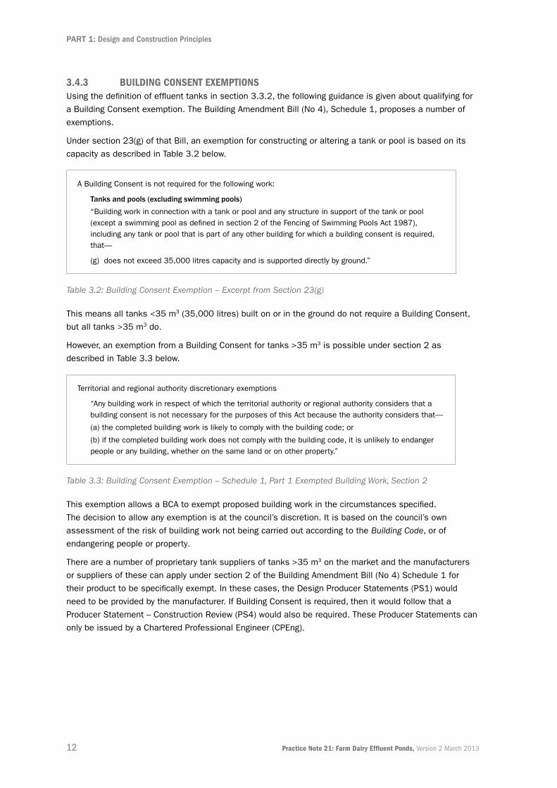
3.4.3 BuiLDing Consent exeMPtionsUsing the definition of effluent tanks in section 3.3.2, the following guidance is given about qualifying for
a Building Consent exemption. The Building Amendment Bill (No 4), Schedule 1, proposes a number of
exemptions.
Under section 23(g) of that Bill, an exemption for constructing or altering a tank or pool is based on its
capacity as described in Table 3.2 below.
A Building Consent is not required for the following work:
Tanks and pools (excluding swimming pools)
“Building work in connection with a tank or pool and any structure in support of the tank or pool (except a swimming pool as defined in section 2 of the Fencing of Swimming Pools Act 1987), including any tank or pool that is part of any other building for which a building consent is required, that—
(g) does not exceed 35,000 litres capacity and is supported directly by ground.”
Table 3.2: Building Consent Exemption – Excerpt from Section 23(g)
This means all tanks <35 m3 (35,000 litres) built on or in the ground do not require a Building Consent,
but all tanks >35 m3 do.
However, an exemption from a Building Consent for tanks >35 m3 is possible under section 2 as
described in Table 3.3 below.
Territorial and regional authority discretionary exemptions
“Any building work in respect of which the territorial authority or regional authority considers that a building consent is not necessary for the purposes of this Act because the authority considers that—
(a) the completed building work is likely to comply with the building code; or
(b) if the completed building work does not comply with the building code, it is unlikely to endanger people or any building, whether on the same land or on other property.”
Table 3.3: Building Consent Exemption – Schedule 1, Part 1 Exempted Building Work, Section 2
This exemption allows a BCA to exempt proposed building work in the circumstances specified.
The decision to allow any exemption is at the council’s discretion. It is based on the council’s own
assessment of the risk of building work not being carried out according to the Building Code, or of
endangering people or property.
There are a number of proprietary tank suppliers of tanks >35 m3 on the market and the manufacturers
or suppliers of these can apply under section 2 of the Building Amendment Bill (No 4) Schedule 1 for
their product to be specifically exempt. In these cases, the Design Producer Statements (PS1) would
need to be provided by the manufacturer. If Building Consent is required, then it would follow that a
Producer Statement – Construction Review (PS4) would also be required. These Producer Statements can
only be issued by a Chartered Professional Engineer (CPEng).

13Practice Note 21: Farm Dairy Effluent Ponds, Version 2 March 2013
PART 1: Design and Construction Principles
3.4.4 DaM reQuireMentsWith respect to the BA, a dam is the physical structure that can hold back water above ground level.
Table 3.4 below provides the legal definition of a dam. This definition is different from the definition of a
pond, which describes the contained liquid. A pond can exist without a dam, in which case the maximum
water level would be below ground level. As soon as the water level rises above the ground surface, the
containment structure is described as a dam. The dam is not the whole containment structure, but only
the physical barrier where the water level exists above ground level.
“A dam —
(a) means an artificial barrier, and its appurtenant structures, that—
(i) is constructed to hold back water or other fluid under constant pressure so as to form a reservoir; and
(ii) is used for the storage, control, or diversion of water or other fluid; and
(b) includes—
(i) a flood control dam; and
(ii) a natural feature that has been significantly modified to function as a dam.”
Table 3.4: Dam Definition, Building Act 2004, section 7
Large dams are those which retain >3 m depth and hold >20,000 m3 of fluid. The Building and Housing
section of MBIE propose that this volume threshold will increase. A legislative amendment is proposed
that will give Regional Authorities (RAs) responsibility for all dams in their region. Given that it would be
rare for an effluent pond to meet the large dam criteria, the additional requirements of these ponds are
not further explored in this Practice Note.
Many ponds are essentially pits in the ground, with the placement and compaction of the cut material
forming an embankment around the pond perimeter. When the pond is filled up to, or lower than, the
lowest elevation of the surrounding ground, no damming will have occurred. However, if the fluid level
rises above the lowest level of the surrounding ground, so the surrounding wall provides a barrier, the
surrounding wall will be functioning as a dam.
Depending on the particular circumstances, some pond-related structures, such as jetties and floating
pon-toon structures, may meet the “appurtenant structure” definition described in the BA. In these cases,
they will be considered to be part of a dam. They are also likely to be considered “building work” so must
comply with the Building Code.
In terms of the BA, dam management is delegated to RCs, rather than DCs. The RCs’ concern focuses on
the potential for the dam structure to fail; and the consequences if they do fail.
Table 3.5 below shows FDE ponds can fall into one of three categories when determining if they are
dams or not. They can be generally described as either “not a dam”, a “dam”, or a “large dam.

14 Practice Note 21: Farm Dairy Effluent Ponds, Version 2 March 2013
PART 1: Design and Construction Principles
not a dam If a pond is constructed by excavating a pit in the ground, and does not have an embankment constructed to allow the fluid to rise to a greater height* than that of the surrounding land, then the pond is not confined. It is therefore not a dam.
dam If the fluid in the pond is confined by an earthen embankment or any other structure in such a way that the fluid in it may rise to a maximum height* of 3 m or the holding capacity of the pond is <20,000 m3, then the pond is confined and is therefore defined by the BA as a dam.
Large dam If the fluid in the pond is confined by an earthen embankment or any other structure in such a way that the fluid in it may rise to a height* >3 m and the volumetric capacity of the pond exceeds 20,000 m3, then the pond is classified as a large dam.
(Note: the definition of a large dam is due to change following the passing of a BA amendment to “large dam means a dam that has a height of 4 or more metres, or holds 20,000 or more cubic metres of water or other fluid”.)
*Height of dam
“the height of a dam is the vertical distance from the top (crest) of the dam and must be measured:
(a) in the case of a dam across a stream, from the natural bed of the stream at the lowest downstream outside limit of the dam; and
(b) in the case of a dam not across a stream, from the lowest elevation at the outside limit of the dam.”
Table 3.5: Categories of FDE Ponds
The BA states that all building work carried out must comply with the Building Regulations 1992 (also
known as the Building Code). Building work includes the construction and alteration of dams even though
they are exempt from requiring a building consent for this work.
The Building Code sets out performance standards that building work must meet, and covers aspects
such as structural stability and durability. The Building Code does not prescribe how building work should
be done (ie, no detailed requirements for design and construction), but states how completed building
work, and its components, must perform. This is important when considering constructing a dam, as each
dam is unique to its location and environment. A dam, however, should be designed and constructed and
maintained in a manner that safeguards people and property from structural failure and throughout its
life continues to comply with the Building Code and have a low probability of failure. Mention is made
again that the dam definition will capture some ponds and sumps.
It is also important to note that while a Building Consent may not be required for a dam, a Resource
Consent may be required for the earthworks associated with its construction.

15Practice Note 21: Farm Dairy Effluent Ponds, Version 2 March 2013
PART 1: Design and Construction Principles
3.4.5 retaining waLLsThe BA’s definition of a retaining wall is interpreted so that if a FDE pond, tank, sump or other retaining
wall structure (e.g. constructed of concrete, steel or timber) is not higher than 1.5 metres and does not
support any load, then it will not require a Building Consent. This decision will probably also depend on
the retaining structure’s construction, function, depth, and geometry.
If a retaining structure of less than 3 metres depth were to be constructed in a rural zone, then it would
may be exempt from the Building Consent requirement. However, this will only be the case if the design
is carried out or reviewed by a CPEng and is not required to support a load, for example, a farm vehicle
or building.
These exemptions for retaining structures are detailed in Sections 20, 22 and 40 of schedule 1 of the
Building Amendment Bill (No 4); refer to Table 3.6 below.
Throughout New Zealand there are a variety of council consent and enforcement requirements for
containment structures. They are best placed to clarify and confirm the specific consent requirements
in their areas.
Part 1 Exempted building work other structures
“(20) Building work in connection with a retaining wall that—
(a) retains not more than 1.5 metres depth of ground; and
(b) does not support any surcharge or any load additional to the load of that ground (for example, the load of vehicles).”
“(22) Dams (excluding large dams)
Building work in connection with a dam that is not a large dam.”
Part 3
Building work for which design is carried out or reviewed by chartered professional engineer
“(40) Building work in connection with a retaining wall in a rural zone, if—
(a) the wall retains not more than 3 metres depth of ground; and
(b) the distance between the wall and any legal boundary or existing building is at least the height of the wall
rural zone means any zone or area (other than a rural residential area) that, in the district plan of the territorial authority in whose district the building work is to be undertaken, is described as a rural zone, rural resource area, or rural environment, or by words of similar meaning.
Table 3.6: Retaining Structures–Building Amendment Bill (No 4) Exemptions

16 Practice Note 21: Farm Dairy Effluent Ponds, Version 2 March 2013
PART 1: Design and Construction Principles
3.4.6 BuiLDing CoDe anD inDustriaL LiQuiD wastes Section G1 of the Building Code does not specifically define FDE as a hazardous material. Nor is it listed
in Table 1 of section G14 as an example of industrial liquid waste.
However, the section on storage facilities (G14.3.2 of the Building Code) does provide some good-practice
considerations when designing FDE ponds (refer to Table 3.7 below).
“Facilities for the storage, treatment, and disposal of industrial liquid waste must be constructed—
(a) with adequate capacity for the volume of waste and the frequency of disposal; and
(b) with adequate vehicle access for collection if required; and
(c) to avoid the likelihood of contamination of any potable water supplies in compliance with Clause G12 “Water supplies”; and
(d) to avoid the likelihood of contamination of soils, groundwater, and waterways except as permitted under the Resource Management Act 1991; and
(e) from materials that are impervious both to the waste for which disposal is required, and to water; and
(f) to avoid the likelihood of blockage and leakage; and
(g) to avoid the likelihood of foul air and gases accumulating within or entering into buildings; and
(h) to avoid the likelihood of unauthorised access by people; and
(i) to permit easy cleaning and maintenance; and
(j) to avoid the likelihood of damage from superimposed loads or normal ground movement; and
(k) if those facilities are buried underground, to resist hydrostatic uplift pressures.”
Table 3.7: Building Code Section G14.3.2: Industrial Liquid Wastes
These considerations pick up several issues which are covered in other design guidance Practice Notes
and Standards, which are crucial for good-practice design. This guidance is available for instance for (a)
pond capacity; (e) leakage and is prescribed by RCs; and (h) safety, which is covered by the Health and
Safety Employment Act 1992 (HSE).
3.5 historiC PLaCes aCtThe Historic Places Act 1993 makes it unlawful to destroy, damage, or modify an archaeological site
without prior authority from the New Zealand Historic Places Trust (NZHPT). This means any work that
may affect an archaeological site requires an authority from the NZHPT before work begins. This may
include road works, quarrying, and any other excavation activities related to pond construction. This is the
case regardless of whether a Resource or Building Consent has been granted.
As part of their district plan, Territorial Authorities (TAs) prepare maps which include heritage and
archaeological sites. These should be checked prior to consent applications being submitted for pond
and related earthworks.
If a previously unknown site is uncovered during earthworks, permission from the NZHPT may be needed
for the work to continue. For further information on investigating archaeological sites, contact NZHPT or
email [email protected]

17Practice Note 21: Farm Dairy Effluent Ponds, Version 2 March 2013
PART 1: Design and Construction Principles
3.6 reguLatory reQuireMents oVerViewThere are potentially four sets of regulatory standards to be met for FDE containment facilities (which
include dams, tanks, sumps, pools, and ponds). Up to three of these may involve consent requirements.
While in most situations dams, tanks, and ponds may be constructed without requiring Building Consent,
Building Code performance compliance is still required. Furthermore, if the FDE pond or tank design and
construction require a Building Consent, then generally only a CPEng has the authority for signing off such
work. Whether this is required depends on the BCA’s policies.
As an overview, Table 3.8 below notes the key regulatory requirements for FDE ponds, while Figure 3.1
outlines consenting and code of compliance requirements. Figure 3.2 provides a schematic regulatory
decision flow diagram to help practitioners understand the consent process. The relevant regulatory
requirements are summarised in a checklist in Appendix C.
aCt or tyPe of LegisLation
PossiBLe reQuireMents reguLatory authority
Resource Management Act 1991
Resource Consent for construction/earthworks (if trigger is exceeded)
Resource consent for use/discharge
Consent for stream diversion
Regional Council
Building Act 2004; Building Code
Consent for construction
Consent for tank
Dam consent
District and Regional Council or unitary authority
Local government requirements (district plan/RMA)
Land use consent
Earthworks/gravel extraction
Local council or unitary authority
Health and Safety in Employment Act 1992
Safety during construction
Fencing of ponds
MBIE (Labour Group) www.dol.govt.nz
Table 3.8: Regulatory Requirements
Key Points
▪ Pond consents required will depend on whether they are: not a dam, a dam, or a large dam.
▪ Regional Council and Building Consent requirements vary within New Zealand.
▪ Tanks may need Building Consents.
▪ Health and safety requirements including fencing and means of escape must be considered.
▪ All ponds must meet the performance requirements of the Building Act.

18 Practice Note 21: Farm Dairy Effluent Ponds, Version 2 March 2013
PART 1: Design and Construction Principles
Figu
re 3
.1: C
onse
ntin
g an
d Cod
e Com
plia
nce
Req
uire
men
ts

19Practice Note 21: Farm Dairy Effluent Ponds, Version 2 March 2013
PART 1: Design and Construction Principles
Figu
re 3
.2: R
egul
ator
y D
ecis
ion
Flow
Dia
gram
20 Practice Note 21: Farm Dairy Effluent Ponds, Version 2 March 2013
PART 1: Design and Construction Principles
4.0 site inVestigations4.1 inVestigation PurPose: an oVerViewSite investigations determine whether, given the site conditions, a structurally sound structure that
meets TA and RC rules can be built.
4.1.1 new PonDsFor new FDE ponds, the proposed site should be thoroughly investigated before design and construction
begins. Generally, an FDE pond should be located in an area with low permeability soils to reduce the risk
of seepage loss.
Soil profile samples should be obtained to provide information on the material properties. These should
be obtained at the depth, and beneath, the bottom of the proposed FDE pond. The prevailing groundwater
regime is also critically important.
4.1.2 existing PonDsAssessing the potential for an existing FDE pond to leak is difficult. However, it may be possible to
see if it is leaking from visual observations and by measuring fluid levels over time, while taking into
account evaporation. Essentially, ponds that show a rapid drop in level over relatively short time periods
will probably be seeping at unacceptable rates and need further assessment. Visual assessments to
determine obvious high-seepage zones (for example, through embankment or conduits) are good starting
points. It would also be prudent to establish whether the existing liner (if present) has been damaged.
These assessments could be followed by verifying the soil profile and characteristics around representative
portions outside the pond using the techniques described below. Associated permeability testing may also
be necessary to confirm the seepage rate of the soil profile, to confirm whether unacceptable seepage is
an issue.
If there is any doubt about a pond leaking and no obvious cause is located, then environmental sampling
and investigation may be required to pinpoint the source and impact of any contamination.
4.2 soiL ProPerties Site investigations must be detailed enough to identify the variations in soil types present at the site.
Early in the investigation the designer needs to consider whether a clay or synthetically lined pond is
most likely required. This will ensure the investigation is more precisely conducted to collect relevant
information.
Clays and silty clays are the most appropriate natural materials for pond construction. In some cases
where sand, gravels, pumice, and other highly permeable soils prevail, the only solution will be a
synthetic lining material or a CCL using suitable imported/borrowed materials. A synthetic lining should
be considered at sites where soils are unlikely to be able to meet the liner permeability requirement
specified by the RC.
The New Zealand Geotechnical Society has a guideline for the field classification and description of soils
and rock (refer to References section).

21Practice Note 21: Farm Dairy Effluent Ponds, Version 2 March 2013
PART 1: Design and Construction Principles
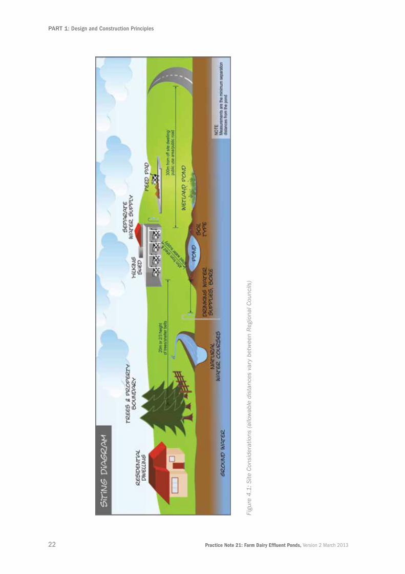
4.3 siting a new PonD It is appropriate to investigate where a pond will be sited and to avoid installing design elements that
allow for the pond’s proximity to sensitive features. These features can include surface water bodies,
artificial watercourses, installed subsurface drains, groundwater level, bores, registered drinking-water
supplies, coastal marine areas, trees, stop banks, residential dwellings, places of assembly, urban areas,
property boundaries, milking areas, and sites of cultural significance. It should be noted that prevailing
winds can carry odour a long way.
Unknown sites of cultural significance are unlikely to be identified before works begin. However, if
discovered during construction, works should cease and the site should be reported immediately to the
NZHPT and local iwi representatives.
Pond placement and orientation should also take into account potential slope instability, inundation
from flooding, diversion of flood flows, and stormwater in-flows. In areas subject to actual or potential
inundation, the pond base should be at least one metre above the highest known flood level if possible.
If not, then specific engineering design should be undertaken. It is also preferable that long ponds be
orientated along the floodplain rather than across it, and perpendicular to the prevailing wind to reduce
the effect on wave action and potential spillage if the pond level is high.
When assessing a site for its suitability for pond construction and the availability of materials the
following factors should be considered:
▪ The type of soil material is present at the site
▪ The soil profile to at least one metre below the finished base depth. How the soil texture may vary down the profile and if there are inherent potential problems due to layering of the materials present. The materials available for bank construction, and/or for lining the inside of the pond
▪ The potential for variation in the soil profile across the pond site
▪ Proximity to natural ground slopes acting as an outer dam embankment wall
▪ Whether the base of the pond is well above the maximum predicted level of groundwater; the slope stability and landforms present.
Other recommendations:
▪ Locate the pond clear of any watercourses, including secondary flow paths; also stream/gully channels
▪ Check the ability to gravity feed the FDE to the pond from the dairy shed rather than needing to pump
▪ Place the site as close as possible to a suitable power source to minimise cost of getting power to the pond if required.
Ponds should be located well clear of trees or shelter belts (about 20 metres or two thirds of the tree
height) to:
▪ Avoid damage to synthetic liners from wind-thrown branches
▪ Minimise debris which would otherwise collect and block pump screens
▪ Avoid ingress of tree roots into the pond walls.
Figure 4.1 provides a graphic showing some site consideration factors.
Another important consideration in some regions is the time of year construction is planned to take
place. While an earthen embankment pond may be very difficult to construct in winter in some regions,
alternative pond systems (for example, precast concrete panelled tanks) can be constructed in winter.
The Ministry of Primary Industries requires dairy to specify certain requirements, such as their effluent
storage facilities’ separation distance from their milking sheds. Designers should ask pond owners
to confirm the industry standards that may affect their containment facilities’ design, placement, and
construction.
22 Practice Note 21: Farm Dairy Effluent Ponds, Version 2 March 2013
PART 1: Design and Construction Principles
Figu
re 4
.1: S
ite C
onsi
dera
tions
(al
low
able
dis
tanc
es v
ary
betw
een
Reg
iona
l Cou
ncils
)

23Practice Note 21: Farm Dairy Effluent Ponds, Version 2 March 2013
PART 1: Design and Construction Principles
4.4 fieLD inVestigation stePs Designers need to arrange for field investigations and prepare site investigation reports. Copies of these
reports may be required by RCs to be included with pond consent applications.
The field investigation steps are described below.
Step 1: Assess and record the site’s overall terrain. Need to note: slope stability, surface water, and
vegetation type. The site should be devoid of trees to avoid the presence of tree roots near
the pond.
Step 2: Undertake the investigation to at least one metre below the finished depth of the pond to
determine the type of soil materials present. This will require using a hydraulic excavator to
dig the investi-gation test pits across the proposed site. Adhere to the MBIE (Labour Group)
requirements for working in and near trenches.
Step 3: Log and photograph the soil materials to determine the type of soil present, its physical
properties, and overall profile. Record any variations to the natural soils materials such as
imported fill containing wood, plastics, or metals as well as any voids created by tree roots or
water erosion, as these may render the site unsuitable. Give special attention to any collapsing
of the test pit sides and its mechanism for failure, as this may be an indicator of substandard
performance for the material type present.
Step 4: Closely assess the soil texture and materials to establish whether a synthetic liner is needed
to be fitted inside of the excavated pond. If the in situ soil itself is intended to be used as a
clay liner then this must be substantiated by testing as outlined in Part 2 (Clay Liners). (Note
that while a soil may have suitable properties to comply with a “sealed pond’s” permeability
requirements, the soil structure and texture ultimately govern its permeability by its preferential
flow paths.)
Step 5: Where a clay liner is considered an option samples of the borrowed material need to be taken
for laboratory testing. It is important none of the samples contain any organic material, so
topsoil must be excluded. Bulk samples should be placed in a labelled, air-tight plastic bag.
Laboratory tests for clay liners are described in Part 2 – section 3.
Step 6: The soil investigation test holes are necessary to assess the level of the water table and
seasonal fluctuations. These fluctuations can be significant and must be determined if the
pond’s floor level is to be set at a safe height. Some sites may have a temporary perched
water table in winter due to impervious subsoil which overlies the main water table. This is
typically indicated by soil discolouration; red-brown indicates oxidised free-draining conditions
while mottled grey indicates lack of internal drainage. Typically dark grey or blue-tinged soils
indicate permanently wet strata.

24 Practice Note 21: Farm Dairy Effluent Ponds, Version 2 March 2013
PART 1: Design and Construction Principles
4.4.1 grounDwaterTest holes in late winter will normally show the highest water table’s location. However, test holes at other
times of the year will require more careful interpretation and a period of monitoring may be required to
obtain reliable data. To monitor the groundwater level, a piezometer can be installed. The groundwater
level can then be measured by dipping a measuring device and recording the depth of the water below
the ground surface.
Local knowledge, if available, should also be considered. In addition, the local RC may have information
on groundwater levels throughout the region, which will be available upon request.
Where there is subsoil, there will usually be indications of fluctuations in the water table in the soil
profile. For profiles without a subsoil (that is, gravels), the water table fluctuations may be more difficult
to establish. The accumulation of iron and manganese, for example, can show the range in water-table
height. They may also show historic high water-table levels which are no longer relevant.
Agricultural land that has typically been artificially drained with tiles and moles, and the presence (or
otherwise) of drainage, may also influence water-table height and allowance must be made for this. Pond
construction must also allow for detecting and removing or replacing tile drains that may be present
under or near the pond structure.
Groundwater monitoring is required to ensure the pond’s proposed base is well above the maximum
predicted groundwater level. It is considered inappropriate to construct ponds below the groundwater
profile. If this must occur, then specific design from a geotechnical professional must be sought.
Key Points
▪ Consider distances from shed, waterways, houses, trees, boundaries, and power source when deciding where to locate ponds.
▪ Site locations need to factor in milk company requirements.
▪ Site investigations must identify all soil types present.
▪ If using compacted clay liners, it is essential to get the clay tested through a professional engineering laboratory.
▪ There is a range of liners and manufactured products available.
▪ Know where the water table and drains are located.
HDPE synthetic liner being installed.

25Practice Note 21: Farm Dairy Effluent Ponds, Version 2 March 2013
PART 1: Design and Construction Principles
5.0 Design5.1 introDuCtion Before any design decisions are made about the pond materials, configuration, and construction,
a clear understanding needs to be reached with the client about:
▪ How the pond fits into the overall FDE system
▪ What type of pond system they require.
There are a number of approaches to managing FDE. Each requires quite different pond designs.
5.2 tyPes of PonDsSome current pond styles include:
▪ A single-pond system, collecting raw effluent. This can provide for moderate settling of the solids (forming a sludge unless stirred) prior to the fluid component being discharged and pumped to a land application area. In many cases the single pond is used for bulk deferred storage with no requirement for settling; it may have a stirrer installed to mobilise the sludge for irrigation to land
▪ A two-pond system involving a typically anaerobic primary pond used for settling solids flowing into a secondary pond which can be aerated to further treat the effluent before it is discharged, or being further clarified (through solids settling or removal), before being discharged
▪ Multi-stage ponds that are similar to wastewater treatment facilities with various settling, clarification, aeration, and disinfection processes prior to the effluent being discharged (typically) to a waterway or land
▪ One- to two-day capacity sumps that collect the raw effluent, which is then discharged via a high-rate travelling irrigator to pasture. These are not considered suitable in some regions to manage effluent and maintain compliance throughout the year.
Current good-management practice is for the construction of deferred irrigation storage ponds, so when
the soil moisture conditions are suitable the effluent can be discharged to land. Otherwise it is stored.
5.3 effLuent treatMent Design5.3.1 anaeroBiC anD aeroBiC PonDsCommonplace treatment in the past was a twin anaerobic/aerobic pond system which usually
discharged to water. However, increasing regulation by most RAs has seen these systems reduce in
number across New Zealand.
Traditionally these ponds have been intended to function as treatment ponds. They maintain a fairly
constant level, with varying seasonal inflow and rainfall, with a related discharge from the pond. Pumping
out and desludging the ponds would be an infrequent occurrence, and the pond would rapidly return
to a normal operating level regardless of whether the intended physical and biological processes were
present.
Where new anaerobic ponds are designed, they should have a normal operating range of >1.5–2.0
metres with a total depth of at least three metres, although four to five metres is ideal. Shallower
treatment ponds (unless mechanically aerated) will be “facultative” with a layer of anaerobic activity on
the base and a thin layer of aerobic water on top.

26 Practice Note 21: Farm Dairy Effluent Ponds, Version 2 March 2013
PART 1: Design and Construction Principles
5.3.2 effLuent PonDs as storageCurrent industry good practice is for the pond to act as a reservoir, providing buffer storage of effluent for
periods (possibly up to six months) when ground conditions do not allow land irrigation. In this mode, the
pond is normally at a low level (possibly empty for long periods through the summer) then filled gradually
during wet weather, but may be drawn down quite rapidly when irrigation is resumed. Earthworks and
lining systems for this type of pond operation need to recognise this fluctuating water-level pattern.
5.4 soLiDs ManageMent5.4.1 soLiDs reMoVaLTraditional FDE irrigation involved pumping directly from the yard or transfer sump (10–30 m3) to pasture.
The sump may have had one or more stirrers to agitate the sump’s entire contents. The resultant slurry
was then applied direct to land via a high-rate travelling irrigator.
Newer FDE systems incorporate a stone trap prior to flow to a large transfer sump (or tank) of 20–140 m3
in size. On days where irrigation is allowed, “raw” FDE is pumped directly to irrigation without separation.
During days where irrigation is not permitted, effluent can either be passed through a solids separation
process (or not) and stored until irrigation is again permitted. The FDE is then either pumped directly from
the pond to irrigate the pasture or returned to the sump for irrigation from there.
If solids are removed before the FDE reaches the storage holding pond, problems with pond solids’
management are reduced or eliminated. Solids removal is commonly achieved by either mechanical or
non-mechanical methods.
5.4.2 MeChaniCaL seParationMechanical separators are typically designed to remove solids down to less than one millimetre. The
resulting liquid contains only fine suspended organic material and silts/clays, plus all the dissolved
nutrient value (these are mainly Nitrogen (N) and Potassium (K). Phosphorus (P) tends to be in the solid
fraction but may also form soluble salts and fine particulates in the effluent).
It is important to be clear about what the principal plans to feed through the mechanical separator and
how this may affect the separator’s performance. In this context, it is also important to consider the
separator’s capacity to ensure it will adequately meet the principal’s current and future needs.
5.4.3 non-MeChaniCaL seParationNon-mechanical separation methods include “weeping walls”, settling ponds, slope screens, and rotating
drum systems.
Recent weeping-wall system developments have improved wall design practice. Good wall design now
includes the following common elements:
▪ Tapered timber or suitably robust plastic or concrete battens with appropriate maximum opening between battens can be used to construct the wall
▪ International guidance has resulted in wall porosities of 15 to 30 per cent to prevent blockages
▪ The wall’s specific engineering design ensures it remains structurally sound when the pond is full
▪ The wall’s large surface area ensures low flow rates and reduces the potential for solids passing through it
▪ The wall’s height is no greater than 2 metres.
Where gravity systems are used, the bottom of the wall is below the storage pond’s maximum fill level.
There are a number of other systems in development which are likely to provide other options to these in
the future.

27Practice Note 21: Farm Dairy Effluent Ponds, Version 2 March 2013
PART 1: Design and Construction Principles
5.5 effLuent irrigation The preferred effluent irrigation method will depend on effluent volume, treatment levels, the terrain to
which the FDE is applied, budgetary constraints, soil properties, and nutrient constraints.
It is not intended that this document go into detail on effluent irrigation, this being covered in the DairyNZ
FDE Design Code of Practice and other publications. However, the following information on effluent
irrigation is provided to give pond designers general awareness on irrigation delivery methods available.
Centre pivot irrigators
A large-area irrigator with prior solids treatment is required. It requires separate piping for effluent and water irrigation, and is most suited to large operations with flat land. The speeds can be altered to apply high and low application rates, and large volumes (>100 m3/hr) can be shifted.
Travelling irrigators
These are large self-propelled wheeled sprinklers with one main drag line. Little treatment is required, as travelling irrigators can generally handle solids well. They typically apply high depth rates. Newer irrigators have been designed to provide lower-depth applications while still having high rates of irrigation. Discharge volumes from 10–100 m3/hr are common.
Pods These are small static sprinklers that require regular moving. There are two main types:
▪ “K-line”, a 4 mm nozzled sprinkler that requires solids removal and many sprinkler heads in a set (20–100+ depending on farm size)
▪ Larger sprinkler heads with 9- to 15-mm nozzles typically in sets of four to five pods perform better with solids removal but are not essential to operation. They are suitable for all terrain. Low-rate application typically <4 mm/hr. Pods have the benefit of pulse application rates, with sets of pods timed for short periods to allow very low average application rates of <1 mm/hr while still achieving volumes discharge requirements.
Guns These large sprinkler heads are similar to raw pods on sprinkler stands and are moved from paddock to paddock. They are connected to preinstalled hydrants or pipework in paddocks. They require frequent moving and can cope with well-treated or raw effluent but need specific setup for each. The guns tend to be forgotten if not electronically monitored, causing over-application. Multiple guns can be connected to a manifold to allow low/pulse application.
Table 5.1: Irrigation Delivery Methods (To Pasture)
Note: If it is intended to connect effluent pipelines to systems primarily intended for water irrigation (for
example, centre pivots), then appropriate risk assessment for back-flow prevention to prevent clean water
supplies being contaminated should be carried out. Ideally, separate pipework should be installed to
eliminate the risk.

28 Practice Note 21: Farm Dairy Effluent Ponds, Version 2 March 2013
PART 1: Design and Construction Principles
The actual irrigation method will have an impact on pond design, with variations depending on the
effluent’s treatment and function. In all cases there will need to be a formed effluent abstraction point,
and all-weather access for an excavator or maintenance vehicles to service or replace pumps etc.
A number of equipment options for FDE intake from a pond can be used and will impact on the
appropriate pond geometry design.
Floating pontoon
The floating pontoon has a pump intake suspended below it with other ancillary equipment (for example, a stirrer) attached. It requires a minimum water level to prevent it running dry. This will affect useable pond sizing, unless a specific pump sump is built in. Access for the pump may be a difficulty. Recent guidance from the MBIE (Labour Group) should be consulted on the appropriate access provisions.
Jetty or structure
The jetty or structure is set into the pond from which the pump and ancillaries can be secured. Health and Safety issues including barriers need consideration. Building Consents will generally be required.
Self-priming pump
The self-priming pump has an intake line into the pond and screen is typically a centrifugal pump requiring low-solids effluent for best performance.
Positive displacement pump
A positive displacement pump which can process higher solids content, such as progressive cavity pumps, can be set up with an intake pipe into the pond with suction screen. Progressive cavity pumps can also be either vertical pontoon mounted or pond crest mounted.
Pump sump A pump sump in the base of the pond with the base sloping down into it will allow maximum draw-down of the pond while allowing pump intakes to remain submerged. It also facilitates easier access for maintenance with flushing or scraping of sludge to the pump-out point.
Table 5.2: Irrigation Intake Options (From Pond)
Sludge bed with double weeping wall and PVC battens.

29Practice Note 21: Farm Dairy Effluent Ponds, Version 2 March 2013
PART 1: Design and Construction Principles
5.6 PonD sizing 5.6.1 DeferreD irrigation storageWhere a pond is being designed as a deferred irrigation storage pond, the size needs to be derived
from a water balance approach to cover the expected “wet year” period when irrigation may not be
allowed due to insufficient soil-moisture deficit to accept the applied effluent which without ponding or
runoff. Guidance should be sought from the RC or best-practice guides as to the return period at which
the calculated maximum annual storage-pond volume required is not to be exceeded.
The size of storage is determined by taking into account a number of factors:
▪ How the principal wishes to manage his FDE
▪ Number of days FDE storage is required (by RC or design standards, whichever is the greater)
▪ Normal daily FDE production volume – some RC’s require a per-cow volume
▪ Rainfall
▪ Soil saturation levels – prevalence of weather conditions and/or soil type where effluent applied would either excessively pond on the soil surface or runoff to surface water, both of which are unlikely to be allowed under Resource Consent conditions
▪ Maximum nutrient loading, as required by Resource Consent, or best practice, or catchment regulations, while allowing for nutrient concentration in effluent
▪ Proposed irrigation method and pumping rate. Low-application irrigation provides a wider window of opportunity to irrigate soils near field capacity, while systems with a high pumping capacity allow more effluent to be irrigated in a short time and therefore the pond volume can be lowered quicker. The daily irrigation volume must be at least double the daily input or the pond is unlikely to be emptied
▪ Expected solids accumulation in the pond
▪ Allowance for the minimum level to which the pump can draw down to (for example, if on a pontoon, it may be best to provide a sump in the pond over which to locate the pump)
▪ Minimum freeboard of 0.5 metres but may need to be greater depending on pond size and prevailing wind conditions
▪ Breakdowns and maintenance contingency allowance
▪ Allowance for future stocking rate (for example, increased herd size, or increased shed utilisation or addition of a feed, standoff, or silage pad).
A water balance model is best calculated by using the Dairy Effluent Storage Calculator (DESC) developed
by Horizons Regional Council and Massey University. It calculates the required stored volume based on a
number of factors including rainfall from the previous 30-year period and soil types. However the following
should be noted:
▪ Local rainfall variability should be taken into account in sizing based on the pond calculator, as coverage of rain-gauge sites in the calculator is limited in some regions, although more will be added with time
▪ The RC will set the rainfall return period, which may be more frequent than one in 30 years
▪ There is currently some variation in the amount of storage that different RC’s require. It is recommended that sizing be based upon a rational assessment of water balance and irrigation application rather than a council minimum storage requirement where the latter gives a lesser volume. This will ensure the installation is future-proofed
▪ The DESC determines pond working storage volume and does not currently allow for freeboard or sludge accumulation volume, but does allow for a specific number of days of “emergency storage” to be added.

30 Practice Note 21: Farm Dairy Effluent Ponds, Version 2 March 2013
PART 1: Design and Construction Principles
5.6.2 retention tiMeWhere ponds are being designed as a treatment component with normal constant level and daily liquid
removal, then sizing will be based on retention time. Additional ponds or capacity are included separately
for the deferred irrigation requirement.
For solids removal, allowance needs to be provided for sludge accumulation. Around 1.5–7 per cent of the
shed effluent may be solids (again a highly variable figure depending upon water use, feed, and season).
Feed pads will be different again, as there tends to be a larger solids component due to feed wastage
(15–45 per cent).
Allowance should also be made for the time interval between solids removal with timing of this in line
with the farm management and seasonal work load. Above the sludge storage allowance will be the liquid
volume required to achieve settling. In effect, the treatment pond is being designed as a rudimentary
clarifier and normal surface-loading rate considerations would apply.
For oxidation or aerated ponds the sizing will be provided by the treatment process designer and is not
within the scope of this Practice Note.
5.6.3 effLuent ProDuCtion ratesPer-cow effluent production figures should be used with caution. They will vary widely from site to
site depending on milking times, shed type, stock handling, feed, season, and wash-down methods.
While a “typical figure” of 50–70 litres/cow/day is often quoted for dairy shed effluent, water efficient
installations may use much less (30 litres/cow/day) and poorly set-up sheds may use in excess of 90
litres/cow/day.
To confirm the design FDE volumes, for example, from the DESC, are consistent with the actual volumes
it is sensible to measure the actual production (in dry weather). This may be possible by measuring the
input water to the shed over milking (watch for milk chiller water as this should not be feeding into the
effluent), plus an allowance of about 10 per cent for urine and faeces. Alternatively, measure the effluent
being pumped away. Allowance should be made for shed upgrades that change the herd size or water
management regime of the shed.
For a new farm/conversion, typical figures will need to be relied on. It is suggested that designers seek
input from the milking plant installer, especially when green water reuse systems are to be installed.
IPENZ promotes good-practice guidelines for water conservation and use.

31Practice Note 21: Farm Dairy Effluent Ponds, Version 2 March 2013
PART 1: Design and Construction Principles
5.7 PonD geoMetriC Design 5.7.1 geoMetry While there are no specific requirements for storage geometry, the pond’s operation and use will govern
its shape. For treatment and settling ponds in general, a long pond with a set width will be better as it
will be easier to clean and provides a longer path for the solids to settle out. A 2:1 length to width ratio
is often used. Consideration should also be given to access for solids removal. The width of the pond
will be determined by what equipment will be used to carry out solids removal. Likewise, the depth is
constrained by desludging equipment, unless specific ramp access is incorporated into the design.
Where a pond containing unprocessed FDE is to be stirred prior to pumping, a round pond would be
preferable. However, we suggest making contact with the stirrer supplier to ensure that the pond can be
effectively stirred given the proposed pond size.
A long and narrow deferred storage pond should be orientated to avoid the longest dimension being in
the direction of the prevailing wind as wave and wind action may increase risk of wave action damage or
overtopping/splash. It is also preferable to have rounded interior corners rather than sharp changes in
direction which have a higher scouring risk.
DairyNZ has developed a spreadsheet based tool to assist in calculating the working volumes and true
dimensions of a new or existing storage pond or tank. It can be used for square, rectangular or circular
facilities. The calculator should be used in combination with the storage volumes generated from the
Dairy Effluent Storage Calculator, or for calculating the working volume of existing ponds and tanks. A link
to it is contained in the References section under DairyNZ.
5.7.2 Batter sLoPes Both inside and outside fill and cut batters should be no steeper than 2:1 horizontal (H) to vertical (V).
Batters steeper than this will need a specific geotechnical assessment for suitability. Where the local
soil conditions are known to be sensitive, then flatter batters should be utilised.
Where clay liners are used, the type of construction plant available will determine batter slopes. On
slopes steeper than 3:1 (H to V) it will be difficult to achieve adequate compaction of the clay liner to
the required specification by traversing the slope. Standard construction methodology as outlined in
NZS 4431 is a prudent method of placement. One way around this is to construct in horizontal lifts and
then trim back to the desired slope.
Synthetic liners can be laid on steeper slopes if a specific soil-slope stability assessment is conducted.
Careful consideration and assessment of the steeper batter under both drained and undrained conditions
will need to be conducted to ensure the steeper batter is not at risk of slumping or eroding behind the
liner. If moisture or water were able to enter and create undrained conditions, then a drainage layer on
the batters and base of the pond would be required. Ponds should not be installed below the highest
expected groundwater profile.
Batters must be stable under applied loads from vehicles, for example, tractors or trucks carrying out
pump servicing or desludging operations.

32 Practice Note 21: Farm Dairy Effluent Ponds, Version 2 March 2013
PART 1: Design and Construction Principles
5.7.3 sPiLLways, PiPes, anD fiLter CoLLars In addition to stormwater diversion, ponds may require a specifically designed emergency spillway for
protection from severe storms to avoid overtopping. Means to avoid or mitigate overtopping should also
be considered. Spillway design has not been included in this Practice Note and practitioners should refer
to references such as KD Nelson’s Design and Construction of Small Earth Dams (refer to the References
section under Pond Design and Construction).
Typically the weakest point in a pond is where pipes penetrate embankments, so pipes through embank-
ments that are below the highest pond water level should be avoided. If installed, these pipes should
have filter collars to prevent piping failures. Traditional seepage collars no longer represent best practice.
If a pipe penetrates a liner then a liner sleeve or boot should be installed around the penetration to
ensure the penetration is watertight. Penetrations in CCL ponds will require additional compaction
around pipework.
Where FDE discharges from an open pipe onto a liner this may cause abrasion and scouring of the liner
surface over time. The effects of this can be reduced by the use of concrete channels, an additional layer
of synthetic lining, and rubber mats.
Where a suction pipe is used, this should be placed through the embankment berm at a height that
assists pump priming. An HDPE pipe should be used and be fitted with HDPE collars.
Pond designers should consider using the services of a specialist engineer to assist with detailing of
these important pond design aspects.
GCL liner to FDE pond.
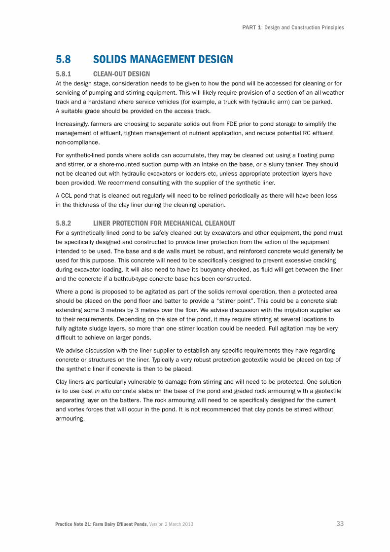
33Practice Note 21: Farm Dairy Effluent Ponds, Version 2 March 2013
PART 1: Design and Construction Principles
5.8 soLiDs ManageMent Design5.8.1 CLean-out DesignAt the design stage, consideration needs to be given to how the pond will be accessed for cleaning or for
servicing of pumping and stirring equipment. This will likely require provision of a section of an all-weather
track and a hardstand where service vehicles (for example, a truck with hydraulic arm) can be parked.
A suitable grade should be provided on the access track.
Increasingly, farmers are choosing to separate solids out from FDE prior to pond storage to simplify the
management of effluent, tighten management of nutrient application, and reduce potential RC effluent
non-compliance.
For synthetic-lined ponds where solids can accumulate, they may be cleaned out using a floating pump
and stirrer, or a shore-mounted suction pump with an intake on the base, or a slurry tanker. They should
not be cleaned out with hydraulic excavators or loaders etc, unless appropriate protection layers have
been provided. We recommend consulting with the supplier of the synthetic liner.
A CCL pond that is cleaned out regularly will need to be relined periodically as there will have been loss
in the thickness of the clay liner during the cleaning operation.
5.8.2 Liner ProteCtion for MeChaniCaL CLeanoutFor a synthetically lined pond to be safely cleaned out by excavators and other equipment, the pond must
be specifically designed and constructed to provide liner protection from the action of the equipment
intended to be used. The base and side walls must be robust, and reinforced concrete would generally be
used for this purpose. This concrete will need to be specifically designed to prevent excessive cracking
during excavator loading. It will also need to have its buoyancy checked, as fluid will get between the liner
and the concrete if a bathtub-type concrete base has been constructed.
Where a pond is proposed to be agitated as part of the solids removal operation, then a protected area
should be placed on the pond floor and batter to provide a “stirrer point”. This could be a concrete slab
extending some 3 metres by 3 metres over the floor. We advise discussion with the irrigation supplier as
to their requirements. Depending on the size of the pond, it may require stirring at several locations to
fully agitate sludge layers, so more than one stirrer location could be needed. Full agitation may be very
difficult to achieve on larger ponds.
We advise discussion with the liner supplier to establish any specific requirements they have regarding
concrete or structures on the liner. Typically a very robust protection geotextile would be placed on top of
the synthetic liner if concrete is then to be placed.
Clay liners are particularly vulnerable to damage from stirring and will need to be protected. One solution
is to use cast in situ concrete slabs on the base of the pond and graded rock armouring with a geotextile
separating layer on the batters. The rock armouring will need to be specifically designed for the current
and vortex forces that will occur in the pond. It is not recommended that clay ponds be stirred without
armouring.

34 Practice Note 21: Farm Dairy Effluent Ponds, Version 2 March 2013
PART 1: Design and Construction Principles
5.8.3 sLuDge BeDs, BunKers, anD Draining PaDsIf solids are to be stored on site then these will need to be held on a confined area designed and
constructed to provide at least the same permeability criteria as the pond liner, which is 1 × 10⁻⁹ m/s, or
as required in the Resource Consent. Lining options for sludge beds/bunkers and draining pads include:
▪ A concrete slab floor with a nib wall or bunker wall. Practically and serviceability wise, concrete gives a good long-term result
▪ A GCL under a confining layer of cohesive material
▪ A premium-grade synthetic liner in conjunction with a geotextile underliner. A textured HDPE liner with a cohesive cover layer is another option.
The design of these structures needs to be such that effective draining and drying can occur. Drainage
from the base needs to be either contained or directed back into the effluent containment system.
5.9 Liners 5.9.1 Liner oPtionsLiners can be formed from compacted clay; or specially manufactured geomembrane materials such as
polyethylene, polypropylene, synthetic rubber, geosynthetic clay; or concrete.
It is imperative that the type of liner selected is appropriate to the intended purpose and that due
diligence is observed during preparation, installation, and subsequent use. No matter what type of
lining material is used, defects from inappropriate installation or use are likely to result in consent
non-compliances, costs of remedial work, and wasted capital invested in a structure that fails to control
environmental liabilities.
Pond Lining options refer
In-situ clay Part 2
Compacted clay Part 2
Geomembranes (synthetic liners) Part 3
Concrete Part 1, Section 5.9.2
Table 5.3: Pond lining options
5.9.2 ConCrete LinersSprayed concrete using compressed air, also referred to as Shotcrete, can be placed as a wet or dry
concrete mix to form a liner.
To avoid slumping, this concrete mix is likely to be a special mix of chemical additives, silica sand, fly ash
or aggregate, and cement. Synthetic fibres may also be used as an alternative to the use of a wire mesh
or metal reinforcing bars. The addition of such fibres will provide improved compressive strength, flexural
capacity, and impermeability.
A geotextile or synthetic liner under the liner is required to minimise soil contamination and to dissipate
groundwater and sub-surface gases.

35Practice Note 21: Farm Dairy Effluent Ponds, Version 2 March 2013
PART 1: Design and Construction Principles
5.10 PonD PerforManCe ConsiDerations 5.10.1 Drainage ControL anD LeaK DeteCtion systeMsPiping failure (erosion along lines of weakness) in soils underlying ponds should not be an issue with
a properly constructed and maintained FDE pond where leakage is very low. If foundation soils are
dispersive, or otherwise prone to piping and formation of sub-soil cavities (tomos), specific underdrainage
provision may be prudent.
An FDE pond would not normally be designed with secondary lining and leak detection systems; however
RCs are increasingly encouraging these features in pond design. Foundation soils will generally be orders
of magnitude more permeable than the pond liner. Small leakages will dissipate to the soil. If underlying
soils are slowly permeable (for example, <1 × 10⁻⁶ m/s), then an underdrainage system (gravel layer or
strip drain) could be incorporated.
Whilst is it recommended that the highest water-table level for a site be below the base level of the pond,
this is not always achievable. In this situation, liner and pressure release design is particularly important.
Water drainage and water table management can be via trenches. Generally these are either permeable
material wrapped with a geotextile or perforated drainage pipe wrapped with a geotextile to avoid
finer particles entering. Drains should be placed approximately five metres apart, in addition to being
positioned around the foot of the base perimeter. For smaller ponds a ring drain placed at the foot of
the batter slope should be suffice. To further aid drainage, allow for 100 mm of drainage metal over the
drainage system.
The water drainage network should culminate in an inspection point; this allows the collected liquid to be
tested and liner leakage to be ruled out.
A Leak Detection System (LDS) installed at the time of pond construction will provide a very convenient
means of providing ongoing leakage detection. These systems consist of a water drainage network
(aggregate or piping with impermeable base layer) underneath any clay or synthetic liner, which drain
to an inspection well. Liquid in the well can be easily inspected, collected, and, if necessary, tested to
determine the source; groundwater will tend to be low in nutrients, solids, and bacteria, whereas FDE will
be high in all three.
The well itself should be 400 mm or greater in diameter, for example, formed from a length of culvert pipe
and able to be easily sampled from (using a suction pump or grab system). Further, the inspection well
should be weathertight, stock-proof, and sealed around the ground surface.
A pond drop test may provide a more conclusive measure of water-tightness but only if there is a major
leak. However, an effective LDS will provide a much earlier indication of leakage.
An alternative LDS technique that is relatively new to New Zealand is electric field testing. Water as a
conductive medium is applied to a membrane surface, and a tear or leak in the membrane creates a fault
that can be detected.

36 Practice Note 21: Farm Dairy Effluent Ponds, Version 2 March 2013
PART 1: Design and Construction Principles
5.10.2 gas DrainageDrainage of gas from beneath the liner is an important consideration where synthetic membrane
liners are used. If the pond has a large flat area and gas is unable to escape to the surface, then the
liner will float in large bubbles (also known as humpback whales or hippos). Gas could be the result
of decomposition of organic matter in the soil (for example, peat, residue from an old unlined pond,
unknown leaks), air trapped by a fluctuating water table, or decomposing effluent (from a previous pond).
Gas drainage could be provided by an aggregate layer beneath the liner (in which case, check for
compatibility between the liner membrane and the stone size, or by synthetic drainage products, with a
minimum fall of two per cent to allow for positive gas movement. Gas should then be appropriately vented
to the surface. Note some saturated gases will drain downhill and may need to be dealt with separately to
volatile gases.
The geometry of the pond base is important to ensure gas drainage – slope at one per cent upward from
the centre. A narrow base width of with shallow batters could be a better configuration than a wide base
with steeper batters if gas is anticipated.
Geotextile is often recommended for both clay and synthetic liners, sometimes above and below, but in
particular, underneath the liner. The purpose of a geotextile is to provide separation of fines or to protect
the liner from puncturing. Some geotextiles available provide both fines separation and gas drainage.
5.10.3 heaLth anD safety reQuireMents Steep lined slopes, whether slick clay or synthetic membrane, are a hazard for farm workers (and stock).
All ponds should include at least one ladder or alternative escape means in the event of a fall into a pond.
Larger ponds will require several such escape routes.
Similarly, all ponds should be fenced off with a netting fence to prevent stock (and children) from straying
and falling into the pond.
Key Points
▪ Pond storage volume: allow for maximum herd size, any silage pit and feedpad runoff, rainfall, yard wash-down, future-proofing.
▪ Prepare detailed construction documents: drawings, specification, schedule of quantities, cost estimate.
▪ Orientate pond to reduce potential adverse effects of flooding and wave action.
▪ Include drainage and gas venting systems in pond design.
▪ Where a pond requires stirring, ensure pump sufficient to adequately stir the volume. needed without liner damage, also factor in maintenance and safety requirements.
▪ Seek and consider advice from liner/containment specialists.

37Practice Note 21: Farm Dairy Effluent Ponds, Version 2 March 2013
PART 1: Design and Construction Principles
6.0 Construction6.1 introDuCtionEvery FDE pond is different and there will be variations in the design and construction of each. This
section sets out a number of items that should be considered by farm owners, contractors, suppliers,
as well as the Suitably Qualified Person (SQP) who will be signing off the work:
▪ Meeting consent and regulatory requirements
▪ Preparing a specification
▪ Monitoring the construction contractor
▪ Ensuring quality-assurance requirements are being met
▪ Meeting the principal’s needs.
6.2 Drawings anD sPeCifiCations For a contractor to construct a pond that achieves the design criteria, then detailed drawings and
specifications are required.
Drawings need to provide sufficient detail so that the contractor can clearly understand the designer’s
intentions and requirements.
A good starting point for a specification is NZS 4431:1989 (Earth Fill for Residential Development),
particularly sections 6–11. Both practitioners and contractors should make themselves familiar with
the requirements of that Standard.
6.3 the suPerVising engineer’s roLe Before a contractor’s offer is accepted, it is advised that the proposed construction programme be
confirmed as this provides some certainty to the principal around timing and completion for the works.
At the works’ commencement, the SQP should ensure that the contractor has a copy of the Resource
Consent issued by the RC which permits the pond to be constructed (if that is required), and that the
contractor and SQP are fully aware of any Resource Consent conditions. Furthermore, during construction
the SQP will need to monitor the construction activities and confirm that all specification requirements
are being complied with.
The level of construction management needs to be determined by the SQP prior to construction in con-
sultation with the principal, and will depend on the complexity of the project. The construction monitoring
services section on the IPENZ website provides guidance on this.
During excavation, the supervising engineer needs to be aware of any material substantially different from
that revealed in the pond site investigation and soil geotechnical analysis. If encountered, the differing
material will have to be assessed and pond design or construction adjusted accordingly. An adjustment
may require formal amendment or variation of the Building Consent under the BA (and possibly the
Resource Consent under the RMA too) prior to undertaking that building work as the adjustment is not
consented and the completed work may not be able to be certified.
The person signing off the construction review (the SQP) must satisfy themselves that sufficient
compaction to the fill material has been applied. This may be determined by a combination of laboratory
and field tests, or compaction trials, together with experience in the plant and materials being used.

38 Practice Note 21: Farm Dairy Effluent Ponds, Version 2 March 2013
PART 1: Design and Construction Principles
If the contract works are to be completed under NZS 3910 then the issuing of the Practical Completion
and Defects Liability Certificates will need to be assessed and completed.
6.4 effeCts of worKs on others The contractor will need to carefully consider the site conditions and timing of the contract with respect
to the potential for runoff, dust, and noise generation from the works.
The contractor should arrange and control the work so that the construction of the pond will not cause
contamination of waterways or a dust nuisance to any nearby properties. A water cart should be on site
to dampen down any area causing a dust nuisance.
Works may have to be arranged to minimise inconvenience to the farmer in their dairy farm operation
and work around cow movements and milking times.
6.5 unDergrounD serViCes Utility providers and the farm owner/manager will need to be approached as to the location, line, and
level of underground services before commencing operations in a particular area, and take steps
necessary to prevent damage to, or accidents arising from, interference with any pipes, cables, ducts,
and underground structures.
Permanent relocation of water troughs, water pipes, and irrigation infrastructure may be necessary
and relocation arrangements for these agreed with the farmer.
6.6 Drainage ControL Measures should be taken early in the work to maintain the natural water drainage facilities and avoid
the introduction of water into the earthworks. Adequate provision should also be made for the control of
water-borne soils/silts and the contractor may need to install temporary silt fences to protect waterways
from contamination.
In addition, temporary drainage works may be required during construction to control groundwater and
surface water and safeguard the integrity of the works. It is important that the earthworks be carried
out in such a manner that surfaces have a sufficient fall at all times to shed water and prevent localised
ponding.
Where an existing subsoil drainage or drainage path is encountered or will be intercepted, subsoil drains
need to be constructed to direct flows away from the constructed fills and embankments. These subsoil
drains need to have sufficient fall to prevent blockages and be self-cleaning.
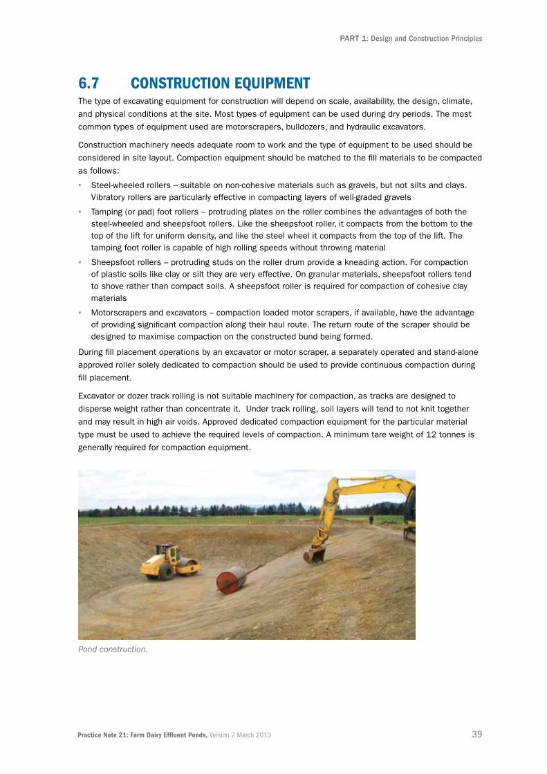
39Practice Note 21: Farm Dairy Effluent Ponds, Version 2 March 2013
PART 1: Design and Construction Principles
6.7 ConstruCtion eQuiPMent The type of excavating equipment for construction will depend on scale, availability, the design, climate,
and physical conditions at the site. Most types of equipment can be used during dry periods. The most
common types of equipment used are motorscrapers, bulldozers, and hydraulic excavators.
Construction machinery needs adequate room to work and the type of equipment to be used should be
considered in site layout. Compaction equipment should be matched to the fill materials to be compacted
as follows:
▪ Steel-wheeled rollers – suitable on non-cohesive materials such as gravels, but not silts and clays. Vibratory rollers are particularly effective in compacting layers of well-graded gravels
▪ Tamping (or pad) foot rollers – protruding plates on the roller combines the advantages of both the steel-wheeled and sheepsfoot rollers. Like the sheepsfoot roller, it compacts from the bottom to the top of the lift for uniform density, and like the steel wheel it compacts from the top of the lift. The tamping foot roller is capable of high rolling speeds without throwing material
▪ Sheepsfoot rollers – protruding studs on the roller drum provide a kneading action. For compaction of plastic soils like clay or silt they are very effective. On granular materials, sheepsfoot rollers tend to shove rather than compact soils. A sheepsfoot roller is required for compaction of cohesive clay materials
▪ Motorscrapers and excavators – compaction loaded motor scrapers, if available, have the advantage of providing significant compaction along their haul route. The return route of the scraper should be designed to maximise compaction on the constructed bund being formed.
During fill placement operations by an excavator or motor scraper, a separately operated and stand-alone
approved roller solely dedicated to compaction should be used to provide continuous compaction during
fill placement.
Excavator or dozer track rolling is not suitable machinery for compaction, as tracks are designed to
disperse weight rather than concentrate it. Under track rolling, soil layers will tend to not knit together
and may result in high air voids. Approved dedicated compaction equipment for the particular material
type must be used to achieve the required levels of compaction. A minimum tare weight of 12 tonnes is
generally required for compaction equipment.
Pond construction.

40 Practice Note 21: Farm Dairy Effluent Ponds, Version 2 March 2013
PART 1: Design and Construction Principles
6.8 CoMPaCtion 6.8.1 CoMPaCtion theoryGetting the target compaction at the right water content into the constructed embankment material is
the key to providing an embanked pond meeting acceptable stability and permeability requirements.
The relationship between moisture content and density for a given soil under a given level of compaction
can be represented by Figure 6.1 below. These graphs are not universal, they are unique to a particular
soil (or mix of soils) under a given compaction effort.
Compaction curves shift up and to the left as the compaction effort increases, for example, by an
increase in roller size or number of passes. The black curve in Figure 6.1 demonstrates a higher
maximum density being achieved than for the red curve. For the same material, the only difference
between the two curves is the amount of compactive effort being applied. Also note the effect of
moisture on achievable density. If the material is too wet, then the maximum density cannot be achieved.
For clay embankments it is better to compact slightly dry of OMC as increased compactive effort can
provide a higher density without water being trapped in pores. For sands and gravels it is better to
compact over the OMC as excess water can provide particle lubrication while being able to drain away
without pore pressure build up.
A Dry Density/Moisture Content (DD/MC) curve can be produced in a laboratory by wetting up samples
at different moisture contents and compacting at NZ standard compaction. These samples can also
be tested with a shear vane so as to provide a comparative means to check soil strength and moisture
content in the field.
The design process should confirm and specify the minimum construction requirements, such as the
number and depth of soil layers, the target percentage of maximum density, and the moisture content
required to achieve the necessary soil compaction.
2.000
1.950
1.900
1.850
1.800
1.750
1.700
1.650
1.600
6 8 10 12 14 16 18 20Moisture Content %
Dry
Den
sity
t/m
3
Compaction Curve
Density Curve 10% Air Voids5% Air Voids10% Air VoidsDensity Curve 2
Figure 6.1: Dry Density/Moisture Content Relationship

41Practice Note 21: Farm Dairy Effluent Ponds, Version 2 March 2013
PART 1: Design and Construction Principles
6.8.2 CoMPaCtion testing: eMBanKMentsSampling and laboratory testing of the proposed in situ fill material to determine the Maximum Dry
Density (MDD) and OMC is best done prior to commencing earthworks construction. From these test
results the supervising engineer may confirm target values. Table 6.1 provides details of standard tests
and rates of testing. These rates for embankment fill testing are the same irrespective of whether a
geomembrane or clay liner are to be installed. For clay liner testing refer Part 2, Table 2.
test stanDarD MiniMuM rate of testing
Compaction MDD and OMC
NZS 4402.4:1986 Test 4.1.1 One test, but more if material shows any variation
In situ density and voids content
NZS 4407:1991 Test 4.2.1, Direct Transmission Mode
One test per 50 m2 of surface area of compacted layer, but not less than 10 tests. Minimum of two sets of tests to be taken; at 0% (trial) and 100% of fill placement completion
Acceptance criteria: >95% MDD and ± 3% of OWC < 6% voids
Table 6.1: Embankment Testing
Alternatively, if MDD results are not available or the fill material is different from the test results available,
the supervising engineer may predetermine the compaction requirement by compaction trial.
The contractor should obtain from an IANZ-accredited testing laboratory, or other agency approved by
the supervising engineer, sufficient test results and other measurements to show that the construction
is in accordance with the drawings and specification. The contractor must supply copies of test results,
certificates etc, to the supervising engineer to confirm that materials or works comply before progressing
to the next phase of construction.
If the supervising engineer tests any part of the works and finds that it is not in compliance with the
specified requirements, the contractor should be made aware that they are liable for the cost of retesting,
including any costs incurred by the supervising engineer and principal.
6.8.3 CoMPaCtion triaLA trial strip using the proposed each cut-to-fill or borrow-to-fill material is recommended. This is to
determine:
▪ The effectiveness of the contractor’s equipment with the proposed fill materials to achieve the specified compaction density by using a nuclear density meter (NDM) in comparison to the DD/MC test report provided by the supervising engineer
▪ The number of roller passes necessary to achieve the specified density.
For clay materials, Scala Penetrometer and shear vane readings on the completed trial embankment
may provide a useful reference tool for subsequent compaction control, but should not be used for fill
compaction acceptance purposes.
The contractors specification should indicate that the contractor will arrange, and pay for, all labour, plant,
and materials required to construct and test the trial embankment. If this service is required it should be
clearly stated in the contract documents.

42 Practice Note 21: Farm Dairy Effluent Ponds, Version 2 March 2013
PART 1: Design and Construction Principles
6.8.4 ConstruCtion gooD PraCtiCe It is desirable to keep topsoil separated from subsoil materials during excavation. Topsoil material
needs to be placed in a location where it can be accessed after excavation has been completed.
Material should be placed and compacted in progressive, uniform horizontal layers not exceeding
150mm compacted thickness. Careful attention is required to ensure foreign material not intended for
compacted fill layers is not mixed with fill material to prevent modifying the properties of the intended
fill material.
Pond banks and crests are best formed by over-constructing and trimming back later to the required level
and slopes. Final trimming and static rolling is required to produce an even and tight surface.
The finished top bank width should be more than the roller width. For safety, the bank should be made
over dimension so that the roller does not need to work right to the outer edges of the bank since these
will be trimmed back later. The crest (embankment top) should also be slightly sloped back throughout
construction to prevent rainfall flowing back into the pond.
Compaction should not continue if the material shows signs of heaving or weaving excessively. In this
situation, the material should either be left to dry naturally or, where work progress would be affected by
a delay, the material should be dried to a moisture content at which heaving and weaving does not occur.
Fill surfaces and materials must be protected from becoming wetter than OMC. If materials become
wet, continuing with compaction becomes counterproductive and the required soil densities will not be
achieved. Valuable time will be lost in waiting for excessive built-up pore pressures (as evidenced by
surface heaving and rutting) to dissipate. The moisture content to achieve optimum compaction needs
to be continually monitored during construction.
It is good practice to seal off and slope surfaces away from the works at the end of the day or at the
onset of rain. Wet material can be dried either by mixing in drier material or spreading out the wet
material in a loose state on a warm or windy day to allow drying. Careful mixing in of small quantities
of bentonite can also be beneficial with some materials.
After the bulk earthworks have been completed, topsoil should be placed on the back slope surface
and sown out in grass to provide erosion control. Any shrubs or trees (including their roots) need to be
cleared well back from the embankment.
6.9 exPoseD Batters The exposed batters and crests of embankments should be topsoiled and revegetated as soon as
possible after construction, then grassed, hydroseeded, or suitably protected to prevent erosion from
rainfall, wind, or frost damage.
The back slope batter may be flattened further than the specified slope angle by the placement of excess
topsoil and other surplus fill material, but only if it is well compacted, surface-trimmed, and levelled.

43Practice Note 21: Farm Dairy Effluent Ponds, Version 2 March 2013
PART 1: Design and Construction Principles
6.10 fenCes anD gates The construction area should remain stock-proof at all times and the contractor should note that some
temporary fencing may be necessary to achieve this. All temporary fencing needs to be removed by the
contractor prior to works completion.
Fences and gates, as an access safety measure, will need to be installed in the locations as shown on
the construction drawings either by the contractor or the principal by agreement.
At project completion, any exposed old post holes require filling, the site should be left in a smooth, tidy
surface condition, and redundant fencing-related materials should be removed from the site.
6.11 PraCtiCaL CoMPLetion anD DefeCts LiaBiLity CertifiCates If NZS 3910 (or NZS 3915) is being used on the contract, and it is recommended that it is, then
Practical Completion and Defects Liability Certificates will need to be prepared by the supervising
engineer. The process for its issuing is as described in the NZS 3910 (General Conditions of Contract).
A link to Standards New Zealand Website is contained in the References section under Pond Design
and Construction.
The SQP should assess that all the following items (if specified) have been attended to:
▪ Topsoiling, grassing, and tidy smoothing up of the embankment and surrounds
▪ Completion of all work specified or scheduled in the contract documents
▪ Meeting all consent requirements
▪ That the principal is satisfied with the completed construction.
The defects liability certificate is due for the contract works (or any separable portion) when minor
omissions or defects have been repaired and the period of defects liability has expired. The period is
typically six months, but could be longer depending on local conditions.
Key Points
▪ Allow for local weather conditions.
▪ Match appropriate compaction equipment with fill material type.
▪ Monitor compaction, confirm with laboratory testing.
▪ Pay special attention to pipe penetration areas through embankments and liners.
▪ Issue practical completion and Defects Liability Certificates on satisfactory completion of all specified work.

44 Practice Note 21: Farm Dairy Effluent Ponds, Version 2 March 2013
PART 1: Design and Construction Principles
7.0 Certification7.1 introDuCtionMany pond owners may be satisfied with what they can visually see, supported by the judgement and
trust of the construction contractor involved. However, some regulatory authorities specify certification of
the work. This certification will generally be beyond the expertise of the owner and/or some contractors.
Institutions with a financial interest in a farm, including banks and insurers, may also require formal
certification to ensure that exposure to physical, financial, and legal risks has been appropriately
managed and minimised. This can include certification by an engineer where appropriate, and certificates
of compliance from councils to verify that regulatory requirements under the RMA have been met.
Certification under the BA has other certification requirements and approaches.
Where RCs require formal sign-off for the design and construction for ponds for which the BA does not
apply, then verification by a SQP is recommended. Defining who constitutes an SQP is necessary and this
Practice Note proposes the following definition:
“A person with the necessary competence, relevant qualifications, knowledge, skills,
experience, and understanding of soils, engineering materials and structures to design and
supervise the construction of effluent containment systems such that they are fit for purpose,
structurally sound, and meet all regulatory requirements. They shall be either a CPEng or
an Engineering Technology Practitioner (ETPract), or Regional and District Councils may
wish to individually approve other local practitioners as an SQP due to their long-standing
demonstration of these attributes.”
For pond owners where verification that structures including some ponds, tanks, and dams meet the BA
requirements, certification by a CPEng is the recognised process to verify that all regulatory, design, and
construction standards have been met.
A summary of design and construction certification requirements is set out in Figure 7.1.
This Practice Note focuses on the construction of new ponds and while it may provide guidance of
expected standards of existing ponds, it is not intended to be a retrospective design guide. The same
rationale applies to certification, with the recommendations for certification below applying to the
construction of new ponds.

45Practice Note 21: Farm Dairy Effluent Ponds, Version 2 March 2013
PART 1: Design and Construction Principles
7.2 CertifiCation unDer the rMa By regionaL CounCiLsThe acceptance of the design and construction of ponds in some regions is covered by the RC and left
to a FDE practitioner to use industry accepted codes, such as NZS 4431 (Code of Practice for Earth
Fill for Residential Development) and section 2 of NZS 4404 (Land Development and Subdivision
Engineering), or specific design principles where applicable. Due to the variability associated with the
materials used for construction, some element of specific design is required for each application. NZS
4431, while specific to residential development, does give prudent guidance on the construction of
earthfills for bulk earthworks. It should not be used for clay liner placement as that is specific design
based on the clay material used.
While suppliers and installers of synthetic and concrete pond liners will normally be able to provide
their own certification of permeability, earthen pond liners provide a significant challenge. Councils do
not specify the method or means by which such permeability is to be measured; they typically require
certification by an engineer that the specified permeability rate is not exceeded.
This Practice Note recommends that that an SQP completes a Producer Statement (Design) and Producer
Statement (Pond Construction Review). Examples of suitable forms for Producer Statements for SQPs are
contained in Appendix B.
To provide continuity between the design and construction phases it is preferable, but not essential, that
the same SQP be involved throughout the project. However, only one SQP can sign off on each or both
phases.
7.3 CertifiCation unDer the BuiLDing aCt As with the RMA, different aspects of the BA are administered by regional and district councils
respectively.
7.3.1 CertifiCation By regionaL CounCiLsThe focus of the regulation of ponds by RCs under the BA is the safety and integrity of dams. Specific
regulations and requirements are discussed in section 3.
If a pond is not a “large dam”(as categorised by Table 3.5), then there is no requirement for a Building
Consent to be granted by the RC. However, with a structure that is “not a dam” or a “dam”, there is still
a requirement for it to be constructed to meet the performance requirements of the under section 17 of
the Building Code.
Compliance with the Building Code for a pond or dam is left to a dam owner’s judgement in that there is
no requirement for any BCA approval or confirmation that those requirements have been met. However,
persons or institutions with a financial interest in a farm, including banks and insurers and prospective
farm purchasers doing due diligence, may well have an interest in seeing formal confirmation that a pond
has in fact met Building Code requirements. A physical failure of a dam has the potential to bring about
an investigation by the RC, and a dam owner who is unable to provide documentary evidence of Building
Code compliance will potentially be in difficulty.

46 Practice Note 21: Farm Dairy Effluent Ponds, Version 2 March 2013
PART 1: Design and Construction Principles
7.3.2 ProDuCer stateMents for BuiLDing Consent authorities The Producer Statement process is intended to provide BCAs with reasonable grounds for the issue of a
Building Consent or a Code Compliance Certificate, without having to duplicate design or construction
checking undertaken by others. The four categories of Producer Statement are:
▪ PS1 (Design)
▪ PS2 (Design Review)
▪ PS3 (Construction)
▪ PS4 (Construction Review).
For the certification of the design and construction of tanks, ponds, or dams under the BA, PS1 and
PS4 should be produced, whether required for a Building Consent or simply to establish Building Code
compliance where consent was not required. These statements will be appropriate whether the pond
involves a dam or not, and whether the BCA is the RC or the DC.
These statements should also be appropriate to meet any engineering requirements of DCs under the
RMA, and should similarly meet any earthworks certification requirements of councils under the RMA.
Generally only a CPEng has the legal authority to sign-off on such Producer Statements (that is, PS1
to PS4). The Producer Statements forms in Appendix B are intended for SQPs to complete are not for
this purpose.
7.4 CertifiCation By ConstruCtion ContraCtor If an FDE pond is constructed by contractors, and either NZS 3910 or NZS 3915 is used as a form of
contract, then the SQP should seek a Producer Statement in the form of Schedule 6 from the contractor.
As-built plans should also be requested.
If an FDE pond and any ancillary works are to be constructed under another contractual arrangement, for
example, the principal is undertaking his own management of the contractor, then a Producer Statement
should still be provided by the contractor. A suitable Producer Statement form for construction signoff
for contractors to use is in Appendix B. The significance of the Producer Statement should be discussed
between the SQP, contractor and the principal prior to work commencement.
Should a liner be installed separately to the pond contractor’s scope of work, then installers of such a
liner will need to provide the necessary certification in the form of a Producer Statement to the SQP on
behalf of the principal.
Where components of a structure are supplied by a manufacturer and are to be incorporated into the
contractor’s works, for example, precast concrete panels, then the BCA may require Producer Statements
for these as part of the Building Consent sign-off before the issuing a Code of Compliance Certificate.

47Practice Note 21: Farm Dairy Effluent Ponds, Version 2 March 2013
PART 1: Design and Construction Principles
7.5 CertifiCation for PonD Design anD ConstruCtion reView IPENZ has an industry-recognised and respected accreditation system providing competence-based
registers for engineers. Two of these registers are appropriate to apply to FDE pond design and
construction; these being CPEng and ETPract. These two quality marks can provide both Regional and
District councils with the confidence needed to accept the design and construction of FDE ponds, but only
where ponds are exempt from Building Consents.
Both CPEng and ETPract persons are bound by ethical guidelines to only certify work that they are
competent in, that is, within their practice area, providing further reassurance to councils. For links to the
IPENZ Code of Ethics and ethical obligations refer to the References section.
As a further note, DairyNZ has developed an accreditation process for companies who are designers
of FDE systems. This programme is primarily aimed at FDE land application systems, but not at pond
design and construction, and allows the participation of rural professionals and contractors who do not
necessarily have professional engineering qualifications.
Key Points
▪ An SQP needs to be engaged prior to design and construction.
▪ Practitioners need to be ethical at all times.
▪ Check that regional and district council requirements are being met.
▪ The SQP and contractor(s) need to provide Producer Statements for their work.

48 Practice Note 21: Farm Dairy Effluent Ponds, Version 2 March 2013
PART 1: Design and Construction Principles
Figure 7.1: Summary of Design and Construction Certification Requirements

49Practice Note 21: Farm Dairy Effluent Ponds, Version 2 March 2013
PART 1: Design and Construction Principles
8.0 operation and Maintenance8.1 introDuCtion This section provides a brief summary of what needs to be considered for the effective operation and
maintenance of FDE ponds.
8.2 as-BuiLt PLans As-built plans of the FDE pond should be supplied by the pond construction contractor to the client upon
completion. These provide a valuable record and assists with operations, inspections, and monitoring.
As-built plans should include:
▪ Key levels of base and embankment crests in relation to datum, for example, a level at the dairy shed, so any future settlement or impact of pond cleaning can be assessed
▪ Location, depth, and diameter of all pipes entering and leaving the pond
▪ Location of power cables
▪ Details of any under-drainage and gas drain provision
▪ Location of subsoil drains and leak detection features.
8.3 oPeration ManuaL An FDE operation manual should be prepared by the SQP and the equipment and service suppliers in
consultation with the principal. All dairy farm staff should be familiar with the manual. One of the most
important aspects to include is where and how sludge is to be removed. This includes:
▪ Where the pond may be accessed for desludging, including providing a plan which can be copied for contractors
▪ How and what equipment may (and may not) be used
▪ The location where the removed sludge is to be deposited
▪ The appropriate method and depth of sludge spreading
▪ Pond area groundwater monitoring.
The operation manual should also include information on:
▪ Frequency for the drop test (yearly generally, but more frequently if stirrers and regular mechanical desludging takes place)
▪ Contact details for repair of synthetic liners
▪ Maintenance requirements for pumps, valves, and mixers
▪ Vegetation control
▪ Meeting and monitoring resource consent conditions.
8.4 insPeCtionsThe following inspections should be carried out by farm management staff, and results recorded so they
can be supplied to consent compliance staff if necessary:
▪ Monthly inspection for general condition (photographs will help to track changes over time)
▪ After any desludging operation, looking for any obvious signs of damage
▪ After any unusually heavy rain (for example, >50 mm in 24 hours).

50 Practice Note 21: Farm Dairy Effluent Ponds, Version 2 March 2013
PART 1: Design and Construction Principles
As a minimum, the following items should be checked during an inspection:
▪ Pond level – is there sufficient freeboard? Consider if it should it be as empty as it is or if there could be groundwater ingress raising the water level
▪ Maintenance of vehicle access and crest of the pond– to allow easy desludging equipment access, including in an emergency
▪ Synthetic liners – no tugging or tearing is present from anchor trench, no visible or obvious damage to liner
▪ Clay liners – no excessive erosion, drying, cracking, or damage to liner
▪ Pipework – check for leaks or damage to pipes
▪ Bunds – no obvious bund failures or damage
▪ Modifications – have there been any recent modifications to the pond that have not been recorded?
The New Zealand Society on Large Dams (NZSOLD) publication Guidelines on Inspecting Small Dams
gives a general overview of what to look for, and why, when inspecting a small dam.
8.5 PonD Monitoring Changes in colour, appearance and odour of a pond contents, as well as significant changes in level,
can be indicators of issues with the system.
Wet swampy patches or particularly lush areas of grass can be indicators of leaks. These should be
investigated early to avoid unnecessary damage to the liner.
Loss of freeboard requires urgent attention by farm management staff. While high-level alarms that
can be monitored remotely could be installed to monitor this, a simple level indicator may also be
appropriate.
The water level in storage ponds should be monitored regularly, along with groundwater heights and
sludge depths. Monitoring of effluent levels allows any seepage losses to be readily detected and
corrected. To monitor groundwater, a shallow (up to three-metre) slotted PVC pipe in which depth is
measured is satisfactory. Monitor these levels monthly during wet periods when water tables are
likely to rise.
8.6 LeaKage DeteCtion anD resPonseIn the event that surveillance, either by drop test, obvious seepage, or monitoring beneath the liner, gives
concerns that the pond may be leaking, then remedial action will be necessary.
The first action should be to pump the pond’s water level right down, and for a synthetic-lined pond, clean
out the base, then visually inspect the lining. A clay liner may show obvious damage from machinery or
erosion. Repair of damage to clay liners could involve placing more clay and compacting in with a plate
compactor (if localised), placing GCL sheet, or if more extensive, ripping and re-compacting the liner.
Major repair of clay liners should involve an experienced practitioner.
Damage to a synthetic liner can be difficult to pick up. While damage such as a tear or large penetration
by machinery might be easy to see, some damage such as pinholes or defective welds will be less
obvious. Inspection by the liner installer may be helpful. Alternatively, if the groundwater outside the liner
is high, then defects will show as water weeping back into the pond. Repairs to synthetic liners should
only be carried out by an experienced liner installer.

51Practice Note 21: Farm Dairy Effluent Ponds, Version 2 March 2013
PART 1: Design and Construction Principles
8.7 DroP test A drop test will be unsuitable to verify that a liner has achieved the recommended maximum leakage
rate due to wave movement, evaporation and the limitations of measuring very small changes in level
accurately. However, a carefully run drop test will indicate if there is gross leakage, being a large single-
point leakage, or a number of smaller leaks in a liner. While a drop test may be carried out at any liquid
level within the pond, the worst case situation will be when the pond is up to freeboard level. This will be
the level where leaks will be more easily detected if there are any.
The procedure for a drop test is as follows:
▪ Shut off any liquid inflows, including rainwater diversion (if in place)
▪ Choose a period of likely fine weather and preferably when cows are dry
▪ Securely fix an accurate water-level recording device at a suitable calm location
▪ To measure evaporation, fill a container of approximately 500 mm diameter by at least 300 mm deep with liquid from the pond to within 100 mm of top, weigh or measure level and float in pond
▪ Record change in level, ideally over 24 hours.
After allowing for evaporative loss, the water drop should be negligible (that is, less than one millimetre)
for a pond with no discernable leakage.
The following information should be collected for a drop test:
▪ Name of tester and date
▪ Dimensions of pond – length by width by depth
▪ Depth and type of clay
▪ Depth to groundwater
▪ Test methodology
▪ Local weather conditions, including rainfall measurement, wind, temperature, and barometric pressure
▪ Calibration of the water-level recorder
▪ Graph showing level fluctuations with corrections over the test period
▪ Testing should run for at least 48 hours, although a longer period may provide a more definitive result.
8.8 systeM oPeration 8.8.1 treatMent LeVeLs To ensure that the FDE pond system is operating effectively and treatment levels are maintained,
the following measures must be undertaken:
▪ Carry out desludging at regular intervals
▪ Correct operation of upstream solids removal to maintain settling
▪ Diligent use of rainwater diverters to avoid hydraulic shocks
▪ Maintenance of aeration and/or mixing systems.

52 Practice Note 21: Farm Dairy Effluent Ponds, Version 2 March 2013
PART 1: Design and Construction Principles
8.8.2 DesLuDgingMonitoring sludge depths is critical to ensuring sufficient room in the pond for heavy rain. As sludge
accumulates, the capacity for effluent diminishes, so ponds must be regularly desludged.
The desludging of an FDE pond will be carried out by pumping the contents (including stirring) or digging
out the sludge. Care should be taken to ensure that the desludging process does not damage the
embankment or liner. It is recommended that a concrete base be constructed where ponds are designed
to be desludged with machinery. The installation of a concrete base is also recommended beneath the
pump and/or stirrer to avoid damage to liner.
Sand traps must be cleaned regularly. A programme of sand and grit removal at the front end of the
effluent treatment system avoids carryover of these abrasive solids, which have very detrimental effects
on pumps, pipes, and valves, and adds to the solids on the bottom of the ponds.
8.8.3 oDours If an FDE pond becomes anaerobic it may give rise to odour. In order to minimise the incidence and
effect of odour, FDE pond design should take account of location and operational measures.
In a traditional FDE two-pond system there is usually little incidence of odour. This is because the pond
crusts over and the floating solids ensure the slow release of gas. Generally, odour only occurs in short
duration during desludging.
With a clear water holding pond, solids which could crust will have been removed, but soluble organics
and ammoniacal nitrogen remain and the deeper waters will rapidly go anaerobic. Gradual mixing of
the effluent within the pond will help aerate the liquid and remove and/or convert the ammonia from
the pond. This may lead to a brief instance of odour. At these times consideration should be given to
prevailing winds and potentially affected parties in the proximity of the pond.
Regular desludging, varying the level of effluent and turnover of liquid within the pond will also help
reduce the incidence of odour. Transfer sumps should be operated with a minimal range so that effluent
is mixed and pumped daily.
8.9 existing fDe PonDs If an existing FDE pond is to be used as part of a new or upgraded system, it will need to be
demonstrated that it meets the leakage criteria. The FDE pond will also be required to meet the relevant
regulatory standards.
If the FDE pond has not been certified by an SQP, the engineer will need to inspect and test the pond and,
if appropriate, provide certification.
Key Points
▪ Provide detailed plans and specifications.
▪ Develop an operation manual that includes a desludging plan.
▪ Encourage regular monitoring of pond for leakage.
▪ Stirring the pond can avoid odour.
▪ Keep pond volumes low during summer to allow filling during wet periods when soil saturated and unable to irrigate onto land.
53Practice Note 21: Farm Dairy Effluent Ponds, Version 2 March 2013
PART 1: Design and Construction Principles
9.0 forms of Contract 9.1 sCoPe of worK anD PraCtitioner engageMent The rural sector is very much relationship-based and these people expect others to keep their word.
However, this characteristic can be a problem because with a relatively new area like certified pond
construction, which farmers are generally unfamiliar with, there is a real risk of disappointing outcomes
for them.
It is important that the client clearly understands the scope of work proposed, the programme, and
the fee basis for the services being offered by the FDE-related services provider, whether they be an
engineering consultant, a pond contractor, or a liner installation company. A formal written contract
between the parties is a must. For FDE ponds, the most appropriate form of client and consultant
engagement contract is the IPENZ Short Form Agreement for Consultant Engagement and is contained
in Appendix A. Product suppliers will have their own forms for this purpose.
The scope of services to be provided by the practitioner should be clearly documented and agreed to by
the client so that there is full understanding by both parties from the outset. If working through a farm
management agent, then the engagement, design decisions, project management, and responsibility will
need to be clearly defined.
For the services provided by a practitioner, the following elements should be included in the scope of
services, unless excluded by agreement:
▪ Evaluation of the existing system if applicable
▪ Identification of improvement options/advise and best-practice systems
▪ Survey and geotechnical investigations
▪ Design
▪ Tendering and tender evaluation/recommendation
▪ Construction supervision
▪ SQP certification and reporting
▪ An operation and maintenance manual.
Research indicates that substantial savings can be made to the total project cost through good definition
of the project at the initial stage. If the issues are properly considered and agreed at the start of the
project, there is a greater likelihood that relationships will develop positively, greater assurance that the
client’s expectations can be satisfied throughout the project, and a successful conclusion for all parties.
9.2 ethiCs Clients typically rely on relative strangers for significant services in circumstances under which they
cannot assess the expertise or diligence of the service. This amounts to a significant risk for the client
and this is why IPENZ Members are required to avoid conflicts of interest and display expertise and
trustworthiness. Ethical practice is not an optional extra. IPENZ Practice Note 08 (refer to section 10)
further describes these obligations.
54 Practice Note 21: Farm Dairy Effluent Ponds, Version 2 March 2013
PART 1: Design and Construction Principles
9.3 ContraCtor seLeCtion Where there are aspects of the work which will be undertaken by others, such as supply and installation
of pumps to the FDE pond, it needs to be clearly defined who the parties are directly working for, that is,
either the practitioner or the client. In many cases, problems arise at the interface between the services
that the SQP and supplier are providing on the ground.
Similarly there needs to be an initial discussion and subsequent agreement around how the physical
works/contractor(s) are going to be selected and managed. Where specialist contractors are to be
engaged, for example, a synthetic lining contractor or a pump installer, who is going to project manage
them – the practitioner, the main contractor, or the client?
Some farmers may wish to project manage the construction work themselves. In this case the
practitioner will provide the design inputs and/or the final sign-off. The engineer should be careful with
such arrangements as they still need to be able to carry out periodic inspections and be able to influence
the quality of the construction as it proceeds.
The level of construction monitoring for the pond works should be determined early in the design
discussions and may be determined by the engineer’s confidence in the proposed contractors. The
IPENZ guide to construction monitoring services can be found in the References section.
Physical works contractor selection can take many forms and it is wise to discuss this with the
client first.
If the client has a preferred contractor and does not wish to approach any other contractor, it is still
important to prepare and supply the contractor with the following, as a minimum:
▪ Construction drawings
▪ Schedule of quantities
▪ Written agreement (NZS 3910, NZS 3915 or supplier/buyer agreement).
If a client wishes to have the physical works competitively tendered, then either invited tenders or
open tenders could be appropriate. A full contract document under either NZS 3910 or NZS 3915 is
recommended.
Tender evaluation may be solely based on price; however, in some cases where a particularly difficult
pond is to be constructed, track record and methodology evaluations may be appropriate. It would be
important to get the client’s expressed agreement for this, to ensure they understand the value this
approach would bring.

55Practice Note 21: Farm Dairy Effluent Ponds, Version 2 March 2013
PART 1: Design and Construction Principles
9.4 ContraCtor engageMent The principal, the contractor doing the physical works, and the engineer need to have their roles and
res-ponsibilities clearly defined before construction work commences. It is suggested that the traditional
rural way of accepting a contractor verbal offer by way of a handshake with no written agreement in place,
is not good practice. Given the cost of larger FDE ponds, and the risks involved with poor construction, it
is not recommended that contractors be engaged in such a way.
NZS 3910 (Standard Conditions of Contract for Building and Civil Engineering Construction) is the
benchmark for construction contracts that have the engineer to the contract defined. It clearly defines
the contractual relationship between a principal, the contractor, and the engineer and defines their rights,
obligations and communications. Furthermore it sets out procedures to for issues such as payments,
insurance, defects liability, and dispute resolution.
NZS 3910 is written using terms that are well understood and has been tested before the courts.
The Standard was developed by industry peers that included representation from central and local
government, professional and consulting engineers, contractors, and many others to produce a document
that is acknowledged as one of the fairest forms of contract in use.
Construction industry leaders promote the use of NZS 3910 in its standard form as an equitable form
of contract that is well-tested and fair, and provides certainty to all parties. Given the variability in some
effluent pond projects, NZS 3910 also provides an excellent framework to value variations in a way that
is fair and reasonable to both the principal and the contractor.
However, NZS 3910 can be quite complex for some clients used to a verbal contract; and for those not
willing, or if the scope of works are relatively small, then NZS 3915 can be used as this still provides the
relevant contractual engagements, legal status, and responsibilities of the relevant parties.
In both documents there are certification records required from the contractor on completion of works in
the form of a Producer Statement, which can be found in Schedule 6 of NZS 3910.
A defects liability period should also be utilised to provide a mechanism for the repair of defects not
obvious at the completion of physical works. A period of 26 weeks is usually adequate for FDE ponds.
The requirement for the contractor to provide insurance is also important, and provides reassurance to
both the client and the contractor if anything unexpected occurs. It is expected that the contractor have
the following insurances in place:
▪ Contract works (for larger projects)
▪ Public liability
▪ Plant and machinery
▪ Motor vehicle third party liability.
The inclusion of liquidated damages is worthwhile and may be appropriate for time or economically
sensitive contracts, as is a construction programme and completion date. An allowance for inclement
weather is usually provided.

56 Practice Note 21: Farm Dairy Effluent Ponds, Version 2 March 2013
PART 1: Design and Construction Principles
9.5 nzs 4431 (CoDe of PraCtiCe for earth fiLL for resiDentiaL DeVeLoPMent) NZS 4431 is a guiding document written to provide a proven methodology for the placement and
certification of fill, specifically for residential development. It can be used as a simple guide by all parties
involved to ensure any fill placed is done so appropriately.
Key Points
▪ Clearly define the scope of work offered.
▪ Signed formal agreement between practitioner/principal.
▪ Engage contractor under a formal contract, for example, NZS 3910.

Clay Liners for Ponds


59Practice Note 21: Farm Dairy Effluent Ponds, Version 2 March 2013
PART 2: Clay Liners for Ponds
1.0 introduction1.1 introductionClay liners for Farm Dairy Effluent (FDE) ponds can sometimes be an effective and economical method
for dairy effluent storage. Clay can be highly variable and so it is essential that thorough testing is under-
taken prior to and throughout construction of a clay liner. The costs of locating suitable clay sources and
subsequent construction will also need to be considered relative to other pond lining options available
such as geomembranes.
It is expected that in the future, older clay-lined effluent ponds on New Zealand dairy farms will come
under increased scrutiny by Regional Councils as they tighten their FDE storage containment rules.
Presently, compliance with containment rules is complicated by some industry confusion concerning the
various terms used in relation to storage ponds. Some Regional Council’s rules cite seepage or leakage
rates, while others use permeability or hydraulic conductivity rates with numbers such as 1 × 10⁻⁹ m/s
or 1 × 10⁻⁸ m/s, while yet others are nonspecific.
Part 2 sets out guidelines for good practice clay liner investigation, design and construction and should
be read in conjunction with the whole of IPENZ Practice Note 21: Farm Dairy Effluent Ponds.
KEY POINTSClay lining of FDE ponds can be successfully completed if the following key points are met:
▪ Investigations and full laboratory testing of the proposed clay source is undertaken
▪ The clay liner meets all laboratory test criteria, especially particle size and permeability requirements
▪ The minimum total thickness of clay liner to meet Regional Council’s seepage (leakage) or hydraulic conductivity (permeability) requirements needs to be specifically calculated for each site, but should not be less than 450 mm thick
▪ The clay is constructed with a minimum of three evenly compacted layers
▪ Cover or armouring material of sufficient thickness is spread over the clay lining to protect it from scouring, drying out and cracking
▪ A Quality Control testing programme is undertaken during liner construction to confirm compaction acceptance
▪ Design and construction personnel required to check and approve the work are actively involved in the project.

60 Practice Note 21: Farm Dairy Effluent Ponds, Version 2 March 2013
PART 2: Clay Liners for Ponds
2.0 design Calculations2.1 hydraulic ConductivityHydraulic conductivity is a measure of a soil’s ability to transmit water when subject to a hydraulic
gradient. The figure below describes the usual relationship between soil types and their inferred hydraulic
conductivity, and drainage capability.
Hydraulic Conductivity (m/s)
1.E-10 |
1.E-09 |
1.E-08 |
1.E-07 |
1.E-06 |
1.E-05 |
1.E-04 |
1.E-03 |
1.E-02 |
1.E-01 |
Low pervious semi pervious Pervious
Compacted Earth
Most soils drainage Materials
Compact Clay
Stratified Clay
Clay Loams
Silt Loams, Loess
Sandy Loams
Sand & Gravel Mixture
Clean Sands Gravel
Low pervious
Notes: This is a general guide only and should not be relied upon. Hydraulic conductivity in soils can vary due to changes in seepage fluid viscosity and soil water content.
Figure 2.1: Hydraulic Conductivity of Soils (Table adapted from FAO Training Series – Chapter 9: Soil Permeability)
2.2 seepage CalculationThe term “hydraulic conductivity” is often used interchangeably with “permeability” when water is the
seepage fluid. Regional Council rules usually quote maximum permeability values, as acceptance
normally relies on undertaking permeability tests on a clay-liner sample using water as the seepage
fluid in the laboratory.
The terms “seepage” and “leakage” rates are also used interchangeably and are a measure of the
flux. Flux is the rate of flow per unit area. No liner systems, including geomembranes, are completely
impermeable and all will have some seepage, albeit very low. Where the seepage rate reaches a
predetermined unacceptable value, then, for descriptive purposes, it might be renamed the leakage rate.
Seepage rate has a direct relationship with the hydraulic conductivity of a soil but also includes the head
of pressure, that is depth of the pond, and thickness of the clay liner. It is expressed as:
v = k ×∆h
∆l
v = seepage (or leakage) rate (m∕s)
Note: (v) is also referred to as the flux which is the rate of flow per unit area
k = hydraulic conductivity (also known as permeability) (m∕s)
∆h = vertical height from pond surface to base of liner (m)
∆l= liner thickness (m)

61Practice Note 21: Farm Dairy Effluent Ponds, Version 2 March 2013
PART 2: Clay Liners for Ponds
Furthermore:
q = k ×∆h
× A = v × A∆l
q = flow rate (m∕s or (litres∕day)
A = area (m2)
Example:
What is the seepage rate (v) from a pond that has:
Clay permeability (k) = 1 × 10⁻⁹ m∕s, Pond depth = 3.0m, Liner thickness (∆l) = 450mm
Seepage rate (v) =Hydraulic conductivity (k) × (pond depth + liner thickness ∆l)
liner thickness ∆l
= 1 × 10⁻⁹ m∕s × (3.0 + 0.45 m) / 0.45 m
= 7.6 × 10⁻⁹ m∕s
or = 7.6 × 10-9 × (1,000 × 60 × 60 × 24) mm∕day
= 0.7 mm∕day
2.3 flow and seepage with Varying hydraulic ConductivityThe relationship between seepage rate and typical hydraulic conductivity rates, assuming a constant clay
layer thickness, is plotted in Figure 2.2. For illustrative purposes only, it is based on a water filled pond
of theoretical surface area 1,000 m2 (for example 40 m × 25 m) × 3 m deep with impermeable vertical
walls. It also assumes that the material under and supporting the clay liner is free draining and does not
affect the hydraulic conductivity of the liner.
Figure 2.2: Flow (q) and Seepage (v) Rate with Varying Hydraulic Conductivity (k)

62 Practice Note 21: Farm Dairy Effluent Ponds, Version 2 March 2013
PART 2: Clay Liners for Ponds
Note that there is a factor of 10 in the increased amount of seepage between each hydraulic conductivity
exponent value. For example, 1 × 10⁻⁷ m∕s is 10 times more permeable than 1 × 10⁻⁸ m∕s. Seepage rate
also increases with increasing head of water, so therefore a pond that is actively managed to operate at a
lower surface level will seep at a lower rate than one that is operated near full.
Again for illustrative purposes only, Figure 2.3 graphs the effect of varying both clay liner thickness and
hydraulic conductivity of the soil, with the head of water up to three metres. To further demonstrate, the
accompanying Table 2.1 shows what the calculated flow rates (q) would be.
Note that seepage rate (v) is independent of the surface area of the pond. However for a proportionately
larger sized pond, the flow rate (q) will be higher as the surface area (A) is used in the calculation.
Hydraulic Conductivity (k) (m/s)
1 × 10⁻⁸ 1 × 10⁻⁹
Clay Liner Thickness (∆l) (mm)FLoW (q) (litres/day)
(with 3m Head of Water)
150 17,280 1,730
300 8,640 860
450 5,760 580
Table 2.1: Flow (q) with Varying Clay Liner Thickness and Hydraulic Conductivity(k)
Note: These are theoretical flow rates through a clay layer. They have been calculated in isolation of
material under the clay liner that could affect the seepage rate.
Figure 2.3: Flow (q) and Seepage (v) Rate with Varying Clay Liner Thickness and Hydraulic Conductivity (k)

63Practice Note 21: Farm Dairy Effluent Ponds, Version 2 March 2013
PART 2: Clay Liners for Ponds
3.0 investigation and testing3.1 investigationExcavating a number of trial pits over the proposed borrow-area site is essential to investigate
potential sources of clay liner. Materials can be quite variable, even within a short distance. A trial pit
allows a large sample of the soil to be logged, sampled and tested. It also provides an indication of other
conditions that may affect construction, such as groundwater levels, stability of excavations, in situ water
contents of the proposed clay and how difficult materials may be to excavate.
(Materials investigations are further explained in Part 1 section 4.4 Field Investigation Steps.)
Investigation trial pit
3.2 Laboratory testingIf it is proposed to use a local soil as a clay liner then a suite of laboratory tests must be undertaken on
representative samples to determine their engineering properties and confirm their test properties meet
acceptable criteria.
Table 3.1 provides a guide to the tests that should be undertaken and their test result criteria. The pond
designer will need to make their own judgement concerning the numbers of each test undertaken based
on such issues as: familiarity with local materials and their performance; size of the pond; material
variability; and the proposed pond-liner design.
The suitability of clay materials displaying test values outside of these recommended test result criteria
should be subject to specific assessment by a geotechnical engineer.

64 Practice Note 21: Farm Dairy Effluent Ponds, Version 2 March 2013
PART 2: Clay Liners for Ponds
test MethodMinimum test Frequency
Minimum sample Mass for testing
recommended test result Criteria
trial Pits1 per 500 m3 of clay, minimum 4 pits
Demonstrate sufficient volume of suitable clay available
Particle size distribution
NZS 4402:1988 Test 2.8.1
NZS 4402:1988 Test 2.8.4
1 test of each material type
1 kg for clays
>55% passing 0.06 mm
>20% passing 0.002 mm
Negligible gravel
Plasticity Limits
NZS 4402:1988 Test 2.2-1
NZS 4402:1988 Test 2.4-1
2 tests of each material type
500 gLiquid Limit: 30% – 60%
Plasticity Index: 15% – 30%
Linear shrinkage
NZS 4402:1988 Test 2.6
1 test of each material type
500 g Linear Shrinkage <15%
standard Compaction test
NZS 4402:1988 Test 4.1.1
NZS 4402:1988 Test 2.1
1 test of each material type
25 kg
Optimum Water Content (OWC) and Maximum Dry Density (MDD)
(Water content and shear vane tests at each water content point between −2% to +6% wet of OMC)
solid density
NZS 4402:1988 Test 2.7.2
1 test of each material type
500 g Required for Air Voids calculation
Permeability (triaxial) test
ASTM D5084-03 Method A
or, BS 1377:1990 Part 6
1 test of each material type
2 kg
k < 1 × 10⁻⁹ m/s
Note: some Regional Councils may allow other values, or other acceptance methods
(Compaction DD typically at 95% of MDD and +2% wet of OWC)
Pinhole dispersion
ASTM D4647-93 Method A
or, BS 1377:5
1 test of each material type
500 gNon-Dispersive
ND1 or ND2
Table 3.1: Clay liners – Laboratory Tests for Clay Liner Suitability
3.2.1 PartiCLe size DistriButionTest results from a soil grading (also known as a particle size distribution), is the single most important
criteria to consider for clay liner suitability. The grading of soil samples down to silt size is undertaken
using sieves to separate the soil into separate particle sizes. The smaller silt and clay sized particles
(that is below the 0.063-millimetre sieve), may require a separate hydrometer test to determine if there is
a sufficient percentage of clay size particles present.
Figure 3.1 below shows a typical full particle size distribution curve.

65Practice Note 21: Farm Dairy Effluent Ponds, Version 2 March 2013
PART 2: Clay Liners for Ponds
Figure 3.1: Example Particle Size Distribution for a Clay-Liner Sample
As a guide, a suitable clay liner soil should have:
▪ Greater than 55% passing 0.06 millimetres, that is the clay + silt fraction
▪ Greater than 20% passing 0.002 millimetres, that is the clay fraction
▪ Negligible gravel
▪ Free of topsoil, tree roots and organic matter.
3.2.2 PLastiCity LiMitsIf the water content of a clay is gradually dried back from being very wet, the clay passes from a liquid
state, through a plastic state and, finally’ into a solid state. A sequence of tests has been developed to
define the boundaries between the plastic and liquid states; these can be used as a basis to classify
engineering soils.
Plastic LimitThe transition between a dry crumbly state and a plastic deformable state is known as the plastic limit
(PL). It is defined as the water content at which a sample of soil begins to crumble when rolled to a three
millimetre thread. As a guide, if a finely worked soil with adequate clay content can be kneaded and rolled
into a thread of three millimetres in diameter and not crumble, the water content is likely to be close to
the plastic limit. Being able to roll a finer worm than this indicates excess water for optimum compaction.
Liquid LimitThe water content of the soil at the transition between a liquid state and plastic state is known as the
liquid limit (LL). It is defined in the laboratory by the water content at which the clay begins to flow under
certain test conditions.
For clay lining the LL of the soil should be in the range 30% to 60%.

66 Practice Note 21: Farm Dairy Effluent Ponds, Version 2 March 2013
PART 2: Clay Liners for Ponds
Plastic IndexThe range of water contents within which a soil acts as a plastic material is called the
plasticity index (PI) and is defined as:
Plastic Index (PI) = Liquid Limit (LL) − Plastic Limit (PL)
Soils with very low plasticity (PI <10%) are unlikely to produce a low permeability clay liner when
compacted.
Soils with high plasticity index (PI >40%) tend to form hard clods when dried, and sticky clods when wet.
Highly plastic soils also tend to shrink and swell when dried and wetted up.
The plasticity chart below provides a useful guide to classify soils based on their engineering properties
and identifies a preferred range in which a clay liner’s plasticity limits should lie.
Figure 3.2: Plasticity Chart for Classifying Fine Grained Soils
3.2.3 Linear shrinKageClays tend to swell and shrink as they absorb or lose water. For FDE ponds, the potential risk is that
drying of the clay liner can cause shrinkage and cracking that leads to significant leakage.
The linear shrinkage measures the percentage decrease in length of a soil core as it changes from the
liquid limit state to an oven dry state. Clay soils with a linear shrinkage greater than 15% and a liquid
limit greater than 60% are considered particularly susceptible to volume change, and hence cracking from
wetting and drying.
Less than 10% shrinkage is considered low and is unlikely to be significant assuming satisfactory
compaction has occurred at the appropriate water content.

67Practice Note 21: Farm Dairy Effluent Ponds, Version 2 March 2013
PART 2: Clay Liners for Ponds
3.2.4 DisPersionSoils where the clay particles do not readily bind to each other when in suspension are dispersive. Some
dispersiveness is required to help sealing, but excessive dispersion leads to leakage through erosion and
removal leading to tunnelling. When soils are checked for stability in water their dispersivity can also be
observed.
Some clays may be susceptible to erosion into under-drains or into granular bases due to the influence of
seepage forces. The pinhole test provides one method of identifying the dispersive characteristics of clay
soils. This test method models the action of water flowing along a crack in an earth embankment. The
test results cannot be used to calculate the quantity or rate of erosion, but they do provide an indication
of potential erosion problems.
Clay lining soils should be tested to confirm that their classification is Non Dispersive ND1 or ND2.
3.2.5 PerMeaBiLityThe permeability of potential clay liner material is best measured in a constant head triaxial cell
laboratory test. As the liner soil will be reworked during construction through excavation, spreading and
compaction, there is no need to obtain undisturbed samples for investigation testing. However, the
preparation of the laboratory sample should reproduce minimum acceptable construction conditions,
such as Dry Density (DD) at 95% of Maximum Dry Density MDD. The laboratory should carry out the
permeability test on samples compacted at 2% wet of Optimum Water Content (OWC). Test reports may
include permeability at two or more head levels and averaged.
A triaxial constant head permeability test (ASTM D5084-03 Method A, or BS 1377:1990 Part 6) is
recommended because of its repeatable accuracy.
Laboratories accredited for this test can be found by searching under: Testing Inspection Facility, LAB-
MECH, 4.08 Soils, ASTM Standards or BS Standards, on the International Accreditation New Zealand
(IANZ) database at: http://cabis.ianz.govt.nz/ianzwebportal/
Initial indications of soil permeability can also be obtained at sites by filling test holes with water and
observing the seepage characteristics over time. This may take the form of falling head, rising head or
constant head tests. These tests are not accurate enough to determine hydraulic conductivities of the
order required by Regional Councils for liners.
This document recommends compacted clay with a maximum hydraulic conductivity (k) of 1 × 10⁻⁹ m∕s be
applied to form the lining of FDE ponds. This is the value adopted by regulatory authorities in Australia
and is seen as representing good practice internationally.
However, requirements of Regional Council and individual resource consent conditions can and do vary
around New Zealand and the acceptance criteria should be confirmed at the commencement of a project.
3.2.6 CoMPaCtion
Compaction testingThe theory of compaction along with relevant testing practice is described in PN21 Part 1 Section 6.8.
Generally, the higher the density of the soil, the lower the permeability. However, the fabric of the clay
soil is also a key factor in permeability, and the target water content to achieve the lowest permeability is
found slightly wetter than the Optimum Water Content (OWC).
A Dry Density/Water Content (DD/WC) test will determine the difference in water content between the
OWC and the ‘as-is’ natural Water Content (WC), and how much wetting or drying might be required

68 Practice Note 21: Farm Dairy Effluent Ponds, Version 2 March 2013
PART 2: Clay Liners for Ponds
to achieve the best water content for low permeability. It should be noted that in some New Zealand
locations, prevailing weather conditions may make it virtually impossible to sufficiently dry borrow clay
back to within an acceptable water content range.
Figure 3.3 illustrates that compacting clay lining at a WC slightly higher than OWC will achieve a desirable
lower permeability, despite having a slightly lower dry density.
Figure 3.3: Relationship between Compaction Water Content, Dry Density and Permeability
Hand Shear Vane
Shear Vane testingIt is good practice to carry out a hand Shear
Vane (SV) test on each compacted sample while
undertaking the DD/WC test in the laboratory. These
vane readings can then provide the earthworks
contractor a comparative means for indirectly
checking compaction.

69Practice Note 21: Farm Dairy Effluent Ponds, Version 2 March 2013
PART 2: Clay Liners for Ponds
Compaction acceptancePrior to construction, compaction acceptance criteria should be set using a combination of test criteria
based on both DD/WC and SV laboratory testing, as well as local experience with soils. Your laboratory
and specialist designer should be able to provide guidance on this.
The determination of the compaction acceptance criteria is demonstrated in Figure 3.4 and summarised
in Table 3.2 below. Especially note the “Compaction Acceptance Area” in which the average density and
WC values (as measured in test lots by the Nuclear Density Meter (NDM)) should be contained within.
This area is bounded by five points determined using the following five steps:
1. From the DD/WC curve establish the Max DD. Calculate 95% of this value and draw a horizontal line across the graph. Where this line crosses the DD/WC curve the WC at this point (Point 1) is the Max WC allowable, provided that at this WC the SV strength is greater than 70 kPa. If not, then Max WC should be drier and at the WC which corresponds to 70 kPa.
2. From Point 1 extend the 95% MaxDD line horizontally to where it crosses the 5% Air Voids Line; this is Point 2.
3. Extend a line from Point 2 to a Point 3 where the DD/WC and -2% dry of OWC lines intersect.
4. Draw a vertical line upward from Point 3 until it hits the Zero Air Voids line; this is Point 4.
5. Extend a line from Point 4 along the Zero Air Voids curve to the Max WC as determined in step 1; this is Point 5.
Figure 3.4: Determination of Compaction Acceptance Criteria

70 Practice Note 21: Farm Dairy Effluent Ponds, Version 2 March 2013
PART 2: Clay Liners for Ponds
test CoMPaCtion aCCePtanCe Criteria
Dry Density/Water Content >95% of MDD
Water Content Min 2% dry to Max 6% of OWC (nominal)
Shear Vane* Min 70 kPa to Max 100 kPa
Air Voids <5%
*SV acceptance criteria takes precedence over WC where SV target values occur inside the nominal WC acceptance range
Table 3.2: Compaction Acceptance Criteria

71Practice Note 21: Farm Dairy Effluent Ponds, Version 2 March 2013
PART 2: Clay Liners for Ponds
4.0 Liner Design4.1 slope anglesMost compacted clay soils with a firm to stiff consistency and constructed in horizontal layers will have
sufficient shear strength to support slope angles of 2H:1V (27°) for banks up to about four metres high.
One method to construct a clay liner on these steeper slopes is to build it up in successive horizontal
layers. To do this the constructed layer thickness will need to be increased to accommodate the width of
construction equipment. As construction equipment cannot effectively compact at the edge of a steep
batter, the inner face of the liner needs to be over-constructed by at least 0.6 metres and then trimmed
back into the well compacted zone.
Figure 4.1: Fill Placement by Horizontal Layers
Another method is to construct the layers by working up and down batter slopes. Some compaction
equipment will have difficulty safely negotiating the steep slopes while still sufficiently compacting the
clay. A flatter batter of 3H:1V, or even 4H:1V (14°), will provide a much higher percentage compaction if
this method is adopted.
Figure 4.2: Fill Placement By Up and Down Slope Construction

72 Practice Note 21: Farm Dairy Effluent Ponds, Version 2 March 2013
PART 2: Clay Liners for Ponds
4.2 thickness of LinerThe rate of seepage through a clay liner is inversely proportional to the thickness of the liner; that is
doubling the liner thickness reduces the seepage rate by half. However, most of the leakage from a lined
pond is likely to be related to small defects, construction practices or variability in the clay liner material.
The design liner thickness must ensure an effective seepage barrier is achieved despite natural variability
in clay properties and construction related factors. A minimum thickness of 450 millimetres is required
to practically achieve this.
In addition, the required clay liner thickness should be calculated using the seepage formula in Section
2.2 based on the laboratory permeability test result for the clay to be used and the maximum pond
depth. The predicted performance should exceed local Regional Council requirements by a comfortable
margin. However, in all cases the liner thickness should not be less than 450 millimetres.
The liner should be compacted in at least three, and preferably more, distinct lifts each of
150-millimetres maximum (compacted) thickness, so that any defects or variability in any one lift does
not penetrate the whole liner. The upper surface of each lift should be kept moist and not rolled smooth,
so that the lifts are well bonded and seepage cannot flow along the interface.
It might be argued that in theory a 300-millimetre-thick liner is sufficient, based on a laboratory
permeability test result on a sample of clay prior to construction. However, this represents a best case
situation where the compaction and water content on the very small sample undergoing testing is tightly
controlled, a situation which can never be replicated in the field, hence the need for the thicker minimum
450 millimetre layer.
4.3 In situ Clay PondsWhere the proposed pond location is wholly within a formation of homogeneous in situ clay without
fissures, layering or other defects which might provide seepage routes, then a slightly different approach
is possible. This should be subject to the following considerations:
▪ In situ (natural) and remoulded laboratory permeability test results are acceptable
▪ The natural water content is close to OWC over the full depth of the pond
▪ The shear strength is acceptable (generally greater than 70 kilopascals)
▪ The site meets other pond siting essentials (See also, Part 1 Section 4.3 of this Practice Note).
For such locations, the construction procedure would be to trim the base and slope of the pond to the
required shape and dimensions, scarify and disc-up the top 150 millimetre of clay to homogenise it,
and then recompact it to greater than 95% MDD. A bumpy type roller in conjunction with a smooth drum
will be required. Generally, a slope angle of 3H:1V or flatter will be required to achieve an acceptable
compaction result.
4.4 Clay Liner ProtectionDesigning and constructing the base of a clay lined pond well above the maximum predicted groundwater
level is crucial as hydrostatic pressures can easily damage clay liners (refer Part 1 section 4.4.1 of this
Practice Note for further guidance).
Clay liners are particularly vulnerable to damage from scour and erosion resulting from stirring, wind or
wave action, and need protection. Unprotected clay liners are likely to experience significant cracking if
they are allowed to become too dry (desiccated). Upon refilling the pond, organic solids from the effluent
may fill the cracks before the clay is able to swell and heal the cracks. However with each season’s
drying, the cracks will get larger and deeper creating pathways for fluid to pass through.

73Practice Note 21: Farm Dairy Effluent Ponds, Version 2 March 2013
PART 2: Clay Liners for Ponds
It is recommended that clay liner slopes be covered with a minimum of 200 millimetres of moist soil to
provide some protection from the exposure effects of wind, wave and sun. This protection must extend
over the full height of the side slopes since the pond effluent level will fluctuate during the year. This
approach will not be suitable on steep side slopes. Some effluent, or water, should remain in the pond
base to keep the clay liner moist.
For protection of areas of concentrated currents or waves, and ponds with long reaches in exposed
locations, scour protection is essential, as is rounded internal corners. Similarly, if the operation of the
pond creates areas of high velocity currents, for example through the use of stirrers, then specific scour
protection, or armouring, must be constructed in these areas. This prevents damage to the clay liner
surface from desiccation cracking and erosional scouring by eddy currents as energy is dissipated by the
armouring. Armouring should typically consist of a minimum of 300 millimetres of riprap rock over the
200 millimetres of protective moist soil. An alternative is to replace the soil with a geotextile (also known
as a filter fabric) under the riprap rock armouring, or use a Reno mattress which is a rock filled basket.
Concrete facing is another option. Professional engineering advice should be sought for these designs.
Sludge removal activities can damage the clay liner through rutting and tracking of the machinery, and
through over-excavation of the sludge. If it is intended to operate vehicles within the pond, such as for
de-sludging, the liner should be covered by 450 millimetres of aggregate. The protective aggregate is
placed progressively over the clay surface, by spreading each load from the previously placed area so that
the completed clay liner is not disturbed by aggregate placement activity. The aggregate does not need
to achieve any particular degree of compaction, but should be dense enough to support vehicle traffic.
A reinforced concrete track into and along the pond base, purely to protect the clay layer from excavator
track damage, is also an option.
Pipe penetrations through clay liners below the design maximum pond levels should be avoided if at all
possible. Such penetrations, if necessary, should be specifically detailed (refer Part 1 section 5.7.3) of
this Practice Note.
4.5 under DrainageA specifically designed under drainage system beneath a clay liner is critical to ensure that there is
no migration of fines into the drainage materials or hydrostatic pressure build up against the underside
of the liner.
If clay is placed on top of more permeable soil, such as gravelly soils or subsoil drains, there is a risk
that clay particles will migrate into the more porous material through the influence of seepage pressures.
To prevent this, a filter layer should be placed between the clay and porous underlying material.
Soil filters are specified by their particle size distribution. The particle diameter of the smallest 15%
of the filter soil (D15) should be less than the limits in the following table.
graDing of CLay Liner soiL fiLter Criteria
>85% passing 0.06 mm D15 filter < 9xD85 liner
35% – 85% passing 0.06 mm D15 filter <0.7 mm
Table 4.1: Soil Filter Criteria

74 Practice Note 21: Farm Dairy Effluent Ponds, Version 2 March 2013
PART 2: Clay Liners for Ponds
As an alternative to soil filters, filter fabrics or geotextiles may be used provided they meet filtration
Class 2 and Strength Class C as set out in New Zealand Transport Agency (NZTA) specification TNZ F/7.
An under drainage system connected to a leak detection system provides a convenient means of
detecting any leakage through the liner and should be seriously considered as part of the pond design.
4.6 soil treatment using BentoniteIf clay soils are locally available but have marginal permeability, it may be possible to create a complying
clay liner by adding a small percentage of bentonite clay. While having low permeability, bentonite also
has low strength, and swells to several times its volume when hydrated from dry. It also has a very high
LL and PI. Bentonite should be sodium bentonite supplied in a fine powder form, rather than granular or
pellet form.
The properties of bentonite and soil when mixed together vary widely and the optimal percentage of
bentonite required must be determined by laboratory testing. If the local soil already has a significant
proportion of clay fines, a bentonite content of less than 5% may be sufficient. However, a minimum total
thickness of 450 millimetres for the clay liner is still required.
Figure 4.3: Typical Effect of Adding Bentonite on Permeability of Soil.
Figure 4.3 shows what typically happens when increasing percentages of bentonite are added to soil.
While permeability initially decreases with a small amount of bentonite, the permeability only marginally
decreases with further percentages of bentonite added. As bentonite is of low strength, higher
percentages of bentonite can be quite detrimental to soil strength. The required percentage of bentonite
to achieve a given permeability, while still achieving other performance criteria, must be established by
laboratory testing. Furthermore, a field trial should be carried out to confirm the constructability of a
bentonite/soil mixture which will be difficult to add water to and evenly mix in the field.
75Practice Note 21: Farm Dairy Effluent Ponds, Version 2 March 2013
PART 2: Clay Liners for Ponds
On-site mixing is done by laying out a carefully controlled amount of bentonite with a spreader and mixing
in each layer with a highway-type stabiliser or pulveriser. An even higher quality of mixing can be achieved
if the bentonite/soil mix is prepared in a pug mill and then transported to the pond. Techniques involving
spreading bags of bentonite on the ground by hand and mixing with agricultural equipment are unlikely to
achieve a quality liner.
A high bentonite content mix (up to 20%) may however form an effective localised seal around any pipes
or structures that go through the clay liner.
4.6.1 Bentonite LayersApplying a thin layer of straight quarried bentonite sandwiched between a prepared surface and a cover
layer, with the intention of forming an impermeable layer in a pond, is not a recommended practice for
the following reasons:
▪ The bentonite is not sufficiently confined and will flow when it expands as it becomes damp
▪ Stones, either above or below the bentonite layer, may penetrate through it during compaction creating a leakage point
▪ It will not be stable on slopes as the bentonite layer provides a weakness plane for the overlying cover material to slide on
▪ Thin layers of bentonite are unable to practically maintain an even thickness under placement, levelling and compaction by machinery.

76 Practice Note 21: Farm Dairy Effluent Ponds, Version 2 March 2013
PART 2: Clay Liners for Ponds
5.0 Construction Methodology5.1 Compaction equipment It is vital that compaction equipment is suitable for breaking down the clods of the original soil mass and
knits the compacted clay into a uniform tight mass. This is best done with a bumpy drum type of roller,
such as a peg/pad foot or sheep’s foot roller, with teeth that extend some way through the lift of clay
currently being compacted. The roller can be towed or self-propelled.
Self-propelled Padfoot Roller
Agricultural discs may be used to break up clods of soil and to promote drying of wet clay in a separate
area away from pond, but only if there is some confidence that there will be an ensuing period of warm
drying weather. They are not suitable for mixing soil/bentonite liners.
Discing
There should be a good bond between successive lifts so that water cannot seep between the layers.
If the surface of the previous lift becomes too dry or too smooth, it should firstly be scarified and re-
compacted.

77Practice Note 21: Farm Dairy Effluent Ponds, Version 2 March 2013
PART 2: Clay Liners for Ponds
5.2 Control of waterNo amount of compaction will be sufficient if the water content of the clay is not carefully controlled
within narrow limits. The clay water content should not be drier than the Plastic Limit (PL) during
compaction, that is it should be always possible to roll a clod of soil into a thin thread.
Likewise the soil should not be too wet during compaction. Wet clay will be soft and will stick to rollers.
Clay soils shrink when they are dried and can crack. Earthworks contractors should be very careful to
ensure that no significant desiccation occurs during or after construction.
Methods to prevent desiccation during the construction phase include:
▪ Watering the surface of the soil periodically
▪ Covering the soil with a plastic sheet, weighed down with sandbags, topsoil or similar
▪ Placing an additional layer of moist soil over the clay liner.
Any areas that do crack should be dug up, the clay replaced or re-wetted, and re-compacted.
CoMPaCtEd WEt oF oPtiMuM and knEadEd WitH sHEEPsFoot roLLEr
CLay CoMPaCtEd too dry and not WELL MixEd
Effect of Water Content and Compaction on Clay Liner

78 Practice Note 21: Farm Dairy Effluent Ponds, Version 2 March 2013
PART 2: Clay Liners for Ponds
6.0 Quality assurance6.1 Compaction trialAt the commencement of the clay lining construction phase, a trial strip is recommended to determine:
▪ The effectiveness of the contractor’s equipment on the sourced clay to achieve the specified compaction acceptance criteria relative to that previously determined from laboratory testing
▪ An offset factor to be applied to future Nuclear Density Meter (NDM) readings on the clay liner by comparing the WC from the NDM against samples sent to the laboratory for oven WC testing
▪ The number of roller passes necessary to achieve an acceptable density for a given layer lift thickness.
Shear vane tests on the completed trial embankment will provide a useful reference tool for subsequent
compaction control, but should not be used in isolation of the NDM for compaction acceptance purposes.
Acceptance testing on thin clay liner lifts using a scala penetrometer is not favoured as they do not
provide sufficient accuracy relative to NDMs and leave a hole through the liner after testing.
6.2 site testingBecause of the critical importance of the clay liner providing an (almost) impermeable barrier to the
seepage of FDE into the underlying material, the quantity of testing required is significantly more than
that required for embankment fill placement. To ensure that the required compaction, and therefore
permeability of the clay liner will be achieved during construction, a suite of confirmatory field tests
are required.
tEst MEtHod MiniMuM tEst FrEquEnCy
rECoMMEndEd tEst rEsuLt
ndM density with Water Content
NZS 4407:1991 Test 4.2.1, Direct Transmission
Water content samples from 10% of test sites should be laboratory oven dried to confirm water content correction from the trial being applied is still correct
For each lift:
1 test per 250 m2 of liner area
Meets agreed NDM and WC acceptance criteria when used in combination with SV testing
shear Vane (sV)
Guideline for Hand Held Shear Vane Test, NZ Geotechnical Society, August 2001
(The SV may also be used as a consistency tool to identify areas of concern.)
For each lift:
1 test per 250 m2 of liner area
This test only needs undertaking if WCs are marginal
Meets agreed compaction acceptance criteria when SV used in combination with NDM and WC testing
Table 6.1: Field Compaction Testing
Each lift of the liner should be tested and approved before placing each subsequent lift. NDMs are the
usual method of determining the bulk density and WC of a soil. Dry density is derived from the measured
bulk density and WC. However, the WC of some clay soils cannot be measured reliably onsite using the
NDM. Laboratory oven dried WCs should be used to more accurately determine dry density, until (and
unless) site testing establishes that the WCs from the NDM are reliable.

79Practice Note 21: Farm Dairy Effluent Ponds, Version 2 March 2013
PART 2: Clay Liners for Ponds
Direct transmission mode is the preferred method of operating the NDM. For a 150-millimetre compacted
layer a 100-millimetre probe depth is appropriate.
Nuclear Density Meter for Measuring Density of Compacted Soil
Some clays in situ are variable, especially those derived from residual soils or volcanic ash, and may not
have a consistent MDD that can be easily used for compaction acceptance. In these situations it may be
possible to establish a minimum shear vane strength to ensure that the soil is adequately compacted
and that the WC is not too high. At the same time there should be a maximum air voids set so that clay
soils are not too dry when compacted.
Be sure to repair any defects in the clay liner caused by testing or sampling. The area around NDM probe
holes can be carefully dug up and re-compacted, or it may be possible to repair the holes with a bentonite
mix rammed down and into the hole.
Records should be kept of all compaction control testing so that the adequacy of construction can be
verified, and the person signing off on the construction has sufficient supporting records.
6.3 seepage testingIf there are concerns at construction completion as to whether the required hydraulic conductivity has
been obtained, there are several possible indicative approaches available to confirm this. Two of these
are the drop test and core testing approaches. These are not a substitute for proper quality control
testing, as field seepage testing on a newly constructed clay liner is difficult to undertake, and can be
quite inaccurate.
However, they can also be used as an indicator if there are concerns as to whether an existing clay lined
pond is leaking while in service. Any noticeable drop in pond level that is unrelated to operations, or not
explained by evaporation, should be considered a possible indication of a defect in the liner system.
Before proceeding the Regional Council’s acceptance criteria for seepage should be confirmed. Some
councils base their acceptance on pond seepage rate or flux in millimetres per day (mm/day), rather than

80 Practice Note 21: Farm Dairy Effluent Ponds, Version 2 March 2013
PART 2: Clay Liners for Ponds
the clay liners permeability in metres per second (m/s). Converting from one measure to another requires
knowing the pond depth and liner thickness.
For example, Environment Canterbury allows a seepage rate (v) of 1 millimetre per day. This is not the
allowable surface level drop in a pond, but the maximum flux through the wet pond liner basin, that is the
total area of liner below the ponds surface at its maximum designed operating level.
Pond level drop testThe pond drop test, as its name suggests, requires accurately measuring the drop in pond level over time
and calculating the seepage rate. The geometry of the pond is required to be known, from ‘as-built’ plans,
or determined onsite. It should be noted that the complying seepage rate is often so small that it will
be difficult to accurately distinguish between seepage, evaporation, precipitation and other inflows. This
method will only detect gross leakage and may not be sufficiently accurate to detect a lower but still non-
compliant seepage rate. The methodology is further described in Part 1 Section 8.7 of this Practice Note
and the relevant formula is:
Maximum seepage (or flux)
v = q
A
=Pond surface area (m2) × drop depth (mm/day)
wet pond liner basin area (m2)
Average conductivity or permeability of the liner may be back calculated from:
v = k ×∆h
∆l
Permeability testing on clay coreRandomly selected core samples can be taken by using a thin walled sampling tube, sealing it, and
sending it to a soils laboratory where a permeability test is undertaken on the extruded sample. However,
these are spot samples only and may not replicate the performance of the whole pond when it is full.
Samples need to be taken from the base of the pond where the head of water and hence water pressure
will be the greatest.
Once the permeability value is known, seepage rate (v) can be calculated if the average pond depth and
liner thickness is known.
6.4 records and sign-offs It is important that pond owners be given a full set of records for their clay lined pond as they may
be requested by their Regional Council for information on the sealing and/or seepage rate for the
constructed pond.
Also note that in some regions a Chartered Professional Engineer (CPEng) or a Suitably Qualified Person
(SQP) may be required to sign off on a clay lined storage pond, so it is essential that these people are
actively involved in the design and construction work. Rules and consent conditions should be sighted
before construction begins to confirm any specific requirements.

81Practice Note 21: Farm Dairy Effluent Ponds, Version 2 March 2013
PART 2: Clay Liners for Ponds
what? when? who?
Copy of all investigation and pre-construction testing (as per Table 3)
Prior to construction
Designer/Engineer and Contractor provides copies to dairy farmer
‘As-built’ plans of the pond which include dimensions, depth, batter slope and construction methodology
Construction testing results
Signed Producer Statements by both Designer/Engineer and Contractor
At completion of pond construction
Table 6.2: Records

82 Practice Note 21: Farm Dairy Effluent Ponds, Version 2 March 2013
PART 2: Clay Liners for Ponds

geomembrane (synthetic Liner)
selection


85Practice Note 21: Farm Dairy Effluent Ponds, Version 2 March 2013
PART 3: Geomembrane (Synthetic Liner) Selection
1.0 introduction1.1 introductionConcerns about Farm Dairy Effluent (FDE) leakage from ‘clay’ lined ponds are increasing dairy farming
community interest in synthetic liners as an alternative pond lining option. These products are technically
known as geomembranes and are available in a number of chemistry types. The terms ‘geomembrane’
and ‘synthetic liner’ or simply ‘liner’ are used interchangeably in the industry.
Adding to the choice complexity is the ever increasing range of geomembrane thicknesses available
on the market. Sadly, some FDE ponds have been constructed using very thin, or inappropriate
geomembrane types, and their durability and in-service performance has not been as claimed. In many
cases a thicker geomembrane better suited to the pond (or tank) design may have provided a more
dependable and longer-life solution. Furthermore, the geomembrane liner performance will be affected
by other factors such as the smoothness of the surface on which it sits and how well it is embankment
anchored.
Currently there are few independently written technical documents available which identify what criteria
should be used when recommending or selecting a geomembrane to line a FDE pond or tank. In the
absence of independent information, this document seeks guidance from the specifications developed
by the Geomembrane Research Institute (GRI) which is the international geomembrane industry
organisation.
Geomembrane installation.

86 Practice Note 21: Farm Dairy Effluent Ponds, Version 2 March 2013
PART 3: Geomembrane (Synthetic Liner) Selection
KEY INSTALLATION DOCUMENTS The following documentation should be supplied by the installer at completion:
▪ Certificate(s) from the geomembrane manufacturer confirming full Quality Assurance (QA) compliance with the relevant approved GRI test specification for the batch from which the installed geomembrane was supplied
▪ Site records, including installers subgrade acceptance, panel numbering and placement, trial welds and seam tests, and other supporting QA documentation
▪ Material warranty for a minimum period of 20 years from the geomembrane supplier, which has been approved by the manufacturer for the stated period prior to installation
▪ Installation (workmanship) warranty from the geomembrane installer for a minimum period of 5 years
▪ Certification by the installer that they have completed their work to the drawings, specifications and any other relevant documents. This certification usually takes the form of a signed Producer Statement.
This note provides good practice guidance in the selection of geomembranes and needs to be read in
conjunction with Part 1 of this IPENZ Practice Note.

87Practice Note 21: Farm Dairy Effluent Ponds, Version 2 March 2013
PART 3: Geomembrane (Synthetic Liner) Selection
2.0 geomembranes2.1 types of geomembranes Geosynthetics are available in a wide range of forms and materials, each to suit a slightly different
end use. These products have a wide range of applications and are currently used in many engineering
situations all over the world.
Geomembranes represent the largest group of geosynthetics. They are thin sheets of material
manufactured with specific properties in order to provide key attributes. Membrane design-life well in
excess of 20 years can be achieved for most applications. Geomembranes can offer the advantages
of dependable containment with very low permeability, long life expectancy, fast installation and easy
maintenance.
Geosynthetic Clay Liners (GCL) are a slightly different type of geosynthetic. They are factory fabricated
thin layers of bentonite clay sandwiched between two geotextiles or bonded to a geomembrane.
Geomembrane with geotextile underliner being installed.
2.2 geosynthetic research institute (gri) specifications The Geosynthetic Institute (GSI) is a consortium of organisations involved with geosynthetics. Its
Geosynthetic Research Institute (GRI) has developed material acceptance specifications which have
become the default international specifications for geosynthetic products covering a range of chemistry
types.
These specifications make reference to a range of standard American Society for Testing and Materials
(ASTM) test methods. Presently GRI’s published acceptance criteria based on ASTM tests are limited to
the geomembrane types as quoted in Table 2.1 below. Presently it excludes Polyvinyl Chloride (PVC), Ethyl
Vinyl Acetate (EVA), Ethylene Interpolymer Alloy (EIA), and Chlorosulfonated Polyethylene (CSPE). This is
not to say these or other geomembranes cannot be used for FDE applications, rather that presently there
are no internationally accepted specifications for them.

88 Practice Note 21: Farm Dairy Effluent Ponds, Version 2 March 2013
PART 3: Geomembrane (Synthetic Liner) Selection
New geomembrane types are expected in coming years, but until they have been tested and specification
test values set by GRI, or some other internationally recognised authority, their use for FDE is unable to
be recommended.
geoMeMBrane naMe gri sPeCifiCation
gCL Geosynthetic Clay Liner GCL3
HdPE High Density Polyethylene GM13
LLdPE Linear Low Density Polyethylene GM17
fPP and fPP-r flexible Polypropylene (non-reinforced and reinforced) GM18
EPdM and EPdM-r Ethylene Propylene Diene Terpolymer (non-reinforced and reinforced)
GM21
PE-r Polyethylene reinforced (for exposed temporary situations)
GM22
LLdPE-r Linear Low Density Polyethylene (reinforced) GM25
Table 2.1: GRI Specifications for Geomembranes
It should also be noted that a geomembrane’s conformance with the relevant GRI specification in itself
does not confirm acceptability. A careful judgement still has to be made as to whether it is suitable for
a particular design application, in this instance as a FDE pond or tank lining.
In the GRI specification each geomembrane type is subdivided into different test acceptance values
depending on the standard thickness manufactured. What the GRI specification does not provide
guidance on however is what thickness is suitable for differing applications. In general though, the
thicker the geomembrane, the better performance and durability that can be expected. For FDE structures
including ponds and tanks, the majority view of New Zealand geomembrane suppliers is that the
minimum thicknesses contained in Table 2.2 should be adopted. This table also recognises that for
manufactured tanks, where geomembranes are cut and seamed in factory controlled conditions, a
slightly thinner geomembrane could be acceptable.
For a minimum 20-year warranty period of the geomembrane in contact with FDE, irrespective of its
New Zealand location, a minimum thickness of greater than 1mm is recommended. Where it is likely
to be exposed to harsh temperatures, weather and operational use, a thicker geomembrane will usually
be appropriate.
The design life given by the manufacturer should be many years in excess of the warranty period.
Furthermore, the warranty period from the supplier should not be longer than that offered by the
manufacturer.

89Practice Note 21: Farm Dairy Effluent Ponds, Version 2 March 2013
PART 3: Geomembrane (Synthetic Liner) Selection
geoMeMBranegri
sPeCifiCation
***reCoMMenDeD MiniMuM thiCKness
(MM) PonDs
***reCoMMenDeD MiniMuM thiCKness
(MM) tanKs
gCL GCL3 Refer Supplier N/A
HdPE GM13 1.50 1.25
LLdPE GM17 1.50 1.00
fPP-r GM18 1.14 1.14
fPP GM18 1.52 1.02
EPdM GM21 1.14 1.14
EPdM-r GM21 1.14 1.14
LLdPE-r GM25 1.14 1.14
*PE-r GM22 Not recommended for FDE
**PVC, EVa, Eia, CsPE N/A Not recommended for FDE
Table 2.2: Recommended Geomembrane Minimum Thicknesses
* PE-R is not recommended for FDE even though it has a GRI specification because the maximum
thickness the specification covers is for a 0.5mm scrim reinforced polyethylene geomembrane. It is noted
that the United States Natural Resources Conservation Services (NRCS) also do not recommend it for
wastewater applications in their conservation practice standards Code 521A.
www.nrcs.usda.gov/Internet/FSE_DOCUMENTS/stelprdb1046899.pdf
** PVC, EVA, EIA, CSPE and various other polymers are unable to be recommended as there is currently
no GRI specification to provide a basis of acceptance.
*** Many manufacturers refer to nominal thicknesses rather than actual thickness. For example, the
actual thickness of a 1.14mm geomembrane might be rounded down and referred to on a data sheet as
having a nominal thickness of 1.1mm.

90 Practice Note 21: Farm Dairy Effluent Ponds, Version 2 March 2013
PART 3: Geomembrane (Synthetic Liner) Selection
2.3 geomembrane selection by attributesDepending on their intended location and the type of FDE structure the geomembrane will be installed
into, differing relevant criteria will need to be considered by practitioners. Based on industry practice and
opinions, Table 2.3 provides a list of the 10 most critical attributes in the New Zealand FDE context for
geomembranes.
This attribute assessment is for general comparative purposes only and is not a substitute for
direct communication with individual product suppliers who should be able to provide more detailed
information and comment on the suitability of their geomembrane for the particular application. Due to
subtle variations in test methods, comparison of similar materials using data sheets is not generally
recommended. Requiring the batch of geomembrane delivered to site to meet the relevant GRI
specifications avoids this issue.
attriBute CoMMents
1 ultraviolet(uV) and ozone resistance
Geomembrane materials that are designed for exposed conditions must resist the sun’s Ultraviolet (UV) degradation as well as the oxidation effects of ozone. UV and ozone resistance is a very important attribute for endurance in fully-exposed applications. Good UV stabilisation, but without sufficient antioxidants to provide ozone resistance, will result in exposed surfaces being oxidised more rapidly.
2 thermal stability
Geomembranes meeting GRI standards are stabilised to reduce deterioration due to thermal extremes. The installation methodology however must take into account any movement (expansion and contraction) over a 40°C temperature range, especially in fully exposed situations. The reduction of thermal stress by covering should be considered.
3 Flexibility Flexibility relates to the ability of that product to form, bend, mould, adapt and conform to the subgrade and thereby provide intimate contact with the supporting surface. Flexibility can affect the installation method as some materials can be partially prefabricated and others require the jointing of seams to be completed on site. The flexibility of a geomembrane should not be used as a means to compensate for poor design or site preparation, as some liners that are stretched can have a shorter service life.
4 Elasticity Elasticity is the ability of a sheet material to stretch under stress, for example over a subgrade protrusion, and regain its shape while retaining its elastic properties when the stress is released. Materials that are scrim reinforced generally handle permanent stress better as they have higher strength and minimal elasticity. Elasticity should not be used to compensate for poor surface preparation. Avoid stiff materials spanning voids and highly elastic materials being stretched so as to create localised thin areas.
5 tear strength Tear strength is a test property that measures the resistance of a geomembrane sheet material to tearing which may be introduced by a cut or puncture while subjected to tensile stress. The most tear resistant geomembranes are fabric (scrim) reinforced where the woven scrim provides high resistance to tear propagation. Tear strength is considered important to overall durability on all geomembranes.
6 Environmental stress Cracking
Some ‘stiffer’ geomembranes are prone to cracking under stress, especially if scratched, cut or abraded, particularly in areas adjacent to extrusion welds or at creases.
7 Puncture Performance
The ability of a geomembrane to resist puncture by stones or debris in the subgrade or overlying soils is generally referred to as puncture resistance. Products which have the ability to stretch more before yielding have higher puncture resistance. Reinforced materials demonstrate higher puncture strength due to their scrim reinforcement. Tear strength is also important in overall puncture resistance. Good subgrade preparation is always the key to good puncture performance although geotextile used as an underliner can reduce this risk.

91Practice Note 21: Farm Dairy Effluent Ponds, Version 2 March 2013
PART 3: Geomembrane (Synthetic Liner) Selection
attriBute CoMMents
8 repair in service
An important attribute to consider is the ability to provide competent repairs after many years of service. Oxidation of the geomembrane surface can affect the ability to provide an effective repair. Some materials can be thermally welded. However, most methods require the surface to be clean and dry, the difficultly of which varies between materials. Permanent repairs should always be completed by experienced installers. Repairs by owners can invalidate warranties.
9 surface Friction Surface friction is a measure of the roughness of a geomembrane surface to resist sliding on soils, or a substrate, especially under load. Harder surfaced geomembranes provide low surface friction and require a rough texture for steeper slopes. In these situations, ‘textured’ polyethylene, as well as elastomeric geomembranes that have a higher surface friction, can be considered.
10 Chemical resistance
The ability of a geomembrane to resist deterioration from chemicals varies. FDE should not be a concern for most commonly available geomembranes. However, a manufacturer’s statement stating the suitability of their product for use with FDE should always be confirmed. Suitability will usually exclude the risks from substances such as hydrocarbons, fats, certain sprays and cleaning agents, and harmful chemicals entering the pond or tank. The likelihood of these coming into contact with the liner surface should always be considered.
Table 2.3: Geomembrane Attributes
Table 2.4 below provides a selection guide as to the “pros and cons” for each GRI recommended
geomembrane type for FDE ponds and tanks.
geoMeMBrane tyPe
Pro’s Con’s
gCL High mass and simple joining system, less weather dependant for installation. FDE solids can be removed with care by an excavator (depending on cover material and compaction used).
Requires specific cover materials that may not be available on site. Slope angles, compatibility with subgrade, and cover needs to be evaluated for every site. Reinforced versions recommended for steeper slopes.
HdPE Good UV and ozone resistance, as well as chemical resistance.
Poorer performance in thermal stability, flexibility, elasticity, stress cracking and puncture performance.
LLdPE Good puncture performance and tear strength.
Poorer tear resistance, elasticity, thermal stability and chemical resistance.
fPP Good UV resistance, flexibility, elasticity, chemical resistance, puncture performance and tear strength, repair in service. Popular for prefabricated liners (eg FDE tanks).
Poorer thermal stability, chemical resistance, and tensile performance. Poorer elasticity if reinforced. Can be slightly more expensive.
EPdM Good UV and ozone resistance, elasticity, flexibility, thermal stability puncture performance, and repair in service. Can be part fabricated.
Poorer resistance to hydrocarbons. Poorer tear resistance. Can be slightly more expensive.
PE-r, PVC, EVa, Eia, CsPE
Not recommended
Table 2.4: Geomembrane Selection Guide

92 Practice Note 21: Farm Dairy Effluent Ponds, Version 2 March 2013
PART 3: Geomembrane (Synthetic Liner) Selection
3.0 installation3.1 experienced installers Geomembranes must be installed by experienced installers who have been approved and trained by
their supplier to provide this service. A ‘Do It Yourself’ approach is not recommended, especially if the
Regional Council requires Suitably Qualified Person (SQP) signoff (as recommended in Part 1 section
7.1). All the major manufacturers provide installation guidelines for their products and these are available
from suppliers for reference purposes.
For the protection of both the farmer and installer (or alternatively the main contractor and their
installation subcontractor), a contract agreement which sets outs the expectations and responsibilities,
including payment terms of all parties, is essential (see also Part 1 section 9.4).
3.2 subgrade preparationSubgrade preparation must be accepted by the installer and conform to the geomembrane manufacturer’s
requirements prior to installation. Subgrade materials should not contain sharp, angular stones or any
objects that could damage the liner or adversely affect its function unless a cushion layer is used.
A cushioning layer should generally be placed beneath all geomembrane liners, and certainly if the
subgrade particles contain sharp angular stones, or the particle size is greater than 9.5mm. The
engineer/designer should make the decision whether a protective geotextile is required or not under the
liner. Geotextile used as protection should meet the requirements of GRI Test Method GT12(a).
http://www.geosynthetic-institute.org/grispecs/gt12a.pdf
3.3 anchor trenchesGeomembranes need to be anchored to prevent uplift due to wind or slippage down the side slope.
Figure 3.1: Typical liner anchor trench detail.
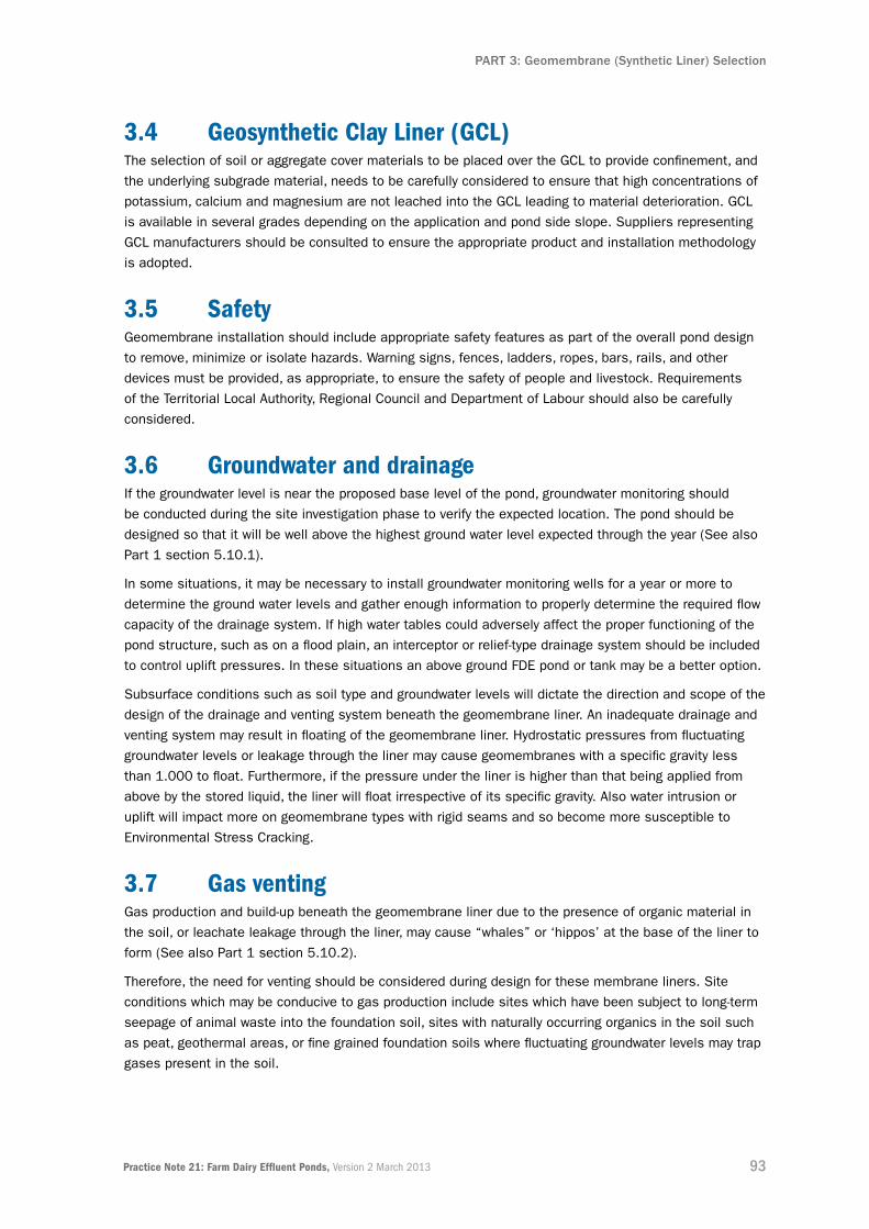
93Practice Note 21: Farm Dairy Effluent Ponds, Version 2 March 2013
PART 3: Geomembrane (Synthetic Liner) Selection
3.4 geosynthetic Clay Liner (gCL)The selection of soil or aggregate cover materials to be placed over the GCL to provide confinement, and
the underlying subgrade material, needs to be carefully considered to ensure that high concentrations of
potassium, calcium and magnesium are not leached into the GCL leading to material deterioration. GCL
is available in several grades depending on the application and pond side slope. Suppliers representing
GCL manufacturers should be consulted to ensure the appropriate product and installation methodology
is adopted.
3.5 safetyGeomembrane installation should include appropriate safety features as part of the overall pond design
to remove, minimize or isolate hazards. Warning signs, fences, ladders, ropes, bars, rails, and other
devices must be provided, as appropriate, to ensure the safety of people and livestock. Requirements
of the Territorial Local Authority, Regional Council and Department of Labour should also be carefully
considered.
3.6 groundwater and drainageIf the groundwater level is near the proposed base level of the pond, groundwater monitoring should
be conducted during the site investigation phase to verify the expected location. The pond should be
designed so that it will be well above the highest ground water level expected through the year (See also
Part 1 section 5.10.1).
In some situations, it may be necessary to install groundwater monitoring wells for a year or more to
determine the ground water levels and gather enough information to properly determine the required flow
capacity of the drainage system. If high water tables could adversely affect the proper functioning of the
pond structure, such as on a flood plain, an interceptor or relief-type drainage system should be included
to control uplift pressures. In these situations an above ground FDE pond or tank may be a better option.
Subsurface conditions such as soil type and groundwater levels will dictate the direction and scope of the
design of the drainage and venting system beneath the geomembrane liner. An inadequate drainage and
venting system may result in floating of the geomembrane liner. Hydrostatic pressures from fluctuating
groundwater levels or leakage through the liner may cause geomembranes with a specific gravity less
than 1.000 to float. Furthermore, if the pressure under the liner is higher than that being applied from
above by the stored liquid, the liner will float irrespective of its specific gravity. Also water intrusion or
uplift will impact more on geomembrane types with rigid seams and so become more susceptible to
Environmental Stress Cracking.
3.7 gas ventingGas production and build-up beneath the geomembrane liner due to the presence of organic material in
the soil, or leachate leakage through the liner, may cause “whales” or ‘hippos’ at the base of the liner to
form (See also Part 1 section 5.10.2).
Therefore, the need for venting should be considered during design for these membrane liners. Site
conditions which may be conducive to gas production include sites which have been subject to long-term
seepage of animal waste into the foundation soil, sites with naturally occurring organics in the soil such
as peat, geothermal areas, or fine grained foundation soils where fluctuating groundwater levels may trap
gases present in the soil.

94 Practice Note 21: Farm Dairy Effluent Ponds, Version 2 March 2013
PART 3: Geomembrane (Synthetic Liner) Selection
Lining with gas vent.
3.8 Drainage and venting system designTo facilitate collection, drainage of liquids and venting of gas, geosynthetics such as a geonet or
geocomposite under the geomembrane liner should be installed to the manufacturer’s recommendations.
The cut pond base should be sloped, typically a minimum of 2 per cent, to permit positive flow of the
liquids or gases. In most cases, the geocomposite will serve both drainage and venting purposes. In
very large ponds the base may need to be sloped in multiple directions in order to decrease the required
drainage and venting flow travel distances. The drainage system should also incorporate a leak-detection
system and this is recommended beneath all pond lining materials.
3.9 PenetrationsThe number of penetrations through a geomembrane lining needs to be minimized. Trenching and
backfilling of fill around pipes should be carefully detailed so that subsurface water is not able to
flow along the outside of the pipe and down the underside of the geomembrane. Mechanical pipe
penetrations and filter collars should be considered. A correctly designed concrete slab around the
pipe can be installed to reduce differential settlement along the pipe and reduce a potential weak point
around the pipe penetration area.
3.10 stirrersIf stirrer or agitation operations are likely to result in abrasion or other mechanical damage to the
liner, then protective measures should be provided to ensure the integrity of the lining. Options include
increasing the geomembrane liner thickness above the minimum values recommended, or providing
protective pads and aprons at agitation locations. A concrete pad laid upon sacrificial offcuts of
geomembrane and underliner is a good option as it acts as both ballasting and diffuses abrasive grit
agitated by the stirrer.

95Practice Note 21: Farm Dairy Effluent Ponds, Version 2 March 2013
PART 3: Geomembrane (Synthetic Liner) Selection
3.11 Quality assurance and warrantiesIt is important that the geomembrane installer prepares a site specific work plan (also known as a
Project Quality Plan) which details the full scope of the installation work to be undertaken. A copy of
this plan should be supplied to the farm owner or their representative for acceptance prior to work
commencement.
During the project, supporting or confirming documentation for all lining materials supplied and
incorporated into the works needs to be gathered. The installers documentation needs to cover all
sampling, testing, inspection, and proving of compliance with relevant standards.
At contract completion, and as a contract condition, the following documentation should be supplied by
the installer, to the owner or the Suitably Qualified Person (SQP) to review:
▪ Certificate(s) from the geomembrane manufacturer confirming full QA compliance with the relevant, approved GRI test specification for the batch from which the installed geomembrane was supplied
▪ Site records, including installer subgrade acceptance, panel numbering and placement, trial welds and seam tests, and other supporting QA documentation
▪ Material warranty for a minimum period of 20 years from the geomembrane supplier, which has been approved by the manufacturer for the stated period prior to installation
▪ Installation (workmanship) warranty from the geomembrane installer for a minimum period of 5 years
▪ Certification by the installer that they have completed their work to the drawings, specifications and any other relevant documents. This certification usually takes the form of a signed Producer Statement, for example NZS3910 Sixth Schedule: Form of Producer Statement – Construction.

96 Practice Note 21: Farm Dairy Effluent Ponds, Version 2 March 2013
PART 3: Geomembrane (Synthetic Liner) Selection
4.0 summaryThere are many factors that contribute to good geomembrane performance, and these are
summarised in the table below.
geoMeMBrane suCCess faCtors
Material ▪ Choose a geomembrane with attributes that are suited to the site conditions
▪ Confirm sufficient UV and ozone-resistance provided to suit New Zealand conditions
▪ Confirm resistance to long-term environmental stress cracking
▪ Assure material will not overstretch creating weaknesses
▪ Secure manufacturer’s certification that product meets GRI specifications
▪ Secure material warranty from the manufacturer for the batch supplied.
site ▪ Ensure stable-cut side slopes that provide long-term stability
▪ Ensure distance from subsurface organic materials that can form gas
▪ Construct pond base above highest likely ground water level
▪ Install subsoil drainage.
design ▪ Select competent subgrade construction materials
▪ Develop clear specification for materials requirements
▪ Design for protection against weather extremes
▪ Mitigate stress fatigue and cracking
▪ Include a leak detection system.
Construction ▪ Engage experienced contractors and installers
▪ Confirm subgrade compaction meets specification
▪ Ensure subgrade surface is sufficiently trimmed and smoothed
▪ Confirm anchoring details meet designer’s specifications
▪ Ensure approved sealing around pipes and other penetrations
▪ Adopt manufacturer-recommended jointing/seaming system
▪ Prepare ‘as-built’ plans.
quality assurance
▪ Approve Quality Assurance (QA) programme prior to installation
▪ Complete on-site inspection/testing Quality Control (QC) procedures
▪ Documentation reviewed by a Suitably Qualified Person (SQP)
▪ Installer provides an installation (workmanship) warranty.
operations ▪ Arrange for regular inspection and maintenance
▪ Have clearly documented cleaning out procedures (if required)
▪ Have procedures for damage repair, including patching repairs
▪ Consult supplier on chemicals and substances which may affect performance
▪ Protect from possible vandalism, stock and other damage causes.
Table 4.1: Factors Contributing to Successful Geomembrane Performance

Ponds and tanks on Peat


99Practice Note 21: Farm Dairy Effluent Ponds, Version 2 March 2013
PART 4: Ponds and Tanks on Peat
1.0 introduction1.1 PurposeFarm Dairy Effluent (FDE) ponds and tanks constructed over peat soils can have an increased
performance risk due to the weak and compressible nature of the underlying peat soils.
Anecdotal reports suggest that pond and tank failures on peat have contributed to a climate in which
farmers may be reluctant to construct and install dairy effluent storage on their properties.
While tanks and pond embankments may be constructed over peat using procedures and methods
outlined in Part 1 of this Practice Note (PN), the engineering properties of peat are such that there needs
to be a “step up” in the level of ground investigation and detailed design undertaken. This is necessary
to ensure that the long-term integrity and successful performance of these FDE containment and storage
facilities are comparable to those constructed over sand, clay and silt soils.
The purpose of this document is to explain the need for this increased level of investigation and
design work, and to give some guidance on the choice of investigative techniques appropriate for the
intended storage facility type. It is also to identify the issues that need to be considered when choosing
construction methods, ancillary works, and the operation of facilities on peat soils. This document is not
intended to give design advice, rather to highlight design issues that may need to be addressed by the
designer and should be read in conjunction with the rest of the Practice Note.
Key Points
Ponds and tanks constructed on peat soils provide different engineering challenges to those
constructed on other soils:
▪ Varying rates of settlement across a structure can lead to differential settlement
▪ Ground settlement can continue over many years
▪ Ponds and tanks should be constructed above ground
▪ Gas venting and drainage collection is critical
▪ Clay and reinforced concrete liners are not considered suitable
▪ A “step-up” in ground investigations and design is required
▪ Specialist engineering testing and designer inputs are essential
▪ Design options are available to reduce settlement and performance risks
▪ There may be higher long-term maintenance costs that need to be allowed for

100 Practice Note 21: Farm Dairy Effluent Ponds, Version 2 March 2013
PART 4: Ponds and Tanks on Peat
1.2 what is Peat?Peat is not a single soil material. It is a highly variable material that can exhibit considerable changes in
composition and nature over short distances and depths.
There are several definitions including:
“A mixture of fragments of organic materials derived from vegetation that has been chemically changed and
partly fossilised”, and “Dead vegetation in various stages of decomposition”.
Several engineering classifications for peat soils have been adopted reflecting the difficulty in precisely
describing and assessing the engineering properties of peat soils.
However, a simplified approach is proposed in which peat is classified into three broad categories based
on the presence of roots and other organic fibres within the peat:
▪ Thick (Coarse) Fibrous Peat (Fibres >1mm thick)
▪ Thin (Fine) Fibrous Peat (Fibres <1mm thick)
▪ Amorphous Peat (No fibres)
Fibrous peat is generally stronger than amorphous peat, sometimes significantly so. The fibrous crust at
the ground surface is often the strongest part of the soil profile in peats.
Peat deposits are typically associated with swamp or bog development in low lying water areas. Many
show development profiles similar to that illustrated in Figure 1.1 below.
Figure 1.1: Peat Profile in Swamp/Bog Development
The thicknesses and lateral distribution of the three types of peat present can vary and the inflow
of streams can result in accumulation of layers of sand, silt and clay within the peat.

101Practice Note 21: Farm Dairy Effluent Ponds, Version 2 March 2013
PART 4: Ponds and Tanks on Peat
For example, a 5-metre-deep peat profile can contain as little as 300
millimetres of soil minerals and organic matter, the rest effectively being
4.7 metres of water held in a sponge-like matrix of decaying vegetation and
fibres, and soil particles. By comparison a 5-metre-deep silty clay profile
would contain virtually the full 5-metre depth in soil minerals and organic
matter.
The figure along side shows typical near surface fibrous peat. Note the
rotation of the fibres from vertical to horizontal towards the base of the
photograph. These fibres reinforce the soil lending the peat greater strength
than the soil matrix has alone.
In general terms, the strength of peat decreases as the number and
thickness of fibres also decreases.
1.3 why is Peat a Challenge?There are a number of reasons why peat can present challenges to construction:
▪ Peat exhibits many of the same physical properties as other soils such as silt and clay, but it does so to greater extremes
▪ All soils settle under loadings from pond embankments and tanks, but peat is highly compressible; settlements are potentially much greater and can continue for much longer periods than most other soil types
▪ Peat can be very weak as well as highly compressible. Paddocks often consist of a relatively strong surface crust which overlies much weaker softer peat below; and if excavation and construction breaks through this crust, the benefits the crust provides can be lost
▪ Peat soils are typically associated with shallow groundwater and areas of land where winter groundwater levels are frequently at, or close to, ground level. This means excavations can flood quickly and the sides of excavations can become unstable
▪ Peat soils can be comprised mainly of water with very little organic or mineral content. They may contain minimal actual ‘solid’ material, the rest being water and gas
▪ The natural variation in peat composition means that each location is different. Variation within the peat beneath a large structure, such as a large diameter tank or pond, may result in parts of the structure experiencing different degrees of settlement. This process is known as differential settlement and can have serious detrimental effects on built structures
▪ Existing ponds on peat cannot be simply cleaned out and a new liner installed. In many cases, existing ponds that have been excavated into peat are unlined and the effectiveness of their effluent containment is questionable. There are significant health and safety risks associated with entering into these ponds, as well as major engineering issues associated with trying to install a suitable liner. Issues are likely to include: groundwater inflow, hydraulic uplift of all liner types, soft compressible soils against which a clay liner cannot be compacted, and unstable sides to the excavation
▪ Extensive investigations are required to confirm, or otherwise, the continued suitability of a site. Subsequent site specific pond design analysis is required to confirm that the necessary performance from the structure can be expected over its design life
▪ Investigations need to extend to at least the full thickness of the peat, or to twice the width of the pond bank or diameter of the tank. This is because the loading from the tank or bank is exerted by the soil to this depth as illustrated below in Figures 1.3 and 1.4. Peat soils can still be highly compressible even when buried to significant depth.
Figure 1.2: Fibrous Peat

102 Practice Note 21: Farm Dairy Effluent Ponds, Version 2 March 2013
PART 4: Ponds and Tanks on Peat
Figure 1.3: Stress Zones Imposed in Soil by Circular Tanks
Figure 1.4: Stress Zones Imposed in Soils by Embankments or Bunds

103Practice Note 21: Farm Dairy Effluent Ponds, Version 2 March 2013
PART 4: Ponds and Tanks on Peat
2.0 engineering Properties of Peat2.1 engineering issues with Construction on PeatThe key issues that need to be addressed in the design and construction of FDE ponds or tanks
on peat are:
▪ Bearing capacity failure
▪ Excessive settlement of the structure
▪ Shallow groundwater table
▪ Gas collection.
While these issues need to be addressed for construction on all soils, the risks are greater on peat due
to its soft and highly compressible nature.
In all cases these issues can only be suitably addressed if an appropriate minimum level of ground
investigation is carried out as part of the design process.
2.2 Bearing Capacity failureBearing capacity failures are caused when the load from a structure, such as from a tank (Figure 2.1)
or pond embankment (Figure 2.2), is too much for the soils to support without shearing and giving way
under the structure.
General failure Local failure
Figure 2.1: Bearing Capacity Failure Beneath Tanks

104 Practice Note 21: Farm Dairy Effluent Ponds, Version 2 March 2013
PART 4: Ponds and Tanks on Peat
Figure 2.2: Bearing Capacity Failure of Pond Embankment
The shear strength of a soil is the measure of its resistance to failing by shearing or sliding under a load.
Peat is one of the few soils whose shear strength generally decreases with depth. The way to avoid these
failures occurring is to measure the shear strength profile of the underlying soils and ensure the stresses
imposed by the tank or embankment do not exceed the soil’s strength.
The generally unnecessary practice of installing shear key trenches beneath pond embankments may
increase the risk of a bearing capacity failure on peat soils. Cutting through the stronger crust at the
surface of the peat can reduce its integrity as a consequence.
2.3 excessive settlementAll soils settle under loading, but settlements are potentially greater with peat. The key issue is to
understand and forecast the amount and rate of settlement that will occur over the lifetime of the tank or
pond. This is so possible changes in level and shape of the pond or tank can be allowed for in the design
process.
The expulsion of water and gas from the soil fabric under the new loading from the tank or pond
embankment allows the soil fabric to “close up” causing the ground surface to settle in consequence.
This process is known in engineering as consolidation and is equivalent to “shrinkage” in soil science.
Excessive settlement can over-stress and potentially damage liners, disrupt pipe connections, and result
in loss of freeboard and capacity in ponds.
Similarly, differential settlement, when one part of the structure settles more than the rest, can cause
damage to fixtures and fittings and result in loss of freeboard and capacity in storage structures.
There are two phases of soil consolidation or settlement: a rapid primary phase, and a longer-term,
slower secondary phase.
A key difference in settlement characteristics demonstrated by peat over other soils is that the
secondary phase does not end. It continues at a constant rate regardless of how heavy the tank or pond
embankment is.
The level and rate of the two settlement phases can be estimated from soil test data. This enables
the design engineer to allow for the potential effects of these settlement phases in the design and
construction of a tank or pond.

105Practice Note 21: Farm Dairy Effluent Ponds, Version 2 March 2013
PART 4: Ponds and Tanks on Peat
2.4 shallow groundwater tableMost excavations into peat soils will encounter groundwater at shallow depth. This depth may vary
seasonally, being deeper after the drier summer months than in winter.
Groundwater flow into an excavation has a number of significant effects, including:
▪ Flooding of the excavation requiring pumping out, disposal and possible treatment of the water prior to discharge
▪ Softening and liquefying soils in the base and sides of the excavation
▪ Weakening and potentially collapsing sides of the excavation
▪ Lowering groundwater around the excavation, causing settlement of the ground level around
▪ the excavation possibly over tens-of-metres distance.
Figure 2.3: Effects of Excavating Below Groundwater
All of these factors increase the difficulty of working in the excavation and can significantly add to the
cost of the works. In order to avoid these difficulties, pond and tank construction should be above
ground, or ideally moved to a location without these issues.

106 Practice Note 21: Farm Dairy Effluent Ponds, Version 2 March 2013
PART 4: Ponds and Tanks on Peat
2.5 gas CollectionThe natural degradation of the organic material in peat generates gases, usually methane or carbon
dioxide depending on local conditions. If not free to vent to the atmosphere, these gases can collect
beneath lining membranes, generating ‘hippos’ as seen in the photograph below.
Hippo formation due to gas collection
This can be prevented by the installation of gas venting measures beneath a synthetic liner (also known as a geomembrane). However, these venting measures need to be kept dry to operate efficiently and for this reason may be designed to double as a drainage vent if an under-drainage system is installed.

107Practice Note 21: Farm Dairy Effluent Ponds, Version 2 March 2013
PART 4: Ponds and Tanks on Peat
3.0 settlement3.1 Managing settlementA first step during the design phase in managing settlement is to reduce the actual volume of storage
required to a minimum. The Dairy Effluent Storage Calculator (DESC) provides a valuable tool in the
hands of an experienced designer to achieve this (See also Part 1 section 5.6 on pond sizing for further
background). The design of the FDE pond or tank should not be undertaken in isolation of reviewing the
whole effluent system. Reduced storage requirements may be possible through factors such as:
▪ Adopting a low rate application system, which allows irrigation to continue through times when high rate systems are not desirable
▪ Irrigating to low risk soil areas
▪ Reducing storage inflows through dry scraping and low water-pressure yard washing, and water recycling such as green wash systems
▪ Diverting unused shed roof and yard area rainwater away from the effluent storage collection system
Settlement on peat can be extreme and the aim of managing the settlement is to limit it to a level less
than that at which damage could occur to a pond or tank. A number of technical means are available to
achieve an acceptable level of settlement, although the small scale nature of individual ponds and tanks
often makes it prohibitively expensive.
Never the less there are two common approaches that may be considered:
▪ If the peat is thin enough, it may be possible to excavate and remove it from beneath the footprint of the tank or pond, or;
▪ Preloading of the ground surface. This removes the majority of the settlement prior to pond or tank installation.
Other means of managing small settlements are to adopt construction techniques and materials that can
best cope with the deformations and stresses that settlement will impose. For example, geomembranes
(also known as synthetic liners) have some advantage due to their flexibility and ease of extending and
repairing if necessary; whereas, clay and reinforced concrete liners are not considered suitable as they
are usually unable to withstand the imposed forces. The selection of the appropriate synthetic liner
material is the role of the design engineer. They should be able to estimate the degree of settlement
and, in particular, differential settlement that could give rise to deformation and liner stretching. Similarly,
pond anchor trenches for synthetic liners must also be properly designed and constructed. Part 3 of this
Practice Note provides further guidance.
Settlement of the pond banks may result in progressive “crowning” where the base of the pond rises
relative to the sides as illustrated in Figure 3.1. However, subsequent levelling of the peat base by
excavating is likely to result in very soft wet peat being exposed following removal of the crust, thereby
making installation, or reinstallation, of the synthetic liner very difficult. The design engineer should also
consider the loss of storage capacity and freeboard as a consequence of leaving the crown in place.

108 Practice Note 21: Farm Dairy Effluent Ponds, Version 2 March 2013
PART 4: Ponds and Tanks on Peat
Figure 3.1: Settlement of Pond Banks and Crowning of Pond Centre
3.2 Pond Bank settlementAs the largest and heaviest part of the pond structure, pond banks will be the area of the pond in
which the majority of settlement will be generated.
As previously described there are two phases of settlement, primary and secondary, and these are
illustrated in an example in Figure 3.2.
In this theoretical example, the ground on which a 2-metre-high bank has been formed, will settle
approximately 750 millimetres in 35 days and 1,000 millimetres after 10,000 days (27 years). If the
predicted, remaining long-term settlement of 250 millimetres after 35 days has elapsed is acceptable
to the pond designer, then the pond can be lined and completed after that time.
Figure 3.2: Calculated Settlement of a Two-Metre-High Bank (Example Only)
If this approach will not reduce the settlement sufficiently, the designer may consider preloading the
ground by constructing a higher, heavier bank to speed the primary settlement, and subsequently remove
the extra fill height once 1,000 millimetres of settlement has occurred. The effect of this is shown in
Figure 3.3 below.

109Practice Note 21: Farm Dairy Effluent Ponds, Version 2 March 2013
PART 4: Ponds and Tanks on Peat
Figure 3.3: Effect of Preloading (Example Only)
In this example of preloading for a 5-metre-high bank, 1,000 millimetres of settlement will occur in the
first 30 days. If the bank is then reduced by 2 metres in height to the finished design height of 2 metres
above original ground level (the base having settled 1 metre into the ground 3 metres of fill is needed
to achieve the 2 metres height above original level), no further settlement can be expected over the next
25 years.
However, there will be a cost to achieve this which will need to be allowed for in the earthworks budget.
Specifically, the cost of excavating from a borrow source, placing three metres of additional but temporary
fill to the bank, then subsequently removing two metres of it and placing it elsewhere.
3.3 tank settlementLike banks, tanks will settle on first construction following the primary and secondary pattern described
above. In general the degree of settlement from a tank is expected to be less than that of a pond bank
as it is a lighter structure.
However, differential settlement around the tank circumference and across the diameter needs to be
assessed by the design engineer and consequential stress and strain on liner and tank components
allowed for. Standard tank designs will generally cope with a predetermined level of deformation, but the
likelihood of deformation beyond that needs to be assessed for the proposed site by the design engineer.
Where excessive settlement or deformation of the tank is likely, preloading the tank site and building the
tank on an engineered fill platform is recommended.
3.4 settlement During useBoth ponds and tanks will experience further settlement on filling. Each time a pond or tank is filled,
settlement will follow the primary/secondary pattern described above. The extent of settlement will be
related to the depth/weight of effluent, how long the pond is filled, the size of the pond/tank, and the
nature of the underlying peat. In general terms, the cyclic filling and emptying of the pond or tank will
generate further settlement in a series of steps over the lifetime of the pond.

110 Practice Note 21: Farm Dairy Effluent Ponds, Version 2 March 2013
PART 4: Ponds and Tanks on Peat
4.0 ground investigation, Depths and Methods4.1 scope of investigation In comparison to most other soil types, the properties of peat soils require a “step-up” in the level
of ground investigation required. The key issues that need to be determined by a ground investigation
on peat are:
▪ Peat thickness
▪ Peat strength
▪ Peat compressibility
▪ Groundwater level.
Before undertaking any ground investigation, a desktop study of available data should be completed
to optimise the onsite ground investigation process.
This should include, but not be limited to:
▪ Inspection of published geological and soil maps
▪ Examination of any local water bore records (these are sometimes held by Regional Councils)
▪ Examination of published papers.
From this information the appropriate scope and depth of investigation can be determined.
A minimum of three exploratory holes is recommended, located evenly around the perimeter of the
proposed tank or pond. This allows interpretation of ground conditions between exploratory holes and
beneath the proposed tank or pond. Any variation in peat thickness and consistency across the site
should be identified and any consequential risk of differential settlement considered
4.2 Depth of investigation Tanks and ponds impose loads on soils to a depth equivalent to the diameter of the tank, and width
of the pond. As a minimum the investigation should therefore penetrate the full depth of the peat, or
to twice the width of the proposed tank or pond embankment, whichever is the shallower.
Care is needed to ensure that the true base of the peat is reached. Many peat deposits are inter-layered
with sand and silt soils which can be mistaken for the base of the peat deposit.

111Practice Note 21: Farm Dairy Effluent Ponds, Version 2 March 2013
PART 4: Ponds and Tanks on Peat
4.3 MethodsIn very thin peat deposits of up to three metres, investigations by test pitting and field testing,
supplemented by scala penetrometer and hand shear vane testing, may be sufficient (See also Part 2
section 3 for investigation and testing).
In thicker peat deposits the following methods of investigation should be undertaken.
4.3.1 Cone PenetroMeters (CPt)In thicker deposits, Cone Penetrometer Tests (CPT) and/or boreholes are needed to determine the peat
properties over the depths of soil concerned.
Typically the CPT is carried out from a truck or track mounted rig (Figure 4.1). The CPT itself is a rod fitted
with a cone tip that is pushed vertically into the ground at a constant rate. The penetration resistance
encountered and the friction on the side of the cone is recorded by pressure and strain gauges fitted to
the rods. By comparing the penetration resistance of the cone to the side friction, the soil type and soil
strength can be determined continuously by depth. The results are presented as a series of graphs which
aid their interpretation (Figure 4.2).
By using a cone fitted to the rod, water pressures are measured as it passes through the soil. The test
can be stopped and the time taken for pore water pressure to fall to a background level determined. This
is a ‘pore water dissipation test’ and the results can be used to aid assessment of the rate of settlement.
The CPT tests can be further supplemented by undertaking a limited number of hand shear vane tests in
the upper one metre of the soil to aid assessment of the stronger soil crust.
Overall CPTs offer a cost effective means of assessing peat strength and compressibility, but as no
samples are obtained, the speed and degree of settlement cannot be determined as accurately as by
using samples obtained from a borehole.
Figure 4.1: Truck and Track-Mounted CPT Vehicles

112 Practice Note 21: Farm Dairy Effluent Ponds, Version 2 March 2013
PART 4: Ponds and Tanks on Peat
Figure 4.2: CPT Results Showing Typical Raw Data for Thick Peat

113Practice Note 21: Farm Dairy Effluent Ponds, Version 2 March 2013
PART 4: Ponds and Tanks on Peat
4.3.2 BorehoLesWhilst CPT data can be used to estimate settlements, to fully define and obtain good estimates of likely
settlements, in particular the rate of settlement, laboratory testing of soil samples is necessary. The best
way to obtain these samples is from a borehole.
Boreholes allow core and tube samples to be obtained from depth that can then be tested for settlement
properties in a soil testing laboratory. They allow visual inspection of the soil materials, an assessment
of the fibre content and the selection of samples for testing, (Figure 4.3).
The primary soil laboratory test to determine settlement properties is an ‘oedometer consolidation test’.
The results of these tests can be used directly to estimate the rate and degree of primary and secondary
settlements on peat.
Moisture content and liquid limit tests can also be used to indirectly assess peat properties and aid
interpretation of the oedometer and CPT test results.
The use of oedometer test data should give the design engineer a greater level of confidence in the
assessment of peat properties than that based on data obtained from the CPT alone.
Oedometer tests are very important to gauge the rate of settlement and the timing of some key
construction decisions such as installation of liners or if staged construction is necessary.
If staged construction is considered necessary the test results are then used to assess how much
surcharge should be applied, and the timing of its removal.
Figure 4.3: Example of Thick Peat in a Borehole Core Sample Showing Variation with Depth
The core should be read as a book from top left to bottom right with ground level at the top and compared to the example CPT trace presented in Figure 4.2 which is from the same site. (Note the SILT at 10.50 m that could be mistaken for the base of the Peat, when there is another 5.85 m of compressible Peat below it.)
There is a silty CLAY at about 1-metre to 1.5-metre depth
Soft compressible Coarse Fibrous PEAT
Changing to Soft Fine Fibrous PEAT
Soft silty PEAT at about 9.5-metre depth
Soft to firm SILT at 10.50 m to 12.15 m
Very soft Amorphous PEAT – continues to 18-metre depth.

114 Practice Note 21: Farm Dairy Effluent Ponds, Version 2 March 2013
PART 4: Ponds and Tanks on Peat
5.0 Design Process and Considerations5.1 Cost and risk assessmentIt is important to recognise that some degree of settlement of tanks and ponds on peat is inevitable, but
that it can be reduced to manageable levels. Periodic future maintenance work related to settlement can
be forecast, planned and budgeted for.
At the investigation phase, with each “step-up” from basic test pitting to CPTs, through to boreholes and
laboratory testing, there is an increase in investigation cost but also an increase in the quality of the data
obtained for use in design. The relationship between costs and risk is illustrated in Figure 5.1.
Figure 5.1: Ground Investigation Relative Cost and Risk Comparison
A discussion of “cost versus benefits” between the designer and farmer is essential during the
investigation and design phases. This is to compare the cost of specific design and construction to
mitigate settlement, against the cost of maintenance work that will be required over the life of the pond if
this is not undertaken.
There is a wide range of possible variations in long-term maintenance costs. For example, annual topping
up of pond embankments with associated adjustment of liners and pipework, once every five or even ten
years. Maintenance costs can then be estimated and allowed for in the long-term farm business plan.

115Practice Note 21: Farm Dairy Effluent Ponds, Version 2 March 2013
PART 4: Ponds and Tanks on Peat
5.2 Design Process stepsFollowing the field investigation and laboratory testing of soil samples, tank and pond designers need to
finalise their designs using the following steps:
Step 1: From the information obtained from the ground investigation, designers need to calculate the
bearing capacity of the peat, and compare that to the loading imposed by the proposed pond
bank or tank.
If the peat cannot support the tank or pond without a shear failure occurring, the designer can
assess possible remediation measures, including:
▪ Locating the pond or tank elsewhere
▪ Excavating out the peat
▪ Reducing the size of the pond or tank
▪ Including ground improvement measures such as “geogrid” or other proprietary products.
Step 2: If the peat has sufficient bearing capacity, or after the design has been modified to meet the
site conditions, the designer needs to assess the rate and degree of settlement likely to
occur and compare this to the acceptable levels of settlement the proposed pond or tank can
tolerate. The options then available are:
▪ If the primary settlement phase is sufficiently rapid and the secondary phase settlement not excessive, it may be possible to install the pond or tank after the primary settlement is complete.
▪ If the time taken for primary settlement to be complete and/or the secondary settlement is excessive, look to take remedial actions such as:
▪ Locating the pond elsewhere
▪ Removing peat if possible
▪ Preloading
▪ Changing construction material. For example, considering light-weight fill or alternative liner type.
Step 3: Assess effects of settlement on ancillary works such pipes, pump locations and drainage:
▪ Settlement can cause disruption of pipes and a reduction in, or even reversal of, drainage pipe gradients. This could have serious effects on gravity feeds and drain effectiveness
▪ Pipe penetrations through liners may become areas of stress and deformation. They need to be minimised and preferably avoided
▪ Low points, including sumps, in ponds and tanks to which FDE falls can move and pump or intake/outfall locations may need relocation. Floating pumps may be a suitable alternative to avoid relocation. Alternatively, fixed pump locations with movable intake pipes may be adopted
▪ Gas mitigation and venting measures need to be installed beneath any flexible geomembrane liner. These need to be vented at high points around the edge of the pond and if crowning of the pond base is anticipated, additional central venting points should be considered
▪ The risk of gas collection beneath large diameter tanks should be assessed by the designer and mitigation measures included if necessary. This can comprise a central vent or permeable granular mat beneath the tank
▪ Surface water drainage around pond sides and tanks needs to be assessed. Settlement of the tank or pond may lead to the collection and ponding of surface water around it. Surface water channels and subsoil drains to cut off surface and subsoil water will generally be needed.

116 Practice Note 21: Farm Dairy Effluent Ponds, Version 2 March 2013
PART 4: Ponds and Tanks on Peat
6.0 summaryThe following flow charts summarise the investigation, design and construction process for tanks and
ponds on peat and supplement the process described in Part 1.
Figure 6.1: Flow Chart for Tanks on Peat
Figure 6.2: Flow Chart for Ponds on Peat
117Practice Note 21: Farm Dairy Effluent Ponds, Version 2 March 2013
PART 4: Ponds and Tanks on Peat
7.0 acknowledgementsFigure 1: Figure 1, N B Hobbs, Mire Morphology and the Properties and Behaviour of Some British
and Foreign Peats, Quarterly Journal of Engineering Geology, Vol 19, 1986.
Figure 3: Figure 3.1, N E Simons & B K Menzies, A Short Course in Foundation Engineering,
Butterworths, 1977
Figure 6: Figure 1.2: Groundwater Control Design and Practice, CIRIA C515, 2000
Acknowledgement is given for figures from the above sources that have been modified for this document.

118 Practice Note 21: Farm Dairy Effluent Ponds, Version 2 March 2013
PART 4: Ponds and Tanks on Peat


121Practice Note 21: Farm Dairy Effluent Ponds, Version 2 March 2013
referencesoVerViewA selection of documents have been reviewed in preparing this Practice Note covering consenting,
investigations, design, construction, and operation of FDE ponds.
This section provides a brief summary and links to relevant documents available.
Part 1: Design anD ConstruCtion PrinCiPLes
LegislationBuilding Act 2004 No 72
www.legislation.govt.nz/act/public/2004/0072/latest/dlm306036.html?search=ts_act_building+act_
resel&p=1&sr=1
Building Amendment Bill (No 4)
www.legislation.govt.nz/bill/government/2011/0322/latest/DLM3957236.html
Building (Dam Safety) Regulations 2008 (SR 2008/208)
www.legislation.govt.nz/regulation/public/2008/0208/latest/DLM1382001.html
Health and Safety in Employment Act 1992 No 96
www.legislation.govt.nz/act/public/1992/0096/latest/DLM278829.html?search=ts_act_
health+and+safety_resel&p=1&sr=1
Resource Management Act 1991 No 69
www.legislation.govt.nz/act/public/1991/0069/latest/DLM230265.html?search=ts_act_
resource+management_resel&p=1&sr=1
Managing fDe
Environment CanterburyA Guide to Managing Farm Dairy Effluent
This is a guide booklet produced by Dexcel and Environment Canterbury to provide advice to farmers.
It covers all aspects of FDE management including storage ponds, and RMA issues for ponds.
www.ecan.govt.nz/publications/plans/canterburyeffluentbooklet.pdf
agresearchBest Practice Management of Farm Dairy Effluent in the Manawatu-Wanganui Region
This is a guide for FDE management to meet Horizons Regional Council’s rules. There is no reference to
dams or the BA.
www.envirolink.govt.nz/pagefiles/376/421-hzlc43.pdf

122 Practice Note 21: Farm Dairy Effluent Ponds, Version 2 March 2013
dairy australiaEffluent and Manure Database for the Australian Dairy Industry
This is a detailed and comprehensive code of all aspects of FDE management for Australian conditions.
Aspects of sections 2.4 (pond site investigations, p56–60) and 2.35 (pond design and construction,
p61–66) are relevant in New Zealand.
www.dairyingfortomorrow.com/index.php?id=48
dairynzEnvironment: Designing Or Upgrading Effluent Systems
Dairy NZ offers a suite of effluent related guidance documents.
http://resources.dairynz.co.nz/Resource/ListForDairyNZSite?pageid=2145869375
Farm Dairy Effluent (FDE) Design Code of Practice
The purpose of this document is to guide designers through the process of developing an FDE system,
from the initial site investigation through to commissioning of the final system. It provides a general
design approach, including lists of things that must be taken into consideration.
Farm Dairy Effluent (FDE) Design Standards
The purpose of this document is to provide a set of standards against which to assess the design of
individual FDE systems in New Zealand, and is intended to be used in conjunction with the FDE Design
Practice Note.
Farm Dairy Effluent (FDE) Pond Design and Construction
A farmers guide to building a new effluent storage pond. This guide aims to help farmers through the
process and various factors to consider when building a new effluent pond.
Farm Dairy Effluent Systems: Planning the right system for your farm
This booklet helps the principal ask the right questions to get the right advice and service and so will
result in the most appropriate FDE system being installed.
Farmfacts: Farm Infrastructure
Guidance on other related farm infrastructure:
Tracks and races (8-1)
Feed pads - design and construction (8-2)
Feed pads - management and maintenance (8-3)
Stand-off pads - design and construction (8-4)
Stand-off pads - management and maintenance (8-5)
Covered pads and barns (8-6)
Road underpasses (8-7)
Building culverts and bridges (8-8)
PonD Design anD ConstruCtion
dairy nzA tool to assist in calculation the working volumes and true dimensions of FDE ponds and tanks.
www.dairynz.co.nz/page/pageid/2145866686?resourceId=748
Environment Bay of PlentyThe following document reviews the use of seepage collars in small dams and proposes adopting filter
collars and discontinuing with seepage collars.
www.boprc.govt.nz/media/33310/report-060900-reviewuseseepagecollarsinsmalldams.pdf

123Practice Note 21: Farm Dairy Effluent Ponds, Version 2 March 2013
Environment southlandEnvironment Southland has a number of very useful documents available on their website.
www.es.govt.nz/environment/farming/
Code of Practice for Design and Construction of Agricultural Effluent Ponds
A manual for pond owners and construction personnel specifically focused on pond construction.
www.es.govt.nz/download.aspx?f=/media/8617/code-of-practice-for-design-and-construction-of-
agricultural-effluent-ponds.pdf
Design and Construction of Storage Ponds
This two-page document is intended for contractors and farmer to explain the basics of storage pond
design and construction.
www.es.govt.nz/media/5899/design-and-construction-of-storage-ponds.pdf
institution of Professional Engineers new zealandIPENZ Practice Note 08: Engineers and Ethical Obligations
This Practice Note describes the ethical obligations engineers have to clients, other engineers,
and the public.
www.ipenz.org.nz/ipenz/forms/pdfs/pn08_ethical_obligations.pdf
IPENZ/ACENZ Short Form Agreement for Consultant Engagement
This is a recommended standard contract form between a consultant and a client, including model
conditions of engagement. There is space to include scope and nature of services, programme for
the services, fees and timing of payments, information or services to be provided by the client, and
variations to the conditions of engagement.
www.ipenz.org.nz/ipenz/practicesupport/endorsedinfo/
IPENZ/ACENZ Producer Statements
www.ipenz.org.nz/ipenz/practicesupport/endorsedinfo/
Construction Monitoring Services
Five levels of construction monitoring service are defined with the decision as to which level is
appropriate being project-dependent. Nominating a level at project commencement assists in providing
an agreed understanding as to the expected level of monitoring for the principal and the engineer.
www.ipenz.org.nz/ipenz/practicesupport/endorsedinfo/codes/
Ministry of Business, innovation and EmploymentLarge Dams
This describes the dam safety scheme and provides guidance for RAs and owners of large dams.
www.dbh.govt.nz/dam-safety-scheme-navigating
www.dbh.govt.nz/userfiles/file/publications/building/building-act/dam-safety-scheme-guidance-for-
regional-authorities-and-owners-of-large-dams.pdf
This web page provides details for the proposed amendments to the Dam Safety Scheme.
www.dbh.govt.nz/ris-dam-safety-scheme
Small Dams and the Building Code: Guidance for Regional Authorities, Contractors and
Owners of Small Dams
This assists owners of small dams in understanding how the construction of small dams relates to
the Building Code. This document is an explanatory note on how you should consider the Building Code
when building a (small) dam.
www.dbh.govt.nz/small-dams-guidance

124 Practice Note 21: Farm Dairy Effluent Ponds, Version 2 March 2013
Industrial Liquid Waste
This is the compliance document for clause G14 of the Building Code relating to industrial liquid waste.
It quotes the relevant clauses from the Building Code contained in the first schedule of the Building
Regulations 2005. The document describes the requirements to be satisfied by specific design for systems
used for the collection, storage, treatment, and disposal of industrial liquid waste.
www.dbh.govt.nz/UserFiles/File/Publications/Building/Compliance-documents/G14-industrial-liquid-waste-
2nd-edition-amendment-4.pdf
Safety from Falling
The compliance document for the New Zealand Building Code for establishing compliance where Safety
from Falling using barriers is contained in Clause F4 Safety from Falling – Third Edition (September 2007)
www.dbh.govt.nz/UserFiles/File/Publications/Building/Compliance-documents/F4-safety-from-falling.pdf
nelson, kdDesign and Construction of Small Earth Dams
Published by Inkata Press, Melbourne, ISBN 0 909605 34 3
new zealand geotechnical society Description of Soils and Rocks
This is a guideline for the field classification and description of soil and rock for engineering purposes.
www.nzgs.org/Publications/Guidelines/soil_and_rock.pdf
otago regional Council/new zealand Contractors FederationDesign and Construction of Agricultural Effluent Ponds
This document provides guidelines for contractors and design consultants, including details similar to the
Environment Southland document. Close similarities include permeability limits and a definition of SQPs.
www.orc.govt.nz/publications-and-reports/farming-and-land-management/dairy-farming/design-and-
construction-of-agricultural-effluent-ponds/
standards new zealandNZS 3910:2003 (Conditions of Contract for Building and Civil Engineering Construction)
This is the tried and proven form of contract for the design and construction of earthworks in New Zealand.
www.standards.co.nz/webshop/?action=viewsearchproduct&mod=catalog&pid=3910%3a2003%28nzs%29
&searchid=977833&searchorderingindex=1&searchsessionid=ee6f156425172e5418357e389418c376
the new zealand society on Large dams (nzsoLd)Guidelines on Inspecting Small Dams
These guidelines are intended to give a general overview of what to look for, and why, when inspecting a
small dam.
www.ipenz.org.nz/nzsold/guide001.pdf
united states Environmental Protection agency (us EPa)Designing and Installing Liners (Part IV Protecting Ground Water Chapter 7: Section B)
These guidelines on designing and installing liners provide technical considerations for ponds and
protecting groundwater from contamination and explores liners and leak detection systems.
www.epa.gov/osw/nonhaz/industrial/guide/pdf/chap7b.pdf

125Practice Note 21: Farm Dairy Effluent Ponds, Version 2 March 2013
Part 2: CLay Liners for PonDsLandfill Guidelines,
Centre of Advanced Engineering. (2000).
Christchurch, New Zealand: University of Canterbury Centre for Advanced Engineering.
“Full-scale hydraulic performance of soil-bentonite and compacted lay liners” Hardy Lecture,
Chapuis R, 2002, the 2000 R.M, Canadian Geotechnical Journal, Vol 39, pp 417 to 439.
Waste Containment Facilities, Guidance for Construction, Quality Assurance and Quality Control of
Liner and Cover Systems.
Daniel D.E. and Koerner R.M. (1995). New York, United States of America: American Society of
Civil Engineers.
Guideline for Hand Held Shear Vane Test
New Zealand Geotechnical Society (2001)
www.nzgs.org/Publications/Guidelines/shear_vane_guidelines.pdf
Soil Mechanics in Engineering Practice, 3rd Edition.
Terzaghi K, Peck R.B. and Mesri G. (1996). New York, United States of America: John Wiley & Sons.
Geotechnical Engineering in Residual Soils.
Wesley. (2010). Hoboken New Jersey, United States of America: John Wiley & Sons.
Part 3: geoMeMBrane (synthetiC Liner) seLeCtion
united states department of agriculture (usda), Pond Sealing or Lining Compacted Clay Treatment, Code 521D, September 2010, Natural Resources
Conservation Service, Conservation Practice Standard
http://www.nrcs.usda.gov/Internet/FSE_DOCUMENTS/stelprdb1046899.pdf
united states Environmental Protection agency (us EPa) United States Environmental Protection Agency (US EPA) Part IV Protecting Ground Water,
Chapter 7: Section B,
Designing and Installing Liners, Technical Considerations for New Surface Impoundments, Landfills,
and Waste Piles.
http://www.epa.gov/osw/nonhaz/industrial/guide/pdf/chap7b.pdf
geosynthetic institute GRI Specifications
http://www.geosynthetic-institute.org/specifications.htm
A Guide to Polymeric Geomembranes, a Practical Approach, Wiley Series in Polymer Science,
Scheirs, John
http://www.wiley-vch.de/publish/en/AreaOfInterestCE00/availableTitles/0-470-51920-7/

126 Practice Note 21: Farm Dairy Effluent Ponds, Version 2 March 2013


129Practice Note 21: Farm Dairy Effluent Ponds, Version 2 March 2013
appendix a – iPenz short forM agreeMent
Short Form Agreement for Consultant EngagementBetween:
........................................................................................................................................................ (Client)
and:
............................................................................................................................................................... (Consultant)
Collectively referred to herein as the “Parties” and individually as a “Party”
Project: Location:
Scope & nature of the Services:
Programme for the Services:
Fees & timing of payments:
Information or services to be provided by the Client:
The Client engages the Consultant to provide the Services described above and the Consultant agrees to perform the Services for the remuneration provided above. Both Parties agree to be bound by the provision of the Short Form Model Conditions of Engagement (overleaf), including clauses 2, 3, 9 and 10 and any variations noted below. Once signed, this agreement, together with the conditions overleaf and any attachments, will replace all or any oral agreement previously reached between the Parties.
Variations to the Short Form Model Conditions of Engagement (overleaf):
Client authorised signatory (ies):
Print name:
Date:
Consultant authorised signatory (ies):
Print name:
Date:

130 Practice Note 21: Farm Dairy Effluent Ponds, Version 2 March 2013 Page 2 March 2012
SHORT FORM MODEL CONDITIONS OF ENGAGEMENT
1. The Consultant shall perform the Services as described in the attached documents.
2. Nothing in this Agreement shall restrict, negate, modify or limit any of the Client’s rights under the Consumer Guarantees Act 1993 where the Services acquired are of a kind ordinarily acquired for personal, domestic or household use or consumption and the Client is not acquiring the Services for the purpose of a business.
3. The Client and the Consultant agree that where all, or any of, the Services are acquired for the purposes of a business the provisions of the Consumer Guarantees Act 1993 are excluded in relation to those Services.
4. In providing the Services the Consultant shall exercise the degree of skill, care and diligence normally expected of a competent professional.
5. The Client shall provide to the Consultant, free of cost, as soon as practicable following any request for information, all information in his or her power to obtain which may relate to the Services. The Consultant shall not, without the Client’s prior consent, use information provided by the Client for purposes unrelated to the Services. In providing the information to the Consultant, the Client shall ensure compliance with the Copyright Act 1994 and shall identify any proprietary rights that any other person may have in any information provided.
6. The Client may order variations to the Services in writing or may request the Consultant to submit proposals for variation to the Services. Where the Consultant considers a direction from the Client or any other circumstance is a Variation the Consultant shall notify the Client as soon as practicable.
7. The Client shall pay the Consultant for the Services the fees and expenses at the times and in the manner set out in the attached documents. Where this Agreement has been entered by an agent (or a person purporting to act as agent) on behalf of the Client, the agent and Client shall be jointly and severally liable for payment of all fees and expenses due to the Consultant under this Agreement.
8. All amounts payable by the Client shall be paid within twenty (20) working days of the relevant invoice being mailed to the Client. Late payment shall constitute a default, and the Client shall pay default interest on overdue amounts from the date payment falls due to the date of payment at the rate of the Consultant’s overdraft rate plus 2% and in addition the costs of any actions taken by the Consultant to recover the debt.
9. Where Services are carried out on a time charge basis, the Consultant may purchase such incidental goods and/or Services as are reasonably required for the Consultant to perform the Services. The cost of obtaining such incidental goods and/or Services shall be payable by the Client. The Consultant shall maintain records which clearly identify time and expenses incurred.
10. Where the Consultant breaches this Agreement, the Consultant is liable to the Client for reasonably foreseeable claims, damages, liabilities), losses or expenses caused directly by the breach. The Consultant shall not be liable to the Client under this Agreement for the Client’s indirect, consequential or special loss, or loss of profit, however arising, whether under contract, in tort or otherwise.
11. The maximum aggregate amount payable, whether in contract, tort or otherwise, in relation to claims, damages, liabilities, losses or expenses, shall be five times the fee (exclusive of GST and disbursements) with a maximum limit of $NZ500,000.
12. Without limiting any defences a Party may have under the Limitation Act 2010, neither Party shall be considered liable for any loss or damage resulting from any occurrence unless a claim is formally made on a Party within 6 years from completion of the Services.
13. The Consultant shall take out and maintain for the duration of the Services a policy of Professional Indemnity insurance for the amount of liability under clause11. The Consultant undertakes to use all reasonable endeavours to maintain a similar policy of insurance for six years after the completion of the Services.
14. If either Party is found liable to the other (whether in contract, tort or otherwise), and the claiming Party and/or a Third Party has contributed to the loss or damage, the liable Party shall only be liable to the proportional extent of its own contribution.
15. Intellectual property prepared or created by the Consultant in carrying out the Services (“New Intellectual Property”) shall be jointly owned by the Client and the Consultant. The Client and Consultant hereby grant to the other an unrestricted royalty-free license in perpetuity to copy or use New intellectual Property. Intellectual property owned by a Party prior to the commencement of this Agreement and intellectual property created by a Party independently of this Agreement remains the property of that Party. The ownership of data and factual information collected by the Consultant and paid for by the Client shall, after payment by the Client, lie with the Client. The Consultant does not warrant the suitability of New Intellectual Property for any purpose other than the Services or any other use stated in the Agreement.
16. The Consultant has not and will not assume any obligation as the Client’s Agent or otherwise which may be imposed upon the Client from time to time pursuant to the Health and Safety in Employment Act 1992 (“the Act”) arising out of this engagement. The Consultant and Client agree that in terms of the Act, the Consultant will not be the person who controls the place of work.
17. The Client may suspend all or part of the Services by notice to the Consultant who shall immediately make arrangements to stop the Services and minimise further expenditure. The Client and the Consultant may (in the event the other Party is in material default) terminate the Agreement by notice to the other Party. Suspension or termination shall not prejudice or affect the accrued rights or claims and liabilities of the Parties.
18. The Parties shall attempt in good faith to settle any dispute by mediation.
19. This Agreement is governed by the New Zealand law, the New Zealand courts have jurisdiction in respect of this Agreement, and all amounts are payable in New Zealand dollars.

131Practice Note 21: Farm Dairy Effluent Ponds, Version 2 March 2013
appendix B1 – forM of ProDuCer stateMent for: Design of farM Dairy effLuent PonDs
issuEd By (Design Firm)
to (Owner/Developer)
to BE suPPLiEd to (Consent Authority)
in rEsPECt oF (Description of Works)
at (Address)
(Design Firm) has been engaged by
(Principal)
to provide the following design services:
I (Suitably Qualified Person), a duly authorised representative of
(Design Firm)
(Qualifications)
CPEng
ETPract
IPENZ Member No
believe on reasonable grounds that the pond(s) when constructed in accordance with the drawings, specifications, and other documents provided or listed, will comply with the relevant codes and rules stated below.
IPENZ Practice Note 21: Code of Practice for the Design and Construction of Farm Dairy Effluent Ponds
(Relevant Codes and Rules)
(Signature of Authorised Representative)
(Date)
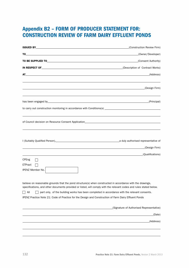
132 Practice Note 21: Farm Dairy Effluent Ponds, Version 2 March 2013
appendix B2 – forM of ProDuCer stateMent for: ConstruCtion reView of farM Dairy effLuent PonDs
issuEd By (Construction Review Firm)
to (Owner/Developer)
to BE suPPLiEd to (Consent Authority)
in rEsPECt oF (Description of Contract Works)
at (Address)
(Design Firm)
has been engaged by (Principal)
to carry out construction monitoring in accordance with Conditions(s)
of Council decision on Resource Consent Application
I (Suitably Qualified Person), a duly authorised representative of
(Design Firm)
(Qualifications)
CPEng
ETPract
IPENZ Member No.
believe on reasonable grounds that the pond structure(s) when constructed in accordance with the drawings, specifications, and other documents provided or listed, will comply with the relevant codes and rules stated below.
All part only, of the building works has been completed in accordance with the relevant consents.
IPENZ Practice Note 21: Code of Practice for the Design and Construction of Farm Dairy Effluent Ponds
(Signature of Authorised Representative)
(Date)
(Address)

133Practice Note 21: Farm Dairy Effluent Ponds, Version 2 March 2013
appendix B3 – forM of ProDuCer stateMent for: ConstruCtion of farM Dairy effLuent PonDs
issuEd By (Contractor)
to (Owner/Developer)
in rEsPECt oF (Description of Contract Works)
at (Address)
has contracted to (Contractor)
(Owner/Developer)
To carry out and complete works in accordance with a contract, titled
(Project)
(“the contract”)
I a duly authorised representative of
(Duly Authorised Agent)
(Contractor)
believe on reasonable grounds that has carried out and completed
(Contractor)
All Part only, as specified in the attached particulars of the works in accordance with the contract.
(Signature of Authorised Agent on behalf of)
(Date)
(Contractor)
(Address)
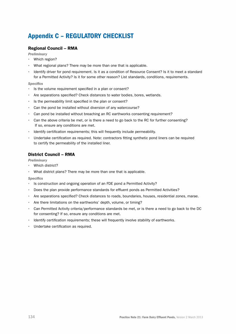
134 Practice Note 21: Farm Dairy Effluent Ponds, Version 2 March 2013
appendix C – reguLatory CheCKList
regional Council – rMaPreliminary ▪ Which region?
▪ What regional plans? There may be more than one that is applicable.
▪ Identify driver for pond requirement. Is it as a condition of Resource Consent? Is it to meet a standard for a Permitted Activity? Is it for some other reason? List standards, conditions, requirements.
Specifics ▪ Is the volume requirement specified in a plan or consent?
▪ Are separations specified? Check distances to water bodies, bores, wetlands.
▪ Is the permeability limit specified in the plan or consent?
▪ Can the pond be installed without diversion of any watercourse?
▪ Can pond be installed without breaching an RC earthworks consenting requirement?
▪ Can the above criteria be met, or is there a need to go back to the RC for further consenting? If so, ensure any conditions are met.
▪ Identify certification requirements; this will frequently include permeability.
▪ Undertake certification as required. Note: contractors fitting synthetic pond liners can be required to certify the permeability of the installed liner.
district Council – rMaPreliminary ▪ Which district?
▪ What district plans? There may be more than one that is applicable.
Specifics ▪ Is construction and ongoing operation of an FDE pond a Permitted Activity?
▪ Does the plan provide performance standards for effluent ponds as Permitted Activities?
▪ Are separations specified? Check distances to roads, boundaries, houses, residential zones, marae.
▪ Are there limitations on the earthworks’ depth, volume, or timing?
▪ Can Permitted Activity criteria/performance standards be met, or is there a need to go back to the DC for consenting? If so, ensure any conditions are met.
▪ Identify certification requirements; these will frequently involve stability of earthworks.
▪ Undertake certification as required.

135Practice Note 21: Farm Dairy Effluent Ponds, Version 2 March 2013
regional Council requirements for Effluent Ponds
region effLuent DisCharge to water
effLuent DisCharge to LanD
effLuent PonD size
seePage/ PerMeaBiLity
northland Yes* Permitted Recommend design criteria from Dairy and Environment Committee (DEC) manual (NRC can calculate this for you)
No more than minor contamination of groundwater by seepage
auckland Yes* Permitted Not specified but recommend use of DESC**
Ponds must be well constructed and sealed to prevent contamination of groundwater
Waikato Yes* Permitted Not specified but strongly recommend use of an accredited designer to calculate the pond size using DESC**
10-9 m/s
Bay of Plenty Yes* Controlled Recommend use of DESC**
Both renewal and new consents within the Rotorua Lakes catchment require ponds to be sealed to Pond Construction Practice Note standard. It is strongly advised that all new ponds are built to this standard.
taranaki Yes* Controlled Not specified for storage ponds
Not specified, but ponds must be sealed
Horizons No Controlled According to DESC**
Recommend that all effluent construction follows IPENZ PN21. Future discharge consents in the region will require this via a consent condition.
Hawke’s Bay No Controlled; discretionary in sensitive catchments
Recommend use of DESC**
10-9 m/s
Wellington No Controlled Not specified but recommend use of DESC**
Seepage to be imperceptible

136 Practice Note 21: Farm Dairy Effluent Ponds, Version 2 March 2013
region effLuent DisCharge to water
effLuent DisCharge to LanD
effLuent PonD size
seePage/ PerMeaBiLity
tasman district
Yes* Permitted Recommend use of DESC**
Any new/modified ponds have to be shown to meet the sealing standards of PN21
Marlborough district
No Permitted excluding the Wairau/Awatere catchment (Controlled)
Not specified Not specified
West Coast Yes* Permitted Effluent treatment–specified on a per number of cows basis.
For storage purposes – a minimum of 30 days is required
Can apply for a resource consent for seepage to groundwater providing special conditions are met
Canterbury No Controlled Must demonstrate adequacy, recommend use of the DESC**
Seepage rate: 10-8 m/s (1 mm/d)
otago No Permitted Not specified Storage system sealed to prevent seepage
southland No Controlled Recommend use of DESC**
Plans and specifications containing the information describing the proposed design and construction process to avoid adverse effects on water quality
* with consent
** DESC Dairy Effluent Storage Calculator
Note: this table is indicative rather than definitive and subject to change. In all instances, the rules of the
relevant regional/district council should be consulted directly.
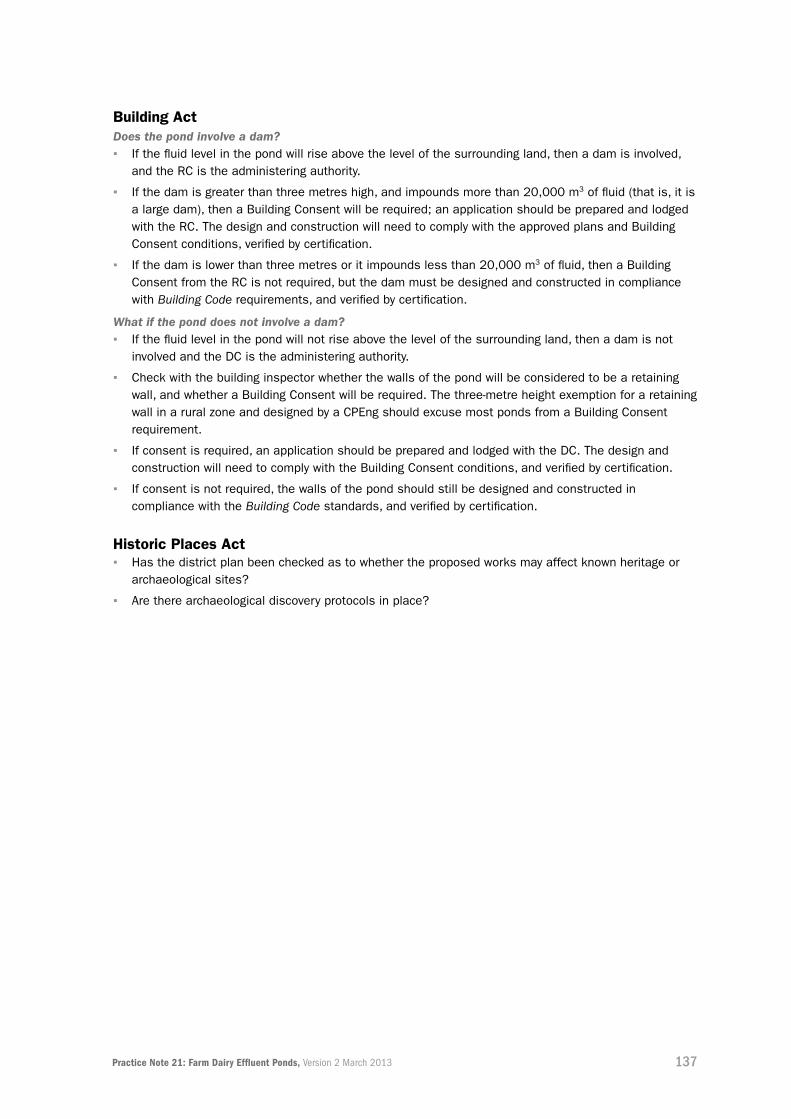
137Practice Note 21: Farm Dairy Effluent Ponds, Version 2 March 2013
Building actDoes the pond involve a dam? ▪ If the fluid level in the pond will rise above the level of the surrounding land, then a dam is involved,
and the RC is the administering authority.
▪ If the dam is greater than three metres high, and impounds more than 20,000 m3 of fluid (that is, it is a large dam), then a Building Consent will be required; an application should be prepared and lodged with the RC. The design and construction will need to comply with the approved plans and Building Consent conditions, verified by certification.
▪ If the dam is lower than three metres or it impounds less than 20,000 m3 of fluid, then a Building Consent from the RC is not required, but the dam must be designed and constructed in compliance with Building Code requirements, and verified by certification.
What if the pond does not involve a dam? ▪ If the fluid level in the pond will not rise above the level of the surrounding land, then a dam is not
involved and the DC is the administering authority.
▪ Check with the building inspector whether the walls of the pond will be considered to be a retaining wall, and whether a Building Consent will be required. The three-metre height exemption for a retaining wall in a rural zone and designed by a CPEng should excuse most ponds from a Building Consent requirement.
▪ If consent is required, an application should be prepared and lodged with the DC. The design and construction will need to comply with the Building Consent conditions, and verified by certification.
▪ If consent is not required, the walls of the pond should still be designed and constructed in compliance with the Building Code standards, and verified by certification.
Historic Places act ▪ Has the district plan been checked as to whether the proposed works may affect known heritage or
archaeological sites?
▪ Are there archaeological discovery protocols in place?

138 Practice Note 21: Farm Dairy Effluent Ponds, Version 2 March 2013
appendix D – PonD CertifiCation CheCKListThe following items detail the recommended test and inspection items for an SQP to be able
to certify a FDE pond.
1.1 testing at ConstruCtion CoMPLetionFor earthen embankment ponds:
▪ Bunds compacted sufficiently, as confirmed by testing
▪ All unsuitable in situ material removed during construction
▪ Correct finished levels at top of bunds and base of pond.
Engineer to certify for clay-lined ponds:
▪ Suitable clay was used and provide all test results
▪ Compaction was adequate to satisfy seepage rate requirements of plan or consent
▪ Thickness of clay liner used
▪ Depth of pond base to groundwater
▪ The pond will meet the seepage requirements of the plan or consent.
1.2 geoMeMBranes (synthetiC Liners)When geomembranes are used, certification should include:
▪ Visual check of integrity of liner
▪ The type of liner used and whether it meets plan or consent requirements
▪ Area has been rolled and surface properly prepared
▪ Anchor trench correctly constructed and compacted
▪ Welding/joining test records by suitably trained person (including destructive testing) provided.
Where a liner installer has been used to place the liner, they should be requested to certify and
provide a guarantee against leakage and that a minimum permeability standard has been met.

139Practice Note 21: Farm Dairy Effluent Ponds, Version 2 March 2013

140 Practice Note 21: Farm Dairy Effluent Ponds, Version 2 March 2013
To facilitate the delivery of this Practice Note, DairyNZ as sponsor have engaged Opus International
Consultants Ltd as the lead consultant.
Editor/Lead author: other Contributing authors (Parts 2 and 4):
Rex Corlett David Dennison Ken Read
Principal Infrastructure Engineer
Principal Geotechnical Engineer
Senior Engineering Geologist
Invercargill, NZ Hamilton, NZ Hamilton, NZ
DisCLaiMerDairyNZ Limited (“DairyNZ”, “we”, “our”) and the Institution of Professional Engineers New Zealand
(IPENZ) endeavour to ensure the information in this Practice Note is accurate and current. However we do
not accept liability for any error or omission, nor can we be held responsible for its accuracy, currency, or
fitness for purpose as best practice is subject to change without notice.
The information in this Practice Note is intended to provide the best possible advice DairyNZ and IPENZ
have access to. It is important to note the information is provided as general guidance only and is not
intended as a substitute for specific advice. Practices, systems, and advice may vary depending on
the individual circumstances. The information may also be subject to change at any time without notice.
DairyNZ and IPENZ take no responsibility whatsoever for the currency and/or accuracy of this information,
its completeness, or fitness for purpose.
CoPyrightCopyright in this publication (including text, graphics, logos, and icons) is owned or licensed to DairyNZ.
Other than for the purposes of, and subject to the conditions prescribed under, the Copyright Act 1994
and similar legislation which applies in your location, and except as expressly authorised by these terms
and conditions, you may not in any form or by any means adapt, reproduce, store, distribute, print,
display, perform, publish, or create derivative works from any part of this publication or commercialise
any information, products, or services obtained from any part of this publication without our written
permission.
© DairyNZ 2013

The Institution of Professional Engineers New Zealand Inc.Pūtahi Kaiwetepanga Ngaio o Aotearoa
PO Box 12 241, Wellington 6144, New ZealandE [email protected] W www.ipenz.org.nz