practical use of remote control crack diagnosis … · sis device using the time of flight...
TRANSCRIPT

4
Abstract:JFE Steel uses various diagnostic devices to assess
the deterioration and remaining life of steel structures with the purpose of ensuring safe operation. As one such device, the authors developed a remote control weld crack detection device mounted on a self-running cart. Time of flight diffraction (TOFD) was adopted, as this method satisfies both improved accuracy and continuous measurement. Simultaneous measurement of vertical and lateral cracks on an high temperature (200°C) vertical surface is possible. Among other features, magnetic wheels capable of traveling over 3-dimensional curved surfaces at temperatures up to 200°C are used in the self-running cart. The device has already been applied to diagnosis of welding line cracks in commercial blast furnace hot stoves, and improved efficiency and enhanced work safety have been confirmed.
1. Introduction
The blast furnace, which is the symbol of the steel works, not only produces molten pig iron, but also has the role of an energy center that supplies byproduct gas to the entire steel works. Accident-free operation dur-ing the 6-month interval between periodic repairs is essential, because blast furnaces operate continuously 24-hours-a-day.
Hot stoves, which supply hot blast at 1 200°C to the blast furnace, are key facilities controlling the pro-
ductivity of the blast furnace. Stable operation of these facilities is also required.
As an example of efforts to assure the safety of steel structures, this paper introduces a remote control crack diagnosis technology for welding lines in the steel shell of hot stoves using the high temperature TOFD method.
2. Conventional Crack Inspection Method for Welding Lines of Hot Stove Shell
Blast furnaces are relined at an interval of 15 years, and the equipment of the blast furnace proper is reno-vated at the same time. In comparison, hot stoves need stable long-term operation for 30–45 years. Therefore, it is necessary to take preventive actions for corrosion wastage, fatigue cracks, and similar problems in struc-tural members and perform deterioration control without fail.
2.1 Factors Causing Cracks in Steel Shell Welds and Preventive Measures
The steel shell of a hot stove is a cylindrical struc-ture with an inner diameter of 10 m and height of 50 m, which is constructed by butt welding steel plates with thicknesses of 19–50 mm. Residual stress from weld-ing and tensile stress due to the internal pressure of the blast act on those welds. Stress corrosion cracking (SCC) due to acid dew condensation water caused by the com-bustion gas is also a concern at the inner surface of the
Practical Use of Remote Control Crack Diagnosis Technology for Steel Structures Using High Temperature TOFD Method†
YOSHIMOTO Matsuo*1 MURAKAMI Koichi*2 NAKAMURA Masaharu*3
† Originally published in JFE GIHO No. 27 (Feb. 2011), p. 4–8
JFE TECHNICAL REPORT No. 17 (Apr. 2012)
*2 Manager, Plant Engineering Technology Sec., Plant Engineering Dept., West Japan Works (Fukuyama),JFE Steel
*3 Staff Deputy Manager,Plant Engineering Technology Sec., Plant Engineering Dept., West Japan Works (Fukuyama),JFE Steel
*1 Staff Manager,Plant Engineering Technology Sec., Plant Engineering Dept., West Japan Works (Fukuyama),JFE Steel

5 JFE TECHNICAL REPORT No. 17 (Apr. 2012)
Practical Use of Remote Control Crack Diagnosis Technology for Steel Structures Using High Temperature TOFD Method
shell. The following measures are taken during hot stove construction in order to prevent SCC.(1) Stress relief annealing of shell welds(2) Use of an acid resistant coating or acid resistant
castable construction on the shell inner surface(3) Heat insulation the shell outer surface to prevent
condensation on the inner surface(4) Adoption of low crack sensitivity steel grades, in
recent years
2.2 Conventional Crack Inspection Methods for Shell Welds and Issues
Although the above-mentioned SCC prevention measures are implemented in the construction stage, the following inspections are also performed from the view-point of safety and security in equipment control.(1) Daily inspections: Visual inspections for shell defor-
mation and cracks(2) Long-cycle inspections: Inspections for welding line
cracks by bevel ultrasonic flaw detection Crack inspections by bevel ultrasonic flaw detection
require considerable time because it is necessary to erect temporary scaffolding for the higher levels, as shown in Photo 1.
Due the high surface temperature (several 10–200°C) of the steel shell where bevel ultrasonic flaw detection is performed, accidents such as burns during manual inspections and falling from high scaffolds are also a concern. As a countermeasure for these problems, the authors developed a remote control crack diagno-sis device using the time of flight diffraction (TOFD) method, thereby decreasing the cost of inspections by reducing the use of high scaffolds and decreasing the
risk of accidents by reducing manual inspection work.
3. Development of Remote Control Crack Diagnosis Technology Using High Temperature TOFD Method
3.1 MainSpecificationsofDevelopedDevice
The appearance of the developed remote control crack diagnosis device is shown in Photo 2.
The device composition comprises a crack detection sensor part and a self-running cart which travels on the hot stove shell carrying the sensor. The main specifica-tions are shown in Table 1.
3.2 Development of High Temperature TOFD Crack Detection Sensor
3.2.1 Issues in development of crack detection sensor
Development of the crack detection sensor involved the following 5 issues.(1) To be capable of continuously detecting crack height
with high speed(2) To have high detection accuracy for crack height(3) To be capable of measuring and distinguishing lat-
eral cracks and vertical cracks simultaneously(4) To be capable of flaw detection of steel shell at high
Photo 1 A temporary scaffold for crack inspection on the blast stove iron skin welding line
Photo 2 The remote control crack diagnosis device appearance by time of flight diffraction (TOFD) method
Table 1 Specification of remote control crack diagnosis device
The crack detection method Time of flight diffraction (TOFD) method
Object crack of detection Longitudinal crack Transverse crack
Crack height detection accuracy ±1 mmCrack height detection ability Min. 2.0 mmAn object thickness of inspection 19–50 mm
Temperature of inspection object 0–200°C
Inspection speed 1.5 m/min

JFE TECHNICAL REPORT No. 17 (Apr. 2012) 6
Practical Use of Remote Control Crack Diagnosis Technology for Steel Structures Using High Temperature TOFD Method
temperatures up to 200°C(5) To be capable of flaw detection in the circumferential
and vertical directions on a cylindrical vertical surface
3.2.2 Principle of TOFD method
The TOFD method was adopted because it is suit-able for continuous measurement and has excellent crack height detection accuracy in comparison with gen-eral bevel ultrasonic flaw detection. As shown in Fig. 1, the TOFD method is a technique in which two ultrasonic sensors are positioned on the two sides of the flaw detec-tion position. An ultrasonic wave is transmitted by one sensor, and the diffraction waves generated by the upper end and bottom end of the crack are detected by another. In this process, the position and height of the crack are detected from the difference in the propagation times of the two diffraction waves1).
By performing image processing on the A scope waveform shown schematically in Fig. 1, it is possible to obtain the D scope screen output shown in Photo 3. Although the D scope screen is a standard output screen of the TOFD method, in order to obtain an accurate grasp of the crack height and position, it is necessary to confirm the A scope waveform.
3.2.3 Simultaneous measurement of lateral cracks and vertical cracks
Figure 2 shows top view of a TOFD sensor deployment of a welding line. As for vertical crack sen-sors, the transmitting and receiving sensors are arranged at right angles to the welding line, and as for lateral crack sensors, the sensors are arranged at an inclination of 45° from the welding line. This makes it possible to measure both vertical and lateral cracks in one scanning pass.
It is possible to distinguish vertical and lateral cracks by observing the A scope waveform, based on the differ-ent sensitivities of the vertical and lateral crack sensors for the respective cracks. Table 2 shows detection sensi-tivity of vertical and lateral cracks.
3.2.4 Supply of coupling medium forflawdetectiononverticalsurface
In performing stable, high sensitivity ultrasonic flaw detection, it is necessary to increase ultrasonic wave propagation efficiency by stably supplying a cou-pling medium between the sensors and the surface being inspected. In the present case, continuous water supply was adopted as simply coating the coupling medium on the wedge of the angle probe is inadequate due to the vertical inspection surface. This continuous water sup-ply also has a combined cooling function.
A machining ditch with a depth of 0.2 mm was adopted in the wedge in order to maintain a uniform water film between the probe and the inspection surface (Fig. 3).
As the type of coupling medium, selective use of
Diffraction wave
Reflection wavefrom base
Bottom end
Crack height
Crack
Transmission sensor
Receivingsensor
Lateral wave
Reflection wavefrom base
Lateralwave
Upper end
Transmissionwave
Receivingwave
Fig. 1 Crack height detection theory by TOFD method
Photo 3 Time of flight diffraction (TOFD) screen output example (D Scan)
Vertical crack
45° Lateral crack
Lateral cracksensor
Vertical cracksensor
Welding line
Fig. 2 Time of flight diffraction (TOFD) sensor deployment view
Vertical crack Lateral crack
Vertical crack sensor ◎ △ – ×Lateral crack sensor ○ ○
◎ : High sensitive detection○ : Sensitive, but relatively low detection△ – × : Low sensitive or insensible detection
Table 2 Detection sensitivity of vertical and lateral crack

7 JFE TECHNICAL REPORT No. 17 (Apr. 2012)
Practical Use of Remote Control Crack Diagnosis Technology for Steel Structures Using High Temperature TOFD Method
water and a viscous solution was originally planned, using the appropriate medium for the temperature of the inspection surface. However, with the actual device, it was possible to perform inspections at all temperatures up to 200°C using water.
3.2.5 Sensor suspension mechanism and appearance
To maintain contact between the sensors and the inspection surface with a constant pressing force, a method in which the sensors are suspended from the self-running cart by a link mechanism and springs was adopted. This also eliminated the effect of surface irreg-ularities on the measurement data.
In addition, a structure which enables adjustment of the spacing between the sensors corresponding to the thickness of the plates in the inspection area was also adopted. Photo 4 shows the external appearance of the back of the sensor.
3.3 Development of Self-Running Cart
The following four functions are required in the self-running cart:(1) To be able to travel freely on 3-dimensional curved
surfaces(2) To be capable of remote cable-controlled maneuver-
ing in forward/reverse and turning operations(3) To be possible to travel over steps up to 10 mm,
considering welding beads, etc.
(4) To be able to travel on a high temperature steel sur-face up to 200°CAmong these, (1) through (3) were improvements
which were adopted in a corrosion diagnosis device for aerial pipeworks2). Because development of that device was completed previously, the development issue in this work was (4).
3.3.1 Selection of permanent magnet
A comparison of the properties of commercial per-manent magnets is shown in Table 3.
A neodymium magnet, which has excellent magnetic force, coercivity, and toughness, was adopted. The prob-lem of inferior temperature properties was solved by air-cooling. It keeps permanent magnet and wheel surface less than 60°C while traveling on the high temperature (200°C) steel shell.
3.3.2 Reductionofwheelweight
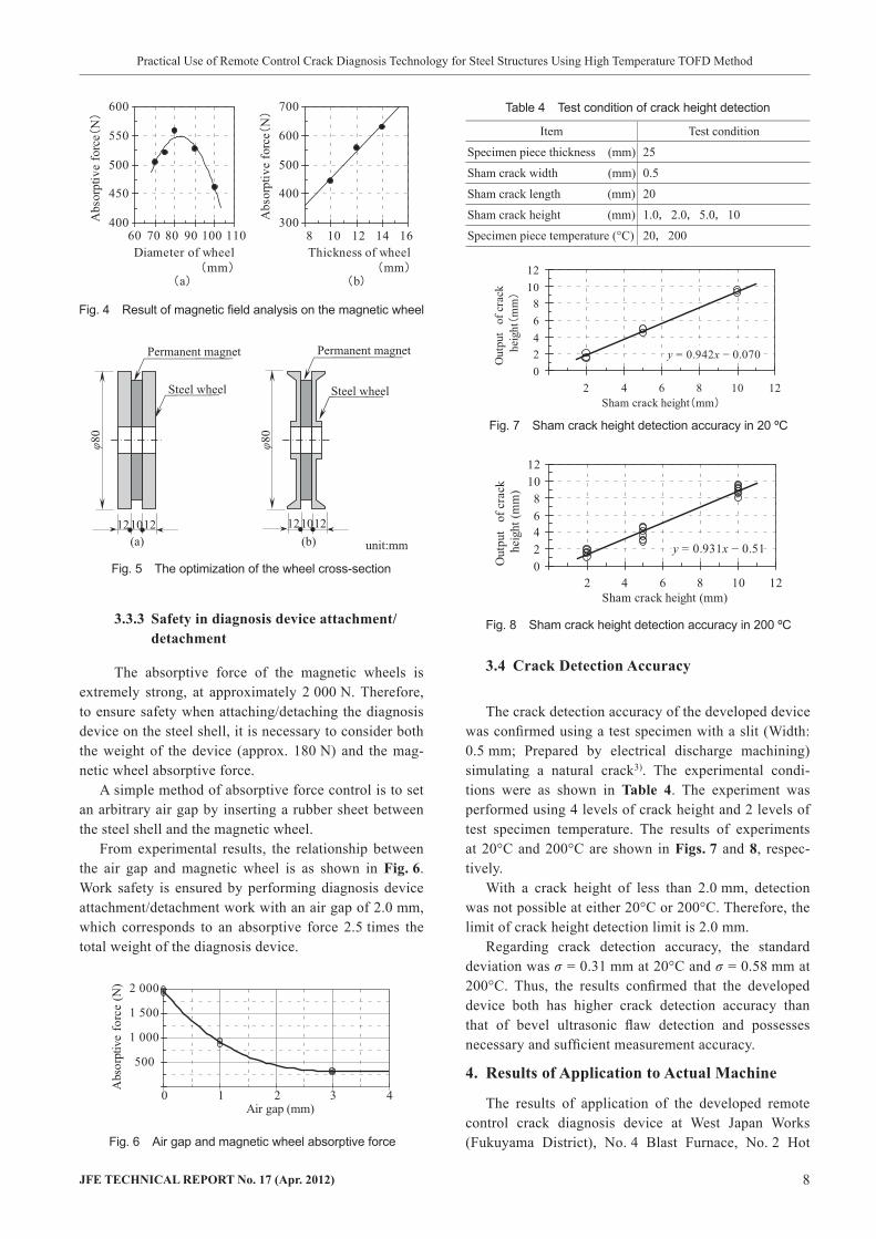
The size of the commercial permanent magnet was limited (Outer diameter: 59 mm in dia., Bore: 19 mm in dia., Thickness: 10 mm). Therefore, a lightweight wheel design with high magnetic absorptive force was obtained by magnetic field analysis. As the strongest absorptive force was obtained with a wheel outer diam-eter of around 80 mm in dia., the outer diameter was set at 80 mm in dia. (Fig. 4(a)).
Absorptive force is proportional to the thickness of the wheel. Therefore, a wheel thickness of 12 mm was adopted, as shown in Fig. 4(b), considering the neces-sary absorptive force and compact design of the device.
Regarding the cross-sectional shape of the wheel, with the proposed lightweight design in Fig. 5(b), weight was 67% and absorptive force was 90% in com-parison with the solid material shown in Fig. 5(a). The design in Fig. 5(b) was adopted considering the excel-lent absorptive force/weight ratio.
Based on the above, a safety factor of 10.7 was secured for prevention of accidental detachment/falling of the device during crack diagnosis of the hot stove shell.
Ditch forcouplingmedium
Supply hole forcoupling medium
Wedge ofangle probe
Fig. 3 Machining ditch for wedge coupling medium
Photo 4 Back of the sensor overview
Item Neodymium Al-Ni-Co Samarium-Cobalt Ferrite
Magnetic force ◎ ○ ○ △Coercivity ◎ △ ○ ○Toughness ◎ ○ △ △Curie point 300°C 860°C 750°C 450°C
Heat-resistant △ ◎ ○ △◎ : Excellent○ : Possible to be used△ : Relatively inferior
Teble 3 Property comparison of the commercial permanent magnet
JFE TECHNICAL REPORT No. 17 (Apr. 2012) 8
Practical Use of Remote Control Crack Diagnosis Technology for Steel Structures Using High Temperature TOFD Method
3.3.3 Safety in diagnosis device attachment/detachment
The absorptive force of the magnetic wheels is extremely strong, at approximately 2 000 N. Therefore, to ensure safety when attaching/detaching the diagnosis device on the steel shell, it is necessary to consider both the weight of the device (approx. 180 N) and the mag-netic wheel absorptive force.
A simple method of absorptive force control is to set an arbitrary air gap by inserting a rubber sheet between the steel shell and the magnetic wheel.
From experimental results, the relationship between the air gap and magnetic wheel is as shown in Fig. 6. Work safety is ensured by performing diagnosis device attachment/detachment work with an air gap of 2.0 mm, which corresponds to an absorptive force 2.5 times the total weight of the diagnosis device.
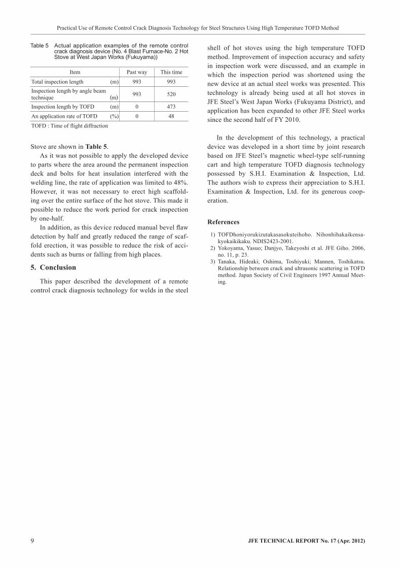
3.4 Crack Detection Accuracy
The crack detection accuracy of the developed device was confirmed using a test specimen with a slit (Width: 0.5 mm; Prepared by electrical discharge machining) simulating a natural crack3). The experimental condi-tions were as shown in Table 4. The experiment was performed using 4 levels of crack height and 2 levels of test specimen temperature. The results of experiments at 20°C and 200°C are shown in Figs. 7 and 8, respec-tively.
With a crack height of less than 2.0 mm, detection was not possible at either 20°C or 200°C. Therefore, the limit of crack height detection limit is 2.0 mm.
Regarding crack detection accuracy, the standard deviation was σ = 0.31 mm at 20°C and σ = 0.58 mm at 200°C. Thus, the results confirmed that the developed device both has higher crack detection accuracy than that of bevel ultrasonic flaw detection and possesses necessary and sufficient measurement accuracy.
4. Results of Application to Actual Machine
The results of application of the developed remote control crack diagnosis device at West Japan Works (Fukuyama District), No. 4 Blast Furnace, No. 2 Hot
400
450
500
550
600
Diameter of wheelmm
Abs
orpt
ive
forc
eN
300
400
500
600
700
Thickness of wheelmm
Abs
orpt
ive
forc
eN
60 70 80 90 100 110 8 10 12 14 16
ba
Fig. 4 Result of magnetic field analysis on the magnetic wheel
Permanent magnet
φ80
φ80
12 1210 12 1210
Steel wheel
Permanent magnet
Steel wheel
(a) (b) unit:mm
Fig. 5 The optimization of the wheel cross-section
500
1 000
1 500
2 000
0 1 2 3 4Air gap (mm)
Abs
orpt
ive
forc
e (N
)
Fig. 6 Air gap and magnetic wheel absorptive force
Item Test condition
Specimen piece thickness (mm) 25
Sham crack width (mm) 0.5
Sham crack length (mm) 20
Sham crack height (mm) 1.0,2.0,5.0,10
Specimen piece temperature (°C) 20,200
Table 4 Test condition of crack height detection
y = 0.942x − 0.07002468
1012
2 4 6 8 10 12Sham crack height mm
Out
put
of c
rack
heig
htm
m
y = 0.931x − 0.5102468
1012
2 4 6 8 10 12Sham crack height (mm)
Out
put
of c
rack
heig
ht (m
m)
Fig. 7 Sham crack height detection accuracy in 20 ºC
Fig. 8 Sham crack height detection accuracy in 200 ºC
9 JFE TECHNICAL REPORT No. 17 (Apr. 2012)
Practical Use of Remote Control Crack Diagnosis Technology for Steel Structures Using High Temperature TOFD Method
Stove are shown in Table 5.As it was not possible to apply the developed device
to parts where the area around the permanent inspection deck and bolts for heat insulation interfered with the welding line, the rate of application was limited to 48%. However, it was not necessary to erect high scaffold-ing over the entire surface of the hot stove. This made it possible to reduce the work period for crack inspection by one-half.
In addition, as this device reduced manual bevel flaw detection by half and greatly reduced the range of scaf-fold erection, it was possible to reduce the risk of acci-dents such as burns or falling from high places.
5. Conclusion
This paper described the development of a remote control crack diagnosis technology for welds in the steel
shell of hot stoves using the high temperature TOFD method. Improvement of inspection accuracy and safety in inspection work were discussed, and an example in which the inspection period was shortened using the new device at an actual steel works was presented. This technology is already being used at all hot stoves in JFE Steel’s West Japan Works (Fukuyama District), and application has been expanded to other JFE Steel works since the second half of FY 2010.
In the development of this technology, a practical device was developed in a short time by joint research based on JFE Steel’s magnetic wheel-type self-running cart and high temperature TOFD diagnosis technology possessed by S.H.I. Examination & Inspection, Ltd. The authors wish to express their appreciation to S.H.I. Examination & Inspection, Ltd. for its generous coop-eration.
References
1) TOFDhoniyorukizutakasasokuteihoho. Nihonhihakaikensa-kyokaikikaku. NDIS2423-2001.
2) Yokoyama, Yasuo; Danjyo, Takeyoshi et al. JFE Giho. 2006, no. 11, p. 23.
3) Tanaka, Hideaki; Oshima, Toshiyuki; Mannen, Toshikatsu. Relationship between crack and ultrasonic scattering in TOFD method. Japan Society of Civil Engineers 1997 Annual Meet-ing.
Item Past way This time
Total inspection length (m) 993 993Inspection length by angle beam technique (m) 993 520
Inspection length by TOFD (m) 0 473
An application rate of TOFD (%) 0 48
TOFD : Time of flight diffraction
Table 5 Actual application examples of the remote control crack diagnosis device (No. 4 Blast Furnace-No. 2 Hot Stove at West Japan Works (Fukuyama))