practical - teatr-obraz.rubiblioteka.teatr-obraz.ru/.../practical_cinematography.pdfnow i have set...
TRANSCRIPT

Practical Cinematography
Prelims 12/16/04 3:23 PM Page i

Dedication
To the memory of my father
Leslie J. Wheelerwho taught me the
Principles of Cinematography
Prelims 12/16/04 3:23 PM Page ii
PracticalCinematographySecond edition
Paul Wheeler BSC FBKS
AMSTERDAM • BOSTON • HEIDELBERG • LONDON • NEW YORK • OXFORD
PARIS • SAN DIEGO • SAN FRANCISCO • SINGAPORE • SYDNEY • TOKYO
Focal Press is an imprint of Elsevier
Prelims 12/16/04 3:23 PM Page iii
Focal PressAn imprint of ElsevierLinacre House, Jordan Hill, Oxford OX2 8DP30 Corporate Drive, Burlington MA 01803
First published 2000Reprinted 2001Second edition 2005
Copyright © 2000, 2005 Paul Wheeler. All rights reserved
The right of Paul Wheeler to be identified as the author of this work hasbeen asserted in accordance with the Copyright, Designs and Patents Act 1988
No part of this publication may be reproduced in any material form (including photocopying or storing in any medium by electronic means and whether or not transiently or incidentally to some other use of thispublication) without the written permission of the copyright holder except in accordance with the provisions of the Copyright, Designs and Patents Act 1988 or under the terms of a licence issued by the Copyright LicensingAgency Ltd, 90 Tottenham Court Road, London, England W1T 4LP.Applications for the copyright holder’s written permission to reproduce any part of this publication should be addressed to the publisher
Permissions may be sought directly from Elsevier’s Science and Technology Rights Department in Oxford, UK: phone: (�44) (0) 1865 843830; fax:(�44) (0) 1865 853333; e-mail: [email protected]. You may alsocomplete your request on-line via the Elsevier homepage (www.elsevier.com),by selecting ‘Customer Support’ and then ‘Obtaining Permissions’
British Library Cataloguing in Publication DataA catalogue record for this book is available from the British Library
Library of Congress Cataloguing in Publication DataA catalogue record for this book is available from the Library of Congress
ISBN 0 240 51962 0
Printed and bound in USA
For information on all Focal Press publications visit ourwebsite at: www.focalpress.com
Prelims 12/16/04 3:23 PM Page iv

Contents
Preface ix
About the author xi
Acknowledgements xiii
Introduction xv
PART ONE People 11 The Director of Photography – an overview 3
The DP’s responsibilities 3
2 The DP’s preparation 7Research 7Preparing for a shoot 8
3 The camera crew 24An overview 24The trainee 24The clapper loader (AC2 or 2nd AC) 25The focus puller (AC1 or 1st AC) 30The camera operator 31The Director of Photography 31The grip or dolly grip 32The gaffer 33Crew protocol 33
PART TWO The Technology 354 The motion picture camera 37
The persistence of vision 37Frame rates 38The intermittent mechanism 39The reflex viewfinder 43Viewing screens 45The film magazine 45Film camera layout 47
v
Prelims 12/16/04 3:23 PM Page v
5 Lenses 49Artistic decisions 49Modern lens designs 57Lens distortion and aberrations 59
6 Film stock 62What is film? 62The history of the negative/positive photographic process 62The basic photographic process 63Colour negative film 69Grain and graininess 71When does grain become unacceptable? 72Perforations 72Edge numbers 74Care, shipping and handling 75
7 Basic sensitometry 77
8 The laboratory 82The laboratory contact 82Printer lights 83Contact printing 84Optical printers 84Negative cutting 86Cinema release prints 87The ‘long-handled’ negative cut 88Film grading 90Telecine grading 90
9 Digital intermediates 92Why turn a photographic image into digits? 92What do we mean by ‘digital’? 93The binary code 93Linear and logarithmic sampling 94Image acquisition 96The 16 mm DI route 97Deliverables 97
PART THREE The Cinematographer’s Craft 9910 Exposure meters 101
Camera speed 101Shutter speed 101Average scene reflectance values 102Types of exposure meter 102
11 Lighting ratios 107Defining a lighting ratio 107Visualizing lighting ratios 107Lighting ratios for film and television 107Lighting ratios when shooting for both cinema and television 109Using lighting ratios on the set 110Controlling the whole scene 110
vi Contents
Prelims 12/16/04 3:23 PM Page vi

12 Three-point image control 111There’s no such thing as exposure latitude 111Three-point image control 112Relating the three points to the sensitometric curve 113Control for television 114
13 Using the 18 per cent grey card 115The messenger 115Controlling print density 116Shifting colour 117Intentional colour changes 117Developments in grey cards 118Conclusions 119
14 Colour temperature 120What is colour temperature? 120Filters and Mired shift values 121The colour temperature meter 123Colour film 124Correcting lamps 126
15 Camera filters 128Colour-compensating filters 128Colour-correction filters 128Skin tone warmer 129Sepia, coral, colour effects, etc. 129Graduated filters 129Neutral density filters 130Low contrast filters 130Ultra contrast filters 130Fog filters 130Double fog filters 131Pro-mist filters 131Star filters 131Nets 131Matching shots 132Enhancing filters 132Fluorescent light correction 132Polar screens 132Filter factors 133The pan glass or viewing glass 133
16 Depth of field 135Depth of focus 135Circles of confusion 135Depth of field and Super 16 to 35 mm blow-ups 137Super 16 mm and 16 � 9 television 138Depth of field of 35 mm film when only shown on television 138Choosing the circle of confusion to use on set 138The effect of aperture on depth of field 139The effect of focal length on depth of field 139The mathematics of depth of field 141Depth of field calculators 142
Contents vii
Prelims 12/16/04 3:23 PM Page vii

17 Testing 146Why so much checking? 146Who checks? 146Tests that involve shooting film 147Lens testing 150Gamma testing 153What to do with the film tests 153Non-film testing 153Stores, supplies and expendables 154The camera car 156
PART FOUR Operating 15718 Composition and the rule of thirds 159
Framing using the rule of thirds 159Framing using the sixths 162Diagonal framing 163Complex and combined composition 163
19 Lenses and perspective 166Frame size and focal length 166Perspective 167Focal length and emotional involvement 171What is a ‘normal’ focal length lens? 176
20 Aspect ratios 177The 35 mm frame 177The aspect ratio 177Widescreen 178Three-perforation pull-down 178Two-perforation pull-down 179Anamorphic 18065 mm and 70 mm 180Super 35 182Television 183
PART FIVE The Future 18721 Aspect ratios when shooting for television 189
The nature of the problem 189History – the evolution of the Super 16 mm format 18916 � 9 television and Super 16 191Framing in several formats 192Framing solutions 194Festival prints 197
22 High Definition – HD 198Is film dead? 198Three-chip cameras 198Single-chip cameras 199Digital presentation 199Conclusions 199
Index 201
viii Contents
Prelims 12/16/04 3:23 PM Page viii
Preface
When I joined the BBC in the 1960s as a trainee projectionist, I was theyoungest trainee at that time. I was lucky enough to be entering a worldwhich offered the best possible training for any aspiring film-maker.AsI progressed through the grades, becoming eventually one of the sixsenior film cameramen before leaving to go freelance, I enjoyed a sub-stantial amount of practical and theoretical training. That training nolonger exists – indeed, the BBC Film Department no longer exists, andyou cannot get that training anywhere now.
One of the most enjoyable aspects of being a Director of Photographyis the opportunity to shoot a wide variety of work. Recently, for instance,I have shot three hours of 35 mm, three hours of Super 16, two hours of Digi Beta, and a one-hour television studio opera and three hours ofHigh Definition – HD. This variety, combined with the opportunity towork with different producers, directors, actors and crew, makes oursone of the most stimulating jobs I know.
Some years ago, I was asked to stand in as Head of Cinematographyat the National Film and Television School. Since then, I haverepeated that enjoyable position. I have also been asked to take vari-ous short courses in a variety of training establishments, something Ialways enjoy doing, if I am not shooting.
Since I wrote the first edition of this book, I have had a great deal offeedback from readers and this has led me to a greater understanding oftheir needs. Therefore, this new edition has a more defined purpose – to lead a student or someone in a lower grade than the DP to gain theknowledge to be able to aspire to that most wonderful of jobs – theDirector of Photography.
This edition, therefore, starts with the definition and description ofthe tasks of the DP and goes on to describe all the necessary technicalknowledge one might need to get a commission as a DP.
As I have always found it easier to explain theoretical principlesusing diagrams and pictures in preference to relying on words alone,this book contains a large number of figures. Indeed, for some of thesections, I prepared the figures first and then wrote the text afterwards.
In this new edition there are some added chapters, a complete reor-ganization of the structure of the book, together with many addedillustrations, including over 20 photographs.
Paul Wheeler
Prelims 12/16/04 3:23 PM Page ix

This page intentionally left blank
About the author
Paul Wheeler has a wealth of practical experience as a cinematog-rapher combined with wide experience as a highly respected trainer.After 25 years with the BBC, by the end of which he was one of onlysix senior film cameramen out of a total of 63 DPs employed there atthat time, he left to go freelance.
In the years since leaving the BBC, Paul has had a flourishing careerwhich has bought him many awards both in the UK and internationally.In between films, he has stood in as Head of Cinematography at theNational Film and Television School a number of times and still takesmaster classes there. He was also Head of Cinematography at theRoyal College of Art. Paul regularly teaches at the New York FilmAcademy in London (www.nyfa.com) as Tutor in Advanced Cinemato-graphy and runs courses at the National Short Course Training Program(www.nftsfilm-tv.ac.uk).
While still maintaining a busy shooting schedule, Paul has decidedto spend more time writing and teaching in an effort to improve thequality of knowledge among young Directors of Photography.
Paul’s other two books, both published by Focal Press, are DigitalCinematography and High Definition and 24P Cinematography.
Prelims 12/16/04 3:23 PM Page xi

This page intentionally left blank

Acknowledgements
Everyone listed here has made significant contributions to the writingof this book. They are listed in no particular order.
Paul Boutle, Brian Newman, Rowland Little, Mike Salter, GarryWillis, Julian Morson, Suzi Jackobson, Renos Louka, Mike McHugh,Alan Piper, Peter Swarbrick, Tony Harcourt, Paddy Seale, RogerCrittenden, Deanne Edwards and Steve Shaw.
All the illustrations are the copyright of the author with the exception of:
Figure 5.5, which is the copyright of Cooke Optics Limited.Figure 17.2, which is the copyright of KJM Consultants.
Prelims 12/16/04 3:23 PM Page xiii

This page intentionally left blank
Introduction
The premise I used to write this, the second edition of this book, is dif-ferent from that I used for the first edition.
Now I have set out my stall in the first chapter, in which I describethe tasks and responsibilities of the Director of Photography. The restof the book then tells you how to gain the skills and knowledge youwill need, one day, to get your first job as a DP.
You may not use some of the knowledge contained herein on a day-to-day basis on the set, but if you have it somewhere at the back ofyour mind you will be a much more proficient DP.
I have also been very conscious of the skills needed in the positionsleading up to the DP’s job; hence, there are chapters on focus pulling,circles of confusion, etc. to enable you to become a very competent 1stAC or focus puller. There are chapters on composition and relatedmatters to take you further on to becoming the camera operator.
Then there is all you will need regarding lighting ratios, exposuremeters and what your crew can do for you, together with chapters onthe laboratory, grading or timing and digital intermediates that willtake you finally to the DP’s position.
Prelims 12/16/04 3:23 PM Page xv

This page intentionally left blank

Part One
People
Chap-01 12/16/04 3:03 PM Page 1

This page intentionally left blank
1
The Director ofPhotography – anoverview
I imagine most people buying this book will have aspirations tobecome a Director of Photography (DP), and therefore I will start the first chapter by discussing and defining the roles and tasksrequired of the DP. The rest of the book will take you through the necessary knowledge you will need to acquire before you can use thetitle DP.
The DP is the senior head of department (HOD), whose level ofresponsibility and depth and breadth of tasks may only be equalled,and then only on a very big picture, by the production designer.All theHODs work to the director.
The prime job of the DP is to create the visual mood of the film andthis is primarily achieved by the use and control of light. This, to mymind, is the most exciting part of the job. Even on a simple exterior,the DP will be making judgements that can materially affect the waythe audience will perceive the message the script, the direction and thecharacters the actors are playing is interpreted.
My firm belief is that to bring the most to a movie and also to get the maximum enjoyment from shooting it, the DP must get the prepar-ation right. Nothing, to me, affects the outcome more significantly, noteven your talent.
The DP’s responsibilities
The DP will be responsible for many things and I am not going to list allof them here. If you would like to peruse a detailed list, the AmericanCinematographer gave a full and exhaustive list in their January 2003edition and that took three pages of small type. Nevertheless, here arethe actions and responsibilities I consider most relevant and mostlikely to occur; use them as a check list if you will.
3
Chap-01 12/16/04 3:03 PM Page 3
In early pre-production● The first and most important matter is to discuss, in depth and pos-
sibly on many occasions, the script with the director until you areboth in complete agreement as to the overall look of the film.
● In order to achieve the above, you will have had to have read thescript several times, often between your meetings with the dir-ector. Early on, you should have made some decisions as to the ebband flow of the emotional content of the script, so that the mood ofyour photography will be sympathetic to the story needs.
● During your discussions with the director, the production designerwill be having similar discussions and it is most important that theDP and the production designer do not go off in different direc-tions. Very early on, you and the production designer will need tokeep in close contact; this will necessitate some meetings with justthe two of you and some with the director present.
● Stay in close contact with the locations department and scout, orrecce, proposed locations as early as possible.
● If sets are to be built, then you will need to keep a close eye on theprogress of the plans, as simple changes that might mean nothingto others can materially affect the ease with which you will be ableto light and shoot the necessary scenes.This primarily relates to thesize of the sets and their positioning within the studio.
● If the director wishes to work with storyboards, you should keep inclose contact during their creation.A good storyboard artist can beone of your greatest allies during pre-production. If the directorprefers not to work with a storyboard artist, perhaps through per-sonal preference or even budgetary restraints, a storyboard fromthe director, even if only drawn as stick men and women, can stillbe a useful tool, especially if the director does not have the mostwonderful ‘picture’ imagination. Do not take this comment as inany way derogatory; if that director has hired the DP for theirvisual imagination knowing it will complement theirs, that DPmight very well enjoy making a more significant contribution tothe movie in question. But remember to let the director make ittheir own. Don’t tell everybody it was your idea; subtlety gets youhired more often.
● Come up with preliminary lighting plots as early as you can so thatyou can give the lighting company an idea of what you will beneeding, and by assessing the number and type of lamps you willneed the production office can get provisional lighting budgetsorganized.
● You will need to nominate your technical crew, as well as chooseyour film laboratory and equipment suppliers.
Close to shoot preparation● Approve with wardrobe department all the colours and textures
they are intending to use.● Check any specific make-up requirements such as prosthetics, etc.● Visit all sets that are still under construction together with the pro-
duction designer and the construction manager.● Visit sets with the production designer when construction is fin-
ished to approve colours and textures.
4 Practical Cinematography
Chap-01 12/16/04 3:03 PM Page 4
● Work with the assistant directors to formulate workable schedulesand remind them of any scenes that are time specific due to sunposition or tides, etc.
● Formulate your film stock breakdowns and your Technical Diary.See Chapter 2 as to how to do this.
● Attend all readings, run-throughs and off-set rehearsals. Thesemay be the first time you get to see your artists in the flesh andyour pre-visualization, from now on, will include the faces you will be photographing rather than your interpretation before theywere cast.
● Establish that your shooting crew has amassed all the equipmentyou have ordered and that they are satisfied that their testing hasbeen successful.
● Make contact with your laboratory, check who will be your dailycontact and who will be grading (timing in the US) your rushes(dailies in the US). Your rushes or dailies are the first print everstruck from the camera negative and can be extraordinarily enlight-ening, especially early on in the shooting of a movie. Establish withyour lab contact the processes you will require and ensure thatthey are fully aware of the look you are going for.
● Shoot and approve any tests you want to carry out, such as emul-sion tests, wardrobe colour tests, make-up and prosthetics tests.
● Finalize lighting plans and communicate them to the gaffer.
During shooting● Get a laboratory report as early as possible.● Watch the rehearsals, or block-outs, of the scene to be shot.● Devise and agree with the Director the shots required for the
upcoming scene.● Agree the most convenient shooting order with both the director
and the first assistant director (1st AD).● Ensure your lighting plan has been carried out to your wishes; con-
firm the stop to the first assistant camera (1st AC or focus puller).● Work with the 1st AD on background action. This may depend on
the union agreements with the background artists; it is common inthe UK that the 1st AD and the DP may direct background artistswithout putting up their daily rate, but if the director gives theminstruction they will earn significantly more for their day’s work.Check the agreement with the production office.
● Give camera set-ups to your camera operator and confirm thesewith the director.
● Set any additional cameras for stunts, etc.● At the end of each scene, confirm with the director that you have
sufficient and appropriate shots to have adequately covered thescene. Advise the director as to additional shots if you think theeditor may need them.
● Make sure that still photography and, if on set, the EPK (ElectronicPress Kit) crew have all the materials they need.This is often over-looked, but to the DP it can be vital that all the pictures generatedon set are as good as the DP’s pictures. Bad publicity photographs,still or moving, can seriously damage a DP’s reputation.
● Last thing at the end of the shooting day, confirm tomorrow’sscenes with the director and the 1st AD.
The director of photography – an overview 5
Chap-01 12/16/04 3:03 PM Page 5

● If the director wishes, discuss tomorrow’s work.● Check and approve call sheets for the following day before they
are made official.● Check if any of the junior members of your crew wish to ask you
questions about the day’s shooting in order to help their careerdevelopment.
Post-production● Time, or grade, any early trailers that may be being constructed.● Check any EPKs to make sure they are of sufficient technical quality.● Approve all effect or composite shots before they become part of
the final cut.● Time, or grade, the final cut.● Attend digital intermediate (DI) grade if this route has been
chosen. For further information on DIs, see Chapter 9.● Approve or modify answer prints as necessary.● Attend all transfers to tape versions.● Supervise pan and scan recompositions.● Supervise and/or approve all other deliverables – VHS, HD, SD,
Pal versions, NTSC versions, etc.● Look for the next picture to shoot.
6 Practical Cinematography
Chap-01 12/16/04 3:03 PM Page 6
2
The DP’s preparation
Research
Many pictures require specific, detailed research, particularly if theyare period pieces, or if the director asks for a certain style or look.Withthe run-up and preparation times currently being scheduled, however,there is often too little time to research your subject properly. It is there-fore useful to accumulate a store of reference material or to have agood idea where such material can be found. This can help not justwith preparing for a shoot, but also with an initial interview for a pic-ture. Discussing a script you only received 24 hours earlier with adirector who has been living with it for months can be a lot easier ifyou have an understanding of the script’s context and can knowledge-ably refer to images that relate to that script.
Regular visits to second-hand bookstores can provide a usefullibrary of old picture books at very little cost. Several years before Ineeded them, I acquired a marvellous set of books covering the yearsof the Second World War almost entirely comprising of photographstaken at the time with minimal captions; there is a book for each year.
Some five or so years later, I was asked to shoot a picture whichopened with men in a train returning from the Dieppe raid of 1942with flashbacks of the men being rescued from the waters along theFrench coast. My set of books provided pictures of men actually in oil-covered water being picked out of a life raft after that raid, a picture ofa woman waiting for a train containing survivors of that raid and oneof people using an underground station as a bomb shelter. All thesescenes were scenes in the script I had been offered and I was able tobase my interpretation of the script on them.
While it is the DP’s job to interpret the script and the director’svision of that script, it is an immense help if you can base your imaginedpictures on reality – it brings a greater believability to the finished film.
Old photographic books are useful (as well as quite fun) to collect, asare books of fashion photographs. With old photographs it is often asuseful to imagine why the picture is shot and styled in a certain way,as this puts one’s thinking into the mind of the original photographerand you can begin to feel more of the mood of the times.
7
Chap-02 12/16/04 3:05 PM Page 7
8 Practical Cinematography
Nowadays, there are even books published on specific times. I have an excellent book, The Golden Years, a celebration of an Edwardiansummer – I haven’t made the film to go with it yet but its time will come.
Art books are a favourite starting point, especially of directors.When we made the BBC film The Dark Angel based on the bookUncle Silas by Sheridan Fenau, the director, during pre-production,showed me many pictures of Victorian paintings as references for vari-ous scenes. Once the shoot started, he preferred not to show me anyphotocopies of reference pictures he had in his script, as he did notwant to inhibit my original thinking at that stage.
While touching on the subject of photocopying, it is important to beaware of the copyright on the original, be it pictures or words. Mostlarge companies have bought a buy-out licence for limited copying,but if either they or you don’t have legal access to the material youmay find yourself in trouble.
The painter I, and I imagine all cinematographers, get asked to emulate most is Vermeer. Not easy, but it can be done. I was onceasked for a Frans Hals look, but persuaded the director against thatbecause the film was destined for television and there would havebeen so much black on the screen the actors might have becomeunrecognizable. Frans Hals’ pictures require contemplation and tele-vision cutting rates give no time for that. Suggesting we shot anothermovie with reference to Edward Hopper was a brave move but I thinkwe pulled it off. One very large lamp to give a single, crisp, shadowacross the set and a light overall fill, together with careful locationfinding, was a good start. I just pray nobody ever asks for a JacksonPollock!
Making up your own scrapbooks is an excellent way to accumulateimages and enables you to add pictures from newspapers and maga-zines to your collection. Keep faces, buildings, events and all the rest in separate scrapbooks to enable easy reference. The very nature ofthese books is random, as pictures will be added in acquisition order,but this offers a definite advantage for, when I am stuck for an imageto work from, just flicking through a couple of scrapbooks will as oftenas not start my mind off down an interesting path – not necessarilyfrom a particular picture, but somehow the randomness fires up ideasand unlocks my visual imagination.
Preparing for a shoot
The recces or scoutingThe recce, the English colloquial abbreviation for reconnoitre, orscouting as Americans call it, comes in two parts. Recceing with thedirector and/or the location manager some time prior to principalphotography is usually productive and enjoyable. The technical recce,which usually occurs just a week or two before the shoot commences,where the DP has to finalize all the technical requirements, is usuallystraightforward hard work.
Recceing with the director and other department heads is a most creative process. It is the time, if you haven’t worked together before, toget to know each other and understand each other’s visualization of the film.At this stage there is often, still, a choice of some of the locations
Chap-02 12/16/04 3:05 PM Page 8

to be used and making the decisions together, helped by the locationmanager, is a valuable investment in the look of the film.
There will be much discussion on a director’s recce as to costs andfacilities needed for the various scenes. One should make the directoraware of scenes that may require out of the ordinary equipment orlabour. It is not uncommon for the director and the DP to discuss thevalue to the story of individual scenes as this relates to their costs, andmake sure they are spending the budget on the important scenesrather than, as can happen, find they are spending huge amounts ofcash to solve problems on scenes that do not necessarily warrant thatinvestment.
Only when you have seen the primary locations can you start to putthe images together in your mind. I often ask for photocopies of theleading actors’ publicity photographs before the recce, so that I canput faces into the rooms and spaces.
I find the technical recce perhaps the hardest and most intense partof the film-making process, for in just a few days I must finalize all thetechnical requirements, agree with my gaffer as to the logistics ofevery location and ensure that all the equipment suppliers, and theproduction office, are aware of the call-off of equipment for the nextseveral weeks.
All the other departments will be bringing you their problems,where they impact on your own, during these few days. Decisionsmade now must be of the highest quality, as a poor judgement now willcome back to haunt you in several weeks’ time.
It is for these reasons that I make the most thorough preparationsand produce the lists discussed below.
The DP’s preparationAs schedules get tighter and budgets decrease, perhaps the most effect-ive way a cinematographer can reclaim lighting time on the set is toinvest time in preparation. Without good preparation, too much timeon set will be spent answering unnecessary questions and trying tosteal time to make arrangements for upcoming shooting days, whichare not, as yet, fully organized. Thus, with good preparation, a DP’stime can be better deployed.
The most effective way of releasing time is to publish, before thefirst day of principal photography, a series of documents that allowanyone connected with the necessary arrangements to quickly, andeasily, refer to the DP’s requirements and make their contributionwithout further reference to the cinematographer.
Two things need to happen for this to be without trauma and to beeffective. Firstly, the cinematographer has to give the time to the pro-ject. Secondly, they have to have a system in place to produce the docu-mentation efficiently.
If you are comfortable using a computer, then things are easier. Onething computers are exceptionally good at is repeat business. Onceyou have generated a list they seem to positively revel in your abilityto make changes to that list and to deliver a new version very quickly.
My greatest ally in this important area of efficiency is a palmtop or laptop computer. I used to use a Psion but these are no longermade, so now I store all my contacts, which at the last count numbered
The DP’s preparation 9
Chap-02 12/16/04 3:05 PM Page 9
nearly 500, in my Palm and do all the lists and data for the shoot on aToshiba laptop, which is powerful enough to be my main computer. Idon’t own a desktop.A modern laptop is all I need these days; indeed,this and my other two books were all written on a series of Toshibas,including the making of all the illustrations. Both my Palm and myToshiba contain all this, together with an enormous database of justabout every technician with whom I have ever worked.
Three words of warning: if you decide to work up your data for apicture on a laptop, make regular backups. I know it seems obviousbut it is essential. Also, make sure the computer is insured; unfortu-nately, it is almost impossible to get insurance on the data containedon the hard drive so, again, it is your responsibility to make thosebackups. The production you are currently working on may be kindenough to cover it, but it is best to have your own insurance for, if not,fate may just decide it is going missing the day after you come off thecompany insurance.
If you do not want to use a computer, the alternative is to use acheck-box list. Here you carefully write out your lists with just abouteverything you could possibly ever need on any production with acheck-box against every entry. For each new production, you photo-copy your original list and then just mark the items you require on thisoccasion.
There are four publications I provide the production with, all serv-ing a different purpose:
1 The camera equipment list2 The lighting equipment list3 The film stock breakdown4 The technical schedule.
In order to discuss the use, importance and preparation of these docu-ments, I will refer to just one film, Neville’s Island, a feature-length filmshot in England for prime-time television transmission. This formatcontains most of the problems associated with any film production. Itis also valuable that all the lists come from the same production for,in many ways, they are interrelated.
The camera equipment listThe camera equipment list will probably be published twice. The lineproducer, or production manager, will usually ask the DP early on inthe production run-up for a guess, or wish list, of the equipment thatwill be required as the basic kit in order to get competitive quotesfrom different suppliers. This does not take away the DP’s right tonominate a preferred supplier.
It is important that this list is reasonable and not an ‘if only I couldhave’ list. At this stage of pre-production, one does not want tofrighten the budget controllers with a foolish amount of equipment. Itis more important to list a reasonable kit in order that comparativeestimates of different suppliers’ prices may be obtained.
Once the supplier has been chosen, the recce is over and a basic listcan be decided upon, it is vital that you provide this new list as soon aspossible.This is not only so that a firm quote can be obtained, but also,more important to the DP, to ensure that the chosen supplier candeliver all their requirements or, if they need to subcontract some
10 Practical Cinematography
Chap-02 12/16/04 3:05 PM Page 10
equipment, they then have sufficient time to make the necessaryarrangements.
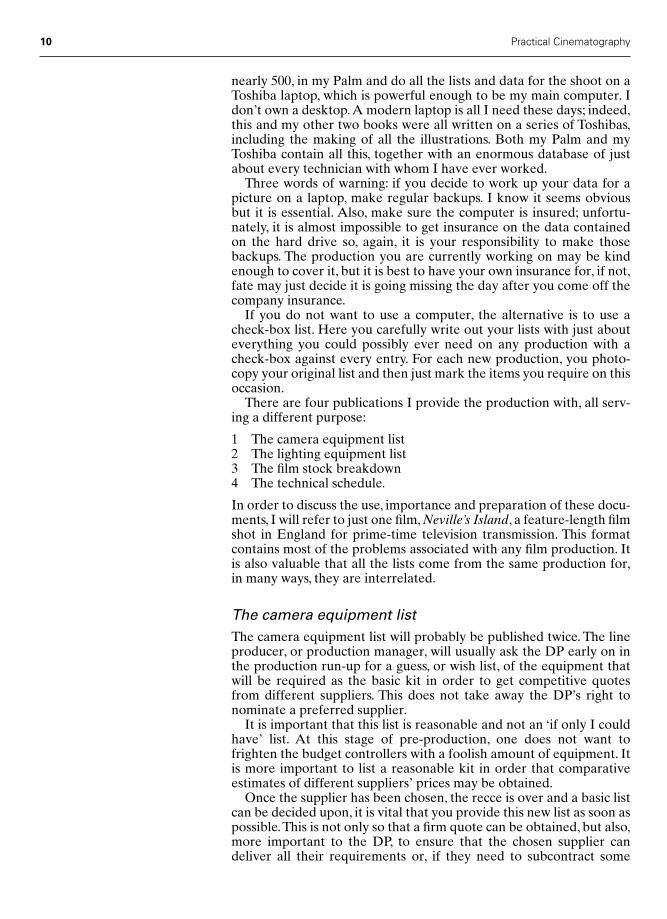
Figure 2.1 shows copies of the camera equipment list as delivered tothe production office of Neville’s Island just after the technical recce.Not only is all the equipment very accurately detailed, but theassumed supplier is noted as these may differ for various parts of thekit. Each section is quite clearly marked and short-term hire, such asthe second camera body for the time spent away from London, isclearly indicated.
This accuracy is important, as it is quite possible that someone in theproduction office may have to book the equipment while all theinformed staff are out of the office. It is only fair to them that you haveproduced a list that can be read down a phone by someone who knowslittle about camera equipment.This is not only a kindness to them, butan insurance policy for the DP.
In addition, the page number and the full number of pages areclearly shown in the bottom right-hand corner of the page, and in thetop right-hand corner the publication date is shown – this is veryimportant. The DP will quite likely deliver a number of updated ver-sions of the camera equipment list as the production nears the first dayof principal photography. It is very important that anyone on the pro-duction who needs to refer to the list can easily see which is the latestversion.
The camera equipment list, as illustrated, is exactly as written in mycomputer. These days computers are pretty compatible, so you shouldbe able to plug into any office printer if you don’t want the bother ofcarrying a small, portable, one. The DP can return from a recce and,say over lunch, print out various lists, etc. in order to have them readyfor an after-lunch production meeting. This kind of organization isvery much appreciated by the production.
The lighting equipment listAs with the camera list, in all probability the production office willneed an early lighting equipment list in order to obtain comparativecostings from differing suppliers. Unlike the camera list, where a closeguess of the requirements can be made from reading the script, withthe lighting list it is very difficult to give a reasonably accurate judge-ment of one’s needs before having seen all the locations; nevertheless,a list to base budgets upon will be requested.
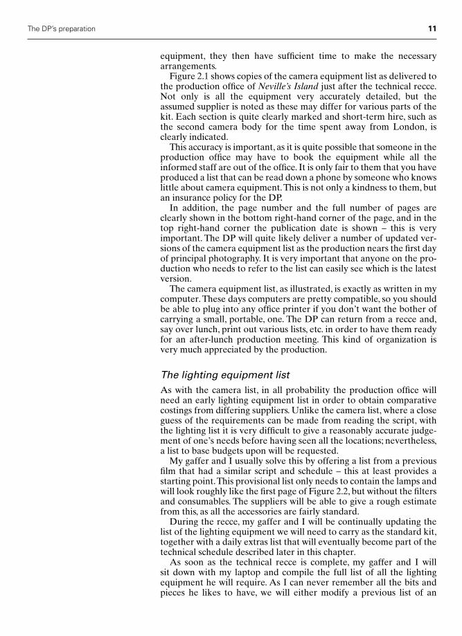
My gaffer and I usually solve this by offering a list from a previousfilm that had a similar script and schedule – this at least provides astarting point.This provisional list only needs to contain the lamps andwill look roughly like the first page of Figure 2.2, but without the filtersand consumables. The suppliers will be able to give a rough estimatefrom this, as all the accessories are fairly standard.
During the recce, my gaffer and I will be continually updating thelist of the lighting equipment we will need to carry as the standard kit,together with a daily extras list that will eventually become part of thetechnical schedule described later in this chapter.
As soon as the technical recce is complete, my gaffer and I will sit down with my laptop and compile the full list of all the lightingequipment he will require. As I can never remember all the bits andpieces he likes to have, we will either modify a previous list of an
The DP’s preparation 11
Chap-02 12/16/04 3:05 PM Page 11

12 Practical Cinematography
Camera Equipment “NEVILLE’S ISLAND” @ 7th October
Aaton XTRprod Camera Kit
Camera Supplier – Cine EuropeAaton XTRprod with video assist � 4 magazines all for super 16 andwith PL lens mount Extension viewfinder with leveler ring2nd Aaton XTRprod with video assist – body only withextension viewfinder and leveler ring from 3th Oct. to 27th Oct only
Zoom Lenses Supplier – Cine EuropeCanon 7–63 mm T2.6 Zoom lens in PL mountCanon 11.5–138 mm T2.5 Zoom lens in PL mount
Prime Lenses Supplier – Cine EuropeAll in Arri PL mount8 mm Optex lens T1.912 mm Zeiss T1.3 High Speed Distagon16 mm Zeiss T1.3 High Speed Distagon25 mm Zeiss T1.3 High Speed Distagon
Telephoto Prime Lenses Supplier – P. W.180 mm Zeiss Sonnar T2.8 (Universal Mount)300 mm Kinoptic T4 (Universal Mount)500 mm Kinoptic T5.7 (Universal Mount)Universal – PL mount adapter
Camera Accessories Supplier – Cine Europe2 � sliding base plates with 19 mm barsArri MB 16 4” production matte box with 4 � 4” filter slides �1 � 4 � 6” filter slideClip on 4” Matte box for DistagonsArri follow focus unit (manual)Arri Lens control system (or Microforce as per David Hedges)
Video Assist Accessories Supplier – Cine Europe9” mains battery monitor4” battery monitorTrolley3 � long & 3 � short BNC cables2 � cable drums4 � Heavy duty batteries
Filters Supplier – P. W.Standard Kit Includes:4 inch Filters: 85, 85C, 0.9 ND. 2 � 85 ND6, Tiffen 812, Promist 1/4, 1/2, 1, 2, 3,UltraCon 1, 2, 3, 4. 2 � Polar, Optical Flat. 0.6 & 0.9 ND Grads. No 1 Sepia3 � 4” Filters: 0.3, 0.6, 0.9 ND Grads, 85B, 85C, 85BN6, 81EF, Tiffen 812.
Paul Wheeler Page 1 of 2
Figure 2.1 Camera equipment list for Neville’s Island
Chap-02 12/16/04 3:05 PM Page 12

The DP’s preparation 13
Camera Equipment “NEVILLE’S ISLAND” @ 7th October
3 inch Filters: 85B, 85C, 85, 85BN6, 81EF, FLB, 82C, 82B, Coral 6, 8, 10, ND6, ND9,LC1, LC2, 4 Point Star, Nos. 1 & 2 Diopters, Split Field Diopter.Series 9 Filters: Plus 1 Diopter, 85B. Nets: Black Dior 10 Denier, Brown Silk, White etc.Cokin Pro: Sunset 1 & 2, Grads: B1, B2, G1, G2. Tobacco grad, 6” Armored glass
Selection of gelatin filters to be charged @ cost of each as used
Grip Equipment Supplier – Cine Europe or GripSuper peewee DollyDoorway dolly150 mm Arri Bowl “world cup”3 way & 4 way Moy levelersPaddle mountOff set arm50� straight railLadderpodLow rockerBazookaAll usual grips “Toys”3 � 8� � 4� boards and frames2 � 4� � 4� boards and frames
Heads & Legs Supplier – P. W.Mitchell lightweight geared head – Moy fittingMitchell front boxEyepiece levelerHeavy duty carbon fibre tall legs – Moy fittingHeavy duty carbon fibre short legs – Moy fitting“Banjo” spreaderRonford Fluid 7 head – with Moy & Arri bowl basesRonford Fluid 15 head – Arri bowl fittingRonford medium duty tall legs – Arri bowl fittingRonford medium duty short legs – Arri bowl fittingRonford dedicated spreaderMoy fitting to Arri bowl adapterShoulder Holder PRO hand held kitVinten Monopod
Waders for entire camera crew Purchase ??
Please Note: Extra equipment needed on a daily basis is shown on the Technical Schedule
Paul Wheeler Page 2 of 2
Figure 2.1 continued
Chap-02 12/16/04 3:05 PM Page 13

14 Practical Cinematography
Lighting List “NEVILLE’S ISLAND” @ 7th October
HMI
2 � 4 k MSR’s2 � 2.5 MSR’s2 � 1.2 ArriSun’s4 � 575 HMI’s2 � 200 MSR Battery Lights � Mains units2 � Sungun battery lights8 � Standard batteries � 1 � heavy duty battery1 � Medium Daylight Bank Chimera for 1.2 ArriSun’s with louvres
FLUORESCENT
2 � 4 bank Kino Flo’s
TUNGSTEN
2 � 2 k Fresnel2 � 2 k Blondes4 � 800 w Redheads4 � l k Pups2 � Lee Zaps8 � Mizars or Kittens4 � Dedo lights1 � Small Quartz Bank Chimera for Redheads1 � Medium Quartz Bank Chimera for 2 k Blondes 3 � Atlas fittings – on TV spigots
PRACTICALS
Selection of tungsten household bulbs, clear & pearl4 � No 1 Photofloods4 � No 2 Photofloods1 � Box 13 amp plugs
FILTERS & CONSUMABLES
1/4, 1/2 & Full Blue1/4, 1/2 & Full CTO0.3, 0.6 & 0.9 ND gelCosmetic Pink, Defusion Fl, F2 & F3, 3002 Rosco soft frost & Spun Glass etc.Rosco Gold & Silver “Soft” reflectorRosco silver/black scrimBlackwrap
Paul Wheeler Page 1 of 3
Figure 2.2 Lighting equipment list for Neville’s Island
Chap-02 12/16/04 3:05 PM Page 14

The DP’s preparation 15
Lighting List “NEVILLE’S ISLAND” @ 7th October
STANDS
10 � Triple Lift12 � Redhead/Blonde stands10 � Flag stands � arms2 � Low boy3 � Double wind up2 � High Rollers2 � Double stand extensions
CABLES
125 amp extension – 500 feet63 amp extension – 600 feet32 amp extension – 10 � 100 feet � 10 � 50 feet � 5 � 25 feet16 amp extension – 10 � 100 feet � 10 � 50 feet � 10 � 25 feet
MAINS DISTRIBUTION
2 � 125 Dist. box2 � 63 Dist. box4 � 32 Dist. box
JUMPERS & SPLITTERS
2 � 63a O/E2 � 125 � 632 � 63 � 3212 � 32 � 1612 � 16 � 1610 � 13 amp to 16 amp jumpers6 � 32 amp open ends6 � 4 way 13 amp6 � 2 way or 1 way 13 amp10 � 13 amp � 16 amp jumpers8 � 16 amp male – chock block
Paul Wheeler Page 2 of 3
Figure 2.2 continued
Chap-02 12/16/04 3:05 PM Page 15

16 Practical Cinematography
Lighting List “NEVILLE’S ISLAND” @ 7th October
ACCESSORIES
2 � Long polecats2 � Medium polecats3 � Short polecats2 � Doorway polecats2 � Trombones4 � Flat plate turtles6 � Spigot reducers10 � Magic arms6 � “C” clamps6 � “G” clamps – large4 � Sash clamps4 � Arri special clamps2 � Pallet knivesSelection of 1/2 & 1 stop netsGood selection of flags & charlie bars2 � Large ulcers2 � 4 � 4 foot reflector, hard & soft6 � Mizar snoots & base plates10 � sand bags1 � Large ladder1 � Zarge1 � Medium stepsPaul’s box of mirrorsPaul’s “Mirror Box” for police lamps1 � 10 foot scaf pole2 � Big Ben6 � Double barrel clamp1 � Bag plastic zip ties8 � Poly holders4 � Frame holders2 � 4 � 4’ foot frames12 � Safety chains4 � 2 k In line dimmers2 � Hanks of sash2 � Rolls gaffer tape100 � Crock clips8 � Head covers1 � Practical box – to contain 10 13 Amp plugs1 � 12 � l2 foot Butterfly � Griflon & Silk � black net � white net1 � 6 � 6 foot Butterfly � Griflon & Silk � black net & white net6 � 8 � 4 Sheet of Black and White polly board
Paul Wheeler Page 3 of 3
Figure 2.2 continued
Chap-02 12/16/04 3:05 PM Page 16
earlier production, or if the list required is radically different, he willsimply dictate the new list to me and I will type it into the computer.This results in a list as shown in Figure 2.2, which shows the actual listused on my example film Neville’s Island.
We then either fax this to the production office or deliver it the fol-lowing morning.A copy is usually also sent directly to the lighting sup-plier. Some urgency is required at this time, as one is usually only a fewdays away from principal photography by the time the last locationhas been recced; final budgets need to be agreed and the supplierneeds to make sure that all the equipment on the list will be ready andon the lighting truck.
Requirements for the generator and lighting equipment truck donot go on the lighting list. My gaffer makes these arrangementsdirectly with the lighting company. The same applies to cherry pickersand towers; these will appear on the technical schedule together withany equipment required on a daily basis.
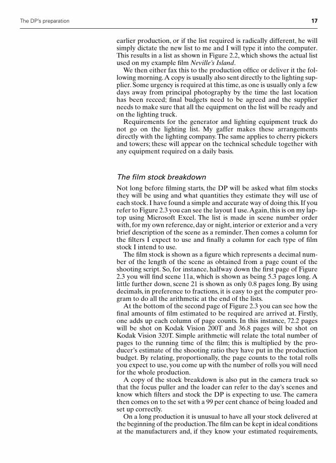
The film stock breakdownNot long before filming starts, the DP will be asked what film stocksthey will be using and what quantities they estimate they will use ofeach stock. I have found a simple and accurate way of doing this. If yourefer to Figure 2.3 you can see the layout I use.Again, this is on my lap-top using Microsoft Excel. The list is made in scene number orderwith, for my own reference, day or night, interior or exterior and a verybrief description of the scene as a reminder. Then comes a column forthe filters I expect to use and finally a column for each type of filmstock I intend to use.
The film stock is shown as a figure which represents a decimal num-ber of the length of the scene as obtained from a page count of theshooting script. So, for instance, halfway down the first page of Figure2.3 you will find scene 11a, which is shown as being 5.3 pages long. Alittle further down, scene 21 is shown as only 0.8 pages long. By usingdecimals, in preference to fractions, it is easy to get the computer pro-gram to do all the arithmetic at the end of the lists.
At the bottom of the second page of Figure 2.3 you can see how thefinal amounts of film estimated to be required are arrived at. Firstly,one adds up each column of page counts. In this instance, 72.2 pageswill be shot on Kodak Vision 200T and 36.8 pages will be shot onKodak Vision 320T. Simple arithmetic will relate the total number ofpages to the running time of the film; this is multiplied by the pro-ducer’s estimate of the shooting ratio they have put in the productionbudget. By relating, proportionally, the page counts to the total rollsyou expect to use, you come up with the number of rolls you will needfor the whole production.
A copy of the stock breakdown is also put in the camera truck sothat the focus puller and the loader can refer to the day’s scenes andknow which filters and stock the DP is expecting to use. The camerathen comes on to the set with a 99 per cent chance of being loaded andset up correctly.
On a long production it is unusual to have all your stock delivered atthe beginning of the production.The film can be kept in ideal conditionsat the manufacturers and, if they know your estimated requirements,
The DP’s preparation 17
Chap-02 12/16/04 3:05 PM Page 17

18 Practical Cinematography
Film Stock Breakdown “NEVILLE’S ISLAND” @ 7th October
Scene Day Int Description Filter Stock StockNight Ext 200 T 320 T
1 D Int Office 85B 1.42 D Ext Valley Road Sepia 0.23 D Int Neville’s Car Sepia 0.34 D Ext Valley Road Sepia 0.25 D Int Angus’s Car Sepia 0.46 D Ext Another Mondeo Sepia 0.27 D Int Roy’s Mondeo Sepia 0.4
7a D Ext Valley Road Sepia 0.48 D I/E Gordon’s Mondeo Sepia 0.6
8a D Ext Neville’s Island Sepia 0.39 D Int Breakfast @ hotel 85B 0.7
10 D Ext Hotel Grounds 85B 0.911 D Ext Gordon’s Beach 85C 1.5
11a D Ext Shingle Beach 85C 5.312 D Ext Shrub Hill 85C 0.513 D Ext Shrub Hill 85C 0.314 D Ext Shrub Hill 85C 1.215 D Ext Shingle Beach 85C 0.516 D Ext Garlic Patch 85C 5.817 D Ext Lookout Tree 85C 0.918 D Ext Heart of the Island 85C 0.519 D Ext Mud Beach 85C 1.620 D Ext Shingle Beach 85C 3.421 D Ext Lookout Tree 85C 0.822 D Ext Shingle Beach 85C 9
END OF PART ONE
23 D Ext Shingle Beach 85C 524 D Ext Shingle Beach 85C 6.325 D Ext Shingle Beach 85C 0.3
25a N Ext Lookout Tree/Cold Moon? None 0.2OR if “ON THE BLINK” SUNSET
26 N EXT Sleeping Patch None 6.327 D INT Boardroom None 1.328 N EXT Sleeping Patch None 0.6
28a N EXT Disco Boat Beach None 1.129 N EXT Heart of Island None 0.330 N EXT Interior Island None 1.6
END OF PART TWO
Paul Wheeler Page 1 of 2
Figure 2.3 Film stock breakdown for Neville’s Island
Chap-02 12/16/04 3:05 PM Page 18

The DP’s preparation 19
Film Stock Breakdown “NEVILLE’S ISLAND” @ 7th October
Scene Day Int Description Filter Stock StockNight Ext 200 T 320 T
31 N EXT Gorse Patch None 1.632 N EXT Bracken None 4.332a D EXT Shingle Beach None 433 D EXT Gordon’s Beach/Shingle Beach None 134 D EXT Shingle Beach None 1.635 D EXT Gordon’s Beach None 0.336 D EXT Shingle Beach None 1.237 D EXT Gordon’s Beach None 0.738 D EXT Lookout Tree None 239 D EXT Shingle Beach None 139a D EXT Shingle Beach None 10NO 40NO 4142 N EXT Promontory None 0.742a N EXT Shingle Beach None 3NO 4344 N EXT Heart of Island (Roy’s Tree) None 4.345 N EXT Shingle Beach None 3.446 N EXT Heart of Island (Roy’s Tree) None 0.447 N EXT HELICOPTER BEACH None 448 EXT Traveling Police Boat None 2.549 N EXT Jetty, Lake None 1.550 N EXT Empty Jetty None 1.2
PAGE COUNT 72.2 36.8
TOTAL PAGES 109 Pages
90 Min Programme @ 12:1 ratio 108 Rolls
OVERALL STOCK REQUIREMENTS
Kodak code 200 T 320 T
TOTAL Stock Required 73 36
First order priorto going to Lake District 40 20
Paul Wheeler Page 2 of 2
Figure 2.3 continued
Chap-02 12/16/04 3:05 PM Page 19

20 Practical Cinematography
Technical Schedule “NEVILLE’S ISLAND” @ 7th October
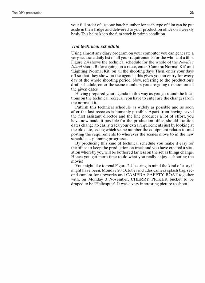
October 1997Mon 13 TRAVEL to Lake District
Cine Jib to travelTue 14 LAKE DISTRICT – Scenes: 2, 4, 6, 7a, 8, 3, 5, 7, 8a
Camera: Normal Kit � Scene 8a CINE JIBLighting: Normal Kit � 3 men
Wed 15 LAKE DISTRICT – Scenes: 16, 17Camera: Normal Kit � LADDERPOD waders as aboveLighting: Normal Kit � 3 men
Thu 16 LAKE DISTRICT – Scenes: 19, 11aCamera: Normal kit � 1 � SPLASH BAG � 6 dry suits (in right sizes) � 6 Pairs Waders (in right sizes)NB Cine Jib returnsLighting: Normal Kit � 3 men
Fri 17 LAKE DISTRICT – Scenes: 38, move to 23Camera: Normal Kit � Ladderpod � wadersLighting: Normal Kit � 3 men
Sat 18 LAKE DISTRICT – Scenes: 24, 25Camera: Normal Kit � Dry suits � wadersLighting: Normal Kit � 3 men
Sun 19 LAKE DISTRICT – Scenes: 20, 22ptCamera: Normal KitLighting: Normal Kit � 3 men
Mon 20 LAKE DISTRICT – Scenes: 33pt, 35, 37, 11 unit move 42, 44pt, 44pt, 45ptCamera Kit: Normal kit � SPLASH BAG � Dry suits � waders2nd Camera for fireworksCAMERA SAFETY BOATLighting: Normal Kit � 3 men
Tue 21 LAKE DISTRICT – Scenes: 20pt, 24pt, 21, 25a (at SUNSET if poss)Camera: Normal kit � LadderpodLighting: Normal Kit � 3 men � shutter box dimmerHEADLIGHT TORCHES
Wed 22 LAKE DISTRICT – Scenes: 10, 49, 50Camera: Normal Kit � second grip travels for Scenes 28a & 49Boomslang OR Giraffe CRANELighting: Normal Kit � 3 men � 8 Atlas fittings � 6 Blondes � 70 feetof festoons with 20 each red, yellow & blue 40 w bulbs � 2 extra menSCAFFOLD TOWER FOR LIGHTING RIG
Paul Wheeler Page 1 of 3
Figure 2.4 Technical schedule for Neville’s Island
Chap-02 12/16/04 3:05 PM Page 20

The DP’s preparation 21
Technical Schedule “NEVILLE’S ISLAND” @ 7th October
Thu 23 LAKE DISTRICT – Storrs Hall Hotel – Scenes: 9,8a (Disco Boat), 28pt, 48Camera: Normal Kit � 2nd cameraCRANE ON JETTY ??? Check Weight LoadingCrane returns tonight ???Lighting: Normal Kit � 3 men � Festoons & battery light forDisco Boat(�Disco lights from DESIGN)SCAFFOLD TOWER FOR LIGHTING RIG
PLEASE CHECK – if we don’t see back to hotel then we can lose extra electricians & lights –if we do I still need them
Fri 24 TRAVEL DAY – Return LondonSat 25 DAY OFFSun 26 DAY OFFMon 27 TRENT PARK – Scenes 22pt, 32a
Camera: Normal KitLighting: Normal Kit � 3 men � stove effect
Tue 28 TRENT PARK – Scenes: 12, 13, 14, 15, 18Camera: Normal KitLighting: Normal Kit � 3 men
Wed 29 TRENT PARK – Scenes: 26, 28Camera: Normal KitLighting: Normal Kit � 3 menSMOKE IN TREES – from design
Thu 30 TRENT PARK – Scenes: 29, 30, 31, 32Camera: Normal KitLighting: Normal Kit � 3 men � 2 EXTRA men � 2 � 12 K HMI’s �2 � Gladiator stands � 4 � 1.2 ArrisunsHEADLIGHT TORCHESSMOKE IN TREES – from design
Fri 31 TRENT PARK – Scenes: 12, 13, 14, 44ptCamera: Normal Kit – LADDER POD � 2nd Camerafor Scene 44Lighting: Normal Kit � 3 men � 2 EXTRA men � 2 � 12 K HMI’s �2 Gladiator stands � 4 � 1.2 ArrisunsHEADLIGHT TORCHESSMOKE IN TREES – from design
Paul Wheeler Page 2 of 3
Figure 2.4 continued
Chap-02 12/16/04 3:05 PM Page 21

22 Practical Cinematography
Technical Schedule “NEVILLE’S ISLAND” @ 7th October
November 1997Sat 1 TRENT PARK – Scenes: 44pt, 46
Camera: Normal Kit � 2nd Camera for fireworksLighting: Normal Kit � 3 men � 2 EXTRA men � 2 � 12 K HMI’s �2 � Gladiator stands � 4 � 1.2 Arrisuns � Shutter boxHEADLIGHT TORCHESSMOKE IN TREES – from design
Sun 2 DAY OFFMon 3 HAWLEY LAKE – Scenes: 47pt, 47pt
Camera: Normal KitLighting: Normal Kit � 3 men � CID Follow spot �HMI battery lamp for boatCHERRY PICKER bucket black draped to be “Helicopter”
Tue 4 HAWLEY LAKE – Scenes: 33pt, 34, 36, 42aCamera: Normal Kit � HEADLIGHT TORCHESLighting: Normal � 3 men
Wed 5 HAWLEY LAKE – Scenes: 47pt, 47pt (Loc. TBC)Camera: Normal KitLighting: Normal Kit � 3 men
Thu 6 HAWLEY LAKE – Scenes: 39pt, 39a ptCamera: Normal KitLighting: Normal Kit � 3 men
Fri 7 HAWLEY LAKE – Scenes: 39aCamera: Normal KitLighting: Normal Kit � 3 men
Sat 8 PRIMETIME Boardroom Scenes 1 & 27Camera: Normal Kit � Black Artcard (from art Dep.) � Multi imagerotating prismLighting: Normal Kit � 3 men � 4 � 200 w MSR’s � Star Burst projector � 1 K Profile follow spot � Cracked oil machineEND OF FILMING!!!
Sun 9 DAY OFF
Mon 10 RETURN GEAR & WRAP – not scheduled by production
Paul Wheeler Page 3 of 3
Figure 2.4 continued
Chap-02 12/16/04 3:05 PM Page 22
your full order of just one batch number for each type of film can be putaside in their fridge and delivered to your production office on a weeklybasis.This helps keep the film stock in prime condition.
The technical scheduleUsing almost any diary program on your computer you can generate avery accurate daily list of all your requirements for the whole of a film.Figure 2.4 shows the technical schedule for the whole of the Neville’sIsland shoot. Before going on a recce, enter ‘Camera: Normal Kit’ and‘Lighting: Normal Kit’ on all the shooting days. Then, enter your daysoff so that they show on the agenda; this gives you an entry for everyday of the whole shooting period. Now, referring to the production’sdraft schedule, enter the scene numbers you are going to shoot on allthe given dates.
Having prepared your agenda in this way as you go round the loca-tions on the technical recce, all you have to enter are the changes fromthe normal kit.
Publish this technical schedule as widely as possible and as soonafter the last recce as is humanly possible. Apart from having savedthe first assistant director and the line producer a lot of effort, youhave now made it possible for the production office, should locationdates change, to easily track your extra requirements just by looking atthe old date, seeing which scene number the equipment relates to, andposting the requirements to wherever the scenes move to in the newschedule as planning progresses.
By producing this kind of technical schedule you make it easy forthe office to keep the production on track and you have created a situ-ation whereby you will be bothered far less on the set as things change.Hence you get more time to do what you really enjoy – shooting themovie!
You might like to read Figure 2.4 bearing in mind the kind of story itmight have been. Monday 20 October includes camera splash bag, sec-ond camera for fireworks and CAMERA SAFETY BOAT togetherwith, on Monday 3 November, CHERRY PICKER bucket to bedraped to be ‘Helicopter’. It was a very interesting picture to shoot!
The DP’s preparation 23
Chap-02 12/16/04 3:05 PM Page 23
3
The camera crew
An overview
Before a camera crew is formed for any production, the DP will prob-ably have had an interview with the director and the producer.Particularly in television, it is quite normal for them to interview per-haps three DPs before making their choice, even if there was a clearfavourite right at the beginning. It is a fortunate DP who is well knownenough to the director and producer to be asked to shoot their filmwithout having to be interviewed.
Once the DP is confirmed they will start to look for their operator.Most DPs have a preferred operator with a second choice in mind in case the first is already booked on another production. It is quiteacceptable for the director to have a significant input into the choiceof operator as, in the UK at least, the director will often work veryclosely with the operator to choose and set up the shots. In America it is equally common for the operator to work solely with the DP. TheDP will, if this is the director’s preferred way of working, most prob-ably have had several meetings with the director and design depart-ment to set the overall look of the film, and as the director and DPoften travel together on an away job there is plenty of time for themto discuss finer points before they reach the set. If they are not travel-ling together it is usual to have a discussion about the next day at theend of the day’s shooting or, if the director doesn’t want to committhemselves, first thing in the morning, perhaps at breakfast.
Once the operator has been chosen they will be asked to nominatea focus puller and clapper loader. These appointments will alwaysrequire the approval of the DP, the producer and probably the director.
The camera crew works in a very supportive way – that is, eachgrade is only as good as the support they receive from the colleaguearound them. The individual crew responsibilities from the traineethrough to the DP are therefore as follows.
The trainee
Many years ago it was common to have a trainee on the crew.Restrictions to budget and the collapse of both the studio system
24
Chap-03 12/16/04 3:05 PM Page 24
The camera crew 25
and large television stations then caused producers to be very reluc-tant to sanction the very small costs of having a trainee. Things havenow improved for trainees for the curious reason that most directorsnow wish to work with video assist, and that facility comes with bat-teries, cables, monitor stands, etc. Providing the director does not wantto record the video image, in which case a trained video technician isthe answer, most producers now see the trainee as an economical wayof having the video assist organized and kept running.
This is all very good news. I am currently working with two clapperloaders who started on my crews as trainees looking after the videoassist. At least one end of the cable is attached to the camera and thatensures that a good and willing trainee will get much advice from theshooting crew. Keeping the shooting crew fed with tea, coffee andsnacks is a marvellous way of ensuring they hire you next time. One ofmy loaders, when my trainee, somehow found time to run an espressocoffee machine two or three times a day. Adding the director to thecamera crew as people he was happy to provide this service to hasensured a very successful transition to the next grade.
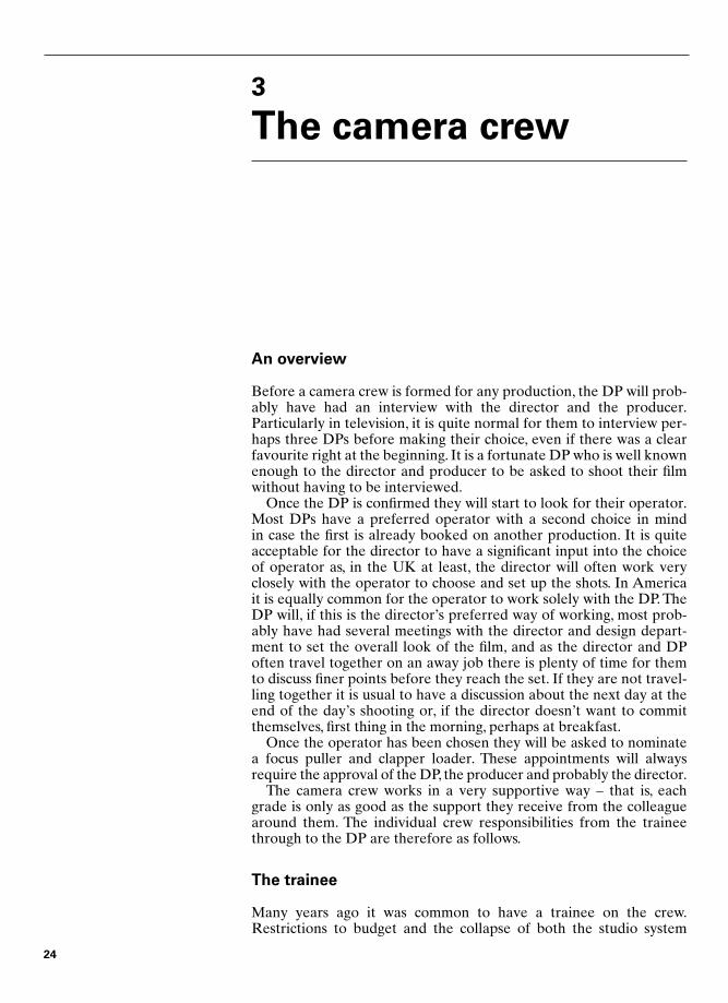
Recently, some clever person invented a marvellous device to helpthe trainee or clapper loader with the tea transportation problem – the‘cup bat’. Figure 3.1 shows this wonderful invention. It is made fromhalf-inch-thick MDF or plywood.The unit carpenter, if talked to nicely,will usually happily make you one in a free moment.The holes are justthe right size for a polystyrene cup to sit in and still sit about an inchproud of the surface. Kept in the set box if the trainee is busy, any mem-ber of the crew can grab it in a spare moment and get the camera crewa cup of tea. If we are shooting exteriors where I, as DP, am not alwaysthat busy, I am quite happy to grab the cup bat and do a tea run.The bathas nine holes: I can use one cup for sugar and a spoon and, having kepta cup for myself, endear myself to seven others on the shooting crew.Including the director and continuity in a tea run is a welcome gesturefrom the camera department.
The clapper loader (AC2 or 2nd AC)
From the focus puller’s point of view, the most important part of theloader’s job is to bring them just about every part of the camera they
Figure 3.1 The cup bat
Chap-03 12/16/04 3:05 PM Page 25
may need during the shooting day. The focus puller must never leavethe camera, so the loader could be thought of as the legs of the focuspuller. A good loader will have the camera car, or truck (in the UKeven a seven-ton truck will usually be referred to as the camera car)very neatly organized with everything in its place and always in thesame place so that it can be found quickly, even in the dark.
A good loader will learn to anticipate which pieces of equipmentwill be needed and when they will be needed; they will then be able tobe standing by with all the parts needed before they are asked.Magazines will be adjacent as and when the camera is close to needingreloading and will be loaded with an appropriate film stock. All thismust be done without cluttering the set; it is not an acceptable solutionto have everything that might be needed very close to the camera.Toomany people will get cross at continually tripping over the cameraboxes and if you are working outdoors then the slightest amount ofrain will cause dreadful panic as equipment is put away. Good antici-pation is essential to being a successful loader.
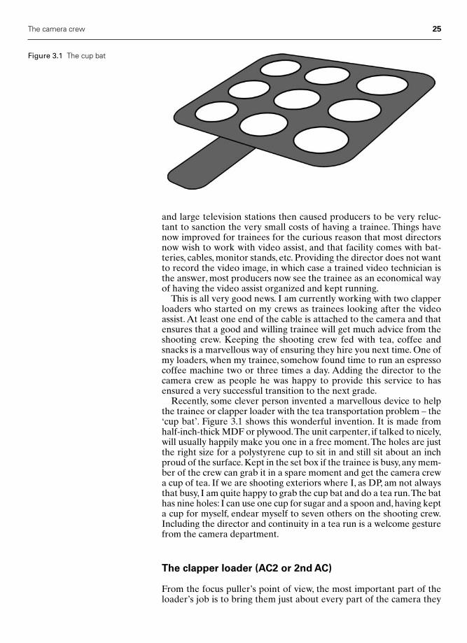
These days, it is the loader’s job to put marks on the floor, usuallywith different coloured camera tape, for both the artists’ sake and thefocus puller’s, these marks not necessarily being for the same purpose.It is a good idea to dedicate a colour to each artist. A very usefulgadget is a ‘tape stick’, as shown in Figure 3.2, this being a hexagonalpiece of wood with a round handle on the end. Each face of the hexa-gon will have pre-prepared strips of camera tape stuck on top of eachother, one face for each colour. If you fold back about one inch of eachpiece of tape, they will be easy to pull off in a hurry.
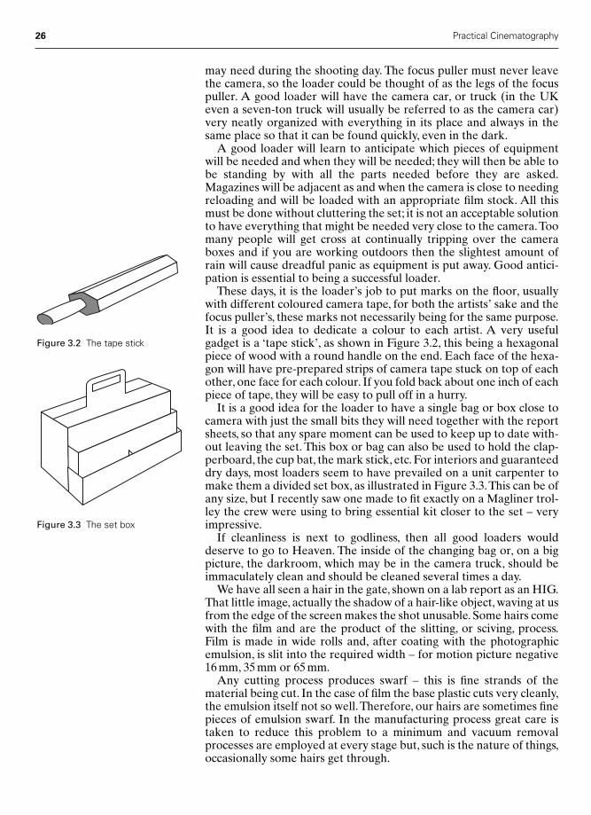
It is a good idea for the loader to have a single bag or box close tocamera with just the small bits they will need together with the reportsheets, so that any spare moment can be used to keep up to date with-out leaving the set. This box or bag can also be used to hold the clap-perboard, the cup bat, the mark stick, etc. For interiors and guaranteeddry days, most loaders seem to have prevailed on a unit carpenter tomake them a divided set box, as illustrated in Figure 3.3.This can be ofany size, but I recently saw one made to fit exactly on a Magliner trol-ley the crew were using to bring essential kit closer to the set – veryimpressive.
If cleanliness is next to godliness, then all good loaders woulddeserve to go to Heaven. The inside of the changing bag or, on a bigpicture, the darkroom, which may be in the camera truck, should beimmaculately clean and should be cleaned several times a day.
We have all seen a hair in the gate, shown on a lab report as an HIG.That little image, actually the shadow of a hair-like object, waving at usfrom the edge of the screen makes the shot unusable. Some hairs comewith the film and are the product of the slitting, or sciving, process.Film is made in wide rolls and, after coating with the photographicemulsion, is slit into the required width – for motion picture negative16 mm, 35 mm or 65 mm.
Any cutting process produces swarf – this is fine strands of thematerial being cut. In the case of film the base plastic cuts very cleanly,the emulsion itself not so well.Therefore, our hairs are sometimes finepieces of emulsion swarf. In the manufacturing process great care istaken to reduce this problem to a minimum and vacuum removalprocesses are employed at every stage but, such is the nature of things,occasionally some hairs get through.
26 Practical Cinematography
Figure 3.2 The tape stick
Figure 3.3 The set box
Chap-03 12/16/04 3:05 PM Page 26
Because the film sometimes arrives at the loader’s bag or darkroomcarrying its little supply of hairs, loaders must be continually vigilant intheir photographic housework. It has been known for a senior mem-ber of the camera crew, when passing the loader’s bag, to turn it insideout and see how clean the corners are. It is no use them claiming theywere going to clean it – it should have been clean. If, after a couple ofinspections at the beginning of the picture, all is well and there arevery few hairs appearing, then the loader will be left in peace.
Perhaps the most important responsibility of the loader is the paper-work. It is boring, but if the camera report sheet is not both legible andaccurate it will be impossible to find the appropriate piece of negativecome neg. cutting. Also, on most pictures the production office will bekeeping a very close eye on the daily camera report sheets. This is forseveral reasons. The shot footage must be logged to see if the produc-tion is on budget in this area and they will want to know how muchfootage is being entered in the waste column. A reputation for goodpaperwork is the most common reason for a production office toapprove the DP’s nomination of a clapper loader. My loader keeps allthe information regarding the lens, exposure, filters, etc. very neatly in alittle book similar to a policeman’s notebook. Should I need to referback to any set-up, he then has the notes for the whole picture in hisback pocket – very efficient.They also keep the notes on filters and thelike to a minimum on the report sheet; this way, my techniques forachieving certain effects are not broadcast to too great an audience.Most DPs like to keep their ways of doing things within the crew, atleast until the picture has been released.
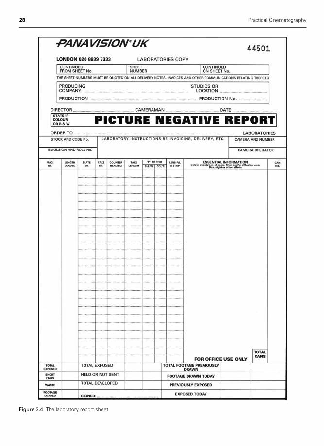
At the end of every day the loader should check with the DP to seeif there are any special notes they want entered on the laboratoryreport sheet. A typical, blank, report sheet is shown in Figure 3.4.
On a 35 mm picture it is the perceived wisdom in the productionoffice that good loaders can save their salaries by intelligent jugglingof which magazines are put on the camera when and thus reduce theamount of wasted film stock. A loader who is efficient in this area getshired again.
The clapper part of the job is deceptively simple. I am appalled athow often a clapperboard is unreadable. It is vital that all the relevantinformation is on the clapperboard and that it is easily read. If youhave ever tried to check the slate on a very blurred board that hasstarted to leave the frame just before the clap is closed you will under-stand why.
Not only should the clapperboard be neat, but it must be put on filmin the correct way. The board should be held very still as the clap stickis brought down and should then be held still for half a second afterthe clap; only then should it be removed. This will give the cuttingroom 12 frames of perfectly sharp board after the clap, which makessynching up the sound and picture very much easier. There is also acorrect way of putting on a mute, or silent, board.The board should beheld by the stick with the stick open and the board should be held onlyby this hand. This shows the cutting room that it is a mute shot as onlyan idiot would now clap the board on their own fingers.
Once, clapperboards were made wholly of wood, originally usingchalk numbers, hence often being referred to as the slate, and later util-izing plastic numbers attached with Velcro. Almost universally thesedays, a board known as a backlight board is used and these are a vast
The camera crew 27
Chap-03 12/16/04 3:05 PM Page 27
28 Practical Cinematography
Figure 3.4 The laboratory report sheet
Chap-03 12/16/04 3:05 PM Page 28
The camera crew 29
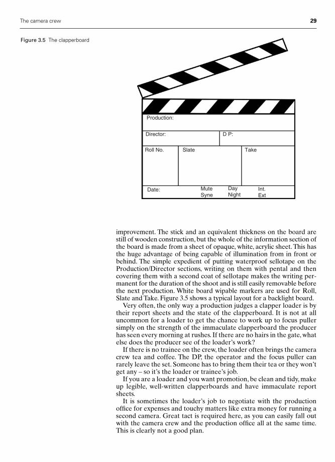
improvement. The stick and an equivalent thickness on the board arestill of wooden construction, but the whole of the information section ofthe board is made from a sheet of opaque, white, acrylic sheet. This hasthe huge advantage of being capable of illumination from in front orbehind. The simple expedient of putting waterproof sellotape on theProduction/Director sections, writing on them with pental and thencovering them with a second coat of sellotape makes the writing per-manent for the duration of the shoot and is still easily removable beforethe next production. White board wipable markers are used for Roll,Slate and Take. Figure 3.5 shows a typical layout for a backlight board.
Very often, the only way a production judges a clapper loader is bytheir report sheets and the state of the clapperboard. It is not at alluncommon for a loader to get the chance to work up to focus pullersimply on the strength of the immaculate clapperboard the producerhas seen every morning at rushes. If there are no hairs in the gate, whatelse does the producer see of the loader’s work?
If there is no trainee on the crew, the loader often brings the cameracrew tea and coffee. The DP, the operator and the focus puller canrarely leave the set. Someone has to bring them their tea or they won’tget any – so it’s the loader or trainee’s job.
If you are a loader and you want promotion, be clean and tidy, makeup legible, well-written clapperboards and have immaculate reportsheets.
It is sometimes the loader’s job to negotiate with the productionoffice for expenses and touchy matters like extra money for running asecond camera. Great tact is required here, as you can easily fall outwith the camera crew and the production office all at the same time.This is clearly not a good plan.
Production:
Director: D P:
Roll No. Slate Take
Date: MuteSyne
DayNight
Int.Ext
Figure 3.5 The clapperboard
Chap-03 12/16/04 3:05 PM Page 29

The focus puller (AC1 or 1st AC)
Keeping the main action sharp is the prime responsibility of the focuspuller. In addition, they are the one most concerned with the cameraitself. It is their task to build the camera each morning and to put itaway at the finish of shooting.They must keep it and the lenses scrupu-lously clean. They must carry out any front-line maintenance on thecamera and its associated kit.
Keeping the main action sharp is done, in the main, by using a tapemeasure, after which the depth of field is calculated using a Kelly cal-culator, Samcine calculator or depth of field charts (see Chapter 16 foran explanation of this). It takes a great deal of talent and experience tobecome a good focus puller, and a fine understanding of exactly whatthe audience will be looking at at any given moment during a scene.
Currently, there is a trend for focus pullers to use infrared rangefinders.They are very accurate if used with skill. My worry about thesedevices is that although many of them say they are perfectly safe, weare in a litigious society. Let us suppose the focus puller had put theinfrared dot on the forehead of a major star and within a few monthsthat star developed any kind of eye problem – would you want to be incourt as the defendant? I would not. Let’s stick to the tape – unless wehave monumental insurance.
When shooting with lenses with very long focal lengths the focuspuller may decide to take an eye focus – that is, focusing the lensthrough the viewfinder. This is because, with long focus lenses, a verysmall movement of the focus barrel of the lens may move the plane offocus quite a long way into the set. Before taking an eye focus it isimportant to know how to set the focus on the eyepiece. First, you rackthe focus to a distance which puts the image as out of focus as can pos-sibly be achieved. You then focus the viewfinder on the cross in themiddle of the viewfinder. If you now refocus the lens you will haveperfect focus.
There is an old trick for obtaining perfect focus that works better insome viewfinders than others. Having obtained what you believe to bea perfectly sharp image, immediately behind the cross in the centre ofthe viewfinder rock your eye very slightly from side to side. If you arein perfect focus the cross and the image will appear to move together.If you can see any apparent movement between the cross and theimage you are not in perfect focus. This is known as parallax focusing,because if you see movement there is a parallax error between theplane of focus of the image and the plane of the cross on the focusingscreen. When the image is perfectly formed on the focusing screen,and is therefore sharp, there will be no difference in the position of theimage and the cross engraved on the screen and therefore no parallaxerror.
There are many tricks of the trade and good focus pullers are worththeir weight in gold, quite literally, for if the focus puller is first classthen the DP may choose to light to a wider aperture and thereby save theproduction a considerable sum on the lighting budget.
The focus puller is responsible for setting the stop on the lens asdirected by the DP.
The focus puller rarely leaves the camera.The operator must be freeto go off with the director and the DP to recce the coming set-ups, etc.The loader will bring the focus puller the bits of kit needed to build the
30 Practical Cinematography
Chap-03 12/16/04 3:05 PM Page 30

camera for the next shot. You could say that, during the shooting day,the camera belongs to the focus puller.
At the end of every printed take the focus puller will check the gatefor any hairs or scratches. If all is well, they will then give whoever ison continuity the details of the shot. This will include the focal lengthof the lens, the focus setting and the stop. On some crews the loaderdoes this, especially if they are keeping very full notes for themselvesor the DP; my loader does this for me.
The camera operator
The duties of the operator may seem self-evident, but have youthought of the many different ways that the operator may be askedto interact with the director, the DP, the rest of the crew and often continuity?
It is common in the UK for a director, after giving initial guidance to the DP and usually in the presence of the operator, to leave the DPto their own devices and to work very closely with the operator. InAmerica, most often, the director only talks to the DP; the DP thendirects the operator.
Vital to the relationship between the DP, the operator and the dir-ector, in the UK way of working, is the ability of the operator to feedback to the DP updates of the director’s requirements, which mayhave happened while the DP was lighting the current set or away pre-lighting another.
When setting camera flags for backlights, etc., the operator must becertain that they are not flagging off light important to the DP’s visionof the scene. A continual dialogue between these two most importanttechnicians is imperative. In the UK, the DP or the gaffer sets the flags,in the USA it’s the grip’s job.
The operator is usually nominated by the DP, but this is a nomin-ation that must always be cleared with the production office. Manydirectors are as concerned to hire the most appropriate operator as theright DP. It sometimes happens that the director will nominate theoperator and ask the DP’s approval.As you will appreciate, for a DP tohave a regular and admired operator can be an advantage to everyone.
While the operator is responsible for all the camera movementsduring the shot, they are not responsible for the physical movement ofthe camera between shots.This falls to the team of focus puller, loaderand grip. During a shot the travelling movement of the camera is theresponsibility of the grip, working under the direction of the operator.
The Director of Photography
Although I started this book with a more detailed description of theDP’s role, I am including here a more general view on the craft inorder to see the DP’s responsibilities within the overall concept of thecamera crew.
The primary responsibility of the DP is to create the mood and feelof the picture with their lighting. Depending on the style of the dir-ector, you may be left to decide the look of the film for yourself or, aftermeetings with the director and, usually, art department, you may then
The camera crew 31
Chap-03 12/16/04 3:05 PM Page 31

be left to light the set as you see fit. Alternatively, the director mayhave very firm ideas as to how the film should look and it will be theDP’s task to fulfil these wishes.All these different ways of working arejust as enjoyable; a little guidance on the set is very fulfilling, but work-ing to a director’s wishes and giving what is wanted, and hopefullymore, brings much praise and loyalty from the director.
As the senior head of department, the DP is looked to to set anexample to the rest of the unit. It is often the personal style of the cine-matographer that will get further work just as much as the quality ofthe photography.Time keeping, crew behaviour, dress and manners allcome, at least in part, from the DP and so they set the standard for theprofessional approach of the crew.
DPs are responsible for all matters pertaining to the photography ofthe film – lighting, exposure, composition, cleanliness, etc. are all, ultim-ately, their responsibility. DPs will more often than not nominate thecrew – that is, they will have put into the production office a list of firstchoice and second choice people to be offered the job. If a crew mem-ber is nominated by the DP, then the DP is responsible for them andwill in all probability have to decide whether they are to be fired ifthey are not up to the required standard.The upside of this is that DPsusually get the crews they want.
It should be said that it is quite common these days for the DP’scontract to include the requirement to provide a ‘full negative’. Thismeans that underexposure as a route to providing a certain look isunacceptable to the production. You may find this offensive orrestricting, but I am afraid that many producers have had a consider-able amount of trouble producing first-class release prints.Though therushes may look excellent, cinema release prints are usually madefrom internegatives, as the original negative is far too precious to usefor final printing of the large quantity of prints needed by the distribu-tor (see Chapter 8). It is very difficult to make a satisfactory inter-negative from a thin or underexposed camera negative.
It is not at all uncommon for an appreciable part of the production’sbudget to come from pre-selling the video rights. A full negative isvital in these circumstances, as the telecine machines used to make themaster tape are very intolerant of a thin negative.
I am including all this because cinematographers should get used toproducing a correctly exposed negative – bad habits formed early maylead to considerable periods of unemployment later.
The grip or dolly grip
The grip is primarily responsible for the camera dolly and all themovements made by it. They are also responsible for moving the tri-pod to the next set-up; the focus puller will usually take the camera.Never move a camera while it is still on the tripod. I have seen one falloff in these circumstances – not a pretty sight and very embarrassing.
The grip is responsible for building, or supervising the building of,any construction needed to support the track or boards the dolly isgoing to run on. The levelling and smoothness of the dolly’s workingsurface is vital to the success of a dolly shot.
Front-line maintenance of the dolly and its kit are down to the grip.Very often, they will have built or had built many special bits to enable
32 Practical Cinematography
Chap-03 12/16/04 3:05 PM Page 32
them to fix a camera to almost any object. A good and experiencedgrip’s van is an Aladdin’s cave.
The gaffer
The gaffer is the chief electrician and works directly for the DP. SomeDPs will set their own flags and barn doors and some won’t – it justdepends on how they like to work together.Very often, the DP will becloser to his gaffer than any other member of the crew. They are vitalto his success.
It is said that one very well known and much respected AmericanDP, when asked by a student what was the single most important thingthey could do to improve their photography, replied ‘hire the bestgaffer you can afford, even if you have to give them part of your fee’.I must say I agree with that advice.
The best boy is simply the gaffer’s best boy. On a large crew, thegaffer will plot the cable runs and how to fix and support the lamps –it’s the best boy’s job to organize the lighting crew and actually moveand fix the lamps. On most small units, say three sparks in total, thegaffer acts as his own best boy.
My gaffer and I do most of the tweaking between us, unless it is a bigset where I leave it entirely to my gaffer and his best boy. My regulargaffer is so good and understands lighting so well that I will often askhim to light simple set-ups without me there and without a plot. I justhave to give him an idea of how I want the artists to look and themood of the scene, perhaps adding where a main key light should be.On larger set-ups, I give him a floor plan of the set with all the mainlamps marked on it; this is then known as the lighting plot, and oftenhe will have to go off with this and put in a very big pre-light withoutme, as I need to stay with the principal artists.
Crew protocol
On any film set, the camera crew always arrive at least half an hourbefore the call on the call sheet.The camera will be built and ready onthe tripod or dolly before the call time and will be positioned roughlywhere the first shot of the day is expected. Breakfast is usually takenafter the camera is prepared. It will not be taken after the call; if youarrive too late for breakfast, tough, the camera comes first. It is yourresponsibility to be on time. More technicians lose work through badtimekeeping than anything else, so don’t be late – be half an hour earlyand get into the habit.
On a feature film, it is traditional for all the other technicians to callthe DP and the director ‘Sir’; the DP very often calls the director ‘Sir’ aswell, perhaps because in the first few days he can’t remember theirname and the habit just sticks. You may not approve but you may alsoget fired if you don’t. If ‘Sir’ has become your habit, then working withlady directors or DPs can cause embarrassment; wait and see what theyseem to prefer. I know one lady director who likes to be called ‘Skipper’,but I wouldn’t try that unless you are very, very sure she will like it.
If you show respect to others you are likely to receive it in return –film sets are not unlike the rest of life.
The camera crew 33
Chap-03 12/16/04 3:05 PM Page 33

This page intentionally left blank

Part Two
The Technology
Chap-04 2/8/05 1:08 PM Page 35

This page intentionally left blank
4
The motion picturecamera
Man has been beguiled by the movies for over a century now. One rea-son might be that it takes a disarmingly simple piece of equipment, themotion picture camera, to record images from the most fertile of ourimaginations.
In essence, a motion picture camera is a couple of boxes, one with alens on the front and a mechanism inside capable of dragging a lengthof film down a specific distance at least 16 times a second, and theother containing a suitable length of film to feed the mechanism withspace remaining to take up the film after exposure.
When the pictures from this device are projected by a similar mech-anism they give a valid representation of the original scene, with all themovements contained therein correctly displayed in a realistic way.
The persistence of vision
Producing moving images from a length of still pictures relies on whatmight be considered an aberration in the process of human vision. Ifan image is flashed upon the retina of the eye the person sees thatimage, briefly, in its entirety and then, over a short period, the imagestays with the person while growing fainter or decaying. If a secondimage is flashed on the retina, soon enough the person will see the twoimages as a continuous image without the first flash.
If there is movement in the interval between the flashing of theimages, the brain will perceive the difference between the two imagesas continuous movement providing the time gap between the twoimages is short enough. If a continuous stream of images is flashedupon the retina in a quick enough succession, then the person will per-ceive no flashing effects and will perceive the images as a continuous,smooth motion.
The rate of image flashing at which the eye starts to perceive motionis around ten flashes per second, though at this rate a flickering effectwill be very noticeable. Only at around 16 or 18 new images per second
37
Chap-04 2/8/05 1:08 PM Page 37

does the movement become truly believable, as continuous motionand the flickering effect reduce to the point where it can be ignored.
Figure 4.1 shows a series of images as they decay, represented by thevertical frames, and the frequency with which the images must bereplaced for the observer to believe that they are seeing a smooth,continuous motion, represented by the horizontal frames.
Frame rates
At the turn of the century, a taking frame rate of 16 frames per second(fps) was becoming common practice. At this time, both cameras andprojectors were still very much hand cranked and most were gearedsuch that a constant cranking speed of two turns per second resulted inthis frame rate, which was very convenient. Those in the industry whowere beginning to consider themselves artists would have preferred ahigher rate, since this reduced the flicker on the screen, hence thephrase ‘going to the flicks’. The film producers and distributors, on theother hand, were seriously opposed to an increase in frame rate, as thiswould use more film and therefore put up costs. Little has changed.
By 1926, the American Society of Motion Picture Engineers (SMPT,later the SMPTE) Standards and Nomenclature Committee recom-mended camera cranking speeds as follows:
Regarding camera speed we recommend as a recommended practice: acamera cranking speed of 60 feet per minute (16 fps), with a minimumof 55 feet and a maximum of 65 feet when normal action is desired, inconnection with the Society of Motion Picture Engineers recommendedpractice of 80 feet per minute projection speed (21 fps).
To recommend different taking and projection speeds may now seemridiculous, but what they were trying to do was to set a standard for aframe rate that was perceived to be correct on viewing.Try turning thesound off on your television and notice how the action suddenly seemsto be slower, despite your certain knowledge that it cannot be. Itwould be uncharitable to think that the theatre owners were keen to
38 Practical Cinematography
Decayof imageon retina
Succession of images displayed on retina
Figure 4.1 The decay of an imageon the human retina
Chap-04 2/8/05 1:08 PM Page 38
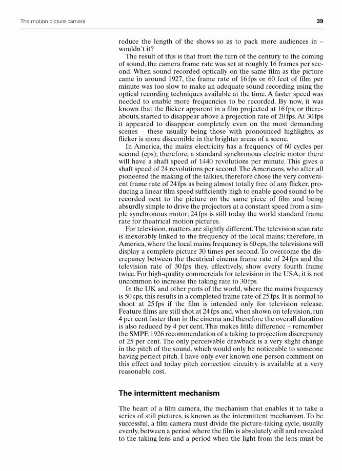
reduce the length of the shows so as to pack more audiences in –wouldn’t it?
The result of this is that from the turn of the century to the comingof sound, the camera frame rate was set at roughly 16 frames per sec-ond. When sound recorded optically on the same film as the picturecame in around 1927, the frame rate of 16 fps or 60 feet of film perminute was too slow to make an adequate sound recording using theoptical recording techniques available at the time. A faster speed wasneeded to enable more frequencies to be recorded. By now, it wasknown that the flicker apparent in a film projected at 16 fps, or there-abouts, started to disappear above a projection rate of 20 fps.At 30 fpsit appeared to disappear completely even on the most demandingscenes – these usually being those with pronounced highlights, asflicker is more discernible in the brighter areas of a scene.
In America, the mains electricity has a frequency of 60 cycles persecond (cps); therefore, a standard synchronous electric motor therewill have a shaft speed of 1440 revolutions per minute. This gives ashaft speed of 24 revolutions per second.The Americans, who after allpioneered the making of the talkies, therefore chose the very conveni-ent frame rate of 24 fps as being almost totally free of any flicker, pro-ducing a linear film speed sufficiently high to enable good sound to berecorded next to the picture on the same piece of film and beingabsurdly simple to drive the projectors at a constant speed from a sim-ple synchronous motor; 24 fps is still today the world standard framerate for theatrical motion pictures.
For television, matters are slightly different.The television scan rateis inexorably linked to the frequency of the local mains; therefore, inAmerica, where the local mains frequency is 60 cps, the televisions willdisplay a complete picture 30 times per second. To overcome the dis-crepancy between the theatrical cinema frame rate of 24 fps and thetelevision rate of 30 fps they, effectively, show every fourth frametwice. For high-quality commercials for television in the USA, it is notuncommon to increase the taking rate to 30 fps.
In the UK and other parts of the world, where the mains frequencyis 50 cps, this results in a completed frame rate of 25 fps. It is normal toshoot at 25 fps if the film is intended only for television release.Feature films are still shot at 24 fps and, when shown on television, run4 per cent faster than in the cinema and therefore the overall durationis also reduced by 4 per cent. This makes little difference – rememberthe SMPE 1926 recommendation of a taking to projection discrepancyof 25 per cent. The only perceivable drawback is a very slight changein the pitch of the sound, which would only be noticeable to someonehaving perfect pitch. I have only ever known one person comment onthis effect and today pitch correction circuitry is available at a veryreasonable cost.
The intermittent mechanism
The heart of a film camera, the mechanism that enables it to take aseries of still pictures, is known as the intermittent mechanism. To besuccessful, a film camera must divide the picture-taking cycle, usuallyevenly, between a period where the film is absolutely still and revealedto the taking lens and a period when the light from the lens must be
The motion picture camera 39
Chap-04 2/8/05 1:08 PM Page 39
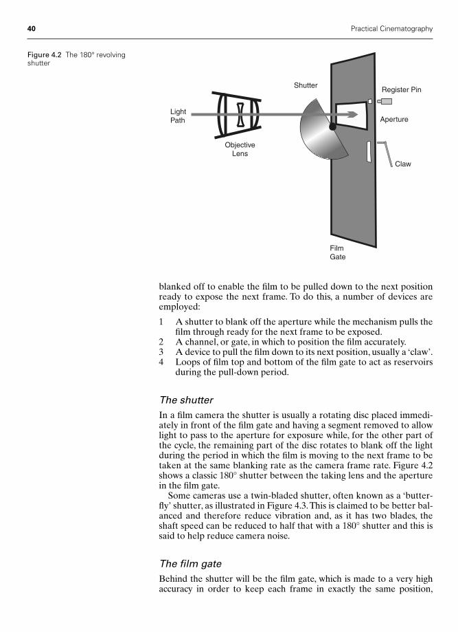
blanked off to enable the film to be pulled down to the next positionready to expose the next frame. To do this, a number of devices areemployed:
1 A shutter to blank off the aperture while the mechanism pulls thefilm through ready for the next frame to be exposed.
2 A channel, or gate, in which to position the film accurately.3 A device to pull the film down to its next position, usually a ‘claw’.4 Loops of film top and bottom of the film gate to act as reservoirs
during the pull-down period.
The shutterIn a film camera the shutter is usually a rotating disc placed immedi-ately in front of the film gate and having a segment removed to allowlight to pass to the aperture for exposure while, for the other part ofthe cycle, the remaining part of the disc rotates to blank off the lightduring the period in which the film is moving to the next frame to betaken at the same blanking rate as the camera frame rate. Figure 4.2shows a classic 180° shutter between the taking lens and the aperturein the film gate.
Some cameras use a twin-bladed shutter, often known as a ‘butter-fly’ shutter, as illustrated in Figure 4.3.This is claimed to be better bal-anced and therefore reduce vibration and, as it has two blades, theshaft speed can be reduced to half that with a 180° shutter and this issaid to help reduce camera noise.
The film gateBehind the shutter will be the film gate, which is made to a very highaccuracy in order to keep each frame in exactly the same position,
40 Practical Cinematography
Aperture
Shutter
ObjectiveLens
FilmGate
LightPath
Claw
Register Pin
Figure 4.2 The 180° revolvingshutter
Chap-04 2/8/05 1:08 PM Page 40
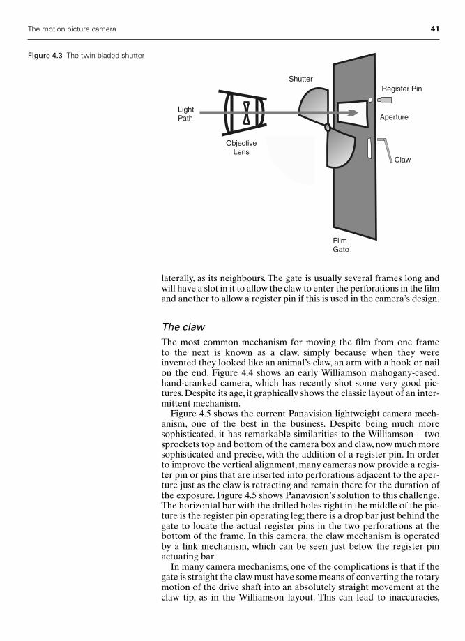
laterally, as its neighbours. The gate is usually several frames long andwill have a slot in it to allow the claw to enter the perforations in the filmand another to allow a register pin if this is used in the camera’s design.
The clawThe most common mechanism for moving the film from one frame to the next is known as a claw, simply because when they wereinvented they looked like an animal’s claw, an arm with a hook or nailon the end. Figure 4.4 shows an early Williamson mahogany-cased,hand-cranked camera, which has recently shot some very good pic-tures. Despite its age, it graphically shows the classic layout of an inter-mittent mechanism.
Figure 4.5 shows the current Panavision lightweight camera mech-anism, one of the best in the business. Despite being much moresophisticated, it has remarkable similarities to the Williamson – twosprockets top and bottom of the camera box and claw, now much moresophisticated and precise, with the addition of a register pin. In orderto improve the vertical alignment, many cameras now provide a regis-ter pin or pins that are inserted into perforations adjacent to the aper-ture just as the claw is retracting and remain there for the duration ofthe exposure. Figure 4.5 shows Panavision’s solution to this challenge.The horizontal bar with the drilled holes right in the middle of the pic-ture is the register pin operating leg; there is a drop bar just behind thegate to locate the actual register pins in the two perforations at thebottom of the frame. In this camera, the claw mechanism is operatedby a link mechanism, which can be seen just below the register pinactuating bar.
In many camera mechanisms, one of the complications is that if thegate is straight the claw must have some means of converting the rotarymotion of the drive shaft into an absolutely straight movement at theclaw tip, as in the Williamson layout. This can lead to inaccuracies,
The motion picture camera 41
Aperture
Shutter
ObjectiveLens
FilmGate
LightPath
Claw
Register Pin
Figure 4.3 The twin-bladed shutter
Chap-04 2/8/05 1:08 PM Page 41

42 Practical Cinematography
Figure 4.4 An early Williamsoncamera mechanism
vibration and noise. The Panavision mechanism echoes the earlierMitchell mechanism in curving the bottom of the gate so that the clawis only required to follow this curved portion of the gate. This designleads to a very vibration-free claw movement of superb accuracy,which is incredibly quiet.
The claw mechanism has to be made to the highest possible toler-ances, as the distance each frame is moved must be identical and mustbe repeated, exactly, every time. When you realize that, during a 10-minute roll of film, the claw will have pulled 16 000 frames of filmthrough the camera, you get some impression of both the precisionand durability required of the claw mechanism.
The loopBetween the box holding the reserve and used film, known as the filmmagazine, and the box containing the camera mechanism and the camera gate will be one or two sprocket wheels with teeth that engage
Chap-04 2/8/05 1:08 PM Page 42
with the film’s perforations and geared to the claw mechanism, thusensuring a constant supply of film both to the gate and taking the filmaway after exposure. As the sprocket will be running continuously andthe claw only acts intermittently above and below the gate, the film isallowed to form loops.The loop above the gate forms a reservoir of filmready for the claw to pull it through the gate; this action then enlargesthe loop at the bottom of the gate ready for the sprocket to take it away.
The complete cycle of an intermittent movement is shown in Figure4.6. In film strip A, the frame being exposed is just coming to the endof its full exposure. The shutter is starting to close, the claw is enteringthe appropriate perforation and the register pin is withdrawing. In filmstrip B, the shutter is closed, the register pin is fully retracted and theclaw is commencing the pull-down. In film strip C, the shutter is stillclosed, the register pin still withdrawn and the claw is halfway throughthe pull-down. In film strip D, the shutter is still closed, the register pinstill withdrawn but the claw is nearing the end of its travel and startingto slow down. In film strip E, the film has come to rest, the shutter isstarting to open, the claw is withdrawing and the register pin is nearlyfully in to its perforation. In film strip F, the shutter is fully open, thusstarting the exposure, the register pin is fully locked into its perfora-tion, thus holding the frame being exposed absolutely still, and theclaw is travelling upwards behind the gate to return to the top of itstravel. In film strip G, the shutter is still open, the register pin is still inand the claw has nearly reached its topmost position. In film strip H,the shutter has closed, the register pin has withdrawn and the claw hasentered the perforation relating to the next frame and is just startingits pull-down. The cycle is now complete – the mechanism is back tofilm strip B and will now commence the whole cycle again.
The reflex viewfinder
Early film cameras had viewfinders either by the side or above the tak-ing lens. The viewfinder, therefore, didn’t see exactly the same frame
The motion picture camera 43
Figure 4.5 The Panavisionlightweight camera mechanism
Chap-04 2/8/05 1:08 PM Page 43

as the cameras lens. This is known as parallax error, as the optical axisof the taking lens and that of the viewfinder will point in the samedirection but will run parallel to each other. This problem was firstovercome when a German company, Arnold & Richter, introducedtheir Arriflex 35 mirror reflex camera to the world at the 1937 LeipzigFair. This camera totally revolutionized the way film cameras weredesigned from then on.
The Arriflex did not have its shutter running flat to, and in the sameplane as, the film gate but had it angled at 45° to the gate and the aper-ture. Furthermore, the front surface of the shutter had a mirrored sur-face, so that when the shutter was closed the light that was blocked fromthe aperture was now sent off at a right angle. This image was then dis-played on a ground glass whose distance from the lens, via the mirroredshutter, was exactly the same as the film aperture.A second fixed mirror,or prism, then sent the image on the ground glass to the viewfinderoptics.Thus, the image in the viewfinder was identical to that on the film,as they shared the light from the lens on an alternating basis.
The original Arriflex was organized so that the mirrored shuttersent the light horizontally to the viewfinder. Today, cameras dividebetween those that send it horizontally and those that have theshutter beneath the lens and send it upwards to the viewfinder.Interestingly, Arriflex have made cameras with both configurations.Figure 4.7 shows the arrangement of a reflex viewfinder where thelight is sent upwards.
44 Practical Cinematography
A B C D E F G H
ShutterOPEN
ShutterOPEN
ShutterOPEN
ShutterOPEN
ShutterCLOSED
ShutterCLOSED
ShutterCLOSED
ShutterCLOSED
Figure 4.6 The claw and register pin cycle
Chap-04 2/8/05 1:08 PM Page 44

Viewing screens
The ground glass viewing screens of the early reflex cameras have nowbeen replaced with a slice of an end-on bunch of fibre-optics cut, andground flat, to produce a focusing screen. This greatly reducesvignetting at the edges of the image, is much more critical of exactfocus so that the camera operator can determine the focus more eas-ily, forms an image far brighter than a ground glass and has less bright-ness fall-off in the corners of the frame.
There is a very reliable way of setting your eyepiece to your naturalvision. Point the camera at an object less than six feet, or two metres,away, and now rack the lens to infinity – use a lens of at least the‘normal’ focal length and focus the viewfinder ocular on the cross inthe middle of the viewfinder, if there isn’t a cross focus on the linearound the viewfinder mask. Now refocus on the scene and you will beable to eye focus perfectly.
The film magazine
In order to be able to change from one roll of film to another at anytime, both the feed roll of film and the take-up roll are housed in alight-tight container provided with a light trap, through which the filmcan exit and re-enter the box – this assembly is known as the filmmagazine.
Two configurations of magazine are common today. The first is thedisplacement magazine, where both rolls are held in a single chamber,as shown in Figure 4.8.The displacement magazine takes advantage of
The motion picture camera 45
Fibre OpticFocusing Screen
ViewfinderOptics
Eye
Mirror
MirrorShutter
FilmGate
ObjectiveLens
Light
Path
Figure 4.7 The mirror reflexviewfinder
Chap-04 2/8/05 1:08 PM Page 45

the fact that while the take-up roll is getting larger, as film is exposed,the feed roll is decreasing in diameter. In Figure 4.8, the dotted linesrepresent where a full feed roll and a full take-up roll would sit in themagazine. Clearly, there is not enough room for both of them. By care-fully siting the hubs that will hold the plastic cores the film will comeon, the magazine can be laid out so that even if the feed and take-uprolls do get close to each other they will never actually touch.
This has two advantages: firstly, the magazine will be smaller than adesign not taking advantage of the displacement effect; secondly, thewhole device will be lighter, this being particularly valuable when thecamera is to be hand-held or fitted to a steadycam rig.
At the bottom of the magazine illustrated in Figure 4.8 can be seena light trap. This may consist of either a sprocket or large felt roller inits centre, with four felt rollers, two on the film side and two on thedaylight side of the complete trap. By arranging light baffles withinand around this arrangement, the designer can ensure that no lightfrom the outside can enter the film chamber even in the brightestsunlight.
If a sprocket is used in the light trap then, when loading the film inthe dark, the size of the film loop on the outside of the magazine willhave to be carefully set. If the light trap uses only felt rollers, thenthere is no need to establish an exact loop size when loading themagazine. When this type of magazine is fitted to the camera, havinglaced the film around the camera’s mechanism, either the take-up rollwill have to be tensioned by hand or, on some cameras, a lace button ispressed and the magazine feed and take-up motors automaticallyadjust the spare film, exiting and entering the light trap to exactly theright tension.
An alternative layout is the coaxial magazine. Here the feed andtake-up rolls sit side by side, and an arrangement of sprockets androllers deliver the film to the camera gate in the necessary straight linepath. A representation of this can be seen in Figure 4.9.
46 Practical Cinematography
FeedRoll
Take upRoll
Film Loop
Light Trap
Figure 4.8 The displacement filmmagazine
Feed
Take Up
Figure 4.9 The film path of a coaxialmagazine
Chap-04 2/8/05 1:08 PM Page 46
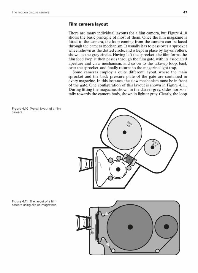
Film camera layout
There are many individual layouts for a film camera, but Figure 4.10shows the basic principle of most of them. Once the film magazine isfitted to the camera, the loop coming from the camera can be lacedthrough the camera mechanism. It usually has to pass over a sprocketwheel, shown as the dotted circle, and is kept in place by lay-on rollers,shown as the grey circles. Having left the sprocket, the film forms thefilm feed loop; it then passes through the film gate, with its associatedaperture and claw mechanism, and so on to the take-up loop, backover the sprocket, and finally returns to the magazine light trap.
Some cameras employ a quite different layout, where the mainsprocket and the back pressure plate of the gate are contained inevery magazine. In this instance, the claw mechanism must be in frontof the gate. One configuration of this layout is shown in Figure 4.11.During fitting the magazine, shown in the darker grey, slides horizon-tally towards the camera body, shown in lighter grey. Clearly, the loop
The motion picture camera 47
FeedRoll
Take upRoll
Figure 4.10 Typical layout of a filmcamera
Figure 4.11 The layout of a filmcamera using clip-on magazines
Chap-04 2/8/05 1:08 PM Page 47

size and its position relative to the gate must be carefully set beforethe magazine is fitted, and this makes for a slightly more difficult load-ing procedure in the dark. Many cameramen feel that the advantagesof almost instant camera reloads and smaller overall camera confi-guration more than make up for the slight complication in loading themagazines.
Magazines for this type of layout are often of the displacement type,though some have a configuration of clip-on and coaxial layout, theArri 16 SR III being one such. The Aaton 35 III takes the concept ofdisplacement one stage further by actually moving the position of thetake-up hub during filming, so that the maximum distance betweenthe hubs can be reduced still further, thus making the magazine evensmaller and lighter in this very compact and elegant 35 mm camera.
48 Practical Cinematography
Chap-04 2/8/05 1:08 PM Page 48

5
Lenses
Artistic decisions
When you come to order a lens set for a picture, you are faced with anumber of interesting problems and choices. These relate to:● Definition or sharpness.● Speed or maximum aperture.● Contrast, or how quickly does black become white?● Do you need prime lenses, a zoom or both?● What focal lengths do you need? Should you include extreme wide
angle or telephoto?
Lenses have developed dramatically over the last 20 years. During thistime there have been two areas where lens designers have con-centrated their efforts – speed and definition. In doing this, they havedeveloped some amazing lenses but we, as artists, do not always wantenormously high definition images nor always need a large maximumaperture.
It is common, especially on feature films these days, to shoot withsome kind of diffusion filter on the lens – so why do we assume thatthe character of the picture will be what we desire when a high definitionlens has some of that definition destroyed by a filter? Could we notchoose a lens that has the natural characteristic we desire withoutneeding the filter – and would that be an advantage?
Characteristics of lensesToday, we think of our lenses in very critical technical terms. However,it is as interesting to think of their emotional character. What followsmust, of its nature, be broad generalizations and very much my per-sonal opinion:● German lenses are crisp, analytical and fast. Clinical, even.● English prime lenses are traditionally warm, emotional, have dark
moody shadows and come with a relatively high definition.● The English Cooke zooms are very gracious in their shadow ren-
dition. I am biased, for if I am going to use a zoom then it is mostlikely to be a Cooke.The Cooke 18–100 mm T3 zoom for 35 mm is,
49
Chap-05 2/8/05 11:24 AM Page 49
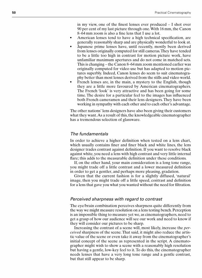
in my view, one of the finest lenses ever produced – I shot over 90 per cent of my last picture through one.With 16 mm, the Canon8–64 mm zoom is also a fine lens that I use a lot.
● American lenses tend to have a high technical specification, aregenerally reasonably sharp and are physically wonderful to look at.
● Japanese prime lenses have, until recently, mostly been derivedfrom lenses originally computed for still cameras.They have tendedto be a little too high in contrast for motion picture work, haveunfamiliar maximum apertures and do not come in matched sets.This is changing – the Canon 8–64 mm zoom mentioned earlier wasoriginally computed for video use but has adapted to motion pic-tures superbly. Indeed, Canon lenses do seem to suit cinematogra-phy better than most lenses derived from the stills and video world.
● French lenses are, in the main, a mystery to the English, thoughthey are a little more favoured by American cinematographers.The French ‘look’ is very attractive and has been going for sometime. The desire for a particular feel to the images has influencedboth French cameramen and their lens designers. They have beenworking in sympathy with each other and to each other’s advantage.
The other nations’ lens designers have also been giving their customerswhat they want.As a result of this, the knowledgeable cinematographerhas a tremendous selection of glassware.
The fundamentalsIn order to achieve a higher definition when tested on a lens chart,which usually contains finer and finer black and white lines, the lensdesigner trades contrast against definition. If you want to resolve blackagainst white, you need a lens with high contrast and very little internalflare; this adds to the measurable definition under these conditions.
If, on the other hand, your main consideration is a long tone range,you might trade off a little contrast and a lower measured definition in order to get a gentler, and perhaps more pleasing, gradation.
Given that the current fashion is for a slightly diffused, ‘natural’image, then you might trade off a little speed, contrast and definitionfor a lens that gave you what you wanted without the need for filtration.
Perceived sharpness with regard to contrastThe eye/brain combination perceives sharpness quite differently fromthe way we might measure resolution on a lens testing bench. Perceptionis an impossible thing to measure yet we, as cinematographers, need toget a grasp of how our audience will see our work and need to know ifthey will consider our pictures to be sharp.
Increasing the contrast of a scene will, most likely, increase the per-ceived sharpness of the scene. That said, it might also reduce the artis-tic value of the scene or even take it away from the cinematographer’sinitial concept of the scene as represented in the script. A cinemato-grapher might wish to show a scene with a reasonably high resolutionbut having a gentle, low-key feel to it. To do this, the cinematographerneeds lenses that have a very long tone range and a gentle contrast,but that still appear to be sharp.
50 Practical Cinematography
Chap-05 2/8/05 11:24 AM Page 50
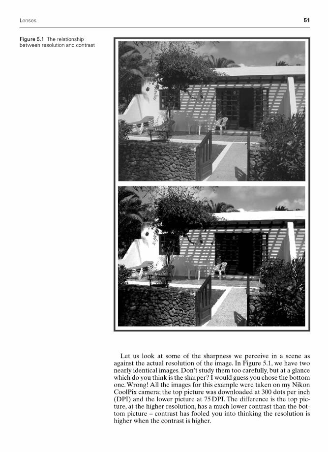
Let us look at some of the sharpness we perceive in a scene asagainst the actual resolution of the image. In Figure 5.1, we have twonearly identical images. Don’t study them too carefully, but at a glancewhich do you think is the sharper? I would guess you chose the bottomone. Wrong! All the images for this example were taken on my NikonCoolPix camera; the top picture was downloaded at 300 dots per inch(DPI) and the lower picture at 75 DPI. The difference is the top pic-ture, at the higher resolution, has a much lower contrast than the bot-tom picture – contrast has fooled you into thinking the resolution ishigher when the contrast is higher.
Lenses 51
Figure 5.1 The relationshipbetween resolution and contrast
Chap-05 2/8/05 11:24 AM Page 51
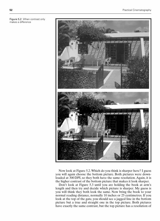
Now look at Figure 5.2.Which do you think is sharper here? I guessyou will again choose the bottom picture. Both pictures were down-loaded at 300 DPI, so they both have the same resolution. Again, it isthe higher contrast of the bottom picture that makes it look sharper.
Don’t look at Figure 5.3 until you are holding the book at arm’slength and then try and decide which picture is sharper. My guess isyou will think they both look the same. Now bring the book to yournormal reading distance, normally 10 inches or 25 centimetres. If youlook at the top of the gate, you should see a jagged line in the bottompicture but a true and straight one in the top picture. Both pictureshave exactly the same contrast, but the top picture has a resolution of
52 Practical Cinematography
Figure 5.2 When contrast onlymakes a difference
Chap-05 2/8/05 11:24 AM Page 52
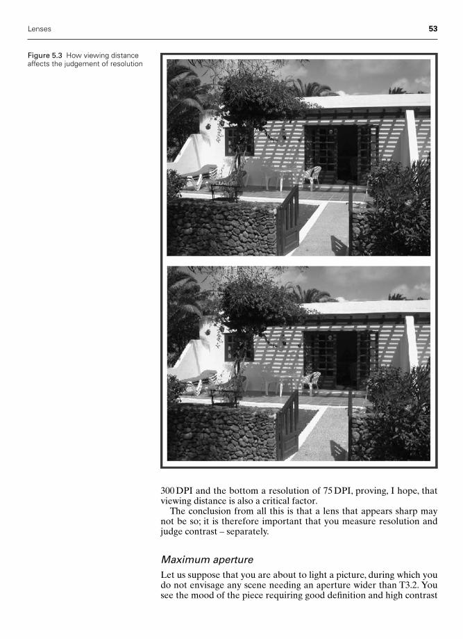
300 DPI and the bottom a resolution of 75 DPI, proving, I hope, thatviewing distance is also a critical factor.
The conclusion from all this is that a lens that appears sharp maynot be so; it is therefore important that you measure resolution andjudge contrast – separately.
Maximum apertureLet us suppose that you are about to light a picture, during which youdo not envisage any scene needing an aperture wider than T3.2. Yousee the mood of the piece requiring good definition and high contrast
Lenses 53
Figure 5.3 How viewing distanceaffects the judgement of resolution
Chap-05 2/8/05 11:24 AM Page 53
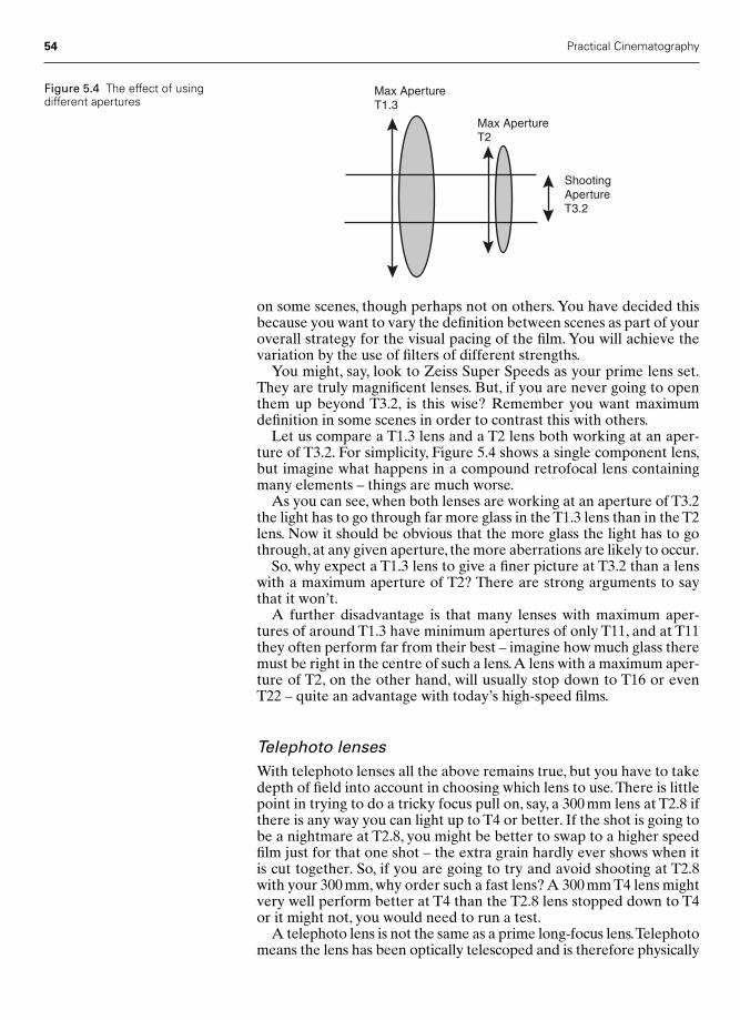
on some scenes, though perhaps not on others. You have decided thisbecause you want to vary the definition between scenes as part of youroverall strategy for the visual pacing of the film. You will achieve thevariation by the use of filters of different strengths.
You might, say, look to Zeiss Super Speeds as your prime lens set.They are truly magnificent lenses. But, if you are never going to openthem up beyond T3.2, is this wise? Remember you want maximumdefinition in some scenes in order to contrast this with others.
Let us compare a T1.3 lens and a T2 lens both working at an aper-ture of T3.2. For simplicity, Figure 5.4 shows a single component lens,but imagine what happens in a compound retrofocal lens containingmany elements – things are much worse.
As you can see, when both lenses are working at an aperture of T3.2the light has to go through far more glass in the T1.3 lens than in the T2lens. Now it should be obvious that the more glass the light has to gothrough, at any given aperture, the more aberrations are likely to occur.
So, why expect a T1.3 lens to give a finer picture at T3.2 than a lenswith a maximum aperture of T2? There are strong arguments to saythat it won’t.
A further disadvantage is that many lenses with maximum aper-tures of around T1.3 have minimum apertures of only T11, and at T11they often perform far from their best – imagine how much glass theremust be right in the centre of such a lens.A lens with a maximum aper-ture of T2, on the other hand, will usually stop down to T16 or evenT22 – quite an advantage with today’s high-speed films.
Telephoto lensesWith telephoto lenses all the above remains true, but you have to takedepth of field into account in choosing which lens to use.There is littlepoint in trying to do a tricky focus pull on, say, a 300 mm lens at T2.8 ifthere is any way you can light up to T4 or better. If the shot is going tobe a nightmare at T2.8, you might be better to swap to a higher speedfilm just for that one shot – the extra grain hardly ever shows when itis cut together. So, if you are going to try and avoid shooting at T2.8with your 300 mm, why order such a fast lens? A 300 mm T4 lens mightvery well perform better at T4 than the T2.8 lens stopped down to T4or it might not, you would need to run a test.
A telephoto lens is not the same as a prime long-focus lens.Telephotomeans the lens has been optically telescoped and is therefore physically
54 Practical Cinematography
ShootingApertureT3.2
Max ApertureT2
Max ApertureT1.3
Figure 5.4 The effect of usingdifferent apertures
Chap-05 2/8/05 11:24 AM Page 54
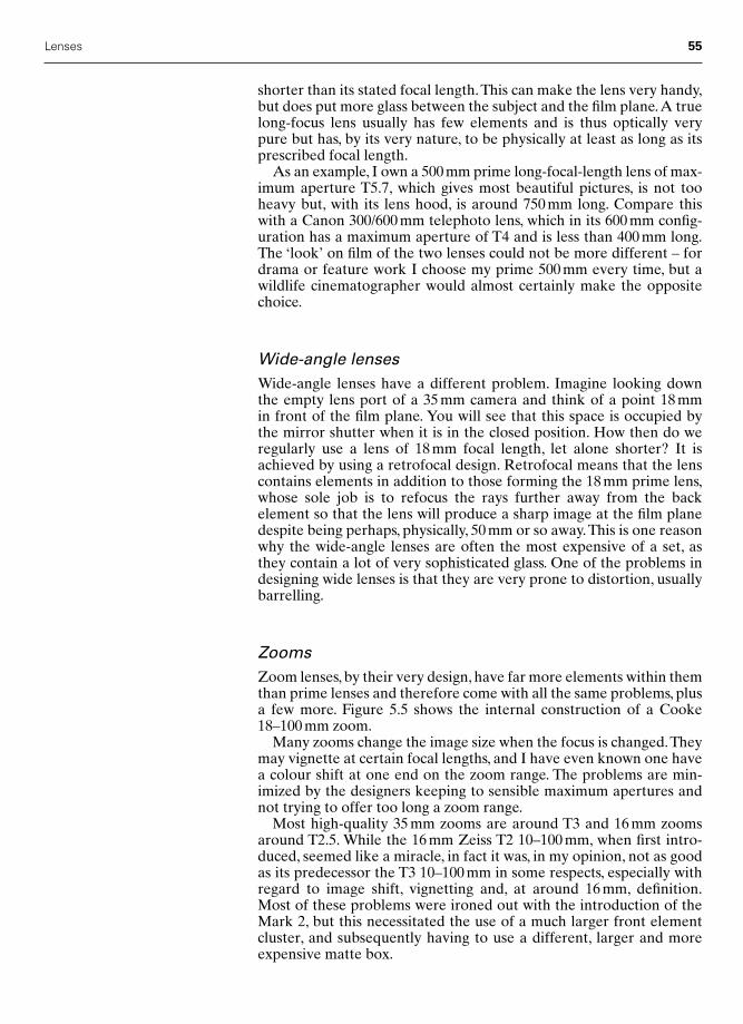
shorter than its stated focal length.This can make the lens very handy,but does put more glass between the subject and the film plane.A truelong-focus lens usually has few elements and is thus optically verypure but has, by its very nature, to be physically at least as long as itsprescribed focal length.
As an example, I own a 500 mm prime long-focal-length lens of max-imum aperture T5.7, which gives most beautiful pictures, is not tooheavy but, with its lens hood, is around 750 mm long. Compare thiswith a Canon 300/600 mm telephoto lens, which in its 600 mm config-uration has a maximum aperture of T4 and is less than 400 mm long.The ‘look’ on film of the two lenses could not be more different – fordrama or feature work I choose my prime 500 mm every time, but awildlife cinematographer would almost certainly make the oppositechoice.
Wide-angle lensesWide-angle lenses have a different problem. Imagine looking downthe empty lens port of a 35 mm camera and think of a point 18 mm in front of the film plane. You will see that this space is occupied by the mirror shutter when it is in the closed position. How then do weregularly use a lens of 18 mm focal length, let alone shorter? It isachieved by using a retrofocal design. Retrofocal means that the lenscontains elements in addition to those forming the 18 mm prime lens,whose sole job is to refocus the rays further away from the back element so that the lens will produce a sharp image at the film planedespite being perhaps, physically, 50 mm or so away.This is one reasonwhy the wide-angle lenses are often the most expensive of a set, asthey contain a lot of very sophisticated glass. One of the problems indesigning wide lenses is that they are very prone to distortion, usuallybarrelling.
ZoomsZoom lenses, by their very design, have far more elements within themthan prime lenses and therefore come with all the same problems, plusa few more. Figure 5.5 shows the internal construction of a Cooke18–100 mm zoom.
Many zooms change the image size when the focus is changed.Theymay vignette at certain focal lengths, and I have even known one havea colour shift at one end on the zoom range. The problems are min-imized by the designers keeping to sensible maximum apertures andnot trying to offer too long a zoom range.
Most high-quality 35 mm zooms are around T3 and 16 mm zoomsaround T2.5. While the 16 mm Zeiss T2 10–100 mm, when first intro-duced, seemed like a miracle, in fact it was, in my opinion, not as goodas its predecessor the T3 10–100 mm in some respects, especially withregard to image shift, vignetting and, at around 16 mm, definition.Most of these problems were ironed out with the introduction of theMark 2, but this necessitated the use of a much larger front elementcluster, and subsequently having to use a different, larger and moreexpensive matte box.
Lenses 55
Chap-05 2/8/05 11:24 AM Page 55
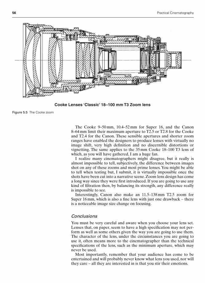
The Cooke 9–50 mm, 10.4–52 mm for Super 16, and the Canon8–64 mm limit their maximum aperture to T2.5 or T2.8 for the Cookeand T2.4 for the Canon. These sensible apertures and shorter zoomranges have enabled the designers to produce lenses with virtually noimage shift, very high definition and no discernible distortions orvignetting. The same applies to the 35 mm Cooke 18–100 T3 lens ofwhich, as you will have gathered, I am a huge fan.
I realize many cinematographers might disagree, but it really isalmost impossible to tell, subjectively, the difference between imagesshot on any of these zooms and most prime lenses. You might be ableto tell when testing but, I submit, it is virtually impossible once theshots have been cut into a narrative scene. Zoom lens design has comea long way since they were first introduced. If you are going to use anykind of filtration then, by balancing its strength, any difference reallyis impossible to see.
Interestingly, Canon also make an 11.5–138 mm T2.5 zoom forSuper 16 mm, which is also a fine lens with just one drawback – thereis a noticeable image size change on focusing.
ConclusionsYou must be very careful and aware when you choose your lens set.Lenses that, on paper, seem to have a high specification may not per-form as well as some others given the way you are going to use them.The character of the lens, under the circumstances you are going touse it, often means more to the cinematographer than the technicalspecifications of the lens, such as the minimum aperture, which maynever be used.
Most importantly, remember that your audience has come to beentertained and will probably never know what lens you used, nor willthey care – all they are interested in is that you stir their emotions.
56 Practical Cinematography
Cooke Lenses ‘Classic’ 18–100 mm T3 Zoom lens
Figure 5.5 The Cooke zoom
Chap-05 2/8/05 11:24 AM Page 56
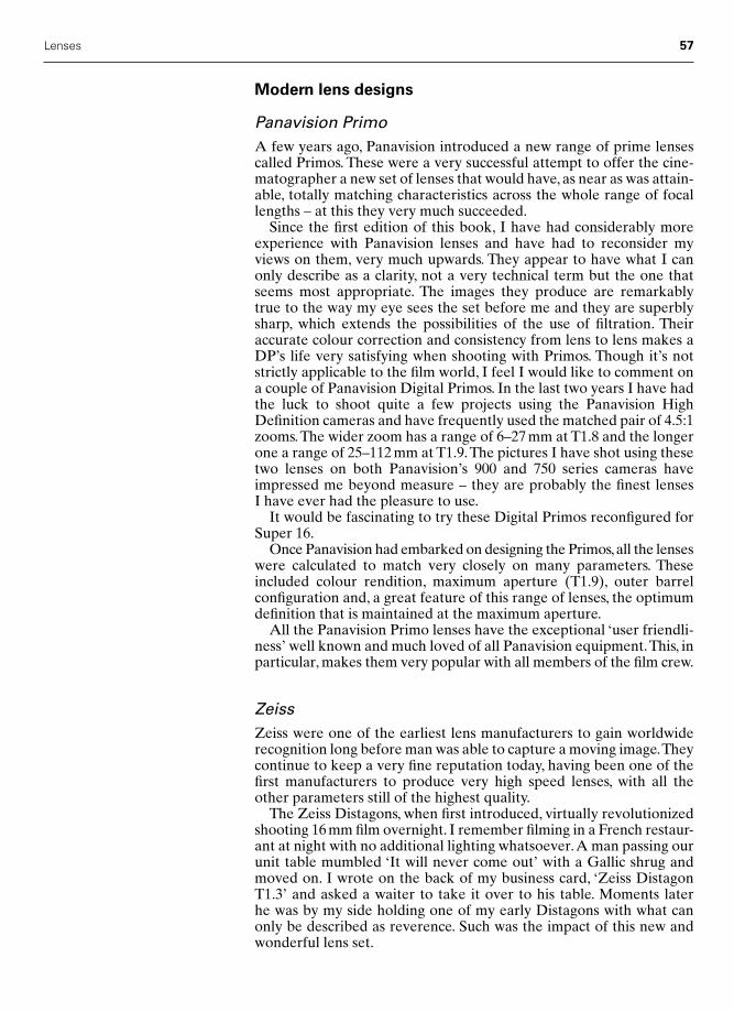
Modern lens designs
Panavision PrimoA few years ago, Panavision introduced a new range of prime lensescalled Primos. These were a very successful attempt to offer the cine-matographer a new set of lenses that would have, as near as was attain-able, totally matching characteristics across the whole range of focallengths – at this they very much succeeded.
Since the first edition of this book, I have had considerably moreexperience with Panavision lenses and have had to reconsider myviews on them, very much upwards. They appear to have what I canonly describe as a clarity, not a very technical term but the one thatseems most appropriate. The images they produce are remarkablytrue to the way my eye sees the set before me and they are superblysharp, which extends the possibilities of the use of filtration. Theiraccurate colour correction and consistency from lens to lens makes aDP’s life very satisfying when shooting with Primos. Though it’s notstrictly applicable to the film world, I feel I would like to comment ona couple of Panavision Digital Primos. In the last two years I have hadthe luck to shoot quite a few projects using the Panavision HighDefinition cameras and have frequently used the matched pair of 4.5:1zooms.The wider zoom has a range of 6–27 mm at T1.8 and the longerone a range of 25–112 mm at T1.9.The pictures I have shot using thesetwo lenses on both Panavision’s 900 and 750 series cameras haveimpressed me beyond measure – they are probably the finest lensesI have ever had the pleasure to use.
It would be fascinating to try these Digital Primos reconfigured forSuper 16.
Once Panavision had embarked on designing the Primos,all the lenseswere calculated to match very closely on many parameters. Theseincluded colour rendition, maximum aperture (T1.9), outer barrelconfiguration and, a great feature of this range of lenses, the optimumdefinition that is maintained at the maximum aperture.
All the Panavision Primo lenses have the exceptional ‘user friendli-ness’ well known and much loved of all Panavision equipment.This, inparticular, makes them very popular with all members of the film crew.
ZeissZeiss were one of the earliest lens manufacturers to gain worldwiderecognition long before man was able to capture a moving image.Theycontinue to keep a very fine reputation today, having been one of thefirst manufacturers to produce very high speed lenses, with all theother parameters still of the highest quality.
The Zeiss Distagons, when first introduced, virtually revolutionizedshooting 16 mm film overnight. I remember filming in a French restaur-ant at night with no additional lighting whatsoever.A man passing ourunit table mumbled ‘It will never come out’ with a Gallic shrug andmoved on. I wrote on the back of my business card, ‘Zeiss DistagonT1.3’ and asked a waiter to take it over to his table. Moments later he was by my side holding one of my early Distagons with what canonly be described as reverence. Such was the impact of this new andwonderful lens set.
Lenses 57
Chap-05 2/8/05 11:24 AM Page 57
The company’s zoom lenses for 16 mm photography are of highquality and have now gone through several generations. I have a par-ticular affection for the original 10–100 mm T3 or T3.1 lens. If you canfind one in good condition it is still a very usable lens much, and wisely,favoured by many film schools.
Zeiss now produce high-speed lenses for both 16 mm and 35 mmphotography, and they are all of the highest quality with some veryinteresting variants, including lenses that can be used for normal photo-graphy but will focus extraordinarily close.
Cooke lenses (S4 range)Soon after the introduction of Panavision’s Primo lenses, which, ofcourse, you could only hire if you were getting your camera equipmentfrom Panavision, a number of independent camera rental houses real-ized that they were slightly wrong-footed as they had nothing to offerwhich might compete with the Primos. The Zeiss super speeds weregood but, by comparison, an older generation of computation. So theygot together and started asking around as to who might producesomething to give them an interesting range to market.
Cooke Lenses had already embarked on the early work of a newrange of prime lenses. Here was a wonderful opportunity. Cooke Lenseshad, for a couple of generations, been revered for very fine lenses with acertain ‘look’. This look is hard to describe and impossible to define inany technical or scientific way. It is an emotional thing: words likeromantic, gentle, deep shadows, kind to the artists all come to mind.Nevertheless, Cooke lenses have always had very good definition.
Cooke have, over the years prior to the introduction of the S4 range,produced three important series of prime lenses. The Series 1 rangewere innovative in their time but now hopelessly out of date. TheirSeries 2 are famed worldwide. Perceived wisdom, which I agree with,says that a set of Series 2 lenses, with the 18 mm replaced by a Series 3lens that is superior to the Series 2, may well have been the ultimateset of prime lenses of that era. I have shot two pictures with exactlythis set (admittedly they had all been recoated and set in new housingsby Century Precision Optics) and received much praise for the results.As a cinematographer, what else does one choose a set of lenses for?Both pictures were, of course, period pieces, where the lenses helpedme create the feeling of the times.
Having now tried the Cooke S4 range, I am very impressed. Some-how they have produced an utterly modern set of lenses but haveretained the ‘Cooke look’.
Cooke have also brought the range very much up to date as regardsthe mechanical engineering. Having taken note of a modern focuspuller’s needs, they have completely dispensed with the conventionalscroll or screw-thread method of racking the lens in and out to focus itand, borrowing design thoughts from their zoom lenses, used cams andcam followers to give a much more linear feel to the focusing scale,together with greater smoothness. This has enabled them to engrave avery user-friendly focus scale, giving focus pullers much greater con-trol over their craft.
For many cinematographers a huge advantage of the Cooke S4primes is that they match to extraordinary close tolerances the colour
58 Practical Cinematography
Chap-05 2/8/05 11:24 AM Page 58

rendition and feel of the Cooke zooms. They are also all optimized towork at their common maximum aperture of T2.
ChoiceSo which range of lenses should you choose? It doesn’t really matter –Ziess, Primos and Cooke S4s are all absolutely superb.What is importantis that you read the script first, decide on the look you want and thenchoose the lens set that suits you best. Today’s cinematographers areextraordinarily lucky to have a choice of at least three great sets of lenses.
Lens distortion and aberrations
The three most common forms of optical distortion that occur in lensesare known as pincushion distortion, barrelling and chromatic aberration.
Prime lenses very rarely show any discernible distortion.The excep-tion might be extreme wide-angle lenses, some of which show a slighttendency to barrel.
The finest zoom lenses will show no discernible distortion even atthe widest end of their range. Unfortunately, many current zoom lenses,mainly those intended for or derived from those originally intendedfor video cameras, still demonstrate considerable distortion. Again,the most common or exaggerated distortion is barrelling at the widerend of the zoom’s focal range. Because the market for video zoomsasks for very high zoom ratios coupled with wide maximum apertures,the manufacturers cannot meet all the parameters of a perfect lens atprices the market will bear.
The manufacturers do their best but, as in all things, you get whatyou pay for and if you are asking for two of the lenses’ attributes to be long zoom range and wide aperture, then almost certainly otherparameters of the design will suffer. In this case, the choice usuallytends towards a design where a noticeable amount of barrelling occursat the wide end and very noticeable image size change shows stronglywhen the focus is changed.
In many applications barrelling and image shifts are not importantdrawbacks, since the kind of images the lenses will be used to recordmask the faults. For news and sport, where the camera is rarelyabsolutely still, any image shift when focusing will not be noticeable.Slight barrelling will only show where there are vertical lines in thescene near the edge of the frame and, again, this does not occur oftenin these applications.
The effect of distortionFigure 5.6 shows a series of shapes in their perfect form. There is a square containing a circle that itself contains another square. Werewe to photograph this shape using a lens that suffered from pincush-ion distortion, then the resultant image would look very much likeFigure 5.7, not at all acceptable.
If the same Figure 5.6 was photographed using a lens suffering frombarrelling, then the image created would appear as shown in Figure 5.8,again unacceptable.
Lenses 59
Figure 5.6 Test shapes for lensdistortion
Figure 5.7 Pincushion distortion
Figure 5.8 Barrel distortion
Chap-05 2/8/05 11:24 AM Page 59
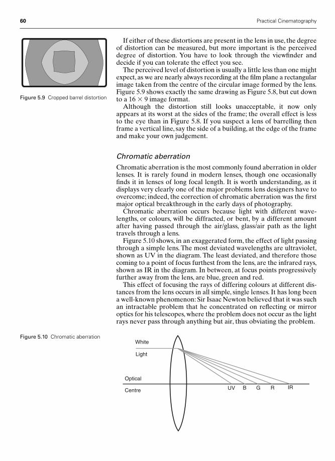
If either of these distortions are present in the lens in use, the degreeof distortion can be measured, but more important is the perceiveddegree of distortion. You have to look through the viewfinder anddecide if you can tolerate the effect you see.
The perceived level of distortion is usually a little less than one mightexpect, as we are nearly always recording at the film plane a rectangularimage taken from the centre of the circular image formed by the lens.Figure 5.9 shows exactly the same drawing as Figure 5.8, but cut downto a 16 � 9 image format.
Although the distortion still looks unacceptable, it now onlyappears at its worst at the sides of the frame; the overall effect is lessto the eye than in Figure 5.8. If you suspect a lens of barrelling thenframe a vertical line, say the side of a building, at the edge of the frameand make your own judgement.
Chromatic aberrationChromatic aberration is the most commonly found aberration in olderlenses. It is rarely found in modern lenses, though one occasionallyfinds it in lenses of long focal length. It is worth understanding, as itdisplays very clearly one of the major problems lens designers have toovercome; indeed, the correction of chromatic aberration was the firstmajor optical breakthrough in the early days of photography.
Chromatic aberration occurs because light with different wave-lengths, or colours, will be diffracted, or bent, by a different amountafter having passed through the air/glass, glass/air path as the lighttravels through a lens.
Figure 5.10 shows, in an exaggerated form, the effect of light passingthrough a simple lens. The most deviated wavelengths are ultraviolet,shown as UV in the diagram. The least deviated, and therefore thosecoming to a point of focus furthest from the lens, are the infrared rays,shown as IR in the diagram. In between, at focus points progressivelyfurther away from the lens, are blue, green and red.
This effect of focusing the rays of differing colours at different dis-tances from the lens occurs in all simple, single lenses. It has long beena well-known phenomenon: Sir Isaac Newton believed that it was suchan intractable problem that he concentrated on reflecting or mirroroptics for his telescopes, where the problem does not occur as the lightrays never pass through anything but air, thus obviating the problem.
60 Practical Cinematography
Figure 5.9 Cropped barrel distortion
UV B G R IR
White
Light
Optical
Centre
Figure 5.10 Chromatic aberration
Chap-05 2/8/05 11:24 AM Page 60
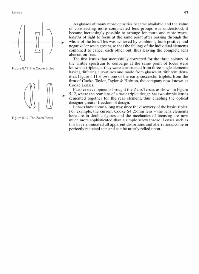
As glasses of many more densities became available and the valueof constructing more complicated lens groups was understood, itbecame increasingly possible to arrange for more and more wave-lengths of light to focus at the same point after passing through thewhole of the lens. This was achieved by combining both positive andnegative lenses in groups, so that the failings of the individual elementscombined to cancel each other out, thus leaving the complete lensaberration-free.
The first lenses that successfully corrected for the three colours ofthe visible spectrum to converge at the same point of focus wereknown as triplets, as they were constructed from three single elementshaving differing curvatures and made from glasses of different dens-ities. Figure 5.11 shows one of the early, successful triplets, from thefirm of Cooke, Taylor, Taylor & Hobson, the company now known asCooke Lenses.
Further developments brought the Zeiss Tessar, as shown in Figure5.12, where the rear lens of a basic triplet design has two simple lensescemented together for the rear element, thus enabling the opticaldesigner greater freedom of design.
Lenses have come a long way since the discovery of the basic triplet.For example, the current Cooke S4 25 mm lens – the lens elementshere are in double figures and the mechanics of focusing are nowmuch more sophisticated than a simple screw thread. Lenses such asthis have eliminated all apparent distortions and aberrations, come inperfectly matched sets and can be utterly relied upon.
Lenses 61
Figure 5.11 The Cooke triplet
Figure 5.12 The Zeiss Tessar
Chap-05 2/8/05 11:24 AM Page 61

6
Film stock
What is film?
Rolls of film are always known as film stock. You will hear unexposedfilm referred to as raw stock. Once it is exposed, but not yet processed,it becomes known as the rushes. Once exposed and processed, it is themaster negative. Confusingly, the print or tape sent back to productionby the laboratory the morning after processing is also known as therushes. In America, these rushes are known as the dailies, which removesthe confusion.
Today’s colour film stocks are fairly complicated affairs, consisting of a support medium, known as the base, which is coated on one sidewith as many as nine layers of light-sensitive emulsions. In addition,there are several other layers such as the yellow filter layer.All of theselayers are collectively known as the emulsion. The top layer of theemulsion is known as the supercoat, whose purpose is both to protectthe film from mechanical damage and to lubricate it through the cam-era gate. On the reverse side of the base, there is a removable coatingcalled the rem-jet backing. This is black and eliminates halation –haloes around bright points of light. It is anti-static and also lubricated.
The history of the negative/positive photographic
process
The knowledge of photosensitive salts was noted by Albertus Magnusas long ago as the thirteenth century. The basis of obtaining an imageusing these salts was much worked upon but not made practical in thesense we know photography today until the mid-nineteenth century.In 1819, Sir John Herschel, the British scientist, discovered sodiumhyposulphate and its ability to dissolve silver chloride. It was not until1839, 20 years later, that he told his friend William Henry Fox Talbotof the discovery. By this time, Fox Talbot had developed a method ofobtaining an image on photosensitive paper using a silver halide as thereactive chemical.The image was a negative one, but he had not founda method of making it permanent, or fixing it. Sodium hyposulphate
62
Chap-06 2/8/05 1:10 PM Page 62

Film stock 63
dissolved out the still sensitive silver halide crystals, leaving stablemetallic silver as the image.
It was not until 31 January 1839 that Fox Talbot was able to presenta paper to the Royal Society in London showing he could make ‘photo-genic drawings’ or shadows of real objects. By the end of September1840, Fox Talbot had discovered the theory of the latent image andfound a method of developing it and stabilizing it, or fixing it, to anacceptable degree of permanence using Herschel’s sodium hyposul-phate. This technique he called the Calotype and this was the origin-ator of today’s negative/positive photographic process. At this stage,though, both the negative and the positive had to be made on papersoaked in the light-sensitive solution.
In the British Journal of Photography of 18 September 1871, anEnglish doctor, Richard L. Maddox, announced his method of spread-ing a warm solution of gelatine onto glass plates, the gelatine beingmixed with cadmium bromide and silver nitrate. Thus, a further steptowards modern photography was taken, for now a light-sensitiveemulsion could be coated on an independent support material.
By around 1883, further developments in emulsion chemistry hadgiven the world an efficient dry photographic plate, made of glass,which could be prepared long in advance of the need to use it, couldbe kept for a considerable time after exposure and before develop-ment, and required less than a second’s exposure in daylight.
By 1889, George Eastman was using a thin film of the plastic cellu-loid as a base material for the film for his latest amateur still cameraand it was the introduction of this support medium, or base, that pro-duced the last factor needed for a film that could be used practically bythe inventors of motion picture equipment.
The early film bases were made of nitrocellulose. This produced avery transparent and flexible support. Unfortunately, the material isalso highly inflammable and somewhat dimensionally unstable. By1920, a ‘safety’ base using cellulose acetate became available that ismore stable, slow to ignite and burned at the same rate as paper. It isthe instability of the nitrate base that is the main reason for the poorsurvival of early films. However, nitrate base continued to be used upto the 1950s, when it was phased out.
From this potted history it is reasonable to say that four crucial elem-ents had to be present before a film stock capable of supporting amoving image was available. They were:
1 The discovery of the latent image and how to develop it.2 The application of a fixer to that developed image to give it
permanence.3 The knowledge of how to incorporate the sensitive chemical in a
supporting medium, gelatine, so that it could easily be coated onan independent base.
4 The introduction of a flexible support for the image, celluloid, sothat the film could run through an intermittent mechanism.
The basic photographic process
In order to consider the basic photographic process, let us look at asimple black and white film whose physical construction will be muchas shown in Figure 6.1.
Chap-06 2/8/05 1:10 PM Page 63
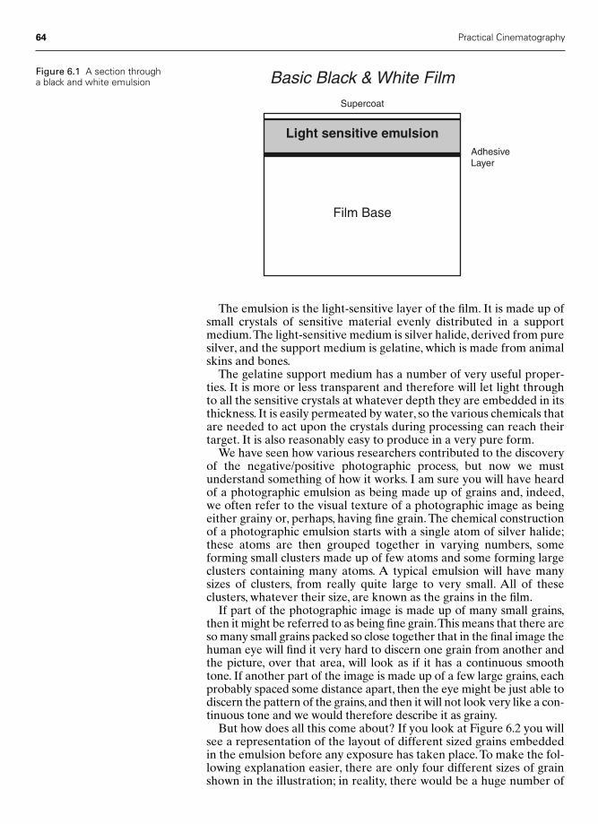
64 Practical Cinematography
The emulsion is the light-sensitive layer of the film. It is made up ofsmall crystals of sensitive material evenly distributed in a supportmedium.The light-sensitive medium is silver halide, derived from puresilver, and the support medium is gelatine, which is made from animalskins and bones.
The gelatine support medium has a number of very useful proper-ties. It is more or less transparent and therefore will let light throughto all the sensitive crystals at whatever depth they are embedded in itsthickness. It is easily permeated by water, so the various chemicals thatare needed to act upon the crystals during processing can reach theirtarget. It is also reasonably easy to produce in a very pure form.
We have seen how various researchers contributed to the discoveryof the negative/positive photographic process, but now we mustunderstand something of how it works. I am sure you will have heardof a photographic emulsion as being made up of grains and, indeed,we often refer to the visual texture of a photographic image as beingeither grainy or, perhaps, having fine grain. The chemical constructionof a photographic emulsion starts with a single atom of silver halide;these atoms are then grouped together in varying numbers, someforming small clusters made up of few atoms and some forming largeclusters containing many atoms. A typical emulsion will have manysizes of clusters, from really quite large to very small. All of these clusters, whatever their size, are known as the grains in the film.
If part of the photographic image is made up of many small grains,then it might be referred to as being fine grain.This means that there areso many small grains packed so close together that in the final image thehuman eye will find it very hard to discern one grain from another andthe picture, over that area, will look as if it has a continuous smoothtone. If another part of the image is made up of a few large grains, eachprobably spaced some distance apart, then the eye might be just able todiscern the pattern of the grains, and then it will not look very like a con-tinuous tone and we would therefore describe it as grainy.
But how does all this come about? If you look at Figure 6.2 you willsee a representation of the layout of different sized grains embeddedin the emulsion before any exposure has taken place. To make the fol-lowing explanation easier, there are only four different sizes of grainshown in the illustration; in reality, there would be a huge number of
AdhesiveLayer
Supercoat
Light sensitive emulsion
Film Base
Basic Black & White FilmFigure 6.1 A section througha black and white emulsion
Chap-06 2/8/05 1:10 PM Page 64

Film stock 65
different sizes of grains. For the propose of understanding moreclearly, let us consider one grain of each of the four sizes in our exam-ple being hit by an even area of light. Light is made up of particles ofenergy we refer to as photons, so if you look at Figure 6.3 you will seeour four different sized grains being attacked by an even array of pho-tons, each represented by an arrow. Because the photons are evenlyspaced and the grains are of differing sizes, the number of photons tohit each grain will differ.
What will happen next is a chemical reaction. We have seen thatbelow the grain size there is a molecular structure. Let us suppose, for
Figure 6.2 The grain field
7
3
4
2
1
Figure 6.3 Photons hittinggrains
Chap-06 2/8/05 1:10 PM Page 65
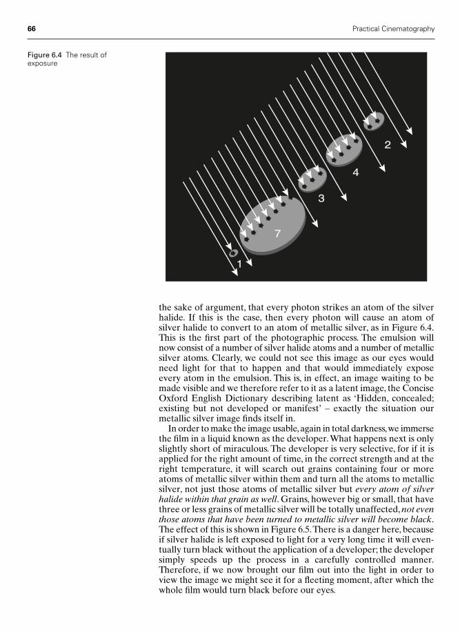
66 Practical Cinematography
the sake of argument, that every photon strikes an atom of the silverhalide. If this is the case, then every photon will cause an atom of silver halide to convert to an atom of metallic silver, as in Figure 6.4.This is the first part of the photographic process. The emulsion willnow consist of a number of silver halide atoms and a number of metallicsilver atoms. Clearly, we could not see this image as our eyes wouldneed light for that to happen and that would immediately exposeevery atom in the emulsion. This is, in effect, an image waiting to bemade visible and we therefore refer to it as a latent image, the ConciseOxford English Dictionary describing latent as ‘Hidden, concealed;existing but not developed or manifest’ – exactly the situation ourmetallic silver image finds itself in.
In order to make the image usable,again in total darkness,we immersethe film in a liquid known as the developer.What happens next is onlyslightly short of miraculous. The developer is very selective, for if it isapplied for the right amount of time, in the correct strength and at theright temperature, it will search out grains containing four or moreatoms of metallic silver within them and turn all the atoms to metallicsilver, not just those atoms of metallic silver but every atom of silverhalide within that grain as well. Grains, however big or small, that havethree or less grains of metallic silver will be totally unaffected, not eventhose atoms that have been turned to metallic silver will become black.The effect of this is shown in Figure 6.5.There is a danger here, becauseif silver halide is left exposed to light for a very long time it will even-tually turn black without the application of a developer; the developersimply speeds up the process in a carefully controlled manner.Therefore, if we now brought our film out into the light in order toview the image we might see it for a fleeting moment, after which thewhole film would turn black before our eyes.
7
3
4
2
1
Figure 6.4 The result ofexposure
Chap-06 2/8/05 1:10 PM Page 66
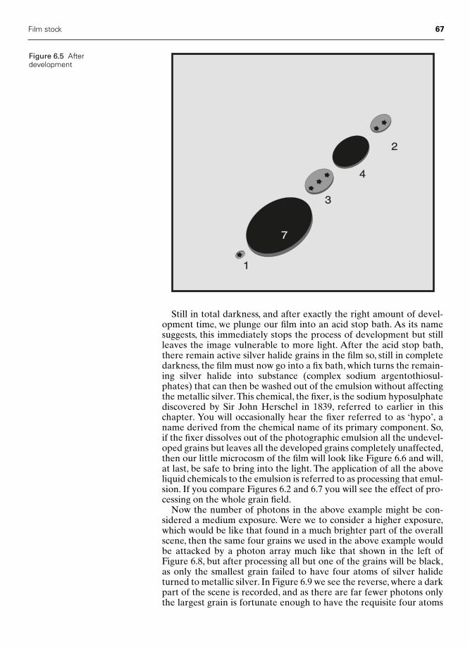
Film stock 67
Still in total darkness, and after exactly the right amount of devel-opment time, we plunge our film into an acid stop bath. As its namesuggests, this immediately stops the process of development but stillleaves the image vulnerable to more light. After the acid stop bath,there remain active silver halide grains in the film so, still in completedarkness, the film must now go into a fix bath, which turns the remain-ing silver halide into substance (complex sodium argentothiosul-phates) that can then be washed out of the emulsion without affectingthe metallic silver.This chemical, the fixer, is the sodium hyposulphatediscovered by Sir John Herschel in 1839, referred to earlier in thischapter. You will occasionally hear the fixer referred to as ‘hypo’, aname derived from the chemical name of its primary component. So,if the fixer dissolves out of the photographic emulsion all the undevel-oped grains but leaves all the developed grains completely unaffected,then our little microcosm of the film will look like Figure 6.6 and will,at last, be safe to bring into the light. The application of all the aboveliquid chemicals to the emulsion is referred to as processing that emul-sion. If you compare Figures 6.2 and 6.7 you will see the effect of pro-cessing on the whole grain field.
Now the number of photons in the above example might be con-sidered a medium exposure. Were we to consider a higher exposure,which would be like that found in a much brighter part of the overallscene, then the same four grains we used in the above example wouldbe attacked by a photon array much like that shown in the left ofFigure 6.8, but after processing all but one of the grains will be black,as only the smallest grain failed to have four atoms of silver halideturned to metallic silver. In Figure 6.9 we see the reverse, where a darkpart of the scene is recorded, and as there are far fewer photons onlythe largest grain is fortunate enough to have the requisite four atoms
Figure 6.5 Afterdevelopment
7
3
4
2
1
Chap-06 2/8/05 1:10 PM Page 67

68 Practical Cinematography
turned from silver halide into metallic silver, resulting, after process-ing, in only a single grain turning to black.
If the film is to remain in perfect condition for many years it mustnow be washed for a considerable time, as all the unwanted chemicalsmust be completely removed and the gelatine emulsion left with onlymetallic silver to form the image.
Therefore, the image formed by this process will have dark areaswhere much light fell upon the film and light areas where little lightarrived and, fortunately for our purpose, all the shades of grey inbetween. It will therefore be the reverse brightness of the originalscene, and this we call a negative image.
In order to obtain an image that represents the original scene, thenegative must be printed on to another piece of film, just as Fox Talbot’sprocess announced in 1839. This new film will produce an image withthe reverse densities of the negative and will return to the values corres-ponding to the original scene. This new film is called the positive andmust be processed in exactly the same way as the camera negative.
Figure 6.6 After fixation
Figure 6.7 Grain field afterprocessing
Chap-06 2/8/05 1:10 PM Page 68

Film stock 69
Colour negative film
There is no such thing as a single colour photographic emulsion.At itssimplest, a modern colour negative film is made up from three blackand white emulsions so arranged that each single layer records theimage of one of the primary colours that make up white light, i.e. red,green and blue.
If you refer to Figure 6.10, you will see how the layers of coatings onthe film base are arranged in order to record a colour image in what isknown as an integral tripack colour emulsion. Under the supercoat isthe first emulsion. It is relatively easy to make a black and white emul-sion that is only sensitive to blue light, so this is used as the uppermostemulsion layer. Underneath this coating is an optical filter layercoloured yellow. A yellow filter will let green and red light through,but not blue. Again, it is possible to make a black and white emulsionthat is only sensitive to green and blue light, but all the blue light hasnow been filtered out, so this layer will only be struck by the green andred light passed by the yellow filter. It will, therefore, only record thegreen part of the image. The bottom emulsion layer is sensitive to redand blue, but not to green, so this layer can only respond to red as bluehas been filtered out.
HighExposure
AfterProcessing
After processing
14
5
9
4
1
Photons hitting grain field
�
Figure 6.8 The effect of high exposure after processing
4
1
2
1
0
LowExposure
AfterProcessing
�
Figure 6.9 The effect of low exposure after processing
Chap-06 2/8/05 1:10 PM Page 69

70 Practical Cinematography
If an exposed film of this type is simply immersed in the standardblack and white developer/fixer process, all you will get is three blackand white images. Therefore, a clever bit of chemistry is incorporatedin each of the three emulsions. The chemicals used are known ascolour couplers. Each individual layer has embedded in it a differentcolour coupler whose job is, at a molecular level, to form a dye of the colour complementary to the colour of the light that exposed thelayer. What is more, this dye is formed only where silver is formed bythe developer.
As this is a negative film intended for printing, each layer of emul-sion must end up dyed the complementary colour to the originalscene. Therefore:
● The blue-sensitive layer forms yellow dye.● The green-sensitive layer forms magenta dye.● The red-sensitive layer forms cyan dye.
Early colour film was capable of recording roughly seven stops oftonal range or a brightness range of 128:1. Modern film stocks havenow been introduced with a tonal range of around 10 stops or a bright-ness range of over 1000:1.
This has been made possible by the development of super-thin emul-sion layers and the concept of coating two or three emulsions to makeup each colour layer. Figure 6.11 shows the basic layout of such a film.The trick is to coat layers of emulsion with different sensitivities, e.g. ahighly sensitive emulsion, a medium sensitivity emulsion and a slowemulsion, together as a triple layer for each colour. By carefully over-lapping the tonal range of each individual emulsion, the film can
Film Base
Supercoat
Yellow filter transmitsGreen and Red
Interlayer
Antihilation Backing
WHITE LIGHT
Blue ONLY sensitive layer
Green & Blue sensitive layer
Red & Blue sensitive layer
BLUE GREEN RED
Figure 6.10 A sectionthrough an integral tripackcolour film
Chap-06 2/8/05 1:10 PM Page 70
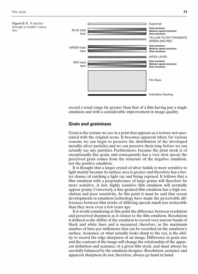
Film stock 71
record a tonal range far greater than that of a film having just a singleemulsion and with a considerable improvement in image quality.
Grain and graininess
Grain is the texture we see in a print that appears as a texture not asso-ciated with the original scene. It becomes apparent when, for variousreasons, we can begin to perceive the distribution of the developedmetallic silver particles and we can perceive them long before we canactually see any particles. Furthermore, because the print stock is ofexceptionally fine grain, and consequently has a very slow speed, theperceived grain comes from the structure of the negative emulsion,not the positive emulsion.
It is thought that a larger crystal of silver halide is more sensitive tolight mainly because its surface area is greater and therefore has a bet-ter chance of catching a light ray and being exposed. It follows that afilm emulsion with a preponderance of large grains will therefore bemore sensitive. A fast, highly sensitive film emulsion will normallyappear grainy. Conversely, a fine-grained film emulsion has a high res-olution and poor sensitivity. At this point it must be said that recentdevelopments in emulsion technology have made the perceivable dif-ferences between film stocks of differing speeds much less noticeablethan they were even a few years ago.
It is worth considering at this point the difference between resolutionand perceived sharpness as it relates to the film emulsion. Resolutionis defined as the ability of the emulsion to record very narrow bands ofblack and white lines and is measured, therefore, as the maximumnumber of lines per millimetre that can be recorded on the emulsion’ssurface. Acutance, or what actually looks sharp to the eye, is the abil-ity to record the edge sharpness of an image. Difference in grain sizeand the contrast of the image will change the relationship of the appar-ent definition and acutance of a given film stock, and must always becarefully balanced by the emulsion designer. Resolution, acutance andapparent sharpness do not, therefore, always go hand in hand.
Film Base
Supercoat
YELLOW FILTER TRANSMITSGREEN AND RED
INTER LAYER
Antihilation Backing
BLUE triplelayer
GREEN triplelayer
RED triplelayer
Fast emulsionMedium speed emulsionSlow emulsion
Fast emulsionMedium speed emulsionSlow emulsion
Fast emulsionMedium speed emulsionSlow emulsion
Figure 6.11 A sectionthrough a modern colourfilm
Chap-06 2/8/05 1:10 PM Page 71

When does grain become unacceptable?
Grain will show up first in two areas of the final image and in bothcases it derives from the metallic silver image created on the negative.
Firstly, it will appear in the continuous mid-tones.Think of a continu-ous blue summer sky photographed using a polarizing filter. Here wehave a continuous, unrelieved density on the print very closely approx-imating a tone close to the middle of the tonal range the film canrecord. If there is the slightest grain or microscopic variation in density,then our audience, whether they be photographically educated or not,will immediately know that this effect is totally unreal, i.e. it doesn’thappen in nature. For this reason their eye will immediately be drawnto this unnatural phenomenon. Secondly, grain becomes very notice-able if it is too apparent in the shadowed part of the final image. Thisis a photographic problem since, on the negative, where dark areas arerepresented by pale areas, there are few exposed silver particles. Thiscontinuous tone is one with only a few exposed grains scattered about.Again, we have a situation where the audience’s awareness demandsthat black is black and not something approximating it with a few bitsof information, the silver crystals, ‘boiling’ in the darkness.
The solution to the mid-tone problem is to choose a film stock with a fine enough grain for the problem never to be apparent to theaudience. The solution to the second problem, grain noticeable in theshadows, is to give the shadows just a little exposure above the bottomthreshold of the film’s recording ability, so that there are just enoughgrains in that area of the negative to deceive the audience’s eye intofailing to see the image of the silver crystals. To discover how to dothis, refer to Chapter 12.
Perforations
Film stock is manufactured in what are known as parent rolls, usually6000 feet long and around a metre and a half wide. The parent rolltherefore needs to be cut, or slit, into the required width of 16, 35, 65or 70 mm. It is usual to slit the whole parent roll into just one filmwidth. Having slit the parent roll into the required width, the film mustthen be perforated. Back at the start of the twentieth century, whenthe motion picture industry was just emerging, one of the main areasof competition between the companies seeking to dominate the mar-ket with their format was the type of perforation used. Edison used arectangular perforation, the French a round one and most otherAmerican companies something approaching a square perforation.Around 1916, the Society of Motion Picture Engineers of Americasought to standardize the perforation used throughout America: theychose to adopt the perforation that had been developed by the Bell &Howell company.This perforation had many advantages. Predominantly,it was strong and, as the dies needed to punch the perforations couldeasily be manufactured to a high degree of accuracy, was consistentlyuniform in both its positioning and size.
Howell had devised his punch by taking a piece of round drill stock0.110 in. in diameter and grinding two parallel flats on it 0.073 in. apart,this becoming the height of the perforation. The resultant shape ofHowell’s perforation can be seen in Figure 6.12.
72 Practical Cinematography
Figure 6.12 Howell’s negativeperforation
Chap-06 2/8/05 1:10 PM Page 72
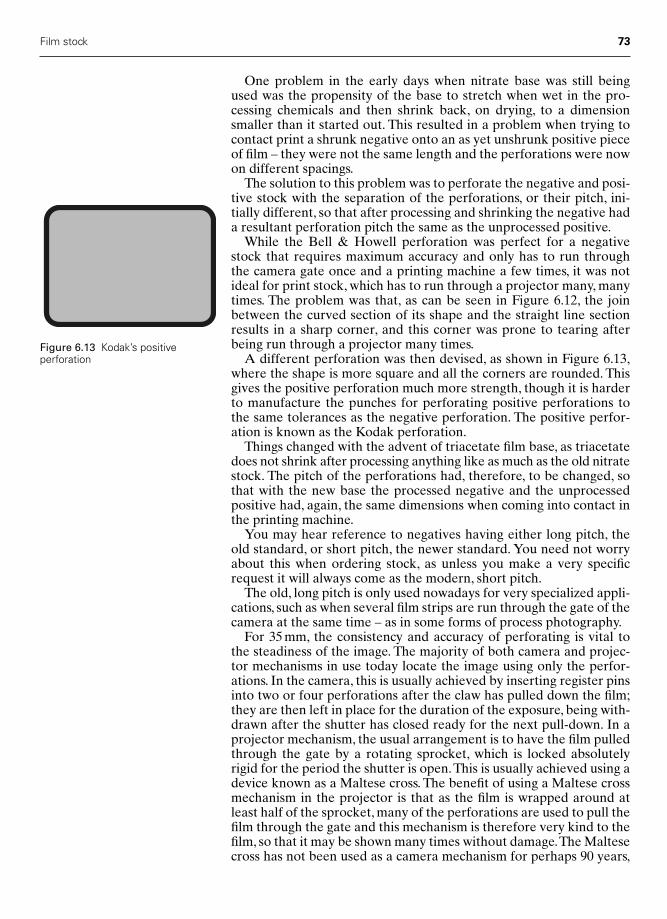
Film stock 73
One problem in the early days when nitrate base was still beingused was the propensity of the base to stretch when wet in the pro-cessing chemicals and then shrink back, on drying, to a dimensionsmaller than it started out. This resulted in a problem when trying tocontact print a shrunk negative onto an as yet unshrunk positive pieceof film – they were not the same length and the perforations were nowon different spacings.
The solution to this problem was to perforate the negative and posi-tive stock with the separation of the perforations, or their pitch, ini-tially different, so that after processing and shrinking the negative hada resultant perforation pitch the same as the unprocessed positive.
While the Bell & Howell perforation was perfect for a negativestock that requires maximum accuracy and only has to run throughthe camera gate once and a printing machine a few times, it was notideal for print stock, which has to run through a projector many, manytimes. The problem was that, as can be seen in Figure 6.12, the joinbetween the curved section of its shape and the straight line sectionresults in a sharp corner, and this corner was prone to tearing afterbeing run through a projector many times.
A different perforation was then devised, as shown in Figure 6.13,where the shape is more square and all the corners are rounded. Thisgives the positive perforation much more strength, though it is harderto manufacture the punches for perforating positive perforations tothe same tolerances as the negative perforation. The positive perfor-ation is known as the Kodak perforation.
Things changed with the advent of triacetate film base, as triacetatedoes not shrink after processing anything like as much as the old nitratestock. The pitch of the perforations had, therefore, to be changed, sothat with the new base the processed negative and the unprocessedpositive had, again, the same dimensions when coming into contact inthe printing machine.
You may hear reference to negatives having either long pitch, theold standard, or short pitch, the newer standard. You need not worryabout this when ordering stock, as unless you make a very specificrequest it will always come as the modern, short pitch.
The old, long pitch is only used nowadays for very specialized appli-cations, such as when several film strips are run through the gate of thecamera at the same time – as in some forms of process photography.
For 35 mm, the consistency and accuracy of perforating is vital tothe steadiness of the image. The majority of both camera and projec-tor mechanisms in use today locate the image using only the perfor-ations. In the camera, this is usually achieved by inserting register pinsinto two or four perforations after the claw has pulled down the film;they are then left in place for the duration of the exposure, being with-drawn after the shutter has closed ready for the next pull-down. In aprojector mechanism, the usual arrangement is to have the film pulledthrough the gate by a rotating sprocket, which is locked absolutelyrigid for the period the shutter is open.This is usually achieved using adevice known as a Maltese cross. The benefit of using a Maltese crossmechanism in the projector is that as the film is wrapped around atleast half of the sprocket, many of the perforations are used to pull thefilm through the gate and this mechanism is therefore very kind to thefilm, so that it may be shown many times without damage.The Maltesecross has not been used as a camera mechanism for perhaps 90 years,
Figure 6.13 Kodak’s positiveperforation
Chap-06 2/8/05 1:10 PM Page 73
74 Practical Cinematography
its disadvantage being that it creates quite a lot of vibration and noise.However, this is no disadvantage in a projection room isolated fromthe audience and where the projector is large and heavy, thus absorb-ing the vibration.
For 16 mm, things are a little different.While some cameras still util-ize a register pin, even they usually only deploy one. Some camerasmanage to give very good registration without a register pin at all.Virtually all cameras, with the exception of the Mitchell and Panaflex16 mm cameras, use edge guides in the film gate to add accuracy to thepositioning of the images on the negative. Some cameras use rigidguides both sides of the film and others use a rigid guide one side witha sprung guide the other to absorb any variation in the slit width of thefilm. This clearly makes the quality of the slitting process more criticalin most 16 mm cameras than their 35 mm counterparts.
Edge numbers
You may have thought of the little numbers printed on the film, betweenthe perforations, as pretty irrelevant – they are not. In fact, to certainparts of our industry, they are the very stuff of life. There are two verydifferent functions carried out by these apparently insignificant numbers.Firstly, there is a number that doesn’t change throughout the roll: thisis the manufacturer’s batch number, which tells you the maker, thetype of film, the emulsion number, the parent roll number and the per-forator number.
All this information becomes vital in the unlikely event of there beinga fault in the manufacture of the stock since, by decoding the batch num-ber, the manufacturer can not only deduce where in their factory thefault lies but, perhaps more importantly, they can immediately contactany other customer who may be about to use the same batch and replacethat batch so as to prevent them shooting on possibly faulty stock.
It is vital that this batch number reaches the laboratory correctlybecause, until the film is developed, the batch number cannot be readas it is applied as a photographic exposure; it is therefore referred toas latent image edge signing. Years ago, some manufacturers mechan-ically printed the batch number on the edge of the film, but this prac-tice is now redundant.
The second number to be printed regularly down the side of the filmdoes not remain the same: it changes every single time it is printed.Again, it is a latent image. This number is there so that when post-production is finished, and the neg. cutters are about to cut the masternegative, it is possible to match this final cut to the negative by usingthese numbers. Kodak, by the way, call their version of these numbersa Key Kode.
If the film has been cut in the traditional manner,by having a rush printmade and physically cutting this print, then the edge numbers on the neg-ative will be printed through onto the print stock together with the image.They can then be read off and a list of cuts made up for the neg. cutter.
By far the most common way of cutting a picture nowadays is usinga non-linear computer editing machine. Here the negative will havebeen directly transferred to videotape and this tape will have beenplayed into the editing computer’s random access memory.At the sametime, the edge numbers, or Key Kode, will have been automatically
Chap-06 2/8/05 1:10 PM Page 74
logged and their relative position will be transferred to a separate partof the computer memory.
This transfer of information is possible because every Key Kode, orits equivalent, is printed onto the negative in two forms: a string ofconventional numbers (referred to as the man-readable numbers) anda bar code (just like those found in the supermarket). These bar codescan easily be read by a scanner as the negative passes through thetelecine during the neg.-to-tape transfer process.These are referred toas the machine-readable numbers.
If the picture has been cut using a non-linear process such as Avidor Lightworks, then at the end of the editing, when a final cut has beenagreed, the computer can be used to produce an edit decision list. Theedit decision list can be transferred to a floppy disk or be printed outas hard copy. From this list it is easy to see, in one column, all the cutsas the edge sign number plus the number of frames to the actual lastframe before the cut. This list is then sent to the neg. cutters to makeup the final cut neg. for printing.
Care, shipping and handling
Although film stock is a fairly robust medium,certain precautions shouldbe taken to keep it in perfect condition, especially before the image hasbeen processed.The main threats to image quality degradation are:
1 Temperature2 Humidity3 Fogging from gases or radiation.
Even when kept in perfect storage conditions, it is advisable to use thefilm within six months of purchase. If you are travelling abroad it isworth remembering that most stock manufacturers offer a service ofpayment in your home country and collection from their nearest agentto your location. In this way, you are at least assured that no deteri-oration by any means has occurred before you start shooting.
Figure 6.14 shows the ranges of both temperature and humidity thatmost manufacturers recommend for storing motion picture film.
The actual speed of the film will have an effect on the rate of or sus-ceptibility to various kinds of damage.This is particularly true of X-rayradiation, where the more sensitive the film is to visible light, the moresensitive it will be to X-rays.
When shipping undeveloped film stock, great care must be exercisedto reduce the amount of X-ray radiation the stock is subjected to.
If you have to travel with your film stock always take it in hand bag-gage. Checked baggage that goes in the hold may receive far more radi-ation than hand baggage and film can be completely ruined. Take withyou a changing bag and a spare, empty, film tin, together with a film bag.With luck you may be able to persuade the check-in personnel to do ahand-search of your film. This is far safer than letting it go through anyX-ray machine, even if they are labelled ‘Film Safe’. For our purposes itis best to assume there is no such thing as a film-safe X-ray machine.
It is often possible to ring the customs department in advance andwarn them of your problem and ask for their co-operation when youget to the barrier.
Film stock 75
Chap-06 2/8/05 1:10 PM Page 75
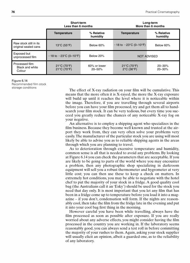
76 Practical Cinematography
The effect of X-ray radiation on your film will be cumulative. Thismeans that the more often it is X-rayed, the more the X-ray exposurewill build up until it reaches the level where it is noticeable within the image. Therefore, if you are travelling through several airportsbefore you can have your film processed, try and get them all to hand-search your film stock. It can be very tedious, but every time you suc-ceed you greatly reduce the chances of any noticeable X-ray fog onyour negative.
An alternative is to employ a shipping agent who specializes in thefilm business. Because they become well known and trusted at the air-port they work from, they can very often solve your problems veryeasily.The manufacturer of the particular stock you are using will mostlikely be able to advise you as to reliable shipping agents in the areasthrough which you are planning to travel.
As to deterioration through excessive temperature and humidity,common sense is all that is needed to avoid any problems. By lookingat Figure 6.14 you can check the parameters that are acceptable. If youare likely to be going to parts of the world where you may encountera problem, then any photographic shop specializing in darkroomequipment will sell you a robust thermometer and hygrometer at verylittle cost; you can then use these to keep a check on matters. Inextremely hot conditions, you may be able to negotiate with the hotelchef to put the majority of your stock in a fridge. A good quality coolbag (the Australians call it an ‘Esky’) should be used for the stock youneed that day only. It is most important that you let any film that hasbeen in a fridge come up to temperature before you load it into a mag-azine – if you don’t, condensation will form. If the nights are reason-ably cool, then take the film from the fridge late in the evening and putit into your cool bag first thing in the morning.
However careful you have been while travelling, always have thefilm processed as soon as possible after exposure. If you are reallyworried about any adverse effects, you might consider having the filmprocessed in the country you are working in. If the laboratory seemsreasonably good, you can always send a test roll in before committingthe majority of your rushes to them. Again, asking your stock supplierwill usually elicit an opinion, albeit a guarded one, as to the reliabilityof any laboratory.
Figure 6.14Recommended film stockstorage conditions
Short-term Long-termLess than 6 months More than 6 months
Temperature % Relative Temperature % Relative humidity humidity
Raw stock still in its13°C (55°F) Below 60% �18 to �23°C (0–10°F) Below 60%original sealed cans
Exposed but �18 to �23°C (0–10°F) Below 20% NOT ADVISEDunprocessed film
Processed film:Black and white 21°C (70°F) 60% or lower 21°C (70°F) 20–30%
Colour 21°C (70°F) 20–50% 2°C (36°F) 20–30%
Chap-06 2/8/05 1:10 PM Page 76
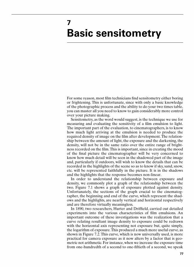
7
Basic sensitometry
For some reason, most film technicians find sensitometry either boringor frightening. This is unfortunate, since with only a basic knowledgeof the photographic process and the ability to do your two times table,you can master all you need to know to gain considerably more controlover your picture making.
Sensitometry, as the word would suggest, is the technique we use formeasuring and evaluating the sensitivity of a film emulsion to light.The important part of the evaluation, to cinematographers, is to knowhow much light arriving at the emulsion is needed to produce therequired density of image on the film after development.The relation-ship between the amount of light, the exposure and the darkening, thedensity, will not be in the same ratio over the entire range of bright-ness recorded on the film.This is important, since in creating the moodof the final picture the cinematographer will be very concerned toknow how much detail will be seen in the shadowed part of the imageand, particularly if outdoors, will wish to know the details that can berecorded in the highlights of the scene so as to know if sky, sand, snow,etc. will be represented faithfully in the picture. It is in the shadowsand the highlights that the response becomes non-linear.
In order to understand the relationship between exposure anddensity, we commonly plot a graph of the relationship between thetwo. Figure 7.1 shows a graph of exposure plotted against density.Unfortunately, the sections of the graph crucial to the cinematog-rapher, the beginning and end of the curve, which represent the shad-ows and the highlights, are nearly vertical and horizontal respectivelyand are therefore virtually meaningless.
In 1890, two researchers, Hurter and Driffield, carried out detailedexperiments into the various characteristics of film emulsions. Animportant outcome of these investigations was the realization that acurve relating resultant image density to exposure could be redrawnwith the horizontal axis representing not exposure but, quite simply,the logarithm of exposure.This produced a much more useful curve, asshown in Figure 7.2. This curve, which is now universally used, is morepractical for camera exposure as it now alters by a factor that is geo-metric not arithmetic. For instance, when we increase the exposure timefrom one-hundredth of a second to one-fiftieth of a second, we speak
77
Chap-07 12/16/04 3:08 PM Page 77
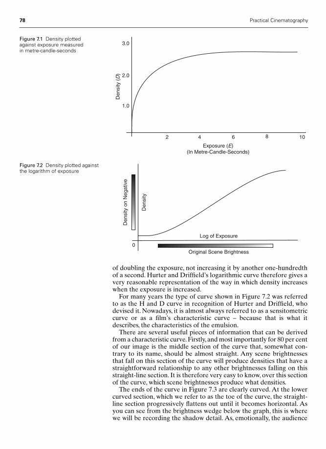
78 Practical Cinematography
of doubling the exposure, not increasing it by another one-hundredthof a second. Hurter and Driffield’s logarithmic curve therefore gives avery reasonable representation of the way in which density increaseswhen the exposure is increased.
For many years the type of curve shown in Figure 7.2 was referredto as the H and D curve in recognition of Hurter and Driffield, whodevised it. Nowadays, it is almost always referred to as a sensitometriccurve or as a film’s characteristic curve – because that is what itdescribes, the characteristics of the emulsion.
There are several useful pieces of information that can be derivedfrom a characteristic curve. Firstly, and most importantly for 80 per centof our image is the middle section of the curve that, somewhat con-trary to its name, should be almost straight. Any scene brightnessesthat fall on this section of the curve will produce densities that have astraightforward relationship to any other brightnesses falling on thisstraight-line section. It is therefore very easy to know, over this sectionof the curve, which scene brightnesses produce what densities.
The ends of the curve in Figure 7.3 are clearly curved. At the lowercurved section, which we refer to as the toe of the curve, the straight-line section progressively flattens out until it becomes horizontal. Asyou can see from the brightness wedge below the graph, this is wherewe will be recording the shadow detail. As, emotionally, the audience
1.0
2.0
3.0
Den
sity
(D
)
Exposure (E)(In Metre-Candle-Seconds)
2 4 6 8 10D
ensi
ty
Log of Exposure
0Original Scene Brightness
Den
sity
on
Neg
ativ
e
Figure 7.1 Density plottedagainst exposure measuredin metre-candle-seconds
Figure 7.2 Density plotted againstthe logarithm of exposure
Chap-07 12/16/04 3:08 PM Page 78
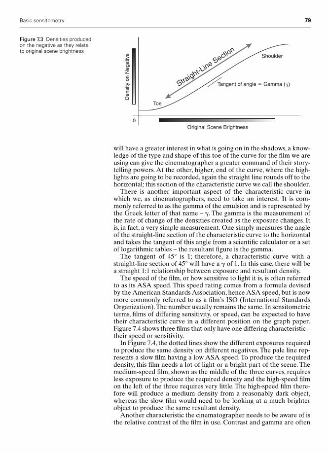
Basic sensitometry 79
will have a greater interest in what is going on in the shadows, a know-ledge of the type and shape of this toe of the curve for the film we areusing can give the cinematographer a greater command of their story-telling powers. At the other, higher, end of the curve, where the high-lights are going to be recorded, again the straight line rounds off to thehorizontal; this section of the characteristic curve we call the shoulder.
There is another important aspect of the characteristic curve inwhich we, as cinematographers, need to take an interest. It is com-monly referred to as the gamma of the emulsion and is represented bythe Greek letter of that name – �. The gamma is the measurement ofthe rate of change of the densities created as the exposure changes. Itis, in fact, a very simple measurement. One simply measures the angleof the straight-line section of the characteristic curve to the horizontaland takes the tangent of this angle from a scientific calculator or a setof logarithmic tables – the resultant figure is the gamma.
The tangent of 45° is 1; therefore, a characteristic curve with astraight-line section of 45° will have a � of 1. In this case, there will bea straight 1:1 relationship between exposure and resultant density.
The speed of the film, or how sensitive to light it is, is often referredto as its ASA speed. This speed rating comes from a formula devisedby the American Standards Association, hence ASA speed, but is nowmore commonly referred to as a film’s ISO (International StandardsOrganization).The number usually remains the same. In sensitometricterms, films of differing sensitivity, or speed, can be expected to havetheir characteristic curve in a different position on the graph paper.Figure 7.4 shows three films that only have one differing characteristic –their speed or sensitivity.
In Figure 7.4, the dotted lines show the different exposures requiredto produce the same density on different negatives. The pale line rep-resents a slow film having a low ASA speed. To produce the requireddensity, this film needs a lot of light or a bright part of the scene. Themedium-speed film, shown as the middle of the three curves, requiresless exposure to produce the required density and the high-speed filmon the left of the three requires very little. The high-speed film there-fore will produce a medium density from a reasonably dark object,whereas the slow film would need to be looking at a much brighterobject to produce the same resultant density.
Another characteristic the cinematographer needs to be aware of isthe relative contrast of the film in use. Contrast and gamma are often
0
Shoulder
Toe
Straight-L
ine Section
Original Scene BrightnessD
ensi
ty o
n N
egat
ive
Tangent of angle � Gamma (�)
Figure 7.3 Densities producedon the negative as they relateto original scene brightness
Chap-07 12/16/04 3:08 PM Page 79

80 Practical Cinematography
confused. As we have seen, gamma is a measurement of the rate ofchange of the exposure–density relationship. Contrast refers to thebrightness range and the gradation between the highlights and theshadows; it is therefore expressed as a ratio. For instance, a televisionpicture, even on a perfectly set-up screen, will only be able to show abrightness range equivalent to five stops of exposure; it will thereforehave a contrast range of 32 : 1, as shown in Figure 7.5. The contrastrange that can be shown on a first-class cinema screen is the equiva-lent of seven stops of exposure. Recently, developments in the con-struction of camera negative emulsions have made it possible tomanufacture a negative able to record the equivalent of 10 stops ofbrightness; this gives the film a contrast ratio of an incredible 1024 : 1.The value of this range to the working cinematographer is discussed inChapter 11.
Despite the definitions above, we still think of a ‘contrasty’ film asone having severe blacks and whites with little information in the mid-tones. This kind of image would probably be described in sensitomet-ric terms as having a high gamma, i.e. one having a steep straight-linesection, as shown in Figure 7.6. It would, in all probability, have a low
Exposure
Den
sity
High Speed FilmMedium Speed FilmLow Speed Film
Figure 7.4 D–log E curveshowing the effect of changingthe speed of the emulsion
For TelevisionBlack Contrast Ratio � 0
�1 Stop Contrast Ratio � 2 : 1�2 Stops Contrast Ratio � 4 : 1�3 Stops Contrast Ratio � 8 : 1�4 Stops Contrast Ratio � 16 : 1�5 Stops Contrast Ratio � 32 : 1
For the Cinema Screen�6 Stops Contrast Ratio � 64 : 1�7 Stops Contrast Ratio � 128 : 1
Modern Extended Latitude Negative�8 Stops Contrast Ratio � 256 : 1�9 Stops Contrast Ratio � 512 : 1
�10 Stops Contrast Ratio � 1024 : 1�11 Stops Contrast Ratio � 2048 : 1
Figure 7.5 Contrast ratiosfor various delivery systems
Chap-07 12/16/04 3:08 PM Page 80

Basic sensitometry 81
contrast ratio. As can be seen by comparing the curves in Figure 7.6,by increasing the gamma and steepening the curve the usable straight-line section relates to a shorter distance along the exposure axis, thusthe contrast ratio will be lower. We must learn to recognize the differ-ence between contrast expressed as a ratio and apparent contrast as a‘soot and whitewash’ image.
In all the graphs shown in this chapter you will see that the curvenever reaches zero on the vertical density line. This is because the filmcan never be made absolutely clear, i.e. having a density of zero.This ismainly the result of two things:
1 The base material it is coated on is not completely clear.2 When film is manufactured it receives an almost imperceptible
exposure from things other than light. The film emulsion is veryslightly sensitive to pressure, heat, etc. and therefore the actualprocess of manufacture causes a very slight darkening.
The resultant small density at the very bottom of the curve we there-fore call the base level fog.
Log of Exposure
Den
sity
Film with a high Gamma
Film with a medium Gamma
Film with a low Gamma
Figure 7.6 The effect ofchanging the gamma of anemulsion
Chap-07 12/16/04 3:08 PM Page 81

8
The laboratory
The laboratory contact
The laboratory contact person (always referred to as the ‘lab contact’)is one of the more important people in a DP’s life. Every morning,usually somewhere between 7.30 and 8.00, a member of the cameracrew will be detailed to phone the lab. This is to obtain the report onyesterday’s rushes, or dailies as they are known in the USA.The reportwill contain information as to how well the contact thought the over-all look of the rushes had been achieved, an accurate list of any hairsor scratches with precise slate numbers and the all-important printerlights. The printer lights are usually given in the order of red, greenand blue with, often, an average of all three colours for each scene orroll. This is known as an overall light and is an expression of the over-all exposure.
The overall exposure figure will only be of use if you have beenworking under normal lighting conditions. If you have been shiftingyour colours using the grey scale or, for instance, shooting under fluo-rescent lighting, you will need to interpret the RGB (Red, Green,Blue) numbers.
Your laboratory contact will have been responsible for setting thegrading lights the night before and can therefore have a huge effect onthe look of the DP’s work. For this reason, it is always wise to talk tothe lab contact before starting a picture; this way they know what youare trying to achieve. For the same reason, I always try and make thatearly morning call myself, not just to get a feel for yesterday’s workbut to discuss what we are going to be shooting today, so the contacthas some idea of what I had in mind when they come to grade the neg-ative in the small hours of the morning.
If you are working on one set for several days, it is a good idea toinvite the lab contact on to the set. They spend so much of their life inthe dark they are usually only too grateful for the chance of a visit.More importantly, it lets them see the real thing and this makes theirinvolvement in the production all the more real.
82
Chap-08 12/16/04 3:09 PM Page 82

The laboratory 83
Printer lights
The printer lights quoted by the lab are derived from the first printingmachine that had a truly successful light source with which to controla mixture of red, green and blue lights within very fine degrees. Thiswas, and is, the Bell & Howell Model C printer.
Figure 8.1 shows a schematic diagram of the Model C’s light source.White light from a simple tungsten source is first put through a con-denser lens so as to form an organized beam. The beam of light thenarrives at a diachroic mirror, which will reflect red light but is transpar-ent to green and blue light. The beam continues until it reaches thesecond mirror, which will only reflect green light and is transparent toblue light. The beam continues further to the last mirror, which willonly reflect blue light.
All of the individual beams, one each for these three colours, nowpass through their own, separate iris. Each iris is identical and has 50carefully graduated settings, where the difference between all the set-tings is usually equivalent to one-sixth of a stop on a camera lens.
Using simple mirrors, and a second condenser lens, all the threecolours are then recombined into a homogeneous light source. Thislight source then delivers its beam to the printer gate.
If all three irises controlling the individual primary colours were setto their middle position, light 25 on the scale, then pure white lightwould be delivered to the printer’s gate. Things are so arranged thatthis would also, normally, be the perfect exposure for a perfectlyexposed negative being printed onto a standard print stock.We wouldthen know that if the laboratory reported RGB printer lights of25,25,25, our negative was perfectly exposed and had printed most satisfactorily.
Diachroic Mirrors Reflecting:
RED GREEN BLUE
Individual Irisesfor Each Light Path
Plain Mirrors
Printer Gate
Plain Mirrors
TungstenLight Source
Condenser Lens
CondenserLens
HomogenousMixedLightOutput
Figure 8.1 Schematic diagramof the Bell & Howell Model Cprinter light source
Chap-08 12/16/04 3:09 PM Page 83
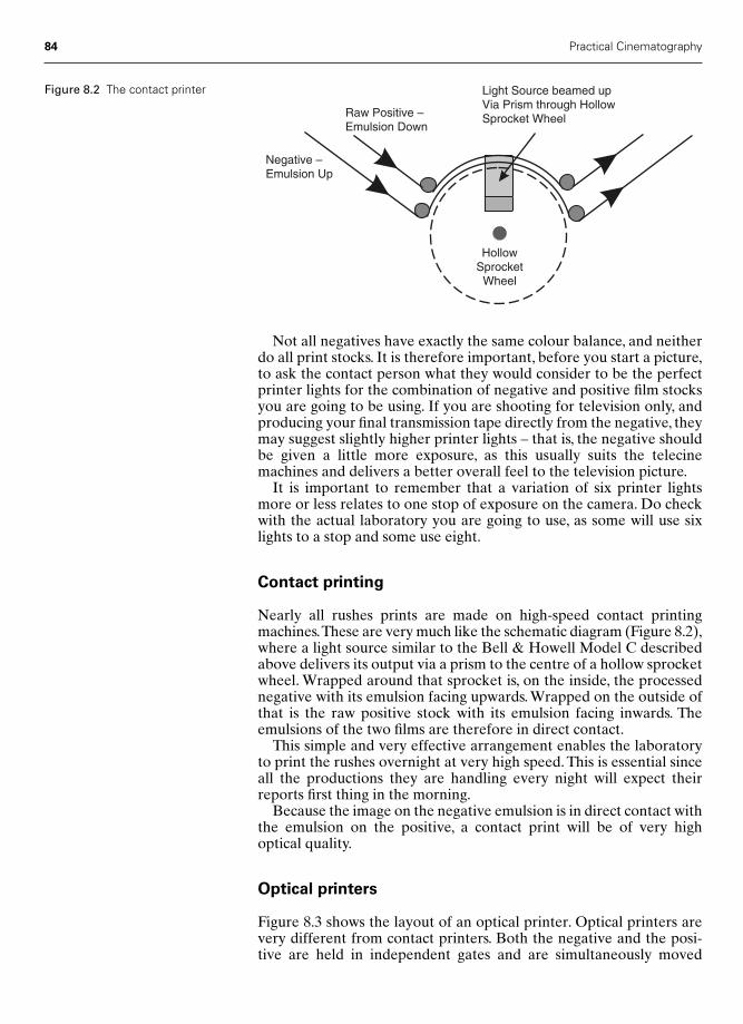
84 Practical Cinematography
Not all negatives have exactly the same colour balance, and neitherdo all print stocks. It is therefore important, before you start a picture,to ask the contact person what they would consider to be the perfectprinter lights for the combination of negative and positive film stocksyou are going to be using. If you are shooting for television only, andproducing your final transmission tape directly from the negative, theymay suggest slightly higher printer lights – that is, the negative shouldbe given a little more exposure, as this usually suits the telecinemachines and delivers a better overall feel to the television picture.
It is important to remember that a variation of six printer lightsmore or less relates to one stop of exposure on the camera. Do checkwith the actual laboratory you are going to use, as some will use sixlights to a stop and some use eight.
Contact printing
Nearly all rushes prints are made on high-speed contact printingmachines.These are very much like the schematic diagram (Figure 8.2),where a light source similar to the Bell & Howell Model C describedabove delivers its output via a prism to the centre of a hollow sprocketwheel. Wrapped around that sprocket is, on the inside, the processednegative with its emulsion facing upwards. Wrapped on the outside ofthat is the raw positive stock with its emulsion facing inwards. Theemulsions of the two films are therefore in direct contact.
This simple and very effective arrangement enables the laboratoryto print the rushes overnight at very high speed. This is essential sinceall the productions they are handling every night will expect theirreports first thing in the morning.
Because the image on the negative emulsion is in direct contact withthe emulsion on the positive, a contact print will be of very high optical quality.
Optical printers
Figure 8.3 shows the layout of an optical printer. Optical printers arevery different from contact printers. Both the negative and the posi-tive are held in independent gates and are simultaneously moved
Negative –Emulsion Up
Raw Positive –Emulsion Down
Light Source beamed upVia Prism through HollowSprocket Wheel
HollowSprocketWheel
Figure 8.2 The contact printer
Chap-08 12/16/04 3:09 PM Page 84
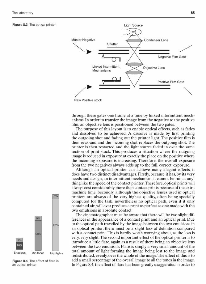
The laboratory 85
through these gates one frame at a time by linked intermittent mech-anisms. In order to transfer the image from the negative to the positivefilm, an objective lens is positioned between the two gates.
The purpose of this layout is to enable optical effects, such as fadesand dissolves, to be achieved. A dissolve is made by first printing the outgoing shot and fading out the printer light. The positive film isthen rewound and the incoming shot replaces the outgoing shot. Theprinter is then restarted and the light source faded in over the samesection of print stock. This produces a situation where the outgoingimage is reduced in exposure at exactly the place on the positive wherethe incoming exposure is increasing. Therefore, the overall exposurefrom the two negatives always adds up to the full, correct, exposure.
Although an optical printer can achieve many elegant effects, itdoes have two distinct disadvantages. Firstly, because it has, by its veryneeds and design, an intermittent mechanism, it cannot be run at any-thing like the speed of the contact printer.Therefore, optical prints willalways cost considerably more than contact prints because of the extramachine time. Secondly, although the objective lenses used in opticalprinters are always of the very highest quality, often being speciallycomputed for the task, nevertheless no optical path, even if it onlycontained air, will ever produce a print as perfect as one made with thetwo emulsions in absolute contact.
The cinematographer must be aware that there will be two slight dif-ferences in the appearance of a contact print and an optical print. Dueto the optical path travelled by the image between the two emulsions inan optical printer, there must be a slight loss of definition comparedwith a contact print. This is hardly worth worrying about, as the loss isvery, very slight. The second important effect of the optical printer is tointroduce a little flare, again as a result of there being an objective lensbetween the two emulsions. Flare is simply a very small amount of thetotal amount of light forming the image being lost to the image andredistributed, evenly, over the whole of the image.The effect of this is toadd a small percentage of the overall image to all the tones in the image.In Figure 8.4, the effect of flare has been greatly exaggerated in order to
Light Source
Condenser Lens
Negative Film Gate
Positive Film Gate
Objective Lens
Master Negative
Raw Positive stock
Linked IntermittentMechanisms
Shutter
Figure 8.3 The optical printer
Shadows
10%
5%
Mid-tones
50%
5%
Highlights
90%
5%
Figure 8.4 The effect of flare inan optical printer
Chap-08 12/16/04 3:09 PM Page 85
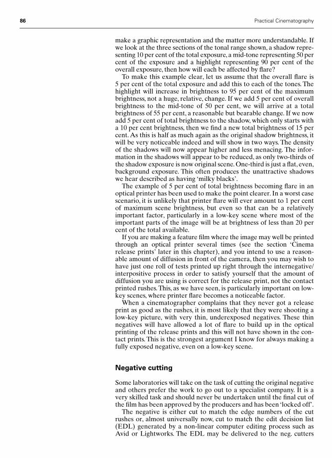
86 Practical Cinematography
make a graphic representation and the matter more understandable. Ifwe look at the three sections of the tonal range shown, a shadow repre-senting 10 per cent of the total exposure, a mid-tone representing 50 percent of the exposure and a highlight representing 90 per cent of theoverall exposure, then how will each be affected by flare?
To make this example clear, let us assume that the overall flare is 5 per cent of the total exposure and add this to each of the tones. Thehighlight will increase in brightness to 95 per cent of the maximumbrightness, not a huge, relative, change. If we add 5 per cent of overallbrightness to the mid-tone of 50 per cent, we will arrive at a totalbrightness of 55 per cent, a reasonable but bearable change. If we nowadd 5 per cent of total brightness to the shadow, which only starts witha 10 per cent brightness, then we find a new total brightness of 15 percent. As this is half as much again as the original shadow brightness, itwill be very noticeable indeed and will show in two ways. The densityof the shadows will now appear higher and less menacing. The infor-mation in the shadows will appear to be reduced, as only two-thirds ofthe shadow exposure is now original scene. One-third is just a flat, even,background exposure. This often produces the unattractive shadowswe hear described as having ‘milky blacks’.
The example of 5 per cent of total brightness becoming flare in anoptical printer has been used to make the point clearer. In a worst casescenario, it is unlikely that printer flare will ever amount to 1 per centof maximum scene brightness, but even so that can be a relativelyimportant factor, particularly in a low-key scene where most of theimportant parts of the image will be at brightness of less than 20 percent of the total available.
If you are making a feature film where the image may well be printedthrough an optical printer several times (see the section ‘Cinemarelease prints’ later in this chapter), and you intend to use a reason-able amount of diffusion in front of the camera, then you may wish tohave just one roll of tests printed up right through the internegative/interpositive process in order to satisfy yourself that the amount ofdiffusion you are using is correct for the release print, not the contactprinted rushes. This, as we have seen, is particularly important on low-key scenes, where printer flare becomes a noticeable factor.
When a cinematographer complains that they never got a releaseprint as good as the rushes, it is most likely that they were shooting alow-key picture, with very thin, underexposed negatives. These thinnegatives will have allowed a lot of flare to build up in the opticalprinting of the release prints and this will not have shown in the con-tact prints. This is the strongest argument I know for always making afully exposed negative, even on a low-key scene.
Negative cutting
Some laboratories will take on the task of cutting the original negativeand others prefer the work to go out to a specialist company. It is avery skilled task and should never be undertaken until the final cut ofthe film has been approved by the producers and has been ‘locked off’.
The negative is either cut to match the edge numbers of the cutrushes or, almost universally now, cut to match the edit decision list(EDL) generated by a non-linear computer editing process such asAvid or Lightworks. The EDL may be delivered to the neg. cutters
Chap-08 12/16/04 3:09 PM Page 86

The laboratory 87
on a paper printout or a computer floppy disk, or perhaps both forsafety.
If a print is required then the negative will be cut in the formatknown as an A and B roll. The principal of A and B roll neg. cutting isthat you put all the odd shot numbers on one roll of film with blackspacing between each shot.You then make up another roll of film withall the even numbered shots on it, again with black spacing in between.On both rolls you make the spacing the same length as the missingshot, which is on the other roll.
You can vary this technique to let two shots overlap, so that a dis-solve can be created when the two rolls are printed one after the other.
Figure 8.5 shows how the A and B rolls might be laid out. The firstshot of the film is on the top roll, roll A.This roll is printed to the posi-tive first. When the shot comes to an end, black spacing is cut on andthus there will be no exposure on the positive.
When the second roll is printed to the positive there will be noexposure from it during shot 1, as it only consists of black spacing. Atexactly the frame where the exposure from roll A ends, the exposurefrom roll B will start. In this way, one gets a continuous, single lengthof film with all the cuts printed onto it.
The sequence continues as scene 3, being an odd-numbered scene,gets printed at exactly the point where scene 2 on roll B ends. At theend of scene 3, the editor has decided to have a dissolve to scene 4.Thescenes have therefore to overlap; scene 3 continues longer on roll Abefore being cut to black. The incoming scene, scene 4, must startexactly the same amount earlier. When printing scene 3 from roll Athe printer will fade to black for, say, 20 frames. If a 20-frame dissolvehas been decided upon, then scene 4 on roll B will start 20 frames earlyand, when printed, will fade in to full exposure for those 20 frames andremain at full exposure until the end of that shot.
The cut negative will therefore consist of two rolls of identicallength. Roll A will contain all the odd-numbered shots and roll B allthe even-numbered shots. Where no exposure is required from one ofthe rolls there will be black spacing. When both rolls have beenprinted, one after the other, the result will be the whole film on a sin-gle roll with no physical joins.
Cinema release prints
Making cinema release prints is a somewhat protracted business,made so by the need for many release prints, possibly in the hundreds
ROLL AScene 1Continuous sceneCut at end toRoll B
ROLL BBlack SpacingSo as to makeno Exposureon Print
ROLL ABlackSpacing
ROLL BCut toScene 2
ROLL B – BlackSpacing
ROLL AScene 3 – Fades out at endof overlap with other roll
ROLL BScene 4 – Fades in abeginning of scene
ROLL AReturns to blackspacingat end of overlap
ROLL BCuts toBlackSpacing
ROLL ACuts toScene 5
Figure 8.5 A and B roll negativecutting
Chap-08 12/16/04 3:09 PM Page 87

88 Practical Cinematography
for worldwide distribution, all of which must originate from the singlecamera negative. Even if one were prepared to try and print all therelease prints from the camera negative, it would simply not bemechanically strong enough to make that many prints.
What is needed therefore are a number of duplicate negatives, ofvery high quality, from each of which a sensible number of prints canbe made, or ‘struck’ as the process is often referred to.
The process starts with the A and B roll cut negative. This will begraded and a trial print will be struck; this is known as the first answerprint. It may take several answer prints before the director, the DP, theproducer and the laboratory are all happy with the finished result.When they are happy a fine grain, graded, interpositive will be struck.From the interpositive, an internegative will be struck and a printmade from this and checked by all concerned.This process is shown inFigure 8.6.
If the test print from the first internegative is considered to be allthat is expected, then further internegatives will be made. From eachof these internegatives many release prints can be struck.
It is in everyone’s interest that the camera negative, now cut as A and B rolls, must be run through a printer as rarely as possible, for itnow represents the whole of the producer’s investment.There is muchrelief when a successful internegative has been struck, since only then,for the first time, is there an alternative to the master camera negativeshould something unfortunate happen to that master.
On very big budget pictures, when all the required internegativeshave been approved and, perhaps, a safety copy of the original inter-positive has been made, a single print may be struck from the cameraoriginal A and B roll cut negatives. This is known as the premier copyand will be used for the one-off showings at international premieres.As we have seen in the earlier part of this chapter, there is a slight lossof quality as the image goes through the various prints and negativesthat come between the camera negative and a normal release print. Inorder to make the premiere showing as special as possible, these pre-miere prints will occasionally be struck.
The ‘long-handled’ negative cut
When shooting film destined only for television transmission, manypeople believe the finest quality is achieved by directly transferringthe camera negative to a digital master tape. If the negative has beenexposed with this in mind, I am a great advocate of this process.
Providing a print is never going to be required, then the A and B rollneg. cut can be a hindrance rather than an asset. In order to transfer anA and B roll cut, each roll must go through a telecine machine on itsown, which produces two master tapes that are automatically, usingthe EDL, conformed into a single master tape. The disadvantage isthat it is very difficult to grade the film when you cannot see the shotsone after another.
If both a print and a neg. transfer are required, a compromise is usu-ally to grade the A and B rolls as best you can,conform the tape and havea final grading session from tape to tape.This has a huge disadvantage forthe cinematographer.Once the image is transferred to tape there are onlythe five stops of the tonal range of television to work with. Tape-to-tape
Chap-08 12/16/04 3:09 PM Page 88
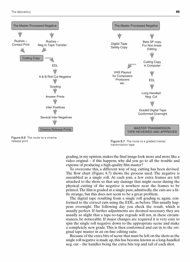
The laboratory 89
grading, in my opinion, makes the final image look more and more like avideo original – if this happens, why did you go to all the trouble andexpense of producing a high-quality film master?
To overcome this, a different way of neg. cutting has been devised.The flow chart (Figure 8.7) shows the process used. The negative isassembled as a single roll. At each join, a few extra frames are leftattached to the shots so that any damage that might occur during thephysical cutting of the negative is nowhere near the frames to beprinted.The film is graded at a single pass; admittedly, the cuts are a lit-tle strange, but this does not seem to be a great problem.
The digital tape resulting from a single roll grading is, again, con-formed to the correct cuts using the EDL, as before. This usually hap-pens overnight. The following day you check the result, which isusually perfect. If further adjustments are deemed necessary they areusually so slight that a tape-to-tape regrade will not, in these circum-stances, be noticeable. If major changes are required it is very easy tospin the single roll negative down to the appropriate scene and makea completely new grade. This is then conformed and cut in to the ori-ginal tape master in an on-line editing suite.
Because of the extra bits of scene that must be left on the shots as thesingle roll negative is made up, this has become known as a long-handledneg. cut – the handles being the extra bits top and tail of each shot.
The Master Processed Negative
Rushes – Contact Print
Rushes –Neg to Tape Transfer
A & B Roll Cut Negative
Grading
Answer Prints
Inter Positives
Several Inter Negatives
Cinema Release Prints
Cutting Copy
EDL
Figure 8.6 The route to a cinemarelease print
The Master Processed Negative
Digital TapeSafety Copy
Beta SP copyFor Non-linear
Editing
Cutting Copyin Computer
VHS Playoutfor Composers
Producersetc.
EDL
Long HandledNeg. Cut
Graded Digital TapeConformed Overnight
MASTER TRANSMISSIONTAPE REVIEWED AND APPROVED
Figure 8.7 The route to a graded mastertransmission tape
Chap-08 12/16/04 3:09 PM Page 89

90 Practical Cinematography
Film grading
It is quite common to find in a DP’s contract either for a cinema filmor a major television drama a clause stating that, subject to their availability, they will be asked to attend, indeed usually supervise, thegrading at the laboratory.This is the moment for the cinematographerto add the final polish to the film.
The process usually takes the form of the DP and the grader fromthe laboratory sitting in a viewing theatre and looking at the cut rushprint, and from this deciding what changes they wish to make in orderto strike the first answer print overnight from an A and B roll cut nega-tive. This answer print will be viewed the following morning and may,with luck, be perfectly acceptable. More likely, at least a secondanswer print is needed. If too many answer prints are ordered, thenbeware, the producer may start to question the quality of your masternegative or whether you are being just a little too fussy and conse-quently spending too much of their post-production budget.
The film grader will be taking notes during the viewing in order tobe sure of the changes the DP wants.These notes are most often a plusor minus sign in front of a printer point change number with thecolour shown. A very experienced DP may be able to communicatewith the grader directly in printer points, but this is not essential noralways preferable. It is quite acceptable to ask for a picture to be a littlemore green, say, or less magenta – which, though technically beingsimilar, sound different and might communicate better your impres-sion of what is needed. Asking for a little more warmth is also per-fectly acceptable. Remember, graders are very experienced and verymuch on your side, so just about any means of communicating yourfeelings of how you wish your pictures to look is fine. It can be hard tocommunicate feelings with printer light numbers.
Unfortunately, there is one absolute fact attached to film grading –if it’s not on the negative there is nothing you can do to get it onto theprint.You can only change the brightness of three colours as they passthrough the negative on their way to the print stock. You cannot, as instill photography, modify in any way the contrast of the print stock or,other than in exceptional and expensive circumstances, change theway the print will be developed.
Telecine grading
All film, from whatever source, that is to be shown on television mustbe converted from a real image on celluloid to an electronic imagestored on videotape. This is achieved by passing the film through adevice called a telecine machine. Simply, this scans the real film imagein the format to be transmitted, say 625 lines in the UK and 525 linesin the USA, and then this signal is recorded onto a conventionalvideotape machine.
Between the telecine machine and the videotape machine is a con-trol desk, with which many adjustments to the image may be per-formed. The telecine can, by the flick of a switch, be converted fromtransferring a positive image from a photographic print to trans-ferring from the master negative, inverting the image to a positive elec-tronically so that the grading and recording are both a positive image.
Chap-08 12/16/04 3:09 PM Page 90
The laboratory 91
Telecine grading is, for me at least, one of the more enjoyable partsof the film-making process. It is akin to being a cabinet maker who,having spent weeks or months making a beautiful piece of furniture, inone day puts the final polish on their work and all is finished.
More often than not, you sit in a room with subdued lighting, all isclean and comfortable and usually a telecine machine sits quietlybehind a glass door in an air-conditioned environment. Before you isa large desk, above which are some high-grade television monitors. Onthe desk are the controls, which will modify your picture in almost anyway you wish.
While the rule, if it’s not on the negative there is nothing you can doto get it on to the print, still applies in all other respects, you can do just as much to the image as you could in a still photography dark-room, if not more, and you can do it instantly!
A first-class modern telecine grading suite can not only change thecolours, as at the chemical laboratory, but can modify the gamma ofthe overall image or just modify the gamma of one colour. It might bepossible to select one area of colour, a pure blue sky say, and work onthe density, colour and gamma of that area alone. This gives the DPmany more tools if you know that the finished picture will be delivered only on tape. For instance, day-for-night, always a dauntingprospect, becomes much more achievable via a good telecine suitethan when you only have a pure photographic process at your disposal.
Do heed the warning, though: it is only wise to use all these tricks ifyou are never going to produce a print as well. If you are, and you goto telecine first, many important people might be very disappointedwith the print if they have already seen your highly modified telecinetransfer.
The telecine process has come a long way.When I first became a DPat the BBC, film was transmitted live as it went through the telecinemachine and only for a major drama production would the DP beallowed to attend a telecine rehearsal. Now it is often in our contractto telecine grade our work if that is what is required. For some yearsnow, it has been popular to transfer the master negative directly totape. Early telecine machines were really lined up for the response ofpositive film and, although the image could be inverted from a nega-tive to a positive, many DPs and producers thought the image morefilmic if the transfer was made from a print, and in those days theywere probably right.
Things have come a long way. A recent film I transferred was fromthe negative via a C-Reality telecine scanning at 2000 lines working ina digital domain. This resolution was maintained right through thetransfer desk, the latest Da Vinci, and only down-converted to 625 lines just before display on the monitor and recording on a digitaltape machine. The quality was stunning. It would be a huge achieve-ment if it were possible, at an economical price, to grade a film for the-atrical release this way and make a print from that grade.This can nowbe achieved via digital intermediates, often referred to as DI.
Chap-08 12/16/04 3:09 PM Page 91
9
Digital intermediates
Why turn a photographic image into digits?
Working through the photographic process from an exposed cameranegative to a cinema release print is a well-known process, discussed inthe previous chapter, and works exceptionally well. Likewise, the scan-ning of a film negative, or print, so that it may be shown on televisionis a well-established procedure and has become very reliable.
Scanning and grading a photographic image for television transmis-sion has some advantages over simply making a photographic printsince, in addition to the ability to alter the red, green and blue compon-ents of the picture, together with overall density, it is easy, electron-ically, to alter the yellow, cyan and magenta components, as well asmake considerable changes to the overall contrast. Up until recently, itwas impossible to take the electronically scanned image, together withany changes made, and return these changes to a photographic cinemaprint without a serious loss in quality. This has now changed.
The first step needed was to have a way of writing an electronicimage back to film with sufficient quality for it to be indistinguishablefrom a conventional cinema print – the Arri Laser Printer, and someothers, now offer this capability.
The second step was the introduction of devices that can scan a mastercamera negative with such subtlety that there was no loss in picturequality between the photographic original and the resultant electronicimage.
Thirdly, the post-production suites, that had for some time been usedto grade photographic images intended for transmission on television,have had their resolution and colour depth improved to such an extentthat they are able to process images well up to full 35 mm film quality.
So, with these three advances it is now possible to scan a cameranegative, make it into an electronic image, manipulate that image andwrite it back to a piece of film with such finesse that the audience willnot be able to tell the difference between a print made by the trad-itional photo mechanical process and one that has been worked on byan electronic process.
But entering the electronic world and returning from it is an expen-sive process, so why would we bother? Because, in addition to greater
92
Chap-09 12/16/04 3:09 PM Page 92
fineness in the grading process, we can manipulate the image in otherways that can improve our storytelling abilities.
The next trick was to find electronic processes that do not degradethe image quality in any way, no matter how many times you re-recordthem, and this is where digital encoding comes in.
The copies of a camera master negative, in the traditional photo-chemical process, are called intermediates. As in the previous chapter,we have seen how intermediate positives and intermediate negativesare used to allow several generations of copies to be made so that acinema release print can be produced. If these intermediates are nowto be replaced by digitally encoded images, it comes as no surprise thatthis process has become known as a digital intermediate, or DI as it ismost often referred to.
What do we mean by ‘digital’?
In order to create a digital image we break up the picture into verysmall elements or pixels. The output from each pixel, depending on itsbrightness, is given a number and this number is then recorded as acode. In order to make up a full colour image, just as in the photo-graphic process, there are three separate sections of these codes, onerelating to the red part of the image, one to the green and one to theblue.The number of options available for different brightnesses recordedby each pixel will significantly affect the quantity of the resultant picture.More options will give a finer picture with a smoother tone range, verylike using a finer grain film.
If you give each small element of the picture, the pixel, the option tohave 1000 differences between recording a black part of an image anda white part, you will get a reasonably fine picture, but if it were pos-sible to break up the tonal range from each pixel into, say, 4000 options,then the result would give a much smoother transition between thevarious tones in the resulting image.
Even to record a decent image comparable with 35 mm film, we aregoing to need something like 2000 pixels across the width of the pic-ture and around 1000 pixels vertically. That’s 2 000 000 pixels perframe and, as we want to give each pixel at least 1000 options ofbrightness, the total number of options we will need to record will be2 000 000 000. So far, we have only recorded one of the three necessarycolours, so for a full colour single frame we need 6 000 000 000 options.At 24 frames per second, we are going to need to have a huge record-ing ability unless we can find a way to simplify matters.
The binary code
A binary code employs a combination of zeros and ones in an organ-ized way to write any value. The numbers of zeros and ones useddetermines how many options you will have available.
Just one option allows you to write two numbers, as zero will repre-sent a number and one will represent another.Yet if we go up just onestep further and allow two options of zeros and ones we can nowrecord four different numbers, for we have the options of 00, 01, 10and 11. This we call a two-bit code, where two bits of information are
Digital intermediates 93
Chap-09 12/16/04 3:09 PM Page 93

94 Practical Cinematography
used to write four combinations, with each combination representingone value.
The great advantage of this system is that one can easily design amachine, or electronic circuit, to recognize this code, as we can tell itone is represented by ‘On’ and zero is represented by ‘Off’. So, as weare only asking our machine to tell if it is on or off to understand allthe numbers we require, we have gained a huge advantage – we cancopy our string of codes as many times as we like, with absolute accur-acy, and even the most stupid of machines can tell if it is on or off.
Here lies the advantage of digital copying over photographic copy-ing; every time you make a photographic copy there will be some lossin quality, no matter how small, but every digital copy should be anexact replica of the original. We can now, therefore, make as manycopies, or intermediates, as we wish.
But how many combinations of zeros and ones should we assign toeach pixel to get an exact representation of our photographic original?Well, perceived wisdom tells us we need 10 or 12 combinations of zerosand ones in order that the digital intermediate process remains seam-less. Figure 9.1 shows how the number of combinations available withdifferent numbers of zeros and ones moves up to an astounding 4096for 12-bit encoding.
Linear and logarithmic sampling
There is a way of encoding the original scanning of the camera nega-tive that can both make the picture more appealing to the eye and, atthe same time, reduce the size of the digital files used to store theimages. It involves the use of logarithmic sampling rather than the tra-ditional linear sampling.
Figure 9.1 The effect of addingmore bits to the binary code
1-bit 0 (or 1)2 � 2 values
2-bit 0 12 � 2 � 4 values
4-bit 0 1 0 12 � 2 � 2 � 2 � 16 values
6-bit 0 1 0 1 0 12 � 2 � 2 � 2 � 2 � 2 � 64 values
8-bit 0 1 0 1 0 1 0 12 � 2 � 2 � 2 � 2 � 2 � 2 � 2 � 256 values
10-bit 0 1 0 1 0 1 0 1 0 12 � 2 � 2 � 2 � 2 � 2 � 2 � 2 � 2 � 2 � 1024 values
12-bit 0 1 0 1 0 1 0 1 0 1 0 12 � 2 � 2 � 2 � 2 � 2 � 2 � 2 � 2 � 2 � 2 � 2 � 4096 values
Chap-09 12/16/04 3:09 PM Page 94
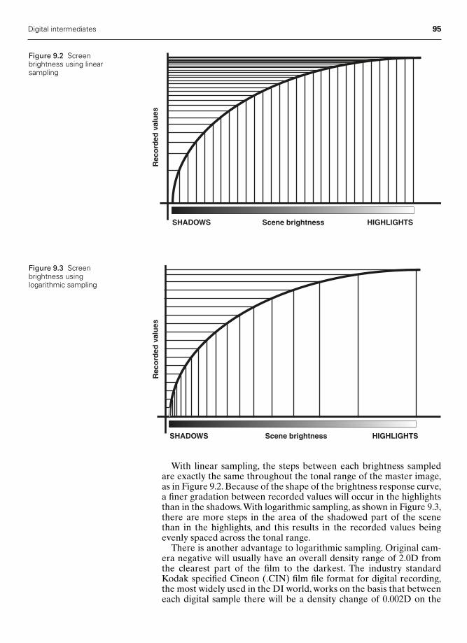
Digital intermediates 95
With linear sampling, the steps between each brightness sampledare exactly the same throughout the tonal range of the master image,as in Figure 9.2. Because of the shape of the brightness response curve,a finer gradation between recorded values will occur in the highlightsthan in the shadows.With logarithmic sampling, as shown in Figure 9.3,there are more steps in the area of the shadowed part of the scenethan in the highlights, and this results in the recorded values beingevenly spaced across the tonal range.
There is another advantage to logarithmic sampling. Original cam-era negative will usually have an overall density range of 2.0D fromthe clearest part of the film to the darkest. The industry standardKodak specified Cineon (.CIN) film file format for digital recording,the most widely used in the DI world, works on the basis that betweeneach digital sample there will be a density change of 0.002D on the
SHADOWS HIGHLIGHTSScene brightness
Rec
ord
ed v
alu
es
Figure 9.2 Screenbrightness using linearsampling
SHADOWS HIGHLIGHTSScene brightness
Rec
ord
ed v
alu
es
Figure 9.3 Screen brightness using logarithmic sampling
Chap-09 12/16/04 3:09 PM Page 95
96 Practical Cinematography
camera negative. If we sample in a linear pattern, the 11-stop dynamicrange of a modern camera negative will need a 13-bit file to hold allthat data using 0.002 intervals of density between samples.This meansthat, in order to get sufficient data for the shadows to look real, theremust be 8192 options of recordable brightness for each pixel.
However, if a tonal range of 11 stops on the camera negative is sam-pled in a logarithmic way, the same amount of necessary informationcan be recorded on a 10-bit file, which has only 1024 options. Thismeans much smaller files are needed but the audience will still see animage of equivalent quality.
Image acquisition
At the start of the DI process it is necessary to scan the photographicimage so that we can write it in the binary code. The most importantdecision is what digital resolution we use and this is described byreferring to the number of pixels the horizontal width of the picture isbroken up into.There is much discussion in the post-production worldas to how many horizontal pixels are needed, with almost as manyopinions as there are post-production houses, so I am going to give myopinion, and I have taken very good advice on this.
A 35 mm master camera negative is almost universally agreed to havethe equivalent of a digital image of 4000 pixels horizontally.Therefore,if you wish to take a shot, manipulate it digitally and return it to thecut camera master negative, you must scan at 4000 pixel resolution inorder that no discernible degradation in picture quality occurs whenyou make the photographic intermediates.
If you are going to scan your camera master and do all your inter-mediates digitally, only returning to film for the release print, or at theworst the intermediate photographic negative, then scanning youroriginal at 2000 pixels horizontally will be enough and can produce animage on the cinema screen every bit as good as the purely photo-graphic method described above.
Incidentally, we refer to a picture with 4000 horizontal pixels as hav-ing a 4k resolution and one with 2000 pixels as 2k.
Why the difference? The traditional route from camera master neg-ative to the cinema release print usually looks like this:
1 Camera negative – printed to intermediate positives.2 Intermediate positive – printed to intermediate negatives.3 Intermediate negatives – printed to cinema release prints.4 Cinema release print – to cinema screen.
It is an inescapable fact that every time you make a photographic copyyou must lose some picture quality; therefore, if you go through thisprocess starting with 4k camera negative you will end up on the screenwith something having a poorer resolution.
To satisfy the resolution of an audience sitting in the optimum view-ing position in a cinema, the screen picture quality must have a hori-zontal resolution equivalent to 1000 pixels or better. Only then willthey consider the image to be sharp. In order to achieve this, one muststart with a camera negative having a 4k resolution and that will, afterthe degradation due to the copying process, give roughly a 1.2k imageon the cinema screen and this, therefore, satisfies the audience criteria.
Chap-09 12/16/04 3:09 PM Page 96

With the DI route things are different, for as we have seen the copy-ing process here is loss free, so it is perfectly reasonable to supposethat starting with a 2k scan, and manipulating it at this resolution, it isstill easily possible to show the final scan out to film on the cinemascreen with 1.2k resolution; thus, the audience should not be able totell any difference in quality between photographic intermediates anddigital intermediates.
If, at the end of the DI process, we were to show the stored digitalimages directly onto the cinema screen via a high-quality digital pro-jector, it is now possible to show all of the 2k image on the screen,arguably producing a higher quality image than a film print is capable of.
The 16 mm DI route
Blowing up a 16 mm negative to a 35 mm print never looks as good asa 35 mm negative. Using the DI option it is possible to scan the 16 mmmaster at 2k, or even 4k resolution, though the latter will be apprecia-bly more expensive. If you do that and write out the DI to a print, theresults can be quite remarkable. This is because a 4k scan of a 16 mmmaster will result in at least the required 1.2k resolution on the cinemascreen.
Deliverables
A considerable advantage of working with a DI is the multitude ofversions that can be taken from the DI master. You can create simul-taneously, or at any later date, a film copy, a digital data file that may,for instance, be delivered on a server to a cinema, a standard definitiontape in any standard for transmission on television, an HD video copy,a DVD, have the ability to access the movie on the web and manymore formats that exist now or may come into being in the future.Remember, the DI master will produce a picture for any screen and,as we have seen, it will more than satisfy the acutance of the humaneye – quite an argument for a DI master being a reliable way to future-proof the movie.
Digital intermediates 97
Chap-09 12/16/04 3:09 PM Page 97

This page intentionally left blank

Part Three
TheCinematographer’sCraft
Chap-10 12/16/04 3:10 PM Page 99

This page intentionally left blank
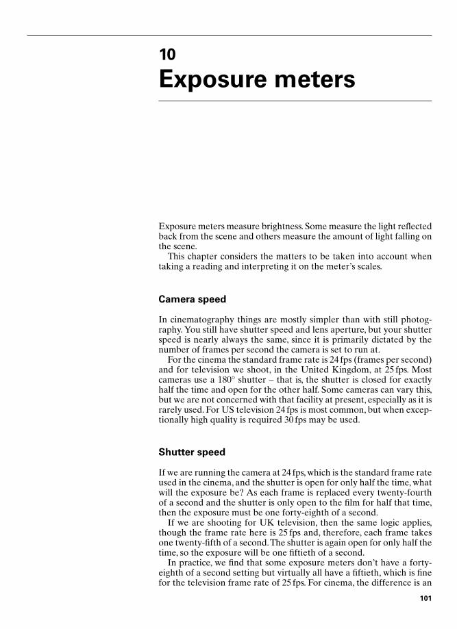
10
Exposure meters
Exposure meters measure brightness. Some measure the light reflectedback from the scene and others measure the amount of light falling onthe scene.
This chapter considers the matters to be taken into account whentaking a reading and interpreting it on the meter’s scales.
Camera speed
In cinematography things are mostly simpler than with still photog-raphy. You still have shutter speed and lens aperture, but your shutterspeed is nearly always the same, since it is primarily dictated by thenumber of frames per second the camera is set to run at.
For the cinema the standard frame rate is 24 fps (frames per second)and for television we shoot, in the United Kingdom, at 25 fps. Mostcameras use a 180° shutter – that is, the shutter is closed for exactlyhalf the time and open for the other half. Some cameras can vary this,but we are not concerned with that facility at present, especially as it israrely used. For US television 24 fps is most common, but when excep-tionally high quality is required 30 fps may be used.
Shutter speed
If we are running the camera at 24 fps, which is the standard frame rateused in the cinema, and the shutter is open for only half the time, whatwill the exposure be? As each frame is replaced every twenty-fourthof a second and the shutter is only open to the film for half that time,then the exposure must be one forty-eighth of a second.
If we are shooting for UK television, then the same logic applies,though the frame rate here is 25 fps and, therefore, each frame takesone twenty-fifth of a second.The shutter is again open for only half thetime, so the exposure will be one fiftieth of a second.
In practice, we find that some exposure meters don’t have a forty-eighth of a second setting but virtually all have a fiftieth, which is finefor the television frame rate of 25 fps. For cinema, the difference is an
101
Chap-10 12/16/04 3:10 PM Page 101

error of 4 per cent, and that in the direction of overexposure, which isthe safer direction.
Before we can discuss the different types of exposure meter, weneed to know a little of how they are designed.
Average scene reflectance values
There is an international agreement as to what represents an averagescene. It has been determined that the average surface of an averagescene will reflect 18 per cent of the light landing on it.This is importantas all exposure meters are based on this premise – they believe theyare looking at something that has a reflectance value of 18 per cent.We can use this knowledge to interpret the reading that our meter isgiving us.
For instance, Caucasian skin tone, the most photographed thing inthe western world, is clearly reflecting more than 18 per cent – com-pare it with a Kodak standard 18 per cent grey card and you will seethe difference. Fortunately, the difference is usually around one stop,i.e. the skin is reflecting twice as much light as the 18 per cent card, sois therefore one stop brighter. There will be occasions when we needto make this compensation – for example, when we have taken a close,reflected reading off someone’s face.
Types of exposure meter
There are four basic types of exposure meter. Some work in differentways, though they have one thing in common, as we have seen – theyall think they are looking at a scene with an average reflectance valueof 18 per cent.
The five basic types are:● Built-in camera meters.● Reflected light meters.● Incident light meters.● Spot meters.● A fifth type of meter, the combined meter, has recently come onto
the market.
Built-in camera metersBuilt-in camera meters can be very simple or quite sophisticated. Thetwo you will come across most often in filming will be those in the ArriSR and the Aaton cameras. Both are quite sophisticated. They take aportion from the centre of the frame to be shot and give an averageexposure for this portion, adding to this a smaller value for the rest ofthe frame.This is known as ‘centre weighting’ a meter, as it takes muchmore notice of the centre of the frame than the rest of it.
The Arri SR meter takes a small portion of the light that has beenreflected onto the camera’s focusing screen and sends it to the meter’ssensitive cell via some fairly sophisticated optics. The Aaton takesquite a different approach in that the photosensitive cell looks directlyat the emulsion in the film gate. The Aaton therefore needs to be
102 Practical Cinematography
Chap-10 12/16/04 3:10 PM Page 102

flicked over one frame to take a reading when the camera is not run-ning. In practice, both methods are very accurate and reliable.
These meters work very well on an average outdoor scene, especiallyif the camera is pointed down to exclude the sky, a reading is taken andset, and the camera is then tilted up to the original composition.
Their disadvantage is that they make no allowance for any dramaticdecisions from the cinematographer, since they can only work onaverages.
Reflected light metersReflected light meters work in a very similar way to built-in meters –in fact, they are more or less a hand-held version of the same. Beinghand-held, they do give the cinematographer more control, as theycan be pointed at different parts of the scene to analyse the variousbrightnesses within that scene.
Perhaps the most common reflected light meter is the Weston Master.This meter, with some improvements, has been around for many years.Unfortunately, even in its latest version, it is not very sensitive and canonly really be used for outdoor photography. Nevertheless, as it is aclassic of its kind it is worth considering.
It has a grid that may or may not cover the meter’s cell, giving twobrightness ranges on the meter. As you cover the cell with the grid, anew scale comes before the needle automatically, giving you the cor-rect read-outs for the two ranges. An Invercone attachment can beadded to the Weston to turn it into an incident light meter.
Reflected light meters can be pointed at an 18 per cent grey card togive an average reading of the scene and will then behave very simi-larly to incident light meters.
Incident light metersAs you would expect from their name, these meters measure the lightincident to the scene – that is, the light falling onto the scene. They dothis, in the main, by having a white dome over the meter’s cell that inte-grates, or adds together, the light from all directions in front of the meter.This dome is usually referred to as an integrating or photo sphere.Thesemeters are especially good for exposing reversal films. The dome doestend to collect too much light from the sky, so you will often see photog-raphers holding their hand above the dome to shield it from this effect.
Incident light meters are also very good at measuring brightnessratios, especially those where the dome can be replaced with a flatwhite plate, making the meter much more directional.
An even more sophisticated integrator is the Weston Inverconeattachment for the Weston meter. Here the integrator is not a simpledome but a hollow white plastic ring with a dimple in the middle. Thishas been very carefully designed so that there are exactly the samepercentage areas of plastic facing each direction as has the humanface.Thus, one gets a very accurate exposure reading for photographinga Caucasian human being. If you were foolish enough to take anInvercone apart, you would find that between its two top inner andouter surfaces there is a small piece of paper.This is in there to reduceslightly the effect of overhead light on the subsequent reading, otherwise
Exposure meters 103
Chap-10 12/16/04 3:10 PM Page 103
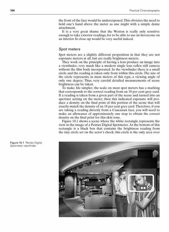
the front of the face would be underexposed.This obviates the need tohold one’s hand above the meter as one might with a simple domeattachment.
It is a very great shame that the Weston is really only sensitiveenough to take exterior readings, for to be able to use an Invercone onan interior lit close-up would be very useful indeed.
Spot metersSpot meters are a slightly different proposition in that they are notexposure meters at all, but are really brightness meters.
They work on the principle of having a lens produce an image intoa viewfinder, very much like a modern single lens reflex still camerawithout the film body incorporated. In the viewfinder there is a smallcircle and the reading is taken only from within this circle. The size ofthe circle represents, in most meters of this type, a viewing angle ofonly one degree. Thus, very careful detailed measurements of scenebrightness can be taken.
To make life simpler, the scale on most spot meters has a markingthat corresponds to the correct reading from an 18 per cent grey card.If a reading is taken from a given part of the scene and turned into anaperture setting on the meter, then this indicated exposure will pro-duce a density on the final print of this portion of the scene that willexactly match the density of an 18 per cent grey card.Therefore, if youare taking a reading directly from a Caucasian face, you will need tomake an allowance of approximately one stop to obtain the correctdensity on the final print for this skin tone.
Figure 10.1 shows a scene where the white rectangle represents theview in the image of a Pentax Digital Spotmeter.At the bottom of thisrectangle is a black box that contains the brightness reading from the tiny circle set on the actor’s cheek; this circle is the only area over
104 Practical Cinematography
Figure 10.1 Pentax DigitalSpotmeter viewfinder
Chap-10 12/16/04 3:10 PM Page 104
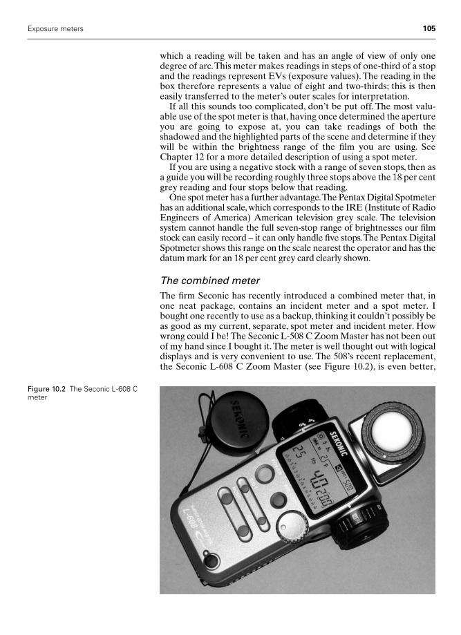
which a reading will be taken and has an angle of view of only onedegree of arc.This meter makes readings in steps of one-third of a stopand the readings represent EVs (exposure values). The reading in thebox therefore represents a value of eight and two-thirds; this is theneasily transferred to the meter’s outer scales for interpretation.
If all this sounds too complicated, don’t be put off. The most valu-able use of the spot meter is that, having once determined the apertureyou are going to expose at, you can take readings of both the shadowed and the highlighted parts of the scene and determine if theywill be within the brightness range of the film you are using. SeeChapter 12 for a more detailed description of using a spot meter.
If you are using a negative stock with a range of seven stops, then asa guide you will be recording roughly three stops above the 18 per centgrey reading and four stops below that reading.
One spot meter has a further advantage.The Pentax Digital Spotmeterhas an additional scale, which corresponds to the IRE (Institute of RadioEngineers of America) American television grey scale. The television system cannot handle the full seven-stop range of brightnesses our filmstock can easily record – it can only handle five stops.The Pentax DigitalSpotmeter shows this range on the scale nearest the operator and has thedatum mark for an 18 per cent grey card clearly shown.
The combined meterThe firm Seconic has recently introduced a combined meter that, inone neat package, contains an incident meter and a spot meter. Ibought one recently to use as a backup, thinking it couldn’t possibly beas good as my current, separate, spot meter and incident meter. Howwrong could I be! The Seconic L-508 C Zoom Master has not been outof my hand since I bought it.The meter is well thought out with logicaldisplays and is very convenient to use. The 508’s recent replacement,the Seconic L-608 C Zoom Master (see Figure 10.2), is even better,
Exposure meters 105
Figure 10.2 The Seconic L-608 Cmeter
Chap-10 12/16/04 3:10 PM Page 105

as you don’t need to choose between a meter with a still photographyor movie type scale, the new meter does both, and it also has the addedimprovement of the spot meter reading showing in the viewfinder.Remarkably, the optical path for the spot meter in these meters suffersfrom no discernible flare, the bane of most spot meters, this despitehaving a four-to-one zoom facility built in.
Figure 10.3 shows my own collection of meters, which are all in regu-lar use on a daily basis.They are, from bottom left going clockwise, myCinemeter II, the Seconic 508 C Zoom Master, the Pentax DigitalSpotmeter and, though not strictly an exposure meter, my MinoltaColour Temperature Meter.
106 Practical Cinematography
Figure 10.3 My own collection ofmeters
Chap-10 12/16/04 3:10 PM Page 106
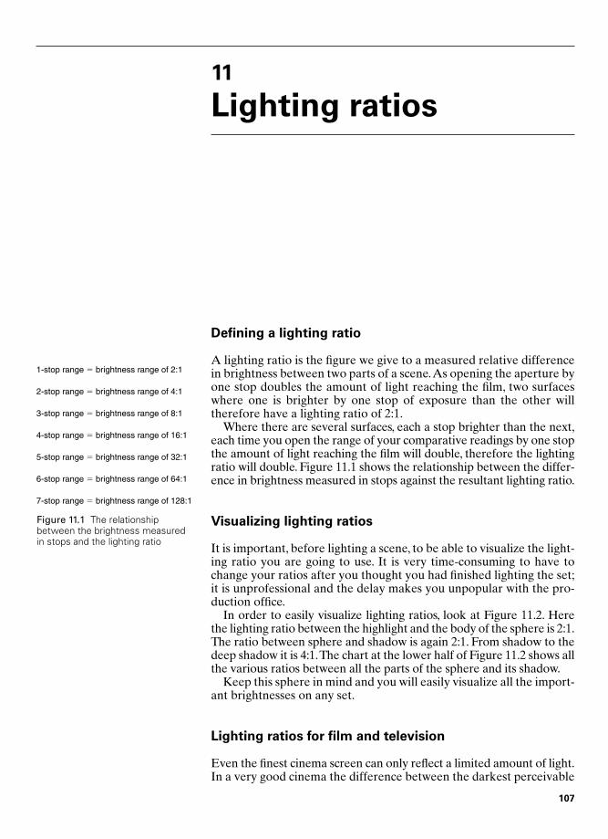
11
Lighting ratios
Defining a lighting ratio
A lighting ratio is the figure we give to a measured relative differencein brightness between two parts of a scene.As opening the aperture byone stop doubles the amount of light reaching the film, two surfaceswhere one is brighter by one stop of exposure than the other willtherefore have a lighting ratio of 2:1.
Where there are several surfaces, each a stop brighter than the next,each time you open the range of your comparative readings by one stopthe amount of light reaching the film will double, therefore the lightingratio will double. Figure 11.1 shows the relationship between the differ-ence in brightness measured in stops against the resultant lighting ratio.
Visualizing lighting ratios
It is important, before lighting a scene, to be able to visualize the light-ing ratio you are going to use. It is very time-consuming to have tochange your ratios after you thought you had finished lighting the set;it is unprofessional and the delay makes you unpopular with the pro-duction office.
In order to easily visualize lighting ratios, look at Figure 11.2. Herethe lighting ratio between the highlight and the body of the sphere is 2:1.The ratio between sphere and shadow is again 2:1. From shadow to thedeep shadow it is 4:1.The chart at the lower half of Figure 11.2 shows allthe various ratios between all the parts of the sphere and its shadow.
Keep this sphere in mind and you will easily visualize all the import-ant brightnesses on any set.
Lighting ratios for film and television
Even the finest cinema screen can only reflect a limited amount of light.In a very good cinema the difference between the darkest perceivable
Figure 11.1 The relationshipbetween the brightness measuredin stops and the lighting ratio
1-stop range � brightness range of 2:1
2-stop range � brightness range of 4:1
3-stop range � brightness range of 8:1
4-stop range � brightness range of 16:1
5-stop range � brightness range of 32:1
6-stop range � brightness range of 64:1
7-stop range � brightness range of 128:1
107
Chap-11 12/16/04 3:11 PM Page 107

108 Practical Cinematography
black and the whitest white will measure a difference of no more thanseven stops.The black will never read as absolute black, since there willalways be some spurious light, even if it is only that which has arrived asatmospheric flare, for the highlights in the scene displayed have to travelthrough the atmosphere in the cinema. The cinematographer’s lot hasbeen much improved since smoking was banned in many cinemas.
This means that the maximum lighting ratio that we can display inthe final picture on the screen is 128:1, the equivalent of seven stops ofexposure difference. It is important to realize that any parts of the sceneoutside this ratio of 128:1 will have no detail or information in themwhatsoever.They will appear as either solid black or solid white.Keepingall the important information in a scene within the lighting ratio of thefinal delivery system is therefore crucial to the success of the scene.
When shooting for television, matters are more constrained. If youlook at your television screen when it is switched off, it will appear tobe dark grey. This is as dark as it will ever get. When a picture is dis-played on the television screen, parts of that picture only appearblack, or darker than the screen when switched off, because of the wayour eyes and brain expect to perceive the relative brightness betweenthe highlights and the shadows. A strong highlight anywhere in thescene will make the blacks appear darker still.
Even the finest television screen can only display a brightness ratioof 32:1 or the equivalent range of five stops of exposure range. It isimportant, therefore, not to light anything in a scene that you feel theaudience should be able to perceive, even if only as a faint texture, out-side a lighting ratio of 32:1. As with the cinema, but now over a muchrestricted range, any part of the scene outside this range will appear aseither solid black or solid white. Parts of the scene that are solid blackor white on a television screen are far less pleasant than in the cinema,because they attract electronic noise and, as this is an unnatural phenomenon in normal vision, even an untrained viewer’s eye andbrain will instantly know something is wrong. This must therefore beavoided.
Deep Shadow
Shadow
Sphere(mid-tone)
Highlight
Lighting Ratios on Sphere
Highlight : Sphere � 2:1Sphere : Shadow � 2:1Shadow : Deep Shadow � 4:1
Highlight : Shadow � Highlight : Sphere � Sphere : Shadow � 4:1Highlight : Deep Shadow � Highlight : Sphere � Sphere : Shadow � Shadow : Deep Shadow � 16:1
Sphere : Deep Shadow � Sphere : Shadow � Shadow : Deep Shadow � 8:1
Figure 11.2 The relationshipbetween a highlight, themid-tones, a shadow and adeep shadow
Chap-11 12/16/04 3:11 PM Page 108
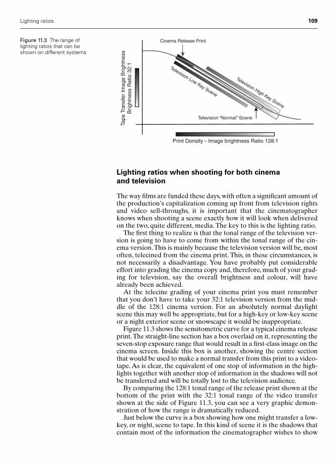
Lighting ratios when shooting for both cinema
and television
The way films are funded these days, with often a significant amount ofthe production’s capitalization coming up front from television rightsand video sell-throughs, it is important that the cinematographerknows when shooting a scene exactly how it will look when deliveredon the two, quite different, media. The key to this is the lighting ratio.
The first thing to realize is that the tonal range of the television ver-sion is going to have to come from within the tonal range of the cin-ema version.This is mainly because the television version will be, mostoften, telecined from the cinema print. This, in these circumstances, isnot necessarily a disadvantage. You have probably put considerableeffort into grading the cinema copy and, therefore, much of your grad-ing for television, say the overall brightness and colour, will havealready been achieved.
At the telecine grading of your cinema print you must rememberthat you don’t have to take your 32:1 television version from the mid-dle of the 128:1 cinema version. For an absolutely normal daylightscene this may well be appropriate, but for a high-key or low-key sceneor a night exterior scene or snowscape it would be inappropriate.
Figure 11.3 shows the sensitometric curve for a typical cinema releaseprint.The straight-line section has a box overlaid on it, representing theseven-stop exposure range that would result in a first-class image on thecinema screen. Inside this box is another, showing the centre sectionthat would be used to make a normal transfer from this print to a video-tape. As is clear, the equivalent of one stop of information in the high-lights together with another stop of information in the shadows will notbe transferred and will be totally lost to the television audience.
By comparing the 128:1 tonal range of the release print shown at thebottom of the print with the 32:1 tonal range of the video transfershown at the side of Figure 11.3, you can see a very graphic demon-stration of how the range is dramatically reduced.
Just below the curve is a box showing how one might transfer a low-key, or night, scene to tape. In this kind of scene it is the shadows thatcontain most of the information the cinematographer wishes to show
Lighting ratios 109
Tape
Tra
nsfe
r Im
age
Brig
htne
ssB
right
ness
Rat
io 3
2:1
Television Low Key Scene
Television High Key Scene
Cinema Release Print
Television “Normal” Scene
Print Density – Image brightness Ratio 128:1
Figure 11.3 The range oflighting ratios that can beshown on different systems
Chap-11 12/16/04 3:11 PM Page 109

the audience, so the transfer from this end of the curve only will haveall the shadow detail seen when the original scene was shown in thecinema, but will have lost the equivalent of two stops of informationfrom the highlights.
Above the curve is a further box showing the same five-stop range asthe lower box, but now representing the portion of the print that youwould choose to transfer if it were a high-key scene, maybe a snow orseascape. Now, of course, all the highlight information seen in the cin-ema is retained and the equivalent of two stops of shadow detail is lost.
It is possible, and indeed quite correct, to select any five-stop or 32:1brightness range from the print when making a transfer to tape.Because this selection process is so important, I strongly believe allcinematographers should attend the telecine transfer of their workand should have made themselves fully conversant with the work ofthe telecine grader or colourist.
Using lighting ratios on the set
The most common use of lighting ratios is in the control of how welight the human face. If you have successfully lit a face and you find itparticularly pleasing for the mood you are looking for, then the sim-plest way of noting your success, at least in part, is to record, or simplyremember, the lighting ratio.
If you were lighting a rather light piece with, say, a leading lady agedperhaps late forties but playing a part written as 30 or so, a lightingratio of 2:1 would be very flattering. This is because, with the brighterside of the face only twice the brightness of the darker side, the shadows in the smile lines by her eyes would only be half the brightnessof the lit side of the face.As there would be little difference in brightnessbetween the smooth skin and the lined skin, the lines would hardlyshow – all very flattering.
Using the same principle, but in reverse, your leading man in thesame piece might benefit from a lighting ratio of 4:1. This would makehim, certainly by comparison with his leading lady, a little more ruggedthan perhaps in real life, often a benefit.
Were you to be lighting a more dramatic piece, say a thriller, thenyou might let the lighting ratio on your leading man rise to 8:1 or threestops difference. The night scenes for the same film might rise to 16:1,but this is very dramatic – the detail in the shadowed side of the face isgoing to start to disappear soon and will almost certainly show asblack on television.
Controlling the whole scene
As we have seen, the overall lighting ratio for a picture that is to beshown on television must be kept within 32:1, a five-stop range, and forcinema presentation it must be kept within 128:1, a seven-stop range.
The most effective way of discovering which parts of the subject willfall within the acceptable range is by measuring the brightnesses witha spot meter. A method of controlling the overall lighting ratio, andindeed controlling all the tones in the scene, is discussed in the nextchapter.
110 Practical Cinematography
Chap-11 12/16/04 3:11 PM Page 110

12
Three-point imagecontrol
There’s no such thing as exposure latitude
Many photographers refer to a particular film stock as having plentyof latitude; indeed, stock manufacturers often sell certain stocks ashaving great, or extended, latitude. If we are to produce the very finestimages, it is important to abandon all thoughts of film having latitudeand use all the tonal range of the film.
If you are using a film stock with the ability to record an image witha tonal range covering seven stops (that is, a lighting ratio of 128:1),and you knew that the image was only ever going out on television,which can only transmit a lighting ratio of 32:1, or five stops of tonalrange, then you could say that you had two stops’ latitude, one stopabove correct exposure and one stop below perfect exposure. But whynot go for a more appropriate exposure every time?
Even when shooting for television you might not want to put thefive-stop range in the middle of the sensitometric curve. If you wereshooting a night exterior you might wish to lay your exposure right onthe bottom five stops of the full exposure range, thus taking advantageof the curved response at the bottom end on the sensitometric curve.This would be very sensible, as the non-linear response to extremeshadow detail at this point in the film’s sensitivity is very akin to thehuman eye/brain response and can therefore, in these circumstances,look both appealing and appropriate.
The same is true of a scene containing mainly highlights, say a snows-cape. Here you may decide to peg all your important tones right at thetop of the sensitometric curve, thus compressing the extreme whites asthey will sit on the non-linear part of the curve, where all the brightwhites start to go to absolute white. This can have the effect of appear-ing to extend the information-recording ability of the film well into theshadows, where you may wish to show more information.
If you are shooting with a film having a seven-stop overall range andyou are going to show the resultant picture in the cinema, where, as wehave seen, a really good projector/screen set-up can show the fullseven-stop range, then clearly you have no latitude whatsoever.
111
Chap-12 12/16/04 3:12 PM Page 111

If we are to work at these extremes, or even if we wish to be certainthat we are placing our chosen tones right in the middle of thestraight-line section of the curve, then we will need a simple and accu-rate method of measuring the brightnesses in the scene and relatingthem to the chosen film’s recording ability.
Three-point image control
To work to the accuracy required above you cannot use an incident lightmeter. An incident meter can make no allowance for the reflectivity ofthe subject behind it and that reflectivity can vary over huge margins.
A reflected light meter is required and one where the user is certainof the exact area over which the reading is being taken. Such a thing iscalled a spot meter. You will find a full description of a spot meter inChapter 10.
There is a very simple way of using a spot meter to very quickly giveyou all the information you need for the most accurate positioning ofthe tones of your scene on the sensitometric curve of the film you areusing. After a little experience you will not even have to think aboutthe sensitometry at all.
Point 1In order to establish the correct aperture to set on the lens, take areading on the most important subject in the scene.As this will usuallybe your main character in the scene, then use their lit skin tone. If theyare a Caucasian then the reading on your spot meter will be one stopover the setting for an 18 per cent grey card.
As we have seen, the meter expects to be pointed at something hav-ing a reflectance value of 18 per cent and Caucasian skin usually has areflectance of around 36 per cent. This means that if the skin readsT5.6 then the lens should be set to T4.You can check this by substitut-ing the person with an 18 per cent grey card; this will read T4. In fact,using the card is a very good way of setting this point when the personis not available. Remember, the card must be placed in the exact pos-ition of the face and should be set so that all the light that will fall onthe bright side of the face falls on the card.
The only other caveat is that all the readings for this technique mustbe taken from in front of or very near to the lens, for only then will thereflectance of all the surfaces in the scene be the same for the spotmeter as for the film.
Point 2The second most important part of most scenes to most cinematog-raphers is the shadows, so measuring these becomes Point 2 of thetechnique. We know that for cinema our tonal range goes around fourstops below camera aperture; therefore, without changing any of thesettings on your spot meter, look into the shadows in your scene. Fourstops below the exposure we have chosen, T4, is T0.9 – therefore, anyshadows that read above T0.9 will just have detail in them when shownon the cinema screen and any that read below this figure will come outas solid black.
112 Practical Cinematography
Chap-12 12/16/04 3:12 PM Page 112
Point 3We know that the chosen film in this example has a tonal range of theequivalent of seven stops and therefore will record up to three stops of information above the setting for the 18 per cent grey card. As wehave established that the lens is to be set at T4, then this upper cut-offpoint will be a reading of T11, three stops above T4.
Now explore the highlights in your scene. Any parts of the scenethat read below T11 will have information in them; any that read aboveT11 will appear in the cinema as even, clear, white.
There is one more matter to remember when reading the highlights.When you get a reading a certain amount above the maximum record-able by the film, the image of that subject will grow, as pouring so muchenergy, light, into the film’s emulsion causes it to disperse in variousways. Also, there is a likelihood of lens flare at these very high bright-nesses. Containing this overexposure within two stops above the maxi-mum recordable will usually prevent this happening.
Relating the three points to the sensitometric curve
Let us assume we are about to photograph an exterior scene with a200 ISO film we have used before and we know its characteristicsquite well. Experience tells us that with this film we will be able torecord a seven-stop tonal range and that we will still get a little detailin the highlights if they are three stops brighter than the aperture wehave set on the camera, and we still get just a little detail in the shadows when they read four stops below camera aperture.
Figure 12.1 shows a scene with the viewfinder image of a PentaxDigital Spotmeter overlaid on the scene. Let us say we were using our200 ASA film, then the reading on the girl’s face, Point 1, would be 8 inthe viewfinder.Translating this on the meter’s scale, this becomes T5.6.We would therefore set the lens to T4, as her skin tone will be reflect-ing about one stop more than an 18 per cent grey card.This means thatcamera aperture would now be represented by a reading of 7 in thePentax viewfinder.
Checking the doorway to the right of the building, the shadow, andtherefore Point 2, we get a reading of 4 and one dot in the viewfinder –that is, two and two-thirds stops below camera aperture and thereforeone-third of a stop above black. Converting this to an exposure we getT1.0; therefore, the doorway will be just on the very edge of havinginformation in the image and the door will, most likely, have woodgrain just discernible in the image.
A reading taken on the highlight on the wall just below the dome onthe top of the building is 9 and two dots in the viewfinder. As each dotin a Pentax finder represents one-third of a stop, this gives us a read-ing two and two-thirds stops above the camera aperture, still one-thirdof a stop within the three-stop limit, so there will still be a little colourand detail in these highlights – they will not have lost information orbecome pure white.
All the other tonesIt is now possible to take readings from any or all the other tones andsee exactly where they are going to sit within or outside the tonal range
Three-point image control 113
Chap-12 12/16/04 3:12 PM Page 113

of the film. With a little practice you will be able to imagine the bright-ness in the final image as it relates to the nearest of the three cardinalpositions you have set against the stop you have put on the lens.
Adjusting the tonesIf you find that there is an important part of the scene that has read alittle above the maximum white but you wish to photograph it, one rela-tively simple solution is to light the subject’s face a little brighter. Thiswill enable you to stop down enough to bring the highlight within therecordable tonal range. You will now need to recheck your shadows tomake sure none of them have now fallen outside the film’s tonal range.
More simply, if there are some shadows that fall below the record-able tonal range, then by simply adding a little more fill light you willbring them up to a recordable level. On an exterior this might simplybe done with a reflector, for instance.
Control for television
Three-point image control works just as well when filming for televi-sion transmission. The only difference is that you have only two andtwo-thirds stops of recordable image below the reading on an 18 percent grey card and two and one-third above. In practice, with modernfilm stocks, you can approximate this safely to three stops below andtwo stops above.
114 Practical Cinematography
4
Logarithm of Exposure created by Brightness of scene
Den
sity
Cre
ated
on
the
Neg
ativ
e
18%Reflectance
8
9
Figure 12.1 How scene tonesrelate to the sensitometric curve
Chap-12 12/16/04 3:12 PM Page 114
13
Using the 18 per centgrey card
The messenger
Perhaps the most important use of the grey card is as a messenger tothe processing laboratory. By adjusting the brightness, and indeed thecolour, of the grey card then photographing it before you shoot ascene you have, possibly, the most powerful communication tool incinematography.
In order to use this tool you must first tell the processing laboratoryyou need them to participate. You can do this in three ways:
1 Before shooting, explain to the laboratory that, at the beginning of every day’s rushes, there will be a grey card and would they,please, always grade the following scenes to that grey card. Tellthem that when you want the grading changed you will put a newcard on.
2 When the grading is to be changed, always break the roll and starta new roll.This way the laboratory grader does not have to inspectall the rushes for cards – they only need to check the beginnings ofrolls.This is important, as it means the negative receives less hand-ling and therefore has less chance of being damaged. It also savesthe grader a lot of time and this encourages them to be helpful.Graders are human too.
3 At the top of the lab report sheet, always get the loader to write,very clearly, ‘Grade To Grey Scales’.This is in case the grader whonormally prints the rushes every night is off for some reason andthe new grader does not know you are using this technique.
I have my own grey card which has printed on white Dymo labelling‘Please Grade the Following Scenes to this 18 per cent Grey Card’.When that is photographed at the front of the roll there can be verylittle misunderstanding as to the requirements.
115
Chap-13 12/16/04 3:12 PM Page 115
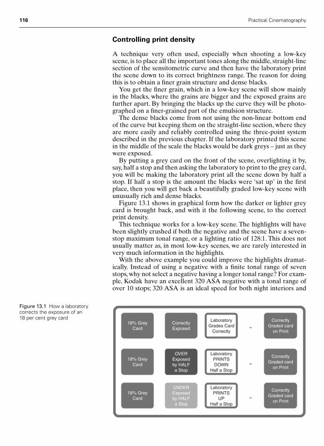
116 Practical Cinematography
Controlling print density
A technique very often used, especially when shooting a low-keyscene, is to place all the important tones along the middle, straight-linesection of the sensitometric curve and then have the laboratory printthe scene down to its correct brightness range. The reason for doingthis is to obtain a finer grain structure and dense blacks.
You get the finer grain, which in a low-key scene will show mainly in the blacks, where the grains are bigger and the exposed grains arefurther apart. By bringing the blacks up the curve they will be photo-graphed on a finer-grained part of the emulsion structure.
The dense blacks come from not using the non-linear bottom end of the curve but keeping them on the straight-line section, where theyare more easily and reliably controlled using the three-point systemdescribed in the previous chapter. If the laboratory printed this scenein the middle of the scale the blacks would be dark greys – just as theywere exposed.
By putting a grey card on the front of the scene, overlighting it by,say, half a stop and then asking the laboratory to print to the grey card,you will be making the laboratory print all the scene down by half astop. If half a stop is the amount the blacks were ‘sat up’ in the firstplace, then you will get back a beautifully graded low-key scene withunusually rich and dense blacks.
Figure 13.1 shows in graphical form how the darker or lighter greycard is brought back, and with it the following scene, to the correctprint density.
This technique works for a low-key scene. The highlights will havebeen slightly crushed if both the negative and the scene have a seven-stop maximum tonal range, or a lighting ratio of 128:1. This does notusually matter as, in most low-key scenes, we are rarely interested invery much information in the highlights.
With the above example you could improve the highlights dramat-ically. Instead of using a negative with a finite tonal range of sevenstops, why not select a negative having a longer tonal range? For exam-ple, Kodak have an excellent 320 ASA negative with a tonal range ofover 10 stops; 320 ASA is an ideal speed for both night interiors and
18% GreyCard
18% GreyCard
CorrectlyExposed
OVERExposedby HALFa Stop
�
�
�
LaboratoryPRINTSDOWN
Half a Stop
CorrectlyGraded card
on Print
CorrectlyGraded card
on Print
18% GreyCard
UNDERExposedby HALFa Stop
LaboratoryPRINTS
UPHalf a Stop
CorrectlyGraded card
on Print
LaboratoryGrades Card
Correctly
Figure 13.1 How a laboratorycorrects the exposure of an 18 per cent grey card
Chap-13 12/16/04 3:12 PM Page 116

Using the 18 per cent grey card 117
exteriors – it gives you the ability to print your work one and a half stopsup or down without coming off the straight-line section of the curve.
Shifting colour
The technique described above can also be used to shift the colourbalance of your final print.
Let us take an example where you wish to shoot an interior on loca-tion and there is a window in the back of the shot. Let us suppose youonly have tungsten lighting with you.Also, you want to keep the sceneoutside the window a little bright, say one stop, and a little cool, say by the equivalent of a half blue filter, a half CTB (colour tempera-ture blue).
The above decisions will lend a very pleasing exterior feel to thescene outside the window.
Now light the interior putting half CTB filters on your lamps. Thisgives you exactly the colour relationship you are looking for betweenthe interior and the exterior.The exterior is lit by daylight, which is theequivalent of full CTB, so you have your half blue difference betweeninterior and exterior.
Assuming that you have tungsten-balanced film in your camera, youwill need to correct the film to the interior lighting, which is half blue.The filter to use would be a Wratten 85C, but this will absorb half astop of light and you will already have lost a lot of exposure by puttingthe half CTB filters on your lamps.
An alternative solution is to use no filter at all on the camera to getthe desired effect. To do this, put the 18 per cent grey card into thebeam of one of your filtered lamps, take a reading with your spotmeter from the grey card and, using this exposure on the lens, run thecamera for 10 seconds. Now take a reading of the scene, put this expos-ure on the lens and shoot the scene.
If you tell the laboratory that you want the whole scene graded tothe grey card, they will have to remove the half blue you exposed thecard with and will also remove the same quantity of blue from the restof the scene. You will now have a print that is exactly the same as hadyou used a Wratten 85C, but you will not have had to sacrifice theexposure loss of the filter.
The above colour correction technique works for any colour so long asthere is sufficient range in the negative to accommodate the colour shift.
Intentional colour changes
If there is not sufficient range in the negative in the example aboveyou will get crushing in the extreme tones of the colour you haveshifted. This can, very occasionally, be to your advantage.
If you wish to desaturate a colour, say blue for an exterior scene, inorder to create a bleak feel to the piece, then you could shoot with ashort tonal range tungsten-balanced film, use no correction on thecamera and correctly expose the 18 per cent grey card using the ASArating of the film in tungsten light.
The blue layer will now have been overexposed relative to the redlayer of the emulsion. This will have crushed the red highlights andlifted the blue dark tones to paler tones – this we call desaturation.
Chap-13 12/16/04 3:12 PM Page 117

118 Practical Cinematography
When the laboratory prints the scene correctly to your 18 per centgrey card, this will cause crushing of the highlights and lifting of theshadows in the blue layer; this will remain since we chose a film with-out the latitude to cope with it. The middle densities will return to thecorrect position on the print’s sensitometric curve.
The above technique gives a very pleasing ‘gritty’ feel to a scene. Itis much more reliable than asking the laboratory to print for the effectif they have the 18 per cent grey card to work to all the time.They willproduce the same effect on each day’s rushes providing you rememberto put a card on before each scene and tell them that you want the following scenes graded to it.
Developments in grey cards
For many years, motion picture grey cards always came as a two-pagecard folder, as in Figure 13.2. One page has a series of progressive greypatches and the other page has a simple 18 per cent grey sheet. Thecustom, particularly when filming for television, was to photographboth pages simultaneously.
The grey card worked exactly as described above.The series of pro-gressively darker grey stripes was intended to be read by the telecineoperator as a stepped waveform. However, this did not really work. Apiece of card, however high the quality of the printing, will only reflectfrom the whitest patch to the darkest patch a maximum range of fourstops and that is if it is perfectly lit. Clearly, this is not even the tonalrange of the television system, so does not really tell the telecine oper-ator very much.
The 18 per cent grey card, on the other hand, is a universally, indeedinternationally, known standard and therefore can be used as a meansof communication between the cinematographer and the laboratoryno matter what countries either or both are in. It therefore became thenorm to photograph only the 18 per cent grey card and more or less fillthe frame with it.
When filming for television it has become more and more popularto transfer the negative directly to a videotape. This is increasinglybeing done at the rushes stage, even on feature films, so that thoserushes can be transferred directly into a non-linear computer editingsystem. It can also be a very high quality way of transferring a cut nega-tive to the final, graded transmission tape.
One problem with transferring the rushes negative directly to tape,without making a print, is that the cinematographer no longer gets thegrading lights that gave them an accurate guide to both the densityand colour balance of the previous day’s work (see Chapter 8 for a fulldescription of grading lights).
Kodak were very aware of this and have produced a very nearlyideal solution. They produced a very accurate and durable grey card(see Figure 13.3), on each side of which is a white and a black patch.Knowing that it is impossible to get pure white and black on paperthey set the very dark grey, masquerading as black, and the nearlypure white paper, trying to be pure white, at very consistent densities.They called this new card the ‘Grey Card Plus’.
The next step was to produce a clever box of electronics that wouldrecognize the signal associated with the image of this card and, if you
Figure 13.2 The traditional combined grey card
Figure 13.3 Kodak’s ‘Grey Card Plus’
Chap-13 12/16/04 3:12 PM Page 118

Using the 18 per cent grey card 119
so wished, automatically grade the following scenes to it. At the sametime, the machinery will log the grading in points very similar toprinter lights and can be asked to print this report to either a floppydisk or a hard-copy printer. The cinematographer can then receive areport from a direct negative-to-tape transfer, which is just as informa-tive as they used to get from the film grader.
I have gone over to using the Kodak 18 per cent grey card, whetherthe laboratory I happen to be using has the electronics or not, as it isby far the most accurate and consistent card I have come across.
If you acquire a Kodak card it comes with very good instructions onthe back so you can refresh your mind as to how to use it.
Conclusions
1 You can use an 18 per cent grey card to communicate your grad-ing wishes to the film laboratory.
2 You can control both the density and colour of the print or tapetransfer by using the card.
3 You must state your wish to grade to the grey card on the labora-tory report sheet.
4 Talk to your laboratory before you start shooting and tell themwhat you intend to do.
5 It is a good idea to put a message on the card itself to reinforce themessage – your laboratory will appreciate this.
Chap-13 12/16/04 3:12 PM Page 119

14
Colour temperature
What is colour temperature?
Colour temperature is important to the cinematographer for a num-ber of reasons. Technically, it is vital that any light source that is toappear neutral in the final rendition of the scene is emitting light of thesame colour balance as that for which the film has been designed.Artistically, it is important that the cinematographer has an under-standing of the psychological and emotional effects of the colour oflight within a scene and that they have complete control over this colour.
In order to evaluate and control anything, we must have a unit ofmeasurement and a means of measuring. We measure differences incolour temperature in degrees Kelvin (°K) using a colour temperaturemeter.
This unit of measurement is named after Lord William ThomsonKelvin, a British physicist who, at the end of the nineteenth century,developed a means of quantifying that which makes colours different.His experiment was quite simple. He took a beam of daylight comingthrough a hole in his shutters and caused it to pass through a simpleglass prism so as to form a rainbow effect on the opposite wall. Hethen placed a standard mercury thermometer in the path of each sep-arate colour and noted that the reading was very slightly different.Thus, he discovered the relationship between the colour of light andthe temperature that relates to it.
Kelvin did not leave his discovery there, but went on to propose thatif a black body, i.e. one having no reflective surfaces and which cantherefore only emit light, is heated to a glowing state then the lightcoming from it will have a different colour depending on the tempera-ture the body is heated to. The classic way to illustrate this is to imag-ine a poker being put into a fire. Initially, the poker is black iron, but asit warms it first glows deep red then a straw colour and as it becomeshotter still it appears white. If the fire were hot enough, say somethingakin to a blacksmith’s furnace, then eventually the iron would appearto be blue/white.
Here we must guard against a simple confusion. At lower tempera-tures the colour emitted by a heated black body is red and at highertemperatures blue, but we think of red as warm and blue as cold.
120
Chap-14 12/16/04 3:15 PM Page 120
Colour temperature 121
Our emotional reaction to colour comes from nature, where cold daysare thought of as lit by blue light, snow scenes for instance, but we reactto red scenes as warm, a room lit by a log fire for instance. So, rememberthe actual temperature required to achieve a given colour temperatureis the reverse of how we emotionally react to the colour of light emitted.
The colour temperature of a source is deemed to be the tempera-ture of the source in degrees Celsius plus 273°C, �273°C beingdefined as the temperature of absolute zero. In practice, we find thatthere are some slight changes, some physical and some due to thesource not being a black body. Therefore, a tungsten filament lamp will have a colour temperature approximately 50°K above the actualtemperature of the filament.
Filters and Mired shift values
In order to change the colour, and therefore the colour temperature,of a light source we usually put a filter in its path. A blue filter willcause the light passing through it to appear more blue, but it will alsoreduce the intensity, or amount of energy, of the light. This is becausedespite, occasionally, the evidence of our eyes, filters do not add colourbut can only absorb or subtract colour. A blue filter will therefore beabsorbing the wavelengths of red light in order to make the subsequentlight appear more blue. It does this by converting the light absorbedinto heat which, as we saw earlier, has a direct relationship to light,both being a vibrational energy. It is important to remember this, as it isone reason why gelatine filters on lamps first bleach out and eventuallyburn through.
In order to evaluate the effect of a filter, we must have some unitwith which to measure its effect. These are called Mired shift values.A Mired value is a mathematically more useful measurement for thispurpose than degrees Kelvin but still represents, albeit in a differentform, the colour temperature of light. A Mired shift value is thereforethe shift in the colour temperature of the light passing through it thatany given filter can cause to occur.
Before going any further, it should be understood that in practicalcinematography one never has to calculate the mathematics – onerefers to the tables or switches the colour temperature meter to give adirect read-out in shift values. The formulae are shown here as anexplanation of the cause and effect of the theory.
A Mired value can be expressed in the mathematical form:
A conversion table (Figure 14.1) shows at a glance the Mired valuesof colour temperatures from 2000 to 6900°K in steps of 100°K.
Certain filters have the ability to convert light from one colour tem-perature to another. The Mired shift value will be approximately thesame at any given starting value.Therefore, for a given filter, the changein colour temperature caused will be more or less the same if the sourceof light starts at 2000 or 6000°K.This makes choosing correction filtersvery simple.
Mired value1000 000
Colour temperature in de�
ggrees Kelvin
Chap-14 12/16/04 3:15 PM Page 121

122 Practical Cinematography
Each filter can therefore be categorized as having a particularMired shift value irrespective of the light source it is affecting.
The value of this Mired shift can be expressed as:
where T1 represents the colour temperature of the original lightsource and T2 represents the colour temperature of the light afterpassing through the filter.
The Mired shift value can be either positive or negative. If filtersdeal with changes in the blue or red part of the spectrum they arecalled light-balancing filters (LB filters). Brown or reddish filters, shownin the left-hand column of Figure 14.2, lower colour temperature butthe Mired value will, being a reciprocal function, be increased. Suchfilters, therefore, have a positive value. Bluish filters, shown in theright-hand column of Figure 14.2, have a negative value.
Filters that deal with green, or its complementary colour magenta,are known as colour-compensating filters (CC filters). They work inexactly the same way as light-balancing filters in that the value isalways added, allowing for its mathematical sign. Figure 14.3 showsthe shift and filter factors for CC filters.
Mired shift value10T
10T1
6 6
� �2
Figure 14.1 Mired values ofcolour temperature from2000 to 6900°K
°K 0 �100 �200 �300 �400 �500 �600 �700 �800 �900
2000 500 476 455 435 417 400 385 370 357 345
3000 333 323 312 303 294 286 278 270 263 256
4000 250 244 238 233 227 222 217 213 208 204
5000 200 196 192 189 185 182 179 175 172 169
6000 167 164 161 159 156 154 152 149 147 145
82 – �101⁄3
82A – �211⁄3
82B – �322⁄3
82C – �452⁄3
80D – �561⁄3
80C – �81 1
80B – �112 12⁄3
Figure 14.2 Mired shiftvalues of Wratten light-balancing or LB filters
81 – �91⁄3
81A – �181⁄3
81B – �271⁄3
81C – �351⁄3
81D – �422⁄3
81EF – �522⁄3
85C – �991⁄3
85 – �1122⁄3
85B – �1312⁄3
Filter Mired Filtershift factor
Filter Mired Filtershift factor
Positive – towards yellow Negative – towards blue
Chap-14 12/16/04 3:15 PM Page 122

Colour temperature 123
Colour-compensating filters have only a limited use in cinematog-raphy, as they are primarily available for fine-tuning colours in trans-parency or reversal work. They do come into their own, however,when a cinematographer has to work with available light from fluo-rescent tubes, which often have an excess of green light. This discrep-ancy can be corrected by putting the appropriate magenta filter,magenta being the complementary colour to green, over the tubes orin front of the lens if no other source of light is to be added.
Filters have another important value, their filter factor. This is alsoshown in the tables (Figures 14.2 and 14.3). The filter factor is alwaysexpressed as the part or whole of a stop on the lens and is expressed asa fraction of a real number or a real number plus a fraction.This is theamount that the lens must be opened up to allow for the amount oflight absorbed by the filter. Therefore, a filter factor of one-third willneed the aperture to be opened by one-third of a stop. Similarly, a filterfactor of two-thirds will need the lens aperture to be opened by two-thirds of a stop.
Here it is important to understand the difference in approach whenadding together Mired shift values and filter factors. If you put two fil-ters in front of the lens then you will combine their Mired shift values,taking regard of their mathematical sign. For example, combining twofilters having shift values of �35 and �10 will result in a combinedMired shift of �25. But if their filter factors, when expressed as f-stops,were one-third and one-third, then the combined filter factor will betwo-thirds and the lens must be opened up by two-thirds of a stop.Filter factors are always positive so are always added together.
In practice, it is usual to consider changes of 100°K or more as import-ant, as this is the smallest change the eye is likely to notice unless it ispossible, within the scene, to compare the sources – in which case dif-ferences down to as little as 20°K may be noticeable. This may occur,say, when a row of windows have one lamp each outside them, repre-senting sunlight. In this case, very accurate measurement and filtrationof the lamps will be required to get them all within a 20°K range.
The colour temperature meter
Colour temperature meters come in two basic forms, reading either twoor three colours.The two-colour meter reads only blue and red. It is notsophisticated enough for a working cinematographer but is useful forsetting filters on lamps, as this usually only concerns blue and red.
5 G – �21⁄3
10 G – �41⁄3
20 G – �71⁄3
30 G – �102⁄3
40 G – �132⁄3
Figure 14.3 Mired shiftvalues of Wratten colour-compensating or CC filters
5 M – �21⁄3
10 M – �41⁄3
20 M – �81⁄3
30 M – �132⁄3
40 M – �182⁄3
Filter Value Filterfactor
Filter Value Filterfactor
Positive – towards magenta Negative – towards green
Chap-14 12/16/04 3:15 PM Page 123
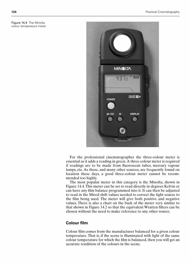
124 Practical Cinematography
For the professional cinematographer the three-colour meter isessential as it adds a reading in green.A three-colour meter is requiredif readings are to be made from fluorescent tubes, mercury vapourlamps, etc. As these, and many other sources, are frequently found onlocation these days, a good three-colour meter cannot be recom-mended too highly.
The most popular meter in this category is the Minolta, shown inFigure 14.4.This meter can be set to read directly in degrees Kelvin orcan have any film balance programmed into it. It can then be adjustedto read in the Mired shift values needed to correct the light source tothe film being used. The meter will give both positive and negative values. There is also a chart on the back of the meter very similar tothat shown in Figure 14.2 so that the equivalent Wratten filters can bechosen without the need to make reference to any other source.
Colour film
Colour film comes from the manufacturer balanced for a given colourtemperature. That is, if the scene is illuminated with light of the samecolour temperature for which the film is balanced, then you will get anaccurate rendition of the colours in the scene.
Figure 14.4 The Minoltacolour temperature meter
Chap-14 12/16/04 3:15 PM Page 124

Colour temperature 125
Normally, cinematograph film comes balanced for one of two colourtemperatures: tungsten light of 3200°K or nominal daylight of 5600°K.We say nominal daylight since, as you can see from Figure 14.5, day-light comes in many colour temperatures. However, 5600°K is theinternational standard all daylight films are balanced for.The standardof 5600°K is used because it represents a mixture of light from bluesky with some cloud scatter.
Figure 14.5 shows the colour temperatures of a number of knownlight sources.
It is interesting to note that a drop of one volt in the power supplyto a tungsten bulb will usually drop the colour temperature by approxi-mately 10°K.
For the cinematographer wishing to convincingly recreate daylight,it is important to understand that the different sources – direct sun,shadow and deep shadow – will all have different colour temperatures.There are a number of reasons why the different kinds of daylighthave different colour temperatures. Direct sunlight varies, mainly, dueto the amount of the Earth’s atmosphere it has to pass through and theamount of cloud in the sky. In the morning and afternoon the light hasto pass obliquely through the atmosphere, while at noon it is takingthe much shorter path directly from above. This, together with dra-matically varying amounts of water suspended in the air, will clearlychange the colour of the light passing through the atmosphere.
In the shadowed area, matters are different. If a reading is takenwith the meter turned directly away from the sun, but still in the sameplace as where the sunlight reading was taken, the light reaching themeter will be that reflected off the clouds and the atmosphere itself,and this will be bluer than the direct sunlight reading. In the deepshadow, there will be no direct sunlight and all the light will bereflected – it will therefore be bluer still. This is useful in that gettingthose colours right can give a powerful message to the audience as tothe time of day of the scene.
Figure 14.6 shows a number of readings that were taken in earlyAugust in London, when sunrise was 5.28 a.m. As you can see, the
Daylight sourcesCandle flame 1930°KDawn or dusk 2000°KAn hour after sunrise 3500°KEarly morning/late afternoon 4500°KAverage summer sunlight 5600°KSunlight from a blue/white sky 6500°KLight summer shade 7000°KOvercast sky 7000°KAverage summer shade 8000°KHazy sunlight 9000°KSummer sky up to 20 000°K
Artifical lightDomestic light bulb 2800°KPhotographic incandescent bulb 3200°KTungsten halogen bulb 3200°KPhotoflood 3400°K3200°K �1⁄4 blue filter 3600°K3200°K � 1⁄2 blue filter 4100°K3200°K � full blue filter 5650°KHMI, CID and MSR lamps – approximately 5600°K
Figure 14.5 The colourtemperatures of various lightsources
Chap-14 12/16/04 3:15 PM Page 125
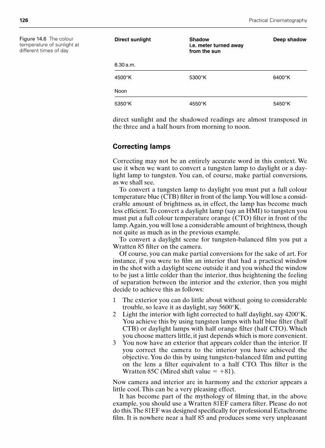
126 Practical Cinematography
direct sunlight and the shadowed readings are almost transposed inthe three and a half hours from morning to noon.
Correcting lamps
Correcting may not be an entirely accurate word in this context. Weuse it when we want to convert a tungsten lamp to daylight or a day-light lamp to tungsten. You can, of course, make partial conversions,as we shall see.
To convert a tungsten lamp to daylight you must put a full colourtemperature blue (CTB) filter in front of the lamp.You will lose a consid-erable amount of brightness as, in effect, the lamp has become muchless efficient.To convert a daylight lamp (say an HMI) to tungsten youmust put a full colour temperature orange (CTO) filter in front of thelamp.Again, you will lose a considerable amount of brightness, thoughnot quite as much as in the previous example.
To convert a daylight scene for tungsten-balanced film you put aWratten 85 filter on the camera.
Of course, you can make partial conversions for the sake of art. Forinstance, if you were to film an interior that had a practical window in the shot with a daylight scene outside it and you wished the windowto be just a little colder than the interior, thus heightening the feelingof separation between the interior and the exterior, then you mightdecide to achieve this as follows:
1 The exterior you can do little about without going to considerabletrouble, so leave it as daylight, say 5600°K.
2 Light the interior with light corrected to half daylight, say 4200°K.You achieve this by using tungsten lamps with half blue filter (halfCTB) or daylight lamps with half orange filter (half CTO). Whichyou choose matters little, it just depends which is more convenient.
3 You now have an exterior that appears colder than the interior. Ifyou correct the camera to the interior you have achieved theobjective. You do this by using tungsten-balanced film and puttingon the lens a filter equivalent to a half CTO. This filter is theWratten 85C (Mired shift value � �81).
Now camera and interior are in harmony and the exterior appears alittle cool. This can be a very pleasing effect.
It has become part of the mythology of filming that, in the aboveexample, you should use a Wratten 81EF camera filter. Please do notdo this.The 81EF was designed specifically for professional Ectachromefilm. It is nowhere near a half 85 and produces some very unpleasant
Direct sunlight Shadow Deep shadowi.e. meter turned awayfrom the sun
8.30 a.m.
4500°K 5300°K 6400°K
Noon
5350°K 4550°K 5450°K
Figure 14.6 The colourtemperature of sunlight atdifferent times of day
Chap-14 12/16/04 3:15 PM Page 126

effects when used with colour negative. One such effect is to accentu-ate the veins in a person’s face and make them look as if they are aheavy beer-drinker. The difference between a Wratten 81EF and aWratten 85 is a Mired shift of �60.
If you were shooting the above scene from the outside and wantedto make the interior look cosy and warm, then leave the lightingexactly as it is and correct the camera to full daylight. If you are stay-ing with the tungsten-balanced film, then simply change the camera filter to a Wratten 85 or change the film to one already balanced fordaylight. The exterior will now be colour correct and the interior willbe warm and inviting.
Quarter blues (quarter CTB) are often used on backlights toincrease the feeling of separation of foreground to background.
Night exteriors are often shot using tungsten film with full or halfblue lamps. Full blue is often described (usually by those that don’tlike the effect) as American moonlight, as distinct from Americannight, which is what they call day-for-night in France. This comes fromits perhaps being overused, to European eyes, in some American films.There is good logic behind full blue, though.
What is moonlight? It is sunlight bounced off the moon and themoon is colourless or at most pale grey. The light leaving the moonafter it has been bounced off will have reduced in brightness, but it willnot have had its colour temperature changed in any dramatic way.When it arrives on Earth it will still be the full blue of pure sunlight bycomparison with our tungsten foreground and film.
You must make the artistic decision how blue you want your moon-light to be, but there is no getting away from it – real moonlight isroughly the same colour temperature as daylight.
Colour temperature 127
Chap-14 12/16/04 3:15 PM Page 127

15
Camera filters
We use filters in cinematography to alter the image either for technicalreasons to correct the colour of the light to that required by the filmwe are using, or because we may wish to change the image in someway that will enhance our storytelling powers.The former is often neces-sary, the latter much more fun.
The majority of coloured filters are known by numbers or a combin-ation of numbers and letters – for instance, 85 and 85B. These are sim-ply the catalogue number they are to be found under in the EastmanKodak Wratten Filter Catalogue. All filter manufacturers will use theWratten filter numbers for their version of the filter in their list thatconforms to the transmission characteristics of the filter in the Wrattenlist.A Wratten catalogue complete with transmission graphs can be anilluminating read once you know how to interpret the information.
Effects filters are usually described by some term that indicateswhat change they will make to the image – for example, fog filter.
Colour-compensating filters
Colour-compensating filters, or CC filters, are carefully stepped filters inthe primary colours or their reciprocal colour. They are used, in frontof the lens, to correct the source light to the film in use. They come insmall steps so you need a lot of them to be able to cope with any situ-ation. In reality, we rarely use CC filters in cinematography – they aremainly used in still photography to obtain an accurate original trans-parency, as with the reversal process there can be no correction later.
Colour-correction filters
This phrase usually refers to filters used to correct a daylight scenewhen shooting with tungsten-balanced film. The usual full correctionfilter is the Wratten 85. The various alternatives are:
Wratten 85 Full correction85B Full correction � slight warming – often used as
standard correction when filming for telecine, as this can enhance the transfer to tape
128
Chap-15 12/16/04 3:16 PM Page 128
Camera filters 129
85C Half the correction of the straight 85 – often used when interior is lit to the same colour balance, so that any exterior, say through a window, appears slightly cold.
All these filters also come with a neutral density built into them. Forthe 85 these are available as 85BN3, 85BN6 and 85BN9. Each unit of 3stands for a density of 0.3, which exactly halves the light passing throughthe filter. Therefore, an 85BN3 reduces the exposure by an extra stopin addition to the two-thirds of a stop correction needed for thestraight 85. Likewise, the 85BN6 reduces the exposure by two stopsand the 85BN9 by three stops, again in addition to the straight 85.
Skin tone warmer
A Tiffen 812 is very effective in warming up skin tone while having anegligible effect on the other colours in the scene. This is particularlyuseful for a close-up on a cold day.
Sepia, coral, colour effects, etc.
Just as you would expect from their names, these filters lend an over-all colour tint to the scene. Sepia and coral do to the film roughly whatyou will see in the viewfinder, but some of the more esoteric filters, saytobacco, whisky, suede, etc., can come out on film a little differentlythan they look to the naked eye. Coloured filters often absorb quite alot of light to perform their trick. If you intend to use the heavier filtersI strongly recommend you shoot a test under identical lighting beforecommencing your principal photography – this is not to say that theycannot be very effective, it is just rather surprising to find exactly whatthey do sometimes.
Graduated filters
Grads, as they are always known, are usually coloured or neutral densityfilters. They are used to colour, or darken, one part of a scene withoutaffecting the rest of the scene.
If, for instance, you were using a neutral density grad to attenuate asky that was too bright, then you would need a filter taller than theactual frame size so that you would have enough to slide up and downin order to place the edge of the grad accurately on the skyline. If yourstandard filter size was 4 in. � 4 in., then you would order your gradsin 4 in. � 6 in.A 0.6 (i.e. two stops) neutral density grad is probably themost useful – I always carry one. Grads can be ordered with either a‘hard’ or a ‘soft’ edge. I find soft-edged grads are usually the more suc-cessful. They are usually supplied where the maximum density of thefilter is either 0.3, 0.6 or 0.9. The lighter one would, for instance, bereferred to as a point three ND grad.
Coloured grads are used less often than simple ND grads. I carry afull set of coral grads and a few blue grads.With these I can turn almostany time of day into early morning or sunset, with both effects availablein a cool or warm version. The joy of using them is that what you see
Chap-15 12/16/04 3:16 PM Page 129

130 Practical Cinematography
in the viewfinder is near enough what you will get on film, assumingyou judge the exposure correctly. If you are worried about setting theexposure, either swing the matte box away or take it off and, using aspot meter, take a reading through the filters as you have set them.
Neutral density filters
Neutral density filters are used to open up the aperture at which youwill shoot the scene.This may be because you wish to reduce the depthof field for dramatic reasons or simply to improve the definition of thelens. Most cinematic lenses work best between T5.6 and T8, thoughthese days it is nothing like as critical as it used to be if using modernlenses.The most common ND filters, as they are always referred to, arethe 0.3,0.6 and 0.9 NDs,where a density of 0.3 exactly halves the amountof light entering the lens and therefore you must open up one stop forevery 0.3 of density you have added to the front of the lens.
Low contrast filters
Low contrast filters, as you would expect, reduce the overall contrastof the scene. They do this by bleeding some of the light from the high-light parts of the scene into the shadows and thus lightening them.Theyusually come in a set of five filters, simply marked LC1, LC2, LC3, LC4and LC5.
The light LC filters are also useful in certain situations for creatinga more flattering close-up (see the section on ‘Matching shots’ later inthis chapter). Beware though, if you use too strong an LC filter you willget a veiling or milky look to the image.
Ultra contrast filters
Ultra contrast filters are similar to low contrast in that they will bleedhighlights into shadows, but they will not cause halation or flaringaround light sources or spectral highlights as will an LC filter. Theyalso reduce the definition far less than a low contrast filter. The LC fil-ter works with light in the image area – the ultra contrast filter worksmore with the incident, ambient light. They come in a range of eightfilters marked 1⁄8, 1⁄4, 1⁄2, 1, 2, 3, 4 and 5.They are very good at bringing upshadow detail when used with a video camera; I have achieved quitespectacular improvements to the shadows when using these filters on aSony DVW 790 camera. The same has proved true when I have shotusing HD (High Definition) with both the Sony HDW 900 and theHDW 750.
Fog filters
Fog, in reality, is caused by water droplets suspended in the atmos-phere. This causes the image to be degraded more and more the fur-ther away from camera the subject is. This is simply because it hasmore water to penetrate. Fog filters attempt to emulate this effect.
Chap-15 12/16/04 3:16 PM Page 130
Camera filters 131
The lighter filters reduce both contrast and definition.The heavier filtersmake things go rather fuzzy so do not, to my eye, reproduce the effectof nature very well.
Double fog filters
Double fogs affect flare and definition far less than standard fog filterswhile having a more pronounced effect on the contrast range of theimage. It is claimed that objects near to the camera will appear lessaffected than those further away – I’m not entirely convinced.
Pro-mist filters
Clear or ‘Classic’ pro-mist filters give a glow or halation aroundintense sources of light that are in shot. They do this without reducingthe contrast range as much as you might expect. Highlights become‘pearlized’.
Black pro-mists cause far less halation around highlights and pro-duce deeper, and some say more romantic, shadow tones.
If you like their effects, then which you use is entirely a matter oftaste. I much prefer ‘Classic’ pro-mists but I think, perhaps, I am in aminority here.
Both kinds of pro-mists are excellent on 16 mm as they do notreduce the definition as much as most of the other diffusion filters. On35 mm the lighter grades are used to reduce what is often seen as theexcessive contrast and acutance of modern film stocks and lenses.They come in a set of eight filters marked 1⁄8, 1⁄4, 1⁄2, 1, 2, 3, 4 and 5.
Star filters
Beware the use of star filters – they can make things look like a poorversion of a pop promo. They now come in a bewildering number ofversions – Vector, Hyper, North, Hollywood, etc. Most also come invarious numbers of points and widths between the lines on the filterthat create the star effect.
I rarely use any but a four-point 2 mm star filter.This is the only oneI carry in my own filter kit; anything else I so rarely use that I hire it in.
Star filters also add a small amount of diffusion.
Nets
Nets have different effects depending on their colour.A white net willtend to diffuse the highlights into the shadows, thus softening the con-trast and making the scene higher key. Dark nets will often bleedshadows into highlights. Both will tend to take some of the colour withthem. Brown nets can add a wonderful romantic look to a scene. Youwill need to style your lighting somewhat to suit the net you are using,especially if you have chosen a strong one.
It is not unusual for a cinematographer to put a fine net on the backof a zoom lens when shooting in 35 mm.The advantage here is that the
Chap-15 12/16/04 3:16 PM Page 131

132 Practical Cinematography
effect remains more or less the same at all the focal lengths of thezoom, whereas in front of prime lenses the effect is different on differ-ing focal lengths. This is mainly due to the variation in the amount ofphysical net in the optical path. I cannot recommend this trick for16 mm, as the diffusion created, even with the finest net, destroys thedefinition of the image far more than is usually acceptable.
Be very careful that the net put in front of the lens does not becomesharp enough to give you a pattern on the scene. This is a particularproblem with 16 mm and short-focal-length lenses. It will becomeimmediately apparent the moment you move the camera.
Nets will lend their own colour to a scene – a brown net will add anoverall warmth and richness to the tones, for instance, the darker netsadding more to the shadows and the lighter nets to the highlights. Netswill also give a slight star effect to point sources. A candle flame shotwith a black net can look very attractive and ‘Christmassy’.
Matching shots
You need to be very careful when using different focal length lensesduring a scene on which you are using diffusion filters. Longer focallengths will usually need less diffusion than shorter lengths. Fortunately,these things are fairly WYSIWYG (what you see is what you get), butyou have to look through with the stop on – it makes a difference.
Enhancing filters
These are very unusual filters that bring out, or accentuate, just onecolour without affecting any of the others. They come in all the pri-mary colours, though red is for some reason the most used. Both Tiffenand Hoya produce excellent enhancement filters. If you are to photo-graph a commercial with a red car as the product, do not leave homewithout a red enhancer – it will bring the car forward a treat.
Fluorescent light correction
The FLB filter corrects fluorescent light to type B film, i.e. tungsten-balanced, and FLD corrects fluorescent light to daylight film. Withmodern negative emulsions they are hardly necessary for cinematog-raphy, as the tubes are so much better these days and the processinglaboratories have so much more experience in printing scenes shotunder this lighting. Remember that if you can light all the set with fluor-escent light the laboratory correction will be most successful. Mixedlight is a nightmare.
Polar screens
Polar screens are used to darken the blue portion of a sky in colourphotography as well as reducing unwanted reflections in particularparts of a scene. The classic use is to make the colour of a car moresolid by reducing unwanted glare in the paintwork.
Chap-15 12/16/04 3:16 PM Page 132

They are only fully effective when rotated for best effect – if thesubject moves, say our car, then the effect will change as the relation-ship of the planes of the car change relative to both the direction ofthe lighting and the camera. This is also true if you pan across a bluesky – its blueness will alter depending on its relative angle to the Sun.
Polar filters reduce the exposure by one and a half to two stops. It isoften best to take a reading through the polarizing filter with yourexposure meter, but remember to have the filter at the same angle infront of the meter as you will place it on the camera, since the rotationof the polar filter will alter its absorption.
Filter factors
Filter factors are referred to as a simple whole number where a filterfactor of 2 equals a correction of one stop of aperture. Likewise, a fac-tor of 3 equals one and a half stops’ correction and 4 equals two stops.If in any doubt, measure the filter through your meter but rememberto point it at the same colour light under which you will be photo-graphing the scene.
The pan glass or viewing glass
This is not strictly a camera filter but the piece of glass, in a holder,often worn around the DP’s neck.These days it is not a pan glass at all,but its origins are so strong that the name is now synonymous withthat little viewing filter and the name seems impossible to kill off. Itmust be said that this filter is often worn, yes by me included, as a kindof chain of office so that everyone on the set will know who is the DP.
In the days when all films were made in black and white, it was quitehard to visualize the scene before the camera, which was of course in colour, as it might be seen on a cinema screen in black and white.Early black and white film was orthochromatic (ortho � singular,chromatic � colour), meaning it was incapable of recording black andwhite densities as a true representation of the colour brightness. In fact,the film was sensitive mainly to blue light, which then required verypeculiar make-up, ladies’ faces being painted yellow and their lips black.
Black and white film stocks developed into what became known aspanchromatic emulsions (pan � many). These emulsions were muchmore true in their rendition of colour brightness, as they could recordsome red and green.
Cinematographers who were used to orthochromatic film emul-sions had considerable difficulty in imagining the tones that would berecorded on the new emulsions.The solution was to produce a viewingfilter that the DP could look through that would, to the eye, give a fairrepresentation of the scene as it would be recorded on the newpanchromatic film. Hence the new viewing filter became known as apanchromatic viewing filter – or a pan glass.
As black and white technology progressed, various viewing filterswere developed and matching pairs were sometimes available for work-ing under daylight and tungsten light.
Nowadays, the viewing filters should strictly be called colour viewingfilters, for they all try and show you the scene, not as black and white,
Camera filters 133
Chap-15 12/16/04 3:16 PM Page 133
but in colour with the tone scale modified to match the tonal scale ofmodern colour emulsions.
If one is honest, the most common use of a modern pan glass is tolook at the clouds in the sky to see if one can get a matching lightingstate from the previous shot. Many DPs still judge their lighting bythem as, particularly when using a camera operator looking down theviewfinder may be inconvenient, a colour viewing filter can be a greathelp in judging the lighting ratio of a scene.
A good gaffer will do the sky watch for you. My gaffer hasdeveloped an uncanny ability to guess a cloud’s progress across thesky. He might use his pan glass or a gaffer’s viewing filter I found forhim. This is incredibly dark and green, as this is the safest colour tolook at the sun with, though he reluctantly admits that in the UK it’s abit too dark – hence he is always asking me when we are going to getthat picture in California so that he can make proper use of the glass I gave him!
134 Practical Cinematography
Chap-15 12/16/04 3:16 PM Page 134

16
Depth of field
The depth of field is the distance between the nearest and the farthestsubjects from the lens that will appear to look sharp. ‘Appear to’ is themost important part of that sentence, because in a technical sense onlyan image that is exactly at the distance the lens is focused at will be infocus at the film plane. But, when can the audience discern if an imageis, to them, sharp or not?
When an image is shown on the screen, the near and far objects thatappear to be in focus do so because the human eye has a limit to itsresolving power.Any image we see at this resolution, or better, we willconsider to be sharp. The extremes of the depth of field are the pointsat which the resolution of the eye has been reached.
Depth of focus
There is often confusion between the terms depth of field and depth offocus. Depth of field refers to the image in front of the lens, and maybe thought of as relating to the field of view. Depth of focus refers tothe elements in focus behind the lens at the plane of focus. They mustnot be confused.
Circles of confusion
At the moment of exposure the cinematographer or, more likely, thefocus puller must be certain which parts of the scene will be sharp. Wetherefore need some way of measuring the sharpness of the image onthe film relative to the limit of the eye’s resolution at the time of view-ing. Suppose an image is photographed on 35 mm film and shown in alarge theatre (see Figure 16.1), and we assume our audience is one-third of the way back from the screen and we know that the eye’s max-imum resolving power is usually considered to be one minute of arc.We can now work out the size of the smallest dot on the screen thatthe eye can see in perfect focus. We can then measure the distance ofour audience from the screen and, by applying a little trigonometry tothis distance and our one minute of arc, come up with a physical
135
Chap-16 2/8/05 11:25 AM Page 135
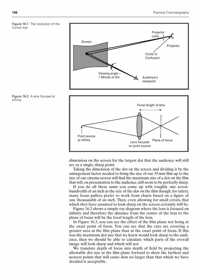
136 Practical Cinematography
dimension on the screen for the largest dot that the audience will stillsee as a single, sharp point.
Taking the dimension of the dot on the screen and dividing it by theenlargement factor needed to bring the size of our 35 mm film up to thesize of our cinema screen will find the maximum size of a dot on the filmthat will,on presentation to the audience, still seem to be perfectly sharp.
If you do all these sums you come up with roughly one seven-hundredth of an inch as the size of the dot on the film though, for safety,many focus pullers prefer to work from charts based on a figure of one thousandth of an inch. Then, even allowing for small errors, thatwhich they have assumed to look sharp on the screen certainly will be.
Figure 16.2 shows a simple ray diagram where the lens is focused oninfinity and therefore the distance from the centre of the lens to theplane of focus will be the focal length of the lens.
In Figure 16.3, you can see the effect of the film plane not being atthe exact point of focus. You can see that the rays are covering agreater area at the film plane than at the exact point of focus. If thiswas the maximum dot size that we knew would look sharp to the audi-ence, then we should be able to calculate which parts of the overallimage will look sharp and which will not.
We translate depth of focus into depth of field by projecting theallowable dot size at the film plane forward to show the farthest andnearest points that will cause dots no larger than that which we havedecided is acceptable.
Screen
ProjectorLens
Projector
Circle ofConfusion
Audience’sviewpoint
Viewing angle –1 Minute of Arc
Figure 16.1 The resolution of thehuman eye
Focal length of lens
Plane of focusLens focusedon point source
Point sourceat infinity
Figure 16.2 A lens focused atinfinity
Chap-16 2/8/05 11:25 AM Page 136
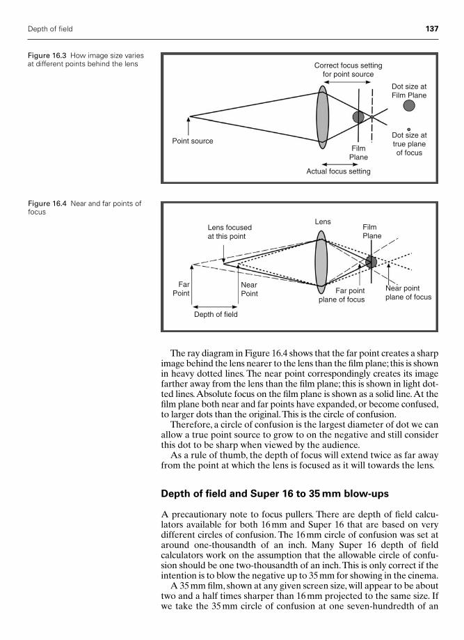
Depth of field 137
The ray diagram in Figure 16.4 shows that the far point creates a sharpimage behind the lens nearer to the lens than the film plane; this is shownin heavy dotted lines. The near point correspondingly creates its imagefarther away from the lens than the film plane; this is shown in light dot-ted lines.Absolute focus on the film plane is shown as a solid line.At thefilm plane both near and far points have expanded, or become confused,to larger dots than the original.This is the circle of confusion.
Therefore, a circle of confusion is the largest diameter of dot we canallow a true point source to grow to on the negative and still considerthis dot to be sharp when viewed by the audience.
As a rule of thumb, the depth of focus will extend twice as far awayfrom the point at which the lens is focused as it will towards the lens.
Depth of field and Super 16 to 35 mm blow-ups
A precautionary note to focus pullers. There are depth of field calcu-lators available for both 16 mm and Super 16 that are based on very different circles of confusion. The 16 mm circle of confusion was set ataround one-thousandth of an inch. Many Super 16 depth of field calculators work on the assumption that the allowable circle of confu-sion should be one two-thousandth of an inch.This is only correct if theintention is to blow the negative up to 35 mm for showing in the cinema.
A 35 mm film, shown at any given screen size, will appear to be abouttwo and a half times sharper than 16 mm projected to the same size. Ifwe take the 35 mm circle of confusion at one seven-hundredth of an
Correct focus settingfor point source
Dot size atFilm Plane
Dot size attrue planeof focus
FilmPlane
Actual focus setting
Point source
Figure 16.3 How image size variesat different points behind the lens
Lens focusedat this point
LensFilmPlane
NearPoint Far point
plane of focus
Near pointplane of focus
Depth of field
FarPoint
Figure 16.4 Near and far points offocus
Chap-16 2/8/05 11:25 AM Page 137
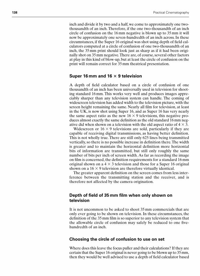
inch and divide it by two and a half, we come to approximately one two-thousandth of an inch. Therefore, if the one two-thousandth of an inchcircle of confusion on the 16 mm negative is blown up to 35 mm it willnow be approximately one seven-hundredth of an inch across. In thesecircumstances, if the Super 16 original was shot using depth of field cal-culators computed at a circle of confusion of one two-thousandth of aninch, the 35 mm print should look just as sharp as if it had been origi-nally shot on 35 mm negative.There are, of course, several other factorsat play in this kind of blow-up, but at least the circle of confusion on theprint will remain correct for 35 mm theatrical presentation.
Super 16 mm and 16 � 9 television
A depth of field calculator based on a circle of confusion of one thousandth of an inch has been universally used in television for shoot-ing standard 16 mm. This works very well and produces images appre-ciably sharper than any television system can handle. The coming ofwidescreen television has added width to the television picture, with thescreen height remaining the same. Nearly all film for television, at leastin the UK, is now shot using Super 16, and as Super 16 has very nearlythe same aspect ratio as the new 16 � 9 televisions, this negative pro-duces almost exactly the same definition as the old standard 16 mm neg-ative did when shown on a television with the old aspect ratio of 4 � 3.
Widescreen or 16 � 9 televisions are sold, particularly if they arecapable of receiving digital transmissions, as having better definition.This is not wholly true. There are still only 625 lines being transmittedvertically, so there is no possible increase in definition there.The widthis greater and to maintain the horizontal definition more horizontalbits of information are transmitted, but still only roughly the samenumber of bits per inch of screen width. As far as recording the imageon film is concerned, the definition requirements for a standard 16 mmoriginal shown on a 4 � 3 television and those for a Super 16 originalshown on a 16 � 9 television are therefore virtually identical.
The greater apparent definition on the screen comes from less inter-ference between the transmitting station and the receiver, and istherefore not affected by the camera origination.
Depth of field of 35 mm film when only shown on
television
It is not uncommon to be asked to shoot 35 mm commercials that areonly ever going to be shown on television. In these circumstances, thedefinition of the 35 mm film is so superior to any television system thatthe allowable circle of confusion may safely be reduced to one five-hundredth of an inch.
Choosing the circle of confusion to use on set
Where does this leave the focus puller and their calculations? If they arecertain that the Super 16 original is never going to be blown up to 35 mm,then they would be well advised to use a depth of field calculator based
138 Practical Cinematography
Chap-16 2/8/05 11:25 AM Page 138
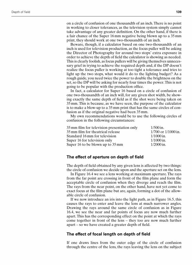
Depth of field 139
on a circle of confusion of one thousandth of an inch.There is no pointin working to closer tolerances, as the television system simply cannottake advantage of any greater definition. On the other hand, if there isa fair chance of the Super 16 mm negative being blown up to a 35 mmprint, they should work at one two-thousandth of an inch.
Beware, though, if a calculator based on one two-thousandth of aninch is used for television production, as the focus puller will be askingthe Director of Photography for around two stops’ extra exposure inorder to achieve the depth of field the calculator is showing as needed.This is clearly foolish, as focus pullers will be giving themselves unneces-sary grief in trying to achieve the required depth and, if the DP doesn’trealize the focus puller is working at too tight a tolerance and tries tolight up the two stops, what would it do to the lighting budget? As arough guide, you need twice the power to double the brightness on theset, so the DP will be asking for nearly four times the power.This is notgoing to be popular with the production office.
In fact, a calculator for Super 16 based on a circle of confusion ofone two-thousandth of an inch will, for any given shot width, be show-ing exactly the same depth of field as if the shot were being taken on35 mm. This is because, as we have seen, the purpose of the calculatoris to make a blow-up to a 35 mm print that has the same circles of con-fusion as if the original negative had been 35 mm.
My own recommendations would be to use the following circles ofconfusion in the following circumstances:
35 mm film for television presentation only 1/500 in.35 mm film for theatrical release 1/700 or 1/1000 in.Standard 16 mm for television 1/1000 in.Super 16 for television only 1/1000 in.Super 16 to be blown up to 35 mm 1/2000 in.
The effect of aperture on depth of field
The depth of field obtained by any given lens is affected by two things:the circle of confusion we decide upon and the aperture set on the lens.
In Figure 16.4 we see a lens working at maximum aperture.The raysfrom the far point are crossing in front of the film plane and form theacceptable circle of confusion when they diverge and reach the film.The rays from the near point, on the other hand, have not yet come toexact focus at the film plane but are, again, forming a dot of the allow-able circle of confusion.
If we now introduce an iris into the light path, as in Figure 16.5, thiscauses the rays to enter and leave the lens at much narrower angles.Drawing the rays around the same circle of confusion as in Figure16.4, we see the near and far points of focus are now much furtherapart. This has the corresponding effect on the point at which the rayscome together in front of the lens – they too are now much furtherapart – so we have created a greater depth of field.
The effect of focal length on depth of field
If one draws lines from the outer edge of the circle of confusionthrough the centre of the lens, the rays leaving the lens on the subject
Chap-16 2/8/05 11:25 AM Page 139

140 Practical Cinematography
side will show the largest object, at any given distance, that we canconsider will be recorded as the equivalent of a point source. Figure16.6 illustrates this.Any rays that were to stray outside that path wouldcreate an image larger than the circle of confusion and therefore wewould consider them not to be sharp.
It should be remembered that an aperture should be written down as,say, f4 or f/4. This represents a fraction, where f is the focal length of thelens and the figure underneath the bar is the aperture we are to set on thelens.This derives from the way aperture control came about. In order tocontrol the amount of light entering the lens, and therefore the exposure,early photographers would put on a lens cap with a hole in it smaller thanthe diameter of the lens.They quickly realized that they needed a way ofgetting the same exposure on several lenses of differing focal lengths. Itwas discovered that if one took a figure, say 4,and divided it into the focallength of the lens and then used the result as the diameter of the hole inthe lens cap of each lens, the exposure would be the same.
So, for a 100 mm lens, an aperture of 4 would need a hole 25 mm indiameter, as 100/4 � 25. To get the same exposure on a 10 mm lens,one divides 10 by 4 and uses a 2.5 mm hole.
If we consider a fairly normal motion picture lens having a focallength of 50 mm and an aperture of f2, given that we have decided onthe size of our circle of confusion, we can work out the depth of field.Aswe have seen, the diameter of the lens, or its stop, will be 50/2 � 25 mm.
Figure 16.7 represents such a 50 mm f2 lens. The short dotted linesrepresent the rays that will cross between the film plane and the lensand go out to form the farthest point of the depth of field. Objects only
Lens focusedat this point
Iris Lens FilmPlane
Near pointplane of focus
Far pointplane of focus
NearPoint
Depth of field
FarPoint
Figure 16.5 How an iris changesthe depth of field
Lens FilmPlane
Figure 16.6 A circle of confusionextrapolated in front of a lens
Chap-16 2/8/05 11:25 AM Page 140
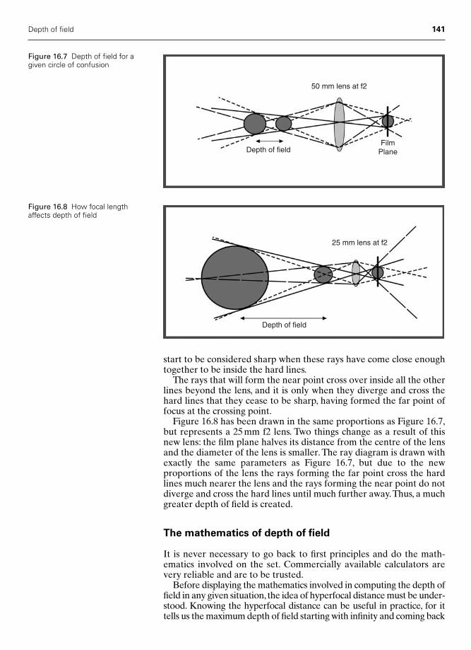
Depth of field 141
start to be considered sharp when these rays have come close enoughtogether to be inside the hard lines.
The rays that will form the near point cross over inside all the otherlines beyond the lens, and it is only when they diverge and cross thehard lines that they cease to be sharp, having formed the far point offocus at the crossing point.
Figure 16.8 has been drawn in the same proportions as Figure 16.7,but represents a 25 mm f2 lens. Two things change as a result of thisnew lens: the film plane halves its distance from the centre of the lensand the diameter of the lens is smaller. The ray diagram is drawn withexactly the same parameters as Figure 16.7, but due to the new proportions of the lens the rays forming the far point cross the hardlines much nearer the lens and the rays forming the near point do notdiverge and cross the hard lines until much further away.Thus, a muchgreater depth of field is created.
The mathematics of depth of field
It is never necessary to go back to first principles and do the math-ematics involved on the set. Commercially available calculators arevery reliable and are to be trusted.
Before displaying the mathematics involved in computing the depth offield in any given situation, the idea of hyperfocal distance must be under-stood. Knowing the hyperfocal distance can be useful in practice, for ittells us the maximum depth of field starting with infinity and coming back
50 mm lens at f2
Depth of fieldFilm
Plane
Figure 16.7 Depth of field for agiven circle of confusion
25 mm lens at f2
Depth of field
Figure 16.8 How focal lengthaffects depth of field
Chap-16 2/8/05 11:25 AM Page 141
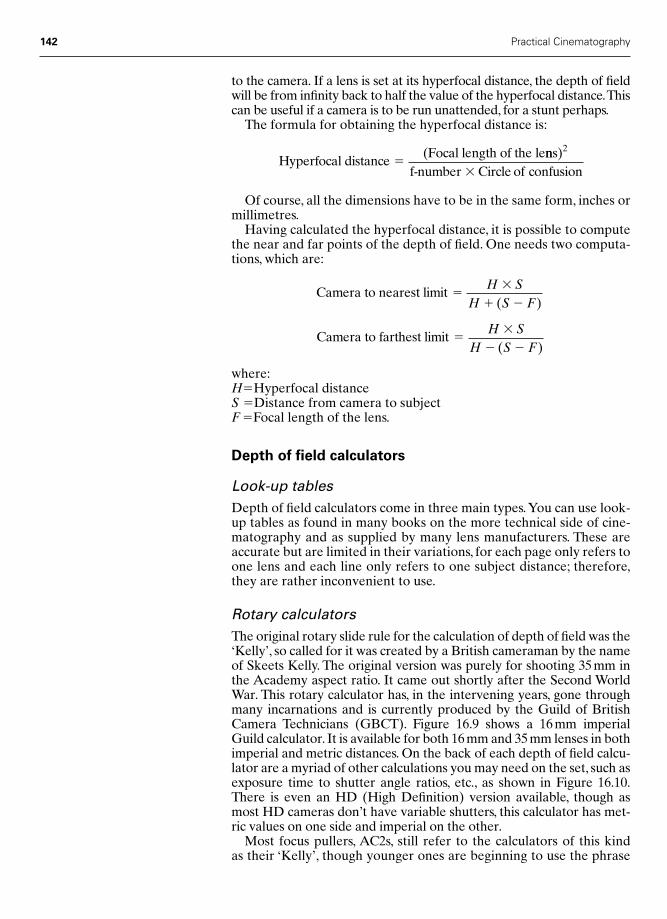
142 Practical Cinematography
to the camera. If a lens is set at its hyperfocal distance, the depth of fieldwill be from infinity back to half the value of the hyperfocal distance.Thiscan be useful if a camera is to be run unattended, for a stunt perhaps.
The formula for obtaining the hyperfocal distance is:
Of course, all the dimensions have to be in the same form, inches ormillimetres.
Having calculated the hyperfocal distance, it is possible to computethe near and far points of the depth of field. One needs two computa-tions, which are:
where:H�Hyperfocal distanceS �Distance from camera to subjectF �Focal length of the lens.
Depth of field calculators
Look-up tablesDepth of field calculators come in three main types.You can use look-up tables as found in many books on the more technical side of cine-matography and as supplied by many lens manufacturers. These areaccurate but are limited in their variations, for each page only refers toone lens and each line only refers to one subject distance; therefore,they are rather inconvenient to use.
Rotary calculatorsThe original rotary slide rule for the calculation of depth of field was the‘Kelly’, so called for it was created by a British cameraman by the nameof Skeets Kelly. The original version was purely for shooting 35 mm inthe Academy aspect ratio. It came out shortly after the Second WorldWar. This rotary calculator has, in the intervening years, gone throughmany incarnations and is currently produced by the Guild of BritishCamera Technicians (GBCT). Figure 16.9 shows a 16 mm imperialGuild calculator. It is available for both 16 mm and 35 mm lenses in bothimperial and metric distances. On the back of each depth of field calcu-lator are a myriad of other calculations you may need on the set, such asexposure time to shutter angle ratios, etc., as shown in Figure 16.10.There is even an HD (High Definition) version available, though asmost HD cameras don’t have variable shutters, this calculator has met-ric values on one side and imperial on the other.
Most focus pullers, AC2s, still refer to the calculators of this kind as their ‘Kelly’, though younger ones are beginning to use the phrase
Camera to farthest limit ��
� �
H SH S F( )
Camera to nearest limit ��
� �
H SH S F( )
Hyperfocal distance(Focal length of the le
�nns)
f-number
2
� Circle of confusion
Chap-16 2/8/05 11:25 AM Page 142
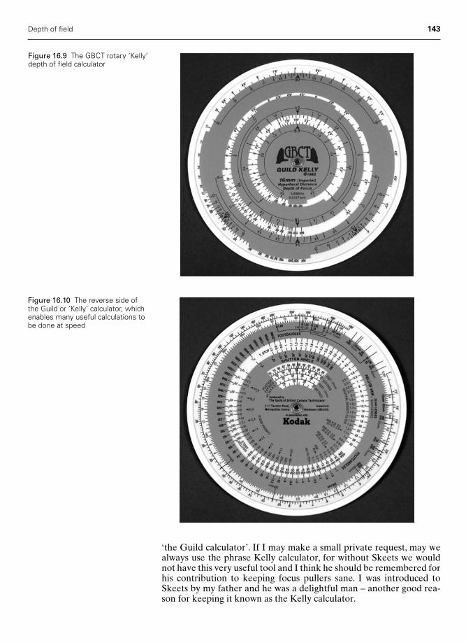
Depth of field 143
Figure 16.9 The GBCT rotary ‘Kelly’depth of field calculator
Figure 16.10 The reverse side ofthe Guild or ‘Kelly’ calculator, whichenables many useful calculations tobe done at speed
‘the Guild calculator’. If I may make a small private request, may wealways use the phrase Kelly calculator, for without Skeets we wouldnot have this very useful tool and I think he should be remembered forhis contribution to keeping focus pullers sane. I was introduced toSkeets by my father and he was a delightful man – another good rea-son for keeping it known as the Kelly calculator.
Chap-16 2/8/05 11:25 AM Page 143

144 Practical Cinematography
Samuelson calculatorsThere have been several generations of the Samuelson calculator, thelatest of which is shown in Figure 16.11. They are more versatile nowin that they will allow calculations using a variety of circles of confu-sion, and the use of both a rotating and a sliding scale are of greatvalue when working with a zoom lens, as an infinite amount of focallengths can be chosen.
Initially, the Samuelson calculator looks complicated,but I know focuspullers who are experienced with it to be very fast and accurate. It is acalculator very much worth considering, as the single unit will work forall lens lengths, all circles of confusion and virtually all image formats.
Digital calculatorsA more recent development is the ability to do your depth of field cal-culations on a palmtop calculator. My favourite is the pCAM depth offield calculator, together with the sophisticated general informationprogram pCINE. Both these programs work on most Palm-based
Figure 16.11 The Samuelson Mk.III depth of field calculator
Chap-16 2/8/05 11:25 AM Page 144

Depth of field 145
hand-held computers, they are incredibly fast and, in my experience,very reliable. Figure 16.12 shows the screen on my Palm m500 calcu-lating the depth of field for a 25 mm lens shooting 35 mm 1:1.85 aspectratio assuming a circle of confusion of one-thousandth of an inch or25.4 microns. It shows all will appear sharp from 7 ft 7 in. to 29 ft 4 in.with the lens focus set at 12 feet. It took this program less than a blinkof an eye to do this calculation.
I have recommended this depth of field calculator to many of mystudents and quite a number of my crews, and almost all of them haveadopted it.
You can download these programs from the Internet. They weredeveloped by an AC1, David Eubank, in association with SuhartoIskandare, and can be found at www.davideubank.com.You can down-load it for free, but as both programs cost only a few dollars I wouldentreat you to pay for them – they are exceptionally good value.
Figure 16.12 A Palm Pilot showinga pCAM screen
Chap-16 2/8/05 11:25 AM Page 145
17
Testing
Why so much checking?
There are two reasons for meticulous preparation of all the equipmentand stores you will need for a shoot.
The first is clearly your own professional pride and the need to packequipment in such a way that the crew can find any piece of equipmentquickly and efficiently, even in the dark of a night shoot. Also, it isessential that all the equipment starts the job in the finest possiblecondition.
The second reason, and indeed the reason for some of the moreobscure test procedures, is that the production company probably raiseda completion bond to insure the picture gets finished and the bond com-pany will require hard evidence that all was well before you started.
A completion bond is a form of insurance taken out by the produc-tion company in order that they, the production company, will be reim-bursed any expenses incurred due to unforeseen circumstances. Forinstance, an artist might become ill during production and delay shoot-ing for several days. The completion bond company will then beresponsible for all additional expenses incurred.
Another example might be several rolls of film being found to bescratched after development. The bond company might have to payfor a reshoot. It is clearly in everyone’s interest to be able to prove thatnone of the camera bodies nor any of the camera magazines werescratched when first loaded onto the camera car at the beginning ofshooting.
For these reasons everything, but everything, must be checked and,where possible, physical proof of a successful check must be available.
Who checks?
The focus puller is normally in charge of the preparation and willalmost always be assisted throughout by the clapper loader. This issensible, for during the shoot the focus puller will be responsible forthe day-to-day running of the camera and the loader will be expected toknow exactly where every single piece of equipment is at any given time.
146
Chap-17 12/16/04 3:18 PM Page 146

If there is more than one camera crew on a shoot, each crew willusually be responsible for, and prepare, their own equipment. Occa-sionally, on very big shoots with multiple cameras, I will nominate ahead focus puller and head loader. This does not denote seniority butis necessary so that any problems with any of the crews’ equipmentcomes through them to me, the DP. This is important as my responsi-bility is to the director and for the photography, and if all the crewscame to me directly it may simply take too much of my time.
Even on a short television shoot a minimum of three days should beallowed for testing.This is a continual bone of contention with the pro-duction office, who frequently profess to see no reason why it can pos-sibly take more than a day and see no reason to find all involved threedays’ pay.The reason for three days is simple.The first day will be verybusy and long, as all the testing requiring film to be run through thecamera must be done on this day. All other matters are put aside.
The following day should, unless the shot tests show major or mul-tiple problems, be easier.The morning of this second day is put aside forthe careful inspection of the test rushes. These may be seen at the hirehouse where testing is normally carried out or you may have to go tothe laboratory to find adequate projection facilities. It is essential thatthe projector and screen used for viewing the tests are of the highestquality. I have known occasions where faults have been seen, a hugeamount of work put into correcting them, and they have eventuallyturned out to be a projector fault. It is also desirable that the projectorused for this viewing has an oversized gate, so that the edges of theframe are visible on the screen; these are rarely found anywhere buthire houses and laboratories.
The third day of testing is required because this world is not perfectand it is very rare for there not to be at least one piece of equipment,and there will often be more than one, that is not up to your standards.This will need maintenance or replacement and will then require a fur-ther film test. This test will be shot on the afternoon of the second dayand viewed on the morning of the third day. If things are still not satis-factory you are in trouble and somebody may then have to havestrong words with the hire house.
Tests that involve shooting film
Tests that involve shooting film include:● Camera steady tests● The frame leader● Scratch tests● Fog tests.
Camera steady testsEvery camera body you are likely to use on the shoot must have a testrun on it to check that the camera mechanism is registering the film inthe camera gate with an accuracy at least as good as the manufacturer’sspecification. This is called the steady test. Many hire houses will settheir own standard a little above the manufacturer’s; if they do, thenwork to this standard.
Testing 147
Chap-17 12/16/04 3:18 PM Page 147
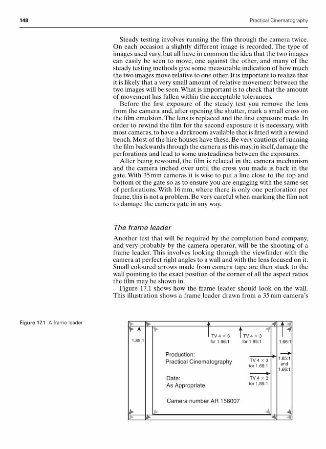
148 Practical Cinematography
Steady testing involves running the film through the camera twice.On each occasion a slightly different image is recorded. The type ofimages used vary, but all have in common the idea that the two imagescan easily be seen to move, one against the other, and many of thesteady testing methods give some measurable indication of how muchthe two images move relative to one other. It is important to realize thatit is likely that a very small amount of relative movement between thetwo images will be seen.What is important is to check that the amountof movement has fallen within the acceptable tolerances.
Before the first exposure of the steady test you remove the lensfrom the camera and, after opening the shutter, mark a small cross onthe film emulsion. The lens is replaced and the first exposure made. Inorder to rewind the film for the second exposure it is necessary, withmost cameras, to have a darkroom available that is fitted with a rewindbench. Most of the hire houses have these. Be very cautious of runningthe film backwards through the camera as this may, in itself, damage theperforations and lead to some unsteadiness between the exposures.
After being rewound, the film is relaced in the camera mechanismand the camera inched over until the cross you made is back in thegate. With 35 mm cameras it is wise to put a line close to the top andbottom of the gate so as to ensure you are engaging with the same setof perforations. With 16 mm, where there is only one perforation perframe, this is not a problem. Be very careful when marking the film notto damage the camera gate in any way.
The frame leaderAnother test that will be required by the completion bond company,and very probably by the camera operator, will be the shooting of aframe leader. This involves looking through the viewfinder with thecamera at perfect right angles to a wall and with the lens focused on it.Small coloured arrows made from camera tape are then stuck to thewall pointing to the exact position of the corner of all the aspect ratiosthe film may be shown in.
Figure 17.1 shows how the frame leader should look on the wall.This illustration shows a frame leader drawn from a 35 mm camera’s
1.85:1 1.66:1 TV 4 � 3for 1.66:1
TV 4 � 3for 1.85:1
TV 4 � 3for 1.66:1
TV 4 � 3for 1.85:1
1.85:1and
1.66:1
Production:Practical Cinematography
Date:As Appropriate
Camera number AR 156007
Figure 17.1 A frame leader
Chap-17 12/16/04 3:18 PM Page 148

viewfinder where the outer frame has an aspect ratio of 1.66:1, whichwill represent the camera gate and, as this can be varied on most35 mm cameras, is known as the ‘hard mask’. The next set of markingsare only different in being slightly shorter in height and represent anaspect ratio of 1.85:1. This is the aspect ratio used in most Europeancinemas. Finally, the much squarer rectangle shows the portion of theframe that will be used for a transfer to tape for television.
The purpose of shooting a frame leader is to reassure both the com-pletion bond company and the camera operator that the aspect ratiomarkings in the viewfinder correspond exactly to the negative aper-ture of the camera gate. This is best done by viewing the negative.Some operators will ask for a length of frame leader to be sent to thelaboratory in order that a short length is printed before each day’srushes or dailies.
The frame leader must be clearly marked with the productionname, the date and the camera identification. This way, there can be no confusion as to which camera and viewfinder markings it refers to.This is not just essential when there are several camera bodies on theshoot, for it is surprising how often one laboratory will have severaltests going through the bath on any given night. This also applies tohire houses who may have several productions testing at once.
This test is not ideally viewed on a projector, but with a low-powered microscope. As I have said, most projectors do not show thefull camera aperture unless they are at the laboratory or hire house,where an oversize gate can often be found; even so, microscopic investi-gation will often be more critical than projection.
There is a further use to which the frame leader can be put. If therushes are being transferred to tape, it is not uncommon for the rushedtelecine to slightly underscan the picture.This produces a tighter com-position than the operator originally framed for. If this is suspected,then a length of frame leader can be sent through with the next batchof rushes and all will be revealed. This needs doing disappointinglyoften. Just as when rushes are to be provided as a film print, someoperators will ask for a length of frame leader to be sent to the trans-fer house making the tape copies in order that a short length is trans-ferred before each day’s rushes. This usually overcomes the problemof the telecine underscanning.
Scratch testsEvery camera magazine must be tested for scratching. This is done byrunning 20 feet or so of film through the camera using each and everymagazine. This simultaneously scratch tests the camera bodies. Thefilm need not be sent to the laboratory – simply unwind the last threeor four feet of film from the take-up side of the magazine and inspectboth sides of the film through a strong magnifying glass.
A trick many loaders use is to ‘catch the light’ on the film whenlooking for scratches. When this is done the surface of the film willshine and any scratches will show up as black lines.
If the film shows short scratches identical on every frame, then aslikely as not either this has occurred in the camera gate or the loop offilm just before or just after the gate has been too big and has rubbedon the camera body at the moment the loop has been at its largest.
Testing 149
Chap-17 12/16/04 3:18 PM Page 149

If a scratch shows as a continuous line, then there is probably some-thing stuck in the light trap of the magazine or possibly one of the lay-on rollers in the magazine is not rotating freely. If the magazineemploys felt rollers as part of the light trap, they may need cleaning.
If you are in any doubt as to where the scratching is occurring, run asecond test and before you remove the film from the camera take the lens out and mark the frame in the gate. Now, when you unload the film you can count the number of frames before or after the gateto the point where the scratch starts. If you now mark this point andreload the camera again with the original marked frame in the gate,your new mark will be exactly where the scratching is occurring.
You will need to check with the completion bond company as towhether they wish to hold a developed copy of your scratch tests. Ifthey do, only shoot them after you are confident your eyeball tests areabsolutely free of scratches and do not run the negative you will besending them through a projector, where further scratching mayoccur. Simply run an eyeball test on the processed negative to reassureyourself all is well.
Fog testsThese are rarely carried out unless you are going to a very hot andsunny country. Point the camera at a wall and write on the wall themagazine number, then underexpose this by at least one stop to give adark grey image on which to look for fogging. Get a strong lamp andrun 20 feet of stock through each magazine while hand-holding thelamp and pointing its beam at all the joins between the magazine doorand its casing, then do the same for the camera door. On project-ing the print you will quickly see whether any light is getting throughthe seals.
With a fog test it is useful to light the room and the magazine num-ber on the wall with a different coloured light than is hand-heldaround the camera and magazine. So if the room and wall are lit bytungsten light, use an HMI daylight lamp for the test. Conversely,if the room and wall are lit with daylight, use a tungsten lamp for thetest. This way even the slightest light leakage can be detected as it willshow up as a different colour to the image on the screen.
Lens testing
All the lenses should have been collimated by the hire house beforedelivery to you for testing. Should your DP be supplying some or all ofthe lenses, then most hire houses will check their collimation free ofcharge. Any faults found should be put right before your testingperiod starts.
The lens tests that must be carried out are:● Infinity test● Resolution test● Focus tests at various distances.
In addition, as many focus pullers do not trust the engraved scale onsome lenses, they insist on marking up critical focus points on plastictape applied around the lens barrel. They will also mark up individual
150 Practical Cinematography
Chap-17 12/16/04 3:18 PM Page 150

focus rings if they are using something like the Arri follow-focusdevice. If this is to be done, then both left-hand and right-hand ringsneed to be prepared.
Infinity testIt is important that all your lenses can focus as far as infinity. To testthis can be taxing as, other than with the iris wide open, there will besufficient depth of field for almost any lens to show infinity as sharp.There is a difference of opinion on this test. Some focus pullers insiston shooting this test, while others feel it is sufficient to eye-test thelenses. My feeling is that an eye test is probably adequate. If youdecide to shoot a test then you have two options. If the camera you areusing has a variable shutter, then you can close this down to obtain thecorrect exposure with the lens wide open. If the camera does not havea variable shutter, then you will have to shoot at dusk or dawn.
You must not, under any circumstances, put neutral density filters infront of the lens for this test. Putting glass filters in front of a lens willalter the point at which the lens focuses on infinity. This is particularlynoticeable with lenses of long focal length. Indeed, it is essential thatall the longer lenses are infinity tested with and without a Wratten 85filter to check they can reach infinity in both conditions. If the DP youare working with tends to use a lot of filters, then test the longer lenseswith several filters on.
You will notice that with most long-focus lenses the focus barrel willgo past infinity. This is to ensure that you can reach infinity with sev-eral filters in front of the lens, as the effect on infinity when addingextra glass to the front of the lens is greater the longer the focal lengthof the lens.
Resolution testThere are a number of wall charts available for lens testing and mostof them employ a series of parallel white lines on a black surface. Thelines are so arranged in blocks of finer and finer lines in order to dis-cover how fine the line must be before the lines cannot be seen apart.This is the limit of the lens’s resolution. These measurements onlywork if the chart exactly fills the frame.A good example of such a lenstest chart, designed and produced by KJM Consultants for Panavision,can be seen in Figure 17.2. Do not copy and use this illustration fromthe book – if reproduced in this way it will not have sufficiently finedefinition to give any meaningful results.
These days it is more common to test the finite resolution of a lenson the bench either by measuring its MTF (modular transfer function)or by projecting a very accurate chart, similar in appearance to thatdescribed above, through the lens onto a wall where, due to the largesize of the projected image, the judgement of which are the finest linesresolved can more easily be made.
The testing of the ultimate resolving power of a lens is best done inconjunction with the specialist at your hire house. If you have workedwith the hire house before and trust them, then you can, quite reason-ably, ask them to have checked all the lenses before you start yourtesting.
Testing 151
Chap-17 12/16/04 3:18 PM Page 151
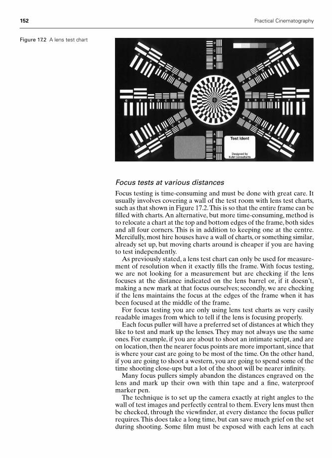
152 Practical Cinematography
Focus tests at various distancesFocus testing is time-consuming and must be done with great care. Itusually involves covering a wall of the test room with lens test charts,such as that shown in Figure 17.2.This is so that the entire frame can befilled with charts. An alternative, but more time-consuming, method isto relocate a chart at the top and bottom edges of the frame, both sidesand all four corners. This is in addition to keeping one at the centre.Mercifully, most hire houses have a wall of charts, or something similar,already set up, but moving charts around is cheaper if you are havingto test independently.
As previously stated, a lens test chart can only be used for measure-ment of resolution when it exactly fills the frame. With focus testing,we are not looking for a measurement but are checking if the lensfocuses at the distance indicated on the lens barrel or, if it doesn’t,making a new mark at that focus ourselves; secondly, we are checkingif the lens maintains the focus at the edges of the frame when it hasbeen focused at the middle of the frame.
For focus testing you are only using lens test charts as very easilyreadable images from which to tell if the lens is focusing properly.
Each focus puller will have a preferred set of distances at which theylike to test and mark up the lenses. They may not always use the sameones. For example, if you are about to shoot an intimate script, and areon location, then the nearer focus points are more important, since thatis where your cast are going to be most of the time. On the other hand,if you are going to shoot a western, you are going to spend some of thetime shooting close-ups but a lot of the shoot will be nearer infinity.
Many focus pullers simply abandon the distances engraved on thelens and mark up their own with thin tape and a fine, waterproofmarker pen.
The technique is to set up the camera exactly at right angles to thewall of test images and perfectly central to them. Every lens must thenbe checked, through the viewfinder, at every distance the focus pullerrequires.This does take a long time, but can save much grief on the setduring shooting. Some film must be exposed with each lens at each
Figure 17.2 A lens test chart
Chap-17 12/16/04 3:18 PM Page 152
position. Ideally, two exposures should be made, one at the maximumaperture of the individual lens and another at a stop the DP nominatesas one they will be using a lot.
Do make sure that the lens flange to film plane depth and the lensflange to viewing screen distance have been checked to the highestpossible standards available by the camera supplier before you carryout the focus tests, otherwise you are wasting your time.
Gamma testing
The last test that requires film to be sent to the laboratory is thegamma test. This requires you to remove 30–50 feet of film from a rollof every type and batch of film you will be using during production.When asked to carry out a gamma test the laboratory will make anexposure on each sample using a sensitometer: they will process thefilm and, using a densitometer, will read off the sensitometric curve forall three colour layers of the negative.They will send back the test nega-tives together with graphs of the sensitometric curves.
As reading these graphs takes experience and specialist knowledge,it is quite reasonable to phone the laboratory and ask them if the testswere satisfactory. If you wish to be doubly safe, ask them to fax theproduction office with their opinion.
What to do with the film tests
Having successfully completed all the film tests described above, theyshould all be gathered together and carefully labelled. Most usuallythey will then be lodged with the cutting room, assuming the editorhas started at the beginning of shooting. Occasionally, they may besent to the production office or the completion bond company. Askthe production office which they prefer.
Non-film testing
There are a number of non-film tests that it is prudent to carry out:
● Batteries● Tripods● Heads.
BatteriesIt is sensible to fully charge all your batteries as soon as possible andleave them untouched during your testing days. Check them at the endof your testing period – they should all have held a full charge overseveral days; any that have not should be changed.
TripodsThis may be done by the dolly grip, but all the tripod legs should betested to make sure they are in good condition and that they lock
Testing 153
Chap-17 12/16/04 3:18 PM Page 153

properly. This may seem obvious, but on a recent shoot a tripod leggave way and deposited a quarter of a million pounds worth of cameraand lens assembly rather dramatically on the studio floor – an embar-rassment one would wish to prevent at all cost.
HeadsEvery tripod head should be checked. Geared heads need skilledadjustment and many operators will want to check them themselves.Some operators provide their own heads. If this is the case, then it can safely be assumed that they will bring them to the set in perfectcondition.
Fluid heads should be checked for smooth movement over thewhole of their range and on every friction setting. It is also wise to setthem up on the first day of testing and just leave them standing tocheck for any fluid leaks.
Remote heads can be a problem as they often arrive with a crane onthe day they are going to be used and therefore you have no chance totest them. Fortunately, the crane and head should come with a skilled,specialist operator and all will be well. If you are having a remote headfrom the start of production, make sure whoever is going to operate itis happy with its performance.
Stores, supplies and expendables
Ordering expendable stores before starting production can be atouchy business – great care should be exercised. Some productionoffices are unaware of the quantity of consumables that will be usedon a large production. Some have, sadly, been persuaded to purchasefar more than could possibly have been needed and know full wellthat the over-ordering was used to stock personal supplies. As you aregoing to be working with the production office for the duration of theshoot, it is as well to get off to a good working relationship. Therefore,order your stores, supplies and expendables with care.
On a long production it is wise to order only the amount of storesetc. you will need to get halfway through the schedule. You can makethis clear to the production office, thus making them aware that youwill only reorder as needs be. My crews have, in the past, found this agood and reliable strategy.
Many hire houses have in-house shops or store rooms and are onlytoo happy to supply most of your needs on site. They are often goodvalue but do check, as overcharging annoys the office as much as over-ordering.
Your report sheet books and can labels should be obtained from thelaboratory you intend to use. As the layout will be familiar to them,this reduces the possibility of any misunderstanding. The laboratorycan, as often as not, supply you with spare film tins. Extra film bagsshould be purchased new – only the bag the film came in from themanufacturer should ever have a roll of rushes put back into it. Neveruse a bag that has previously been used by someone else – you have noidea what dirt and dust it may contain. Film cores can also usually beobtained from the laboratory; if not, then try the stock supplier oryour hire house.
154 Practical Cinematography
Chap-17 12/16/04 3:18 PM Page 154

Testing 155
I know a loader who has designed a report sheet blank on his laptopcomputer. During the day he fills in the sheet as he goes along andprints it out at the end of the day.This is very impressive, but does lackthe familiarity aspect of the laboratory’s own report sheet. Perhaps ifthis appeals to you a good idea may be to send a blank copy to the labora-tory contact for approval. They will probably be quite happy with thisand it will overcome the familiarity problem, as well as starting a goodworking relationship with the laboratory.
If you use computers for any purpose when filming, always backyour work up regularly and keep the backup in a separate place fromthe computer. Computers are replaceable and should be insured, butthe greatest value is often the information they contain and this can beirreplaceable. If you are going to have your computer with you on aregular basis, it might be a good idea to ask the production office toadd it to the company’s insurance list.
The all-important 18 per cent grey cards can be obtained from thelaboratory, Kodak or several independent suppliers. I get mine directlyfrom Kodak, put my message on them as I have described and bring myown to the set. My regular loaders now order them for me and presentthem to me on the first day of shooting already labelled. Whatevercards you order, check with the DP first to find out their preference.
The current trend for clapperboards is to use what have becomeknown as ‘backlight boards’; the layout of a typical backlight board isshown in Figure 17.3.These have the clap sticks still made out of wood,but the board is made from white, translucent Perspex or Plexiglas.The idea is that they should be just as effective when lit from the frontas from the back, which indeed they are. Temporary marks on theboard, such as slate numbers, are made with a dry marker pen and cantherefore be easily rubbed off. I very much favour them, as anythingthat makes the board easier for the cutting room to read must be agood thing.
Production:
Director:
Roll No. Slate
DoP:
Take
Date
Int.Ext
MuteSync
DayNight
Figure 17.3 The backlightclapperboard
Chap-17 12/16/04 3:18 PM Page 155
156 Practical Cinematography
If the production is sufficiently well funded and is to shoot for a rea-sonable time, then it is worth having the backlight board engravedwith all the permanent information. If not, put waterproof adhesivetape on the board first, mark the information with a waterproofmarker and then cover with a further layer of waterproof tape. Thismakes for an easily readable board, the backlight idea still works andthe whole lot can be peeled off at the end of the production.
One thing I do not approve of, and most of the backlight boards suf-fer from it, is the marking of the lines on the clap sticks with the upperand lower lines going in the same direction. They should go in theopposite directions, as in a chevron, as this makes it much easier forwhoever is synching up the rushes to see the exact moment the twosticks come together.
The camera car
Calling it a camera car is a hangover from the past as nowadays it is, asoften as not, a three-ton truck! Ideally, the sides of the truck shouldhave shelving with a large lip or bar at the front so that cases of equip-ment can travel in complete safety.A bench is essential for assemblingthe camera.
Some trucks come with a small darkroom in one corner. This looksto be a good idea but it is essential that the loader checks that thedarkroom is totally lightproof. This can be a time-consuming andunpleasant exercise, as one only acquires full night vision after 20 min-utes, and 20 minutes in a small, dark and airless room can be a taxingaffair even if you have taken your MP3 player with you.
Distrust of camera car darkrooms has led several loaders I know toprefer a second bench on which they can leave their Harrison chan-ging tent permanently set up. If a darkroom is still fitted it usuallybecomes a store for consumables so as not to waste space.
If you are filming in the height of summer or in hot climates, a smallfridge for the day’s film stock is a good idea. Clearly, it will need plug-ging in to a power supply, but a friendly word with the gaffer will usu-ally ensure one awaits you on arrival at every location. It is surprisinghow long a fridge will stay adequately cool when switched off provid-ing the door is never opened. See Chapter 6 for guidance as to storingfilm stock at different temperatures.
Once the habit of supplying power to the camera car has beenestablished, a kettle and a coffee machine are a good idea, especiallyon cold night shoots. Make sure the fridge has sufficient space for allthe film stock – in hot countries it is not uncommon for cans of cokeand beer to mysteriously find their way into the fridge. Before lettingany drinks into the fridge, do check if you are on an alcohol-free pro-duction; if you are, then be rigorous about not letting your fridge getso contaminated, as I can envisage a situation where the loader incharge of the fridge could get fired when, unknown to them, somefriendly person has stocked up.
Offering refreshment to the lighting and grip crew usually ensuresadequate power supplies, though I must admit to being lucky in thisrespect, as my regular lighting crew insist on taking over the coffeeand tea duties and have even presented me with a thermally insulatedmug with their nickname for me engraved on it – that’s service!
Chap-17 12/16/04 3:18 PM Page 156

Part Four
Operating
Chap-18 12/16/04 3:18 PM Page 157

This page intentionally left blank
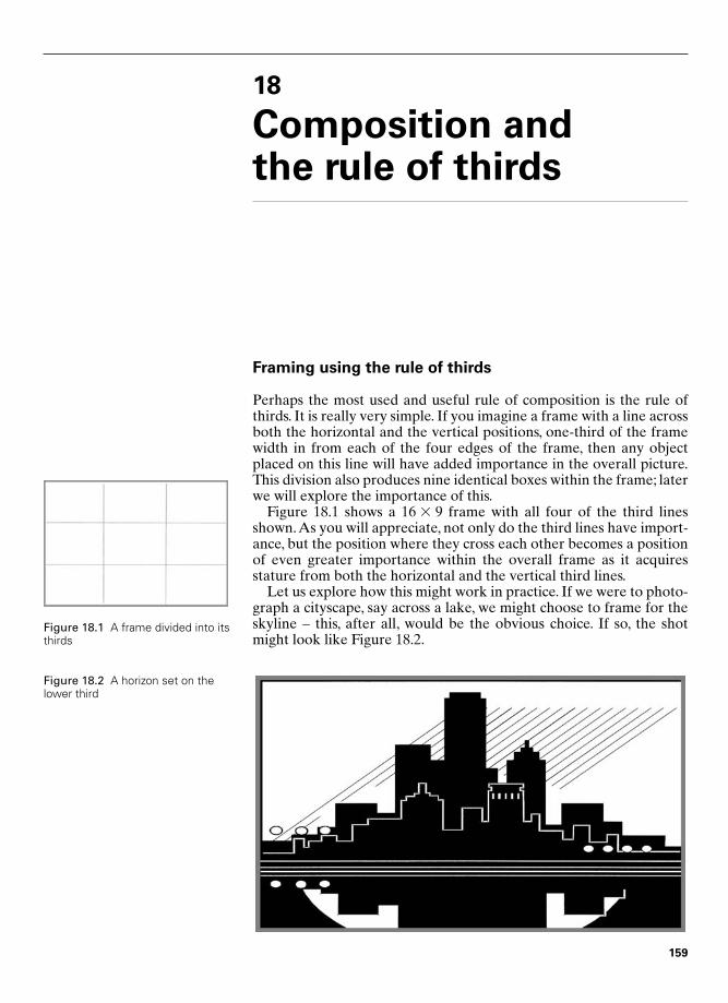
18
Composition and the rule of thirds
Framing using the rule of thirds
Perhaps the most used and useful rule of composition is the rule ofthirds. It is really very simple. If you imagine a frame with a line acrossboth the horizontal and the vertical positions, one-third of the framewidth in from each of the four edges of the frame, then any objectplaced on this line will have added importance in the overall picture.This division also produces nine identical boxes within the frame; laterwe will explore the importance of this.
Figure 18.1 shows a 16 � 9 frame with all four of the third linesshown.As you will appreciate, not only do the third lines have import-ance, but the position where they cross each other becomes a positionof even greater importance within the overall frame as it acquiresstature from both the horizontal and the vertical third lines.
Let us explore how this might work in practice. If we were to photo-graph a cityscape, say across a lake, we might choose to frame for theskyline – this, after all, would be the obvious choice. If so, the shotmight look like Figure 18.2.
Figure 18.1 A frame divided into itsthirds
159
Figure 18.2 A horizon set on thelower third
Chap-18 12/16/04 3:18 PM Page 159
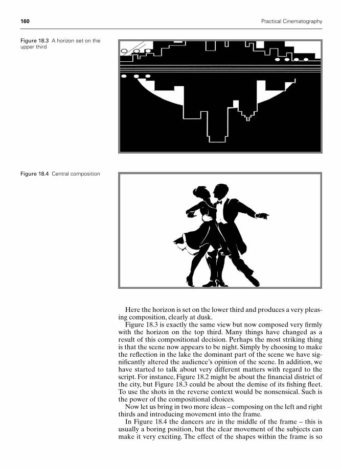
Here the horizon is set on the lower third and produces a very pleas-ing composition, clearly at dusk.
Figure 18.3 is exactly the same view but now composed very firmlywith the horizon on the top third. Many things have changed as aresult of this compositional decision. Perhaps the most striking thing is that the scene now appears to be night. Simply by choosing to makethe reflection in the lake the dominant part of the scene we have sig-nificantly altered the audience’s opinion of the scene. In addition, wehave started to talk about very different matters with regard to thescript. For instance, Figure 18.2 might be about the financial district ofthe city, but Figure 18.3 could be about the demise of its fishing fleet.To use the shots in the reverse context would be nonsensical. Such isthe power of the compositional choices.
Now let us bring in two more ideas – composing on the left and rightthirds and introducing movement into the frame.
In Figure 18.4 the dancers are in the middle of the frame – this isusually a boring position, but the clear movement of the subjects canmake it very exciting. The effect of the shapes within the frame is so
160 Practical Cinematography
Figure 18.3 A horizon set on theupper third
Figure 18.4 Central composition
Chap-18 12/16/04 3:18 PM Page 160
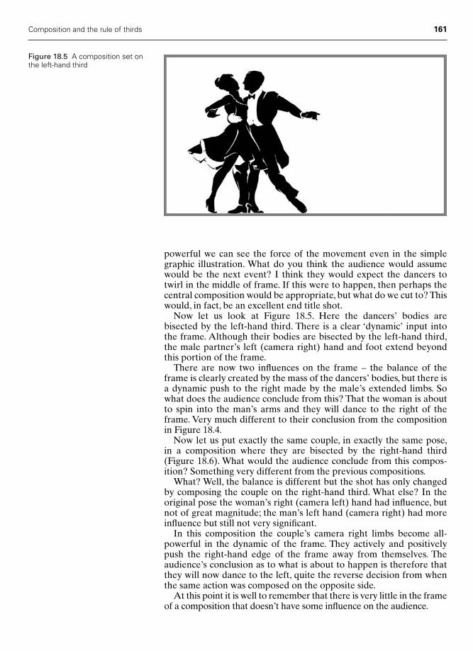
powerful we can see the force of the movement even in the simplegraphic illustration. What do you think the audience would assumewould be the next event? I think they would expect the dancers totwirl in the middle of frame. If this were to happen, then perhaps thecentral composition would be appropriate, but what do we cut to? Thiswould, in fact, be an excellent end title shot.
Now let us look at Figure 18.5. Here the dancers’ bodies arebisected by the left-hand third. There is a clear ‘dynamic’ input intothe frame. Although their bodies are bisected by the left-hand third,the male partner’s left (camera right) hand and foot extend beyondthis portion of the frame.
There are now two influences on the frame – the balance of theframe is clearly created by the mass of the dancers’ bodies, but there isa dynamic push to the right made by the male’s extended limbs. Sowhat does the audience conclude from this? That the woman is aboutto spin into the man’s arms and they will dance to the right of theframe. Very much different to their conclusion from the compositionin Figure 18.4.
Now let us put exactly the same couple, in exactly the same pose,in a composition where they are bisected by the right-hand third(Figure 18.6). What would the audience conclude from this compos-ition? Something very different from the previous compositions.
What? Well, the balance is different but the shot has only changedby composing the couple on the right-hand third. What else? In theoriginal pose the woman’s right (camera left) hand had influence, butnot of great magnitude; the man’s left hand (camera right) had moreinfluence but still not very significant.
In this composition the couple’s camera right limbs become all-powerful in the dynamic of the frame. They actively and positivelypush the right-hand edge of the frame away from themselves. Theaudience’s conclusion as to what is about to happen is therefore thatthey will now dance to the left, quite the reverse decision from whenthe same action was composed on the opposite side.
At this point it is well to remember that there is very little in the frameof a composition that doesn’t have some influence on the audience.
Composition and the rule of thirds 161
Figure 18.5 A composition set onthe left-hand third
Chap-18 12/16/04 3:18 PM Page 161

Framing using the sixths
Just as in music, in composition we too have the equivalent of theminor chords. In the world of cinematography these are the lines ofthe sixths – that is, any line one-sixth of the way in from any edge ofthe frame or one-sixth of the frame width out from the centre of theframe. The sixths coming out from the centre of the frame are veryweak in terms of compositional power, but those coming in from theoutside edge do have an appreciable power. Their power is far lessthan the power of the thirds, but nevertheless it is a very useful com-positional tool.
In Figure 18.7 the skyline is contained within the bottom sixth of the frame. It makes a very pleasing composition, especially if in thebackground there was, say, an attractive sunset. In fact, almost anyinteresting object, on an important third or sixth, would, of course,heighten the dramatic power of the composition. Leaving five-sixths of the frame free causes this space to be very vulnerable in as
162 Practical Cinematography
Figure 18.6 A composition set onthe right-hand third
Figure 18.7 A composition set onthe lower sixth
Chap-18 12/16/04 3:18 PM Page 162
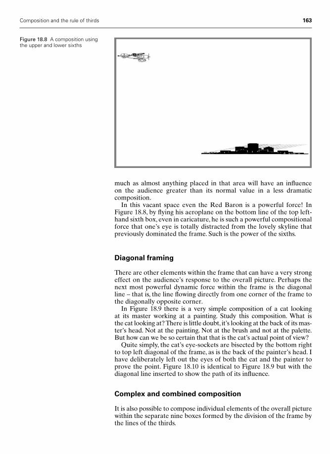
much as almost anything placed in that area will have an influence on the audience greater than its normal value in a less dramatic composition.
In this vacant space even the Red Baron is a powerful force! InFigure 18.8, by flying his aeroplane on the bottom line of the top left-hand sixth box, even in caricature, he is such a powerful compositionalforce that one’s eye is totally distracted from the lovely skyline thatpreviously dominated the frame. Such is the power of the sixths.
Diagonal framing
There are other elements within the frame that can have a very strongeffect on the audience’s response to the overall picture. Perhaps thenext most powerful dynamic force within the frame is the diagonalline – that is, the line flowing directly from one corner of the frame tothe diagonally opposite corner.
In Figure 18.9 there is a very simple composition of a cat looking at its master working at a painting. Study this composition. What is the cat looking at? There is little doubt, it’s looking at the back of its mas-ter’s head. Not at the painting. Not at the brush and not at the palette.But how can we be so certain that that is the cat’s actual point of view?
Quite simply, the cat’s eye-sockets are bisected by the bottom rightto top left diagonal of the frame, as is the back of the painter’s head. Ihave deliberately left out the eyes of both the cat and the painter toprove the point. Figure 18.10 is identical to Figure 18.9 but with thediagonal line inserted to show the path of its influence.
Complex and combined composition
It is also possible to compose individual elements of the overall picturewithin the separate nine boxes formed by the division of the frame bythe lines of the thirds.
Composition and the rule of thirds 163
Figure 18.8 A composition usingthe upper and lower sixths
Chap-18 12/16/04 3:18 PM Page 163
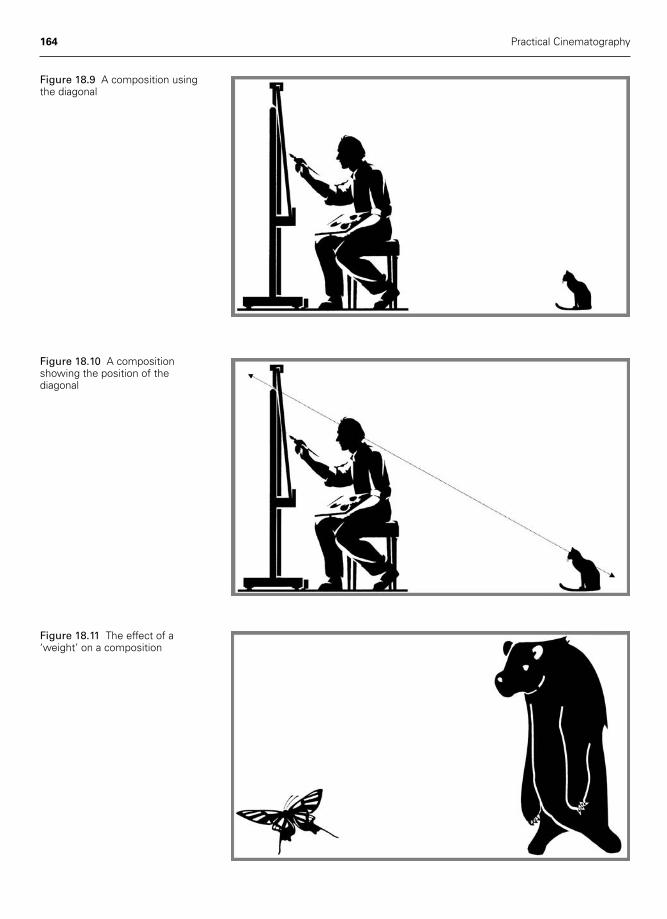
164 Practical Cinematography
Figure 18.9 A composition usingthe diagonal
Figure 18.10 A compositionshowing the position of thediagonal
Figure 18.11 The effect of a‘weight’ on a composition
Chap-18 12/16/04 3:18 PM Page 164

Composition and the rule of thirds 165
Another variation is to combine different compositions within dif-ferent elements of a single frame. Let us say that we are going to put a‘heavy’ object within the right-hand vertical three boxes and a small,perhaps fragile, object in the bottom left-hand third box. If the subjectlooming in the right-hand third could be made to have an eyeline tothe subject in the lower left-hand box, we would have a very effectivecomposition.
Figure 18.11 is such a composition. The bear on the right is wholly composed within the right-hand third, while the butterfly isbeautifully contained and composed within the lower left-hand thirdbox. Here, combining at least two rules has given us an unusual andvery effective composition. There are many, many variations on this,and other, themes.
Chap-18 12/16/04 3:18 PM Page 165

19
Lenses and perspective
Frame size and focal length
Figure 19.1 represents a general view of a city scene. Marked on it arethe framings for a wide-angle lens, a medium-angle lens and a mediumclose lens. As you can see, the different lenses only select differentamounts of the scene. There is no change in perspective – none of thefigures or items in the shot change their relationship to each other.
In Figure 19.2 you can see four more lens sizes – again there is norelational change between the elements of the scene in the differentframings, even though the frame size has now changed radically.
In Figure 19.3 the framings for even more extreme long focallengths are illustrated and again the relationships haven’t changed.
Figure 19.1 A wide-angle,medium-angle and mediumclose view
166
Chap-19 2/8/05 11:27 AM Page 166

Lenses and perspective 167
If you were filming in Super 16, the widest framing in Figure 19.1would perhaps be taken on a 9.5 mm lens and the tightest framing inFigure 19.3 would be at least a 500 mm lens.
What has happened is we have simply selected smaller and smallersegments of the original scene. Now, for the storytelling purposes ofthe film this might be just what we want, going closer and closer untilwe isolate the girl either within the middle of the scene, or even fromthe scene, thus concentrating the audience on that one person.
Perspective
Whereas in Figures 19.1–19.3 the camera was a very long way awayfrom the subject and all the elements of the scene were relatively close
Figure 19.2 Close shots
Figure 19.3 Long focal lensshots
Chap-19 2/8/05 11:27 AM Page 167

168 Practical Cinematography
Figure 19.6 Close shot onSuper 16 mm
Figure 19.4 A wide shot onSuper 16 mm
Figure 19.5 Medium shoton Super 16 mm
Chap-19 2/8/05 11:27 AM Page 168
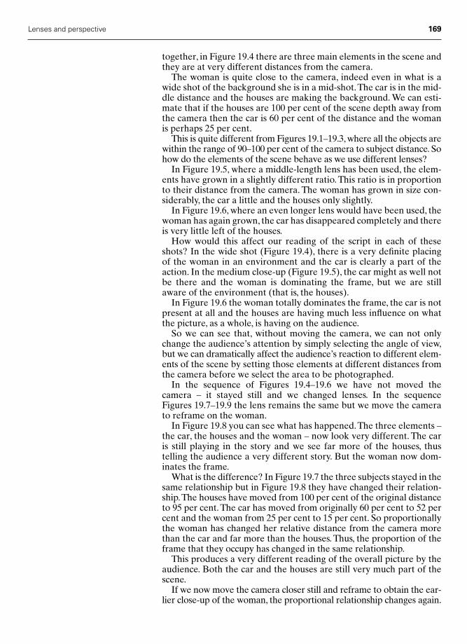
Lenses and perspective 169
together, in Figure 19.4 there are three main elements in the scene andthey are at very different distances from the camera.
The woman is quite close to the camera, indeed even in what is awide shot of the background she is in a mid-shot.The car is in the mid-dle distance and the houses are making the background. We can esti-mate that if the houses are 100 per cent of the scene depth away fromthe camera then the car is 60 per cent of the distance and the womanis perhaps 25 per cent.
This is quite different from Figures 19.1–19.3, where all the objects arewithin the range of 90–100 per cent of the camera to subject distance. Sohow do the elements of the scene behave as we use different lenses?
In Figure 19.5, where a middle-length lens has been used, the elem-ents have grown in a slightly different ratio. This ratio is in proportionto their distance from the camera. The woman has grown in size con-siderably, the car a little and the houses only slightly.
In Figure 19.6, where an even longer lens would have been used, thewoman has again grown, the car has disappeared completely and thereis very little left of the houses.
How would this affect our reading of the script in each of theseshots? In the wide shot (Figure 19.4), there is a very definite placing of the woman in an environment and the car is clearly a part of theaction. In the medium close-up (Figure 19.5), the car might as well notbe there and the woman is dominating the frame, but we are stillaware of the environment (that is, the houses).
In Figure 19.6 the woman totally dominates the frame, the car is notpresent at all and the houses are having much less influence on whatthe picture, as a whole, is having on the audience.
So we can see that, without moving the camera, we can not onlychange the audience’s attention by simply selecting the angle of view,but we can dramatically affect the audience’s reaction to different elem-ents of the scene by setting those elements at different distances fromthe camera before we select the area to be photographed.
In the sequence of Figures 19.4–19.6 we have not moved the camera – it stayed still and we changed lenses. In the sequence Figures 19.7–19.9 the lens remains the same but we move the camerato reframe on the woman.
In Figure 19.8 you can see what has happened.The three elements –the car, the houses and the woman – now look very different. The caris still playing in the story and we see far more of the houses, thustelling the audience a very different story. But the woman now dom-inates the frame.
What is the difference? In Figure 19.7 the three subjects stayed in thesame relationship but in Figure 19.8 they have changed their relation-ship.The houses have moved from 100 per cent of the original distanceto 95 per cent. The car has moved from originally 60 per cent to 52 percent and the woman from 25 per cent to 15 per cent. So proportionallythe woman has changed her relative distance from the camera morethan the car and far more than the houses. Thus, the proportion of theframe that they occupy has changed in the same relationship.
This produces a very different reading of the overall picture by theaudience. Both the car and the houses are still very much part of thescene.
If we now move the camera closer still and reframe to obtain the ear-lier close-up of the woman, the proportional relationship changes again.
Chap-19 2/8/05 11:27 AM Page 169

170 Practical Cinematography
Figure 19.7 Medium shot fromsame camera position
Figure 19.8 Medium shot usingwider lens
Figure 19.9 Close-up usingwide-angle lens
Chap-19 2/8/05 11:27 AM Page 170

Lenses and perspective 171
The houses are 90 per cent of the original distance, the car, say, 40 percent and the woman now,say,5 per cent of the scene depth in Figure 19.7.
What has happened? By comparison with the earlier close-up,things are very different. Again, we have a proportional change andagain both the car and the houses are still in the story, so we are stilldiscussing these elements of the scene with the audience.
One unfortunate thing has occurred, though. Carefully compare theclose-ups in Figures 19.6 and 19.9. You will notice that the woman’sface has become wider and a little distorted. This is a very commoneffect when taking a close-up on a wide-angle lens and should beguarded against. It must be handled very carefully and, if possible, shouldnot be allowed to happen to the extent that a lay audience will evernotice it. Your actors and your producer, who has in all probability paidthem large sums, will not thank you if you photograph them in this way.
But how has this distortion come about? It is simple – we havebrought the camera so near that the proportional differences we dis-cussed earlier now affect the contours of the face. At this distance, thecamera is so close that the tip of the woman’s nose is probably some70 per cent of the distance to her ear lobes, so the proportional differ-ence in size that affected the car and the houses is now sufficientlygreat as to affect the shape of her face.
Any lens wider than that considered normal for the format you areusing should be avoided for a close-up. In fact, if at all possible, noclose-up should ever be made on a lens less than twice the focal lengthof a normal lens.
So we see that we can never choose a lens for just its angle of view –the perspective that goes with that choice must always be considered.
Focal length and emotional involvement
Camera placementIt is important to remember that where you place your camera or,more exactly, where you place the nodal point of your taking lens iswhere you place your audience.
Think of it this way: the human eye is roughly spherical and whenlooking left or right, up or down, is rotating about the centre of thatsphere as the eyeball swivels in the eye socket.With a camera lens, theoptical centre of the lens, its nodal point, is the point where if youswivel the lens and camera about this point the image will appear toneither track left or right nor move up or down. Gears, and a few fluidheads, are constructed so that the pan and tilt movements can bothrotate about the nodal point of the lens. When this is done the cameramovements will be as close to the way a human eye rotates in itssocket and therefore feel the most natural.
Extending this argument, it becomes clear that if we wish to eitherinvolve the audience in the action, or make it feel they are at a dis-tance, where we figuratively place the centre of their eye will makethem feel they are at that distance from the subject.
So choosing the camera position is very important, for it is alsochoosing the emotional position of the audience; this position willbecome the place they would physically expect to be observing fromwere they present, in real life, at the action to be photographed.
Chap-19 2/8/05 11:27 AM Page 171
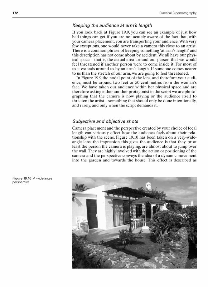
Keeping the audience at arm’s lengthIf you look back at Figure 19.9, you can see an example of just howbad things can get if you are not acutely aware of the fact that, withyour camera placement, you are transporting your audience.With veryfew exceptions, one would never take a camera this close to an artist.There is a common phrase of keeping something ‘at arm’s length’ andthis description has not come about by accident.We all have our phys-ical space – that is, the actual area around our person that we wouldfeel threatened if another person were to come inside it. For most ofus it extends around us by an arm’s length. If someone comes nearerto us than the stretch of our arm, we are going to feel threatened.
In Figure 19.9 the nodal point of the lens, and therefore your audi-ence, must be around two feet or 50 centimetres from the woman’sface. We have taken our audience within her physical space and aretherefore asking either another protagonist in the script we are photo-graphing that the camera is now playing or the audience itself tothreaten the artist – something that should only be done intentionally,and rarely, and only when the script demands it.
Subjective and objective shotsCamera placement and the perspective created by your choice of focallength can seriously affect how the audience feels about their rela-tionship with the scene. Figure 19.10 has been taken on a very-wide-angle lens; the impression this gives the audience is that they, or atleast the person the camera is playing, are almost about to jump overthe wall.They are highly involved with the action or positioning of thecamera and the perspective conveys the idea of a dynamic movementinto the garden and towards the house. This effect is described as
172 Practical Cinematography
Figure 19.10 A wide-angleperspective
Chap-19 2/8/05 11:27 AM Page 172
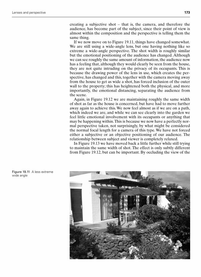
Lenses and perspective 173
Figure 19.11 A less extremewide angle
creating a subjective shot – that is, the camera, and therefore the audience, has become part of the subject, since their point of view isalmost within the composition and the perspective is telling them thesame thing.
If we now move on to Figure 19.11, things have changed somewhat.We are still using a wide-angle lens, but one having nothing like soextreme a wide-angle perspective. The shot width is roughly similarbut the emotional positioning of the audience has changed. Althoughwe can see roughly the same amount of information, the audience nowhas a feeling that, although they would clearly be seen from the house,they are not quite intruding on the privacy of its occupants. This isbecause the drawing power of the lens in use, which creates the per-spective, has changed and this, together with the camera moving awayfrom the house to get as wide a shot, has forced inclusion of the outerwall to the property; this has heightened both the physical, and moreimportantly, the emotional distancing, separating the audience fromthe scene.
Again, in Figure 19.12 we are maintaining roughly the same widthof shot as far as the house is concerned, but have had to move furtheraway again to achieve this. We now feel almost as if we are on a path,which indeed we are, and while we can see clearly into the garden wefeel little emotional involvement with its occupants or anything thatmay be happening within.This is because we now have a perfectly nor-mal perspective taken, not surprisingly, by what might be consideredthe normal focal length for a camera of this type. We have not forcedeither a subjective or an objective positioning of our audience. Therelationship between subject and viewer is completely relaxed.
In Figure 19.13 we have moved back a little further while still tryingto maintain the same width of shot. The effect is only subtly differentfrom Figure 19.12, but can be important. By occluding the view of the
Chap-19 2/8/05 11:27 AM Page 173

174 Practical Cinematography
terrace we have, in a certain way, made it more interesting, a littlemore mysterious.
If we go back further still, and attempt to maintain the size of thehouse in the frame, on this location we are forced to include somebranches in the foreground, thus giving the impression that the camerais almost a ‘peeping Tom’ and is observing the house very much withoutthe occupant’s permission, as in Figure 19.14. We have now reachedthe focal length and therefore the perspective that makes this very
Figure 19.12 Shot with amore ‘normal’ lens
Figure 19.13 A longer lens
Chap-19 2/8/05 11:27 AM Page 174

Lenses and perspective 175
much an objective or observational shot, very definitely not a subjec-tive one.
Now let us consider what might happen if we take the camera stillfurther away and put on a still longer focal length lens. Figure 19.15 isjust this and now, simply by changing camera position and focal lengthof the lens, we are truly emotionally observational in our relationshipwith the house and its occupants. This is observational in the extreme,almost a surveillance shot.
Figure 19.14 A mediumtelephoto lens
Figure 19.15 A longtelephoto lens
Chap-19 2/8/05 11:27 AM Page 175

What is a ‘normal’ focal length lens?
In all that has gone before in this chapter, we have been discussing themany and different effects on the image, perspective and emotions ofour audience of our decision to choose a lens of one focal length oranother. But is it possible to decide what is a ‘normal’ lens for anygiven format? It is very simple – the focal length of a ‘normal’ lens willbe the same as the dimension on the diagonal of the frame formatbeing used.
Therefore, for a standard Academy 35 mm frame the dimensionsare as shown in Figure 19.16, though in this instance all the dimensionsare specified in imperial measurements, i.e. inches.The diagonal comesout at 1.073 in. or as near as makes no difference a 25 mm lens.
176 Practical Cinematography
0.868��
0.63
1��
1.073��
Figure 19.16 Calculating a ‘normal’focal length lens for a given format size
Chap-19 2/8/05 11:27 AM Page 176
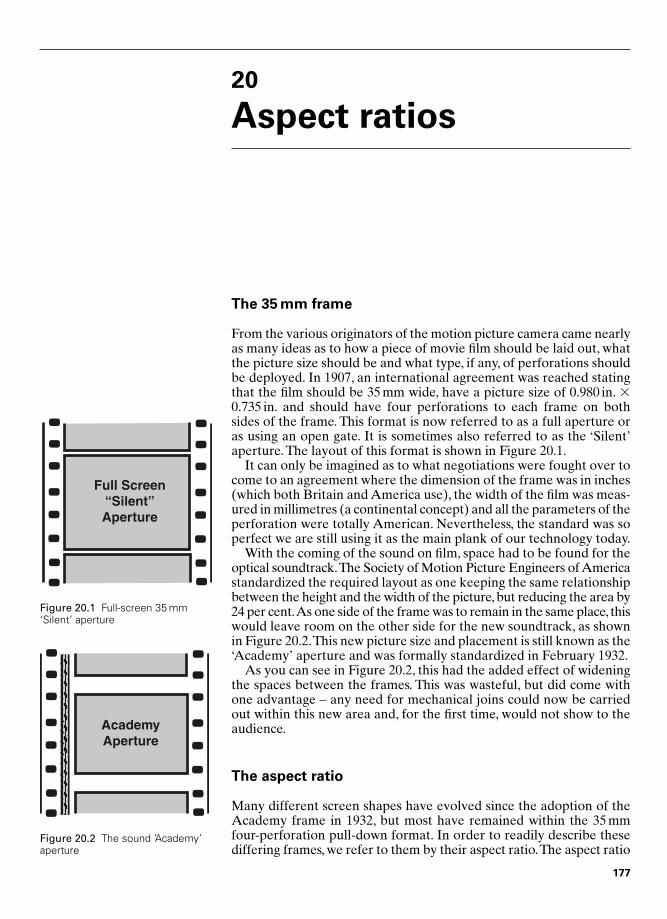
20
Aspect ratios
The 35 mm frame
From the various originators of the motion picture camera came nearlyas many ideas as to how a piece of movie film should be laid out, whatthe picture size should be and what type, if any, of perforations shouldbe deployed. In 1907, an international agreement was reached statingthat the film should be 35 mm wide, have a picture size of 0.980 in. �0.735 in. and should have four perforations to each frame on bothsides of the frame. This format is now referred to as a full aperture oras using an open gate. It is sometimes also referred to as the ‘Silent’aperture. The layout of this format is shown in Figure 20.1.
It can only be imagined as to what negotiations were fought over tocome to an agreement where the dimension of the frame was in inches(which both Britain and America use), the width of the film was meas-ured in millimetres (a continental concept) and all the parameters of theperforation were totally American. Nevertheless, the standard was soperfect we are still using it as the main plank of our technology today.
With the coming of the sound on film, space had to be found for theoptical soundtrack.The Society of Motion Picture Engineers of Americastandardized the required layout as one keeping the same relationshipbetween the height and the width of the picture, but reducing the area by24 per cent.As one side of the frame was to remain in the same place, thiswould leave room on the other side for the new soundtrack, as shownin Figure 20.2.This new picture size and placement is still known as the‘Academy’ aperture and was formally standardized in February 1932.
As you can see in Figure 20.2, this had the added effect of wideningthe spaces between the frames. This was wasteful, but did come withone advantage – any need for mechanical joins could now be carriedout within this new area and, for the first time, would not show to theaudience.
The aspect ratio
Many different screen shapes have evolved since the adoption of theAcademy frame in 1932, but most have remained within the 35 mmfour-perforation pull-down format. In order to readily describe thesediffering frames, we refer to them by their aspect ratio.The aspect ratio
Full Screen“Silent”Aperture
Figure 20.1 Full-screen 35 mm‘Silent’ aperture
AcademyAperture
Figure 20.2 The sound ‘Academy’aperture
177
Chap-20 2/8/05 11:28 AM Page 177
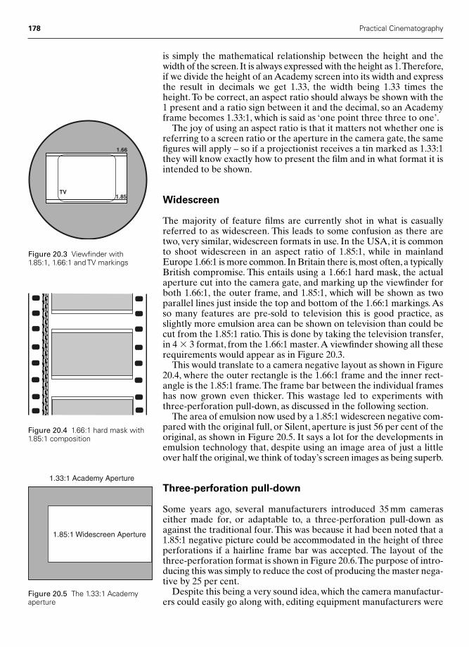
178 Practical Cinematography
is simply the mathematical relationship between the height and thewidth of the screen. It is always expressed with the height as 1.Therefore,if we divide the height of an Academy screen into its width and expressthe result in decimals we get 1.33, the width being 1.33 times theheight. To be correct, an aspect ratio should always be shown with the1 present and a ratio sign between it and the decimal, so an Academyframe becomes 1.33:1, which is said as ‘one point three three to one’.
The joy of using an aspect ratio is that it matters not whether one isreferring to a screen ratio or the aperture in the camera gate, the samefigures will apply – so if a projectionist receives a tin marked as 1.33:1they will know exactly how to present the film and in what format it isintended to be shown.
Widescreen
The majority of feature films are currently shot in what is casuallyreferred to as widescreen. This leads to some confusion as there aretwo, very similar, widescreen formats in use. In the USA, it is commonto shoot widescreen in an aspect ratio of 1.85:1, while in mainlandEurope 1.66:1 is more common. In Britain there is, most often, a typicallyBritish compromise. This entails using a 1.66:1 hard mask, the actualaperture cut into the camera gate, and marking up the viewfinder forboth 1.66:1, the outer frame, and 1.85:1, which will be shown as twoparallel lines just inside the top and bottom of the 1.66:1 markings. Asso many features are pre-sold to television this is good practice, asslightly more emulsion area can be shown on television than could becut from the 1.85:1 ratio. This is done by taking the television transfer,in 4 � 3 format, from the 1.66:1 master.A viewfinder showing all theserequirements would appear as in Figure 20.3.
This would translate to a camera negative layout as shown in Figure20.4, where the outer rectangle is the 1.66:1 frame and the inner rect-angle is the 1.85:1 frame.The frame bar between the individual frameshas now grown even thicker. This wastage led to experiments withthree-perforation pull-down, as discussed in the following section.
The area of emulsion now used by a 1.85:1 widescreen negative com-pared with the original full, or Silent, aperture is just 56 per cent of theoriginal, as shown in Figure 20.5. It says a lot for the developments inemulsion technology that, despite using an image area of just a littleover half the original, we think of today’s screen images as being superb.
Three-perforation pull-down
Some years ago, several manufacturers introduced 35 mm cameraseither made for, or adaptable to, a three-perforation pull-down asagainst the traditional four. This was because it had been noted that a1.85:1 negative picture could be accommodated in the height of threeperforations if a hairline frame bar was accepted. The layout of thethree-perforation format is shown in Figure 20.6.The purpose of intro-ducing this was simply to reduce the cost of producing the master nega-tive by 25 per cent.
Despite this being a very sound idea, which the camera manufactur-ers could easily go along with, editing equipment manufacturers were
1.66
1.85TV
Figure 20.3 Viewfinder with 1.85:1, 1.66:1 and TV markings
Figure 20.4 1.66:1 hard mask with1.85:1 composition
1.33:1 Academy Aperture
1.85:1 Widescreen Aperture
Figure 20.5 The 1.33:1 Academyaperture
Chap-20 2/8/05 11:28 AM Page 178
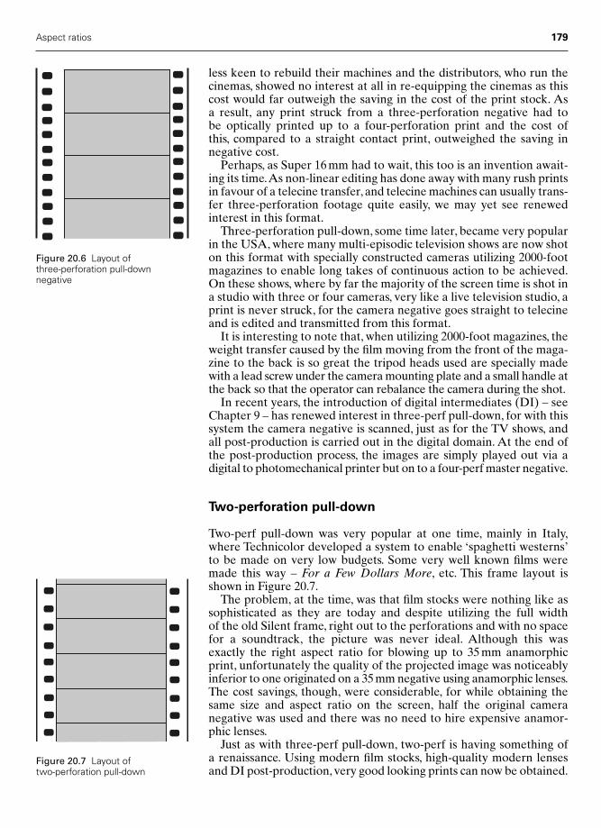
less keen to rebuild their machines and the distributors, who run thecinemas, showed no interest at all in re-equipping the cinemas as thiscost would far outweigh the saving in the cost of the print stock. As a result, any print struck from a three-perforation negative had to be optically printed up to a four-perforation print and the cost of this, compared to a straight contact print, outweighed the saving innegative cost.
Perhaps, as Super 16 mm had to wait, this too is an invention await-ing its time.As non-linear editing has done away with many rush printsin favour of a telecine transfer, and telecine machines can usually trans-fer three-perforation footage quite easily, we may yet see renewedinterest in this format.
Three-perforation pull-down, some time later, became very popularin the USA, where many multi-episodic television shows are now shoton this format with specially constructed cameras utilizing 2000-footmagazines to enable long takes of continuous action to be achieved.On these shows, where by far the majority of the screen time is shot ina studio with three or four cameras, very like a live television studio, aprint is never struck, for the camera negative goes straight to telecineand is edited and transmitted from this format.
It is interesting to note that, when utilizing 2000-foot magazines, theweight transfer caused by the film moving from the front of the maga-zine to the back is so great the tripod heads used are specially madewith a lead screw under the camera mounting plate and a small handle atthe back so that the operator can rebalance the camera during the shot.
In recent years, the introduction of digital intermediates (DI) – seeChapter 9 – has renewed interest in three-perf pull-down, for with thissystem the camera negative is scanned, just as for the TV shows, andall post-production is carried out in the digital domain. At the end ofthe post-production process, the images are simply played out via adigital to photomechanical printer but on to a four-perf master negative.
Two-perforation pull-down
Two-perf pull-down was very popular at one time, mainly in Italy,where Technicolor developed a system to enable ‘spaghetti westerns’to be made on very low budgets. Some very well known films weremade this way – For a Few Dollars More, etc. This frame layout isshown in Figure 20.7.
The problem, at the time, was that film stocks were nothing like assophisticated as they are today and despite utilizing the full width of the old Silent frame, right out to the perforations and with no spacefor a soundtrack, the picture was never ideal. Although this wasexactly the right aspect ratio for blowing up to 35 mm anamorphicprint, unfortunately the quality of the projected image was noticeablyinferior to one originated on a 35 mm negative using anamorphic lenses.The cost savings, though, were considerable, for while obtaining thesame size and aspect ratio on the screen, half the original camera negative was used and there was no need to hire expensive anamor-phic lenses.
Just as with three-perf pull-down, two-perf is having something of a renaissance. Using modern film stocks, high-quality modern lensesand DI post-production, very good looking prints can now be obtained.
Aspect ratios 179
Figure 20.6 Layout of three-perforation pull-downnegative
Figure 20.7 Layout of two-perforation pull-down
Chap-20 2/8/05 11:28 AM Page 179

This might mean more first time film-makers, and even film schools,could afford to shoot for anamorphic projection – an exciting thought.
Anamorphic
In order to give First World War tank drivers a better view, a Frenchphysicist, Henri Chretien, developed a lens system that was capable of expanding and compressing the horizontal angle of view. Thisdeveloped into a single Hypergonar lens capable of being fitted to afilm camera and a picture, Construire un Feu, was shot in France usingjust this one lens. By the beginning of the 1950s,American film-makershad come to the conclusion that providing cinemas with wider and widerscreens was the answer to getting the audiences out of their houses andaway from their television sets. In order not to increase costs appre-ciably, 20th Century Fox adopted and developed Chretien’s principlesto produce a range of lenses, of various focal lengths, capable of shoot-ing a film in a convenient way, on conventional 35 mm film stock butwith just a change of camera and cinema projector lenses.This resultedin an aspect ratio of well in access of 2:1. This system they namedCinemaScope and it was very successful, being the first worldwideanamorphic process (anamorphos from the Greek ana � again,morphos � to form).
The horizontal compression of the CinemaScope format was 2:1.This gave CinemaScope an aspect ratio, when the 35 mm camera frame(0.868 in. � 0.631 in.) was expanded by the special lens, of 2.55:1.Pressure from the cinema owners caused this to be reduced to a standardof 2.35:1, mainly due to the architectural constraints of many existingcinemas; this was often reduced still further on showing, for the samereasons.
Figure 20.8 shows how the image is managed. The original scene ishorizontally compressed by a ratio of 2:1 by the taking lens. This isthen contact printed without any optical modification. When the printis shown in the cinema, the projector lens expands the image horizon-tally by the same ratio of 2:1 and the image is restored on the screen inthe original height-to-width relationship.
In the early days of anamorphic photography, no compensation wasmade in the camera viewfinder and the operator had to compose theframe with the image compressed to half its actual width. Mercifully,most modern cameras capable of accepting anamorphic lenses canalso be supplied with a de-anamorphosing viewfinder, so that theoperator can view the image as the audience will see it. That the earlyoperators could compose such wonderful images with a squeezedimage fills me with admiration.
65 mm and 70 mm
In compressing and expanding the camera image with the anamorphicprocess, some horizontal definition is lost. To counteract this, severalcompanies decided to shoot very wide screen pictures without a compression lens but using wider film. The Panavision company isprobably the best known of the exponents of this format. Todd-AO,
180 Practical Cinematography
Chap-20 2/8/05 11:28 AM Page 180

a name conjured from Richard Todd and the American OpticalCompany who made lenses for him, must be a close contender. In boththese systems a 65 mm camera negative is employed using standard35 mm perforations but utilizing five-perforation pull-down. With allthe other layout dimensions remaining similar to 35 mm and the imagegoing out to the perforations on both sides, no provision for sound ismade on the camera negative. This gives an image aspect ratio of2.21:1.This aspect ratio is very close to CinemaScope’s, but by utilizinga far larger image area gives considerably improved image quality. Italso enables simple, spherical (non-anamorphic) lenses to be used.
In order to deliver sound to the cinemas, the 65 mm camera negativeis printed on to 70 mm wide print stock. So that the image can still becontact printed, both films have their perforations, and images, in iden-tical positions, the extra width coming as 2.5 mm outside each row ofperforations.This extra 5 mm of film accommodates the various soundand control tracks. Figure 20.9 shows the layout of both the 65 mmnegative and the 70 mm print.
There are hybrid systems where, for reasons of origination cost, theanamorphic process is used to make a 35 mm camera negative and this
Aspect ratios 181
OriginalScene
Anamorphic Negative
Anamorphic Print
Cinema Screen
Anamorphic Projector Lens
Anamorphic Taking Lens
Figure 20.8 The anamorphicprocess
Chap-20 2/8/05 11:28 AM Page 181

is then optically expanded using a de-anamorphosing lens in the labora-tory printer to produce a 70 mm release print. It is quite common for afilm shot on a 35 mm anamorphic system to have a few release printsmade on 70 mm for the premieres around the world and still make themajority of general release prints as 35 mm anamorphic prints. Clearly,this makes for a considerable cost saving.
It is also possible to take the reverse route and shoot on a 65 mmnegative, make the premiere prints on 70 mm stock and still make thegeneral release prints as 35 mm anamorphic prints, though the costsavings using this route are nothing like as great.
Super 35
This much-vaunted format, where you get a larger than Academyframe and can use existing spherical lenses, is effectively a return tothe old Silent layout. With modern film stocks it is quite possible toprint a 2.21:1 section from the middle of the frame and send it to thecinema either as a squeezed anamorphic print or enlarge it to 70 mm.The advantages in cost savings at the time of exposure are somewhatoffset by the cost of optical printing to the delivery format.
For the camera operator, Super 35 can be a nightmare. In Figure 20.10you can see what ought to be a simple two-shot, here composed cor-rectly for the inner frame, which is 2.21:1. If, as many a producer maywish, another copy is struck for television, here shown by the largerrectangle with curved corners, the composition becomes a nonsense.The claim that you can shoot full frame and choose any aspect ratiolater, from a compositional point of view, is clearly erroneous.
182 Practical Cinematography
65 mm Camera Negative
70 mm Release Print with Sound Tracks
Figure 20.9 The 65 mm negativeand a 70 mm print
Figure 20.10 The layout of theSuper 35 frame
Chap-20 2/8/05 11:28 AM Page 182
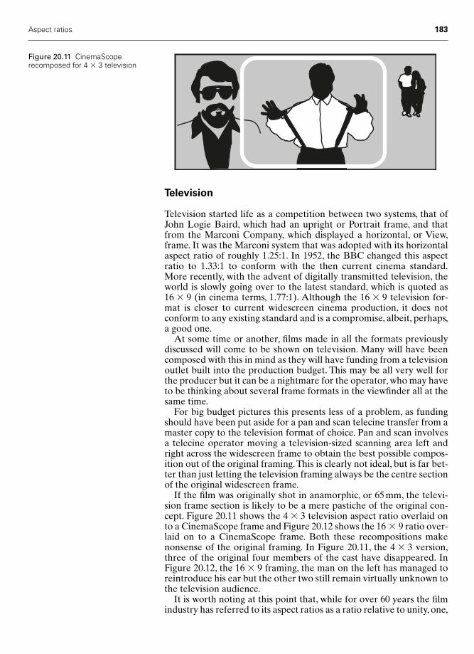
Television
Television started life as a competition between two systems, that ofJohn Logie Baird, which had an upright or Portrait frame, and thatfrom the Marconi Company, which displayed a horizontal, or View,frame. It was the Marconi system that was adopted with its horizontalaspect ratio of roughly 1.25:1. In 1952, the BBC changed this aspectratio to 1.33:1 to conform with the then current cinema standard.More recently, with the advent of digitally transmitted television, theworld is slowly going over to the latest standard, which is quoted as16 � 9 (in cinema terms, 1.77:1). Although the 16 � 9 television for-mat is closer to current widescreen cinema production, it does notconform to any existing standard and is a compromise, albeit, perhaps,a good one.
At some time or another, films made in all the formats previouslydiscussed will come to be shown on television. Many will have beencomposed with this in mind as they will have funding from a televisionoutlet built into the production budget. This may be all very well forthe producer but it can be a nightmare for the operator, who may haveto be thinking about several frame formats in the viewfinder all at thesame time.
For big budget pictures this presents less of a problem, as fundingshould have been put aside for a pan and scan telecine transfer from amaster copy to the television format of choice. Pan and scan involvesa telecine operator moving a television-sized scanning area left andright across the widescreen frame to obtain the best possible compos-ition out of the original framing.This is clearly not ideal, but is far bet-ter than just letting the television framing always be the centre sectionof the original widescreen frame.
If the film was originally shot in anamorphic, or 65 mm, the televi-sion frame section is likely to be a mere pastiche of the original con-cept. Figure 20.11 shows the 4 � 3 television aspect ratio overlaid onto a CinemaScope frame and Figure 20.12 shows the 16 � 9 ratio over-laid on to a CinemaScope frame. Both these recompositions makenonsense of the original framing. In Figure 20.11, the 4 � 3 version,three of the original four members of the cast have disappeared. InFigure 20.12, the 16 � 9 framing, the man on the left has managed toreintroduce his ear but the other two still remain virtually unknown tothe television audience.
It is worth noting at this point that, while for over 60 years the filmindustry has referred to its aspect ratios as a ratio relative to unity, one,
Aspect ratios 183
Figure 20.11 CinemaScoperecomposed for 4 � 3 television
Chap-20 2/8/05 11:28 AM Page 183

the television industry has always referred to its aspect ratios as thenearest whole numbers representing height and width times each other.
Things are not quite as bad when taking a television scan from thecentre section of a widescreen negative that has been shot with a1.66:1 hard mask in the camera gate but was framed for theatricalrelease in the 1.85:1 aspect ratio.As we have seen, the television framecan be taken from the 1.66:1 frame, thus gaining both height and, moreimportantly, width of frame and getting nearer to the original compos-ition. Figure 20.13 shows a 4 � 3 television frame overlaid on a 1.66:1original, while Figure 20.14 shows the same but for a 16 � 9 televisiontransfer.
184 Practical Cinematography
Figure 20.12 CinemaScoperecomposed for 16 � 9 television
Figure 20.13 The 1.66:1, 1.85:1 and the television 4 � 3 aspect ratios
Figure 20.14 The 1.66:1, 1.85:1 and the television 16 � 9 aspect ratios
Chap-20 2/8/05 11:28 AM Page 184

The technique of shooting a negative in the ratio of 1.66:1 and tak-ing the television frame from this whilst still intending to show the1.85:1 frame in the cinema relies on the operator using a techniqueknown as shoot and protect. This requires the camera operator toshoot the primary composition for 1.85:1 while protecting the 1.66:1frame. Protecting, in this instance, means being absolutely certain thatthe 1.66:1 frame never shoots off the set, that microphones neverintrude into this frame and nothing that does not relate to the storyenters this, the outer, frame.The technique of shoot and protect is usedin many other cross-format situations and, providing not too manyformats are required, is not too arduous for the operator and can bevery successful.
When shooting Super 16 mm for television, matters are a little com-plicated as the world has still not gone over completely to the 16 � 9television format; therefore, within the frame, allowances may have tobe made to accommodate a 16 � 9 composition, a 4 � 3 compositionand even an interim format of 14 � 9 as used on UK analogue transmissions at present.
Aspect ratios 185
Chap-20 2/8/05 11:28 AM Page 185

This page intentionally left blank

Part Five
The Future
Chap-21 2/8/05 11:30 AM Page 187

This page intentionally left blank

21
Aspect ratios whenshooting for television
The nature of the problem
There has been a problem in recent years as to how to ‘future-proof’television programmes that might be transmitted in the old 4 � 3 aspectratio but will, at some time, need to be repeated in the intermediate14 � 9 aspect ratio or, eventually, in the 16 � 9 aspect ratio that hasbecome the new international standard.
The whole argument should really be turned on its head, as bothSuper 16 mm film cameras and Digi Beta cameras happily shoot in anaspect ratio either exactly, or very close to, the 16 � 9 aspect ratio.Therefore, the true problem is ‘now-proofing’. Most television pro-grammes are almost all now originated in the 16 � 9 aspect ratio;therefore, the difficult decision is which compromise aspect ratio totransmit now on the gradually disappearing 4 � 3 standard.
It is interesting to look at the history of the 16 mm format, as thisshows how the Super 16 mm standard, which was developed many yearsago, has found its true value in recent years as an ideal format for shoot-ing high-quality television; this is particularly true in the UK.
History – the evolution of the Super 16 mm format
In the early 1920s George Eastman, the founder of Kodak, together withthe Bell & Howell company of Chicago, Illinois, set out to develop anamateur film standard, and a camera and projector to go with it. Bell &Howell favoured a 17.5 mm film, this being the standard 35 mm filmsimply slit in two. George Eastman objected strongly. He was adamantthat a completely new standard was required because, up until then,the film base was nitrate and was very prone to bursting into flames.He was determined that the amateur film should only ever be avail-able on the new ‘Safety’ film base and to ensure this there had to be anew standard. Eastman simply could not abide the idea of his newproduct being responsible for burning down a customer’s home. Bell &Howell were not entirely happy, as one of their major patents wasfor the standard 35 mm sprocket hole, which would have been usedagain on 17.5 mm, though now only on one side of the film. GeorgeEastman prevailed though, very much to our current benefit.
189
Chap-21 2/8/05 11:30 AM Page 189
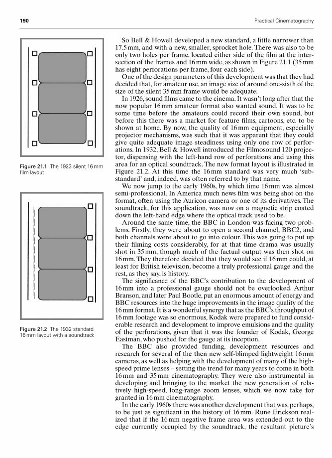
So Bell & Howell developed a new standard, a little narrower than17.5 mm, and with a new, smaller, sprocket hole. There was also to beonly two holes per frame, located either side of the film at the inter-section of the frames and 16 mm wide, as shown in Figure 21.1 (35 mmhas eight perforations per frame, four each side).
One of the design parameters of this development was that they haddecided that, for amateur use, an image size of around one-sixth of thesize of the silent 35 mm frame would be adequate.
In 1926, sound films came to the cinema. It wasn’t long after that thenow popular 16 mm amateur format also wanted sound. It was to besome time before the amateurs could record their own sound, butbefore this there was a market for feature films, cartoons, etc. to beshown at home. By now, the quality of 16 mm equipment, especiallyprojector mechanisms, was such that it was apparent that they couldgive quite adequate image steadiness using only one row of perfor-ations. In 1932, Bell & Howell introduced the Filmosound 120 projec-tor, dispensing with the left-hand row of perforations and using thisarea for an optical soundtrack. The new format layout is illustrated inFigure 21.2. At this time the 16 mm standard was very much ‘sub-standard’ and, indeed, was often referred to by that name.
We now jump to the early 1960s, by which time 16 mm was almostsemi-professional. In America much news film was being shot on theformat, often using the Auricon camera or one of its derivatives. Thesoundtrack, for this application, was now on a magnetic strip coateddown the left-hand edge where the optical track used to be.
Around the same time, the BBC in London was facing two prob-lems. Firstly, they were about to open a second channel, BBC2, andboth channels were about to go into colour. This was going to put uptheir filming costs considerably, for at that time drama was usuallyshot in 35 mm, though much of the factual output was then shot on16 mm. They therefore decided that they would see if 16 mm could, atleast for British television, become a truly professional gauge and therest, as they say, is history.
The significance of the BBC’s contribution to the development of16 mm into a professional gauge should not be overlooked. ArthurBranson, and later Paul Bootle, put an enormous amount of energy andBBC resources into the huge improvements in the image quality of the16 mm format. It is a wonderful synergy that as the BBC’s throughput of16 mm footage was so enormous, Kodak were prepared to fund consid-erable research and development to improve emulsions and the qualityof the perforations, given that it was the founder of Kodak, GeorgeEastman, who pushed for the gauge at its inception.
The BBC also provided funding, development resources andresearch for several of the then new self-blimped lightweight 16 mmcameras, as well as helping with the development of many of the high-speed prime lenses – setting the trend for many years to come in both16 mm and 35 mm cinematography. They were also instrumental indeveloping and bringing to the market the new generation of rela-tively high-speed, long-range zoom lenses, which we now take forgranted in 16 mm cinematography.
In the early 1960s there was another development that was, perhaps,to be just as significant in the history of 16 mm. Rune Erickson real-ized that if the 16 mm negative frame area was extended out to theedge currently occupied by the soundtrack, the resultant picture’s
190 Practical Cinematography
Figure 21.1 The 1923 silent 16 mmfilm layout
Figure 21.2 The 1932 standard16 mm layout with a soundtrack
Chap-21 2/8/05 11:30 AM Page 190
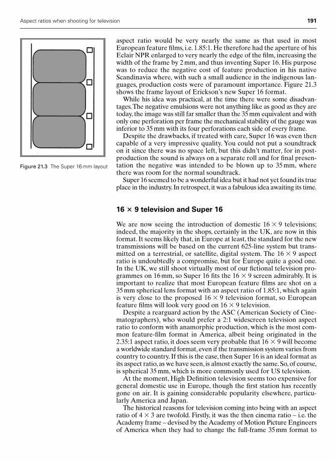
aspect ratio would be very nearly the same as that used in mostEuropean feature films, i.e. 1.85:1. He therefore had the aperture of hisEclair NPR enlarged to very nearly the edge of the film, increasing thewidth of the frame by 2 mm, and thus inventing Super 16. His purposewas to reduce the negative cost of feature production in his nativeScandinavia where, with such a small audience in the indigenous lan-guages, production costs were of paramount importance. Figure 21.3shows the frame layout of Erickson’s new Super 16 format.
While his idea was practical, at the time there were some disadvan-tages.The negative emulsions were not anything like as good as they aretoday, the image was still far smaller than the 35 mm equivalent and withonly one perforation per frame the mechanical stability of the gauge wasinferior to 35 mm with its four perforations each side of every frame.
Despite the drawbacks, if treated with care, Super 16 was even thencapable of a very impressive quality. You could not put a soundtrackon it since there was no space left, but this didn’t matter, for in post-production the sound is always on a separate roll and for final presen-tation the negative was intended to be blown up to 35 mm, wherethere was room for the normal soundtrack.
Super 16 seemed to be a wonderful idea but it had not yet found its trueplace in the industry. In retrospect, it was a fabulous idea awaiting its time.
16 � 9 television and Super 16
We are now seeing the introduction of domestic 16 � 9 televisions;indeed, the majority in the shops, certainly in the UK, are now in thisformat. It seems likely that, in Europe at least, the standard for the newtransmissions will be based on the current 625-line system but trans-mitted on a terrestrial, or satellite, digital system. The 16 � 9 aspectratio is undoubtedly a compromise, but for Europe quite a good one.In the UK, we still shoot virtually most of our fictional television pro-grammes on 16 mm, so Super 16 fits the 16 � 9 screen admirably. It isimportant to realize that most European feature films are shot on a35 mm spherical lens format with an aspect ratio of 1.85:1, which againis very close to the proposed 16 � 9 television format, so Europeanfeature films will look very good on 16 � 9 television.
Despite a rearguard action by the ASC (American Society of Cine-matographers), who would prefer a 2:1 widescreen television aspectratio to conform with anamorphic production, which is the most com-mon feature-film format in America, albeit being originated in the2.35:1 aspect ratio, it does seem very probable that 16 � 9 will becomea worldwide standard format, even if the transmission system varies fromcountry to country. If this is the case, then Super 16 is an ideal format asits aspect ratio, as we have seen, is almost exactly the same. So, of course,is spherical 35 mm, which is more commonly used for US television.
At the moment, High Definition television seems too expensive forgeneral domestic use in Europe, though the first station has recentlygone on air. It is gaining considerable popularity elsewhere, particu-larly America and Japan.
The historical reasons for television coming into being with an aspectratio of 4 � 3 are twofold. Firstly, it was the then cinema ratio – i.e. theAcademy frame – devised by the Academy of Motion Picture Engineersof America when they had to change the full-frame 35 mm format to
Aspect ratios when shooting for television 191
Figure 21.3 The Super 16 mm layout
Chap-21 2/8/05 11:30 AM Page 191
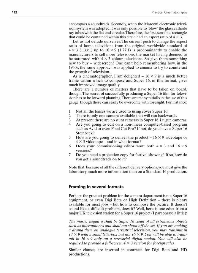
encompass a soundtrack. Secondly, when the Marconi electronic televi-sion system was adopted it was only possible to ‘blow’ the glass cathoderay tubes with the flat end circular.Therefore, the first, sensible, rectanglethat could be contained within this circle had an aspect ratio of 4 � 3.
Let us not delude ourselves. The current push to change the aspectratio of home televisions from the original worldwide standard of4 � 3 (1.33:1) up to 16 � 9 (1.77:1) is predominantly to enable themanufacturers to sell more televisions, the market having deemed tobe saturated with 4 � 3 colour televisions. So give them somethingnew to buy – widescreen! One can’t help remembering how, in the1950s, the same approach was applied to cinema to try to counteractthe growth of television.
As a cinematographer, I am delighted – 16 � 9 is a much betterframe within which to compose and Super 16, in this format, givesmuch improved image quality.
There are a number of matters that have to be taken on board,though. The secret of successfully producing a Super 16 film for televi-sion has to be forward planning.There are many pitfalls in the use of thisgauge, though these can easily be overcome with foresight. For instance:
1 Not all the lenses we are used to using cover Super 16.2 There is only one camera available that will run backwards.3 At present there are no stunt cameras in Super 16, i.e. gun cameras.4 Are you going to edit on a non-linear computer-based program
such as Avid or even Final Cut Pro? If not, do you have a Super 16Steinbeck?
5 How are you going to deliver the product – 16 � 9 videotape or4 � 3 videotape – and in what format?
6 Does your commissioning editor want both 4 � 3 and 16 � 9 versions?
7 Do you need a projection copy for festival showing? If so, how doyou get a soundtrack on to it?
Note that, because of all the different delivery options, you must give thelaboratory much more information than on a Standard 16 production.
Framing in several formats
Perhaps the greatest problem for the camera department is not Super 16equipment, or even Digi Beta or High Definition – there is plentyavailable for most jobs – but how to compose the picture. It doesn’tsound like a difficult problem, does it? Well, here is one edict from amajor UK television station for a Super 16 project (I paraphrase a little):
The master negative shall be Super 16 clean of all extraneous objectssuch as microphones and shall not shoot off the set. If you are makinga drama then, on analogue terrestrial television, you may transmit in14 � 9 with a small letterbox but not 16 � 9. You will be able to trans-mit in 16 � 9 only on a terrestrial digital station. You will also berequired to provide a full-screen 4 � 3 version for foreign sales.
Similar clauses are inserted in contracts for Digi Beta and HD productions.
192 Practical Cinematography
Chap-21 2/8/05 11:30 AM Page 192

Let us take some examples to demonstrate the problem. In Figure 21.4 we have a well-composed 16 � 9 scene – the cloisters of auniversity with two undergraduates shaking hands on the right-handside of the frame.
Over this I have shown a 16 � 9 or Super 16 frame. All is well at this point and we have a very nice composition with a good dynamiccomposition.
If we now recompose the centre section, as is the norm, for 14 � 9,we see – in Figure 21.5 – just what we would be transmitting. It reallyis not acceptable. One undergraduate has nearly disappeared out ofthe right-hand side of the frame and no one in their right mind wouldhave made an original composition in this way. I am sure, though,there would be many non-production executives who would find thisacceptable if only because the cost of pan and scanning the original tocorrect the composition would, in their eyes, be prohibitive.
Aspect ratios when shooting for television 193
Figure 21.4 A well-composed16 � 9 frame
Figure 21.5 A 14 � 9 sectionfrom the middle of a 16 � 9frame
Chap-21 2/8/05 11:30 AM Page 193

But now let us look at what the purchasers of the programme forviewing abroad have to put up with. In Figure 21.6 I have shown thesame scene with the 4 � 3 centre section recomposed. One under-graduate has now completely disappeared.
This really is a ridiculous situation. If we were to frame the originalfor 4 � 3, then the 14 � 9 UK transmission will lose all the power of theframe and in a 16 � 9 frame there will be no dynamic to the frame at all,as the two undergraduates will now be very nearly in the middle of theframe, a very boring composition. Do we really want to descend to thislevel of artistry in the name of future-proofing? Our real problem, atleast until 16 � 9 televisions take over completely, is ‘now-proofing’.
Here I must make a plea to the production office. Let us imagineyou have had your initial transmission and you are sitting back review-ing your great success.A call comes from the foreign sales departmentand you order a 4 � 3 copy. Seems simple, doesn’t it? Now withoutfurther information your telecine operator is quite likely to assumeyou mean the old 4 � 3 and put it up on a Standard 16 telecine. It’s nothis fault, and please don’t shout at him – you should have asked forCentre Section Super 16 transfer to 4 � 3.
If you don’t, then the result will be as in Figure 21.7, since he will clipoff the left-hand side of the film – the right-hand side of the screen –and both undergraduates vanish!
Framing solutions
If you are lucky enough to be shooting for the UK Channel 4, then youare very fortunate. They currently are quite happy to transmit dramain true 16 � 9, even on their whole output – with the appropriate letterbox – and are heavily committed to the future of a European16 � 9 format. In fact, they seem to be the only channel so totally com-mitted on any analogue station in the UK.
When shooting for many stations across the world you have to deliverin three formats. The current position in the UK seems to be that they
194 Practical Cinematography
Figure 21.6 A 4 � 3 section fromthe middle of a 16 � 9 frame
Chap-21 2/8/05 11:30 AM Page 194

assume fiction will be transmitted 14 � 9, but might be persuaded totransmit 16 � 9. It is important to recognize the word ‘deliver’ – thingswill change as the UK goes over to digital 16 � 9; only then will we beallowed to truly realize the artistic potential of the 16 � 9 format.
The important thing, therefore, is to establish in what aspect ratioyour primary transmission will be and in what other aspect ratios youmust deliver, and come to an agreed compromise before you startshooting. A change of mind later can be both unpleasant to look atand very expensive.
My own position is that I would prefer to make the best compos-ition for the primary transmission format – if this were 14 � 9, thenthe composition would now look like Figure 21.8. But I would ask fora budget to make a pan and scan transfer to any narrower format. I
Aspect ratios when shooting for television 195
Figure 21.7 A 4 � 3 Standard 17telecine transfer from a Super 16negative
Figure 21.8 An ‘ideal’ 14 � 9composition
Chap-21 2/8/05 11:30 AM Page 195

also make every effort to ensure that I attend that transfer. Figure 21.9shows how 16 � 9, 14 � 9 and 4 � 3 would look using this principle.
Therefore, if this composition were later transmitted on a full format16 � 9 system, then it would look like the white outline in Figure 21.9.Not fantastic, but very acceptable, for putting the undergraduates onthe edge of this frame, as in Figure 21.6, has more impact. The mid-grey outline is the primary composition; 14 � 9 and the light grey out-line would be the pan and scan 4 � 3 version, also very acceptable.
Without pan and scan the foreign sales version would look likeFigure 21.10 – which is still unacceptable.
On the other hand, let us assume that the producers have retainedsufficient funds for a pan and scan transfer and have invited the cine-matographer to supervise it. What a difference this would make. Anyforeign purchaser would not only be pleased with the framing of
196 Practical Cinematography
Figure 21.9 A 14 � 9 compositionon a 16 � 9 frame with 4 � 3 framepan and scanned
Figure 21.10 A 4 � 3 frame panand scanned from 14 � 9composition
Chap-21 2/8/05 11:30 AM Page 196
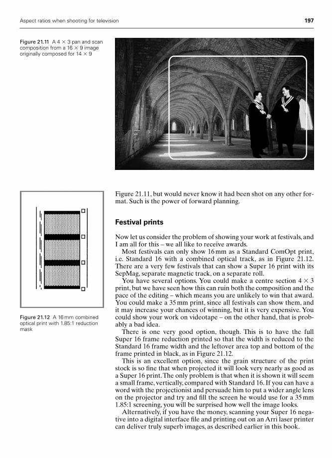
Figure 21.11, but would never know it had been shot on any other for-mat. Such is the power of forward planning.
Festival prints
Now let us consider the problem of showing your work at festivals, andI am all for this – we all like to receive awards.
Most festivals can only show 16 mm as a Standard ComOpt print,i.e. Standard 16 with a combined optical track, as in Figure 21.12.There are a very few festivals that can show a Super 16 print with itsSepMag, separate magnetic track, on a separate roll.
You have several options. You could make a centre section 4 � 3print, but we have seen how this can ruin both the composition and thepace of the editing – which means you are unlikely to win that award.You could make a 35 mm print, since all festivals can show them, andit may increase your chances of winning, but it is very expensive. Youcould show your work on videotape – on the other hand, that is prob-ably a bad idea.
There is one very good option, though. This is to have the full Super 16 frame reduction printed so that the width is reduced to theStandard 16 frame width and the leftover area top and bottom of theframe printed in black, as in Figure 21.12.
This is an excellent option, since the grain structure of the printstock is so fine that when projected it will look very nearly as good asa Super 16 print.The only problem is that when it is shown it will seema small frame, vertically, compared with Standard 16. If you can have aword with the projectionist and persuade him to put a wider angle lenson the projector and try and fill the screen he would use for a 35 mm1.85:1 screening, you will be surprised how well the image looks.
Alternatively, if you have the money, scanning your Super 16 nega-tive into a digital interface file and printing out on an Arri laser printercan deliver truly superb images, as described earlier in this book.
Aspect ratios when shooting for television 197
Figure 21.11 A 4 � 3 pan and scancomposition from a 16 � 9 imageoriginally composed for 14 � 9
Figure 21.12 A 16 mm combinedoptical print with 1.85:1 reductionmask
Chap-21 2/8/05 11:30 AM Page 197
22
High Definition – HD
Is film dead?
No, most certainly not!Over the past few years I have been closely connected with the
introduction of HD and, while I believe the pictures can be wonderful,the reasons for choosing to shoot with HD, as opposed to film, are notas numerous as it first appeared.
Three-chip cameras
The first wave of HD cameras with their three-chip configurationwere, and indeed still are, able to emulate the quality of image obtain-able when using 35 mm film, but only if you used the finest lenses.Many so-called HD lenses produced a picture nowhere near the cam-era’s capability, which caused the cameras to get a mixed reception.Those that saw demonstration films shot with top quality lenses, suchas Panavision’s, were usually impressed and those that saw materialfrom poorer glass were usually disappointed.
In some areas the HD three-chip format was very successful. Forinstance, within three years of the introduction of HD, nearly half themulti-episodic, multi-camera shoots for US television were shot usingHD. Here the attraction is clear, with quality virtually the same as thethree-perforation pull-down 35 mm cameras that have traditionallybeen used to shoot these shows, and recording medium costing aroundone-fortieth the price (yes, 1/40!), the sums really worked in HD’sfavour.
Star Wars – Attack of the Clones, the first full-length feature film shoton HD – looked very good indeed. Photographed by David TattersallBSC, I could hardly tell if I was watching a mechanically projectedprint or a digitally projected image, and both versions were excellent.George Lucas, it is said, prefers the digital version. But why shoot apicture costing over $1 000 000 on HD? Surely not to save money – no,here the advantage was the ability to go straight from the camera mas-ter image directly to the computers that would be used for the huge
198
Chap-22 12/16/04 3:21 PM Page 198

Practical Cinematography 199
amount of image post-production without leaving the digital domain.The need to carry out a lot of digital post-production is a powerfulargument for originating on HD.
Single-chip cameras
Matters have moved forward and several manufacturers have intro-duced single-chip cameras, where the chip is approximately the size ofthe frame used in 35 mm photography and some of them have, effect-ively, twice the resolution of the first generation three-chip cameras.Perhaps the greatest advantage of these cameras is their use of exactlythe same lenses as 35 mm film cameras. It remains to be seen if thesecameras will increase the popularity of shooting feature films in thedigital format.
Digital presentation
There are clear financial advantages for the distributors of featurefilms if cinemas are equipped with digital projectors of sufficient qual-ity such that the audience are unaware of the change from mechanicalto digital projectors.The savings come in some surprising places. In thedistribution chain, it is said that the cost of transporting film prints, i.e.vans etc., from theatre to theatre is more than the cost of producingthe prints themselves. If this is the case, were it possible to deliver thevirtual digital image by, say, fibre-optic or satellite, a large cost of deliver-ing the images to the cinema would be saved.
The other side of the distribution dilemma is interesting, as the dis-tributors do not own the projectors: the exhibitors own the cinemasand the projectors, so the cost of conversion would fall on the shoul-ders of the exhibitors, who are unlikely to make any extra profit fromthe change-over. Currently, the comparable price of a digital projectorable to give a picture of comparable quality to a mechanical projectoris substantial, an HD projector costing some three times as much asthe mechanical equivalent.
Conclusions
HD digital cinema, I believe, is bound to come but I suspect slowly, asthere are many obstacles to overcome, though few of these are of a tech-nical nature – all the required delivery systems and projection equip-ment are available today. It will need an important agreement betweenthe distributors and the exhibitors for the revolution to happen.
There will be some films that will cry out to be shot in the digital HDformat and others that will not. Futuristic and hyper-realistic movies,together with those requiring a lot of digital post-production, will bewell suited to HD, though I believe that for many years to come themore human story-based movies will still shoot on film.Why? Becausethere is over 100 years of history and knowledge in how to stir theemotions of an audience, via their eyes, that lies vested in that peculiarcontrolled rotting of silver. We Directors of Photography have beensuccessfully giving our audience pictures they love, and know how toemote to, on film for those 100 years or so – long may it continue.
Chap-22 12/16/04 3:21 PM Page 199

This page intentionally left blank

Aaton cameras, 48, 102–3Aberration, chromatic, 60–1Academy aperture, 177Acid stop bath, 67Anamorphic photography, 180Aperture:
depth of field and, 139maximum, 53–4
Arri Laser Printer, 92Arriflex cameras, 44, 102ASA film speed, 79Aspect ratios, 177–85
65 mm, 180–170 mm, 180–2anamorphic, 180for television, 183–5, 189–97Super 35, 182three-perforation pull-down,
178–9two-perforation pull-down,
179–80widescreen, 178
Average scene reflectance values, 102
Avid process, 75
Backlight board, 27–9, 155–6Barrel distortion, 59Base level fog, 81Batch number, 74Battery testing, 153BBC, 190Bell and Howell, 72–3, 189–90
Model C printer, 83Best boy, 33Binary code, 93–4Bootle, Paul, 190Branson, Arthur, 190Butterfly shutter, 40
Calotype, 63Camera, 37–48
built-in exposure meters, 102–3
equipment list, 10–11film camera layout, 47–8film magazine, 45–6frame rates, 38–9, 101high definition (HD) cameras,
198–9intermittent mechanism, 39–43
claw, 41–2film gate, 40–1loop, 42–3shutter, 40
reflex viewfinder, 43–4viewing screens, 45
Camera car, 156Camera crew, 24–33
clapper loader, 25–9crew protocol, 33Director of Photography (DP),
3–6, 31–2focus puller, 30–1gaffer, 33grip, 32–3operator, 31trainee, 24–5
Camera equipment list, 10–11Camera placement, 171Camera report sheet, 27Camera steady tests, 147–8Canon lenses, 50, 56Characteristic curve, 77–9Chromatic aberration, 60–1Cinema release prints, 87–8CinemaScope, 180, 181, 183Circles of confusion, 135–7,
138–9Clapper board, 27–9, 155Clapper loader, 25–9Claw, 41–2Coaxial film magazine, 46Colour changes, 117–18Colour compensating (CC) filters,
122–3, 128Colour correction, 121–3, 126–7
201
Index
Index 12/16/04 3:22 PM Page 201

Colour correction (contd)colour-correction filters, 121–3,
128–9fluorescent light correction,
132tungsten light correction, 126
grey card use, 117–18Colour film, 69–71, 124–6Colour temperature, 120–1Colour temperature meter, 123–4Combined exposure meter, 105–6Completion bond, 146Composition:
complex and combinedcomposition, 163–5
diagonal framing, 163framing in several formats, 163–5,
192–4framing solutions, 194–7rule of thirds, 159–62sixths, 162–3
Contact printing, 84Contrast, 79–81
low contrast filters, 130perceived sharpness and, 50–3ultra contrast filters, 130
Cooke lenses, 49–50, 55, 56, 61S4 lenses, 58–9
Coral filters, 129Cup bat, 25
Daylight, 125–6Definition, 107
high definition (HD) cameras,198–9
Depth of field, 135–4535 mm film, when only shown on
television, 138aperture effect on, 139calculators, 142–5focal length effect on, 139–41mathematics of, 141–2Super 16 mm film, 138–9
Super 16 to 35 mm blow-upsand, 137–8
Depth of focus, 135Desaturation, 117–18Developer, 66Diagonal framing, 163Digital calculators, 144–5Digital images, 93Digital intermediates (DI), 91, 92–3
16 mm DI route, 97binary code, 93–4deliverables, 97image acquisition, 96–7linear and logarithmic sampling,
94–6reasons for using digital, 92–3resolution, 96–7
Digital presentation, 199Director of Photography (DP), 3–6
preparation for shoot, 9–10responsibilities, 3–6, 31–2
Displacement film magazine,45–6
Distortion, 59–61barrel, 59chromatic aberration, 60–1effect of, 59–60pincushion, 59
Dolly, 32–3Double fog filters, 131
Eastman, George, 63, 189–90Edge numbers, 74–5Edit Decision List (EDL), 86–7,
88–9Emulsions, 62, 64
contact printing, 84panchromatic, 133sensitometry, 77–81
Enhancing filters, 132Equipment lists:
camera equipment, 10–11lighting equipment, 11–12
Erickson, Rune, 190–1Eubank, David, 145Exposure latitude, 111–12Exposure meters, 101–6
built-in camera meters, 102–3combined meter, 105–6incident light meters, 103–4reflected light meters, 103spot meters, 104–5
Exposure Values (EVs), 105Eye focus, 30
f numbers, 140Festival prints, 197Film camera layout, 47–8Film gate, 40–1Film grading, 90Film magazine, 45–6Film speed, 79Film stock, 62–76
breakdown, 17–23care, shipping and handling, 75–6colour negative film, 69–71edge numbers, 74–5grain, 71perforations, 72–4photographic process, 63–8
history of, 62–3sensitometry, 77–81
characteristic curve, 77–9contrast, 79–81film speed, 79
Filter factors, 133Filters, 121–3, 128–34
202 Index
Index 12/16/04 3:22 PM Page 202

colour-compensating (CC) filters,122–3, 128
colour-correction filters, 121–3,128–9
coral, 129enhancing, 132fluorescent light correction, 132fog filters, 130–1
double fog, 131graduated, 129–30low contrast, 130matching shots, 132nets, 131–2neutral density, 130pan glass, 133–4polar screens, 132–3pro-mist filters, 131sepia, 129skin tone warmer, 129star filters, 131ultra contrast, 130
Fixer, 67Flare, 85–6Fluorescent light correction
filters, 132Focal length:
depth of field and, 139–41emotional involvement and,
171–5camera placement, 171keeping the audience at arm’s
length, 172subjective and objective shots,
172–5frame size and, 166–7normal focal length lenses, 176
Focus puller, 30–1Focus tests, 152–3Fog filters, 130–1
double fog, 131Fog tests, 150Fox Talbot, William Henry, 62–3Frame leader, 148–9Frame rates, 38–9, 101
television, 39, 101Frame size, focal length and,
166–7Framing:
diagonal framing, 163in several formats, 163–5, 192–4rule of thirds, 159–62sixths, 162–3solutions, 194–7
Full aperture, 177Full negative, 32
Gaffer, 33Gamma, 79–81
testing, 153Gelatine support medium, 63, 64
Graduated filters, 129–30Grain, 71
acceptable levels of, 72Grey card, 115–19
as a messenger to laboratory, 115controlling print density, 116–17developments in, 118–19intentional colour changes,
117–18shifting colour, 117
Grip, 32–3Guild calculator, 142–3
H and D curve, 77–9Hair in the gate (HIG), 26Head testing, 154Herschel, Sir John, 62, 67High definition (HD) television,
191, 198–9digital presentation, 199single-chip cameras, 199three-chip cameras, 198–9
Hyperfocal distance, 141–2Hypergonar lens, 180
Incident light meters, 103–4Infinity test, 151Infrared range finders, 30ISO film speed, 79
Kelly calculator, 142–3Kelvin, Lord William Thomson, 120Key Kode, 74–5Kodak grey card, 118–19, 155Kodak perforation, 73
Laboratory, 82–91cinema release prints, 87–8contact printing, 84film grading, 90grey card as a messenger, 115lab contact, 82negative cutting, 86–7
long handled negative cut,88–9
optical printers, 84–6printer lights, 83–4telecine grading, 90–1
Latent image, 66Lenses, 49–61
characteristics of, 49–50distortion, 59–61
chromatic aberration, 60–1effect of, 59–60
fundamentals, 50hypergonar lens, 180long-focus lenses, 54–5maximum aperture, 53–4modern lens designs, 57–9
Cooke Lenses S4, 58–9
Index 203
Index 12/16/04 3:22 PM Page 203
Lenses (contd)Panavision Primo, 57Zeiss, 57–8
perceived sharpness, 50–3perspective, 167–71telephoto lenses, 54–5testing of, 150–3
focus tests at various distances,152–3
infinity test, 151resolution test, 151
wide-angle lenses, 55zoom lenses, 55–6See also Focal length
Light meters, See Exposure metersLighting equipment list, 11–12Lighting ratios, 107–9
controlling the whole scene, 110definition, 107for both cinema and television,
108–9for cinema, 107–8for television, 107–8use of on the set, 110visualization of, 107
Lightworks process, 75Linear sampling, 94–6Lines of sixths, 162–3Logarithmic sampling, 94–6Long handled negative cut, 88–9Long pitch, 73Long-focus lenses, 54–5Loop, 42–3Low contrast filters, 130
Maddox, Richard L., 63Magnus, Albertus, 62Maltese cross mechanism, 73–4Maximum aperture, 53–4Minolta colour temperature
meter, 124Mired shift values, 121–3Modular Transfer Function
(MTF), 151Moonlight, 127
Negative cutting, 86–7A and B roll, 87, 88long handled negative cut, 88–9
Nets, 131–2Neutral density filters, 130Nitrocellulose, 63
Objective shots, 172–5Operator, 31Optical printers, 84–6
Palmtop computers, 144–5Pan and scan telecine transfer, 183
Pan glass, 133Panavision camera mechanism,
41–2Panavision Primo lenses, 57Panchromatic viewing filter (pan
glass), 133–4Paperwork, 27Parallax focusing, 30Pentax Digital Spotmeter, 104–5,
113Perforations, 72–4
three-perforation pull-down,178–9
two-perforation pull-down,179–80
Perspective, 167–71Photographic process, 63–8
history of, 62–3Pincushion distortion, 59Pixels, 93
resolution and, 96–7Polar screens, 132–3Premier copy, 88Preparation for shoot, 7–23
camera equipment list, 10–11DP’s preparation, 9–10film stock breakdown, 17–23lighting equipment list, 11–17recces/scouting, 8–9technical schedule, 23
Print density control, 116–17Printer lights, 83–4Printers, optical, 84–6Printing:
contact printing, 84controlling print density, 116–17optical printers, 84–6
Prints:cinema release prints, 87–8festival prints, 197
Pro-mist filters, 131
Recces/scouting, 8–9Reflectance values, 102Reflected light meters, 103Reflex viewfinder, 43–4Report sheets, 27, 28Research, 7–8Resolution:
digital intermediates, 96–7lens resolution test, 151
Rotary calculators, 142–3Rule of thirds, 159–62Rushes, 62, 84
Samuelson calculators, 144Scanning, 92, 94, 96–7
See also Digital intermediates(DI)
204 Index
Index 12/16/04 3:22 PM Page 204

Scouting, 8–9Scratch tests, 149–50Seconic combined exposure meter,
105–6Sensitometric curve, 77–9
three point image control and,113–14
Sensitometry, 77–81Sepia filters, 129Set box, 2670 mm film, 180–2Shadow, 125–6Sharpness, perceived, 50–3Shipping film stock, 75–6Short pitch, 73Shutter, 40Shutter speed, 101–2Silver halide, 63, 64, 66–8Sixths, 162–365 mm film, 180–1Skin tone warmer filter, 129Spot meters, 104–5
Pentax Digital Spotmeter, 104–5,113
Star filters, 131Steady tests, 147–8Stores, 154–6Subjective shots, 172–5Sunlight, 125–6Super 16 mm format, 138, 167
depth of field and, 138–9Super 16 to 35 mm blow-ups,
137–8festival prints and, 197for television, 185, 189–91
16 � 9 television and, 191–2history of, 189–91
Super 35 format, 182Swarf, 26
Tape stick, 26Technical recce, 8–9Technical schedule, 23Telecine grading, 90–1Telephoto lenses, 54–5Television:
16 � 9 television, 191–235 mm film depth of field, 138aspect ratios, 183–5, 189–97frame rates, 39, 101framing in several formats, 192–4framing solutions, 194–7high definition (HD), 191, 198–9image control, 114lighting ratios, 107–10Super 16 mm format, 138, 189–92widescreen television, 138
Testing, 146–56
gamma testing, 153lens testing, 150–3
focus tests at various distances,152–3
infinity test, 151resolution test, 151
non-film testing, 153–4reasons for, 146responsibility for, 146–7stores, 154–6tests involving shooting film,
147–50camera steady tests, 147–8fog tests, 150frame leader, 148–9scratch tests, 149–50
Thirds, rule of, 159–6235 mm film:
depth of field, when only shownon television, 138
Super 16 to 35 mm blow-ups,137–8
35 mm frame, 177Three-perforation pull-down, 178–9Three-point image control, 111–14
for television, 114sensitometric curve and, 113–14
Time-keeping, 33Trainees, 24–5Triplets, 61Tripod testing, 153–4Tungsten light:
colour correction, 126colour temperature, 125
Two-perforation pull-down, 179–80
Ultra contrast filters, 130
Video assist, 25Viewfinder, 43–4Viewing glass, 133–4Viewing screens, 45Vision, persistence of, 37–8
Weston Master light meter, 103–4Wide-angle lenses, 55
close-ups and, 171Widescreen format, 178Widescreen television, 138Williamson camera mechanism, 41Wratten filters, 126–7, 128–9
X-ray radiation, 75–6
Zeiss lenses, 54, 55, 57–8, 61Zoom lenses, 55
distortion, 59
Index 205
Index 12/16/04 3:22 PM Page 205
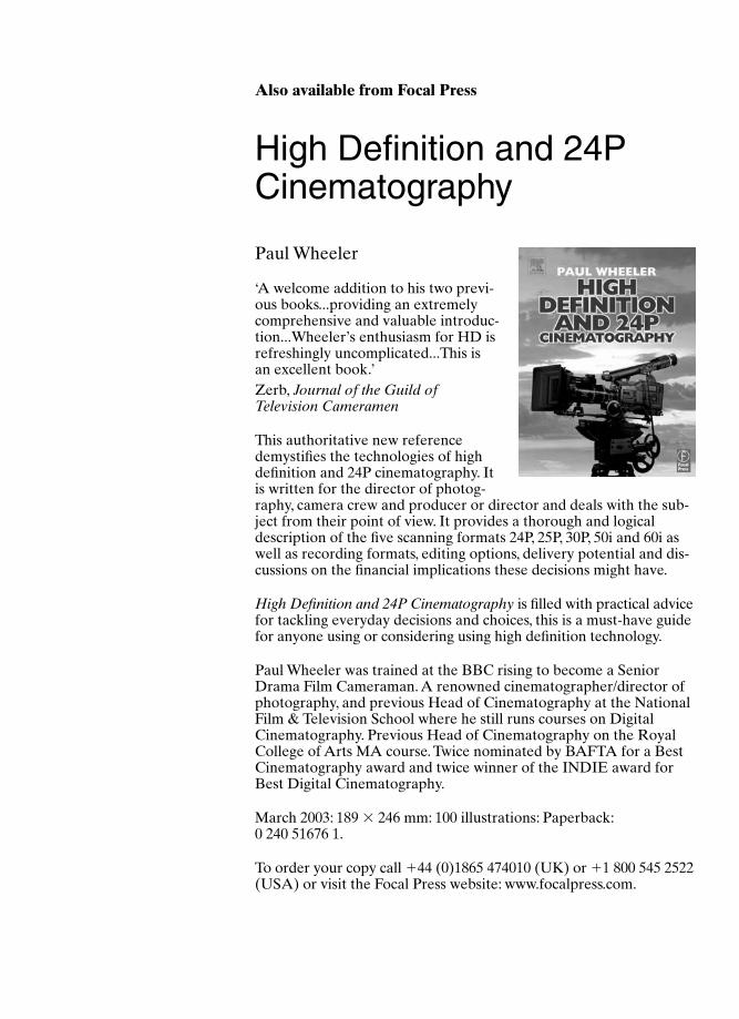
Also available from Focal Press
High Definition and 24PCinematography
Paul Wheeler
‘A welcome addition to his two previ-ous books...providing an extremelycomprehensive and valuable introduc-tion...Wheeler’s enthusiasm for HD isrefreshingly uncomplicated...This isan excellent book.’Zerb, Journal of the Guild ofTelevision Cameramen
This authoritative new referencedemystifies the technologies of highdefinition and 24P cinematography. Itis written for the director of photog-raphy, camera crew and producer or director and deals with the sub-ject from their point of view. It provides a thorough and logicaldescription of the five scanning formats 24P, 25P, 30P, 50i and 60i aswell as recording formats, editing options, delivery potential and dis-cussions on the financial implications these decisions might have.
High Definition and 24P Cinematography is filled with practical advicefor tackling everyday decisions and choices, this is a must-have guidefor anyone using or considering using high definition technology.
Paul Wheeler was trained at the BBC rising to become a SeniorDrama Film Cameraman. A renowned cinematographer/director ofphotography, and previous Head of Cinematography at the NationalFilm & Television School where he still runs courses on DigitalCinematography. Previous Head of Cinematography on the RoyalCollege of Arts MA course. Twice nominated by BAFTA for a BestCinematography award and twice winner of the INDIE award forBest Digital Cinematography.
March 2003: 189 � 246 mm: 100 illustrations: Paperback:0 240 51676 1.
To order your copy call �44 (0)1865 474010 (UK) or �1 800 545 2522(USA) or visit the Focal Press website: www.focalpress.com.
Advt 12/16/04 2:59 PM Page 206
Also available from Focal Press
Cinematography
Image Making forCinematographers,Directors and VideographersBlain Brown
‘A gorgeous piece of work thatbids to become a classic text oncinematography … . Few books oncinematography meld aestheticsand pragmatics as deftly as thisone.’American Cinematographer
• The definitive guide to cinematography
● Up-to-date coverage of technical topics, including HighDefinition and digital imaging
• Beautifully illustrated throughout to bring issues of color and lightto life
Lavishly produced and illustrated, Cinematography covers the entirerange of the profession. The book is not just a comprehensive guideto current professional practice; it goes beyond to explain the theorybehind the practice, so you understand how the rules came about and when it’s appropriate to break them. In addition, directors willbenefit from the book’s focus on the body of knowledge they shouldshare with their Director of Photography.
Blain Brown was educated at CW Post College; MIT and HarvardGraduate School of Design. He has completed projects as a director,editor and screenwriter; with three screenplays produced. He hasalso taught courses in storytelling and visual communication. As aDirector of Photography specializing in features and commercials, heis now based in Los Angeles. His books include A Sense of Place;Motion Picture and Video Lighting and The Filmmaker’s PocketReference. His work can be seen at www.BlainBrown.com.
October 2002: 189 � 246 mm: 450 colour illustrations: Paperback:0 240 80500 3.
To order your copy call �44 (0)1865 474010 (UK) or �1 800 545 2522(USA) or visit the Focal Press website: www.focalpress.com.
Advt 12/16/04 2:59 PM Page 207

Focal Press www.focalpress.com
Join Focal Press onlineAs a member you will enjoy the following benefits:
● browse our full list of books available● view sample chapters● order securely online
Focal eNewsRegister for eNews, the regular email service from Focal Press,to receive:
● advance news of our latest publications● exclusive articles written by our authors● related event information● free sample chapters● information about special offers
Go to www.focalpress.com to register and the eNews bulletin will soon be arriving on your desktop!
If you require any further information about the eNews or www.focalpress.com please contact:
USA Europe and rest of worldTricia Geswell Lucy Lomas-WalkerEmail: [email protected] Email: [email protected]: �1 781 313 4739 Tel: �44 (0) 1865 314438
CatalogueFor information on all Focal Press titles, our full catalogue is available online at www.focalpress.com, alternatively you can contact us for a free printed version:
USA Europe and rest of worldEmail: [email protected] Email: [email protected]: �1 781 313 4721 Tel: �44 (0) 1865 314220
Potential authorsIf you have an idea for a book, please get in touch:
USA Europe and rest of [email protected] [email protected]
Advt 12/16/04 2:59 PM Page 208