practica 1-conocer edlab
TRANSCRIPT

8/2/2019 Practica 1-Conocer EdLab
http://slidepdf.com/reader/full/practica-1-conocer-edlab 1/10
°o
....$.
SERIES CIRCUIT & OH:VIS L-\W
Obj t'ct ive:
This first experiment introduces the operation and use of the E
tr3.iner fo r studies in Electricity an d Electronics C ircuits. YrJU \vi l l ' \v i re"
Circuit :lnd use OH:\I'S L-\\\' to relate VOLTAGE, RESlST.-\.:-·¡CE and C C R R E ~ T . You wi11 3.lso use resistors in SERIES. The Experiment ~ l a n u a l c:ontains an
Objecti\'e, a Description of the circuits and Experimental Procedures. ThE:
Procedure describes ho\\" th e experiment is wired on the equipment, how méasure-
ments :lre L1Ken and where the results are recorded and reviewed. A series of
c:.llcubtions ° comparisons, and questions are then presented.
De::3cription:
ED- L\B T n iner .
T he ED- L-\B T r:lÍner should be placed on atable with th e pov,;er co rd (;fJn-
112cred to stJ.nd:Hd 11.) \'olt A. e, power outlet. The connection or "patching
; jJ. lun: l c:1:)les' ~ l l ' e the only other requirement in addirion to this manual. A pencil:l.nd pJ.per :1l't2 used for recording th e results of the experiments . Other special
:t¿.¡:,s such :1S \'J.cuum Tunes, Integrated Circuits , Transformers, and Printed
Circuits J.re used in b ter experiments . . \ sketch of a typical arrangement issho\xn bdo\\":
E ~ e c t r i c : l 1 Outlet --,
t(1) Tr3.iner I
(.!) PapE:r and Pencil -,
I
- - --
---- -
ro \.
0\.
..
(2 ) P:.ltch Cúrds-
_lJ.g1.1 l' é 1 - 1 L.-\B LA YOl'T D. C. CTHC UTS

8/2/2019 Practica 1-Conocer EdLab
http://slidepdf.com/reader/full/practica-1-conocer-edlab 2/10
.,
UNIT NO.',:;. , ,) .
Ed-lab
Electrical Components
SERIES CIRCUITS & OHMS LAWEXP. NO.
Poge No.
All components are permanently mounted on the unit inc:luding Power
Supplies, Meter, Electrical Parts, Signal Generator, and Switches. The experiments in this first unit on D. C. circuits require no other test equipment. Later
experiments will require the use and study of the Oscilloscope, Multimeter, and
Sinewave Generator.
The Power Supplies have "current limiting" to protect the components
against "burning-out" due to incorrect wiring. The student is thus advised not
to hesitate in connecting any circuits or in experimenting in any way with the
equipment.
DO NOT CONNECT ANY EXTERNAL POWER SUPPLY TO THIS UNIT.
The parts are mounted directly beneath the electrical schematic symbol
on thp. panel as shown below:
CONNECTION BANANA PLUG
PANEL
RESISTOR
TRANSISTOR
Figure 1- 2 Component Panel - Cut-Away \lie\\'
1
2
. .
!I¡1I
I
1-

8/2/2019 Practica 1-Conocer EdLab
http://slidepdf.com/reader/full/practica-1-conocer-edlab 3/10
- - - - - - - - - - - - - - - - - - - - - - - - - - - - - - - - - - - - - - - - ~ - - - - - - - - - - - - - - ~ - - - - - - - - - - ~
Ed-Lab SERIES CIRCUIT & OHMS LAW
E D- LAB Panel
UNIT NO. 1
EXP. NO.
Poge No.
1
3
A sketch reviewing all oí the component parts on the Ed-Lab is shownbelow:
Negative Power Supplies Positive Power Supplies
PowerTransformer
Power "ON"
S\vitch
SpecialSem iconductors
' Series Circuit
Ground
Diodes Resistors
Transistors
Tie Points
Signal Generator
Figure 1- 3 Ed-Lab 650 Components
/ '
, /
R. F. Coi!,Trans-former
Inductors
Capacitors
A simple series resistor circuit consists of a voltage source and a
resistor as shown below. The current corresponds to the rate oí flow of electrons.
"E"
VOLTAGE
(i n VOLTS)
+
CURRENT IvIETER
CONVENTIONAL
CURRENT
e e "1"..
ELECTH0Ñ\CUHHENT e
CUHHENT (in AMPERES)
Figure 1 -4 Simple Series Cil'cuit
'1\ "RESISTANCE
( in OHMSI

8/2/2019 Practica 1-Conocer EdLab
http://slidepdf.com/reader/full/practica-1-conocer-edlab 4/10
! .
UNIT NO. 1 ' . ;
:d-Lab SERIES CIRCUIT & OHMS LAWEXP. NO. _ 1
Poge No.
The relationship between VOLTAGE, CURRENT, and RESISTANCE is
given by OHM'S LAW and is:
where
Procedure:
1 = ER
E is the voltage in VOLTS.IR is the resistance in OHMS.
1 is the current in AMPERES.
1. The series circuit is shown below. The meter consists oí acoil
near a magneto When current flows in the coil, a force results in
a movement or deflection of the needle or pointer. The amount oí
current is then read on the meter scale.
+V2 +50Jl.a -wire 1J T T Lwire 2
I+
VOLTAGE R 470K
SOURCE - METER
-.--
-
GROUND~ W i r e 3
~ ~ L - . -=- WIRING SCHEMATIC
Figure 1- 5 EXPERIMENT - Series Circuit
........, , - - - - - - - - - - - - - - - - - - - - - - - - - - - - - - - -
,,,
1

8/2/2019 Practica 1-Conocer EdLab
http://slidepdf.com/reader/full/practica-1-conocer-edlab 5/10
. ,.) l. .
• 1, -
UNIT NO. 1
Ed-Lab SERIES CIRCUIT & OHMS LAWEXP. NO.
Poge' No.
The a ~ t u a l wiring is as shown below. Three wires (o r "leads!! or
Tlpatch cords ") are used to wire the circuito All future experimentswill not show this PICTORIAL WIRING but will only show the SCHEMATIC
DIAGRAM similar to that given on the previous page.
wire 3 1
GROUND
VARIABLE FL'\ED- I ~ ~ + V ~ O +NV
.V l
wire 1 ·
o
METEH
Figure 1- G Wiring Pictorial - Series Circuit.
- ',. ,
1
5
________- - - - - - - - - - .1
.
"<:"l<!.1.

8/2/2019 Practica 1-Conocer EdLab
http://slidepdf.com/reader/full/practica-1-conocer-edlab 6/10
SERIES CIRCUIT & OHMS LAW
UNIT NO. 1
EXP. NO.
Page No.
2. A current of +50,.ua (MICROAMPERES) wil! cause a ful! scale
reading of the meter. A MICROAMPERE is one millionth of an
ampere or 10-6 amperes.
The "K" on the Resistance Value indicates "KILOHMS" or 1,000
OHMS or 103 OHMS. Th e resistance used in the circuit is
therefore:
470K = 470,000 OHMS = 470 103
OHMS
3. Wire the series circuit given in Figure 1- 5.
Read the current on the meter and enter the data in the table below:
Use the scale marked O, 10, 20, 30, 40, and 50. Each division
on the scale corresponds to 1 microampere.
Enter the data below. You should be able to read to within 1/2
(or .5) space. Typical readings should then be 20. O, 19.5, 20.5, etc .
.1 CURRENT = _____ MICROAMPERES
4. Calculate the Voltage using OHMS LAW.
E= VOLTS
ENTER CALCULATION HERE.
(SHOULD BE APPROXIMATELY 9 VOLTS)
Many exercises are given in the next experiment for Kilohms,
Megohms, Ohms, Amperes, Milliamperes, Microamperes, VoJts,
Millivolts, Microvolts.
5. Series Resistors.
When Resistors are connected in "SERIES", the total resistance
(R T) is equal to the sum of the resistances.
Thus, for:
100K 470K
- -
the total resistance is 570 K.
1
6

8/2/2019 Practica 1-Conocer EdLab
http://slidepdf.com/reader/full/practica-1-conocer-edlab 7/10
' ; : , . - - c.4 - - -
Ed-Lab SERIES CIRCUIT & OHMS LAW
UNIT NO. 1
EXP. NO.
Page No.
The series resistance circuit schematic is thus:
+V2
+
-ro--
GROUND
+ 0}' a r - - - - - - .....
100K 470K
RT
= lOOK + 470K
RT
= 570K
Figure 1- 7 EXPERIMENT - Series Resistance Circuit
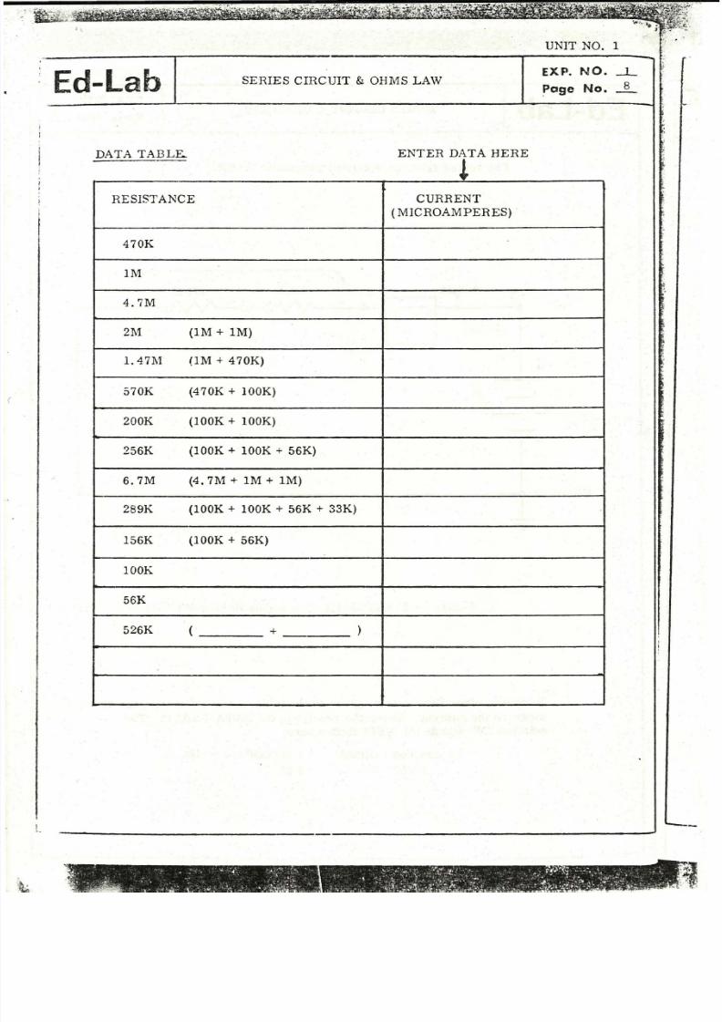
Substitute other Resistors as given in tb e tabIe on the following page and
measure the current. Enter th e results in the DATA T AB LE. The
notation !1M" stands fo r MEGOHMS where:
1,000,000 OHMS
1,000 K
- 1 MEGOHM = 1M
= 1 M
1
7
l---------------------------r
8/2/2019 Practica 1-Conocer EdLab
http://slidepdf.com/reader/full/practica-1-conocer-edlab 8/10
Ed-Lab SERIES CIHCUIT & OHMS LAW
DATA TABLE.. ENTER DATA HERE
!RESISTANCE CURRENT
( MICROAMPERES)
470K
1M
4.7M
2M (1M + 1M)
1. 47T\1 (lM + 470K)
570K (470K + 100K)
200K (100K + 100K)
256K (100K + 100K + 56K)
6.7M (4. 7M + 1M + 1M)
289K (100K + 100K + 56K + 33K)
156K (100K + 56K)
lOOK
56K
526K ( + )
UNIT NO. 1
EXP. NO. -LPoge No. _8_
.• '1, '

8/2/2019 Practica 1-Conocer EdLab
http://slidepdf.com/reader/full/practica-1-conocer-edlab 9/10
.
_.,
. . " 23
UNIT NO . 1
Ed-Lab SERIES CIRCUIT & OHMS LAWEXP. NO.
Poge No.
Two problems occur when reading current with the microammeter.
1. When R = lOOK is used, the current is too high and the meter
needle reads "above scale".
2. When R = 6. 7M is used, the current is too low and it is difficultto accurately read the current on the scale. The meter has a "SENSITIVITY"
of 50 microamperes fo r full scale.
It is necessary to use a high current meter with a "SHUNT" as in
Experiment No. 9 to read high currents. I t is necessary to use a "SENSITIVE
METER ClRCUIT" using a transistor amplifier as in Unit No. 2, Experiment
No. 14 to read the low microampere current.
6. Calculate the VOLTAGE (+V2) using OHMS LAW for various readings.
, Use the data from the Table on Page 8.
RESISTANCE CURRENT
(data from Table on Page 8)
470K
.lM
2M
570K
200K
100K
4.7M
6.7M
VOLTAGE (E)
(calculate E = 1 • R)
;,:Jt:J.

8/2/2019 Practica 1-Conocer EdLab
http://slidepdf.com/reader/full/practica-1-conocer-edlab 10/10
UNIT NO. 1,., . - - - - - - ~ - - - - - -
SEHIES CIRCUIT & OHM' S LAWn:p. NO.
PClgc No.
Plot Voltage versus Re sistance from f:1e previous table
1(1
8VOLTAGE
E(:
4 -
o t ilOOK 300K 500K 800K 1M 2M 3M 4M 5M 6M 7M
RESISTANCE R
V se a ruler to draw a straight line through the points. Observe Lhat th e voltage
remains constant . The current varies as th e resistance is chang.::d. Any
differences in current are due to errors in meter reading or "tolE:::"ance errors"
i: l resí stor values. l f any of your readings are far "ofF the lir.e, r 2peat those
readings.
Questio'1S:
1. When a large resistor is in series with a small resisto!', is the
resultant resistor large or small1.
2. Ca1culate th e current for E = 5 VOLTS, and R = 22K.
3 .Ca l cu l a t e th e current fo r E = 8.5 volts and two series res i stors
R 1 = 56K and R 2 = 22K.
4. I f you have a MULTIMETER available, use the OHT\lS scale a.nd
measure the resistance of each of th e resistors. List the standard
value given and the measured values in a data tableo
1
10