ppe assignment
DESCRIPTION
Process plant eng assignmentTRANSCRIPT

PROCESS PLANT
ENGINEERING
ASSIGNMENT 2 Name : Libbis Sujessy Student ID : (7E3B2332/17484688)
Process plant engineering | Libbis Sujessy/7E3B2332/17484688
1
Question 1
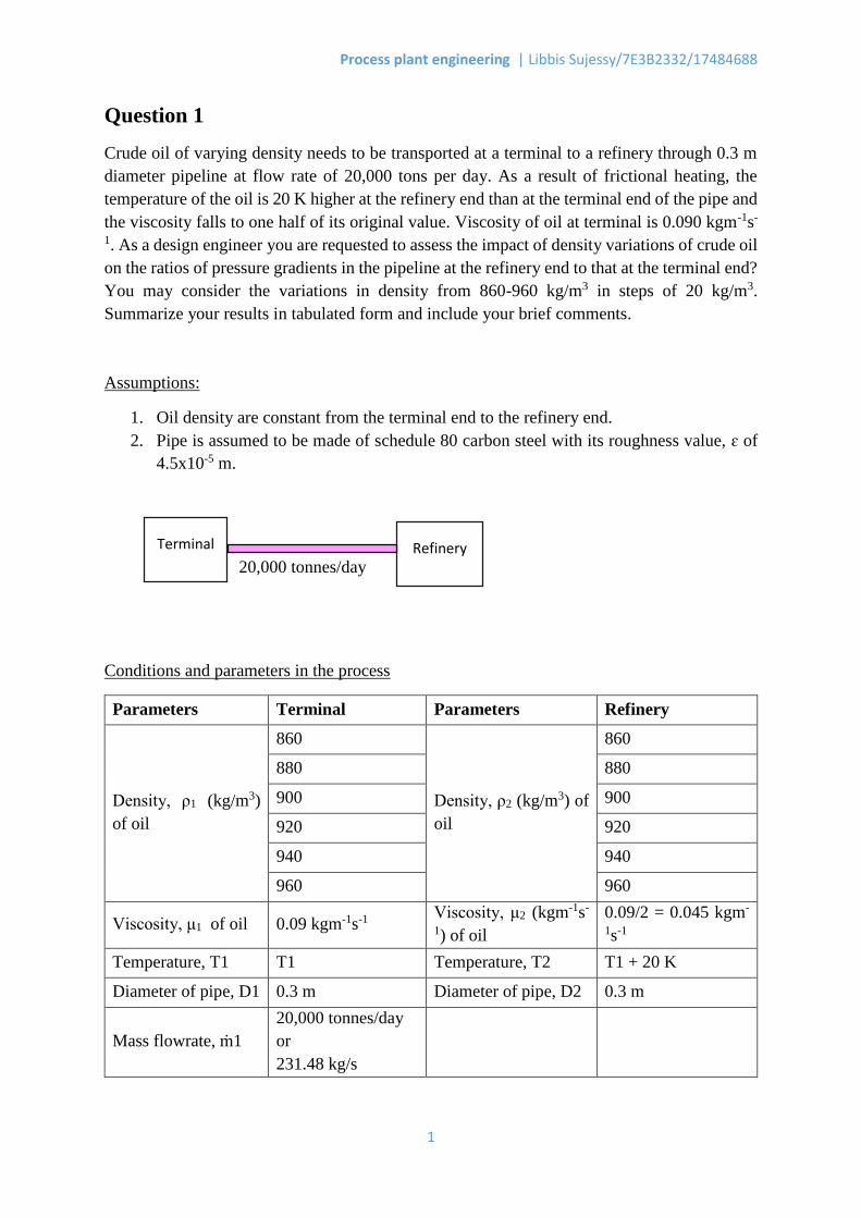
Crude oil of varying density needs to be transported at a terminal to a refinery through 0.3 m
diameter pipeline at flow rate of 20,000 tons per day. As a result of frictional heating, the
temperature of the oil is 20 K higher at the refinery end than at the terminal end of the pipe and
the viscosity falls to one half of its original value. Viscosity of oil at terminal is 0.090 kgm-1s-
1. As a design engineer you are requested to assess the impact of density variations of crude oil
on the ratios of pressure gradients in the pipeline at the refinery end to that at the terminal end?
You may consider the variations in density from 860-960 kg/m3 in steps of 20 kg/m3.
Summarize your results in tabulated form and include your brief comments.
Assumptions:
1. Oil density are constant from the terminal end to the refinery end.
2. Pipe is assumed to be made of schedule 80 carbon steel with its roughness value, ɛ of
4.5x10⁻⁵ m.
20,000 tonnes/day
Conditions and parameters in the process
Parameters Terminal Parameters Refinery
Density, ρ1 (kg/m3)
of oil
860
Density, ρ2 (kg/m3) of
oil
860
880 880
900 900
920 920
940 940
960 960
Viscosity, μ1 of oil 0.09 kgm-1s-1 Viscosity, μ2 (kgm-1s-
1) of oil
0.09/2 = 0.045 kgm-
1s-1
Temperature, T1 T1 Temperature, T2 T1 + 20 K
Diameter of pipe, D1 0.3 m Diameter of pipe, D2 0.3 m
Mass flowrate, ṁ1
20,000 tonnes/day
or
231.48 kg/s
Terminal Refinery
Process plant engineering | Libbis Sujessy/7E3B2332/17484688
2
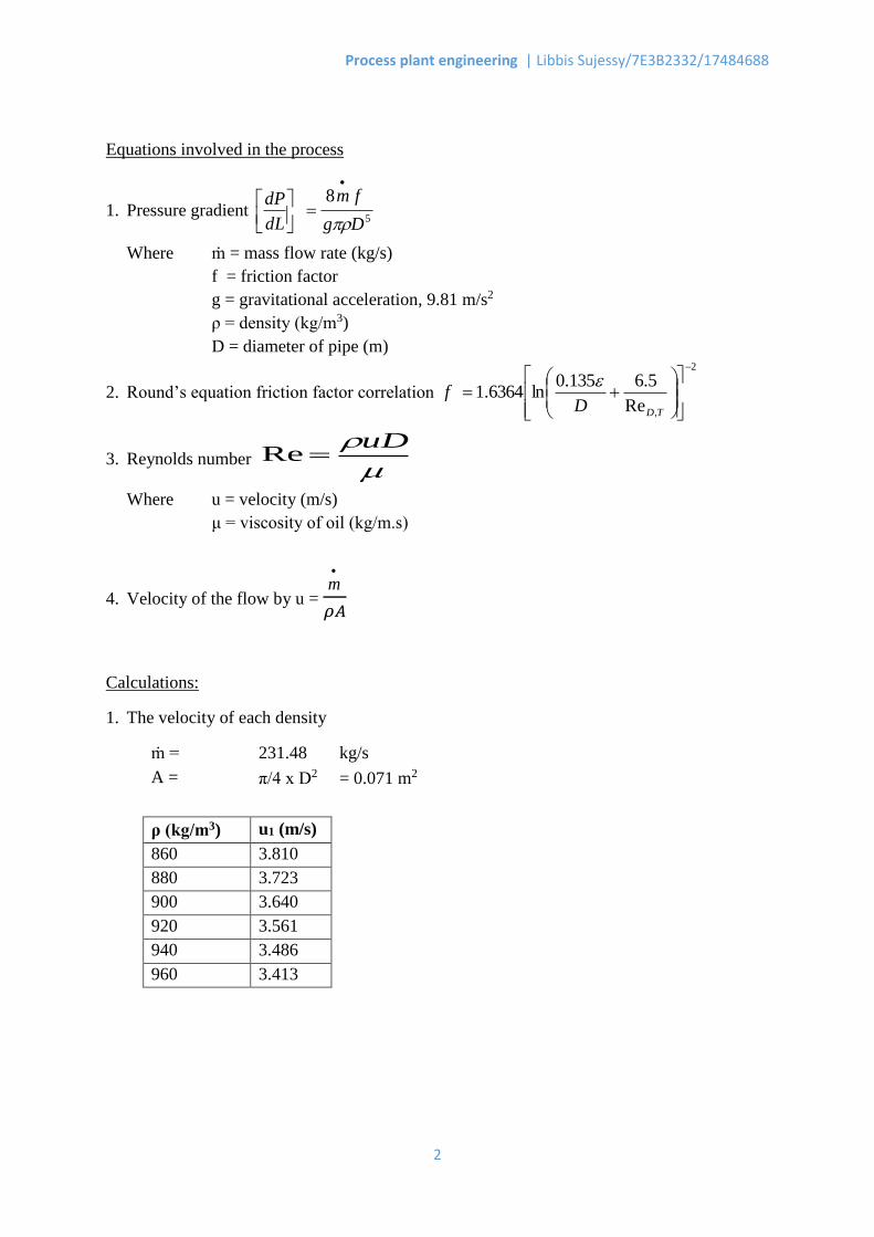
Equations involved in the process
1. Pressure gradient 5
8
Dg
fm
dL
dP
Where ṁ = mass flow rate (kg/s)
f = friction factor
g = gravitational acceleration, 9.81 m/s2
ρ = density (kg/m3)
D = diameter of pipe (m)
2. Round’s equation friction factor correlation
2
,Re
5.6135.0ln6364.1
TDDf
3. Reynolds number
uDRe
Where u = velocity (m/s)
μ = viscosity of oil (kg/m.s)
4. Velocity of the flow by u =
m
𝜌𝐴
Calculations:
1. The velocity of each density
ṁ = 231.48 kg/s
A = π/4 x D2 = 0.071 m2
ρ (kg/m3) u1 (m/s)
860 3.810
880 3.723
900 3.640
920 3.561
940 3.486
960 3.413
Process plant engineering | Libbis Sujessy/7E3B2332/17484688
3
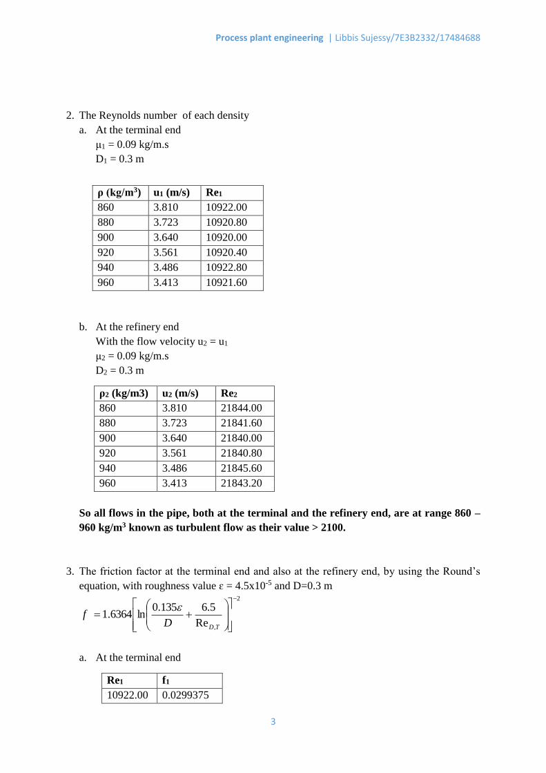
2. The Reynolds number of each density
a. At the terminal end
μ1 = 0.09 kg/m.s
D1 = 0.3 m
b. At the refinery end
With the flow velocity u2 = u1
μ2 = 0.09 kg/m.s
D2 = 0.3 m
ρ2 (kg/m3) u2 (m/s) Re2
860 3.810 21844.00
880 3.723 21841.60
900 3.640 21840.00
920 3.561 21840.80
940 3.486 21845.60
960 3.413 21843.20
So all flows in the pipe, both at the terminal and the refinery end, are at range 860 –
960 kg/m3 known as turbulent flow as their value > 2100.
3. The friction factor at the terminal end and also at the refinery end, by using the Round’s
equation, with roughness value ɛ = 4.5x10⁻⁵ and D=0.3 m 2
,Re
5.6135.0ln6364.1
TDDf
a. At the terminal end
Re1 f1
10922.00 0.0299375
ρ (kg/m3) u1 (m/s) Re1
860 3.810 10922.00
880 3.723 10920.80
900 3.640 10920.00
920 3.561 10920.40
940 3.486 10922.80
960 3.413 10921.60
Process plant engineering | Libbis Sujessy/7E3B2332/17484688
4
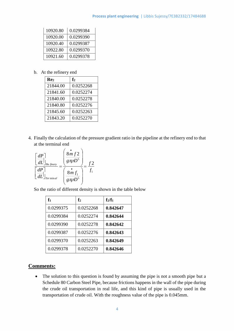
10920.80 0.0299384
10920.00 0.0299390
10920.40 0.0299387
10922.80 0.0299370
10921.60 0.0299378
b. At the refinery end
4. Finally the calculation of the pressure gradient ratio in the pipeline at the refinery end to that
at the terminal end
1
5
1
5
min
Re 2
8
28
f
f
Dg
fm
Dg
fm
dL
dP
dL
dP
alTer
finery
So the ratio of different density is shown in the table below
f1 f2 f2/f1
0.0299375 0.0252268 0.842647
0.0299384 0.0252274 0.842644
0.0299390 0.0252278 0.842642
0.0299387 0.0252276 0.842643
0.0299370 0.0252263 0.842649
0.0299378 0.0252270 0.842646
Comments:
The solution to this question is found by assuming the pipe is not a smooth pipe but a
Schedule 80 Carbon Steel Pipe, because frictions happens in the wall of the pipe during
the crude oil transportation in real life, and this kind of pipe is usually used in the
transportation of crude oil. With the roughness value of the pipe is 0.045mm.
Re2 f2
21844.00 0.0252268
21841.60 0.0252274
21840.00 0.0252278
21840.80 0.0252276
21845.60 0.0252263
21843.20 0.0252270
Process plant engineering | Libbis Sujessy/7E3B2332/17484688
5
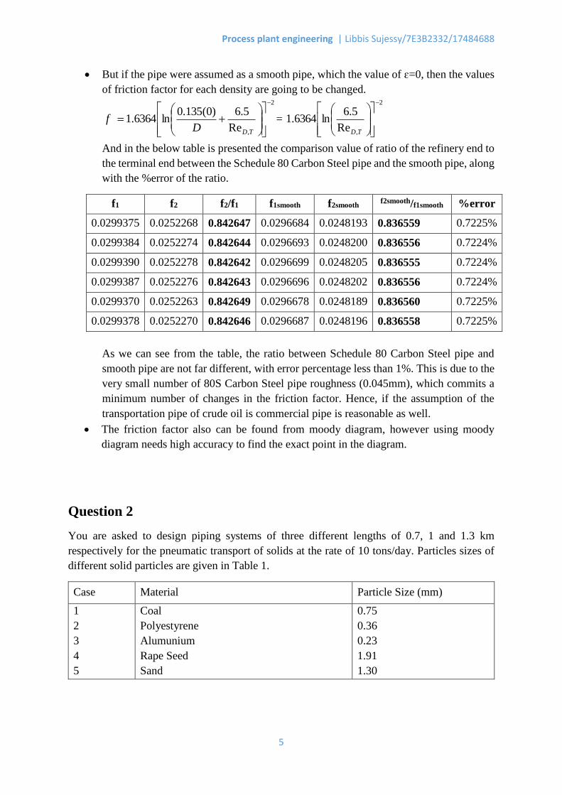
But if the pipe were assumed as a smooth pipe, which the value of ɛ=0, then the values
of friction factor for each density are going to be changed. 2
,Re
5.6)0(135.0ln6364.1
TDDf =
2
,Re
5.6ln6364.1
TD
And in the below table is presented the comparison value of ratio of the refinery end to
the terminal end between the Schedule 80 Carbon Steel pipe and the smooth pipe, along
with the %error of the ratio.
f1 f2 f2/f1 f1smooth f2smooth f2smooth/f1smooth %error
0.0299375 0.0252268 0.842647 0.0296684 0.0248193 0.836559 0.7225%
0.0299384 0.0252274 0.842644 0.0296693 0.0248200 0.836556 0.7224%
0.0299390 0.0252278 0.842642 0.0296699 0.0248205 0.836555 0.7224%
0.0299387 0.0252276 0.842643 0.0296696 0.0248202 0.836556 0.7224%
0.0299370 0.0252263 0.842649 0.0296678 0.0248189 0.836560 0.7225%
0.0299378 0.0252270 0.842646 0.0296687 0.0248196 0.836558 0.7225%
As we can see from the table, the ratio between Schedule 80 Carbon Steel pipe and
smooth pipe are not far different, with error percentage less than 1%. This is due to the
very small number of 80S Carbon Steel pipe roughness (0.045mm), which commits a
minimum number of changes in the friction factor. Hence, if the assumption of the
transportation pipe of crude oil is commercial pipe is reasonable as well.
The friction factor also can be found from moody diagram, however using moody
diagram needs high accuracy to find the exact point in the diagram.
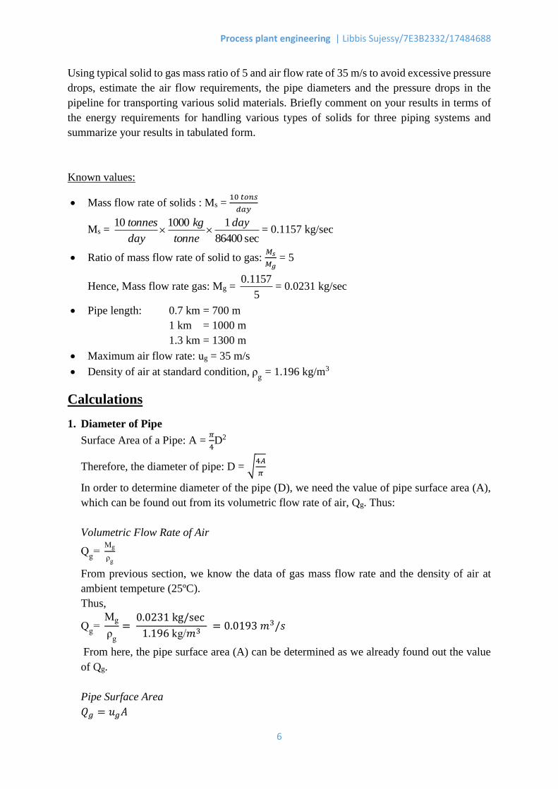
Question 2
You are asked to design piping systems of three different lengths of 0.7, 1 and 1.3 km
respectively for the pneumatic transport of solids at the rate of 10 tons/day. Particles sizes of
different solid particles are given in Table 1.
Case Material Particle Size (mm)
1
2
3
4
5
Coal
Polyestyrene
Alumunium
Rape Seed
Sand
0.75
0.36
0.23
1.91
1.30
Process plant engineering | Libbis Sujessy/7E3B2332/17484688
6
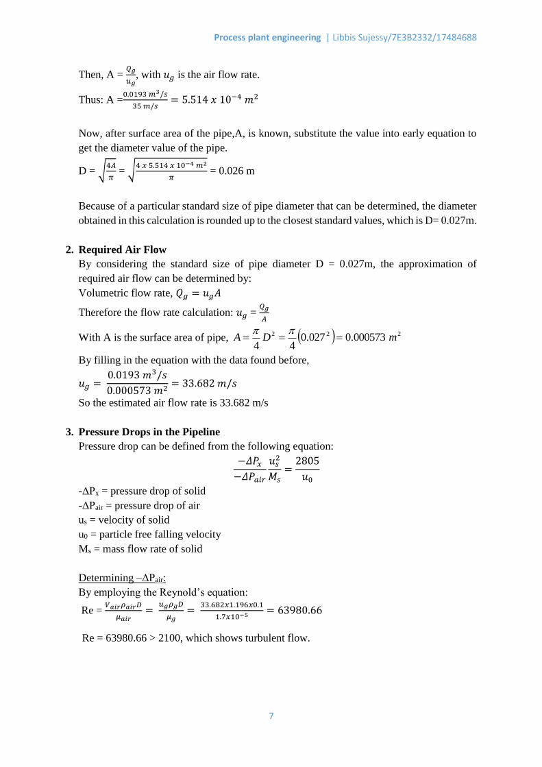
Using typical solid to gas mass ratio of 5 and air flow rate of 35 m/s to avoid excessive pressure
drops, estimate the air flow requirements, the pipe diameters and the pressure drops in the
pipeline for transporting various solid materials. Briefly comment on your results in terms of
the energy requirements for handling various types of solids for three piping systems and
summarize your results in tabulated form.
Known values:
Mass flow rate of solids : Ms = 10 𝑡𝑜𝑛𝑠
𝑑𝑎𝑦
Ms = sec86400
1100010 day
tonne
kg
day
tonnes = 0.1157 kg/sec
Ratio of mass flow rate of solid to gas: 𝑀𝑠
𝑀𝑔 = 5
Hence, Mass flow rate gas: Mg = 5
1157.0= 0.0231 kg/sec
Pipe length: 0.7 km = 700 m
1 km = 1000 m
1.3 km = 1300 m
Maximum air flow rate: ug = 35 m/s
Density of air at standard condition, ρg = 1.196 kg/m3
Calculations
1. Diameter of Pipe
Surface Area of a Pipe: A = 𝜋
4D2
Therefore, the diameter of pipe: D = √4𝐴
𝜋
In order to determine diameter of the pipe (D), we need the value of pipe surface area (A),
which can be found out from its volumetric flow rate of air, Qg. Thus:
Volumetric Flow Rate of Air
Qg=
Mg
ρg
From previous section, we know the data of gas mass flow rate and the density of air at
ambient tempeture (25ºC).
Thus,
Qg=
Mg
ρg
= 0.0231 kg/sec
1.196 kg/𝑚3 = 0.0193 𝑚3/𝑠
From here, the pipe surface area (A) can be determined as we already found out the value
of Qg.
Pipe Surface Area
𝑄𝑔 = 𝑢𝑔𝐴
Process plant engineering | Libbis Sujessy/7E3B2332/17484688
7
Then, A = 𝑄𝑔
𝑢𝑔, with 𝑢𝑔 is the air flow rate.
Thus: A =0.0193 𝑚3/𝑠
35 𝑚/𝑠= 5.514 𝑥 10−4 𝑚2
Now, after surface area of the pipe,A, is known, substitute the value into early equation to
get the diameter value of the pipe.
D = √4𝐴
𝜋 = √
4 𝑥 5.514 𝑥 10−4 𝑚2
𝜋 = 0.026 m
Because of a particular standard size of pipe diameter that can be determined, the diameter
obtained in this calculation is rounded up to the closest standard values, which is D= 0.027m.
2. Required Air Flow
By considering the standard size of pipe diameter D = 0.027m, the approximation of
required air flow can be determined by:
Volumetric flow rate, 𝑄𝑔 = 𝑢𝑔𝐴
Therefore the flow rate calculation: 𝑢𝑔 = 𝑄𝑔
𝐴
With A is the surface area of pipe, 222 000573.0027.044
mDA
By filling in the equation with the data found before,
𝑢𝑔 = 0.0193 𝑚3/𝑠
0.000573 𝑚2= 33.682 𝑚/𝑠
So the estimated air flow rate is 33.682 m/s
3. Pressure Drops in the Pipeline
Pressure drop can be defined from the following equation:
−𝛥𝑃𝑥
−𝛥𝑃𝑎𝑖𝑟
𝑢𝑠2
𝑀𝑠=
2805
𝑢0
-ΔPx = pressure drop of solid
-ΔPair = pressure drop of air
us = velocity of solid
u0 = particle free falling velocity
Ms = mass flow rate of solid
Determining –ΔPair:
By employing the Reynold’s equation:
Re = 𝑉𝑎𝑖𝑟𝜌𝑎𝑖𝑟𝐷
𝜇𝑎𝑖𝑟=
𝑢𝑔𝜌𝑔𝐷
𝜇𝑔=
33.682𝑥1.196𝑥0.1
1.7𝑥10−5 = 63980.66
Re = 63980.66 > 2100, which shows turbulent flow.
Process plant engineering | Libbis Sujessy/7E3B2332/17484688
8
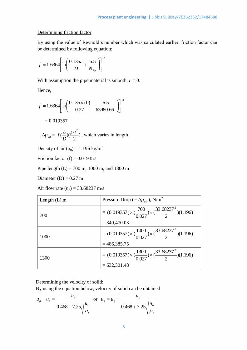
Determining friction factor
By using the value of Reynold’s number which was calculated earlier, friction factor can
be determined by following equation:
2
Re
5.6135.0ln6364.1
NDf
With assumption the pipe material is smooth, ɛ = 0.
Hence,
2
63980.66
5.6
27.0
)0(135.0ln6364.1
f
= 0.019357
airp = )2
)((2u
D
Lf
, which varies in length
Density of air (ρg) = 1.196 kg/m3
Friction factor (f) = 0.019357
Pipe length (L) = 700 m, 1000 m, and 1300 m
Diameter (D) = 0.27 m
Air flow rate (ug) = 33.68237 m/s
Length (L),m Pressure Drop ( airp ), N/m2
700 = )196.1)(
2
68237.33()
027.0
700()0.019357(
2
= 340,470.03
1000 = )196.1)(
2
68237.33()
027.0
1000()0.019357(
2
= 486,385.75
1300 = )196.1)(
2
68237.33()
027.0
1300()0.019357(
2
= 632,301.48
Determining the velocity of solid:
By using the equation below, velocity of solid can be obtained
s
o
osg
u
uuu
25.7468.0
or
s
o
ogs
u
uuu
25.7468.0
Process plant engineering | Libbis Sujessy/7E3B2332/17484688
9
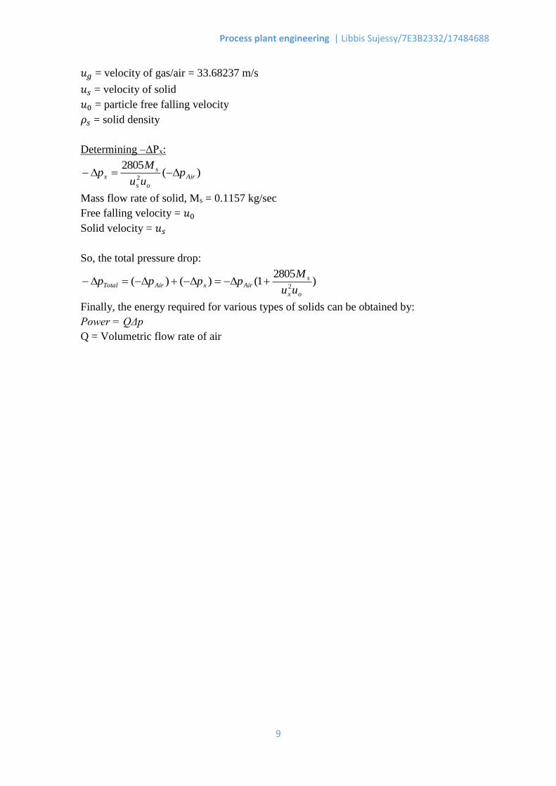
𝑢𝑔 = velocity of gas/air = 33.68237 m/s
𝑢𝑠 = velocity of solid
𝑢0 = particle free falling velocity
𝜌𝑠 = solid density
Determining –ΔPx:
)(2805
2 Air
os
sx p
uu
Mp
Mass flow rate of solid, Ms = 0.1157 kg/sec
Free falling velocity = 𝑢0
Solid velocity = 𝑢𝑠
So, the total pressure drop:
)2805
1()()(2
ox
sAirxAirTotal
uu
Mpppp
Finally, the energy required for various types of solids can be obtained by:
Power = QΔp
Q = Volumetric flow rate of air
Process plant engineering | Libbis Sujessy/7E3B2332/17484688
10
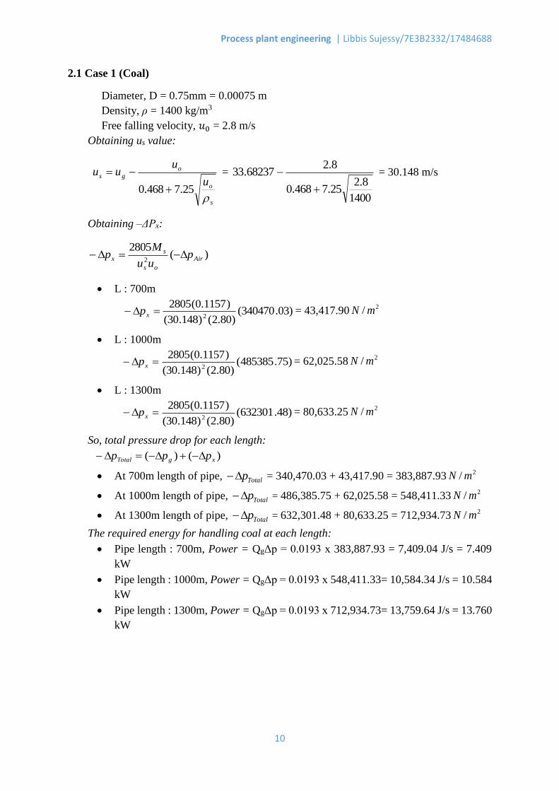
2.1 Case 1 (Coal)
Diameter, D = 0.75mm = 0.00075 m
Density, ρ = 1400 kg/m3
Free falling velocity, 𝑢0 = 2.8 m/s
Obtaining us value:
s
o
ogs
u
uuu
25.7468.0
=
1400
8.225.7468.0
8.268237.33
= 30.148 m/s
Obtaining –ΔPx:
)(2805
2 Air
os
sx p
uu
Mp
L : 700m
)03.340470()80.2()148.30(
)1157.0(28052
xp = 43,417.902/ mN
L : 1000m
)75.485385()80.2()148.30(
)1157.0(28052
xp = 62,025.582/ mN
L : 1300m
)48.632301()80.2()148.30(
)1157.0(28052
xp = 80,633.252/ mN
So, total pressure drop for each length:
)()( xgTotal ppp
At 700m length of pipe, Totalp = 340,470.03 + 43,417.90 = 383,887.932/ mN
At 1000m length of pipe, Totalp = 486,385.75 + 62,025.58 = 548,411.332/ mN
At 1300m length of pipe, Totalp = 632,301.48 + 80,633.25 = 712,934.732/ mN
The required energy for handling coal at each length:
Pipe length : 700m, Power = QgΔp = 0.0193 x 383,887.93 = 7,409.04 J/s = 7.409
kW
Pipe length : 1000m, Power = QgΔp = 0.0193 x 548,411.33= 10,584.34 J/s = 10.584
kW
Pipe length : 1300m, Power = QgΔp = 0.0193 x 712,934.73= 13,759.64 J/s = 13.760
kW
Process plant engineering | Libbis Sujessy/7E3B2332/17484688
11
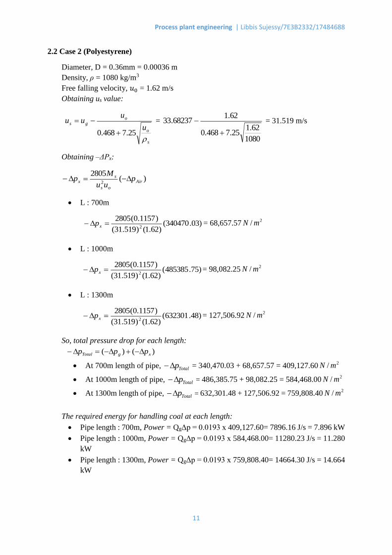
2.2 Case 2 (Polyestyrene)
Diameter, D = 0.36mm = 0.00036 m
Density, ρ = 1080 kg/m3
Free falling velocity, 𝑢0 = 1.62 m/s
Obtaining us value:
s
o
ogs
u
uuu
25.7468.0
=
1080
62.125.7468.0
62.168237.33
= 31.519 m/s
Obtaining –ΔPx:
)(2805
2 Air
os
sx p
uu
Mp
L : 700m
)03.340470()62.1()519.31(
)1157.0(28052
xp = 68,657.572/ mN
L : 1000m
)75.485385()62.1()519.31(
)1157.0(28052
xp = 98,082.252/ mN
L : 1300m
)48.632301()62.1()519.31(
)1157.0(28052
xp = 127,506.922/ mN
So, total pressure drop for each length:
)()( xgTotal ppp
At 700m length of pipe, Totalp = 340,470.03 + 68,657.57 = 409,127.602/ mN
At 1000m length of pipe, Totalp = 486,385.75 + 98,082.25 = 584,468.002/ mN
At 1300m length of pipe, Totalp = 632,301.48 + 127,506.92 = 759,808.402/ mN
The required energy for handling coal at each length:
Pipe length : 700m, Power = QgΔp = 0.0193 x 409,127.60= 7896.16 J/s = 7.896 kW
Pipe length : 1000m, Power = QgΔp = 0.0193 x 584,468.00= 11280.23 J/s = 11.280
kW
Pipe length : 1300m, Power = QgΔp = 0.0193 x 759,808.40= 14664.30 J/s = 14.664
kW
Process plant engineering | Libbis Sujessy/7E3B2332/17484688
12
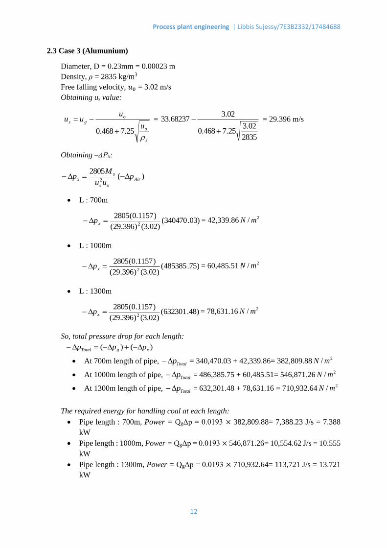
2.3 Case 3 (Alumunium)
Diameter, D = 0.23mm = 0.00023 m
Density, ρ = 2835 kg/m3
Free falling velocity, 𝑢0 = 3.02 m/s
Obtaining us value:
s
o
ogs
u
uuu
25.7468.0
=
2835
02.325.7468.0
02.368237.33
= 29.396 m/s
Obtaining –ΔPx:
)(2805
2 Air
os
sx p
uu
Mp
L : 700m
)03.340470()02.3()396.29(
)1157.0(28052
xp = 42,339.862/ mN
L : 1000m
)75.485385()02.3()396.29(
)1157.0(28052
xp = 60,485.512/ mN
L : 1300m
)48.632301()02.3()396.29(
)1157.0(28052
xp = 78,631.162/ mN
So, total pressure drop for each length:
)()( xgTotal ppp
At 700m length of pipe, Totalp = 340,470.03 + 42,339.86= 382,809.882/ mN
At 1000m length of pipe, Totalp = 486,385.75 + 60,485.51= 546,871.262/ mN
At 1300m length of pipe, Totalp = 632,301.48 + 78,631.16 = 710,932.642/ mN
The required energy for handling coal at each length:
Pipe length : 700m, Power = QgΔp = 0.0193 × 382,809.88= 7,388.23 J/s = 7.388
kW
Pipe length : 1000m, Power = QgΔp = 0.0193 × 546,871.26= 10,554.62 J/s = 10.555
kW
Pipe length : 1300m, Power = QgΔp = 0.0193 × 710,932.64= 113,721 J/s = 13.721
kW

Process plant engineering | Libbis Sujessy/7E3B2332/17484688
13
2.4 Case 4 (Rape Seed)
Diameter, D = 1.91mm = 0.00191 m
Density, ρ = 1080 kg/m3
Free falling velocity, 𝑢0 = 5.91 m/s
Obtaining us value:
s
o
ogs
u
uuu
25.7468.0
=
1080
91.525.7468.0
91.568237.33
= 27.798 m/s
Obtaining –ΔPx:
)(2805
2 Air
os
sx p
uu
Mp
L : 700m
)03.340470()91.5()798.27(
)1157.0(28052
xp = 24,195.692/ mN
L : 1000m
)75.485385()91.5()798.27(
)1157.0(28052
xp = 34,565.272/ mN
L : 1300m
)48.632301()91.5()798.27(
)1157.0(28052
xp = 44,934.852/ mN
So, total pressure drop for each length:
)()( xgTotal ppp
At 700m length of pipe, Totalp = 340,470.03 + 24,195.69 = 364,665.712/ mN
At 1000m length of pipe, Totalp = 486,385.75 + 34,565.27 = 520,951.022/ mN
At 1300m length of pipe, Totalp = 632,301.48 + 44,934.85 = 677,236.332/ mN
The required energy for handling coal at each length:
Pipe length : 700m, Power = QgΔp = 0.0193 × 364,665.71= 7038.05 J/s = 7.038 kW
Pipe length : 1000m, Power = QgΔp = 0.0193 × 520,951.02= 10,054.35 J/s = 10.054
kW
Pipe length : 1300m, Power = QgΔp = 0.0193 × 677,236.33= 13,070.66 J/s = 13.071
kW
Process plant engineering | Libbis Sujessy/7E3B2332/17484688
14
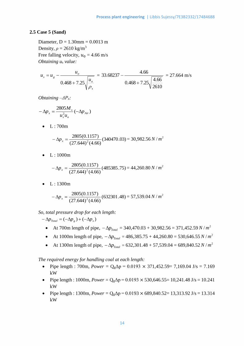
2.5 Case 5 (Sand)
Diameter, D = 1.30mm = 0.0013 m
Density, ρ = 2610 kg/m3
Free falling velocity, 𝑢0 = 4.66 m/s
Obtaining us value:
s
o
ogs
u
uuu
25.7468.0
=
2610
66.425.7468.0
66.468237.33
= 27.664 m/s
Obtaining –ΔPx:
)(2805
2 Air
os
sx p
uu
Mp
L : 700m
)03.340470()66.4()644.27(
)1157.0(28052
xp = 30,982.562/ mN
L : 1000m
)75.485385()66.4()644.27(
)1157.0(28052
xp = 44,260.802/ mN
L : 1300m
)48.632301()66.4()644.27(
)1157.0(28052
xp = 57,539.042/ mN
So, total pressure drop for each length:
)()( xgTotal ppp
At 700m length of pipe, Totalp = 340,470.03 + 30,982.56 = 371,452.592/ mN
At 1000m length of pipe, Totalp = 486,385.75 + 44,260.80 = 530,646.552/ mN
At 1300m length of pipe, Totalp = 632,301.48 + 57,539.04 = 689,840.522/ mN
The required energy for handling coal at each length:
Pipe length : 700m, Power = QgΔp = 0.0193 × 371,452.59= 7,169.04 J/s = 7.169
kW
Pipe length : 1000m, Power = QgΔp = 0.0193 × 530,646.55= 10,241.48 J/s = 10.241
kW
Pipe length : 1300m, Power = QgΔp = 0.0193 × 689,840.52= 13,313.92 J/s = 13.314
kW
Process plant engineering | Libbis Sujessy/7E3B2332/17484688
15
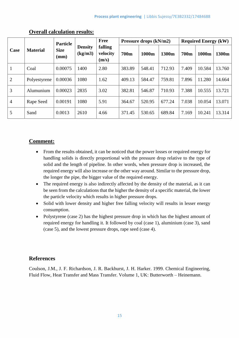
Overall calculation results:
Comment:
From the results obtained, it can be noticed that the power losses or required energy for
handling solids is directly proportional with the pressure drop relative to the type of
solid and the length of pipeline. In other words, when pressure drop is increased, the
required energy will also increase or the other way around. Similar to the pressure drop,
the longer the pipe, the bigger value of the required energy.
The required energy is also indirectly affected by the density of the material, as it can
be seen from the calculations that the higher the density of a specific material, the lower
the particle velocity which results in higher pressure drops.
Solid with lower density and higher free falling velocity will results in lesser energy
consumption.
Polystyrene (case 2) has the highest pressure drop in which has the highest amount of
required energy for handling it. It followed by coal (case 1), aluminium (case 3), sand
(case 5), and the lowest pressure drops, rape seed (case 4).
References
Coulson, J.M., J. F. Richardson, J. R. Backhurst, J. H. Harker. 1999. Chemical Engineering,
Fluid Flow, Heat Transfer and Mass Transfer. Volume 1, UK: Butterworth – Heinemann.
Case Material
Particle
Size
(mm)
Density
(kg/m3)
Free
falling
velocity
(m/s)
Pressure drops (kN/m2) Required Energy (kW)
700m 1000m 1300m 700m 1000m 1300m
1 Coal 0.00075 1400 2.80 383.89 548.41 712.93 7.409 10.584 13.760
2 Polyestyrene 0.00036 1080 1.62 409.13 584.47 759.81 7.896 11.280 14.664
3 Alumunium 0.00023 2835 3.02 382.81 546.87 710.93 7.388 10.555 13.721
4 Rape Seed 0.00191 1080 5.91 364.67 520.95 677.24 7.038 10.054 13.071
5 Sand 0.0013 2610 4.66 371.45 530.65 689.84 7.169 10.241 13.314