powerturn integrated closing mechanism -...
TRANSCRIPT

PowerturnIntegrated Closing Mechanism
EN Installation instructions
158635-00

Powerturn Integrated Closing Mechanism
2
Table of contents
1 Symbols and means of representation ............................................................................................................3
2 Product liability ........................................................................................................................................................3
3 Safety ...........................................................................................................................................................................33.1 Proper use ............................................................................................................................................................................................................33.2 Standards .............................................................................................................................................................................................................33.3 Reference documents .....................................................................................................................................................................................33.4 Safety instructions ............................................................................................................................................................................................3
4 Tools and aids ...........................................................................................................................................................4
5 Types of installation ................................................................................................................................................45.1 Type of installation transom installation hinge side ............................................................................................................................45.2 Type of installation transom installation opposite hinge side .........................................................................................................4
6 Product description ................................................................................................................................................56.1 Areas of application .........................................................................................................................................................................................56.2 Drive unit with pre-assembled integrated closing sequence control mechanism ...................................................................5
7 Installing the integrated closing sequence control mechanism ............................................................97.1 Installing the integrated closing mechanism of the active leaf drive ............................................................................................97.2 Installing the integrated closing mechanism of the fixed leaf drive ........................................................................................... 117.3 Connecting the integrated closing mechanism of active and fixed leaf ................................................................................... 13
8 Function check ...................................................................................................................................................... 17
9 Commissioning ..................................................................................................................................................... 17
10 Service and after-sales service maintenance ............................................................................................. 17
11 Troubleshooting .................................................................................................................................................. 17

Powerturn Integrated Closing Mechanism
3
Symbols and means of representation
1 Symbols and means of representationImportant information and technical notes are highlighted to explain correct operation.
Symbol Meaning
means "important note"
means "additional information"
X Symbol for an action: Here you have to do something.
X If there are several actions to be taken, keep to the given order.
2 Product liabilityIn accordance with the liability of the manufacturer for their products as defined in the German "Product Liability Act", the information contained in this brochure (product information and proper use, misuse, product perfor-mance, product maintenance, obligations to provide information and instructions) is to be observed. Failure to comply releases the manufacturer from their statutory liability.
3 Safety
3.1 Proper useThe Powerturn integrated closing sequence control has been designed for mechanical control during the closing of double-leaf single-action swing doors. The components required are a supplement to the Powerturn drive and must be installed according to these instructions.The Powerturn integrated closing sequence control à is designed for use on fire and smoke control doors. à may be used on emergency exits. à must not be used for potentially explosive areas.
Any other use than the proper use, such as permanent manual operation, as well as all changes to the product are impermissible.Observe the "GEZE Product information for door closers".
3.2 StandardsDuring installation of the closing sequence control, the applicable standards must be heeded corresponding to Powerdrive.DIN EN 1158 is also applicable
3.3 Reference documents à Powerturn installation instructions à Powerturn wiring diagram
The diagrams are subject to change without notice. Use only the most recent version.
3.4 Safety instructions
The description of the overall installation of the drive is not the subject of these instructions. This information can be found in the Powerturn installation instructions.All the necessary safety instructions for conversion or extension to a double-leaf version can be found on the fol-lowing pages.

Powerturn Integrated Closing Mechanism
4
Tools and aids
4 Tools and aidsTool Size
Drill bits Ø 2 mm
Open-ended spanner Size 5.5
Allen key 1.5 mm
Allen key 2.5 mm
Pozidrive screwdriver
5 Types of installation
5.1 Type of installation transom installation hinge sideWith this type of installation, only roller guide rail and lever can be used. Details about permissible reveal depth, door overlap and installation holes can be found in the Powerturn installation instructions.
Stand�ügel Gang�ügel
5.2 Type of installation transom installation opposite hinge sideWith this type of installation, both link arms as well as roller guide rail and lever can be used. Details about per-missible reveal depth, door overlap and installation holes can be found in the Powerturn installation instructions.
Stand�ügel Gang�ügel
Door leaf installation with mechanical, integrated closing sequence control is not possible.
Active leaf
Active leaf
Fixed leaf
Fixed leaf

Powerturn Integrated Closing Mechanism
5
Product description
6 Product description
6.1 Areas of application
See Powerturn installation instructions for mechanical and electrical data.
6.2 Drive unit with pre-assembled integrated closing sequence control mechanism
6.2.1 Active leaf drive transom installation hinge side left hand (ISO 6)
12345
1 Brake unit2 Setting lever3 Wire cable tensioner4 Tension spring for tautening the wire cable5 Spring attachment
6.2.2 Fixed leaf drive transom installation hinge side right hand (ISO 5)
1 23
1 Integrated closing control rocker2 Return pulley3 Integrated closing counterpiece

Powerturn Integrated Closing Mechanism
6
Product description
6.2.3 Active leaf drive transom installation hinge side right hand (ISO 5)
1 2 3 4 5
1 Brake unit2 Setting lever3 Wire cable tensioner4 Tension spring for tautening the wire cable5 Spring attachment
6.2.4 Fixed leaf drive transom installation hinge side left hand (ISO 6)
2 1 3
1 Integrated closing rocker2 Return pulley3 Integrated closing counterpiece

Powerturn Integrated Closing Mechanism
7
Product description
6.2.5 Active leaf drive transom installation opposite hinge side left hand (ISO 6)
12345
1 Brake unit2 Setting lever3 Wire cable tensioner4 Tension spring for tautening the wire cable5 Spring attachment
6.2.6 Fixed leaf drive transom installation opposite hinge side right hand (ISO 5)
132
1 Integrated closing control rocker2 Wire cable guide roller3 Integrated closing counterpiece

Powerturn Integrated Closing Mechanism
8
Product description
6.2.7 Active leaf drive transom installation opposite hinge side right hand (ISO 5)
1 2 3 4 5
1 Brake unit2 Setting lever3 Wire cable tensioner4 Tension spring for tautening the wire cable5 Spring attachment
6.2.8 Fixed leaf drive transom installation opposite hinge side left hand (ISO 6)
1 23
1 Integrated closing control rocker2 Wire cable guide roller3 Integrated closing counterpiece

Powerturn Integrated Closing Mechanism
9
Installing the integrated closing sequence control mechanism
7 Installing the integrated closing sequence control mechanism
7.1 Installing the integrated closing mechanism of the active leaf drive
1
2
SW 2,5
3
4 5 6
7
Size 2.5

Powerturn Integrated Closing Mechanism
10
Installing the integrated closing sequence control mechanism
Transom installation opposite hinge sideInstallation position brake unit Opposite Hinge Side (OHS)
Transom installation hinge sideInstallation position brake unit Hinge Side (HS)
8
9
SW 5,5
10SW 2,5
11
X During installation of the setting lever, heed the adjustment of the integrated closing mechanism as set out in chapter 6.2.
X The spring is always installed on the same side as the setting lever. See chapter 6.2 for details on adjusting the integrated closing mechanism.
Size 5.5
Size 2.5
Powerturn Integrated Closing Mechanism
11
Installing the integrated closing sequence control mechanism
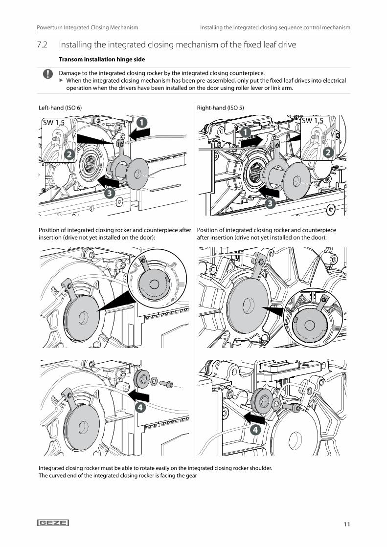
7.2 Installing the integrated closing mechanism of the fixed leaf drive
Transom installation hinge side
Damage to the integrated closing rocker by the integrated closing counterpiece. X When the integrated closing mechanism has been pre-assembled, only put the fixed leaf drives into electrical
operation when the drivers have been installed on the door using roller lever or link arm.
Left-hand (ISO 6) Right-hand (ISO 5)
SW 1,5
2
1
3
SW 1,5
2
1
3
Position of integrated closing rocker and counterpiece after insertion (drive not yet installed on the door):
Position of integrated closing rocker and counterpiece after insertion (drive not yet installed on the door):
4
4
Integrated closing rocker must be able to rotate easily on the integrated closing rocker shoulder.The curved end of the integrated closing rocker is facing the gear

Powerturn Integrated Closing Mechanism
12
Installing the integrated closing sequence control mechanism
Transom installation opposite hinge side
Damage to the integrated closing rocker by the integrated closing counterpiece. X When the integrated closing mechanism has been pre-assembled, only put the fixed leaf drives into electrical
operation when the drivers have been installed on the door using roller lever or link arm.
Left-hand (ISO 6) Right-hand (ISO 5)
SW 1,5
2
1
3
SW 1,5
2
1
3
Position of integrated closing rocker and counterpiece after insertion (drive not yet installed on the door):
Position of integrated closing rocker and counterpiece after insertion (drive not yet installed on the door):
4
4
Integrated closing rocker must be able to rotate easily on the integrated closing rocker shoulder.
The curved end of the integrated closing rocker is facing the gear.
Size 1.5 Size 1.5

Powerturn Integrated Closing Mechanism
13
Installing the integrated closing sequence control mechanism
7.3 Connecting the integrated closing mechanism of active and fixed leaf X Install the drives and levers. See the Powerturn installation instructions for details of drive installation.
Connection of the active and fixed leaf drive:
1
2
Fixed leaf (1) Active leaf (2)For wire cable connection see chapter 6.2 “Drive unit with pre-assembled integrated closing sequence control mechanism”.
Route of wire cable fixed leaf drive hinge side Left-hand (ISO 6):
Route of wire cable fixed leaf drive hinge side Right-hand (ISO 5):
Route of wire cable fixed leaf drive opposite hinge sideLeft-hand (ISO 6):
Route of wire cable fixed leaf drive opposite hinge sideRight-hand (ISO 5):

Powerturn Integrated Closing Mechanism
14
Installing the integrated closing sequence control mechanism
X With continuous cover, remove the side parts.
X Drill passageways in side parts for divided cover:
Ø 2 mm
Route of wire cable near the control:
Position of setting lever with the brake closed: Position of setting lever with the brake opened:

Powerturn Integrated Closing Mechanism
15
Installing the integrated closing sequence control mechanism
Attach the wire cable and spring on the wire cable tensioner
1
2
3
1 2
4SW 1.5
Setscrew (1), tension spring (2)
5
3
Position of the setting lever (3) = brake opened, active leaf closing.

Powerturn Integrated Closing Mechanism
16
Installing the integrated closing sequence control mechanism
Set the retaining action of the integrated closing brake
SW 2,5
The correct setting of the entire integrated closing mechanism has been achieved when, with the brake closed and fixed leaf closed, the setting lever takes up the position as designated for the open brake.
The wire cable must be tensioned both with opened and closed integrated closing brake between the fixed and active leaf drive.
Size 1.5

Powerturn Integrated Closing Mechanism
17
Function check
8 Function check X Open the active and fixed leaves up to the waiting position. X Release the fixed and active leaves.
The fixed leaf must start the closing movement immediately.The active leaf must remain in position until the brake is opened by the integrated closing mechanism on the fixed leaf.The active leaf closes.Further test requirements: see national/international standards and regulations.
9 CommissioningSee Powerturn installation instructions and wiring diagram for electrical connection, spring force setting and teaching process.
10 Service and after-sales service maintenance à The maintenance work on the closing sequence control must be carried out by an expert during the mainte-
nance cycle of the Powerturn drive. à See Powerturn installation instructions for maintenance instructions.
11 Troubleshooting For troubleshooting and fault elimination see the fault table in the wiring diagram, "Fault messages" section.


GermanyGEZE Sonderkonstruktionen GmbHPlanken 197944 Boxberg-SchweigernTel. +49 (0) 7930 9294 0Fax +49 (0) 7930 9294 10E-Mail: [email protected]
GEZE GmbHNiederlassung Süd-WestTel. +49 (0) 7152 203 594E-Mail: [email protected]
GEZE GmbHNiederlassung Süd-OstTel. +49 (0) 7152 203 6440E-Mail: [email protected]
GEZE GmbHNiederlassung OstTel. +49 (0) 7152 203 6840E-Mail: [email protected]
GEZE GmbHNiederlassung Mitte/LuxemburgTel. +49 (0) 7152 203 6888E-Mail: [email protected]
GEZE GmbHNiederlassung WestTel. +49 (0) 7152 203 6770 E-Mail: [email protected]
GEZE GmbHNiederlassung NordTel. +49 (0) 7152 203 6600E-Mail: [email protected]
GEZE Service GmbHTel. +49 (0) 1802 923392E-Mail: [email protected]
AustriaGEZE AustriaE-Mail: [email protected]
Baltic StatesGEZE GmbH Baltic States officeE-Mail: [email protected]
BeneluxGEZE Benelux B.V.E-Mail: [email protected]
BulgariaGEZE Bulgaria - Trade E-Mail: [email protected]
ChinaGEZE Industries (Tianjin) Co., Ltd.E-Mail: [email protected]
GEZE Industries (Tianjin) Co., Ltd.Branch Office ShanghaiE-Mail: [email protected]
GEZE Industries (Tianjin) Co., Ltd.Branch Office GuangzhouE-Mail: [email protected]
GEZE Industries (Tianjin) Co., Ltd.Branch Office BeijingE-Mail: [email protected]
FranceGEZE France S.A.R.L.E-Mail: [email protected]
HungaryGEZE Hungary Kft.E-Mail: [email protected]
IberiaGEZE Iberia S.R.L.E-Mail: [email protected]
IndiaGEZE India Private Ltd.E-Mail: [email protected]
ItalyGEZE Italia S.r.lE-Mail: [email protected]
GEZE Engineering Roma S.r.lE-Mail: [email protected]
PolandGEZE Polska Sp.z o.o.E-Mail: [email protected]
RomaniaGEZE Romania S.R.L.E-Mail: [email protected]
RussiaOOO GEZE RUSE-Mail: [email protected]
Scandinavia – SwedenGEZE Scandinavia ABE-Mail: [email protected]
Scandinavia – NorwayGEZE Scandinavia AB avd. NorgeE-Mail: [email protected]
Scandinavia – DenmarkGEZE DanmarkE-Mail: [email protected]
SingaporeGEZE (Asia Pacific) Pte, Ltd.E-Mail: [email protected]
South AfricaGEZE Distributors (Pty) Ltd.E-Mail: [email protected]
SwitzerlandGEZE Schweiz AGE-Mail: [email protected]
TurkeyGEZE Kapı ve Pencere SistemleriE-Mail: [email protected]
UkraineLLC GEZE UkraineE-Mail: [email protected]
United Arab Emirates/GCCGEZE Middle EastE-Mail: [email protected]
United KingdomGEZE UK Ltd.E-Mail: [email protected]
GEZE GmbHReinhold-Vöster-Straße 21–2971229 LeonbergGermany
Tel.: 0049 7152 203 0Fax.: 0049 7152 203 310www.geze.com