powerturn - geze€¦ · · 2015-02-11en ser manual 156539-01. powerturn 2 ... à operating,...
TRANSCRIPT
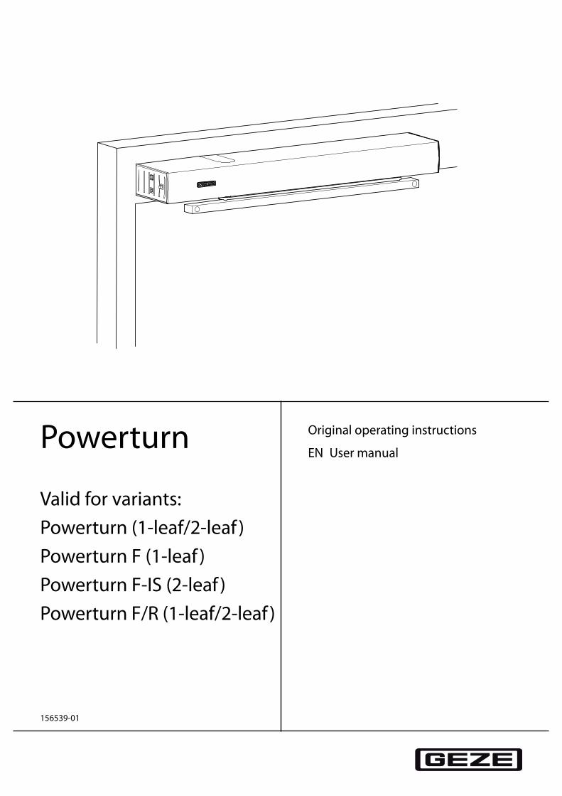
Powerturn
Valid for variants:Powerturn (1-leaf/2-leaf )Powerturn F (1-leaf )Powerturn F-IS (2-leaf )Powerturn F/R (1-leaf/2-leaf )
Original operating instructions
EN User manual
156539-01
Powerturn
2
Table of Contents
Symbols and illustrations ..................................................................................................................................................3
Product liability.....................................................................................................................................................................3
Special cases ..........................................................................................................................................................................3
1 General safety precautions ..................................................................................................................................41.1 Terms .....................................................................................................................................................................................................................4
2 Description ................................................................................................................................................................62.1 Types of installation and versions ...............................................................................................................................................................62.2 Composition .......................................................................................................................................................................................................6
3 Operation ...................................................................................................................................................................73.1 Functions .............................................................................................................................................................................................................73.2 Normal operation .............................................................................................................................................................................................73.3 Operating modes key and display ..............................................................................................................................................................83.4 Mechanical programme switch (MPS) (optional) ..................................................................................................................................93.5 Display programme switch (optional) .................................................................................................................................................... 10
4 Troubleshooting ................................................................................................................................................... 11
5 Cleaning and maintenance ............................................................................................................................... 125.1 Cleaning ............................................................................................................................................................................................................ 125.2 Service ................................................................................................................................................................................................................ 125.3 Testing by a competent expert ................................................................................................................................................................. 12
6 Technical data ........................................................................................................................................................ 13
Powerturn
3
Symbols and illustrations
Warning noticesWarning notices are used in these instructions to warn you of property damage and personal injury.
X Always read and observe these warning notices. X Follow all measures that are labelled with the warning symbol and warning word.
Warning symbol
Warning word Meaning
CAUTION Danger to persons. Non-observance can result in minor injuries.
More symbols and illustrationsIn order to illustrate proper operation, important information and technical information is highlighted.
Symbol Meaning
means "Important Information"; information to prevent property damage, to understand or optimise the operation sequences
means "Additional Information"
X Symbol for an action: There is something you must do here.
X Observe the order of multiple operational steps.
Product liabilityAccording to a manufacturer's liability for his products, as defined under product liability law, the information contained in this brochure (product information and proper usage, misuse, product performance, product main-tenance, information and instructional obligations) must be observed. Non-observance releases the manufac-turer from his liability.
Special casesIn certain cases, such as with à Special wiring à special function settings (parameters) à Special software
deviations from the information given in this user manual may occur. X If this is the case, please ask the service technician responsible.
Powerturn
4
General safety precautions
1 General safety precautions à Carefully read and abide by this user manual before commissioning the door. In addition, always observe the
following safety precautions: à Operating, maintenance and repair conditions specified by GEZE must be observed. à The commissioning, prescribed installation, maintenance and repair work must be performed by properly
trained personnel authorised by GEZE. à GEZE shall assume no liability for damage caused by unauthorised changes to the system. à The owner is responsible for safe operation of the system. If safety equipment is misaligned, thus preventing
it from fulfilling its intended purpose, further operation is not permissible. The service technician must be informed without delay.
à GEZE makes no guarantee for combinations with third-party products. Furthermore, only original GEZE parts may be used for repair and maintenance work.
à The connection to the power supply must be made by a professional electrician. à The main connection and protective conductor test must be performed according to DIN VDE 0100-610. à Use a customer-accessible 16-A overload cut-out that disconnects the system from the power supply as the
line-side disconnecting device. à Attach safety stickers to glass door leaves. à Protect the programme switch against unauthorised access. à In compliance with Machinery Directive 2006/42/EC, a risk analysis must be performed and the door system
identified in accordance with CE Marking Directive 93/68/EEC before the door system is commissioned. à Observe the current status of directives, standards and country-specific regulations, especially:
à ASR A1.7 "Directives for doors and gates" à DIN 18650 "Building hardware - Powered pedestrian doors" à DIN VDE 0100-610 "Erection of low-voltage installations" à DIN EN 60335-2-103 "Safety of electrical devices for home use and similar purposes; special requirements
for drives, for gates, doors and windows" à Accident-prevention regulations, especially BGV A1 "General regulations" and BGV A2 "Electrical systems
and equipment"
1.1 TermsTerm StatementHinge side The side of the door where the hinges from which the door leaf is suspended are
located. Usually that side of the door located in the opening direction.Opposite hinge side The side of the door that lies opposite the hinge side. Usually that side of the door
located in the closing direction.Active leaf The main leaf of a double-leaf door. The active leaf must open as the first door leaf and
close as the last door leaf when the door is used.Fixed leaf The secondary leaf of a double-leaf door. When the door is used, the fixed leaf may not
open until the active leaf has left the closing position and must close again as the first door leaf.
Inside contactor (KI) Button, switch or movement detector for controlling the door drive.The contactor is located within the room enclosed by the door.Control function in the AUTOMATIC and SHOP CLOSING-TIME operating modes.The contactor does not have any function in the NIGHT/OFF operating mode.
Outside contactor (KA) Button, switch or movement detector for controlling the door drive.The contactor is located outside the room enclosed by the door.Control function in the AUTOMATIC operating mode. The contactor does not have any function in the SHOP CLOSING-TIME and NIGHT/OFF operating modes.
Contactor authorised (KB)
Access control function (for example key-operated switch or card reader) used by authorised persons to control the door drive.The control function is active in the AUTOMATIC, SHOP CLOSING-TIME and NIGHT/OFF operating modes.
Contactor with current impulse function
Button for opening and closing the door. Control function only in the AUTOMATIC and SHOP CLOSING-TIME operating modes. The door is opened automatically when the button is first pressed and closed again automatically when the button is pressed the second time. The function can be activated during commissioning by setting param-eters using the display programme switch, ST 220 or GEZEconnects. If the contactor is connected to the fixed leaf control system by means of the "current impulse" function, both door leaves open when activated, even when the fixed leaf control system is deactivated.
Powerturn
5
General safety precautions
Term StatementPush&Go When the door is pressed manually out of the closing position with an activated Push &
Go function in the AUTOMATIC operating mode, the door opens automatically as soon as a specific adjustable opening angle is exceeded.
Open safety sensor (OSS) Presence detector (e.g. active infrared light sensor) for protecting the swinging range of the door in the opening direction. As a rule the sensor is located on the hinge side of the door on the door leaf.
Safety sensor close (SIS) Presence detector (e.g. active infrared light sensor) for protecting the swinging range of the door in the closing direction. As a rule the sensor is located on the opposite hinge side of the door leaf.
Emergency stop Self-locking switch with which immediate stopping of the door drive can be triggered in case of danger. The drive remains in its current position until the user releases the emergency stop switch again, thus terminating the emergency stop situation.
Door closing sequence selec-tor
Electrical door closing sequence selectorIn normal operation of double-leaf door drives, the closing sequence of the door leaves is controlled by the control units of the door drives, with the fixed leaf being closed first. The active leaf remains in the open position until the fixed leaf has reached the closed position, then the active leaf begins to close.Integrated door closing sequence selector (-IS)The closing sequence is controlled mechanically in the case of a power failure at dou-ble-leaf door systems with Powerturn F-IS. The door leaves are closed by means of the power storage of the drives, with the moveable leaf being kept open by the integrated mechanical close sequence control unit. When the fixed leaf has reached the closed position, it releases the active leaf by means of the mechanical elements of the door closing sequence selector so that it can also close completely.
Electrical door opener Open-circuit door openerAvailable as AC or DC door opener version. When the door drive is actuated, the door opener is activated by the control unit of the door drive provided the door is in the closed position. The door opener remains activated until the door has left the closed position.Static currentDC door opener version. The door opener is switched off when the door drive is acti-vated provided the door is in the closed position. The door opener remains switched off until the door has left the closed position.
Lock feedback The lock feedback function is a contact integrated in the door catch that is activated when the door is locked mechanically by the tie bolt of the door lock. It signals to the control unit that the door is locked mechanically and can therefore not be opened by the door drive. In this case the control unit ignores the control commands of all the contactors.
Reset Button for restarting the drive after the operating voltage has been switched on or after a fire alarm has been terminated. When the button is pressed, the self-retention integrated in the drive is activated, causing the drive to be activated.
Latching function When the door is closed in a de-energised state, the door leaf is impeded by the lock latch of the door opener. To make sure the door can pass the lock latch safely during closing, an integrated limit switch is actuated in the drive once a specific opening an-gle has been reached, reducing the braking strength. The door accelerates and closes into the lock at increased speed. In an energised state, this function is regulated by the drive control unit.
Powerturn
6
Description
2 Description
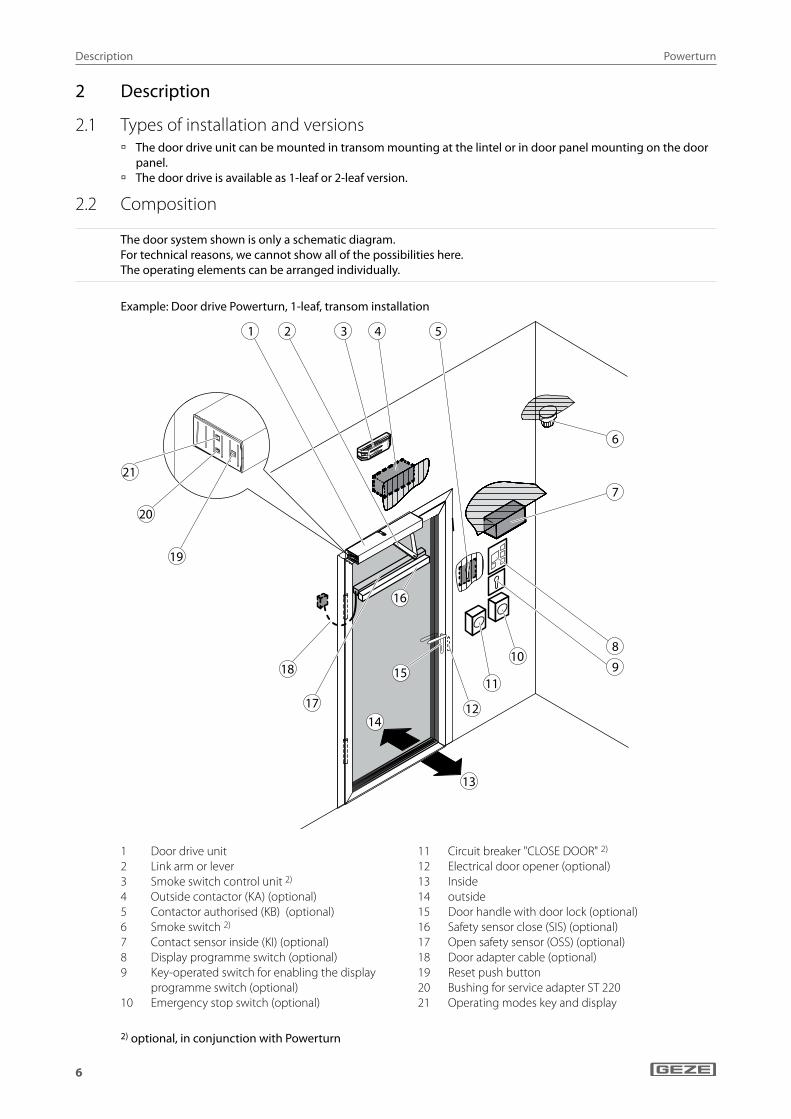
2.1 Types of installation and versions à The door drive unit can be mounted in transom mounting at the lintel or in door panel mounting on the door
panel. à The door drive is available as 1-leaf or 2-leaf version.
2.2 Composition
The door system shown is only a schematic diagram.For technical reasons, we cannot show all of the possibilities here.The operating elements can be arranged individually.
Example: Door drive Powerturn, 1-leaf, transom installation
��
��
��
��
��
��
� � � � �
�
�
�
���
��
��
��
��
��
1 Door drive unit2 Link arm or lever3 Smoke switch control unit 2)
4 Outside contactor (KA) (optional)5 Contactor authorised (KB) (optional)6 Smoke switch 2)
7 Contact sensor inside (KI) (optional)8 Display programme switch (optional)9 Key-operated switch for enabling the display
programme switch (optional)10 Emergency stop switch (optional)
11 Circuit breaker "CLOSE DOOR" 2)
12 Electrical door opener (optional)13 Inside14 outside 15 Door handle with door lock (optional)16 Safety sensor close (SIS) (optional)17 Open safety sensor (OSS) (optional) 18 Door adapter cable (optional)19 Reset push button 20 Bushing for service adapter ST 22021 Operating modes key and display
2) optional, in conjunction with Powerturn
Powerturn
7
Operation
3 Operation
3.1 Functions
The set parameters of the drive functions may only be modified by properly trained persons.
The commissioning and setting or changing of door parameters and some special drive functions can be done using the display programme switch, ST 220 or GEZEconnects.Querying and modifying of the set drive parameters are described in the circuit diagram.
3.2 Normal operation
In certain cases, e.g. with special wiring, special function settings (parameters), special software, deviations from the information given in this manual can occur. If this is the case, please ask the service technician responsible.
In normal door operation, the door is automatically opened and closed.
What happens? What does the door do?A contactor (button, switch or movementdetector) is triggered.
Door opens, waits the hold-open time and then closes.
Safety sensor close (SIS) is triggered when the door is open (e.g. light switch).
Door remains open.
Safety sensor close (SIS) is triggered while the door is clos-ing.
The door immediately opens again depending on the parameter adjustment.
Safety sensor open (SIO) is triggered while door is opening. The door stops and remains in the position until the end of actuation (door opens) or until the end of the hold-open time (door closes).
Safety sensor open (SIO) is triggered when the door is closed.
Door remains closed.
A person moves toward the opened door and a movement detector is activated.
Door remains open.
A person moves toward the closing door and a movement detector is activated.
Door reopens immediately.
Door contacts an obstruction when opening. Door stops, waits and attempts again to move to the open position at a reduced speed.Then the door closes again.
Door contacts an obstruction when closing. Door reopens immediately, waits the hold-open time and then closes at a reduced speed.
Additional door functions
Which switch/button? What does the switch/button do?Emergency stop switch The door stops immediately (in every operating mode)
and holds the position until the emergency stop switch is unlocked.
Key-operated switch of the display programme switch If a key-operated switch is connected to the display pro-gramme switch, the operation of the display programme switch can be locked or released with it.
Contactor authorised (KB) (e.g. outside key-operated switch)
Door opens once and closes after the hold-open time. The set operating mode is retained.
Powerturn
8
Operation
3.3 Operating modes key and display
Changing the operating mode (with single-leaf doors or active leaves) X Press the operating modes key (21) briefly.
The operating modes display immediately switches one mode of operation further. The drive itself does not change the mode of operation to the new mode of operation until 1 s after the last key has been pressed.Operating modes sequence:… OFF Night Shop closing Automatic Permanently open OFF Night …Thanks to the 1 s delay it is possible to change the mode of operation from AU (automatic) through DO (perma-nently open) to NA (night) without the door opening in the (briefly actuated) DO (permanently open) setting.
à In normal mode, the operating modes display lights up in the colour of the current mode of operation. à If the control has not been taught at this point, the operating modes display lights up yellow (light on perma-
nently). à If the control has not been initialised yet, the operating modes display lights up in the colour of the current
mode of operation, periodically interrupted by two short flashing impulses (1 Hz). à If one or more faults are pending, the operating modes display flashes quickly (10 Hz) in the colour of the cur-
rent mode of operation. à In the OFF mode of operation, there is no fault display on the operating modes display. à If the parameter "switch-off internal operating modes key" AB is set, the integrated operating modes switch
(21) is disabled and the integrated operating modes display (21) is switched off. à If the setting is changed from enabled to disabled or vice versa, the operating modes display flashes yellow for
3 s – the setting has been accepted. Then the operating modes display is off. à When the operating modes push button (21) is actuated again, the operating modes display (21) flashes for 3 s
in red – operation is not accepted.
Changing the mode of operation (fixed leaves)The drive on the fixed leaf is switched on and off using the on/off switch.When the drive is switched on, the operating modes display (21) lights up in the colour of the mode of operation (see below).If the drive is switched off, the operating modes display (21) does not light up.
Operating mode Colour of the operating modes display (21)
OFF (off) –NA (night) redLS (shop closing) whiteAU (automatic) greenDO (permanently open) blue

Powerturn
9
Operation
3.4 Mechanical programme switch (MPS) (optional)
à Additionally, it can be connected to the internal operating modes key.
At the mechanical programme switch, the system operating mode is selected and the corresponding programme is displayed.The mechanical programme switch is accessible for everyone without a key-operated switch.
The mechanical programme switch MPS-ST must be used for disa-bling.The desired operating mode is selected by using the rotary switch.
Mechanical programme switch MPS
At the mechanical programme switch MPS-ST, the system operating mode is selected and the corresponding programme is displayed.Operation of the mechanical programme switch MPS-ST is only pos-sible with the supplied key.Disabling the mechanical programme switch MPS-ST:
X Remove the key.The desired operating mode is selected by using the key-operated rotary switch.
Mechanical programme switch MPS-ST with integrated key-operated switch
Operating condition MPSMPS-ST
Explanatory notes
Automatic Door opens and closes again.The inside and outside contactors are active.
à Opening of 2 leaves At 2-leaf systems: X Switch to opening of 2 leaves in all operating modes.
With MPS, MPS-ST X Select the opening of 2 leaves at the corresponding position.
à Opening of 1 leaf Switch to opening of 1 leaf in all operating modes:With MPS, MPS-ST
X Select the opening of 1 leaf at the corresponding position.
Shop closing Door only opens and closes if someone exits.
Permanently open Door remains open.
Night Door opens and closes only when actuated using the key-operated switch
Fixed leaf On / Off Door is enabled and can be moved by hand.

Powerturn
10
Operation
3.5 Display programme switch (optional)
à Additionally, it can be connected to the internal operating modes key.
If a dot appears in the bottom right-hand part of the display, maintenance is due.
X Notify a service technician.
OFF
Display programme switch
If a dot appears in the middle of the display, the door has not yet been fully initialised after the mains voltage has been switched on.Initialisation is carried out automatically when the drive opens and closes the door.
Operating mode Key Display Explanatory notesAutomatic aU Door opens and closes again.
Inside and outside contactors active.
à Opening of 2 leaves With 2-leaf AppendicesSwitch to opening of 2 leaves in all operating modes:
X Select the opening of 2 leaves at the corresponding position.
à Opening of 1 leaf With 1-leaf AppendicesSwitch to opening of 1 leaf in all operating modes:
X Select the opening of 1 leaf at the corresponding position.
Shop closing ls Door only opens and closes if someone exits.Only inner contactor active.
Permanently open DO Door remains open.
Night Na Door opens and closes only when actuated using the key-operated switch
OFFDoor is enabled and can be moved by hand.
Setting the languageThe displayed language can be set in the service menu of the display programme switch.Available languages: German, English, French and Italian.
Fault messages on the displayIf a fault occurs in the door system, it is displayed on the display programme switch about every 10 seconds.
X Read off the number of the fault message, note it down and notify the service technician.
Powerturn
11
Troubleshooting
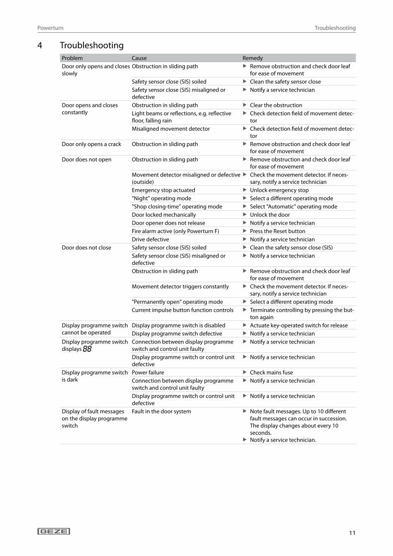
4 TroubleshootingProblem Cause RemedyDoor only opens and closes slowly
Obstruction in sliding path X Remove obstruction and check door leaf for ease of movement
Safety sensor close (SIS) soiled X Clean the safety sensor closeSafety sensor close (SIS) misaligned or defective
X Notify a service technician
Door opens and closes constantly
Obstruction in sliding path X Clear the obstructionLight beams or reflections, e.g. reflective floor, falling rain
X Check detection field of movement detec-tor
Misaligned movement detector X Check detection field of movement detec-tor
Door only opens a crack Obstruction in sliding path X Remove obstruction and check door leaf for ease of movement
Door does not open Obstruction in sliding path X Remove obstruction and check door leaf for ease of movement
Movement detector misaligned or defective (outside)
X Check the movement detector. If neces-sary, notify a service technician
Emergency stop actuated X Unlock emergency stop"Night" operating mode X Select a different operating mode"Shop closing-time" operating mode X Select "Automatic" operating modeDoor locked mechanically X Unlock the doorDoor opener does not release X Notify a service technicianFire alarm active (only Powerturn F) X Press the Reset buttonDrive defective X Notify a service technician
Door does not close Safety sensor close (SIS) soiled X Clean the safety sensor close (SIS)Safety sensor close (SIS) misaligned or defective
X Notify a service technician
Obstruction in sliding path X Remove obstruction and check door leaf for ease of movement
Movement detector triggers constantly X Check the movement detector. If neces-sary, notify a service technician
"Permanently open" operating mode X Select a different operating modeCurrent impulse button function controls X Terminate controlling by pressing the but-
ton againDisplay programme switch cannot be operated
Display programme switch is disabled X Actuate key-operated switch for releaseDisplay programme switch defective X Notify a service technician
Display programme switch displays 88
Connection between display programme switch and control unit faulty
X Notify a service technician
Display programme switch or control unit defective
X Notify a service technician
Display programme switch is dark
Power failure X Check mains fuseConnection between display programme switch and control unit faulty
X Notify a service technician
Display programme switch or control unit defective
X Notify a service technician
Display of fault messages on the display programme switch
Fault in the door system X Note fault messages. Up to 10 different fault messages can occur in succession. The display changes about every 10 seconds.
X Notify a service technician.
Powerturn
12
Cleaning and maintenance
5 Cleaning and maintenance
CAUTION!Danger of injury due to impact and crushing!
X Disconnect the drive from the 230 V mains network before carrying out cleaning work. X Secure door leaves against accidental movement before carrying out cleaning work. X Installation, maintenance and repair work must be performed by properly trained personnel authorised by
GEZE.
5.1 CleaningWhat is to be cleaned? How is it to be cleaned?Safety sensor close (SIS) (e.g. light sensors) X Wipe with damp clothGlass surfaces X Wipe with a cold vinegar/water mixture; then dry.Stainless surfaces X Wipe with soft clothPainted surfaces X Wipe with water and soapAnodised surfaces X Wipe with non-alkaline potassium soap (pH value 5.5…7)Display programme switch X Wipe with soft cloth. Do not use a cleaning agent
5.2 ServiceThe owner must ensure that the system functions properly. To guarantee perfect operation, the door system must be serviced regularly by a service technician.Maintenance must be carried out at least once a year or according to the maintenance display on the display programme switch.
If a dot appears in the bottom right-hand part of the display, maintenance is due. X Notify a service technician.
GEZE offers maintenance contracts with the following services: à Inspection of fastening elements for firm fit à Performance of miscellaneous adjustment work à Performance of operational checks à Checking all the safety and control equipment of the door system à Lubrication of all the moveable parts
5.3 Testing by a competent expertIn accordance with the "Guidelines for windows, doors and gates" (ASR A1.7 and GUV 16.10) Section 6, power-operated doors must be inspected for safety by a trained professional before initial commissioning and at least once a year.GEZE offers the following services:Inspection and operational checks of all safety and control equipment in accordance with the requirements in the test log for power-operated windows, doors and gates; Sliding doors and sliding gates ZH 1/580.2 edition.
Powerturn
13
Technical data
6 Technical dataOpening time: 3 … 25 s
Closing time: 5 … 25 s
Mains voltage 230 V AC ±10 %
Frequency 50 Hz
Protection rating I
Nominal capacity 200 W
Mains connection Fixed connection (installation cable or cable transition)
Primary fuse –
Secondary fuse 10 A slow-blow, 5×20 mm
Secondary voltage (transformer) 33 V AC (46 V DC)
Control voltage for external compo-nents
24 V DC ±5 %
Output current control voltage 24 V 1200 mA permanently 1800 mA briefly (2 s, duty ratio 30 %)
Fuse protection <24 V 2.5 A; reversible
Temperature Range –15 … +50 °C
IP rating IP30

Powerturn
14
Cleaning and maintenance

Powerturn
15
Cleaning and maintenance
GermanyGEZE Sonderkonstruktionen GmbHPlanken 197944 Boxberg-SchweigernTel. +49 (0) 7930 9294 0Fax +49 (0) 7930 9294 10E-Mail: [email protected]
GEZE GmbHNiederlassung Süd-WestTel. +49 (0) 7152 203 594E-Mail: [email protected]
GEZE GmbHNiederlassung Süd-OstTel. +49 (0) 7152 203 6440E-Mail: [email protected]
GEZE GmbHNiederlassung OstTel. +49 (0) 7152 203 6840E-Mail: [email protected]
GEZE GmbHNiederlassung Mitte/LuxemburgTel. +49 (0) 7152 203 6888E-Mail: [email protected]
GEZE GmbHNiederlassung WestTel. +49 (0) 7152 203 6770 E-Mail: [email protected]
GEZE GmbHNiederlassung NordTel. +49 (0) 7152 203 6600E-Mail: [email protected]
GEZE Service GmbHTel. +49 (0) 1802 923392E-Mail: [email protected]
AustriaGEZE AustriaE-Mail: [email protected]
Baltic StatesGEZE GmbH Baltic States officeE-Mail: [email protected]
BeneluxGEZE Benelux B.V.E-Mail: [email protected]
BulgariaGEZE Bulgaria - Trade E-Mail: [email protected]
ChinaGEZE Industries (Tianjin) Co., Ltd.E-Mail: [email protected]
GEZE Industries (Tianjin) Co., Ltd.Branch Office ShanghaiE-Mail: [email protected]
GEZE Industries (Tianjin) Co., Ltd.Branch Office GuangzhouE-Mail: [email protected]
GEZE Industries (Tianjin) Co., Ltd.Branch Office BeijingE-Mail: [email protected]
FranceGEZE France S.A.R.L.E-Mail: [email protected]
HungaryGEZE Hungary Kft.E-Mail: [email protected]
IberiaGEZE Iberia S.R.L.E-Mail: [email protected]
IndiaGEZE India Private Ltd.E-Mail: [email protected]
ItalyGEZE Italia S.r.lE-Mail: [email protected]
GEZE Engineering Roma S.r.lE-Mail: [email protected]
PolandGEZE Polska Sp.z o.o.E-Mail: [email protected]
RomaniaGEZE Romania S.R.L.E-Mail: [email protected]
RussiaOOO GEZE RUSE-Mail: [email protected]
Scandinavia – SwedenGEZE Scandinavia ABE-Mail: [email protected]
Scandinavia – NorwayGEZE Scandinavia AB avd. NorgeE-Mail: [email protected]
Scandinavia – DenmarkGEZE DanmarkE-Mail: [email protected]
SingaporeGEZE (Asia Pacific) Pte, Ltd.E-Mail: [email protected]
South AfricaGEZE Distributors (Pty) Ltd.E-Mail: [email protected]
SwitzerlandGEZE Schweiz AGE-Mail: [email protected]
TurkeyGEZE Kapı ve Pencere SistemleriE-Mail: [email protected]
UkraineLLC GEZE UkraineE-Mail: [email protected]
United Arab Emirates/GCCGEZE Middle EastE-Mail: [email protected]
United KingdomGEZE UK Ltd.E-Mail: [email protected]
GEZE GmbHReinhold-Vöster-Straße 21–2971229 LeonbergGermany
Tel.: 0049 7152 203 0Fax.: 0049 7152 203 310www.geze.com