power xpert® multi-point meter user manual...2 user manual mn150001en effective july 2019 power...
TRANSCRIPT
Effective July 2019Supersedes July 2017User Manual MN150001EN
Power Xpert® Multi-Point MeterUser Manual
ContentsDescription Page
1: Introduction . . . . . . . . . . . . . . . . . . . . . . . . . . . 2 1 .1 Safety Precautions . . . . . . . . . . . . . . . . . . 2 1 .2 Product Overview . . . . . . . . . . . . . . . . . . . 2 1 .3 Ordering Information . . . . . . . . . . . . . . . . . 2 1 .4 Metering Compatibility . . . . . . . . . . . . . . . 4 1 .5 Component Overview . . . . . . . . . . . . . . . . 4 1 .6 Symbols . . . . . . . . . . . . . . . . . . . . . . . . . . 62: Hardware Overview . . . . . . . . . . . . . . . . . . . . . 6
2 .1 General Overview . . . . . . . . . . . . . . . . . .6 2 .2 Power Xpert Multi-Point Meter
(PXMP Meter) . . . . . . . . . . . . . . . . . . . . .73: PXMP Configuration Software Overview . . . . 17 3 .1 Demand Recording . . . . . . . . . . . . . . . . . 194: Power Xpert Multi-Point Meter (PXMP Meter) . Installation . . . . . . . . . . . . . . . . . . . . . . . . . . . 19 4 .1 Introduction . . . . . . . . . . . . . . . . . . . . . . 19 4 .2 Installing a Meter, Pulse Input, Digital
Output, and/or Energy Portal Module in the Meter Base Assembly . . . . . . . . . . . 20
4 .3 Installing the Meter Base Assembly in the Enclosure . . . . . . . . . . . . . . . . . . . . . 21
4 .4 Recommended Wiring Connections . . . . 285: Serial Communications Setup . . . . . . . . . . . . 37 5 .1 PXMP Meter Communications . . . . . . . 37 5 .2 PXMP Meter Communications
Information . . . . . . . . . . . . . . . . . . . . . . . 396: Configuring and Commissioning . . . . . . . . . . 397: Maintenance and Cleaning Instructions . . . . . 398: Reading Meter Settings and Data Via
the Optional PXMP Display . . . . . . . . . . . . . . 39Appendix A: Specifications . . . . . . . . . . . . . . . . . 40 A .1 Environmental . . . . . . . . . . . . . . . . . . . . 40 A .2 External Circuit Group Specifications . . . 40Appendix B: Modbus Registers . . . . . . . . . . . . . 44Appendix C: PXMP DIP Switch Permissions . . . . 59Appendix D: Glossary, and Acronyms . . . . . . . . . 60 D .1 Glossary . . . . . . . . . . . . . . . . . . . . . . . . . 60 D .2 Power Xpert Multi-Point Meter Acronyms . . . . . . . . . . . . . . . . . . . . . . . . 61 D .3 External Circuit Groups . . . . . . . . . . . . . 62Index: . . . . . . . . . . . . . . . . . . . . . . . . . . . . . . . . . . 63

2
User Manual MN150001ENEffective July 2019
Power Xpert® Multi-Point MeterUser Manual
EATON www.eaton.com
1: Introduction1.1 Safety Precautions
All safety codes, safety standards, and/or regulations must be strictly observed in the installation, operation, and maintenance of this device .
c WARNINGS THE WARNINGS AND CAUTIONS INCLUDED AS PART OF THE PROCEDURAL STEPS IN THIS DOCUMENT ARE FOR PERSONNEL SAFETY AND PROTECTION OF EQUIPMENT FROM DAMAGE. AN EXAMPLE OF A TYPICAL WARNING CALL-OUT IS SHOWN ABOVE. THIS WILL HELP TO ENSURE THAT PERSONNEL ARE ALERT TO WARNINGS THAT MAY APPEAR THROUGHOUT THE DOCUMENT. IN ADDITION, CAUTIONS ARE ALL UPPER CASE AND BOLDFACED AS SHOWN BELOW.
c WARNING COMPLETELY READ AND UNDERSTAND THE MATERIAL PRESENTED IN THIS DOCUMENT BEFORE ATTEMPTING INSTALLATION, OPERATION, OR APPLICATION OF THE EQUIPMENT. ONLY QUALIFIED PERSONS SHOULD BE PERMITTED TO PERFORM ANY WORK ASSOCIATED WITH THE EQUIPMENT. THE WIRING, INSTALLATION AND APPLICATION USE INSTRUCTIONS PRESENTED IN THIS DOCUMENT MUST BE FOLLOWED PRECISELY.. FAILURE TO DO SO COULD CAUSE PERMANENT EQUIPMENT DAMAGE, BODILY INJURY, OR DEATH.
c WARNING DO NOT ATTEMPT TO INSTALL OR PERFORM MAINTENANCE ON EQUIPMENT WHILE IT IS ENERGIZED. DEATH, SEVERE PERSONAL INJURY, OR SUBSTANTIAL PROPERTY DAMAGE CAN RESULT FROM CONTACT WITH ENERGIZED EQUIPMENT. ALWAYS VERIFY THAT NO VOLTAGE IS PRESENT BEFORE PROCEEDING WITH THE TASK, AND ALWAYS FOLLOW GENERALLY ACCEPTED SAFETY PROCEDURES. EATON IS NOT LIABLE FOR THE MISAPPLICATION OR MISINSTALLATION OF ITS PRODUCTS.
Figure 1. Components of the PXMP Meter.
1.2 Product Overview
The Eaton Power Xpert® Multi-Point Meter (PXMP Meter) offers a highly modular approach to high density metering applications in electrical power distribution equipment . The PXMP Meter is com-patible with most 3-phase industrial, commercial, and single-phase residential low voltage electrical power systems . Typical applications include feeder and branch circuit load monitoring found in switch and panel boards, however higher level voltage metering is possible with interposing load sensors and potential transformers . The modularity of the PXMP Meter allows this metering system to be customized to suit each metering installation based on the number and type of circuits to be metered . Up to 10 different PXMP Meter Modules (PXMP-MMs) can be mixed and matched within a PXMP Meter Base (PXMP-MB) to accommodate a total of up to 60 poles of metering channels from a variety of 1, 2, and 3 pole loads .
Various meter modules can be mixed and matched in a single PXMP Meter Base with support for split core sensors, solid core sensors, or both based on the circuits that need to be metered . In addition, PXMP Pulse Input Modules (PXMP-PIMs) can be installed into a PXMP Meter base for pulse metering from other electricity, gas, water, air, or steam meters .
Output modules are available for either remote control over Modbus or automatic control by the PXMP Meter based on customer config-ured threshold triggers . A PXMP Energy Portal Module (PXMP-EPM) is available that can make metered data available to individual ten-ants via an embedded WEB server . The Energy Portal module also supports a variety of protocols including Modbus TCP, SMTP, SNMP, SFTP, HTTP, HTTPS, and more . In addition to Ethernet, the Energy Portal Module supports an optional dial up telephone connection for interface with remote billing software . A Touch Screen Display is available for local display of metered data from any circuit .
1.3 Ordering Information
The PXMP Meter system offers the flexibility to be used in a variety of applications and can be customized, using the modular compo-nents, to fit most installations . Table 1 lists the modular components available for the PXMP Meter system .

3
User Manual MN150001ENEffective July 2019
Power Xpert® Multi-Point MeterUser Manual
EATON www.eaton.com
Table 1. PXMP Meter System – Modular Components.Catalog Number Description
PXMP-MB Meter Bases
PXMP-MB* PXMP Meter Base - 3PH/1PH 2W w/ ABCN Voltage Inputs
PXMP-MB-AB** PXMP Meter Base - 1PH 3W w/ ABN Voltage Inputs
PXMP-MMXXXXX Meter Modules
PXMP-MM10MA PXMP Meter Module w/ 6 10 mA Inputs
PXMP-MM100MA PXMP Meter Module w/ 6 100 mA Inputs
PXMP-MM333MV PXMP Meter Module w/ 6 333 mV Inputs
PXMP-MM10MA-AB PXMP Meter Module w/ 6 10 mA Inputs - 1 PH 3W
PXMP-MM100MA-AB PXMP Meter Module w/ 6 100 mA Inputs - 1 PH 3W
PXMP-MM333MV-AB PXMP Meter Module w/ 6 333 mV Inputs - 1 PH 3W
PXMP-PIM PXMP Meter Pulse Input Module w/ 8 Inputs
PXMP-DOM PXMP Meter Digital Output Module w/ 8 Outputs
PXMP-EPM Energy Portal Modules
PXMP-EPM PXMP Meter Energy Portal Module
PXMP-EPM-M PXMP Meter Energy Portal Module w/ Modem
PXMP-CSXXX Current Sensors with 100 mA Max. Outputs
PXMP-CS125-3 PXMP CS125 Sensor (100 mA output) - Kit x 3
PXMP-CS250-3 PXMP CS250 Sensor (100 mA output) - Kit x 3
PXMP-CS400-3 PXMP CS400 Sensor (100 mA output) - Kit x 3
* = PXMP-MB only supports PXMP-MM10MA-AB, PXMP-MM100MA-AB, and PXMP-MM333MV-AB.
** = PXMP-MB-AB only supports PXMP-xxxxxxx-AB modules.
Catalog Number Description
CSXXX - Current Sensors with 10 mA Max. Outputs
CS070 Current Sensor Module 70 Amps (10 mA output) - Kit x 6
CS125 Current Sensor Module 125 Amps (10 mA output) - Kit x 3
CS200 Current Sensor Module 200 Amps (10 mA output) - Kit x 3
CS400 Current Sensor Module 400 Amps (10 mA output) - Kit x 3
CS005 Current Sensor Module 5 Amps (10 mA output) (For use with 5 Amp CTs) - Kit x 3Sensor Cables for PXMP-CSXXX and PXMP-IMXXX
PXMP-SC4-3 PXMP Sensor Cable, 4 Ft. (1.22 m) - (male/male) Kit x 3
PXMP-SC6-3 PXMP Sensor Cable, 6 Ft. (1.8 m) - (male/male) Kit x 3
PXMP-SC8-3 PXMP Sensor Cable, 8 Ft. (2.44 m) - (male/male) Kit x 3
PXMP-SC12-3 PXMP Sensor Cable, 12 Ft. (3.66 m) - (male/male) Kit x 3
PXMP-SC28-3 PXMP Sensor Cable, 28 Ft. (8.5 m) - (male/male) Kit x 3
Sensor Cable Extensions
PXMP-SCE8-3 PXMP Sensor Extension Cable, 8 Ft. (2.44 m) - (male/female) Kit x 3
PXMP-SCE16-3 PXMP Sensor Extension Cable,16 Ft. (4.88 m) - (male/female) Kit x 3(Current Sensor) Interface Modules
PXMP-IM333MV-3 PXMP Current Sensor Interface Module (for 333 mV) -Kit x 3
PXMP-IM100MV-3 PXMP Current Sensor Interface Module (for 100 ma) -Kit x 3
PXMP-DISP Display
PXMP-DISP-6-XV 6-inch Color Touch-Screen Interface, Preloaded and Optimized for Use with the PXMP-MB (-AB)
PXMP-DISP-6-TM 6-inch Color Touch-Screen Interface, Preloaded and Optimized for Use with the PXMP-MB (-AB), limited menu items - designed for tenant use.
PXMP-DISP6XV-DAT Replacement Cable - PXMP-DISP-6-XV
PX-PMBH-XV PXM-DISP-6 to PXM-DISP-6-XV Adapter Plate
24 Vdc Power Supplies
PSG60E 85-264 Vac 1-PH / 120-375Vdc Input, 24Vdc @2.5A (60W) Output
PSG120E 85-264 Vac 1-PH / 120-375Vdc Input, 24Vdc @5A (120W) Output
PSG240E 85-264 Vac 1-PH / 120-375Vdc Input, 24Vdc @10A (240W) Output
PSG480E 85-264 Vac 1-PH / 120-375Vdc Input, 24Vdc @20A (480W) Output
PSG60F 320-575 Vac 3-PH / 450-800Vdc Input, 24Vdc @2.5A (60W) Output
PSG120F 320-575 Vac 3-PH / 450-800Vdc Input, 24Vdc @5A (120W) Output
PSG240F 320-575 Vac 3-PH / 450-800Vdc Input, 24Vdc @10A (240W) Output
PSG480F 320-575 Vac 3-PH / 450-800Vdc Input, 24Vdc @20A (480W) Output
For more information on PSG Series DC Power Supplies go to; www .eaton .com > Products & Solutions > Electrical > Products & Services > Automation & Control > Power Supplies and Temperature Controllers > PSG series DC Power Supplies

4
User Manual MN150001ENEffective July 2019
Power Xpert® Multi-Point MeterUser Manual
EATON www.eaton.com
1.4 Metering Compatibility
See Appendix A for additional information .
Direct Mains Voltage Monitoring with the PXMP Meter is possible up to a system maximum rating of:• 480VL:G (corner grounded Delta)• 347VL:N & 600VL:L maximum for Wye applications• 480VL:G & L:L maximum on grounded Delta applications
Higher Voltage ratings or floating Delta applications will require the use of interposing potential transformers to stay within the PXMP maximum voltage ratings .
PXMP Load Current measurements are directly compatible with current sensor (instrument transformers) outputs in three ranges of secondary maximum outputs by using matching range PXMP Meter Modules:• 10 mA; • 100 mA; or• 333 mV .
Applications requiring 5A Current Transformer outputs require the use of the CS005 Class 10 Current Sensor as an interposing sen-sor which reduces the input to the meter module to <10ma . ANSI C12 .20 class 0 .5% accuracies may be achieved using either the Eaton CSXXX 10 mA or PXMP-CSXXX 100 mA current sensors and direct voltage metering . Interposing Potential and current transform-ers may introduce additional error .
The PXMP Meter supports a variety of current sensors . Eaton offers some sensors specially designed for use with our products . We also support the use of industry standard current sensors . When specify-ing current sensors, in general, note that: • Solid core sensors tend to have higher accuracy than split core
designs .• Split core sensors are often installed in Retrofit applications where
it is not practical to disconnect the load conductors in order to mount a solid core sensor .
• Current loop output sensors tend to have accuracy and noise immunity advantages over 333 mV output sensors .
• 333 mV sensors are very useful since they eliminate open circuit risks and are available in a wide range of primary current ratings .
• Eaton’s CS005 enables the PXMP Meter to interface to standard 5 A current transformers, either split core or solid core .
See sections 2 and 4 for details on sensors .
1.4.1 PXMP Meter System Power Requirements
The base PXMP Meter Base power supply input, Digital (Discrete) I/O External Circuit Groups, PXMP Pulse Input Module and Digital Output Module External Circuit Groups and Touch Screen Display are all designed to operate off external 24 Vdc (+/- 20%) sources . If all external circuits have no isolation conflicts, then a single 24 Vdc power supply can serve all of these power requirements . The choice of a proper supply must at least factor in the following requirements:• Total summation of system worst case power consumption;• System worst case ambient temperature within the enclosure;• Matching of supplies mains rating; and• Possible requirements for isolation between external circuit
groups (solution = multiple supplies) .• 24 Vdc source should be a local, dedicated bus for PXMP use
only . Do not connect to a CAT III DC bus .
1.4.2 Enclosure
The PXMP Meter must be housed in an enclosure that keeps the internal environment within the PXMP’s environmental specification ranges (See Appendix A) and provides User protection from hazard-ous circuits during normal operation .
1.5. Component Overview
Power Xpert Multi-Point Meter (PXMP Meter)
• There are two distinct Meter Bases and two distinct groups of Meter Modules for 3-phase and single-phase applications .
• The Meter Base is equipped with 256 MB of non-volatile memory for interval demand recording . Stores up to two years of 15 min-ute interval demand data (W For Demand, W Reverse Demand, Q1-Q4 kVAR Demand, Q1/Q4 kVA Demand, Q2/Q3 kVA Demand) .
• See Figures 50 through 61 for wiring examples .• Store up to two years of 15 minute interval demand and energy
recording:• W Forward demand (import)
• W Reverse demand (export)
• Q1 kVAR demand (inductive/motor load)
• Q2 kVAR demand (inductive generator)
• Q3 kVAR demand (Capacitive generator)
• Q4 kVAR demand (Capacitive load)
• Q1,Q4 KVA demand (import)
• Q2,Q3 KVA demand (export)
• Energy forward
• Energy reverse
PXMP Meter Modules (PXMP-MMs)
• Require that the current sensors be connected to a Meter Module input that correspnds to the matching phase voltage input on the meter base
• Monitor meter values and send them to processor on the Meter Base
• Plug into the PXMP Meter Base• Two distinct groups of Meter Modules for 3-phase and single-
phase applications .• Three standard Meter Modules 10 mA, 100 mA, and 333 mV .• Each Meter Module can be configured for up to six single pole
sub-meters, three two-pole sub-meters, or two three-pole sub-meters (or combinations not to exceed six poles) .
• All of the poles for a 2- or 3-pole meter must be on the same Meter Module . Meters cannot be configured to span across mul-tiple modules .
PXMP Current Sensors
• Three different types of current sensors can be used with the PXMP Meter based on secondary output type and range .• 10 mA sensors connect to 10 mA Meter Modules;
• 100 mA sensors connect to 100 mA Meter Modules; or
• 333 mV sensors connect to 333 mV Meter Modules .
• Interposing current transformers such as CS005 are used to con-nect 5 A CT to the PXMP Meter Module when CT's with a 5A secondary are used for primary current sensing .
• Current Sensing is directional/polarity sensitive and mounted on insulated load cables .
• PXMP Meter Modules are directly compatible with the CSXXX 10 mA and PXMP-CSXXX 100 mA current sensors corresponding to the Meter Module current input rating .

5
User Manual MN150001ENEffective July 2019
Power Xpert® Multi-Point MeterUser Manual
EATON www.eaton.com
• CSXXX 10 mA Current Sensors are used with the PXMP-MM10MA 10 mA Meter Module• 48” (1 .22 m) Sensor cables are built integral with the sensor .
• 8 ft and 12 ft (2 .44 and 3 .66 m) extension cables are available but do not exceed 20 ft total length .
• These sensors support 0 .5% accuracy .
• CS005 used to interface 5 A CT secondary to PXMP Meter Module, 5A Secondary CT adds additional error to PXMP mea-surements .
• No clamp alarm or Locator LEDs
• PXMP-CSXXX 100 mA current sensors are used with the PXMP-MM100MA 100 mA Meter Module• Equipped with a 4-position terminal plug therefore requires
the use of PXM-SC/SCE sensor cables to connect to PXMP-MM100MA 100 mA Meter Module .
• Maximum length not to exceed 28 ft (8 .54 m) .
• Equipped with Clamp Alarm LED and Locator LEDs .
• Supports identification and tamper detect circuit .
• These sensors, when used properly with Power Xpert Multipoint, will result in 0 .5% metering performance .
• Generic 333 mV or 100 mA current sensors must use the PXMP-IM333MV Interface Modules to interface with the PXMP Meter Module – this will also require a PXMP-SC Sensor Cable .
PXMP-IM333mV Interface Modules
• Used to interface 333 mV secondary output current sensors to PXMP Meter Modules .
PXMP-SC/SCEXX Sensor Cables
• Used to connect between PXMP-CSXXX or PXMP-IM and PXMP-MM's .
• Maximum length not to exceed 28 ft (8 .54 m) in order to avoid accuracy/burden issues .
PXMP Pulse Input Module (PXMP-PIM)
• Used to meter other utilities such as gas, water, and steam .• Can be configured for up to eight pulse meters .• Requirement for Input from Source Pulse
• Pulse type with voltage rating of 24 V +/- 20% or switchable intermediate conversion .
• Must be dry contact otherwise an interposing solid state relay is required to isolate PXMP .
• Can capture a pulse rate maximum of 20 Hz square wave• Pulse should be self-compensated for energy measurement• Requires a 24 Vdc power supply to provide exciting voltage for the
input circuit .• Pulse Input Module has a 2 .2 Kohm input impedance drawing
approximately 10 mA per closed input .
PXMP Digital Output Module (PXMP-DOM)
• Provides outputs to be used for control or indicate alarm condi-tions – typical installation might be for a building automation sys-tems .
• Digital Output Module can be controlled remotely via Modbus or driven by internal logic .
• Requires an external power source of 24 V +/- 20%• Each solid state relay supports maximum load of 80 mA .
PXMP Energy Portal Module (PXMP-EPM)
• Supported in slot 10 only .• Provides Web enabled metering capability .• PXMP-EPM-M supports internal dial up telephone modem .• Comes standard with front facing RJ-45 configuration port and
LAN/WAN RJ-45 Ethernet port .• Equipped with 2 GB of non-volatile memory and capable of stor-
ing over 10 years of tenant metering 15 minute interval demand data .
PXMP Touch Screen Display (PXMP-DISP-6-XV)
• Eaton XV-102-H4-57TVRL -10 programmed with PXMP display capabilities and 6 ft . (1 .8 m) cable .
• Provides means to view meter readings and view power system metering data .
• Cannot be used to configure PXMP Meter . PXMP Configuration requires PXMP Configuration Software .
PXMP Configuration Software
• JAVA application provided on CD accompanying the PXMP Meter Base . Can also be downloaded from Eaton web site .
• Supports Java 1 .7 or higher .• Connection of a laptop to the PXMP Meter Base, to configure the
PXMP Meter and Modules, can be accomplished through either the PXMP Meter Base USB port (Type B) or either Com 1 or Com 2 RS-485 Modbus .
• Wizard guides operator through configuration process .• Supports Online and Offline configuration session .• Refer to PXMP Configuration Software Manual MN150002EN for
details .
24 Vdc Power Source Required
• 24 Vdc required for PXMP-MB, PXMP-MB-AB, PXMP Pulse Input Module, PXMP Digital Output Module, and optional PXMP-DISP-6 .
• 24 Vdc power source must be adequate for total load at maximum anticipated ambient temperature .
• 24 Vdc power source must be matched to ratings of application’s source and provide isolation from mains .
The following maximum possible 24 Vdc loads need to be consid-ered in a PXMP Meter power system:
• 15 W - Meter Base 24 Vdc PS input;• 2 W - Meter Base digital Output x 1 on max . rated of 80 mA;• 1 W - Meter Base digital Inputs x 3 contact energized (dry contact
closed);• 9 .5 W - PXMP Display• 2 W - Per Pulse Input Module with all eight inputs energized (dry
contact closed);• 20 W worst case for ten cards;
• 15 .4 W - Per Digital Output Module with eight solid state outputs energized;• Worst case module load total is 154 W (based on 10 digital out-
put modules) .
6
User Manual MN150001ENEffective July 2019
Power Xpert® Multi-Point MeterUser Manual
EATON www.eaton.com
Eaton PSG family of power supplies are good match for most PXMP Meter applications:
• PSG E suffix, CPT style mains supplies and their output ratings:• PSG60E - 2 .5 Amp (60 W);• PSG120E - 5 Amp (120 W);• PSG240E - 10 Amp (240 W);• PSG480E - 20 Amp (480 W) .
PSG F suffix, 3-phase 400-500 VL:L rated Wye mains supplies and their output ratings:• PSG60F - 2 .5 Amp (60 W);• PSG120F - 5 Amp (120 W);• PSG240F - 10 Amp (240 W);• PSG480F - 20 Amp (480 W) .
otee:N All of the PSG series require de-rating above 50°C (122°F) to 50% load at 70°C (158°F) or below 0°C (32°F) to 80% at -20°C (-4°F) .
If any of the 24 Vdc external circuit groups require isolation from the other external circuit groups, then separate power supplies should be used to provide the needed isolation barrier .
1.6 Symbols
The following symbols are used in this PXMP Meter User manual .
Diode
Fuse
Protective Earth Ground
Resistor
Switch
c ELECTRICAL WARNINGe: Refers to instructions that, if not followed, can result in death or injury .
WARNINGe: Refers to instructions that, if not followed, can result in death or injury .
CAUTIONe: Refers to instructions that, if not followed, can result in equipment damage .
2: Hardware Overview2.1 General Overview
The Eaton Power Xpert Multi-Point Meter (PXMP Meter) offers a highly modular approach to high density metering applications in electrical power distribution systems . The modularity of the PXMP Meter allows this metering system to be customized to suit each metering installation based on the number and type of circuits to be metered . Up to 10 different PXMP Meter Modules (PXMP-MMs) can be mixed and matched within a PXMP Meter Base (PXMP-MB) to accommodate a total of up to 60 poles of metering channels from a variety of 1-, 2-, and 3-pole loads .
Various meter modules can be mixed and matched in a single Meter Base assembly with support for split core sensors, solid core sen-sors, or both based on the circuits that need to be metered . In addi-tion, PXMP Pulse Input Modules (PXMP-PIM) can be installed into a Meter base assembly for pulse metering from other electricity, gas, water, air, or steam meters .
PXMP Digital Output Modules (PXMP-DOMs) are available for either remote control over Modbus or automatic control by the PXMP Meter based on customer configured threshold triggers . A PXMP Energy Portal Module (PXMP-EPM) is available that can make metered data available to individual tenants via an embedded Web server . The Energy Portal Module supports individual Tenant User Names and Passwords to ensure that tenant access is limted only to authroized information . The Energy Portal Module also supports a variety of protocols including Modbus TCP, SMTP, SNMP, SFTP, HTTP, HTTPS, BACnet/IP, and more . In addition to Ethernet, the Energy Portal Module supports an optional dial up telephone connection for interface with remote billing software . A PXMP Touch Screen Display (PXMP-DISP-6-XV) is available for local display of metered data from any circuit .
Modules plug into the motherboard in the Meter Base assembly . They are secured with captive screws that, when tightened, ground the module to the Meter Base and to the earth ground stud .

7
User Manual MN150001ENEffective July 2019
Power Xpert® Multi-Point MeterUser Manual
EATON www.eaton.com
2.2 Power Xpert Multi-Point Meter (PXMP Meter)
2.2.1 PXMP Meter Base (PXMP-MB) Assembly
The PXMP Meter Base assembly comes in two configurations:• PXMP-MB (3-phase meter base that can support single-phase
metering) and• PXMP-MB-AB (single-phase meter base) Optimized for single
phase 3 wire electric supply voltage .
The PXMP-MB assembly, with no ”AB” suffix, is designed for meter-ing 3-phase Wye or Delta systems . It is designed to accommodate 3-phase systems and distributes 2 sets of 3-phase voltages to each meter module . The corresponding current sensor connections are indicated using the A1, B1, C1, A2, B2, C2 connection sequence designations on the white sequence label . It can also be used to support single-phase metering .
otee:N The PXMP-MB can be used on 3-Phase, 2-Phase, and single-phase applications as long as the current sensor inputs are matched with the volt-age sequencing as indicated on the white label . The PXMP-MB-AB can ONLY be used on single-phase applications where the supply voltage is single phase 3 wire .
Figure 2. PXMP-MB Assembly, Showing Cover Plates on All Module Locations.
The PXMP-MB-AB assembly is designed for metering residential single-phase service . It is designed to accommodate A1, B1, A2, B2, and A3, B3 sequences and has a yellow sequence label .
Figure 3. PXMP-MB-AB Assembly Populated with Three PXMP Meter Modules.
Yellow Label
Table 2 lists the system types supported by each PXMP Meter Base assembly .
Table 2. PXMP Meter Base Assemblies - Supported System Types.
Base Assembly Supported Systems
PXMP-MB 3-PH 3-Wire Delta (Grounded)Floating Delta Requires an Interposing Potential Transformer (PT)
3-PH 4-Wire Wye
Single-Phase Metering
PXMP-MB-AB 120/240 V, Single-Phase 3-Wire Service
Both PXMP Meter Base assembly models are shipped without modules . The front of the base has a label indicating 10 positions, or slots (1-10) where modules can be mounted . Each position is cov-ered with a metal slot cover secured to the assembly with screws . The slot covers protect the backplane of the Meter Base assembly . Slot covers are removed to insert modules, but should be left in place if the slot is not being used .
Figure 4. Meter Base Assembly as Shipped (PXMP-MB Shown).
otee:N Even though the voltage input label on the PXMP-MB-AB shows A, B, C, and N, the C connection will never be used in PXMP-MB-AB applications .
Figure 5. PXMP-MB-AB Voltage Input Label.
White Label

8
User Manual MN150001ENEffective July 2019
Power Xpert® Multi-Point MeterUser Manual
EATON www.eaton.com
The ten slots provided are multi-purpose . They can accommodate any combination of Meter Modules (10 mA, 100 mA, or 333 mV), Pulse Input Modules, or Digital Output Modules .
Normally, however, slot ten is reserved for the Energy Portal Module, described in Section 2 .2 .5 – PXMP Energy Portal Module (PXMP-EPM) . The Energy Portal Module is required for Ethernet and modem communications and advanced tenant metering functional-ity . The Energy Portal Module CAN ONLY be used in slot ten .
If slots one through nine are filled and a tenth Meter Module, Pulse Input Module, or Digital Output Module is required, the tenth slot can be used for that purpose . But, that will prevent the use of the Energy Portal Module and the functionality it provides .
The Meter Base assembly requires a 24 Vdc control power supply to operate . Usually, the power supply is mounted on a DIN rail in a common enclosure, as described in 4 .3 .3 - Installing a 24 Vdc Power Supply in the Enclosure .
The power supply 24 Vdc terminal plug fits into the terminal header on the right side of the Meter Base assembly . The power supply terminal includes an optional shield cable connection which can be used for enhanced EMC performance . Refer to Appendix A for power supply requirements .
Grounding of the system is required . A stud is provided on the Meter Base assembly for connection to an appropriate protective earth (PE) ground . Modules plugged into the motherboard in the Meter Base assembly are secured with captive screws that, when tightened, ground the module to the Meter Base assembly and to the earth ground .
Figure 6. 24 Vdc Input, Shield, and Ground Connections on the Meter Base Assembly.
Protective Earth (PE) Ground Stud
24 Vdc input Connections
Optional Shield
Metering voltage inputs connect to the right side of the PXMP-MB and PXMP-MB-AB assemblies . Inputs are marked A (V1), B (V2), C (V3), and N (VR) on both the PXMP-MB and PXMP-MB-AB assem-blies . If connecting to a Delta system, the unused N (VR) terminal should be connected to chassis ground . A cover for the voltage terminal is provided as a barrier to hazardous terminal access (see Figure 7) .
Figure 7. Meter Voltage Input Terminal Plug and Cover.
Figure 8. A, B, C, and N Connections on the PXMP-MB Assembly Meter Voltage Input.
otee:N On the PXMP-MB-AB, even though the voltage input label on the assembly lists the “C” connection, it will never be used in PXMP-MB-AB applications .
N
C
B
A
"N" Connections
"C" Connections
"B" Connections
"A" Connections

9
User Manual MN150001ENEffective July 2019
Power Xpert® Multi-Point MeterUser Manual
EATON www.eaton.com
Figure 9. Single-Phase 3-Wire 120/240 (Refer to Section 4.4, Figure 55 for more detailed drawing).
The Voltage Input connections are conditioned and distributed across the Meter Base assembly backplane to the Meter Module con-nectors . The relationship between the voltage terminal inputs and the current sensor inputs is hard wired . The circuit to be metered should be connected to the voltage input terminals following the wir-ing schematics in Section 4 .4 - Recommended Wiring Connections .
otee:N When commissioning a PXMP Meter, ensure that the phasing is con-sistent between the voltage input terminal and the load current sensor input connections on the Meter Modules . If a current sensor is plugged into a connection point on the Meter Module that is assigned to a different phase voltage, metering errors will result due to the current and voltage phasing mismatch (see Sections 4 .3 .4 - Current Sensor Installation and 6 - Configuring and Commissioning for detailed information) .
The Meter Base assembly includes a solid-state relay output that can be configured as a Pulse Initiator output assigned to any one of the tenant meters or to the aggregate sum of the tenant meters . An external local 24 Vdc power supply is required to drive the load lim-ited to 80 mA maximum . Use a local 24VDC local source dedicated to PXMP use, do not connect to a CAT III bus .
The Meter Base assembly also includes three digital status inputs that can be used to indicate conditions such as a demand synch pulse or a rate alert . These digital inputs require external 24 Vdc voltage +/- 20% to operate . Again use a local 24VDC source dedi-cated to PXMP use, do not connect to a CAT III bus .
The Mode DIP switches are located behind the metal door cover at the top left corner of the black label face of the Meter Base assem-bly panel . These Mode switches are used to secure the PXMP Meter in one of three levels of hardware enforced security modes . Note the tab off the base that can be used to seal the door shut for security purposes . Refer to Appendix C for detailed information .
100-240 VAC50-60 Hz125-250 VDC
Figure 10. Location of the Mode DIP and Communications Rotary Address Switches, Configuration and Coms Ports, and Digital Output and Inputs.
The slave USB connector supports a serial communications session with the PXMP Configuration Software . The software is described in Section 3 - Software Overview and is used to fully configure the PXMP Meter
The Meter Base assembly includes two RS-485 Modbus slave com-munication ports, Com 1 and 2, to permit connection to two dif-ferent Modbus Masters (refer to Appendix B - Modbus Registers) for details and a list of Modbus Registers and Section 5 on Serial Communications Setup .
The Meter Base assembly includes the following LED indicators (see Figure 11):• Three LEDs marked A, B, and C adjacent to the Meter Voltage
Input connector indicate if voltage is applied to the meter phase inputs and is within the expected range .
• Two LED’s are marked Delta or Wye/1PH and used to indicate the active metering mode configuration .
• Red and green TX and RX LED’s adjacent to Com 1 and Com 2 provide visual indication of Transmit and Receive activity on the communication ports .
• A Health LED indicates that the Meter Base main microprocessor is functioning correctly .
• A Power LED indicates that 24 Vdc is applied to the 24 Vdc input to the Meter Base .
• A Status LED indicates that communication activity between the Meter Base and Meter Modules .
The LEDs blink while connecting/reading information, are solid indi-cating the function is active, and are off when the function is not available .
Mode DIP Switches
Mode Cover Security Tab
USB Configuration Port
Commun- ication Rotary Address Switches
Digital SS Relay Output X!
Digital Inputs X3
Com1 Serial Port
Com2 Serial Port
10
User Manual MN150001ENEffective July 2019
Power Xpert® Multi-Point MeterUser Manual
EATON www.eaton.com
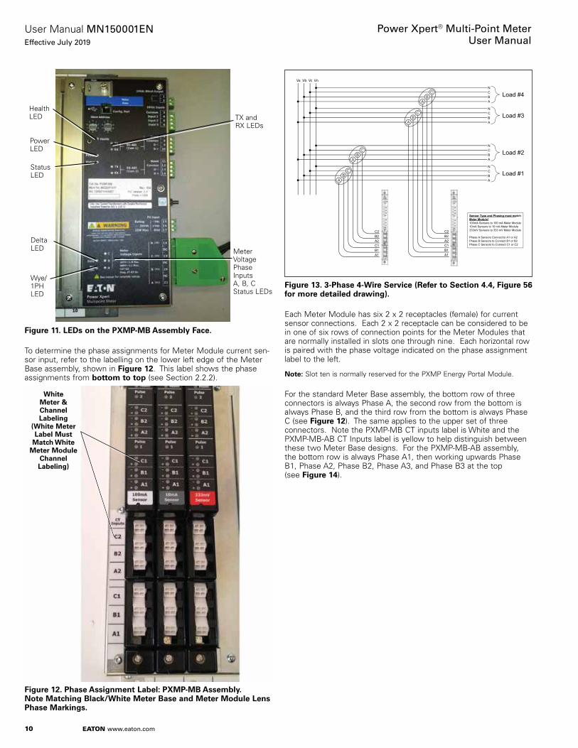
Figure 11. LEDs on the PXMP-MB Assembly Face.
To determine the phase assignments for Meter Module current sen-sor input, refer to the labelling on the lower left edge of the Meter Base assembly, shown in Figure 12 . This label shows the phase assignments from bottom to top (see Section 2 .2 .2) .
Figure 12. Phase Assignment Labele: PXMP-MB Assembly. Note Matching Black/White Meter Base and Meter Module Lens Phase Markings.
Health LED
Power LED
Status LED
Delta LED
Wye/ 1PH LED
TX and RX LEDs
Meter Voltage Phase Inputs A, B, C Status LEDs
White Meter & Channel Labeling
(White Meter Label Must
Match White Meter Module
Channel Labeling)
Figure 13. 3-Phase 4-Wire Service (Refer to Section 4.4, Figure 56 for more detailed drawing).
Each Meter Module has six 2 x 2 receptacles (female) for current sensor connections . Each 2 x 2 receptacle can be considered to be in one of six rows of connection points for the Meter Modules that are normally installed in slots one through nine . Each horizontal row is paired with the phase voltage indicated on the phase assignment label to the left .
otee:N Slot ten is normally reserved for the PXMP Energy Portal Module .
For the standard Meter Base assembly, the bottom row of three connectors is always Phase A, the second row from the bottom is always Phase B, and the third row from the bottom is always Phase C (see Figure 12) . The same applies to the upper set of three connectors . Note the PXMP-MB CT inputs label is White and the PXMP-MB-AB CT Inputs label is yellow to help distinguish between these two Meter Base designs . For the PXMP-MB-AB assembly, the bottom row is always Phase A1, then working upwards Phase B1, Phase A2, Phase B2, Phase A3, and Phase B3 at the top (see Figure 14) .
Va Vb Vc Vn
Sensor Type and Phasing must matchMeter Module!100mA Sensors to 100 mA Meter Module10mA Sensors to 10 mA Meter Module333mV Sensors to 333 mV Meter Module
Phase A Sensors Connect to A1 or A2Phase B Sensors to Connect B1 or B2Phase C Sensors to Connect C1 or C2
C
A
N
B
A1B1C1A2B2C2
A1B1C1A2B2C2
Load #4CB
A
CB
A
CB
A
CB
A
C
A
N
B Load #3
C
A
N
B Load #2
C
A
N
B Load #1
11
User Manual MN150001ENEffective July 2019
Power Xpert® Multi-Point MeterUser Manual
EATON www.eaton.com
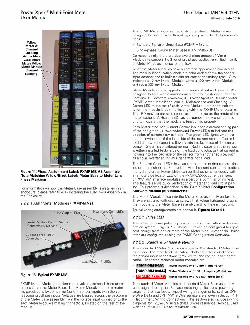
Figure 14. Phase Assignment Labele: PXMP-MB-AB Assembly. Note Matching Yellow/Black Labels Meter Base to Meter Lens Phase Markings.
For information on how the Meter Base assembly is installed in an enclosure, please refer to 4 .3 - Installing the PXMP-MB Assembly in the Enclosure .
2.2.2 PXMP Meter Modules (PXMP-MMs)
Figure 15. Typical PXMP-MM.
PXMP Meter Modules monitor meter values and send them to the processor on the Meter Base . The Meter Modules perform meter-ing calculations by combining Current Sensor inputs with the cor-responding voltage inputs . Voltages are bussed across the backplane of the Meter Base assembly from the voltage input connector to the each Meter Module’s mating connectors, located on the rear of the module .
Yellow Meter & Channel Labeling
(Yellow Meter Label Must
Match Yellow Meter Module
Channel Labeling)
Pulse Output LEDs Health and Com LEDs
Load Power +/- LEDs
Meter Module Current Sensor Compatibility Marking
Current Sensor Input Connections
The PXMP Meter includes two distinct families of Meter Bases designed for use in two different types of power distribution applica-tions:• Standard 3-phase Meter Base (PXMP-MB) and• Single-phase, 3-wire Meter Base (PXMP-MB-AB) .
Correspondingly, there are also two distinct groups of Meter Modules to support the 3- or single-phase applications . Each family of Meter Modules is described below .
All of the Meter Modules have a common appearance and design . The module identification labels are color coded above the sensor input connections to indicate current sensor secondary type . Grey indicates a 10 mA Meter Module, white a 100 mA Meter Module, and red a 333 mV Meter Module .
Meter Modules are equipped with a series of red and green LED’s designed to help with commissioning and troubleshooting (refer to Sections 3 – Software Overview, 4 – Power Xpert Multi-Point Meter (PXMP Meter) Installation, and 7 - Maintenance and Cleaning . A Comm LED at the top of each Meter Module turns on to indicate when the module is communicating with the PXMP Meter system . The LED may appear solid on or flash depending on the mode of the meter system . A Health LED flashes approximately once per sec-ond to indicate that the module is functioning properly .
Each Meter Module’s Current Sensor input has a corresponding pair of red and green -/+ reverse/forward Power LED’s to indicate the direction of current flow per load . The green LED lights when cur-rent is flowing out of the load side of the current sensor . The red LED lights when current is flowing into the load side of the current sensor . Green is considered normal . Red indicates that the sensor is either installed backwards on the load conductor, or that current is flowing into the load side of the sensor from another source, such as a solar inverter acting as a generator not a load .
The Red and Green LED's have an alternate use during commission-ing or troubleshooting . For each individual current sensor connection, the red and green Power LEDs can be flashed simultaneously with a remote blue locator LED on the PXMP-CSXXX current sensors or PXMP-IM interface modules as a part of a commissioning test . This feature allows quick verification of meter and load circuit pair-ing . This process is described in the PXMP Meter Configuration Software Manual (MN150002EN).
The Meter Modules plug into the Meter Base assembly backplane . They are secured with captive screws that, when tightened, ground the module to the Meter Base assembly and to the earth ground .
Typical wiring arrangements are shown in Figures 50 to 61 .
2.2.2.1 Pulse LED
The Pulse LEDs are pulsed optical outputs for use with a meter cali-bration system – Figure 15 . These LEDs can be configured to repre-sent energy from one or more of the Meter Module channels . Pulse rates are configurable using the PXMP Configuration Software .
2.2.2.2 Standard 3-Phase Metering
Three standard Meter Modules are used in the standard Meter Base assembly . The module identification labels are color coded above the sensor input connections (gray, white, and red) for easy identifi-cation . The three standard meter modules are:• PXMP-MM10MA Meter Module w/6 10 mA inputs (Grey);
• PXMP-MM100MA Meter Module w/6 100 mA inputs (White); and
• PXMP-MM333MV Meter Module w/6 333 mV inputs (Red).
The standard Meter Modules and standard Meter Base assembly are designed to support 3-phase metering applications, powering single- or 3-phase loads . Typical wiring arrangements, such as 3PH 3-Wire Delta and 3PH 4-Wire Wye service are shown in Section 4 .4 - Recommend Wiring Connections . This section also includes wiring diagrams for 120/240 V single-phase 3-wire residential service, used with the PXMP-MB-AB for residential use .

12
User Manual MN150001ENEffective July 2019
Power Xpert® Multi-Point MeterUser Manual
EATON www.eaton.com
The overlay on the top half of the Meter Module indicates the phase current assignments of the Meter Module connections, marked in black/white . The connections from bottom to top are A1 B1 C1/A2 B2 C2 (see Figure 15) . When wiring current sensors to the meter card sensor input connectors, it is essential that the phasing of voltage and current be consistent with the markings on the device . Connecting a current sensor mounted on a Phase B power conduc-tor to either a Phase A or Phase C Meter module input will result in metering errors .
2.2.2.3 120/240 V Single-Phase, 3-Wire Residential Metering
The PXMP Meter has a family of Meter Modules specially designed to meter single-phase 3 wire service such as 120/240 V single-phase 3-wire residential services . They are:• PXMP-MM10MA-AB Meter Module w/6 10 mA inputs - 1 PH 3W
(Gray)
• PXMP-MM100MA-AB Meter Module w/6 100 mA inputs - 1 PH 3W (White)
• PXMP-MM333MV-AB Meter Module w/6 333 mV inputs - 1 PH 3W (Red)
These Meter Modules have three sets of two sensor inputs marked in black/yellow from bottom to top A1, B1/ A2, B2/ and A3, B3 to support up to three single-phase 3-wire residential loads per module . The family of Meter Modules whose model numbers end in the –AB suffix are compatible with the PXMP-MB-AB assembly . Even though the PXMP-MB-AB is designed for metering single-phase 3 wire residential services, it can also be used to meter single-phase 2 wire loads .
The Meter Modules have current inputs marked A1, B1/ A2, B2/ A3, B3 (see Figure 14) . These A and B inputs should be matched to the residential service’s L1 and L2 phases connected to the Meter Base assembly voltage inputs marked A and B . Mismatching a cur-rent sensor installed on an L1 (phase A) power conductor to a Meter Module input internally wired to L2 (phase B) will result in metering errors .
In single-phase applications, each current sensor input channel A1, A2, and A3 are internally measured relative to the corresponding phase A voltage input on the Meter Base assembly . Similarly, the current sensor input channels B1, B2, and B3 are internally mea-sured relative to the phase B voltage inputs on the Meter Base assembly . The voltage/current relationship between the Meter Base voltage input and the Meter Module current sensor inputs are hard wired and cannot be re-configured .
2.2.2.4 PXMP-MM Load Monitoring Accessories
The Meter Modules are directly compatible with Eaton’s CSXXX 10 mA and PXMP-CSXXX 100 mA current sensors . The CSXXX current sensors have an integral yellow 4 ft (1 .22 m) cable while the PXMP-CSXXX current sensors require a separate PXMP-SC sensor cable that is available in 4/6/8/12/28 ft . (1 .22/1 .83/2 .44/3 .66/8 .50 m) lengths to help cleanly match the application dimensions . 333 mV max . output current sensors must use the PXMP-IM333MV Interface Module and a PXMP-SC Sensor Cable to interface with a PXMP Meter Module . See Section 4 – Power Xpert Multi-Point Meter (PXMP Meter) Installation, for more detail .
2.2.2.4.1 CSXXX Current Sensors – 10 mA Outputs
In a PXMP Meter System, the CSXXX 10 mA secondary output sen-sors should be connected only to a PXMP-MM10MA 10 mA Meter Module . The 10 mA sensor cables are yellow in color, ~ 48 in . (1 .22 m) long and are built integral with the sensor . Eight and 12 ft (2 .44 and 3 .66 m) extensions are available to extend the distance between the sensor and the Meter (see Table 3) . Do not exceed 20 ft (6.10 m) total length.
There is no clamp alarm or Locator LEDs on the CSXXX 10 mA series of sensors . It is advised not to unplug/open circuit this sen-sor secondary cable with load current flowing through the sensors . However an internal clamp within the current sensor circuit will ensure that the secondary output does not become dangerous in the case of an accidental cable disconnected with primary load drive . In addition, the CSXXX current sensors support an identification and a tamper detect circuit . Sensors compatible with 10 mA applications are detailed in Table 3 along with their dimensions . These sensors will support 0 .5% accuracy . However, when using the CS005 as an interposing sensor, the 5 A CT wired into the CS005 contributes additional error base on its published performance specification . These current transformer sensors are qualified as double/reinforced insulation, 600 V, CAT III . Figure 16 shows the proper current sen-sor load direction for the CS050/125/200/400 .
Figure 16. CS050/125/200/400 Current Sensors – Load Orientation.
Table 3. CSXXX Solid Core 10 mA Sensors Compatible with PXMP-MM10MA Modules.
Catalog Number
Prim.Max Rated
TurnsRatio
Dim. AInch/mm
Dim. BInch/mm
Dim. CInch/mm
Dim. IDInch/mm
Dim. EInch/mm
CS005 5 A 5000:5 2.28/57.9 NA 2.60/66.0 Term. Strip
0.54/13.7
CS050 50 A 5000:1 1.55/39.4 0.96/24.4 1.18/30.0 0.32/8.1 0.50/12.
CS125 125 A 12500:1 2.10/53.3 1.24/31.5 1.73/43.9 0.55/14.0 0.58/14.7
CS200 200 A 20000:1 3.06/77.7 1.72/43.7 2.69/68.3 0.77/19.6 0.75/19.1
CS400 400 A 39500:1 4.48/113.8 2.62/66.5 3.67/93.2 1.75/44.4 1.08/27.4
otee:N CSXXX sensors support a 600 V max . primary Voltage rating . The CS50/125/200 do not have mounting screw holes . However the CS400 and CS005 have mounting screw holes .
To Sourcing Breaker
Yellow Secondary Cable
13
User Manual MN150001ENEffective July 2019
Power Xpert® Multi-Point MeterUser Manual
EATON www.eaton.com
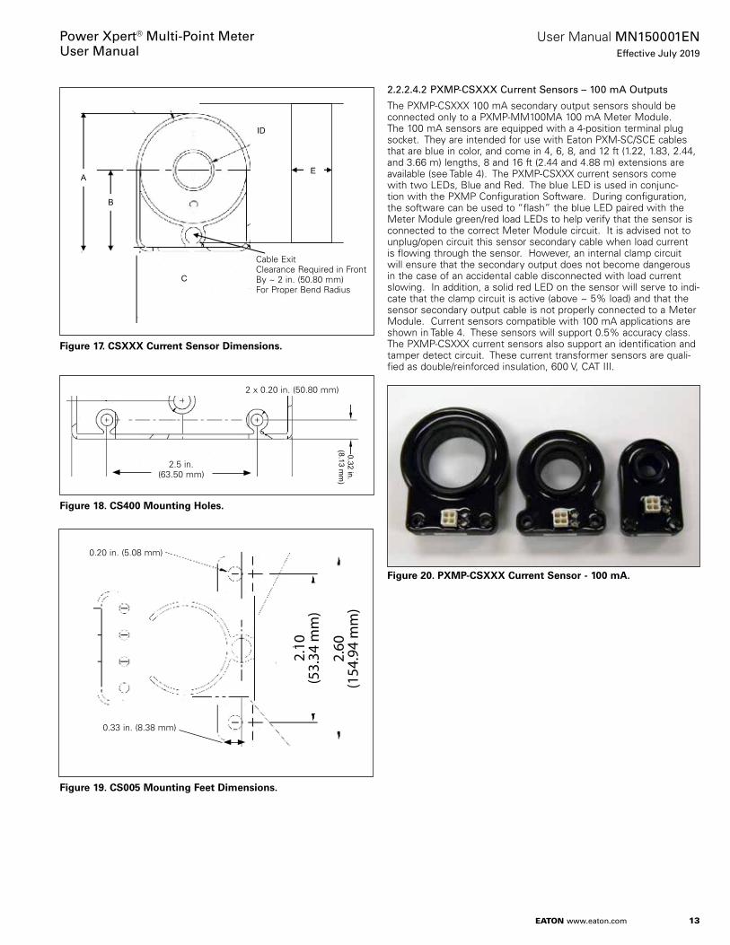
2.2.2.4.2 PXMP-CSXXX Current Sensors – 100 mA Outputs
The PXMP-CSXXX 100 mA secondary output sensors should be connected only to a PXMP-MM100MA 100 mA Meter Module . The 100 mA sensors are equipped with a 4-position terminal plug socket . They are intended for use with Eaton PXM-SC/SCE cables that are blue in color, and come in 4, 6, 8, and 12 ft (1 .22, 1 .83, 2 .44, and 3 .66 m) lengths, 8 and 16 ft (2 .44 and 4 .88 m) extensions are available (see Table 4) . The PXMP-CSXXX current sensors come with two LEDs, Blue and Red . The blue LED is used in conjunc-tion with the PXMP Configuration Software . During configuration, the software can be used to “flash” the blue LED paired with the Meter Module green/red load LEDs to help verify that the sensor is connected to the correct Meter Module circuit . It is advised not to unplug/open circuit this sensor secondary cable when load current is flowing through the sensor . However, an internal clamp circuit will ensure that the secondary output does not become dangerous in the case of an accidental cable disconnected with load current slowing . In addition, a solid red LED on the sensor will serve to indi-cate that the clamp circuit is active (above ~ 5% load) and that the sensor secondary output cable is not properly connected to a Meter Module . Current sensors compatible with 100 mA applications are shown in Table 4 . These sensors will support 0 .5% accuracy class . The PXMP-CSXXX current sensors also support an identification and tamper detect circuit . These current transformer sensors are quali-fied as double/reinforced insulation, 600 V, CAT III .
Figure 20. PXMP-CSXXX Current Sensor - 100 mA.
Figure 17. CSXXX Current Sensor Dimensions.
Figure 18. CS400 Mounting Holes.
Figure 19. CS005 Mounting Feet Dimensions.
B
A
C
ID
E
Cable Exit Clearance Required in Front By ~ 2 in . (50 .80 mm) For Proper Bend Radius
0.32 in.(8.13 m
m)
2 x 0 .20 in . (50 .80 mm)
2 .5 in . (63 .50 mm)
2.10
(53.
34 m
m)
2.60
(154
.94
mm
)
0 .20 in . (5 .08 mm)
0 .33 in . (8 .38 mm)

14
User Manual MN150001ENEffective July 2019
Power Xpert® Multi-Point MeterUser Manual
EATON www.eaton.com
Table 4. 100 mA Sensors Compatible with PXMP-MM100MA Modules.
Catalog Number Description – Solid Core 100 mA Max. Secondary Outputs, 600 V Max. Primary Voltage Rating
Primary Max. ID Turns Ratio
PXMP-CS125 125 A: 0.53 in. (13.4 mm) 1250:1
PXMP-CS250 250 A 1.12 in. (28.5 mm) 2500:1
PXMP-CS400 400 A: 1.74 in. (44.2 mm) 4000:1
Figure 21. PXMP-CS125.
Figure 22. PXMP-CS250.
Figure 23. PXMP-CS400.

15
User Manual MN150001ENEffective July 2019
Power Xpert® Multi-Point MeterUser Manual
EATON www.eaton.com
2.2.2.4.3 PXMP-SC/SCEXX Sensor Cables
The Meter Modules, PXMP-IM Interface Modules, and PXMP-CSXXX Current Sensors are equipped with 2 x 2 receptacles . The PXMP-SC Sensor Cables are designed to connect between the Meter Modules and either a PXMP-CSXX Current Sensor or PXMP-IM Interface Module .
The PXMP Current Sensor Cables are listed in the Table 5 .
Table 5. PXMP-SC/SCEXX Current Sensor Cables.
PXMP Cable Length
PXMP-SC4 PXMP Sensor Cable, 4 ft (1.22 m)
PXMP-SC6 PXMP Sensor Cable, 6 ft (1.83 m)
PXMP-SC8 PXMP Sensor Cable, 8 ft (2.44 m)
PXMP-SC12 PXMP Sensor Cable, 12 ft (3.66 m)
PXMP-SC28-3 PXMP Sensor Cable, 28 ft (8.50 m)
PXMP-SCE8 PXMP Sensor Extension Cable, 8 ft (2.44 m)
PXMP-SCE16 PXMP Sensor Extension Cable, 16 ft (4.88 m)
The PXMP-SC Sensor Cable comes in lengths of 4/6/8/12/28 ft (1 .22/ 1 .83/2 .44/3 .66/8 .50 m) with both ends consisting of male connector plugs . In the case of a system that consists of several panels or switch boards, the PXMP-SCE Sensor Cable Extension can be used to extend to the adjacent structure and allow cables to be discon-nected mid-way to facilitate shipping splits . The PXMP-SCE Sensor Extension Cable comes in 8 and 16 ft (2 .4 and 4 .9 m) lengths with one end as a male plug into the PXMP-CSXXX Current Sensor and the other end a female housing to receive the male plug of the PXMP Sensor Cable .
For accuracy/burden issues, the maximum total length of cable between the PXMPCSXXX Current Sensor and the Meter Module is 28 ft (8 .5 m) .
The sensor cables consist of a 4-position white 2 x 2 plug on each end and four insulated wires in a jacketed cable . Two wires conduct the measured signal proportional to the metered load . The other two wires connect to a sensor identification and tamper detection circuit .
The second two wires also support a locator circuit for use in a special commissioning mode that turns on a blue LED on PXMP-CSXXX Current Sensors or PXMP-IM Interface Modules paired with the red and green LED’s on the Meter Module for the same load . During commissioning or troubleshooting the PXMP Commissioning Software can flash LED's for each metered channel to ring out the Meter Module Input and Sensor pairing to verify that a current sen-sor is paired properly with the specific meter load circuit without having to trace cables or check wire markers . This commissioning mode requires Eaton’s PXMP Configuration Software to activate (refer to Sections 3– Software Overview and 6 - Configuring and Commissioning) .
2.2.2.4.4 PXMP-IM333MV Interface Modules
333mV secondary output current transformer sensors qualified for double/reinforced insulation, 600V, CAT III can be used with the PXMP Mete by using an interposing PXMP-IM333MV Interface Module and a PXMP-SCXX Sensor Cable . This Interface Module pro-vides functionality similar to the PXMP-CS Current Sensors, includ-ing: • Termination and strain relief of current sensor secondary wires (14
AWG [2 .08 mm2]) max . wires;• Conversion to PXMP-SCX cables;• 333 mV CT identification and tamper detection;• Blue LED sensor locator indicator; and• 600 V rated housing – Dimensions 3 .06 x 1 .82 x 0 .77 in . (77 .72 x
46 .23 x 19 .56 mm) .
Sensors must be rated to provide insulation from the metered circuit's conductor . The CT secondary wires should be cut to the desired length, stripped, and terminated at the terminal block on the adapter module . A strain relief strap from the kit should be looped through the interface board and around the current sensor wires pulling them tight to the board as shown . Typically, current sensor wires secondary output wires are color coded Black/White to indi-cate Start/Finish winding relationship in harmony with a load direc-tion indication on the sensor assembly . If the Meter Module Load Power LEDs show inversion then you will have to reverse these connections . The cover should be placed around the assembly and screwed together to secure the housing (see Figure 24) . Choose a PXMP-SCXX Sensor Cable with a length to reach the Meter Module . The Cable and Interface Modules should be routed and positioned so that they do not come in contact with the load cables .
c WARNINGBE SURE THAT LOAD POWER IS OFF WHEN ASSEMBLING THE PXMP-IM INTERFACE MODULES.
Figure 24. PXMP-IM333mV Interface Module.
2.2.3 PXMP Pulse Input Module (PXMP-PIM)
While the Meter Module (see Section 2 .2 .2) meters electrical con-sumption, such as for tenants of an apartment complex, the PXMP Pulse Input Module meters other utilities, such as gas, water, and steam .
The Pulse Input Module requires the customer to have a pulse type output compatible with the PXMP input voltage ratings (24 +/- 20% V), or a switchable intermediate conversion and can capture a pulse rate maximum of 20 Hz square wave . The pulse outputs should be self-compensated for energy measurements .
PXM-SCXX Sensor Cable Connector
Sensor Secondary Lead Wire Entrance
Housing Assembly Screws
Clear Top Housing Cover
Housing Base
Sensor Lead Terminal Block
Strain Relief Strap Holes for Sensor Leads
Blue Locator LED
PXMP-SCXX Sensor Cable
Sensor Secondary Leads

16
User Manual MN150001ENEffective July 2019
Power Xpert® Multi-Point MeterUser Manual
EATON www.eaton.com
Figure 25. PXMP-PIM.
The Pulse Input Module plugs into the Meter Base . It is secured with captive screws that, when tightened, ground the module to the Meter Base and to the earth ground . The Pulse Input Module has terminals for eight digital inputs .
Eight front facing LEDs on the Pulse Input Module flash when digital inputs transition . The LED’s are used to indicate pulse counting is active . The Pulse Input Modules are not intended for application status indication however the LED status does indicate the state of the input
• LED On = Contact closed, current flowing into input;• LED Off = Contact open; no current flowing into input;
Therefore, they can be used for commissioning purposes . Other LEDs indicate COM Status and Health .
The Pulse Input Module has a 2-position, 24 V power supply terminal that must be connected to a local external 24 Vdc power supply ded-icated for PXMP use, do not connect to a CAT III power bus . The same 24 V power supply that is used for the Meter Base assembly can be used for the Pulse Input Modules . This 24 V provides 24 V exciting voltage for the input circuit .
Input of the source pulse must be a dry contact . If contact must be made with a device that sources its own voltage output, then an interposing solid state relay may be placed in the middle to isolate the PXMP from the voltage of the output device .
Each Pulse Input Module has a 2 .2 K ohm input impedance draw-ing approximately 10 mA per closed input . All the commons are tied together internally (refer to Figure 47 - PXMP-PIM Pulse Input Circuitry) .
Metering of ten, 3-phase tenants, for example, would require five Meter Modules to meter ten, 3-phase loads (two tenants per meter module) . If each tenant also had a gas and a water meter with pulse outputs, this would require metering two pulses per tenant (20 total) . Three Pulse Input Modules would be required to meter the 20 pulse inputs (up to eight pulses per module) .
This arrangement would occupy eight slots in the Meter Base, leav-ing two slots free: one could be a PXMP Digital Output Module and one a PXMP Energy Portal Module . The PXMP Digital Output Module is described in Section 2 .2 .4 and the Energy Portal Module in Section 2 .2 .5 .
2.2.4 PXMP Digital Output Module (PXMP-DOM)
The PXMP Digital Output Module provides outputs from the Meter Base logic to external circuit groups . These outputs are used for control or to indicate alarm conditions . A typical installation might be for building automation systems .
The Digital Output Module can be controlled remotely over Modbus, or driven by logic from the Meter Base, based on customer configu-ration . See the Modbus register map for control via Modbus (refer to Section 3 – Software Overview and Appendix B for Modbus Register Map) .
Figure 26. PXMP-DOM.
The Digital Output Module requires an external power source of 24 +/- 20% V . Use a local 24VDC source dedicated for PXMP use, do not connect to a CAT III bus . Each solid state relay can support a maximum load of 80 mA . Each Solid state relay circuit is electrically separate (see Figures 48 and 49 –“Digital Output Module” for wir-ing arrangements) .
The Digital Output Module plugs into the Meter Base with captive screws . These screws, when tightened, ground the module to the Meter Base and to the earth ground . The Digital Output Module has eight front-facing LEDs to display the status of each output . Other LEDs indicate COM Status and Health .
2.2.5 PXMP Energy Portal Module (PXMP-EPM)
The PXMP Energy Portal Module adds sophisticated Web enabled metering capability to the PXMP Meter . A typical application would be WEB enabled Tenant metering in an Apartment complex . The Energy Portal enables each tenant to view graphical comparisons of their day to day and month to month energy usage to help them understand their energy usage patterns . Each Tenant can be provid-ed with unique logon credentials that permit them to see only their power and energy consumption data . The Energy Portal provides a graphically rich HTML5 applet that loads automatically into a stan-dard internet browser when the browser is directed to the Energy Portal IP address .
This module can be ordered as PXMP-EPM-M which supports inter-nal dial up telephone modem with RJ11 connection at the bottom of the module for interface with remote billing software in applications where network connections are not possible or practical .
Once the Energy Portal Module is configured with an IP address, the user interface can be accessed over a Local Area Network (LAN) (see Section 3 – Software Overview) . Metering data can be viewed for each tenant, as well as an aggregated sum of the tenant meters . Power Xpert Multipoint Meters equipped with the Energy Portal module also support the use of the Eaton E-Allocation software . E-Allocation software is available for download from the Eaton WEB site . This application allows tenant contributions to an overall utility bill to be divided among the tenants . E-Allocation can allocate costs from Pulse metering such as Gas and Water as well as Electrical .
The Energy Portal Module comes standard with a front facing Ethernet RJ-45 configuration port and a LAN/WAN RJ-45 Ethernet jack on the bottom end (see Figure 27) .

17
User Manual MN150001ENEffective July 2019
Power Xpert® Multi-Point MeterUser Manual
EATON www.eaton.com
Figure 27. PXMP-EPM and Connections.
The Energy Portal Module plugs into the tenth slot of the Meter Base assembly . It will not function properly in any other slot .
The Energy Portal Module is secured with captive screws that, when tightened, ground the Energy Portal Module to the Meter Base and to the earth ground . For configuration and application details please refer to the “PXMP Energy Portal Web Interface and User Manual” - document number MN150003EN .
.
Health and Status LEDs
ComReset
Local DisplayIP Add.LED
ModemOption LEDs
Local ConfigurationRJ45 Ethernet
LAN/WANLEDs
LAN/WANRJ45EthernetPort
OptionalRJ11TelephoneModem
Com Port 1
Com Port 2
3: PXMP Configuration Software OverviewThe PXMP Configuration Software is a JAVA application provided free of charge by Eaton to support the configuration and commis-sioning of the PXMP Meter . This utility is included on a CD provided with each PXMP Meter Base (PXMP-MB) . The software can also be downloaded from the Eaton Power Xpert Multi-Point Meter Web site . Please refer to the PXMP Configuration Software Manual MN150002EN for details .
For local configuration of a PXMP Meter, the software can be run on a laptop computer equipped with JAVA 1 .7 or higher . For instruc-tions on the use of the PXMP Configuration Software Manual MN150002EN .
To simplify PXMP configuration, a Wizard is provided that guides the operator through a complete configuration process . The software supports both online and offline configuration sessions . To conduct an online session, connect the laptop to the USB port on the Meter Base using a standard USB cable with a Type B USB connector to interface with the meter . Start the software and it will automatically connect to the PXMP Meter . Configuration can also be done over an RS-485 Modbus communications link to either of the PXMP Meter’s Com ports 1 or 2 .
When launched, the PXMP Configuration Software presents the User with a screen that allows the base information for the electrical system to be entered .
Figure 28. Main Screen for Entering the Meter Base Electrical System Information.

18
User Manual MN150001ENEffective July 2019
Power Xpert® Multi-Point MeterUser Manual
EATON www.eaton.com
After the base electrical system information has been entered, the PXMP Configuration Software allows the User to enter the informa-tion for each slot in the Meter Base assembly .
Figure 29. New Configuration Screen - Used to Enter Information for Each Slot in the Meter Base.
For details on the PXMP Configuration Software, please refer to the User Manual supplied with the software (MN150002EN) .
In addition to device configuration, to verify correct device configura-tion and commissioning, the software can also be used in Monitor Mode to view the metering data for each tenant meter .
Figure 30. Software in Monitor Mode to View the Metering Data for Each Tenant Meter.
The PXMP Configuration Software is not intended for use as a permanently installed software solution and does not provide cost allocation functionality . Note also that the USB port is intended for temporary configuration setup, commissioning, and debug purposes only .
Figures 31 and 32 are examples from the E-Allocation Software User Guide manual, publication number MN150004EN,
Figure 31. E-Allocation Software Screen.
Figure 32. E-Allocation Software Screen.

19
User Manual MN150001ENEffective July 2019
Power Xpert® Multi-Point MeterUser Manual
EATON www.eaton.com
3.1 Demand Recording
The PXMP Configuration Software enables the User to create a PXMP configuration consisting of a Main Meter, multiple Sub- meters, and multiple Pulse meters . The maximum number of Sub-meters depends on the number of PXMP Meter Modules installed in the Meter Base . Each Meter Module can be configured for up to six single pole sub-meters, three two-pole meters, or two three-pole meters (or combinations not to exceed six poles) . Each PXMP Pulse Input Module (PXMP-PIM) can be configured for up to eight pulse meters .
The Meter Base assembly is equipped with 256 MB of non-volatile memory for interval by interval demand recording . For the main and each Sub-meter, the Meter Base stores 60 days of interval by interval demand and energy readings for the following parameters:
• W Forward demand (Import)
• W Reverse demand (Export)
• Q1 kVAR demand (Inductive/Motor Load)
• Q2 kVAR demand (Inductive Generator)
• Q3 kVAR demand (Capacitive Generator)
• Q4 kVAR demand (Capacitive Load)
• Q1,Q4 KVA demand (Import)
• Q2,Q3 KVA demand (Export)
• Energy forward
• Energy reverse
For pulse meters, the Meter Base stores the pulse count for each interval .
The PXMP Energy Portal Module (PXMP-EPM) is equipped with 2 GB of non-volatile memory and is capable of storing over 10 years of 15 minute interval by interval demand data .
Figure 33. Basic Components Needed for PXMP Meter Installation.
4: Power Xpert Multi-Point Meter (PXMP Meter) Installation4.1 Introduction
To begin the Power Xpert Multi-Point Meter (PXMP Meter) installa-tion, the following minimum components are typically needed (see Figure 33) .• An Enclosure to house the PXMP Meter System• PXMP Meter Base (PXMP-MB) assembly• At least one PXMP Meter Module (PXMP-MM)• Load Current Sensors and Sensor Cable• Power Supply (24 Vdc Control Power); example PSG60E
In addition, these optional components may be useful:• PXMP Energy Portal Module (PXMP-EPM);• PXMP Pulse Input Module (PXMP-PIM);• PXMP Digital Output Module (PXMP-DOM); and• PXMP External Local Touch Screen Display(PXMP-DISP-6-XV) .
The PXMP Meter and current sensors must be housed in a NEMA or UL enclosure which keeps the internal environment within the PXMP’s environmental specification ranges and provides suitable fire and mechanical protection in the end product installation .

20
User Manual MN150001ENEffective July 2019
Power Xpert® Multi-Point MeterUser Manual
EATON www.eaton.com
Figure 34. PXMP Meter Base Installed in an Enclosure (without Modules Installed).
otee:N If the Meter Base assembly and Energy Portal Module were pur-chased pre-installed in an enclosure or as part of an Eaton Power Distribution Equipment assembly, refer to the documentation supplied with the Meter Base assembly and enclosure for detailed information and instructions .
4.2 Installing a Meter, Pulse Input, Digital Output, and/or Energy Portal Module in the Meter Base Assembly
While it is possible to install Meter, Pulse Input, Digital Output, and Energy Pulse Modules in the Meter Base assembly after it is mount-ed, Eaton recommends installing all modules in the Meter Base assembly before it is installed . This makes the process easier and safer then installing modules after the Meter Base is mounted .
otee:N If installing an Energy Portal Module, it must be installed in Slot 10 .
Before beginning the process of installing a module, place the Meter Base assembly on an appropriate, clean, and well-lit work surface .
1 . Remove the mounting hardware securing the cover plate over the slot in which the module will be installed (see Figure 35) . Remove the cover plate (see Figure 36) .
Figure 35. Removing the Mounting Hardware and Cover Plate.
Figure 36. Cover Plate Removed from Slot 1.
2 . Align the connectors on the module with the receptacle in the open slot . Once properly aligned, press the module into the slot until fully seated . Secure the module in the slot with the captive screws (see Figure 37) .
Figure 37. Module Installed in the Meter Base Assembly.
3 . Repeat the process until all the modules needed for this Meter Base assembly have been installed .
21
User Manual MN150001ENEffective July 2019
Power Xpert® Multi-Point MeterUser Manual
EATON www.eaton.com
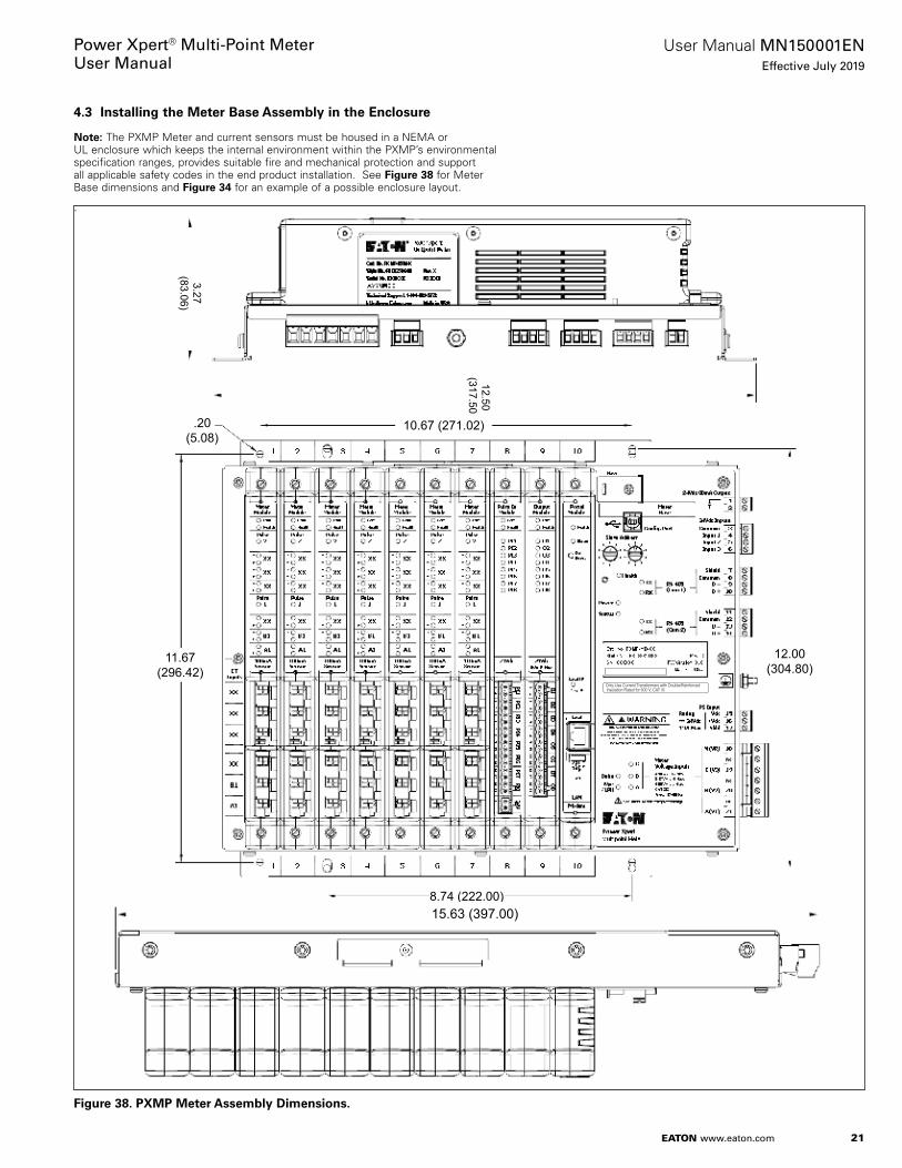
4.3 Installing the Meter Base Assembly in the Enclosure
otee:N The PXMP Meter and current sensors must be housed in a NEMA or UL enclosure which keeps the internal environment within the PXMP’s environmental specification ranges, provides suitable fire and mechanical protection and support all applicable safety codes in the end product installation . See Figure 38 for Meter Base dimensions and Figure 34 for an example of a possible enclosure layout .
.
Figure 38. PXMP Meter Assembly Dimensions.
12.50(317.50)
3.27(83.06)
.20(5.08)
11.67(296.42)
8.74 (222.00)
12.00(304.80)
10.67 (271.02)
Only Use Current Transformers with Double/ReinforcedInsulation Rated for 600 V, CAT III
15.63 (397.00)

22
User Manual MN150001ENEffective July 2019
Power Xpert® Multi-Point MeterUser Manual
EATON www.eaton.com
4.3.1 Before Attempting to Install the PXMP Meter Assembly in the Enclosure
c WARNINGCOMPLETELY READ AND UNDERSTAND THE MATERIAL PRESENTED IN THIS DOCUMENT BEFORE ATTEMPTING INSTALLATION, OPERATION, OR APPLICATION OF THE EQUIPMENT. ONLY QUALIFIED PERSONS SHOULD BE PERMITTED TO PERFORM ANY WORK ASSOCIATED WITH THE EQUIPMENT. ANY WIRING INSTRUCTIONS PRESENTED IN THIS DOCUMENT OR WITH THE PRODUCT MUST BE FOLLOWED PRECISELY. FAILURE TO DO SO COULD CAUSE PERMANENT EQUIPMENT DAMAGE, BODILY INJURY, OR DEATH.
c WARNINGDO NOT ATTEMPT TO INSTALL OR PERFORM MAINTENANCE ON EQUIPMENT WHILE IT IS ENERGIZED. DEATH, SEVERE PERSONAL INJURY, OR SUBSTANTIAL PROPERTY DAMAGE CAN RESULT FROM CONTACT WITH ENERGIZED EQUIPMENT. ALWAYS VERIFY THAT NO VOLTAGE IS PRESENT BEFORE PROCEEDING WITH THE TASK, AND ALWAYS FOLLOW GENERALLY ACCEPTED SAFETY PROCEDURES.
c WARNINGSWITCH MAIN POWER OFF AND WAIT FIVE (5) MINUTES BEFORE MAKING ANY CONNECTION OR DISCONNECTION ON THE DEVICE. DANGER OF EXPLOSION! EATON IS NOT LIABLE FOR THE MISAPPLICATION OR MISINSTALLATION OF ITS PRODUCTS.
Figure 39. Mounting Template for the PXMP Meter Assembly.
.20(5.08)
11.67(296.42)
8.74 (222.00)
12.00(304.80)
10.67 (271.02)
12.60(320.04)
Only Use Current Transformers with Double/ReinforcedInsulation Rated for 600 V, CAT III
CAUTION BEFORE ATTEMPTING TO INSTALL THIS EQUIPMENT IN AN EXISTING OEM ENCLOSURE, MAKE SURE THE ENCLOSURE IS SECURELY MOUNTED AND THAT THE MOUNTING AND ALL EXISTING WIRING MEETS OR EXCEEDS ALL APPLICABLE CODES AND STANDARDS.
1 . Disconnect and lockout all power to the enclosure . Verify that no power is present in the enclosure .
2 . Inspect the enclosure to determine the best mounting location for the PXMP Meter assembly . The mounting location must include:
• Sufficient open area to provide clearance around and in front of the PXMP Meter assembly (see Figure 39 for dimensions) after it is mounted in the enclosure;
• Access to a DIN rail, or an open area to mount the supplied DIN rail, for mounting the 24 Vdc Power Supply;
• Space and paths to route wires to and from the meter; • Access to a protective earth safety ground between the enclosure
and meter base .
3 . Once a preliminary mounting area in the enclosure has been identified, examine the inside of the door of the enclosure for any potential problems/interferences . If none are found, slowly close the enclosure door and observe any movement of components or cables/wiring that may interfere with the PXMP Meter assembly when the door is closed .
4.3.2 Mounting the PXMP Meter Assembly in the Enclosure
1 . Once a suitable mounting location is determined in the enclosure (see Section 4 .3 .1), use the mounting template (see Figure 39) to prepare the mounting surface .

23
User Manual MN150001ENEffective July 2019
Power Xpert® Multi-Point MeterUser Manual
EATON www.eaton.com
CAUTION BEFORE DRILLING, TAKE THE APPROPRIATE STEPS TO ENSURE THAT DRILL SHAVINGS DO NOT FALL ONTO OR INTO ANY COMPONENTS WITHIN THE ENCLOSURE. DRILL SHAVINGS CAN CAUSE SHORT CIRCUITS AND DAMAGE TO THE COMPONENTS WITHIN THE ENCLOSURE.
2 . Align the Meter Base assembly with the holes just drilled in the enclosure . Secure the Meter Base assembly to the enclosure using the mounting hardware supplied .
3 . Connect a protective earth safety ground between the enclosure and the safety ground terminal on the Meter Base assembly .
4.3.3 Installing a 24 Vdc Power Supply in the Enclosure
CAUTION FOR SUFFICIENT CONVECTION COOLING, KEEP A DISTANCE OF 2 IN. (50.8 MM) ABOVE AND BELOW THE DEVICE AS WELL AS A LATERAL DISTANCE OF 0.8 IN. (20.3 MM) TO OTHER UNITS. THE ENCLOSURE OF THE DEVICE CAN BECOME VERY HOT DEPENDING ON THE AMBIENT TEMPERATURE AND LOAD OF THE POWER SUPPLY. IT CAN PRESENT A RISK OF BURNS!
A 24 Vdc power source is required to power the Meter Base assem-bly and any related input or output external circuit groups including those associated with the Meter Base assembly Discrete Input and Output circuits, Pulse Input and Digital Output modules . Use a local 24VDC source dedicated for PXMP use only, do not connect to a CAT III bus . The power rating of the sourcing power supply must be adequate for the total load supplied at the maximum anticipated ambient temperature . This power supply must also be matched to ratings of the application’s mains source and provide isolation from mains .
The following maximum possible 24 Vdc loads need to be consid-ered in a PXMP Meter power system: • 15 W - Meter Base 24 Vdc PS input;• 2 W - Meter Base Digital Output X 1 on max . rated of 80 mA;• 1 W - Meter Base Digital Inputs X 3 contact energized (dry con-
tact closed);• 9 .5 W - PXMP Display• 2 W - Per Pulse Input Module with all eight inputs energized (dry
contact closed);• 20 W worst case for ten cards;
• 15 .4 W – Per Digital Output Module with eight solid state outputs energized;• 154 W worst case for ten cards .
The Eaton PSG family of power supplies is a good match for most PXMP Meter Systems . Those supplies with an E suffix have a 100 – 240 Vac rating which would require a Control Power Transformer (CPT) to step down from higher rated mains source . Those with an F suffix can power directly off of a 480 V Wye mains source .
PSG E suffix, CPT style mains supplies and their output ratings:• PSG60E - 2 .5 amperes (60 W);• PSG120E - 5 amperes (120 W);• PSG240E - 10 amperes (240 W);• PSG480E - 20 amperes (480 W) .
PSG F suffix, 3-phase 400-500 VL:L rated Wye mains supplies and their output ratings:• PSG60F - 2 .5 amperes (60 W);• PSG120F - 5 amperes (120 W);• PSG240F - 10 amperes (240 W);• PSG480F - 20 amperes (480 W) .
otee:N All of the PSG series require de-rating above 50°C (122°F) to 50% load at 70°C (158°F) or below 0°C (32°F) to 80% at -20°C (-4°F) . If any of the 24 Vdc external circuit groups require isolation from the other external circuit groups, then separate power supplies should be used to pro-vide the needed isolation barrier .
For 100-240 V 50/60 Hz mains applications, the Eaton PSG60E 24 Vdc output power supply may be an adequate choice depending on field circuit loads . The PSG60E power supply unit is to be mounted on a 35 mm DIN rail in accordance with EN 60715 . The device should be installed vertically with input terminal blocks on the bot-tom for optimum convection cooling . Each device is delivered ready to install . Follow the mounting instructions supplied with the power supply and review the supply's specification to ensure they meet the application need .
Refer to Figure 40 for the following power supply installation proce-dure .
1 . Tilt the power supply slightly upwards and insert it into the DIN rail .
2 . Push the power supply downwards until it stops .
3 . Firmly press against the bottom front side of the power supply to “lock” it into place .
Figure 40. Installing the PSG60E Power Supply on the DIN Rail in the Enclosure.
4 . Shake the power supply slightly to ensure that it is secured on the DIN rail .
24
User Manual MN150001ENEffective July 2019
Power Xpert® Multi-Point MeterUser Manual
EATON www.eaton.com
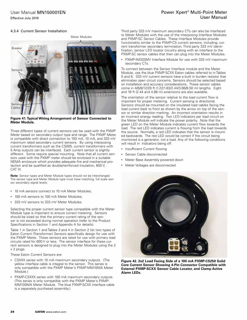
4.3.4 Current Sensor Installation
Figure 41. Typical Wiring Arrangement of Sensor Connected to Meter Module.
Three different types of current sensors can be used with the PXMP Meter based on secondary output type and range . The PXMP Meter is compatible with direct connection to 100 mA, 10 mA, and 333 mV maximum rated secondary current sensors . By using interposing current transformers such as the CS005, current transformers with 5 Amp outputs can be interfaced . Each current sensor is slightly different . Some require special mounting . Note that all current sen-sors used with the PXMP meter should be enclosed in a suitable NEMA enclosure which provides adequate fire and mechanical pro-tection and be qualified as double/reinforced insulation, 600 V, CAT III .
otee:N Sensor types and Meter Module types should not be interchanged . The sensor type and Meter Module type must have matching, full scale sen-sor secondary signal levels:
• 10 mA sensors connect to 10 mA Meter Modules;• 100 mA sensors to 100 mA Meter Modules;• 333 mV sensors to 333 mV Meter Modules .
Selecting the proper current sensor type compatible with the Meter Module type is important to ensure correct metering . Sensors should be sized so that the primary current rating of the sen-sor is not exceeded during normal operation (refer to the Product Specifications in Section 1 and Appendix A for details) .
Table 1 in Section 1 and Tables 3 and 4 in Section 2 list two types of Eaton Current (Transformer) Sensors specifically design for use with the PXMP Meter . These sensors are rated for use with primary load circuits rated for 600 V or less . The sensor interface for these cur-rent sensors is designed to plug into the Meter Modules using the 2 x 2 plugs .
These Eaton Current Sensors are:• CSXXX series with 10 mA maximum secondary outputs . (The
yellow interface cable is integral to the sensor . This series is only compatible with the PXMP Meter’s PXMP-MM10MA Meter Module .)
• PXMP-CSXXX series with 100 mA maximum secondary outputs . (This series is only compatible with the PXMP Meter’s PXMP-MM100MA Meter Module . The blue PXMP-SCXX interface cable is a separately purchased assembly .)
Meter Modules
Breaker
Sensors
Sensor Cables
Third party 333 mV maximum secondary CTs can also be interfaced to Meter Modules with the use of the interposing Interface Modules and PXMP-SC Sensor Cables . These Interface Modules provide functionality similar to the PXMP-CS current sensors, including; cur-rent transformer secondary termination, Third party 333 mV identi-fication, sensor LED locator circuitry along with an interface to the PXMP-SC sensor cables that then can plug into the Meter Modules . • PXMP-IM333MV Interface Module for use with 333 mV maximum
secondary CTs .
To connect between the Sensor Interface module and the Meter Module, use the blue PXMP-SCXX Eaton cables referred to in Tables 5 and 6 . 333 mV current sensors have a built in burden resistor that eliminates open circuit concerns . Sensors should be selected based on installation and accuracy considerations . These sensor cables come in 4/6/8/12/28 ft (1 .22/1 .83/2 .44/3 .66/8 .50 m) lengths . Eight and 16 ft (2 .44 and 4 .88 m) extensions are also available .
The orientation of the sensor relative to the load current flow is important for proper metering . Current sensing is directional . Sensors should be mounted on the insulated load cables facing the load current back to front as shown by the arrow on top of the sen-sor or similar direction marking . An incorrect orientation results in an incorrect energy reading . Two LED indicators per load circuit on the Meter Module will indicate the power polarity . Note that the green LED on the Meter Module indicates current flow towards the load . The red LED indicates current is flowing from the load towards the source . Normally, a red LED indicates that the sensor is mount-ed backwards . The red LED would be correct if the circuit being monitored is a generator, not a load . Any of the following conditions will result in indicators being off:• Insufficient Current flowing• Sensor Cable disconnected• Meter Base Assembly powered down• Meter Voltages are disconnected
Figure 42. 2x2 Load Facing Side of a 100 mA PXMP-CS250 Solid Core Current Sensor Showing 4-Pin Connector Compatible with External PXMP-SCXX Sensor Cable Locator, and Clamp Active Alarm LEDs.

25
User Manual MN150001ENEffective July 2019
Power Xpert® Multi-Point MeterUser Manual
EATON www.eaton.com
Figure 43. 10 mA CS125 Solid Core Current Sensor with Integral 48 in. (1.22 m) Cable.
otee:N As each sensor is installed, Eaton suggests that the Installer mark each sensor cable as to which breaker and pole it is connected . Later in the installation process, this will aid in connecting the sensor cables to the Meter Modules .
4.3.4.1 CS005 Current Transformer
In PXMP Meter applications where a 5 A current transformer is pre-ferred, the CS005 current transformer can be installed to act as an interposing sensor . The CT 5 A secondary should be connected to the primary terminals of the CS005 (see Figure 44) . The secondary 2 x 2 plug should be connected to the 10mA Meter Module 2 x 2 mating receptacle corresponding phase .
For example, if the 5 A CT is monitoring Phase A current, the sec-ondary 2 x 2 plug of the CS005 should be connected to the 2 x 2 receptacle on the 10mA Meter Module .
Example: A1, A2, or A3 if applicable .
The CS005 Current Sensor can also be used in an installation with existing 5 A Secondary Current Transformer . Connect the wire from polarity side of 5 A Secondary Current Transformer to H1(+) terminal of the CS005 Current Sensor and connect the wire from non-polarity side of the 5 A Current Transformer to H2(-) terminal of the CS005 Current Sensor . Eaton recommends using a shorting block between the 5 A Secondary Current Transformers and CS005 Current Sensors .
In some applications, a PXMP-SC-XOVER Crossover Cable is required when using the CS005 in order to measure watts with the proper polarity (see Figure 44) .
Figure 44. Examples of 3-Phase 4-Wire Service Using 5 Amp CTs and CS005 Sensors (Refer to Section 4.4, Figure 63 for more detailed drawing).
Old CS005 Style
New CS005 Style
CS005 with T1/T2 Terminal Markings for PXMP Applications Requires PXMP-SC-XOVER-3 Sensor Cable Crossover Kit
CS005 with H1/H2 Terminal Markings for PXMP Applications

26
User Manual MN150001ENEffective July 2019
Power Xpert® Multi-Point MeterUser Manual
EATON www.eaton.com
WARNING DO NOT DETACH THE CT SECONDARY WIRES FROM THE CS005 UNDER LOAD. THE OPEN CIRCUIT CLAMP DOES NOT PROTECT AGAINST CIRCUIT DISCHARGE WHEN THE CT SECONDARY WIRES FROM THE CS005 ARE DISCONNECTED.
otee:N The polarity markers on the current transformer should match with the markers on the CS005 .
Any standard 5 A secondary current transformer can be used with CS005 for the red line .
For accuracy, a revenue grade CT should be applied . The User will need to configure the current transformer ratio using the PXMP Configuration Software .
Example: If the circuit to be metered is rated for 2000 A, 2000:5 current transformers could be installed on the primary con-ductor . The secondary 5 A circuit would be wired to the CS005 as shown in Figure 44 . The polarity mark side of the 5 A circuit should be connected to the terminal on the CS005 marked "To Line" .
The PXMP Configuration Software can then be used to configure the 2000:5 CT ratio for metering to be correct .
4.3.4.2 Cables and Sensors Supported by the PXMP Meter
The PXMP Meter supports the following types of sensors:• CS005, CS50, CS125, CS200, CS400 – 10 mA maximum second-
ary output sensors;• PXMP-CS125, PXMP-CS250, and PXMP-CS400 – 100 mA maxi-
mum secondary output sensors;• Third party 333 mV secondary maximum rated output .
See Table 6 for sensor to cable information .
Table 6. PXMP Meter Compatible Sensor Cable Overview.
Sensor Cable Color
Cable Length Connector Gender
Catalog Number
10 mA Yellow Blue Blue
4 ft (1.22 m) 8 ft (2.44 m) Ext. 16 ft (4.88 m) Ext.
Male Male/Female Male/Female
Integral PXMP-SCE8-3 PXMP-SCE16-3
100 mA Blue 4 ft (1.22 m) 6 ft (1.83 m) 8 ft (2.44 m) 12 ft (3.66 m) 8 ft (2.44 m) Ext. 16 ft (4.88 m) Ext.28 ft (8.50 m) Ext.
Male/Male Male/Male Male/Male Male/Female Male/FemaleMale/FemaleMale/Female
PXMP-SC4-3 PXMP-SC6-3 PXMP-SC8-3 PXMP-SC12-3 PXMP-SCE8-3PXMP-SCE16-3 PXMP-SCE28-3
PXMP-IM333 MV Blue 4 ft (1.22 m) 6 ft (1.83 m) 8 ft (2.44 m) 12 ft (3.66 m) 8 ft (2.44 m) Ext. 16 ft (4.88 m) Ext.28 ft (8.50 m) Ext.
Male/Male Male/Male Male/Male Male/Female Male/FemaleMale/FemaleMale/Female
PXMP-SC4-3 PXMP-SC6-3 PXMP-SC8-3 PXMP-SC12-3 PXMP-SCE8-3PXMP-SCE16-3PXMP-SCE28-3
PXMP Cable Crossover
Blue 6 in (152.4 mm) Male/Female PXMP-SC-XOVER
otee:N Using the PXMP Configuration Software, each Meter Module can be configured as up to two 3-phase meters, up to three 2-pole meters, and up to six single-pole meters . Combinations of 3-pole, 2-pole, and single-pole meters can be configured on the same Meter Module as long as the total number of poles is six or less . All of the poles for a 2- or 3-pole meter must be on the same Meter Module . Meters cannot be configured to span across multiple modules .
4.3.5 Sensor Installation Procedure
WARNING DO NOT ATTEMPT TO INSTALL OR PERFORM MAINTENANCE ON EQUIPMENT WHILE IT IS ENERGIZED. DEATH, SEVERE PERSONAL INJURY, OR SUBSTANTIAL PROPERTY DAMAGE CAN RESULT FROM CONTACT WITH ENERGIZED EQUIPMENT. ALWAYS VERIFY THAT NO VOLTAGE IS PRESENT BEFORE PROCEEDING WITH THE TASK, AND ALWAYS FOLLOW GENERALLY ACCEPTED SAFETY PROCEDURES. EATON IS NOT LIABLE FOR THE MISAPPLICATION OR MISINSTALLATION OF ITS PRODUCTS.
1 . Ensure that the breaker is de-energized (Lock Out/Tag Out) .
2 . Confirm that the breaker is securely mounted .
3 . Disconnect the load wire to be metered from the breaker .
4 . Slide the current sensor (10 mA, 100 mA, or 333 mV) over the load wire to be metered . Position the sensor over the insulated wire sheath so the current flow is from back to front . For the CSXXX 10 mA current sensors, the flat side is the back to be placed towards the breaker while the cable side faces the load . For the PXMP-CSXXX 100 mA Current Sensors, the side with the white 2 x 2 connector and LEDs should face the load . Also the arrow on top must point to the load . In special reverse feed cases where the breaker cable lugs are fed from the line side instead of feeding the load side, the LED's and 2x2 connector should still be mounted facing away from the breaker . This may result in reverse power flow indication but may be mechanically necessary to mount on reverse fed breakers .
5 . Mount the sensor appropriately for your installation . The PXMP-CSXXX sensors have two 0 .2 in . (5 .08 mm) I . D . holes near the bottom of the housing . For mounting details, refer to Section 2 .
6 . Re-connect the load wire removed from the breaker .
7 . Select the proper cable and length for the application . Include extensions if necessary (refer to Table 6 - PXMP Meter Compatible Sensor Cable Overview) .
CAUTION PLUG ONE END OF THE CABLE INTO THE 2 X 2 RECEPTACLE ON THE PXMP-CSXXX CURRENT SENSOR OR SENSOR INTERFACE MODULE. PLUG THE OPPOSITE END OF THE CABLE INTO THE METER MODULE SOCKET FOR THE CORRECT PHASE TO BE METERED. BE CERTAIN THAT THE METER MODULE TYPE MATCHES THE SENSOR TYPE. USE AN EXTENSION CABLE IF REQUIRED.
otee:N Third party 333mV sensors come with two leads and requries the use of the applicable Interface Module . The Interface Module has a terminal block on one side and a 2 x 2 receptacle on the other side . Plug the sensor cable into Interface Module . Ensure that the secondary wires from the 100ma cur-rent sensor are wired to the terminal block on the interface module before any load current is passed through the sensor to avoid dangerous open circuit voltages .

27
User Manual MN150001ENEffective July 2019
Power Xpert® Multi-Point MeterUser Manual
EATON www.eaton.com
• If using a third party or 333 mV current sensor, then cut the cur-rent sensor leads to the desired length, strip, and terminate the leads to the interface modules terminal block following Black/White (Polarity/Non-Polarity) color coding to preserve polarity to the terminal block of the module .
• A nylon pull strap should be woven through the holes in the inter-face board printed circuit board next to the terminal block and then around the sensor leads . Pull this strap tight for strain relief and cut off the excess strap .
• Add the protective cover on the assembly as per the directions included with the Interface Module and the details in Section 2 .2 .2 .4 .4 - PXMP-IM333mV Interface Modules .
• Configure the Meter Module as required (refer to Section 3 for information regarding PXMP Configuration Software .) .
• Ensure that all safety issues are addressed and then restore power to the breaker .
4.3.6 Installing the Optional PXMP Touch Screen Display
Eaton recommends purchasing an optional 5 .7 in . (144 .78 mm) touch screen display PXMP-DISP-6-XV . This is an Eaton XV-102-H4-57TVRL -10 pre-programmed with PXMP display capa-bilities . A 6 ft (1 .8 m) cable is provided with the display to connect between the Display and the PXMP meter base . The display pro-vides the User with the ability to locally view meter readings to help troubleshoot problems that may arise, and view power system metering data when a computer is not handy or available .
The optional display is for system monitoring purposes only and cannot be used to set-up the PXMP Meter . Set-up of the meter must be done using the PXMP Configuration Software running on the computer . Refer to PXMP Configuration Software manual MN150002EN
Please reference TD150030EN for installation details .

28
User Manual MN150001ENEffective July 2019
Power Xpert® Multi-Point MeterUser Manual
EATON www.eaton.com
4.4 Recommended Wiring Connections
4.4.1 Input/Output (use a local PXMP dedicated external 24VDC source, do not connect to a CAT III bus).
Figure 45. PXMP Meter Base Assembly Digital Input/Output Connections.
Figure 46. PXMP Pulse Input Module Connections.
24V
24V
24V
24V (+)24V (-)
Common
2.2 K Ohm Input Impedance w/Internal Common Connection
ModuleP ul s e I n
P I 1P I 2P I 3P I 4P I 5P I 6P I 7P I 8
C om
H e a lth
PI1PI2
+
-
PI3PI4
PI5PI6
PI7PI8
24V
12
34
56
78
910
1112
1314
1516
24Vdc
Pulse Meter 1 Form A Contact - Dry
Pulse Meter 3 Form A Contact - Dry
Pulse Meter 2 Form A Contact - Dry
Pulse Meter 4 Form A Contact - Dry
Pulse Meter 5 Form A Contact - Dry
Pulse Meter 6 Form A Contact - Dry
Pulse Meter 7 Form A Contact - Dry
Pulse Meter 8 Form A Contact - Dry
Pulse Input Module Power

29
User Manual MN150001ENEffective July 2019
Power Xpert® Multi-Point MeterUser Manual
EATON www.eaton.com
Figure 47. PXMP Pulse Input Circuitry (Note That the 24 Vdc Is Common to All Eight Inputs Per Module).
Figure 48. PXMP Digital Output Module Connections.
16 Pos. Term. Blk. PXMP-PIM Input Circuitry
Odd Term. # = +24VDC
Figure 40 PXMP-PIM Pulse Input circuitry, note that the 24VDC is common to all 8 inputs per module
Figure (2?) in PXMP-PIM TD
Even Term. # = Input
2 Pos. Term. Blk.
Dry contacts
IsolationBarrier
External Source
24VDC
External Circuitry
CommonControl Output 1
Control Output 2
Control Output 3
Control Output 4
Control Output 5Control Output 6Control Output 7
Control Output 8
24V
24V
24V24V
24V24V
24V
24V24V
24V
24V24VO
1O
2O
3O
4O
5O
6O
7O
8
ModuleO ut put
O 1O 2O 3O 4O 5O 6O 7O 8
C om
H e a lth
12
34
56
78
910
1112
1314
1516
24Vdc8 0m A Max
Figure 49. PXMP Digital Output Module Individual Inputs Are Isolated Per Channel.
24Vdc
PXMP-DOM CircuitryExternal Power Source
Load - 80 mA Max
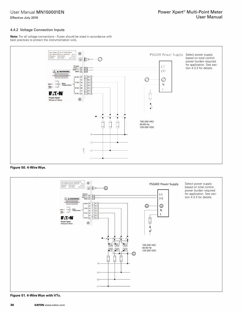
30
User Manual MN150001ENEffective July 2019
Power Xpert® Multi-Point MeterUser Manual
EATON www.eaton.com
4.4.2 Voltage Connection Inputs
otee:N For all voltage connections - Fuses should be sized in accordance with best practices to protect the instrumentation wire .
Figure 50. 4-Wire Wye.
Figure 51. 4-Wire Wye with VTs.
100-240 VAC50-60 Hz125-250 VDC
Select power supply based on total control power burden required for application . See sec-tion 4 .3 .3 for details .
100-240 VAC50-60 Hz125-250 VDC
Select power supply based on total control power burden required for application . See sec-tion 4 .3 .3 for details .

31
User Manual MN150001ENEffective July 2019
Power Xpert® Multi-Point MeterUser Manual
EATON www.eaton.com
Figure 52. 3-Wire Delta.
Figure 53. 3-Wire Delta with VTs.
Select power supply based on total control power burden required for application . See sec-tion 4 .3 .3 for details .
Select power supply based on total control power burden required for application . See sec-tion 4 .3 .3 for details .

32
User Manual MN150001ENEffective July 2019
Power Xpert® Multi-Point MeterUser Manual
EATON www.eaton.com
Figure 54. 3-Wire Delta (No “N”).
Figure 55. Single-Phase 3-Wire 120/240.
100-240 VAC50-60 Hz125-250 VDC
100-240 VAC50-60 Hz125-250 VDC

33
User Manual MN150001ENEffective July 2019
Power Xpert® Multi-Point MeterUser Manual
EATON www.eaton.com
4.4.3 Current Sensor Connections
Figure 56. 3-Phase 4-Wire Service.
Figure 57. 3-Phase 4-Wire Service (Ten 1-Phase 1-Pole).
Va Vb Vc Vn
Sensor Type and Phasing must matchMeter Module!100mA Sensors to 100 mA Meter Module10mA Sensors to 10 mA Meter Module333mV Sensors to 333 mV Meter Module
Phase A Sensors Connect to A1 or A2Phase B Sensors to Connect B1 or B2Phase C Sensors to Connect C1 or C2
C
A
N
B
A1B1C1A2B2C2
A1B1C1A2B2C2
Load #4CB
A
CB
A
CB
A
CB
A
C
A
N
B Load #3
C
A
N
B Load #2
C
A
N
B Load #1
Va Vb Vc Vn
Sensor Type and Phasing must matchMeter Module!100mA Sensors to 100 mA Meter Module10mA Sensors to 10 mA Meter Module333mV Sensors to 333 mV Meter Module
Phase A Sensors Connect to A1 or A2Phase B Sensors to Connect B1 or B2Phase C Sensors to Connect C1 or C2
N
A1B1C1A2
A1B1C1A2
Load #10A
C
B
A
A
N Load #9C
N Load #8B
N Load #7A
A
C
B
A
N Load #4A
N Load #3C
N Load #2B
N Load #1A
B2C2
C
B
N Load #6C
N Load #5B

34
User Manual MN150001ENEffective July 2019
Power Xpert® Multi-Point MeterUser Manual
EATON www.eaton.com
Figure 58. Network 120/208 3-Wire Apartment Service.
Figure 59. 3-Phase 3-Wire Delta Service.
Va Vb Vc Vn
Sensor Type and Phasing must matchMeter Module!100mA Sensors to 100 mA Meter Module10mA Sensors to 10 mA Meter Module333mV Sensors to 333 mV Meter Module
Phase A Sensors Connect to A1 or A2Phase B Sensors to Connect B1 or B2Phase C Sensors to Connect C1 or C2
C
C
A
A
N
N
B
B
N
C
C
A
A
N
N
B
B
N
A1B1C1A2B2C2
A1B1C1A2B2C2
Apt #4
Apt #6
Apt #5
Apt #1
Apt #3
Apt #2
C
B
A
C
CB
A
C
B
A
C
B
A
Va Vb Vc
Sensor Type and Phasing must matchMeter Module!100mA Sensors to 100 mA Meter Module10mA Sensors to 10 mA Meter Module333mV Sensors to 333 mV Meter Module
Phase A Sensors Connect to A1 or A2Phase B Sensors to Connect B1 or B2Phase C Sensors to Connect C1 or C2
C
AB
A1B1C1A2B2C2
A1B1C1A2B2C2
Motor #4C
BA
CB
A
CB
A
CB
A
C
AB
C
AB
C
AB
Motor #3
Motor #2
Motor #1
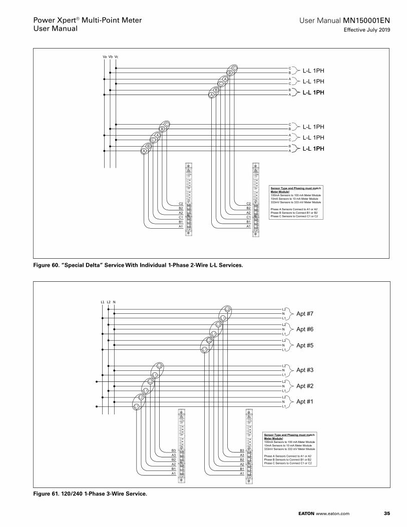
35
User Manual MN150001ENEffective July 2019
Power Xpert® Multi-Point MeterUser Manual
EATON www.eaton.com
Figure 60. “Special Delta” Service With Individual 1-Phase 2-Wire L-L Services.
Figure 61. 120/240 1-Phase 3-Wire Service.
Va Vb Vc
Sensor Type and Phasing must matchMeter Module!100mA Sensors to 100 mA Meter Module10mA Sensors to 10 mA Meter Module333mV Sensors to 333 mV Meter Module
Phase A Sensors Connect to A1 or A2Phase B Sensors to Connect B1 or B2Phase C Sensors to Connect C1 or C2
C
A
B
A1B1C1A2B2C2
A1B1C1A2B2C2
L-L 1PHCB
AC
BA
C
AB
L-L 1PH
L-L 1PHL-L 1PH
C
A
B L-L 1PHCB
AC
BA
C
AB
L-L 1PH
L-L 1PHL-L 1PH
L1 L2 N
Sensor Type and Phasing must matchMeter Module!100mA Sensors to 100 mA Meter Module10mA Sensors to 10 mA Meter Module333mV Sensors to 333 mV Meter Module
Phase A Sensors Connect to A1 or A2Phase B Sensors to Connect B1 or B2Phase C Sensors to Connect C1 or C2
L2
L1
L2
L1
N
N
L1
L2
N
L2
L1
L2
L1
N
N
L1
L2
N
A1B1A2B2A3B3
Apt #5
Apt #7
Apt #6
Apt #1
Apt #3
Apt #2
L2
L1
C
L2
L1
L2
L1
L2
L1
L2
L1
L2
L1
A1B1A2B2A3B3
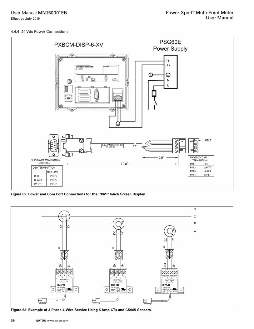
36
User Manual MN150001ENEffective July 2019
Power Xpert® Multi-Point MeterUser Manual
EATON www.eaton.com
4.4.4 24 Vdc Power Connections
Figure 62. Power and Com Port Connections for the PXMP Touch Screen Display.
Figure 63. Example of 3-Phase 4-Wire Service Using 5 Amp CTs and CS005 Sensors.
PXBCM-DISP-6-XV PSG60EPower Supply
(-)(+)
NL
Eaton P/N 67A2124HXXYY-MM-DD
2.0"
PIN 2PIN 3
REDWHITEBLACK
PIN 1
PIN 4 BARE
72.0"
PIN 1
PHOENIX CONN.TERMINATION
PIN 3PIN 5PIN 7
REDBLACKWHITE
DB9 SHELL
DB9 TERMINATIONH12 (XV)
SHIELD WIRE TERMINATED to
A
B
C
N
H1
H1
H1
H2H2
H2
X1
X2
H1
H1
H1
X1
X2
X1
X2

37
User Manual MN150001ENEffective July 2019
Power Xpert® Multi-Point MeterUser Manual
EATON www.eaton.com
5: Serial Communications Setup5.1 PXMP Meter Communication
The PXMP Meter provides two Com ports with RS485 serial inter-faces supporting Slave Modbus RTU protocol . The Modbus Map of registers can be found in Appendix B .
5.1.1 RS485 Com 1 and Com 2
Com 1 and Com 2 provide two RS-485 serial communication ports supporting Modbus Slave RTU protocol .
Both RS-485 Modbus slave ports can be addressed from 1 to 99 using two rotary switches on the face of the PXMP Meter Base (PXMP-MB) assembly . The Modbus slave ID selected with the rota-ry switches applies to both Modbus Slave ports . The default com-munication settings are 115 .2 K baud, no parity, one stop bit .
The PXMP Configuration Software can be used to adjust these com-munication settings . Refer to Section 3 - Software Overview and the PXMP Configuration Software User Manual (MN150002EN) for more information about how to use the PXMP Configuration Software .
The slave port connectors include a Data+ (D+), Data- (D-), Common, and Shield terminals . Eaton recommends the use of RS-485 wiring that includes a twisted pair for data, a conductor for common, and a separate shield for optimal signal integrity and noise immunity . There are some variations on RS-485 wiring . If the Meter Base assembly is to be inserted into a daisy-chain that does not have an independent common and shield, the common and shield terminals can be jumpered externally on the terminal block so that the RS485 common will connect via the shield between nodes . Figure 65 shows the detail of a two Data wire RS485 connection with separate common and shield .
Figure 64. PXMP Meter Base Serial Coms.
Optional PXMP-EPM for Ethernet LAN/WAN Communications
USB Configuration Port
Com Port 1
Com Port 2
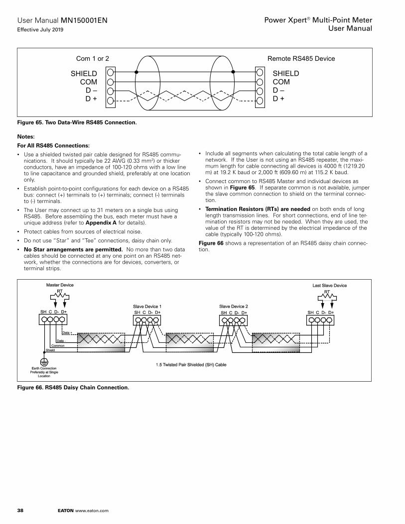
38
User Manual MN150001ENEffective July 2019
Power Xpert® Multi-Point MeterUser Manual
EATON www.eaton.com
Figure 65. Two Data-Wire RS485 Connection.
Notese:
For All RS485 Connectionse:
• Use a shielded twisted pair cable designed for RS485 commu-nications . It should typically be 22 AWG (0 .33 mm2) or thicker conductors, have an impedance of 100-120 ohms with a low line to line capacitance and grounded shield, preferably at one location only .
• Establish point-to-point configurations for each device on a RS485 bus: connect (+) terminals to (+) terminals; connect (-) terminals to (-) terminals .
• The User may connect up to 31 meters on a single bus using RS485 . Before assembling the bus, each meter must have a unique address (refer to Appendix A for details) .
• Protect cables from sources of electrical noise .• Do not use “Star” and “Tee” connections, daisy chain only .• No Star arrangements are permitted. No more than two data
cables should be connected at any one point on an RS485 net-work, whether the connections are for devices, converters, or terminal strips .
Figure 66. RS485 Daisy Chain Connection.
Com 1 or 2 Remote RS485 Device
SHIELD COM
D – D+
SHIELD COM
D – D +
SHIELD COM D – D +
• Include all segments when calculating the total cable length of a network . If the User is not using an RS485 repeater, the maxi-mum length for cable connecting all devices is 4000 ft (1219 .20 m) at 19 .2 K baud or 2,000 ft (609 .60 m) at 115 .2 K baud .
• Connect common to RS485 Master and individual devices as shown in Figure 65 . If separate common is not available, jumper the slave common connection to shield on the terminal connec-tion .
• Termination Resistors (RTs) are needed on both ends of long length transmission lines . For short connections, end of line ter-mination resistors may not be needed . When they are used, the value of the RT is determined by the electrical impedance of the cable (typically 100-120 ohms) .
Figure 66 shows a representation of an RS485 daisy chain connec-tion .

39
User Manual MN150001ENEffective July 2019
Power Xpert® Multi-Point MeterUser Manual
EATON www.eaton.com
5.2 PXMP Meter Communication Information
The PXMP Meter does not include an integral user interface on the front face of the meter for accessing metering data . The RS485 Com ports connection on the right side of the meter shown in Figure 64 can be used for accessing this data with an external device such as the PXMP Display . The configuration software can also use these Com ports or the local USB configuration port .
5.2.1 Meter Connection
The RS485 cable attaches to the Com port terminals Shield/Common/Data-/Data+ as shown in Figure 65 .
5.2.2 Initiating Communications with PXMP Meter
Configure the Modbus master device to match the communications settings for the PXMP Meter .
otee:N Factory default RS-485 communications are:
• Baud Rate: 115 .2 K baud;• Parity: None; and• Stop Bits: One .
Set the slave ID rotary switches (see Figure 10) to a slave ID between 1 and 99 . Take care that the slave ID selected does not conflict with any other slave on the RS-485 daisy chain .
Connect to the PXMP Meter RS-485 communications port in accor-dance with the instructions in this section .
The Modbus master should now be able to communicate with the PXMP Meter at the slave ID configured by the rotary switches . Successful communications can be observed using the TX and RX LEDs on the PXMP Meter . If the PXMP Meter receives and under-stands a valid request from a Modbus master, the RX LED will blink followed by the TX LED . If the RX LED blinks but there is no TX LED activity, check the communications settings to be sure that the mas-ter and slave match .
6: Configuring and CommissioningOnce the PXMP Meter assembly has been installed in a suitable NEMA rated enclosure, 24 Vdc power supplied, the sensors have been installed and connected to the Meter Modules (PXMP-MMs), and all wiring and communications connections have been made, the PXMP Meter can be configured and commissioned via the PXMP Configuration Software running on a PC or laptop computer .
Once the PXMP Meter has been configured and commissioned, data from the meter can be read via the PXMP Meter Configuration Software or the optional PXMP Display .
7: Maintenance and Cleaning InstructionsThe PXMP Meter is maintenance free once properly commissioned . There are no User serviceable components or features .
Cleaning of the PXMP housing should only be done with power and mains disconnected . A clean dry rag can be used to remove dust . No liquids should be used .
8: Reading Meter Settings and Data Via the Optional PXMP DisplayThe Power Xpert Multi-Point Touch Screen Display (PXMP Display) is an essential tool that provides visibility to configuration, meter, and diagnostic data . With access to the entire Modbus map of the meter, the PXMP Display not only shows data but also becomes an invaluable tool for verification and validation of the entire PXMP Meter . The intent is to display all system meter data and sub-meter data without support for trends, profiles, resets, or other controls . The display can also be a window into the status of inputs and out-puts as well as their associated counters .
The PXMP Display has no setup capabilities . What is shown on the display is the information the display is reading from the PXMP Meter . The display is a totally flexible viewer that can adapt to any configuration programmed into the meters by the Installer/User via the PXMP Configuration Software (see MN150002EN) .
When functioning as the “System” meter, the PXMP Display will show either what is being received from a meter that is monitoring the entire system or an internal summation of all the meters within the system as if they were all one meter . This depends on how the meter is set up during the configuration process .
Please reference PXMP-DISP-6-XV Feature Walkthrough (IB150022EN) for additional details .

40
User Manual MN150001ENEffective July 2019
Power Xpert® Multi-Point MeterUser Manual
EATON www.eaton.com
Appendix A: SpecificationsA.1 Environmental
The PXMP Meter and current sensors must be housed in a NEMA or UL enclosure that keeps the internal environment within the PXMP’s environmental specification ranges and provides suit-able fire and mechanical protection in the end product installation . Temperature Range: -20 to +70°C (-4 to +158°F)• Storage Temperature Range: -40 - 85°C • Humidity: 5-95% Non-condensing Environment• Pollution Degree: II• Elevation: 0 to 9,843 ft (0 to 3000 m)• Housing: IP20
CE Mark
EMC EN61326
Emissions Conducted and Radiated:• FCC part 15 class B• CISPR 11 class B
Electromagnetic Immunity
Standard Description Level
EN61000-4-2 ESD 3
EN61000-4-3 RF Radiated 3
EN61000-4-4 Electrical Fast Transient 3
EN61000-4-5 Surge 3*
EN61000-4-6 RF Conducted 3
EN61000-4-11 Volt Sag/Swell/Variation
* 24VDC PXMP inputs are for a local bus which is surge level 2. PXG60E AC mains connection will support level 3.
Product Safety:• IEC/EN61010-1• UL61010-1 File E185559• CNL evaluation to CAN/C22 .2 No 1010 .1 .92
Accuracy:• ANSI C12 .20 - Accuracy Class 0 .5% with Either CSXXX or PXMP-
CSXXX sensors• Measurement Canada Approval Pending
A.2 External Circuit Group Specifications
PXMP-MB (-AB) Meter Base
Discrete Output:• Qty . 1 – Solid State Relay Form A NO Bidirectional FET• Polarity of external source is not important• Isolation Circuit to ground 2 kV/1 min .• Maximum external source voltage 28 Vdc• Line to Line TVS clamp across switching element at 32 Vdc• Solid State Relay On resistance 35 ohms maximum• Maximum load current 80 mA• Minimum pulse width 20 milliseconds• Fixed 25 milliseconds for Pulse Initiator function• Maximum pulse rate 25 Hz• Wiring to 2-position removable terminal plug
• 12-18 AWG (3 .31-0 .82 mm2), wire ferrules recommended
• T1 (Polarity not important)
• T2 (Polarity not important)
Discrete Inputs:• Qty . 3, common circuits Inputs1-3• Group isolation 2 kV
• No Input to Input circuit isolation
• All inputs per module share a common external 24 V (+/-10%) supply• 24 V externally sourced between common and inputs
• Design to interface with external dry contact
• Input impedance ~ 2 .2 Kohm
• Input current draw ~ 10 mA per input
• Minimum pulse width 10 milliseconds• Maximum pulse rate 20 Hz• Wiring to 4-position removable terminal plug
• 12-18 AWG (3 .31-0 .82 mm2), wire ferrules recommended
• T3- Common (connect ext . 24 common here)
• T4 – Input 1 (dry contact to 24 V hot)
• T5 – Input 2 (dry contact to 24 V hot)
• T6 – Input 3 (dry contact to 24 V hot)
Com 1 and Com2 RS485 Serial Ports:• No D+/D- biasing, reliance on fail safe driver and biasing at Master• Baud rate configurable between 9600 – 115 K baud (default)• Use cable designed for RS485 communications
• Low L:L capacitance
• Impedance of ~ 100-120 ohms
• Shield – Mylar for high freq ., Braid for low freq .
• Separate common and shield for best noise immunity
• Maximum cable length is 4000 ft (1,219 .2 m) with 32 nodes at 19 .2 K baud increased data rates will reduce maximum cable distance
• 2000 ft (609 .6 m)with 32 total nodes at 115 .2 K baud
• Isolation 300 V to ground due to TVS diode clamps• Modbus RTU slave protocol, address defined by rotary switch• Green Rx and Red Tx LEDs per channel• Data + > Data – during idle marked, logic 1 state
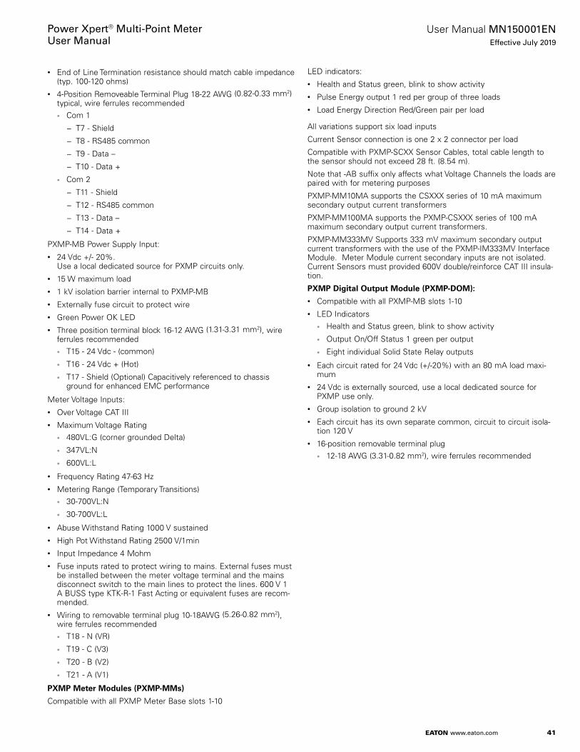
41
User Manual MN150001ENEffective July 2019
Power Xpert® Multi-Point MeterUser Manual
EATON www.eaton.com
• End of Line Termination resistance should match cable impedance (typ . 100-120 ohms)
• 4-Position Removeable Terminal Plug 18-22 AWG (0 .82-0 .33 mm2) typical, wire ferrules recommended• Com 1
− T7 - Shield
− T8 - RS485 common
− T9 - Data –
− T10 - Data +
• Com 2
− T11 - Shield
− T12 - RS485 common
− T13 - Data –
− T14 - Data +
PXMP-MB Power Supply Input:• 24 Vdc +/- 20% .
Use a local dedicated source for PXMP circuits only .• 15 W maximum load• 1 kV isolation barrier internal to PXMP-MB• Externally fuse circuit to protect wire• Green Power OK LED• Three position terminal block 16-12 AWG (1 .31-3 .31 mm2), wire
ferrules recommended• T15 - 24 Vdc - (common)
• T16 - 24 Vdc + (Hot)
• T17 - Shield (Optional) Capacitively referenced to chassis ground for enhanced EMC performance
Meter Voltage Inputs:• Over Voltage CAT III• Maximum Voltage Rating
• 480VL:G (corner grounded Delta)
• 347VL:N
• 600VL:L
• Frequency Rating 47-63 Hz• Metering Range (Temporary Transitions)
• 30-700VL:N
• 30-700VL:L
• Abuse Withstand Rating 1000 V sustained• High Pot Withstand Rating 2500 V/1min• Input Impedance 4 Mohm• Fuse inputs rated to protect wiring to mains . External fuses must
be installed between the meter voltage terminal and the mains disconnect switch to the main lines to protect the lines . 600 V 1 A BUSS type KTK-R-1 Fast Acting or equivalent fuses are recom-mended .
• Wiring to removable terminal plug 10-18AWG (5 .26-0 .82 mm2), wire ferrules recommended• T18 - N (VR)
• T19 - C (V3)
• T20 - B (V2)
• T21 - A (V1)
PXMP Meter Modules (PXMP-MMs)
Compatible with all PXMP Meter Base slots 1-10
LED indicators:• Health and Status green, blink to show activity• Pulse Energy output 1 red per group of three loads• Load Energy Direction Red/Green pair per load
All variations support six load inputs
Current Sensor connection is one 2 x 2 connector per load
Compatible with PXMP-SCXX Sensor Cables, total cable length to the sensor should not exceed 28 ft . (8 .54 m) .
Note that -AB suffix only affects what Voltage Channels the loads are paired with for metering purposes
PXMP-MM10MA supports the CSXXX series of 10 mA maximum secondary output current transformers
PXMP-MM100MA supports the PXMP-CSXXX series of 100 mA maximum secondary output current transformers .
PXMP-MM333MV Supports 333 mV maximum secondary output current transformers with the use of the PXMP-IM333MV Interface Module . Meter Module current secondary inputs are not isolated . Current Sensors must provided 600V double/reinforce CAT III insula-tion .
PXMP Digital Output Module (PXMP-DOM)e:
• Compatible with all PXMP-MB slots 1-10• LED Indicators
• Health and Status green, blink to show activity
• Output On/Off Status 1 green per output
• Eight individual Solid State Relay outputs
• Each circuit rated for 24 Vdc (+/-20%) with an 80 mA load maxi-mum
• 24 Vdc is externally sourced, use a local dedicated source for PXMP use only .
• Group isolation to ground 2 kV• Each circuit has its own separate common, circuit to circuit isola-
tion 120 V• 16-position removable terminal plug
• 12-18 AWG (3 .31-0 .82 mm2), wire ferrules recommended

42
User Manual MN150001ENEffective July 2019
Power Xpert® Multi-Point MeterUser Manual
EATON www.eaton.com
PXMP Pulse Input Modules (PXMP-PIMs)e:
• Compatible with all PXMP-MB slots 1-10• LED Indicators
• Health and Status green, blink to show activity
• Input On/Off Status 1 green per Pulse Input
• Eight Pulse Inputs to external dry contacts• Maximum pulse rate is 20 Hz• Minimum pulse width is 20 milliseconds• External circuit groups rated for 24 Vdc (+/-20%)
• All circuits share the same electrical common
• Use a dedicated local source for PXMP circuits only
• External supply connects to the module with a two-position removable terminal plug
• The supply is internally fanned out to all circuits• Group isolation limited to 300 V to ground due to TVS diode clamp• Input impedance ~2 .2 K causing a 10 mA load per input when
energized• External circuit groups connect with a 16-position removable ter-
minal plug• Terminals support 12-18 AWG (3 .31-0 .82 mm2), wire ferrules
recommended
PXMP Energy Portal Module (PXMP-EPM)e:
• Only functionally compatible with PXMP-MB slot 10• LED Indicators
• Top Health and Status green, blink to show activity
• Com . Reset button - reset to defaults
• Local IP 192/10
• RJ45 Front Facing Ethernet Configuration Port LEDs
− Link (Tx/Rx blink)
− 10/100 speed
• LED 4-stack for Bottom LAN/WAN Ethernet port• Link (Tx/Rx blink)
• 10/100 speed
• DHCP/Fixed
• TX active
• Config . Ethernet RJ45 Cat 5 STP/UTP• 10 base T/100 base Tx
• Auto Cross-over capability supported
• Java web browser interface
• Bottom Facing LAN/WAN Ethernet Port• RJ45 Cat5 STP/UTP 10 base T/100 base Tx
• STP required for full electromagnetic immunity
• Auto Cross-over capability supported
• Supports Modbus TCP and Java web browser interface
• Bottom facing Telephone Modem interface• Modem type V92/56 K Baud
• RJ11 field interface

43
User Manual MN150001ENEffective July 2019
Power Xpert® Multi-Point MeterUser Manual
EATON www.eaton.com
Appendix A: Specifications (Cont.)
Table A1. Power Xpert Multi-point Meter System – Hardware Specifications.
Components Field Circuit
PowerSource
RatedVoltage
RatedCurrent
CircuitImpedance
Isolation Note 1 Note 2
PXMP-MB PXMP-MB-AB
Digital Output External* 24 +/- 20% 2 0.080 A Max. 35 Ohms Max. 2.0 kV
Digital Input External* 24 +/-20% 2 0.01 A 2.22 K 2.0 kV Opto Drops Supply by 2 V
Group are electrically common
Com 1 RS485 Internal 5 V 2 50-60 Ohms 300 V TVS Diode Clamped to PE
Com 2 RS485 Internal 5 V 2 50-60 Ohms 300 V TVS Diode Clamped to PE
Power Supply Input
External* 24 +/- 20% 2 0.7 A Max. N. A. 1.0 kV Installation Class II Input
15W Max
Voltage Inputs A (V1)/ B (V2)/ C (V3)/ N (VR)
Ext. Mains 480 V L:G 1 0.12 mA 4.M Ohm NA Installation Class III High Pot 2500 V/1 Min
347 V L:N 1 0.09mA 4.M Ohm NA Installation Class III High Pot 2500 V/1 Min
600 V L:L 1 0.09mA 4.M Ohm NA Installation Class III High Pot 2500 V/1 Min
PXMP-MM100MA CT Secondary External N.A. 100 mA 14.6 Ohms NA 20% Over-range See sensor for Primary isolation
PXMP-MM10MA CT Secondary External N.A. 10 mA 67 Ohms NA 20% Over-range See sensor for Primary isolation
PXMP-MM333MV CT Secondary External 0.333 V 1 N.A. 50,000 Ohms NA 20% Over-range See sensor for Primary isolation
PXMP-DOM Digital Output External 24 +/- 20% 2 0.080 A Max. 10 Ohms Max. 2 kV Group 120V isolation circuit to circuit
Isolation dependent on external source
PXMP-PIM Pulse Input External 24+/- 20% 2 0.01 A 2.22 K ohms 300 V to Ground
TVS Diode Clamped to PE.Group Isolated, All Circuits Common to 24 V Ext. Source.
Note opto creates 2.2 V drop sourced by 2.2 Kohms. Isolation dependent on external source
PXMP-EPM Ethernet 100 Bt Internal NA NA 1 kV
POT Modem Internal NA NA1 AC RMS. 2 DC
* Use a local dedicated 24VDC source for PXMP circuits, do not connect to a CAT III bus.
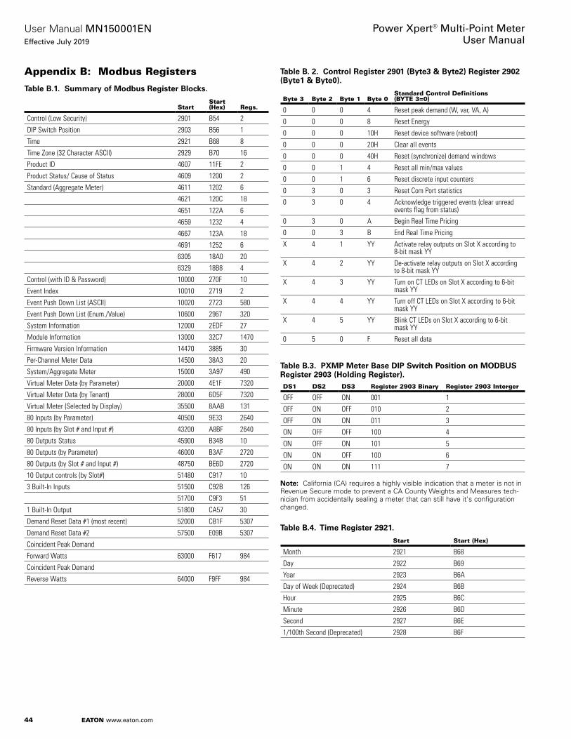
44
User Manual MN150001ENEffective July 2019
Power Xpert® Multi-Point MeterUser Manual
EATON www.eaton.com
Appendix B: Modbus Registers
Table B.1. Summary of Modbus Register Blocks.
StartStart (Hex) Regs.
Control (Low Security) 2901 B54 2
DIP Switch Position 2903 B56 1
Time 2921 B68 8
Time Zone (32 Character ASCII) 2929 B70 16
Product ID 4607 11FE 2
Product Status/ Cause of Status 4609 1200 2
Standard (Aggregate Meter) 4611 1202 6
4621 120C 18
4651 122A 6
4659 1232 4
4667 123A 18
4691 1252 6
6305 18A0 20
6329 18B8 4
Control (with ID & Password) 10000 270F 10
Event Index 10010 2719 2
Event Push Down List (ASCII) 10020 2723 580
Event Push Down List (Enum./Value) 10600 2967 320
System Information 12000 2EDF 27
Module Information 13000 32C7 1470
Firmware Version Information 14470 3885 30
Per-Channel Meter Data 14500 38A3 20
System/Aggregate Meter 15000 3A97 490
Virtual Meter Data (by Parameter) 20000 4E1F 7320
Virtual Meter Data (by Tenant) 28000 6D5F 7320
Virtual Meter (Selected by Display) 35500 8AAB 131
80 Inputs (by Parameter) 40500 9E33 2640
80 Inputs (by Slot # and Input #) 43200 A8BF 2640
80 Outputs Status 45900 B34B 10
80 Outputs (by Parameter) 46000 B3AF 2720
80 Outputs (by Slot # and Input #) 48750 BE6D 2720
10 Output controls (by Slot#) 51480 C917 10
3 Built-In Inputs 51500 C92B 126
51700 C9F3 51
1 Built-In Output 51800 CA57 30
Demand Reset Data #1 (most recent) 52000 CB1F 5307
Demand Reset Data #2 57500 E09B 5307
Coincident Peak Demand
Forward Watts 63000 F617 984
Coincident Peak Demand
Reverse Watts 64000 F9FF 984
Table B. 2. Control Register 2901 (Byte3 & Byte2) Register 2902 (Byte1 & Byte0).
Byte 3 Byte 2 Byte 1 Byte 0Standard Control Definitions (BYTE 3=0)
0 0 0 4 Reset peak demand (W, var, VA, A)
0 0 0 8 Reset Energy
0 0 0 10H Reset device software (reboot)
0 0 0 20H Clear all events
0 0 0 40H Reset (synchronize) demand windows
0 0 1 4 Reset all min/max values
0 0 1 6 Reset discrete input counters
0 3 0 3 Reset Com Port statistics
0 3 0 4 Acknowledge triggered events (clear unread events flag from status)
0 3 0 A Begin Real Time Pricing
0 0 3 B End Real Time Pricing
X 4 1 YY Activate relay outputs on Slot X according to 8-bit mask YY
X 4 2 YY De-activate relay outputs on Slot X according to 8-bit mask YY
X 4 3 YY Turn on CT LEDs on Slot X according to 6-bit mask YY
X 4 4 YY Turn off CT LEDs on Slot X according to 6-bit mask YY
X 4 5 YY Blink CT LEDs on Slot X according to 6-bit mask YY
0 5 0 F Reset all data
Table B.3. PXMP Meter Base DIP Switch Position on MODBUS Register 2903 (Holding Register).DS1 DS2 DS3 Register 2903 Binary Register 2903 Interger
OFF OFF ON 001 1
OFF ON OFF 010 2
OFF ON ON 011 3
ON OFF OFF 100 4
ON OFF ON 101 5
ON ON OFF 100 6
ON ON ON 111 7
otee:N California (CA) requires a highly visible indication that a meter is not in Revenue Secure mode to prevent a CA County Weights and Measures tech-nician from accidentally sealing a meter that can still have it's configuration changed .
Table B.4. Time Register 2921.
Start Start (Hex)
Month 2921 B68
Day 2922 B69
Year 2923 B6A
Day of Week (Deprecated) 2924 B6B
Hour 2925 B6C
Minute 2926 B6D
Second 2927 B6E
1/100th Second (Deprecated) 2928 B6F

45
User Manual MN150001ENEffective July 2019
Power Xpert® Multi-Point MeterUser Manual
EATON www.eaton.com
Table B. 5. Secure Control Register 10000.
Start Start (Hex) Regs. Description Data Type
10000 7147 2 Control Function (same as codes for 2901/2902)
Uint32
10002 7147 4 8 character User ID ASCII
10006 7147 4 8 character Password ASCII
Table B. 6. Product Status/Cause of Status Register 4609.
RegisterCause of Status Code Description
4609
Primary Status (Upper Byte)
b15 Unacknowledged Event Flag
b14 Rate Alert Flag/ Real-Time Pricing (RTP)
b11-08 4 = Alarmed, 9 = Normal
Secondary Status(Lower Byte)
b7 Tenant Overload Flag
b3-0 1 = N/A, Normal 2 = Program/Discovery, 7 = Powered-up/Normal
Table B.7. Cause of Status Register 4610.
Register Cause of Status Code Description
4610
Meter ID (Upper Byte)
If the Tenant Overload Flag is set, this byte indicates the associated MeterID.
If more than 1 Overload is active, the byte is FF (255)
Otherwise the byte is 00
Cause of Status(Lower Byte)
0 N/A
1 Normal
11 Overvoltage
12 Undervoltage
18 Voltage Unbalance
23 System Power
26 Watt or Watt Demand
27 VA or VA Demand
28 VAR or VAR Demand
70 Voltage Phase Loss (outage)
Table B. 8. Aggregate Meter (Eaton Standard Registers).
StartStart (Hex)
Register Count Description Type Id Units
2901 0B54 3 Slave Action [Controls] (see Register 2901 Table B.2)
Uint16 Encoded
2921 0B68 8 Time (MM/DD/YY day HH:MM:SS 100th)
Uint16 Misc
4607 11FE 2 Product ID (constant, 0x200C) Uint32
4609 1200 1 Primary/Secondary Status Uint16 Encoded
4610 1201 1 Cause-Of-Status Uint16 Encoded
4611 1202 2 IA Float Amps
4613 1204 2 IB Float Amps
4615 1206 2 IC Float Amps
4621 120C 2 Iavg Float Amps
4623 120E 2 VAB Float Volts
4625 1210 2 VBC Float Volts
4627 1212 2 VCA Float Volts
4629 1214 2 VLLavg Float Volts
4631 1216 2 VAN Float Volts
4633 1218 2 VBN Float Volts
4635 121A 2 VCN Float Volts
4637 121C 2 VLNavg Float Volts
4651 122A 2 Real Power (Watts) Float Watts
4653 122C 2 Reactive Power (Var) Float VAr
4655 122E 2 Apparent Power (VA) Float VA
4659 1232 2 Power Factor Float Hz
4661 1234 2 Frequency Float Hz
4667 123A 2 Phase A Watts Float Watts
4669 123C 2 Phase B Watts Float Watts
4671 123E 2 Phase C Watts Float Watts
4673 1240 2 Phase A var Float Var
4675 1242 2 Phase B var Float Var
4677 1244 2 Phase C var Float Var
4679 1246 2 Phase A VA Float VA
4681 1248 2 Phase B VA Float VA
4683 124A 2 Phase C VA Float VA
4691 1252 2 Phase A PFa [Apparent\True Power Factor]
Float
4693 1254 2 Phase B PFa Float
4695 1256 2 Phase C PFa Float
6305 18A0 4 Forward Wh Energy 0.1 kWh
6309 18A4 4 Reverse Wh Energy 0.1 kWh
6313 18A8 4 Sum Total Wh Energy 0.1 kWh
6317 18AC 4 Delivered/Leading varh Energy 0.1 kvarh
6321 18B0 4 Received/Lagging varh Energy 0.1 kvarh
6329 18B8 4 VAh Energy 0.1 kVAh

46
User Manual MN150001ENEffective July 2019
Power Xpert® Multi-Point MeterUser Manual
EATON www.eaton.com
Table B. 9. System Info.
StartStart (Hex) Regs. SunSpec Name Description
12000 2EDF 10 Assembly Name (Meter Base)
20 characters (PXM-MB-AB)
12010 2EE9 6 Part Number 12 characters (66C2261G01)
12016 2EEF 1 Assembly Rev 2 characters
12017 2EF0 1 SubAssembly Rev (board) 2 characters
12018 2EF1 8 Serial Number 16 characters
Table B. 10. Module Data.
StartStart (Hex) Regs. Each Up to 60 Channels Data Type
13000 32C7 100 Assembly Name 20 characters x 10 slots
13100 332B 60 Part Number 12 characters x 10 slots (e.g. 66C2652G01)
13160 3367 20 Assembly Rev (2char), SubAssembly Rev (2char)
4 characters x 10 slots
13180 337B 80 Serial Number 16 characters x 10 slots
13390 344D 60 Associated Meter (1-60) 16-bit unsigned integer x 10 slots x 6 channels
13450 3489 120 Load (% of Rating) IEEE 754 32-bit float x 10 slots x 6 channels
13570 3501 120 Current IEEE 754 32-bit float x 10 slots x 6 channels
13690 3579 120 Voltage IEEE 754 32-bit float x 10 slots x 6 channels
13810 35F1 120 Watts IEEE 754 32-bit float x 10 modules x 6 channels
13930 3669 120 var IEEE 754 32-bit float x 10 slots x 6 channels
14050 36E1 120 VA IEEE 754 32-bit float x 10 modules x 6 channels
14170 3759 120 PF IEEE 754 32-bit float x 10 slots x 6 channels
14290 37D1 60 CT ID (enumeration) 16-bit unsigned integer x 10 slots x 6 channels
14350 380D 120 CT Rating 32-bit float x 10 slots x 6 channels
Table B. 11. Per-Channel Data.
StartStart (Hex) Regs. Each Up to 60 Meters Data Type
14500 38A3 1 Meter Slot Selection (1-10) 16-bit unsigned integer
14501 38A4 1 Channel Selection (1-6) 16-bit unsigned integer
14502 38A5 1 Associated meter (1-60) 16-bit unsigned integer
14503 38A6 2 Load (% of Rating) IEEE 754 32-bit float
14505 38A8 2 Current IEEE 754 32-bit float
14507 38AA 2 Voltage IEEE 754 32-bit float
14509 38AC 2 Watts IEEE 754 32-bit float
14511 38AE 2 var IEEE 754 32-bit float
14513 38B0 2 VA IEEE 754 32-bit float
14515 38B2 2 PF IEEE 754 32-bit float
14517 38B4 1 CT ID (enumeration) 16-bit unsigned integer
14518 38B5 2 CT Rating 32-bit float
Table B. 12. System/Aggregate Meter Data. (Cont.)
StartStart (Hex) Regs. System Values Data Type
15000 3A97 2 Phase 1 Watts IEEE 754 32-bit float
15002 3A99 2 Phase 2 Watts IEEE 754 32-bit float
15004 3A9B 2 Phase 3 Watts IEEE 754 32-bit float
15006 3A9D 2 System Watts IEEE 754 32-bit float
15008 3A9F 2 Phase 1 var IEEE 754 32-bit float
15010 3AA1 2 Phase 2 var IEEE 754 32-bit float
15012 3AA3 2 Phase 3 var IEEE 754 32-bit float
15014 3AA5 2 System var IEEE 754 32-bit float
15016 3AA7 2 Phase 1 VA IEEE 754 32-bit float
15018 3AA9 2 Phase 2 VA IEEE 754 32-bit float
15020 3AAB 2 Phase 3 VA IEEE 754 32-bit float
15022 3AAD 2 System VA IEEE 754 32-bit float
15024 3AAF 2 V1 IEEE 754 32-bit float
15026 3AB1 2 V2 IEEE 754 32-bit float
15028 3AB3 2 V3 IEEE 754 32-bit float
15030 3AB5 2 Vab IEEE 754 32-bit float
15032 3AB7 2 Vbc IEEE 754 32-bit float
15034 3AB9 2 Vca IEEE 754 32-bit float
15036 3ABB 2 Freq IEEE 754 32-bit float
15038 3ABD 2 System PF IEEE 754 32-bit float
15040 3ABF 2 Temperature IEEE 754 32-bit float
15042 3AC1 2 Minimum Phase 1 Watts IEEE 754 32-bit float
15044 3AC3 2 Minimum Phase 2 Watts IEEE 754 32-bit float
15046 3AC5 2 Minimum Phase 3 Watts IEEE 754 32-bit float
15048 3AC7 2 Minimum System Watts IEEE 754 32-bit float
15050 3AC9 2 Minimum Phase 1 var IEEE 754 32-bit float
15052 3ACB 2 Minimum Phase 2 var IEEE 754 32-bit float
15054 3ACD 2 Minimum Phase 3 var IEEE 754 32-bit float
15056 3ACF 2 Minimum System var IEEE 754 32-bit float
15058 3AD1 2 Minimum Phase 1 VA IEEE 754 32-bit float
15060 3AD3 2 Minimum Phase 2 VA IEEE 754 32-bit float
15062 3AD5 2 Minimum Phase 3 VA IEEE 754 32-bit float
15064 3AD7 2 Minimum System VA IEEE 754 32-bit float
15066 3AD9 2 Minimum V1 IEEE 754 32-bit float
15068 3ADB 2 Minimum V2 IEEE 754 32-bit float
15070 3ADD 2 Minimum V3 IEEE 754 32-bit float
15072 3ADF 2 Minimum Vab IEEE 754 32-bit float
15074 3AE1 2 Minimum Vbc IEEE 754 32-bit float
15076 3AE3 2 Minimum Vca IEEE 754 32-bit float
15078 3AE5 2 Minimum Freq IEEE 754 32-bit float
15080 3AE7 2 Minimum System PF IEEE 754 32-bit float
15082 3AE9 2 Minimum Temperature IEEE 754 32-bit float
15084 3AEB 2 Maximum Phase 1 Watts IEEE 754 32-bit float
15086 3AED 2 Maximum Phase 2 Watts IEEE 754 32-bit float
15088 3AEF 2 Maximum Phase 3 Watts IEEE 754 32-bit float
15090 3AF1 2 Maximum System Watts IEEE 754 32-bit float
15092 3AF3 2 Maximum Phase 1 var IEEE 754 32-bit float
15094 3AF5 2 Maximum Phase 2 var IEEE 754 32-bit float
15096 3AF7 2 Maximum Phase 3 var IEEE 754 32-bit float
15098 3AF9 2 Maximum System var IEEE 754 32-bit float
15100 3AFB 2 Maximum Phase 1 VA IEEE 754 32-bit float
15102 3AFD 2 Maximum Phase 2 VA IEEE 754 32-bit float
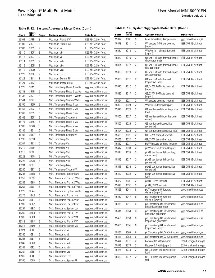
47
User Manual MN150001ENEffective July 2019
Power Xpert® Multi-Point MeterUser Manual
EATON www.eaton.com
Table B. 12. System/Aggregate Meter Data. (Cont.)
StartStart (Hex) Regs. System Values Data Type
15104 3AFF 2 Maximum Phase 3 VA IEEE 754 32-bit float
15106 3B01 2 Maximum System VA IEEE 754 32-bit float
15108 3B03 2 Maximum Va IEEE 754 32-bit float
15110 3B05 2 Maximum Vb IEEE 754 32-bit float
15112 3B07 2 Maximum Vc IEEE 754 32-bit float
15114 3B09 2 Maximum Vab IEEE 754 32-bit float
15116 3B0B 2 Maximum Vbc IEEE 754 32-bit float
15118 3B0D 2 Maximum Vca IEEE 754 32-bit float
15120 3B0F 2 Maximum Freq IEEE 754 32-bit float
15122 3B11 2 Maximum System PF IEEE 754 32-bit float
15124 3B13 2 Maximum Temperature IEEE 754 32-bit float
15126 3B15 6 Min. Timestamp Phase 1 Watts yyyy,mm,dd,hh,mm,ss
15132 3B1B 6 Min. Timestamp Phase 2 Watts yyyy,mm,dd,hh,mm,ss
15138 3B21 6 Min. Timestamp Phase 3 Watts yyyy,mm,dd,hh,mm,ss
15144 3B27 6 Min. Timestamp System Watts yyyy,mm,dd,hh,mm,ss
15150 3B2D 6 Min. Timestamp Phase 1 var yyyy,mm,dd,hh,mm,ss
15156 3B33 6 Min. Timestamp Phase 2 var yyyy,mm,dd,hh,mm,ss
15162 3B39 6 Min. Timestamp Phase 3 var yyyy,mm,dd,hh,mm,ss
15168 3B3F 6 Min. Timestamp System var yyyy,mm,dd,hh,mm,ss
15174 3B45 6 Min. Timestamp Phase 1 VA yyyy,mm,dd,hh,mm,ss
15180 3B4B 6 Min. Timestamp Phase 2 VA yyyy,mm,dd,hh,mm,ss
15186 3B51 6 Min. Timestamp Phase 3 VA yyyy,mm,dd,hh,mm,ss
15192 3B57 6 Min. Timestamp System VA yyyy,mm,dd,hh,mm,ss
15198 3B5D 6 Min. Timestamp Va yyyy,mm,dd,hh,mm,ss
15204 3B63 6 Min. Timestamp Vb yyyy,mm,dd,hh,mm,ss
15210 3B69 6 Min. Timestamp Vc yyyy,mm,dd,hh,mm,ss
15216 3B6F 6 Min. Timestamp Vab yyyy,mm,dd,hh,mm,ss
15222 3B75 6 Min. Timestamp Vbc yyyy,mm,dd,hh,mm,ss
15228 3B7B 6 Min. Timestamp Vca yyyy,mm,dd,hh,mm,ss
15234 3B81 6 Min. Timestamp Freq yyyy,mm,dd,hh,mm,ss
15240 3B87 6 Min. Timestamp System PF yyyy,mm,dd,hh,mm,ss
15246 3B8D 6 Min. Timestamp Temperature yyyy,mm,dd,hh,mm,ss
15252 3B93 6 Max. Timestamp Phase 1 Watts yyyy,mm,dd,hh,mm,ss
15258 3B99 6 Max. Timestamp Phase 2 Watts yyyy,mm,dd,hh,mm,ss
15264 3B9F 6 Max. Timestamp Phase 3 Watts yyyy,mm,dd,hh,mm,ss
15270 3BA5 6 Max. Timestamp System Watts yyyy,mm,dd,hh,mm,ss
15276 3BAB 6 Max. Timestamp Phase 1 var yyyy,mm,dd,hh,mm,ss
15282 3BB1 6 Max. Timestamp Phase 2 var yyyy,mm,dd,hh,mm,ss
15288 3BB7 6 Max. Timestamp Phase 3 var yyyy,mm,dd,hh,mm,ss
15294 3BBD 6 Max. Timestamp System var yyyy,mm,dd,hh,mm,ss
15300 3BC3 6 Max. Timestamp Phase 1 VA yyyy,mm,dd,hh,mm,ss
15306 3BC9 6 Max. Timestamp Phase 2 VA yyyy,mm,dd,hh,mm,ss
15312 3BCF 6 Max. Timestamp Phase 3 VA yyyy,mm,dd,hh,mm,ss
15318 3BD5 6 Max. Timestamp System VA yyyy,mm,dd,hh,mm,ss
15324 3BDB 6 Max. Timestamp Va yyyy,mm,dd,hh,mm,ss
15330 3BE1 6 Max. Timestamp Vb yyyy,mm,dd,hh,mm,ss
15336 3BE7 6 Max. Timestamp Vc yyyy,mm,dd,hh,mm,ss
15342 3BED 6 Max. Timestamp Vab yyyy,mm,dd,hh,mm,ss
15348 3BF3 6 Max. Timestamp Vbc yyyy,mm,dd,hh,mm,ss
15354 3BF9 6 Max. Timestamp Vca yyyy,mm,dd,hh,mm,ss
15360 3BFF 6 Max. Timestamp Freq yyyy,mm,dd,hh,mm,ss
15366 3C05 6 Max. Timestamp System PF yyyy,mm,dd,hh,mm,ss
Table B. 12. System/Aggregate Meter Data. (Cont.)
StartStart (Hex) Regs. System Values Data Type
15372 3C0B 6 Max. Timestamp Temperature yyyy,mm,dd,hh,mm,ss
15378 3C11 2 W forward 1-Minute demand (import)
IEEE 754 32-bit float
15380 3C13 2 W reverse 1-Minute demand (export)
IEEE 754 32-bit float
15382 3C15 2 Q1 var 1-Minute demand (induc-tive/motor load)
IEEE 754 32-bit float
15384 3C17 2 Q2 var 1-Minute demand (induc-tive generator)
IEEE 754 32-bit float
15386 3C19 2 Q3 var 1-Minute demand (capac-itive generator)
IEEE 754 32-bit float
15388 3C1B 2 Q4 var 1-Minute demand (capacitive load)
IEEE 754 32-bit float
15390 3C1D 2 Q1,Q4 VA 1-Minute demand (import)
IEEE 754 32-bit float
15392 3C1F 2 Q2,Q3 VA 1-Minute demand (export)
IEEE 754 32-bit float
15394 3C21 2 W forward demand (import) IEEE 754 32-bit float
15396 3C23 2 W reverse demand (export) IEEE 754 32-bit float
15398 3C25 2 Q1 var demand (inductive/motor load)
IEEE 754 32-bit float
15400 3C27 2 Q2 var demand (inductive gen-erator)
IEEE 754 32-bit float
15402 3C29 2 Q3 var demand (capacitive generator)
IEEE 754 32-bit float
15404 3C2B 2 Q4 var demand (capacitive load) IEEE 754 32-bit float
15406 3C2D 2 Q1,Q4 VA demand (import) IEEE 754 32-bit float
15408 3C2F 2 Q2,Q3 VA demand (export) IEEE 754 32-bit float
15410 3C31 2 pk W forward demand (import) IEEE 754 32-bit float
15412 3C33 2 pk W reverse demand (export) IEEE 754 32-bit float
15414 3C35 2 pk Q1 var demand (inductive/motor load)
IEEE 754 32-bit float
15416 3C37 2 pk Q2 var demand (inductive generator)
IEEE 754 32-bit float
15418 3C39 2 pk Q3 var demand (capacitive generator)
IEEE 754 32-bit float
15420 3C3B 2 pk Q4 var demand (capacitive load)
IEEE 754 32-bit float
15422 3C3D 2 pk Q1,Q4 VA (import) IEEE 754 32-bit float
15424 3C3F 2 pk Q2,Q3 VA (export) IEEE 754 32-bit float
15426 3C41 6 pk Timestamp W forward demand (import)
yyyy,mm,dd,hh,mm,ss
15432 3C47 6 pk Timestamp W reverse demand (export)
yyyy,mm,dd,hh,mm,ss
15438 3C4D 6 pk Timestamp Q1 var demand (inductive/motor load)
yyyy,mm,dd,hh,mm,ss
15444 3C53 6 pk Timestamp Q2 var demand (inductive generator)
yyyy,mm,dd,hh,mm,ss
15450 3C59 6 pk Timestamp Q3 var demand (capacitive generator)
yyyy,mm,dd,hh,mm,ss
15456 3C5F 6 pk Timestamp Q4 var demand (capacitive load)
yyyy,mm,dd,hh,mm,ss
15462 3C65 6 pk Timestamp Q1,Q4 VA (import) yyyy,mm,dd,hh,mm,ss
15468 3C6B 6 pk Timestamp Q2,Q3 VA (export) yyyy,mm,dd,hh,mm,ss
15474 3C71 2 Forward 0.1 kWh (import) 32-bit unsigned integer
15476 3C73 2 Reverse 0.1 kWh (export) 32-bit unsigned integer
15478 3C75 2 Q1 0.1 kvarh (inductive/motor load)
32-bit unsigned integer
15480 3C77 2 Q2 0.1 kvarh (inductive genera-tor)
32-bit unsigned integer
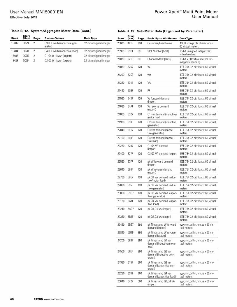
48
User Manual MN150001ENEffective July 2019
Power Xpert® Multi-Point MeterUser Manual
EATON www.eaton.com
Table B. 12. System/Aggregate Meter Data. (Cont.)
StartStart (Hex) Regs. System Values Data Type
15482 3C79 2 Q3 0.1 kvarh (capacitive gen-erator)
32-bit unsigned integer
15484 3C7B 2 Q4 0.1 kvarh (capacitive load) 32-bit unsigned integer
15486 3C7D 2 Q1,Q4 0.1 kVAh (import) 32-bit unsigned integer
15488 3C7F 2 Q2,Q3 0.1 kVAh (export) 32-bit unsigned integer
Table B. 13. Sub-Meter Data (Organized by Parameter). (Cont.)
StartStart (Hex) Regs. Each Up to 60 Meters Data Type
20000 4E1F 960 Customer/Load Name ASCII strings (32 characters) x 60 virtual meters
20960 51DF 60 Slot Number.[1-10] 16-bit unsigned integer x 60 virtual meters
21020 521B 60 Channel Mask [6bits] 16-bit x 60 virtual meters [bit-mapped channels]
21080 5257 120 W IEEE 754 32-bit float x 60 virtual meters
21200 52CF 120 var IEEE 754 32-bit float x 60 virtual meters
21320 5347 120 VA IEEE 754 32-bit float x 60 virtual meters
21440 53BF 120 PF IEEE 754 32-bit float x 60 virtual meters
21560 5437 120 W forward demand (import)
IEEE 754 32-bit float x 60 virtual meters
21680 54AF 120 W reverse demand (export)
IEEE 754 32-bit float x 60 virtual meters
21800 5527 120 Q1 var demand (inductive/motor load)
IEEE 754 32-bit float x 60 virtual meters
21920 559F 120 Q2 var demand (inductive generator)
IEEE 754 32-bit float x 60 virtual meters
22040 5617 120 Q3 var demand (capaci-tive generator)
IEEE 754 32-bit float x 60 virtual meters
22160 568F 120 Q4 var demand (capaci-tive load)
IEEE 754 32-bit float x 60 virtual meters
22280 5707 120 Q1,Q4 VA demand (import)
IEEE 754 32-bit float x 60 virtual meters
22400 577F 120 Q2,Q3 VA demand (export) IEEE 754 32-bit float x 60 virtual meters
22520 57F7 120 pk W forward demand (import)
IEEE 754 32-bit float x 60 virtual meters
22640 586F 120 pk W reverse demand (export)
IEEE 754 32-bit float x 60 virtual meters
22760 58E7 120 pk Q1 var demand (induc-tive/motor load)
IEEE 754 32-bit float x 60 virtual meters
22880 595F 120 pk Q2 var demand (induc-tive generator)
IEEE 754 32-bit float x 60 virtual meters
23000 59D7 120 pk Q3 var demand (capac-itive generator)
IEEE 754 32-bit float x 60 virtual meters
23120 5A4F 120 pk Q4 var demand (capac-itive load)
IEEE 754 32-bit float x 60 virtual meters
23240 5AC7 120 pk Q1,Q4 VA (import) IEEE 754 32-bit float x 60 virtual meters
23360 5B3F 120 pk Q2,Q3 VA (export) IEEE 754 32-bit float x 60 virtual meters
23480 5BB7 360 pk Timestamp W forward demand (import)
yyyy,mm,dd,hh,mm,ss x 60 vir-tual meters
23840 5D1F 360 pk Timestamp W reverse demand (export)
yyyy,mm,dd,hh,mm,ss x 60 vir-tual meters
24200 5E87 360 pk Timestamp Q1 var demand (inductive/motor load)
yyyy,mm,dd,hh,mm,ss x 60 vir-tual meters
24560 5FEF 360 pk Timestamp Q2 var demand (inductive gen-erator)
yyyy,mm,dd,hh,mm,ss x 60 vir-tual meters
24920 6157 360 pk Timestamp Q3 var demand (capacitive gen-erator)
yyyy,mm,dd,hh,mm,ss x 60 vir-tual meters
25280 62BF 360 pk Timestamp Q4 var demand (capacitive load)
yyyy,mm,dd,hh,mm,ss x 60 vir-tual meters
25640 6427 360 pk Timestamp Q1,Q4 VA (import)
yyyy,mm,dd,hh,mm,ss x 60 vir-tual meters
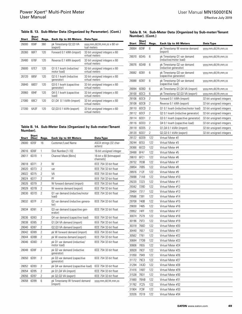
49
User Manual MN150001ENEffective July 2019
Power Xpert® Multi-Point MeterUser Manual
EATON www.eaton.com
Table B. 13. Sub-Meter Data (Organized by Parameter). (Cont.)
StartStart (Hex) Regs. Each Up to 60 Meters Data Type
26000 658F 360 pk Timestamp Q2,Q3 VA (export)
yyyy,mm,dd,hh,mm,ss x 60 vir-tual meters
26360 66F7 120 Forward 0.1 kWh (import) 32-bit unsigned integers x 60 virtual meters
26480 676F 120 Reverse 0.1 kWh (export) 32-bit unsigned integers x 60 virtual meters
26600 67E7 120 Q1 0.1 kvarh (inductive/motor load)
32-bit unsigned integers x 60 virtual meters
26720 685F 120 Q2 0.1 kvarh (inductive generator)
32-bit unsigned integers x 60 virtual meters
26840 68D7 120 Q3 0.1 kvarh (capacitive generator)
32-bit unsigned integers x 60 virtual meters
26960 694F 120 Q4 0.1 kvarh (capacitive load)
32-bit unsigned integers x 60 virtual meters
27080 69C7 120 Q1,Q4 0.1 kVAh (import) 32-bit unsigned integers x 60 virtual meters
27200 6A3F 120 Q2,Q3 0.1 kVAh (export) 32-bit unsigned integers x 60 virtual meters
Table B. 14. Sub-Meter Data (Organized by Sub-meter/Tenant Number). (Cont.)
StartStart (Hex) Regs. Each Up to 60 Meters Data Type
28000 6D5F 16 Customer/Load Name ASCII strings (32 char-acters)
28016 6D6F 1 Slot Number.[1-10] 16-bit unsigned integer
28017 6D70 1 Channel Mask [6bits] 16-bit x 60 [bitmapped channels]
28018 6D71 2 W IEEE 754 32-bit float
28020 6D73 2 var IEEE 754 32-bit float
28022 6D75 2 VA IEEE 754 32-bit float
28024 6D77 2 PF IEEE 754 32-bit float
28026 6D79 2 W forward demand (import) IEEE 754 32-bit float
28028 6D7B 2 W reverse demand (export) IEEE 754 32-bit float
28030 6D7D 2 Q1 var demand (inductive/motor load)
IEEE 754 32-bit float
28032 6D7F 2 Q2 var demand (inductive genera-tor)
IEEE 754 32-bit float
28034 6D81 2 Q3 var demand (capacitive gen-erator)
IEEE 754 32-bit float
28036 6D83 2 Q4 var demand (capacitive load) IEEE 754 32-bit float
28038 6D85 2 Q1,Q4 VA demand (import) IEEE 754 32-bit float
28040 6D87 2 Q2,Q3 VA demand (export) IEEE 754 32-bit float
28042 6D89 2 pk W forward demand (import) IEEE 754 32-bit float
28044 6D8B 2 pk W reverse demand (export) IEEE 754 32-bit float
28046 6D8D 2 pk Q1 var demand (inductive/motor load)
IEEE 754 32-bit float
28048 6D8F 2 pk Q2 var demand (inductive generator)
IEEE 754 32-bit float
28050 6D91 2 pk Q3 var demand (capacitive generator)
IEEE 754 32-bit float
28052 6D93 2 pk Q4 var demand (capacitive load) IEEE 754 32-bit float
28054 6D95 2 pk Q1,Q4 VA (import) IEEE 754 32-bit float
28056 6D97 2 pk Q2,Q3 VA (export) IEEE 754 32-bit float
28058 6D99 6 pk Timestamp W forward demand (import)
yyyy,mm,dd,hh,mm,ss
Table B. 14. Sub-Meter Data (Organized by Sub-meter/Tenant Number). (Cont.)
StartStart (Hex) Regs. Each Up to 60 Meters Data Type
28064 6D9F 6 pk Timestamp W reverse demand (export)
yyyy,mm,dd,hh,mm,ss
28070 6DA5 6 pk Timestamp Q1 var demand (inductive/motor load)
yyyy,mm,dd,hh,mm,ss
28076 6DAB 6 pk Timestamp Q2 var demand (inductive generator)
yyyy,mm,dd,hh,mm,ss
28082 6DB1 6 pk Timestamp Q3 var demand (capacitive generator)
yyyy,mm,dd,hh,mm,ss
28088 6DB7 6 pk Timestamp Q4 var demand (capacitive load)
yyyy,mm,dd,hh,mm,ss
28094 6DBD 6 pk Timestamp Q1,Q4 VA (import) yyyy,mm,dd,hh,mm,ss
28100 6DC3 6 pk Timestamp Q2,Q3 VA (export) yyyy,mm,dd,hh,mm,ss
28106 6DC9 2 Forward 0.1 kWh (import) 32-bit unsigned integers
28108 6DCB 2 Reverse 0.1 kWh (export) 32-bit unsigned integers
28110 6DCD 2 Q1 0.1 kvarh (inductive/motor load) 32-bit unsigned integers
28112 6DCF 2 Q2 0.1 kvarh (inductive generator) 32-bit unsigned integers
28114 6DD1 2 Q3 0.1 kvarh (capacitive generator) 32-bit unsigned integers
28116 6DD3 2 Q4 0.1 kvarh (capacitive load) 32-bit unsigned integers
28118 6DD5 2 Q1,Q4 0.1 kVAh (import) 32-bit unsigned integers
28120 6DD7 2 Q2,Q3 0.1 kVAh (export) 32-bit unsigned integers
28122 6DD9 122 Virtual Meter #2
28244 6E53 122 Virtual Meter #3
28366 6ECD 122 Virtual Meter #4
28488 6F47 122 Virtual Meter #5
28610 6FC1 122 Virtual Meter #6
28732 703B 122 Virtual Meter #7
28854 70B5 122 Virtual Meter #8
28976 712F 122 Virtual Meter #9
29098 71A9 122 Virtual Meter #10
29220 7223 122 Virtual Meter #11
29342 729D 122 Virtual Meter #12
29464 7317 122 Virtual Meter #13
29586 7391 122 Virtual Meter #14
29708 740B 122 Virtual Meter #15
29830 7485 122 Virtual Meter #16
29952 74FF 122 Virtual Meter #17
30074 7579 122 Virtual Meter #18
30196 75F3 122 Virtual Meter #19
30318 766D 122 Virtual Meter #20
30440 76E7 122 Virtual Meter #21
30562 7761 122 Virtual Meter #22
30684 77DB 122 Virtual Meter #23
30806 7855 122 Virtual Meter #24
30928 78CF 122 Virtual Meter #25
31050 7949 122 Virtual Meter #26
31172 79C3 122 Virtual Meter #27
31294 7A3D 122 Virtual Meter #28
31416 7AB7 122 Virtual Meter #29
31538 7B31 122 Virtual Meter #30
31660 7BAB 122 Virtual Meter #31
31782 7C25 122 Virtual Meter #32
31904 7C9F 122 Virtual Meter #33
32026 7D19 122 Virtual Meter #34
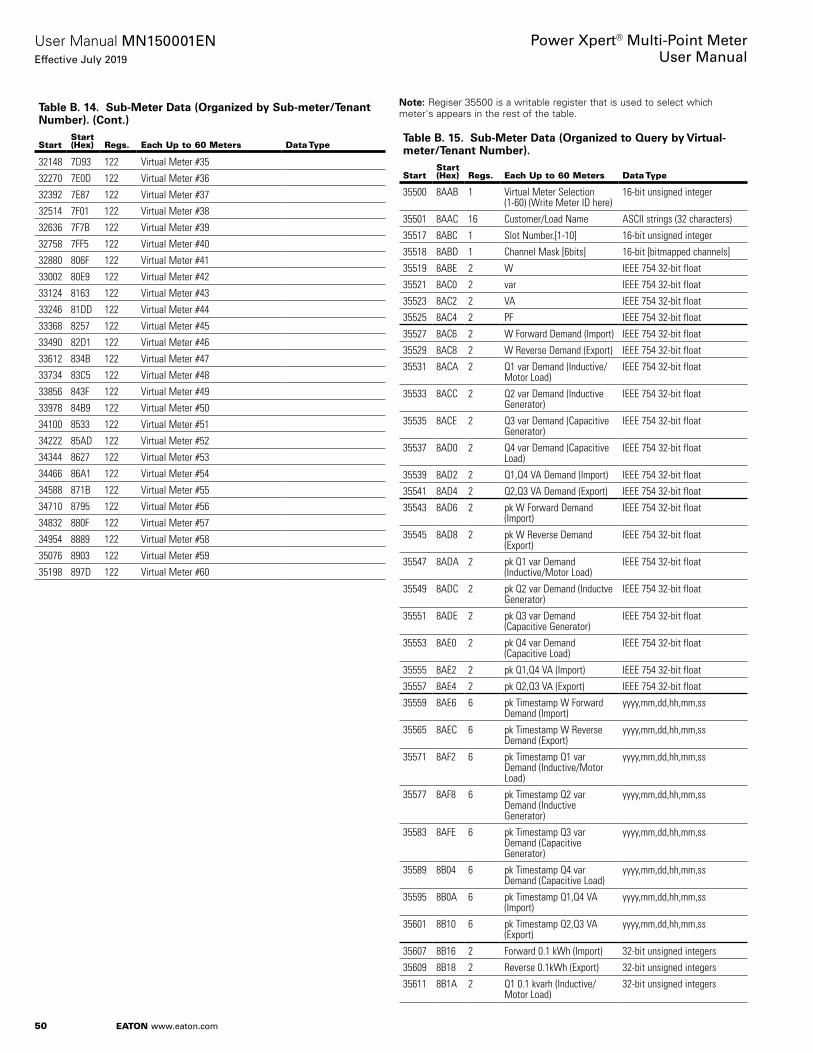
50
User Manual MN150001ENEffective July 2019
Power Xpert® Multi-Point MeterUser Manual
EATON www.eaton.com
Table B. 14. Sub-Meter Data (Organized by Sub-meter/Tenant Number). (Cont.)
StartStart (Hex) Regs. Each Up to 60 Meters Data Type
32148 7D93 122 Virtual Meter #35
32270 7E0D 122 Virtual Meter #36
32392 7E87 122 Virtual Meter #37
32514 7F01 122 Virtual Meter #38
32636 7F7B 122 Virtual Meter #39
32758 7FF5 122 Virtual Meter #40
32880 806F 122 Virtual Meter #41
33002 80E9 122 Virtual Meter #42
33124 8163 122 Virtual Meter #43
33246 81DD 122 Virtual Meter #44
33368 8257 122 Virtual Meter #45
33490 82D1 122 Virtual Meter #46
33612 834B 122 Virtual Meter #47
33734 83C5 122 Virtual Meter #48
33856 843F 122 Virtual Meter #49
33978 84B9 122 Virtual Meter #50
34100 8533 122 Virtual Meter #51
34222 85AD 122 Virtual Meter #52
34344 8627 122 Virtual Meter #53
34466 86A1 122 Virtual Meter #54
34588 871B 122 Virtual Meter #55
34710 8795 122 Virtual Meter #56
34832 880F 122 Virtual Meter #57
34954 8889 122 Virtual Meter #58
35076 8903 122 Virtual Meter #59
35198 897D 122 Virtual Meter #60
otee:N Regiser 35500 is a writable register that is used to select which meter's appears in the rest of the table .
Table B. 15. Sub-Meter Data (Organized to Query by Virtual-meter/Tenant Number). (Cont.)
StartStart (Hex) Regs. Each Up to 60 Meters Data Type
35500 8AAB 1 Virtual Meter Selection (1-60) (Write Meter ID here)
16-bit unsigned integer
35501 8AAC 16 Customer/Load Name ASCII strings (32 characters)
35517 8ABC 1 Slot Number.[1-10] 16-bit unsigned integer
35518 8ABD 1 Channel Mask [6bits] 16-bit [bitmapped channels]
35519 8ABE 2 W IEEE 754 32-bit float
35521 8AC0 2 var IEEE 754 32-bit float
35523 8AC2 2 VA IEEE 754 32-bit float
35525 8AC4 2 PF IEEE 754 32-bit float
35527 8AC6 2 W Forward Demand (Import) IEEE 754 32-bit float
35529 8AC8 2 W Reverse Demand (Export) IEEE 754 32-bit float
35531 8ACA 2 Q1 var Demand (Inductive/Motor Load)
IEEE 754 32-bit float
35533 8ACC 2 Q2 var Demand (Inductive Generator)
IEEE 754 32-bit float
35535 8ACE 2 Q3 var Demand (Capacitive Generator)
IEEE 754 32-bit float
35537 8AD0 2 Q4 var Demand (Capacitive Load)
IEEE 754 32-bit float
35539 8AD2 2 Q1,Q4 VA Demand (Import) IEEE 754 32-bit float
35541 8AD4 2 Q2,Q3 VA Demand (Export) IEEE 754 32-bit float
35543 8AD6 2 pk W Forward Demand (Import)
IEEE 754 32-bit float
35545 8AD8 2 pk W Reverse Demand (Export)
IEEE 754 32-bit float
35547 8ADA 2 pk Q1 var Demand (Inductive/Motor Load)
IEEE 754 32-bit float
35549 8ADC 2 pk Q2 var Demand (Inductve Generator)
IEEE 754 32-bit float
35551 8ADE 2 pk Q3 var Demand (Capacitive Generator)
IEEE 754 32-bit float
35553 8AE0 2 pk Q4 var Demand (Capacitive Load)
IEEE 754 32-bit float
35555 8AE2 2 pk Q1,Q4 VA (Import) IEEE 754 32-bit float
35557 8AE4 2 pk Q2,Q3 VA (Export) IEEE 754 32-bit float
35559 8AE6 6 pk Timestamp W Forward Demand (Import)
yyyy,mm,dd,hh,mm,ss
35565 8AEC 6 pk Timestamp W Reverse Demand (Export)
yyyy,mm,dd,hh,mm,ss
35571 8AF2 6 pk Timestamp Q1 var Demand (Inductive/Motor Load)
yyyy,mm,dd,hh,mm,ss
35577 8AF8 6 pk Timestamp Q2 var Demand (Inductive Generator)
yyyy,mm,dd,hh,mm,ss
35583 8AFE 6 pk Timestamp Q3 var Demand (Capacitive Generator)
yyyy,mm,dd,hh,mm,ss
35589 8B04 6 pk Timestamp Q4 var Demand (Capacitive Load)
yyyy,mm,dd,hh,mm,ss
35595 8B0A 6 pk Timestamp Q1,Q4 VA (Import)
yyyy,mm,dd,hh,mm,ss
35601 8B10 6 pk Timestamp Q2,Q3 VA (Export)
yyyy,mm,dd,hh,mm,ss
35607 8B16 2 Forward 0.1 kWh (Import) 32-bit unsigned integers
35609 8B18 2 Reverse 0.1kWh (Export) 32-bit unsigned integers
35611 8B1A 2 Q1 0.1 kvarh (Inductive/Motor Load)
32-bit unsigned integers

51
User Manual MN150001ENEffective July 2019
Power Xpert® Multi-Point MeterUser Manual
EATON www.eaton.com
Table B. 15. Sub-Meter Data (Organized to Query by Virtual-meter/Tenant Number). (Cont.)
StartStart (Hex) Regs. Each Up to 60 Meters Data Type
35613 8B1C 2 Q2 0.1 kvarh (Inductive Generator)
32-bit unsigned integers
35615 8B1E 2 Q3 0.1 kvarh (Capacitive Generator)
32-bit unsigned integers
35617 8B20 2 Q4 0.1 kvarh (Capacitive Load)
32-bit unsigned integers
35619 8B22 2 Q1, Q4 0.1 kVAh (Import) 32-bit unsigned integers
35621 8B24 2 Q2,Q3 0.1 kVAh (Export) 32-bit unsigned integers
35623 8B26 2 V1 IEEE 754 32-bit float
35625 8B28 2 V2 IEEE 754 32-bit float
35627 8B2A 2 V3 IEEE 754 32-bit float
35629 8B2C 2 Freq IEEE 754 32-bit float
Table B. 16. Input Slot Data (Organized by Parameter).
StartStart (Hex) Regs. Each Up to 80 Inputs Data Type
40500 9E33 1280 Input Name ASCII strings (32 characters) x 80 inputs
41780 A333 80 Slot Number.[1-10] 16-bit unsigned integer x 80 inputs
41860 A383 80 Channel Number [1-8] 16-bit x 80 inputs
41940 A3D3 80 Input Rollover Counter 16-bit unsigned integers x 80 inputs
42020 A423 160 Input Counter 32-bit unsigned integers x 80 inputs
42180 A4C3 160 Input Multiplier Setting IEEE 754 32-bit float x 80 inputs
42340 A563 640 Units ASCII strings (16 characters) x 80 inputs
42980 A7E3 160 Input Profile IEEE 754 32-bit float x 80 inputs
Table B. 17. Input Slot Data (Organized by Input Slot/Channel). (Cont.)
StartStart (Hex) Regs. Each Up to 80 Inputs Data Type
43200 A8BF 16 Input Name ASCII strings (32 characters)
43216 A8CF 1 Slot Number.[1-10] 16-bit unsigned integer
43217 A8D0 1 Channel Number [1-8] 16-bit
43218 A8D1 1 Input Rollover Counter 16-bit unsigned integer
43219 A8D2 2 Input Counter 32-bit unsigned integer
43221 A8D4 2 Input Multiplier Setting IEEE 754 32-bit float
43223 A8D6 8 Units ASCII strings (16 characters)
43231 A8DE 2 Input Profile IEEE 754 32-bit float (average value)
43233 A8E0 33 Input #2 Slot#1 Input#2
43266 A901 33 Input #3 Slot#1 Input#3
43299 A922 33 Input #4 Slot#1 Input#4
43332 A943 33 Input #5 Slot#1 Input#5
43365 A964 33 Input #6 Slot#1 Input#6
43398 A985 33 Input #7 Slot#1 Input#7
43431 A9A6 33 Input #8 Slot#1 Input#8
43464 A9C7 33 Input #9 Slot#2 Input#1
43497 A9E8 33 Input #10 Slot#2 Input#2
43530 AA09 33 Input #11 Slot#2 Input#3
43563 AA2A 33 Input #12 Slot#2 Input#4
Table B. 17. Input Slot Data (Organized by Input Slot/Channel). (Cont.)
StartStart (Hex) Regs. Each Up to 80 Inputs Data Type
43596 AA4B 33 Input #13 Slot#2 Input#5
43629 AA6C 33 Input #14 Slot#2 Input#6
43662 AA8D 33 Input #15 Slot#2 Input#7
43695 AAAE 33 Input #16 Slot#2 Input#8
43728 AACF 33 Input #17 Slot#3 Input#1
43761 AAF0 33 Input #18 Slot#3 Input#2
43794 AB11 33 Input #19 Slot#3 Input#3
43827 AB32 33 Input #20 Slot#3 Input#4
43860 AB53 33 Input #21 Slot#3 Input#5
43893 AB74 33 Input #22 Slot#3 Input#6
43926 AB95 33 Input #23 Slot#3 Input#7
43959 ABB6 33 Input #24 Slot#3 Input#8
43992 ABD7 33 Input #25 Slot#4 Input#1
44025 ABF8 33 Input #26 Slot#4 Input#2
44058 AC19 33 Input #27 Slot#4 Input#3
44091 AC3A 33 Input #28 Slot#4 Input#4
44124 AC5B 33 Input #29 Slot#4 Input#5
44157 AC7C 33 Input #30 Slot#4 Input#6
44190 AC9D 33 Input #31 Slot#4 Input#7
44223 ACBE 33 Input #32 Slot#4 Input#8
44256 ACDF 33 Input #33 Slot#5 Input#1
44289 AD00 33 Input #34 Slot#5 Input#2
44322 AD21 33 Input #35 Slot#5 Input#3
44355 AD42 33 Input #36 Slot#5 Input#4
44388 AD63 33 Input #37 Slot#5 Input#5
44421 AD84 33 Input #38 Slot#5 Input#6
44454 ADA5 33 Input #39 Slot#5 Input#7
44487 ADC6 33 Input #40 Slot#5 Input#8
44520 ADE7 33 Input #41 Slot#6 Input#1
44553 AE08 33 Input #42 Slot#6 Input#2
44586 AE29 33 Input #43 Slot#6 Input#3
44619 AE4A 33 Input #44 Slot#6 Input#4
44652 AE6B 33 Input #45 Slot#6 Input#5
44685 AE8C 33 Input #46 Slot#6 Input#6
44718 AEAD 33 Input #47 Slot#6 Input#7
44751 AECE 33 Input #48 Slot#6 Input#8
44784 AEEF 33 Input #49 Slot#7 Input#1
44817 AF10 33 Input #50 Slot#7 Input#2
44850 AF31 33 Input #51 Slot#7 Input#3
44883 AF52 33 Input #52 Slot#7 Input#4
44916 AF73 33 Input #53 Slot#7 Input#5
44949 AF94 33 Input #54 Slot7 Input#6
44982 AFB5 33 Input #55 Slot#7 Input#7
45015 AFD6 33 Input #56 Slot#7 Input#8
45048 AFF7 33 Input #57 Slot#8 Input#1
45081 B018 33 Input #58 Slot#8 Input#2
45114 B039 33 Input #59 Slot#8 Input#3
45147 B05A 33 Input #60 Slot#8 Input#4
45180 B07B 33 Input #61 Slot#8 Input#5
45213 B09C 33 Input #62 Slot#8 Input#6
45246 B0BD 33 Input #63 Slot#8 Input#7
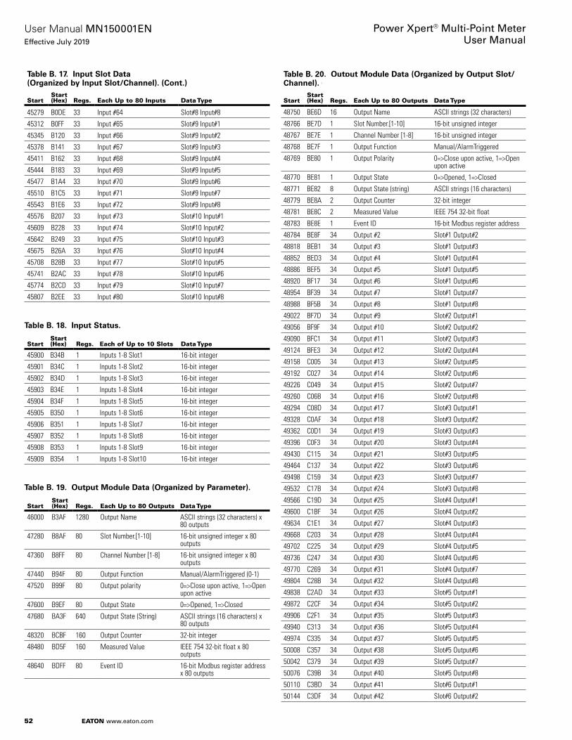
52
User Manual MN150001ENEffective July 2019
Power Xpert® Multi-Point MeterUser Manual
EATON www.eaton.com
Table B. 17. Input Slot Data (Organized by Input Slot/Channel). (Cont.)
StartStart (Hex) Regs. Each Up to 80 Inputs Data Type
45279 B0DE 33 Input #64 Slot#8 Input#8
45312 B0FF 33 Input #65 Slot#9 Input#1
45345 B120 33 Input #66 Slot#9 Input#2
45378 B141 33 Input #67 Slot#9 Input#3
45411 B162 33 Input #68 Slot#9 Input#4
45444 B183 33 Input #69 Slot#9 Input#5
45477 B1A4 33 Input #70 Slot#9 Input#6
45510 B1C5 33 Input #71 Slot#9 Input#7
45543 B1E6 33 Input #72 Slot#9 Input#8
45576 B207 33 Input #73 Slot#10 Input#1
45609 B228 33 Input #74 Slot#10 Input#2
45642 B249 33 Input #75 Slot#10 Input#3
45675 B26A 33 Input #76 Slot#10 Input#4
45708 B28B 33 Input #77 Slot#10 Input#5
45741 B2AC 33 Input #78 Slot#10 Input#6
45774 B2CD 33 Input #79 Slot#10 Input#7
45807 B2EE 33 Input #80 Slot#10 Input#8
Table B. 18. Input Status.
StartStart (Hex) Regs. Each of Up to 10 Slots Data Type
45900 B34B 1 Inputs 1-8 Slot1 16-bit integer
45901 B34C 1 Inputs 1-8 Slot2 16-bit integer
45902 B34D 1 Inputs 1-8 Slot3 16-bit integer
45903 B34E 1 Inputs 1-8 Slot4 16-bit integer
45904 B34F 1 Inputs 1-8 Slot5 16-bit integer
45905 B350 1 Inputs 1-8 Slot6 16-bit integer
45906 B351 1 Inputs 1-8 Slot7 16-bit integer
45907 B352 1 Inputs 1-8 Slot8 16-bit integer
45908 B353 1 Inputs 1-8 Slot9 16-bit integer
45909 B354 1 Inputs 1-8 Slot10 16-bit integer
Table B. 19. Output Module Data (Organized by Parameter).
StartStart (Hex) Regs. Each Up to 80 Outputs Data Type
46000 B3AF 1280 Output Name ASCII strings (32 characters) x 80 outputs
47280 B8AF 80 Slot Number.[1-10] 16-bit unsigned integer x 80 outputs
47360 B8FF 80 Channel Number [1-8] 16-bit unsigned integer x 80 outputs
47440 B94F 80 Output Function Manual/AlarmTriggered (0-1)
47520 B99F 80 Output polarity 0=>Close upon active, 1=>Open upon active
47600 B9EF 80 Output State 0=>Opened, 1=>Closed
47680 BA3F 640 Output State (String) ASCII strings (16 characters) x 80 outputs
48320 BCBF 160 Output Counter 32-bit integer
48480 BD5F 160 Measured Value IEEE 754 32-bit float x 80 outputs
48640 BDFF 80 Event ID 16-bit Modbus register address x 80 outputs
Table B. 20. Output Module Data (Organized by Output Slot/Channel). (Cont.)
StartStart (Hex) Regs. Each Up to 80 Outputs Data Type
48750 BE6D 16 Output Name ASCII strings (32 characters)
48766 BE7D 1 Slot Number.[1-10] 16-bit unsigned integer
48767 BE7E 1 Channel Number [1-8] 16-bit unsigned integer
48768 BE7F 1 Output Function Manual/AlarmTriggered
48769 BE80 1 Output Polarity 0=>Close upon active, 1=>Open upon active
48770 BE81 1 Output State 0=>Opened, 1=>Closed
48771 BE82 8 Output State (string) ASCII strings (16 characters)
48779 BE8A 2 Output Counter 32-bit integer
48781 BE8C 2 Measured Value IEEE 754 32-bit float
48783 BE8E 1 Event ID 16-bit Modbus register address
48784 BE8F 34 Output #2 Slot#1 Output#2
48818 BEB1 34 Output #3 Slot#1 Output#3
48852 BED3 34 Output #4 Slot#1 Output#4
48886 BEF5 34 Output #5 Slot#1 Output#5
48920 BF17 34 Output #6 Slot#1 Output#6
48954 BF39 34 Output #7 Slot#1 Output#7
48988 BF5B 34 Output #8 Slot#1 Output#8
49022 BF7D 34 Output #9 Slot#2 Output#1
49056 BF9F 34 Output #10 Slot#2 Output#2
49090 BFC1 34 Output #11 Slot#2 Output#3
49124 BFE3 34 Output #12 Slot#2 Output#4
49158 C005 34 Output #13 Slot#2 Output#5
49192 C027 34 Output #14 Slot#2 Output#6
49226 C049 34 Output #15 Slot#2 Output#7
49260 C06B 34 Output #16 Slot#2 Output#8
49294 C08D 34 Output #17 Slot#3 Output#1
49328 C0AF 34 Output #18 Slot#3 Output#2
49362 C0D1 34 Output #19 Slot#3 Output#3
49396 C0F3 34 Output #20 Slot#3 Output#4
49430 C115 34 Output #21 Slot#3 Output#5
49464 C137 34 Output #22 Slot#3 Output#6
49498 C159 34 Output #23 Slot#3 Output#7
49532 C17B 34 Output #24 Slot#3 Output#8
49566 C19D 34 Output #25 Slot#4 Output#1
49600 C1BF 34 Output #26 Slot#4 Output#2
49634 C1E1 34 Output #27 Slot#4 Output#3
49668 C203 34 Output #28 Slot#4 Output#4
49702 C225 34 Output #29 Slot#4 Output#5
49736 C247 34 Output #30 Slot#4 Output#6
49770 C269 34 Output #31 Slot#4 Output#7
49804 C28B 34 Output #32 Slot#4 Output#8
49838 C2AD 34 Output #33 Slot#5 Output#1
49872 C2CF 34 Output #34 Slot#5 Output#2
49906 C2F1 34 Output #35 Slot#5 Output#3
49940 C313 34 Output #36 Slot#5 Output#4
49974 C335 34 Output #37 Slot#5 Output#5
50008 C357 34 Output #38 Slot#5 Output#6
50042 C379 34 Output #39 Slot#5 Output#7
50076 C39B 34 Output #40 Slot#5 Output#8
50110 C3BD 34 Output #41 Slot#6 Output#1
50144 C3DF 34 Output #42 Slot#6 Output#2

53
User Manual MN150001ENEffective July 2019
Power Xpert® Multi-Point MeterUser Manual
EATON www.eaton.com
Table B. 20. Output Module Data (Organized by Output Slot/Channel). (Cont.)
StartStart (Hex) Regs. Each Up to 80 Outputs Data Type
50178 C401 34 Output #43 Slot#6 Output#3
50212 C423 34 Output #44 Slot#6 Output#4
50246 C445 34 Output #45 Slot#6 Output#5
50280 C467 34 Output #46 Slot#6 Output#6
50314 C489 34 Output #47 Slot#6 Output#7
50348 C4AB 34 Output #48 Slot#6 Output#8
50382 C4CD 34 Output #49 Slot#7 Output#1
50416 C4EF 34 Output #50 Slot#7 Output#2
50450 C511 34 Output #51 Slot#7 Output#3
50484 C533 34 Output #52 Slot#7 Output#4
50518 C555 34 Output #53 Slot#7 Output#5
50552 C577 34 Output #54 Slot#7 Output#6
50586 C599 34 Output #55 Slot#7 Output#7
50620 C5BB 34 Output #56 Slot#7 Output#8
50654 C5DD 34 Output #57 Slot#8 Output#1
50688 C5FF 34 Output #58 Slot#8 Output#2
50722 C621 34 Output #59 Slot#8 Output#3
50756 C643 34 Output #60 Slot#8 Output#4
50790 C665 34 Output #61 Slot#8 Output#5
50824 C687 34 Output #62 Slot#8 Output#6
50858 C6A9 34 Output #63 Slot#8 Output#7
50892 C6CB 34 Output #64 Slot#8 Output#8
50926 C6ED 34 Output #65 Slot#9 Output#1
50960 C70F 34 Output #66 Slot#9 Output#2
50994 C731 34 Output #67 Slot#9 Output#3
51028 C753 34 Output #68 Slot#9 Output#4
51062 C775 34 Output #69 Slot#9 Output#5
51096 C797 34 Output #70 Slot#9 Output#6
51130 C7B9 34 Output #71 Slot#9 Output#7
51164 C7DB 34 Output #72 Slot#9 Output#8
51198 C7FD 34 Output #73 Slot#10 Output#1
51232 C81F 34 Output #74 Slot#10 Output#2
51266 C841 34 Output #75 Slot#10 Output#3
51300 C863 34 Output #76 Slot#10 Output#4
51334 C885 34 Output #77 Slot#10 Output#5
51368 C8A7 34 Output #78 Slot#10 Output#6
51402 C8C9 34 Output #79 Slot#10 Output#7
51436 C8EB 34 Output #80 Slot#10 Output#8
Table B. 21. Output Status.
StartStart (Hex) Regs. Each of Up to 10 Module Data Type
51480 C917 1 Outputs 1-8 Slot 1 16-bit integer
51481 C918 1 Outputs 1-8 Slot 2 16-bit integer
51482 C919 1 Outputs 1-8 Slot 3 16-bit integer
51483 C91A 1 Outputs 1-8 Slot 4 16-bit integer
51484 C91B 1 Outputs 1-8 Slot 5 16-bit integer
51485 C91C 1 Outputs 1-8 Slot 6 16-bit integer
51486 C91D 1 Outputs 1-8 Slot 7 16-bit integer
51487 C91E 1 Outputs 1-8 Slot 8 16-bit integer
51488 C91F 1 Outputs 1-8 Slot 9 16-bit integer
51489 C920 1 Outputs 1-8 Slot 10 16-bit integer
Table B. 22. Built-In Inputs (Organized by Parameter).
StartStart (Hex) Regs. 3 Onboard Data Type
51500 C92B 48 Input Name ASCII strings (32 characters) x 3 inputs
51548 C95B 3 Input Function (0-3) None/PulseInputs/RateAlert/DemandSync (0-3)
51551 C95E 3 Channel Number [1-3] 16-bit x 4 inputs
51554 C961 3 Input State 0=>Opened, 1=>Closed
51557 C964 24 Input State (String) ASCII strings (16 characters) x 3 inputs
51581 C97C 3 Input Rollover Counter 16-bit unsigned integers x 3 inputs
51584 C97F 6 Input Counter 32-bit unsigned integers x 3 inputs
51590 C985 6 Input Multiplier Setting IEEE 754 32-bit float x 3 inputs
51596 C98B 24 Units ASCII strings (16 characters) x 3 inputs
51620 C9A3 6 Input Profile IEEE 754 32-bit float x 3 inputs

54
User Manual MN150001ENEffective July 2019
Power Xpert® Multi-Point MeterUser Manual
EATON www.eaton.com
Table B. 23. Built-In Inputs (Organized by Input).
StartStart (Hex) Regs. Built-In Inputs Data Type
51700 C9F3 1 Input Function (0-3) None/PulseInputs/RateAlert/DemandSync (0-3)
51701 C9F4 1 Input State 0=>Opened, 1=>Closed
51702 C9F5 1 Input Rollover Counter 16-bit unsigned integer
51703 C9F6 2 Input Counter 32-bit unsigned integer
51705 C9F8 2 Input Multiplier IEEE 754 32-bit float
51707 C9FA 8 Units ASCII strings (16 characters)
51715 CA02 2 Input Profile IEEE 754 32-bit float (average value)
51717 CA04 17 Input #2 Built-In Input#2
51734 CA15 17 Input #3 Built-In Input#3
Table B. 24. Built-In Output.
StartStart (Hex) Regs. Built-In Output Data Type
51800 CA57 16 Meter (or Null) ASCII strings (32 characters)
51816 CA67 1 Output Function (2-3) PulseOutput(3),DemandSync(2)
51817 CA68 8 Measurement ASCII strings (16 characters)
51825 CA70 2 Pulse Constant IEEE 754 32-bit float (for PulseOutput)
51827 CA72 1 Output State 0=>Opened, 1=>Closed
51828 CA73 2 Output Counter 32-bit integer
Table B. 25. Virtual/Tenant Demand Data #1. (Cont.)
StartStart (Hex) Regs. Each Up to 60 Meters Data Type
52000 CB1F 1 Sequence# 16-bit unsigned integer
52001 CB20 6 Timestamp of Demand Reset yyyy,mm,dd,hh,mm,ss
52007 CB26 2 pk W Forward Demand (Import)
IEEE 754 32-bit float
52009 CB28 2 pk W Reverse Demand (Export) IEEE 754 32-bit float
52011 CB2A 2 pk Q1 var Demand (Inductive/Motor Load)
IEEE 754 32-bit float
52013 CB2C 2 pk Q2 var Demand (Inductive Generator)
IEEE 754 32-bit float
52015 CB2E 2 pk Q3 var Demand (Capacitive Generator)
IEEE 754 32-bit float
52017 CB30 2 pk Q4 var Demand (Capacitive Load)
IEEE 754 32-bit float
52019 CB32 2 pk Q1,Q4 VA (Import) IEEE 754 32-bit float
52021 CB34 2 pk Q2,Q3 VA (Export) IEEE 754 32-bit float
52023 CB36 6 pk Timestamp W Forward Demand (Import)
yyyy,mm,dd,hh,mm,ss
52029 CB3C 6 pk Timestamp W Reverse Demand (Export)
yyyy,mm,dd,hh,mm,ss
52035 CB42 6 pk Timestamp Q1 var Demand (Inductive/Motor Load)
yyyy,mm,dd,hh,mm,ss
52041 CB48 6 pk Timestamp Q2 var Demand (Inductive Generator)
yyyy,mm,dd,hh,mm,ss
52047 CB4E 6 pk Timestamp Q3 var Demand (Capacitive Generator)
yyyy,mm,dd,hh,mm,ss
52053 CB54 6 pk Timestamp Q4 var Demand (Capacitive Load)
yyyy,mm,dd,hh,mm,ss
52059 CB5A 6 pk Timestamp Q1,Q4 VA (Import)
yyyy,mm,dd,hh,mm,ss
52065 CB60 6 pk Timestamp Q2,Q3 VA (Export)
yyyy,mm,dd,hh,mm,ss
Table B. 25. Virtual/Tenant Demand Data #1. (Cont.)
StartStart (Hex) Regs. Each Up to 60 Meters Data Type
52071 CB66 2 Forward 0.1 kWh (Import) 32-bit unsigned integer
52073 CB68 2 Reverse 0.1 kWh (Export) 32-bit unsigned integer
52075 CB6A 2 Q1 0.1 kvarh (Inductive/Motor Load)
32-bit unsigned integer
52077 CB6C 2 Q2 0.1 kvarh (Inductive Generator)
32-bit unsigned integer
52079 CB6E 2 Q3 0.1 kvarh (Capacitive Generator)
32-bit unsigned integer
52081 CB70 2 Q4 0.1 kvarh (Capacitive Load) 32-bit unsigned integer
52083 CB72 2 Q1,Q4 0.1 kVAh (Import) 32-bit unsigned integer
52085 CB74 2 Q2,Q3 0.1 kVAh (Export) 32-bit unsigned integer
52087 CB76 87 Virtual Meter #1
52174 CBCD 87 Virtual Meter #2
52245 CC14 87 Virtual Meter #3
52332 CC6B 87 Virtual Meter #4
52419 CCC2 87 Virtual Meter #5
52506 CD19 87 Virtual Meter #6
52593 CD70 87 Virtual Meter #7
52680 CDC7 87 Virtual Meter #8
52767 CE1E 87 Virtual Meter #9
52854 CE75 87 Virtual Meter #10
52941 CECC 87 Virtual Meter #11
53028 CF23 87 Virtual Meter #12
53115 CF7A 87 Virtual Meter #13
53202 CFD1 87 Virtual Meter #14
53289 D028 87 Virtual Meter #15
53376 D07F 87 Virtual Meter #16
53463 D0D6 87 Virtual Meter #17
53550 D12D 87 Virtual Meter #18
53637 D184 87 Virtual Meter #19
53724 D1DB 87 Virtual Meter #20
53811 D232 87 Virtual Meter #21
53898 D289 87 Virtual Meter #22
53985 D2E0 87 Virtual Meter #23
54072 D337 87 Virtual Meter #24
54159 D38E 87 Virtual Meter #25
54246 D3E5 87 Virtual Meter #26
54333 D43C 87 Virtual Meter #27
54420 D493 87 Virtual Meter #28
54507 D4EA 87 Virtual Meter #29
54594 D541 87 Virtual Meter #30
54681 D598 87 Virtual Meter #31
54768 D5EF 87 Virtual Meter #32
54855 D646 87 Virtual Meter #33
54942 D69D 87 Virtual Meter #34
55029 D6F4 87 Virtual Meter #35
55116 D74B 87 Virtual Meter #36
55203 D7A2 87 Virtual Meter #37
55290 D7F9 87 Virtual Meter #38
55377 D850 87 Virtual Meter #39
55464 D8A7 87 Virtual Meter #40
55551 D8FE 87 Virtual Meter #41
55638 D955 87 Virtual Meter #42
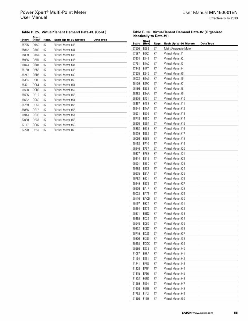
55
User Manual MN150001ENEffective July 2019
Power Xpert® Multi-Point MeterUser Manual
EATON www.eaton.com
Table B. 25. Virtual/Tenant Demand Data #1. (Cont.)
StartStart (Hex) Regs. Each Up to 60 Meters Data Type
55725 D9AC 87 Virtual Meter #43
55812 DA03 87 Virtual Meter #44
55899 DA5A 87 Virtual Meter #45
55986 DAB1 87 Virtual Meter #46
56073 DB08 87 Virtual Meter #47
56160 DB5F 87 Virtual Meter #48
56247 DBB6 87 Virtual Meter #49
56334 DC0D 87 Virtual Meter #50
56421 DC64 87 Virtual Meter #51
56508 DCBB 87 Virtual Meter #52
56595 DD12 87 Virtual Meter #53
56682 DD69 87 Virtual Meter #54
56769 DDC0 87 Virtual Meter #55
56856 DE17 87 Virtual Meter #56
56943 DE6E 87 Virtual Meter #57
57030 DEC5 87 Virtual Meter #58
57117 DF1C 87 Virtual Meter #59
57220 DF83 87 Virtual Meter #60
Table B. 26. Virtual Tenant Demand Data #2 (Organized Identically to Data #1). (Cont.)
StartStart (Hex) Regs. Each Up to 60 Meters Data Type
57500 E09B 87 Main/Aggregate Meter
57587 E0F2 87 Virtual Meter #1
57674 E149 87 Virtual Meter #2
57761 E1A0 87 Virtual Meter #3
57848 E1F7 87 Virtual Meter #4
57935 E24E 87 Virtual Meter #5
58022 E2A5 87 Virtual Meter #6
58109 E2FC 87 Virtual Meter #7
58196 E353 87 Virtual Meter #8
58283 E3AA 87 Virtual Meter #9
58370 E401 87 Virtual Meter #10
58457 E458 87 Virtual Meter #11
58544 E4AF 87 Virtual Meter #12
58631 E506 87 Virtual Meter #13
58718 E55D 87 Virtual Meter #14
58805 E5B4 87 Virtual Meter #15
58892 E60B 87 Virtual Meter #16
58979 E662 87 Virtual Meter #17
59066 E6B9 87 Virtual Meter #18
59153 E710 87 Virtual Meter #19
59240 E767 87 Virtual Meter #20
59327 E7BE 87 Virtual Meter #21
59414 E815 87 Virtual Meter #22
59501 E86C 87 Virtual Meter #23
59588 E8C3 87 Virtual Meter #24
59675 E91A 87 Virtual Meter #25
59762 E971 87 Virtual Meter #26
59849 E9C8 87 Virtual Meter #27
59936 EA1F 87 Virtual Meter #28
60023 EA76 87 Virtual Meter #29
60110 EACD 87 Virtual Meter #30
60197 EB24 87 Virtual Meter #31
60284 EB7B 87 Virtual Meter #32
60371 EBD2 87 Virtual Meter #33
60458 EC29 87 Virtual Meter #34
60545 EC80 87 Virtual Meter #35
60632 ECD7 87 Virtual Meter #36
60719 ED2E 87 Virtual Meter #37
60806 ED85 87 Virtual Meter #38
60893 EDDC 87 Virtual Meter #39
60980 EE33 87 Virtual Meter #40
61067 EE8A 87 Virtual Meter #41
61154 EEE1 87 Virtual Meter #42
61241 EF38 87 Virtual Meter #43
61328 EF8F 87 Virtual Meter #44
61415 EFE6 87 Virtual Meter #45
61502 F03D 87 Virtual Meter #46
61589 F094 87 Virtual Meter #47
61676 F0EB 87 Virtual Meter #48
61763 F142 87 Virtual Meter #49
61850 F199 87 Virtual Meter #50

56
User Manual MN150001ENEffective July 2019
Power Xpert® Multi-Point MeterUser Manual
EATON www.eaton.com
Table B. 26. Virtual Tenant Demand Data #2 (Organized Identically to Data #1). (Cont.)
StartStart (Hex) Regs. Each Up to 60 Meters Data Type
61937 F1F0 87 Virtual Meter #51
62024 F247 87 Virtual Meter #52
62111 F29E 87 Virtual Meter #53
62198 F2F5 87 Virtual Meter #54
62285 F34C 87 Virtual Meter #55
62372 F3A3 87 Virtual Meter #56
62459 F3FA 87 Virtual Meter #57
62546 F451 87 Virtual Meter #58
62633 F4A8 87 Virtual Meter #59
62720 F4FF 87 Virtual Meter #60
Table B. 27. Coincident Peak Demand for Forward Watts. (Cont.)
StartStart (Hex) Regs. Each Up to 60 Meters Data Type
63000 F617 2 Peak Demand Forward Watts
IEEE 754 32-bit float
63002 F619 6 Peak Demand Forward Watts Timestamp
yyyy,mm,dd,hh,mm,ss
63008 F61F 2 W Forward Demand (Import) IEEE 754 32-bit float
63010 F621 2 W Reverse Demand (Export) IEEE 754 32-bit float
63012 F623 2 Q1 var Demand (Inductive/Motor Load)
IEEE 754 32-bit float
63014 F625 2 Q2 var Demand (Inductive Generator)
IEEE 754 32-bit float
63016 F627 2 Q3 var Demand (Capacitive Generator)
IEEE 754 32-bit float
63018 F629 2 Q4 var Demand (Capacitive Load)
IEEE 754 32-bit float
63020 F62B 2 Q1,Q4 VA Demand (Import) IEEE 754 32-bit float
63022 F62D 2 Q2,Q3 VA Demand (Export) IEEE 754 32-bit float
63024 F62F 16 Virtual Meter #2
63040 F63F 16 Virtual Meter #3
63056 F64F 16 Virtual Meter #4
63072 F65F 16 Virtual Meter #5
63088 F66F 16 Virtual Meter #6
63104 F67F 16 Virtual Meter #7
63120 F68F 16 Virtual Meter #8
63136 F69F 16 Virtual Meter #9
63152 F6AF 16 Virtual Meter #10
63168 F6BF 16 Virtual Meter #11
63184 F6CF 16 Virtual Meter #12
63200 F6DF 16 Virtual Meter #13
63216 F6EF 16 Virtual Meter #14
63232 F6FF 16 Virtual Meter #15
63248 F70F 16 Virtual Meter #16
63264 F71F 16 Virtual Meter #17
63280 F72F 16 Virtual Meter #18
63296 F73F 16 Virtual Meter #19
63312 F74F 16 Virtual Meter #20
63328 F75F 16 Virtual Meter #21
63344 F76F 16 Virtual Meter #22
63360 F77F 16 Virtual Meter #23
63376 F78F 16 Virtual Meter #24
63392 F79F 16 Virtual Meter #25
63408 F7AF 16 Virtual Meter #26
63424 F7BF 16 Virtual Meter #27
63440 F7CF 16 Virtual Meter #28
63456 F7DF 16 Virtual Meter #29
63472 F7EF 16 Virtual Meter #30
63488 F7FF 16 Virtual Meter #31
63504 F80F 16 Virtual Meter #32
63520 F81F 16 Virtual Meter #33
63536 F82F 16 Virtual Meter #34
63552 F83F 16 Virtual Meter #35
63568 F84F 16 Virtual Meter #36
63584 F85F 16 Virtual Meter #37
63600 F86F 16 Virtual Meter #38
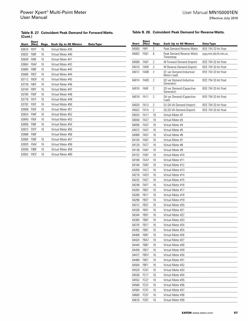
57
User Manual MN150001ENEffective July 2019
Power Xpert® Multi-Point MeterUser Manual
EATON www.eaton.com
Table B. 27. Coincident Peak Demand for Forward Watts. (Cont.)
StartStart (Hex) Regs. Each Up to 60 Meters Data Type
63616 F87F 16 Virtual Meter #39
63632 F88F 16 Virtual Meter #40
63648 F89F 16 Virtual Meter #41
63664 F8AF 16 Virtual Meter #42
63680 F8BF 16 Virtual Meter #43
63696 F8CF 16 Virtual Meter #44
63712 F8DF 16 Virtual Meter #45
63728 F8EF 16 Virtual Meter #46
63744 F8FF 16 Virtual Meter #47
63760 F90F 16 Virtual Meter #48
63776 F91F 16 Virtual Meter #49
63792 F92F 16 Virtual Meter #50
63808 F93F 16 Virtual Meter #51
63824 F94F 16 Virtual Meter #52
63840 F95F 16 Virtual Meter #53
63856 F96F 16 Virtual Meter #54
63872 F97F 16 Virtual Meter #55
63888 F98F 16 Virtual Meter #56
63904 F99F 16 Virtual Meter #57
63920 F9AF 16 Virtual Meter #58
63936 F9BF 16 Virtual Meter #59
63952 F9CF 16 Virtual Meter #60
Table B. 28. Coincident Peak Demand for Reverse Watts. (Cont.)
StartStart (Hex) Regs. Each Up to 60 Meters Data Type
64000 F9FF 2 Peak Demand Reverse Watts IEEE 754 32-bit float
64002 FA01 6 Peak Demand Reverse Watts Timestamp
yyyy,mm,dd,hh,mm,ss
64008 FA07 2 W Forward Demand (Import) IEEE 754 32-bit float
64010 FA09 2 W Reverse Demand (Export) IEEE 754 32-bit float
64012 FA0B 2 Q1 var Demand (Inductive/Motor Load)
IEEE 754 32-bit float
64014 FA0D 2 Q2 var Demand (Inductive Generator)
IEEE 754 32-bit float
64016 FA0F 2 Q3 var Demand (Capacitive Generator)
IEEE 754 32-bit float
64018 FA11 2 Q4 var Demand (Capacitive Load)
IEEE 754 32-bit float
64020 FA13 2 Q1,Q4 VA Demand (Import) IEEE 754 32-bit float
64022 FA15 2 Q2,Q3 VA Demand (Export) IEEE 754 32-bit float
64024 FA17 16 Virtual Meter #2
64040 FA27 16 Virtual Meter #3
64056 FA37 16 Virtual Meter #4
64072 FA47 16 Virtual Meter #5
64088 FA57 16 Virtual Meter #6
64104 FA67 16 Virtual Meter #7
64120 FA77 16 Virtual Meter #8
64136 FA87 16 Virtual Meter #9
64152 FA97 16 Virtual Meter #10
64168 FAA7 16 Virtual Meter #11
64184 FAB7 16 Virtual Meter #12
64200 FAC7 16 Virtual Meter #13
64216 FAD7 16 Virtual Meter #14
64232 FAE7 16 Virtual Meter #15
64248 FAF7 16 Virtual Meter #16
64264 FB07 16 Virtual Meter #17
64280 FB17 16 Virtual Meter #18
64296 FB27 16 Virtual Meter #19
64312 FB37 16 Virtual Meter #20
64328 FB47 16 Virtual Meter #21
64344 FB57 16 Virtual Meter #22
64360 FB67 16 Virtual Meter #23
64376 FB77 16 Virtual Meter #24
64392 FB87 16 Virtual Meter #25
64408 FB97 16 Virtual Meter #26
64424 FBA7 16 Virtual Meter #27
64440 FBB7 16 Virtual Meter #28
64456 FBC7 16 Virtual Meter #29
64472 FBD7 16 Virtual Meter #30
64488 FBE7 16 Virtual Meter #31
64504 FBF7 16 Virtual Meter #32
64520 FC07 16 Virtual Meter #33
64536 FC17 16 Virtual Meter #34
64552 FC27 16 Virtual Meter #35
64568 FC37 16 Virtual Meter #36
64584 FC47 16 Virtual Meter #37
64600 FC57 16 Virtual Meter #38
64616 FC67 16 Virtual Meter #39

58
User Manual MN150001ENEffective July 2019
Power Xpert® Multi-Point MeterUser Manual
EATON www.eaton.com
Table B. 28. Coincident Peak Demand for Reverse Watts. (Cont.)
StartStart (Hex) Regs. Each Up to 60 Meters Data Type
64632 FC77 16 Virtual Meter #40
64648 FC87 16 Virtual Meter #41
64664 FC97 16 Virtual Meter #42
64680 FCA7 16 Virtual Meter #43
64696 FCB7 16 Virtual Meter #44
64712 FCC7 16 Virtual Meter #45
64728 FCD7 16 Virtual Meter #46
64744 FCE7 16 Virtual Meter #47
64760 FCF7 16 Virtual Meter #48
64776 FD07 16 Virtual Meter #49
64792 FD17 16 Virtual Meter #50
64808 FD27 16 Virtual Meter #51
64824 FD37 16 Virtual Meter #52
64840 FD47 16 Virtual Meter #53
64856 FD57 16 Virtual Meter #54
64872 FD67 16 Virtual Meter #55
64888 FD77 16 Virtual Meter #56
64904 FD87 16 Virtual Meter #57
64920 FD97 16 Virtual Meter #58
64936 FDA7 16 Virtual Meter #59
64952 FDB7 16 Virtual Meter #60
64968 FDC7 16 Virtual Meter #61
Table B. 29. Event Push-Down Lists of Most Recent 20 Events.
StartStart (Hex) Regs. Description Data Type
10010 2719 1 Event Count/Index 32-bit unsigned integer
10020 2723 1 EventID [Most Recent Event] Uint32
10021 2724 6 EventTime Date (yyyy,mm,dd,hh,mm,ms)
10027 272A 6 Clear/Reset Time Date (yyyy,mm,dd,hh,mm,ms)
10033 2730 16 ASCII String (Null terMin.ated)
32 Char
10049 2740 29 2nd Oldest Event
10078 275D 29 3rd Oldest Event
10107 277A 29 4th Oldest Event
10136 2797 29 5th Oldest Event
10165 27B4 29 6th Oldest Event
10194 27D1 29 7th Oldest Event
10223 27EE 29 8th Oldest Event
10252 280B 29 9th Oldest Event
10281 2828 29 10th Oldest Event
10310 2845 29 11th Oldest Event
10339 2862 29 12th Oldest Event
10368 287F 29 13th Oldest Event
10397 289C 29 14th Oldest Event
10426 28B9 29 15th Oldest Event
10455 28D6 29 16th Oldest Event
10484 28F3 29 17th Oldest Event
10513 2910 29 18th Oldest Event
10542 292D 29 19th Oldest Event
10571 294A 29 20th Oldest Event
10600 2967 1 EventID [Most Recent Event] Uint16
10601 2968 6 EventTime Date (yyyy,mm,dd,hh,mm,ms)
10607 296E 6 Clear/Reset Time Date (yyyy,mm,dd,hh,mm,ms)
10613 2974 1 Cause of Event Enumeration
10614 2975 2 Value Related to Event Type IEEE 754 32-bit float or 32-bit integer
10616 2977 16 2nd Event
10632 2987 16 3rd Event
10648 2997 16 4th Event
10664 29A7 16 5th Event
10680 29B7 16 6th Event
10696 29C7 16 7th Event
10712 29D7 16 8th Event
10728 29E7 16 9th Event
10744 29F7 16 10th Event
10760 2A07 16 11th Event
10776 2A17 16 12th Event
10792 2A27 16 13th Event
10808 2A37 16 14th Event
10824 2A47 16 15th Event
10840 2A57 16 16th Event
10856 2A67 16 17th Event
10872 2A77 16 18th Event
10888 2A87 16 19th Event
10904 2A97 16 20th Event
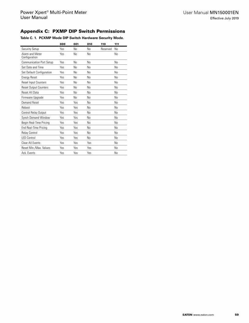
59
User Manual MN150001ENEffective July 2019
Power Xpert® Multi-Point MeterUser Manual
EATON www.eaton.com
Appendix C: PXMP DIP Switch PermissionsTable C. 1. PCXMP Mode DIP Switch Hardware Security Mode.
000 001 010 110 111
Security Setup Yes No No Reserved No
Alarm and Meter Configuration
Yes No No No
Communication Port Setup Yes No No No
Set Date and Time Yes No No No
Set Default Configuration Yes No No No
Energy Reset Yes No No No
Reset Input Counters Yes No No No
Reset Output Counters Yes No No No
Reset All Data Yes No No No
Firmware Upgrade Yes No No No
Demand Reset Yes Yes No No
Reboot Yes Yes No No
Control Relay Output Yes Yes No No
Synch Demand Window Yes Yes No No
Begin Real-Time Pricing Yes Yes No No
End Real-Time Pricing Yes Yes No No
Relay Control Yes Yes No No
LED Control Yes Yes No No
Clear All Events Yes Yes Yes No
Reset Min./Max. Values Yes Yes Yes No
Ack. Events Yes Yes Yes No

60
User Manual MN150001ENEffective July 2019
Power Xpert® Multi-Point MeterUser Manual
EATON www.eaton.com
Appendix D: Glossary, and AcronymsD.1 Glossary
D.1.1 Hardware System Components
Module (Plug-in Module)e: An optional module that can be plugged into the PXMP Meter .
Plug-in Slote: The area on a Meter Base that can house a single plug-in module . This is enumerated from one to ten .
Power Xpert Multi-Point Meter (PXMP)e: The hardware system that includes a Meter Base, Meter Modules, Pulse Input Modules, Digital Output Modules, an Energy Portal Module plus related accessories .
Power Xpert Multi-Point Digital Output Module (Digital Output Module - PXMP-DOM)e: An optional module that contains up to eight discrete outputs, controlled manually or by alarms .
Power Xpert Multi-Point Energy Portal Module (Energy Portal Module - PXMP-EPM)e: A plug-in module that hosts web pages via TCP/IP . Optionally, this module can support a modem with –M suffix on catalog number .
Power Xpert Multi-Point Meter Base (Meter Base - PXMP-MB)e: The base of the PXMP Meter with ten slots for plug-in modules . The base has integral external circuit groups and user interfaces including three discrete inputs and one solid sate relay discrete output, two serial Com . ports, power supply, and mains voltage monitoring . Two versions exist: one is 3-phase the other single-phase with –AB suffix on catalog number (PXMP-MB-AB) .
otee:N The PXMP-MB can be used on 3-Phase, 2-Phase, and single-phase applications . The PXMP-MB-AB can ONLY be used on single-phase applica-tions .
Power Xpert Multi-Point Meter Module (Meter Module - PXMP-MM)e: A plug-in module that has six current channels and comes in six variants with three versions of CT sensor interface 10 mA, 100 mA, or 333 mV and then modulated into two groups for 3-phase or single-phase applications (–AB catalog suffix) .
Power Xpert Multi-Point Pulse Input Module (Pulse Input Module - PXMP-PIM)e: An optional module that contains up to eight pulse inputs .
D.1.2 Hardware Accessories
CSXXXe: Eaton 10 mA Current Sensors with 10 mA max . secondary outputs . These sensors have an internal clamp circuit and ID/tamper circuit and are compatible with the PXMP-MM10MA Meter Modules . These sensors have an integral 48 in . (1 .22 m) yellow secondary cable . These current transformer sensors are qualified as double/reinforced insulation, 600V, CAT III .
Display Cablee: 72 in . (1 .83 m) cable (67A2124H02) included with the PXMP-Display (PXMP-DISP-6-XV) to connect the display to the DB9 of the PXMP Meter Base (PXMP-MB) .
Third Party 333 mV Current Sensorse: Third party current load sen-sors with a 333 mV maximum secondary output (burden is internal to sensor) and compatible with PXMP-IM333MV Interface Module and PXMP-MM333MV Meter Modules . These current transformer sensors must provide double/reinforced insulation and be rated for 600V, CATIII .
PSG60Ee: Eaton PSG series 24 Vdc Output Power Supply . This is an External DIN rail mounted supply rated for 50 W 24 Vdc output and 100-240 Vac (+/-10%) rated input 50/60 Hz to power the PXMP Meter Base and PXMP-PIM/PXMP-DOM or PXMP-MB external cir-cuit groups . Alternate power supplies may be required depending on the mains input rating, the total load, and the ambient tempera-ture . See Eaton PSG family for other wattage output and mains input range/type .
PXMP-CSXXXe: Eaton 100 mA Current Sensors with 100 mA max . secondary outputs . These sensors have an internal clamp circuit with an LED alarm indicator, ID/tamper circuit, and sensor LED loca-tor indicator built in . They are compatible with the PXMP-MM100MA Meter Modules and the separate PXMP-SCXX Sensor Cables . These current transformer sensors are qualified as double/reinforced insula-tion, 600V, CAT III .
PXMP-DISP-6-XV (PXMP-Display)e: Eaton XV-102 5 .7-inch color touch-screen interface (XV-102-H4-57TVRL -10) preloaded and opti-mized for use with the PXMP-MB .
PXMP-IM100MAe: (Interface Module)e: Generic 100 mA Interface Module for connecting a generic 100 mA current sensor to an Eaton PXMP-SCXX sensor cable and then to a PXMP-MM100MA Meter Module . This module supplies a terminal block for the secondary 100 mA current sensor, Clamp Circuit with Alarm LED indicator, ID/tamper detection circuit, locator LED indicator, 2 x 2 PXMP-SC Sensor Cable connector, and a cover .
PXMP-IM333MV (Interface Module)e: 333 mV Interface Module for connecting a Third Party 333 mV current sensor to an Eaton PXMP-SCXX sensor cable and then to a PXMP-MM333MV Meter Module .This module supplies a terminal block for the secondary 333 mV cur-rent sensor, ID/tamper detection circuit, locator LED indicator, 2 x 2 PXMP-SC Sensor Cable connector, and a cover
PXMP-SCXX/SCEXXe: Sensor Cable and Sensor Cables Extension in various lengths . These cables are compatible with PXMP-MM Meter Modules, PXMP-CSXXX current sensors, and PXMP-IM Interface Modules .
D.1.3 Hardware Sub-circuit Level
2 x 2 Pluge: 2 x 2 square 4-pin mating plug .
2 x 2 Receptaclee: 2 x 2 square 4-pin mating receptacle .
Com, 1 and 2e: RS-485 Serial ports on the PXMP-MB for use as Modbus RTU slaves .
Configuration Porte: A slave USB 2 .0 on the PXMP-MB for use as a Modbus RTU slave
Current Channele: A power load current sensor monitoring channel attached directly to the PXMP-MMs which ultimately forward data to the STM32 .
Voltage Channele: A power system mains voltage monitoring chan-nel attached to the PXMP-MB and distributed internally to all PXMP-MMs, which ultimately forwards data to the STM32 MCU .
D.1.4 User Interface Tools
Configuration APIe: Special Modbus protocol that the PXMP Configuration Software and PXMP-EPM use to talk to the PXMP-MB .
E-Allocation Softwaree: Software that reads from the PXMP-EPM to compile bills .
Energy Portal Web Interfacee: Web pages on the PXMP-EPM, espe-cially including a Java Applet .
Offline Configuratione: The concept of opening and editing a con-figuration file stored locally .
PXMP Configuration Softwaree: External software that programs the PXMP Meter via Modbus to the PXMP-MB .

61
User Manual MN150001ENEffective July 2019
Power Xpert® Multi-Point MeterUser Manual
EATON www.eaton.com
D.1.5 Application Constructs
Configuration Constructs
Aggregate Metere: Functions like a Sub-meter . If a Main Meter is selected, this refers to the Main Meter . If not, this refers to the sum of all other Sub-meters .
Alarmse: Triggers that can cause events . Created using the PXMP Configuration Software .
Event Detailse: A list of events caused by alarms . The PXMP Meter Base generates the Event Details and holds 20 . The PXMP Energy Portal Module keeps a longer copy of the Event Details .
Event Loge: A large list of strings that describe every event that has occurred . It is held on the PXMP Meter Base .
Main Metere: A Sub-meter that is selected to represent the sum of all other Sub-meters . The Main Meter can be disabled if no Sub-meter is selected .
Profile Datae: A time-value data set that is generated by and held on the PXMP Meter Base . The PXMP Energy Portal Module reads and keeps a copy .
Pulse Metere: A pulse counter associated with an PXMP Pulse Input Module .
Real-time Datae: Values that are updated on the PXMP Meter Base and polled by the PXMP Energy Portal Module to create the Trend Data .
Sub-metere: A group of channels, defined on the PXMP Meter Base .
System Loge: A large list strings that describe any system notifica-tions . It is generated and held by the PXMP Meter Base .
Energy Portal Web Interface Constructs
Facility Manager (Admin User)e: A User of the Energy Portal GUI that has administrative rights to change settings on the PXMP Energy Portal Module .
Tenant Groupe: A group of Sub-meters and Pulse Meters, defined only on the PXMP Energy Portal Module .
Tenant Usere: A user of the Energy Portal GUI that has guest access to the PXMP Energy Portal Module . Access only includes one Tenant Group .
Trend Datae: A time-value data set that is generated by the PXMP Energy Portal Module from the Real-time Data on the PXMP Meter Base .
D.2 Power Xpert Multi-Point Meter Acronyms
Ae: amp, ampere
ANSIe: American National Standards Institute .
AWGe: American Wire Gauge
°Ce: Degrees Celsius
CANe: Canada, Canadian
CNLe: Canadian National Laboratory
COM 1 and COM 2e: RS485 Serial Communications Port
°Fe: Degrees Fahrenheit
fte: Foot
Hze: Hertz
IECe: International Electrotechnical Commission
in.e: Inch
Ke: Kilo
Kohme: Kilo Ohm
kVe: Kilo Volt
LEDe: Light Emitting Diode
Me: Mega
me: Meter
mAe: Milliamp
mme: Millimeter
Mohme: Mega Ohm
mVe: Millivolt
PSG60Ee: Eaton PSG Series 27 Vdc Output Power Supply
PXMP Metere: Power Xpert Multi-Point Meter .
PXMPe: Power Xpert Multi-Point .
PXMP-CSXXXe: Eaton 100 mA Current Sensors
PXMP-DISP-6-XVe: (PXMP-Display) Eaton XV-102 5 .7-inch color touch screen optimized for use with the PXMP-MB
PXMP-DOMe: Power Xpert Multi-Point Digital Output Module
PXMP-EPMe: Power Xpert Multi-Point Energy Portal Module
PXMP-IM333MVe: 333 mV Interface Module
PXMP-MBe: Power Xpert Multi-Point Meter Base
PXMP-MMe: Power Xpert Multi-Point Meter Module
PXMP-PIMe: Power Xpert Multi-Point Pulse Input Module
PXMP-SCEXXe: Sensor Cable Extension
PXMP-SCXXe: Sensor Cable
ULe: Underwriters Laboratories
Ve: Volt
Vac (VAC)e: Voltage Alternating Current
Vdc (VDC)e: Voltage Direct Current
62
User Manual MN150001ENEffective July 2019
Power Xpert® Multi-Point MeterUser Manual
EATON www.eaton.com
D.3 External Circuit Groups
Com 1e: An RS485 serial communications port that supports Slave Modbus RTU protocol and using PXMP Meter Base terminals 7-10 .
Com 2e: An RS485 serial communications port that supports Slave Modbus RTU protocol and using PXMP Meter Base terminals 11-14 .
Configuration Porte: A slave USB 2 .0 serial port supporting Modbus RTU protocol and located top right of the PXMP Meter Base .
Digital Outputse: Solid State Relay outputs on the PXMP Digital Output Module and tied to application alarms of the PXMP Meter .
Energy Portal Configuration Porte: A 10/100 base T, RJ45 Ethernet Local configuration port restricted to address 192 .168 .1 .1 or 10 .0 .0 .1 for direct connection to a notebook computer for configuration pur-poses and not to be used on a LAN/WAN .
Energy Portal LAN/WAN Porte: A 10/100 base T, RJ45 Ethernet Port for direct connection to a notebook computer for LAN/WAN commu-nication purposes .
Energy Portal Modem Porte: An RJ11 connection to land line tele-phone system .
Meter Base Digital Input (MBDI)e: A group of three Discrete Inputs for reading the status of external dry contacts (externally wetted) for application control purposes, common on Terminal 3, Inputs 1-3 on terminals 4-6 .
Meter Base Digital Output (MBDO)e: A solid-state relay for control of external loads (externally wetted) to represent control or energy pulse output located on terminals 1 or 2 of the PXMP Meter Base .
Meter Current Sensor Inpute: An external current sensor instrument transformer load monitoring circuit that connects to a PXMP Meter Module through a 2 x 2 receptacle .
Meter Voltage Inputse: The mains metering voltage input associated with all of the current loads being monitored and using PXMP Meter Base terminals 18-21 .
Mode Setup Switchese: Switches on the PXMP Meter Base . Located at the top right of the Meter Base under a sealable cover, these switches can set the application mode of the PXMP Meter .
Power Source (PS) Inpute: 24 Vdc input power source for the PXMP Meter Base using terminals 15-17 . Not for direct connection to a CAT III power bus . Use a dedicated local 24VDC source for PXMP use only .
Protective Earth Stude: An electrical connection on the PXMP Meter Base to bond the PXMP Meter to the system safety ground .
Pulse 24 Vdc Powere: A two position terminal plug on the PXMP Pulse Input Module to source power from an external 24 Vdc supply to drive the status of pulse inputs . Not for direct connection to a CAT III power bus . Use a dedicated local 24VDC source for PXMP use only .
Pulse Inpute: A pulse input of the PXMP Pulse Input Module used to read dry contact pulses from third party pulse sensors for energy integration purposes .
Slave Address Switchese: Rotary Switches on the top right of the PXMP Meter Base . These are used to set the PXMP Meter’s Modbus Slave Address for Com 1 & 2 .

63
User Manual MN150001ENEffective July 2019
Power Xpert® Multi-Point MeterUser Manual
EATON www.eaton.com
Index
Numerics
0 .5% accuracy 5, 12, 131 A/5 A CT 4, 51 A/5 A CT secondary 51 pole loads 21W - Meter Base digital Inputs 52 .2 K ohm input impedance 162 pole loads 22-pole meter 4, 262-position 16, 402 W - Meter Base digital Output 52 W - Per Pulse Input Module 5, 232 x 2 receptacle 10, 15, 25, 26, 623-PH 3-Wire Delta (Grounded) 73-PH 4-Wire Wye 73-phase 2, 4, 6, 7, 11, 16, 23, 26, 603-Phase 4-Wire Service 10, 25, 33, 363-phase 480 VL:L rated Wye mains supplies 6, 233-phase commercial 23-phase industrial 23-phase loads 11, 163-Phase Metering 113-phase tenants 163-phase Wye 73 pole loads 23-pole meter 43 W - PXMP Display 5, 234-position terminal plug 5, 134-position terminal plug socket 134-position white 2 x 2 plug 155 A CT 12, 256-inch Color Touch-Screen Interface 310 mA 3, 4, 5, 8, 11, 12, 16, 24, 25, 26, 40, 41, 42, 43, 6010 mA Meter Modules 4, 2410 mA output 310 mA per closed input 5, 1610 mA sensor cables 1210 mA sensors 4, 2415 .4 W - Per Digital Output Module 515 W - Meter Base 5, 2320 Hz square wave 5, 1520 W worst case for ten cards 5, 2324 Vdc (+/- 20%) sources 424 Vdc Input 824 Vdc Power Source 524 Vdc power supply 3, 4, 5, 8, 9, 16, 22, 2324 V power supply 1624 V power supply terminal 16100 mA 3, 4, 5, 8, 11, 12, 13, 14, 24, 26, 41, 43, 60, 61100 mA current sensors 4, 5, 12100 mA maximum rated secondary current sensors 24100 mA Max . Secondary Outputs 14100 mA output sensors 3100 mA sensors 4, 13, 24
100 mA sensors connect 4120/240 V, Single-Phase 3-Wire Service 7154 W worst case for ten cards 5, 23333 mV 3, 4, 5, 8, 11, 12, 24, 26, 27, 41, 60, 61333 mV maximum rated secondary current sensors 24333 mV Meter Modules 4, 24333 mV output sensors 4333 mV sensors 4, 24333 mV sensors connect 4347VL:N & 600VL:L 4480VL:G & L:L 4
A
A1 7, 10, 12, 25, 43A1, B1 7, 12A1, B1, A2, B2, and A3, B3 7A2 7, 10, 12, 25A2, B2 7, 12A3 7, 10, 12, 25A3, B3 7, 12accuracy 4, 5, 12, 13, 15, 26accuracy issues 5A Connection 8adapter module 15advanced tenant metering functionality 8aggregate sum of the tenant meters 9air meters 2, 6alarm conditions 5, 16Alarm LED 5, 60ambient temperature 4, 5, 23, 60apartment complex 15automatic control 2, 6A (V1) 8, 41, 43A voltage 12
B
B1 7, 10, 12B2 7, 10, 12B3 7, 10, 12Baud Rate 39B Connection 8blue LED 13, 15branch circuit 2building automation systems . 5, 16burden issues 5, 15B voltage 12
C
CAUTION 6C Connection 8chassis ground 8, 41circuits 2, 4, 6, 23, 40, 42circuits to be metered 2, 6clamp alarm 5, 12Clamp Alarm LED 5
64
User Manual MN150001ENEffective July 2019
Power Xpert® Multi-Point MeterUser Manual
EATON www.eaton.com
clamp circuit 13, 60Cleaning 1, 11, 39closed input 5, 16Com 1 5, 9, 37, 40, 41, 43, 62Com 2 5, 9, 37, 41, 43, 62COM Health 9, 10, 11, 16, 41, 42Com LED 11commissioning 9, 11, 15, 16, 17, 18commissioning mode 15commissioning purposes 16commissioning test 11Common 29, 37, 39, 40, 43common terminals 8, 11, 29, 37, 38, 39, 40, 41, 42, 43, 62communication ports 9, 37Communications Rotary Address Switches 9Component Overview 1, 4Coms Ports 9COM Status 16Configuration Ports 9configuration process 5, 17Contact closed 16Contact open 16Cover . 8CPT 6, 23CS005 3, 4, 5, 12, 13, 24, 25, 26, 36CS050 3, 12CS125 3, 12, 14, 25, 26CS200 3, 12, 26CS400 3, 12, 13, 14, 26CSXXX 10 mA 4, 5, 12, 26CSXXX 10 mA Current Sensors 5CT secondary wires 15current flowing 12, 16current is flowing out 11Current loop output sensors 4Current Sensing 4current sensor 3, 4, 5, 9, 10, 11, 12, 13, 15, 19, 24, 25, 26,
27, 33, 41, 60, 61, 62current sensor circuit 12current sensor connections 10Current Sensor Dimensions 13current sensor input 9, 10, 11, 12current sensor (instrument transformers) outputs 4current sensor load direction 12Current Sensor Module 5 Amps 3Current Sensor Module 50 Amps 3Current Sensor Module 125 Amps 3Current Sensor Module 200 Amps 3Current Sensor Module 400 Amps 3current sensor secondary type 11current sensor wires 15current transformers 4, 24, 26, 41C (V3) 8, 41, 43
D
Data- (D-) terminals 37Data+ (D+) terminals 37Delta applications 4Delta LED 9Delta system 7, 8demand synch pulse 9de-rating 6, 23Digital (Discrete) I/O External Circuit Group 4digital inputs 9, 16, 23Digital Output 1, 3, 4, 5, 6, 8, 9, 16, 19, 20, 23, 29, 41, 43,
60, 61, 62Digital Output Module 3, 4, 5, 6, 8, 16, 19, 23, 29, 41, 60,
61, 62digital status inputs 9Dimensions 13, 15, 21DIN 22DIN rail 8, 22, 23, 60Diode 6, 43, 61direction of current flow 11Direct Mains Voltage Monitoring 4direct voltage metering 4Disconnect 22, 26dry contact 5, 16, 23, 40, 62dry contact closed 5, 23
E
earth ground 6, 8, 11, 16, 17electrical power distribution systems 6ELECTRICAL WARNING 6electricity 2, 6electric meters 2, 6embedded Web server 6EMC performance 8, 41enclosure 1, 4, 8, 11, 19, 20, 21, 22, 23energy measurement 5, 15Energy Portal Module 1, 2, 3, 5, 6, 8, 10, 16, 17, 19, 20, 42,
60, 61environmental specification ranges 4error base 12Ethernet 2, 5, 6, 8, 16, 37, 42, 43, 62Ethernet RJ-45 configuration port 16exciting voltage 5, 16extension cables 5external circuit 4, 6, 16, 23, 60external circuit groups 1, 4, 6, 16, 23, 60, 62external power source 5, 16
F
feeder 2female housing 15floating Delta applications 4front facing LEDs 16FTP 2, 6Fuse 6, 41

65
User Manual MN150001ENEffective July 2019
Power Xpert® Multi-Point MeterUser Manual
EATON www.eaton.com
G
gas 2, 5, 6, 15, 16gas meter 2, 5, 6, 15, 16generator 11, 24, 47, 48, 49green LED 11, 15, 24ground 6, 8, 11, 16, 17, 22, 23, 40, 41, 62Ground Connection 8grounded Delta applications 4Grounding 8
H
Hardware Overview 1, 6hard wired 9, 12hazardous circuits 4hazardous terminal access 8Health LED 9, 11high density metering applications 2, 6HMIVUC06CUNB 27HTTP 2, 6
I
independent common 37indicate alarm conditions 5, 16industry standard current sensors 4input circuit 1, 2, 3, 4, 5, 6, 7, 8, 9, 15, 16, 19, 20, 23, 28,
29, 40, 41, 42, 43, 44, 51, 52, 53, 54, 60, 61, 62input impedance 5, 16Inputs 3, 5, 8, 9, 10, 23, 29, 30, 40, 41, 42, 43, 44, 51, 52,
53, 54, 62input voltage ratings 15insulated load cables . 4insulated wire sheath 26interface board 15, 27Interface Modules 3, 5, 15, 24, 26, 27, 41, 60, 61interferences 22internal clamp 12, 13, 60internal clamp circuit 13, 60internal dial up telephone modem 5, 16internal environment 4internal logic 5interposing 2, 4, 5, 12, 16, 24, 25Interposing current transformers 4interposing load sensors 2Interposing Potential 4, 7interposing potential transformer 4interposing solid state relay 5, 16interval by interval demand recording 19interval demand data 4, 19interval demand recording 4, 19inversion 15isolation 4, 5, 6, 23, 40, 41, 43isolation barrier 6, 23, 41isolation from mains 5, 23
J
JAVA application 5, 17
K
kW Forward Demand 50, 54, 56, 57kW Reverse Demand 4, 50, 54
L
LAN 5, 16, 37, 42, 62LAN/WAN RJ-45 Ethernet jack 16LAN/WAN RJ-45 Ethernet port 5LED A 1, 2, 4, 5, 6, 7, 8, 9, 10, 11, 12, 14, 15, 16, 23, 24,
25, 26, 27, 38, 39, 40, 41, 43, 44, 45, 60, 61, 62, 70LED B 1, 5, 7, 8, 9, 10, 12, 16, 17, 37, 40, 41, 43, 44, 45, 46,
48, 49, 50, 51, 52, 53, 54, 55, 56, 57, 58, 59LED C 1, 7, 8, 9, 10, 12, 41, 43, 45, 60, 61, 62LED indicators 9, 24, 41LED locator circuitry 24LEDs 5, 9, 10, 11, 12, 13, 15, 16, 24, 26, 39, 40, 42, 44LED status 16load cables 4, 15, 24load circuit 11, 15, 24load circuit pairing 11load conductors 4, 11load current 9, 12, 13, 24, 40, 60Load Current measurements 4load monitoring 2, 62Load Orientation 12Load Power LEDs 15load side 11local display 2, 6locator circuit 15Locator LEDs 5, 12lockout 22low voltage 2
M
mains 4, 5, 6, 23, 39, 41, 60, 62mains applications 23mains rating 4mains source 23Maintenance 1, 11, 39male plug 15maximum anticipated ambient temperature 5, 23Maximum length 5maximum load 5, 16, 41maximum possible 24 Vdc loads 5, 23maximum voltage ratings 4metal slot cover 7Meter Base assembly 6, 7, 8, 9, 10, 11, 12, 16, 17, 18, 19,
20, 23, 37Meter Base logic 16meter calibration system 11metered data 2, 6

66
User Manual MN150001ENEffective July 2019
Power Xpert® Multi-Point MeterUser Manual
EATON www.eaton.com
metering 2, 4, 5, 6, 7, 8, 9, 11, 12, 16, 18, 24, 26, 27, 39, 41, 62
metering applications 2, 6, 11metering calculations 11metering channels 2, 6metering errors 9, 12metering system 2, 6meter modules 2, 3, 4, 5, 6, 7, 8, 9, 10, 11, 12, 15, 16, 19,
24, 25, 39, 41, 60Meter Module w/6 10 mA inputs 11, 12Meter Module w/6 10 mA inputs - 1 PH 3W 12Meter Module w/6 100 mA inputs 11, 12Meter Module w/6 100 mA inputs - 1 PH 3W 12Meter Module w/6 333 mV inputs 11, 12meter readings 5, 27Meter Voltage Input 8, 9Meter Voltage Input connector 9minimum components 19Modbus 1, 2, 5, 6, 9, 16, 17, 37, 39, 40, 42, 44, 52, 60, 62Modbus Map 37Modbus Masters 9Modbus register map 16Modbus Registers 1, 9Modbus slave ID 37Modbus Slave ports 37Modbus TCP 2, 6, 42Mode DIP 9Mode DIP switches 9modem communications 8mode of 11, 62Mode switches 9Monitor meter values 4motherboard 6, 8Mounting Feet 13Mounting Holes 13Multi-Point Meter 1, 2, 4, 6, 7, 11, 12, 17, 19, 60, 61
N
N Connection 8no current flowing 16noise immunity 4, 37, 40noise immunity advantages 4non-volatile memory 4, 5, 19normal operation 4, 24N (VR) 8, 41, 43N (VR) terminal 8
O
OEM 22Offline configuration 5Online configuration 5open circuit risks 4optimum convection cooling 23optional shield cable connection 8Ordering Information 1, 2Output circuits 23
output external circuit 23Output modules 2, 23output ratings 6, 23outputs 4, 5, 11, 15, 16, 23, 24, 41, 44, 52, 60, 62
P
panel boards 2Parity 39performance specification 12Phase A 10, 12, 25, 45Phase A1 10Phase A2 10Phase A3 10phase application 11phase assignment label 10phase assignments 10Phase B 10, 12, 45Phase B1 10Phase B2 10Phase B3 10Phase C 10, 12, 45phase current assignments 12phase voltage 9, 10potential transformers 2power distribution 2, 6, 11Power LED 9, 11power requirements 4power supply 4, 5, 8, 9, 16, 23, 60power supply input 4power supply terminal 8, 16power system metering data 5, 27power systems 2Power Xpert 1, 2, 4, 6, 7, 11, 12, 17, 19, 43, 60, 61primary current ratings 4primary load drive 12product overview 1, 2Product Specifications 1, 24proper supply 4Protective Earth Ground 6protective earth (PE) ground 8protective earth safety ground 22, 23PSG60E 3, 6, 19, 23, 60, 61PSG60F 6, 23PSG120E 3, 6, 23PSG120F 6, 23PSG240E 3, 6, 23PSG240F 6, 23PSG480E 6, 23PSG480F 6, 23PSG E 6, 23pulse counting 16pulsed optical outputs 11Pulse Initiator output 9Pulse Input 1, 2, 3, 4, 5, 6, 8, 15, 16, 19, 20, 23, 28, 29,
42, 43, 60, 61, 62Pulse Input Circuitry 16, 29

67
User Manual MN150001ENEffective July 2019
Power Xpert® Multi-Point MeterUser Manual
EATON www.eaton.com
Pulse Input Module 3, 4, 5, 8, 15, 16, 19, 23, 28, 60, 61, 62
Pulse Input Modules 2, 6, 8, 16, 42, 60Pulse LED 11pulse metering 2, 6Pulse meters 19pulse outputs 15, 16pulse rate 5, 11, 15, 40, 42Pulse type 5pulse type output 15PXMP Configuration Software 1, 5, 9, 11, 13, 15, 17, 18,
19, 26, 27, 37, 39, 60, 61PXMP Configuration Software Manual 5, 17PXMP-CS125-3 3PXMP CS125 Sensor 3PXMP-CS250-3 3PXMP CS250 Sensor 3PXMP-CS400-3 3PXMP CS400 Sensor 3PXMP-CSXX 15PXMP-CSXXX 3, 4, 5, 11, 12, 13, 15, 24, 26, 40, 41, 60, 61PXMP-CSXXX 100 mA 4, 5, 12, 13, 26PXMP-CSXXX 100 mA current sensors 5PXMP Current Sensor Interface Module 3PXMP Digital Output Module 5, 16, 19, 29, 41, 62PXMP-DISP-6 3, 5, 27, 60, 61PXMP-DISP Display 3PXMP-DOM 3, 5, 16, 19, 29, 41, 43, 60, 61PXMP Energy Portal Module 2, 5, 6, 8, 10, 16, 19, 42, 61PXMP-EPM 2, 3, 5, 6, 8, 16, 17, 19, 37, 42, 43, 60, 61PXMP-EPM-M 3, 5, 16PXMP-IM 11, 15, 60PXMP-IM333MV-3 3PXMP-IMxxxxx 5PXMP Load Current measurements 4PXMP-MB 2, 3, 5, 6, 7, 8, 10, 11, 12, 17, 19, 37, 40, 41, 42,
43, 60, 61PXMP-MB-AB 3, 5, 7, 8, 10, 11, 12, 43, 60PXMP-MB-AB CT Inputs label 10PXMP-MB CT inputs label 10PXMP Meter 1, 2, 3, 4, 5, 6, 7, 9, 11, 12, 16, 17, 19, 20, 21,
22, 23, 24, 25, 26, 27, 28, 37, 39, 41, 60, 61, 62PXMP Meter Base 2, 3, 4, 5, 6, 7, 17, 19, 20, 28, 37, 41, 60,
61, 62PXMP Meter Digital Output Module 3PXMP Meter Energy Portal Module 3PXMP Meter Energy Portal Module w/ Modem 3PXMP Meter Modules 2, 4, 5, 6, 7, 11, 19, 41PXMP Meter Pulse Input Module 3PXMP Meter System Power Requirements 4PXMP-MM10MA 3, 5, 11, 12, 24, 41, 43, 60PXMP-MM10MA 10 mA Meter Module 5, 12PXMP-MM10MA-AB 3, 12PXMP-MM100MA 3, 5, 11, 12, 13, 14, 24, 41, 43, 60PXMP-MM100MA 100 mA Meter Module 5, 13PXMP-MM100MA-AB 3, 12PXMP-MM333MV 3, 11, 12, 41, 43
PXMP-MM333MV-AB 3, 12PXMP-MM333MV-AB Meter Module w/6 333 mV inputs -
1 PH 3W 12PXMP-MMs 2, 4, 6, 11, 39, 41, 60PXMP-PIM 3, 5, 6, 15, 16, 19, 43, 60, 61PXMP-PIMs 2, 42PXMP Pulse Input Module 2, 4, 5, 6, 15, 19, 28, 29, 42,
61, 62PXMP-SC 5, 12, 15, 24, 60PXMP-SC4-3 3PXMP-SC6-3 3PXMP-SC8-3 3PXMP-SC12-3 3PXMP-SCE8-3 3PXMP-SCE16-3 3PXMP-SC/SCEXX 5, 15PXMP Sensor Cable, 4 Ft . 3PXMP Sensor Cable, 6 Ft . 3PXMP Sensor Cable, 8 Ft . 3PXMP Sensor Cable, 12 Ft . 3PXMP Sensor Extension Cable, 8 Ft . 3PXMP Sensor Extension Cable,16 Ft . 3PXM-SC/SCE sensor cables 5
Q
Q4 kVAR Demand 4
R
rate alert 9Receive activity 9red LED 11, 13, 15, 24, 41regulations 2remote billing software 2, 6, 16remote control 2, 6residential 2, 7, 11, 12Resistor 6reverse/forward Power LED 11RJ-45 configuration port 5, 16RS485 bus 38RS485 Daisy Chain Connection 38RS485 Master 38RS-485 Modbus 5, 9, 17, 37RS-485 Modbus communications link 17RS-485 Modbus slave communication ports 9RS485 repeater 38RS-485 serial communication ports 37RX LED 9
S
safety code(s) 2safety ground 22, 23, 62safety ground terminal 23safety precautions 1, 2safety standards 2SCX cables 15
68
User Manual MN150001ENEffective July 2019
Power Xpert® Multi-Point MeterUser Manual
EATON www.eaton.com
secondary output 4, 5, 12, 13, 15, 24, 26, 41secondary output current sensors 5secondary output sensors 12, 13, 26secondary output wires 15self-compensated 5, 15Sensor Cable Extension 15, 61Sensor Cable Extensions 3sensor cable(s) 3, 5, 12, 15, 24, 25, 26, 41, 60Sensor Extension Cable 3, 15sensor identification 15sensor input connections 9, 11sensor input connectors 12sensor secondary cable 12, 13sensor secondary output cable 13serial communications session 9Serial Communications Setup 1, 9, 37shield 8, 37, 38, 39, 40, 41shield terminals 37signal integrity 37single-phase 2, 4, 7, 11, 12, 60single-phase 3-wire 11, 12Single-Phase 3-Wire 120/240 9, 32single-phase application(s) 4, 7, 11, 12, 60single-phase loads 11, 16single-phase meter base 7single-phase metering 7single-phase service 7single pole sub-meters 4, 19Slave Modbus RTU protocol 37, 62slave port connectors 37slave USB connector 9slot covers 7SMTP 2, 6SNMP 2, 6solar inverter 11Solid Core 12, 14, 24, 25solid core sensors 2, 4, 6solid state outputs 5, 23solid state relay 5, 16solid-state relay output 9source pulse 5, 16split core sensors 2, 4, 6Standard 3-phase Meter Base 11standard 5 A current transformers 4Standard and Optional Components 3standard Meter Modules 4, 11Star arrangements 38“Star” connections 38state of the input 16Status LED 9steam 2, 5, 6, 15steam meters 2, 6Stop Bits 39strain relief 15, 27Sub-meters 19switch 2, 6, 15, 40switchable intermediate conversion 5, 15
T
tamper detect circuit 5, 12, 13tamper detection 15, 60tamper detection circuit 15, 60“Tee” connections 38telephone connection 2, 6tenant meters 9, 16tenants 2, 6, 15, 16terminal header 8terminal plug 5, 8, 13, 40, 41, 42, 62Termination Resistors (RTs) 38three-pole sub-meters 4threshold triggers 2, 6Touch Screen Display 2, 4, 5, 6, 19, 27, 36transition 16Transmit activity 9troubleshooting 11twisted pair 37, 38twisted pair cable 38Two Data-Wire RS485 Connection 38two-pole sub-meters 4two pulses per tenant 16TX LED 9Type B USB connector 17
U
USB cable 17USB port (Type B) 5User protection 4utilities 5, 15
V
Voltage Input connections 9voltage input connector 11voltage inputs 8, 11, 12Voltage Input Terminal Plug 8voltage terminal inputs 9
W
warning 2, 15, 22, 26water 2, 5, 6, 15, 16water meter(s) 2, 6, 16Web enabled metering 5, 16Wiring Connections 1, 9, 11, 28wiring networks for 120/240 V single-phase 3-wire residen-
tial service 11wiring schematics 9Wizard 5, 17worst case ambient temperature 4worst case power consumption 4Wye/1PH LED 9Wye applications 4

69
User Manual MN150001ENEffective July 2019
Power Xpert® Multi-Point MeterUser Manual
EATON www.eaton.com
X
Y
Z

Eaton Electrical Sector1000 Eaton BoulevardCleveland, OH 44122United States877-ETN-CARE (877-386-2273)Eaton.com
© 2019 EatonAll Rights ReservedPrinted in USAPublication No. MN150001EN / TBG001042July 2019
Eaton is a registered trademark.
All other trademarks are property of their respective owners.
User Manual MN150001ENEffective July 2019
Power Xpert® Multi-Point MeterUser Manual
This user manual is published solely for information purposes and should not be considered all-inclusive . If further information is required, you should consult an authorized Eaton sales representa-tive .
The sale of the product shown in this literature is subject to the terms and conditions outlined in appropriate Eaton selling policies or other contractual agreement between the parties . This literature is not intended to and does not enlarge or add to any such contract . The sole source governing the rights and remedies of any purchaser of this equipment is the contract between the purchaser and Eaton .
NO WARRANTIES, EXPRESSED OR IMPLIED, INCLUDING WARRANTIES OF FITNESS FOR A PARTICULAR PURPOSE OR MERCHANTABILITY, OR WARRANTIES ARISING FROM COURSE OF DEALING OR USAGE OF TRADE, ARE MADE REGARDING THE INFORMATION, RECOMMENDATIONS, AND DESCRIPTIONS CONTAINED HEREIN. In no event will Eaton be responsible to the purchaser or user in contract, in tort (including negligence), strict liability or otherwise for any special, indirect, incidental or conse-quential damage or loss whatsoever, including but not limited to damage or loss of use of equipment, plant or power system, cost of capital, loss of power, additional expenses in the use of existing power facilities, or claims against the purchaser or user by its cus-tomers resulting from the use of the information, recommendations and description contained herein .