user manual - eatonpub/@eatonca/... · power xpert c445 global motor management relay user manual...
TRANSCRIPT
Power Xpert C445 Global Motor Management Relay
User ManualEffective September 2015
New Information


Power Xpert C445 Global Motor Management Relay
Disclaimer of Warranties and Limitation of Liability
The information, recommendations, descriptions and safety notations in this document are based on Eaton’s experience and judgment and may not cover all contingencies. If further information is required, an Eaton sales office should be consulted. Sale of the product shown in this literature is subject to the terms and conditions outlined in appropriate Eaton selling policies or other contractual agreement between Eaton and the purchaser.
THERE ARE NO UNDERSTANDINGS, AGREEMENTS, WARRANTIES, EXPRESSED OR IMPLIED, INCLUDING WARRANTIES OF FITNESS FOR A PARTICULAR PURPOSE OR MERCHANTABILITY, OTHER THAN THOSE SPECIFICALLY SET OUT IN ANY EXISTING CONTRACT BETWEEN THE PARTIES. ANY SUCH CONTRACT STATES THE ENTIRE OBLIGATION OF EATON. THE CONTENTS OF THIS DOCUMENT SHALL NOT BECOME PART OF OR MODIFY ANY CONTRACT BETWEEN THE PARTIES.
In no event will Eaton be responsible to the purchaser or user in contract, in tort (including negligence), strict liability or otherwise for any special, indirect, incidental or consequential damage or loss whatsoever, including but not limited to damage or loss of use of equipment, plant or power system, cost of capital, loss of power, additional expenses in the use of existing power facilities, or claims against the purchaser or user by its customers resulting from the use of the information, recommendations and descriptions contained herein. The information contained in this manual is subject to change without notice.
Cover Photo: Eaton Power Xpert® C445 global motor management relay
Power Xpert C445 Global Motor Management Relay MN042003EN—September 2015 www.eaton.com i
Power Xpert C445 Global Motor Management Relay
Support Services
The goal of Eaton is to ensure your greatest possible satisfaction with the operation of our products. We are dedicated to providing fast, friendly, and accurate assistance. That is why we offer you so many ways to get the support you need. Whether it is by phone, fax, or email, you can access Eaton’s support information 24 hours a day, seven days a week.Our wide range of services is listed below.You should contact your local distributor for product pricing, availability, ordering, expediting, and repairs.
Website Use the Eaton website to find product information. You can also find information on local distributors or Eaton’s sales offices.
Website Address www.eaton.com/c445
EatonCare Customer Support Center Call the EatonCare Support Center if you need assistance with placing an order, stock availability or proof of shipment, expediting an existing order, emergency shipments, product price information, returns other than warranty returns, and information on local distributors or sales offices.Voice: 877-ETN-CARE (386-2273) (8:00 a.m. to 6:00 p.m. EST)After-Hours Emergency: 800-543-7038 (6:00 p.m. to 8:00 a.m. EST)
Technical Resource Center Overload, Starter and MCC Communications Products Voice: 877-ETN-CARE (386-2273) option 2, option 2, option 5(8:00 a.m. to 5:00 p.m. CST [UTC -6])email: [email protected] Chat: eaton.com/chat
For Customers in Europe, contact: Phone: +49 (0) 228 6 02-3640Hotline: +49 (0) 180 5 223822email: [email protected] www.eaton.com/moeller/aftersales
ii Power Xpert C445 Global Motor Management Relay MN042003EN—September 2015 www.eaton.com

Power Xpert C445 Global Motor Management Relay
Table of Contents
SAFETYDefinitions and Symbols . . . . . . . . . . . . . . . . . . . . . . . . . . . . . . . . . . . . . . . . . . xii
Hazardous High Voltage . . . . . . . . . . . . . . . . . . . . . . . . . . . . . . . . . . . . . . . . . . . xii
Warnings and Cautions . . . . . . . . . . . . . . . . . . . . . . . . . . . . . . . . . . . . . . . . . . . xii
CHAPTER 1—POWER XPERT C445 OVERVIEWSystem Overview . . . . . . . . . . . . . . . . . . . . . . . . . . . . . . . . . . . . . . . . . . . . . . . 1
Catalog Numbering . . . . . . . . . . . . . . . . . . . . . . . . . . . . . . . . . . . . . . . . . . . . . . 2
Accessories . . . . . . . . . . . . . . . . . . . . . . . . . . . . . . . . . . . . . . . . . . . . . . . . . . . . 6
Modules Overview . . . . . . . . . . . . . . . . . . . . . . . . . . . . . . . . . . . . . . . . . . . . . . . 8
CHAPTER 2—RECEIPT/UNPACKINGGeneral . . . . . . . . . . . . . . . . . . . . . . . . . . . . . . . . . . . . . . . . . . . . . . . . . . . . . . . . 12
Unpacking . . . . . . . . . . . . . . . . . . . . . . . . . . . . . . . . . . . . . . . . . . . . . . . . . . . . . 12
Storage . . . . . . . . . . . . . . . . . . . . . . . . . . . . . . . . . . . . . . . . . . . . . . . . . . . . . . . . 12
CHAPTER 3—INSTALLATION AND WIRING Introduction . . . . . . . . . . . . . . . . . . . . . . . . . . . . . . . . . . . . . . . . . . . . . . . . . . . . 13
Mounting Positions . . . . . . . . . . . . . . . . . . . . . . . . . . . . . . . . . . . . . . . . . . . . . . 13
Clearance . . . . . . . . . . . . . . . . . . . . . . . . . . . . . . . . . . . . . . . . . . . . . . . . . . . . . . 14
C445 Module Assembly . . . . . . . . . . . . . . . . . . . . . . . . . . . . . . . . . . . . . . . . . . . 15
C445 Mounting . . . . . . . . . . . . . . . . . . . . . . . . . . . . . . . . . . . . . . . . . . . . . . . . . 18
C445 Surface Mounting on DIN rail . . . . . . . . . . . . . . . . . . . . . . . . . . . . . . . . . . 18
C445… Mounting Dimensions—DIN Rail and Panel Mount . . . . . . . . . . . . . . . 19
Motor Wiring Connections—Typical . . . . . . . . . . . . . . . . . . . . . . . . . . . . . . . . . 24
Motor Connections for Standard Overload Control . . . . . . . . . . . . . . . . . . . . . . 25
Power and I/O Wiring . . . . . . . . . . . . . . . . . . . . . . . . . . . . . . . . . . . . . . . . . . . . . 34
Digital Outputs . . . . . . . . . . . . . . . . . . . . . . . . . . . . . . . . . . . . . . . . . . . . . . . . . . 38
Base Control Module DIP Switches . . . . . . . . . . . . . . . . . . . . . . . . . . . . . . . . . . 41
CHAPTER 4—SYSTEM CONFIGURATION AND COMMISSIONINGCommissioning . . . . . . . . . . . . . . . . . . . . . . . . . . . . . . . . . . . . . . . . . . . . . . . . . 47
Power Xpert inControl Commissioning Software Tool . . . . . . . . . . . . . . . . . . . . 51
Real-Time Clock and Memory Backup Module (RTC Module) . . . . . . . . . . . . . . 54
Parameter Lock Features . . . . . . . . . . . . . . . . . . . . . . . . . . . . . . . . . . . . . . . . . . 57
CHAPTER 5—SYSTEM CONFIGURATION AND OPERATIONControl Sources . . . . . . . . . . . . . . . . . . . . . . . . . . . . . . . . . . . . . . . . . . . . . . . . . 75
Pre-Defined Operation Modes . . . . . . . . . . . . . . . . . . . . . . . . . . . . . . . . . . . . . . 76
Power Xpert C445 Global Motor Management Relay MN042003EN—September 2015 www.eaton.com iii

Power Xpert C445 Global Motor Management Relay
Table of Contents, continued
CHAPTER 6—MOTOR PROTECTIONIntroduction . . . . . . . . . . . . . . . . . . . . . . . . . . . . . . . . . . . . . . . . . . . . . . . . . . . . 129
Configuration Parameter Locking . . . . . . . . . . . . . . . . . . . . . . . . . . . . . . . . . . . 129
Fault Trip and Fault Warning . . . . . . . . . . . . . . . . . . . . . . . . . . . . . . . . . . . . . . . 130
Motor Control Operation . . . . . . . . . . . . . . . . . . . . . . . . . . . . . . . . . . . . . . . . . . 130
Start Cycle and Transition Timing . . . . . . . . . . . . . . . . . . . . . . . . . . . . . . . . . . . 130
Motor Thermal Overload . . . . . . . . . . . . . . . . . . . . . . . . . . . . . . . . . . . . . . . . . . 131
Application Configuration . . . . . . . . . . . . . . . . . . . . . . . . . . . . . . . . . . . . . . . . . . 135
Overview of Protection Features . . . . . . . . . . . . . . . . . . . . . . . . . . . . . . . . . . . . 136
Advanced Protection . . . . . . . . . . . . . . . . . . . . . . . . . . . . . . . . . . . . . . . . . . . . . 139
Advanced Protection Parameters . . . . . . . . . . . . . . . . . . . . . . . . . . . . . . . . . . . 147
Motor Protection . . . . . . . . . . . . . . . . . . . . . . . . . . . . . . . . . . . . . . . . . . . . . . . . 148
Supply Protection . . . . . . . . . . . . . . . . . . . . . . . . . . . . . . . . . . . . . . . . . . . . . . . 152
Load Protection . . . . . . . . . . . . . . . . . . . . . . . . . . . . . . . . . . . . . . . . . . . . . . . . . 156
CHAPTER 7—MONITORING AND DIAGNOSTICSMethods for Monitoring . . . . . . . . . . . . . . . . . . . . . . . . . . . . . . . . . . . . . . . . . . . 159
Monitoring Parameters . . . . . . . . . . . . . . . . . . . . . . . . . . . . . . . . . . . . . . . . . . . 160
APPENDIX A—TECHNICAL DATA AND SPECIFICATIONSTechnical Data and Specifications . . . . . . . . . . . . . . . . . . . . . . . . . . . . . . . . . . . 165
APPENDIX B—TROUBLESHOOTING AND DIAGNOSTICSTroubleshooting and Diagnostics . . . . . . . . . . . . . . . . . . . . . . . . . . . . . . . . . . . . 171
APPENDIX C—OPTIONAL COMMUNICATION CARDSEthernet Card (C445CX-E) . . . . . . . . . . . . . . . . . . . . . . . . . . . . . . . . . . . . . . . . . 174
Ethernet Communication Card and DIP Switches . . . . . . . . . . . . . . . . . . . . . . . 175
LED Status Indicators . . . . . . . . . . . . . . . . . . . . . . . . . . . . . . . . . . . . . . . . . . . . 177
Ethernet LED Indications . . . . . . . . . . . . . . . . . . . . . . . . . . . . . . . . . . . . . . . . . . 178
Configuration Using a Web Browser . . . . . . . . . . . . . . . . . . . . . . . . . . . . . . . . . 178
Configuration Using an EDS File . . . . . . . . . . . . . . . . . . . . . . . . . . . . . . . . . . . . 179
Configuring Using the inControl Software Tool . . . . . . . . . . . . . . . . . . . . . . . . . 179
EtherNet/IP Protocol . . . . . . . . . . . . . . . . . . . . . . . . . . . . . . . . . . . . . . . . . . . . . 179
Object Details . . . . . . . . . . . . . . . . . . . . . . . . . . . . . . . . . . . . . . . . . . . . . . . . . . 180
Modbus TCP Protocol . . . . . . . . . . . . . . . . . . . . . . . . . . . . . . . . . . . . . . . . . . . . 226
PROFIBUS Communication Card . . . . . . . . . . . . . . . . . . . . . . . . . . . . . . . . . . . . 227
C445 Cyclic (Polling) . . . . . . . . . . . . . . . . . . . . . . . . . . . . . . . . . . . . . . . . . . . . . 229
PROFIBUS Diagnostics . . . . . . . . . . . . . . . . . . . . . . . . . . . . . . . . . . . . . . . . . . . 232
C445 PROFIBUS Configuration File . . . . . . . . . . . . . . . . . . . . . . . . . . . . . . . . . . 234
C445 PROFIBUS Bit Mapping Parameters . . . . . . . . . . . . . . . . . . . . . . . . . . . . 235
APPENDIX D—MODBUS REGISTER MAPC445 Modbus Register Map . . . . . . . . . . . . . . . . . . . . . . . . . . . . . . . . . . . . . . . 237
APPENDIX E—SAFETY MANUALEEx e Types of Protection . . . . . . . . . . . . . . . . . . . . . . . . . . . . . . . . . . . . . . . . . 315
ATEX Approval for Operation in Areas Subject to Explosion Hazard . . . . . . . . . 315
iv Power Xpert C445 Global Motor Management Relay MN042003EN—September 2015 www.eaton.com

Power Xpert C445 Global Motor Management Relay
List of Figures
Figure 1. C445 System Catalog Numbering . . . . . . . . . . . . . . . . . . . . . . . . . . . . . . . . . . 2
Figure 2. Base Control Module Catalog Numbering . . . . . . . . . . . . . . . . . . . . . . . . . . . . 2
Figure 3. Measurement Module Catalog Numbering . . . . . . . . . . . . . . . . . . . . . . . . . . 2
Figure 4. User Interface Catalog Numbering . . . . . . . . . . . . . . . . . . . . . . . . . . . . . . . . . 3
Figure 5. User Interface Overlay Examples: NEMA . . . . . . . . . . . . . . . . . . . . . . . . . . . . 4
Figure 6. User Interface Overlay Examples: IEC . . . . . . . . . . . . . . . . . . . . . . . . . . . . . . 5
Figure 7. Base Control Module Image . . . . . . . . . . . . . . . . . . . . . . . . . . . . . . . . . . . . . . 8
Figure 8. Base Module Features and Connections—Front View . . . . . . . . . . . . . . . . . . 8
Figure 9. Base Module Features and Connections—Bottom View . . . . . . . . . . . . . . . . 9
Figure 10. Measurement Module Image . . . . . . . . . . . . . . . . . . . . . . . . . . . . . . . . . . . . 9
Figure 11. Measurement Module Features and Connections . . . . . . . . . . . . . . . . . . . . . 9
Figure 12. User Interface Image . . . . . . . . . . . . . . . . . . . . . . . . . . . . . . . . . . . . . . . . . . . 10
Figure 13. User Interface Features and Connections . . . . . . . . . . . . . . . . . . . . . . . . . . . 10
Figure 14. Vertical Position Limits . . . . . . . . . . . . . . . . . . . . . . . . . . . . . . . . . . . . . . . . . 13
Figure 15. Clearance Dimensions . . . . . . . . . . . . . . . . . . . . . . . . . . . . . . . . . . . . . . . . . 14
Figure 16. Clearance Dimensions (Side) . . . . . . . . . . . . . . . . . . . . . . . . . . . . . . . . . . . . 14
Figure 17. Component Exploded View (C445B...Base Module, C445M...Measurement Module, Accessory Cover, C445XO-TRTC Real Time Clock Module, C445C... Communications card(s)) . . . . . 15
Figure 18. Option Cover Removal . . . . . . . . . . . . . . . . . . . . . . . . . . . . . . . . . . . . . . . . . 15
Figure 19. Real-Time Clock and Memory Backup Module Installation . . . . . . . . . . . . . . 16
Figure 20. Communication Card Installation . . . . . . . . . . . . . . . . . . . . . . . . . . . . . . . . . 17
Figure 21. Component Mating . . . . . . . . . . . . . . . . . . . . . . . . . . . . . . . . . . . . . . . . . . . . 17
Figure 22. DIN-Rail Mounting Instructions . . . . . . . . . . . . . . . . . . . . . . . . . . . . . . . . . . . 18
Figure 23. DIN Rail Dimensions . . . . . . . . . . . . . . . . . . . . . . . . . . . . . . . . . . . . . . . . . . . 18
Figure 24. Base Control Module—C445B… Mounting Dimensions . . . . . . . . . . . . . . . 19
Figure 25. Measurement Module—C445MA… Mounting Dimensions . . . . . . . . . . . . . 20
Figure 26. Base Control Module C445B… Mounting Dimensions . . . . . . . . . . . . . . . . . 21
Figure 27. Measurement Module C445MB… Mounting Dimensions . . . . . . . . . . . . . . 22
Figure 28. Measurement Module C445MC… Mounting Dimensions . . . . . . . . . . . . . . 22
Figure 29. User Interface C445UC… Mounting Dimensions . . . . . . . . . . . . . . . . . . . . . 23
Figure 30. Terminal Fastening . . . . . . . . . . . . . . . . . . . . . . . . . . . . . . . . . . . . . . . . . . . . 24
Figure 31. Motor Connections for Standard Overload Control with C445BD… . . . . . . . 25
Figure 32. Motor Connections for Standard Overload Control with C445BA… . . . . . . . 26
Figure 33. Motor Connections for Standard Overload Control Using External CTs with C445BD… . . . . . . . . . . . . . . . . . . . . . . . . . . . . . . . . . . . . 27
Figure 34. Motor Connections for Standard Overload Control Using XCT300 or XCT600 External CTs with C445BD… . . . . . . . . . . . . . . . . . . . . 28
Figure 35. Motor Connections for Standard Overload Control Using XCT300 or XCT600 External CTs with C445BA… . . . . . . . . . . . . . . . . . . . . 29
Figure 36. Motor Connections for Standard Overload Control Using External CTs with C445BA… . . . . . . . . . . . . . . . . . . . . . . . . . . . . . . . . . . . . 30
Figure 37. Motor Connections for Standard Overload Control Using XCT800 External CTs with C445BD… . . . . . . . . . . . . . . . . . . . . . . . . . . . . . 31
Figure 38. Motor Connections for Standard Overload Control Using XCT800 External CTs with C445BA… . . . . . . . . . . . . . . . . . . . . . . . . . . . . . 31
Figure 39. Motor Connections for Standard Overload Control Using Potential Transformers with C445BD… . . . . . . . . . . . . . . . . . . . . . . . . . . . . 32
Figure 40. Motor Connections for Standard Overload Control Using Potential Transformers with C445BA… . . . . . . . . . . . . . . . . . . . . . . . . . . . . 33
Power Xpert C445 Global Motor Management Relay MN042003EN—September 2015 www.eaton.com v
Power Xpert C445 Global Motor Management Relay
List of Figures, continued
Figure 41. Base Control Module Features and Connections . . . . . . . . . . . . . . . . . . . . . 34
Figure 42. Base Control Module LED Overview . . . . . . . . . . . . . . . . . . . . . . . . . . . . . . 35
Figure 43. Input Power Options . . . . . . . . . . . . . . . . . . . . . . . . . . . . . . . . . . . . . . . . . . . 35
Figure 44. AC Field Input Terminal . . . . . . . . . . . . . . . . . . . . . . . . . . . . . . . . . . . . . . . . . 36
Figure 45. 120 Vac Input Terminal Diagram . . . . . . . . . . . . . . . . . . . . . . . . . . . . . . . . . . 36
Figure 46. DC Field Input Terminal . . . . . . . . . . . . . . . . . . . . . . . . . . . . . . . . . . . . . . . . . 37
Figure 47. DC Input Wiring Option 2 (Isolated) . . . . . . . . . . . . . . . . . . . . . . . . . . . . . . . 37
Figure 48. DC Input Wiring Option 2 (Non-Isolated) . . . . . . . . . . . . . . . . . . . . . . . . . . . 37
Figure 49. 4-Point Form A (NO) Output Connector . . . . . . . . . . . . . . . . . . . . . . . . . . . . 40
Figure 50. 3-Point Form C (NO/NC) Output Connector . . . . . . . . . . . . . . . . . . . . . . . . . 40
Figure 51. Modbus Serial Connection . . . . . . . . . . . . . . . . . . . . . . . . . . . . . . . . . . . . . . 40
Figure 52. RS-485 Port . . . . . . . . . . . . . . . . . . . . . . . . . . . . . . . . . . . . . . . . . . . . . . . . . . 40
Figure 53. Base Control Module DIP Switches with Built-In Modbus . . . . . . . . . . . . . . 41
Figure 54. Base Control Module DIP Switches with PROFIBUS Card . . . . . . . . . . . . . . 41
Figure 55. Base Control Module DIP Switches with Ethernet Card . . . . . . . . . . . . . . . 41
Figure 56. Measurement Module LED Overview . . . . . . . . . . . . . . . . . . . . . . . . . . . . . 43
Figure 57. User Interface Input Connector . . . . . . . . . . . . . . . . . . . . . . . . . . . . . . . . . . . 44
Figure 58. User Interface Input Connector Wiring . . . . . . . . . . . . . . . . . . . . . . . . . . . . . 44
Figure 59. User Interface LED Overview . . . . . . . . . . . . . . . . . . . . . . . . . . . . . . . . . . . . 45
Figure 60. C445UC-I9: IEC Control and Status . . . . . . . . . . . . . . . . . . . . . . . . . . . . . . . 77
Figure 61. C445UC-I1: IEC Status Only . . . . . . . . . . . . . . . . . . . . . . . . . . . . . . . . . . . . . 77
Figure 62. C445UC-N9: NEMA Control and Status . . . . . . . . . . . . . . . . . . . . . . . . . . . . 77
Figure 63. Isolated 24 Vdc Inputs/24 Vdc Outputs/24 Vdc Power . . . . . . . . . . . . . . . . . 79
Figure 64. Non-isolated 24 Vdc Inputs/24 Vdc Outputs/24 Vdc C445 Power . . . . . . . . 79
Figure 65. 120 Vac Inputs and 120/230 Vac Outputs/C445 Power . . . . . . . . . . . . . . . . . 80
Figure 66. Timing Diagram for the Direct Mode Operation . . . . . . . . . . . . . . . . . . . . . . 81
Figure 67. C445UC-I0: IEC Control and Status . . . . . . . . . . . . . . . . . . . . . . . . . . . . . . . . 81
Figure 68. C445UC-I1: IEC Status only . . . . . . . . . . . . . . . . . . . . . . . . . . . . . . . . . . . . . 81
Figure 69. C445UC-I4: IEC Control and Status . . . . . . . . . . . . . . . . . . . . . . . . . . . . . . . 81
Figure 70. C445UC-N0: NEMA Control and Status . . . . . . . . . . . . . . . . . . . . . . . . . . . . 81
Figure 71. C445UC-N1: NEMA Status only . . . . . . . . . . . . . . . . . . . . . . . . . . . . . . . . . . 81
Figure 72. C445UC-N4: NEMA Control and Status . . . . . . . . . . . . . . . . . . . . . . . . . . . . 82
Figure 73. Isolated 24 Vdc Inputs/24 Vdc Outputs/24 Vdc Power . . . . . . . . . . . . . . . . . 84
Figure 74. Non-isolated 24 Vdc Inputs/24 Vdc Outputs/24 Vdc C445 Power . . . . . . . . . 84
Figure 75. 120 Vac Inputs and 120/230 Vac Outputs/C445 Power . . . . . . . . . . . . . . . . . 85
Figure 76. Timing Diagram for the Reverse Operation Mode . . . . . . . . . . . . . . . . . . . . 86
Figure 77. C445UC-I3: IEC Control and Status . . . . . . . . . . . . . . . . . . . . . . . . . . . . . . . . 86
Figure 78. C445UC-I5: IEC Control and Status . . . . . . . . . . . . . . . . . . . . . . . . . . . . . . . 86
Figure 79. C445UC-N2: NEMA Status Only . . . . . . . . . . . . . . . . . . . . . . . . . . . . . . . . . . 86
Figure 80. C445UC-N5: NEMA Control and Status . . . . . . . . . . . . . . . . . . . . . . . . . . . . 86
Figure 81. Isolated 24 Vdc Inputs/24 Vdc Outputs/24 Vdc Power . . . . . . . . . . . . . . . . . 89
Figure 82. Non-isolated 24 Vdc Inputs/24 Vdc Outputs/24 Vdc C445 Power . . . . . . . . 89
Figure 83. 120 Vac Inputs and 120/230 Vac Outputs/C445 Power . . . . . . . . . . . . . . . . . 90
Figure 84. Timing Diagram for the Star/Delta Operation Mode . . . . . . . . . . . . . . . . . . . 91
Figure 85. C445UC-I0: IEC Control and Status . . . . . . . . . . . . . . . . . . . . . . . . . . . . . . . 91
Figure 86. C445UC-I1: IEC Status Only . . . . . . . . . . . . . . . . . . . . . . . . . . . . . . . . . . . . . 91
Figure 87. C445UC-I4: IEC Control and Status . . . . . . . . . . . . . . . . . . . . . . . . . . . . . . . . 91
Figure 88. C445UC-N0: NEMA Control and Status . . . . . . . . . . . . . . . . . . . . . . . . . . . . 91
Figure 89. C445UC-N1: NEMA Status Only . . . . . . . . . . . . . . . . . . . . . . . . . . . . . . . . . . 92
vi Power Xpert C445 Global Motor Management Relay MN042003EN—September 2015 www.eaton.com
Power Xpert C445 Global Motor Management Relay
List of Figures, continued
Figure 90. C445UC-N4: NEMA Control and Status . . . . . . . . . . . . . . . . . . . . . . . . . . . . 92
Figure 91. Isolated 24 Vdc Inputs/24 Vdc Outputs/24 Vdc Power . . . . . . . . . . . . . . . . . 94
Figure 92. Non-isolated 24 Vdc Inputs/24 Vdc Outputs/24 Vdc C445 Power . . . . . . . . . 94
Figure 93. 120 Vac Inputs and 120/230 Vac Outputs/C445 Power . . . . . . . . . . . . . . . . . 95
Figure 94. Timing Diagram for the Two Speed Operation Mode . . . . . . . . . . . . . . . . . . 96
Figure 95. C445UC-I2: IEC Control and Status . . . . . . . . . . . . . . . . . . . . . . . . . . . . . . . . 97
Figure 96. C445UC-I6: IEC Control and Status . . . . . . . . . . . . . . . . . . . . . . . . . . . . . . . . 97
Figure 97. C445UC-N3: NEMA Status Only . . . . . . . . . . . . . . . . . . . . . . . . . . . . . . . . . . 97
Figure 98. C445UC-N6: NEMA Control and Status . . . . . . . . . . . . . . . . . . . . . . . . . . . . 97
Figure 99. Isolated 24 Vdc Inputs/24 Vdc Outputs/24 Vdc Power . . . . . . . . . . . . . . . . . 99
Figure 100. Non-isolated 24 Vdc Inputs/24 Vdc Outputs/24 Vdc C445 Power . . . . . . . . 99
Figure 101. 120 Vac Inputs and 120/230 Vac Outputs/C445 Power . . . . . . . . . . . . . . . . 100
Figure 102. Timing Diagram for the Two Speed Dahlander Operation Mode . . . . . . . . . 101
Figure 103. C445UC-I2: IEC Control and Status . . . . . . . . . . . . . . . . . . . . . . . . . . . . . . . 102
Figure 104. C445UC-I6: IEC Control and Status . . . . . . . . . . . . . . . . . . . . . . . . . . . . . . . 102
Figure 105. C445UC-N3: NEMA Status Only . . . . . . . . . . . . . . . . . . . . . . . . . . . . . . . . . 102
Figure 106. C445UC-N6: NEMA Control and Status . . . . . . . . . . . . . . . . . . . . . . . . . . . 102
Figure 107. Isolated 24 Vdc Inputs/24 Vdc Outputs/24 Vdc Power . . . . . . . . . . . . . . . . 104
Figure 108. Non-isolated 24 Vdc Inputs/24 Vdc Outputs/24 Vdc C445 Power . . . . . . . . 104
Figure 109. 120 Vac Inputs and 120/230 Vac Outputs/C445 Power . . . . . . . . . . . . . . . . 105
Figure 110. Timing Diagram for the Auto Transformer Operation Mode . . . . . . . . . . . . 106
Figure 111. C445UC-I0: IEC Control and Status . . . . . . . . . . . . . . . . . . . . . . . . . . . . . . . 106
Figure 112. C445UC-I1: IEC Status Only . . . . . . . . . . . . . . . . . . . . . . . . . . . . . . . . . . . . 106
Figure 113. C445UC-I4: IEC Control and Status . . . . . . . . . . . . . . . . . . . . . . . . . . . . . . . 106
Figure 114. C445UC-N0: NEMA Control and Status . . . . . . . . . . . . . . . . . . . . . . . . . . . . 106
Figure 115. C445UC-N1: NEMA Status Only . . . . . . . . . . . . . . . . . . . . . . . . . . . . . . . . . 107
Figure 116. C445UC-N4: NEMA Control and Status . . . . . . . . . . . . . . . . . . . . . . . . . . . . 107
Figure 117. Isolated 24 Vdc Inputs/24 Vdc Outputs/24 Vdc Power . . . . . . . . . . . . . . . . . 109
Figure 118. Non-isolated 24 Vdc Inputs/24 Vdc Outputs/24 Vdc C445 Power . . . . . . . . 109
Figure 119. 120 Vac Inputs and 120/230 Vac Outputs/C445 Power . . . . . . . . . . . . . . . . 110
Figure 120. Timing Diagram for the Solenoid Valve Operation Mode . . . . . . . . . . . . . . 111
Figure 121. C445UC-I0: IEC Control and Status . . . . . . . . . . . . . . . . . . . . . . . . . . . . . . . 111
Figure 122. C445UC-I4: IEC Control and Status . . . . . . . . . . . . . . . . . . . . . . . . . . . . . . . 111
Figure 123. C445UC-N0: NEMA Control and Status . . . . . . . . . . . . . . . . . . . . . . . . . . . 112
Figure 124. C445UC-N4: NEMA Control and Status . . . . . . . . . . . . . . . . . . . . . . . . . . . 112
Figure 125. Isolated 24 Vdc Inputs/24 Vdc Outputs/24 Vdc Power . . . . . . . . . . . . . . . . 114
Figure 126. Non-isolated 24 Vdc Inputs/24 Vdc Outputs/24 Vdc C445 Power . . . . . . . . 115
Figure 127. 120 Vac Inputs and 120/230 Vac Outputs/C445 Power . . . . . . . . . . . . . . . . 116
Figure 128. Timing Diagram for MCCB Feeder Operation Mode . . . . . . . . . . . . . . . . . . 117
Figure 129. C445UC-I7: IEC Control and Status . . . . . . . . . . . . . . . . . . . . . . . . . . . . . . . 118
Figure 130. C445UC-I8: IEC Control and Status . . . . . . . . . . . . . . . . . . . . . . . . . . . . . . . 118
Figure 131. C445UC-N7: NEMA Control and Status . . . . . . . . . . . . . . . . . . . . . . . . . . . . 118
Figure 132. C445UC-N8: NEMA Control and Status . . . . . . . . . . . . . . . . . . . . . . . . . . . 118
Figure 133. Isolated 24 Vdc Inputs/24 Vdc Outputs/24 Vdc Power . . . . . . . . . . . . . . . . 120
Figure 134. Non-isolated 24 Vdc Inputs/24 Vdc Outputs/24 Vdc C445 Power . . . . . . . . 120
Figure 135. 120 Vac Inputs and 120/230 Vac Outputs/C445 Power . . . . . . . . . . . . . . . . 121
Figure 136. Timing Diagram for the Contactor Feeder Operating Mode . . . . . . . . . . . . 122
Figure 137. C445UC-I7: IEC Control and Status . . . . . . . . . . . . . . . . . . . . . . . . . . . . . . . 122
Figure 138. C445UC-I8: IEC Control and Status . . . . . . . . . . . . . . . . . . . . . . . . . . . . . . . 122
Power Xpert C445 Global Motor Management Relay MN042003EN—September 2015 www.eaton.com vii

Power Xpert C445 Global Motor Management Relay
List of Figures, continued
Figure 139. C445UC-N7: NEMA Control and Status . . . . . . . . . . . . . . . . . . . . . . . . . . . 122
Figure 140. C445UC-N8: NEMA Control and Status . . . . . . . . . . . . . . . . . . . . . . . . . . . 122
Figure 141. Isolated 24 Vdc Inputs/24 Vdc Outputs/24 Vdc Power . . . . . . . . . . . . . . . . 125
Figure 142. Non-isolated 24 Vdc Inputs/24 Vdc Outputs/24 Vdc C445 Power . . . . . . . 125
Figure 143. 120 Vac Inputs and 120/230 Vac Outputs/C445 Power . . . . . . . . . . . . . . . . 126
Figure 144. Start Cycle and Transition Timing . . . . . . . . . . . . . . . . . . . . . . . . . . . . . . . . 131
Figure 145. Overload Trip Curves—Cold Coil (–40 °C to +60 °C) . . . . . . . . . . . . . . . . . . 132
Figure 146. Overload Trip Curves—Hot Coil (–40 °C to +60 °C) . . . . . . . . . . . . . . . . . . 133
Figure 147. Voltage Loss/Return Levels . . . . . . . . . . . . . . . . . . . . . . . . . . . . . . . . . . . . . 140
Figure 148. Example #1: Auto-Time—Mains Voltage Returns Before Auto Time Expires . . . . . . . . . . . . . . . . . . . . . . . . . . . . . . . . . . . . . 141
Figure 149. Example #2: Auto-Time—Mains Voltage Does Not Return Before Auto Time Expires . . . . . . . . . . . . . . . . . . . . . . . . . . . . . . 142
Figure 150. Example #3: Short-Time—Mains Voltage Returns Before Short Time Expires . . . . . . . . . . . . . . . . . . . . . . . . . . . . . . . . . . . . 143
Figure 151. Example #4: Short-Time—Mains Voltage Does Not Return Before Short Time Expires . . . . . . . . . . . . . . . . . . . . . . . . . . . . . 144
Figure 152. Example #5: Long-Time—Mains Voltage Returns Before Long Time Expires . . . . . . . . . . . . . . . . . . . . . . . . . . . . . . . . . . . . . 145
Figure 153. Example #6: Long-Time—Mains Voltage Does Not Return Before Long Time Expires . . . . . . . . . . . . . . . . . . . . . . . . . . . . . 146
Figure 154. C445 Ethernet Star Network Connection Example . . . . . . . . . . . . . . . . . . 174
Figure 155. C445 Ethernet Ring Network Connection Example . . . . . . . . . . . . . . . . . . 174
Figure 156. C445 Ethernet Linear Network Connection Example . . . . . . . . . . . . . . . . . 174
Figure 157. Installing the Ethernet Communication Card . . . . . . . . . . . . . . . . . . . . . . . . 174
Figure 158. Base Control Module DIP Switches with Ethernet Card . . . . . . . . . . . . . . . 175
Figure 159. Installing the PROFIBUS Communication Card . . . . . . . . . . . . . . . . . . . . . 227
Figure 160. Base Control Module DIP Switches with PROFIBUS Card . . . . . . . . . . . . . 228
viii Power Xpert C445 Global Motor Management Relay MN042003EN—September 2015 www.eaton.com
Power Xpert C445 Global Motor Management Relay
List of Tables
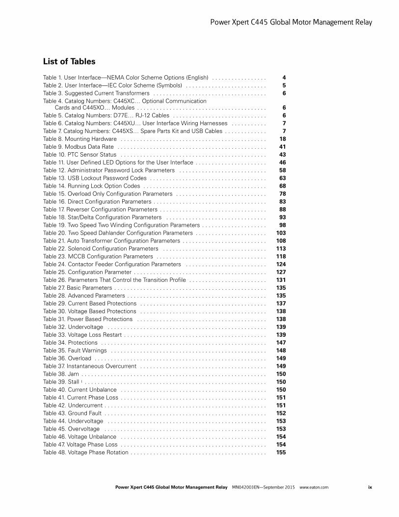
Table 1. User Interface—NEMA Color Scheme Options (English) . . . . . . . . . . . . . . . . . 4
Table 2. User Interface—IEC Color Scheme (Symbols) . . . . . . . . . . . . . . . . . . . . . . . . . 5
Table 3. Suggested Current Transformers . . . . . . . . . . . . . . . . . . . . . . . . . . . . . . . . . . . 6
Table 4. Catalog Numbers: C445XC… Optional Communication Cards and C445XO… Modules . . . . . . . . . . . . . . . . . . . . . . . . . . . . . . . . . . . . . . . . 6
Table 5. Catalog Numbers: D77E… RJ-12 Cables . . . . . . . . . . . . . . . . . . . . . . . . . . . . . 6
Table 6. Catalog Numbers: C445XU… User Interface Wiring Harnesses . . . . . . . . . . . 7
Table 7. Catalog Numbers: C445XS… Spare Parts Kit and USB Cables . . . . . . . . . . . . . 7
Table 8. Mounting Hardware . . . . . . . . . . . . . . . . . . . . . . . . . . . . . . . . . . . . . . . . . . . . . 18
Table 9. Modbus Data Rate . . . . . . . . . . . . . . . . . . . . . . . . . . . . . . . . . . . . . . . . . . . . . . 41
Table 10. PTC Sensor Status . . . . . . . . . . . . . . . . . . . . . . . . . . . . . . . . . . . . . . . . . . . . . 43
Table 11. User Defined LED Options for the User Interface . . . . . . . . . . . . . . . . . . . . . . 46
Table 12. Administrator Password Lock Parameters . . . . . . . . . . . . . . . . . . . . . . . . . . . 58
Table 13. USB Lockout Password Codes . . . . . . . . . . . . . . . . . . . . . . . . . . . . . . . . . . . . 63
Table 14. Running Lock Option Codes . . . . . . . . . . . . . . . . . . . . . . . . . . . . . . . . . . . . . . 68
Table 15. Overload Only Configuration Parameters . . . . . . . . . . . . . . . . . . . . . . . . . . . . 78
Table 16. Direct Configuration Parameters . . . . . . . . . . . . . . . . . . . . . . . . . . . . . . . . . . . 83
Table 17. Reverser Configuration Parameters . . . . . . . . . . . . . . . . . . . . . . . . . . . . . . . . . 88
Table 18. Star/Delta Configuration Parameters . . . . . . . . . . . . . . . . . . . . . . . . . . . . . . . 93
Table 19. Two Speed Two Winding Configuration Parameters . . . . . . . . . . . . . . . . . . . . 98
Table 20. Two Speed Dahlander Configuration Parameters . . . . . . . . . . . . . . . . . . . . . . 103
Table 21. Auto Transformer Configuration Parameters . . . . . . . . . . . . . . . . . . . . . . . . . . 108
Table 22. Solenoid Configuration Parameters . . . . . . . . . . . . . . . . . . . . . . . . . . . . . . . . 113
Table 23. MCCB Configuration Parameters . . . . . . . . . . . . . . . . . . . . . . . . . . . . . . . . . . 118
Table 24. Contactor Feeder Configuration Parameters . . . . . . . . . . . . . . . . . . . . . . . . . 124
Table 25. Configuration Parameter . . . . . . . . . . . . . . . . . . . . . . . . . . . . . . . . . . . . . . . . . 127
Table 26. Parameters That Control the Transition Profile . . . . . . . . . . . . . . . . . . . . . . . . 131
Table 27. Basic Parameters . . . . . . . . . . . . . . . . . . . . . . . . . . . . . . . . . . . . . . . . . . . . . . . 135
Table 28. Advanced Parameters . . . . . . . . . . . . . . . . . . . . . . . . . . . . . . . . . . . . . . . . . . . 135
Table 29. Current Based Protections . . . . . . . . . . . . . . . . . . . . . . . . . . . . . . . . . . . . . . . 137
Table 30. Voltage Based Protections . . . . . . . . . . . . . . . . . . . . . . . . . . . . . . . . . . . . . . . 138
Table 31. Power Based Protections . . . . . . . . . . . . . . . . . . . . . . . . . . . . . . . . . . . . . . . . 138
Table 32. Undervoltage . . . . . . . . . . . . . . . . . . . . . . . . . . . . . . . . . . . . . . . . . . . . . . . . . 139
Table 33. Voltage Loss Restart . . . . . . . . . . . . . . . . . . . . . . . . . . . . . . . . . . . . . . . . . . . . 139
Table 34. Protections . . . . . . . . . . . . . . . . . . . . . . . . . . . . . . . . . . . . . . . . . . . . . . . . . . . 147
Table 35. Fault Warnings . . . . . . . . . . . . . . . . . . . . . . . . . . . . . . . . . . . . . . . . . . . . . . . . 148
Table 36. Overload . . . . . . . . . . . . . . . . . . . . . . . . . . . . . . . . . . . . . . . . . . . . . . . . . . . . . 149
Table 37. Instantaneous Overcurrent . . . . . . . . . . . . . . . . . . . . . . . . . . . . . . . . . . . . . . . 149
Table 38. Jam . . . . . . . . . . . . . . . . . . . . . . . . . . . . . . . . . . . . . . . . . . . . . . . . . . . . . . . . . 150
Table 39. Stall 1 . . . . . . . . . . . . . . . . . . . . . . . . . . . . . . . . . . . . . . . . . . . . . . . . . . . . . . . . 150
Table 40. Current Unbalance . . . . . . . . . . . . . . . . . . . . . . . . . . . . . . . . . . . . . . . . . . . . . 150
Table 41. Current Phase Loss . . . . . . . . . . . . . . . . . . . . . . . . . . . . . . . . . . . . . . . . . . . . . 151
Table 42. Undercurrent . . . . . . . . . . . . . . . . . . . . . . . . . . . . . . . . . . . . . . . . . . . . . . . . . . 151
Table 43. Ground Fault . . . . . . . . . . . . . . . . . . . . . . . . . . . . . . . . . . . . . . . . . . . . . . . . . . 152
Table 44. Undervoltage . . . . . . . . . . . . . . . . . . . . . . . . . . . . . . . . . . . . . . . . . . . . . . . . . 153
Table 45. Overvoltage . . . . . . . . . . . . . . . . . . . . . . . . . . . . . . . . . . . . . . . . . . . . . . . . . . 153
Table 46. Voltage Unbalance . . . . . . . . . . . . . . . . . . . . . . . . . . . . . . . . . . . . . . . . . . . . . 154
Table 47. Voltage Phase Loss . . . . . . . . . . . . . . . . . . . . . . . . . . . . . . . . . . . . . . . . . . . . . 154
Table 48. Voltage Phase Rotation . . . . . . . . . . . . . . . . . . . . . . . . . . . . . . . . . . . . . . . . . . 155
Power Xpert C445 Global Motor Management Relay MN042003EN—September 2015 www.eaton.com ix
Power Xpert C445 Global Motor Management Relay
List of Tables, continued
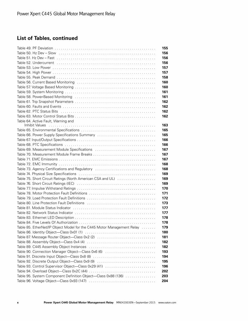
Table 49. PF Deviation . . . . . . . . . . . . . . . . . . . . . . . . . . . . . . . . . . . . . . . . . . . . . . . . . . 155
Table 50. Hz Dev – Slow . . . . . . . . . . . . . . . . . . . . . . . . . . . . . . . . . . . . . . . . . . . . . . . . 156
Table 51. Hz Dev – Fast . . . . . . . . . . . . . . . . . . . . . . . . . . . . . . . . . . . . . . . . . . . . . . . . . 156
Table 52. Undercurrent . . . . . . . . . . . . . . . . . . . . . . . . . . . . . . . . . . . . . . . . . . . . . . . . . 156
Table 53. Low Power . . . . . . . . . . . . . . . . . . . . . . . . . . . . . . . . . . . . . . . . . . . . . . . . . . . 157
Table 54. High Power . . . . . . . . . . . . . . . . . . . . . . . . . . . . . . . . . . . . . . . . . . . . . . . . . . . 157
Table 55. Peak Demand . . . . . . . . . . . . . . . . . . . . . . . . . . . . . . . . . . . . . . . . . . . . . . . . . 158
Table 56. Current Based Monitoring . . . . . . . . . . . . . . . . . . . . . . . . . . . . . . . . . . . . . . . 160
Table 57. Voltage Based Monitoring . . . . . . . . . . . . . . . . . . . . . . . . . . . . . . . . . . . . . . . . 160
Table 59. System Monitoring . . . . . . . . . . . . . . . . . . . . . . . . . . . . . . . . . . . . . . . . . . . . . 161
Table 58. Power-Based Monitoring . . . . . . . . . . . . . . . . . . . . . . . . . . . . . . . . . . . . . . . . 161
Table 61. Trip Snapshot Parameters . . . . . . . . . . . . . . . . . . . . . . . . . . . . . . . . . . . . . . . . 162
Table 60. Faults and Events . . . . . . . . . . . . . . . . . . . . . . . . . . . . . . . . . . . . . . . . . . . . . . 162
Table 62. PTC Status Bits . . . . . . . . . . . . . . . . . . . . . . . . . . . . . . . . . . . . . . . . . . . . . . . 162
Table 63. Motor Control Status Bits . . . . . . . . . . . . . . . . . . . . . . . . . . . . . . . . . . . . . . . . 162
Table 64. Active Fault, Warning andInhibit Values . . . . . . . . . . . . . . . . . . . . . . . . . . . . . . . . . . . . . . . . . . . . . . . . . . . . . 163
Table 65. Environmental Specifications . . . . . . . . . . . . . . . . . . . . . . . . . . . . . . . . . . . . . 165
Table 66. Power Supply Specifications Summary . . . . . . . . . . . . . . . . . . . . . . . . . . . . . 165
Table 67. Input/Output Specifications . . . . . . . . . . . . . . . . . . . . . . . . . . . . . . . . . . . . . . . 166
Table 68. PTC Specifications . . . . . . . . . . . . . . . . . . . . . . . . . . . . . . . . . . . . . . . . . . . . . 166
Table 69. Measurement Module Specifications . . . . . . . . . . . . . . . . . . . . . . . . . . . . . . 167
Table 70. Measurement Module Frame Breaks . . . . . . . . . . . . . . . . . . . . . . . . . . . . . . . 167
Table 71. EMC Emissions . . . . . . . . . . . . . . . . . . . . . . . . . . . . . . . . . . . . . . . . . . . . . . . . 167
Table 72. EMC Immunity . . . . . . . . . . . . . . . . . . . . . . . . . . . . . . . . . . . . . . . . . . . . . . . . 168
Table 73. Agency Certifications and Regulatory . . . . . . . . . . . . . . . . . . . . . . . . . . . . . . 168
Table 74. Physical Size Specifications . . . . . . . . . . . . . . . . . . . . . . . . . . . . . . . . . . . . . . 169
Table 75. Short Circuit Ratings (North American CSA and UL) . . . . . . . . . . . . . . . . . . . 169
Table 76. Short Circuit Ratings (IEC) . . . . . . . . . . . . . . . . . . . . . . . . . . . . . . . . . . . . . . . 169
Table 77. Impulse Withstand Ratings . . . . . . . . . . . . . . . . . . . . . . . . . . . . . . . . . . . . . . . 170
Table 78. Motor Protection Fault Definitions . . . . . . . . . . . . . . . . . . . . . . . . . . . . . . . . . 171
Table 79. Load Protection Fault Definitions . . . . . . . . . . . . . . . . . . . . . . . . . . . . . . . . . . 172
Table 80. Line Protection Fault Definitions . . . . . . . . . . . . . . . . . . . . . . . . . . . . . . . . . . 173
Table 81. Module Status Indicator . . . . . . . . . . . . . . . . . . . . . . . . . . . . . . . . . . . . . . . . . 177
Table 82. Network Status Indicator . . . . . . . . . . . . . . . . . . . . . . . . . . . . . . . . . . . . . . . . 177
Table 83. Ethernet LED Description . . . . . . . . . . . . . . . . . . . . . . . . . . . . . . . . . . . . . . . . 178
Table 84. Five Levels Of Authorization . . . . . . . . . . . . . . . . . . . . . . . . . . . . . . . . . . . . . . 178
Table 85. EtherNet/IP Object Model for the C445 Motor Management Relay . . . . . . . 179
Table 86. Identity Object—Class 0x01 (1) . . . . . . . . . . . . . . . . . . . . . . . . . . . . . . . . . . . 180
Table 87. Message Router Object—Class 0x2 (2) . . . . . . . . . . . . . . . . . . . . . . . . . . . . . 181
Table 88. Assembly Object—Class 0x4 (4) . . . . . . . . . . . . . . . . . . . . . . . . . . . . . . . . . . 182
Table 89. C445 Assembly Object Instances . . . . . . . . . . . . . . . . . . . . . . . . . . . . . . . . . 182
Table 90. Connection Manager Object—Class 0x6 (6) . . . . . . . . . . . . . . . . . . . . . . . . . 193
Table 91. Discrete Input Object—Class 0x8 (8) . . . . . . . . . . . . . . . . . . . . . . . . . . . . . . . 194
Table 92. Discrete Output Object—Class 0x9 (9) . . . . . . . . . . . . . . . . . . . . . . . . . . . . . 195
Table 93. Control Supervisor Object—Class 0x29 (41) . . . . . . . . . . . . . . . . . . . . . . . . . 196
Table 94. Overload Object—Class 0x2C (44) . . . . . . . . . . . . . . . . . . . . . . . . . . . . . . . . . 202
Table 95. System Component Definition Object—Class 0x88 (136) . . . . . . . . . . . . . . . 203
Table 96. Voltage Object—Class 0x93 (147) . . . . . . . . . . . . . . . . . . . . . . . . . . . . . . . . . 204
x Power Xpert C445 Global Motor Management Relay MN042003EN—September 2015 www.eaton.com

Power Xpert C445 Global Motor Management Relay
List of Tables, continued
Table 97. Dynamic input Assembly Interface Object—Class 0x96 (150) . . . . . . . . . . . . 206
Table 98. Dynamic Input Assembly Instance Parameters . . . . . . . . . . . . . . . . . . . . . . . 207
Table 99. Test Only Object—Class 0xC7 (199) . . . . . . . . . . . . . . . . . . . . . . . . . . . . . . . . 207
Table 100. Motor Info Object—Class 0x9B (155) . . . . . . . . . . . . . . . . . . . . . . . . . . . . . . 209
Table 101. Operation Mode Object—Class 0x9F (159) . . . . . . . . . . . . . . . . . . . . . . . . . . 210
Table 102. Modbus Object—Class 0xA0 (160) . . . . . . . . . . . . . . . . . . . . . . . . . . . . . . . . 211
Table 103. Motor Monitoring Object—Class 0xA1 (161) . . . . . . . . . . . . . . . . . . . . . . . . 212
Table 104. Motor Protection Object—Class 0xA2 (162) . . . . . . . . . . . . . . . . . . . . . . . . . 213
Table 105. Snapshot Object—Class 0xA5 (165) . . . . . . . . . . . . . . . . . . . . . . . . . . . . . . . 217
Table 107. RTC Object—Class 0xB0 (176) . . . . . . . . . . . . . . . . . . . . . . . . . . . . . . . . . . . . 218
Table 106. Parameter Access Object—Class 0xAA (170) . . . . . . . . . . . . . . . . . . . . . . . . 218
Table 108. BCM Object—Class 0xB1 (177) . . . . . . . . . . . . . . . . . . . . . . . . . . . . . . . . . . 219
Table 109. BUI Object—Class 0xB2 (178) . . . . . . . . . . . . . . . . . . . . . . . . . . . . . . . . . . . 220
Table 110. Option Card Object—Class 0xB3 (179) . . . . . . . . . . . . . . . . . . . . . . . . . . . . . 221
Table 111. Port Object—Class 0xF4 (244) . . . . . . . . . . . . . . . . . . . . . . . . . . . . . . . . . . . . 222
Table 112. TCP/IP Object—Class 0xF5 (245) . . . . . . . . . . . . . . . . . . . . . . . . . . . . . . . . . 223
Table 113. Ethernet Link Object—Class 0xF6 (246) . . . . . . . . . . . . . . . . . . . . . . . . . . . . 224
Table 114. Modbus TCP Function Codes . . . . . . . . . . . . . . . . . . . . . . . . . . . . . . . . . . . . 226
Table 115. Modbus Data Rate . . . . . . . . . . . . . . . . . . . . . . . . . . . . . . . . . . . . . . . . . . . . 228
Table 116. PROFIBUS D-Shell Connector Specifications . . . . . . . . . . . . . . . . . . . . . . . . 228
Table 117. DB-9 Connector . . . . . . . . . . . . . . . . . . . . . . . . . . . . . . . . . . . . . . . . . . . . . . . 228
Table 118. PROFIBUS Card LED Definitions . . . . . . . . . . . . . . . . . . . . . . . . . . . . . . . . . 229
Table 119. C445 Diagnostic Telegram Details . . . . . . . . . . . . . . . . . . . . . . . . . . . . . . . . . 232
Table 120. PROFIBUS Configuration File . . . . . . . . . . . . . . . . . . . . . . . . . . . . . . . . . . . . 234
Table 121. Bit Mapping Parameters for Cyclic/Acyclic Writeable Parameters . . . . . . . . . 235
Table 122. Fieldbus Motor Control Bits . . . . . . . . . . . . . . . . . . . . . . . . . . . . . . . . . . . . . 235
Table 123. Bit Mapping Parameters for Cyclic/Acyclic Readable Parameters . . . . . . . . . 235
Table 124. PROFIBUS Cyclic/Acyclic Readable Parameters . . . . . . . . . . . . . . . . . . . . . . 236
Table 125. C445 Modbus Register Map . . . . . . . . . . . . . . . . . . . . . . . . . . . . . . . . . . . . . 237
Power Xpert C445 Global Motor Management Relay MN042003EN—September 2015 www.eaton.com xi

Power Xpert C445 Global Motor Management Relay
Safety
Definitions and Symbols
WARNING
This symbol indicates high voltage. It calls your attentionto items or operations that could be dangerous to youand other persons operating this equipment. Read themessage and follow the instructions carefully.
This symbol is the “Safety Alert Symbol.” It occurs witheither of two signal words: CAUTION or WARNING, asdescribed below.
WARNING
Indicates a potentially hazardous situation which, if notavoided, can result in serious injury or death.
CAUTION
Indicates a potentially hazardous situation which, if notavoided, can result in minor to moderate injury, or seriousdamage to the product. The situation described in theCAUTION may, if not avoided, lead to serious results.Important safety measures are described in CAUTION (aswell as WARNING).
Hazardous High Voltage
WARNING
Motor control equipment and electronic controllers areconnected to hazardous line voltages. When servicingdrives and electronic controllers, there may be exposedcomponents with housings or protrusions at or aboveline potential. Extreme care should be taken to protectagainst shock.
Stand on an insulating pad and make it a habit to use onlyone hand when checking components. Always work withanother person in case an emergency occurs. Disconnectpower before checking controllers or performingmaintenance. Be sure equipment is properly grounded. Wearsafety glasses whenever working on electronic controllers orrotating machinery.
Warnings and CautionsThis manual contains clearly marked cautions and warnings which are intended for your personal safety and to avoid any unintentional damage to the product or connected appliances.
Please read the information included in cautions and warnings carefully.
WARNING
The C445 may reset at any time enabling a motor start.When faulted (FAULT LED is ON) the READY LED willflash when an auto reset is pending.
CAUTION
Record all passwords in a safe location. Once a password hasbeen set it cannot be displayed. If a password is forgottenthe only method of resetting the password(s) is a factoryreset.
CAUTION
In the Auto Reset mode, caution must be exercised to assurethat any restart occurs in a safe manner. Auto Reset modeshould not be used in environments where excessive restartattempts may cause component damage and/or createunsafe conditions.
CAUTION
The motor, the wiring diameter and the switching device(s)must be suitable for the selected Trip Class.
CAUTION
The current-dependent protective device must be selectedso that not only is the motor current monitored but theblocked motor is switched OFF within the temperature risetime.
xii Power Xpert C445 Global Motor Management Relay MN042003EN—September 2015 www.eaton.com
Chapter 1—Power Xpert C445 Overview
Chapter 1—Power Xpert C445 Overview
System Overview
The Power Xpert® C445 is an advanced, global motor management relay with full line, load and motor system monitoring and protection. It is designed to protect single or three phase AC electric induction motors ranging from 0.3 to 800 A. In the event of an overload trip, C445 disconnects power flow to the monitored motor. C445 additionally provides advanced monitoring and control algorithms for efficiency, torque, speed, energy deviation, and voltage loss restart.
C445 offers a modular pass-through design, separating monitoring, protection and control functionality into individual modules. This allows the user to select the appropriate options for each module and combine them to meet the exact needs of their application. The C445 also offers multiple pre-programmed operation modes to support fast, easy and error-free installation for the majority of applications.
How to Use this Manual
The purpose of this manual is to provide you with information necessary to install, set and customize parameters, start-up, troubleshoot and maintain the Eaton Power Xpert C445 global motor management relay. To provide for safe installation and operation of the equipment, read the safety guidelines at the beginning of this manual and follow the procedures outlined in the following chapters before connecting power to the Eaton Power Xpert C445 global motor management relay. Keep this operating manual handy and distribute to all users, technicians and maintenance personnel for reference.
Power Xpert C445 Global Motor Management Relay MN042003EN—September 2015 www.eaton.com 1

Chapter 1—Power Xpert C445 Overview
Catalog Numbering
Relay
Figure 1. C445 System Catalog Numbering
Base Control Module
Figure 2. Base Control Module Catalog Numbering
Notes1 For other communication protocol options, please see Table 4, Optional Communication Cards and Modules, on Page 6.2 If a Real-Time Clock and Memory Backup Module are required, please see Table 4, Optional Communication Cards and Modules, on Page 6.
Measurement Module
Figure 3. Measurement Module Catalog Numbering
ModuleB = Base Control Module
M = Measurement ModuleU = User interfaceX = Accessory
C445 B
FamilyC445 = Power Xpert C445 global motor management relay
OptionsOptions depend on module selected
FamilyC445 = Power Xpert C445 global
motor management relay
ModuleB = Base Control Module
C445 B A – S A L N
OutputsL = 2 Form A (NO); 1 Form C (NO/NC) latching
N = 2 Form A (NO); 1 Form C (NO/NC) non-latching
Supply VoltageA = 120–240 VacD = 24 Vdc
VersionS = Standard
InputsA = 120 VacD = 24 Vdc
Options 12
N = NoneM = On-board Modbus Serial
Inputs 45 mm2P4 = 0.3–2.4 A005 = 1–5 A032 = 4–32 A045 = 6–45 A
55 mm072 = 9–72 A
90 mm090 = 11–90 A136 = 17–136 A
FamilyC445 = Power Xpert C445 global
motor management relay
ModuleM = Measurement Module
C445 M A – 005 A
Frame SizeA = 45 mm (0.3–45 A) B = 55 mm (9–72 A)C = 90 mm (17–136 A)
Sensing CapabilityI = Current only
V = Current and voltageP = Current and PTCA = Current, voltage and PTC
2 Power Xpert C445 Global Motor Management Relay MN042003EN—September 2015 www.eaton.com

Chapter 1—Power Xpert C445 Overview
User Interface
Figure 4. User Interface Catalog Numbering
Color SchemeN = NEMAI = IEC
Note: See images below.
FamilyC445 = Power Xpert C445 global
motor management relay
ModuleU = User interface
C445 U C – N 0
TypeC = Control
Application0–9Note: See tables below for selection.
Power Xpert C445 Global Motor Management Relay MN042003EN—September 2015 www.eaton.com 3
Chapter 1—Power Xpert C445 Overview
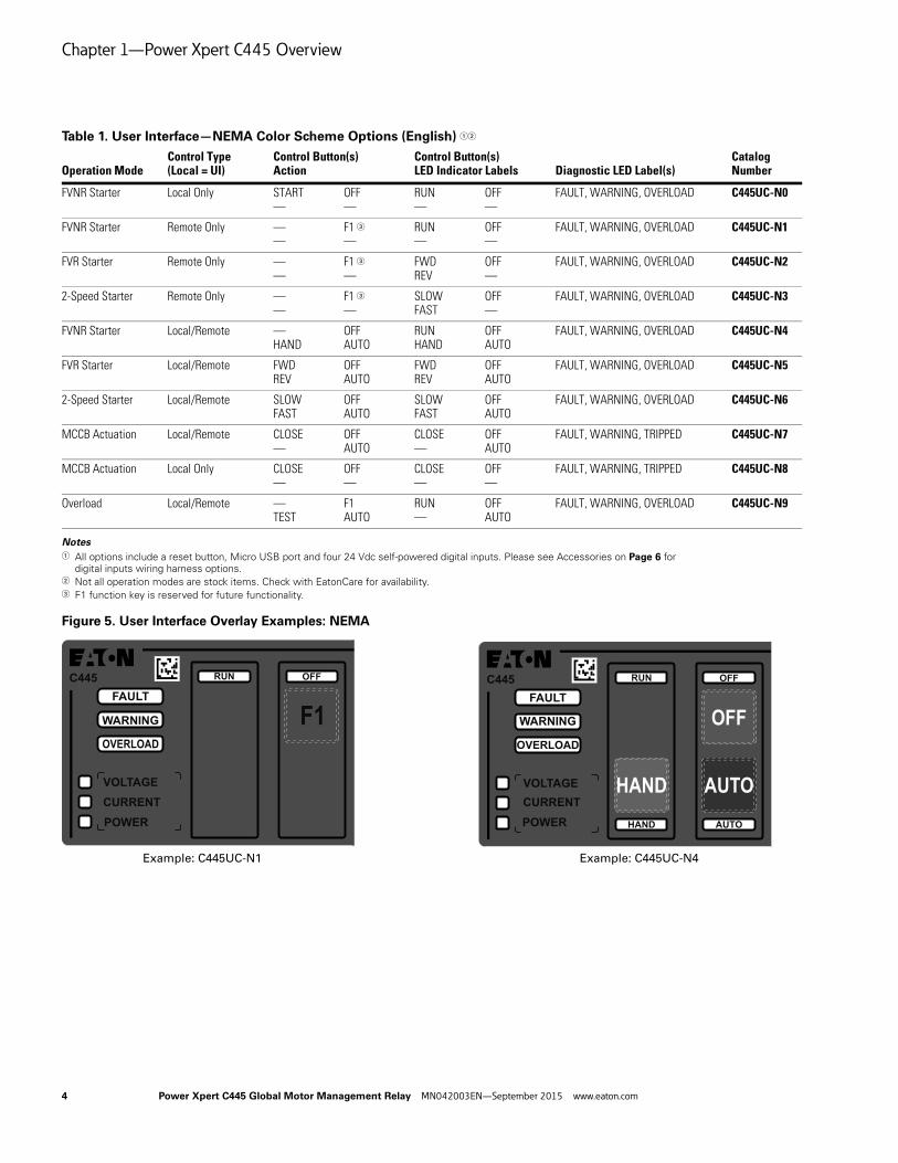
Table 1. User Interface—NEMA Color Scheme Options (English) 12
Notes1 All options include a reset button, Micro USB port and four 24 Vdc self-powered digital inputs. Please see Accessories on Page 6 for
digital inputs wiring harness options.2 Not all operation modes are stock items. Check with EatonCare for availability.3 F1 function key is reserved for future functionality.
Figure 5. User Interface Overlay Examples: NEMA
Operation ModeControl Type (Local = UI)
Control Button(s)Action
Control Button(s) LED Indicator Labels Diagnostic LED Label(s)
CatalogNumber
FVNR Starter Local Only START —
OFF—
RUN—
OFF—
FAULT, WARNING, OVERLOAD C445UC-N0
FVNR Starter Remote Only ——
F1 3—
RUN—
OFF—
FAULT, WARNING, OVERLOAD C445UC-N1
FVR Starter Remote Only ——
F1 3—
FWDREV
OFF—
FAULT, WARNING, OVERLOAD C445UC-N2
2-Speed Starter Remote Only ——
F1 3—
SLOWFAST
OFF—
FAULT, WARNING, OVERLOAD C445UC-N3
FVNR Starter Local/Remote —HAND
OFFAUTO
RUNHAND
OFFAUTO
FAULT, WARNING, OVERLOAD C445UC-N4
FVR Starter Local/Remote FWDREV
OFFAUTO
FWDREV
OFFAUTO
FAULT, WARNING, OVERLOAD C445UC-N5
2-Speed Starter Local/Remote SLOWFAST
OFFAUTO
SLOWFAST
OFFAUTO
FAULT, WARNING, OVERLOAD C445UC-N6
MCCB Actuation Local/Remote CLOSE—
OFFAUTO
CLOSE—
OFFAUTO
FAULT, WARNING, TRIPPED C445UC-N7
MCCB Actuation Local Only CLOSE—
OFF—
CLOSE—
OFF—
FAULT, WARNING, TRIPPED C445UC-N8
Overload Local/Remote —TEST
F1AUTO
RUN—
OFFAUTO
FAULT, WARNING, OVERLOAD C445UC-N9
C445
F1RUN OFF
FAULT
WARNING
OVERLOAD
VOLTAGECURRENTPOWER
C445
HAND
OFF
AUTO
RUN
HAND AUTO
OFF
FAULT
WARNING
OVERLOAD
VOLTAGECURRENTPOWER
Example: C445UC-N1 Example: C445UC-N4
4 Power Xpert C445 Global Motor Management Relay MN042003EN—September 2015 www.eaton.com

Chapter 1—Power Xpert C445 Overview
Table 2. User Interface—IEC Color Scheme (Symbols) 12
Notes1 All options include a reset button, Micro USB port and four 24 Vdc self-powered digital inputs. Please see Accessories on Page 6 for
digital inputs wiring harness options.2 Not all operation modes are stock items. Check with EatonCare for availability.
Figure 6. User Interface Overlay Examples: IEC
Operation ModeControl Type (Local = UI)
Control Button(s)Action
Control Button(s) LED Indicator Labels Diagnostic LED Label(s)
CatalogNumber
FVNR Starter Local Only ——
——
FAULT, WARNING, EARTH FAULT C445UC-I0
FVNR Starter Remote Only ——
F1 —
RUN—
OFF—
FAULT, WARNING, EARTH FAULT C445UC-I1
FVR Starter Remote Only ——
——
FAULT, WARNING, EARTH FAULT C445UC-I2
2-Speed Starter Remote Only ——
——
FAULT, WARNING, EARTH FAULT C445UC-I3
FVNR Starter Local/Remote ——
——
FAULT, WARNING, EARTH FAULT C445UC-I4
FVR Starter Local/Remote ——
——
FAULT, WARNING, EARTH FAULT C445UC-I5
2-Speed Starter Local/Remote ——
——
FAULT, WARNING, EARTH FAULT C445UC-I6
MCCB Actuation Local/Remote ——
——
FAULT, WARNING, TRIPPED C445UC-I7
MCCB Actuation Local Only ——
——
FAULT, WARNING, TRIPPED C445UC-I8
Overload Local/Remote —TEST
F1 AUTO
RUN—
OFF—
FAULT, WARNING, EARTH FAULT C445UC-I9
— —
—
—
— AUTO
AUTO
AUTO
— AUTO
— —
C445
AUTO
FAULT
WARNING
EARTH FAULT
VOLTAGECURRENTPOWER
C445
F1RUN OFF
VOLTAGECURRENTPOWER
FAULT
WARNING
EARTH FAULT
Example: C445UC-I1 Example: C445UC-I4
Power Xpert C445 Global Motor Management Relay MN042003EN—September 2015 www.eaton.com 5

Chapter 1—Power Xpert C445 Overview
Accessories
Current Transformer
C445 measurement modules are designed to be used in applications up to 136 A. For applications beyond 136 A, external CTs with a 5 A output may be used.
CT Kits do not include Measurement Modules.
Table 3. Suggested Current Transformers 1
Note1 Contact factory for availability. Catalog numbers are for one single-phase CT including a mounting
bracket. Order quantity of 3 for a complete C445 system.
Communication and Option Modules
Table 4. Catalog Numbers: C445XC… Optional Communication Cards and C445XO… Modules
Cables, Wiring Harnesses and Spare Parts
D77E connection cables are required to connect the Base Control Module to the Measurement Module and to the user interface. Use the appropriate lengths for each connection.
Table 5. Catalog Numbers: D77E… RJ-12 Cables
User interface wiring harnesses are required to utilize the digital inputs on the User Interface. Use one wiring harness
per user interface to connect to these inputs.
CT Range (A) Description Terminal Size Measurement Module Catalog Number
17–300 300:5 Single-Phase CT, 1.25 inch dia hole, UL & CSA ANSI/IEEE C57.13, 50–400 Hz, 600 Vac, 10 kV, relay class C50, accuracy 0.3% B0.1
(2) 8–32 brass terminals, comes with mounting bracket kit
C445MA-005_ XCT300-5
75–600 600:5 Single-Phase CT, 2.00 inch dia hole, UL & CSA ANSI/IEEE C57.13, 50–400 Hz, 600 Vac, 10 kV, relay class C50, accuracy 0.3% B0.1
(2) 8–32 brass terminals, comes with mounting bracket kit
C445MA-005_ XCT600-5
100–800 800:5 Single-Phase CT, 2.50 inch dia hole, UL & CSA ANSI/IEEE C57.13, 50–400 Hz, 600 Vac, 10 kV, relay class C50, accuracy 0.3% B0.1
(2) 8–32 brass terminals, comes with mounting bracket kit
C445MA-005_ XCT800-5
Description Catalog Number
EtherNet/IP and Modbus TCP card with 2-port switch C445XC-E
PROFIBUS DPV1 and DPV0 card C445XC-P
Real-Time Clock and Memory Backup Module C445XO-RTC
Description Catalog Number
Connection cable (Base Control Module to Measurement Module or user interface), 13 cm length, 600 V rating D77E-QPIP13
Connection cable (Base Control Module to Measurement Module or user interface), 13 cm length, 1000 V rating D77E-QPIP13-HV
Connection cable (Base Control Module to Measurement Module or user interface), 25 cm length, 600 V rating D77E-QPIP25
Connection cable (Base Control Module to Measurement Module or user interface), 25 cm length, 1000 V rating D77E-QPIP25-HV
Connection cable (Base Control Module to Measurement Module or user interface), 100 cm length, 600 V rating D77E-QPIP100
Connection cable (Base Control Module to Measurement Module or user interface), 100 cm length, 1000 V rating D77E-QPIP100-HV
Connection cable (Base Control Module to Measurement Module or user interface), 200 cm length, 600 V rating D77E-QPIP200
Connection cable (Base Control Module to Measurement Module or user interface), 300 cm length, 600 V rating D77E-QPIP300
Connection cable (Base Control Module to Measurement Module or user interface), 300 cm length, 1000 V rating D77E-QPIP300-HV
6 Power Xpert C445 Global Motor Management Relay MN042003EN—September 2015 www.eaton.com

Chapter 1—Power Xpert C445 Overview
Table 6. Catalog Numbers: C445XU… User Interface Wiring Harnesses
USB cables are used to connect to Power Xpert inControl software tool via USB port to the Base Control Module or the User Interface.
Table 7. Catalog Numbers: C445XS… Spare Parts Kit and USB Cables
Description Catalog Number
User interface digital inputs wiring harness, 50 cm, 16 AWG wires C445XU-050
User interface digital inputs wiring harness, 100 cm, 16 AWG wires C445XU-100
User interface digital inputs wiring harness, 200 cm, 16 AWG wires C445XU-200
User interface digital inputs wiring harness, 300 cm, 16 AWG wires C445XU-300
User interface digital inputs wiring harness, 100 cm, 1 mm2 wires C445XU-100CXH
Description Catalog Number
Spare parts kit – terminal connectors, mounting feet C445XS-TERM
Standard USB A Male to Micro USB Male cable C445XS-USBMICRO
Standard USB A Male to RJ12 cable C445XS-USBRJ12
Standard USB A Male to Loose Leads cable (for use with Modbus Serial terminals) C445XS-USBLEADS
Power Xpert C445 Global Motor Management Relay MN042003EN—September 2015 www.eaton.com 7

Chapter 1—Power Xpert C445 Overview
Modules Overview
Base Control Module Basic Overview
The Base Control Module is the controller of the C445 system, providing the various monitoring, protection and control algorithms. Equipped with native I/O connections, communication card options and USB connectivity, the Base Control Module provides users with real-time data on the health and status of their applications. Various pre-configured operation modes are available that simplify the wiring and logic requirements for the user.
Figure 7. Base Control Module Image
Base Control Module Features● Motor protection
● Current, voltage, power and system monitoring
● Pre-configured operating modes
● 120/240 Vac or 24 Vdc supply voltage options
● Four 120 Vac or 24 Vdc inputs, 2NO and 1NO/1NC relay outputs
● Integrated USB port
● Real-time clock and memory backup module option slot
● Multiple fieldbus communication options
● Status LEDs
● Provides power and communications to the Measurement Module and the user interface through the cable connection
Figure 8. Base Module Features and Connections—Front View
DIP Switches: Used for node addressing and configuration selections.
Output Status: LEDs indicate the ON/OFF status of each output.
Input Status: LEDs indicate the ON/OFF status of each input.
Inputs: Four digital inputs available. Must be purchased as 24 Vdc or 120 Vac.
Test/Reset: Used to manually trip the Base Control Module. Also used to reset the module after a trip has occurred.
USB Port: Micro AB connector. Enables configuration upload.
Status LEDs:
● Status: Indicates the fault and warning status of the Base Control Module
● CH1: Indicates status of modules attached to Channel 1 port on Base Control Module (Measurement Module or user interface)
● CH2: Indicates status of modules attached to Channel 2 port on Base Control Module (Measurement Module or user interface)
● USB: USB traffic indication
Real Time Clock and Memory Backup Module: Optional real time clock module. Plugs in behind the communication cards. Provides battery backed-up fault time stamping and non-volatile memory for configuration parameters.
Communication Cards: Optional modules to provide communications.
● PROFIBUS DVP0 and DVP1 (Shown)
● Ethernet for Modbus/TCP and EtherNet/IP
DIP Switches
Output Status
Input Status
Inputs
Communication Modules
RTC Module
Status LEDs
USB PortTest/Reset
8 Power Xpert C445 Global Motor Management Relay MN042003EN—September 2015 www.eaton.com

Chapter 1—Power Xpert C445 Overview
Figure 9. Base Module Features and Connections—Bottom View
Relay Outputs 1 & 2: Two normally open outputs.
Relay Output 3: Form C NC/NO. Factory orderable as latching or non-latching.
Two options available: 120–240 Vac or 24 Vdc
RS-485: Modbus Serial terminal (factory orderable option only)
CH1 Port: Provides communication and power from the Base Control Module to the connected module (Measurement Module or user interface)
CH2 Port: Provides connection and power from the Base Control Module to the connected module (Measurement Module or user interface)
Measurement Module Basic Overview
The Measurement Module is a pass-through device which samples current and voltage data consumed by the system. This data is continually transmitted back to the Base Control Module for analysis. Various frame sizes are available for applications up to 800 A, with factory orderable options for voltage measurement and positive temperature coefficient (PTC) protection.
Figure 10. Measurement Module Image
Measurement Module Features● 0.3–136 A pass-through current measurement ● External CTs for applications up to 800 A● Optional line voltage measurement and protection
● Optional positive temperature coefficient (PTC) protection
● DIN rail or panel mounting
● The Measurement Module is powered through its cable connection to the Base Control Module
Figure 11. Measurement Module Features and Connections
Voltage Terminals: Optional Factory installed terminals for measuring line voltage. Required for monitoring voltage, power and energy and related protection features. Cannot be installed in the field.
PTC Terminal: Optional factory installed terminal for Positive Temperature Coefficient (PTC) protection. PTC protection uses temperature measurement signals from the motors stator windings. Cannot be installed in the field.
RJ-12 Terminal: Connection port to the Base Control Module.
Pass through current measurement: for measuring motor lead current from 0.3 to 136 A.
Relay Outputs 1 & 2
RS-485
Input Power
CH1 Port
Relay Output 3
CH2 Port
Measurement Module Top
PTC Terminal RJ-12 Terminal
Voltage Terminals
Measurement Module Bottom
Pass throughcurrentmeasurement
Power Xpert C445 Global Motor Management Relay MN042003EN—September 2015 www.eaton.com 9
Chapter 1—Power Xpert C445 Overview
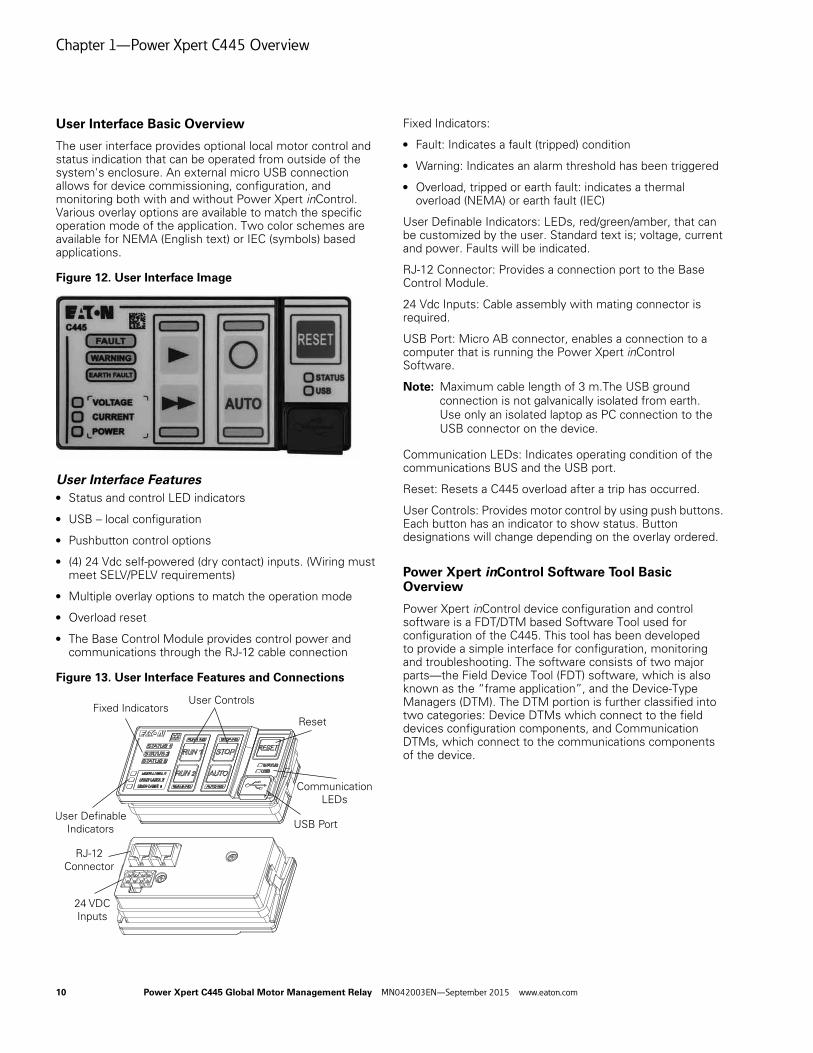
User Interface Basic Overview
The user interface provides optional local motor control and status indication that can be operated from outside of the system's enclosure. An external micro USB connection allows for device commissioning, configuration, and monitoring both with and without Power Xpert inControl. Various overlay options are available to match the specific operation mode of the application. Two color schemes are available for NEMA (English text) or IEC (symbols) based applications.
Figure 12. User Interface Image
User Interface Features● Status and control LED indicators
● USB – local configuration
● Pushbutton control options
● (4) 24 Vdc self-powered (dry contact) inputs. (Wiring must meet SELV/PELV requirements)
● Multiple overlay options to match the operation mode
● Overload reset
● The Base Control Module provides control power and communications through the RJ-12 cable connection
Figure 13. User Interface Features and Connections
Fixed Indicators:
● Fault: Indicates a fault (tripped) condition
● Warning: Indicates an alarm threshold has been triggered
● Overload, tripped or earth fault: indicates a thermal overload (NEMA) or earth fault (IEC)
User Definable Indicators: LEDs, red/green/amber, that can be customized by the user. Standard text is; voltage, current and power. Faults will be indicated.
RJ-12 Connector: Provides a connection port to the Base Control Module.
24 Vdc Inputs: Cable assembly with mating connector is required.
USB Port: Micro AB connector, enables a connection to a computer that is running the Power Xpert inControl Software.
Note: Maximum cable length of 3 m.The USB ground connection is not galvanically isolated from earth. Use only an isolated laptop as PC connection to the USB connector on the device.
Communication LEDs: Indicates operating condition of the communications BUS and the USB port.
Reset: Resets a C445 overload after a trip has occurred.
User Controls: Provides motor control by using push buttons. Each button has an indicator to show status. Button designations will change depending on the overlay ordered.
Power Xpert inControl Software Tool Basic Overview
Power Xpert inControl device configuration and control software is a FDT/DTM based Software Tool used for configuration of the C445. This tool has been developed to provide a simple interface for configuration, monitoring and troubleshooting. The software consists of two major parts—the Field Device Tool (FDT) software, which is also known as the “frame application”, and the Device-Type Managers (DTM). The DTM portion is further classified into two categories: Device DTMs which connect to the field devices configuration components, and Communication DTMs, which connect to the communications components of the device.
User Controls
RJ-12 Connector
24 VDC Inputs
Reset
Communication LEDs
Indicators USB Port
Fixed Indicators
10 Power Xpert C445 Global Motor Management Relay MN042003EN—September 2015 www.eaton.com

Chapter 1—Power Xpert C445 Overview
Pre-Defined Operating Modes Basic Overview
The C445 relay has several predefined configurations referred to as operation modes. Selecting one of these operation modes will determine the behavior of some or all of the inputs and outputs of the C445 relay.
Each predefined operating mode can be controlled by way of 2-wire or 3-wire control wiring both with and without the User Interface option. The Pre-defined Operating modes available are:
● Overload Only
● Direct Online
● Reverser
● Star/Delta
● Two Speed Two Winding
● Two Speed Dahlander
● Auto Transformer
● Solenoid Valve
● MCCB Actuation
● Contactor Feeder
● General Purpose Input/Output
See System Operation on Page 75 for detailed explanations of each operating mode.
Power Xpert C445 Global Motor Management Relay MN042003EN—September 2015 www.eaton.com 11

Chapter 2—Receipt/Unpacking
Chapter 2—Receipt/Unpacking
Do not service with voltage applied; use Lock-out Tags.
General
Upon receipt of the unit, verify that the catalog number and unit options stated on the shipping container match those stated on the order/purchase form.
Inspect the equipment upon delivery. Report any crate or carton damage to the carrier prior to accepting the delivery. Have this information noted on the freight bill. Eaton is not responsible for damage incurred in shipping.
Unpacking
Remove all packing material from the unit. Check the unit for any signs of shipping damage. If damage is found after unpacking, report it to the freight company. Retain the packaging materials for carrier to review.
Verify that the unit’s catalog number and options match those stated on the order/purchase form.
Storage
It is recommended that the unit be stored in its original shipping box/crate until it is to be installed.
The unit should be stored in a location where:
● The ambient temperature is -40ºC – 85ºC
● The relative humidity is 0% – 95%, non-condensing
● The environment is dry, clean and non-corrosive
● The unit will not be subjected to high shock or vibration conditions
12 Power Xpert C445 Global Motor Management Relay MN042003EN—September 2015 www.eaton.com

Chapter 3—Installation and Wiring
Chapter 3—Installation and Wiring
Introduction
This chapter provides a description of the mounting and electrical connection(s) to the Power Xpert C445 global motor management relay.
While installing and/or mounting the relay, cover all openings to ensure that no foreign materials can enter the device.
Perform all installation work with the specified tools and without the use of excessive force.
The C445 relay must only be mounted on a non-combustible base.
Relevant mounting and installation instructions are provided in the following instruction leaflets:
IL043001EN for C44B… Base Control Module
IL043003EN for C445M... Measurement Modules
IL043002EN for C445U… User Interface
Mounting Positions
The maximum permissible angle of inclination for all C445 devices is shown below:
Figure 14. Vertical Position Limits
Power Xpert C445 Global Motor Management Relay MN042003EN—September 2015 www.eaton.com 13

Chapter 3—Installation and Wiring
Clearance
An installation clearance of 10 mm must be maintained in front of any C445 device. A top and bottom clearance of 10 mm each is required. A minimum of 10 mm side clearance is required between any C445 devices.
Figure 15. Clearance Dimensions
Figure 16. Clearance Dimensions (Side)
≥10 mm (≥0.39")
≥10 mm (≥0.39")
14 Power Xpert C445 Global Motor Management Relay MN042003EN—September 2015 www.eaton.com

Chapter 3—Installation and Wiring
C445 Module Assembly
Note: Power down the C445 before adding or removing option cards or RTC module.
Figure 17. Component Exploded View (C445B...Base Module, C445M...Measurement Module, Accessory Cover, C445XO-TRTC Real Time Clock Module, C445C... Communications card(s))
Figure 18. Option Cover Removal
Remove the C445 Option Cover to install the Real Time Clock Module (RTC), Cat # and/or Communication Cards, Cat#.If installing only the RTC module, replace the cover on the C445 Base Module.If installing any Communications card, the cover is no longer required and can be discarded.
2 1
Power Xpert C445 Global Motor Management Relay MN042003EN—September 2015 www.eaton.com 15

Chapter 3—Installation and Wiring
Figure 19. Real-Time Clock and Memory Backup Module Installation
Remove the C445B... Option Cover as shown in Figure 18. The C445XO-RTC module installation is facilitated by a notch on the upper right corner of the module to provide proper orientation of the module.Firmly push the module into the C445B... pocket until the module is completely seated.Reinstall Option Cover.
16 Power Xpert C445 Global Motor Management Relay MN042003EN—September 2015 www.eaton.com

Chapter 3—Installation and Wiring
Figure 20. Communication Card Installation
Remove the C445B... Option Cover as shown in Figure 18. The Option Cover may be discarded as it will not be reinstalled.The C445XC-E or C445XC-P communication card installation is accomplished by firmly pushing the card downward into the C445B... communications card pocket until the card is completely seated and the locking tab snaps into place.
Figure 21. Component Mating
The C445B... Base Module can be attached to the top of the C445MA... Measurement module.Orient both modules so the two (2) RJ12 jacks on the C445B... module are on the same side as the RJ12 jack on the C445MA... module. Align the modules so there is an offset of 0.098–0.157 in (2.3–4.0 mm).Slide the C445B... Base Module downward on the C445MA... Measurement Module until the locking tab moves into place.
1
2
Power Xpert C445 Global Motor Management Relay MN042003EN—September 2015 www.eaton.com 17
Chapter 3—Installation and Wiring
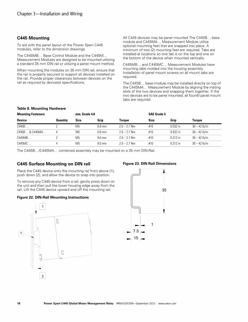
C445 Mounting
To aid with the panel layout of the Power Xpert C445 modules, refer to the dimension drawings.
The C445MB… Base Control Module and the C445M… Measurement Modules are designed to be mounted utilizing a standard 35 mm DIN rail or utilizing a panel mount method.
When mounting the modules on 35 mm DIN rail, ensure that the rail is properly secured to support all devices installed on the rail. Provide proper clearances between devices on the rail as required by device(s) specifications.
All C445 devices may be panel mounted The C445B… base module and C445MA… Measurement Module utilize optional mounting feet that are snapped into place. A minimum of two (2) mounting feet are required. Tabs are installed at locations so one tab is on the top and one on the bottom of the device when mounted vertically.
C445MB… and C445MC… Measurement Modules have mounting tabs molded into the housing assembly. Installation of panel mount screws on all mount tabs are required.
The C445B… base module may be installed directly on top of the C445MA… Measurement Module by aligning the mating slots of the two devices and snapping them together. If the two devices are to be panel mounted, all four(4) panel mount tabs are required.
Table 8. Mounting Hardware
The C445B…/C445MA… combined assembly may be mounted on a 35 mm DIN-Rail.
C445 Surface Mounting on DIN rail
Place the C445 device onto the mounting rail from above [1], push down [2], and allow the device to snap into position.
To remove any C445 device from a rail, gently press down on the unit and then pull the lower housing edge away from the rail. Lift the C445 device upward and off the mounting rail.
Figure 22. DIN-Rail Mounting Instructions
Figure 23. DIN Rail Dimensions
Mounting Fasteners mm, Grade 4.8 SAE Grade 5
Device Quantity Size Grip Torque Size Grip Torque
C445B… 2 M5 0.8 mm 2.0 – 2.7 Nm #10 0.032 in 30 – 42 lb/in
C445B… & C445MA… 4 M5 0.8 mm 2.0 – 2.7 Nm #10 0.032 in 30 – 42 lb/in
C445MB… 2 M5 8.0 mm 2.0 – 2.7 Nm #10 0.312 in 30 – 42 lb/in
C445MC… 4 M5 8.0 mm 2.0 – 2.7 Nm #10 0.312 in 30 – 42 lb/in
1
1
2
35
7.51
15
18 Power Xpert C445 Global Motor Management Relay MN042003EN—September 2015 www.eaton.com

Chapter 3—Installation and Wiring
C445… Mounting Dimensions—DIN Rail and Panel Mount
A minimum of two (2) mounting clips are required to panel mount the C445MA...
Mounting clip orientation is one clip on top and one on bottom of the unit.
Figure 24. Base Control Module—C445B… Mounting Dimensions
Power Xpert C445 Global Motor Management Relay MN042003EN—September 2015 www.eaton.com 19

Chapter 3—Installation and Wiring
Figure 25. Measurement Module—C445MA… Mounting Dimensions
A minimum of two (2) mounting feet are required to panel mount the C445MA...Foot orientation is one clip on top and one on bottom of the unit.
64[2.50]
PANEL MOUNTOPTION 1
97[3.81]
34[1.34]
PANEL MOUNTOPTION 2
62[2.43]
69[2.72]
PANEL MOUNT2X M5 (SAE #10)
35mm DIN RAIL MOUNT 80[3.15]
37[1.48]
43[1.67]
109[4.31]
45[1.77]
74[2.90]
80[3.15]
80[3.15]
45[1.77]
20 Power Xpert C445 Global Motor Management Relay MN042003EN—September 2015 www.eaton.com

Chapter 3—Installation and Wiring
Figure 26. Base Control Module C445B… Mounting Dimensions
45.0
[1.77]
80.0
[3.15]
37.0
[1.46]
43.0
[1.69]
156.3
[6.15]
167.1
[6.58]
PANEL MOUNTOPTION 3
PANEL MOUNT(4) M5 OR #10
62[2.43]
69[2.72]
74[2.91]
80[3.15]
95[3.74]
Power Xpert C445 Global Motor Management Relay MN042003EN—September 2015 www.eaton.com 21

Chapter 3—Installation and Wiring
Figure 27. Measurement Module C445MB… Mounting Dimensions
Figure 28. Measurement Module C445MC… Mounting Dimensions
94[3.69]MTG.
45[1.77]MTG.
56[2.22]
105[4.14]
35mm DIN RAIL MOUNT
PANEL MOUNT(2) M5 OR #10
45[1.78]
37[1.48]
116[4.55]
75[2.95]MTG.
100[3.94]MTG.
112[4.41]
90[3.56]
PANEL MOUNT(4) M5 OR #10
35mm DIN RAILMOUNT
46[1.80]
37[1.48]
84[3.31]
8[0.31]
22 Power Xpert C445 Global Motor Management Relay MN042003EN—September 2015 www.eaton.com

Chapter 3—Installation and Wiring
Figure 29. User Interface C445UC… Mounting Dimensions
USER INTERFACE MODULE CUTOUT
99[3.91]
52[2.05]
37[1.47]
32[1.24]
8[.31]
92[3.62]
45[1.77]
Power Xpert C445 Global Motor Management Relay MN042003EN—September 2015 www.eaton.com 23
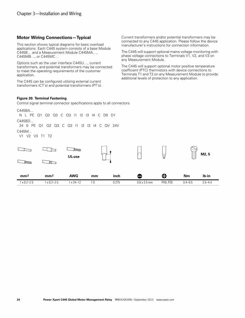
Chapter 3—Installation and Wiring
Motor Wiring Connections—Typical
This section shows typical diagrams for basic overload applications. Each C445 system consists of a base Module C445B… and a Measurement Module C445MA…, C445MB…, or C445MC…
Options such as the user interface C445U…, current transformers, and potential transformers may be connected to meet the operating requirements of the customer application.
The C445 can be configured utilizing external current transformers (CT’s) and potential transformers (PT’s).
Current transformers and/or potential transformers may be connected to any C445 application. Please follow the device manufacturer’s instructions for connection information.
The C445 will support optional mains voltage monitoring with phase voltage connections to Terminals V1, V2, and V3 on any Measurement Module.
The C445 will support optional motor positive temperature coefficient (PTC) thermistors with device connections to Terminals T1 and T2 on any Measurement Module to provide additional levels of protection to any application.
Figure 30. Terminal Fastening
Control signal terminal connector specifications apply to all connectors:
C445BA...N L PE Q1 Q2 Q3 C Q3 I1 I2 I3 I4 C D0 D1
C445BD...24 0 PE Q1 Q2 Q3 C Q3 I1 I2 I3 I4 C QV 24V
C445M...V1 V2 V3 T1 T2
1 x 0.2–2.5 1 x 0.2–2.5 1 x 24–12 7.0 0.275 0.6 x 3.5 mm PH0, PZ0 0.4–0.5 3.5–4.4
Nm lb-in
M2, 5
inchmmAWGmm2 mm2
UL-use
24 Power Xpert C445 Global Motor Management Relay MN042003EN—September 2015 www.eaton.com

Chapter 3—Installation and Wiring
Motor Connections for Standard Overload Control
Standard Overload Applications
Figure 31. Motor Connections for Standard Overload Control with C445BD…
LegendQ1 = Cable and motor protection.
Q11 = Run contactor.PTC = Positive Temperature Coefficient (PTC) sensor.
Fuse protection for V1, V2, V3 is recommended.
CH1T1 T2
V1 V2 V3
C445M...
I1 I2
C445BD...
CH1CH2
CH1
C445U...
I3 I4 C 0V 24V Q1 Q1 Q2 Q2 Q3 C Q3 24V 0V PE
C D0 D1
CH2
1 2 3 4 5 6 7 8
PTCMOTOR3~
L2
L3
PE
L1
(+) Us
(-) Us24 VDC
Optional Modbus
F1
Q11
Q1
Power Xpert C445 Global Motor Management Relay MN042003EN—September 2015 www.eaton.com 25

Chapter 3—Installation and Wiring
Figure 32. Motor Connections for Standard Overload Control with C445BA…
LegendQ1 = Cable and motor protection.
Q11 = Run contactor.PTC = Positive Temperature Coefficient (PTC) sensor.
Fuse protection for V1, V2, V3 is recommended.
CH1T1 T2
V1 V2 V3
C445M...
I1 I2
C445BA...
CH1CH2
CH1
C445U...
I3 I4 IC IC IC Q1 Q1 Q2 Q2 Q3 C Q3 PE N L
C D0 D1
CH2
1 2 3 4 5 6 7 8
PTCMOTOR3~
L2
L3
PE
L1
(+) Us
(-) Us120-240 VAC
Optional Modbus
F1
Q11
Q1
L1
26 Power Xpert C445 Global Motor Management Relay MN042003EN—September 2015 www.eaton.com

Chapter 3—Installation and Wiring
Motor Connections with External Current Transformer(s)
Figure 33. Motor Connections for Standard Overload Control Using External CTs with C445BD…
LegendQ1 = Cable and motor protection.
Q11 = Run contactor.External CT = External Current Transformer, connect in accordance with manufacturer’s instructions.
PTC = Positive Temperature Coefficient (PTC) sensor.Fuse protection for V1, V2, V3 is recommended.
PH1
EXTERNAL CT
MOTOR3~
L2
L3
PE
L1
Q11
Q1
PH2 PH3
I1 I2
C445BD...
CH1CH2
CH1
C445U...
I3 I4 C 0V 24V Q1 Q1 Q2 Q2 Q3 C Q3 24V 0V PE
C D0 D1
CH2
1 2 3 4 5 6 7 8
PTC
(+) Us
(-) Us24 VDC
Optional Modbus
CH1T1 T2
V1 V2 V3
C445M...
F1
Power Xpert C445 Global Motor Management Relay MN042003EN—September 2015 www.eaton.com 27

Chapter 3—Installation and Wiring
Figure 34. Motor Connections for Standard Overload Control Using XCT300 or XCT600 External CTs with C445BD…
Note: Ground fault and phase imbalance is not available when the XCT300 or XCT600 external current transformers are used.
PH1 PH2 PH3
EXTERNAL CT
I1 I2
C445BD...
CH1CH2
CH1
C445U...
I3 I4 C 0V 24V Q1 Q1 Q2 Q2 Q3 C Q3 24V 0V PE
C D0 D1
CH2
1 2 3 4 5 6 7 8
PTCMOTOR3~
L2
L3
PE
L1
(+) Us
(-) Us24 VDC
Optional Modbus
Q11
Q1
CH1T1 T2
V1 V2 V3
C445M...
F1
28 Power Xpert C445 Global Motor Management Relay MN042003EN—September 2015 www.eaton.com
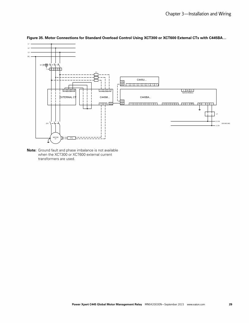
Chapter 3—Installation and Wiring
Figure 35. Motor Connections for Standard Overload Control Using XCT300 or XCT600 External CTs with C445BA…
Note: Ground fault and phase imbalance is not available when the XCT300 or XCT600 external current transformers are used.
PH1 PH2 PH3
EXTERNAL CT C445BA...
CH1CH2
CH1
C445U...
C D0 D1
CH2
1 2 3 4 5 6 7 8
PTCMOTOR3~
L2
L3
PE
L1
Optional Modbus
Q11
Q1
CH1T1 T2
V1 V2 V3
C445M...
F1
I1 I2 I3 I4 IC IC IC Q1 Q1 Q2 Q2 Q3 C Q3 PE N L
(+) Us
(-) Us120-240 VAC
L1
Power Xpert C445 Global Motor Management Relay MN042003EN—September 2015 www.eaton.com 29

Chapter 3—Installation and Wiring
Figure 36. Motor Connections for Standard Overload Control Using External CTs with C445BA…
LegendQ1 = Cable and motor protection.
Q11 = Run contactor.External CT = External Current Transformer, connect in accordance with manufacturer’s instructions.
PTC = Positive Temperature Coefficient (PTC) sensor.Fuse protection for V1, V2, V3 is recommended.
PH1
EXTERNAL CT
MOTOR3~
L2
L3
PE
L1
Q11
Q1
PH2 PH3
PTC
CH1T1 T2
V1 V2 V3
C445M...
F1
C445BA...
CH1CH2
CH1
C445U...
C D0 D1
CH2
1 2 3 4 5 6 7 8
Optional Modbus
I1 I2 I3 I4 IC IC IC Q1 Q1 Q2 Q2 Q3 C Q3 PE N L
(+) Us
(-) Us120-240 VAC
FB1FERRITE
30 Power Xpert C445 Global Motor Management Relay MN042003EN—September 2015 www.eaton.com

Chapter 3—Installation and Wiring
Figure 37. Motor Connections for Standard Overload Control Using XCT800 External CTs with C445BD…
Figure 38. Motor Connections for Standard Overload Control Using XCT800 External CTs with C445BA…
PH1
EXTERNAL CT
MOTOR3~
L2
L3
PE
L1
Q11
Q1
PH2 PH3
I1 I2
C445BD...
CH1CH2
CH1
C445U...
I3 I4 C 0V 24V Q1 Q1 Q2 Q2 Q3 C Q3 24V 0V PE
C D0 D1
CH2
1 2 3 4 5 6 7 8
PTC
(+) Us
(-) Us24 VDC
Optional Modbus
CH1T1 T2
V1 V2 V3
C445M...
F1
PH1
EXTERNAL CT
MOTOR3~
L2
L3
PE
L1
Q11
Q1
PH2 PH3
PTC
CH1T1 T2
V1 V2 V3
C445M...
F1
C445BA...
CH1CH2
CH1
C445U...
C D0 D1
CH2
1 2 3 4 5 6 7 8
Optional Modbus
I1 I2 I3 I4 IC IC IC Q1 Q1 Q2 Q2 Q3 C Q3 PE N L
(+) Us
(-) Us120-240 VAC
FB1FERRITE
Power Xpert C445 Global Motor Management Relay MN042003EN—September 2015 www.eaton.com 31

Chapter 3—Installation and Wiring
Figure 39. Motor Connections for Standard Overload Control Using Potential Transformers with C445BD…
LegendQ1 = Cable and motor protection.
Q11 = Run contactor.External CT = External Current Transformer, connect in accordance with manufacturer’s instructions.
PTC = Positive Temperature Coefficient (PTC) sensor.Fuse protection for V1, V2, V3 is recommended.
CH1T1 T2
V1 V2 V3
C445M...
I1 I2
C445BD...
CH1CH2
CH1
C445U...
I3 I4 C 0V 24V Q1 Q1 Q2 Q2 Q3 C Q3 24V 0V PE
C D0 D1
CH2
1 2 3 4 5 6 7 8
PTCMOTOR
3~
L2
L3
PE
L1
(+) Us
(-) Us24 VDC
Optional Modbus
F1
Q11
Q1
POTENTIALTRANSFORMER
32 Power Xpert C445 Global Motor Management Relay MN042003EN—September 2015 www.eaton.com

Chapter 3—Installation and Wiring
Motor Connections with Potential Transformer(s)
Figure 40. Motor Connections for Standard Overload Control Using Potential Transformers with C445BA…
LegendQ1 = Cable and motor protection.
Q11 = Run contactor.External CT = External Current Transformer, connect in accordance with manufacturer’s instructions.
PTC = Positive Temperature Coefficient (PTC) sensor.Fuse protection for V1, V2, V3 is recommended.
CH1T1 T2
V1 V2 V3
C445M... C445BA...
CH1CH2
CH1
C445U...
C D0 D1
CH2
1 2 3 4 5 6 7 8
PTCMOTOR
3~
L2
L3
PE
L1
Optional Modbus
F1
Q11
Q1
POTENTIALTRANSFORMER
I1 I2 I3 I4 IC IC IC Q1 Q1 Q2 Q2 Q3 C Q3 PE N L
(+) Us
(-) Us120-240 VAC
L1
Power Xpert C445 Global Motor Management Relay MN042003EN—September 2015 www.eaton.com 33

Chapter 3—Installation and Wiring
Power and I/O Wiring
Base Control Module
The Base Control Module is the controller of the C445 Motor Management Relay system. It provides motor protection and control algorithms and various motor data for monitoring. This module is equipped with native digital inputs for field wire control and outputs for motor control and protection. It also provides communication card options and USB connectivity for real-time data on the health and status of the motor.
Base Control Module provides the slot for optional communication cards, the connectors for digital inputs and outputs, the optional RS-485 Modbus connector, the connector for powering the system, the USB port and the DIP switches (see Figure 41). The DIP Switch settings are dependent on the communication options installed.
Figure 41. Base Control Module Features and Connections
DIP Switches
Output Status
Input Status
Inputs
Communication Modules
RTC Module
Status LEDs
USB PortTest/Reset
Relay Outputs 1 & 2
RS-485
Input Power
CH1 Port
Relay Output 3
CH2 Port
34 Power Xpert C445 Global Motor Management Relay MN042003EN—September 2015 www.eaton.com

Chapter 3—Installation and Wiring
Base Control Module LED Behavior Overview
Figure 42. Base Control Module LED Overview
Base Control Module Features● Motor protection
● Power and efficiency monitoring
● Pre-configured operating modes
● AC (120/240) and DC (24) supply power options
● (4) Inputs / (3) Outputs
● Integrated USB port
● Real time clock memory module option
● Multiple fieldbus communication options
● Status LEDs
● Provides power and communications to the Measurement Module and the user interface through RJ-12 cables.
24 Vdc and 120/240 Vac System Power
The C445 system consisting of the Base Control Module and a Measurement Module along with a number of optional modules, cards and ports are all powered from the four point connector on the Base Control Module. The Base Control Module can be powered by one of the following sources.
Input Power: Three options available, AC powered 110 Vac, 60 Hz, 220 Vac, 50 Hz, or 24 Vdc.
Figure 43. Input Power Options
Device and Motor StatusColor
-Red = Fault- Yellow = Warning-Green = No Fault/Warning
Flash Rate-Mostly ON = Actively polled >1s poll rate (any protocol)
- Mostly OFF = Not being polled from the network
CH1 & CH2 StatusColor/Flash
-Red/Slow (1s ON/1s OFF) = Connected device missing or damaged-Green/Rapid (50ms ON/50ms OFF) = Device Discovery-Green/Mostly ON (1.45s ON/50ms OFF) = Device connected, data being exchanged -Green/Mostly OFF (50ms ON/1.45s OFF) = Device connected, no data being exchanged
Modbus Status Color
-Green = Indication of traffic
USB StatusColor
-Green = Indication of traffic
Output StatusON = Output Active
OFF = Output Inactive
Input StatusON = Input Active
OFF = Input Inactive
LED TestA LED Test is performed after every reset or if commanded by the network. The test cycles through both colors on bi-color LEDs. The test lasts 2 seconds.
Power Xpert C445 Global Motor Management Relay MN042003EN—September 2015 www.eaton.com 35

Chapter 3—Installation and Wiring
Digital InputsThere are 4 digital inputs on the Base Control Module. The module can be ordered with four 24 Vdc inputs or four 120 Vac inputs. Some or all of these inputs may be used if Field Wire is selected as one of the control sources. Or, if Field Wire is not selected as one of the control sources, all of these inputs are available as general purpose inputs. The state of these inputs is available to a system controller over a supported fieldbus network. The wiring for the inputs if they are available as general purpose inputs is shown below for both 24 Vdc and 120 Vac.
The Operation mode selected along with selecting Field Wire as one of the control sources determines which inputs are available as general purpose inputs. Refer to System Configuration Operation on Page 75 for additional information on the Operation modes of the C445 and what functionality is assigned certain inputs based on the Operation mode.
For more information on the Operation modes and Input wiring if Fieldwire is selected as one of the control sources, refer to System Configuration Operation on Page 75.
Below are wiring diagrams for the inputs on the Base Control Module assuming Field Wire is not one of the control sources, i.e. all inputs are available as general purpose inputs.
AC Input OptionThe C445 Base Control Module with the AC Input option allows for up to four 120 Vac Inputs to be connected.
AC Input Field wiring is accomplished with a 7-pin, 5.00 mm pitch, removable screw terminal plug.
Figure 44. AC Field Input Terminal
Figure 45. 120 Vac Input Terminal Diagram
Pin# Circuit Description1 I1 AC Field Input 12 I2 AC Field Input 23 I3 AC Field Input 34 I4 AC Field Input 45 IC Common for AC Field Input6 IC Common for AC Field Input7 IC Common for AC Field Input
Field Inputs
1 2 3 4 5 6 7
36 Power Xpert C445 Global Motor Management Relay MN042003EN—September 2015 www.eaton.com

Chapter 3—Installation and Wiring
DC Input OptionThe C445 Base Control Module with the DC Input option allows for four isolated 24 Vdc Inputs (Option #1) or four dry contact (relay/switches) inputs (Option #2).
Figure 46. DC Field Input Terminal
Wiring Option #1—Four Isolated 24 Vdc Inputs
When using option #1, no connections are made to pins 6 or 7.
Wiring Option #2—Four Dry Contact Inputs
To use this option, pin 5 is shorted directly to pin 6. Pin 7 is connected through a switch or relay to the appropriate input.
The maximum wire length from pin 7 to the corresponding input is 10m.
DC Field Input wiring is accomplished with a 7-pin, 5.00 mm pitch, removable screw terminal plug.
Note: When using Option #2, all wiring must meet PELV requirements.
Figure 47. DC Input Wiring Option 2 (Isolated)
Figure 48. DC Input Wiring Option 2 (Non-Isolated)
Pin# Circuit Description1 I1 DC Field Input 12 I2 DC Field Input 23 I3 DC Field Input 34 I4 DC Field Input 45 C Common for DC Field Input6 0V Digital Electronics Ground7 24V Source for DC Field Inputs
Field
1 2 3 4 5 6 7
Power Xpert C445 Global Motor Management Relay MN042003EN—September 2015 www.eaton.com 37
Chapter 3—Installation and Wiring
Digital Outputs
The three digital outputs are dedicated to specific functionality based on the Operation mode selected. For example, Output 1 is used to control the contactor that energizes and de-energizes the motor for a Direct (FVNR) Motor application. In this example, Output 1 is used to control the contactor and to protect the motor. It is a normally open contact that closes when the active control source instructs it to do so, provided there are no faults or inhibits present. This same output contact opens when an active protection instructs it to do so, to protect the motor. In the case of the Direct Operation mode, only Output 1 is dedicated to this mode, leaving Outputs 2 and 3 available as general purpose relay outputs or another configurable function. This is the case for each Operation mode selected. Any of the three outputs not dedicated to an Operation mode may be used as general purpose outputs, controlled by a controller via a Fieldbus. Or, configured for another specific purpose with the Power Xpert inControl Software Tool.
Any available outputs configured as general purpose outputs are controlled by a controller via a fieldbus network such as EtherNet/IP, PROFIBUS, Modbus TCP or Modbus serial. The low 4 bits of the Field Output Control Word are used for this purpose. Any of the four low bits, 0-3 can be assigned to control any of the available outputs. In other words, bit 2 of the Field Output Control Word could be assigned to control output 2. But bit 0 could also be assigned as the control bit for that output. The Power Xpert inControl Software Tool is used to assign the bits in the Field Output Control word to the available outputs.
There are 2 bits that are needed to control output 3 if the C445 is ordered with the latching relay output option. Only output 3 can be ordered as a latching relay output. The 2 bits used for controlling output 3 when it is a latching relay are to set and reset the output. If output 3 is not ordered as a latching relay, then output 3 is controlled with one bit like outputs 1 and 2. This is the reason there are four bits in the Field Output Control word for controlling 3 outputs.
For more information on the Operation modes and associated output wiring refer to System Configuration Operation on Page 75.
All the available outputs not used for an Operation mode can be configured as general purpose outputs or can also be configured to indicate a specific Fault, Trip, Motor or Warning status. The available outputs can be configured for specific purposes using the Power Xpert inControl configuration Software Tool or via Modbus commands. Refer to Appendix D, for the Modbus Register map for C445 to perform this configuration using a Modbus master. The configuration Software Tool provides a user friendly way to configure the outputs for the various selections.
Outputs dedicated to the selected Operation mode will be shown as Reserved in the Software Tool when online with the C445. Available Outputs will be shown configured as None by default. The following functions can be selected for each of the available outputs from the following list with the Software Tool:
0: None
1: Fault Reason Type – Load Fault
2: Fault Reason Type – Supply Fault
3: Fault Reason Type – Motor fault
4: Tripped Status Bits – PTC Temperature
5: Tripped Status Bits – Phase Rotation
6: Tripped Status Bits – Stall
7: Tripped Status Bits – Overload
8: Tripped Status Bits – Exceeds Starts Limits
9: Tripped Status Bits – Low Power
10: Tripped Status Bits – High Power
11: Tripped Status Bits – Under Current
12: Tripped Status Bits – Frequency Deviation Slow
13: Tripped Status Bits – Frequency Deviation Fast
14: Tripped Status Bits – Voltage Unbalance
15: Tripped Status Bits – Voltage Phase Loss
16: Tripped Status Bits – PF Deviation
17: Tripped Status Bits – Jam
18: Tripped Status Bits – Instantaneous Over Current
19: Tripped Status Bits – Current Unbalance
20: Tripped Status Bits – Current Phase Loss
21: Tripped Status Bits – Residual GF
22: Motor Control Status – Motor at Speed
23: Motor Control Status – Ready
24: Motor Control Status – Inhibited
25: Motor Control Status – Warning
26: Motor Control Status – Fault
27: Motor Control Status – Remote Enabled
28: Motor Control Status – Running 2
29: Motor Control Status – Running 1
38 Power Xpert C445 Global Motor Management Relay MN042003EN—September 2015 www.eaton.com

Chapter 3—Installation and Wiring
30: Warning Status Bits – PTC
31: Warning Status Bits – Phase Rotation
32: Warning Status Bits – Stall
33: Warning Status Bits – Overload
34: Warning Status Bits – Exceeds Starts Limit
35: Warning Status Bits – Low Power
36: Warning Status Bits – High Power
37: Warning Status Bits – Under Current
38: Warning Status Bits – Frequency Deviation Slow
39: Warning Status Bits – Frequency Deviation Fast
40: Warning Status Bits – Voltage Unbalance
41: Warning Status Bits – Voltage Phase Loss
42: Warning Status Bits – PF Deviation
43: Warning Status Bits – Jam
44: Warning Status Bits – Instantaneous Over Current
45: Warning Status Bits – Current Unbalance
46: Warning Status Bits – Current Phase Loss
47: Warning Status Bits – Residual GF
48: Warning Status Bits – External GF
49: Warning Status Bits – Overvoltage
50: Warning Status Bits – Undervoltage
51: Tripped Status Bits – Undervoltage
52: Tripped Status Bits – Overvoltage
53: Tripped Status Bits – External GF
54: Field Output Control word – bit 0
55: Field Output Control word – bit 1
56: Field Output Control word – bit 2
57: Field Output Control word – bit 3
Outputs 1 and 2 are normally open form A relay outputs. Output 3 is a form C relay output with one normally open and one normally closed contact. When the output is energized, both contacts change state. When ordering the C445 Motor Management Relay, one of the options is to obtain a Base Control Module where Output 3 is either a standard form C relay output or a latching form C relay output.
Output 3 operation as a standard form C relay output means the output will de-energize and return the contacts to their normal state when the Base Control Module is powered off.
Output 3 operation as a latching relay output offers capability beyond what’s available from a non-latching, or a standard relay output. The energized state of the latching relay can be maintained after power has been removed from the Base Control Module. Energized means that the normally open contact will be closed and the normally closed contact will be
open. There are two additional configuration parameter for the latching relay and that involves the Power-down behavior. The following are the four choices for this behavior. These parameter can be configured using the Power Xpert inControl Software or via a Modbus message from a Modbus master. These parameters are called:
Base Control Module Relay 3 Behavior (Modbus register 719):
● Behave like a non-latching relay (default) (Modbus value = 0)
● Behave like a latching relay (Modbus value = 1)
If “Behave like a latching relay” is selected for the parameter above, then the following options are available in the Output 3 Latching Relay Behavior at Power Down parameter (Modbus register 729):
● Turn Off (default) (Modbus value = 0)
● Turn On (Modbus value = 1
● Hold Last State (Modbus value = 2)
● Toggle (Modbus value = 3)
The four bits in the Base Control Module Field Output Control word (Modbus register 601) can be assigned in any order to control the various outputs as follows:
● Output 1 Function Select: Select Field Output Control Word bit 0, 1, 2 or 3
● Output 2 Function Select: Select Field Output Control Word bit 0, 1, 2 or 3
● Output 3 Function Select: Select Field Output Control Word bit 0, 1, 2 or 3
● Output 3 Reset Function Select: Select Field Output Control Word bit 0, 1, 2 or 3 (for Latching Relay Operation only)
Refer to Appendix E for a complete C445 Modbus register map.
The outputs are relay contacts and wired as follows.
Power Xpert C445 Global Motor Management Relay MN042003EN—September 2015 www.eaton.com 39

Chapter 3—Installation and Wiring
Figure 49. 4-Point Form A (NO) Output Connector
Figure 50. 3-Point Form C (NO/NC) Output Connector
Optional RS-485 Port
If the C445 includes an RS-485 port on the Base Control Module and there is not an optional Ethernet or PROFIBUS Communication Card installed, the Modbus address and Baud Rate for this port is assigned with the DIP Switches on the Base Control Module.
If an optional PROFIBUS Card is installed, the DIP Switches on the Base Control Module double as the node address for the RS-485 Modbus port and the PROFIBUS slave module.
Figure 51. Modbus Serial Connection
If an optional Ethernet Card is installed, the DIP Switches on the Base Control Module are dedicated to the Ethernet Card’s IP address. In this case, the RS-485 port must be configured via the Power Xpert inControl Software or via Modbus commands form a Modbus master. The Modbus Register map is in Appendix D.
Note that even if there is no optional Ethernet or PROFIBUS communication card installed, the DIP Switches can be set to allow the Modbus address to be set with the configuration software.
Figure 52. RS-485 Port
Notes
● Shield shall be Earthed externally
● Shield should NOT be connected to any of these three terminals
● Wiring must meet PELV requirements
Q1 Output 1 Normally Open (NO)
Q1 Output 1 Normally Open (NO)
Q2 Output 2 Normally Open (NO)
Q2 Output 2 Normally Open (NO)
Q3 Output 3 Normally Open (NO)
C Output 3 Common
Q3 (Not) Output 3 Normally Closed (NC)
Setting Default RangeAddress 1 1 to 247Baud Rate 19200 9600, 19200, 115200Stop Bits 1 1 or 2Parity Even Even or OddMode RTU RTU or ASCII
Modbus Serial Port (RS-485)
40 Power Xpert C445 Global Motor Management Relay MN042003EN—September 2015 www.eaton.com

Chapter 3—Installation and Wiring
Base Control Module DIP Switches
DIP Switch settings when no optional communication card is installed in the Base Control Module, but the optional RS-485 Modbus port is included.
Figure 53. Base Control Module DIP Switches with Built-In Modbus
Figure 54. Base Control Module DIP Switches with PROFIBUS Card
Table 9. Modbus Data Rate
Figure 55. Base Control Module DIP Switches with Ethernet Card
Note: See Appendix C Optional Communication Cards for detailed information on each Communication Option.
B1 B0 Rate
0 0 Software Configurable
0 1 9600
1 0 115200
1 1 19200
Power Xpert C445 Global Motor Management Relay MN042003EN—September 2015 www.eaton.com 41

Chapter 3—Installation and Wiring
USB Port
The USB port on the Base Control Module is a standard Micro USB port. It supports the Modbus protocol and is typically used to interface the Power Xpert inControl Software Tool to the C445 Motor Management Relay for configuration and monitoring. Since this port supports the Modbus slave protocol, it will respond to Modbus commands from any Modbus master connected to this port. All parameters shown in the C445 Modbus Register Table in Appendix E can be accessed by the Software Tool or any Modbus master.
When a Micro B cable is connected, this port acts as a serial Modbus port with the following interface parameters:
19200 Baud, 8 bits/byte, Even Parity and 1 Stop Bit
The LED labeled “USB” above the USB port flashes green when the port is connected and data is being transferred.
Test/Reset Button
There is a small indented push button on the front of the Base Control Module that supports reset and Test Trip functions as follows:
Factory Reset – This is a power up service. With the C445 powered down, press the button and hold it while applying power. Continue to hold down the button for 5 seconds after applying power.
Test Trip – This is a runtime service. With the C445 already powered, press and hold the button for at least 5 seconds and a Test Trip Fault will occur.
Fault Reset – This is a runtime service. With the C445 already powered, press and hold the button for at least 0.5 seconds to perform a fault reset.
RJ12 Ports
The two RJ12 ports on the bottom of the Base Control Module are used to connect the Measurement Module and the optional User Interface module, to create a complete C445 Motor Management Relay system. RJ12 cables of varying lengths are available for this purpose. Refer to Table 5 on Page 6 for part numbers and cable lengths.
When a Measurement Module and an optional User Interface module are initially connected to the Base Control Module, they are automatically accepted. Either RJ12 port can be used for either module. After the C445 system is initially connected, a fault will be generated by the Base Control Module if the Measurement Module is moved to the other RJ12 port on the Base Control Module while the system is powered. This applies to the User Interface as well. A fault reset must be sent to clear this fault. If the modules are connected to different RJ12 ports while the system is powered down, no faults will be generated upon power up.
If one or both of the Measurement Module and User Interface are removed while the system is powered up or down and not plugged back into the Base Control Module, a communication loss fault will be generated. If the removed module is meant to be removed from the system permanently, a “repair” service should be sent from the Power Xpert inControl Software Tool. Following this, the device will soft reset itself and the fault will be cleared, resulting in a new system configuration without the removed module. This really only applies to removing a User Interface module since a Measurement Module is required.
Connecting a Measurement Module or User Interface module with a different part number to the Base Control Module while the system is powered will also result in a fault. A fault reset will clear the fault. If the desire is to use the new module, a “repair” service should be sent with the Software Tool. If the new module was connected by mistake, connect the correct module with the old part number and send a fault reset. A soft reset always follows a “repair” service.
Connecting a Measurement Module or User Interface module with a different part number to the Base Control Module while the system is powered down will result in a fault when the system is re-powered. A “repair” service should be sent if the desire is to use the module with the new part number. If the new module was connected by mistake, connect the module with the old part number and issue a fault reset.
A fault reset can be issued from the following sources:
1. By holding the small button on the front of the Base Control Module down for at least 0.5 seconds while the device is powered.
2. From the Power Xpert inControl Software Tool.
3. From any Modbus master to the USB port or the RS-485 port.
4. From a Modbus TCP master to the optional Ethernet card.
5. From an EtherNet/IP master to the optional Ethernet card.
Measurement Module
1. PTC Input
To utilize this optional feature, a Measurement Module must first be purchased with this feature included from the factory. This is not a field upgradable option.
Wire a compatible thermal detector, up to a 6 MARK A type PTC thermal detector across the T1 an T2 terminals of the 2-point connector on the Measurement Module. There are no settings of any kind to make in the C445.
To make this PTC input a Trip or Warning, enable it as such using the Power Xpert inControl Software Tool under the Protections category.
42 Power Xpert C445 Global Motor Management Relay MN042003EN—September 2015 www.eaton.com

Chapter 3—Installation and Wiring
To monitor the status of this input, monitor the “PTC Status” register for the following:
Table 10. PTC Sensor Status
PTC Connection: PTC wiring is connected to terminals T1 & T2 in any polarity. This connector is designed to accept 0.2 mm2 (24 AWG) to 2.5 mm2 (12 AWG) wire. The use of twisted pair wiring is strongly recommended. Shielded cable should be used when the cable lengths exceed 100ft (30m) or as needed. It's recommended that the cable shield be earth referenced near the motor frame. Cable resistance as measured at the T1 & T2 terminals must not exceed 10 ohms to retain short circuit monitoring along the entire length of the cable run
2. LEDs on the Measurement Module
Figure 56. Measurement Module LED Overview
Value Description
0 PTC ok – no fault
1 PTC overtemperature fault
2 PTC shorted fault
3 PTC open fault
Device and Motor StatusColor
-Red = Fault- Yellow = Warning-Green = No
Fault/Warning
COM Status (Communications with Base Control Module)Color/Flash
-Red/Slow (1s ON/1s OFF) = Connected device missing or failed-Green/Rapid (50ms ON/50ms OFF) = Device Discovery-Green/Mostly ON (1.45s ON/50ms OFF) = Device connected, data being exchanged -Green/Mostly OFF (50ms ON/1.45s OFF) = Device connected, no data being exchanged
Power Xpert C445 Global Motor Management Relay MN042003EN—September 2015 www.eaton.com 43
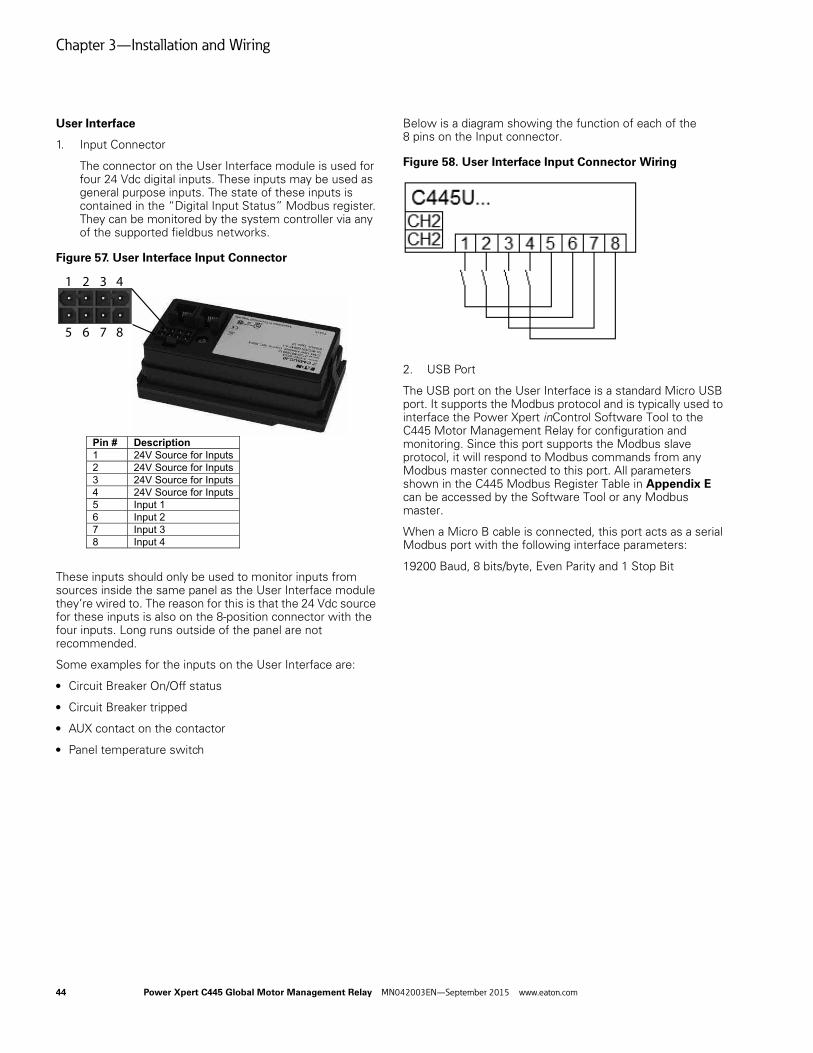
Chapter 3—Installation and Wiring
User Interface
1. Input Connector
The connector on the User Interface module is used for four 24 Vdc digital inputs. These inputs may be used as general purpose inputs. The state of these inputs is contained in the “Digital Input Status” Modbus register. They can be monitored by the system controller via any of the supported fieldbus networks.
Figure 57. User Interface Input Connector
These inputs should only be used to monitor inputs from sources inside the same panel as the User Interface module they’re wired to. The reason for this is that the 24 Vdc source for these inputs is also on the 8-position connector with the four inputs. Long runs outside of the panel are not recommended.
Some examples for the inputs on the User Interface are:
● Circuit Breaker On/Off status
● Circuit Breaker tripped
● AUX contact on the contactor
● Panel temperature switch
Below is a diagram showing the function of each of the 8 pins on the Input connector.
Figure 58. User Interface Input Connector Wiring
2. USB Port
The USB port on the User Interface is a standard Micro USB port. It supports the Modbus protocol and is typically used to interface the Power Xpert inControl Software Tool to the C445 Motor Management Relay for configuration and monitoring. Since this port supports the Modbus slave protocol, it will respond to Modbus commands from any Modbus master connected to this port. All parameters shown in the C445 Modbus Register Table in Appendix E can be accessed by the Software Tool or any Modbus master.
When a Micro B cable is connected, this port acts as a serial Modbus port with the following interface parameters:
19200 Baud, 8 bits/byte, Even Parity and 1 Stop Bit
Pin # Description1 24V Source for Inputs2 24V Source for Inputs3 24V Source for Inputs4 24V Source for Inputs5 Input 16 Input 27 Input 38 Input 4
1 2 3 4
5 6 7 8
44 Power Xpert C445 Global Motor Management Relay MN042003EN—September 2015 www.eaton.com
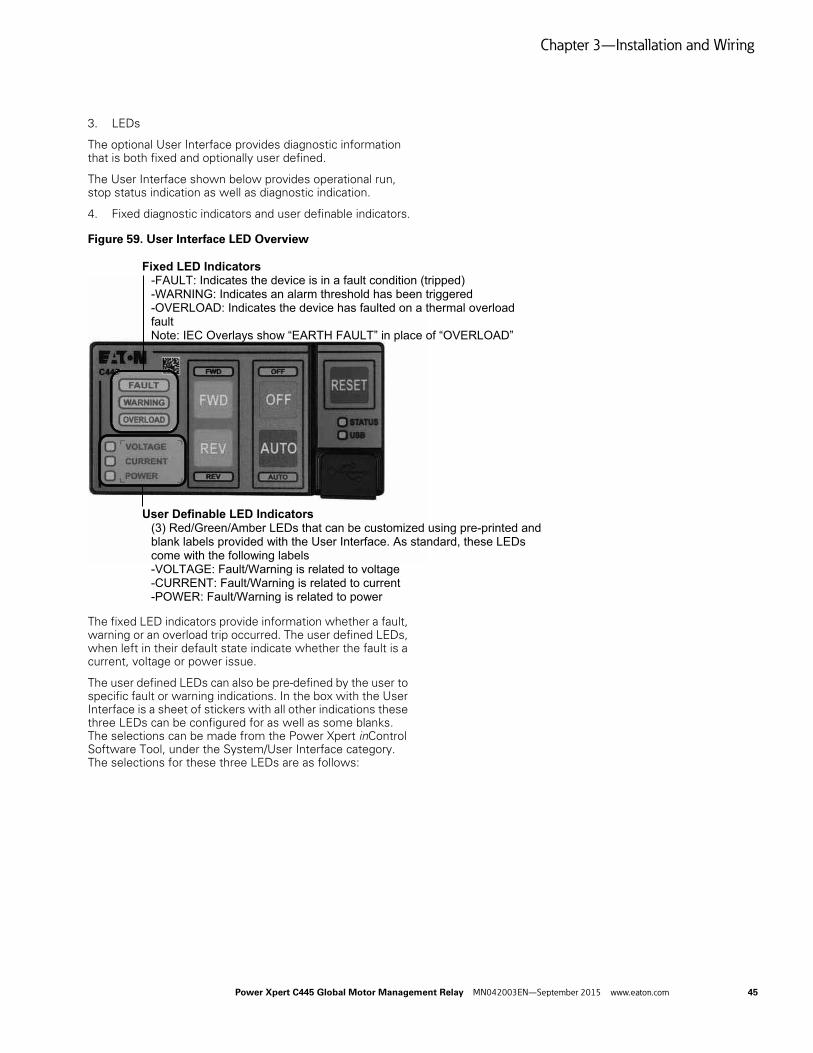
Chapter 3—Installation and Wiring
3. LEDs
The optional User Interface provides diagnostic information that is both fixed and optionally user defined.
The User Interface shown below provides operational run, stop status indication as well as diagnostic indication.
4. Fixed diagnostic indicators and user definable indicators.
Figure 59. User Interface LED Overview
The fixed LED indicators provide information whether a fault, warning or an overload trip occurred. The user defined LEDs, when left in their default state indicate whether the fault is a current, voltage or power issue.
The user defined LEDs can also be pre-defined by the user to specific fault or warning indications. In the box with the User Interface is a sheet of stickers with all other indications these three LEDs can be configured for as well as some blanks. The selections can be made from the Power Xpert inControl Software Tool, under the System/User Interface category. The selections for these three LEDs are as follows:
Fixed LED Indicators-FAULT: Indicates the device is in a fault condition (tripped)-WARNING: Indicates an alarm threshold has been triggered-OVERLOAD: Indicates the device has faulted on a thermal overload faultNote: IEC Overlays show “EARTH FAULT” in place of “OVERLOAD”
User Definable LED Indicators(3) Red/Green/Amber LEDs that can be customized using pre-printed and blank labels provided with the User Interface. As standard, these LEDs come with the following labels-VOLTAGE: Fault/Warning is related to voltage-CURRENT: Fault/Warning is related to current-POWER: Fault/Warning is related to power
Power Xpert C445 Global Motor Management Relay MN042003EN—September 2015 www.eaton.com 45

Chapter 3—Installation and Wiring
Table 11. User Defined LED Options for the User Interface
Description
NoneFault Reason Type – Load Fault (Power based)Fault Reason Type – Supply FaultFault Reason Type – Motor FaultTripped Status Bits – PTCTripped Status Bits – phase rotationTripped Status Bits – stallTripped Status Bits – overloadTripped Status Bits – exceeds starts limitTripped Status Bits – low powerTripped Status Bits – high powerTripped Status Bits – under currentTripped Status Bits – freq deviation slowTripped Status Bits – freq deviation fastTripped Status Bits – voltage unbalanceTripped Status Bits – voltage phase lossTripped Status Bits – PF deviationTripped Status Bits – jamTripped Status Bits – Instantaneous Over CurrentTripped Status Bits – Current UnbalanceTripped Status Bits – Current Phase LossTripped Status Bits – Residual GFMotor Status – Up To SpeedMotor Status – 0 = Device not ready to take any commands; 1 = Device ready to take commandsMotor Status – InhibitedMotor Status – WarningMotor Status – FaultMotor Status – Remote EnabledMotor Status – Running 2Motor Status – Running 1
Description
Warning Status Bits – PTCWarning Status Bits – phase rotationWarning Status Bits – stallWarning Status Bits – overloadWarning Status Bits – exceeds starts limitWarning Status Bits – low powerWarning Status Bits – high powerWarning Status Bits – under currentWarning Status Bits – freq deviation slowWarning Status Bits – freq deviation fastWarning Status Bits – voltage unbalanceWarning Status Bits – voltage phase lossWarning Status Bits – PF deviationWarning Status Bits – jamWarning Status Bits – instantaneous over currentWarning Status Bits – current unbalanceWarning Status Bits – current phase lossWarning Status Bits – residual GFWarning Status Bits – External GFWarning Status Bits – overvoltageWarning Status Bits – undervoltageTripped Status Bits – undervoltageTripped Status Bits – overvoltageTripped Status Bits – External GFBCM Field Output control word – bit 0 0 = disable 1= enableBCM Field Output control word – bit 1 0 = disable 1= enableBCM Field Output control word – bit 2 0 = disable 1= enableBCM Field Output control word – bit 3 0 = disable 1= enable
46 Power Xpert C445 Global Motor Management Relay MN042003EN—September 2015 www.eaton.com

Chapter 4—System Configuration and Commissioning
Chapter 4—System Configuration and Commissioning
Commissioning
There are many ways to configure a C445 Motor Management Relay. There are configuration tools that are best to use for initial commissioning and some that are faster when configuring a replacement C445 and others that are network dependent. Each will be described below.
1. The Power Xpert inControl Software configuration and monitoring tool. This Software Tool may be downloaded free of change from the Eaton website. It is a powerful Software Tool with many features including:
(1) Start-up wizard for configuring the most critical motor nameplate parameters.
(2) Categorized parameters for ease of finding the parameters needed to enable and configure particular features in the C445
(3) Ability to save configuration files for easy access later or to open and download to a replacement C445
(4) Motor Control page to monitor run status, some motor parameters such as average current and voltage as well as fault and warning codes and descriptions.
(5) Parameter compare feature between two different configuration files.
(6) Online and offline configuration for a C445 along with the ability to upload from an online device to an offline file and from an offline file to a device.
Power Xpert C445 Global Motor Management Relay MN042003EN—September 2015 www.eaton.com 47

Chapter 4—System Configuration and Commissioning
There are many more features offered by this Software Tool that are described in more detail in the Power Xpert inControl User Manual, publication MN040013EN.
To access a C445 online with this Software Tool, two protocols are supported: Modbus TCP Ethernet and Modbus Serial. In order to use Ethernet, the optional Ethernet card must be installed in the C445 Base Control Module. Using Modbus serial can be accomplished via the optional RS-485 serial port on the Base Control Module or via a Micro USB port on either the Base Control Module or the optional User Interface module.
The Micro USB ports use a standard USB/Micro USB cable. This cable may be ordered from Eaton as catalog number: C445XS-USBMICRO.
To access the C445 via the RS-485 serial port, a USB to RS-485 flying leads cable is also available from Eaton as catalog number: C445XS-USBLEADS.
48 Power Xpert C445 Global Motor Management Relay MN042003EN—September 2015 www.eaton.com

Chapter 4—System Configuration and Commissioning
2. Web Pages can be easily accessed using any web browser and an Ethernet cable connected between the computer running the Power Xpert inControl Software and the optional Ethernet card connected to the C445 Base Control Module.
An IP address or IP addressing method must be selected using the DIP Switches on the Base Control Module. Refer to Installation and Wiring on Page 13 for information on setting the DIP Switches when an Ethernet Card is installed in the C445 Base Control Module. The computer must then be configured with an IP address in the same range as the C445 Ethernet card.
Connect an Ethernet cable between the computer and the C445 Ethernet Card. Enter the IP address of the C445 Ethernet Card on the command line in the web browser and press the Enter key. In a few seconds, the Web Pages for the C445 will open as follows:
All parameters can be accessed or parameters in specific categories. The Web Pages can be used to configure parameters, monitor and control.
Power Xpert C445 Global Motor Management Relay MN042003EN—September 2015 www.eaton.com 49
Chapter 4—System Configuration and Commissioning
3. Any Modbus serial master can be connected to the optional RS-485 port or to either Micro USB port to modify any parameter that is a read/write parameter. A complete C445 Modbus Register Map is in Appendix D of this manual.
4. Any Modbus TCP Ethernet master can be used to commission a C445 provided an optional Ethernet card is installed in the C445 Base Control Module. Any read/write parameters may be modified using the Modbus Register Map in Appendix D of this manual.
5. The Ethernet card for the C445 also supports EtherNet/IP. An EtherNet/IP master can configure C445 parameters via explicit messages. Refer to Appendix C the EtherNet/IP section for additional information.
6. If a PROFIBUS option card is installed in the C445 Base Control Module, read/write parameters can be modified via the Configuration file sent from the master each time a connection is established to the C445 or from PROFIBUS DP V1 acyclic messages sent from the master. The C445 PROFIBUS Card supports both DP V0 and DP V1 PROFIBUS features. Refer to Appendix C the PROFIBUS section for additional information.
7. Optional Real-Time Clock and memory backup module (RTC module) continually reads the C445 configuration and downloads it to a replacement unit. This module is discussed in more detail later in this section.
50 Power Xpert C445 Global Motor Management Relay MN042003EN—September 2015 www.eaton.com
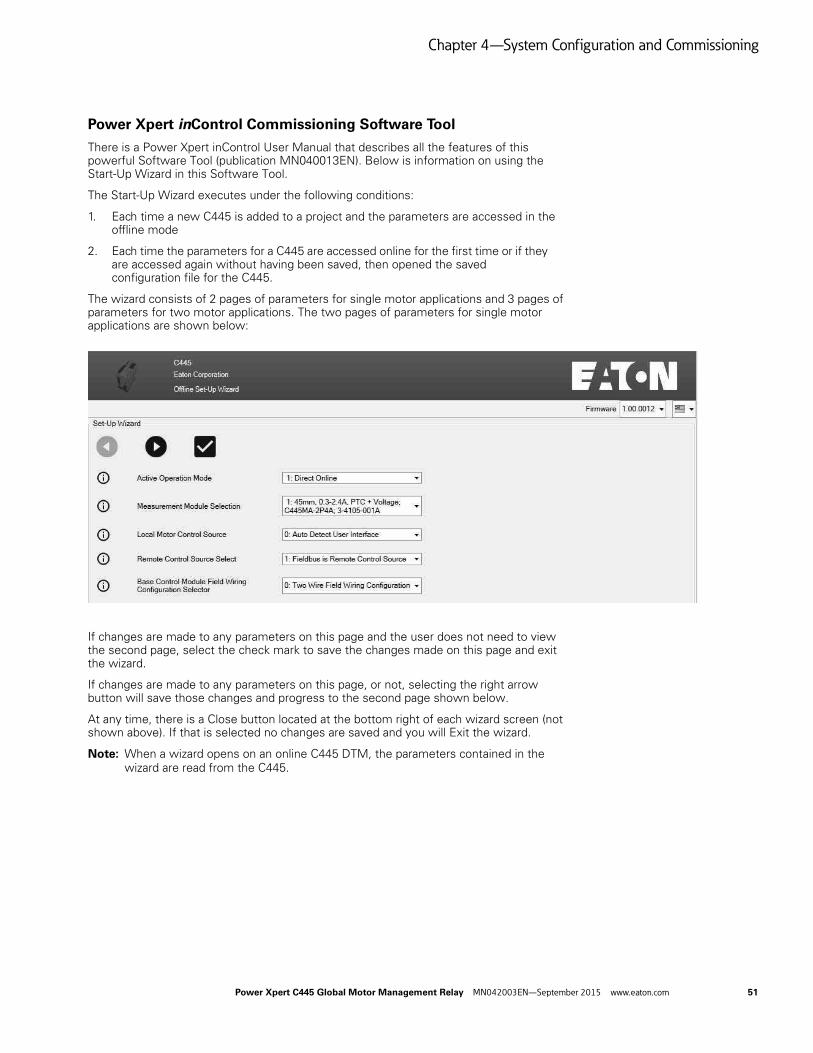
Chapter 4—System Configuration and Commissioning
Power Xpert inControl Commissioning Software Tool
There is a Power Xpert inControl User Manual that describes all the features of this powerful Software Tool (publication MN040013EN). Below is information on using the Start-Up Wizard in this Software Tool.
The Start-Up Wizard executes under the following conditions:
1. Each time a new C445 is added to a project and the parameters are accessed in the offline mode
2. Each time the parameters for a C445 are accessed online for the first time or if they are accessed again without having been saved, then opened the saved configuration file for the C445.
The wizard consists of 2 pages of parameters for single motor applications and 3 pages of parameters for two motor applications. The two pages of parameters for single motor applications are shown below:
If changes are made to any parameters on this page and the user does not need to view the second page, select the check mark to save the changes made on this page and exit the wizard.
If changes are made to any parameters on this page, or not, selecting the right arrow button will save those changes and progress to the second page shown below.
At any time, there is a Close button located at the bottom right of each wizard screen (not shown above). If that is selected no changes are saved and you will Exit the wizard.
Note: When a wizard opens on an online C445 DTM, the parameters contained in the wizard are read from the C445.
Power Xpert C445 Global Motor Management Relay MN042003EN—September 2015 www.eaton.com 51
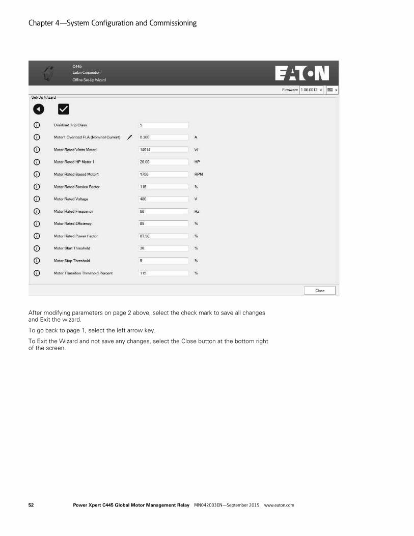
Chapter 4—System Configuration and Commissioning
After modifying parameters on page 2 above, select the check mark to save all changes and Exit the wizard.
To go back to page 1, select the left arrow key.
To Exit the Wizard and not save any changes, select the Close button at the bottom right of the screen.
52 Power Xpert C445 Global Motor Management Relay MN042003EN—September 2015 www.eaton.com
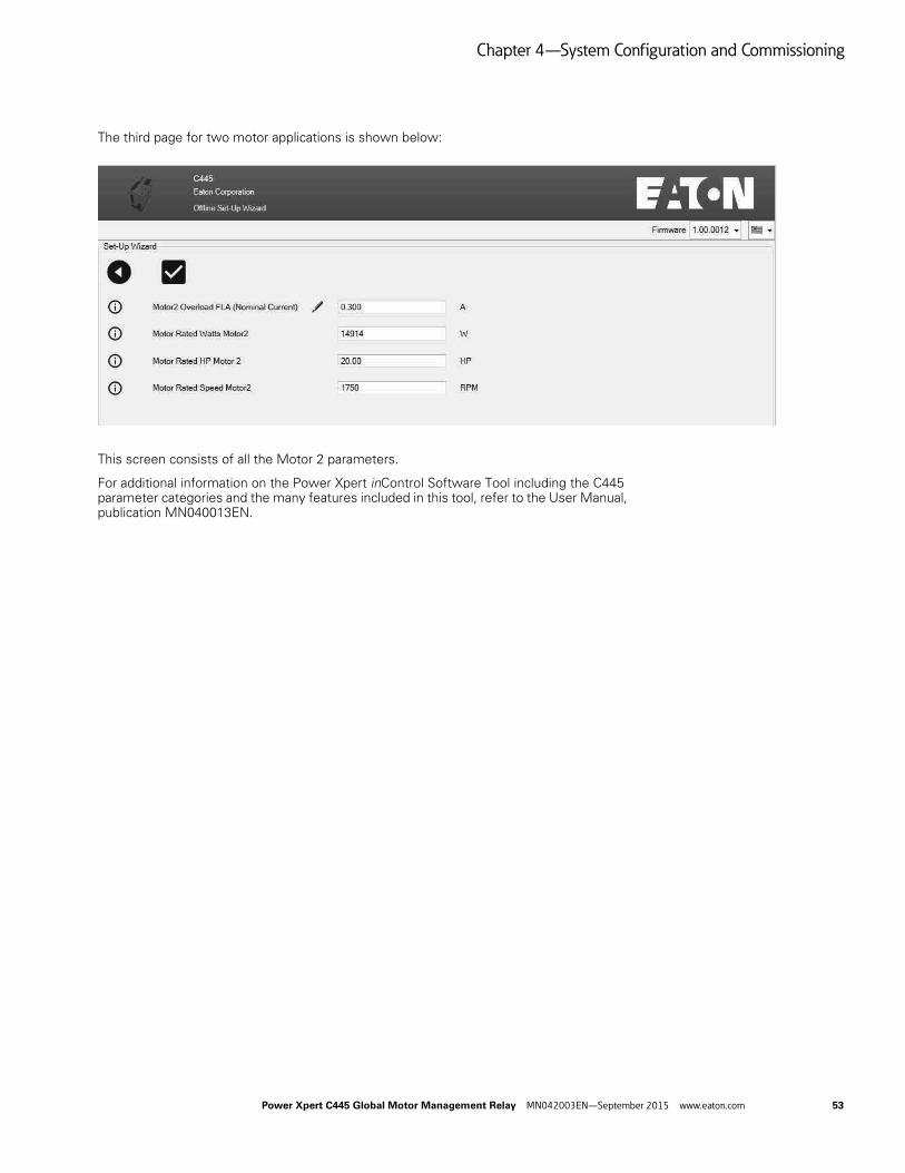
Chapter 4—System Configuration and Commissioning
The third page for two motor applications is shown below:
This screen consists of all the Motor 2 parameters.
For additional information on the Power Xpert inControl Software Tool including the C445 parameter categories and the many features included in this tool, refer to the User Manual, publication MN040013EN.
Power Xpert C445 Global Motor Management Relay MN042003EN—September 2015 www.eaton.com 53

Chapter 4—System Configuration and Commissioning
Real-Time Clock and Memory Backup Module (RTC Module)
The Real-Time Clock and Memory Backup module is an optional module that plugs into the Base Control Module. It is located under the communication card module.
This board provides non-volatile (NV) application configuration backup memory and clock time management.
Setting the Real Time Clock (RTC)
There are two ways to set the Real Time Clock parameters:
1. Using a Modbus or Modbus TCP master and writing to the RTC parameters. Refer to the Modbus register map in Appendix D.
The RTC parameters begin with Modbus register 4000. Each individual time/clock parameter can be written to set the RTC, or a single parameter (register 4010) can be written with a value containing the “Real Time clock in Seconds from the UNIX Epoch”. This is a 32 bit value.
2. Using the Power Xpert inControl Software Tool and selecting a single button to set all RTC parameters from the RTC parameters on the computer running the software.
This is the most straight forward way to set the RTC. Connect with the C445 via one of the supported protocols and ports and perform the following steps:
(1) Once online with the C445, select the Real Time Clock icon as shown below.
The Real Time Clock window will open as below.
3. Select the proper time zone.
54 Power Xpert C445 Global Motor Management Relay MN042003EN—September 2015 www.eaton.com

Chapter 4—System Configuration and Commissioning
4. Select the box to the left of “Change Date and Time” below the clock to display all the RTC parameters as shown below.
5. Select the “Sync To System Time” button and the RTC values will sync with the RTC on the computer and continue running from that point, keeping the correct time and date. The RTC module chip contains a battery to retain the RTC parameters even when power is turned off to the C445. The memory on-board the RTC module is non-volatile memory and does not use the battery to retain its contents. This will be discussed further below.
Note: Time management in the real time clock module starts using the default values (01/01/2000 00:00:00). If a real time clock board is not present then the date and time will reset to this value every time the C445 powers up. If a RTC module is installed, the time and date will increment continually.
Power Xpert C445 Global Motor Management Relay MN042003EN—September 2015 www.eaton.com 55

Chapter 4—System Configuration and Commissioning
RTC Module—Fault Snapshot
The C445 module saves and time stamps critical application data for the most recent fault, per the figure below.
This information may be accessed from the Power Xpert inControl Software Tool.
If the Base Control Module includes a real time clock board then time stamping will be in UNIX format (day of week–month–day of month–time HH:MM:SS–time zone–year).
If a real time clock board is not present then time stamping will use the number of seconds that have elapsed since the Base Control Module started up.
56 Power Xpert C445 Global Motor Management Relay MN042003EN—September 2015 www.eaton.com

Chapter 4—System Configuration and Commissioning
RTC Module—Non-Volatile Memory Operation
One of the main purposes of the RTC module is to simplify the replacement of a C445/Base Control Module if desired. The RTC module stores a copy of the configuration parameters that can be transferred to another unit with minimal downtime.
The memory module functionality in the RTC chip operates as follows:
1. When plugged into a C445/Base Control Module for the first time, the C445 will write its configuration to the non-volatile memory on the RTC module continuously.
2. When plugged into a different C445/Base Control Module, the RTC module will download the configuration to that new C445/Base Control Module. Once download is completed, the new C445/Base Control Module will begin continuously writing its configuration to the memory on the RTC module.
3. Unplugging an RTC module and plugging back into the same C445/Base Control Module will simply result in resuming normal operation. No configuration download from the memory module to the C445 will take place.
4. The RTC module uses a non-volatile memory to store the configuration parameters of the host C445/Base Control Module device.
Parameter Lock Features
The C445 supports various protection feature options for writing to its parameters, including:
1. Administrator password Lock
2. USB lockout password
3. Running Lock option
Note: The Administrator password and Running Lock option also applies to the Web Pages if an Ethernet Card is installed. The Web Pages also allow for a separate password to be set to prevent access to the parameters from the Web Pages.
Administrator Password Lock
The Admin password protection prevents anyone who has not logged into the system with the proper password from modifying any configuration parameters. All parameters may be read, but not written.
Out-of-box, there is no active Administrator password protection.
The Administrator password is a 32-bit value that can be set as a Hex, ASCII or decimal value that fits in 32-bits. Whatever format is used to set the password will need to be used when entering the password as well, to be sure it is correct. For example, if the password is set by writing an ASCII value of 1234 and later someone tries to unlock it with a decimal or hexadecimal value of 1234, it will not work.
The Modbus register addresses that store the 32-bit Administrator password are 5000/5001. The Modbus register addresses that must be written to when logging in to a system with an Administrator password set are 5002/5003.
Reading the value at register 5010 will indicate if an Administrator password is set in the device or not. If a value of 1 is read, this indicates that an Administrator password is active. A value of 0 indicates that an Administrator password is not currently active.
Power Xpert C445 Global Motor Management Relay MN042003EN—September 2015 www.eaton.com 57

Chapter 4—System Configuration and Commissioning
When 5000 and 5001 each contain hexadecimal zeros (0x0000), this means no password is set. This is also what must be written to these registers to clear a password. The only way to write to these registers if there is a password set is to first log in. Then once logged in, hexadecimal 0s can be written to these register to clear the password. A “Reset to Factory Defaults” also clears/resets the password. Since this can be accomplished using the button on the Base Control Module, a C445 with an unknown password can be recovered in this manner, but will need to be reconfigured. All parameters will have been set to factory defaults, not just the Admin password.
The Admin password can also be set using the Power Xpert inControl Software Tool, under the Security category.
Table 12. Administrator Password Lock Parameters
Parameters
Base Control Module Assigned Name
Active Operation Mode
Max Star Winding Time
Field Output Communication Fault Action
Field Output Communication Fault State
Field Output Communication Idle Action
Field Output Communication Idle State
Control Interlocking Time
Control Switching Time
Output 1 Function Select
Output 2 Function Select
Output 3 Function Select
Output 3 Function Select reset
Measurement Module Wire Config
Base Control Module Modbus Port Address
Base Control Module Modbus port Baud Rate
Base Control Module RS-485 Modbus Timeout
Base Control Module Modbus port Parity and Stop Bits
Base Control Module Modbus port TX mode
Modbus Scan List
Base Control Module USB Modbus Timeout
Motor Control Communication Loss Behavior
Motor Rated Frequency
CT Ratio - Primary
CT Ratio - Secondary
Maximum Start Current Floating Point
Maximum Start Current Scaled
Motor Rated Efficiency
Motor Rated Stator Resistance
Motor Rated HP Motor1 Scaled
Motor Rated HP Motor2 Scaled
Motor Rated PF (Scaled)
Motor Rated Service Factor
58 Power Xpert C445 Global Motor Management Relay MN042003EN—September 2015 www.eaton.com
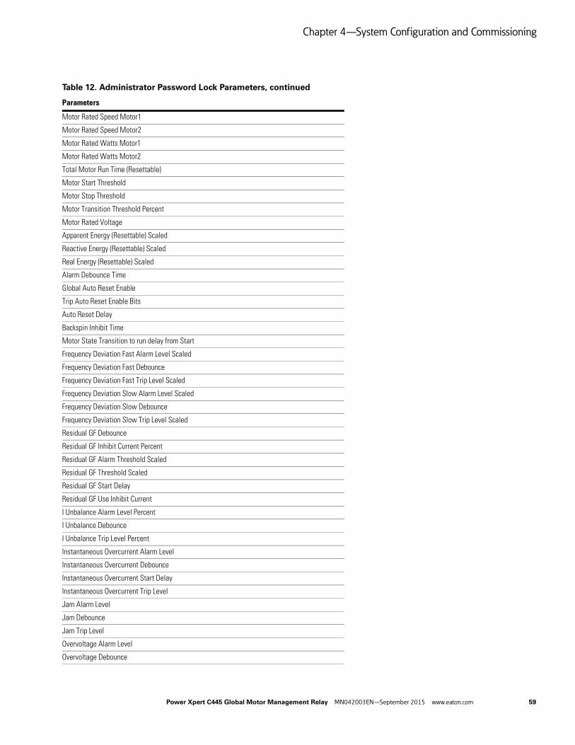
Chapter 4—System Configuration and Commissioning
Motor Rated Speed Motor1
Motor Rated Speed Motor2
Motor Rated Watts Motor1
Motor Rated Watts Motor2
Total Motor Run Time (Resettable)
Motor Start Threshold
Motor Stop Threshold
Motor Transition Threshold Percent
Motor Rated Voltage
Apparent Energy (Resettable) Scaled
Reactive Energy (Resettable) Scaled
Real Energy (Resettable) Scaled
Alarm Debounce Time
Global Auto Reset Enable
Trip Auto Reset Enable Bits
Auto Reset Delay
Backspin Inhibit Time
Motor State Transition to run delay from Start
Frequency Deviation Fast Alarm Level Scaled
Frequency Deviation Fast Debounce
Frequency Deviation Fast Trip Level Scaled
Frequency Deviation Slow Alarm Level Scaled
Frequency Deviation Slow Debounce
Frequency Deviation Slow Trip Level Scaled
Residual GF Debounce
Residual GF Inhibit Current Percent
Residual GF Alarm Threshold Scaled
Residual GF Threshold Scaled
Residual GF Start Delay
Residual GF Use Inhibit Current
I Unbalance Alarm Level Percent
I Unbalance Debounce
I Unbalance Trip Level Percent
Instantaneous Overcurrent Alarm Level
Instantaneous Overcurrent Debounce
Instantaneous Overcurrent Start Delay
Instantaneous Overcurrent Trip Level
Jam Alarm Level
Jam Debounce
Jam Trip Level
Overvoltage Alarm Level
Overvoltage Debounce
Table 12. Administrator Password Lock Parameters, continued
Parameters
Power Xpert C445 Global Motor Management Relay MN042003EN—September 2015 www.eaton.com 59
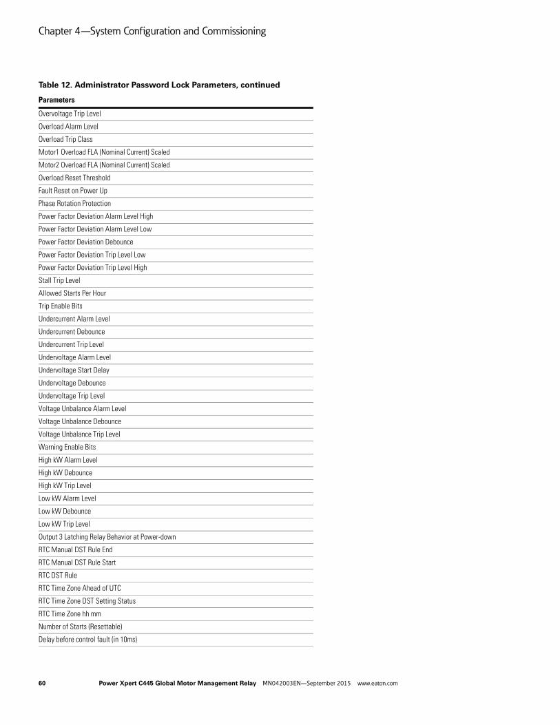
Chapter 4—System Configuration and Commissioning
Overvoltage Trip Level
Overload Alarm Level
Overload Trip Class
Motor1 Overload FLA (Nominal Current) Scaled
Motor2 Overload FLA (Nominal Current) Scaled
Overload Reset Threshold
Fault Reset on Power Up
Phase Rotation Protection
Power Factor Deviation Alarm Level High
Power Factor Deviation Alarm Level Low
Power Factor Deviation Debounce
Power Factor Deviation Trip Level Low
Power Factor Deviation Trip Level High
Stall Trip Level
Allowed Starts Per Hour
Trip Enable Bits
Undercurrent Alarm Level
Undercurrent Debounce
Undercurrent Trip Level
Undervoltage Alarm Level
Undervoltage Start Delay
Undervoltage Debounce
Undervoltage Trip Level
Voltage Unbalance Alarm Level
Voltage Unbalance Debounce
Voltage Unbalance Trip Level
Warning Enable Bits
High kW Alarm Level
High kW Debounce
High kW Trip Level
Low kW Alarm Level
Low kW Debounce
Low kW Trip Level
Output 3 Latching Relay Behavior at Power-down
RTC Manual DST Rule End
RTC Manual DST Rule Start
RTC DST Rule
RTC Time Zone Ahead of UTC
RTC Time Zone DST Setting Status
RTC Time Zone hh mm
Number of Starts (Resettable)
Delay before control fault (in 10ms)
Table 12. Administrator Password Lock Parameters, continued
Parameters
60 Power Xpert C445 Global Motor Management Relay MN042003EN—September 2015 www.eaton.com

Chapter 4—System Configuration and Commissioning
Stored Ethernet IP Address
Stored Ethernet Subnet Mask
Stored Ethernet Default Gateway
Ethernet Port 1 Speed Select
Ethernet Port 1 Full Duplex Enable
Ethernet Port 1 Autonegotiate Enable
Ethernet Port 1 Enabled
Ethernet Port 2 Speed Select
Ethernet Port 2 Full Duplex Enable
Ethernet Port 2 Autonegotiate Enabled
Ethernet Port 2 Enabled
Address Conflict Detection Enable
Modbus TCP Com Timeout
REST Web services Communication Timeout
If Protection Start Inhibit Enable
Undervoltage Start Inhibit Threshold
MCCB actuation pulse width
Voltage Unbalance Start Inhibit Threshold
Overvoltage Start Inhibit Threshold
Base Control Module Field Wiring Configuration Selector
Remote Control Source Select
Feedback Signal Source Select
Under Voltage Restart Fault Level
Under Voltage Restart Restoration Level
Demand (Resettable)
Peak Demand Time Stamp
Demand Window Duration
Local motor control source
User Interface Button LED 0 Purpose
User Interface Button LED 1 Purpose
User Interface Button LED 2 Purpose
User Interface Button LED 3 Purpose
User Interface Status LED 0 Purpose
User Interface Status LED 1 Purpose
User Interface Status LED 2 Purpose
User Interface User LED 0 Purpose
User Interface User LED 1 Purpose
User Interface User LED 2 Purpose
User Interface Button 0 CFG
User Interface Button 1 CFG
User Interface Button 2 CFG
User Interface Button 3 CFG
Table 12. Administrator Password Lock Parameters, continued
Parameters
Power Xpert C445 Global Motor Management Relay MN042003EN—September 2015 www.eaton.com 61

Chapter 4—System Configuration and Commissioning
User Interface Button 4 CFG
User Interface LED 0 color CFG
User Interface LED 1 color CFG
User Interface LED 2 color CFG
User Interface LED 3 color CFG
User Interface LED 4 color CFG
User Interface LED 5 color CFG
User Interface LED 6 color CFG
Peak Demand Warning Threshold
Enable MCCB Actuation
Voltage Loss Auto Time
Voltage Loss Short Time
Voltage Loss Long Time
Voltage Loss Short Delay
Voltage Loss Long Delay
Local/Remote power up mode
Motor Control Network Idle Behavior
Solenoid open delay time
Solenoid close delay time
Non-energized state
Input Debounce Time
Set Admin Password
Set USB Port Password
Motor Run Parameter Lock Override
Base Control Module Relay 3 Behavior
Profi-Modbus Mode
Marketing demo unlock
Table 12. Administrator Password Lock Parameters, continued
Parameters
62 Power Xpert C445 Global Motor Management Relay MN042003EN—September 2015 www.eaton.com

Chapter 4—System Configuration and Commissioning
USB Lockout Password
The USB lockout password protection prevents anyone who has not logged into the system using a USB port from modifying any configuration parameters. Parameters may be read, but not written.
Out-of-box, there is no active USB Lockout password protection.
The USB lockout password is a 32-bit value that can be set as a Hex, ASCII or decimal value that fits in 32-bits. Whatever format is used to set the password will need to be used when entering the password as well, to be sure it is correct. For example, if the password is set by writing an ASCII value of 1234 and later someone tries to unlock it with a decimal or hexadecimal value of 1234, it will not work.
The Modbus register addresses that store the 32-bit USB password are 5004/5005. The Modbus register addresses that must be written to when logging in to a system with a USB password set are 5006/5007.
Reading the value at Modbus register 5011 will indicate if a USB password is set in the device or not. If a value of 1 is read, this indicates that a USB password is active. A value of 0 indicates that a USB password is not currently active.
When 5004 and 5005 each contain hexadecimal zeros (0x0000), this means no password is set. This is also what must be written to these registers to clear a password. The only way to write to these registers if there is a password set is to first log in. Then once logged in, hexadecimal 0s can be written to these register to clear the password. A “Reset to Factory Defaults” also clears/resets the password. Since this can be accomplished using the button on the Base Control Module, a C445 with an unknown password can be recovered in this manner, but will need to be reconfigured. All parameters will have been set to factory defaults, not just the Admin password.
Table 13. USB Lockout Password Codes
Parameters
Base Control Module Assigned Name
Active Operation Mode
Max Star Winding Time
Fieldbus Motor Control
Field Output Communication Fault Action
Field Output Communication Fault State
Field Output Communication Idle Action
Field Output Communication Idle State
Control Interlocking Time
Control Switching Time
Output 1 Function Select
Output 2 Function Select
Output 3 Function Select
Output 3 Function Select reset
Measurement Module Wire Config
Base Control Module Modbus Port Address
Base Control Module Modbus port Baud Rate
Base Control Module RS-485 Modbus Timeout
Base Control Module Modbus port Parity and Stop Bits
Base Control Module Modbus port TX mode
Modbus Scan List
Power Xpert C445 Global Motor Management Relay MN042003EN—September 2015 www.eaton.com 63

Chapter 4—System Configuration and Commissioning
Base Control Module USB Modbus Timeout
Motor Control Communication Loss Behavior
Motor Rated Frequency
CT Ratio - Primary
CT Ratio - Secondary
Maximum Start Current Floating Point
Maximum Start Current Scaled
Motor Rated Efficiency
Motor Rated Stator Resistance
Motor Rated HP Motor1 Scaled
Motor Rated HP Motor2 Scaled
Motor Rated PF (Scaled)
Motor Rated Service Factor
Motor Rated Speed Motor1
Motor Rated Speed Motor2
Motor Rated Watts Motor1
Motor Rated Watts Motor2
Total Motor Run Time (Resettable)
Motor Start Threshold
Motor Stop Threshold
Motor Transition Threshold Percent
Motor Rated Voltage
Apparent Energy (Resettable) Scaled
Reactive Energy (Resettable) Scaled
Real Energy (Resettable) Scaled
Alarm Debounce Time
Global Auto Reset Enable
Trip Auto Reset Enable Bits
Auto Reset Delay
Backspin Inhibit Time
Motor State Transition to run delay from Start
Frequency Deviation Fast Alarm Level Scaled
Frequency Deviation Fast Debounce
Frequency Deviation Fast Trip Level Scaled
Frequency Deviation Slow Alarm Level Scaled
Frequency Deviation Slow Debounce
Frequency Deviation Slow Trip Level Scaled
Residual GF Debounce
Residual GF Inhibit Current Percent
Residual GF Alarm Threshold Scaled
Residual GF Threshold Scaled
Residual GF Start Delay
Table 13. USB Lockout Password Codes, continued
Parameters
64 Power Xpert C445 Global Motor Management Relay MN042003EN—September 2015 www.eaton.com

Chapter 4—System Configuration and Commissioning
Residual GF Use Inhibit Current
I Unbalance Alarm Level Percent
I Unbalance Debounce
I Unbalance Trip Level Percent
Instantaneous Overcurrent Alarm Level
Instantaneous Overcurrent Debounce
Instantaneous Overcurrent Start Delay
Instantaneous Overcurrent Trip Level
Jam Alarm Level
Jam Debounce
Jam Trip Level
Overvoltage Alarm Level
Overvoltage Debounce
Overvoltage Trip Level
Overload Alarm Level
Overload Trip Class
Motor1 Overload FLA (Nominal Current) Scaled
Motor2 Overload FLA (Nominal Current) Scaled
Overload Reset Threshold
Fault Reset on Power Up
Phase Rotation Protection
Power Factor Deviation Alarm Level High
Power Factor Deviation Alarm Level Low
Power Factor Deviation Debounce
Power Factor Deviation Trip Level Low
Power Factor Deviation Trip Level High
Stall Trip Level
Allowed Starts Per Hour
Trip Enable Bits
Undercurrent Alarm Level
Undercurrent Debounce
Undercurrent Trip Level
Undervoltage Alarm Level
Undervoltage Start Delay
Undervoltage Debounce
Undervoltage Trip Level
Voltage Unbalance Alarm Level
Voltage Unbalance Debounce
Voltage Unbalance Trip Level
Warning Enable Bits
High kW Alarm Level
High kW Debounce
Table 13. USB Lockout Password Codes, continued
Parameters
Power Xpert C445 Global Motor Management Relay MN042003EN—September 2015 www.eaton.com 65

Chapter 4—System Configuration and Commissioning
High kW Trip Level
Low kW Alarm Level
Low kW Debounce
Low kW Trip Level
Output 3 Latching Relay Behavior at Power-down
RTC Manual DST Rule End
RTC Manual DST Rule Start
RTC DST Rule
RTC Time Zone Ahead of UTC
RTC Time Zone DST Setting Status
RTC Time Zone hh mm
Number of Starts (Resettable)
Delay before control fault (in 10ms)
Stored Ethernet IP Address
Stored Ethernet Subnet Mask
Stored Ethernet Default Gateway
Ethernet Port 1 Speed Select
Ethernet Port 1 Full Duplex Enable
Ethernet Port 1 Autonegotiate Enable
Ethernet Port 1 Enabled
Ethernet Port 2 Speed Select
Ethernet Port 2 Full Duplex Enable
Ethernet Port 2 Autonegotiate Enabled
Ethernet Port 2 Enabled
Address Conflict Detection Enable
Modbus TCP Com Timeout
REST Web services Communication Timeout
If Protection Start Inhibit Enable
Undervoltage Start Inhibit Threshold
MCCB actuation pulse width
Voltage Unbalance Start Inhibit Threshold
Overvoltage Start Inhibit Threshold
Base Control Module Field Wiring Configuration Selector
Remote Control Source Select
Feedback Signal Source Select
Under Voltage Restart Fault Level
Under Voltage Restart Restoration Level
Demand (Resettable)
Peak Demand Time Stamp
Demand Window Duration
Local motor control source
User Interface Button LED 0 Purpose
Table 13. USB Lockout Password Codes, continued
Parameters
66 Power Xpert C445 Global Motor Management Relay MN042003EN—September 2015 www.eaton.com

Chapter 4—System Configuration and Commissioning
User Interface Button LED 1 Purpose
User Interface Button LED 2 Purpose
User Interface Button LED 3 Purpose
User Interface Status LED 0 Purpose
User Interface Status LED 1 Purpose
User Interface Status LED 2 Purpose
User Interface User LED 0 Purpose
User Interface User LED 1 Purpose
User Interface User LED 2 Purpose
User Interface Button 0 CFG
User Interface Button 1 CFG
User Interface Button 2 CFG
User Interface Button 3 CFG
User Interface Button 4 CFG
User Interface LED 0 color CFG
User Interface LED 1 color CFG
User Interface LED 2 color CFG
User Interface LED 3 color CFG
User Interface LED 4 color CFG
User Interface LED 5 color CFG
User Interface LED 6 color CFG
Peak Demand Warning Threshold
Enable MCCB Actuation
Voltage Loss Auto Time
Voltage Loss Short Time
Voltage Loss Long Time
Voltage Loss Short Delay
Voltage Loss Long Delay
Local/Remote power up mode
Motor Control Network Idle Behavior
Solenoid open delay time
Solenoid close delay time
Non-energized state
Input Debounce Time
Set Admin Password
Set USB Port Password
Motor Run Parameter Lock Override
Base Control Module Relay 3 Behavior
Profi-Modbus Mode
Marketing demo unlock
Table 13. USB Lockout Password Codes, continued
Parameters
Power Xpert C445 Global Motor Management Relay MN042003EN—September 2015 www.eaton.com 67
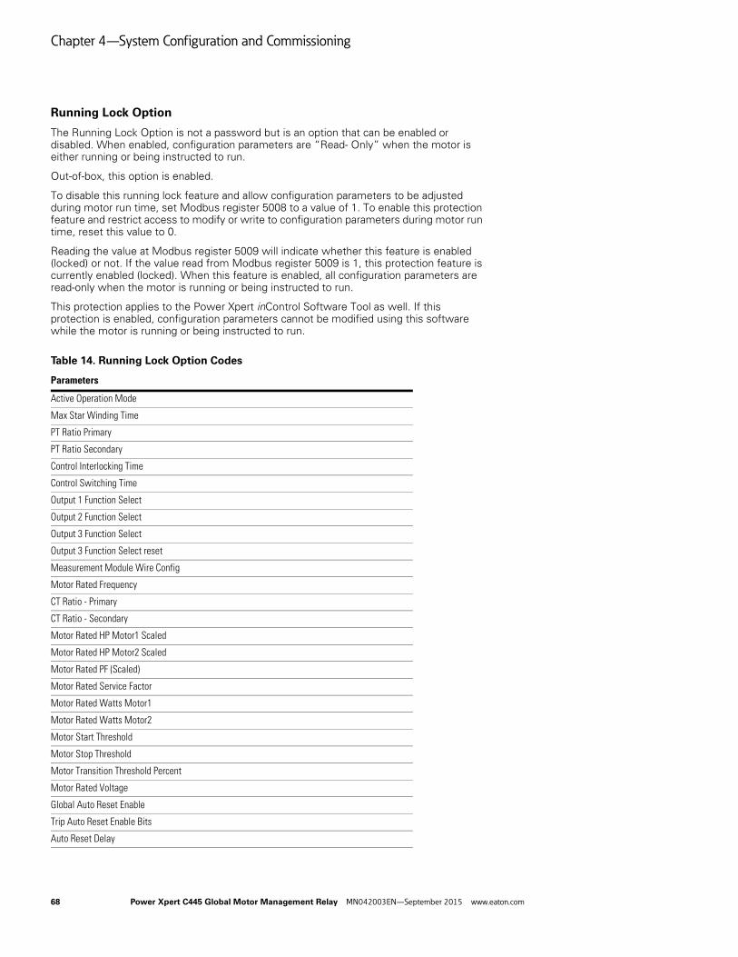
Chapter 4—System Configuration and Commissioning
Running Lock Option
The Running Lock Option is not a password but is an option that can be enabled or disabled. When enabled, configuration parameters are “Read- Only” when the motor is either running or being instructed to run.
Out-of-box, this option is enabled.
To disable this running lock feature and allow configuration parameters to be adjusted during motor run time, set Modbus register 5008 to a value of 1. To enable this protection feature and restrict access to modify or write to configuration parameters during motor run time, reset this value to 0.
Reading the value at Modbus register 5009 will indicate whether this feature is enabled (locked) or not. If the value read from Modbus register 5009 is 1, this protection feature is currently enabled (locked). When this feature is enabled, all configuration parameters are read-only when the motor is running or being instructed to run.
This protection applies to the Power Xpert inControl Software Tool as well. If this protection is enabled, configuration parameters cannot be modified using this software while the motor is running or being instructed to run.
Table 14. Running Lock Option Codes
Parameters
Active Operation Mode
Max Star Winding Time
PT Ratio Primary
PT Ratio Secondary
Control Interlocking Time
Control Switching Time
Output 1 Function Select
Output 2 Function Select
Output 3 Function Select
Output 3 Function Select reset
Measurement Module Wire Config
Motor Rated Frequency
CT Ratio - Primary
CT Ratio - Secondary
Motor Rated HP Motor1 Scaled
Motor Rated HP Motor2 Scaled
Motor Rated PF (Scaled)
Motor Rated Service Factor
Motor Rated Watts Motor1
Motor Rated Watts Motor2
Motor Start Threshold
Motor Stop Threshold
Motor Transition Threshold Percent
Motor Rated Voltage
Global Auto Reset Enable
Trip Auto Reset Enable Bits
Auto Reset Delay
68 Power Xpert C445 Global Motor Management Relay MN042003EN—September 2015 www.eaton.com
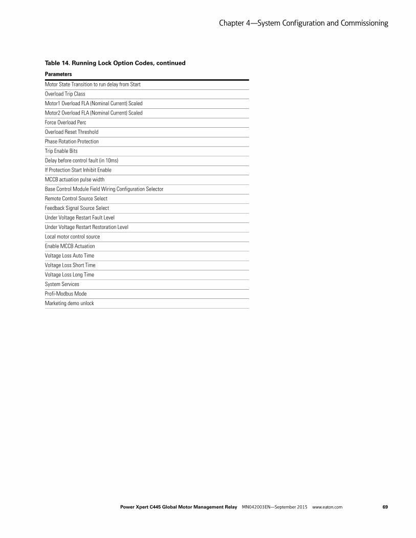
Chapter 4—System Configuration and Commissioning
Motor State Transition to run delay from Start
Overload Trip Class
Motor1 Overload FLA (Nominal Current) Scaled
Motor2 Overload FLA (Nominal Current) Scaled
Force Overload Perc
Overload Reset Threshold
Phase Rotation Protection
Trip Enable Bits
Delay before control fault (in 10ms)
If Protection Start Inhibit Enable
MCCB actuation pulse width
Base Control Module Field Wiring Configuration Selector
Remote Control Source Select
Feedback Signal Source Select
Under Voltage Restart Fault Level
Under Voltage Restart Restoration Level
Local motor control source
Enable MCCB Actuation
Voltage Loss Auto Time
Voltage Loss Short Time
Voltage Loss Long Time
System Services
Profi-Modbus Mode
Marketing demo unlock
Table 14. Running Lock Option Codes, continued
Parameters
Power Xpert C445 Global Motor Management Relay MN042003EN—September 2015 www.eaton.com 69

Chapter 4—System Configuration and Commissioning
Web Pages Password Protection
Only Super-User has the ability to change the User Names and Passwords for the various levels. The web page provides five levels of authorization.
The following is a step by step process demonstrating how to set passwords for the Web Pages.
1. After opening the Web Pages, select user name/password:
LevelDefault User Name
Default Password Description
Open <none> <none> Open access, has no password. Allows opening web page to be viewed, but no additional information is available
Read_Only readonly readonly Read_Only access allows parameters to be viewed, but no control or configuration
Control control control Control provides capabilities of Read_Only plus allows motor and discrete outputs to be turned on and off
Config configuration configuration Config provides capabilities of Control plus the ability to set configuration values
Super_User superuser superuser Super_User provides the capabilities of Config plus the ability to change user names and passwords
70 Power Xpert C445 Global Motor Management Relay MN042003EN—September 2015 www.eaton.com

Chapter 4—System Configuration and Commissioning
2. Enter a user name and password for each level.
Power Xpert C445 Global Motor Management Relay MN042003EN—September 2015 www.eaton.com 71

Chapter 4—System Configuration and Commissioning
3. After entering the username & password, select the Set User/Password button for each level. A successful status message will be displayed per the following:
72 Power Xpert C445 Global Motor Management Relay MN042003EN—September 2015 www.eaton.com

Chapter 4—System Configuration and Commissioning
4. Select an access level to change the access level to something other than Super-User.
5. Select the Control Level then the Change Button and enter a User Name and Password when prompted.
Power Xpert C445 Global Motor Management Relay MN042003EN—September 2015 www.eaton.com 73

Chapter 4—System Configuration and Commissioning
6. Enter the username & password set for Control access level.
7. The following message will be displayed if successful.
8. Repeat this process to change the User Name and Password for other access levels.
Note: User Names and Passwords are case sensitive and must be 6-16 characters in length.
74 Power Xpert C445 Global Motor Management Relay MN042003EN—September 2015 www.eaton.com

Chapter 5—System Configuration and Operation
Chapter 5—System Configuration and Operation
Control Sources
Types
The C445 can be operated from either a Local or a Remote control source. There are four options for the Local Control Source:
● Auto detect User Interface
● No Local Control
● User Interface Control
● Fieldwire Control
Auto detect User Interface—By default the local control source is set to the “Auto detect User Interface” selection. In this selection, if a User Interface module with control buttons is connected, the User Interface will be the Local Control Source. If a Status only User Interface module without control buttons is connected or if no User Interface module is connected at all, the Local Control source will be treated as No Local Control.
No Local Control—Is not allowed, if a User Interface module with control buttons is connected.
User Interface Control—User Interface will be the Local Control Source. If a Status only User Interface module without control buttons is connected or if no User Interface module is connected at all, the system will remain inhibited.
Fieldwire Control—The Fieldwire will act as the Local Control Source. This selection is allowed if a Status only User Interface module without control buttons is connected or if no User Interface module is connected at all. The default wiring method is 2-wire control. 3-wire control is an option for all operation modes except Reverser and the Two-Speed Operation modes. Page 79 displays the wiring options for all modes.
There are three options for the remote control source:
● No remote control source
● Fieldbus
● Fieldwire
No remote control source—Remote Control is not allowed under any condition.
Fieldbus—Fieldbus will be the Remote Control source if the Active Control Source is Remote.
Fieldwire—Fieldwire will be the remote control source if the Active Control Source is Remote. This selection cannot be used if the Fieldwire is already selected as a local control source. The default wiring method is 2-wire control. 3-wire control is an option for all operation modes. Wiring options for all modes are shown later in this chapter.
Active Control Source
The C445 system can have only one active control source at any given point of time. At power up, the control source is determined by the local/remote power up mode setting, which can be set to either remote control, local control or hold last control state. By default the setting is set to hold last control state and out of the box local control will be source of control. The current active control source can be determined by reading the active control source parameter.
Switching Between Local and Remote
Local to RemoteWhen the active control source is local, the following actions will change the active control source to Remote control:
1. Pressing the AUTO button on the User Interface if User Interface is the local control.
2. Setting the REMOTE input on the Fieldwire if the Fieldwire is used as the local control.
3. Setting the Local Control Source to No local Control and the Remote Control Source is not set to No remote control source.
After switching to Remote control, the Remote control source is determined by the Remote Control Source parameter.
Remote to Local When the active control source is remote, the following actions will change the active control source to Local control:
1. Pressing any button on the User Interface except the AUTO and the Reset button.
2. Clearing the REMOTE input on the Fieldwire if the Fieldwire is used as the local control.
After switching to Local control, the Local control source is determined by the Local Control Source parameter.
Power Xpert C445 Global Motor Management Relay MN042003EN—September 2015 www.eaton.com 75

Chapter 5—System Configuration and Operation
Pre-Defined Operation Modes
There are 11 selectable Operation modes for the C445. This section describes the modes in detail. Selecting one of these modes will determine the behavior of the relay’s inputs and outputs.
Active Operation Mode
The Active Operation Mode parameter is used to select the active mode. Any change to this parameter will require a soft reset or power cycle before the new mode takes effect. The following modes are supported:
● Overload Only
● Direct (FVNR)
● Reverser (FVR)
● Star/Delta
● Two Speed Two Winding
● Two Speed Dahlander
● Auto Transformer
● Solenoid Valve
● MCCB Actuation
● Contactor Feeder
● General Purpose Input/Output
76 Power Xpert C445 Global Motor Management Relay MN042003EN—September 2015 www.eaton.com

Chapter 5—System Configuration and Operation
Overload Only Operation Mode
DescriptionThe Overload only mode uses the Motor 1 parameters for all control/protections.
C445 outputs:
● Output 1 is used as the fault contact. It is a normally open contact.
● Outputs 2 and 3 are general purpose outputs
At power up, the C445 Motor Management relay closes Output 1, provided the C445 is in the “Ready” state (no faults or inhibits active). This normally open fault contact provides fail-safe operation in case power is lost.
Outputs 2 and 3 are user configurable outputs that may be used to indicate a Fault, Trip, Motor or Warning status as well as general purpose outputs controlled by the fieldbus master.
The Overload Only Operation mode does not control the contactor/motor, but it does protect it. Per the output wiring diagrams shown later in this section, a control source must be used in series with the normally open fault contact for control.
The only control allowed for this Operation Mode from any of the three potential sources, User Interface, Fieldbus or Fieldwire is to Reset a Fault or Test Trip the unit.
Recommended User Interface Overlays for the Overload Only Operation Mode
Figure 60. C445UC-I9: IEC Control and Status
Figure 61. C445UC-I1: IEC Status Only
Figure 62. C445UC-N9: NEMA Control and Status
Overlay Display:
● OFF LED solid On – Motor is off in “ready” state – no current detected, no faults present
● OFF LED blinking On – Motor is off, C445 control is faulted and/or a control inhibit is present
● RUN LED solid On – Motor is running and is up to speed – complete start detected
● RUN LED blinking On – Motor is running but is NOT up to speed
● AUTO LED Off – C445 control is local source
● AUTO LED On – C445 control is remote source
Overlay Buttons:
● TEST button – Will put the control in “Local” and will cause the C445 to “trip” the overload.
● AUTO button – Selects the remote source as the active C445 control
● RESET button – Resets fault if condition has cleared
Power Xpert C445 Global Motor Management Relay MN042003EN—September 2015 www.eaton.com 77
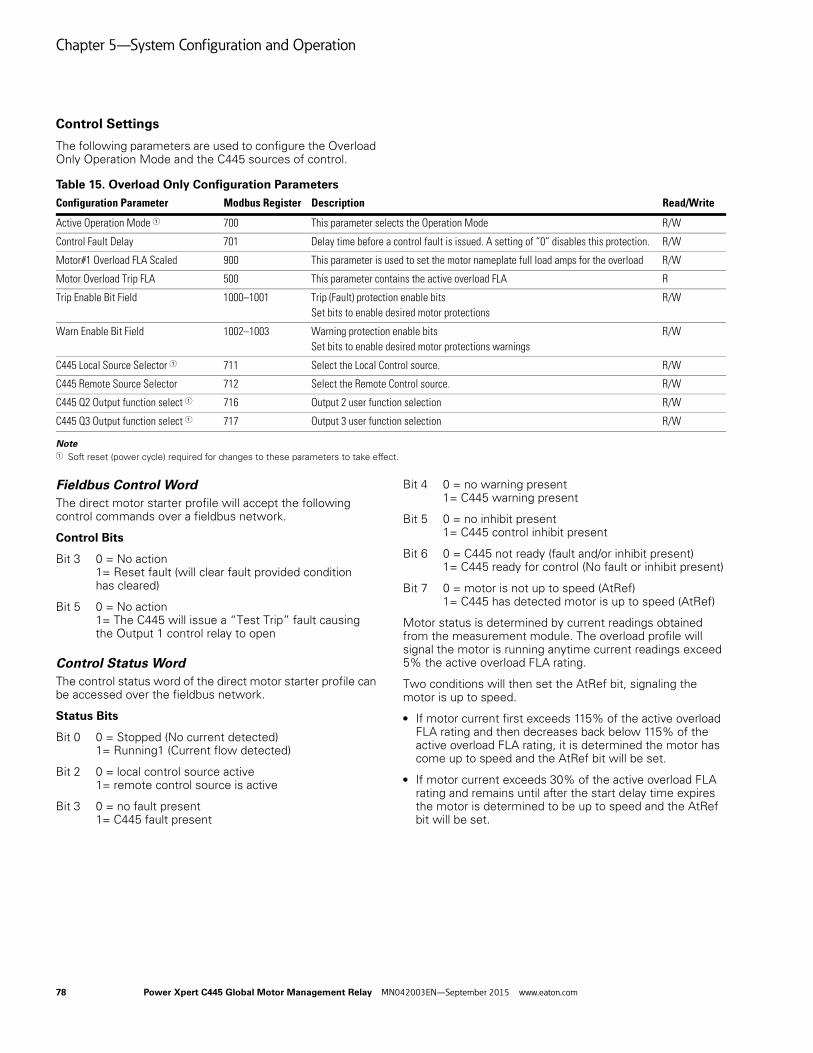
Chapter 5—System Configuration and Operation
Control Settings
The following parameters are used to configure the Overload Only Operation Mode and the C445 sources of control.
Table 15. Overload Only Configuration Parameters
Note1 Soft reset (power cycle) required for changes to these parameters to take effect.
Fieldbus Control WordThe direct motor starter profile will accept the following control commands over a fieldbus network.
Control Bits
Bit 3 0 = No action1= Reset fault (will clear fault provided condition has cleared)
Bit 5 0 = No action1= The C445 will issue a “Test Trip” fault causing the Output 1 control relay to open
Control Status WordThe control status word of the direct motor starter profile can be accessed over the fieldbus network.
Status Bits
Bit 0 0 = Stopped (No current detected)1= Running1 (Current flow detected)
Bit 2 0 = local control source active1= remote control source is active
Bit 3 0 = no fault present1= C445 fault present
Bit 4 0 = no warning present1= C445 warning present
Bit 5 0 = no inhibit present1= C445 control inhibit present
Bit 6 0 = C445 not ready (fault and/or inhibit present)1= C445 ready for control (No fault or inhibit present)
Bit 7 0 = motor is not up to speed (AtRef)1= C445 has detected motor is up to speed (AtRef)
Motor status is determined by current readings obtained from the measurement module. The overload profile will signal the motor is running anytime current readings exceed 5% the active overload FLA rating.
Two conditions will then set the AtRef bit, signaling the motor is up to speed.
● If motor current first exceeds 115% of the active overload FLA rating and then decreases back below 115% of the active overload FLA rating, it is determined the motor has come up to speed and the AtRef bit will be set.
● If motor current exceeds 30% of the active overload FLA rating and remains until after the start delay time expires the motor is determined to be up to speed and the AtRef bit will be set.
Configuration Parameter Modbus Register Description Read/Write
Active Operation Mode 1 700 This parameter selects the Operation Mode R/W
Control Fault Delay 701 Delay time before a control fault is issued. A setting of “0” disables this protection. R/W
Motor#1 Overload FLA Scaled 900 This parameter is used to set the motor nameplate full load amps for the overload R/W
Motor Overload Trip FLA 500 This parameter contains the active overload FLA R
Trip Enable Bit Field 1000–1001 Trip (Fault) protection enable bitsSet bits to enable desired motor protections
R/W
Warn Enable Bit Field 1002–1003 Warning protection enable bitsSet bits to enable desired motor protections warnings
R/W
C445 Local Source Selector 1 711 Select the Local Control source. R/W
C445 Remote Source Selector 712 Select the Remote Control source. R/W
C445 Q2 Output function select 1 716 Output 2 user function selection R/W
C445 Q3 Output function select 1 717 Output 3 user function selection R/W
78 Power Xpert C445 Global Motor Management Relay MN042003EN—September 2015 www.eaton.com

Chapter 5—System Configuration and Operation
Wiring Diagrams for the Overload Only Operation Mode
Figure 63. Isolated 24 Vdc Inputs/24 Vdc Outputs/24 Vdc Power
Figure 64. Non-isolated 24 Vdc Inputs/24 Vdc Outputs/24 Vdc C445 Power
CH1T1 T2
V1 V2 V3
C445M...
I1 I2
C445BD-SD...
CH1CH2
CH1
C445UC...
I3 I4 C 0V 24V Q1 Q1 Q2 Q2 Q3 C Q3 24V 0V PE
C D0 D1
CH2
1 2 3 4 5 6 7 8
PTCMOTOR3~
L2
L3
PE
L1
(+) Us
(-) Us24 VDC
Optional Modbus
F1
Q11
Q1
Q11
RUN
RE
SE
T
RE
MO
TE
TES
T TR
IP
(+) Uc
(-) Uc24 VDC
CH1T1 T2
V1 V2 V3
C445M...
I1 I2
C445BD-SD...
CH1CH2
CH1
C445UC...
I3 I4 C 0V 24V Q1 Q1 Q2 Q2 Q3 C Q3 24V 0V PE
C D0 D1
CH2
1 2 3 4 5 6 7 8
PTCMOTOR3~
L2
L3
PE
L1
(+) Us
(-) Us24 VDC
Optional Modbus
F1
Q11
Q1
RE
SE
T
RE
MO
TE
TES
T TR
IP
Q11
RUN
Power Xpert C445 Global Motor Management Relay MN042003EN—September 2015 www.eaton.com 79

Chapter 5—System Configuration and Operation
Figure 65. 120 Vac Inputs and 120/230 Vac Outputs/C445 Power
Notes:
1. The inputs on the Base Control Module are only used by this Operation Mode if Fieldwire is selected for one of the control sources. If Fieldwire is not the Local or Remote control source, all 4 inputs may be used as general purpose inputs.
2. Outputs 2 and 3 may be used as general purpose outputs for this Operation Mode.
3. If Fieldwire is the Local control source, Input 3 is the Remote input. When power is applied to Input 3, the C445 will be in Remote mode.
4. If Fieldwire is the Remote control source and 2-wire control (default) is selected, Input 3 is unused by this operation mode.
5. If 3-wire control is selected along with Fieldwire for either control source, Input 2 is Permissive.
CH1T1 T2
V1 V2 V3
C445M...
I1 I2
C445BA-SA...
CH1CH2
CH1
C445UC...
I3 I4 IC Q1 Q1 Q2 Q2 Q3 C Q3
C D0 D1
CH2
1 2 3 4 5 6 7 8
PTCMOTOR3~
L2
L3
PE
L1
Optional Modbus
F1
Q11
Q1
PE N L
(+) Us
(-) Us120/240 VAC
IC IC
FB1FERRITER
ES
ET
RE
MO
TE
TES
T TR
IP
Q11
RUN
(+) Uc
(-) Uc120 VAC
80 Power Xpert C445 Global Motor Management Relay MN042003EN—September 2015 www.eaton.com

Chapter 5—System Configuration and Operation
Direct Operation Mode
DescriptionDirect Motor starter is the default profile. The Direct Motor starter profile will use the motor1 parameters for all control/protections.
C445 outputs:
● Output 1 is dedicated by this application mode for controlling and protecting the motor
● Outputs 2 and 3 are general purpose
Output 1 controls and protects the contactor/motor. It will close when a valid RUN command is received by the C445, provided a fault or inhibit is not active and will open on a STOP command or if a trip occurs. A C445 Trip condition will cause the Output contact to open.
Outputs 2 and 3 are user configurable outputs and their function can be selected by the user.
The C445 will issue a control fault when:
● Run command is active and phase voltage is present with no phase current detected after delay expires
● Stop command active and current detected after delay expires
Figure 66. Timing Diagram for the Direct Mode Operation
Recommended User Interface Overlays for the Direct Operation Mode
Figure 67. C445UC-I0: IEC Control and Status
Figure 68. C445UC-I1: IEC Status only
Figure 69. C445UC-I4: IEC Control and Status
Figure 70. C445UC-N0: NEMA Control and Status
Figure 71. C445UC-N1: NEMA Status only
RUN
Control Fault delay
Timing Diagram
Power Xpert C445 Global Motor Management Relay MN042003EN—September 2015 www.eaton.com 81

Chapter 5—System Configuration and Operation
Figure 72. C445UC-N4: NEMA Control and Status
Overlay Display:
● OFF LED solid On – Motor is off in “ready” state – no current detected, no faults present
● OFF LED blinking On – Motor is off, C445 control is faulted and/or a control inhibit is present
● RUN LED solid On – Active RUN1 command and motor is up to speed – complete start detected
● RUN LED blinking On – Active RUN1 command but motor is NOT up to speed
● AUTO LED Off – C445 control is local source
● AUTO LED On – C445 control is remote source
Overlay Buttons:
● OFF button – Button press will put the control in “Local” and will send a STOP command to the C445 overload to drop out the starter.
● RUN button – Button press will put the control in “Local” and will send a RUN1 command to the C445 overload to start the starter.
● AUTO button – Selects the remote source as the active C445 control
● RESET button – Resets fault if condition has cleared
● HAND button – Button press will put the control in “Local” and will send a RUN1 command to the C445 overload to start the starter.
82 Power Xpert C445 Global Motor Management Relay MN042003EN—September 2015 www.eaton.com

Chapter 5—System Configuration and Operation
Control Settings
The following parameters are used to configure the Direct Operation Mode and the C445 sources of control.
Table 16. Direct Configuration Parameters
Note1 Soft reset (power cycle) required for changes to these parameters to take effect.
Fieldbus Control WordThe direct motor starter profile will accept the following control commands over a fieldbus network.
Control Bits
Bit 0 0 = Stop command, de-activate all control outputs1 = Run1 command, activate Output 1
Bit 3 0 = No action1= Reset fault (will clear fault provided condition has cleared)
Bit 5 0 = No action1= The C445 will issue a “Test Trip” fault causing the Output 1 control relay to open
Control Status WordThe control status word of the direct motor starter profile can be accessed over the fieldbus network.
Status Bits
Bit 0 0 = Stopped (No active Run1 command)1= Running1 (Run1 command is present)
Bit 2 0 = local control source active1= remote control source is active
Bit 3 0 = no fault present1= C445 fault present
Bit 4 0 = no warning present1= C445 warning present
Bit 5 0 = no inhibit present1= C445 control inhibit present
Bit 6 0 = C445 not ready (fault and/or inhibit present)1= C445 ready for control (No fault or inhibit present)
Bit 7 0 = motor is not up to speed (AtRef)1= C445 has detected motor is up to speed (AtRef)
Motor status is determined by current readings obtained from the measurement module. The overload profile will signal the motor is running anytime current readings exceed 5% the active overload FLA rating.
Two conditions will then set the AtRef bit, signaling the motor is up to speed.
● If motor current first exceeds 115% of the active overload FLA rating and then decreases back below 115% of the active overload FLA rating, it is determined the motor has come up to speed and the AtRef bit will be set.
● If motor current exceeds 30% of the active overload FLA rating and remains until after the start delay time expires the motor is determined to be up to speed and the AtRef bit will be set.
Configuration Parameter Modbus Register Description Read/Write
Active Operation Mode 1 700 This parameter selects the Operation Mode R/W
Control Fault Delay 701 Delay time before a control fault is issued. A setting of “0” disables this protection. R/W
Motor#1 Overload FLA Scaled 900 This parameter is used to set the motor nameplate full load amps for the overload R/W
Motor Overload Trip FLA 500 This parameter contains the active overload FLA R
Trip Enable Bit Field 1000-1001 Trip (Fault) protection enable bitsSet bits to enable desired motor protections
R/W
Warn Enable Bit Field 1002-1003 Warning protection enable bitsSet bits to enable desired motor protections warnings
R/W
C445 Local Source Selector 1 711 Select the Local Control source. R/W
C445 Remote Source Selector 712 Select the Remote Control source. R/W
C445 Q2 Output function select 1 716 Output 2 user function selection R/W
C445 Q3 Output function select 1 717 Output 3 user function selection R/W
Power Xpert C445 Global Motor Management Relay MN042003EN—September 2015 www.eaton.com 83

Chapter 5—System Configuration and Operation
Wiring Diagrams for the Direct Operation Mode
Figure 73. Isolated 24 Vdc Inputs/24 Vdc Outputs/24 Vdc Power
Figure 74. Non-isolated 24 Vdc Inputs/24 Vdc Outputs/24 Vdc C445 Power
CH1T1 T2
V1 V2 V3
C445M...
I1 I2
C445BD-SD...
CH1CH2
CH1
C445UC...
I3 I4 C 0V 24V Q1
CH2
1 2 3 4 5 6 7 8
PTCMOTOR3~
L2
L3
PE
L1
F1
Q11
Q1
Q1 Q2 Q2R
ES
ET
RE
MO
TE
RU
N
Q11
Q3 C Q3 24V 0V PE
C D0 D1
(+) Us
(-) Us24 VDC
Optional Modbus
(+) Uc
(-) Uc24 VDC
RU
N
CH1T1 T2
V1 V2 V3
C445M...
I1 I2
C445BD-SD...
CH1CH2
CH1
C445UC...
I3 I4 C 0V 24V Q1 Q1 Q2 Q2 Q3 C Q3 24V 0V PE
C D0 D1
CH2
1 2 3 4 5 6 7 8
PTCMOTOR3~
L2
L3
PE
L1
(+) Us
(-) Us24 VDC
Optional Modbus
F1
Q11
Q1
Q11
RE
SE
T
RE
MO
TE
84 Power Xpert C445 Global Motor Management Relay MN042003EN—September 2015 www.eaton.com

Chapter 5—System Configuration and Operation
Figure 75. 120 Vac Inputs and 120/230 Vac Outputs/C445 Power
Notes:
1. The inputs on the Base Control Module are only used by this Operation Mode if Fieldwire is selected for one of the control sources. If Fieldwire is not the Local or Remote control source, all 4 inputs may be used as general purpose inputs.
2. Outputs 2 and 3 may be used as general purpose outputs for this Operation Mode.
3. If Fieldwire is the Local control source, Input 3 is the Remote input. When power is applied to Input 3, the C445 will be in Remote mode.
4. If Fieldwire is the Remote control source and 2-wire control (default) is selected, Input 3 is unused by this operation mode.
5. If 3-wire control is selected along with Fieldwire for either control source, Input 2 is Permissive.
Q11
CH1T1 T2
V1 V2 V3
C445M...
I1 I2
C445BA-SA...
CH1CH2
CH1
C445UC...
I3 I4 IC Q1 Q1 Q2 Q2 Q3 C Q3
C D0 D1
CH2
1 2 3 4 5 6 7 8
PTCMOTOR3~
L2
L3
PE
L1
Optional Modbus
F1
Q11
Q1
PE N LIC IC
(+) Us
(-) Us120/240 VAC
FB1FERRITER
ES
ET
RE
MO
TE
RU
N
(+) Uc
(-) Uc120 VAC
Power Xpert C445 Global Motor Management Relay MN042003EN—September 2015 www.eaton.com 85

Chapter 5—System Configuration and Operation
Reverser Operation Mode
DescriptionThe Reverser starter profile will use the motor1 parameters for all control/protections.
C445 outputs:
● Output 1 is configured as the FWD relay output● Output 2 is configured as the REV relay output● Output 3 is general purpose
Output 1 controls the FORWARD contactor. Output 1 will close when a valid FWD(RUN1) command is received and there is no active fault or inhibit.
It will open on a STOP command or if a trip occurs.
Output 2 controls the REVERSE contactor. Output 2 will close anytime a valid REV(RUN2) command is received and there is no active fault or inhibit. It will open on a STOP command or if a trip occurs.
A C445 trip will cause Outputs 1 and 2 to open effectively dropping out the reverser.
Output 3 is a user configurable output whose function can be changed by the user.
A transition from FWD to REV or REV to FWD must first go through STOP unless the Control Interlocking Time parameter is set to a value of 0. If the value of this parameter is greater than 0, the control will transition to Stop for that delay time before transitioning to the new direction. The Control Interlocking Time parameter can be found in the Operation mode category in the Power Xpert inControl Software Tool.
The C445 will issue a control fault when:● RunFwd or RunRev command is active and phase voltage
is present with no phase current detected after delay expires
● Stop command active and current detected after delay expires
Note: Even with the control fault disabled, the C445 will NOT transition to a new direction until current readings decrease to zero.
Figure 76. Timing Diagram for the Reverse Operation Mode
Recommended User Interface Overlays for the Reverser Operation Mode
Figure 77. C445UC-I3: IEC Control and Status
Figure 78. C445UC-I5: IEC Control and Status
Figure 79. C445UC-N2: NEMA Status Only
Figure 80. C445UC-N5: NEMA Control and Status
FWD
REV
Interlock Time
Timing Diagram
Control Fault Delay
86 Power Xpert C445 Global Motor Management Relay MN042003EN—September 2015 www.eaton.com

Chapter 5—System Configuration and Operation
Overlay Display:
● OFF LED solid On – Motor is off in “ready” state – no current detected, no faults present
● OFF LED blinking On – Motor is off, C445 control is faulted and/or a control inhibit is present
● FWD/REV LED solid On – Active RUN command and motor is up to speed – complete start detected
● FWD/REV blinking On – Active RUN command but motor is NOT up to speed
● AUTO LED Off – C445 control is local source
● AUTO LED On – C445 control is remote source
Overlay Buttons:
● OFF button – Button press will put the control in “Local” and will send a STOP command to the C445 overload which will drop out all control outputs and stop the motor.
● FWD button – Button press will put the control in “Local” and will send a FWD RUN command to the C445 overload to enable the forward output relay (Q1).
● REV button – Button press will put the control in “Local” and will send a REV RUN command to the C445 overload to enable the reverse output relay (Q2).
● AUTO button – Selects the remote source as the active C445 control
● RESET button – Resets fault if condition has cleared
Power Xpert C445 Global Motor Management Relay MN042003EN—September 2015 www.eaton.com 87

Chapter 5—System Configuration and Operation
Control Settings
The following parameters are used to configure the Reverser Operation Mode and the C445 sources of control.
Table 17. Reverser Configuration Parameters
Note1 Soft reset (power cycle) required for changes to these parameters to take effect.
Fieldbus Control WordThe reverser motor starter profile will accept the following control commands over a fieldbus network.
Control Bits
Bit 0/1 00 = Stop command, de-activate all control outputs01 = Run FWD command, activate Output 110 = Run REV command, activate Output 211 = Unknown command, No action
Bit 3 0 = No action1= Reset fault (will clear fault provided condition has cleared)
Bit 5 0 = No action1= The C445 will issue a “Test Trip” fault causing the Output 1 & Output 2 control relays to open.
Control Status WordThe control status word of the reverser motor starter profile can be accessed over the fieldbus network.
Status Bits
Bit 0/1 00 = Stopped (No active Run commands)01= Running1 (Run FWD command is active)10= Running2 (Run REV command is active)
Bit 2 0 = local control source active1= remote control source is active
Bit 3 0 = no fault present1= C445 fault present
Bit 4 0 = no warning present1= C445 warning present
Bit 5 0 = no inhibit present1= C445 control inhibit present
Bit 6 0 = C445 not ready (fault and/or inhibit present)1= C445 ready for control (No fault or inhibit present)
Bit 7 0 = motor is not up to speed (AtRef)1= C445 has detected motor is up to speed (AtRef)
Two conditions will set the AtRef bit, signaling the motor is up to speed.
● If motor current first exceeds 115% of the active overload FLA rating and then decreases back below 115% of the active overload FLA rating, it is determined the motor has come up to speed and the AtRef bit will be set.
● If motor current exceeds 30% of the active overload FLA rating and remains until after the start delay time expires the motor is determined to be up to speed and the AtRef bit will be set.
Configuration Parameter Modbus Register Description Read/Write
Active Operation Mode 1 700 This parameter selects the Operation Mode R/W
Control Fault Delay 701 Delay time before a control fault is issued. A setting of “0” disables protection. R/W
Control Interlock Time Delay 702 Time delay before change of direction allowed R/W
Motor#1 Overload FLA Scaled 900 This parameter is used to set the motor nameplate full load amps for the overload R/W
Motor Overload Trip FLA 500 This parameter contains the active overload FLA R
Trip Enable Bit Field 1000-1001 Trip (Fault) protection enable bitsSet bits to enable desired motor protections
R/W
Warn Enable Bit Field 1002-1003 Warning protection enable bitsSet bits to enable desired motor protections warnings
R/W
C445 Local Source Selector 1 711 Select the Local Control source. R/W
C445 Remote Source Selector 712 Select the Remote Control source. R/W
C445 Q3 Output function select 1 717 Output 3 user function selection R/W
88 Power Xpert C445 Global Motor Management Relay MN042003EN—September 2015 www.eaton.com

Chapter 5—System Configuration and Operation
Wiring Diagrams for the Reverse Operation Mode
Figure 81. Isolated 24 Vdc Inputs/24 Vdc Outputs/24 Vdc Power
Figure 82. Non-isolated 24 Vdc Inputs/24 Vdc Outputs/24 Vdc C445 Power
RE
SE
T
RE
MO
TE
FOR
WA
RD
RE
VE
RS
ECH1T1 T2
V1 V2 V3
C445M...
I1 I2
C445BD-SD...
CH1CH2
CH1
C445UC...
I3 I4 C 0V 24V Q1 Q1 Q2 Q2 Q3 C Q3 24V 0V PE
C D0 D1
CH2
1 2 3 4 5 6 7 8
MOTOR3~
L2
L3
PE
L1
(+) Us
(-) Us24 VDC
Optional Modbus
F1
Q11FWD
Q1
Q11
Q12REV
PTC
Q12
(+) Uc
(-) Uc24 VDC
Q12 Q11
RE
SE
T
RE
MO
TE
FOR
WA
RD
RE
VE
RS
E
CH1T1 T2
V1 V2 V3
C445M...
I1 I2
C445BD-SD...
CH1CH2
CH1
C445UC...
I3 I4 C 0V 24V Q1 Q1 Q2 Q2 Q3 C Q3 24V 0V PE
C D0 D1
CH2
1 2 3 4 5 6 7 8
L2
L3
PE
L1
Optional Modbus
F1
Q1
MOTOR3~
(+) Us
(-) Us24 VDC
Q11FWD
Q11
Q12REV
PTC
Q12
Q12 Q11
Power Xpert C445 Global Motor Management Relay MN042003EN—September 2015 www.eaton.com 89
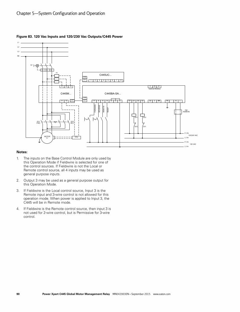
Chapter 5—System Configuration and Operation
Figure 83. 120 Vac Inputs and 120/230 Vac Outputs/C445 Power
Notes:
1. The inputs on the Base Control Module are only used by this Operation Mode if Fieldwire is selected for one of the control sources. If Fieldwire is not the Local or Remote control source, all 4 inputs may be used as general purpose inputs.
2. Output 3 may be used as a general purpose output for this Operation Mode.
3. If Fieldwire is the Local control source, Input 3 is the Remote input and 3-wire control is not allowed for this operation mode. When power is applied to Input 3, the C445 will be in Remote mode.
4. If Fieldwire is the Remote control source, then input 3 is not used for 2-wire control, but is Permissive for 3-wire control.
RE
SE
T
RE
MO
TE
FOR
WA
RD
RE
VE
RS
ECH1T1 T2
V1 V2 V3
C445M...
I1 I2
C445BA-SA...
CH1CH2
CH1
C445UC...
I3 I4 IC IC IC
CH2
1 2 3 4 5 6 7 8
L2
L3
PE
L1
F1
Q1
Q1 Q1 Q2 Q2 Q3 C Q3
C D0 D1
Optional Modbus
PE N L
MOTOR3~
Q11FWD
Q11
Q12REV
PTC
Q12
Q12 Q11
(+) Us
(-) Us120/240 VAC
FB1FERRITE
(+) Uc
(-) Uc120 VAC
90 Power Xpert C445 Global Motor Management Relay MN042003EN—September 2015 www.eaton.com
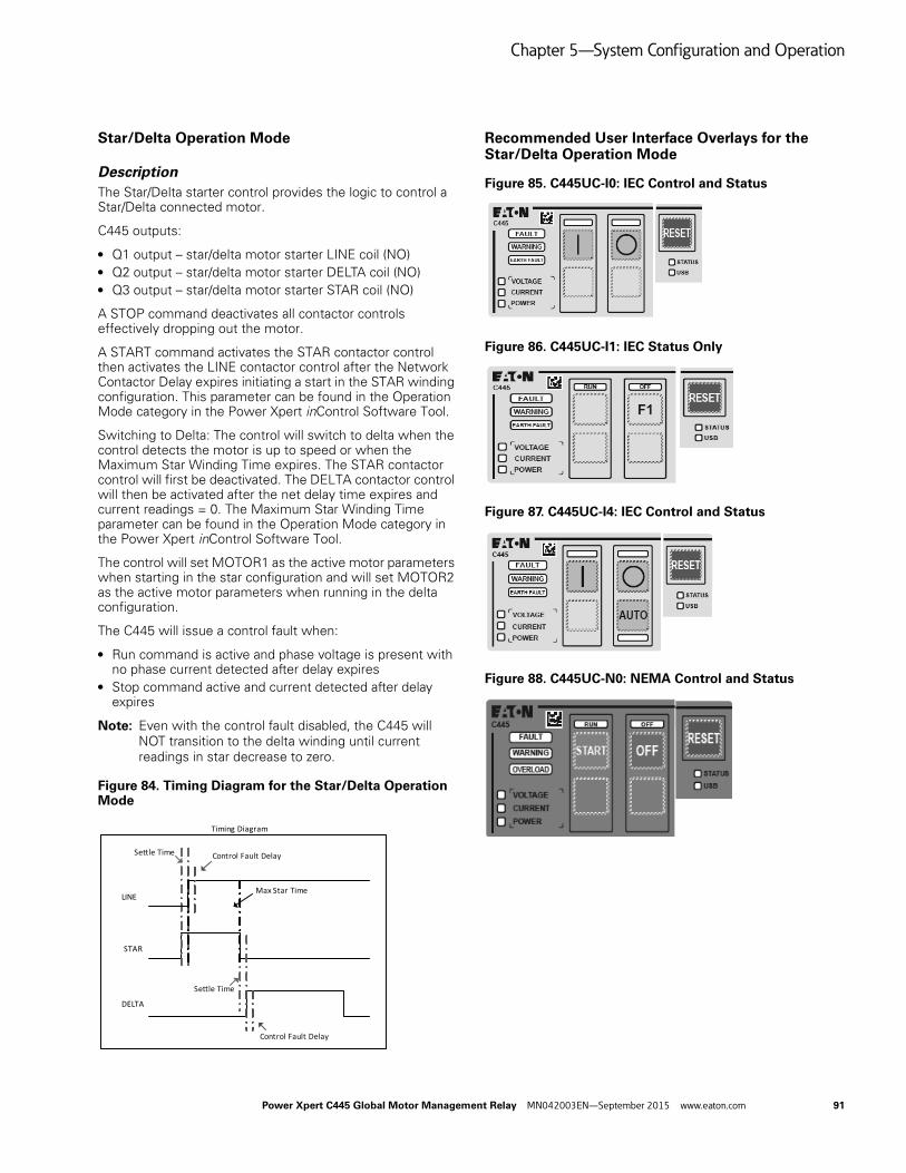
Chapter 5—System Configuration and Operation
Star/Delta Operation Mode
DescriptionThe Star/Delta starter control provides the logic to control a Star/Delta connected motor.
C445 outputs:
● Q1 output – star/delta motor starter LINE coil (NO) ● Q2 output – star/delta motor starter DELTA coil (NO)● Q3 output – star/delta motor starter STAR coil (NO)
A STOP command deactivates all contactor controls effectively dropping out the motor.
A START command activates the STAR contactor control then activates the LINE contactor control after the Network Contactor Delay expires initiating a start in the STAR winding configuration. This parameter can be found in the Operation Mode category in the Power Xpert inControl Software Tool.
Switching to Delta: The control will switch to delta when the control detects the motor is up to speed or when the Maximum Star Winding Time expires. The STAR contactor control will first be deactivated. The DELTA contactor control will then be activated after the net delay time expires and current readings = 0. The Maximum Star Winding Time parameter can be found in the Operation Mode category in the Power Xpert inControl Software Tool.
The control will set MOTOR1 as the active motor parameters when starting in the star configuration and will set MOTOR2 as the active motor parameters when running in the delta configuration.
The C445 will issue a control fault when:
● Run command is active and phase voltage is present with no phase current detected after delay expires
● Stop command active and current detected after delay expires
Note: Even with the control fault disabled, the C445 will NOT transition to the delta winding until current readings in star decrease to zero.
Figure 84. Timing Diagram for the Star/Delta Operation Mode
Recommended User Interface Overlays for the Star/Delta Operation Mode
Figure 85. C445UC-I0: IEC Control and Status
Figure 86. C445UC-I1: IEC Status Only
Figure 87. C445UC-I4: IEC Control and Status
Figure 88. C445UC-N0: NEMA Control and Status
LINE
STAR
Timing Diagram
DELTA
Settle Time
Settle Time
Control Fault Delay
Control Fault Delay
Max Star Time
Power Xpert C445 Global Motor Management Relay MN042003EN—September 2015 www.eaton.com 91

Chapter 5—System Configuration and Operation
Figure 89. C445UC-N1: NEMA Status Only
Figure 90. C445UC-N4: NEMA Control and Status
Overlay Display:
● OFF LED solid On – Motor is off in “ready” state – no current detected, no faults present
● OFF LED blinking On – Motor is off, C445 control is faulted and/or a control inhibit is present
● RUN LED solid On – Active RUN1 command and motor is up to speed – complete start detected
● RUN LED blinking On – Active RUN1 command but motor is NOT up to speed
● AUTO LED Off – C445 control is local source
● AUTO LED On – C445 control is remote source
Overlay Buttons:
● OFF button – Button press will put the control in “Local” and will send a STOP command to the C445 overload to drop out the starter.
● RUN button – Button press will put the control in “Local” and will send a RUN1 command to the C445 overload to start the starter.
● AUTO button – Selects the remote source as the active C445 control
● RESET button – Resets fault if condition has cleared
● HAND button – Button press will put the control in “Local” and will send a RUN1 command to the C445 overload to start the starter.
92 Power Xpert C445 Global Motor Management Relay MN042003EN—September 2015 www.eaton.com

Chapter 5—System Configuration and Operation
Control Settings
The following parameters are used to configure the Star/Delta Operation Mode and the C445 sources of control.
Table 18. Star/Delta Configuration Parameters
Note1 Soft reset (power cycle) required for changes to these parameters to take effect.
Fieldbus Control WordThe star/delta motor starter profile will accept the following control commands over a fieldbus network.
Control Bits
Bit 0 0 = Stop command, de-activate all control outputs1 = Run1 command, begin start sequence
Bit 3 0 = No action1= Reset fault (will clear fault provided condition has cleared)
Bit 5 0 = No action1= The C445 will issue a “Test Trip” fault causing the Outputs 1-3 control relays to open
Control Status WordThe control status word of the direct motor starter profile can be accessed over the fieldbus network.
Status Bits
Bit 0 0 = Stopped (No active Run1 command)1= Running1 (Run1 command is present)
Bit 2 0 = local control source active1= remote control source is active
Bit 3 0 = no fault present1= C445 fault present
Bit 4 0 = no warning present1= C445 warning present
Bit 5 0 = no inhibit present1= C445 control inhibit present
Bit 6 0 = C445 not ready (fault and/or inhibit present)1= C445 ready for control (No fault or inhibit present)
Bit 7 0 = motor is not up to speed (AtRef)1= C445 has detected motor is up to speed on delta winding (AtRef)
Two conditions will set the AtRef bit, signaling the motor is up to speed.
● After transitioning to the delta winding, if motor current increases above 115% of the active overload FLA rating and then decreases back below 115% of the active overload FLA rating, it is determined the motor has come up to speed and the AtRef bit will be set.
● After transitioning to the delta winding, if motor current exceeds 30% of the active overload FLA rating and remains until after the start delay time expires the motor is determined to be up to speed and the AtRef bit will be set.
Configuration Parameter Modbus Register Description Read/Write
Active Operation Mode 1 700 This parameter selects the Operation Mode R/W
Control Fault Delay 701 Delay time before a control fault is issued. A setting of “0” disables this protection. R/W
Network Contactor Settle Time 704 Settle delay time before 2nd contactor is activated – ensures the first contactor is sealed in before applying the line
R/W
Maximum Star Winding Time 705 Maximum time the control will stay on the star winding before transitioning to the delta winding in 100ms
R/W
Motor#1 Overload FLA Scaled 900 This parameter is to set the overload full load amp rating when on the star winding R/W
Motor#2 Overload FLA Scaled 901 This parameter is to set the overload full load amp rating when on the delta winding R/W
Motor Overload Trip FLA 500 This parameter contains the active motor overload FLA (will contain the motor1 setting when on the star winding and the motor2 setting when on the delta winding)
R
Trip Enable Bit Field 1000-1001 Trip (Fault) protection enable bitsSet bits to enable desired motor protections
R/W
Warn Enable Bit Field 1002-1003 Warning protection enable bitsSet bits to enable desired motor protections warnings
R/W
C445 Local Source Selector 1 711 Select the Local Control source. R/W
C445 Remote Source Selector 712 Select the Remote Control source. R/W
Power Xpert C445 Global Motor Management Relay MN042003EN—September 2015 www.eaton.com 93

Chapter 5—System Configuration and Operation
Wiring Diagrams for the Star/Delta Operation Mode
Figure 91. Isolated 24 Vdc Inputs/24 Vdc Outputs/24 Vdc Power
Figure 92. Non-isolated 24 Vdc Inputs/24 Vdc Outputs/24 Vdc C445 Power
RE
SE
T
RE
MO
TE
RU
NCH1T1 T2
V1 V2 V3
C445M...
I1 I2
C445BD-SD...
CH1CH2
CH1
C445UC...
I3 I4 C 0V 24V Q1 Q1 Q2 Q2 Q3 C Q3 24V 0V PE
C D0 D1
CH2
1 2 3 4 5 6 7 8
L2
L3
PE
L1
Optional Modbus
F1
Q1
MOTOR3~
Q11LINE
Q12DELTA
PTC
Q13STAR
1
23
4
56
(+) Us
(-) Us24 VDC
Q11 Q12
(+) Uc
(-) Uc24 VDC
Q13
Q13
Q12
RE
SE
T
RE
MO
TE
RU
N
CH1T1 T2
V1 V2 V3
C445M...
I1 I2
C445BD-SD...
CH1CH2
CH1
C445UC...
I3 I4 C 0V 24V Q1 Q1 Q2 Q2 Q3 C Q3 24V 0V PE
C D0 D1
CH2
1 2 3 4 5 6 7 8
L2
L3
PE
L1
Optional Modbus
F1
Q1
MOTOR3~
Q11LINE
Q12DELTA
PTC
Q13STAR
1
23
4
56
(+) Us
(-) Us24 VDC
Q11 Q12
Q13
Q13
Q12
94 Power Xpert C445 Global Motor Management Relay MN042003EN—September 2015 www.eaton.com

Chapter 5—System Configuration and Operation
Figure 93. 120 Vac Inputs and 120/230 Vac Outputs/C445 Power
Notes:
1. The inputs on the Base Control Module are only used by this Operation Mode if Fieldwire is selected for one of the control sources. If Fieldwire is not the Local or Remote control source, all 4 inputs may be used as general purpose inputs.
2. No outputs may be used as general purpose outputs for this Operation Mode.
3. If Fieldwire is the Local control source, Input 3 is the Remote input. When power is applied to Input 3, the C445 will be in Remote mode.
4. If Fieldwire is the Remote control source and 2-wire control (default) is selected, Input 3 is unused by this operation mode.
5. If 3-wire control is selected along with Fieldwire for either control source, Input 2 is Permissive.
RE
SE
T
RE
MO
TE
RU
N
CH1T1 T2
V1 V2 V3
C445M...
I1 I2
C445BA-SA...
CH1CH2
CH1
C445UC...
I3 I4 IC Q1 Q1 Q2 Q2 Q3 C Q3
C D0 D1
CH2
1 2 3 4 5 6 7 8
L2
L3
PE
L1
Optional Modbus
F1
Q1
PE N LIC IC
MOTOR3~
Q11LINE
Q12DELTA
PTC
Q13STAR
1
23
4
56
Q11 Q12
Q13
Q13
Q12
(+) Us
(-) Us120/240 VAC
(+) Uc
(-) Uc120 VAC
FB1FERRITE
Power Xpert C445 Global Motor Management Relay MN042003EN—September 2015 www.eaton.com 95

Chapter 5—System Configuration and Operation
Two Speed Two Winding Operation Mode
DescriptionThe two speed motor starter operation mode accepts off/slow/fast commands to control two speed motor applications. A run slow command will activate Output 1(slow). A run fast command will activate Output 2(fast). A stop command de-activates both of the outputs.
When transitioning from fast -> slow, the C445 will de-activate Output 2(fast) and will delay activating Output 1(slow) until the Control Switching Time expires, allowing the motor time to slow down before transitioning to the slow speed. The Control Switching Time parameter can be found in the Operation Mode category in the Power Xpert inControl Software Tool.
The C445 will issue a control fault when:
● The RunSlow or RunFast command is active and phase voltage is present and no phase current is detected.
● A Stop command is active and current is detected.
Note: Even with the control fault disabled, after de-activating the present speed, the C445 will NOT transition to the new speed until current readings decrease to zero.
● Outputs 1 and 2 will be de-activated anytime the C445 experiences a fault/inhibit condition.
● Output 1 – slow starter coil (NO)
● Output 2 – fast starter coil (NO)
● Output 3 – open for user configuration and function can be selected by the user.
The AtRef (At Reference) bit in the Motor Control Status register is set based on the following two conditions. At Reference signals that the motor is up to speed.
1. If motor current first exceeds 115% of the active overload FLA rating and then decreases back below 115% of the active overload FLA rating, it is determined the motor has come up to speed and the AtRef bit will be set.
2. If motor current exceeds 30% of the active overload FLA rating and remains until after the Motor State Transition to Run Delay from Start time expires the motor is determined to be up to speed and the AtRef bit will be set. This time delay parameter can be found in the General Protections category in the Power Xpert inControl Software Tool.
Figure 94. Timing Diagram for the Two Speed Operation Mode
SLOW
FAST
Speed Transition Delay
Timing Diagram
Check for motor current = 0
Control Fault Delay
96 Power Xpert C445 Global Motor Management Relay MN042003EN—September 2015 www.eaton.com

Chapter 5—System Configuration and Operation
Recommended User Interface Overlays for the Two Speed Two Winding Operation Mode
Figure 95. C445UC-I2: IEC Control and Status
Figure 96. C445UC-I6: IEC Control and Status
Figure 97. C445UC-N3: NEMA Status Only
Figure 98. C445UC-N6: NEMA Control and Status
Overlay Display:
● OFF LED solid On – Motor is off in “ready” state – no current detected, no faults present
● OFF LED blinking On – Motor is off, C445 control is faulted and/or a control inhibit is present
● SLOW/FAST LED solid On – Active RUN command and motor is up to speed – complete start detected
● SLOW/FAST blinking On – Active RUN command but motor is NOT up to speed
● AUTO LED Off – C445 control is local source
● AUTO LED On – C445 control is remote source
Overlay Buttons:
● OFF button – Button press will put the control in “Local” and will send a STOP command to the C445 which will drop out all control outputs and stop the motor.
● SLOW button – Button press will put the control in “Local” and will send a RUN SLOW command to the C445 to start the motor in slow mode.
● FAST button – Button press will put the control in “Local” and will send a RUN FAST command to the C445 to start the motor in fast mode.
● AUTO button – Selects the remote source as the active C445 control.
Power Xpert C445 Global Motor Management Relay MN042003EN—September 2015 www.eaton.com 97
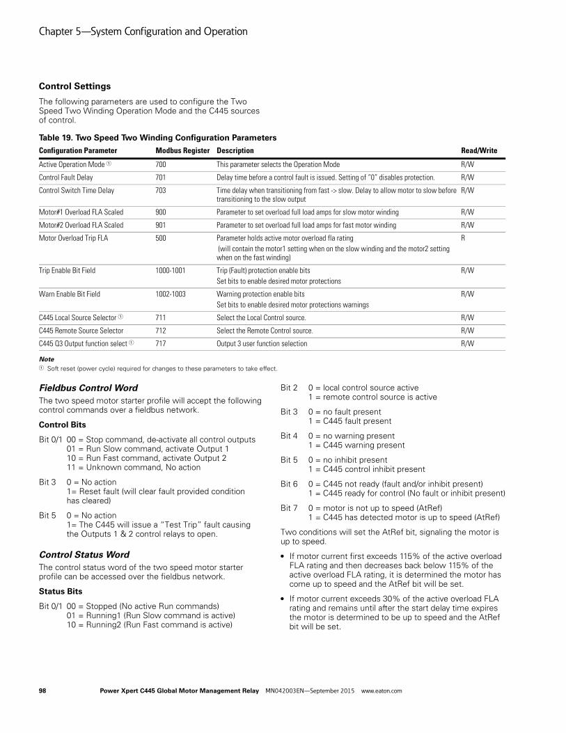
Chapter 5—System Configuration and Operation
Control Settings
The following parameters are used to configure the Two Speed Two Winding Operation Mode and the C445 sources of control.
Table 19. Two Speed Two Winding Configuration Parameters
Note1 Soft reset (power cycle) required for changes to these parameters to take effect.
Fieldbus Control WordThe two speed motor starter profile will accept the following control commands over a fieldbus network.
Control Bits
Bit 0/1 00 = Stop command, de-activate all control outputs01 = Run Slow command, activate Output 110 = Run Fast command, activate Output 211 = Unknown command, No action
Bit 3 0 = No action1= Reset fault (will clear fault provided condition has cleared)
Bit 5 0 = No action1= The C445 will issue a “Test Trip” fault causing the Outputs 1 & 2 control relays to open.
Control Status WordThe control status word of the two speed motor starter profile can be accessed over the fieldbus network.
Status Bits
Bit 0/1 00 = Stopped (No active Run commands)01 = Running1 (Run Slow command is active)10 = Running2 (Run Fast command is active)
Bit 2 0 = local control source active1 = remote control source is active
Bit 3 0 = no fault present1 = C445 fault present
Bit 4 0 = no warning present1 = C445 warning present
Bit 5 0 = no inhibit present1 = C445 control inhibit present
Bit 6 0 = C445 not ready (fault and/or inhibit present)1 = C445 ready for control (No fault or inhibit present)
Bit 7 0 = motor is not up to speed (AtRef)1 = C445 has detected motor is up to speed (AtRef)
Two conditions will set the AtRef bit, signaling the motor is up to speed.
● If motor current first exceeds 115% of the active overload FLA rating and then decreases back below 115% of the active overload FLA rating, it is determined the motor has come up to speed and the AtRef bit will be set.
● If motor current exceeds 30% of the active overload FLA rating and remains until after the start delay time expires the motor is determined to be up to speed and the AtRef bit will be set.
Configuration Parameter Modbus Register Description Read/Write
Active Operation Mode 1 700 This parameter selects the Operation Mode R/W
Control Fault Delay 701 Delay time before a control fault is issued. Setting of “0” disables protection. R/W
Control Switch Time Delay 703 Time delay when transitioning from fast -> slow. Delay to allow motor to slow before transitioning to the slow output
R/W
Motor#1 Overload FLA Scaled 900 Parameter to set overload full load amps for slow motor winding R/W
Motor#2 Overload FLA Scaled 901 Parameter to set overload full load amps for fast motor winding R/W
Motor Overload Trip FLA 500 Parameter holds active motor overload fla rating (will contain the motor1 setting when on the slow winding and the motor2 setting when on the fast winding)
R
Trip Enable Bit Field 1000-1001 Trip (Fault) protection enable bitsSet bits to enable desired motor protections
R/W
Warn Enable Bit Field 1002-1003 Warning protection enable bitsSet bits to enable desired motor protections warnings
R/W
C445 Local Source Selector 1 711 Select the Local Control source. R/W
C445 Remote Source Selector 712 Select the Remote Control source. R/W
C445 Q3 Output function select 1 717 Output 3 user function selection R/W
98 Power Xpert C445 Global Motor Management Relay MN042003EN—September 2015 www.eaton.com

Chapter 5—System Configuration and Operation
Wiring Diagrams for the Two Speed Two Winding Operation Mode
Figure 99. Isolated 24 Vdc Inputs/24 Vdc Outputs/24 Vdc Power
Figure 100. Non-isolated 24 Vdc Inputs/24 Vdc Outputs/24 Vdc C445 Power
RE
SE
T
RE
MO
TE
SLO
W
FAS
T
CH1T1 T2
V1 V2 V3
C445M...
L2
L3
PE
L1
F1
Q1
MOTOR3~
Q11FAST
Q12SLOW
PTC
3
21
4
56
I1 I2
C445BD-SD...
CH1CH2
CH1
C445UC...
I3 I4 C 0V 24V Q1 Q1 Q2 Q2 Q3 C Q3 24V 0V PE
C D0 D1
CH2
1 2 3 4 5 6 7 8
Optional Modbus
Q12 Q11
Q11 Q12
(+) Us
(-) Us24 VDC
(+) Uc
(-) Uc24 VDC
RE
SE
T
RE
MO
TE
SLO
W
FAS
T
CH1T1 T2
V1 V2 V3
C445M...
L2
L3
PE
L1
F1
Q1
MOTOR3~
3
21
4
56
PTC
I1 I2
C445BD-SD...
CH1CH2
CH1
C445UC...
I3 I4 C 0V 24V Q1 Q1 Q2 Q2 Q3 C Q3 24V 0V PE
C D0 D1
CH2
1 2 3 4 5 6 7 8
(+) Us
(-) Us24 VDC
Optional Modbus
Q12 Q11
Q11 Q12
Q11FAST
Q12SLOW
Power Xpert C445 Global Motor Management Relay MN042003EN—September 2015 www.eaton.com 99

Chapter 5—System Configuration and Operation
Figure 101. 120 Vac Inputs and 120/230 Vac Outputs/C445 Power
Notes:
1. The inputs on the Base Control Module are only used by this Operation Mode if Fieldwire is selected for one of the control sources. If Fieldwire is not the Local or Remote control source, all 4 inputs may be used as general purpose inputs.
2. Output 3 may be used as a general purpose output for this Operation Mode.
3. If Fieldwire is the Local control source, Input 3 is the Remote input and 3-wire control is not allowed for this operation mode. When power is applied to Input 3, the C445 will be in Remote mode.
4. If Fieldwire is the Remote control source, then input 3 is not used for 2-wire control, but is Permissive for 3-wire control.
RE
SE
T
RE
MO
TE
SLO
W
FAS
T
CH1T1 T2
V1 V2 V3
C445M...
L2
L3
PE
L1
F1
Q1
MOTOR3~
3
21
4
56
PTC
I1 I2
C445BA-SA...
CH1CH2
CH1
C445UC...
I3 I4 IC IC IC
CH2
1 2 3 4 5 6 7 8
Q1 Q1 Q2 Q2 Q3 C Q3
C D0 D1
Optional Modbus
PE N L
Q11FAST
Q12SLOW
(+) Us
(-) Us120/240 VAC
(+) Uc
(-) Uc120 VAC
FB1FERRITE
Q12 Q11
Q11 Q12
100 Power Xpert C445 Global Motor Management Relay MN042003EN—September 2015 www.eaton.com

Chapter 5—System Configuration and Operation
Two Speed Dahlander Operation Mode
The Two Speed Dahlander motor starter operation mode accepts OFF/SLOW/FAST commands to control two speed motor applications. A RUN SLOW command will activate Output 1(slow). A RUN FAST command will activate Output 3(net). Then after the Network Contactor Delay time expires, Output 2(fast) activates starting the motor on the fast winding. A STOP command de-activates all 3 outputs.
When transitioning from fast R slow, the C445 will de-activate both Output 2(fast) and Output 3(net) and will delay activating Output 1(slow) until the Control Switching Time Delay expires, allowing the motor time to slow down before transitioning to the slow speed.
The C445 will issue a control fault when:
● The RUN SLOW or RUN FAST command is active and phase voltage is present and no phase current is detected.
● A STOP command is active and current is detected.
Note: Even with the control fault disabled, after de-activating the present speed, the C445 will NOT transition to the new speed until current readings decrease to zero.
● Outputs 1, 2 and 3 will be de-activated anytime the C445 experiences a fault/inhibit condition.
● Output 1 – SLOW STARTER coil (NO)
● Output 2 – FAST STARTER coil (NO)
● Output 3 – NET STARTER coil (NO)
The AtRef (At Reference) bit in the Motor Control Status register is set based on the following two conditions. At Reference signals that the motor is up to speed.
1. If motor current first exceeds 115% of the active overload FLA rating and then decreases back below 115% of the active overload FLA rating, it is determined the motor has come up to speed and the AtRef bit will be set.
2. If motor current exceeds 30% of the active overload FLA rating and remains until after the Motor State Transition to Run Delay from Start time expires the motor is determined to be up to speed and the AtRef bit will be set. This time delay parameter can be found in the General Protections category in the Power Xpert inControl Software Tool.
Figure 102. Timing Diagram for the Two Speed Dahlander Operation Mode
SLOW
NET
Timing Diagram
FAST
Speed Transition Delay
Settle Time
Control Fault Delay
Power Xpert C445 Global Motor Management Relay MN042003EN—September 2015 www.eaton.com 101
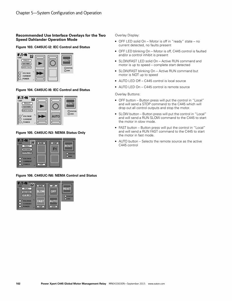
Chapter 5—System Configuration and Operation
Recommended Use Interface Overlays for the Two Speed Dahlander Operation Mode
Figure 103. C445UC-I2: IEC Control and Status
Figure 104. C445UC-I6: IEC Control and Status
Figure 105. C445UC-N3: NEMA Status Only
Figure 106. C445UC-N6: NEMA Control and Status
Overlay Display:
● OFF LED solid On – Motor is off in “ready” state – no current detected, no faults present
● OFF LED blinking On – Motor is off, C445 control is faulted and/or a control inhibit is present
● SLOW/FAST LED solid On – Active RUN command and motor is up to speed – complete start detected
● SLOW/FAST blinking On – Active RUN command but motor is NOT up to speed
● AUTO LED Off – C445 control is local source
● AUTO LED On – C445 control is remote source
Overlay Buttons:
● OFF button – Button press will put the control in “Local” and will send a STOP command to the C445 which will drop out all control outputs and stop the motor.
● SLOW button – Button press will put the control in “Local” and will send a RUN SLOW command to the C445 to start the motor in slow mode.
● FAST button – Button press will put the control in “Local” and will send a RUN FAST command to the C445 to start the motor in fast mode.
● AUTO button – Selects the remote source as the active C445 control
102 Power Xpert C445 Global Motor Management Relay MN042003EN—September 2015 www.eaton.com
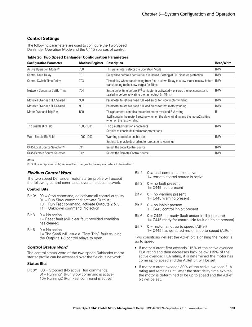
Chapter 5—System Configuration and Operation
Control Settings
The following parameters are used to configure the Two Speed Dahlander Operation Mode and the C445 sources of control.
Table 20. Two Speed Dahlander Configuration Parameters
Note1 Soft reset (power cycle) required for changes to these parameters to take effect.
Fieldbus Control WordThe two speed Dahlander motor starter profile will accept the following control commands over a fieldbus network.
Control Bits
Bit 0/1 00 = Stop command, de-activate all control outputs01 = Run Slow command, activate Output 110 = Run Fast command, activate Outputs 2 & 311 = Unknown command, No action
Bit 3 0 = No action1= Reset fault (will clear fault provided condition has cleared)
Bit 5 0 = No action1= The C445 will issue a “Test Trip” fault causing the Outputs 1-3 control relays to open.
Control Status WordThe control status word of the two speed Dahlander motor starter profile can be accessed over the fieldbus network.
Status Bits
Bit 0/1 00 = Stopped (No active Run commands)01= Running1 (Run Slow command is active)10= Running2 (Run Fast command is active)
Bit 2 0 = local control source active1= remote control source is active
Bit 3 0 = no fault present1= C445 fault present
Bit 4 0 = no warning present1= C445 warning present
Bit 5 0 = no inhibit present1= C445 control inhibit present
Bit 6 0 = C445 not ready (fault and/or inhibit present)1= C445 ready for control (No fault or inhibit present)
Bit 7 0 = motor is not up to speed (AtRef)1= C445 has detected motor is up to speed (AtRef)
Two conditions will set the AtRef bit, signaling the motor is up to speed.
● If motor current first exceeds 115% of the active overload FLA rating and then decreases back below 115% of the active overload FLA rating, it is determined the motor has come up to speed and the AtRef bit will be set.
● If motor current exceeds 30% of the active overload FLA rating and remains until after the start delay time expires the motor is determined to be up to speed and the AtRef bit will be set.
Configuration Parameter Modbus Register Description Read/Write
Active Operation Mode 1 700 This parameter selects the Operation Mode R/W
Control Fault Delay 701 Delay time before a control fault is issued. Setting of “0” disables protection. R/W
Control Switch Time Delay 703 Time delay when transitioning from fast -> slow. Delay to allow motor to slow before transitioning to the slow output (in 10ms)
R/W
Network Contactor Settle Time 704 Settle delay time before 2nd contactor is activated – ensures the net contactor is sealed in before activating the fast output (in 10ms)
R/W
Motor#1 Overload FLA Scaled 900 Parameter to set overload full load amps for slow motor winding R/W
Motor#2 Overload FLA Scaled 901 Parameter to set overload full load amps for fast motor winding R/W
Motor Overload Trip FLA 500 This parameter contains the active motor overload FLA rating (will contain the motor1 setting when on the slow winding and the motor2 setting when on the fast winding)
R
Trip Enable Bit Field 1000-1001 Trip (Fault) protection enable bitsSet bits to enable desired motor protections
R/W
Warn Enable Bit Field 1002-1003 Warning protection enable bitsSet bits to enable desired motor protections warnings
R/W
C445 Local Source Selector 1 711 Select the Local Control source. R/W
C445 Remote Source Selector 712 Select the Remote Control source. R/W
Power Xpert C445 Global Motor Management Relay MN042003EN—September 2015 www.eaton.com 103

Chapter 5—System Configuration and Operation
Wiring Diagrams for the Two Speed Dahlander Operation Mode
Figure 107. Isolated 24 Vdc Inputs/24 Vdc Outputs/24 Vdc Power
Figure 108. Non-isolated 24 Vdc Inputs/24 Vdc Outputs/24 Vdc C445 Power
RE
SE
T
RE
MO
TE
SLO
W
FAS
T
CH1T1 T2
V1 V2 V3
C445M...
L2
L3
PE
L1
F1
Q1
MOTOR3~
Q11FAST
Q12SLOW
PTC
Q13NET
6
54
1
23
I1 I2
C445BD-SD...
CH1CH2
CH1
C445UC...
I3 I4 C 0V 24V Q1 Q1 Q2 Q2 Q3 C Q3 24V 0V PE
C D0 D1
CH2
1 2 3 4 5 6 7 8
(+) Us
(-) Us24 VDC
Optional Modbus
Q12 Q11
Q13 Q12
Q13
(+) Uc
(-) Uc24 VDC
RE
SE
T
RE
MO
TE
SLO
W
FAS
T
CH1T1 T2
V1 V2 V3
C445M...
L2
L3
PE
L1
F1
Q1
I1 I2
C445BD-SD...
CH1CH2
CH1
C445UC...
I3 I4 C 0V 24V Q1 Q1 Q2 Q2 Q3 C Q3 24V 0V PE
C D0 D1
CH2
1 2 3 4 5 6 7 8
Optional Modbus
MOTOR3~
Q11FAST
Q12SLOW
PTC
Q13NET
6
54
1
23
Q12 Q11
Q13 Q12
Q13
(+) Us
(-) Us24 VDC
104 Power Xpert C445 Global Motor Management Relay MN042003EN—September 2015 www.eaton.com
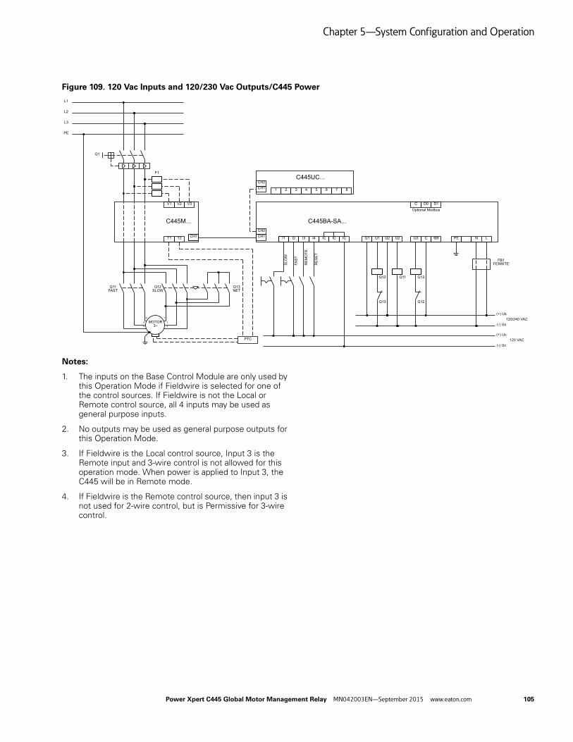
Chapter 5—System Configuration and Operation
Figure 109. 120 Vac Inputs and 120/230 Vac Outputs/C445 Power
Notes:
1. The inputs on the Base Control Module are only used by this Operation Mode if Fieldwire is selected for one of the control sources. If Fieldwire is not the Local or Remote control source, all 4 inputs may be used as general purpose inputs.
2. No outputs may be used as general purpose outputs for this Operation Mode.
3. If Fieldwire is the Local control source, Input 3 is the Remote input and 3-wire control is not allowed for this operation mode. When power is applied to Input 3, the C445 will be in Remote mode.
4. If Fieldwire is the Remote control source, then input 3 is not used for 2-wire control, but is Permissive for 3-wire control.
RE
SE
T
RE
MO
TE
SLO
W
FAS
T
CH1T1 T2
V1 V2 V3
C445M...
L2
L3
PE
L1
F1
Q1
I1 I2
C445BA-SA...
CH1CH2
CH1
C445UC...
I3 I4 IC IC IC
CH2
1 2 3 4 5 6 7 8
Q1 Q1 Q2 Q2 Q3 C Q3
C D0 D1
Optional Modbus
PE N L
(+) Us
(-) Us120/240 VAC
(+) Uc
(-) Uc120 VAC
FB1FERRITE
MOTOR3~
Q11FAST
Q12SLOW
PTC
Q13NET
6
54
1
13
Q12 Q11
Q13 Q12
Q13
Power Xpert C445 Global Motor Management Relay MN042003EN—September 2015 www.eaton.com 105

Chapter 5—System Configuration and Operation
Auto Transformer Operation Mode
The auto transformer reduced voltage motor starter profile accepts start/stop commands to control motors wired in a reduced voltage auto transformer configuration. When a start command is received Output 3(star) will be activated. Then after the Network Contactor Delay time expires, Output 1(start) activates starting the motor with the reduced voltage from the auto transformer. When the C445 detects the motor is up to speed or the Maximum Star Winding Time expires, whichever occurs first, the Network Contactor Delay timer is started and Output 3 is de-activated. After the Network Contactor Delay time expires, Output 2(run) also activates, which transitions the transformer to full voltage. After a second Network Contactor Delay time expires, Output 1(start) de-activates placing the control into full voltage run mode.
The C445 will issue a control fault when:
● A Run1 command is active and phase voltage is present and no phase current is detected after the Control Switching Time expires.
● A Stop command is active and current is detected after the Control Switching Time expires.
Outputs 1, 2 and 3 will be de-activated anytime the C445 experiences a fault/inhibit condition.
● Output 1 – auto transformer reduced voltage starter START coil (NO)
● Output 2 – auto transformer reduced voltage starter RUN coil (NO)
● Output 3 – auto transformer reduced voltage starter STAR coil (NO)
Figure 110. Timing Diagram for the Auto Transformer Operation Mode
Recommended User Interface Overlays for the Auto Transformer Operation Mode
Figure 111. C445UC-I0: IEC Control and Status
Figure 112. C445UC-I1: IEC Status Only
Figure 113. C445UC-I4: IEC Control and Status
Figure 114. C445UC-N0: NEMA Control and Status
STAR
START
Timing Diagram
RUN
Settle Time
Max star time
Settle Time
Control Fault Delay
Control Fault Delay
106 Power Xpert C445 Global Motor Management Relay MN042003EN—September 2015 www.eaton.com

Chapter 5—System Configuration and Operation
Figure 115. C445UC-N1: NEMA Status Only
Figure 116. C445UC-N4: NEMA Control and Status
Overlay Display:
● OFF LED solid On – Motor is off in “ready” state – no current detected, no faults present
● OFF LED blinking On – Motor is off, C445 control is faulted and/or a control inhibit is present
● RUN LED solid On – Active RUN1 command and motor is up to speed – complete start detected
● RUN LED blinking On – Active RUN1 command but motor is NOT up to speed
● AUTO LED Off – C445 control is local source
● AUTO LED On – C445 control is remote source
Overlay Buttons:
● OFF button – Button press will put the control in “Local” and will send a STOP command to the C445 overload to drop out the starter.
● RUN button – Button press will put the control in “Local” and will send a RUN1 command to the C445 overload to start the starter.
● AUTO button – Selects the remote source as the active C445 control
● RESET button – Resets fault if condition has cleared
● HAND button – Button press will put the control in “Local” and will send a RUN1 command to the C445 overload to start the starter.
Power Xpert C445 Global Motor Management Relay MN042003EN—September 2015 www.eaton.com 107

Chapter 5—System Configuration and Operation
Control Settings
The following parameters are used to configure the auto transformer reduced voltage motor starter control profile and the C445 sources of control.
Table 21. Auto Transformer Configuration Parameters
Fieldbus Control WordThe auto transformer reduced voltage motor starter profile will accept the following control commands over a fieldbus network.
Control Bits
Bit 0 0 = Stop command, de-activate all control outputs1 = Run1 command, begin start sequence
Bit 3 0 = No action1= Reset fault (will clear fault provided condition has cleared)
Bit 5 0 = No action1= The C445 will issue a “Test Trip” fault causing the Outputs 1-3 control relays to open
Control Status WordThe control status word of the auto transformer reduced voltage motor starter profile can be accessed over the fieldbus network.
Status Bits
Bit 0 0 = Stopped (No active Run1 command)1= Running1 (Run1 command is present)
Bit 2 0 = local control source active1= remote control source is active
Bit 3 0 = no fault present1= C445 fault present
Bit 4 0 = no warning present1= C445 warning present
Bit 5 0 = no inhibit present1= C445 control inhibit present
Bit 6 0 = C445 not ready (fault and/or inhibit present)1= C445 ready for control (No fault or inhibit present)
Bit 7 0 = motor is not up to speed (AtRef)1= C445 has detected motor is up to speed on delta winding (AtRef)
Two conditions will set the AtRef bit, signaling the motor is up to speed.
● After transitioning to the full voltage output, if motor current increases above 115% of the active overload FLA rating and then decreases back below 115% of the active overload FLA rating, it is determined the motor has come up to speed and the AtRef bit will be set.
● After transitioning to the full voltage output, if motor current exceeds 30% of the active overload FLA rating and remains until after the start delay time expires the motor is determined to be up to speed and the AtRef bit will be set.
Configuration Parameter Modbus Register Description Read/Write
*C445 Active Operation Mode 700 Parameter selects control profile; Set to “6” for auto transformer reduced voltage motor starter
R/W
Control Fault Delay 701 Delay time from change in command before a control fault is issued. Setting of “0” disables this protection.
R/W
Network Contactor Settle Time 704 Settle delay time before second contactor is activated – ensures the first contactor is sealed in before applying the line (in 10 ms)
R/W
Maximum Star Winding Time 705 Maximum time the control will stay on the reduced voltage output before transitioning to full voltage (in 100 ms)
R/W
Motor#1 Overload FLA Scaled 900 Parameter to set motor nameplate full load amp rating for overload and motor protections
R/W
Motor#2 Overload FLA Scaled 901 Not used R/W
Motor Overload Trip FLA 500 Parameter holds active motor overload FLA rating (will contain the motor1 setting) R
Trip Enable Bit Field 1000-1001 Trip (Fault) protection enable bitsSet bits to enable desired motor protections
R/W
Warn Enable Bit Field 1002-1003 Warning protection enable bitsSet bits to enable desired motor protections warnings
R/W
*C445 Local Source Selector 711 See Section – C445 Local/Remote Control Source Selection R/W
C445 Remote Source Selector 712 See Section – C445 Local/Remote Control Source Selection R/W
108 Power Xpert C445 Global Motor Management Relay MN042003EN—September 2015 www.eaton.com

Chapter 5—System Configuration and Operation
Wiring Diagrams for the Auto Transformer Operation Mode
Figure 117. Isolated 24 Vdc Inputs/24 Vdc Outputs/24 Vdc Power
Figure 118. Non-isolated 24 Vdc Inputs/24 Vdc Outputs/24 Vdc C445 Power
RE
SE
T
RE
MO
TE
RU
N
CH1T1 T2
V1 V2 V3
C445M...
I1 I2
C445BD-SD...
CH1CH2
CH1
C445UC...
I3 I4 C 0V 24V Q1 Q1 Q2 Q2 Q3 C Q3 24V 0V PE
C D0 D1
CH2
1 2 3 4 5 6 7 8
L2
L3
PE
L1
Optional Modbus
F1
Q1
Q11START
Q12RUN
Q13STAR
PTCMOTOR3~
(+) Uc
(-) Uc24 VDC
(+) Us
(-) Us24 VDC
Q11 Q12
Q13 Q12
Q13
T1
RE
SE
T
RE
MO
TE
RU
N
CH1T1 T2
V1 V2 V3
C445M...
I1 I2CH1CH2
CH1
I3 I4 C 0V 24V Q1 Q1 Q2 Q2 Q3 C Q3 24V 0V PE
C D0 D1
CH2
1 2 3 4 5 6 7 8
L2
L3
PE
L1
Optional Modbus
F1
Q1
C445BD-SD...
C445UC...
Q11START
Q12RUN
Q13STAR
PTCMOTOR3~
Q11 Q12
Q13 Q12
Q13
(+) Us
(-) Us24 VDC
T1
Power Xpert C445 Global Motor Management Relay MN042003EN—September 2015 www.eaton.com 109

Chapter 5—System Configuration and Operation
Figure 119. 120 Vac Inputs and 120/230 Vac Outputs/C445 Power
Notes:
1. The inputs on the Base Control Module are only used by this Operation Mode if Fieldwire is selected for one of the control sources. If Fieldwire is not the Local or Remote control source, all 4 inputs may be used as general purpose inputs.
2. No outputs may be used as general purpose outputs for this Operation Mode.
3. If Fieldwire is the Local control source, Input 3 is the Remote input. When power is applied to Input 3, the C445 will be in Remote mode.
4. If Fieldwire is the Remote control source and 2-wire control (default) is selected, Input 3 is unused by this operation mode.
5. If 3-wire control is selected along with Fieldwire for either control source, Input 2 is Permissive.
RE
SE
T
RE
MO
TE
RU
N
CH1T1 T2
V1 V2 V3
C445M...
I1 I2
C445BA-SA...
CH1CH2
CH1
C445UC...
I3 I4 IC Q1 Q1 Q2 Q2 Q3 C Q3
C D0 D1
CH2
1 2 3 4 5 6 7 8
L2
L3
PE
L1
Optional Modbus
F1
Q1
PE N LIC IC
(+) Us
(-) Us120/240 VAC
(+) Uc
(-) Uc120 VAC
FB1FERRITE
Q11START
Q12RUN
Q13STAR
PTCMOTOR3~
Q11 Q12
Q13 Q12
Q13
T1
110 Power Xpert C445 Global Motor Management Relay MN042003EN—September 2015 www.eaton.com

Chapter 5—System Configuration and Operation
Solenoid Valve Operation Mode
The Solenoid Valve operation mode accepts energize/de-energize commands to open/close a solenoid controlled valve. The control can be adapted to both normally open & normally closed valves. An energize command will activate the Output 1. A de-energize command will de-activate Output 1. Limit switches can be used to provide feedback to the C445 indicating when the valve reaches open/closed positions.
Solenoid parameters:
● Solenoid Non-energized state
● Solenoid Open Delay
● Solenoid Close Delay
C445 Feedback Signal Source Selector parameter.
Input source of the feedback signals:
● 0 – No feedback source
● 1 – User interface inputs (In#2 – open_fb, In#3 – close_fb)
● 2 – Base control inputs (In#2 – open_fb, In#3 – close_fb)
● 3 – Fieldbus parameter (2nd bit – open_fb, 3rd bit – close_fb)
The C445 will issue a control fault when:
● Both closed and open feedback is detected
Normally closed valve
● An Energize command is active and no open feedback is detected
● A De-energize command is active and no closed feedback is detected
Normally open valve
● An Energize command is active and no closed feedback is detected
● A De-energize command is active and no open feedback is detected
Output 1 will be de-activated when the C445 experiences a fault/inhibit condition.
Output 1 – solenoid coil (NO)
Output 2 – open for user configuration and their function can be selected by the user.
Output 3 – open for user configuration and their function can be selected by the user.
Figure 120. Timing Diagram for the Solenoid Valve Operation Mode
Recommended User Interface Overlays for the Solenoid Valve Operation Mode
Figure 121. C445UC-I0: IEC Control and Status
Figure 122. C445UC-I4: IEC Control and Status
ENERGIZE
*Control Fault delay
Timing Diagram
DE-ENERGIZE
*Normal state = Closed De-energize to energize transition (open delay active)Energize to de-energize transition (close delay active)
*Normal state = Open De-energize to energize transition (close delay active)Energize to de-energize transition (open delay active)
Power Xpert C445 Global Motor Management Relay MN042003EN—September 2015 www.eaton.com 111

Chapter 5—System Configuration and Operation
Figure 123. C445UC-N0: NEMA Control and Status
Figure 124. C445UC-N4: NEMA Control and Status
Overlay Display:
● OFF LED solid On – Solenoid in non-energized state; no faults/inhibits present, “Ready”
● OFF LED blinking On – Solenoid in non-energized state; faults/inhibits is present, “Not Ready”
● RUN LED solid On – Energize command is active - Not in position (feedback open)
● RUN LED blinking On – Energize command is active - In position (feedback closed)
● AUTO LED Off – C445 control is local source
● AUTO LED On – C445 control is remote source
Overlay Buttons:
● OFF button – Button press will put the control in “Local” and will send a STOP command to the C445 overload to de-energize the solenoid
● RUN button – Button press will put the control in “Local” and will send a RUN1 command to the C445 overload to energize the solenoid
● AUTO button – Selects the remote source as the active C445 control
● RESET button – Resets fault if condition has cleared
● HAND button – Button press will put the control in “Local” and will send a RUN1 command to the C445 overload to energize the solenoid
112 Power Xpert C445 Global Motor Management Relay MN042003EN—September 2015 www.eaton.com
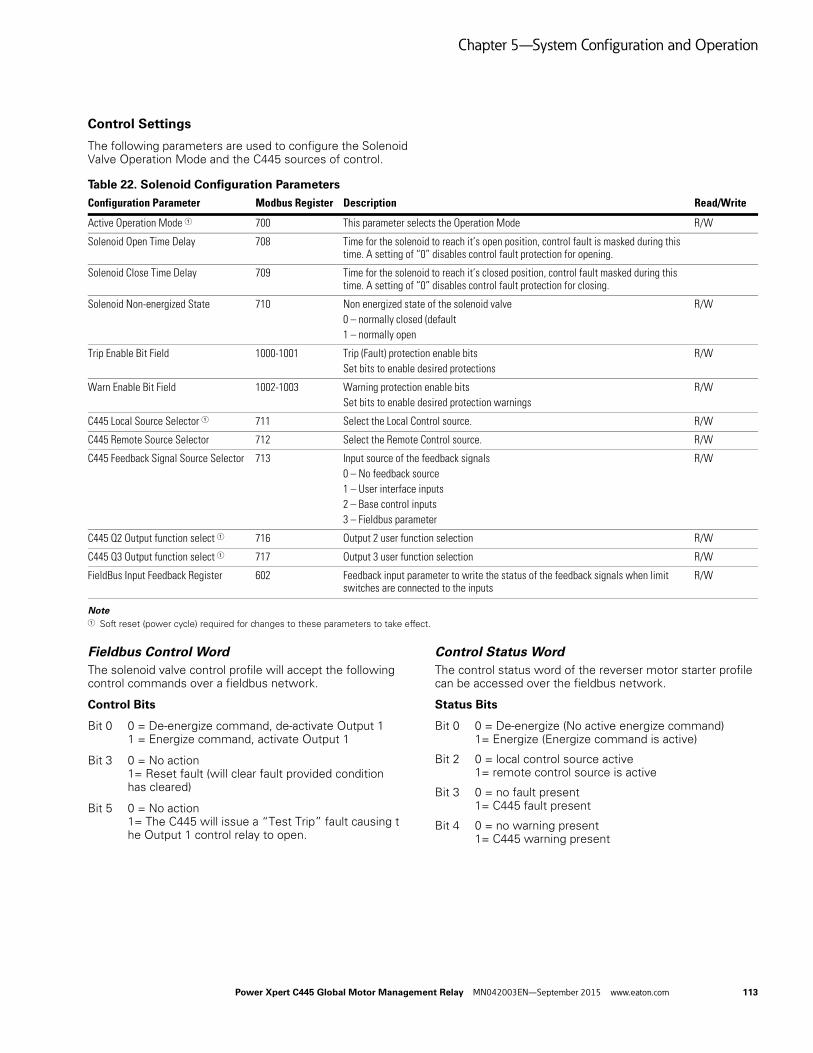
Chapter 5—System Configuration and Operation
Control Settings
The following parameters are used to configure the Solenoid Valve Operation Mode and the C445 sources of control.
Table 22. Solenoid Configuration Parameters
Note1 Soft reset (power cycle) required for changes to these parameters to take effect.
Fieldbus Control WordThe solenoid valve control profile will accept the following control commands over a fieldbus network.
Control Bits
Bit 0 0 = De-energize command, de-activate Output 11 = Energize command, activate Output 1
Bit 3 0 = No action1= Reset fault (will clear fault provided condition has cleared)
Bit 5 0 = No action1= The C445 will issue a “Test Trip” fault causing the Output 1 control relay to open.
Control Status WordThe control status word of the reverser motor starter profile can be accessed over the fieldbus network.
Status Bits
Bit 0 0 = De-energize (No active energize command)1= Energize (Energize command is active)
Bit 2 0 = local control source active1= remote control source is active
Bit 3 0 = no fault present1= C445 fault present
Bit 4 0 = no warning present1= C445 warning present
Configuration Parameter Modbus Register Description Read/Write
Active Operation Mode 1 700 This parameter selects the Operation Mode R/W
Solenoid Open Time Delay 708 Time for the solenoid to reach it’s open position, control fault is masked during this time. A setting of “0” disables control fault protection for opening.
Solenoid Close Time Delay 709 Time for the solenoid to reach it’s closed position, control fault masked during this time. A setting of “0” disables control fault protection for closing.
Solenoid Non-energized State 710 Non energized state of the solenoid valve0 – normally closed (default1 – normally open
R/W
Trip Enable Bit Field 1000-1001 Trip (Fault) protection enable bitsSet bits to enable desired protections
R/W
Warn Enable Bit Field 1002-1003 Warning protection enable bitsSet bits to enable desired protection warnings
R/W
C445 Local Source Selector 1 711 Select the Local Control source. R/W
C445 Remote Source Selector 712 Select the Remote Control source. R/W
C445 Feedback Signal Source Selector 713 Input source of the feedback signals0 – No feedback source1 – User interface inputs2 – Base control inputs 3 – Fieldbus parameter
R/W
C445 Q2 Output function select 1 716 Output 2 user function selection R/W
C445 Q3 Output function select 1 717 Output 3 user function selection R/W
FieldBus Input Feedback Register 602 Feedback input parameter to write the status of the feedback signals when limit switches are connected to the inputs
R/W
Power Xpert C445 Global Motor Management Relay MN042003EN—September 2015 www.eaton.com 113

Chapter 5—System Configuration and Operation
Bit 5 0 = no inhibit present1= C445 control inhibit present
Bit 6 0 = C445 not ready (fault and/or inhibit present)1= C445 ready for control (No fault or inhibit present)
Bit 7 0 = valve is in not desired end position1= valve is in desired end position
The following conditions will set the InPos bit in the status word, signaling the valve has reached the desired end position.
Normally closed valve
● Energize command is active and open feedback detected
● De-energize command is active and Closed feedback detected
Normally open valve
● Energize command is active and closed feedback detected
● De-energize command is active and open feedback detected.
114 Power Xpert C445 Global Motor Management Relay MN042003EN—September 2015 www.eaton.com
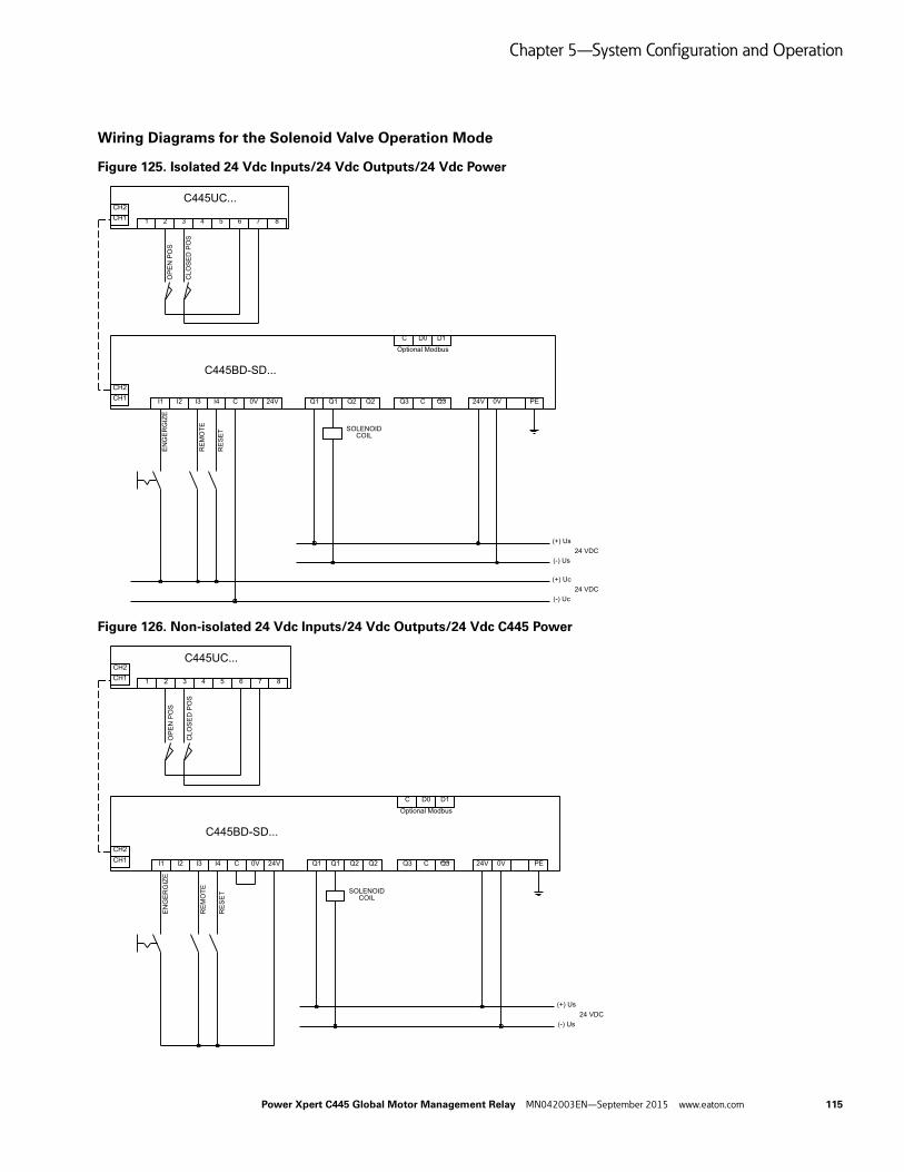
Chapter 5—System Configuration and Operation
Wiring Diagrams for the Solenoid Valve Operation Mode
Figure 125. Isolated 24 Vdc Inputs/24 Vdc Outputs/24 Vdc Power
Figure 126. Non-isolated 24 Vdc Inputs/24 Vdc Outputs/24 Vdc C445 Power
RE
SE
T
RE
MO
TE
EN
GE
RG
IZE
OP
EN
PO
S
CLO
SE
D P
OS
I1 I2
C445BD-SD...
CH1CH2
CH1
C445UC...
I3 I4 C 0V 24V Q1 Q1 Q2 Q2 Q3 C Q3 24V 0V PE
C D0 D1
CH2
1 2 3 4 5 6 7 8
Optional Modbus
SOLENOID COIL
(+) Uc
(-) Uc24 VDC
(+) Us
(-) Us24 VDC
RE
SE
T
RE
MO
TE
EN
GE
RG
IZE
OP
EN
PO
S
CLO
SE
D P
OS
I1 I2
C445BD-SD...
CH1CH2
CH1
C445UC...
I3 I4 C 0V 24V Q1 Q1 Q2 Q2 Q3 C Q3 24V 0V PE
C D0 D1
CH2
1 2 3 4 5 6 7 8
Optional Modbus
SOLENOID COIL
(+) Us
(-) Us24 VDC
Power Xpert C445 Global Motor Management Relay MN042003EN—September 2015 www.eaton.com 115
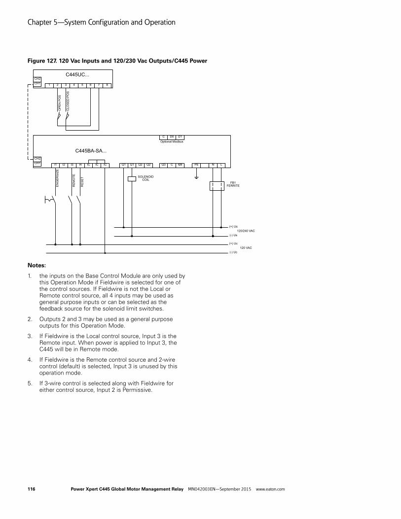
Chapter 5—System Configuration and Operation
Figure 127. 120 Vac Inputs and 120/230 Vac Outputs/C445 Power
Notes:
1. the inputs on the Base Control Module are only used by this Operation Mode if Fieldwire is selected for one of the control sources. If Fieldwire is not the Local or Remote control source, all 4 inputs may be used as general purpose inputs or can be selected as the feedback source for the solenoid limit switches.
2. Outputs 2 and 3 may be used as a general purpose outputs for this Operation Mode.
3. If Fieldwire is the Local control source, Input 3 is the Remote input. When power is applied to Input 3, the C445 will be in Remote mode.
4. If Fieldwire is the Remote control source and 2-wire control (default) is selected, Input 3 is unused by this operation mode.
5. If 3-wire control is selected along with Fieldwire for either control source, Input 2 is Permissive.
RE
SE
T
RE
MO
TE
EN
GE
RG
IZE
OP
EN
PO
S
CLO
SE
D P
OS
I1 I2
C445BA-SA...
CH1CH2
I3 I4 IC Q1 Q1 Q2 Q2 Q3 C Q3
C D0 D1
Optional Modbus
PE N LIC IC
(+) Us
(-) Us120/240 VAC
(+) Uc
(-) Uc120 VAC
FB1FERRITE
CH1
C445UC...CH2
1 2 3 4 5 6 7 8
SOLENOID COIL
116 Power Xpert C445 Global Motor Management Relay MN042003EN—September 2015 www.eaton.com

Chapter 5—System Configuration and Operation
MCCB Feeder Operation Mode
The MCCB feeder operation mode has two modes of operation with actuation and without actuation.
When MCCB actuation is enabled, it provides remote control capability for MCCB installed with motor operators. A close command will activate Output 1 for the programmed pulse width providing a close signal to the motor operator. An open command will activate Output 2 for the programmed pulse width providing an open signal to the motor operator.
MCCB parameters:
● MCCB Actuation Enable
● Actuation Pulse Width
CB On & CB Alarm auxiliary relays provide feedback, reporting MCCB feeder open, close, & trip status.
C445 Feedback Signal Source Selector parameter.
Input source of the feedback signals:
0 – No feedback source
1 – User interface inputs (In#2 – cb_on, In#3 – cb_alarm)
2 – Base control inputs (In#2 – cb_on, In#3 – cb_alarm)
3 – Fieldbus parameter (2nd bit – cb_on, 3rd bit – cb_alarm)
The C445 will issue a control fault when:
● An Open command is active and the CB On feedback input is true.
● The CB On & CB Alarm feedback inputs are both “high” at same time.
● Current is detected after an open command.
● A Close command is active and the CB On feedback input is false.
When the C445 experiences a fault/inhibit condition Output 2 will be activated for the programmed pulse width to open the breaker feeder.
● Output 1 – close control (NO)
● Output 2 – open control (NO)
● Output 3 – open for user configuration and their function can be selected by the user.
Figure 128. Timing Diagram for MCCB Feeder Operation Mode
CLOSE Command
Timing Diagram
Pulse Width
If CB ON aux = openIssue Control faultCLOSE
Output
OPEN Output
Pulse Width
Control Fault Delay
If CB ON aux = closedIssue Control fault
Control Fault Delay
Power Xpert C445 Global Motor Management Relay MN042003EN—September 2015 www.eaton.com 117

Chapter 5—System Configuration and Operation
Recommended User Interface Overlays for the MCCB Feeder Operation Mode
Figure 129. C445UC-I7: IEC Control and Status
Figure 130. C445UC-I8: IEC Control and Status
Figure 131. C445UC-N7: NEMA Control and Status
Figure 132. C445UC-N8: NEMA Control and Status
Overlay Display:
● OFF LED solid On – Feeder is in “Off” or “Tripped” position; CB ON aux input is low.
● RUN LED blinking On – Feeder has an active “Close” command but is in open position; CB ON aux input is low.
● RUN LED solid On – Feeder is in “On” position; CB ON aux input is high.
● AUTO LED Off – C445 control is local source
● AUTO LED On – C445 control is remote source
● FAULT LED solid On – C445 controller is faulted.
● WARNING LED solid On – C445 controller has an active warning present.
● TRIPPED LED solid On – Feeder is in the “Tripped” state CB ALARM aux input is high
Overlay Buttons:
● OFF button – Button press will put the control in “Local” and will send an OPEN command to the C445 to open the feeder.
● CLOSE button – Button press will put the control in “Local” and will send an CLOSE command to the C445 to close the feeder.
● AUTO button – Selects the remote source as the active C445 control
● RESET button – Resets fault if condition has cleared
118 Power Xpert C445 Global Motor Management Relay MN042003EN—September 2015 www.eaton.com

Chapter 5—System Configuration and Operation
Control Settings
The following parameters are used to configure the MCCB Feeder Operation Mode and the C445 sources of control.
Table 23. MCCB Configuration Parameters
Note1 Soft reset (power cycle) required for changes to these parameters to take effect.
Fieldbus Control WordThe MCCB feeder control profile will accept the following control commands over a fieldbus network.
Control Bits
Bit 0/1 0 = Open command, activate Output 2 for pulse width1 = Close command, activate Output 1 for pulse width
Bit 3 0 = No action1= Reset fault (will clear fault provided condition has cleared)
Bit 5 0 = No action1 = The C445 will issue a “Test Trip” fault causing the Output 2 control relay to produce an output pulseto open the MCCB feeder.
Control Status WordThe control status word of the MCCB feeder control profile can be accessed over the fieldbus network.
Status Bits
Bit 0 0 = Open (open command is active1= Close (close command is active)
Bit 1 0 = circuit breaker not in tripped position (CB alarm = false)1= circuit breaker in tripped position (CB alarm = true)
Bit 2 0 = local control source active1= remote control source is active
Bit 3 0 = no fault present1= C445 fault present
Bit 4 0 = no warning present1= C445 warning present
Bit 5 0 = no inhibit present1= C445 control inhibit present
Bit 6 0 = C445 not ready (fault and/or inhibit present)1= C445 ready for control (No fault or inhibit present)
Bit 7 0 = MCCB feeder is in open/tripped position (CB on = false)1= MCCB feeder is in closed position (CB on = true)
Configuration Parameter Modbus Register Description Read/Write
Active Operation Mode 1 700 This parameter selects the Operation Mode R/W
Control Fault Delay 701 Delay time before a control fault is issued. Setting of “0” disables protection. R/W
MCCB Actuation Enable 705 Enable/disables the actuation control for the MCCB feeder control profile R/W
Actuation Pulse Width 706 Minimum required motor operator control signal pulse width (in 1ms) R/W
Motor#1 Overload FLA Scaled 900 Parameter can be used to set load limits R/W
Motor Overload Trip FLA 500 Parameter holds the active load rating R
Trip Enable Bit Field 1000-1001 Trip (Fault) protection enable bitsSet bits to enable desired protections
R/W
Warn Enable Bit Field 1002-1003 Warning protection enable bitsSet bits to enable desired protections warnings
R/W
C445 Local Source Selector 1 711 Select the Local Control source. R/W
C445 Remote Source Selector 712 Select the Remote Control source. R/W
C445 Feedback Signal Source Selector 713 Input source of the feedback signals0 – No feedback source1 – User interface inputs 2 – Base control inputs 3 – Fieldbus parameter
R/W
C445 Q3 Output function select 1 717 Output 3 user function selection R/W
FieldBus Input Feedback Register 602 Feedback input parameter to write the status of the feedback signals when MCCB aux switches are connected to the inputs
R/W
Power Xpert C445 Global Motor Management Relay MN042003EN—September 2015 www.eaton.com 119
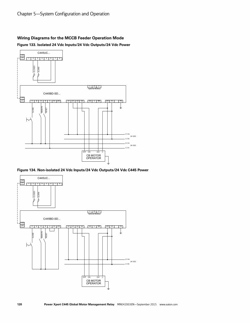
Chapter 5—System Configuration and Operation
Wiring Diagrams for the MCCB Feeder Operation Mode
Figure 133. Isolated 24 Vdc Inputs/24 Vdc Outputs/24 Vdc Power
Figure 134. Non-isolated 24 Vdc Inputs/24 Vdc Outputs/24 Vdc C445 Power
CLO
SE
D
ALA
RM
CLO
SE
I1 I2
C445BD-SD...
CH1CH2
I3 I4 C 0V 24V Q1 Q1 Q2 Q2 Q3 C Q3 24V 0V PE
C D0 D1
Optional Modbus
RE
SE
T
RE
MO
TE
CB MOTOR OPERATOR
24V CONOFF
CH1
C445UC...CH2
1 2 3 4 5 6 7 8
(+) Uc
(-) Uc24 VDC
(+) Us
(-) Us24 VDC
CLO
SE
D
ALA
RM
CLO
SE
I1 I2
C445BD-SD...
CH1CH2
I3 I4 C 0V 24V Q1 Q1 Q2 Q2 Q3 C Q3 24V 0V PE
C D0 D1
Optional Modbus
CB MOTOR OPERATOR
24V CONOFF
CH1
C445UC...CH2
1 2 3 4 5 6 7 8
(+) Us
(-) Us24 VDC
RE
SE
T
RE
MO
TE
120 Power Xpert C445 Global Motor Management Relay MN042003EN—September 2015 www.eaton.com

Chapter 5—System Configuration and Operation
Figure 135. 120 Vac Inputs and 120/230 Vac Outputs/C445 Power
Notes:
1. The inputs on the Base Control Module are only used by this Operation Mode if Fieldwire is selected for one of the control sources. If Fieldwire is not the Local or Remote control source, all 4 inputs may be used as general purpose inputs or can be selected as the feedback source for the CB aux contacts.
2. Output 3 may be used as general purpose output for this Operation Mode.
3. If Fieldwire is the Local control source, Input 3 is the Remote input. When power is applied to Input 3, the C445 will be in Remote mode.
4. If Fieldwire is the Remote control source and 2-wire control (default) is selected, Input 3 is unused by this operation mode.
CLO
SE
D
ALA
RM
CLO
SE
I1 I2CH1CH2
I3 I4 Q1 Q1 Q2 Q2 Q3 C Q3
C D0 D1
Optional Modbus
CB MOTOR OPERATOR
24V CONOFF
CH1
C445UC...CH2
1 2 3 4 5 6 7 8
(+) Us
(-) Us24 VDC
(+) Us
(-) Us120/240VAC
PE N L
FB1FERRITE
IC IC IC
RE
SE
T
RE
MO
TE
C445BA-SA...
Power Xpert C445 Global Motor Management Relay MN042003EN—September 2015 www.eaton.com 121

Chapter 5—System Configuration and Operation
Contactor Feeder Operation Mode
The Contactor Feeder operation mode accepts open/close commands to control the contactor in a feeder application.
A close command will activate Output 1. An open command will de-activate Output 1.
C445 Feedback Signal Source Selector parameter.Input source of the feedback signals:
● 0 – No feedback source
● 1 – User interface inputs (In#2 – aux on)
● 2 – Base control inputs (In#2 – aux on)
● 3 – Fieldbus parameter (2nd bit – aux on)
The C445 will issue a control fault when:
● An Open command active and the Aux On feedback input is true.
● Current is detected after an open command.
● A Close command is active and the Aux On feedback input is false.
When the C445 experiences a fault/inhibit condition Output 1 will be de-activated to open the feeder.
● Output 1 – feeder contactor coil (NO)
● Outputs 2 and 3 – open for user configuration and their function can be selected by the user.
Figure 136. Timing Diagram for the Contactor Feeder Operating Mode
Recommended User Interface Overlays for the Contactor Feeder Operating Mode
Figure 137. C445UC-I7: IEC Control and Status
Figure 138. C445UC-I8: IEC Control and Status
Figure 139. C445UC-N7: NEMA Control and Status
Figure 140. C445UC-N8: NEMA Control and StatusCLOSE
Control Fault delay
Timing Diagram
OPEN
122 Power Xpert C445 Global Motor Management Relay MN042003EN—September 2015 www.eaton.com

Chapter 5—System Configuration and Operation
Overlay Display:
● OFF LED solid On – Feeder is in “Off” or “Tripped” position; CB ON aux input is low.
● RUN LED blinking On – Feeder has an active “Close” command but is in open position; CB ON aux input is low.
● RUN LED solid On – Feeder is in “On” position; CB ON aux input is high.
● AUTO LED Off – C445 control is local source
● AUTO LED On – C445 control is remote source
● FAULT LED solid On – C445 controller is faulted.
● WARNING LED solid On – C445 controller has an active warning present.
● TRIPPED LED solid On – Feeder is in the “Tripped” state CB ALARM aux input is high
Overlay Buttons:
● OFF button – Button press will put the control in “Local” and will send an OPEN command to the C445 to open the feeder.
● CLOSE button – Button press will put the control in “Local” and will send an CLOSE command to the C445 to close the feeder.
● AUTO button – Selects the remote source as the active C445 control
● RESET button – Resets fault if condition has cleared
Power Xpert C445 Global Motor Management Relay MN042003EN—September 2015 www.eaton.com 123
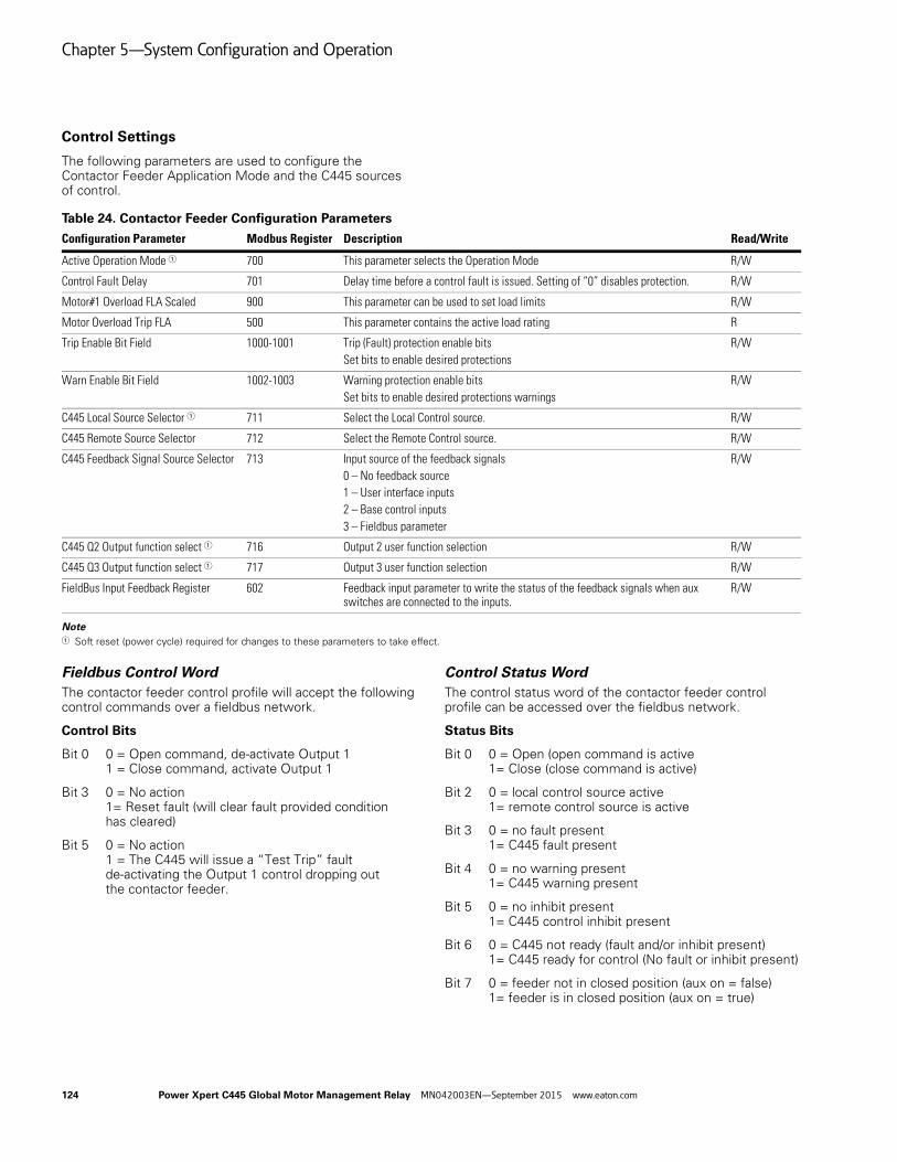
Chapter 5—System Configuration and Operation
Control Settings
The following parameters are used to configure the Contactor Feeder Application Mode and the C445 sources of control.
Table 24. Contactor Feeder Configuration Parameters
Note1 Soft reset (power cycle) required for changes to these parameters to take effect.
Fieldbus Control WordThe contactor feeder control profile will accept the following control commands over a fieldbus network.
Control Bits
Bit 0 0 = Open command, de-activate Output 11 = Close command, activate Output 1
Bit 3 0 = No action1= Reset fault (will clear fault provided condition has cleared)
Bit 5 0 = No action1 = The C445 will issue a “Test Trip” fault de-activating the Output 1 control dropping out the contactor feeder.
Control Status WordThe control status word of the contactor feeder control profile can be accessed over the fieldbus network.
Status Bits
Bit 0 0 = Open (open command is active1= Close (close command is active)
Bit 2 0 = local control source active1= remote control source is active
Bit 3 0 = no fault present1= C445 fault present
Bit 4 0 = no warning present1= C445 warning present
Bit 5 0 = no inhibit present1= C445 control inhibit present
Bit 6 0 = C445 not ready (fault and/or inhibit present)1= C445 ready for control (No fault or inhibit present)
Bit 7 0 = feeder not in closed position (aux on = false)1= feeder is in closed position (aux on = true)
Configuration Parameter Modbus Register Description Read/Write
Active Operation Mode 1 700 This parameter selects the Operation Mode R/W
Control Fault Delay 701 Delay time before a control fault is issued. Setting of “0” disables protection. R/W
Motor#1 Overload FLA Scaled 900 This parameter can be used to set load limits R/W
Motor Overload Trip FLA 500 This parameter contains the active load rating R
Trip Enable Bit Field 1000-1001 Trip (Fault) protection enable bitsSet bits to enable desired protections
R/W
Warn Enable Bit Field 1002-1003 Warning protection enable bitsSet bits to enable desired protections warnings
R/W
C445 Local Source Selector 1 711 Select the Local Control source. R/W
C445 Remote Source Selector 712 Select the Remote Control source. R/W
C445 Feedback Signal Source Selector 713 Input source of the feedback signals0 – No feedback source1 – User interface inputs 2 – Base control inputs 3 – Fieldbus parameter
R/W
C445 Q2 Output function select 1 716 Output 2 user function selection R/W
C445 Q3 Output function select 1 717 Output 3 user function selection R/W
FieldBus Input Feedback Register 602 Feedback input parameter to write the status of the feedback signals when aux switches are connected to the inputs.
R/W
124 Power Xpert C445 Global Motor Management Relay MN042003EN—September 2015 www.eaton.com
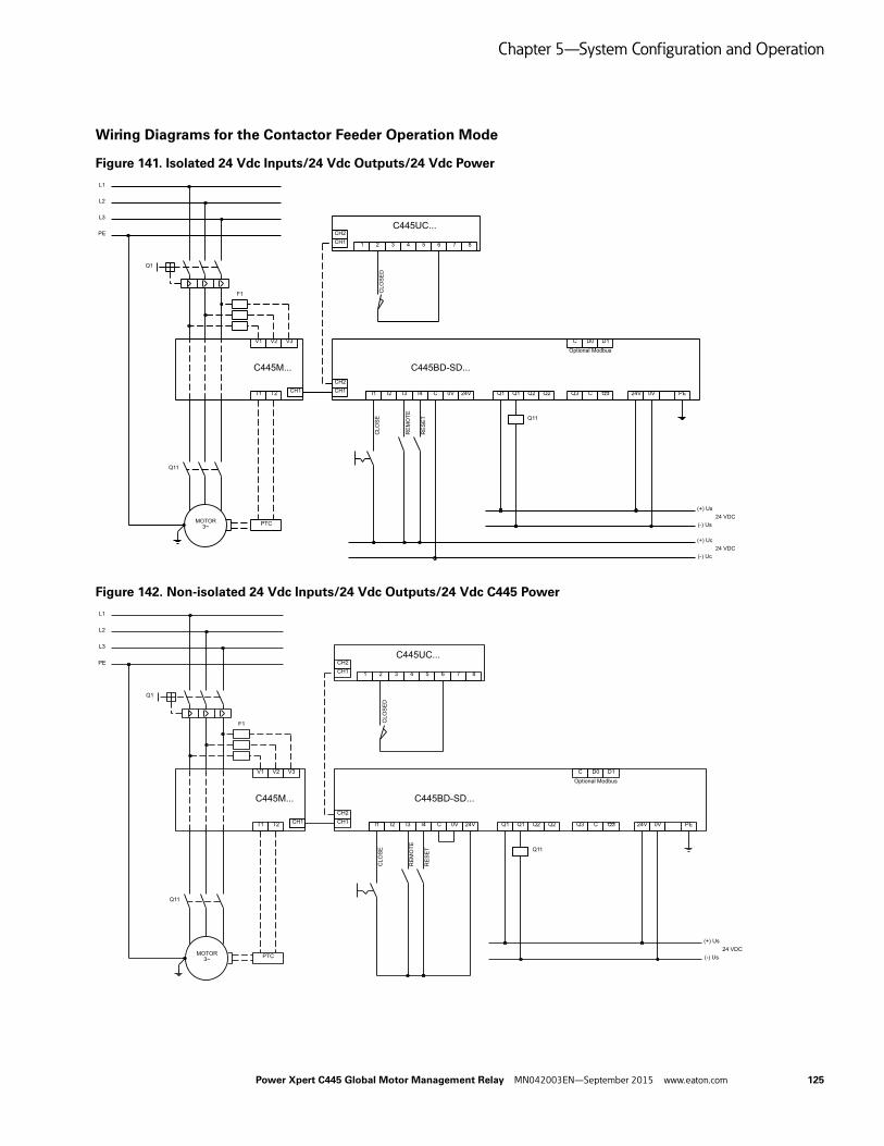
Chapter 5—System Configuration and Operation
Wiring Diagrams for the Contactor Feeder Operation Mode
Figure 141. Isolated 24 Vdc Inputs/24 Vdc Outputs/24 Vdc Power
Figure 142. Non-isolated 24 Vdc Inputs/24 Vdc Outputs/24 Vdc C445 Power
CLO
SE
DC
LOS
E
CH1T1 T2
V1 V2 V3
C445M...
I1 I2
C445BD-SD...
CH1CH2
I3 I4 C 0V 24V Q1 Q1 Q2 Q2 Q3 C Q3 24V 0V PE
C D0 D1
PTCMOTOR3~
L2
L3
PE
L1
Optional Modbus
F1
Q11
Q1
Q11R
ES
ET
RE
MO
TE
CH1
C445UC...CH2
1 2 3 4 5 6 7 8
(+) Uc
(-) Uc24 VDC
(+) Us
(-) Us24 VDC
CLO
SE
DC
LOS
E
L2
L3
PE
L1
CH1T1 T2
V1 V2 V3
C445M...
I1 I2
C445BD-SD...
CH1CH2
I3 I4 C 0V 24V Q1 Q1 Q2 Q2 Q3 C Q3 24V 0V PE
C D0 D1
PTCMOTOR3~
Optional Modbus
F1
Q11
Q1
Q11
RE
SE
T
RE
MO
TE
CH1
C445UC...CH2
1 2 3 4 5 6 7 8
(+) Us
(-) Us24 VDC
Power Xpert C445 Global Motor Management Relay MN042003EN—September 2015 www.eaton.com 125

Chapter 5—System Configuration and Operation
Figure 143. 120 Vac Inputs and 120/230 Vac Outputs/C445 Power
Notes:
1. The inputs on the Base Control Module are only used by this Operation Mode if Fieldwire is selected for one of the control sources. If Fieldwire is not the Local or Remote control source, all 4 inputs may be used as general purpose inputs or can be selected as the feedback source for the feeder's aux_on contact.
2. Outputs 2 and 3 may be used as general purpose outputs for this Operation Mode.
3. If Fieldwire is the Local control source, Input 3 is the Remote input. When power is applied to Input 3, the C445 will be in Remote mode.
4. If Fieldwire is the Remote control source and 2-wire control (default) is selected, Input 3 is unused by this operation mode.
CLO
SE
DC
LOS
E
L2
L3
PE
L1
CH1T1 T2
V1 V2 V3
C445M...
I1 I2
C445BA-SA...
CH1CH2
I3 I4 IC IC IC Q1 Q1 Q2 Q2 Q3 C Q3
C D0 D1
PTCMOTOR3~
Optional Modbus
F1
Q11
Q1
Q11R
ES
ET
RE
MO
TE
CH1
C445UC...CH2
1 2 3 4 5 6 7 8
PE N L
FB1FERRITE
(+) Us
(-) Us120/240 VAC
(+) Uc120 VAC
(-) Uc
126 Power Xpert C445 Global Motor Management Relay MN042003EN—September 2015 www.eaton.com

Chapter 5—System Configuration and Operation
General Purpose Input / Output Operation Mode
The C445 can operate as general purpose I/O providing the user 4 discrete inputs and 3 discrete outputs that can be controlled over a fieldbus network.
The inputs on the Base Control Module are not used by this Operation Mode. All 4 inputs may be used as general purpose inputs.
No User Interface overlays are supported by this operation mode.
Outputs 1, 2 and 3 – open for user configuration and their function can be selected by the user.
Control Settings
The following parameters are used to configure the General Purpose IO Operation Mode and the C445 sources of control.
Table 25. Configuration Parameter
Note1 Soft reset (power cycle) required for changes to these parameters to take effect.
Fieldbus Control WordThe General Purpose IO control profile will accept the following control commands over a fieldbus network.
Control Bits
Bit 3 0 = No action1= Reset fault (will clear fault provided condition has cleared)
Bit 5 0 = No action1 = The C445 will issue a “Test Trip” fault (general purpose outputs are not affected by Test Trip)
Control Status WordThe control status word of the General Purpose IO profile can be accessed over the fieldbus network.
Status Bits
Bit 2 0 = local control source active1= remote control source is active
Bit 3 0 = no fault present1= C445 fault present
Bit 4 0 = no warning present1= C445 warning present
Bit 5 0 = no inhibit present1= C445 control inhibit present
Bit 6 0 = C445 not ready (fault and/or inhibit present)1= C445 ready for control (No fault or inhibit present)
Configuration Parameter Modbus Register Description Read/Write
Active Operation Mode 1 700 This parameter selects the Operation Mode R/W
Trip Enable Bit Field 1000-1001 Trip (Fault) protection enable bitsSet bits to enable desired protections
R/W
Warn Enable Bit Field 1002-1003 Warning protection enable bitsSet bits to enable desired protection warnings
R/W
C445 Local Source Selector 1 711 Set to “1 no local control R/W
C445 Remote Source Selector 712 Set to “1” Fieldbus is remote control R/W
C445 Q1 Output function select 1 715 Output 1 user function selection R/W
C445 Q2 Output function select 1 716 Output 2 user function selection R/W
C445 Q3 Output function select 1 717 Output 3 user function selection R/W
Power Xpert C445 Global Motor Management Relay MN042003EN—September 2015 www.eaton.com 127

Chapter 5—System Configuration and Operation
General Field Output Control WordThe general purpose output can be activated/de-activated over a fieldbus network.
Output Control Bits
Bit 0 0 = de-activate the Output 11= activate the Output 1
Bit 1 0 = de-activate the Output 21= activate the Output 2
Bit 2 0 = de-activate the Output 31= activate/set the Output 3
Bit 3 0 = No action1= Output 3 latching relay reset
Note: The Outputs can be configured to be controlled by any of the bits of this control word. The above designations are showing the most common usage.
General Input Status WordThe general purpose inputs status over a fieldbus network.
Input Status Bits
Bit 0 0 = base unit input 1 off1= base unit input 1 on
Bit 1 0 = base unit input 2 off1= base unit input 2 on
Bit 2 0 = base unit input 3 off1= base unit input 3 on
Bit 3 0 = base unit input 4 on1= base unit input 4 off
Bit 4 0 = user interface input 1 off1= user interface input 1 on
Bit 5 0 = user interface input 2 off1= user interface input 2 on
Bit 6 0 = user interface input 3 off1= user interface input 3 on
Bit 7 0 = user interface input 4 off1= user interface input 4 on
128 Power Xpert C445 Global Motor Management Relay MN042003EN—September 2015 www.eaton.com
Chapter 6—Motor Protection
Chapter 6—Motor Protection
Introduction
The Power Xpert C445 is capable of providing fully configurable intelligent motor protection. Programming the numerous protection parameters can be accomplished through a variety of methods including the Power Xpert inControl Software Tool, communication networks, or built-in Web Pages (Ethernet options only).
WARNING
The C445 may reset at any time enabling a motor start.
The Base Control Module monitors motor current, supply voltage, power, and frequency to provide advanced motor protection. The software contained in the Base Control Module is central to the monitoring of a wide range of motor and load functionality. In this section, various features and protection options are described.
The purpose of this section is to provide detailed information regarding the trip and alarm thresholds and time delays of the warning functions of the Power Xpert C445 Motor Management Relay.
Configuration Parameter Locking
The configuration parameters can be locked for three sets of registry values.
● Motor-running Lock
● Administrator Lock
● USB Lock
Each lock will prevent the changing of select parameters unless a password is entered. A password may be created for each lock separately using any number from 1 to 4,294,976,295. Setting the password to 0 will result in the lock being disabled.
CAUTION
Record all passwords in a safe location. Once a password hasbeen set it cannot be displayed. If a password is forgottenthe only method of resetting the password(s) is a factoryreset.
For a list of the parameters that will be included for each of the three locks, refer to Appendix C – List of Locked Configuration Parameters. The attributes column will show which locks (if any) affect the parameter.
Motor Running Lock
When the motor is commanded to run and/or there is motor current flowing, this feature will lock selected parameters. Any attempt to write values to those parameters will be ignored. An error exception code will be returned to the sender. Reading the values is allowed. When parameters are not locked, reads and writes follow normal behaviors.
Using Power Xpert inControl Software Tool, navigate to the following parameter:
● Param Lock – to set the password (default 0). Register 5009
● Param Lock – to login (enter password). Register 5010.
Note: The Motor Running Lock parameter Param Lock will display a value of 0 if a no password has been programmed into the unit (default). If the C445 has been programmed with a password, a value of 0 will be displayed if logged out, or a value of 4,294,976,295 will be displayed when logged in, in order to obscure the set password value.
Administrator Lock
This feature sets an administrative password to lock selected parameters. Any attempt to write values to locked parameters will be ignored. An error exception code will be returned to the sender. Reading the values is allowed. When parameters are not locked, reads and writes follow normal behaviors.
Using Power Xpert inControl Software Tool, navigate to the following parameter:
Admin Password – to set the password (default 0). Register 5000
Admin Password – to login (enter password). Register 5002
Note: The Administrator Password parameter Admin Password will display a value of 0 if a no password has been programmed into the unit (default). If the C445 has been programmed with a password, a value of 0 will be displayed if logged out, or a value of 4,294,976,295 will be displayed when logged in, in order to obscure the set password value.
Power Xpert C445 Global Motor Management Relay MN042003EN—September 2015 www.eaton.com 129

Chapter 6—Motor Protection
USB Lock
This feature sets a password on USB communication access. Other communications are not locked.
Any attempt to write values to locked parameters will be ignored. An error exception code will be returned to the sender. Reading the values is allowed. When parameters are not locked, reads and writes follow normal behaviors.
Using Power Xpert inControl Software Tool, navigate to the following parameter:
USB Password – to set the password (default 0). Register 5004
USB Password – to login (enter password). Register 5006
Note: The USB Password parameter USB Password will display a value of 0 if a no password has been programmed into the unit (default). If the C445 has been programmed with a password, a value of 0 will be displayed if logged out, or a value of 4,294,976,295 will be displayed when logged in, in order to obscure the set password value.
Fault Trip and Fault Warning
A Fault Trip event occurs when any enabled protective parameter causes motor stoppage. A Fault Trip must be corrected or cleared, before the C445 can enable return to running operation.
A Fault Warning message will remain as long as the fault condition is active. When the condition clears the Fault Warning message is removed. A Fault Warning reset is not required. There are five protection Fault Warnings that will change to Fault Trip status if the RUN command is active during the time in which Fault Warning occurs.
● Backspin
● Undervoltage
● Overvoltage
● Voltage Imbalance
● Starts Per Hour
All other protections have Fault Trip parameters that may be enabled or disabled. Any parameter set to Fault Trip will require a reset when the trip condition occurs. Fault Trip parameters may be configured to enable an automatic restart when the Fault Trip condition clears or is reset. Motor status will indicate a Fault trip or Fault Warning condition. Then the Active Fault and Active Inhibit registers will indicate the reason for the motor stop.
Refer to Register 312: Active Fault, to determine faults that must be cleared.
Note: Register 312: Active Fault and Value 25: Communication Loss on Active Fieldbus, may be configured to stop the operation of the C445 but not cause a fault. In this case when communications resume, the C445 will not need to be reset.
Motor Control Operation
The Base Control Module monitors the motor during periods of normal operation (see Figure 1). Normal operation includes the Start cycle, Run cycle, and Stop cycle. A Fault Trip event prior to the RUN command will prevent a motor start. A Fault Trip event during the Start cycle will abort the Start attempt, and a Fault Trip event during RUN will cause a motor coast-to-stop. For example, the mains voltage may dip due to the starting load imposed by the motor Start cycle. If the dip causes a Fault Trip, the Start cycle will be aborted and the motor will coast-to-stop.
Note: The thermal overload and residual ground fault functions are active at all times.
Start Cycle and Transition Timing
Motor Start, Motor Stop, and Motor Transition parameters are used by the C445 to recognize modes of operation for protection functions. The Transition Threshold does not control any external devices, but only changes protection/operation parameters based on Start or Run profiles. The following figure shows an example of how the C445 recognizes the stages in a normal operating-cycle current profile. Initially, the motor is stopped and the current is zero. As long as the C445 is not in a Fault Trip condition, it will permit contactor energization by closing its trip contact in series with the contactor coil. The contactor can be energized by the operator or by a Modbus command. The C445 recognizes a motor Start when it measures motor current exceeding 30% of the FLA setting. A motor Stop is recognized when the current falls below 5% of FLA. During the Start cycle the C445 detects a transition point, when the large starting currents have fallen below a transition level. The parameters that control the transition profile are defined below.
Note: The C445 transition from the Start cycle to the Run cycle is based on set time or current value, whichever occurs first.
Note: The start cycle time limit is also used as the stall inhibit time. See Stall protection for details.
130 Power Xpert C445 Global Motor Management Relay MN042003EN—September 2015 www.eaton.com

Chapter 6—Motor Protection
Table 26. Parameters That Control the Transition Profile
Figure 144. Start Cycle and Transition Timing
Motor Thermal Overload
The Overload function models the thermal characteristics of a motor and generates a Fault Trip event that de-energizes the motor before motor damage will occur. This is intended to protect the motor and power wiring from excessive current. Trip curves are defined by applicable agency standards. The trip class for any particular Overload class is user adjustable. When the FLA is entered for the motor, the thermal capacity value will be calculated to model the motor temperature during motor operation. Thermal capacity can be characterized by the calculated value representing the relative position with regard to the Trip Class curve. For example; a motor running at a thermal capacity value of 85% is much closer to an Overload Fault Trip than the same motor running at a thermal capacity value of 25%.
The following items are associated with the electronic Overload function of the C445.
● An Overload Fault Trip will occur when the calculated thermal capacity reaches 100%.
● An Overload Fault Trip cannot be cleared by power cycling the device – the thermal capacity calculated value is stored in non-volatile memory.
● Two thermal capacity models are used. One model is enabled while the coil is energized (motor is running) and a second model is enabled while the coil is de-energized (motor stopped). The second model has a longer time constant.
● A MANUAL RESET button is located on the faceplate of the unit. Depressing this button will clear any Overload fault that has been latched, but is no longer present (thermal capacity must be less than 100%). Resets can also be initiated through the communication port.
● An auto-reset option is available. This provision enables the unit to automatically reset when the fault has cleared.
CAUTION
In the Auto Reset mode, caution must be exercised to assurethat any restart occurs in a safe manner. Auto Reset modeshould not be used in environments where excessive restartattempts may cause component damage and/or createunsafe conditions.
Parameter Units Increment Minimum Maximum Default Notes
Motor Transition Threshold Percent % 1% 25 200 115% Modbus Register = 1086
Motor Start Threshold Percent % 1% 1 100 30% Modbus Register = 1084
Motor Stop Threshold Percent % 1% 1 50 5% Modbus Register = 1085
Start Cycle Time s 1% 2 360 10% Modbus Register = 1078
Power Xpert C445 Global Motor Management Relay MN042003EN—September 2015 www.eaton.com 131

Chapter 6—Motor Protection
Figure 145. Overload Trip Curves—Cold Coil (–40 °C to +60 °C)
1.00
10.00
100.00
1000.00
10000.00
1 2 3 4 5 6 7 8 9
Tim
e (S
econ
ds)
Percent FLA
Cold Coil Curves
Class 5 Class 10 Class 20 Class 30 Class 40
132 Power Xpert C445 Global Motor Management Relay MN042003EN—September 2015 www.eaton.com

Chapter 6—Motor Protection
Figure 146. Overload Trip Curves—Hot Coil (–40 °C to +60 °C)
1.00
10.00
100.00
1000.00
1 2 3 4 5 6 7 8 9
Tim
e (S
econ
ds)
Percent FLA
Hot Coil Curves
Class 5 Class 10 Class 20 Class 30 Class 40
Power Xpert C445 Global Motor Management Relay MN042003EN—September 2015 www.eaton.com 133

Chapter 6—Motor Protection
The thermal overload is designed to protect the motor from overheating caused by excessive current. If the motor is overloaded, the current level may rise above motor FLA and heats the motor.
The FLA sets the trip threshold and the trip class (5 to 40) is set with Overload Trip Class.
The trip class settings of the C445 motor management relay are suitable for both normal start-ups as well as for heavy duty starting. The Trip Class setting enables a particular tripping characteristic to be selected. These are the following:
CAUTION
The motor, the wiring diameter and the switching device(s)must be suitable for the selected Trip Class.
CAUTION
The current-dependent protective device must be selectedso that not only is the motor current monitored but theblocked motor is switched OFF within the temperature risetime.
The thermal memory and the reset inhibit time are saved to the non-volatile memory. Cycling power on the device will NOT clear the thermal Fault Trip nor reset the thermal capacity stored in non-volatile memory. These values are reloaded when the device boots and the timer is restarted at the full reset time. This means if the 3 minute inhibit timer has been running for two minutes, cycling power will require the user to wait the full three minutes before a reset can clear the overload fault.
134 Power Xpert C445 Global Motor Management Relay MN042003EN—September 2015 www.eaton.com

Chapter 6—Motor Protection
Application Configuration
Basic Parameters
Application dependent parameters need to be configured so that the monitoring and protection functions can be implemented.
Table 27. Basic Parameters
Notes1 These values may change depending on MM selection.2 These values may change depending on MM use.
Advanced Parameters
Application dependent parameters need to be configured so that the monitoring and protection functions can be implemented.
Table 28. Advanced Parameters
Parameter Units Increment Minimum Maximum Default Notes
Motor1 Overload FLA Scaled amps 1 1 1 65535 1 101 1 ModBus Register = 900
Motor2 Overload FLA Scaled amps 1 1 2 65535 2 101 2 ModBus Register = 901
Overload Trip Class 1 5 40 5 ModBus Register = 1004
Motor Rated Voltage volts 1 100 5000 480 ModBus Register = 903
Motor1 Rated HP hp 1 1 500000 2000 ModBus Register = 909
Motor2 Rated HP hp 1 1 500000 2000 ModBus Register = 911
Motor Rated Frequency Hz 1 50 60 60 ModBus Register = 904
Phase Sequence ABC ACB ABC
Motor1 Rated Watts watts
Motor2 Rated Watts watts
Parameter Units Increment Minimum Maximum Default Notes
CT Ratio – Primary amps 1 1 1 Modbus Register = 918
CT Ratio – Secondary amps 1 1 1 Modbus Register = 919
PT Ratio Primary V 1 1 1 Modbus Register = 920
PT Ratio Secondary V 1 1 1 Modbus Register = 921
Motor Rated Speed Motor1 RPM 1 300 3600 1750 Modbus Register = 914
Motor Rated Speed Motor2 RPM 1 300 3600 1750 Modbus Register = 915
Motor Rated Efficiency % 1 50 100 85 Modbus Register = 916
Motor Rated Stator Resistance ohms 1 1 0 280 Modbus Register = 917
Power Xpert C445 Global Motor Management Relay MN042003EN—September 2015 www.eaton.com 135

Chapter 6—Motor Protection
Overview of Protection Features
In general, motor protection features will be controlled by a number of user settable parameters. The possible parameters are as follows.
● Fault Trip Enable—Any Fault Trip can be turned ON or OFF.
● Fault Trip Pickup Level—Level of a measurement element that will begin the timing of the delay (start or run).
● Fault Trip Delay—These delays prevent momentary disturbances in the system from causing nuisance trips by allowing the C445 to “ride though” temporary Fault Trip events.
● Fault Warning Enable—Any trip warning can be turned ON or OFF.
● Fault Warning Pickup Level—Level of a measurement element that will begin the timing of the delay (start or run).
● Fault Warning Delay—also referred to as debounce time. This delay parameter prevents momentary disturbances in the system from causing nuisance Fault Warning messages. One parameter is used for all Fault Warnings. Note that Fault Warnings will expire when the fault condition(s) is no longer active.
● Start Delay—An option on selected parameters that will inhibit a fault trip condition during the motor starting cycle.
The Fault Trip and Fault Warning protective functions are organized into 4 categories:
● Current Based
● Voltage Based
● Power Based
● Advanced Protection Algorithms
● Voltage Loss Restart
● Motor Torque
● Motor Efficiency
● Energy Deviation
136 Power Xpert C445 Global Motor Management Relay MN042003EN—September 2015 www.eaton.com

Chapter 6—Motor Protection
Current Based Protection Parameters
Table 29. Current Based Protections
Note1 ABC wiring recommended.
Fault Code
Default Status
Fault Action Motor FLA Delay (Seconds)Protection Action Units Note Min. Max. Default Min. Max. Default
19 Thermal Overload Fault Trip Enabled Amps C445MA2P4… 0.3 2.4 0.3 Class 5 Class 40 Class 5
C445MA005… 1 5 1
C445MA032… 4 32 4
C445MA045… 5.6 45 5.6
C445MB072… 9 72 9
C445MC090… 11 90 11
C445MC136… 17 136 17
C445...ext ext 800 ext
Fault Warning Disabled % 1 100 90 0 0 0
7 Instantaneous Overcurrent
Fault Trip Disabled % FLA 50 400 400 0.001 2 2
Fault Warning Disabled % FLA 50 400 400 0.2 5 2
8 Jam Fault Trip Disabled % FLA 50 400 400 1 60 10
Fault Warning Disabled % FLA 50 400 400 0.2 5 2
20 Stall Fault Trip Disabled % FLA 50 400 200 0 0 0
14 Undercurrent Fault Trip Disabled % FLA 10 90 50 1 60 20
Fault Warning Disabled % FLA 10 90 50 0.2 5 2
6 Current Unbalance Fault Trip Disabled % 1 60 15 1 60 15
Fault Warning Disabled % 1 60 15 0.2 5 2
10 Phase Loss Fault Trip Disabled % 60 60 60 2 2 2
4 Ground Fault (earth) Fault Trip Disabled Amps C445MA2P4… 0.12 2.4 1 1 60 5
C445MA005… 0.25 5 3
C445MA032… 1 1 9.6 3
C445MA045… 1 1 13.5 3
C445MB072… 3 1 21.6 3
C445MC090… 3 27 3
C445MC136… 34 40.8 34
C445...ext 30% of CT Primary
50% of CT Primary
50% of CT Primary
Power Xpert C445 Global Motor Management Relay MN042003EN—September 2015 www.eaton.com 137

Chapter 6—Motor Protection
Voltage Based Protection Parameters
Table 30. Voltage Based Protections
Power Based Protection Parameters
Table 31. Power Based Protections
Fault Code
Default Status
Fault Action Delay (Seconds)Protection Action Units Min. Max. Default Min. Max. Units
21 Phase Rotation Fault Trip Disabled ABC ACB ABC 0 0 0
11 Phase Loss Fault Trip Disabled % 70 70 70 2 2 2
2 Overvoltage Fault Trip Disabled % 90 150 110 1 60 20
Fault Warning Disabled % 90 150 110 0.2 5 2
1 Undervoltage Fault Trip Disabled % 10 100 90 1 60 20
Fault Warning Disabled % 10 100 90 0.2 5 2
Voltage Loss Auto Auto Restart Disabled Seconds 0.1 0.4 0.2 0 0 0
Voltage Loss Short 0.2 5.0 0.4 0.1 500.0 1.0
Voltage Loss Long 0 3600 4 1 3600 10
11 Voltage Unbalance Fault Trip Disabled % 2 20 6 1 60 20
Fault Warning Disabled % 2 20 6 0.2 5 2
13 Frequency Deviation (Slow)
Fault Trip Disabled 0.01 Hz 10 500 10 1 60 20
Fault Warning Disabled 0.01 Hz 10 500 10 0.2 5 2
12 Frequency Deviation (Fast)
Fault Trip Disabled 0.01 Hz 2 200 10 0.02 60 1
Fault Warning Disabled 0.01 Hz 2 200 10 0.2 5 2
Fault Code
Default Status
Fault Action Delay (Seconds)Protection Action Units Min. Max. Default Min. Max. Units
16 Low Power Fault Trip Disabled % –200 200 50 1 60 20
Fault Warning Disabled % –200 200 50 1 60 2
15 High Power Fault Trip Disabled % –200 200 110 1 60 20
Fault Warning Disabled % –200 200 110 1 60 2
9 Power Factor Deviation (High)
Fault Trip Disabled 0.01% –10000 10000 10000 1 60 20
Fault Warning Disabled 0.01% –10000 10000 10000 1 60 2
9 Power Factor Deviation (Low)
Fault Trip Disabled 0.01% –10000 10000 0 1 60 20
Fault Warning Disabled 0.01% –10000 10000 0 1 60 2
138 Power Xpert C445 Global Motor Management Relay MN042003EN—September 2015 www.eaton.com

Chapter 6—Motor Protection
Advanced Protection
Voltage Loss (VL) Restart
The Voltage Loss Restart protection offers several options that allow the user to select how the C445 unit responds to a mains voltage loss condition. The Voltage Loss Restart protection is designed to safely reclose any contactor(s) that has opened during the voltage loss event. The Voltage Loss restart parameter is not intended to hold the contactor(s) closed in the event of mains voltage loss.
Note: For the C445 to provide complete functionality in mains voltage loss conditions, the C445 must maintain control power. Under most conditions, the C445 relay can withstand control power drops as low as 65% (70% default) for up to 200 ms (default) without the need for a separate power source and/or a UPS device. This will allow restarts after very short periods of voltage loss without additional UPS devices or independently sourced control power. In the event a voltage dip occurs in excess of 70% and/or 200 ms (default), the C445 may power down.
Note: If one or more of the Voltage Loss Restart time settings are enabled, the standard undervoltage protection parameter must be disabled.
VL Restart
Table 32. Undervoltage
Table 33. Voltage Loss Restart
Fault Code Modbus
Fault Action Delay (Seconds)Protection Action Units Min. Max. Default Min. Max. Default Modbus
1 Undervoltage Fault Trip 1028 % 10 100 90 1 60 20 1031
Fault Warning 1029 % 10 100 90 0.2 5 2 1079
Start Trip Delay Delay Fault Trip at Startup 0 60 20 1030
Restart Fault Trip 1032 % 65 90 70 0 0
Restart Restore 1033 % 80 100 90 0 0
Fault Code Modbus
Fault Action Delay (Seconds)Protection Units Min. Max. Default Min. Max. Default Modbus
Voltage Loss Auto 1034 Seconds 0.1 0.4 0.2 0 0 0
Voltage Loss Short 1037 Seconds 0.2 5.0 0.4 0.1 500.0 1.0 1035
Voltage Loss Long 1040 Seconds 0 3600 4 1 3600 10 1039
Restart Fault Level 1032 % 65 90 70 0 0 0
Restart Restore 1033 % 80 100 90 0 0 0
Power Xpert C445 Global Motor Management Relay MN042003EN—September 2015 www.eaton.com 139
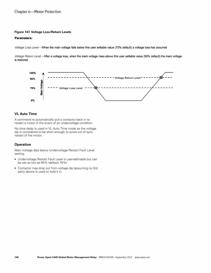
Chapter 6—Motor Protection
Figure 147. Voltage Loss/Return Levels
VL Auto Time
A command to automatically pull a contactor back in to restart a motor in the event of an undervoltage condition.
No time delay is used in VL Auto Time mode as the voltage dip is considered to be short enough to avoid out of sync restart of the motor.
Operation
Main Voltage dips below Undervoltage Restart Fault Level setting.
● Undervoltage Restart Fault Level is user-definable but can be set as low as 65% (default 70%)
● Contactor may drop out from voltage dip (assuming no 3rd party device is used to hold it in.
140 Power Xpert C445 Global Motor Management Relay MN042003EN—September 2015 www.eaton.com
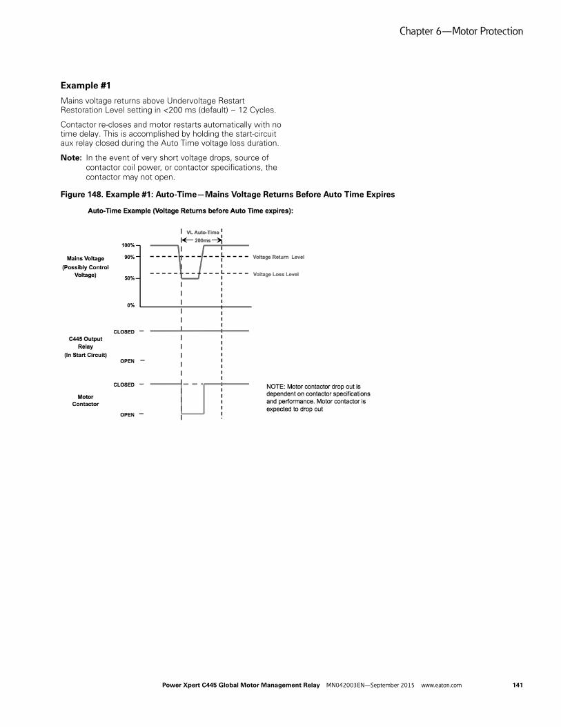
Chapter 6—Motor Protection
Example #1
Mains voltage returns above Undervoltage Restart Restoration Level setting in <200 ms (default) ~ 12 Cycles.
Contactor re-closes and motor restarts automatically with no time delay. This is accomplished by holding the start-circuit aux relay closed during the Auto Time voltage loss duration.
Note: In the event of very short voltage drops, source of contactor coil power, or contactor specifications, the contactor may not open.
Figure 148. Example #1: Auto-Time—Mains Voltage Returns Before Auto Time Expires
Power Xpert C445 Global Motor Management Relay MN042003EN—September 2015 www.eaton.com 141

Chapter 6—Motor Protection
Example #2
Mains voltage does not return above Undervoltage Restart Restoration Level setting in <200 ms (default) ~ 12 Cycles. In this case the contactor does not re-close and normal protections, if enabled, take over. The start circuit aux relay opens at the Auto Time Threshold. If the control voltage to the C445 is not being supplied by UPS or separate source, the C445 relay may power down from loss of control power and VL Short Time/VL Long Time restart protections cannot be utilized. If the control voltage to the C445 remains intact (UPS or separate source), the VL Short Time/VL Long Time restart protections can be utilized after VL Auto Time has expired.
Figure 149. Example #2: Auto-Time—Mains Voltage Does Not Return Before Auto Time Expires
142 Power Xpert C445 Global Motor Management Relay MN042003EN—September 2015 www.eaton.com
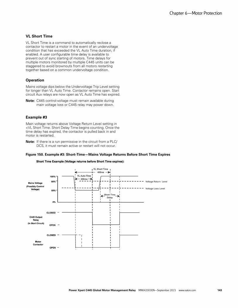
Chapter 6—Motor Protection
VL Short Time
VL Short Time is a command to automatically reclose a contactor to restart a motor in the event of an undervoltage condition that has exceeded the VL Auto Time duration, if enabled. A user configurable time delay is available to prevent out of sync starting of motors. Time delays for multiple motors monitored by multiple C445 units can be staggered to avoid brownouts from all motors restarting together based on a common undervoltage condition.
Operation
Mains voltage dips below the Undervoltage Trip Level setting for longer than VL Auto Time. Contactor remains open. Start circuit Aux relays are now open as VL Auto Time has expired.
Note: C445 control-voltage must remain available during main voltage loss or C445 relay may power down.
Example #3
Main voltage returns above Voltage Return Level setting in <VL Short Time. Short Delay Time begins counting. Once the time delay has expired, the contactor is pulled back in and motor is restarted.
Note: If there is a run permissive in the circuit from a PLC/DCS, it must remain active or restart will not occur.
Figure 150. Example #3: Short-Time—Mains Voltage Returns Before Short Time Expires
Power Xpert C445 Global Motor Management Relay MN042003EN—September 2015 www.eaton.com 143

Chapter 6—Motor Protection
Example #4
Main voltage does not return above Voltage Return Level setting in <VL Short Time. Contactor does not re-close.
Figure 151. Example #4: Short-Time—Mains Voltage Does Not Return Before Short Time Expires
144 Power Xpert C445 Global Motor Management Relay MN042003EN—September 2015 www.eaton.com
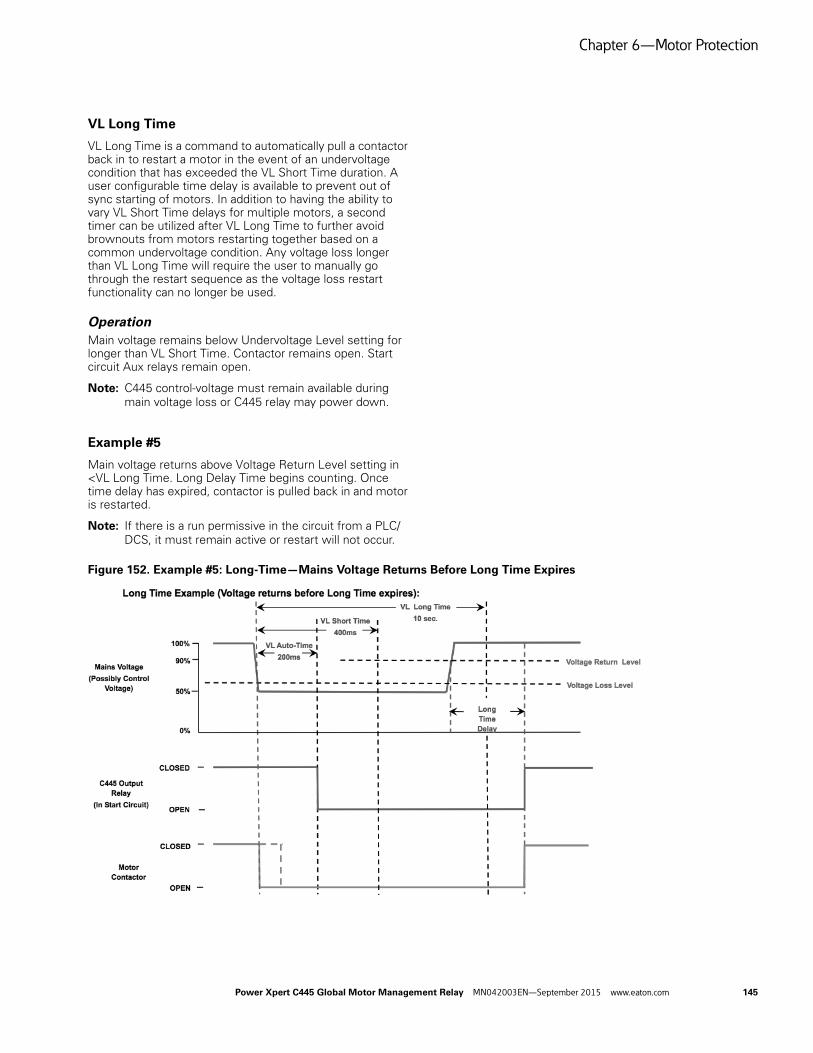
Chapter 6—Motor Protection
VL Long Time
VL Long Time is a command to automatically pull a contactor back in to restart a motor in the event of an undervoltage condition that has exceeded the VL Short Time duration. A user configurable time delay is available to prevent out of sync starting of motors. In addition to having the ability to vary VL Short Time delays for multiple motors, a second timer can be utilized after VL Long Time to further avoid brownouts from motors restarting together based on a common undervoltage condition. Any voltage loss longer than VL Long Time will require the user to manually go through the restart sequence as the voltage loss restart functionality can no longer be used.
OperationMain voltage remains below Undervoltage Level setting for longer than VL Short Time. Contactor remains open. Start circuit Aux relays remain open.
Note: C445 control-voltage must remain available during main voltage loss or C445 relay may power down.
Example #5
Main voltage returns above Voltage Return Level setting in <VL Long Time. Long Delay Time begins counting. Once time delay has expired, contactor is pulled back in and motor is restarted.
Note: If there is a run permissive in the circuit from a PLC/DCS, it must remain active or restart will not occur.
Figure 152. Example #5: Long-Time—Mains Voltage Returns Before Long Time Expires
Power Xpert C445 Global Motor Management Relay MN042003EN—September 2015 www.eaton.com 145

Chapter 6—Motor Protection
Example #6
Mains voltage does not return above Voltage Return Level setting in <VL Long Time. Contactor does not re-close and voltage loss restart has ended. User must manually go through restart sequence once voltage returns.
Figure 153. Example #6: Long-Time—Mains Voltage Does Not Return Before Long Time Expires
Protection and Monitoring
The C445 Base Control Module monitors several parameters for motor protection. The Power Xpert inControl Software provides two displays for parameter monitoring.
● The data analyzer graph is available to display changes in the values of the parameters.
● The monitoring menu displays all of the available monitoring parameters. The current values are shown in windows that are updated.
Trip Protection will stop the motor if select parameter values exceed set limits. There are data log records created and stored in non-volatile memory. These snapshots can be analyzed to determine the cause of failure. After a trip has occurred a restart feature may be configured to attempt to restart the motor.
146 Power Xpert C445 Global Motor Management Relay MN042003EN—September 2015 www.eaton.com

Chapter 6—Motor Protection
Advanced Protection Parameters
This table contains parameters that are applicable to all protections but are related to more advanced behavior.
Table 34. Protections
Parameter Units Min. Max. DefaultModbus Register Notes
Auto Reset Delay Sec 0 3600 180 1075 Time delay after a Fault Trip event occurs an auto-reset will be attempted
Backspin Inhibit Time Sec 0 3600 0 1077 Anti-backspin inhibit time before a reset is allowed
Fault Reset On Power Up Enable Disable Disable 1076 Enabled; perform a fault reset on power up Disabled; no action
Auto Reset Enable Disable Enable Disable 1072 Disabled; no auto reset functionality Enabled; auto reset functionality is based on trip auto-reset bit selections
Fault Trip Auto Reset Enable Bits 1073 Select Fault Trip Parameters to Auto Reset
Fault Trip Enable Bits Checked Unchecked Unchecked 1000 User input bit field that is used to enable or disable a protection function trip
Fault Warning Enable Bits Checked Unchecked Unchecked 1002 Only protections enabled by checking the associated box will provide a warning when that condition occurs
Positive Temperature Coefficient (PTC) (option)
376 0 = No Fault
1 = Overtemp
2 = Shorted
3 = Open
Fault Trip Code 22
Power Xpert C445 Global Motor Management Relay MN042003EN—September 2015 www.eaton.com 147

Chapter 6—Motor Protection
Motor Protection
The motor protections functions that are listed in this section monitor motor current (average, minimum, or maximum phase currents) to detect various motor running faults.
These protections functions may be disabled during a start. These protections are also disabled if the maximum phase current is less that 50% of the Motor FLA set-point.
Note: For protections functions to operate appropriately, the motor FLA must be configured for the application.
Use Power Xpert inControl to configure protection behaviors to navigate the selected device. The web page interface may also be used for navigation.
Offline Parameters R Control/Monitor Dashboard R Protections
Then follow the path to the protection settings.
Fault Warnings
Fault Warnings in many cases react to the same parameter values as Fault trips. Fault Warning events display the fault information but do not trip the controlled device. Similar to Fault Trips, Fault Warnings are subject to delay times noted in Modbus register 1079. This register sets the delay times for all Fault Warnings in all fault warnings protections.
Table 35. Fault Warnings
Fault ActionProtection Action Modbus Units Min. Max. Default
Fault Warning Fault Warning Delay 1079 ms 20 5000 2000
148 Power Xpert C445 Global Motor Management Relay MN042003EN—September 2015 www.eaton.com
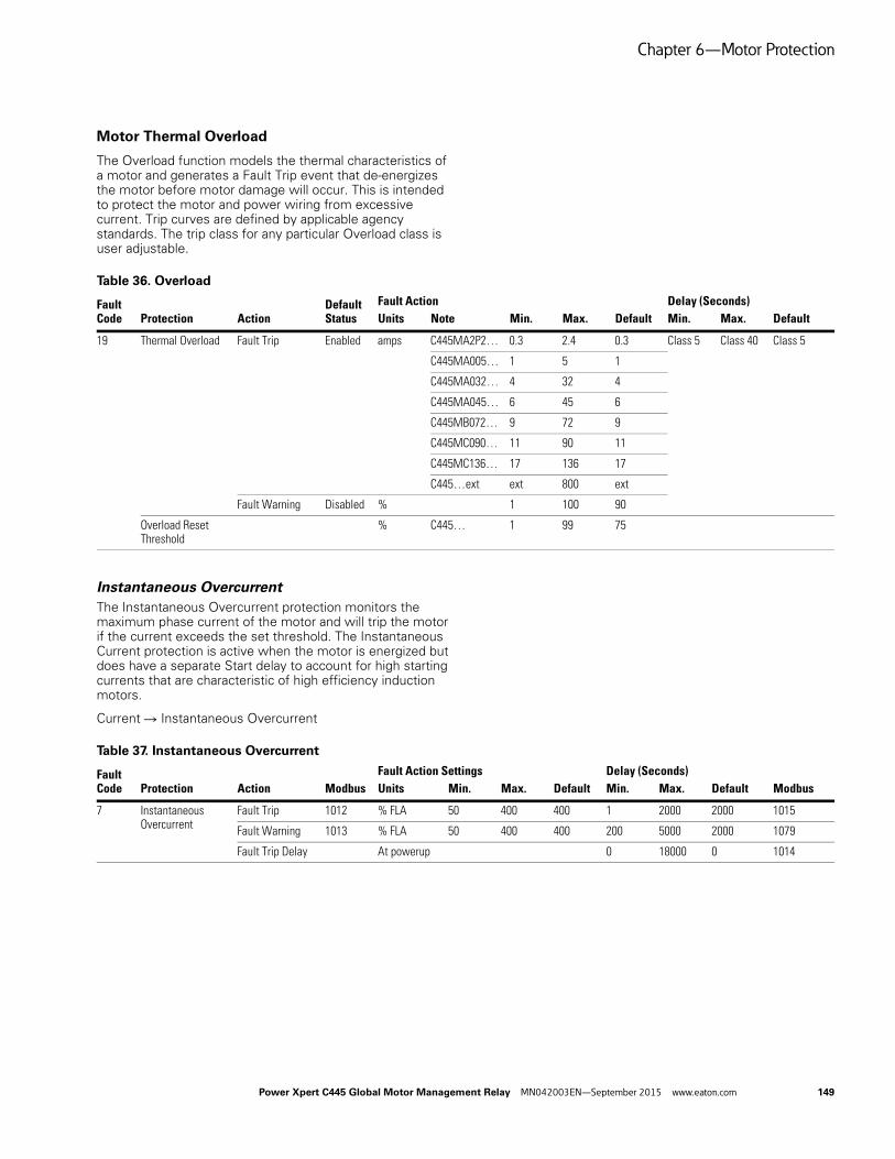
Chapter 6—Motor Protection
Motor Thermal Overload
The Overload function models the thermal characteristics of a motor and generates a Fault Trip event that de-energizes the motor before motor damage will occur. This is intended to protect the motor and power wiring from excessive current. Trip curves are defined by applicable agency standards. The trip class for any particular Overload class is user adjustable.
Table 36. Overload
Instantaneous OvercurrentThe Instantaneous Overcurrent protection monitors the maximum phase current of the motor and will trip the motor if the current exceeds the set threshold. The Instantaneous Current protection is active when the motor is energized but does have a separate Start delay to account for high starting currents that are characteristic of high efficiency induction motors.
Current R Instantaneous Overcurrent
Table 37. Instantaneous Overcurrent
Fault Code
Default Status
Fault Action Delay (Seconds)Protection Action Units Note Min. Max. Default Min. Max. Default
19 Thermal Overload Fault Trip Enabled amps C445MA2P2… 0.3 2.4 0.3 Class 5 Class 40 Class 5
C445MA005… 1 5 1
C445MA032… 4 32 4
C445MA045… 6 45 6
C445MB072… 9 72 9
C445MC090… 11 90 11
C445MC136… 17 136 17
C445…ext ext 800 ext
Fault Warning Disabled % 1 100 90
Overload Reset Threshold
% C445… 1 99 75
Fault Code Modbus
Fault Action Settings Delay (Seconds)Protection Action Units Min. Max. Default Min. Max. Default Modbus
7 Instantaneous Overcurrent
Fault Trip 1012 % FLA 50 400 400 1 2000 2000 1015
Fault Warning 1013 % FLA 50 400 400 200 5000 2000 1079
Fault Trip Delay At powerup 0 18000 0 1014
Power Xpert C445 Global Motor Management Relay MN042003EN—September 2015 www.eaton.com 149

Chapter 6—Motor Protection
JamThe C445 will monitor the average RMS value of the three phase currents. If the RMS value rises above the threshold for the required length of time a Fault is detected and the unit will trip. The Jam settings will only be active during the Motor Running state. The Jam protection feature can be disabled by modifying the TRIP ENABLE/DISABLE register over the network.
General R Trip Enable Bits R Jam
Table 38. Jam
StallThe Stall protection monitors the average phase current as a percentage of FLA of the motor and will trip the motor if the current exceeds the set threshold. The Stall protection is only active as the motor transitions from the Starting to Running states.
General R Stall Trip Level
Table 39. Stall 1
Note1 Only active during transition from start cycle to run cycle.
Current UnbalanceCurrent unbalance is defined using the following equation:
The C445 will monitor the Current Unbalance. If the value exceeds the threshold for the required length of time a fault is detected and the unit will trip. The Current Unbalance protection is enabled only in the Motor Running state.
Modifying the TRIP ENABLE/DISABLE register will enable or disable the Current Unbalance protection feature.
Current R I Unbalance
Table 40. Current Unbalance
Fault Code Modbus
Fault Action Delay (Seconds)Protection Action Units Min. Max. Default Min. Max. Default Modbus
8 Jam Fault Trip 1008 % FLA 50 400 400 1 60 5 1010
Fault Warning 1009 % FLA 50 400 400 0.2 5 2 1079
Fault Code Modbus
Fault Action Delay (Seconds)Protection Action Units Min. Max. Default Min. Max. Default Modbus
20 Stall Fault Trip 1007 % FLA 50 400 200 0 0 0
Fault Code Modbus
Fault Action Delay (Seconds)Protection Action Units Min. Max. Default Min. Max. Default Modbus
6 Current Unbalance Fault Trip 1018 % 1 60 15 1 60 15 1020
Fault Warning 1019 % 1 60 15 0.2 5 2 1079
150 Power Xpert C445 Global Motor Management Relay MN042003EN—September 2015 www.eaton.com

Chapter 6—Motor Protection
Current Phase LossThe Current Phase Loss protection monitors the current unbalance of the motor and will trip the motor if the unbalance exceeds the set threshold. The Current Phase Loss protection is active when the motor is in the Running state.
If a C445 relay is commissioned to monitor an AC motor, the current must be fed on all three poles to prevent early tripping.
Measurement Precondition Imax>50% of FLA, Imin<25% of FLA, No V Phase Loss (or no voltage option)
Measurement Parameter Current unbalance percent
Protections R Current R I Phase Loss
Table 41. Current Phase Loss
Undercurrent Undercurrent Trip Level protection monitors the three phase currents and will fault if the measured current drops below the set threshold.
Table 42. Undercurrent
Fault Code Modbus
Fault Action Delay (Seconds)Protection Action Units Min. Max. Default Min. Max. Default Modbus
5 Current Phase Loss Fault Trip 1016 % 60 60 60 2 2 2 1017
Fault Code Modbus
Fault Action Delay (Seconds)Protection Action Units Min. Max. Default Min. Max. Default Modbus
14 Undercurrent Fault Trip 1021 % FLA 10 90 50 1 60 20 1023
Fault Warning 1022 % FLA 10 90 50 0.2 5 2 1079
Power Xpert C445 Global Motor Management Relay MN042003EN—September 2015 www.eaton.com 151
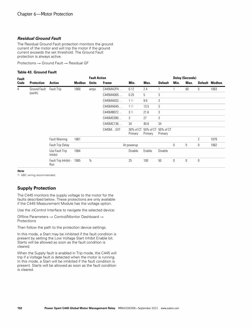
Chapter 6—Motor Protection
Residual Ground FaultThe Residual Ground Fault protection monitors the ground current of the motor and will trip the motor if the ground current exceeds the set threshold. The Ground Fault protection is always active.
Protections R Ground Fault R Residual GF
Table 43. Ground Fault
Note1 ABC wiring recommended.
Supply Protection
The C445 monitors the supply voltage to the motor for the faults described below. These protections are only available if the C445 Measurement Module has the voltage option.
Use the inControl Interface to navigate the selected device:
Offline Parameters R Control/Monitor Dashboard R Protections
Then follow the path to the protection device settings.
In this mode, a Start may be inhibited if the fault condition is present by setting the Low Voltage Start Inhibit Enable bit. Starts will be allowed as soon as the fault condition is cleared.
When the Supply fault is enabled in Trip mode, the C445 will trip if a Voltage fault is detected when the motor is running. In this mode, a Start will be inhibited if the fault condition is present. Starts will be allowed as soon as the fault condition is cleared.
Fault Code Modbus
Fault Action Delay (Seconds)Protection Action Units Frame Min. Max. Default Min. Max. Default Modbus
4 Ground Fault (earth)
Fault Trip 1060 amps C445MA2P4… 0.12 2.4 1 1 60 5 1063
C445MA005… 0.25 5 3
C445MA032… 1 1 9.6 3
C445MA045… 1 1 13.5 3
C445MB072… 3 1 21.6 3
C445MC090… 3 27 3
C445MC136… 34 40.8 34
C445M…EXT 30% of CT Primary
50% of CT Primary
50% of CT Primary
Fault Warning 1061 2 1079
Fault Trip Delay At powerup 0 5 0 1062
Use Fault Trip Inhibit
1064 Disable Enable Disable
Fault Trip Inhibit - Run
1065 % 25 100 50 0 0 0
152 Power Xpert C445 Global Motor Management Relay MN042003EN—September 2015 www.eaton.com

Chapter 6—Motor Protection
UndervoltageThe Undervoltage protection monitors the minimum phase voltage of the motor and will trip the motor if the voltage exceeds the set threshold. The Undervoltage protection is active when the motor is in the Running state. When the Low Voltage Start Inhibit Enable is set, the Undervoltage will prevent a start into an under voltage condition as determined by the Undervoltage Start Inhibit Level.
Protections R Voltage R Undervoltage
Table 44. Undervoltage
OvervoltageThe Overvoltage protection monitors the maximum phase voltage of the motor and will trip the motor if the voltage exceeds the set threshold. The Overvoltage protection is active when the motor is in the Running state.
Protections R Voltage R Overvoltage
Table 45. Overvoltage
Fault Code Modbus
Fault Action Delay (Seconds)Protection Action Units Min. Max. Default Min. Max. Default Modbus
1 Undervoltage Fault Trip 1028 % 10 100 90 1 60 20 1031
Fault Warning 1029 % 10 100 90 0.2 5 2 1079
Start Trip Delay Delay Fault Trip at Startup 0 60 20 1030
Fault Code Modbus
Fault Action Delay (Seconds)Protection Action Units Min. Max. Default Min. Max. Default Modbus
2 Overvoltage Fault Trip 1025 % 90 150 110 1 60 20 1027
Fault Warning 1026 % 90 150 110 0.2 5 2 1079
Power Xpert C445 Global Motor Management Relay MN042003EN—September 2015 www.eaton.com 153

Chapter 6—Motor Protection
Voltage UnbalanceVoltage Unbalance is estimated using the following equation.
The Voltage Unbalance protection monitors the voltage unbalance percentage of the supply and will trip the motor if the voltage exceeds the set threshold. The Voltage Unbalance protection is active when the motor is in the energized state. When the Voltage unbalance Start Inhibit protection is enabled, the Undervoltage protection will prevent a start into an unbalanced condition as determined by the Unbalance Start Inhibit Level.
Protections R Voltage R V Unbalance
Table 46. Voltage Unbalance
Voltage Phase Loss The Voltage Phase Loss protection monitors the phase voltage of the motor and will trip the motor if the voltage falls below 70% of the nominal mains voltage.
Table 47. Voltage Phase Loss
Fault Code Modbus
Fault Action Delay (Seconds)Protection Action Units Min. Max. Default Min. Max. Default Modbus
11 Voltage Unbalance Fault Trip 1043 % 1 20 6 1 60 20 1045
Fault Warning 1044 % 1 20 6 0.2 5 2 1079
Fault Code Modbus
Fault Action Delay (Seconds)Protection Action Units Min. Max. Default Min. Max. Default Modbus
11 Voltage Phase Loss Fault Trip 1041 % 70 70 70 2 2 2 1042
154 Power Xpert C445 Global Motor Management Relay MN042003EN—September 2015 www.eaton.com

Chapter 6—Motor Protection
Phase RotationThe Phase Sequence protection monitors the sequence of the supply. A fault will be generated if the supply sequence does not match the configured setting. The phase sequence protection is always active.
Protections R General R Phase Rotation Protection
Table 48. Voltage Phase Rotation
Power Factor Deviation
The Power Factor (PF) Deviation protection monitors the PF (supply side) of the load and will trip the motor if the measured deviation from rated exceeds the set threshold.
The power factor deviation protection is active when the motor is in the running state.
Measurement Precondition Vavg > 40 volts RMS & Iavg RMS > 50% of FLA.
Protections R Power R PF Deviation
Table 49. PF Deviation
Fault Code Modbus
Fault Action Delay (Seconds)Protection Action Units Value Max. Default Min. Max. Default Modbus
21 Phase Rotation Fault Trip 1024 0 Off 1 0 0 0
1 ABC 1 0 0 0
2 ACB 1 0 0 0
Fault Code Modbus
Fault Action Delay (Seconds)Protection Action Units Min. Max. Default Min. Max. Default Modbus
9 Power Factor Deviation Low
Fault Trip 1056 % –10000 10000 0 1 60 20 1059
Fault Warning 1058 % –10000 10000 0 1 60 2 1079
9 Power Factor Deviation High
Fault Trip 1055 % –10000 10000 10000 1 60 20 1059
Fault Warning 1057 % –10000 10000 10000 1 60 2 1079
Power Xpert C445 Global Motor Management Relay MN042003EN—September 2015 www.eaton.com 155

Chapter 6—Motor Protection
Frequency Deviation (Slow)The Frequency Deviation (Slow) protection monitors the line frequency of the supply and will trip the motor if the deviation from rated exceeds the set threshold. The Frequency Deviation protection is active when the motor is in the Energized state.
Protections R Frequency R Frequency Deviation Slow
Table 50. Hz Dev – Slow
Frequency Deviation (Fast)The Frequency Deviation (Fast) protection monitors the line frequency of the supply and will trip the motor if the deviation from rated exceeds the set threshold. The Frequency Deviation protection is active when the motor is in the Energized state.
Protections R Frequency R Frequency Deviation Fast
Table 51. Hz Dev – Fast
Load Protection
Use the inControl Interface to navigate the selected device:
Offline Parameters R Control/Monitor Dashboard R Protections
Then follow the path to the protection device settings.
UndercurrentThe Undercurrent protection monitors the average current of the motor and will trip the motor if the unbalance drops below the set threshold. The Undercurrent protection is active when the motor is in the Running state.
Protections R Current R Undercurrent
Table 52. Undercurrent
Fault Code Modbus
Fault Action Delay (Seconds)Protection Action Units Min. Max. Default Min. Max. Default Modbus
13 Frequency Deviation (Slow)
Fault Trip 1069 0.01 Hz 10 500 10 1 60 20 1071
Fault Warning 1070 0.01 Hz 10 500 10 1 60 2 1079
Fault Code Modbus
Fault Action Delay (Seconds)Protection Action Units Min. Max. Default Min. Max. Default Modbus
12 Frequency Deviation (Fast)
Fault Trip 1066 0.01 Hz 2 200 10 20 2000 1000 1068
Fault Warning 1067 0.01 Hz 2 200 10 20 2000 2000 1079
Fault Code Modbus
Fault Action Delay (Seconds)Protection Action Units Min. Max. Default Min. Max. Default Modbus
14 Undercurrent Fault Trip 1021 % FLA 10 90 50 1 60 20 1023
Fault Warning 1022 % FLA 10 90 50 1 60 2 1079
156 Power Xpert C445 Global Motor Management Relay MN042003EN—September 2015 www.eaton.com
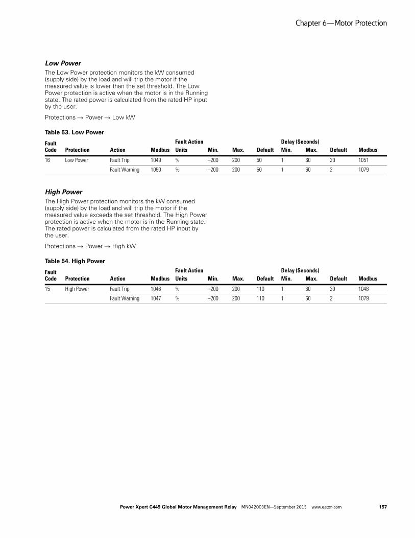
Chapter 6—Motor Protection
Low PowerThe Low Power protection monitors the kW consumed (supply side) by the load and will trip the motor if the measured value is lower than the set threshold. The Low Power protection is active when the motor is in the Running state. The rated power is calculated from the rated HP input by the user.
Protections R Power R Low kW
Table 53. Low Power
High PowerThe High Power protection monitors the kW consumed (supply side) by the load and will trip the motor if the measured value exceeds the set threshold. The High Power protection is active when the motor is in the Running state. The rated power is calculated from the rated HP input by the user.
Protections R Power R High kW
Table 54. High Power
Fault Code Modbus
Fault Action Delay (Seconds)Protection Action Units Min. Max. Default Min. Max. Default Modbus
16 Low Power Fault Trip 1049 % –200 200 50 1 60 20 1051
Fault Warning 1050 % –200 200 50 1 60 2 1079
Fault Code Modbus
Fault Action Delay (Seconds)Protection Action Units Min. Max. Default Min. Max. Default Modbus
15 High Power Fault Trip 1046 % –200 200 110 1 60 20 1048
Fault Warning 1047 % –200 200 110 1 60 2 1079
Power Xpert C445 Global Motor Management Relay MN042003EN—September 2015 www.eaton.com 157
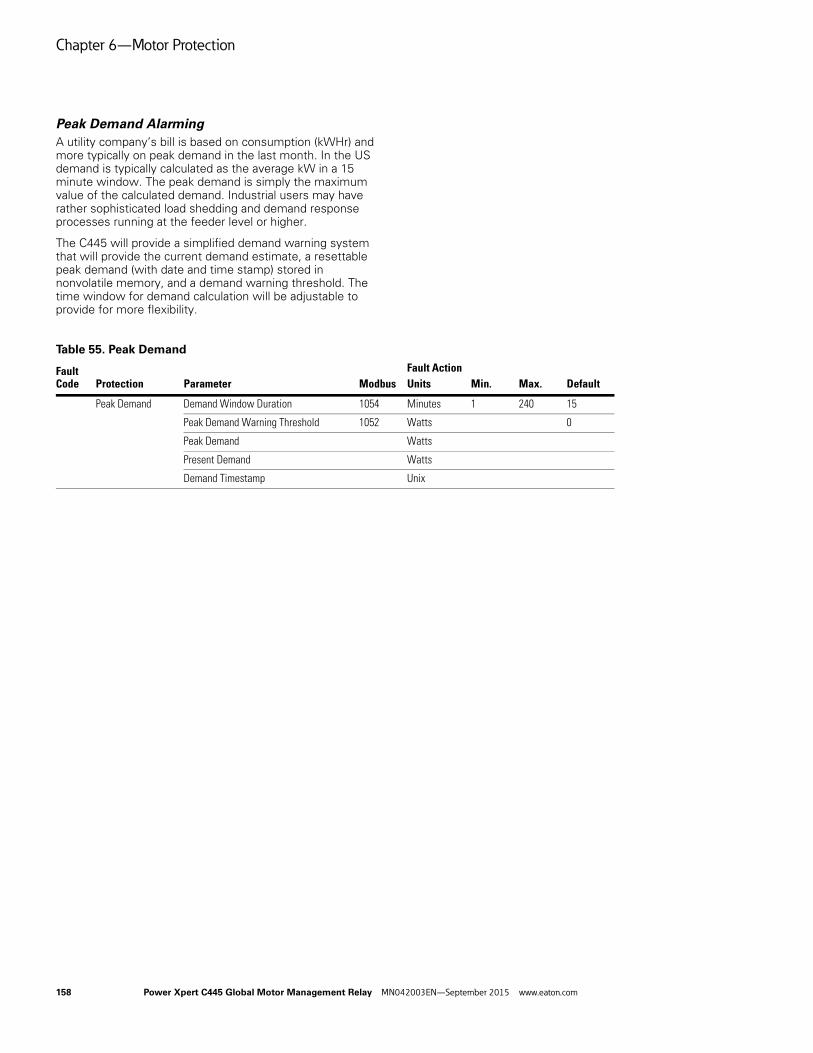
Chapter 6—Motor Protection
Peak Demand AlarmingA utility company’s bill is based on consumption (kWHr) and more typically on peak demand in the last month. In the US demand is typically calculated as the average kW in a 15 minute window. The peak demand is simply the maximum value of the calculated demand. Industrial users may have rather sophisticated load shedding and demand response processes running at the feeder level or higher.
The C445 will provide a simplified demand warning system that will provide the current demand estimate, a resettable peak demand (with date and time stamp) stored in nonvolatile memory, and a demand warning threshold. The time window for demand calculation will be adjustable to provide for more flexibility.
Table 55. Peak Demand
Fault Code Modbus
Fault ActionProtection Parameter Units Min. Max. Default
Peak Demand Demand Window Duration 1054 Minutes 1 240 15
Peak Demand Warning Threshold 1052 Watts 0
Peak Demand Watts
Present Demand Watts
Demand Timestamp Unix
158 Power Xpert C445 Global Motor Management Relay MN042003EN—September 2015 www.eaton.com

Chapter 7—Monitoring and Diagnostics
Chapter 7—Monitoring and Diagnostics
Methods for Monitoring
There are a number of different ways to monitor operating parameters from a C445 Motor Management Relay System.
One way to monitor operating parameters from a C445 is to use the Power Xpert inControl Software Tool. All available parameters are viewable from this software and the most common operating parameters are located in a Control/Monitor (Dashboard) category, while other parameters related to current, voltage, power and system parameters are categorized under a Measurement category. In addition, there is a Faults and Events category where all active faults, warnings and inhibits are displayed, along with the 10-deep fault queue and snap shot values. Snap shot values are parameters values saved with the last fault code to provide more detailed information on that fault, such a current values, power factor, thermal memory, voltages, power and more.
Another way to monitor operating parameters from a C445 is via a fieldbus network from the system controller. If a fieldbus network such as EtherNet/IP, Modbus serial, Modbus TCP or PROFIBUS are being used for control, the master controller on these networks can monitor operating parameters constantly with other input and output polled/cyclic data or via specific one-time acyclic/explicit messages only when an event occurs.
The C445 supports both implicit polled messages as well as explicit messages of all operating parameters on EtherNet/IP.
The C445 supports acyclic DPV1 messages on PROFIBUS as well as cyclic messages used for control and monitoring on a constant basis. All operating parameters are supported for both types of messages.
For Modbus serial and Modbus TCP, all parameters including all operating parameters are available to monitor. Appendix E contains a complete list of all parameters and their associated Modbus register address.
An operator interface or HMI device can also be used to monitor operating parameters from a C445 via any of the above supported fieldbus networks.
Power Xpert C445 Global Motor Management Relay MN042003EN—September 2015 www.eaton.com 159

Chapter 7—Monitoring and Diagnostics
Monitoring Parameters
A list and description of the available operating parameters for monitoring is shown below.
Table 56. Current Based Monitoring
Parameter Name Range/Units Description
IA (L1) float Depends on frame size (amps) Phase A (L1) motor current. 2% accuracy within 30–125% of FLA.
IB (L2) float Depends on frame size (amps) Phase B (L2) motor current. 2% accuracy within 30–125% of FLA.
IC (L3) float Depends on frame size (amps) Phase C (L3) motor current. 2% accuracy within 30–125% of FLA.
I average float Depends on frame size (amps) Average motor current. 2% accuracy within 30–125% of FLA.
I unbalance percent 0–100% Motor current unbalance percent
I average % of FLA (nominal current)
0–720% of FLA (amps) Average motor current as a percentage of FLA
Maximum start current floating point
Depends on frame size (amps) Maximum motor starting current
Motor residual GF RMS Depends on frame size (amps), scaled via fieldbus
Motor residual ground fault current RMS. Accuracy meets UL-1053 / IEC Class II-B
IA (L1) scaled Depends on frame size (amps, scaled) Phase A (L1) motor current scaled. Scaled by parameter “I Scale Factor.”
IB (L2) scaled Depends on frame size (amps, scaled) Phase B (L2) motor current scaled. Scaled by parameter “I Scale Factor.”
IC (L3) scaled Depends on frame size (amps, scaled) Phase C (L3) motor current scaled. Scaled by parameter “I Scale Factor.”
I average scaled Depends on frame size (amps, scaled) Average motor current scaled. Scaled by parameter “I Scale Factor.”
I scale factor Motor current scale factor
Table 57. Voltage Based Monitoring
Parameter Name Range/Units Description
Voltage AB (L1-L2) 0–690 V; max 4,160 V with PT ratios Supply line-to-line voltage AB (L1-L2). 2% accuracy up to 690 Vac
Voltage BC (L2-L3) 0–690 V; max 4,160 V with PT ratios Supply line-to-line voltage BC (L2-L3). 2% accuracy up to 690 Vac
Voltage CA (L3-L1) 0–690 V; max 4,160 V with PT ratios Supply line-to-line voltage CA (L3-L1). 2% accuracy up to 690 Vac
Average line-to-line voltage 0–690 V; max 4,160 V with PT ratios Supply line-to-line voltage average. 2% accuracy up to 690 Vac
Line frequency x 100 47–63 Hz (centi-Hz) Supply frequency in centi-Hz
Voltage phase order 0: unknown;1: ABC (L1-L2-L3); 2: ACB (L1-L3-L2)
Reports phase sequence of the line voltage
Voltage unbalance percent 0–100% Supply voltage unbalance percentage
VAB (L1-L2) scaled V, scaled Supply line-to-line voltage AB (L1-L2) scaled
VBC (L2-L3) scaled V, scaled Supply line-to-line voltage BC (L2-L3) scaled
VCA (L3-L1) scaled V, scaled Supply line-to-line voltage CA (L3-L1) scaled
Average line-to-line voltage scaled
V, scaled Supply line-to-line voltage average scaled
Voltage scale Voltage scale factor applied to scaled voltage measurements
160 Power Xpert C445 Global Motor Management Relay MN042003EN—September 2015 www.eaton.com
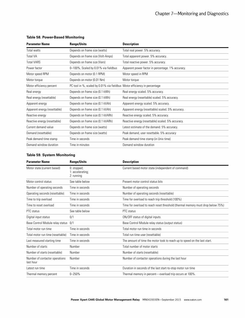
Chapter 7—Monitoring and Diagnostics
Table 58. Power-Based Monitoring
Parameter Name Range/Units Description
Total watts Depends on frame size (watts) Total real power. 5% accuracy.
Total VA Depends on frame size (Volt-Amps) Total apparent power. 5% accuracy.
Total VARS Depends on frame size (Vars) Total reactive power. 5% accuracy.
Power factor 0–100%, Scaled by 0.01% via fieldbus Apparent power factor in percentage. 1% accuracy.
Motor speed RPM Depends on motor (0.1 RPM) Motor speed in RPM
Motor torque Depends on motor (0.01 Nm) Motor torque
Motor efficiency percent PC tool in %, scaled by 0.01% via fieldbus Motor efficiency in percentage
Real energy Depends on frame size (0.1 kWh) Real energy scaled. 5% accuracy.
Real energy (resettable) Depends on frame size (0.1 kWh) Real energy (resettable) scaled. 5% accuracy.
Apparent energy Depends on frame size (0.1 kVAh) Apparent energy scaled. 5% accuracy.
Apparent energy (resettable) Depends on frame size (0.1 kVAh) Apparent energy (resettable) scaled. 5% accuracy.
Reactive energy Depends on frame size (0.1 kVARh) Reactive energy scaled. 5% accuracy.
Reactive energy (resettable) Depends on frame size (0.1 kVARh) Reactive energy (resettable) scaled. 5% accuracy.
Current demand value Depends on frame size (watts) Latest estimate of the demand. 5% accuracy.
Demand (resettable) Depends on frame size (watts) Peak demand, user resettable. 5% accuracy
Peak demand time stamp Time in seconds Peak demand time stamp (in Unix time)
Demand window duration Time in minutes Demand window duration
Table 59. System Monitoring
Parameter Name Range/Units Description
Motor state (current based) 0: stopped;1: accelerating;2: running
Current based motor state (independent of command)
Motor control status See table below Present motor control status bits
Number of operating seconds Time in seconds Number of operating seconds
Operating seconds (resettable) Time in seconds Number of operating seconds (resettable)
Time to trip overload Time in seconds Time for overload to reach trip threshold (100%)
Time to reset overload Time in seconds Time for overload to reach reset threshold (thermal memory must drop below 75%)
PTC status See table below PTC status
Digital input status 0/1 ON/OFF status of digital inputs.
Base Control Module relay status 0/1 Base Control Module relay status (output status)
Total motor run time Time in seconds Total motor run time in seconds
Total motor run time (resettable) Time in seconds Total run time user (resettable)
Last measured starting time Time in seconds The amount of time the motor took to reach up to speed on the last start.
Number of starts Number Total number of motor starts
Number of starts (resettable) Number Number of starts (resettable)
Number of contactor operations last hour
Number Number of contactor operations during the last hour
Latest run time Time in seconds Duration in seconds of the last start-to-stop motor run time
Thermal memory percent 0–250% Thermal memory in percent—overload trip occurs at 100%.
Power Xpert C445 Global Motor Management Relay MN042003EN—September 2015 www.eaton.com 161

Chapter 7—Monitoring and Diagnostics
Table 60. Faults and Events
Parameter Name Range/Units Description
Active fault See Table 61 below Active fault
Active warning See Table 61 below Active warning
Active inhibit See Table 61 below Active inhibit
Fault queue—event order See Table 61 below A list of the last 10 faults shown in the order they occurred. Most recent at top.
Table 61. Trip Snapshot Parameters
Parameter Name Range/Units Description
Snap shot phase A (L1) current Depends on frame size (Amps) Phase A (L1) RMS current at time of trip
Snap shot phase B (L2) current Depends on frame size (Amps) Phase B (L2) RMS current at time of trip
Snap shot phase C (L3) current Depends on frame size (Amps) Phase C (L3) RMS current at time of trip
Snap shot ground current Depends on frame size (Amps) Ground fault current RMS at time of trip
Snap shot frequency 47–63 Hz (centi-Hz) Line frequency at time of trip scaled in centi-Hz
Snap shot thermal memory 0–250% Overload thermal memory percent at time of trip
Snap shot voltage AB (L1-L2) 0–690 V; max 4,160 V with PT ratios Voltage AB (L1-L2) RMS volts at time of trip
Snap shot voltage BC (L2-L3) 0–690 V; max 4,160 V with PT ratios Voltage BC (L2-L3) RMS volts at time of trip
Snap shot voltage CA (L3-L1) 0–690 V; max 4,160 V with PT ratios Voltage CA (L3-L1) RMS volts at time of trip
Snap shot VA Depends on frame size (volt-amps) Apparent power at time of trip
Snap shot watts Depends on frame size (Watts) Real power at time of trip
Snap shot power factor 0–100%, scaled by 0.01% via fieldbus Power factor at time of trip
Table 62. PTC Status Bits
Value Description
0 PTC OK—no fault
1 PTC over temperature fault
2 PTC shorted fault
3 PTC open fault
Table 63. Motor Control Status Bits
Value Description Coil
0 Running 1 4785
1 Running 2 4786
2 Remote enabled 4787
3 Faulted 4788
4 Warning 4789
5 Inhibited 4790
6 Ready 4791
7 Motor at speed 4792
162 Power Xpert C445 Global Motor Management Relay MN042003EN—September 2015 www.eaton.com

Chapter 7—Monitoring and Diagnostics
Table 64. Active Fault, Warning andInhibit Values
Value Description
Active Fault
0 No Faults
1 Under voltage
2 Over voltage
3 External GF
4 Residual GF
5 Current phase loss
6 Current unbalance
7 Instantaneous over current
8 Jam
9 PF Deviation
10 Voltage phase loss
11 Voltage unbalance
12 Frequency deviation fast
13 Frequency deviation slow
14 Under current
15 High power
16 Low power
17 Contactor failure
18 Starts limit exceeded
19 Overload
20 Stall
21 Phase rotation mismatch
22 PTC - See PTC State for details
23 Under voltage restart
24 Measurement Module fault
25 Communication loss on active fieldbus
26 Measurement Module not available or communication loss with the module
27 User Interface not available or communication loss with the module
28 Test trip was triggered
29 Option Card not available or communication loss with the module
30 RTC / Backup Memory Option Board NV memory fail
31 Currently connected User Interface does not match with what was connected before
32 Currently connected Measurement Module does not match with what was connected before
33 Currently connected Option Card does not match with what was connected before
Active Fault, continued
34 Measurement Module firmware is incompatible
35 User Interface firmware is incompatible
36 Ethernet Option Card firmware is incompatible
37 Profi Option Card firmware is incompatible
500 Internal - communication loss with Power Supply Board
501 Internal - Power Supply Board is not responding to SPI
502 Internal - Checksums in NV memory (FRAM) didn't match during read (neither pair)
503 Internal - Checksums in NV memory (FRAM) didn't match during write (neither pair)
504 Internal - RTC / Backup Memory Option Card is missing
505 Internal - RTC / Backup Memory Option Card does not match actual
506 Internal - RTC / Backup Memory Option Card has NV Fault.
507 Internal - serial flash memory fault (Attempt Factory Reset first. Return to manufacturer if not cleared)
508 Internal - logic mapping error (Attempt factory reset)
509 Internal - CUI NV memory error
510 Internal - Option card NV memory error
Active Warning
0 No Warnings
1 Under voltage
2 Over voltage
3 External GF
4 Residual GF
5 Current phase loss
6 Current unbalance
7 Instantaneous over current
8 Jam
9 PF Deviation
10 Voltage phase loss
11 Voltage unbalance
12 Frequency deviation fast
13 Frequency deviation slow
14 Under current
15 High power
16 Low power
17 Contactor failure
Table 64. Active Fault, Warning andInhibit Values, continued
Value Description
Power Xpert C445 Global Motor Management Relay MN042003EN—September 2015 www.eaton.com 163

Chapter 7—Monitoring and Diagnostics
Active Warning, continued
18 Starts limit exceeded
19 Overload
20 Stall
21 Phase rotation mismatch
22 PTC - See PTC State for details
23 Peak demand
24 Measurement Module warning
25 Real Time Clock requires setting (has not been set)
26 RTC Battery Low. Replacement is recommended
27 Device ambient temperature high
28 MM high ambient temperature
29 CUI high ambient temperature
30 Option card high ambient temperature
Active Inhibit
0 No inhibits
1 Incorrect configuration. See configuration inhibit reason
2 A soft reset is required
3 Backspin prevention
4 Under voltage restart timer active
5 Control voltage is low
6 Under voltage condition
7 Voltage unbalance
8 Starts per hour limit has been exceeded
9 Over voltage condition
Table 64. Active Fault, Warning andInhibit Values, continued
Value Description
164 Power Xpert C445 Global Motor Management Relay MN042003EN—September 2015 www.eaton.com

Appendix A—Technical Data and Specifications
Appendix A—Technical Data and Specifications
Communications Isolation Notes
The isolation between the Modbus Port and BCM electronics is functional isolation only. All connections to the Modbus terminal shall meet PELV requirements.
The isolation between the PROFIBUS Port and BCM electronics is functional isolation only. All connections to the PROFIBUS Port terminal shall meet PELV requirements.
The isolation between the Ethernet Port and BCM electronics is functional isolation only. All connections to the Ethernet Port terminal shall meet SELV/PELV requirements.
Table 65. Environmental Specifications
Table 66. Power Supply Specifications Summary
Notes1 Fuse information—Recommend 1 A slow blow fuse for AC control power. Interrupting capability should be
greater than available branch current.2 UL Listed Isolated Class 2/PELV Power Supply Rated Maximum 24 Vdc. Wiring must meet
PELV requirements.3 Base Control Module + Measurement Module + User Interface + Communication Card.
Description Specification
Temperature –40 °C to 85 °C (–40 °F to 185 °F), non-operating–40 °C to 60 °C (–40 °F to 140 °F), operating
Operating Humidity 5–95% non-condensing
Altitude NEMA ICS1 2000 meters (6600 feet)
Shock IEC 60068-2-27 15 g any direction for 11 milliseconds, non-operating
Vibration IEC 60068-2-6 5 g non-operating and 3 g operating in any direction
Pollution Degree 3
Protection Degree Internal Components: IP20 User Interface: IP54 & UL Type12
Cooling Convection (natural)
Description Specification
AC Control Power 1 Rated supply voltage (operating range):110–120 Vac/60 Hz, (94–132 Vac)220–240 Vac/50 Hz, (187–264 Vac)
Requirement of an external control power transformer when the product is used above 150 Vac (220–240 Vac)
DC Control Power 2 Rated supply voltage (operating range):24 Vdc Nominal (18–30 Vdc)
The common terminal of the 24 V power supply shall be earthed
Max. Power Consumption 3 8 W
AC Control Power Input Impulse Withstand Voltage Uimp
See Table 77.
Power Xpert C445 Global Motor Management Relay MN042003EN—September 2015 www.eaton.com 165

Appendix A—Technical Data and Specifications
Table 67. Input/Output Specifications
Table 68. PTC Specifications
Description Specification
Relay Rating Relay Q1 / Q2 (from A – NO)B300 Pilot Duty, R300 Pilot DutyAC-15: 3 A at 120 Vac, 1.5 A at 240 VacDC-13: 0.22 at 125 Vdc, 0.1 at 250 Vdc, 2 A at 24 Vdc
Relay Q3 (from C – latching)B300 Pilot Duty, R300 Pilot DutyAC-15: 3 A at 120 Vac, 1.5 A at 240 VacDC-13: 0.22 at 125 Vdc, 0.1 at 250 Vdc, 1.5 A at 24 Vdc
Relay Q3 (from C – non-latching)B300 Pilot Duty, R300 Pilot DutyAC-15: 3 A at 120 Vac, 1.5 A at 240 VacDC-13: 0.22 at 125 Vdc, 0.1 at 250 Vdc, 2 A at 24 Vdc
The Q3 normally closed relay contacts should not be used for motor contactor control
AC Field Input 1 IEC 61131-2 Type 1 Digital InputOff State: 0 Vac to 20 VacOn State: 79 Vac to 132 VacMax. ON current: 15 mA
DC Field Input IEC 61131-2 Type 1 Digital InputOff State: 0 Vac to 5 VdcOn State: 15 Vdc to 30 VdcMax. ON current: 15 mA
Mandatory Short Circuit Protection for Auxiliary Contacts (relay outputs)
6 A Class gG fuse (IEC 60947-5-1)
Terminal Block Wiring capacity: 0.2 mm2 (24 AWG) to 2.5 mm2 (12 AWG)
Use only UL listed or recognized conductors. Copper wire rated 75C (75°C UC wire) for all field wiring terminals and main overload conductor wiring.
Description Specification
Standard EN 60947-8/A1:2006 “Mark A Control Unit”
Compatible Thermal Detectors MARK A type (abrupt characteristic change) as described in EN 60947-8/A1:2006 Annex A wired in series
Terminals Marked T1 & T2.0.2 mm2 (24 AWG) to 2.5 mm2 (12 AWG)
Cold Resistance <= 1500 ohms
Measuring Voltage T1-T2 <= 2.5 V for resistance <= 1330 ohms<= 7.5 V for resistance <= 4 kohms<= 9.0 V open circuit
Temperature Rise Response 3600 ohms ±10%
Over Temperature Reset 1500 ohms ±10%
Short Circuit Response Between 10 and 20 ohms
Short Circuit Reset Between 20 and 40 ohms
Wire Break Response 20 k to 40 kohms
Isolation See Table 77.
166 Power Xpert C445 Global Motor Management Relay MN042003EN—September 2015 www.eaton.com

Appendix A—Technical Data and Specifications
Table 69. Measurement Module Specifications
Table 70. Measurement Module Frame Breaks
Notes1 Use only insulated conductors.Conductor outer diameter vary with insulation type.
Refer to aperture diameter for sizing. 2 Linear to 1.2 FLA over the range of 20–80 Hz. Linear to 7.2x FLA over 47–63 Hz range.
Table 71. EMC Emissions
Description Specification
3 Phase Voltage input U12, U23, U31 RMS
Input ratings: 110–690 Vac (94–759 Vac)Grounded, Floating, and High-Resistance Ground Distribution systems supported.4160 Vac with PT Ratios between 35:1 and 6:1
Connector: Removable screw terminal
Uimp: See Table 77.
Line Frequency: 20~80 Hz
3 Phase Current input I1, I2, I3 RMS
Depending on Measurement Module range
Current as % of rated FLA0~720% max rated FLA
FrameSize Current Range
Aperture Dia. (mm)
Supported Conductor NA 600 V 1
Supported Conductor EMEA 690 V 1 Frequency Range
45 mm 0.3–2.4 Amp 7.8 6 AWG 16 mm2 20–80 Hz 2
45 mm 1–5 Amp 7.8 6 AWG 16 mm2 20–80 Hz 2
45 mm 4–32 Amp 7.8 6 AWG 16 mm2 20–80 Hz 2
45 mm 6–45 Amp 7.8 6 AWG 16 mm2 20–80 Hz 2
55 mm N.A. 9-68 Amp 1IEC 9-72 Amp
10.5 3 AWG 25 mm2 20–80 Hz 2
90 mm 11–90 Amp 15.8 2/0 AWG 70 mm2 20–80 Hz 2
90 mm 17–136 Amp 15.8 2/0 AWG 70 mm2 20–80 Hz 2
Description Specification
Radiated Emissions EN 55011 (CISPIR 11) Group 1, Class A, ISM Equipment for Industrial, Scientific, and Medical Equipment. 30 MHz to 1000 Mhz
The ferrite bead needs to be applied to meet requirements. Bead should go over L1 and L2 terminals only.
Conducted Emissions IEN 55011 (CISPIR 11) Group 1, Class A, ISM Equipment for Industrial, Scientific, and Medical Equipment. 0.15 MHz to 30 MHz.
The ferrite bead needs to be applied to meet requirements. Bead should go over L1 and L2 terminals only.
Power Xpert C445 Global Motor Management Relay MN042003EN—September 2015 www.eaton.com 167

Appendix A—Technical Data and Specifications
Table 72. EMC Immunity
Table 73. Agency Certifications and Regulatory
Note1 ATEX Certification will apply to BCM, PROFIBUS option card, Ethernet option card, and MM (including PTC option
to satisfy NAMUR requirements).
Description Specification
Surge 61000-4-5Criteria B
2 kV Line to Earth1 kV Line to Line
ESD 61000-4-2Criteria B
8 kV air discharge4 kV contact discharge
EFT 61000-4-4Criteria B
Power Ports: 2 kV, 5 kHz, Direct MethodSignal Ports: 1 kV, 5 kHz, Clamp Method
Radiated Immunity 61000-4-3Criteria A
10 V/m 80–2000 MHz, 80% amplitude modulation at 1 kHz1 V/m 2000–2700 MHz, 80% amplitude modulation at 1 kHz
Conducted Immunity 61000-4-6Criteria A
10 V/m, 0.15–80 MHz, 80% amplitude modulation a 1 kHz
Magnetic Field Immunity 61000-4-8Criteria A
30 A/m, 50/60 Hz
Voltage Dips & Interruptions 61000-4-11Criteria A
110 Vac 60 Hz, 220 Vac 50 Hz0% rated voltage during 1/2 cycle0% rated voltage during 1 cycle70% rated voltage during 25/30 cycles
Voltage Interruptions 61000-4-11Criteria A
110 Vac 60 Hz, 220 Vac 50 HzInterruption (0% rated voltage) during 250/300 cycles
Voltage Interruptions 61000-4-29Criteria A
24 VdcInterruption (0% rated voltage) for 10 ms
Description Specification
Agency Certifications UL and CSA
UL 60947-4-1
CSA 22.2 #60947-4-1
CSA C22.2 NO. 0-10
Low Voltage directive (2006/95/EC)IEC/EN 60947-4-1IEC/EN 60947-5-1EN 60947-8
ATEX 95 (directive 94/9/EC) 1 [Ex I (M2), Ex II (2) GD], EN 50495:2010 (to SIL 1)
EN 60079-7 (For increased safety method of protection of Ex e motor), EMC directive (2004/108/EC),Machine Directive (2006/42/EC), IEC/EN 61000-4 level 3,PROFIBUS/ODVA Conformance
Regulatory, self-declarations Recast RoHS Directive/RoHS II (Restriction of the use of certain hazardous substances in electrical and electronic equipment (recast) Directive 2011/65/EU)
WEEE Directive (Waste of Electrical and Electronic Equipment 2002/96/EC)
REACH Directive 2006/121/EC (Registration, Evaluation, Authorization, and Restriction of Chemicals 1907/2006, 1. Compliance according with REACH article 67, and 2. The compliance of the duty to inform by the supplier according to REACH article 31 and 33)
Life Cycle Assessment (LCA, reference ISO 14025)
168 Power Xpert C445 Global Motor Management Relay MN042003EN—September 2015 www.eaton.com

Appendix A—Technical Data and Specifications
Table 74. Physical Size Specifications
Table 75. Short Circuit Ratings (North American CSA and UL) 1
Note1 Short circuit protective device (SCPD) sizing per NEC: Max. = 400% of FLA for devices rated less than or equal to 100 A, 300% of FLA over 100 A.
Table 76. Short Circuit Ratings (IEC)
Description Specification
Base Control Module Estimated size (l x w x h): 82 x 45 x 102 mm
Mounting: DIN and screw
Measurement Module Estimated size (l x w x h):82 x 45 x 63 mm, 32 A/45 A and below82 x 56 x 116 mm, 68 A/72 A82 x 90 x 125 mm, 90 A/136 A
Mounting: DIN and screw
Base Control Module and Measurement Module Stack-up
Height = 155 mm, BCM and MM (32 A/45 A and below)55 mm and 90 mm Measurement Modules will not be stackable
Use Interface Estimated size (l x w x h): 99 x 52 x 37
Mounting: Panel mounted
Standard-Fault Short Circuit Data High-Fault Short Circuit Data
Max. Fuse Size (A)(RK5)
Max. Breaker Size (A)
Fuses (RK5) Thermal-Magnetic Circuit Breakers
Measurement Module Frame
Overload FLA Range
480 V (kA)
600 V (kA)
480 V (kA)
600 V (kA)
Max. Fuse Size (A) (RK5)
480 V (kA)
600 V (kA)
Max. Breaker Size (A)
45 mm 0.3–2.4 A 5 5 6 A 15 A 100 100 6 A 100 35 15 A
45 mm 1–5 A 5 5 20 A 20 A 100 100 20 A 100 35 20 A
45 mm 4–32 A 5 5 125 A 125 A 100 100 125 A 100 35 125 A
45 mm 6–45 A 5 5 175 A 175 A 100 100 175 A 100 35 175 A
55 mm 9–72 A 10 10 250 A 250 A 100 100 250 A 100 35 250 A
90 mm 11–90 A 10 10 360 A 360 A 100 100 360 A 100 50 360 A
90 mm 17–136 A 10 10 400 A 400 A 100 100 400 A 100 50 400 A
Standard-Fault Short Circuit Data High-Fault Short Circuit Data Thermal-Magnetic Circuit Breakers
Fuses (gG)
Measurement ModuleFrame
Overload FLA Range
480 V (kA)
690 V (kA)
Max. Fuse Size(A) (gG)
Max. Breaker Size (A) 480 V
Max. Breaker Size (A) 690 V
480 V (kA)
690 V (kA)
Max. Fuse Size (A) (gG)
480 V (kA)
690 V (kA)
Max. Breaker Size (A) 480 V
Max. Breaker Size (A) 690 V
45 mm 0.3–2.4 A 1 1 16 A 15 A N/A 100 100 10 A 100 N/A 15 A N/A
45 mm 1–5 A 1 1 20 A 20 A 20 A 100 100 20 A 100 80 20 A 20 A
45 mm 4–32 A 3 3 125 A 125 A 125 A 100 100 125 A 100 80 125 A 125 A
45 mm 6–45 A 3 3 200 A 175 A 160 A 100 100 125 A 100 80 175 A 160 A
55 mm 9–72 A 5 5 250 A 250 A 250 A 100 100 160 A 100 80 250 A 250 A
90 mm 11–90 A 5 5 360 A 360 A 360 A 100 100 360 A 100 80 360 A 360 A
90 mm 17–136 A 10 10 400 A 400 A 400 A 100 100 400 A 100 80 400 A 400 A
Power Xpert C445 Global Motor Management Relay MN042003EN—September 2015 www.eaton.com 169

Appendix A—Technical Data and Specifications
Table 77. Impulse Withstand Ratings
C445 DeviceBase Catalog Number Circuit
Standard RatingsProtective Separation (Annex N) Ratings
Overvoltage Category
Working Voltage
Impulse Withstand Rating
Overvoltage Category
Working Voltage
Impulse Withstand Rating
Measurement module
C445M Mains III 690 V 6 kV III 690 V 8 kV
PTC (DC) — — — — — 4 kV
AC BCM C445BA Power III 230 V 4 kV II (with CPT) 230 V 4 kV
Relays III 230 V 4 kV III 230 V 6 kV
K1 to K2 III >150 V 4 kV III <150 V 4 kV
Inputs II 120 V 1.5 kV II 120 V 2.5 kV
DC BCM C445BD Relays III 230 V 4 kV III 230 V 6 kV
K1 to K2 III >150 V 4 kV III <150 V 4 kV
Inputs II 120 V 1.5 kV II 120 V 2.5 kV
170 Power Xpert C445 Global Motor Management Relay MN042003EN—September 2015 www.eaton.com

Appendix B—Troubleshooting and Diagnostics
Appendix B—Troubleshooting and Diagnostics
Table 78. Motor Protection Fault Definitions
Definition Source Result Power Xpert Protection
Thermal Overload
Overload is a condition in which current draw to a motor exceeds 115% of the full load amperage rating over a period of time for an inductive motor.
An increase in the load or torque that is being driven by the motor.
A low voltage supply to the motor would cause the current to go high to maintain the power needed.
A poor power factor would cause above normal current draw.
Increase in current draw. Current leads to heat and insulation breakdown, which can cause system failure. Additionally, an increase in current can increase power consumption and waste valuable energy.
Thermal trip behavior is defined by UL, CSA and IEC standards.
Trip class is settable from 5–40 by 1
Provides power factor monitoring and low voltage protection features.
Jam
Jam is similar to thermal overload in that it is a current draw on the motor above normal operating conditions.
Mechanical stall, interference, jam or seizure of the motor or motor load.
The motor attempts to drive the load, which has more resistive force due to the mechanical interference. In order to drive the load, the motor draws an abnormal amount of current, which can lead to insulation breakdown and system failure.
Provides a configurable Jam setting that is active during “motor run state” to avoid nuisance trips.
Trip Threshold 50–400% of FLA.
Trip Delay 1–20 seconds.
Ground Fault
A line to ground fault. A current leakage path to ground. An undetected ground fault can burn through multiple insulation windings, ultimately leading to motor failure.
Power Xpert has ground fault protection capability with a sensitivity of 3 A or less up through 90 A applications using the built in three phase CTs and the residual current method. That is, the three-phase current signals should sum to zero unless a Ground Fault (GF) condition is present. In the case of a GF, Power Xpert can alarm, trip the starter, or trip an alternative relay that can be used to shunt trip a breaker or light up a warning light. GF current can also be monitored in real-time through the advanced monitoring capabilities. For applications requiring higher ground fault sensitivity across all FLA ranges, pair Power Xpert with Eaton's D64 External GF relay.
Note: GF settable thresholds vary with motor FLA. See Table 29 Current Based Protections for each minimum level.
Imbalanced Phases (voltage and current)
Uneven voltage or currents between phases in a three-phase system.
When a three-phase load is powered with a poor quality line, the voltage per phase may be imbalanced.
Imbalanced voltage causes large imbalanced currents and as a result this can lead to motor stator windings being overloaded, causing excessive heating, reduced motor efficiency and reduced insulation life.
Provides two protection settings that address this problem. The user can choose to set current imbalance thresholds or voltage imbalance thresholds, each of which can trip the starter. Additionally, both of these may be monitored through Power Xpert’s advanced monitoring capabilities, allowing the customer to notice in real-time when and where a condition is present.
Phase Loss—Current (single-phasing)
One of the three-phase current is not present.
Multiple causes, loose wire, improper wiring, grounded phase, open fuse, and so on.
Single-phasing can lead to unwanted motor vibrations in addition to the results of imbalanced phases as listed above.
Fixed protective setting that takes the starter offline if a phase drops below 60% of the other two phases.
Power Xpert C445 Global Motor Management Relay MN042003EN—September 2015 www.eaton.com 171

Appendix B—Troubleshooting and Diagnostics
Table 79. Load Protection Fault Definitions
Phase Rotation (phase-reversal)
Improper wiring, leading to phases being connected to the motor improperly.
A miswired motor. Inadvertent phase-reversal by the utility.
Phase-reversal can cause unwanted directional rotation of a motor. In the event that the load attached to the motor can only be driven in one direction, the result could be significant mechanical failure and/or injury to an operator.
Configurable phase protection, allowing the user to define the phase sequencing intended for that application. If no phase sequence is required, the user has the ability to disable this feature.
Frequency Variance
When line frequency is inconsistent.
Malfunctioning alternator speed regulator, or poor line quality caused by an overload of a supply powered by individual sources.
Variations in frequency can cause increases in losses, decreasing the efficiency of the motor. In addition, this can result in interference with synchronous devices.
Advanced monitoring capabilities allow the user to monitor frequency in real time. Users can also optionally set an alarm or trip threshold for frequency variations from 70–110%.
Definition Source Result Power Xpert Protection
Under Current or Low Power
Average rms current provided to the motor falls below normal operating conditions.
Under current is usually associated with a portion of the user’s load disappearing. Examples of this would be a broken belt, a dry-pump (low suction head) or a dead-headed centrifugal pump.
If under current goes undetected, a mechanical failure can and has occurred. In the case of a pump, running a pump dry or running a pump in a dead-headed condition can cause excessive heating, damaging expensive seals and breaking down desired fluid properties.
Power Xpert has two protection settings to detect this: under current and low power. Low power is a more consistent way of ensuring detection as power is linear with motor load, where as current is not. An unloaded motor may draw 50% of its rated current, but the power draw will be less than 10% of rated power due to a low power factor.
High Power
The motor load is drawing more power than it should at normal operating conditions.
This is typical of batch processing applications where several ingredients flow into a mixer. When a substance’s consistency changes and viscosity increases from what is expected, the motor may use more power to blend the mixture. Out-of-tolerance conditions can be detected using the High Power and Low Power settings.
If a high-power fault goes undetected, the result may be a batch of material that does not meet specification.
Monitors the three-phase real power. If the real power value is estimated above the set threshold for the set length of time, a fault is detected and the overload will trip the starter. Additionally, power can be monitored in real-time.
Table 78. Motor Protection Fault Definitions, continued
Definition Source Result Power Xpert Protection
172 Power Xpert C445 Global Motor Management Relay MN042003EN—September 2015 www.eaton.com
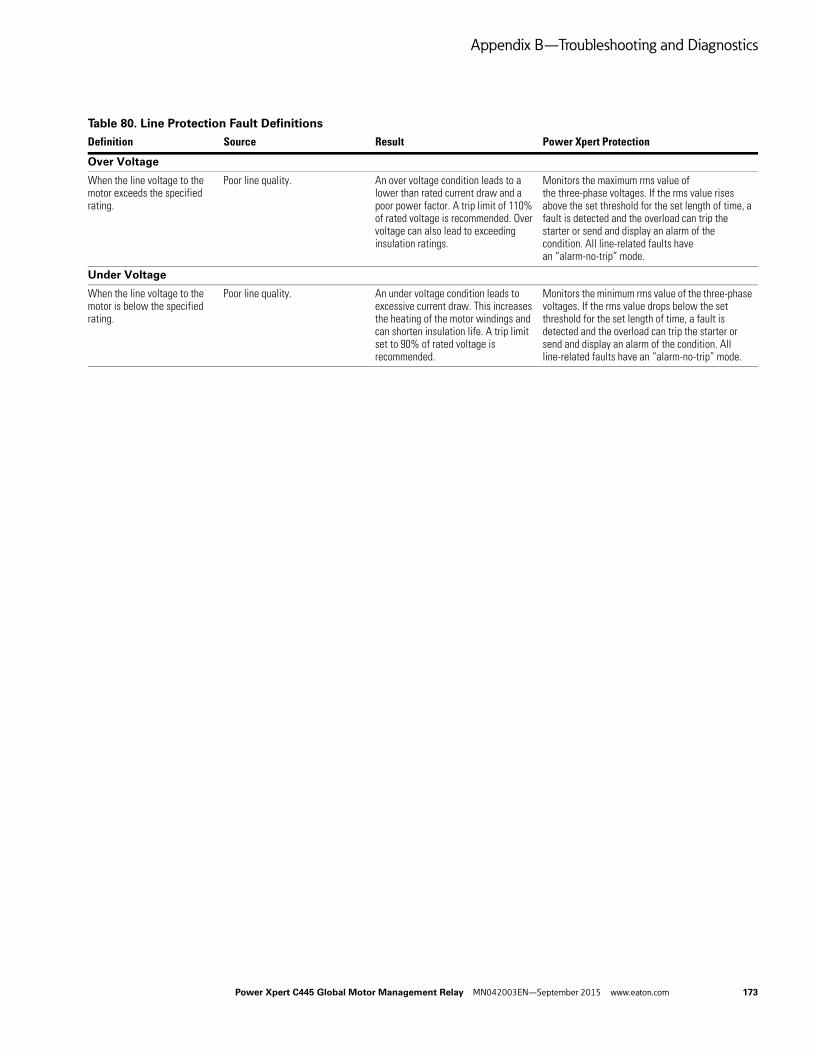
Appendix B—Troubleshooting and Diagnostics
Table 80. Line Protection Fault Definitions
Definition Source Result Power Xpert Protection
Over Voltage
When the line voltage to the motor exceeds the specified rating.
Poor line quality. An over voltage condition leads to a lower than rated current draw and a poor power factor. A trip limit of 110% of rated voltage is recommended. Over voltage can also lead to exceeding insulation ratings.
Monitors the maximum rms value of the three-phase voltages. If the rms value rises above the set threshold for the set length of time, a fault is detected and the overload can trip the starter or send and display an alarm of the condition. All line-related faults have an “alarm-no-trip” mode.
Under Voltage
When the line voltage to the motor is below the specified rating.
Poor line quality. An under voltage condition leads to excessive current draw. This increases the heating of the motor windings and can shorten insulation life. A trip limit set to 90% of rated voltage is recommended.
Monitors the minimum rms value of the three-phase voltages. If the rms value drops below the set threshold for the set length of time, a fault is detected and the overload can trip the starter or send and display an alarm of the condition. All line-related faults have an “alarm-no-trip” mode.
Power Xpert C445 Global Motor Management Relay MN042003EN—September 2015 www.eaton.com 173

Appendix C—Optional Communication Cards
Appendix C—Optional Communication Cards
Ethernet Card (C445CX-E)
Introduction
The C445 Ethernet option card (C445XC-E) supports both the Modbus TCP and EtherNet/IP protocols. This card contains two Ethernet ports but only one IP address. The ports act as a two-port Ethernet switch, allowing the user to optionally daisy chain modules together in a Ring or Linear network, instead of running each module back to a centralized Ethernet switch in a Star Network. Three supported Ethernet network topologies for the C445XC-E card are shown below.
Figure 154. C445 Ethernet Star Network Connection Example
Figure 155. C445 Ethernet Ring Network Connection Example
Figure 156. C445 Ethernet Linear Network Connection Example
Installing the Ethernet Communication Card
The Ethernet Communication Card is installed directly into the C445 Base Control Module. To install the card, follow the step by step directions:
1. Remove the blank cover
2. Locate the communication card slot
3. Plug the Ethernet communication card into location
Figure 157. Installing the Ethernet Communication Card
174 Power Xpert C445 Global Motor Management Relay MN042003EN—September 2015 www.eaton.com

Appendix C—Optional Communication Cards
Ethernet Communication Card and DIP Switches
When an optional Ethernet card is connected to a C445, the DIP switches on the Base Control Module are dedicated to determining the IP address of this card per the diagram below.
If the C445 Base Control Module also includes the optional RS-485 Modbus serial port, the node address and the data rate for this port must be configured using the Web Pages or the inControl Configuration Software.
DIP Switch settings on the C445 Base Control Module when an Ethernet Card is installed.
DIP Switch 10 is reserved for future use.
Figure 158. Base Control Module DIP Switches with Ethernet Card
Descriptions
When switch 9 is OFF:
Low Octet: DIP Switch numbers set low octet of static IP address 192.168.1.X where X is 0 – 253
Ethernet Port SettingThe lower 8 switches (1-7) are each given a value based on weighted binary. If the switch second from the top (9) is Off, the 8 lower switches are provided a value from the bottom up as follows: 1, 2, 4, 8, 16, 32, 64, 128. The switches are turned On when they are pushed to the right. Add the value of all switches that are On to determine the overall value. This value represents the low octet of the IP address 192.168.1.x. This is an easy way to configure the Ethernet Card to a known IP address so a computer can be configured to easily and quickly communicate with the C445 via Modbus TCP Ethernet with the inControl software tool. Then, using this tool, the C445 Ethernet Card may be configured with any static IP address. Information on how to go online with the C445 using the software tool and Modbus TCP may be found in the inControl software user manual. The following procedure indicates a procedure using the software tool to set a static IP address, subnet mask and gateway address for the C445 Ethernet Card.
1. Set DIP Switch 9 to OFF.
2. Set the bottom 2 DIP Switches (1-2) ON and leave the others OFF resulting in a value of 3 and an IP address of 192.168.1.3 assigned to the Ethernet Card.
3. Power cycle the C445 so the new DIP Switch settings will be used.
4. Using the inControl software, go online with the C445 via Modbus TCP and the Ethernet Card.
5. Under the Communications/Ethernet categories in the software tool, configure a static IP address, subnet mask and gateway address. These will not take effect until a soft reset is issued to the C445 or until it receives a power cycle.
6. Go offline with the C445 in the software tool.
7. Set the DIP Switches so only the following switches are ON: 2 and 9. The Ethernet Card will now be configured for “NV Static IP Address”.
8. Issue a soft reset or power cycle the C445. When it powers up the Ethernet Card will be configured with the static IP address, subnet mask and gateway address it was configured for with the inControl software tool.
9. This same process could be accomplished using the USB port or the RS-485 port with the inControl software tool.
Power Xpert C445 Global Motor Management Relay MN042003EN—September 2015 www.eaton.com 175

Appendix C—Optional Communication Cards
When switch 9 is ON and other DIP switches are:
0 – Static IP: hardcoded IP address of 192.168.1.254
1 – DHCP: Pulls IP address from DHCP server
2 – NV Static: Full address taken from device Non-Volatile Memory (static)
3 – NV DHCP: Addresses are taken from the DHCP server and assigned to device NV memory. To keep this address as static, power down the device and then change DIP Switch setting to 2 (NV Static) before re-powering the device
4 – Internal IP Address Allocation Method: Device disregards DIP Switch selections and IP configuration is done via inControl software by setting parameter “IP ADDRESS ALLOCATION METHOD.” The available settings for this parameter are the same as settings 0 through 3 available via DIP Switches. Setting 3 NV DHCP allows devices to get addresses from DHCP and assigns them to NV memory. Next, setting the parameter to 2 in the software before power cycle will allow devices to retain the last active IP addresses as static without having to physically change DIP Switches on each device.
The DIP Switches are used to configure the IP address for the Ethernet port. Even though there are two Ethernet ports on the Ethernet Option card, these ports act as a two port switch and both have the same IP address. This allows multiple C445 Ethernet Cards to be daisy-chained rather than each being connected to the same switch or switches. It also provides for the capability of connecting in a redundant ring topology when connected through switches that support this technology.
176 Power Xpert C445 Global Motor Management Relay MN042003EN—September 2015 www.eaton.com
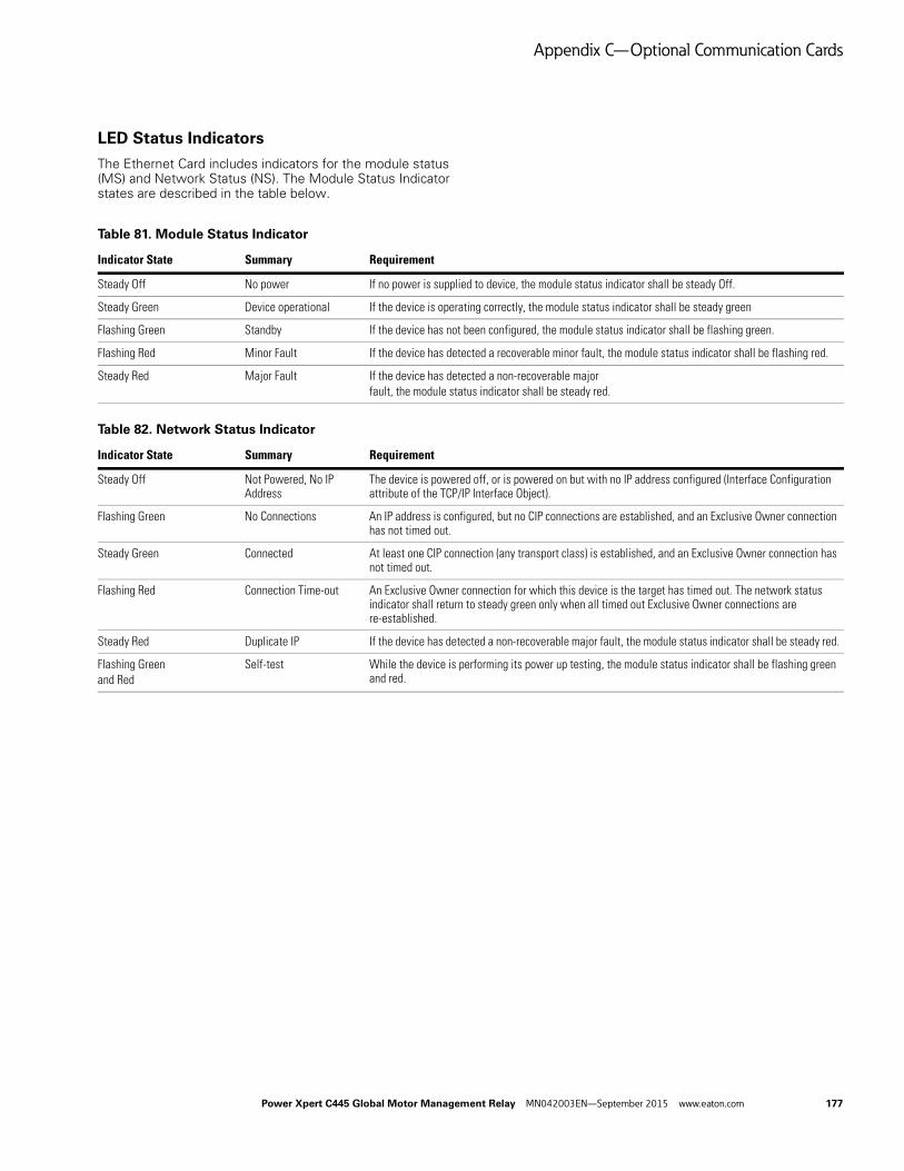
Appendix C—Optional Communication Cards
LED Status Indicators
The Ethernet Card includes indicators for the module status (MS) and Network Status (NS). The Module Status Indicator states are described in the table below.
Table 81. Module Status Indicator
Indicator State Summary Requirement
Steady Off No power If no power is supplied to device, the module status indicator shall be steady Off.
Steady Green Device operational If the device is operating correctly, the module status indicator shall be steady green
Flashing Green Standby If the device has not been configured, the module status indicator shall be flashing green.
Flashing Red Minor Fault If the device has detected a recoverable minor fault, the module status indicator shall be flashing red.
Steady Red Major Fault If the device has detected a non-recoverable majorfault, the module status indicator shall be steady red.
Table 82. Network Status Indicator
Indicator State Summary Requirement
Steady Off Not Powered, No IP Address
The device is powered off, or is powered on but with no IP address configured (Interface Configuration attribute of the TCP/IP Interface Object).
Flashing Green No Connections An IP address is configured, but no CIP connections are established, and an Exclusive Owner connection has not timed out.
Steady Green Connected At least one CIP connection (any transport class) is established, and an Exclusive Owner connection has not timed out.
Flashing Red Connection Time-out An Exclusive Owner connection for which this device is the target has timed out. The network status indicator shall return to steady green only when all timed out Exclusive Owner connections are re-established.
Steady Red Duplicate IP If the device has detected a non-recoverable major fault, the module status indicator shall be steady red.
Flashing Greenand Red
Self-test While the device is performing its power up testing, the module status indicator shall be flashing green and red.
Power Xpert C445 Global Motor Management Relay MN042003EN—September 2015 www.eaton.com 177

Appendix C—Optional Communication Cards
Ethernet LED Indications
Configuration Using a Web Browser
The Ethernet Card includes an embedded web page that provides the ability to monitor the status and set the configuration of the C445 Motor Management Relay System and the Ethernet Card. The Web Pages have been validated for use with Internet Explorer. To use the web page open your Internet Explorer browser and enter the IP address assigned to the Ethernet Card:
http:// IP Address
The web page provides five levels of authorization as shown in the chart below:
Note: In addition to the individual levels, a password
exemption setting is provided. This setting specifies a level that can be accessed without any password protection. The default value of the password
exemption is Super_User. All capabilities of the web page are accessible without a password prompt until the password exemption is changed to a lower level.
User names and passwords are case sensitive, and limited between 6~16 characters. For security reasons, it is recommended that the user change the default passwords and adjust the password exemption level to be lower than Super_User after configuration. It is also recommended that these changes be made within a local subnet.
Refer to System Configuration and Commissioning on Page 47 for a complete description and procedure on how to use the password feature for the Web Pages.
Table 83. Ethernet LED Description
LED Description
[1] Ethernet Link status Flashes with Ethernet message activity.
[2] Ethernet Link speed Displays the link speed:Amber LED on the Ethernet Jack is ON when link speed is 100 mbpsAmber LED on the Ethernet Jack is OFF when link speed is 10 mbps
Table 84. Five Levels Of Authorization
LevelDefault User Name
Default Password Description
Open <none> <none> Open access, has no password. Allows opening web page to be viewed, but no additional information is available
Read_Only readonly readonly Read_Only access allows parameters to be viewed, but no control or configuration
Control control control Control provides capabilities of Read_Only plus allows motor and discrete outputs to be turned on and off
Config configuration configuration Config provides capabilities of Control plus the ability to set configuration values
Super_User superuser superuser Super_User provides the capabilities of Config plus the ability to change user names and passwords
178 Power Xpert C445 Global Motor Management Relay MN042003EN—September 2015 www.eaton.com

Appendix C—Optional Communication Cards
Configuration Using an EDS File
The C445 has an EtherNet/IP EDS file available. It can be imported into any EtherNet/IP configuration tools that support EDS files. This EDS file may be downloaded from the Eaton website.
http://www.eaton.com
Configuring Using the inControl Software Tool
There is a Modbus TCP Ethernet DTM/Driver for the inControl software tool. This interface may be used to connect to the C445 Motor Management Relay via the C445 Ethernet Card. Refer to the inControl software tool user manual for additional information (publication MN040013EN.
EtherNet/IP Protocol
The C445 Ethernet Card can be connected to any EtherNet/IP network. It can be connected both as an Explicit Message server and as an Implicit (I/O) Message target.
The Implicit connections supported include:
● Exclusive Owner
● Listen Only
● Input Only
Table 85. EtherNet/IP Object Model for the C445 Motor Management Relay
No. Class Object No. of Instances Description
1 0x01 (1) Identity 1 Provides module identity object.
2 0x02 (2) Message Router 1 Internal object implemented per ODVA specification
3 0x04 (4) Assembly Object I/P:50, 51, 54, 100, 107, 110, 116, 121 O/P:2, 5,104, 105, 106 Dynamic I/P:150
Binds attributes from multiple objects for access with a single Implicit (I/O) connection.
4 0x06 (6) Connection Manager 1 Internal object supporting connection management. Implemented per ODVA specification
5 0x08 (8) Discrete Input Point 8 Status information for the discrete Inputs.
6 0x09 (9) Discrete Output Point 3 Status and control for the discrete Outputs.
7 0x29 (41) Control Supervisor 1 Motor control functions.
8 0x2C (44) Overload 1 Motor overload protection.
9 0x88 (136) System Component Definition 5 Vendor Specific Object.
10 0x93 (147) Voltage Object 1 Vendor Specific object for monitoring voltage.
11 0x96 (150) Dynamic Input Assembly Interface
1 An interface to insert the parameter in dynamic assembly instance number 150.
12 0xC7 (199) Test Only 1 Vendor Specific Object.
13 0x9B (155) Motor Info 1 Vendor Specific Object.
14 0x9F (159) Operation Mode 1 Vendor Specific Object.
15 0xA0 (160) Modbus 1 Vendor Specific Object.
16 0xA1(161) Motor Monitoring 1 Vendor Specific Object.
17 0xA2 (162) Motor Protection 1 Vendor Specific Object.
18 0xA5 (165) Snap Shot 1 Vendor Specific Object.
19 0xAA (170) Parameter Access 1 Vendor Specific Object.
20 0xB0 (176) RTC 1 Vendor Specific Object. Provides access to RTC
21 0xB1 (177) BCM 1 Vendor Specific Object.
22 0xB2 (178) BUI 1 Vendor Specific Object.
23 0xB3 (179) Option Card 1 Vendor Specific Object.
24 0xF4 (244) Port Object 1 The Port Object describes the communication interfaces that are present on the device and visible to CIP.
25 0xF5 (245) TCP/IP Interface 1 EtherNet/IP Specific object. Information about the TCP/IP Interface. Implemented per ODVA specification
26 0xF6 (246) Ethernet Link 2 EtherNet/IP Specific object. Ethernet link object for each of the 2 Ethernet ports on the device. Implemented per ODVA specification.
Power Xpert C445 Global Motor Management Relay MN042003EN—September 2015 www.eaton.com 179

Appendix C—Optional Communication Cards
Object Details
Table 86. Identity Object—Class 0x01 (1)
Class Services
ID Service
0x0E Get_Attribute_Single
0x01 Get_Attribute_All
Instance Services
ID Service
0x01 Get_Attributes_All
0x05 Reset Reset
Service data: 0 Soft Reset: Initializes adapter to the Power-up state.
Service data: 1 Factory Reset: Writes default values to all instance attributes and then saves all non-volatile attributes to NV memory and then performs the equivalent of a Reset(0).
0x0E Get_Attribute_Single
Class Attributes
Sr. No. ID Access Rule Data Type Description Remarks / Default Values
1 1 (0x1) Get UINT Revision 1
2 2 (0x2) Get UINT Max Instances 1
3 3 (0x3) Get UINT Number of instances 1
4 6 (0x6) Get UINT Maximum ID Class Attribute 7
5 7 (0x7) Get UINT Maximum ID Instance Attribute 7
Instance Attributes
Sr. No. ID Access Rule Data Type Description
1 1 (0x1) Get UINT Vendor ID 0x44 (68) (Eaton Vendor ID)
2 2 (0x2) Get UINT Device Type Motor Starter Profile: 0x16
3 3 (0x3) Get UINT Product Code 0x830A
4 4 (0x4) Get STRUCT of: Revision
USINT Major Revision 1
USINT Minor Revision 1
5 5 (0x5) Get WORD Status Status will be as per CIP Specification.
6 6 (0x6) Get UDINT Serial Number Unique number will be written during production.
7 7 (0x7) Get SHORT_STRING Product Name C445 EtherNet Communication Card
180 Power Xpert C445 Global Motor Management Relay MN042003EN—September 2015 www.eaton.com
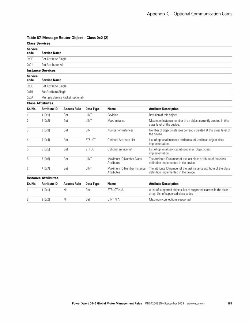
Appendix C—Optional Communication Cards
Table 87. Message Router Object—Class 0x2 (2)
Class Services
Service code Service Name
0x0E Get Attribute Single
0x01 Get Attributes All
Instance Services
Service code Service Name
0x0E Get Attribute Single
0x10 Set Attribute Single
0x0A Multiple Service Packet (optional)
Class Attributes
Sr. No. Attribute ID Access Rule Data Type Name Attribute Description
1 1 (0x1) Get UINT Revision Revision of this object
2 2 (0x2) Get UINT Max. Instance Maximum instance number of an object currently created in this class level of the device.
3 3 (0x3) Get UINT Number of Instances Number of object instances currently created at this class level of the device.
4 4 (0x4) Get STRUCT Optional Attribute List List of optional instance attributes utilized in an object class implementation.
5 5 (0x5) Get STRUCT Optional service list List of optional services utilized in an object class implementation.
6 6 (0x6) Get UINT Maximum ID Number Class Attributes
The attribute ID number of the last class attribute of the class definition implemented in the device.
7 7 (0x7) Get UINT Maximum ID Number Instance Attributes
The attribute ID number of the last instance attribute of the class definition implemented in the device.
Instance Attributes
Sr. No. Attribute ID Access Rule Data Type Name Attribute Description
1 1 (0x1) Nil Get STRUCT N.A. A list of supported objects. No.of supported classes in the class array. List of supported class codes
2 2 (0x2) Nil Get UINT N.A. Maximum connections supported
Power Xpert C445 Global Motor Management Relay MN042003EN—September 2015 www.eaton.com 181
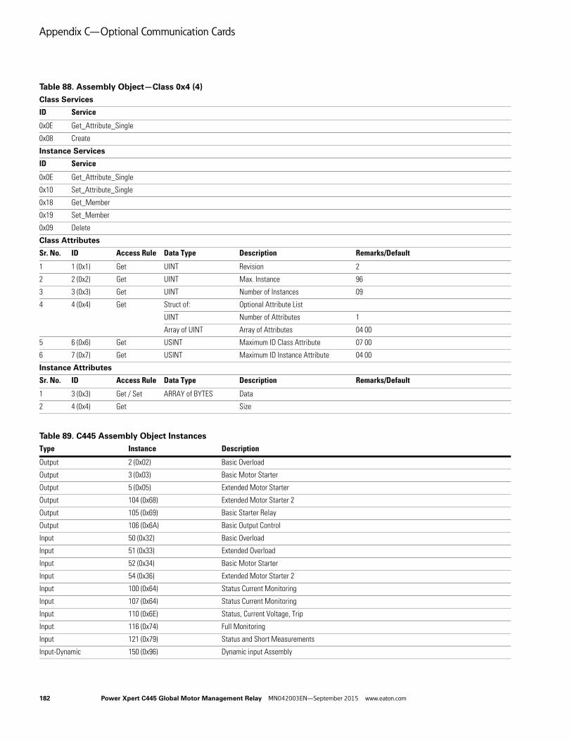
Appendix C—Optional Communication Cards
Table 88. Assembly Object—Class 0x4 (4)
Table 89. C445 Assembly Object Instances
Class Services
ID Service
0x0E Get_Attribute_Single
0x08 Create
Instance Services
ID Service
0x0E Get_Attribute_Single
0x10 Set_Attribute_Single
0x18 Get_Member
0x19 Set_Member
0x09 Delete
Class Attributes
Sr. No. ID Access Rule Data Type Description Remarks/Default
1 1 (0x1) Get UINT Revision 2
2 2 (0x2) Get UINT Max. Instance 96
3 3 (0x3) Get UINT Number of Instances 09
4 4 (0x4) Get Struct of: Optional Attribute List
UINT Number of Attributes 1
Array of UINT Array of Attributes 04 00
5 6 (0x6) Get USINT Maximum ID Class Attribute 07 00
6 7 (0x7) Get USINT Maximum ID Instance Attribute 04 00
Instance Attributes
Sr. No. ID Access Rule Data Type Description Remarks/Default
1 3 (0x3) Get / Set ARRAY of BYTES Data
2 4 (0x4) Get Size
Type Instance Description
Output 2 (0x02) Basic Overload
Output 3 (0x03) Basic Motor Starter
Output 5 (0x05) Extended Motor Starter
Output 104 (0x68) Extended Motor Starter 2
Output 105 (0x69) Basic Starter Relay
Output 106 (0x6A) Basic Output Control
Input 50 (0x32) Basic Overload
Input 51 (0x33) Extended Overload
Input 52 (0x34) Basic Motor Starter
Input 54 (0x36) Extended Motor Starter 2
Input 100 (0x64) Status Current Monitoring
Input 107 (0x64) Status Current Monitoring
Input 110 (0x6E) Status, Current Voltage, Trip
Input 116 (0x74) Full Monitoring
Input 121 (0x79) Status and Short Measurements
Input-Dynamic 150 (0x96) Dynamic input Assembly
182 Power Xpert C445 Global Motor Management Relay MN042003EN—September 2015 www.eaton.com

Appendix C—Optional Communication Cards
Output Instance 2: Basic Overload
Length = 1 Byte
Byte Bit 7 Bit 6 Bit 5 Bit 4 Bit 3 Bit 2 Bit 1 Bit 0
0 Reserved Reserved Reserved Reserved Reserved FaultReset Reserved Reserved
Output Instance 3: Basic Motor Starter
Length = 1 Byte
Byte Bit 7 Bit 6 Bit 5 Bit 4 Bit 3 Bit 2 Bit 1 Bit 0
0 Reserved Reserved Reserved Reserved Reserved FaultReset Reserved Run1
Output Instance 5: Extended Motor Starter
Length = 1 Byte
Byte Bit 7 Bit 6 Bit 5 Bit 4 Bit 3 Bit 2 Bit 1 Bit 0
0 Reserved Reserved Reserved Reserved Reserved FaultReset Run2 Run1
Input Instance 50: Basic Overload
Length = 1 Byte
Byte Bit 7 Bit 6 Bit 5 Bit 4 Bit 3 Bit 2 Bit 1 Bit 0
0 Reserved Reserved Reserved Reserved Reserved Reserved Reserved Fault/Trip
Input Instance 51: Extended Overload
Length = 1 Byte
Byte Bit 7 Bit 6 Bit 5 Bit 4 Bit 3 Bit 2 Bit 1 Bit 0
0 Reserved Reserved Reserved Reserved Reserved Reserved Warning Fault/trip
Input Instance 52: Basic Motor Starter
Length = 1 Byte
Byte Bit 7 Bit 6 Bit 5 Bit 4 Bit 3 Bit 2 Bit 1 Bit 0
0 Reserved Reserved Reserved Reserved Reserved Running 1 Reserved Faulted/Tripped
Input Instance 54: Extended Motor Starter 2
Length = 1 Byte
Byte Bit 7 Bit 6 Bit 5 Bit 4 Bit 3 Bit 2 Bit 1 Bit 0
0 Reserved Reserved Cntr lfrom Net Ready Running 2 Running 1 Warning Faulted/Trip
Power Xpert C445 Global Motor Management Relay MN042003EN—September 2015 www.eaton.com 183

Appendix C—Optional Communication Cards
Input Instance 100 (0x64): Status, Current
Length = 8 Bytes
ByteOffset
Size (bytes) Name Description
0 2 Device Status DCI_PACKED_C445_DEVICE_STATUS:Device Bit ArrayBit 0: Faulted/TrippedBit 1: WarningBit 2: Output #1Bit 3: Output #2Bit 4: Input #1Bit 5: Input #2Bit 6: Input #3Bit 7: Input #4Bit 8: Running1Bit 9: Running2Bit 10: Remote or CtrlFromNetBit 11: Output #3Bit 12: ReservedBit 13: InhibitedBit 14: ReadyBit 15: AtRef or Up-To-Speed
2 2 Current I1 DCI_MOTOR_I_A_SCALED:Phase A (L1) Motor Current Scaled. Scaled by parameter “I Scale Factor.”
4 2 Current I2 DCI_MOTOR_I_B_SCALED:Phase B (L2) Motor Current Scaled. Scaled by parameter “I Scale Factor.”
6 2 Current I3 DCI_MOTOR_I_C_SCALED:Phase C (L3) Motor Current Scaled. Scaled by parameter “I Scale Factor.”
Output Instance 104(0x68): Extended Motor Starter 2
Length = 2 Bytes
ByteOffset
Size (bytes) Name Description
0 2 Extended Motor Starter 2
Vendor specific Extended Motor starterBit 0 = Run1Bit 1 = Run2Bit 2 = ReservedBit3 = Fault ResetBit 4 to 15 = Reserved
184 Power Xpert C445 Global Motor Management Relay MN042003EN—September 2015 www.eaton.com

Appendix C—Optional Communication Cards
Output Instance 105(0x69): Basic Starter Relay
Length = 2 Bytes
ByteOffset
Size (bytes) Name Description
0 2 Basic Overloadw/Relay
Basic Overload with RelaysBit 0 = Output #1Bit 1 = Output #2Bit 2 = Output #3 (set)Bit 3 = Fault ResetBit 4 = Output #3 (reset)Bit 5 = Test TripBit 6 to 15 = reserved
Output Instance 106(0x6A): Basic Output Control
Length = 2 Bytes
ByteOffset
Size (bytes) Name Description
0 2 Basic Control Relay Basic Control Bits:(Byte1: DCI_NETCTRL_CONTROL_WORD)(Byte2: DCI_BCM_FIELD_OUTPUTS)Bit 0: Run1Bit 1: Run2Bit 2: ReservedBit 3: Fault ResetBit 4: Enable Control From Network ProtocolBit 5: Test TripBit 6: ReservedBit 7: ReservedBit 8: Output #1 (Conditional. Depends on profile selected)Bit 9: Output #2 (Conditional. Depends on profile selected)Bit 10: Output #3 (set) (Conditional. Depends on profile selected)Bit 11: Output #3 (reset) (Conditional. Depends on profile selected)Bits 12–15: Reserved
Power Xpert C445 Global Motor Management Relay MN042003EN—September 2015 www.eaton.com 185
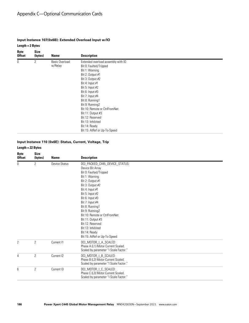
Appendix C—Optional Communication Cards
Input Instance 107(0x6B): Extended Overload Input w/IO
Length = 2 Bytes
ByteOffset
Size (bytes) Name Description
0 2 Basic Overload w/Relay
Extended overload assembly with IOBit 0: Faulted/TrippedBit 1: WarningBit 2: Output #1Bit 3: Output #2Bit 4: Input #1Bit 5: Input #2Bit 6: Input #3Bit 7: Input #4Bit 8: Running1Bit 9: Running2Bit 10: Remote or CtrlFromNetBit 11: Output #3Bit 12: ReservedBit 13: InhibitedBit 14: ReadyBit 15: AtRef or Up-To-Speed
Input Instance 110 (0x6E): Status, Current, Voltage, Trip
Length = 22 Bytes
ByteOffset
Size (bytes) Name Description
0 2 Device Status DCI_PACKED_C445_DEVICE_STATUS:Device Bit ArrayBit 0: Faulted/TrippedBit 1: WarningBit 2: Output #1Bit 3: Output #2Bit 4: Input #1Bit 5: Input #2Bit 6: Input #3Bit 7: Input #4Bit 8: Running1Bit 9: Running2Bit 10: Remote or CtrlFromNetBit 11: Output #3Bit 12: ReservedBit 13: InhibitedBit 14: ReadyBit 15: AtRef or Up-To-Speed
2 2 Current I1 DCI_MOTOR_I_A_SCALED:Phase A (L1) Motor Current Scaled. Scaled by parameter “I Scale Factor.”
4 2 Current I2 DCI_MOTOR_I_B_SCALED:Phase B (L2) Motor Current Scaled. Scaled by parameter “I Scale Factor.”
6 2 Current I3 DCI_MOTOR_I_C_SCALED:Phase C (L3) Motor Current Scaled. Scaled by parameter “I Scale Factor.”
186 Power Xpert C445 Global Motor Management Relay MN042003EN—September 2015 www.eaton.com

Appendix C—Optional Communication Cards
8 4 Trip Reason DCI_STATUS_TRIPPED_BITS0x0000 0001 - under voltage0x0000 0002 - over voltage0x0000 0004 - high resistance GF0x0000 0008 - residual GF0x0000 0010 - current phase loss0x0000 0020 - current unbalance0x0000 0040 - instantaneous over current0x0000 0080 - jam0x0000 0100 - PF deviation0x0000 0200 - voltage phase loss0x0000 0400 - voltage unbalance0x0000 0800 - freq deviation fast0x0000 1000 - freq deviation slow0x0000 2000 - under current0x0000 4000 - high power0x0000 8000 - low power0x0001 0000 - overload0x0002 0000 - stall0x0004 0000 - phase rotation0x0008 0000 - exceeds starts limit0x0010 0000 - initialization fault0x0020 0000 - NV memory fault0x0040 0000 - comm loss0x0080 0000 - comm msg error
12 2 Current Average DCI_MOTOR_I_AVE_SCALED:Average Motor Current Scaled.Scaled by parameter “I Scale Factor.”
14 2 VoltageL1-L2
DCI_LINE_V_LL_AB_RMS:Phase A RMS Voltage L1-L2 (V)
16 2 VoltageL2-L3
DCI_LINE_V_LL_BC_RMS:Phase B RMS Voltage L2-L3 (V)
18 2 VoltageL3-L1
DCI_LINE_V_LL_CA_RMS:Phase C RMS Voltage L3-L1 (V)
20 2 VoltageAverage
DCI_LINE_V_LN_AVE_RMS:Average RMS Voltage (V)
Input Instance 110 (0x6E): Status, Current, Voltage, Trip, continued
Length = 22 Bytes
ByteOffset
Size (bytes) Name Description
Power Xpert C445 Global Motor Management Relay MN042003EN—September 2015 www.eaton.com 187

Appendix C—Optional Communication Cards
Input Instance 116 (0x74): Full Monitoring
Length = 41 Bytes
ByteOffset
Size (bytes) Name Description
0 2 Device Status DCI_PACKED_C445_DEVICE_STATUS:Device Bit ArrayBit 0: Faulted/TrippedBit 1: WarningBit 2: Output #1Bit 3: Output #2Bit 4: Input #1Bit 5: Input #2Bit 6: Input #3Bit 7: Input #4Bit 8: Running1Bit 9: Running2Bit 10: Remote or CtrlFromNetBit 11: Output #3Bit 12: ReservedBit 13: InhibitedBit 14: ReadyBit 15: AtRef or Up-To-Speed
2 2 Current I1 DCI_MOTOR_I_A_SCALED:Phase A (L1) Motor Current Scaled. Scaled by parameter “I Scale Factor.”
4 2 Current I2 DCI_MOTOR_I_B_SCALED:Phase B (L2) Motor Current Scaled. Scaled by parameter “I Scale Factor.”
6 2 Current I3 DCI_MOTOR_I_C_SCALED:Phase C (L3) Motor Current Scaled. Scaled by parameter “I Scale Factor.”
8 2 Field inputs DCI_LOGIC_INPUT_STATE_BITFIELD:Digital Input Status.
10 2 Current Average DCI_MOTOR_I_AVE_SCALED:Average Motor Current Scaled.Scaled by parameter “I Scale Factor.”
12 2 VoltageL1-L2
DCI_LINE_V_LL_AB_RMS:Phase A RMS Voltage L1-L2 (V)
14 2 VoltageL2-L3
DCI_LINE_V_LL_BC_RMS:Phase B RMS Voltage L2-L3 (V)
16 2 VoltageL3-L1
DCI_LINE_V_LL_CA_RMS:Phase C RMS Voltage L3-L1 (V)
18 2 VoltageAverage
DCI_LINE_V_LN_AVE_RMS:Average RMS Voltage (V)
188 Power Xpert C445 Global Motor Management Relay MN042003EN—September 2015 www.eaton.com
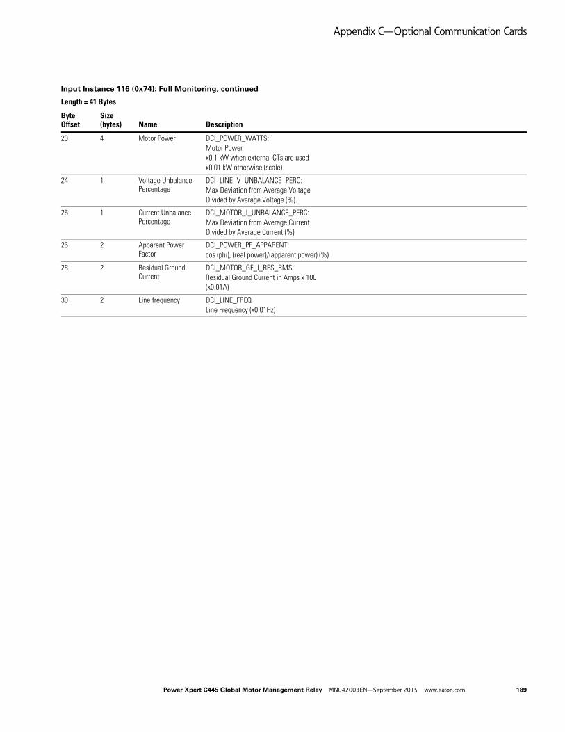
Appendix C—Optional Communication Cards
20 4 Motor Power DCI_POWER_WATTS:Motor Powerx0.1 kW when external CTs are usedx0.01 kW otherwise (scale)
24 1 Voltage Unbalance Percentage
DCI_LINE_V_UNBALANCE_PERC:Max Deviation from Average VoltageDivided by Average Voltage (%).
25 1 Current Unbalance Percentage
DCI_MOTOR_I_UNBALANCE_PERC:Max Deviation from Average CurrentDivided by Average Current (%)
26 2 Apparent Power Factor
DCI_POWER_PF_APPARENT:cos (phi), (real power)/(apparent power) (%)
28 2 Residual Ground Current
DCI_MOTOR_GF_I_RES_RMS:Residual Ground Current in Amps x 100(x0.01A)
30 2 Line frequency DCI_LINE_FREQLine Frequency (x0.01Hz)
Input Instance 116 (0x74): Full Monitoring, continued
Length = 41 Bytes
ByteOffset
Size (bytes) Name Description
Power Xpert C445 Global Motor Management Relay MN042003EN—September 2015 www.eaton.com 189
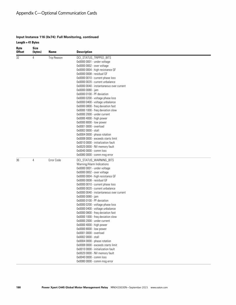
Appendix C—Optional Communication Cards
32 4 Trip Reason DCI_STATUS_TRIPPED_BITS0x0000 0001 - under voltage0x0000 0002 - over voltage0x0000 0004 - high resistance GF0x0000 0008 - residual GF0x0000 0010 - current phase loss0x0000 0020 - current unbalance0x0000 0040 - instantaneous over current0x0000 0080 - jam0x0000 0100 - PF deviation0x0000 0200 - voltage phase loss0x0000 0400 - voltage unbalance0x0000 0800 - freq deviation fast0x0000 1000 - freq deviation slow0x0000 2000 - under current0x0000 4000 - high power0x0000 8000 - low power0x0001 0000 - overload0x0002 0000 - stall0x0004 0000 - phase rotation0x0008 0000 - exceeds starts limit0x0010 0000 - initialization fault0x0020 0000 - NV memory fault0x0040 0000 - comm loss0x0080 0000 - comm msg error
36 4 Error Code DCI_STATUS_WARNING_BITSWarning/Alarm Indications0x0000 0001 - under voltage0x0000 0002 - over voltage0x0000 0004 - high resistance GF0x0000 0008 - residual GF0x0000 0010 - current phase loss0x0000 0020 - current unbalance0x0000 0040 - instantaneous over current0x0000 0080 - jam0x0000 0100 - PF deviation0x0000 0200 - voltage phase loss0x0000 0400 - voltage unbalance0x0000 0800 - freq deviation fast0x0000 1000 - freq deviation slow0x0000 2000 - under current0x0000 4000 - high power0x0000 8000 - low power0x0001 0000 - overload0x0002 0000 - stall0x0004 0000 - phase rotation0x0008 0000 - exceeds starts limit0x0010 0000 - initialization fault0x0020 0000 - NV memory fault0x0040 0000 - comm loss0x0080 0000 - comm msg error
Input Instance 116 (0x74): Full Monitoring, continued
Length = 41 Bytes
ByteOffset
Size (bytes) Name Description
190 Power Xpert C445 Global Motor Management Relay MN042003EN—September 2015 www.eaton.com

Appendix C—Optional Communication Cards
40 1 Thermal Pile Percentage
DCI_STATUS_OVLD_THERMAL_MEM_PERCENT:Thermal Capacity0% Cold Motor100% Will Cause an Overload Trip (%)
Input Instance 121 (0x79): Status And Short Measurements
Length = 10 Bytes
ByteOffset
Size (bytes) Name Description
0 2 Device Status DCI_PACKED_C445_DEVICE_STATUS:Device Bit ArrayBit 0: Faulted/TrippedBit 1: WarningBit 2: Output #1Bit 3: Output #2Bit 4: Input #1Bit 5: Input #2Bit 6: Input #3Bit 7: Input #4Bit 8: Running1Bit 9: Running2Bit 10: Remote or CtrlFromNetBit 11: Output #3Bit 12: ReservedBit 13: InhibitedBit 14: ReadyBit 15: AtRef or Up-To-Speed
Input Instance 116 (0x74): Full Monitoring, continued
Length = 41 Bytes
ByteOffset
Size (bytes) Name Description
Power Xpert C445 Global Motor Management Relay MN042003EN—September 2015 www.eaton.com 191
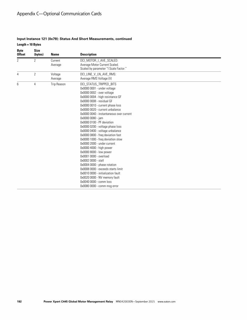
Appendix C—Optional Communication Cards
2 2 CurrentAverage
DCI_MOTOR_I_AVE_SCALED:Average Motor Current Scaled.Scaled by parameter “I Scale Factor.”
4 2 VoltageAverage
DCI_LINE_V_LN_AVE_RMS:Average RMS Voltage (V)
6 4 Trip Reason DCI_STATUS_TRIPPED_BITS0x0000 0001 - under voltage0x0000 0002 - over voltage0x0000 0004 - high resistance GF0x0000 0008 - residual GF0x0000 0010 - current phase loss0x0000 0020 - current unbalance0x0000 0040 - instantaneous over current0x0000 0080 - jam0x0000 0100 - PF deviation0x0000 0200 - voltage phase loss0x0000 0400 - voltage unbalance0x0000 0800 - freq deviation fast0x0000 1000 - freq deviation slow0x0000 2000 - under current0x0000 4000 - high power0x0000 8000 - low power0x0001 0000 - overload0x0002 0000 - stall0x0004 0000 - phase rotation0x0008 0000 - exceeds starts limit0x0010 0000 - initialization fault0x0020 0000 - NV memory fault0x0040 0000 - comm loss0x0080 0000 - comm msg error
Input Instance 121 (0x79): Status And Short Measurements, continued
Length = 10 Bytes
ByteOffset
Size (bytes) Name Description
192 Power Xpert C445 Global Motor Management Relay MN042003EN—September 2015 www.eaton.com
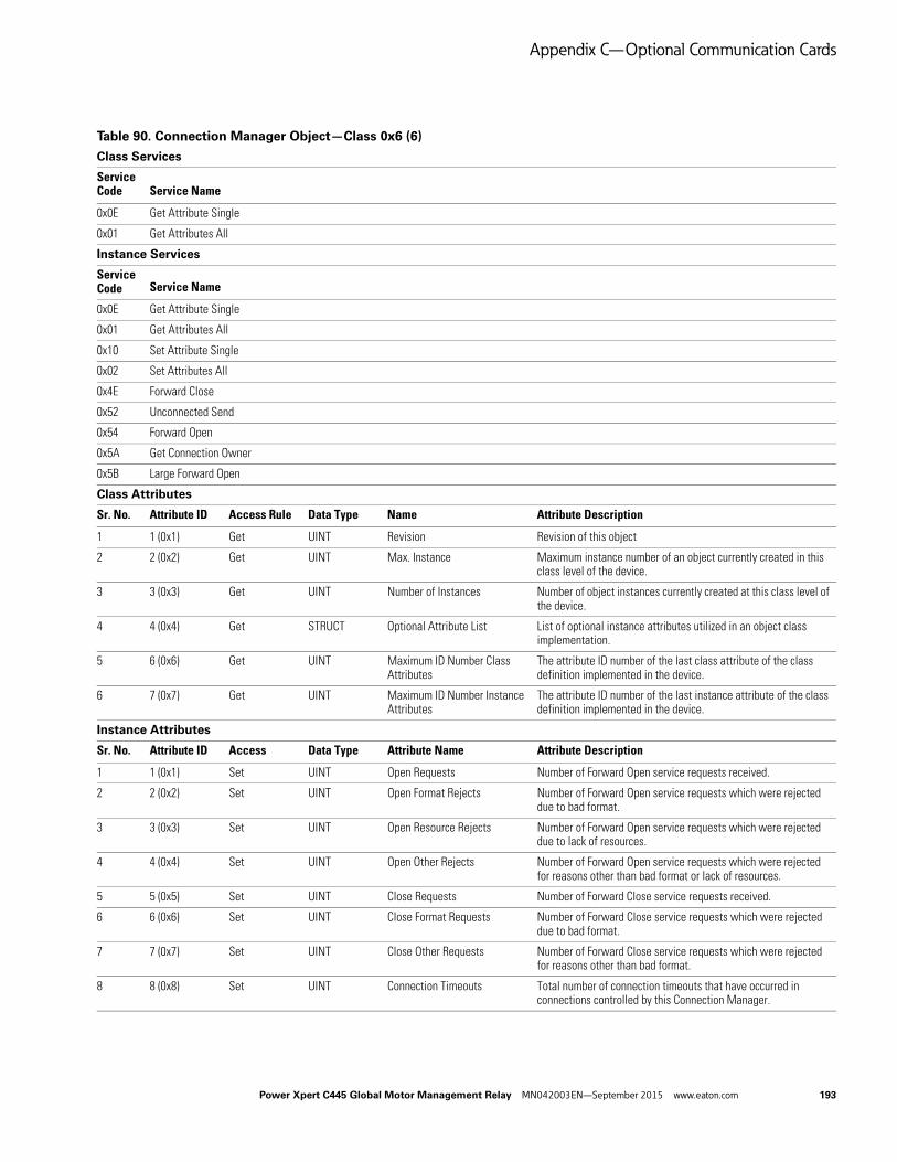
Appendix C—Optional Communication Cards
Table 90. Connection Manager Object—Class 0x6 (6)
Class Services
Service Code Service Name
0x0E Get Attribute Single
0x01 Get Attributes All
Instance Services
Service Code Service Name
0x0E Get Attribute Single
0x01 Get Attributes All
0x10 Set Attribute Single
0x02 Set Attributes All
0x4E Forward Close
0x52 Unconnected Send
0x54 Forward Open
0x5A Get Connection Owner
0x5B Large Forward Open
Class Attributes
Sr. No. Attribute ID Access Rule Data Type Name Attribute Description
1 1 (0x1) Get UINT Revision Revision of this object
2 2 (0x2) Get UINT Max. Instance Maximum instance number of an object currently created in this class level of the device.
3 3 (0x3) Get UINT Number of Instances Number of object instances currently created at this class level of the device.
4 4 (0x4) Get STRUCT Optional Attribute List List of optional instance attributes utilized in an object class implementation.
5 6 (0x6) Get UINT Maximum ID Number Class Attributes
The attribute ID number of the last class attribute of the class definition implemented in the device.
6 7 (0x7) Get UINT Maximum ID Number Instance Attributes
The attribute ID number of the last instance attribute of the class definition implemented in the device.
Instance Attributes
Sr. No. Attribute ID Access Data Type Attribute Name Attribute Description
1 1 (0x1) Set UINT Open Requests Number of Forward Open service requests received.
2 2 (0x2) Set UINT Open Format Rejects Number of Forward Open service requests which were rejected due to bad format.
3 3 (0x3) Set UINT Open Resource Rejects Number of Forward Open service requests which were rejected due to lack of resources.
4 4 (0x4) Set UINT Open Other Rejects Number of Forward Open service requests which were rejected for reasons other than bad format or lack of resources.
5 5 (0x5) Set UINT Close Requests Number of Forward Close service requests received.
6 6 (0x6) Set UINT Close Format Requests Number of Forward Close service requests which were rejected due to bad format.
7 7 (0x7) Set UINT Close Other Requests Number of Forward Close service requests which were rejected for reasons other than bad format.
8 8 (0x8) Set UINT Connection Timeouts Total number of connection timeouts that have occurred in connections controlled by this Connection Manager.
Power Xpert C445 Global Motor Management Relay MN042003EN—September 2015 www.eaton.com 193

Appendix C—Optional Communication Cards
Table 91. Discrete Input Object—Class 0x8 (8)
Class Services
Service code Service Name
0x0E Get Attribute Single
Instance Services
Service code Service Name
0x0E Get Attribute Single
0x10 Set Attribute Single
Class Attributes
Sr. No. Attribute ID Access Rule Data Type Name Attribute Description
1 1 (0x1) Get UINT Revision Revision of this object
2 2 (0x2) Get UINT Max. Instance Maximum instance number of an object currently created in this class level of the device.
3 3 (0x3) Get UINT Number of Instances Number of object instances currently created at this class level of the device.
Instance Attributes
Sr. No. Instance Attribute ID Access Data Type Attribute Name Attribute Description
1 1 (0x1), 3 (0x3) Get BOOL value ON/OFF Status of BCM Digital Inputs:0: OFF, 1: ONInstance 1- BCM Digital i/p-1
2 2(0x2) 3 (0x3) Get BOOL value ON/OFF Status of BCM Digital Inputs:0: OFF, 1: ONInstance 2-BCM Digital i/p-2
3 3(0x3) 3 (0x3) Get BOOL value ON/OFF Status of BCM Digital Inputs:0: OFF, 1: ONInstance 3-Digital i/p-3
4 4(0x4) 3 (0x3) Get BOOL value ON/OFF Status of BCM Digital Inputs:0: OFF, 1: ONInstance 4-BCM Digital i/p-4
5 5 (0x5), 3 (0x3) Get BOOL value ON/OFF Status of BUI Digital Inputs:0: OFF, 1: ONInstance 5-BUI Digital i/p-1
6 6(0x6) 3 (0x3) Get BOOL value ON/OFF Status of BUI Digital Inputs:0: OFF, 1: ONInstance 6-BUI Digital i/p-2
7 7(0x7) 3 (0x3) Get BOOL value ON/OFF Status of BUI Digital Inputs:0: OFF, 1: ONInstance 7-BUI Digital i/p-3
8 8(0x8) 3 (0x3) Get BOOL value ON/OFF Status of BUI Digital Inputs:0: OFF, 1: ONInstance 8-BUI Digital i/p-4
9 1 (0x1) 101 (0x65) Get/Set UINT Debounce BCM Digital i/p-1 debounce time. Applies to both raising & Falling edge. (mSec)
10 2(0x2) 101 (0x65) Get/Set UINT Debounce BCM Digital i/p-2 debounce time. Applies to both raising & Falling edge. (mSec)
11 3(0x3) 101 (0x65) Get/Set UINT Debounce BCM Digital i/p-3 debounce time. Applies to both raising & Falling edge. (mSec)
194 Power Xpert C445 Global Motor Management Relay MN042003EN—September 2015 www.eaton.com

Appendix C—Optional Communication Cards
Table 92. Discrete Output Object—Class 0x9 (9)
Instance Attributes
Sr. No. Instance Attribute ID Access Data Type Attribute Name Attribute Description
12 4(0x4) 101 (0x65) Get/Set UINT Debounce BCM Digital i/p-4 debounce time. Applies to both raising & Falling edge. (mSec)
13 5 (0x5), 101 (0x65) Get/Set UINT Debounce BUI Digital i/p-1 debounce time. Applies to both raising & Falling edge. (mSec)
14 6(0x6) 101 (0x65) Get/Set UINT Debounce BUI Digital i/p-2 debounce time. Applies to both raising & Falling edge. (mSec)
15 7(0x7) 101 (0x65) Get/Set UINT Debounce BUI Digital i/p-3 debounce time. Applies to both raising & Falling edge. (mSec)
16 8(0x8) 101 (0x65) Get/Set UINT Debounce BUI Digital i/p-4 debounce time. Applies to both raising & Falling edge. (mSec)
Class Services
Service code Service Name
0x0E Get Attribute Single
Instance Services
Service code Service Name
0x0E Get Attribute Single
0x10 Set Attribute Single
Class Attributes
Sr. No. Attribute ID Access Rule Data Type Name Attribute Description
1 1 (0x1) Get UINT Revision Revision of this object
2 2 (0x2) Get UINT Max. Instance Maximum instance number of an object currently created in this class level of the device.
3 3 (0x3) Get UINT Number of Instances
Number of object instances currently created at this class level of the device.
Instance Attributes
Sr. No. Instance Attribute ID Access Data Type Attribute Name Attribute Description
1 1 (0x1), 2 (0x2), 3 (0x3),4 (0x4)
3 (0x3) Set BOOL Logic output state bit field
ON/OFF Status of Digital Outputs. (BCM Field Output control)
2 1 (0x1), 2 (0x2), 3 (0x3)
5 (0x5) Set BOOL Fault Action Action taken on output’s value in Communication Fault state
3 1 (0x1), 2 (0x2), 3 (0x3)
6 (0x6) Set BOOL Fault Value User-defined value for use with Fault Action attribute
4 1 (0x1), 2 (0x2), 3 (0x3)
7 (0x7) Set BOOL Idle Action Action taken on output’s value in Communication Idle state
5 1 (0x1), 2 (0x2), 3 (0x3)
8 (0x8) Set BOOL Idle Value User-defined value for use with Idle Action attribute
Table 91. Discrete Input Object—Class 0x8 (8), continued
Power Xpert C445 Global Motor Management Relay MN042003EN—September 2015 www.eaton.com 195

Appendix C—Optional Communication Cards
Table 93. Control Supervisor Object—Class 0x29 (41)
Class Services
ID Service Requirements
0x0E Get Attribute Single
Instance Services
ID Service
0x0E Get_Attribute_Single
0x10 Set_Attribute_Single
0x05 Reset Service Type 0
Class Attributes
Sr. No. ID Access Rule Data Type Name Description Default Range
1 1 (0x1) Get UINT Revision 1 —
2 2 (0x2) Get UINT Max Instance 1 —
3 3 (0x3) Get UINT Number of Instances
1 —
Instance Attributes
Sr. No. ID Access Rule Data Type Description
1 3 (0x3) Set BOOL Run1 Run/Stop Event Matrix 0 0 – 1
2 4 (0x4) Set BOOL Run2 Run/Stop Event Matrix 0 0 – 1
3 5 (0x5) Set BOOL NetCtrl Requests Run/Stop control to be local or from network.0 = Local Control1 = Network Control
Note that the actual status of Run/Stop control is reflected in attribute 15, CtrlFromNet.
0 0 – 1
4 7 (0x7) Get BOOL Running1 1 = (Enabled and Run1) or (Stopping and Running1) or (Fault_Stop and Running1)0 = Other state
0 0 – 1
5 8 (0x8) Get BOOL Running2 1 = (Enabled and Run1) or (Stopping and Running1) or (Fault_Stop and Running1)0 = Other state
0 0 – 1
6 9 (0x9) Get BOOL Ready 1 = Ready or Enabled or Stopping0 = Other state
0 0 – 1
7 11 (0xB) Get BOOL Warning 1 = Warning (not latched)0 = No Warnings present
0 0-1
8 12 (0xC) Set BOOL FaultRst 0->1 = Fault Reset0 = No action
0 0 – 1
9 13 (0xD) Get UINT Fault Queue-1 A list of faults based on most recent. Duplicates are not allowed. They are sorted by event with the newest at the top of the queue.
10 15 (0xF) Get BOOL CtrlFromNet Status of Run/Stop control source.
0=Control is local1=Control is from network
0 0 – 1
11 17(0x11) Set BOOL CIP Force Fault (Need Dependent DCID in BCM)
0 ->1 = Force
196 Power Xpert C445 Global Motor Management Relay MN042003EN—September 2015 www.eaton.com
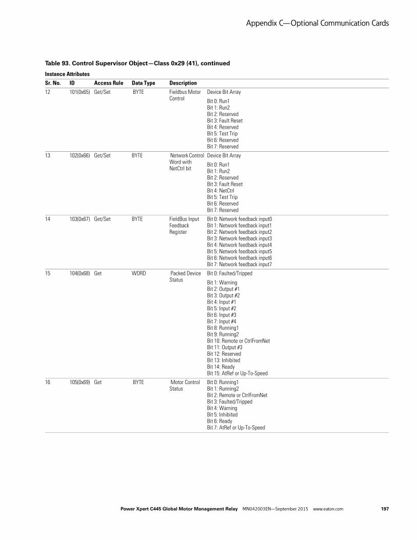
Appendix C—Optional Communication Cards
Instance Attributes
Sr. No. ID Access Rule Data Type Description
12 101(0x65) Get/Set BYTE Fieldbus Motor Control
Device Bit Array
Bit 0: Run1Bit 1: Run2Bit 2: ReservedBit 3: Fault ResetBit 4: Reserved Bit 5: Test TripBit 6: ReservedBit 7: Reserved
13 102(0x66) Get/Set BYTE Network Control Word with NetCtrl bit
Device Bit Array
Bit 0: Run1Bit 1: Run2Bit 2: ReservedBit 3: Fault ResetBit 4: NetCtrlBit 5: Test TripBit 6: ReservedBit 7: Reserved
14 103(0x67) Get/Set BYTE FieldBus Input Feedback Register
Bit 0: Network feedback input0Bit 1: Network feedback input1Bit 2: Network feedback input2Bit 3: Network feedback input3Bit 4: Network feedback input4Bit 5: Network feedback input5Bit 6: Network feedback input6Bit 7: Network feedback input7
15 104(0x68) Get WORD Packed Device Status
Bit 0: Faulted/Tripped
Bit 1: WarningBit 2: Output #1Bit 3: Output #2Bit 4: Input #1Bit 5: Input #2Bit 6: Input #3Bit 7: Input #4Bit 8: Running1Bit 9: Running2Bit 10: Remote or CtrlFromNetBit 11: Output #3Bit 12: ReservedBit 13: InhibitedBit 14: ReadyBit 15: AtRef or Up-To-Speed
16 105(0x69) Get BYTE Motor Control Status
Bit 0: Running1Bit 1: Running2Bit 2: Remote or CtrlFromNetBit 3: Faulted/TrippedBit 4: WarningBit 5: InhibitedBit 6: ReadyBit 7: AtRef or Up-To-Speed
Table 93. Control Supervisor Object—Class 0x29 (41), continued
Power Xpert C445 Global Motor Management Relay MN042003EN—September 2015 www.eaton.com 197

Appendix C—Optional Communication Cards
Instance Attributes
Sr. No. ID Access Rule Data Type Description
17 106(0x6A) Get Array of 4 Bytes Tripped Status Bits
Bit 0: UndervoltageBit 1: OvervoltageBit 2: External GFBit 3: Residual GFBit 4: Current phase lossBit 5: Current unbalanceBit 6: Instantaneous over currentBit 7: JamBit 8: PF deviationBit 9: Voltage phase lossBit 10: voltage unbalanceBit 11: Freq deviation fastBit 12: Freq deviation slowBit 13: Under currentBit 14: High powerBit 15: Low powerBit 16: ReservedBit 17: Exceeds starts limitBit 18: OverloadBit 19: StallBit 20: Phase rotationBit 21: PTCBit 22: Under voltage restartBit 23: Peak demand
18 107(0x6B) Get Array of 4 Bytes Warning Status Bits
Bit 0: UndervoltageBit 1: OvervoltageBit 2: External GFBit 3: Residual GFBit 4: Current phase lossBit 5: Current unbalanceBit 6: Instantaneous over currentBit 7: JamBit 8: PF deviationBit 9: Voltage phase lossBit 10: Voltage unbalanceBit 11: Freq deviation fastBit 12: Freq deviation slowBit 13: Under currentBit 14: High powerBit 15: Low powerBit 16: ReservedBit 17: Exceeds starts limitBit 18: OverloadBit 19: StallBit 20: Phase rotationBit 21: PTCBit 22: Under voltage restartBit 23: Peak demand
Table 93. Control Supervisor Object—Class 0x29 (41), continued
198 Power Xpert C445 Global Motor Management Relay MN042003EN—September 2015 www.eaton.com

Appendix C—Optional Communication Cards
Instance Attributes
Sr. No. ID Access Rule Data Type Description
19 108(0x6C) Get UINT Active Fault 0: No Faults1: Undervoltage2: Overvoltage3: External GF4: Residual GF5: Current phase loss6: Current unbalance7: Instantaneous over current8: Jam9: PF deviation10: Voltage phase loss11: Voltage unbalance12: Freq deviation fast13: Freq deviation slow14: Under current15: High power16: Low power17: Contactor failure18: Exceeds starts limit19: Overload20: Stall21: Phase rotation22: PTC - See PTC State for details23: Under voltage restart24: Measurement Module fault25: Communication loss on active fieldbus26: Measurement Module not available or comm loss with the module27: User Interface not available or comm loss with the module28: Test trip device fault29: Option card not available or comm loss with the module30: RTC Option board NV memory fail31: Currently connected User Interface does not match with what was connected before.32: Currently connected Measurement Module does not match with what was connected before.33: Currently connected Comm Card does not match with what was connected before500: Internal - Communication loss with Power Supply Board501: Internal - Power Supply Board is not responding to SPI502: Internal - Checksums in NV Memory (F-RAM) didn't match during read (neither pair)503: Internal - Checksums in NV Memory (F-RAM) didn't match during write (neither pair)504: Internal - Expected backup memory RTC module is missing505: Internal - Expected backup memory RTC module is mismatched with actual506: Internal - Backup Memory RTC module has NV fault.507: Internal - Serial flash memory fault in BCM508: Internal - Mapping Error
Table 93. Control Supervisor Object—Class 0x29 (41), continued
Power Xpert C445 Global Motor Management Relay MN042003EN—September 2015 www.eaton.com 199

Appendix C—Optional Communication Cards
Instance Attributes
Sr. No. ID Access Rule Data Type Description
20 109(0x6D) Get UINT Active Warning 0: No warnings1: Undervoltage2: Overvoltage3: External GF4: Residual GF5: Current phase loss6: Current unbalance7: Instantaneous over current8: Jam9: PF deviation10: Voltage phase loss11: Voltage unbalance12: Freq deviation fast13: Freq deviation slow14: Under current15: High power16: Low power17: Contactor failure18: Exceeds starts limit19: Overload20: Stall21: Phase rotation22: PTC - See PTC State for details23: Peak demand24: Measurement Module warning25: Real time clock default value loaded26: RTC battery voltage too low27: Base Control Module high temperature warning
21 110(0x6E) Get UINT Active Inhibit 0: No Inhibits1: Incorrect Configuration2: Soft reset required3: Backspin4: Undervoltage restart timer active5: Measurement Module inhibit6: Under voltage7: Voltage unbalance8: Starts per hour limit9: Over voltage inhibit
Table 93. Control Supervisor Object—Class 0x29 (41), continued
200 Power Xpert C445 Global Motor Management Relay MN042003EN—September 2015 www.eaton.com
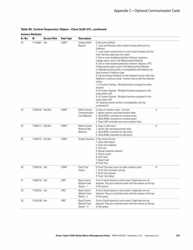
Appendix C—Optional Communication Cards
Instance Attributes
Sr. No. ID Access Rule Data Type Description
22 111(0x6F) Get USINT Config Inhibit Reason
0: No active inhibits1: Local and Remote motor control sources both point to Fieldwire2: Local motor control source is set to User Interface but the User Interface type does not match3: One or more enabled protection features requires a voltage option card in the Measurement Module4: One or more enabled protection features requires a PTC (Temperature) option card in the Measurement Module5: Selected starter profile is incompatible with fieldwire as local control or fieldwire type6: Cannot choose fieldwire as the feedback source when the fieldwire is used as a local / remote source with the selected starter7: UI Custom Overlay - Multiple buttons assigned to same function8: UI Custom Overlay - Multiple functions assigned to the same button LED9: UI Custom Overlay - Multiple functions assigned to the same status LED10: Selected starter profile is incompatible with the connected UI
23 112(0x70) Get/Set USINT Motor Control Communication Loss Behavior
0: Stop on comloss event - no fault1: Ignore comloss and keep present state2: Send RUN1 command on comloss event3: Send RUN2 command on comloss event4: Stop C445 controller and issue comloss fault
4
24 113(0x71) Get/Set USINT Motor Control Network Idle Behavior
0: Stop on idle event1: Ignore idle and keep present state2: Send RUN1 command on idle event3: Send RUN2 command on idle event
0
25 114(0x72) Get/Set USINT System Services 0: No Active Service1: Clear fault queue2: Clear trip snapshot3: Test trip4: Re-pair external modules5: Factory reset6: Soft reset7: Reset Fault8: Proof Test
26 115(0x73) Get USINT Proof Test Status
0: Proof Test was never run after a power cycle1: Proof Test currently running2: Proof Test passed3: Proof Test failed
0
27 116(0x74) Get UINT Base Control Module Fault Queue - 1
A list of faults based on most recent. Duplicates are not allowed. They are sorted by event with the newest at the top of the queue.
28 117(0x75) Get UINT Base Control Module Fault Queue - 2
A list of faults based on most recent. Duplicates are not allowed. They are sorted by event with the newest at the top of the queue.
29 118 (0x76) Get UINT Base Control Module Fault Queue – 3
A list of faults based on most recent. Duplicates are not allowed. They are sorted by event with the newest at the top of the queue.
Table 93. Control Supervisor Object—Class 0x29 (41), continued
Power Xpert C445 Global Motor Management Relay MN042003EN—September 2015 www.eaton.com 201
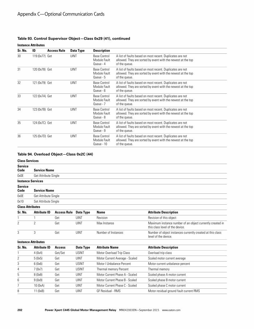
Appendix C—Optional Communication Cards
Instance Attributes
Sr. No. ID Access Rule Data Type Description
30 119 (0x77) Get UINT Base Control Module Fault Queue - 4
A list of faults based on most recent. Duplicates are not allowed. They are sorted by event with the newest at the top of the queue.
31 120 (0x78) Get UINT Base Control Module Fault Queue - 5
A list of faults based on most recent. Duplicates are not allowed. They are sorted by event with the newest at the top of the queue.
32 121 (0x79) Get UINT Base Control Module Fault Queue - 6
A list of faults based on most recent. Duplicates are not allowed. They are sorted by event with the newest at the top of the queue.
33 122 (0x7A) Get UINT Base Control Module Fault Queue - 7
A list of faults based on most recent. Duplicates are not allowed. They are sorted by event with the newest at the top of the queue.
34 123 (0x7B) Get UINT Base Control Module Fault Queue - 8
A list of faults based on most recent. Duplicates are not allowed. They are sorted by event with the newest at the top of the queue.
35 124 (0x7C) Get UINT Base Control Module Fault Queue - 9
A list of faults based on most recent. Duplicates are not allowed. They are sorted by event with the newest at the top of the queue.
36 125 (0x7D) Get UINT Base Control Module Fault Queue - 10
A list of faults based on most recent. Duplicates are not allowed. They are sorted by event with the newest at the top of the queue.
Table 94. Overload Object—Class 0x2C (44)
Class Services
Service Code Service Name
0x0E Get Attribute Single
Instance Services
Service Code Service Name
0x0E Get Attribute Single
0x10 Set Attribute Single
Class Attributes
Sr. No. Attribute ID Access Rule Data Type Name Attribute Description
1 1 Get UINT Revision Revision of this object
2 2 Get UINT Max Instance Maximum instance number of an object currently created in this class level of the device.
3 3 Get UINT Number of Instances Number of object instances currently created at this class level of the device.
Instance Attributes
Sr. No. Attribute ID Access Data Type Attribute Name Attribute Description
1 4 (0x4) Get/Set USINT Motor Overload Trip Class Overload trip class
2 5 (0x5) Get UINT Motor Current Average - Scaled Scaled motor current average
3 6 (0x6) Get USINT Motor I Unbalance Percent Motor current unbalance percent
4 7 (0x7) Get USINT Thermal memory Percent Thermal memory
5 8 (0x8) Get UINT Motor Current Phase A - Scaled Scaled phase A motor current
6 9 (0x9) Get UINT Motor Current Phase B - Scaled Scaled phase B motor current
7 10 (0xA) Get UINT Motor Current Phase C - Scaled Scaled phase C motor current
8 11 (0xB) Get UINT GF Residual - RMS Motor residual ground fault current RMS
Table 93. Control Supervisor Object—Class 0x29 (41), continued
202 Power Xpert C445 Global Motor Management Relay MN042003EN—September 2015 www.eaton.com

Appendix C—Optional Communication Cards
Instance Attributes
Sr. No. Attribute ID Access Data Type Attribute Name Attribute Description
9 101 (0x65) Get UINT Motor Overload Trip FLA Motor Overload Trip FLA
10 102 (0x66) Get/Set UINT Motor Overload Trip FLA Motor1 Motor Overload Trip FLA Motor1
11 103 (0x67) Get/Set UINT Motor Overload Trip FLA Motor2 Motor Overload Trip FLA Motor2
12 104 (0x68) Get UINT Motor Current Scale Factor Motor Current Scale Factor
13 105 (0x69) Get UINT Motor Current Average Percent FLA Motor Current Average Percent FLA
14 106 (0x6A) Get USINT Thermal capacity level remaining Thermal capacity level remaining
15 107 (0x6B) Get UINT Time for overload to reach reset threshold
Time for overload to reach reset threshold
16 108 (0x6C) Get UINT Time to Trip (overload) Time to Trip (overload)
17 109 (0x6D) Get/Set USINT Motor Overload Alarm Threshold Motor Overload Alarm Threshold
18 110 (0x6E) Get/Set USINT Thermal overload reset threshold. Level where reset is possible.
Thermal overload reset threshold. Level where reset is possible.
19 111 (0x6F) Get/Set UINT CT Ratio Active - Primary CT Ratio Active - Primary
20 112 (0x70) Get/Set UINT CT Ratio Active - Secondary CT Ratio Active - Secondary
21 113 (0x71) Get REAL Motor Current Average - Float Motor Current Average - Float
22 114 (0x72) Get REAL Motor Current Phase A - Float Motor Current Phase A - Float
23 115 (0x73) Get/ REAL Motor Current Phase B - Float Motor Current Phase B - Float
24 116 (0x74) Get REAL Motor Current Phase C - Float Motor Current Phase C - Float
25 117 (0x75) Get UINT Measurement Module FLA - Min Measurement Module FLA - Min
26 118 (0x76) Get UINT Measurement Module FLA - Max Measurement Module FLA - Max
Table 95. System Component Definition Object—Class 0x88 (136)
Class Services
Service Code
Service Name
0x0E Get Attribute Single
Instance Services
Service Code
Service Name
0x0E Get Attribute Single
0x10 Set Attribute Single
Class Attributes
Sr. No. Attribute ID Access Rule Data Type Name Attribute Description
1 1 Get UINT Revision Revision of this object
2 2 Get UINT Max Instance Maximum instance number of an object currently created in this class level of the device.
3 3 Get UINT Number of Instances Number of object instances currently created at this class level of the device.
Instance Attributes
Sr. No. Instance Attribute ID Access Data Type Attribute Name Attribute Description
1 1 (0x01) 1 (0x1) Get UINT BCM hardware rev BCM Product hardware revision numerical
2 1 (0x01) 2 (0x2) Get UINT BCM firmware rev BCM Firmware revision numerical
3 1 (0x01) 3 (0x3) Get UDINT BCM product Serial No. BCM Device Product Serial Number
4 1 (0x01) 4 (0x4) Get UINT BCM Product code BCM Product code.
5 1 (0x01) 5 (0x5) Get UINT BCM Product Sub code BCM Product Subcode.
Table 94. Overload Object—Class 0x2C (44), continued
Power Xpert C445 Global Motor Management Relay MN042003EN—September 2015 www.eaton.com 203

Appendix C—Optional Communication Cards
Instance Attributes
Sr. No. Instance Attribute ID Access Data Type Attribute Name Attribute Description
6 2 (0x02) 1 (0x1) Get UINT Power Board hardware rev Power Board Product hardware revision numerical
7 2 (0x02) 2 (0x2) Get UINT Power Board firmware rev Power Board Firmware revision numerical
8 2 (0x02) 3 (0x3) Get UDINT Power Board product Serial No. Power Board Device Product Serial Number
9 3 (0x03) 1 (0x1) Get UINT MM hardware rev MM Product hardware revision numerical
10 3 (0x03) 2 (0x2) Get UINT MM firmware rev MM Firmware revision numerical
11 3 (0x03) 3 (0x3) Get UDINT MM product Serial No. MM Device Product Serial Number
12 3 (0x03) 4 (0x4) Get UINT MM Product code MM Product code.
13 3 (0x03) 5 (0x5) Get UINT MM Product Sub code MM Product Subcode.
14 4 (0x04) 1 (0x1) Get UINT OPTION CARD hardware rev OPTION CARD Product hardware revision numerical
15 4 (0x04) 2 (0x2) Get Array of 2 UINT
OPTION CARD firmware rev OPTION CARD Firmware revision numerical
16 4 (0x04) 3 (0x3) Get UDINT OPTION CARD product Serial No. OPTION CARD Device Product Serial Number
17 4 (0x04) 4 (0x4) Get UINT OPTION CARD Product code OPTION CARD Product code.
18 4 (0x04) 5 (0x5) Get UINT OPTION CARD Product Sub code OPTION CARD Product Subcode.
19 5 (0x05) 2 (0x2) Get Array of 2 UINT
BUI firmware rev BUI Firmware revision numerical
20 5 (0x05) 3 (0x3) Get UDINT BUI product Serial No. BUI Device Product Serial Number
21 5 (0x05) 4 (0x4) Get UINT BUI Product code BUI Product code.
22 5 (0x05) 5 (0x5) Get UINT BUI Product Sub code BUI Product Subcode.
Table 96. Voltage Object—Class 0x93 (147)
Class Services
Service Code Service Name
0x0E Get Attribute Single
Instance Services
Service Code Service Name
0x0E Get Attribute Single
0x10 Set Attribute Single
Class Attributes
Sr. No. Attribute ID Access Rule Data Type Name Attribute Description
1 0x1 Get UINT Revision Revision of this object
2 0x2 Get UINT Max Instance Maximum instance number of an object currently created in this class level of the device.
3 0x3 Get UINT Number of Instances Number of object instances currently created at this class level of the device.
Instance Attributes
Sr. No. Attribute ID Access Data Type Attribute Name Attribute Description
1 1 (0x1) Get UINT Line Voltage LL Phases AB Supply Line-to-Line Voltage AB
2 2 (0x2) Get UINT Line Voltage LL Phases BC Supply Line-to-Line Voltage BC
3 3 (0x3) Get UINT Line Voltage LL Phases CA Supply Line-to-Line Voltage CA
4 4 (0x4) Get UIN T Line Voltage LL Average Supply Line-to-Line Voltage Average
5 5 (0x5) Get USINT Line V Unbalance Percent Supply Voltage Unbalance percentage
Table 95. System Component Definition Object—Class 0x88 (136), continued
204 Power Xpert C445 Global Motor Management Relay MN042003EN—September 2015 www.eaton.com

Appendix C—Optional Communication Cards
Instance Attributes
Sr. No. Attribute ID Access Data Type Attribute Name Attribute Description
6 6 (0x6) Get USINT Line Voltage Phase Order Supply frequency in centi-Hz
7 7 (0x7) Get/Set UINT PT Ratio (only available with external PT) - Primary
PT Ratio (only available with external PT) - Primary
8 8 (0x8) Get UINT Line Frequency - Scaled Line Frequency - Scaled
9 9 (0x9) Get/Set UINT PT Ratio (only available with external PT) - Secondary
PT Ratio (only available with external PT) - Secondary
10 10 (0xA) Get UINT Measurement Module Voltage Scale Factor
Measurement Module Voltage Scale Factor
11 11 (0xB) Get/Set USINT Protection UnderVoltage Trip Level
Protection UnderVoltage Trip Level
12 12 (0xC) Get/Set UINT Protection UnderVoltage Trip Debounce
Protection UnderVoltage Trip Debounce
13 13 (0xD) Get/Set USINT Protection UnderVoltage Alarm Level
Protection UnderVoltage Alarm Level
14 14 (0xE) Get/Set UINT Protection UnderVoltage Start Delay
Protection UnderVoltage Start Delay
15 15 (0xF) Get/Set UINT Protection OverVoltage Trip Level Protection OverVoltage Trip Level
16 16 (0x10) Get/Set UINT Protection OverVoltage Trip Debounce
Protection OverVoltage Trip Debounce
17 17 (0x11) Get/Set UINT Protection OverVoltage Alarm Level
Protection OverVoltage Alarm Level
18 18 (0x12) Get/Set USINT Protection V Unbalance Trip Percent Level
Protection V Unbalance Trip Percent Level
19 19 (0x13) Get/Set UINT Protection V Unbalance Trip Debounce Time
Protection V Unbalance Trip Debounce Time
20 20 (0x14) Get/Set USINT Protection V Unbalance Alarm Percent Level
Protection V Unbalance Alarm Percent Level
21 21 (0x15) Get USINT V Phase Loss Trip Level in percent V Phase Loss Trip Level in percent
22 22 (0x16) Get UINT V Phase Loss Debounce V Phase Loss Debounce
23 23 (0x17) Get/Set BOOL Protection start inhibit enable Protection start inhibit enable
24 24 (0x18) Get/Set USINT Undervoltage start inhibit threshold
Undervoltage start inhibit threshold
25 25 (0x19) Get/Set USINT Voltage Imbalance start inhibit threshold
Voltage Imbalance start inhibit threshold
26 26 (0x1A) Get/Set USINT Over Voltage start inhibit threshold
Over Voltage start inhibit threshold
27 27 (0x1B) Get/Set USINT Protection Under Voltage Restart Fault Level (Percent)
Protection Under Voltage Restart Fault Level (Percent)
28 28 (0x1C) Get/Set USINT Protection Under Voltage Restart Restoration Level (Percent)
Protection Under Voltage Restart Restoration Level (Percent)
29 29 (0x1D) Get/Set UINT Undervoltage restart max time for immediate restart
Undervoltage restart max time for immediate restart
30 30 (0x1E) Get/Set UDINT Undervoltage restart delay short Undervoltage restart delay short
31 31 (0x1F) Get/Set UDINT Undervoltage restart max time for delayed restart short
Undervoltage restart max time for delayed restart short
32 32 (0x20) Get/Set UINT Undervoltage restart delay long Undervoltage restart delay long
33 33 (0x21) Get/Set UINT Undervoltage restart max time for delayed restart long
Undervoltage restart max time for delayed restart long
Table 96. Voltage Object—Class 0x93 (147), continued
Power Xpert C445 Global Motor Management Relay MN042003EN—September 2015 www.eaton.com 205

Appendix C—Optional Communication Cards
Table 97. Dynamic input Assembly Interface Object—Class 0x96 (150)
Class Services
Service code Service Name
0x0E Get Attribute Single
Instance Services
Service code Service Name
0x0E Get Attribute Single
0x10 Set Attribute Single
Class Attributes
Sr. No. Attribute ID Access Rule Data Type Name Attribute Description
1 0x1 Get UINT Revision Revision of this object
2 0x2 Get UINT Max. Instance Maximum instance number of an object currently created in this class level of the device.
3 0x3 Get UINT Number of Instances Number of object instances currently created at this class level of the device.
Instance Attributes
Sr. No. Attribute ID Access Data Type Attribute Name Attribute Description Default
1 1 (0x1) Get/Set UINT Dynamic Assembly Interface-Index-1 An interface to insert the parameter in dynamic assembly instance number 150, Index-1.
1
2 2 (0x2) Get/Set UINT Dynamic Assembly Interface-Index-2 An interface to insert the parameter in dynamic assembly instance number 150, Index-2.
18
3 3 (0x3) Get/Set UINT Dynamic Assembly Interface-Index-3 An interface to insert the parameter in dynamic assembly instance number 150, Index-3.
2
4 4 (0x4) Get/Set UINT Dynamic Assembly Interface-Index-4 An interface to insert the parameter in dynamic assembly instance number 150, Index-4.
3
5 5 (0x5) Get/Set USINT Dynamic Assembly Interface-Index-5 An interface to insert the parameter in dynamic assembly instance number 150, Index-5.
4
6 6 (0x6) Get/Set UINT Dynamic Assembly Interface-Index-6 An interface to insert the parameter in dynamic assembly instance number 150, Index-6.
6
7 7 (0x7) Get/Set USINT Dynamic Assembly Interface-Index-7 An interface to insert the parameter in dynamic assembly instance number 150, Index-7.
7
8 8 (0x8) Get/Set USINT Dynamic Assembly Interface-Index-8 An interface to insert the parameter in dynamic assembly instance number 150, Index-8.
8
206 Power Xpert C445 Global Motor Management Relay MN042003EN—September 2015 www.eaton.com

Appendix C—Optional Communication Cards
C445 supports following parameters as a member of dynamic input assembly instance.
Table 98. Dynamic Input Assembly Instance Parameters
Value Parameter Name Related DCID
0 Assembly Terminator DCI_D_IN_ASM_TERMINATOR_DCID
1 Packed Device status (See Control Supervisor Object) DCI_PACKED_C445_DEVICE_STATUS_DCID
2 Motor Current Phase A - Scaled DCI_MOTOR_I_A_SCALED_DCID
3 Motor Current Phase B - Scaled DCI_MOTOR_I_B_SCALED_DCID
4 Motor Current Phase C - Scaled DCI_MOTOR_I_C_SCALED_DCID
5 Motor Current Average - Scaled DCI_MOTOR_I_AVE_SCALED_DCID
6 Line Voltage LL Phases AB DCI_LINE_V_LL_AB_RMS_DCID
7 Line Voltage LL Phases BC DCI_LINE_V_LL_BC_RMS_DCID
8 Line Voltage LL Phases CA DCI_LINE_V_LL_CA_RMS_DCID
9 Line Voltage LL Average DCI_LINE_V_LL_AVE_RMS_DCID
10 Total Watts for all three phases DCI_POWER_WATTS_DCID
11 Line V Unbalance Percent DCI_LINE_V_UNBALANCE_PERC_DCID
12 Motor Current Average Percent FLA DCI_MOTOR_I_AVE_PERCENT_FLA_DCID
13 Apparent Power Factor DCI_POWER_PF_APPARENT_DCID
14 GF High Resistance - RMS DCI_MOTOR_GF_I_HR_RMS_DCID
15 Line Frequency - Scaled DCI_LINE_FREQ_DCID
16 Thermal memory Percent DCI_STATUS_OVLD_THERMAL_MEM_PERCENT_DCID
17 Signal Status Bits DCI_STATUS_SIGNAL_BITS_DCID
18 Warning Status Bits DCI_STATUS_WARNING_BITS_DCID
19 BCM Digital Input Status DCI_LOGIC_INPUT_STATE_BITFIELD_DCID
Table 99. Test Only Object—Class 0xC7 (199)
Class Services
Service Code Service Name
0x0E Get Attribute Single
Instance Services
Service Code Service Name
0x0E Get Attribute Single
0x10 Set Attribute Single
Class Attributes
Sr. No. Attribute ID Access Rule Data Type Name Attribute Description
1 1 (0x1) Get UINT Revision Revision of this object
2 2 (0x2) Get UINT Max Instance Maximum instance number of an object currently created in this class level of the device.
3 3 (0x3) Get UINT Number of Instances Number of object instances currently created at this class level of the device.
Power Xpert C445 Global Motor Management Relay MN042003EN—September 2015 www.eaton.com 207

Appendix C—Optional Communication Cards
Instance Attributes
Sr. No. Attribute ID Access Data Type Attribute Name Attribute Description
1 1 (0x1) Get/Set USINT force overload perc Force Overload Perc
2 2 (0x2) Get UINT idle loop time ave Amount of time it takes to run through one complete run of all processes inside the idle task. The time to run all items in the idle task loop.
3 3 (0x3) Get/Set UINT idle loop time max Max amount of time it takes to run through one complete run of all processes inside the idle task. The max time to run all items in the idle task loop. This value can be reset by writing a zero into the location.
4 4 (0x4) Get/Set UINT idle loop time min Min amount of time it takes to run through one complete run of all processes inside the idle task. The min time to run all items in the idle task loop. This value can be reset.
5 5 (0x5) Get/Set USINT bcm heap used max perc BCM Maximum heap usage percent (Resettable)
6 6 (0x6) Get USINT bcm heap used perc BCM Current heap usage percent
7 7 (0x7) Get USINT bcm cstack usage percent BCM Cstack Usage percent
8 8 (0x8) Get/Set UINT num option card comm crc errors Provides the number of crc errors that have occurred between the option card and the BCM
9 9 (0x9) Get/Set USINT mm sim enable Simulation enable
10 10 (0xA) Get/Set USINT mm sim freq Simulation frequency
11 11 (0xB) Get/Set UINT mm sim i a Simulation Current A
12 12 (0xC) Get/Set UINT mm sim i b Simulation Current B
13 13 (0xD) Get/Set UINT mm sim i c Simulation Current C
14 14 (0xE) Get/Set UINT mm sim v a Simulation VAN
15 15 (0xF) Get/Set UINT mm sim v b Simulation VBN
16 16 (0x10) Get/Set UINT mm sim v c Simulation VCN
17 17 (0x11) Get/Set UINT mm sim phi i1 MM simulator - IA angle
18 18 (0x12) Get/Set UINT mm sim phi i2 MM simulator - IB angle
19 19 (0x13) Get/Set UINT mm sim phi i3 MM simulator - IC angle
20 20 (0x14) Get/Set UINT mm sim phi v1 MM simulator - VAN angle
21 21 (0x15) Get/Set UINT mm sim phi v2 MM simulator - VBN angle
22 22 (0x16) Get/Set UINT mm sim phi v3 MM simulator - VCN angle
23 23 (0x17) Get/Set UINT mm sim vn simulator - VN RMS
24 24 (0x18) Get/Set UINT mm sim phi vn simulator - VN angle
25 25 (0x19) Get/Set UINT mm med filt type RMS filter type bits 0-3: V&I bits 4-7: power bits 8-11: ground fault 0 = off, 1 = on, 2 = cal
26 26 (0x1A) Get/Set USINT bui heap used max perc BUI Maximum heap usage percent
27 27 (0x1B) Get USINT bui heap used perc BUI Current heap usage percent
28 28 (0x1C) Get USINT bui cstack usage percent BUI Cstack Usage percent
29 29 (0x1D) Get/Set USINT bui0 led brightness bank 0 LED Brightness Configuration Bank 0
30 30 (0x1E) Get/Set USINT bui0 led brightness bank 1 LED Brightness Configuration Bank 1
31 31 (0x1F) Get/Set USINT bui0 led brightness bank 2 LED Brightness Configuration Bank 2
32 32 (0x20) Get/Set USINT bui0 led brightness bank 3 LED Brightness Configuration Bank 3
33 33 (0x21) Get/Set USINT bui0 led ctrl 0 LED Control 0 - ON/OFF, color bitfield
34 34 (0x22) Get/Set USINT bui0 led ctrl 1 LED Control 1 - ON/OFF, color bitfield
35 35 (0x23) Get/Set USINT bui0 led ctrl 2 LED Control 2 - ON/OFF, color bitfield
36 36 (0x24) Get/Set USINT bui0 led ctrl 3 LED Control 3 - ON/OFF, color bitfield
37 37 (0x25) Get/Set USINT bui0 led ctrl 4 LED Control 4 - ON/OFF, color bitfield
38 38 (0x26) Get/Set USINT bui0 led ctrl 5 LED Control 5 - ON/OFF, color bitfield
Table 99. Test Only Object—Class 0xC7 (199), continued
208 Power Xpert C445 Global Motor Management Relay MN042003EN—September 2015 www.eaton.com

Appendix C—Optional Communication Cards
Instance Attributes
Sr. No. Attribute ID Access Data Type Attribute Name Attribute Description
39 39 (0x27) Get/Set USINT bui0 led ctrl 6 LED Control 6 - ON/OFF, color bitfield
40 40 (0x28) Get/Set USINT bui0 led ctrl 7 LED Control 7 - ON/OFF, color bitfield
41 41 (0x29) Get/Set USINT bui0 led ctrl 8 LED Control 8 - ON/OFF, color bitfield
42 42 (0x2A) Get/Set USINT bui0 led ctrl 9 LED Control 9 - ON/OFF, color bitfield
43 43 (0x2B) Get UINT bcm firmware crc val BCM Firmware CRC
44 44 (0x2C) Get UINT ps firmware crc val —
45 45 (0x2D) Get UINT mm firmware crc val —
46 46 (0x2E) Get UINT option card firmware crc val —
47 47 (0x2F) Get DINT power energy real frac Real Energy Fractional
48 48 (0x30) Get/Set DINT power energy real reset frac Real Energy - Fractional (Resettable)
49 49 (0x31) Get DINT power energy reactive frac Reactive Energy Fractional
50 50 (0x32) Get/Set DINT power energy reactive reset frac Reactive Energy - Fractional (Resettable)
51 51 (0x33) Get DINT power energy apparent frac Apparent Energy Fractional
52 52 (0x34) Get/Set DINT power energy apparent reset frac Apparent Energy - Fractional (Resettable)
53 53 (0x35) Get/Set USINT KSZ’s register no. which want to Read KSZ’s register no. which want to Read
54 54 (0x36) Get USINT Reading of KSZ’s register Reading of KSZ’s register
55 55 (0x37) Get/Set BOOL Enable Read Access to KSZ’s Register Enable Read Access to KSZ’s Register
56 56 (0x38) Get/Set USINT KSZ’s register no. which want to write KSZ’s register no. which want to write
57 57 (0x39) Get/Set USINT Value which want to write into KSZ’s register
Value which want to write into KSZ’s register
58 58 (0x3A) Get/Set BOOL Enable Write Access to KSZ’s Register Enable Write Access to KSZ’s Register
Table 100. Motor Info Object—Class 0x9B (155)
Class Services
Service Code Service Name
0x0E Get Attribute Single
Instance Services
Service Code Service Name
0x0E Get Attribute Single
0x10 Set Attribute Single
Class Attributes
Sr. No. Attribute ID Access Rule Data Type Name Attribute Description
1 1 (0x1) Get UINT Revision Revision of this object
2 2 (0x2) Get UINT Max Instance Maximum instance number of an object currently created in this class level of the device.
3 3 (0x3) Get UINT Number of Instances Number of object instances currently created at this class level of the device.
Instance Attributes
Sr. No. Attribute ID Access Data Type Attribute Name Attribute Description
1 1 (0x1) Get/Set UINT Rated Voltage Motor rated voltage
2 2 (0x2) Get/Set UDINT Motor Rated Hp Motor1 (Scaled by 100) Motor Rated Hp Run1
3 3 (0x3) Get/Set UDINT Motor Rated Hp Motor2 (Scaled by 100) Motor Rated Hp Run2
4 4 (0x4) Get/Set UDINT Motor Rated Watts Motor1 Motor Rated Watts Run1
Table 99. Test Only Object—Class 0xC7 (199), continued
Power Xpert C445 Global Motor Management Relay MN042003EN—September 2015 www.eaton.com 209

Appendix C—Optional Communication Cards
Instance Attributes
Sr. No. Attribute ID Access Data Type Attribute Name Attribute Description
5 5 (0x5) Get/Set UDINT Motor Rated Watts Motor2 Motor Rated Watts Run2
6 6 (0x6) Get/Set UINT Motor Rated Speed Motor1 Motor Rated Speed RPM Run1
7 7 (0x7) Get/Set UINT Motor Rated Speed Motor2 Motor Rated Speed RPM Run2
8 8 (0x8) Get/Set UINT Rated Freq Motor rated frequency in Hz
9 9 (0x9) Get/Set UINT Motor Rated Efficiency Motor rated efficiency in percentage
10 10(0xA) Get/Set INT Motor Rated PF (scaled by 100) Motor rated power factor in percentage
11 11 (0xB) Get/Set USINT Motor Rated Service Factor Motor Rated Service Factor
12 12 (0xC) Get/Set UINT Motor Rated Stator Resistance (Scaled x1000)
Motor Rated Stator Resistance (Scaled x1000)
13 13 (0xD) Get UDINT Motor Rated Hp Active (Scaled by 100) Motor Rated Hp Active
14 14 (0xE) Get UINT Motor Rated Speed Active Motor Rated Speed RPM active
15 15 (0xF) Get UDINT Motor Rated Watts Active Motor Rated Watts Active
Table 101. Operation Mode Object—Class 0x9F (159)
Class Services
Service Code Service Name
0x0E Get Attribute Single
Instance Services
Service Code Service Name
0x0E Get Attribute Single
0x10 Set Attribute Single
Class Attributes
Sr. No. Attribute ID Access Rule Data Type Name Attribute Description
1 1 (0x1) Get UINT Revision Revision of this object
2 2 (0x2) Get UINT Max Instance Maximum instance number of an object currently created in this class level of the device.
3 3 (0x3) Get UINT Number of Instances Number of object instances currently created at this class level of the device.
Instance Attributes
Sr. No. Attribute ID Access Data Type Attribute Name Attribute Description
1 1 (0x1) Get/Set USINT Used to select the desired control profile (soft reset required)
Used to select the desired control profile (soft reset required)
2 2 (0x2) Get/Set UINT Delay before control fault is issued (in 10ms)
Delay before control fault is issued (in 10ms)
3 3 (0x3) Get/Set UINT Interlocking time between contactor direction changes (in 0.01sec)
Interlocking time between contactor direction changes (in 0.01sec)
4 4 (0x4) Get/Set UINT Switching time between contactor speed changes (in 0.01sec)
Switching time between contactor speed changes (in 0.01sec)
5 5 (0x5) Get/Set UINT Settling time delay when a network contactor is used.(in 10ms)
Settling time delay when a network contactor is used.(in 10ms)
6 6 (0x6) Get/Set UINT Maximum star (wye) wiring time (in 0.1sec)
Maximum star (wye) wiring time (in 0.1sec)
7 7 (0x7) Get/Set BOOL Enables MCCB Feeder actuation control Enables MCCB Feeder actuation control
8 8 (0x8) Get/Set UINT Output pulse width for MCCB actuation (in 1.0 ms)
Output pulse width for MCCB actuation (in 1.0 ms)
Table 100. Motor Info Object—Class 0x9B (155), continued
210 Power Xpert C445 Global Motor Management Relay MN042003EN—September 2015 www.eaton.com

Appendix C—Optional Communication Cards
Instance Attributes
Sr. No. Attribute ID Access Data Type Attribute Name Attribute Description
9 9 (0x9) Get/Set UINT Delay time for solenoid valve to open (in 10ms)
Delay time for solenoid valve to open (in 10ms)
10 10 (0xA) Get/Set UINT Delay time for solenoid valve to close (in 10ms)
Delay time for solenoid valve to close (in 10ms)
11 11 (0xB) Get/Set USINT Non energized state of solenoid valve Non energized state of solenoid valve
12 12 (0xC) Get USINT Present source of control Present source of control
13 13 (0xD) Get/Set USINT Base Control Module Local Source Selector
Base Control Module Local Source Selector
14 14 (0xE) Get/Set USINT Base Control Module Remote Source Selector
Base Control Module Remote Source Selector
15 15 (0xF) Get/Set USINT Base Control Module Local/Remote Power up mode
Base Control Module Local/Remote Power up mode
16 16 (0x10) Get/Set USINT Base Control Module Feedback Signal Source Selector
Base Control Module Feedback Signal Source Selector
17 17 (0x11) Get/Set USINT Base Control Module Field Wiring Configuration Selector
Base Control Module Field Wiring Configuration Selector
18 18 (0x12) Get/Set USINT Measurement Module Wire Configuration Measurement Module Wire Configuration
19 19 (0x13) Get UINT C445 Q1 Output function select C445 Q1 Output function select
20 20 (0x14) Get USINT C445 Q2 Output function select C445 Q2 Output function select
21 21 (0x15) Get USINT C445 Q3 Output function select C445 Q3 Output function select
22 22 (0x16) Get/Set UINT C445 Latching Q3 Relay Reset Source select
C445 Latching Q3 Relay Reset Source select
23 23 (0x17) Get/Set USINT Relay 3 Behavior Relay 3 Behavior
24 24 (0x18) Get/Set USINT Latching Relay Behavior at Power-down Latching Relay Behavior at Power-down
Table 102. Modbus Object—Class 0xA0 (160)
Class Services
Service Code
Service Name
0x0E Get Attribute Single
Instance Services
Service Code
Service Name
0x0E Get Attribute Single
0x10 Set Attribute Single
Class Attributes
Sr. No. Attribute ID Access Rule Data Type Name Attribute Description
1 1 (0x1) Get UINT Revision Revision of this object
2 2 (0x2) Get UINT Max Instance Maximum instance number of an object currently created in this class level of the device.
3 3 (0x3) Get UINT Number of Instances Number of object instances currently created at this class level of the device.
Table 101. Operation Mode Object—Class 0x9F (159), continued
Power Xpert C445 Global Motor Management Relay MN042003EN—September 2015 www.eaton.com 211

Appendix C—Optional Communication Cards
Instance Attributes
Sr. No. Attribute ID Access Data Type Attribute Name Attribute Description
1 1 (0x1) Get/Set USINT Remote Modbus Address Remote Modbus Address
2 2 (0x2) Get/Set USINT Remote Modbus Baud Rate Remote Modbus Baud Rate
3 3 (0x3) Get/Set USINT Remote Modbus Parity and Stop Bits Remote Modbus Parity and Stop Bits
4 4 (0x4) Get/Set USINT Remote Modbus TX Mode Remote Modbus TX Mode
5 5 (0x5) Get/Set UINT Remote Modbus Communication Timeout Remote Modbus Communication Timeout
6 6 (0x6) Get/Set UINT Base Control Module USB Modbus CommTimeout
Base Control Module USB Modbus CommTimeout
7 7 (0x7) Get/Set UINT User Interface USB Modbus CommTimeout
User Interface USB Modbus CommTimeout
8 8 (0x8) Get/Set UINT Modbus Scan Data Modbus Scan Data
9 9 (0x9) Get/Set UINT Modbus Scan List Modbus Scan List
Table 103. Motor Monitoring Object—Class 0xA1 (161)
Class Services
Service Code Service Name
0x0E Get Attribute Single
Instance Services
Service Code Service Name
0x0E Get Attribute Single
0x10 Set Attribute Single
Class Attributes
Sr. No. Attribute ID Access Rule Data Type Name Attribute Description
1 1 (0x1) Get UINT Revision Revision of this object
2 2 (0x2) Get UINT Max Instance Maximum instance number of an object currently created in this class level of the device.
3 3 (0x3) Get UINT Number of Instances Number of object instances currently created at this class level of the device.
Instance Attributes
Sr. No. Attribute ID Access Data Type Attribute Name Attribute Description
1 1 (0x1) Get USINT Motor State (enum) Motor State (enum)
2 2 (0x2) Get UINT Speed (RPM) Speed (RPM)
3 3 (0x3) Get INT Torque Torque
4 4 (0x4) Get UINT Efficiency in percent Efficiency in percent
5 5 (0x5) Get USINT PTC Status PTC Status
6 6 (0x6) Get UDINT Number of Motor Starts Number of Motor Starts
7 7 (0x7) Get UINT Number of Contactor Operations During Last Hour
Number of Contactor Operations During Last Hour
8 8 (0x8) Get/Set UDINT Number of Motor Starts User Number of Motor Starts User
9 9 (0x9) Get UDINT Number of Operating Seconds Number of Operating Seconds
10 10 (0xA) Get/Set UDINT Number of Operating Seconds (user) Number of Operating Seconds (user)
11 11 (0xB) Get UINT Last Measured Starting Time. Time to get up to speed.
Last Measured Starting Time. Time to get up to speed.
12 12 (0xC) Get UDINT Motor Run Time Latest Run - How long the motor was running last time.
Motor Run Time Latest Run - How long the motor was running last time.
13 13 (0xD) Get UDINT Motor Run Time Total Motor Run Time Total
Table 102. Modbus Object—Class 0xA0 (160), continued
212 Power Xpert C445 Global Motor Management Relay MN042003EN—September 2015 www.eaton.com

Appendix C—Optional Communication Cards
Instance Attributes
Sr. No. Attribute ID Access Data Type Attribute Name Attribute Description
14 14 (0xE) Get/Set UDINT Motor Run Time Total Reset Motor Run Time Total Reset
15 15 (0xF) Get/Set UINT Motor Max Starting Current - Scaled Motor Max Starting Current - Scaled
16 16 (0x10) Get/Set REAL Motor Max Starting Current - Float Motor Max Starting Current - Float
17 17 (0x11) Get INT Power Apparent Power Factor Power Apparent Power Factor
18 18 (0x12) Get UDINT Current Demand Value Current Demand Value
19 19 (0x13) Get/Set UDINT Demand Peak Resettable Demand Peak Resettable
20 20 (0x14) Get UDINT Peak Demand Timestamp Peak Demand Timestamp
21 21 (0x15) Get DINT VA VA
22 22 (0x16) Get DINT VARS VARS
23 23 (0x17) Get DINT Total Watts for all three phases Total Watts for all three phases
24 24 (0x18) Get DINT Real Energy Real Energy
25 25 (0x19) Get/Set DINT Real Energy (Resettable) Real Energy (Resettable)
26 26 (0x1A) Get DINT Reactive Energy Reactive Energy
27 27 (0x1B) Get/Set DINT Reactive Energy (Resettable) Reactive Energy (Resettable)
28 28 (0x1C) Get DINT Apparent Energy Apparent Energy
29 29 (0x1D) Get/Set DINT Apparent Energy (Resettable) Apparent Energy (Resettable)
30 30 (0x1E) Get INT Seq Comp - I Pos Real Seq Comp - I Pos Real
31 31 (0x1F) Get INT Seq Comp - I Pos Imag Seq Comp - I Pos Imag
32 32 (0x20) Get INT Seq Comp - I Neg Real Seq Comp - I Neg Real
33 33 (0x21) Get INT Seq Comp - I Neg Imag Seq Comp - I Neg Imag
34 34 (0x22) Get INT Seq Comp - V Pos Real Seq Comp - V Pos Real
35 35 (0x23) Get INT Seq Comp - V Pos Imag Seq Comp - V Pos Imag
36 36 (0x24) Get INT Seq Comp - V Neg Real Seq Comp - V Neg Real
37 37 (0x25) Get INT Seq Comp - V Neg Imag Seq Comp - V Neg Imag
Table 104. Motor Protection Object—Class 0xA2 (162)
Class Services
Service Code Service Name
0x0E Get Attribute Single
Instance Services
Service Code Service Name
0x0E Get Attribute Single
0x10 Set Attribute Single
Class Attributes
Sr. No. Attribute ID Access Rule Data Type Name Attribute Description
1 1 (0x1) Get UINT Revision Revision of this object
2 2 (0x2) Get UINT Max Instance Maximum instance number of an object currently created in this class level of the device.
3 3 (0x3) Get UINT Number of Instances Number of object instances currently created at this class level of the device.
Table 103. Motor Monitoring Object—Class 0xA1 (161), continued
Power Xpert C445 Global Motor Management Relay MN042003EN—September 2015 www.eaton.com 213

Appendix C—Optional Communication Cards
Instance Attributes
Sr. No. Attribute ID Access Data Type Attribute Name Attribute Description
1 1 (0x1) Get/Set BYTE Trip Enable Bit Field Enabling bits for tripping.
Bit location - condition 0 - under voltage 1 - over voltage 2 - high resistance GF 3 - residual GF 4 - current phase loss 5 - current unbalance 6 - instantaneous over current 7 - jam 8 - PF deviation 9 - voltage phase loss 10 - voltage unbalance 11 - freq deviation fast 12 - freq deviation slow 13 - under current 14 - high power 15 - low power 16 - overload 17 - stall 18 - phase rotation 19 - exceeds starts limit 20 - PTC 21 - initialization fault 22 - NV memory fault 23 - comm loss 24 - comm msg error
2 2 (0x2) Get/Set BYTE Warn Enable Bit Field Enabling bits for warning.
Bit location - condition 0 - under voltage 1 - over voltage 2 - high resistance GF 3 - residual GF 4 - current phase loss 5 - current unbalance 6 - instantaneous over current 7 - jam 8 - PF deviation 9 - voltage phase loss 10 - voltage unbalance 11 - freq deviation fast 12 - freq deviation slow 13 - under current 14 - high power 15 - low power 16 - overload 17 - stall 18 - phase rotation 19 - exceeds starts limit 20 - PTC 21 - initialization fault 22 - NV memory fault 23 - comm loss 24 - comm msg error
3 3 (0x3) Get/Set UINT Alarm Debounce Time Alarm Debounce Time
4 4 (0x4) Get/Set BOOL Global Auto Reset Enable (Boolean) If disabled, no auto reset; if enabled, auto reset based on trip auto-reset bits
Table 104. Motor Protection Object—Class 0xA2 (162), continued
214 Power Xpert C445 Global Motor Management Relay MN042003EN—September 2015 www.eaton.com

Appendix C—Optional Communication Cards
Instance Attributes
Sr. No. Attribute ID Access Data Type Attribute Name Attribute Description
5 5 (0x5) Get/Set BYTE Auto reset enable capability for each trip bit
Per tripping type auto reset enable bits.
Bit location - condition 0 - under voltage 1 - over voltage 2 - high resistance GF 3 - residual GF 4 - current phase loss 5 - current unbalance 6 - instantaneous over current 7 - jam 8 - PF deviation 9 - voltage phase loss 10 - voltage unbalance 11 - freq deviation fast 12 - freq deviation slow 13 - under current 14 - high power 15 - low power 16 - overload 17 - stall 18 - phase rotation 19 - exceeds starts limit 20 - PTC 21 - initialization fault 22 - NV memory fault 23 - comm loss 24 - comm msg error
6 6 (0x6) Get/Set UINT Reset time delay. The amount of time to wait until we do an auto reset.
Time delay before auto-reset
7 7 (0x7) Get/Set BOOL Perform reset on power up. Protection allowed after delay since start
8 8 (0x8) Get/Set UINT Motor State time delay after which the RUN state is declared if not reached via current thresholds.
Motor State time delay after which the RUN state is declared if not reached via current thresholds.
9 9 (0x9) Get/Set BOOL Start inhibited protection enable when motor is up to speed.
If enabled, only allows protection when motor is up to speed
10 10 (0xA) Get/Set UINT Phase Rotation Phase Rotation
11 11 (0xB) Get/Set UINT Protection Instantaneous Overcurrent Trip Level
Protection Instantaneous Overcurrent Trip Level
12 12 (0xC) Get/Set UINT Protection Instantaneous Overcurrent Debounce
Protection Instantaneous Overcurrent Debounce
13 13 (0xD) Get/Set UINT Protection Instantaneous Overcurrent Alarm Level
Protection Instantaneous Overcurrent Alarm Level
14 14 (0xE) Get/Set UINT Protection Instantaneous Overcurrent Start Delay
Protection Instantaneous Overcurrent Start Delay
15 15 (0xF) Get/Set USINT Protection UnderCurrent Trip Level Protection UnderCurrent Trip Level
16 16 (0x10) Get/Set UINT Protection UnderCurrent Trip Debounce Protection UnderCurrent Trip Debounce
17 17 (0x11) Get/Set USINT Protection UnderCurrent Alarm Level Protection UnderCurrent Alarm Level
18 18 (0x12) Get/Set USINT Protection I Unbalance Trip Percent Level Protection I Unbalance Trip Percent Level
19 19 (0x13) Get/Set UINT Protection I Unbalance Trip Debounce Time
Protection I Unbalance Trip Debounce Time
20 20 (0x14) Get/Set USINT Protection I Unbalance Alarm Percent Level
Protection I Unbalance Alarm Percent Level
21 21 (0x15) Get USINT I Phase Loss Trip Level in percent I Phase Loss Trip Level in percent
22 22 (0x16) Get UINT I Phase Loss Debounce I Phase Loss Debounce
Table 104. Motor Protection Object—Class 0xA2 (162), continued
Power Xpert C445 Global Motor Management Relay MN042003EN—September 2015 www.eaton.com 215

Appendix C—Optional Communication Cards
Instance Attributes
Sr. No. Attribute ID Access Data Type Attribute Name Attribute Description
23 23 (0x17) Get/Set UINT Protection Jam Trip Level Protection Jam Trip Level
24 24 (0x18) Get/Set UINT Protection Jam Trip Debounce Protection Jam Trip Debounce
25 25 (0x19) Get/Set UINT Protection Jam Alarm Level Protection Jam Alarm Level
26 26 (0x1A) Get/Set UINT Protection Stall Trip Level Protection Stall Trip Level
27 27 (0x1B) Get/Set INT Protection High KW Trip Level Protection High KW Trip Level
28 28 (0x1C) Get/Set UINT Protection High KW Trip Time Debounce Protection High KW Trip Time Debounce
29 29 (0x1D) Get/Set INT Protection High KW Alarm Level Protection High KW Alarm Level
30 30 (0x1E) Get/Set INT Protection Low KW Trip Level Protection Low KW Trip Level
31 31 (0x1F) Get/Set UINT Protection Low KW Trip Time Debounce Protection Low KW Trip Time Debounce
32 32 (0x20) Get/Set INT Protection Low KW Alarm Level Protection Low KW Alarm Level
33 33 (0x21) Get/Set INT Power Factor Deviation Trip Level High Power Factor Deviation Trip Level High
34 34 (0x22) Get/Set INT Power Factor Deviation Trip Level Power Factor Deviation Trip Level
35 35 (0x23) Get/Set INT Power Factor Deviation Debounce Power Factor Deviation Debounce
36 36 (0x24) Get/Set INT Power Factor Deviation Alarm Level High Power Factor Deviation Alarm Level High
37 37 (0x25) Get/Set INT Power Factor Deviation Alarm Level Low Power Factor Deviation Alarm Level Low
38 38 (0x26) Get/Set UDINT Peak Demand Warning Threshold Peak Demand Warning Threshold
39 39 (0x27) Get/Set UINT Demand Window Duration Demand Window Duration
40 40 (0x28) Get/Set UINT Residual Ground Fault Threshold - Scaled Residual Ground Fault Threshold - Scaled
41 41 (0x29) Get/Set UINT Residual Ground Fault Debounce Residual Ground Fault Debounce
42 42 (0x2A) Get/Set UINT Residual Ground Fault Alarm Threshold - Scaled
Residual Ground Fault Alarm Threshold - Scaled
43 43 (0x2B) Get/Set UINT Residual Ground Fault Start Delay Residual Ground Fault Start Delay
44 44 (0x2C) Get/Set BOOL Residual Ground Fault Apply Inhibit Current
Residual Ground Fault Apply Inhibit Current
45 45 (0x2D) Get/Set UINT Residual Ground Fault Inhibit Current - Percent
Residual Ground Fault Inhibit Current - Percent
46 46 (0x2E) Get/Set UINT Frequency Deviation Fast Trip Level Frequency Deviation Fast Trip Level
47 47 (0x2F) Get/Set UINT Frequency Deviation Fast Debounce Frequency Deviation Fast Debounce
48 48 (0x30) Get/Set UINT Frequency Deviation Fast Alarm Level Frequency Deviation Fast Alarm Level
49 49 (0x31) Get/Set UINT Frequency Deviation Slow Trip Level Frequency Deviation Slow Trip Level
50 50 (0x32) Get/Set UINT Frequency Deviation Slow Debounce Frequency Deviation Slow Debounce
51 51 (0x33) Get/Set UINT Frequency Deviation Slow Alarm Level Frequency Deviation Slow Alarm Level
52 52 (0x34) Get/Set UINT Number of Starts per Hour allowed before trip
Number of Starts per Hour allowed before trip
53 53 (0x35) Get/Set UINT Backspin reset inhibit time Backspin reset inhibit time
54 54 (0x36) Get/Set USINT Motor Start Threshold Percentage Motor Start Threshold Percentage
55 55 (0x37) Get/Set USINT Motor Stop Threshold Percentage Motor Stop Threshold Percentage
56 56 (0x38) Get/Set USINT Motor Transition Threshold Percentage Motor Transition Threshold Percentage
Table 104. Motor Protection Object—Class 0xA2 (162), continued
216 Power Xpert C445 Global Motor Management Relay MN042003EN—September 2015 www.eaton.com

Appendix C—Optional Communication Cards
Table 105. Snapshot Object—Class 0xA5 (165)
Class Services
Service Code
Service Name
0x0E Get Attribute Single
Instance Services
Service Code
Service Name
0x0E Get Attribute Single
0x10 Set Attribute Single
Class Attributes
Sr. No. Attribute ID Access Rule Data Type Name Attribute Description
1 1 (0x1) Get UINT Revision Revision of this object
2 2 (0x2) Get UINT Max Instance Maximum instance number of an object currently created in this class level of the device.
3 3 (0x3) Get UINT Number of Instances Number of object instances currently created at this class level of the device.
Instance Attributes
Sr. No. Attribute ID Access Data Type Attribute Name Attribute Description
1 1 (0x1) Get UINT Fault Snap Shot Log Year Fault Snap Shot Log Year
2 2 (0x2) Get USINT Fault Snap Shot Log Month Fault Snap Shot Log Month
3 3 (0x3) Get USINT Fault Snap Shot Log Day Fault Snap Shot Log Day
4 4 (0x4) Get USINT Fault Snap Shot Log Hour Fault Snap Shot Log Hour
5 5 (0x5) Get USINT Fault Snap Shot Log Minute Fault Snap Shot Log Minute
6 6 (0x6) Get USINT Fault Snap Shot Log Second Fault Snap Shot Log Second
7 7 (0x7) Get UINT Fault Snap Shot Trip Reason Fault Snap Shot Trip Reason
8 8 (0x8) Get USINT Fault Snap Shot Log TP Fault Snap Shot Log TP
9 9 (0x9) Get UINT Fault Snap Shot Log Ia Fault Snap Shot Log Ia
10 10 (0xA) Get UINT Fault Snap Shot Log Ib Fault Snap Shot Log Ib
11 11 (0xB) Get UINT Fault Snap Shot Log Ic Fault Snap Shot Log Ic
12 12 (0xC) Get UINT Fault Snap Shot Log Vab Fault Snap Shot Log Vab
13 13 (0xD) Get UINT Fault Snap Shot Log Vbc Fault Snap Shot Log Vbc
14 14 (0xE) Get UINT Fault Snap Shot Log Vca Fault Snap Shot Log Vca
15 15 (0xF) Get UINT Fault Snap Shot Log Frequency Fault Snap Shot Log Frequency
16 12 (0x10) Get DINT Fault Snap Shot Log Real Power (watts) Fault Snap Shot Log Real Power (watts)
17 13 (0x11) Get DINT Fault Snap Shot Log Apparent Power (VA) Fault Snap Shot Log Apparent Power (VA)
18 14 (0x12) Get INT Fault Snap Shot Log Power Factor Fault Snap Shot Log Power Factor
19 15 (0x13) Get UINT Fault Snap Shot Log Ground Fault RMS Fault Snap Shot Log Ground Fault RMS
Power Xpert C445 Global Motor Management Relay MN042003EN—September 2015 www.eaton.com 217

Appendix C—Optional Communication Cards
Table 106. Parameter Access Object—Class 0xAA (170)
Class Services
Service Code Service Name
0x0E Get Attribute Single
Instance Services
Service Code
Service Name
0x0E Get Attribute Single
0x10 Set Attribute Single
Class Attributes
Sr. No. Attribute ID Access Rule Data Type Name Attribute Description
1 1 (0x1) Get UINT Revision Revision of this object
2 2 (0x2) Get UINT Max Instance Maximum instance number of an object currently created in this class level of the device.
3 3 (0x3) Get UINT Number of Instances Number of object instances currently created at this class level of the device.
Instance Attributes
Sr. No. Attribute ID Access Data Type Attribute Name Attribute Description
1 1 (0x1) Get/Set UDINT Set Admin Password Set Admin Password
2 2 (0x2) Get/Set UDINT Admin Login Admin Login
3 3 (0x3) Get/Set UDINT Set USB Password Set USB Password
4 4 (0x4) Get/Set UDINT USB Login USB Login
5 5 (0x5) Get/Set BOOL Motor Running Parameter Lock Override Motor Running Parameter Lock Override
6 6 (0x6) Get USINT Motor Running Parameter Lock Motor Running Parameter Lock
7 7 (0x7) Get USINT Password Parameter Lock Password Parameter Lock
8 8 (0x8) Get USINT USB Parameter Lock USB Parameter Lock
9 9 (0x9) Get/Set UDINT Set Manufacturing Password Set Manufacturing Password
10 10 (0xA) Get/Set UDINT Manufacturing Login Manufacturing Login
Table 107. RTC Object—Class 0xB0 (176)
Class Services
Service Code Service Name
0x0E Get Attribute Single
Instance Services
Service Code Service Name
0x0E Get Attribute Single
0x10 Set Attribute Single
Class Attributes
Sr. No. Attribute ID Access Rule Data Type Name Attribute Description
1 1 (0x1) Get UINT Revision Revision of this object
2 2 (0x2) Get UINT Max Instance Maximum instance number of an object currently created in this class level of the device.
3 3 (0x3) Get UINT Number of Instances Number of object instances currently created at this class level of the device.
218 Power Xpert C445 Global Motor Management Relay MN042003EN—September 2015 www.eaton.com

Appendix C—Optional Communication Cards
Instance Attributes
Sr. No. Attribute ID Access Data Type Attribute Name Attribute Description
1 1 (0x1) Get/Set USINT RTC Time RTC Time in hh:mm:ss format (24 hour format)
2 2 (0x2) Get/Set UINT RTC Year RTC year
3 3 (0x3) Get/Set USINT RTC Month RTC month
4 4 (0x4) Get/Set USINT RTC Day of Month RTC day of month
5 5 (0x5) Get/Set USINT RTC Disable Oscillator If a 1 is set, oscillator on RTC will be stopped to save batter power
6 6 (0x6) Get/Set USINT RTC Power Interrupted RTC backup power has been interrupted
7 7 (0x7) Get USINT RTC Status RTC Status Enum
8 8 (0x8) Get USINT RTC Time Set Status If 0 successful, 1 pending, 2 failure
9 9 (0x9) Get/Set USINT RTC Time Zone Hours and Minutes hh:mm in time zone assignment (UTC+/-hh:mm)
10 10 (0xA) Get/Set USINT RTC Time Zone Ahead of UTC If true, UTC+hh:mm; otherwise UTC-hh:mm
11 11 (0xB) Get USINT RTC Time Zone DST Setting Status RTC Time Zone DST Setting Status
12 12 (0xC) Get/Set USINT RTC DST Rule RTC DST Rule
13 13 (0xD) Get/Set USINT RTC Manual DST Rule Start Time RTC Manual DST Rule Start Spec (month, week, weekday, hour, minute)
14 14 (0xE) Get/Set USINT RTC Manual DST Rule End Time RTC Manual DST Rule End Spec (month, week, weekday, hour, minute)
15 15 (0xF) Get UDINT RTC Time UNIX format RTC time in seconds from UNIX epoch
16 16 (0x10) Get/Set USINT RTC Time Hours RTC Time Hours
17 17 (0x11) Get/Set USINT RTC Time Minutes RTC Time Minutes
18 18 (0x12) Get/Set USINT RTC Time Seconds RTC Time Seconds
19 19 (0x13) Get UINT RTC Time RTC Time
20 20 (0x14) Get USINT RTC Month and Date RTC Month and Date
Table 108. BCM Object—Class 0xB1 (177)
Class Services
Service Code Service Name
0x0E Get Attribute Single
Instance Services
Service Code Service Name
0x0E Get Attribute Single
0x10
Class Attributes
Sr. No. Attribute ID Access Rule Data Type Name Attribute Description
1 1 (0x1) Get UINT Revision Revision of this object
2 2 (0x2) Get UINT Max Instance Maximum instance number of an object currently created in this class level of the device.
3 3 (0x3) Get UINT Number of Instances Number of object instances currently created at this class level of the device.
Table 107. RTC Object—Class 0xB0 (176), continued
Power Xpert C445 Global Motor Management Relay MN042003EN—September 2015 www.eaton.com 219
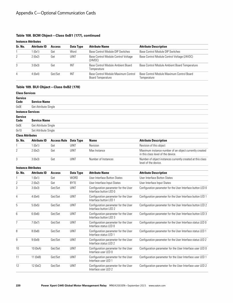
Appendix C—Optional Communication Cards
Instance Attributes
Sr. No. Attribute ID Access Data Type Attribute Name Attribute Description
1 1 (0x1) Get Word Base Control Module DIP Switches Base Control Module DIP Switches
2 2 (0x2) Get UINT Base Control Module Control Voltage (24VDC)
Base Control Module Control Voltage (24VDC)
3 3 (0x3) Get INT Base Control Module Ambient Board Temperature
Base Control Module Ambient Board Temperature
4 4 (0x4) Get/Set INT Base Control Module Maximum Control Board Temperature
Base Control Module Maximum Control Board Temperature
Table 109. BUI Object—Class 0xB2 (178)
Class Services
Service Code Service Name
0x0E Get Attribute Single
Instance Services
Service Code Service Name
0x0E Get Attribute Single
0x10 Set Attribute Single
Class Attributes
Sr. No. Attribute ID Access Rule Data Type Name Attribute Description
1 1 (0x1) Get UINT Revision Revision of this object
2 2 (0x2) Get UINT Max Instance Maximum instance number of an object currently created in this class level of the device.
3 3 (0x3) Get UINT Number of Instances Number of object instances currently created at this class level of the device.
Instance Attributes
Sr. No. Attribute ID Access Data Type Attribute Name Attribute Description
1 1 (0x1) Get WORD User Interface Button States User Interface Button States
2 2 (0x2) Get BYTE User Interface Input States User Interface Input States
3 3 (0x3) Get/Set UINT Configuration parameter for the User Interface button LED 0
Configuration parameter for the User Interface button LED 0
4 4 (0x4) Get/Set UINT Configuration parameter for the User Interface button LED 1
Configuration parameter for the User Interface button LED 1
5 5 (0x5) Get/Set UINT Configuration parameter for the User Interface button LED 2
Configuration parameter for the User Interface button LED 2
6 6 (0x6) Get/Set UINT Configuration parameter for the User Interface button LED 3
Configuration parameter for the User Interface button LED 3
7 7 (0x7) Get/Set UINT Configuration parameter for the User Interface status LED 0
Configuration parameter for the User Interface status LED 0
8 8 (0x8) Get/Set UINT Configuration parameter for the User Interface status LED 1
Configuration parameter for the User Interface status LED 1
9 9 (0x9) Get/Set UINT Configuration parameter for the User Interface status LED 2
Configuration parameter for the User Interface status LED 2
10 10 (0xA) Get/Set UINT Configuration parameter for the User Interface user LED 0
Configuration parameter for the User Interface user LED 0
11 11 (0xB) Get/Set UINT Configuration parameter for the User Interface user LED 1
Configuration parameter for the User Interface user LED 1
12 12 (0xC) Get/Set UINT Configuration parameter for the User Interface user LED 2
Configuration parameter for the User Interface user LED 2
Table 108. BCM Object—Class 0xB1 (177), continued
220 Power Xpert C445 Global Motor Management Relay MN042003EN—September 2015 www.eaton.com

Appendix C—Optional Communication Cards
Instance Attributes
Sr. No. Attribute ID Access Data Type Attribute Name Attribute Description
13 13 (0xD) Get/Set UINT CFG parameter for the User Interface button 0 function
CFG parameter for the User Interface button 0 function
14 14 (0xE) Get/Set UINT CFG parameter for the User Interface button 1 function
CFG parameter for the User Interface button 1 function
15 15 (0xF) Get/Set UINT CFG parameter for the User Interface button 2 function
CFG parameter for the User Interface button 2 function
16 16 (0x10) Get/Set UINT CFG parameter for the User Interface button 3 function
CFG parameter for the User Interface button 3 function
17 17 (0x11) Get/Set UINT CFG parameter for the User Interface button 4 function
CFG parameter for the User Interface button 4 function
18 18 (0x12) Get/Set UINT User Interface LED 0 Color cfg parameter User Interface LED 0 Color cfg parameter
19 19 (0x13) Get/Set UINT User Interface LED 1 Color cfg parameter User Interface LED 1 Color cfg parameter
20 20 (0x14) Get/Set UINT User Interface LED 2 Color cfg parameter User Interface LED 2 Color cfg parameter
21 21 (0x15) Get/Set UINT User Interface LED 3 Color cfg parameter User Interface LED 3 Color cfg parameter
22 22 (0x16) Get/Set UINT User Interface LED 4 Color cfg parameter User Interface LED 4 Color cfg parameter
23 23 (0x17) Get/Set UINT User Interface LED 5 Color cfg parameter User Interface LED 5 Color cfg parameter
24 24 (0x18) Get/Set UINT User Interface LED 6 Color cfg parameter User Interface LED 6 Color cfg parameter
25 25 (0x19) Get/Set UINT User Interface LED 7 Color cfg parameter User Interface LED 7 Color cfg parameter
26 26 (0x20) Get/Set UINT User Interface LED 8 Color cfg parameter User Interface LED 8 Color cfg parameter
Table 110. Option Card Object—Class 0xB3 (179)
Class Services
Service Code Service Name
0x0E Get Attribute Single
Instance Services
Service Code Service Name
0x0E Get Attribute Single
0x10 Set Attribute Single
Class Attributes
Sr. No. Attribute ID Access Rule Data Type Name Attribute Description
1 1 (0x1) Get UINT Revision Revision of this object
2 2 (0x2) Get UINT Max Instance Maximum instance number of an object currently created in this class level of the device.
3 3 (0x3) Get UINT Number of Instances Number of object instances currently created at this class level of the device.
Instance Attributes
Sr. No. Attribute ID Access Data Type Attribute Name Attribute Description
1 1 (0x1) Get/Set UINT Modbus Comm Loss Timeout Value (ms) Modbus Comm Loss Timeout Value (ms)
2 2 (0x2) Get/Set UINT Web services Comm Loss Timeout Value (ms)
Web services Comm Loss Timeout Value (ms)
3 3 (0x3) Get/Set BOOL Master Key for Hardcoded IP Address Selection
Master Key for Hardcoded IP Address Selection
4 4 (0x4) Get Array of 4 USINT
Active IP Address Active IP Address
Table 109. BUI Object—Class 0xB2 (178), continued
Power Xpert C445 Global Motor Management Relay MN042003EN—September 2015 www.eaton.com 221

Appendix C—Optional Communication Cards
Instance Attributes
Sr. No. Attribute ID Access Data Type Attribute Name Attribute Description
5 5 (0x5) Get Array of 4 USINT
Active Subnet Mask Active Subnet Mask
6 6 (0x6) Get Array of 4 USINT
Active Default Gateway Active Default Gateway
7 7 (0x7) Get/Set Array of 4 USINT
Static IP Address Static IP Address
8 8 (0x8) Get/Set Array of 4 USINT
Static Subnet Mask Static Subnet Mask
9 9 (0x9) Get/Set Array of 4 USINT
Static Default Gateway Static Default Gateway
10 10 (0xA) Get/Set UINT Ethernet PHY 1 - Link Speed Select Ethernet PHY 1 - Link Speed Select
11 11 (0xB) Get UINT Ethernet PHY 1 - Link Speed Actual Ethernet PHY 1 - Link Speed Actual
12 12 (0xC) Get/Set BOOL Ethernet PHY 1 - Duplex Select Ethernet PHY 1 - Duplex Select
13 13 (0xD) Get BOOL Ethernet PHY 1 - Duplex Actual Ethernet PHY 1 - Duplex Actual
14 14 (0xE) Get/Set BOOL Ethernet PHY 1 - Link Auto-Negotiate Enable
Ethernet PHY 1 - Link Auto-Negotiate Enable
15 15 (0xF) Get USINT Ethernet PHY 1 - Link Auto-Negotiate State
Ethernet PHY 1 - Link Auto-Negotiate State
16 16 (0x10) Get/Set BOOL Ethernet PHY 1 - Port Enable Ethernet PHY 1 - Port Enable
17 17 (0x11) Get/Set UINT Ethernet PHY 2 - Link Speed Select Ethernet PHY 2 - Link Speed Select
18 18 (0x12) Get UINT Ethernet PHY 2 - Link Speed Actual Ethernet PHY 2 - Link Speed Actual
19 19 (0x13) Get/Set BOOL Ethernet PHY 2 - Duplex Select Ethernet PHY 2 - Duplex Select
20 20 (0x14) Get BOOL Ethernet PHY 2 - Duplex Actual Ethernet PHY 2 - Duplex Actual
21 21 (0x15) Get/Set BOOL Ethernet PHY 2 - Link Auto-Negotiate Enable
Ethernet PHY 2 - Link Auto-Negotiate Enable
22 22 (0x16) Get USINT Ethernet PHY 2 - Link Auto-Negotiate State
Ethernet PHY 2 - Link Auto-Negotiate State
23 23 (0x17) Get/Set BOOL Ethernet PHY 2 - Port Enable Ethernet PHY 2 - Port Enable
24 24 (0x18) Get/Set BOOL ACD Enable ACD Enable
25 25 (0x19) Ge USINT ACD Conflict State ACD Conflict State
26 26 (0x1A) Get/Set USINT ACD Conflicted State ACD Conflicted State
27 27 (0x1B) Get/Set USINT ACD Conflicted Device MAC ACD Conflicted Device MAC
28 28 (0x1C) Get Array of 6 USINT
Ethernet MAC Address Ethernet MAC Address
Table 111. Port Object—Class 0xF4 (244)
Class Services
Service Code Service Name
0x0E Get Attribute Single
0x01 Get Attributes All
Instance Services
Service Code Service Name
0x0E Get Attribute Single
0x01 Get Attributes All
Table 110. Option Card Object—Class 0xB3 (179), continued
222 Power Xpert C445 Global Motor Management Relay MN042003EN—September 2015 www.eaton.com
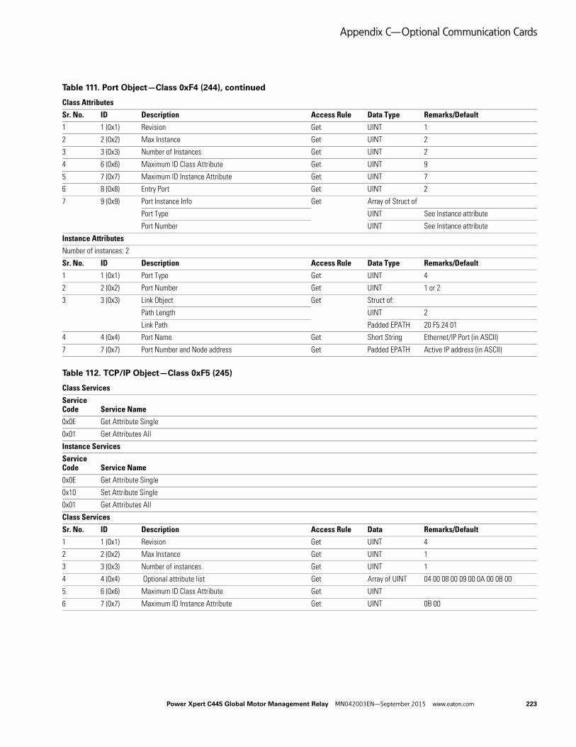
Appendix C—Optional Communication Cards
Class Attributes
Sr. No. ID Description Access Rule Data Type Remarks/Default
1 1 (0x1) Revision Get UINT 1
2 2 (0x2) Max Instance Get UINT 2
3 3 (0x3) Number of Instances Get UINT 2
4 6 (0x6) Maximum ID Class Attribute Get UINT 9
5 7 (0x7) Maximum ID Instance Attribute Get UINT 7
6 8 (0x8) Entry Port Get UINT 2
7 9 (0x9) Port Instance Info Get Array of Struct of
Port Type UINT See Instance attribute
Port Number UINT See Instance attribute
Instance Attributes
Number of instances: 2
Sr. No. ID Description Access Rule Data Type Remarks/Default
1 1 (0x1) Port Type Get UINT 4
2 2 (0x2) Port Number Get UINT 1 or 2
3 3 (0x3) Link Object Get Struct of:
Path Length UINT 2
Link Path Padded EPATH 20 F5 24 01
4 4 (0x4) Port Name Get Short String Ethernet/IP Port (in ASCII)
7 7 (0x7) Port Number and Node address Get Padded EPATH Active IP address (in ASCII)
Table 112. TCP/IP Object—Class 0xF5 (245)
Class Services
Service Code Service Name
0x0E Get Attribute Single
0x01 Get Attributes All
Instance Services
Service Code Service Name
0x0E Get Attribute Single
0x10 Set Attribute Single
0x01 Get Attributes All
Class Services
Sr. No. ID Description Access Rule Data Remarks/Default
1 1 (0x1) Revision Get UINT 4
2 2 (0x2) Max Instance Get UINT 1
3 3 (0x3) Number of instances Get UINT 1
4 4 (0x4) Optional attribute list Get Array of UINT 04 00 08 00 09 00 0A 00 0B 00
5 6 (0x6) Maximum ID Class Attribute Get UINT
6 7 (0x7) Maximum ID Instance Attribute Get UINT 0B 00
Table 111. Port Object—Class 0xF4 (244), continued
Power Xpert C445 Global Motor Management Relay MN042003EN—September 2015 www.eaton.com 223

Appendix C—Optional Communication Cards
Instance Attributes
Sr. No. ID Description Access Rule Data Type Remarks
1 1 (0x1) Status Get DWORD 01 00 00 00
2 2 (0x2) Configuration Capability Get DWORD F4 00 00 00
3 3 (0x3) Configuration Control Get / Set DWORD 02-dhcp, 0- static
4 4 (0x4) Physical Link Get STRUCT of
Path Size UINT 0
Path Padded EPATH 0
5 5 (0x5) Interface Configuration Get / Set Struct of:-NV
IP Address UDINT 192.168.1.254
Network Mask UDINT 255.255.255.0
Gateway Address UDINT 192.168.1.1
Name Server UDINT 0
Name Server 2 UDINT 0
Domain Name STRING 0
6 6 (0x6) Host Name Get / Set STRING 0
7 8 (0x8) TTL Value Get USINT 1
8 9 (0x9) Multicast Configuration Get Struct of:
Alloc Control USINT 0
Reserved USINT 0
Number of Mcast UINT 0x20
Starting Multicast Address DWORD 80 20 C0 EE
9 10 (0xA) SelectAcd Set / Get BOOL 1
10 11 (0xB) Last Conflict Detected Set / Get Struct of:
ACD activity USINT 0
Remote MAC Array of 6 USINT 0
ARP PDU Array of28 USINT 0
11 13 (0xD) Encapsulation Inactivity Timeout Set / Get UINT 0 = Disable1-3600 = timeout in secondsDefault = 120
Table 113. Ethernet Link Object—Class 0xF6 (246)
Class Services
Service Code Service Name
0x0E Get Attribute Single
0x01 Get Attributes All
Instance Services
Service Code Service Name
0x0E Get Attribute Single
0x10 Set Attribute Single
0x01 Get Attributes All
Table 112. TCP/IP Object—Class 0xF5 (245), continued
224 Power Xpert C445 Global Motor Management Relay MN042003EN—September 2015 www.eaton.com
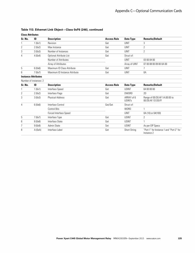
Appendix C—Optional Communication Cards
Class Attributes
Sr. No. ID Description Access Rule Data Type Remarks/Default
1 1 (0x1) Revision Get UINT 3
2 2 (0x2) Max Instance Get UINT 2
3 3 (0x3) Number of Instances Get UINT 2
4 4 (0x4) Optional Attribute List Get Struct of:
Number of Attributes UINT 03 00 04 00
Array of Attributes Array of UINT 07 00 08 00 09 00 0A 00
5 6 (0x6) Maximum ID Class Attribute Get UINT 7
6 7 (0x7) Maximum ID Instance Attribute Get UINT 0A
Instance Attributes
Number of instances: 2
Sr. No. ID Description Access Rule Data Type Remarks/Default
1 1 (0x1) Interface Speed Get UDINT 64 00 00 00
2 2 (0x2) Interface Flags Get DWORD 2D
3 3 (0x3) Physical Address Get ARRAY of 6 USINTs
Range of 00:D0:AF:1A:00:00 to 00:D0:AF:1D:D0:FF
4 6 (0x6) Interface Control Get/Set Struct of:
Control Bits WORD 1
Forced Interface Speed UINT 0A (10) or 64(100)
5 7 (0x7) Interface Type Get USINT 2
6 8 (0x8) Interface State Get USINT 1
7 9 (0x9) Admin State Set USINT As per EIP Specs
8 A (0xA) Interface Label Get Short String “Port 1” for Instance 1 and “Port 2” for Instance 2
Table 113. Ethernet Link Object—Class 0xF6 (246), continued
Power Xpert C445 Global Motor Management Relay MN042003EN—September 2015 www.eaton.com 225
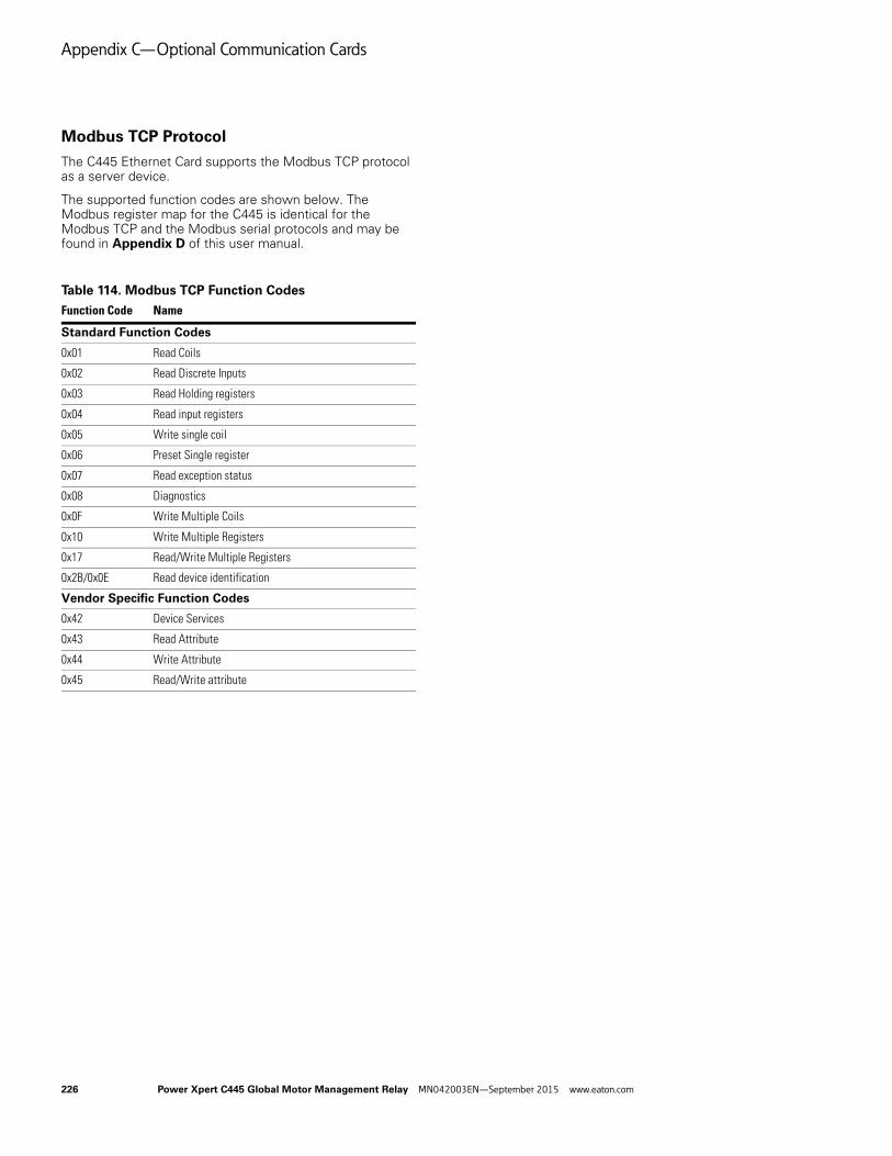
Appendix C—Optional Communication Cards
Modbus TCP Protocol
The C445 Ethernet Card supports the Modbus TCP protocol as a server device.
The supported function codes are shown below. The Modbus register map for the C445 is identical for the Modbus TCP and the Modbus serial protocols and may be found in Appendix D of this user manual.
Table 114. Modbus TCP Function Codes
Function Code Name
Standard Function Codes
0x01 Read Coils
0x02 Read Discrete Inputs
0x03 Read Holding registers
0x04 Read input registers
0x05 Write single coil
0x06 Preset Single register
0x07 Read exception status
0x08 Diagnostics
0x0F Write Multiple Coils
0x10 Write Multiple Registers
0x17 Read/Write Multiple Registers
0x2B/0x0E Read device identification
Vendor Specific Function Codes
0x42 Device Services
0x43 Read Attribute
0x44 Write Attribute
0x45 Read/Write attribute
226 Power Xpert C445 Global Motor Management Relay MN042003EN—September 2015 www.eaton.com
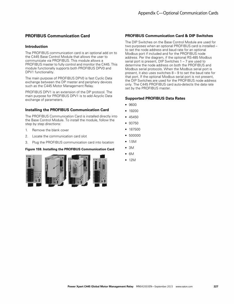
Appendix C—Optional Communication Cards
PROFIBUS Communication Card
Introduction
The PROFIBUS communication card is an optional add on to the C445 Base Control Module that allows the user to communicate via PROFIBUS. This module allows a PROFIBUS master to fully control and monitor the C445. This module functionally supports both PROFIBUS DPV0 and DPV1 functionality.
The main purpose of PROFIBUS DPV0 is fast Cyclic Data exchange between the DP master and periphery devices such as the C445 Motor Management Relay.
PROFIBUS DPV1 is an extension of the DP protocol. The main purpose for PROFIBUS DPV1 is to add Acyclic Data exchange of parameters.
Installing the PROFIBUS Communication Card
The PROFIBUS Communication Card is installed directly into the Base Control Module. To install the module, follow the step by step directions:
1. Remove the blank cover
2. Locate the communication card slot
3. Plug the PROFIBUS communication card into location
Figure 159. Installing the PROFIBUS Communication Card
PROFIBUS Communication Card & DIP Switches
The DIP Switches on the Base Control Module are used for two purposes when an optional PROFIBUS card is installed – to set the node address and baud rate for an optional Modbus port if included and for the PROFIBUS node address. Per the diagram, if the optional RS-485 Modbus serial port is present, DIP Switches 1 – 7 are used to determine the node address on both the PROFIBUS and Modbus serial protocols. When the Modbus serial port is present, it also uses switches 8 – 9 to set the baud rate for that port. If the optional Modbus serial port is not present, the DIP Switches are used for the PROFIBUS node address only. The C445 PROFIBUS card auto-detects the data rate set by the PROFIBUS master.
Supported PROFIBUS Data Rates
● 9600
● 19200
● 45450
● 93750
● 187500
● 500000
● 1.5M
● 3M
● 6M
● 12M
Power Xpert C445 Global Motor Management Relay MN042003EN—September 2015 www.eaton.com 227

Appendix C—Optional Communication Cards
Figure 160. Base Control Module DIP Switches with PROFIBUS Card
Table 115. Modbus Data Rate
PROFIBUS Cable Connection Options
The PROFIBUS card provides two options for PROFIBUS cable connections
1. PROFIBUS 9-pin D-SUB connector
2. 3-position screw connector with the following pin assignment:
● Pin 1 – RxD/TxD negative (green)
● Pin 2 – RxD/TxD positive (red)
● Pin 3 – Protective Earth
Note: The DIP Switches located beside the 3-position connector are only used when the 3-position connector is used for connecting the card to the PROFIBUS network. These switches must be turned Off if the D-shell connector is used to connect this card to PROFIBUS. These switches are used to turn network termination On/Off. If the 3-position connector is used to connect the C445 PROFIBUS card to the PROFIBUS network and if this card is an end device on the network, turn both switches On to enable termination. Otherwise, turn both switches Off to disable termination.
PROFIBUS D-shell connector information is shown below.
Table 116. PROFIBUS D-Shell Connector Specifications
Table 117. DB-9 Connector
Configuring using the inControl software tool
There is a Modbus serial DTM/Driver for the inControl software tool. This DTM is used to communicate from a computer running the inControl software tool using either a USB to micro USB cable or a USB to RS-485 serial cable. These interfaces may be used to connect to the C445 Motor Management Relay. Refer to the inControl software tool user manual for additional information (publication MN040013EN).
Configuring using The C445 PROFIBUS GSD file
The GSD file for the C445 Motor Management Relay may be found at the Eaton website:
http://www.eaton.com
This file is compatible with any PROFIBUS software used to configure a PROFIBUS network. It provides input/output information for cyclic polling, configuration file parameters and diagnostic data. It also contains parameter information that may be used for acyclic messaging.
B1 B0 Rate
0 0 Software Configurable
0 1 9600
1 0 115200
1 1 19200
Items Value
Terminal DB9 connector (Female) or5.00mm connector (male)
Data transfer method RS-485 half-duplex
Cable Twisted pair (1pair and shield)
Isolation 500 Vdc
Protocol PROFIBUS DP-V1
Baud rate 9.6K~12M
Addresses 3~125
Pin # Purpose
Housing Shield, Connected to PE
1 Not used (or Shield, shield or protect GND)
2 Not used (or M24, Minus 24V output Voltage)
3 RXD/TXD-P, Positive of Receive or Transmit signal
4 RTS, Request To Send
5 DGND, GND of signal (Isolated GND from RS-485 side)
6 VP, +5V, (Voltage- Plus, Isolated 5V from RS-485side)
7 Not used (or P24, Plus 24V Output Voltage)
8 RXD/TXD-N, Negative of Receive or Transmit signal
9 Not used (or CNTR_N, Control-N)
228 Power Xpert C445 Global Motor Management Relay MN042003EN—September 2015 www.eaton.com

Appendix C—Optional Communication Cards
PROFIBUS Card LED Definitions
Table 118. PROFIBUS Card LED Definitions
Note1 In the table above, while there are only two LEDs, the LED labeled BF acts as both the Active and BF LED.
C445 Cyclic (Polling)
The most common way of exchanging data with the C445 is via cyclic messages from a PROFIBUS master. The master sends control data to the C445 and reads monitoring data from the C445. Typically the control information involves a single or more bytes to instruct the C445 to run the motor or reset a fault. Data read from the C445 typically involves running status and fault state, along with motor parameters such as motor current, voltage, power and so on. The GSD file for the C445, available from the Eaton website defines the cyclic modules used to read and write to a C445 by the PROFIBUS master. The GSD file is installed into the PROFIBUS master’s programming software and used to configure the master for the data it will exchange with the C445.
The following are the various modules from the C445 GSD file:
Each module contains a different number of input and output bytes. There are 15 different Modules, where any 1 or 2 of these modules may be selected for each C445.
Module 1: Motor Management Profile as per IEC 61915-2, Command format 200 and Monitor Format 200
This profile is the only one that does not have selectable data. The I/O data is fixed. This profile includes the following:
Output data: The Motor Control Word (2 bytes).
Input data: The Motor Status word and Average Current Scaled (4 bytes total).
The Motor Control Word is defined as follows.
Bit 0: Run ReverseBit 1: ReservedBit 2: Run ForwardBit 3: ReservedBit 4: ReservedBit 5: ReservedBit 6: ResetBit 7: ReservedBits 8-15: Reserved
The Motor Status Word is defined as follows:
Bit 0: Running ReverseBit 1: ReservedBit 2: Running ForwardBit 3: Overload WarningBit 4: ReservedBit 5: ReservedBit 6: FaultBit 7: WarningBits 8-15: Reserved
State Wait_Param state Wait_CFG state Data exchange DP_Error state Fault State
PROFIBUS display state 1
No Communication, Master Offline
Communication No Data Ex
Everything OK CFG_Error, Parameterization Error,
H/W ID Fault, Board revision Fault, Incorrect Slave address, Fault on BCM
LED Profibus Active (Green)
ON ON ON ON NA
LED_SF(Red) OFF OFF OFF OFF ON
LED_BF(Red) ON Flashing(500 mSec) OFF Flashing(500 mSec) NA
Power Xpert C445 Global Motor Management Relay MN042003EN—September 2015 www.eaton.com 229

Appendix C—Optional Communication Cards
Module 2: Cyclic Module 2
This profile includes one input byte. Each bit is selectable via the C445 GSD file installed in the PROFIBUS master’s configuration software tool.
Module 3: Cyclic Module 3
This profile includes 2 input bytes. Each bit is selectable via the C445 GSD file installed in the PROFIBUS master’s configuration software tool.
Module 4: Cyclic Module 4
This profile includes 1 output byte. Each bit is selectable via the C445 GSD file installed in the PROFIBUS master’s configuration software tool, under the “Slave” module.
Module 5: Cyclic Module 5
This profile includes 2 output bytes. Each bit is selectable via the C445 GSD file installed in the PROFIBUS master’s configuration software tool, under the “Slave” module.
Module 6: Cyclic Module 6
This profile includes 2 input bytes and 2 output bytes. Each input bit is selectable via the C445 GSD file installed in the PROFIBUS master’s configuration software tool. Each output bit is selectable via the C445 GSD file installed in the PROFIBUS master’s configuration software tool, under the “Slave” module.
Module 7: Cyclic Module 7
This profile includes 8 input bytes and 4 output bytes. 4 word parameters may be selected for the input data and 2 word parameters for the output data. The input data is selectable under the module in the PROFIBUS master’s programming software and the output data under the “Slave” module.
Module 8: Cyclic Module 8
This profile includes total 6 output bytes and 10 input bytes. 16 output bits are selectable via the C445 GSD file installed in the PROFIBUS master’s configuration software tool, under the “Slave” module. 16 input bits are selectable via the C445 GSD file installed in the PROFIBUS master’s configuration software tool. 4 word parameters may be selected for the input data and 2 word parameters for the output data.
Module 9: Cyclic Module 9
This profile includes 2 input bytes. 1 word parameter may be selected for the input data. The input data is selectable under the module in the PROFIBUS master’s programming software.
Module 10: Cyclic Module 10
This profile includes 4 input bytes. 2 word parameters may be selected for the input data. The input data is selectable under the module in the PROFIBUS master’s programming software.
Module 11: Cyclic Module 11
This profile includes 8 input bytes. 4 word parameters may be selected for the input data. The input data is selectable under the module in the PROFIBUS master’s programming software.
Module 12: Cyclic Module 12
This profile includes 16 input bytes. 8 word parameters may be selected for the input data. The input data is selectable under the module in the PROFIBUS master’s programming software.
Module 13: Cyclic Module 13
This profile includes 32 input bytes and 4 output bytes. 16 word parameters may be selected for the input data and 2 word parameters for the output data. The input data is selectable under the module in the PROFIBUS master’s programming software and the output data under the “Slave” module.
Module 14: Cyclic Module 14
This profile includes 2 output bytes. 1 word parameter may be selected. This output data is selectable under the “Slave module in the PROFIBUS master’s programming software.
Module 15: Cyclic Module 15
This profile includes 4 output bytes. 2 word parameters may be selected. This output data is selectable under the “Slave module in the PROFIBUS master’s programming software.
230 Power Xpert C445 Global Motor Management Relay MN042003EN—September 2015 www.eaton.com
Appendix C—Optional Communication Cards
Acyclic PROFIBUS Messages
The C445 supports the acyclic messages added with the DPV1 version of PROFIBUS. All parameters in the C445 are mapped using Modbus Register addresses. This register map can be found in Appendix D. Modbus commands and registers are used to read and write parameters for the C445 via acyclic PROFIBUS messages.
Reading Data from a C445 via Acyclic Messages
1. An acyclic write message must be sent by the master containing a Modbus read command.
2. An acyclic read message must be sent by the master to obtain the data.
Reading data:
1. Send an acyclic write message per the following:
Slot number (always 0 for the C445)Index: 45Data length including the Modbus command in bytes
Data Field:
a. 03 Modbus Read command (1 byte)
b. Two bytes representing the Modbus register address in hexadecimal or decimal depending on what the master requires. (2 bytes)
c. Length of data to be read. This is the number of 16-bit registers being requested.
2. Send acyclic read message to obtain the requested data per the following:
Slot number (always 0 for the C445)Index: 45Data Length in bytes (example, if 1 register is being read, this length would be 2)
Writing data:
Only one step is needed to write data as follows:
Slot number (always 0 for the C445)Index 45Length in bytes, including the Modbus command in bytes
Data Field:
a. 06 Modbus single register write command (1 byte)
b. Two bytes representing the Modbus register address in hexadecimal or decimal depending on what the master requires. (2 bytes)
c. The two bytes (1 word) of data
Acyclic Message Examples
Example #1: Read the Active Fault Code from the C445.
The Active Fault Code is Modbus register 312 (address = 311) from Appendix D. This register address is converted to two hexadecimal bytes and two decimal bytes below:
01 37 hexadecimal01 55 decimal
Note: The byte format depends on the PROFIBUS master.
The following two acyclic messages must be sent by the PROFIBUS master to the C445 to read the Active Fault Code:
1. Acyclic write message:
Slot 0Index 45Length 4 bytes03 Modbus read command01 37 hex or 01 55 decimal01 length (1 register to read)
2. Acyclic read message:
Slot 0Index 45Length 2 bytes
Example #2: Write to the Base Control Module Field Output Control word.
The Modbus register address for this parameter from Appendix D is 601 (address = 600). This register is converted to two hexadecimal bytes or two decimal bytes below:
02 58 hexadecimal02 88 decimal
Note: The byte format depends on the PROFIBUS master.
The following acyclic message must be sent to write a value of 128 to the System Services register to issue a Soft Reset (bit 6 = 1, so the value is 64 decimal).
1. Acyclic write message:
Slot 0Index 45Length 5 bytes
Data Field:
06 Command02 58 hexadecimal or 02 88 decimalData: 00 40 hexadecimal or 00 64 decimal
Power Xpert C445 Global Motor Management Relay MN042003EN—September 2015 www.eaton.com 231

Appendix C—Optional Communication Cards
PROFIBUS Diagnostics
The C445 PROFIBUS communication card uses extended diagnostics to provide the status information along with fault and warning data relevant to the operation of the system.
Any time a fault condition is present in the system, the “ext.diag.” bit (bit3 in first diagnostic data byte) will be set high, indicating to the Master, a high level diagnostic message and fault is present. The C445 PROFIBUS communication card will also set the appropriate word/bit/bits in diagnostic data bytes 11 and 16 to indicate to the user the reason for the fault/warning condition.
When the fault condition is cleared, the “ext. diag.” bit (bit3 in first diagnostic data byte) will also clear, indicating to the Master that the C445 system is healthy and ready for operation.
Table 119. C445 Diagnostic Telegram Details
Below picture shows how diagnostics message is sent to Master.
Byte No. Description
1 to 6 PROFIBUS DP standard diagnostics
7 to 10 Extended diagnostics header
11 to 12 Active Fault Code (Modbus Register No.312)
13 to 16 Warning Status Bits (Modbus Register No.318)
232 Power Xpert C445 Global Motor Management Relay MN042003EN—September 2015 www.eaton.com

Appendix C—Optional Communication Cards
Extended diagnostics frame has 10 bytes where first 4 bytes are header followed by 6 bytes fault and warning data. For example in above picture 0A 81 01 00 bytes are header information. 1A 00 00 00 00 00 are diagnostics information where 1A 00 forms a fault code word 0x001A, which means Communication lost with MM. 00 00 00 00 are the warning bits per Modbus register 318. When there is no fault or warning in the system, all 6 bytes of diagnostics data will be 0.
Optional Features
Freeze Mode
Freeze Mode is supported in the C445 PROFIBUS communication card.
Sync Mode
Sync Mode is supported in the C445 PROFIBUS communication card.
Fail Safe Mode
Fail Safe Mode is supported in the C445 PROFIBUS communication card. On the reception of a Clear Data frame from the Master, the C445 PROFIBUS communication module outputs will go to fail safe mode–outputs disabled.
Power Xpert C445 Global Motor Management Relay MN042003EN—September 2015 www.eaton.com 233
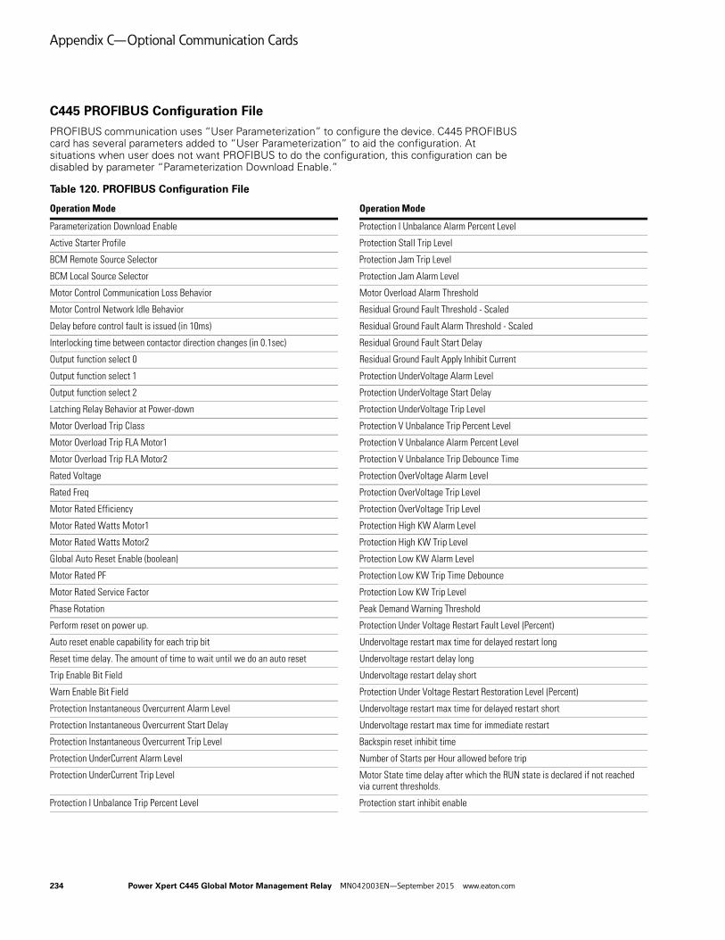
Appendix C—Optional Communication Cards
C445 PROFIBUS Configuration File
PROFIBUS communication uses “User Parameterization” to configure the device. C445 PROFIBUS card has several parameters added to “User Parameterization” to aid the configuration. At situations when user does not want PROFIBUS to do the configuration, this configuration can be disabled by parameter “Parameterization Download Enable.”
Table 120. PROFIBUS Configuration File
Operation Mode Operation Mode
Parameterization Download Enable Protection I Unbalance Alarm Percent Level
Active Starter Profile Protection Stall Trip Level
BCM Remote Source Selector Protection Jam Trip Level
BCM Local Source Selector Protection Jam Alarm Level
Motor Control Communication Loss Behavior Motor Overload Alarm Threshold
Motor Control Network Idle Behavior Residual Ground Fault Threshold - Scaled
Delay before control fault is issued (in 10ms) Residual Ground Fault Alarm Threshold - Scaled
Interlocking time between contactor direction changes (in 0.1sec) Residual Ground Fault Start Delay
Output function select 0 Residual Ground Fault Apply Inhibit Current
Output function select 1 Protection UnderVoltage Alarm Level
Output function select 2 Protection UnderVoltage Start Delay
Latching Relay Behavior at Power-down Protection UnderVoltage Trip Level
Motor Overload Trip Class Protection V Unbalance Trip Percent Level
Motor Overload Trip FLA Motor1 Protection V Unbalance Alarm Percent Level
Motor Overload Trip FLA Motor2 Protection V Unbalance Trip Debounce Time
Rated Voltage Protection OverVoltage Alarm Level
Rated Freq Protection OverVoltage Trip Level
Motor Rated Efficiency Protection OverVoltage Trip Level
Motor Rated Watts Motor1 Protection High KW Alarm Level
Motor Rated Watts Motor2 Protection High KW Trip Level
Global Auto Reset Enable (boolean) Protection Low KW Alarm Level
Motor Rated PF Protection Low KW Trip Time Debounce
Motor Rated Service Factor Protection Low KW Trip Level
Phase Rotation Peak Demand Warning Threshold
Perform reset on power up. Protection Under Voltage Restart Fault Level (Percent)
Auto reset enable capability for each trip bit Undervoltage restart max time for delayed restart long
Reset time delay. The amount of time to wait until we do an auto reset Undervoltage restart delay long
Trip Enable Bit Field Undervoltage restart delay short
Warn Enable Bit Field Protection Under Voltage Restart Restoration Level (Percent)
Protection Instantaneous Overcurrent Alarm Level Undervoltage restart max time for delayed restart short
Protection Instantaneous Overcurrent Start Delay Undervoltage restart max time for immediate restart
Protection Instantaneous Overcurrent Trip Level Backspin reset inhibit time
Protection UnderCurrent Alarm Level Number of Starts per Hour allowed before trip
Protection UnderCurrent Trip Level Motor State time delay after which the RUN state is declared if not reached via current thresholds.
Protection I Unbalance Trip Percent Level Protection start inhibit enable
234 Power Xpert C445 Global Motor Management Relay MN042003EN—September 2015 www.eaton.com

Appendix C—Optional Communication Cards
C445 PROFIBUS Bit Mapping Parameters
C445 has option of mapping individual bits in input/output modules. Below are the bits available for bit mapping.
C445 PROFIBUS Cyclic/Acyclic Writable Parameters
Table 121. Bit Mapping Parameters for Cyclic/Acyclic Writeable Parameters
Note: For more information about any of the parameters listed above, refer to System Configuration and
Commissioning on Page 47 or Appendix E.
Table 122. Fieldbus Motor Control Bits
C445 PROFIBUS Cyclic/Acyclic Readable Parameters
Table 123. Bit Mapping Parameters for Cyclic/Acyclic Readable Parameters
System Services is one of the selections for an output data word. The following are decimal values that when sent to the C445 with the System Services word cause the C445 to perform the designated function:
0: No Active Service1: Clear Fault Queue2: Clear Trip Snapshot3: Test Trip4: Re-pair external modules5: Factory Reset6: Soft Reset7: Reset Fault8: Proof Test
BCM Field Output Control Word is one of the selections for an output data word. The following are the bits that control the 3 outputs on the Base Control Module:
Bit 0: Output 1Bit 1: Output 2Bit 2: Output 3 (if a Base Control Module with the
latching relay option is being used, this bit is used to Set this output)
Bit 3: This bit is only used when a BCM with the latching relay option is used. This bit resets the latching relay output.
Bit Description Parameter Description
Run 1 Fieldbus Motor Control
Run 2 Fieldbus Motor Control
Reserved Fieldbus Motor Control
Fault Reset Fieldbus Motor Control
Reserved Fieldbus Motor Control
Test Trip Fieldbus Motor Control
Reserved Fieldbus Motor Control
Reserved Fieldbus Motor Control
BCM Field Output control0 BCM Field Output control
BCM Field Output control1 BCM Field Output control
BCM Field Output control2 BCM Field Output control
BCM Field Output control3 BCM Field Output control
Bit Position Bit Description
Bit 0 Run 1
Bit 1 Run 2
Bit 2 Reserved
Bit 3 Fault Reset
Bit 4 Reserved
Bit 5 Test Trip
Bit 6 Reserved
Bit 7 Reserved
Bit Description Parameter Description
Running 1 BCM Status Word
Running 2 BCM Status Word
Remote Enabled BCM Status Word
Faulted BCM Status Word
Warning BCM Status Word
Inhibited BCM Status Word
Ready BCM Status Word
Up to Speed BCM Status Word
FIELD INPUT 1 Digital Input Status of BUI
FIELD INPUT 2 Digital Input Status of BUI
FIELD INPUT 3 Digital Input Status of BUI
FIELD INPUT 4 Digital Input Status of BUI
Power Xpert C445 Global Motor Management Relay MN042003EN—September 2015 www.eaton.com 235
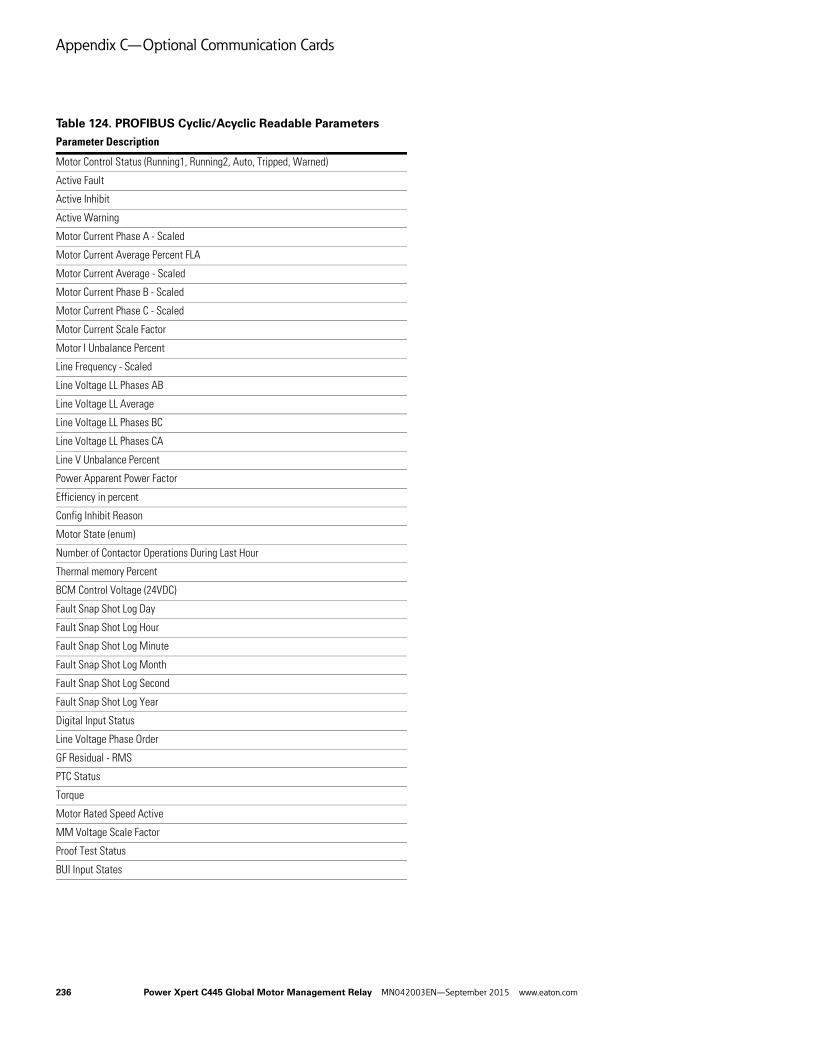
Appendix C—Optional Communication Cards
Table 124. PROFIBUS Cyclic/Acyclic Readable Parameters
Parameter Description
Motor Control Status (Running1, Running2, Auto, Tripped, Warned)
Active Fault
Active Inhibit
Active Warning
Motor Current Phase A - Scaled
Motor Current Average Percent FLA
Motor Current Average - Scaled
Motor Current Phase B - Scaled
Motor Current Phase C - Scaled
Motor Current Scale Factor
Motor I Unbalance Percent
Line Frequency - Scaled
Line Voltage LL Phases AB
Line Voltage LL Average
Line Voltage LL Phases BC
Line Voltage LL Phases CA
Line V Unbalance Percent
Power Apparent Power Factor
Efficiency in percent
Config Inhibit Reason
Motor State (enum)
Number of Contactor Operations During Last Hour
Thermal memory Percent
BCM Control Voltage (24VDC)
Fault Snap Shot Log Day
Fault Snap Shot Log Hour
Fault Snap Shot Log Minute
Fault Snap Shot Log Month
Fault Snap Shot Log Second
Fault Snap Shot Log Year
Digital Input Status
Line Voltage Phase Order
GF Residual - RMS
PTC Status
Torque
Motor Rated Speed Active
MM Voltage Scale Factor
Proof Test Status
BUI Input States
236 Power Xpert C445 Global Motor Management Relay MN042003EN—September 2015 www.eaton.com
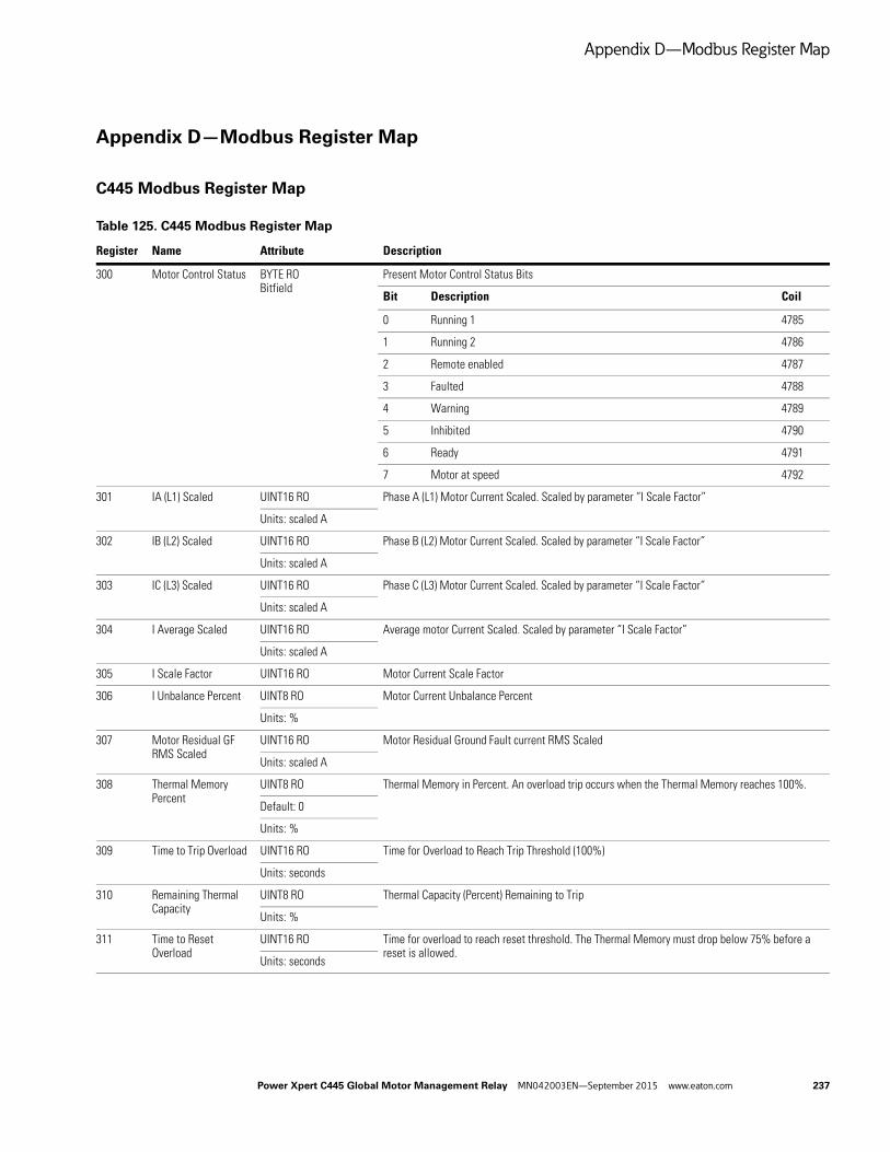
Appendix D—Modbus Register Map
Appendix D—Modbus Register Map
C445 Modbus Register Map
Table 125. C445 Modbus Register Map
Register Name Attribute Description
300 Motor Control Status BYTE ROBitfield
Present Motor Control Status Bits
Bit Description Coil
0 Running 1 4785
1 Running 2 4786
2 Remote enabled 4787
3 Faulted 4788
4 Warning 4789
5 Inhibited 4790
6 Ready 4791
7 Motor at speed 4792
301 IA (L1) Scaled UINT16 RO Phase A (L1) Motor Current Scaled. Scaled by parameter “I Scale Factor”
Units: scaled A
302 IB (L2) Scaled UINT16 RO Phase B (L2) Motor Current Scaled. Scaled by parameter “I Scale Factor”
Units: scaled A
303 IC (L3) Scaled UINT16 RO Phase C (L3) Motor Current Scaled. Scaled by parameter “I Scale Factor”
Units: scaled A
304 I Average Scaled UINT16 RO Average motor Current Scaled. Scaled by parameter “I Scale Factor”
Units: scaled A
305 I Scale Factor UINT16 RO Motor Current Scale Factor
306 I Unbalance Percent UINT8 RO Motor Current Unbalance Percent
Units: %
307 Motor Residual GF RMS Scaled
UINT16 RO Motor Residual Ground Fault current RMS Scaled
Units: scaled A
308 Thermal Memory Percent
UINT8 RO Thermal Memory in Percent. An overload trip occurs when the Thermal Memory reaches 100%.
Default: 0
Units: %
309 Time to Trip Overload UINT16 RO Time for Overload to Reach Trip Threshold (100%)
Units: seconds
310 Remaining Thermal Capacity
UINT8 RO Thermal Capacity (Percent) Remaining to Trip
Units: %
311 Time to Reset Overload
UINT16 RO Time for overload to reach reset threshold. The Thermal Memory must drop below 75% before a reset is allowed.
Units: seconds
Power Xpert C445 Global Motor Management Relay MN042003EN—September 2015 www.eaton.com 237

Appendix D—Modbus Register Map
312 Active Fault UINT16 RODefault: 0Enum
Active Fault
Value Description
0 No Faults
1 Under voltage
2 Over voltage
3 External GF
4 Residual GF
5 Current phase loss
6 Current unbalance
7 Instantaneous over current
8 Jam
9 PF Deviation
10 Voltage phase loss
11 Voltage unbalance
12 Frequency deviation fast
13 Frequency deviation slow
14 Under current
15 High power
16 Low power
17 Contactor failure
18 Starts limit exceeded
19 Overload
20 Stall
21 Phase rotation mismatch
22 PTC—See PTC State for details
23 Under voltage restart
24 Measurement Module fault
25 Communication loss on active fieldbus
26 Measurement Module not available or communication loss with the module
27 User Interface not available or communication loss with the module
28 Test trip was triggered
29 Option Card not available or communication loss with the module
30 RTC / Backup Memory Option Board NV memory fail
31 Currently connected User Interface does not match with what was connected before
32 Currently connected Measurement Module does not match with what was connected before
33 Currently connected Option Card does not match with what was connected before
34 Measurement Module firmware is incompatible
35 User Interface firmware is incompatible
Table 125. C445 Modbus Register Map, continued
Register Name Attribute Description
238 Power Xpert C445 Global Motor Management Relay MN042003EN—September 2015 www.eaton.com
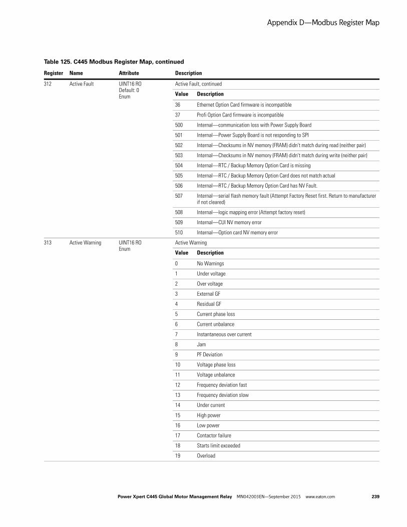
Appendix D—Modbus Register Map
312 Active Fault UINT16 RODefault: 0Enum
Active Fault, continued
Value Description
36 Ethernet Option Card firmware is incompatible
37 Profi Option Card firmware is incompatible
500 Internal—communication loss with Power Supply Board
501 Internal—Power Supply Board is not responding to SPI
502 Internal—Checksums in NV memory (FRAM) didn't match during read (neither pair)
503 Internal—Checksums in NV memory (FRAM) didn't match during write (neither pair)
504 Internal—RTC / Backup Memory Option Card is missing
505 Internal—RTC / Backup Memory Option Card does not match actual
506 Internal—RTC / Backup Memory Option Card has NV Fault.
507 Internal—serial flash memory fault (Attempt Factory Reset first. Return to manufacturer if not cleared)
508 Internal—logic mapping error (Attempt factory reset)
509 Internal—CUI NV memory error
510 Internal—Option card NV memory error
313 Active Warning UINT16 ROEnum
Active Warning
Value Description
0 No Warnings
1 Under voltage
2 Over voltage
3 External GF
4 Residual GF
5 Current phase loss
6 Current unbalance
7 Instantaneous over current
8 Jam
9 PF Deviation
10 Voltage phase loss
11 Voltage unbalance
12 Frequency deviation fast
13 Frequency deviation slow
14 Under current
15 High power
16 Low power
17 Contactor failure
18 Starts limit exceeded
19 Overload
Table 125. C445 Modbus Register Map, continued
Register Name Attribute Description
Power Xpert C445 Global Motor Management Relay MN042003EN—September 2015 www.eaton.com 239
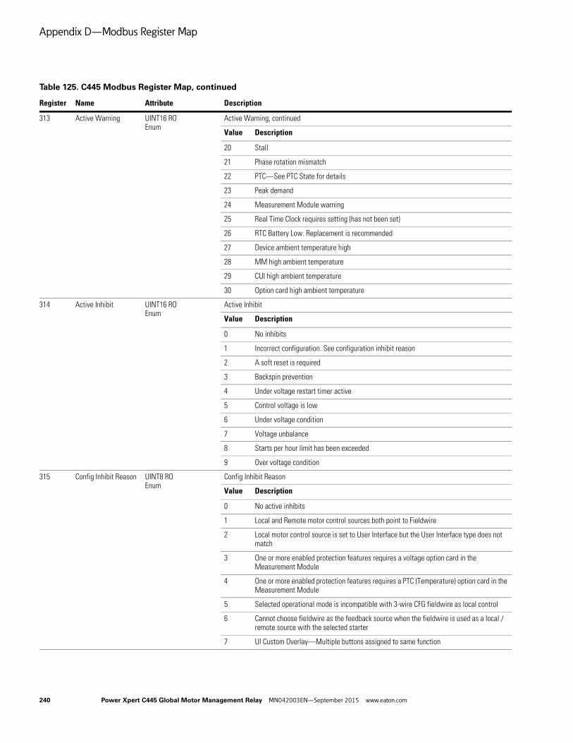
Appendix D—Modbus Register Map
313 Active Warning UINT16 ROEnum
Active Warning, continued
Value Description
20 Stall
21 Phase rotation mismatch
22 PTC—See PTC State for details
23 Peak demand
24 Measurement Module warning
25 Real Time Clock requires setting (has not been set)
26 RTC Battery Low. Replacement is recommended
27 Device ambient temperature high
28 MM high ambient temperature
29 CUI high ambient temperature
30 Option card high ambient temperature
314 Active Inhibit UINT16 ROEnum
Active Inhibit
Value Description
0 No inhibits
1 Incorrect configuration. See configuration inhibit reason
2 A soft reset is required
3 Backspin prevention
4 Under voltage restart timer active
5 Control voltage is low
6 Under voltage condition
7 Voltage unbalance
8 Starts per hour limit has been exceeded
9 Over voltage condition
315 Config Inhibit Reason UINT8 ROEnum
Config Inhibit Reason
Value Description
0 No active inhibits
1 Local and Remote motor control sources both point to Fieldwire
2 Local motor control source is set to User Interface but the User Interface type does not match
3 One or more enabled protection features requires a voltage option card in the Measurement Module
4 One or more enabled protection features requires a PTC (Temperature) option card in the Measurement Module
5 Selected operational mode is incompatible with 3-wire CFG fieldwire as local control
6 Cannot choose fieldwire as the feedback source when the fieldwire is used as a local / remote source with the selected starter
7 UI Custom Overlay—Multiple buttons assigned to same function
Table 125. C445 Modbus Register Map, continued
Register Name Attribute Description
240 Power Xpert C445 Global Motor Management Relay MN042003EN—September 2015 www.eaton.com

Appendix D—Modbus Register Map
315 Config Inhibit Reason UINT8 ROEnum
Config Inhibit Reason, continued
Value Description
8 UI Custom Overlay—Multiple button LEDs assigned to the same function
9 UI Custom Overlay—Multiple status LEDs assigned to the same function
10 Selected operational mode is incompatible with the connected UI
11 The General Purpose I/O operational mode does not use fieldwire as a control source
316 Tripped Status Bits BYTE ROArray size: 4Bitfield
Trip Status Bits Indicate the Trip Reason
Bit Description Coil
0 Under voltage 5041
1 Over voltage 5042
2 External ground fault 5043
3 Residual ground fault 5044
4 Current phase loss 5045
5 Current unbalance 5046
6 Instantaneous over current 5047
7 Jam 5048
8 Power factor deviation 5049
9 Voltage phase loss 5050
10 Voltage unbalance 5051
11 Frequency deviation fast 5052
12 Frequency deviation slow 5053
13 Under current 5054
14 High power 5055
15 Low power 5056
16 Reserved 5057
17 Starts limit exceeded 5058
18 Overload 5059
19 Stall 5060
20 Phase rotation mismatch 5061
21 PTC 5062
22 Under voltage restart 5063
23 Peak demand 5064
Table 125. C445 Modbus Register Map, continued
Register Name Attribute Description
Power Xpert C445 Global Motor Management Relay MN042003EN—September 2015 www.eaton.com 241

Appendix D—Modbus Register Map
318 Warning Status Bits BYTE ROArray size: 4Bitfield
Warning Status Bits Indicate the Reason for a Warning
Bit Description Coil
0 Under voltage 5073
1 Over voltage 5074
2 External ground fault 5075
3 Residual ground fault 5076
4 Current phase loss 5077
5 Current unbalance 5078
6 Instantaneous over current 5079
7 Jam 5080
8 Power factor deviation 5081
9 Voltage phase loss 5082
10 Voltage unbalance 5083
11 Frequency deviation fast 5084
12 Frequency deviation slow 5085
13 Under current 5086
14 High power 5087
15 Low power 5088
16 Reserved 5089
17 Starts limit exceeded 5090
18 Overload 5091
19 Stall 5092
20 Phase rotation mismatch 5093
21 PTC 5094
22 Under voltage restart 5095
23 Peak demand 5096
320 Base Control Module Control Voltage
UINT16 RO Base Control Module Control voltage measured
Units: mV
321 Voltage AB (L1-L2) UINT16 RO Supply Line-to-Line Voltage AB (L1-L2)
Units: V
322 Voltage BC (L2-L3) UINT16 RO Supply Line-to-Line Voltage BC (L2-L3)
Units: V
323 Voltage CA (L3-L1) UINT16 RO Supply Line-to-Line Voltage CA (L3-L1)
Units: V
324 Average Line-to-Line Voltage
UINT16 RO Supply Line-to-Line Voltage Average
Units: V
325 Voltage Unbalance Percent
UINT8 RO Supply Voltage Unbalance Percentage
Units: %
Table 125. C445 Modbus Register Map, continued
Register Name Attribute Description
242 Power Xpert C445 Global Motor Management Relay MN042003EN—September 2015 www.eaton.com

Appendix D—Modbus Register Map
326 Voltage Phase Order UINT8 ROEnum
Supply Phase Order. 0: unknown; 1: ABC (L1-L2-L3); 2: ACB (L1-L3-L2)
Value Description
0 Unknown
1 ABC (L1-L2-L3)
2 ACB (L1-L3-L2)
3 Voltage(L1-L2-L3) Current(L1-L3-L2)
4 Voltage(L1-L3-L2) Current(L1-L2-L3)
327 Total Watts SINT32 RO Total Real Power
Units: W
329 Total VA SINT32 RO Total Apparent Power
Units: VA
331 Total VARS SINT32 RO Total Reactive Power
Units: VAR
333 Power Factor Scaled SINT16 RO Apparent Power Factor in Percent (Scaled). A parameter value of 8512 is equal to 85.12% or 8512.
Units: 0.01%
334 Real Energy Scaled SINT32 RO Real Energy Scaled
Default: 0
Units: 0.1 kWh
Backup Mem
336 Reactive Energy Scaled
SINT32 RO Reactive Energy Scaled
Default: 0
Units: 0.1kVARh
Backup Mem
338 Apparent Energy Scaled
SINT32 RO Apparent Energy Scaled
Default: 0
Units: 0.1kVAh
Backup Mem
340 Real Energy (Resettable) Scaled
SINT32 RW NV Real Energy, User Resettable Scaled
Default: 0
Units: 0.1 kWh
Admin Lock
USB Lock
Backup Mem
342 Reactive Energy (Resettable) Scaled
SINT32 RW NV Reactive Energy, User Resettable Scaled
Default: 0
Units: 0.1kVARh
Admin Lock
USB Lock
Backup Mem
Table 125. C445 Modbus Register Map, continued
Register Name Attribute Description
Power Xpert C445 Global Motor Management Relay MN042003EN—September 2015 www.eaton.com 243
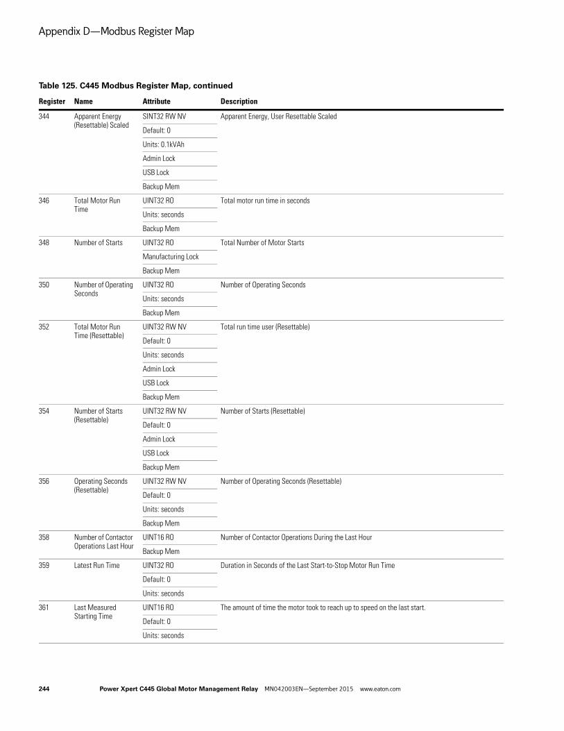
Appendix D—Modbus Register Map
344 Apparent Energy (Resettable) Scaled
SINT32 RW NV Apparent Energy, User Resettable Scaled
Default: 0
Units: 0.1kVAh
Admin Lock
USB Lock
Backup Mem
346 Total Motor Run Time
UINT32 RO Total motor run time in seconds
Units: seconds
Backup Mem
348 Number of Starts UINT32 RO Total Number of Motor Starts
Manufacturing Lock
Backup Mem
350 Number of Operating Seconds
UINT32 RO Number of Operating Seconds
Units: seconds
Backup Mem
352 Total Motor Run Time (Resettable)
UINT32 RW NV Total run time user (Resettable)
Default: 0
Units: seconds
Admin Lock
USB Lock
Backup Mem
354 Number of Starts (Resettable)
UINT32 RW NV Number of Starts (Resettable)
Default: 0
Admin Lock
USB Lock
Backup Mem
356 Operating Seconds (Resettable)
UINT32 RW NV Number of Operating Seconds (Resettable)
Default: 0
Units: seconds
Backup Mem
358 Number of Contactor Operations Last Hour
UINT16 RO Number of Contactor Operations During the Last Hour
Backup Mem
359 Latest Run Time UINT32 RO Duration in Seconds of the Last Start-to-Stop Motor Run Time
Default: 0
Units: seconds
361 Last Measured Starting Time
UINT16 RO The amount of time the motor took to reach up to speed on the last start.
Default: 0
Units: seconds
Table 125. C445 Modbus Register Map, continued
Register Name Attribute Description
244 Power Xpert C445 Global Motor Management Relay MN042003EN—September 2015 www.eaton.com

Appendix D—Modbus Register Map
362 I Average % of FLA (Nominal Current)
UINT16 RO Average Motor Current as Percentage of FLA (Nominal Current)
Units: %
363 Current Demand Value
UINT32 RO Latest estimate of the Demand
Units: W
365 Demand (Resettable) UINT32 RW NV Peak Demand, User Resettable
Default: 0
Range: 0 to 0
Units: W
Admin Lock
USB Lock
Backup Mem
367 Peak Demand Time Stamp
UINT32 RO Peak Demand Time Stamp (in Unix time)
Default: 0
Units: seconds
Admin Lock
USB Lock
Backup Mem
369 Maximum Start Current Floating Point
FLOAT RW NV Maximum Motor Starting Current Floating Point Format. This value can be set (typically to 0).
Default: 0
Units: A
Admin Lock
USB Lock
371 Maximum Start Current Scaled
UINT16 RW NV Max Motor Starting Current Scaled. Scaled by parameter “I Scale Factor.” This value can be set (typically to 0).
Default: 0
Units: scaled A
Admin Lock
USB Lock
372 Motor State (Current Based)
UINT8 ROEnum
Current based motor state. The motor state is determined by using the current presently measured. This state indication runs independent of the actual command being provided.
Value Description
0 Motor current indicates a stop
1 Motor current indicates motor is accelerating
2 Motor current indicates a running or at speed condition
373 Motor Speed RPM UINT16 RO Motor Speed in RPM
Units: 0.1 RPM
374 Motor Torque SINT16 RO Motor torque
Units: 0.01 Nm
375 Motor Efficiency Percent Scaled
UINT16 RO Motor Efficiency in Percentage scaled by 0.01%
Units: 0.01%
Table 125. C445 Modbus Register Map, continued
Register Name Attribute Description
Power Xpert C445 Global Motor Management Relay MN042003EN—September 2015 www.eaton.com 245
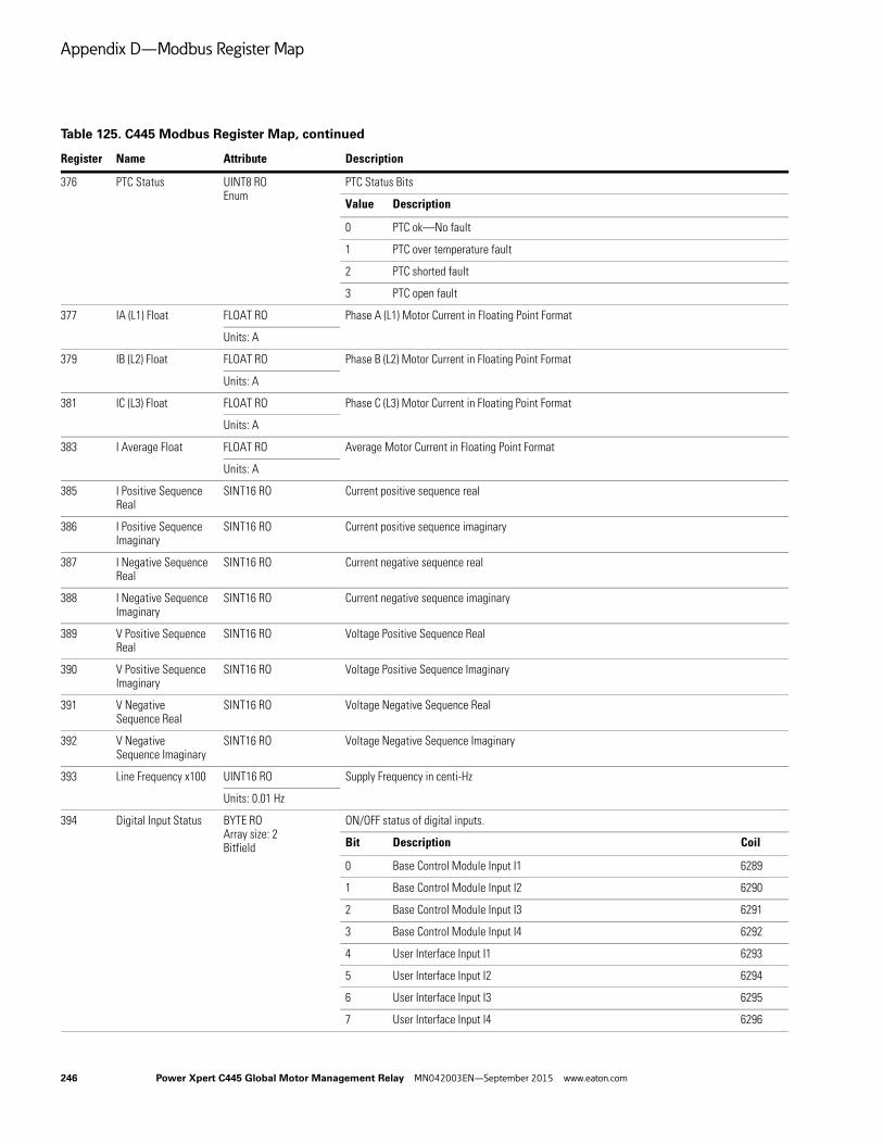
Appendix D—Modbus Register Map
376 PTC Status UINT8 ROEnum
PTC Status Bits
Value Description
0 PTC ok—No fault
1 PTC over temperature fault
2 PTC shorted fault
3 PTC open fault
377 IA (L1) Float FLOAT RO Phase A (L1) Motor Current in Floating Point Format
Units: A
379 IB (L2) Float FLOAT RO Phase B (L2) Motor Current in Floating Point Format
Units: A
381 IC (L3) Float FLOAT RO Phase C (L3) Motor Current in Floating Point Format
Units: A
383 I Average Float FLOAT RO Average Motor Current in Floating Point Format
Units: A
385 I Positive Sequence Real
SINT16 RO Current positive sequence real
386 I Positive Sequence Imaginary
SINT16 RO Current positive sequence imaginary
387 I Negative Sequence Real
SINT16 RO Current negative sequence real
388 I Negative Sequence Imaginary
SINT16 RO Current negative sequence imaginary
389 V Positive Sequence Real
SINT16 RO Voltage Positive Sequence Real
390 V Positive Sequence Imaginary
SINT16 RO Voltage Positive Sequence Imaginary
391 V Negative Sequence Real
SINT16 RO Voltage Negative Sequence Real
392 V Negative Sequence Imaginary
SINT16 RO Voltage Negative Sequence Imaginary
393 Line Frequency x100 UINT16 RO Supply Frequency in centi-Hz
Units: 0.01 Hz
394 Digital Input Status BYTE ROArray size: 2Bitfield
ON/OFF status of digital inputs.
Bit Description Coil
0 Base Control Module Input I1 6289
1 Base Control Module Input I2 6290
2 Base Control Module Input I3 6291
3 Base Control Module Input I4 6292
4 User Interface Input I1 6293
5 User Interface Input I2 6294
6 User Interface Input I3 6295
7 User Interface Input I4 6296
Table 125. C445 Modbus Register Map, continued
Register Name Attribute Description
246 Power Xpert C445 Global Motor Management Relay MN042003EN—September 2015 www.eaton.com

Appendix D—Modbus Register Map
395 Base Control Module Relay Status
BYTE RODefault: 0Bitfield
Base Control Module Relay Status
Bit Description Coil
0 Q1 state: (0) Open not energized / (1) Closed energized 6305
1 Q2 state: (0) Open not energized / (1) Closed energized 6306
2 Q3 State: (0) Open (latching: relay reset) / (1) Closed (latching: relay set) 6307
396 Base Control Module Dip Switches
WORD ROBitfield
Base Control Module Dip Switch Settings
Bit Description Coil
0 Switch 1 (close to connector) 6321
1 Switch 2 6322
2 Switch 3 6323
3 Switch 4 6324
4 Switch 5 6325
5 Switch 6 6326
6 Switch 7 6327
7 Switch 8 6328
8 Switch 9 6329
9 Switch 10 (USB—close to top) 6330
397 Base Control Module Control Bd Amb Temp
SINT16 RO Base Control Module Option board—ambient temperature measured on the PCB.
Units: ∫C
398 Base Control Module Max Bd Amb Temp
SINT16 RW NV Base Control Module Maximum ambient temperature measured on the PCB. This value can be set (typically to –40).
Default: –40
Units: ∫C
400 Proof Test Status UINT8 RODefault: 0Enum
Proof Test Status
Value Description
0 Proof test is idle (not triggered)
1 Proof test is running
2 Proof test passed
3 Proof test failed
500 Active Overload Trip FLA (Nominal Current) Scaled
UINT16 RO Active Overload Trip FLA (Nominal Current) Scaled is a read only parameter indicating the active FLA. If the application has two windings (and two FLA settings), this parameter will indicate the currently active motor winding setting, Scaled by parameter “I Scale Factor.”Default: 101 (RW)
Range: 1 to 65535 (RW)
Units: scaled A
501 Motor Rated Speed RPM active
UINT16 RO RPM nameplate rating of the active motor winding.
Default: 1750
Range: 300 to 3600
Units: RPM
502 Motor Rated HP Active Scaled
UINT32 RO hp nameplate rating of the active motor winding. This value is scaled by 0.01. For example if the motor is rated at 123.25 hp then this parameter should contain 12325.
Units: HPx100
Table 125. C445 Modbus Register Map, continued
Register Name Attribute Description
Power Xpert C445 Global Motor Management Relay MN042003EN—September 2015 www.eaton.com 247

Appendix D—Modbus Register Map
504 Motor Rated Watts Active
UINT32 RO Watts nameplate rating of the active motor winding.
Default: 14914
Range: 10 to 3728500
Units: W
506 Active Control Source
UINT8 ROEnum
Active Control Source
Value Description
0 No active control source
1 User Interface is the active control source
2 FieldBus is the active control source
3 FieldWire is the active control source
600 Fieldbus Motor Control
BYTE RWBitfieldUSB Lock
Fieldbus Motor ControlRun 1 Command Bit: This bit is Profile dependant. For example, this is the Run bit for a FVNR motor application or the Run FWD bit for a FVR applications.Run 2 Command Bit: This bit is Profile dependant. For example, this is not used for a FVNR motor application or is the Run REV Run for a FVR applications.Fault Reset: This resets an active fault if the fault condition is no longer present.Test Trip: This allows the user to trip the unit for test purposes. Use Fault Reset to reset the test trip condition.
Bit Description Coil
0 Run1 command bit 9585
1 Run2 command bit 9586
2 Reserved bit 9587
3 Reset fault bit 9588
4 Reserved bit 9589
5 Test trip the device bit 9590
601 Base Control Module Field Output control word
BYTE RWBitfield
ON / OFF Control for Available Base Control Module Field Outputs. The Profile type dictates which of these outputs are available as general purpose outputs. For example, Outputs 2 and 3 are available when the Direct profile is selected, while only Output 3 is available when the Reverser Profile is selected.
Bit Description Coil
0 Bit 0 9601
1 Bit 1 9602
2 Bit 2 9603
3 Bit 3 9604
Table 125. C445 Modbus Register Map, continued
Register Name Attribute Description
248 Power Xpert C445 Global Motor Management Relay MN042003EN—September 2015 www.eaton.com

Appendix D—Modbus Register Map
602 Remote Feedback Signal Parameter
BYTE RWBitfield
Parameter to write status of Controller input feedback.
Bit Description Coil
0 Network feedback input I1 9617
1 Network feedback input I2 9618
2 Network feedback input I3 9619
3 Network feedback input I4 9620
4 Network feedback input I5 9621
5 Network feedback input I6 9622
6 Network feedback input I7 9623
7 Network feedback input I8 9624
603 System Services UINT8 RWEnum
System services are used to execute device level commands. The command is automatically cleared after being processed.
Value Description
0 No Active Service
1 Clear fault queue
2 Clear trip snapshot
3 Test trip
4 Re-pair external modules
5 Factory reset
6 Soft reset
7 Reset Fault
8 Proof Test
Table 125. C445 Modbus Register Map, continued
Register Name Attribute Description
Power Xpert C445 Global Motor Management Relay MN042003EN—September 2015 www.eaton.com 249
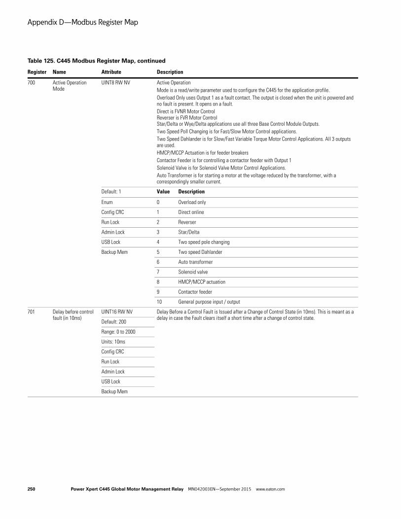
Appendix D—Modbus Register Map
700 Active Operation Mode
UINT8 RW NV Active Operation Mode is a read/write parameter used to configure the C445 for the application profile.Overload Only uses Output 1 as a fault contact. The output is closed when the unit is powered and no fault is present. It opens on a fault.Direct is FVNR Motor ControlReverser is FVR Motor ControlStar/Delta or Wye/Delta applications use all three Base Control Module Outputs.Two Speed Poll Changing is for Fast/Slow Motor Control applications.Two Speed Dahlander is for Slow/Fast Variable Torque Motor Control Applications. All 3 outputs are used.HMCP/MCCP Actuation is for feeder breakersContactor Feeder is for controlling a contactor feeder with Output 1Solenoid Valve is for Solenoid Valve Motor Control Applications.Auto Transformer is for starting a motor at the voltage reduced by the transformer, with a correspondingly smaller current.
Default: 1 Value Description
Enum 0 Overload only
Config CRC 1 Direct online
Run Lock 2 Reverser
Admin Lock 3 Star/Delta
USB Lock 4 Two speed pole changing
Backup Mem 5 Two speed Dahlander
6 Auto transformer
7 Solenoid valve
8 HMCP/MCCP actuation
9 Contactor feeder
10 General purpose input / output
701 Delay before control fault (in 10ms)
UINT16 RW NV Delay Before a Control Fault is Issued after a Change of Control State (in 10ms). This is meant as a delay in case the Fault clears itself a short time after a change of control state.
Default: 200
Range: 0 to 2000
Units: 10ms
Config CRC
Run Lock
Admin Lock
USB Lock
Backup Mem
Table 125. C445 Modbus Register Map, continued
Register Name Attribute Description
250 Power Xpert C445 Global Motor Management Relay MN042003EN—September 2015 www.eaton.com

Appendix D—Modbus Register Map
702 Control Interlocking Time
UINT16 RW NV Time delay between “forward to reverse” or “reverse to forward” direction change (in 0.1sec)
Default: 10
Range: 0 to 60000
Units: 10ms
Config CRC
Run Lock
Admin Lock
USB Lock
Backup Mem
703 Control Switching Time
UINT16 RW NV Time delay between switching from fast to slow which allows the motor time to slow down. (in 0.1 sec)
Default: 10
Range: 0 to 60000
Units: 10ms
Config CRC
Run Lock
Admin Lock
USB Lock
Backup Mem
704 Network contactor delay
UINT16 RW NV Settling time for network contactor before RUN contactor engages (in 10 ms)
Default: 5
Range: 0 to 2000
Units: 10ms
705 Max Star Winding Time
UINT16 RW NV The time after which the controller will transition to delta wiring when “up to speed” is NOT detected in the star winding
Default: 100
Range: 1 to 6000
Units: 100ms
Config CRC
Run Lock
Admin Lock
USB Lock
Backup Mem
706 Enable HMCP Actuation
BOOL RW NV Enable HMCP Actuation Control
Default: 0
Config CRC
Run Lock
Admin Lock
USB Lock
Backup Mem
Table 125. C445 Modbus Register Map, continued
Register Name Attribute Description
Power Xpert C445 Global Motor Management Relay MN042003EN—September 2015 www.eaton.com 251

Appendix D—Modbus Register Map
707 HMCP actuation pulse width
UINT16 RW NV HMCP actuation pulse width to trigger motor operator (in 1.0 ms)
Default: 500
Range: 100 to 60000
Units: ms
Config CRC
Run Lock
Admin Lock
USB Lock
Backup Mem
708 Solenoid open delay time
UINT16 RW NV Delay time for solenoid valve to open (in 10 ms)
Default: 0
Units: 10ms
Config CRC
Admin Lock
USB Lock
Backup Mem
709 Solenoid close delay time
UINT16 RW NV Delay time for solenoid valve to close (in 10 ms)
Default: 0
Units: 10ms
Config CRC
Admin Lock
USB Lock
Backup Mem
710 Non-energized state UINT8 RW NV Non energized state of solenoid valve
Default: 0 Value Description
Enum 0 Solenoid Valve normally closed—energize to open
Config CRC 1 Solenoid Valve normally open—energize to close
Admin Lock
USB Lock
Backup Mem
711 Local motor control source
UINT8 RW NV Selects local motor control source
Default: 0 Value Description
Enum 0 Auto detect User Interface
Config CRC 1 No local control
Run Lock 2 User Interface local control
Admin Lock 3 Fieldwire local control
USB Lock
Backup Mem
Table 125. C445 Modbus Register Map, continued
Register Name Attribute Description
252 Power Xpert C445 Global Motor Management Relay MN042003EN—September 2015 www.eaton.com
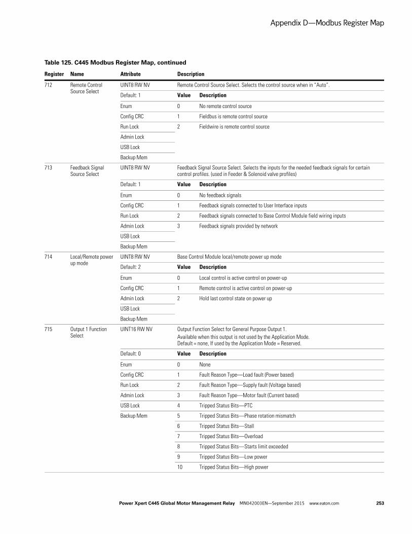
Appendix D—Modbus Register Map
712 Remote Control Source Select
UINT8 RW NV Remote Control Source Select. Selects the control source when in “Auto”.
Default: 1 Value Description
Enum 0 No remote control source
Config CRC 1 Fieldbus is remote control source
Run Lock 2 Fieldwire is remote control source
Admin Lock
USB Lock
Backup Mem
713 Feedback Signal Source Select
UINT8 RW NV Feedback Signal Source Select. Selects the inputs for the needed feedback signals for certain control profiles. (used in Feeder & Solenoid valve profiles)
Default: 1 Value Description
Enum 0 No feedback signals
Config CRC 1 Feedback signals connected to User Interface inputs
Run Lock 2 Feedback signals connected to Base Control Module field wiring inputs
Admin Lock 3 Feedback signals provided by network
USB Lock
Backup Mem
714 Local/Remote power up mode
UINT8 RW NV Base Control Module local/remote power up mode
Default: 2 Value Description
Enum 0 Local control is active control on power-up
Config CRC 1 Remote control is active control on power-up
Admin Lock 2 Hold last control state on power up
USB Lock
Backup Mem
715 Output 1 Function Select
UINT16 RW NV Output Function Select for General Purpose Output 1. Available when this output is not used by the Application Mode. Default = none, If used by the Application Mode = Reserved.
Default: 0 Value Description
Enum 0 None
Config CRC 1 Fault Reason Type—Load fault (Power based)
Run Lock 2 Fault Reason Type—Supply fault (Voltage based)
Admin Lock 3 Fault Reason Type—Motor fault (Current based)
USB Lock 4 Tripped Status Bits—PTC
Backup Mem 5 Tripped Status Bits—Phase rotation mismatch
6 Tripped Status Bits—Stall
7 Tripped Status Bits—Overload
8 Tripped Status Bits—Starts limit exceeded
9 Tripped Status Bits—Low power
10 Tripped Status Bits—High power
Table 125. C445 Modbus Register Map, continued
Register Name Attribute Description
Power Xpert C445 Global Motor Management Relay MN042003EN—September 2015 www.eaton.com 253

Appendix D—Modbus Register Map
715 Output 1 Function Select
UINT16 RW NV Output Function Select for General Purpose Output 1, continued
Value Description
11 Tripped Status Bits—Under current
12 Tripped Status Bits—Frequency deviation slow
13 Tripped Status Bits—Frequency deviation fast
14 Tripped Status Bits—Voltage unbalance
15 Tripped Status Bits—Voltage phase loss
16 Tripped Status Bits—Power factor deviation
17 Tripped Status Bits—Jam
18 Tripped Status Bits—Instantaneous over current
19 Tripped Status Bits—Current unbalance
20 Tripped Status Bits—Current phase loss
21 Tripped Status Bits—Residual ground fault
22 Motor Control Status—Motor at speed
23 Motor Control Status—Ready
24 Motor Control Status—Inhibited
25 Motor Control Status—Warning
26 Motor Control Status—Faulted
27 Motor Control Status—Remote enabled
28 Motor Control Status—Running 2
29 Motor Control Status—Running 1
30 Warning Status Bits—PTC
31 Warning Status Bits—Phase rotation mismatch
32 Warning Status Bits—Stall
33 Warning Status Bits—Overload
34 Warning Status Bits—Starts limit exceeded
35 Warning Status Bits—Low power
36 Warning Status Bits—High power
37 Warning Status Bits—Under current
38 Warning Status Bits—Frequency deviation slow
39 Warning Status Bits—Frequency deviation fast
40 Warning Status Bits—Voltage unbalance
41 Warning Status Bits—Voltage phase loss
42 Warning Status Bits—Power factor deviation
43 Warning Status Bits—Jam
44 Warning Status Bits—Instantaneous over current
45 Warning Status Bits—Current unbalance
46 Warning Status Bits—Current phase loss
Table 125. C445 Modbus Register Map, continued
Register Name Attribute Description
254 Power Xpert C445 Global Motor Management Relay MN042003EN—September 2015 www.eaton.com
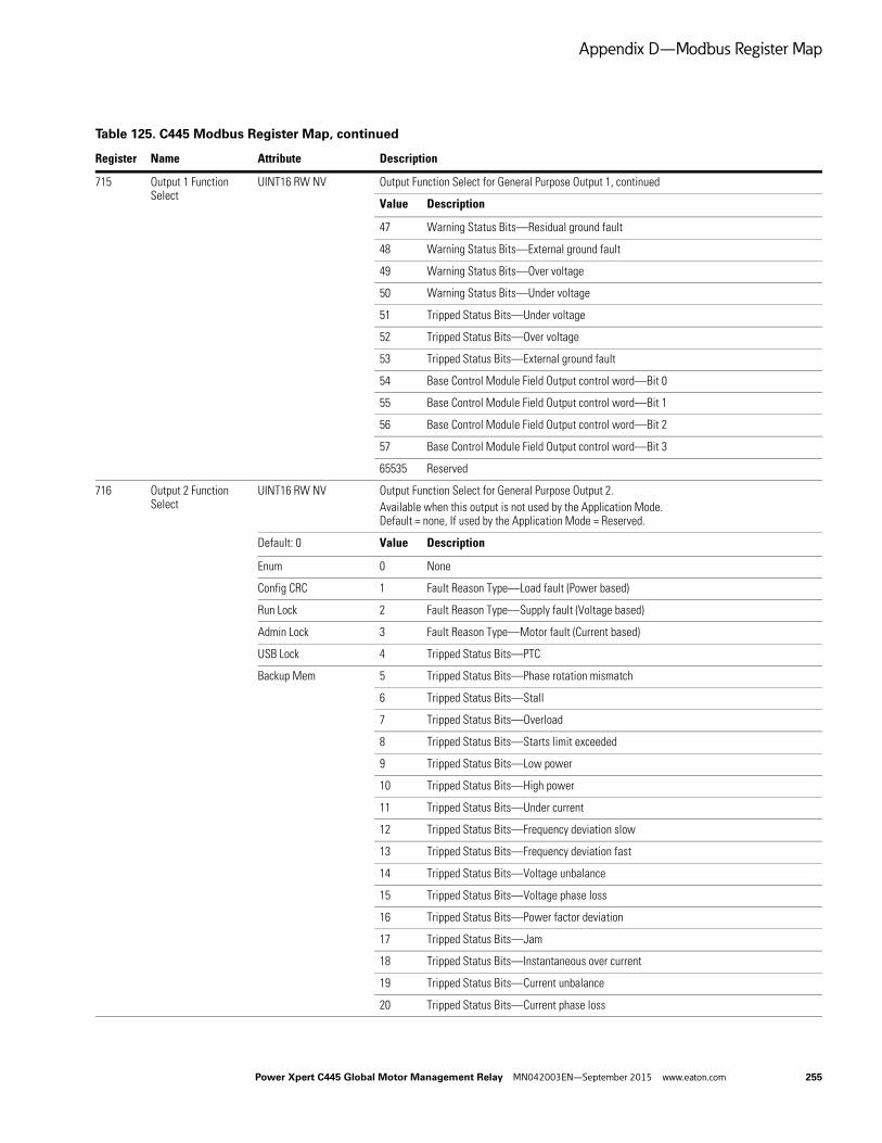
Appendix D—Modbus Register Map
715 Output 1 Function Select
UINT16 RW NV Output Function Select for General Purpose Output 1, continued
Value Description
47 Warning Status Bits—Residual ground fault
48 Warning Status Bits—External ground fault
49 Warning Status Bits—Over voltage
50 Warning Status Bits—Under voltage
51 Tripped Status Bits—Under voltage
52 Tripped Status Bits—Over voltage
53 Tripped Status Bits—External ground fault
54 Base Control Module Field Output control word—Bit 0
55 Base Control Module Field Output control word—Bit 1
56 Base Control Module Field Output control word—Bit 2
57 Base Control Module Field Output control word—Bit 3
65535 Reserved
716 Output 2 Function Select
UINT16 RW NV Output Function Select for General Purpose Output 2. Available when this output is not used by the Application Mode. Default = none, If used by the Application Mode = Reserved.
Default: 0 Value Description
Enum 0 None
Config CRC 1 Fault Reason Type—Load fault (Power based)
Run Lock 2 Fault Reason Type—Supply fault (Voltage based)
Admin Lock 3 Fault Reason Type—Motor fault (Current based)
USB Lock 4 Tripped Status Bits—PTC
Backup Mem 5 Tripped Status Bits—Phase rotation mismatch
6 Tripped Status Bits—Stall
7 Tripped Status Bits—Overload
8 Tripped Status Bits—Starts limit exceeded
9 Tripped Status Bits—Low power
10 Tripped Status Bits—High power
11 Tripped Status Bits—Under current
12 Tripped Status Bits—Frequency deviation slow
13 Tripped Status Bits—Frequency deviation fast
14 Tripped Status Bits—Voltage unbalance
15 Tripped Status Bits—Voltage phase loss
16 Tripped Status Bits—Power factor deviation
17 Tripped Status Bits—Jam
18 Tripped Status Bits—Instantaneous over current
19 Tripped Status Bits—Current unbalance
20 Tripped Status Bits—Current phase loss
Table 125. C445 Modbus Register Map, continued
Register Name Attribute Description
Power Xpert C445 Global Motor Management Relay MN042003EN—September 2015 www.eaton.com 255
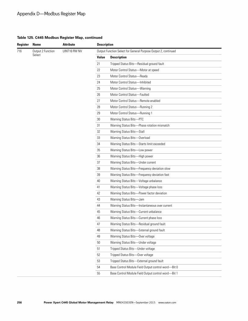
Appendix D—Modbus Register Map
716 Output 2 Function Select
UINT16 RW NV Output Function Select for General Purpose Output 2, continued
Value Description
21 Tripped Status Bits—Residual ground fault
22 Motor Control Status—Motor at speed
23 Motor Control Status—Ready
24 Motor Control Status—Inhibited
25 Motor Control Status—Warning
26 Motor Control Status—Faulted
27 Motor Control Status—Remote enabled
28 Motor Control Status—Running 2
29 Motor Control Status—Running 1
30 Warning Status Bits—PTC
31 Warning Status Bits—Phase rotation mismatch
32 Warning Status Bits—Stall
33 Warning Status Bits—Overload
34 Warning Status Bits—Starts limit exceeded
35 Warning Status Bits—Low power
36 Warning Status Bits—High power
37 Warning Status Bits—Under current
38 Warning Status Bits—Frequency deviation slow
39 Warning Status Bits—Frequency deviation fast
40 Warning Status Bits—Voltage unbalance
41 Warning Status Bits—Voltage phase loss
42 Warning Status Bits—Power factor deviation
43 Warning Status Bits—Jam
44 Warning Status Bits—Instantaneous over current
45 Warning Status Bits—Current unbalance
46 Warning Status Bits—Current phase loss
47 Warning Status Bits—Residual ground fault
48 Warning Status Bits—External ground fault
49 Warning Status Bits—Over voltage
50 Warning Status Bits—Under voltage
51 Tripped Status Bits—Under voltage
52 Tripped Status Bits—Over voltage
53 Tripped Status Bits—External ground fault
54 Base Control Module Field Output control word—Bit 0
55 Base Control Module Field Output control word—Bit 1
Table 125. C445 Modbus Register Map, continued
Register Name Attribute Description
256 Power Xpert C445 Global Motor Management Relay MN042003EN—September 2015 www.eaton.com
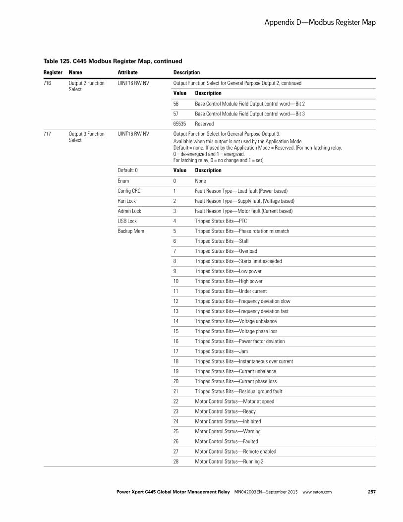
Appendix D—Modbus Register Map
716 Output 2 Function Select
UINT16 RW NV Output Function Select for General Purpose Output 2, continued
Value Description
56 Base Control Module Field Output control word—Bit 2
57 Base Control Module Field Output control word—Bit 3
65535 Reserved
717 Output 3 Function Select
UINT16 RW NV Output Function Select for General Purpose Output 3. Available when this output is not used by the Application Mode. Default = none, If used by the Application Mode = Reserved. (For non-latching relay, 0 = de-energized and 1 = energized. For latching relay, 0 = no change and 1 = set).
Default: 0 Value Description
Enum 0 None
Config CRC 1 Fault Reason Type—Load fault (Power based)
Run Lock 2 Fault Reason Type—Supply fault (Voltage based)
Admin Lock 3 Fault Reason Type—Motor fault (Current based)
USB Lock 4 Tripped Status Bits—PTC
Backup Mem 5 Tripped Status Bits—Phase rotation mismatch
6 Tripped Status Bits—Stall
7 Tripped Status Bits—Overload
8 Tripped Status Bits—Starts limit exceeded
9 Tripped Status Bits—Low power
10 Tripped Status Bits—High power
11 Tripped Status Bits—Under current
12 Tripped Status Bits—Frequency deviation slow
13 Tripped Status Bits—Frequency deviation fast
14 Tripped Status Bits—Voltage unbalance
15 Tripped Status Bits—Voltage phase loss
16 Tripped Status Bits—Power factor deviation
17 Tripped Status Bits—Jam
18 Tripped Status Bits—Instantaneous over current
19 Tripped Status Bits—Current unbalance
20 Tripped Status Bits—Current phase loss
21 Tripped Status Bits—Residual ground fault
22 Motor Control Status—Motor at speed
23 Motor Control Status—Ready
24 Motor Control Status—Inhibited
25 Motor Control Status—Warning
26 Motor Control Status—Faulted
27 Motor Control Status—Remote enabled
28 Motor Control Status—Running 2
Table 125. C445 Modbus Register Map, continued
Register Name Attribute Description
Power Xpert C445 Global Motor Management Relay MN042003EN—September 2015 www.eaton.com 257

Appendix D—Modbus Register Map
717 Output 3 Function Select
UINT16 RW NV Output Function Select for General Purpose Output 3, continued
Value Description
29 Motor Control Status—Running 1
30 Warning Status Bits—PTC
31 Warning Status Bits—Phase rotation mismatch
32 Warning Status Bits—Stall
33 Warning Status Bits—Overload
34 Warning Status Bits—Starts limit exceeded
35 Warning Status Bits—Low power
36 Warning Status Bits—High power
37 Warning Status Bits—Under current
38 Warning Status Bits—Frequency deviation slow
39 Warning Status Bits—Frequency deviation fast
40 Warning Status Bits—Voltage unbalance
41 Warning Status Bits—Voltage phase loss
42 Warning Status Bits—Power factor deviation
43 Warning Status Bits—Jam
44 Warning Status Bits—Instantaneous over current
45 Warning Status Bits—Current unbalance
46 Warning Status Bits—Current phase loss
47 Warning Status Bits—Residual ground fault
48 Warning Status Bits—External ground fault
49 Warning Status Bits—Over voltage
50 Warning Status Bits—Under voltage
51 Tripped Status Bits—Under voltage
52 Tripped Status Bits—Over voltage
53 Tripped Status Bits—External ground fault
54 Base Control Module Field Output control word—Bit 0
55 Base Control Module Field Output control word—Bit 1
56 Base Control Module Field Output control word—Bit 2
57 Base Control Module Field Output control word—Bit 3
65535 Reserved
Table 125. C445 Modbus Register Map, continued
Register Name Attribute Description
258 Power Xpert C445 Global Motor Management Relay MN042003EN—September 2015 www.eaton.com
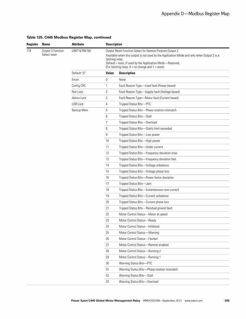
Appendix D—Modbus Register Map
718 Output 3 Function Select reset
UINT16 RW NV Output Reset Function Select for General Purpose Output 3. Available when this output is not used by the Application Mode and only when Output 3 is a latching relay. Default = none, If used by the Application Mode = Reserved. (For latching relay, 0 = no change and 1 = reset).
Default: 57 Value Description
Enum 0 None
Config CRC 1 Fault Reason Type—Load fault (Power based)
Run Lock 2 Fault Reason Type—Supply fault (Voltage based)
Admin Lock 3 Fault Reason Type—Motor fault (Current based)
USB Lock 4 Tripped Status Bits—PTC
Backup Mem 5 Tripped Status Bits—Phase rotation mismatch
6 Tripped Status Bits—Stall
7 Tripped Status Bits—Overload
8 Tripped Status Bits—Starts limit exceeded
9 Tripped Status Bits—Low power
10 Tripped Status Bits—High power
11 Tripped Status Bits—Under current
12 Tripped Status Bits—Frequency deviation slow
13 Tripped Status Bits—Frequency deviation fast
14 Tripped Status Bits—Voltage unbalance
15 Tripped Status Bits—Voltage phase loss
16 Tripped Status Bits—Power factor deviation
17 Tripped Status Bits—Jam
18 Tripped Status Bits—Instantaneous over current
19 Tripped Status Bits—Current unbalance
20 Tripped Status Bits—Current phase loss
21 Tripped Status Bits—Residual ground fault
22 Motor Control Status—Motor at speed
23 Motor Control Status—Ready
24 Motor Control Status—Inhibited
25 Motor Control Status—Warning
26 Motor Control Status—Faulted
27 Motor Control Status—Remote enabled
28 Motor Control Status—Running 2
29 Motor Control Status—Running 1
30 Warning Status Bits—PTC
31 Warning Status Bits—Phase rotation mismatch
32 Warning Status Bits—Stall
33 Warning Status Bits—Overload
Table 125. C445 Modbus Register Map, continued
Register Name Attribute Description
Power Xpert C445 Global Motor Management Relay MN042003EN—September 2015 www.eaton.com 259

Appendix D—Modbus Register Map
718 Output 3 Function Select reset
UINT16 RW NV Output Reset Function Select for General Purpose Output 3, continued
Value Description
38 Warning Status Bits—Frequency deviation slow
39 Warning Status Bits—Frequency deviation fast
40 Warning Status Bits—Voltage unbalance
41 Warning Status Bits—Voltage phase loss
42 Warning Status Bits—Power factor deviation
43 Warning Status Bits—Jam
44 Warning Status Bits—Instantaneous over current
45 Warning Status Bits—Current unbalance
46 Warning Status Bits—Current phase loss
47 Warning Status Bits—Residual ground fault
48 Warning Status Bits—External ground fault
49 Warning Status Bits—Over voltage
50 Warning Status Bits—Under voltage
51 Tripped Status Bits—Under voltage
52 Tripped Status Bits—Over voltage
53 Tripped Status Bits—External ground fault
54 Base Control Module Field Output control word—Bit 0
55 Base Control Module Field Output control word—Bit 1
56 Base Control Module Field Output control word—Bit 2
57 Base Control Module Field Output control word—Bit 3
65535 Reserved
719 Base Control Module Relay 3 Behavior
UINT8 RW NV Base Control Module Relay 3 Behavior
Default: 1 Value Description
Enum 0 Behave like a non-latching relay
Config CRC 1 Behave like a latching relay
Admin Lock
USB Lock
Backup Mem
720 Motor Control Communication Loss Behavior
UINT8 RW NV Defines the behavior of the motor control when communication times out.
Default: 0 Value Description
Enum 0 Stop (clear Run1/Run2) on communication loss event—no fault
Config CRC 1 Ignore communication loss and keep present state
Admin Lock 2 Set network motor control Run1 on comloss event
USB Lock 3 Set network motor control Run2 on comloss event
Backup Mem 4 Stop (clear Run1/Run2) on communication loss event and generate fault
Table 125. C445 Modbus Register Map, continued
Register Name Attribute Description
260 Power Xpert C445 Global Motor Management Relay MN042003EN—September 2015 www.eaton.com
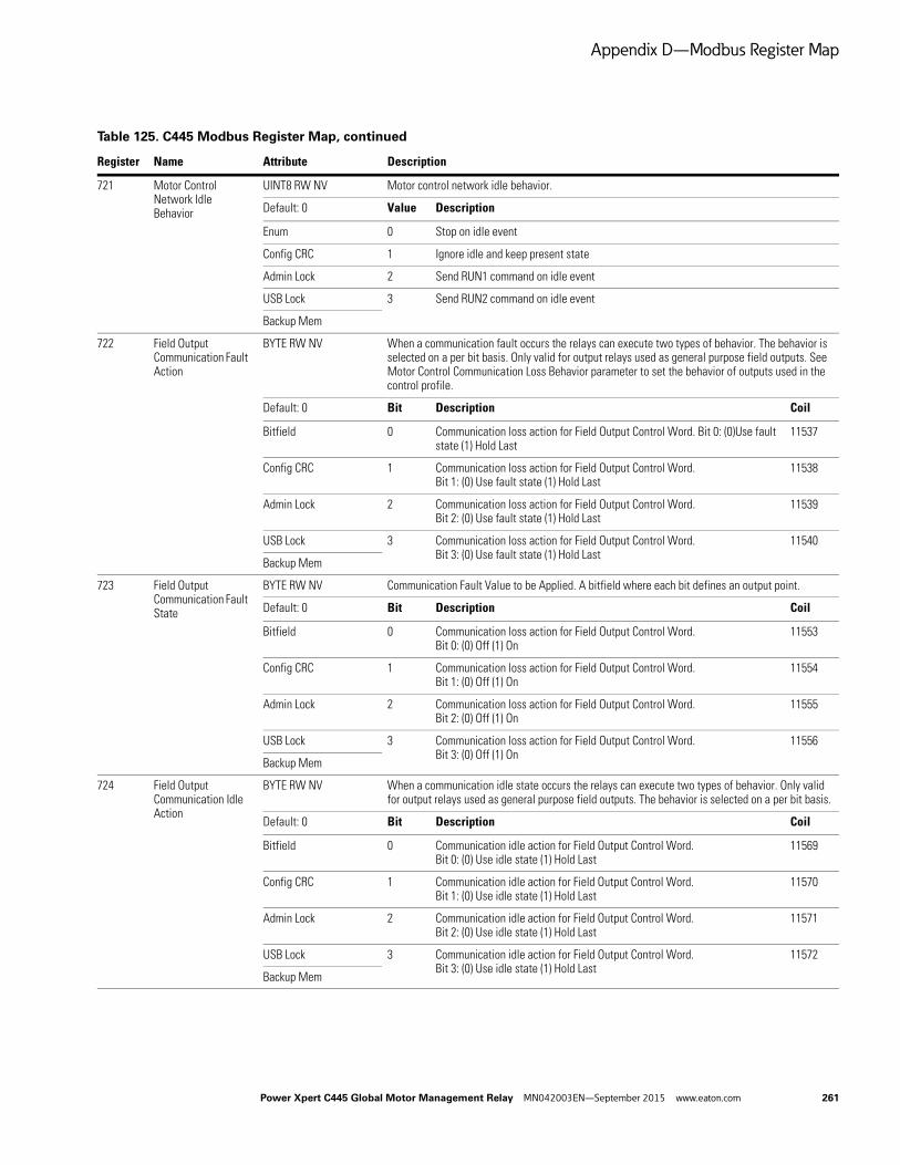
Appendix D—Modbus Register Map
721 Motor Control Network Idle Behavior
UINT8 RW NV Motor control network idle behavior.
Default: 0 Value Description
Enum 0 Stop on idle event
Config CRC 1 Ignore idle and keep present state
Admin Lock 2 Send RUN1 command on idle event
USB Lock 3 Send RUN2 command on idle event
Backup Mem
722 Field Output Communication Fault Action
BYTE RW NV When a communication fault occurs the relays can execute two types of behavior. The behavior is selected on a per bit basis. Only valid for output relays used as general purpose field outputs. See Motor Control Communication Loss Behavior parameter to set the behavior of outputs used in the control profile.
Default: 0 Bit Description Coil
Bitfield 0 Communication loss action for Field Output Control Word. Bit 0: (0)Use fault state (1) Hold Last
11537
Config CRC 1 Communication loss action for Field Output Control Word. Bit 1: (0) Use fault state (1) Hold Last
11538
Admin Lock 2 Communication loss action for Field Output Control Word. Bit 2: (0) Use fault state (1) Hold Last
11539
USB Lock 3 Communication loss action for Field Output Control Word. Bit 3: (0) Use fault state (1) Hold Last
11540
Backup Mem
723 Field Output Communication Fault State
BYTE RW NV Communication Fault Value to be Applied. A bitfield where each bit defines an output point.
Default: 0 Bit Description Coil
Bitfield 0 Communication loss action for Field Output Control Word. Bit 0: (0) Off (1) On
11553
Config CRC 1 Communication loss action for Field Output Control Word. Bit 1: (0) Off (1) On
11554
Admin Lock 2 Communication loss action for Field Output Control Word. Bit 2: (0) Off (1) On
11555
USB Lock 3 Communication loss action for Field Output Control Word. Bit 3: (0) Off (1) On
11556
Backup Mem
724 Field Output Communication Idle Action
BYTE RW NV When a communication idle state occurs the relays can execute two types of behavior. Only valid for output relays used as general purpose field outputs. The behavior is selected on a per bit basis.
Default: 0 Bit Description Coil
Bitfield 0 Communication idle action for Field Output Control Word. Bit 0: (0) Use idle state (1) Hold Last
11569
Config CRC 1 Communication idle action for Field Output Control Word. Bit 1: (0) Use idle state (1) Hold Last
11570
Admin Lock 2 Communication idle action for Field Output Control Word. Bit 2: (0) Use idle state (1) Hold Last
11571
USB Lock 3 Communication idle action for Field Output Control Word. Bit 3: (0) Use idle state (1) Hold Last
11572
Backup Mem
Table 125. C445 Modbus Register Map, continued
Register Name Attribute Description
Power Xpert C445 Global Motor Management Relay MN042003EN—September 2015 www.eaton.com 261

Appendix D—Modbus Register Map
725 Field Output Communication Idle State
BYTE RW NV Communication Idle Value to be Applied. A bitfield where each bit defines an output point.
Default: 0 Bit Description Coil
Bitfield 0 Communication idle state for Field Output Control Word. Bit 0: (0) Off (1) On
11585
Config CRC 1 Communication idle state for Field Output Control Word. Bit 1: (0) Off (1) On
11586
Admin Lock 2 Communication idle state for Field Output Control Word. Bit 2: (0) Off (1) On
11587
USB Lock 3 Communication idle state for Field Output Control Word. Bit 3: (0) Off (1) On
11588
Backup Mem
726 Output 3 Latching Relay Behavior at Power-down
UINT8 RW NV Latching Relay Behavior Setting at Power Up
Default: 0 Value Description
Enum 0 Turn off (emulate a non-latching relay [reset]) (default)
Config CRC 1 Turn on (set)
Admin Lock 2 Do nothing (maintain present state)
USB Lock 3 Toggle
Backup Mem
727 Measurement Module Wire Config
UINT8 RW NV Measurement Module Wire configuration
Default: 0 Value Description
Enum 0 Three-phase wire configuration
Config CRC 1 Single-phase wire configuration (two wire)
Run Lock
Admin Lock
USB Lock
Backup Mem
728 Base Control Module Field Wiring Configuration Selector
UINT8 RW NV Base Control Module Field Wiring Configuration Selector; selects 2 or 3 wire control.
Default: 0 Value Description
Enum 0 Two-wire field wiring configuration
Config CRC 1 Three-wire field wiring configuration
Run Lock
Admin Lock
USB Lock
Backup Mem
Table 125. C445 Modbus Register Map, continued
Register Name Attribute Description
262 Power Xpert C445 Global Motor Management Relay MN042003EN—September 2015 www.eaton.com

Appendix D—Modbus Register Map
729 Digital Input Debounce
UINT16 RW NV Digital Input Debounce. One 16-bit value for each of the 4 inputs. The same value is used for both rising and falling edges. The default is 20 milliseconds, range is 1~5,000 ms.
Array size: 4 Array of 4 registers
Default: 20
Range: 5 to 5000
Units: ms
Backup Mem
737 User Interface Button LED 1 Purpose
UINT16 RW NV Configuration parameter for the User Interface button LED 1
Default: 1 Value Description
Enum 0 No LED function
Config CRC 1 Stop LED function
Admin Lock 2 Auto LED function
USB Lock 3 Run1 LED function
Backup Mem 4 Run2 LED function
5 Reset LED function
738 User Interface Button LED 2 Purpose
UINT16 RW NV Configuration parameter for the User Interface button LED 2
Default: 2 Value Description
Enum 0 No LED function
Config CRC 1 Stop LED function
Admin Lock 2 Auto LED function
USB Lock 3 Run1 LED function
Backup Mem 4 Run2 LED function
5 Reset LED function
739 User Interface Button LED 3 Purpose
UINT16 RW NV Configuration parameter for the User Interface button LED 3
Default: 3 Value Description
Enum 0 No LED function
Config CRC 1 Stop LED function
Admin Lock 2 Auto LED function
USB Lock 3 Run1 LED function
Backup Mem 4 Run2 LED function
5 Reset LED function
Table 125. C445 Modbus Register Map, continued
Register Name Attribute Description
Power Xpert C445 Global Motor Management Relay MN042003EN—September 2015 www.eaton.com 263

Appendix D—Modbus Register Map
740 User Interface Button LED 4 Purpose
UINT16 RW NV Configuration parameter for the User Interface button LED 4
Default: 4 Value Description
Enum 0 No LED function
Config CRC 1 Stop LED function
Admin Lock 2 Auto LED function
USB Lock 3 Run1 LED function
Backup Mem 4 Run2 LED function
5 Reset LED function
741 User Interface Status LED 1 Purpose
UINT16 RW NV Configuration parameter for the User Interface status LED 1
Default: 6 Value Description
Enum 0 No status LED function
Config CRC 1 Fault status LED function
Admin Lock 2 Warning status LED function
USB Lock 3 Ready status LED function
Backup Mem 4 Up to speed status LED function
5 Overload fault status LED function
6 Ground fault status LED function
742 User Interface Status LED 2 Purpose
UINT16 RW NV Configuration parameter for the User Interface status LED 2
Default: 1 Value Description
Enum 0 No status LED function
Config CRC 1 Fault status LED function
Admin Lock 2 Warning status LED function
USB Lock 3 Ready status LED function
Backup Mem 4 Up to speed status LED function
5 Overload fault status LED function
6 Ground fault status LED function
743 User Interface Status LED 3 Purpose
UINT16 RW NV Configuration parameter for the User Interface status LED 3
Default: 2 Value Description
Enum 0 No status LED function
Config CRC 1 Fault status LED function
Admin Lock 2 Warning status LED function
USB Lock 3 Ready status LED function
Backup Mem 4 Up to speed status LED function
5 Overload fault status LED function
6 Ground fault status LED function
Table 125. C445 Modbus Register Map, continued
Register Name Attribute Description
264 Power Xpert C445 Global Motor Management Relay MN042003EN—September 2015 www.eaton.com

Appendix D—Modbus Register Map
744 User Interface User LED 1 Purpose
UINT16 RW NV User Interface, User Defined LED 1 Function Selection
Default: 2 Value Description
Enum 0 None
Config CRC 1 Fault Reason Type—Load fault (Power based)
Admin Lock 2 Fault Reason Type—Supply fault (Voltage based)
USB Lock 3 Fault Reason Type—Motor fault (Current based)
Backup Mem 4 Tripped Status Bits—PTC
5 Tripped Status Bits—Phase rotation mismatch
6 Tripped Status Bits—Stall
7 Tripped Status Bits—Overload
8 Tripped Status Bits—Starts limit exceeded
9 Tripped Status Bits—Low power
10 Tripped Status Bits—High power
11 Tripped Status Bits—Under current
12 Tripped Status Bits—Frequency deviation slow
13 Tripped Status Bits—Frequency deviation fast
14 Tripped Status Bits—Voltage unbalance
15 Tripped Status Bits—Voltage phase loss
16 Tripped Status Bits—Power factor deviation
17 Tripped Status Bits—Jam
18 Tripped Status Bits—Instantaneous over current
19 Tripped Status Bits—Current unbalance
20 Tripped Status Bits—Current phase loss
21 Tripped Status Bits—Residual ground fault
22 Motor Control Status—Motor at speed
23 Motor Control Status—Ready
24 Motor Control Status—Inhibited
25 Motor Control Status—Warning
26 Motor Control Status—Faulted
27 Motor Control Status—Remote enabled
28 Motor Control Status—Running 2
29 Motor Control Status—Running 1
30 Warning Status Bits—PTC
31 Warning Status Bits—Phase rotation mismatch
32 Warning Status Bits—Stall
33 Warning Status Bits—Overload
34 Warning Status Bits—Starts limit exceeded
35 Warning Status Bits—Low power
36 Warning Status Bits—High power
Table 125. C445 Modbus Register Map, continued
Register Name Attribute Description
Power Xpert C445 Global Motor Management Relay MN042003EN—September 2015 www.eaton.com 265

Appendix D—Modbus Register Map
744 User Interface User LED 1 Purpose
UINT16 RW NV User Interface, User Defined LED 1 Function Selection, continued
Value Description
37 Warning Status Bits—Under current
38 Warning Status Bits—Frequency deviation slow
39 Warning Status Bits—Frequency deviation fast
40 Warning Status Bits—Voltage unbalance
41 Warning Status Bits—Voltage phase loss
42 Warning Status Bits—Power factor deviation
43 Warning Status Bits—Jam
44 Warning Status Bits—Instantaneous over current
45 Warning Status Bits—Current unbalance
46 Warning Status Bits—Current phase loss
47 Warning Status Bits—Residual ground fault
48 Warning Status Bits—External ground fault
49 Warning Status Bits—Over voltage
50 Warning Status Bits—Under voltage
51 Tripped Status Bits—Under voltage
52 Tripped Status Bits—Over voltage
53 Tripped Status Bits—External ground fault
54 Base Control Module Field Output control word—Bit 0
55 Base Control Module Field Output control word—Bit 1
56 Base Control Module Field Output control word—Bit 2
57 Base Control Module Field Output control word—Bit 3
65535 Reserved
Table 125. C445 Modbus Register Map, continued
Register Name Attribute Description
266 Power Xpert C445 Global Motor Management Relay MN042003EN—September 2015 www.eaton.com
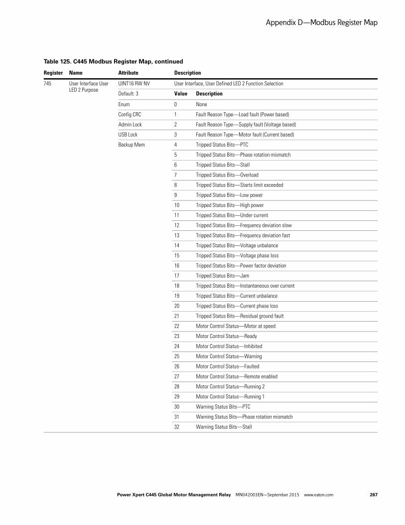
Appendix D—Modbus Register Map
745 User Interface User LED 2 Purpose
UINT16 RW NV User Interface, User Defined LED 2 Function Selection
Default: 3 Value Description
Enum 0 None
Config CRC 1 Fault Reason Type—Load fault (Power based)
Admin Lock 2 Fault Reason Type—Supply fault (Voltage based)
USB Lock 3 Fault Reason Type—Motor fault (Current based)
Backup Mem 4 Tripped Status Bits—PTC
5 Tripped Status Bits—Phase rotation mismatch
6 Tripped Status Bits—Stall
7 Tripped Status Bits—Overload
8 Tripped Status Bits—Starts limit exceeded
9 Tripped Status Bits—Low power
10 Tripped Status Bits—High power
11 Tripped Status Bits—Under current
12 Tripped Status Bits—Frequency deviation slow
13 Tripped Status Bits—Frequency deviation fast
14 Tripped Status Bits—Voltage unbalance
15 Tripped Status Bits—Voltage phase loss
16 Tripped Status Bits—Power factor deviation
17 Tripped Status Bits—Jam
18 Tripped Status Bits—Instantaneous over current
19 Tripped Status Bits—Current unbalance
20 Tripped Status Bits—Current phase loss
21 Tripped Status Bits—Residual ground fault
22 Motor Control Status—Motor at speed
23 Motor Control Status—Ready
24 Motor Control Status—Inhibited
25 Motor Control Status—Warning
26 Motor Control Status—Faulted
27 Motor Control Status—Remote enabled
28 Motor Control Status—Running 2
29 Motor Control Status—Running 1
30 Warning Status Bits—PTC
31 Warning Status Bits—Phase rotation mismatch
32 Warning Status Bits—Stall
Table 125. C445 Modbus Register Map, continued
Register Name Attribute Description
Power Xpert C445 Global Motor Management Relay MN042003EN—September 2015 www.eaton.com 267

Appendix D—Modbus Register Map
745 User Interface User LED 2 Purpose
UINT16 RW NV User Interface, User Defined LED 2 Function Selection, continued
Value Description
33 Warning Status Bits—Overload
34 Warning Status Bits—Starts limit exceeded
35 Warning Status Bits—Low power
36 Warning Status Bits—High power
37 Warning Status Bits—Under current
38 Warning Status Bits—Frequency deviation slow
39 Warning Status Bits—Frequency deviation fast
40 Warning Status Bits—Voltage unbalance
41 Warning Status Bits—Voltage phase loss
42 Warning Status Bits—Power factor deviation
43 Warning Status Bits—Jam
44 Warning Status Bits—Instantaneous over current
45 Warning Status Bits—Current unbalance
46 Warning Status Bits—Current phase loss
47 Warning Status Bits—Residual ground fault
48 Warning Status Bits—External ground fault
49 Warning Status Bits—Over voltage
50 Warning Status Bits—Under voltage
51 Tripped Status Bits—Under voltage
52 Tripped Status Bits—Over voltage
53 Tripped Status Bits—External ground fault
54 Base Control Module Field Output control word—Bit 0
55 Base Control Module Field Output control word—Bit 1
56 Base Control Module Field Output control word—Bit 2
57 Base Control Module Field Output control word—Bit 3
65535 Reserved
Table 125. C445 Modbus Register Map, continued
Register Name Attribute Description
268 Power Xpert C445 Global Motor Management Relay MN042003EN—September 2015 www.eaton.com

Appendix D—Modbus Register Map
746 User Interface User LED 3 Purpose
UINT16 RW NV User Interface, User Defined LED 3 Function Selection
Default: 1 Value Description
Enum 0 None
Config CRC 1 Fault Reason Type—Load fault (Power based)
Admin Lock 2 Fault Reason Type—Supply fault (Voltage based)
USB Lock 3 Fault Reason Type—Motor fault (Current based)
Backup Mem 4 Tripped Status Bits—PTC
5 Tripped Status Bits—Phase rotation mismatch
6 Tripped Status Bits—Stall
7 Tripped Status Bits—Overload
8 Tripped Status Bits—Starts limit exceeded
9 Tripped Status Bits—Low power
10 Tripped Status Bits—High power
11 Tripped Status Bits—Under current
12 Tripped Status Bits—Frequency deviation slow
13 Tripped Status Bits—Frequency deviation fast
14 Tripped Status Bits—Voltage unbalance
15 Tripped Status Bits—Voltage phase loss
16 Tripped Status Bits—Power factor deviation
17 Tripped Status Bits—Jam
18 Tripped Status Bits—Instantaneous over current
19 Tripped Status Bits—Current unbalance
20 Tripped Status Bits—Current phase loss
21 Tripped Status Bits—Residual ground fault
22 Motor Control Status—Motor at speed
23 Motor Control Status—Ready
24 Motor Control Status—Inhibited
25 Motor Control Status—Warning
26 Motor Control Status—Faulted
27 Motor Control Status—Remote enabled
28 Motor Control Status—Running 2
29 Motor Control Status—Running 1
30 Warning Status Bits—PTC
31 Warning Status Bits—Phase rotation mismatch
32 Warning Status Bits—Stall
Table 125. C445 Modbus Register Map, continued
Register Name Attribute Description
Power Xpert C445 Global Motor Management Relay MN042003EN—September 2015 www.eaton.com 269

Appendix D—Modbus Register Map
746 User Interface User LED 3 Purpose
UINT16 RW NV User Interface, User Defined LED 3 Function Selection, continued
Value Description
33 Warning Status Bits—Overload
34 Warning Status Bits—Starts limit exceeded
35 Warning Status Bits—Low power
36 Warning Status Bits—High power
37 Warning Status Bits—Under current
38 Warning Status Bits—Frequency deviation slow
39 Warning Status Bits—Frequency deviation fast
40 Warning Status Bits—Voltage unbalance
41 Warning Status Bits—Voltage phase loss
42 Warning Status Bits—Power factor deviation
43 Warning Status Bits—Jam
44 Warning Status Bits—Instantaneous over current
45 Warning Status Bits—Current unbalance
46 Warning Status Bits—Current phase loss
47 Warning Status Bits—Residual ground fault
48 Warning Status Bits—External ground fault
49 Warning Status Bits—Over voltage
50 Warning Status Bits—Under voltage
51 Tripped Status Bits—Under voltage
52 Tripped Status Bits—Over voltage
53 Tripped Status Bits—External ground fault
54 Base Control Module Field Output control word—Bit 0
55 Base Control Module Field Output control word—Bit 1
56 Base Control Module Field Output control word—Bit 2
57 Base Control Module Field Output control word—Bit 3
65535 Reserved
747 User Interface Button 1 CFG
UINT16 RW NV CFG parameter for the User Interface button 1 function
Default: 1 Value Description
Enum 0 No User Interface button present
Config CRC 1 User Interface button configured as STOP
Admin Lock 2 User Interface button configured as AUTO
USB Lock 3 User Interface button configured as RUN1
Backup Mem 4 User Interface button configured as RUN2
5 User Interface button configured as RESET
Table 125. C445 Modbus Register Map, continued
Register Name Attribute Description
270 Power Xpert C445 Global Motor Management Relay MN042003EN—September 2015 www.eaton.com

Appendix D—Modbus Register Map
748 User Interface Button 2 CFG
UINT16 RW NV CFG parameter for the User Interface button 2 function
Default: 2 Value Description
Enum 0 No User Interface button present
Config CRC 1 User Interface button configured as STOP
Admin Lock 2 User Interface button configured as AUTO
USB Lock 3 User Interface button configured as RUN1
Backup Mem 4 User Interface button configured as RUN2
5 User Interface button configured as RESET
749 User Interface Button 3 CFG
UINT16 RW NV CFG parameter for the User Interface button 3 function
Default: 3 Value Description
Enum 0 No User Interface button present
Config CRC 1 User Interface button configured as STOP
Admin Lock 2 User Interface button configured as AUTO
USB Lock 3 User Interface button configured as RUN1
Backup Mem 4 User Interface button configured as RUN2
5 User Interface button configured as RESET
750 User Interface Button 4 CFG
UINT16 RW NV CFG parameter for the User Interface button 4 function
Default: 4 Value Description
Enum 0 No User Interface button present
Config CRC 1 User Interface button configured as STOP
Admin Lock 2 User Interface button configured as AUTO
USB Lock 3 User Interface button configured as RUN1
Backup Mem 4 User Interface button configured as RUN2
5 User Interface button configured as RESET
751 User Interface Button 5 CFG
UINT16 RW NV CFG parameter for the User Interface button 5 function
Default: 5 Value Description
Enum 0 No User Interface button present
Config CRC 1 User Interface button configured as STOP
Admin Lock 2 User Interface button configured as AUTO
USB Lock 3 User Interface button configured as RUN1
Backup Mem 4 User Interface button configured as RUN2
5 User Interface button configured as RESET
Table 125. C445 Modbus Register Map, continued
Register Name Attribute Description
Power Xpert C445 Global Motor Management Relay MN042003EN—September 2015 www.eaton.com 271

Appendix D—Modbus Register Map
752 User Interface LED 1 color CFG
UINT16 RW NV User Interface LED 1 Color CFG parameter
Default: 3 Value Description
Enum 0 Sets LED color to green
Config CRC 1 Sets LED color to red
Admin Lock 2 Sets LED color to amber
USB Lock 3 Sets LED color to white
Backup Mem
753 User Interface LED 2 color CFG
UINT16 RW NV User Interface LED 2 Color CFG parameter
Default: 3 Value Description
Enum 0 Sets LED color to green
Config CRC 1 Sets LED color to red
Admin Lock 2 Sets LED color to amber
USB Lock 3 Sets LED color to white
Backup Mem
754 User Interface LED 3 color CFG
UINT16 RW NV User Interface LED 3 Color CFG parameter
Default: 3 Value Description
Enum 0 Sets LED color to green
Config CRC 1 Sets LED color to red
Admin Lock 2 Sets LED color to amber
USB Lock 3 Sets LED color to white
Backup Mem
755 User Interface LED 4 color CFG
UINT16 RW NV User Interface LED 4 Color CFG parameter
Default: 3 Value Description
Enum 0 Sets LED color to green
Config CRC 1 Sets LED color to red
Admin Lock 2 Sets LED color to amber
USB Lock 3 Sets LED color to white
Backup Mem
756 User Interface LED 5 color CFG
UINT16 RW NV User Interface LED 5 Color CFG parameter
Default: 1 Value Description
Enum 0 Sets LED color to green
Config CRC 1 Sets LED color to red
Admin Lock 2 Sets LED color to amber
USB Lock 3 Sets LED color to white
Backup Mem
Table 125. C445 Modbus Register Map, continued
Register Name Attribute Description
272 Power Xpert C445 Global Motor Management Relay MN042003EN—September 2015 www.eaton.com

Appendix D—Modbus Register Map
757 User Interface LED 6 color CFG
UINT16 RW NV User Interface LED 6 Color CFG parameter
Default: 1 Value Description
Enum 0 Sets LED color to green
Config CRC 1 Sets LED color to red
Admin Lock 2 Sets LED color to amber
USB Lock
Backup Mem
758 User Interface LED 7 color CFG
UINT16 RW NV User Interface LED 7 Color CFG parameter
Default: 2 Value Description
Enum 0 Sets LED color to green
Config CRC 1 Sets LED color to red
Admin Lock 2 Sets LED color to amber
USB Lock
Backup Mem
759 User Interface User LED 1 color CFG
UINT16 RW NV User Interface, User Defined LED 1 Color Selection
Default: 1 Value Description
Enum 0 Sets LED color to green
1 Sets LED color to red
2 Sets LED color to amber
760 User Interface User LED 2 color CFG
UINT16 RW NV User Interface, User Defined LED 2 Color Selection
Default: 1 Value Description
Enum 0 Sets LED color to green
1 Sets LED color to red
2 Sets LED color to amber
761 User Interface User LED 3 color CFG
UINT16 RW NV User Interface, User Defined LED 3 Color Selection
Default: 1 Value Description
Enum 0 Sets LED color to green
1 Sets LED color to red
2 Sets LED color to amber
900 Motor1 Overload FLA (Nominal Current) Scaled
UINT16 RW NV Motor1 Overload FLA (Nominal Current) Scaled—Scaled Full Load Amperes for the motor from the motor nameplate. If this is an application with a 2 motor profile, this is the first motor. Scaled by parameter “I Scale Factor”Default: 101
Range: 1 to 65535 (RW)
Units: scaled A
Config CRC
Run Lock
Admin Lock
USB Lock
Backup Mem
Table 125. C445 Modbus Register Map, continued
Register Name Attribute Description
Power Xpert C445 Global Motor Management Relay MN042003EN—September 2015 www.eaton.com 273

Appendix D—Modbus Register Map
901 Motor2 Overload FLA (Nominal Current) Scaled
UINT16 RW NV Motor2 Overload FLA (Nominal Current) Scaled—Scaled Full Load Amperes for the motor from the motor nameplate. If this is an application with a 2 motor profile, this is the second motor. Scaled by parameter: “I Scale Factor”Default: 101
Range: 1 to 65535 (RW)
Units: scaled A
Config CRC
Run Lock
Admin Lock
USB Lock
Backup Mem
902 Motor Rated Service Factor
UINT8 RW NV Motor Rated Service Factor
Default: 115
Range: 100 to 255
Units: %
Config CRC
Run Lock
Admin Lock
USB Lock
Backup Mem
903 Motor Rated Voltage UINT16 RW NV Motor Rated Voltage
Default: 480
Range: 100 to 5000
Units: V
Config CRC
Run Lock
Admin Lock
USB Lock
Backup Mem
904 Motor Rated Frequency
UINT16 RW NV Motor Rated Frequency in Hz
Default: 60
Range: 50 to 60
Units: Hz
Config CRC
Run Lock
Admin Lock
USB Lock
Backup Mem
Table 125. C445 Modbus Register Map, continued
Register Name Attribute Description
274 Power Xpert C445 Global Motor Management Relay MN042003EN—September 2015 www.eaton.com
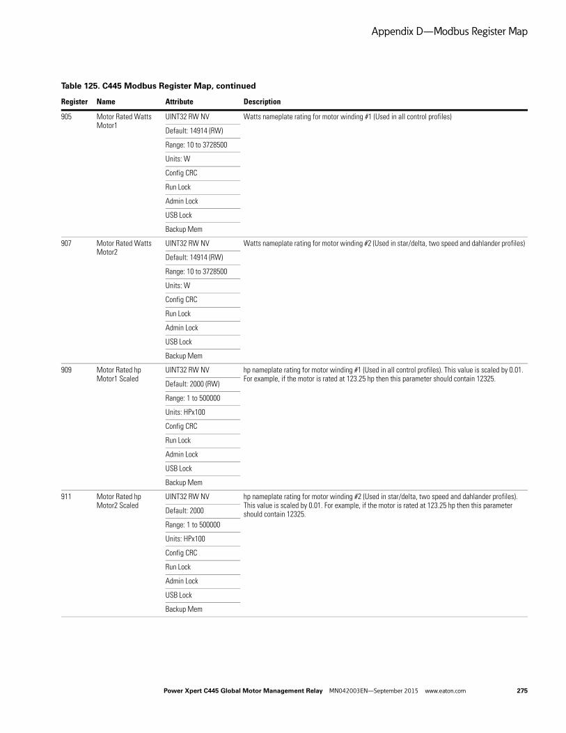
Appendix D—Modbus Register Map
905 Motor Rated Watts Motor1
UINT32 RW NV Watts nameplate rating for motor winding #1 (Used in all control profiles)
Default: 14914 (RW)
Range: 10 to 3728500
Units: W
Config CRC
Run Lock
Admin Lock
USB Lock
Backup Mem
907 Motor Rated Watts Motor2
UINT32 RW NV Watts nameplate rating for motor winding #2 (Used in star/delta, two speed and dahlander profiles)
Default: 14914 (RW)
Range: 10 to 3728500
Units: W
Config CRC
Run Lock
Admin Lock
USB Lock
Backup Mem
909 Motor Rated hp Motor1 Scaled
UINT32 RW NV hp nameplate rating for motor winding #1 (Used in all control profiles). This value is scaled by 0.01. For example, if the motor is rated at 123.25 hp then this parameter should contain 12325.
Default: 2000 (RW)
Range: 1 to 500000
Units: HPx100
Config CRC
Run Lock
Admin Lock
USB Lock
Backup Mem
911 Motor Rated hp Motor2 Scaled
UINT32 RW NV hp nameplate rating for motor winding #2 (Used in star/delta, two speed and dahlander profiles). This value is scaled by 0.01. For example, if the motor is rated at 123.25 hp then this parameter should contain 12325.Default: 2000
Range: 1 to 500000
Units: HPx100
Config CRC
Run Lock
Admin Lock
USB Lock
Backup Mem
Table 125. C445 Modbus Register Map, continued
Register Name Attribute Description
Power Xpert C445 Global Motor Management Relay MN042003EN—September 2015 www.eaton.com 275
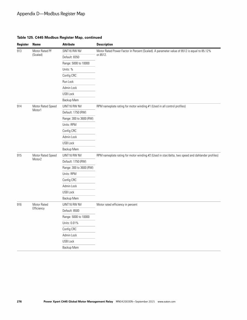
Appendix D—Modbus Register Map
913 Motor Rated PF (Scaled)
SINT16 RW NV Motor Rated Power Factor in Percent (Scaled). A parameter value of 8512 is equal to 85.12% or.8512.
Default: 8350
Range: 5000 to 10000
Units: %
Config CRC
Run Lock
Admin Lock
USB Lock
Backup Mem
914 Motor Rated Speed Motor1
UINT16 RW NV RPM nameplate rating for motor winding #1 (Used in all control profiles)
Default: 1750 (RW)
Range: 300 to 3600 (RW)
Units: RPM
Config CRC
Admin Lock
USB Lock
Backup Mem
915 Motor Rated Speed Motor2
UINT16 RW NV RPM nameplate rating for motor winding #2 (Used in star/delta, two speed and dahlander profiles)
Default: 1750 (RW)
Range: 300 to 3600 (RW)
Units: RPM
Config CRC
Admin Lock
USB Lock
Backup Mem
916 Motor Rated Efficiency
UINT16 RW NV Motor rated efficiency in percent
Default: 8500
Range: 5000 to 10000
Units: 0.01%
Config CRC
Admin Lock
USB Lock
Backup Mem
Table 125. C445 Modbus Register Map, continued
Register Name Attribute Description
276 Power Xpert C445 Global Motor Management Relay MN042003EN—September 2015 www.eaton.com

Appendix D—Modbus Register Map
917 Motor Rated Stator Resistance
UINT16 RW NV Motor Rated Stator Resistance
Default: 280
Units: mOhms
Config CRC
Admin Lock
USB Lock
Backup Mem
918 CT Ratio—Primary UINT16 RW NV CT Ratio—Primary
Default: 1
Config CRC
Run Lock
Admin Lock
USB Lock
Backup Mem
919 CT Ratio—Secondary
UINT16 RW NV CT Ratio—Secondary
Default: 1
Config CRC
Run Lock
Admin Lock
USB Lock
Backup Mem
920 PT Ratio Primary UINT16 RW NV PT Ratio—Primary (Only available with external PT)
Default: 1
Run Lock
921 PT Ratio Secondary UINT16 RW NV PT Ratio—Secondary (Only available with external PT)
Default: 1
Run Lock
Table 125. C445 Modbus Register Map, continued
Register Name Attribute Description
Power Xpert C445 Global Motor Management Relay MN042003EN—September 2015 www.eaton.com 277
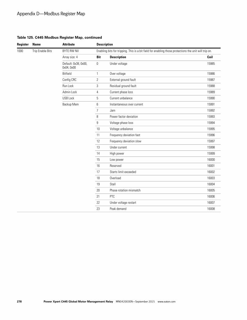
Appendix D—Modbus Register Map
1000 Trip Enable Bits BYTE RW NV Enabling bits for tripping. This is a bit field for enabling those protections the unit will trip on.
Array size: 4 Bit Description Coil
Default: 0x38, 0x00, 0x04, 0x00
0 Under voltage 15985
Bitfield 1 Over voltage 15986
Config CRC 2 External ground fault 15987
Run Lock 3 Residual ground fault 15988
Admin Lock 4 Current phase loss 15989
USB Lock 5 Current unbalance 15990
Backup Mem 6 Instantaneous over current 15991
7 Jam 15992
8 Power factor deviation 15993
9 Voltage phase loss 15994
10 Voltage unbalance 15995
11 Frequency deviation fast 15996
12 Frequency deviation slow 15997
13 Under current 15998
14 High power 15999
15 Low power 16000
16 Reserved 16001
17 Starts limit exceeded 16002
18 Overload 16003
19 Stall 16004
20 Phase rotation mismatch 16005
21 PTC 16006
22 Under voltage restart 16007
23 Peak demand 16008
Table 125. C445 Modbus Register Map, continued
Register Name Attribute Description
278 Power Xpert C445 Global Motor Management Relay MN042003EN—September 2015 www.eaton.com
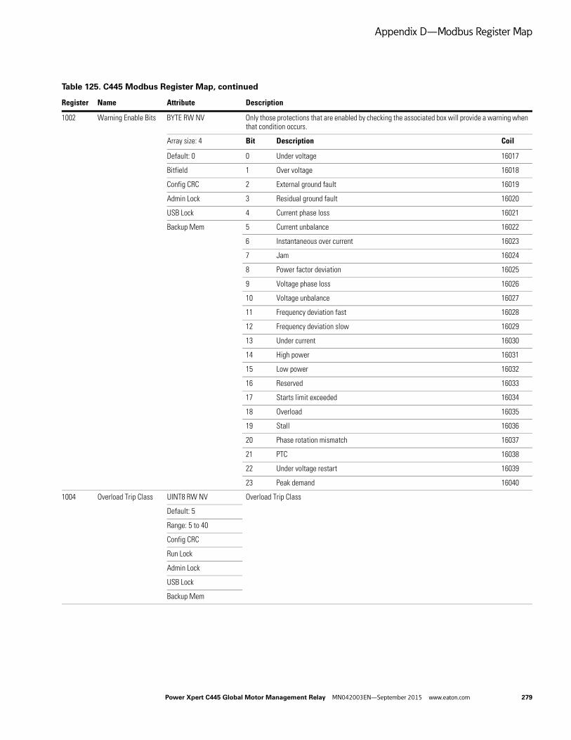
Appendix D—Modbus Register Map
1002 Warning Enable Bits BYTE RW NV Only those protections that are enabled by checking the associated box will provide a warning when that condition occurs.
Array size: 4 Bit Description Coil
Default: 0 0 Under voltage 16017
Bitfield 1 Over voltage 16018
Config CRC 2 External ground fault 16019
Admin Lock 3 Residual ground fault 16020
USB Lock 4 Current phase loss 16021
Backup Mem 5 Current unbalance 16022
6 Instantaneous over current 16023
7 Jam 16024
8 Power factor deviation 16025
9 Voltage phase loss 16026
10 Voltage unbalance 16027
11 Frequency deviation fast 16028
12 Frequency deviation slow 16029
13 Under current 16030
14 High power 16031
15 Low power 16032
16 Reserved 16033
17 Starts limit exceeded 16034
18 Overload 16035
19 Stall 16036
20 Phase rotation mismatch 16037
21 PTC 16038
22 Under voltage restart 16039
23 Peak demand 16040
1004 Overload Trip Class UINT8 RW NV Overload Trip Class
Default: 5
Range: 5 to 40
Config CRC
Run Lock
Admin Lock
USB Lock
Backup Mem
Table 125. C445 Modbus Register Map, continued
Register Name Attribute Description
Power Xpert C445 Global Motor Management Relay MN042003EN—September 2015 www.eaton.com 279
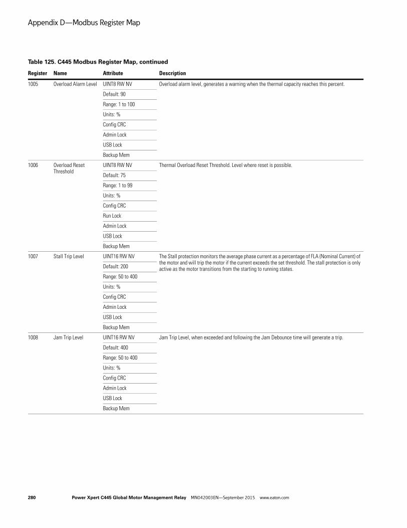
Appendix D—Modbus Register Map
1005 Overload Alarm Level UINT8 RW NV Overload alarm level, generates a warning when the thermal capacity reaches this percent.
Default: 90
Range: 1 to 100
Units: %
Config CRC
Admin Lock
USB Lock
Backup Mem
1006 Overload Reset Threshold
UINT8 RW NV Thermal Overload Reset Threshold. Level where reset is possible.
Default: 75
Range: 1 to 99
Units: %
Config CRC
Run Lock
Admin Lock
USB Lock
Backup Mem
1007 Stall Trip Level UINT16 RW NV The Stall protection monitors the average phase current as a percentage of FLA (Nominal Current) of the motor and will trip the motor if the current exceeds the set threshold. The stall protection is only active as the motor transitions from the starting to running states.Default: 200
Range: 50 to 400
Units: %
Config CRC
Admin Lock
USB Lock
Backup Mem
1008 Jam Trip Level UINT16 RW NV Jam Trip Level, when exceeded and following the Jam Debounce time will generate a trip.
Default: 400
Range: 50 to 400
Units: %
Config CRC
Admin Lock
USB Lock
Backup Mem
Table 125. C445 Modbus Register Map, continued
Register Name Attribute Description
280 Power Xpert C445 Global Motor Management Relay MN042003EN—September 2015 www.eaton.com

Appendix D—Modbus Register Map
1009 Jam Alarm Level UINT16 RW NV Jam Alarm Level, when exceeded and following the Alarm Debounce Time in the Protections/General category, will generate a warning.
Default: 400
Range: 50 to 400
Units: %
Config CRC
Admin Lock
USB Lock
Backup Mem
1010 Jam Debounce UINT16 RW NV Jam Debounce is the time delay following the trip level being exceeded until a trip occurs.
Default: 10
Range: 1 to 60
Units: seconds
Config CRC
Admin Lock
USB Lock
Backup Mem
1011 Allowed Starts Per Hour
UINT16 RW NV The starts protection works by limiting the number of starts per hour. Starting the motor frequently can lead to motor windings overheating resulting in a reduced life of the stator insulation. The user can choose a start limit value as well as disabling the fault. Note that the start limit is only verified when a start command is received.
Default: 4
Range: 1 to 60
Config CRC
Admin Lock
USB Lock
Backup Mem
1012 Instantaneous Overcurrent Trip Level
UINT16 RW NV Instantaneous Overcurrent Trip Level, when exceeded and following the Instantaneous Overcurrent Debounce time will generate a trip.
Default: 400
Range: 50 to 400
Units: %
Config CRC
Admin Lock
USB Lock
Backup Mem
1013 Instantaneous Overcurrent Alarm Level
UINT16 RW NV Instantaneous Overcurrent Alarm Level, when exceeded and following the Alarm Debounce Time in the Protections/General category, will generate a warning.
Default: 400
Range: 50 to 400
Units: %
Config CRC
Admin Lock
USB Lock
Backup Mem
Table 125. C445 Modbus Register Map, continued
Register Name Attribute Description
Power Xpert C445 Global Motor Management Relay MN042003EN—September 2015 www.eaton.com 281

Appendix D—Modbus Register Map
1014 Instantaneous Overcurrent Start Delay
UINT16 RW NV Instantaneous Overcurrent Start Delay is a delay at power up to inhibit raising this trip condition until this time expires. If the condition is no longer present when this time expires, no trip will occur.
Default: 0
Range: 0 to 180
Units: seconds
Config CRC
Admin Lock
USB Lock
Backup Mem
1015 Instantaneous Overcurrent Debounce
UINT16 RW NV Instantaneous Overcurrent Debounce is the time delay following the trip level being exceeded until a trip occurs.
Default: 2000
Range: 1 to 2000
Units: ms
Config CRC
Admin Lock
USB Lock
Backup Mem
1018 I Unbalance Trip Level Percent
UINT8 RW NV Current Unbalance Trip Level Percent, when exceeded and following the I Unbalance Debounce time will generate a trip.
Default: 15
Range: 1 to 60
Units: %
Config CRC
Admin Lock
USB Lock
Backup Mem
1019 I Unbalance Alarm Level Percent
UINT8 RW NV Current Unbalance Alarm Level Percent, when exceeded and after the Alarm Debounce Time in the Protections/General category expires will cause a warning to occur.
Default: 15
Range: 1 to 60
Units: %
Config CRC
Admin Lock
USB Lock
Backup Mem
Table 125. C445 Modbus Register Map, continued
Register Name Attribute Description
282 Power Xpert C445 Global Motor Management Relay MN042003EN—September 2015 www.eaton.com

Appendix D—Modbus Register Map
1020 I Unbalance Debounce
UINT16 RW NV Current Unbalance Debounce is the time delay following the trip level being exceeded until a trip occurs.
Default: 15
Range: 1 to 60
Units: seconds
Config CRC
Admin Lock
USB Lock
Backup Mem
1021 Undercurrent Trip Level
UINT8 RW NV Undercurrent Trip Level protection monitors the three-phase currents and will trip the motor if the measured current drops below the set threshold following the Undercurrent Debounce time.
Default: 50
Range: 10 to 90
Units: %
Config CRC
Admin Lock
USB Lock
Backup Mem
1022 Undercurrent Alarm Level
UINT8 RW NV Undercurrent Alarm Level when exceeded and following the Alarm Debounce Time in the Protections/General category, will generate a warning.
Default: 50
Range: 10 to 90
Units: %
Config CRC
Admin Lock
USB Lock
Backup Mem
1023 Undercurrent Debounce
UINT16 RW NV Undercurrent Debounce is the time delay following the trip level being exceeded until a trip occurs.
Default: 20
Range: 1 to 60
Units: seconds
Config CRC
Admin Lock
USB Lock
Backup Mem
Table 125. C445 Modbus Register Map, continued
Register Name Attribute Description
Power Xpert C445 Global Motor Management Relay MN042003EN—September 2015 www.eaton.com 283

Appendix D—Modbus Register Map
1024 Phase Rotation Protection
UINT8 RW NV Bits 0–2 determine the phase rotation protection. 0=No Fault 1=ABC Rotation 2=ACB Rotation
Default: 0 Value Description
Enum 0 Ignore phase order
Config CRC 1 ABC (L1-L2-L3) phase order
Run Lock 2 ACB (L1-L3-L2) phase order
Admin Lock
USB Lock
Backup Mem
1025 Overvoltage Trip Level
UINT16 RW NV Overvoltage Trip Level, when exceeded and following the Overvoltage Debounce time will generate a trip.
Default: 110
Range: 90 to 150
Units: %
Config CRC
Admin Lock
USB Lock
Backup Mem
1026 Overvoltage Alarm Level
UINT16 RW NV Overvoltage Alarm Level, when exceeded and following the Alarm Debounce Time in the Protections/General category, will generate a warning.
Default: 110
Range: 90 to 150
Units: %
Config CRC
Admin Lock
USB Lock
Backup Mem
1027 Overvoltage Debounce
UINT16 RW NV Overvoltage Debounce is the time delay following the trip level being exceeded until a trip occurs.
Default: 20
Range: 1 to 60
Units: seconds
Config CRC
Admin Lock
USB Lock
Backup Mem
Table 125. C445 Modbus Register Map, continued
Register Name Attribute Description
284 Power Xpert C445 Global Motor Management Relay MN042003EN—September 2015 www.eaton.com

Appendix D—Modbus Register Map
1028 Undervoltage Trip Level
UINT8 RW NV Undervoltage Trip Level protection monitors the three phase voltages and will trip the motor if the measured voltage drops below the set threshold following the Undervoltage Deboune time.
Default: 90
Range: 10 to 100
Units: %
Config CRC
Admin Lock
USB Lock
Backup Mem
1029 Undervoltage Alarm Level
UINT8 RW NV Undervoltage Alarm Level when exceeded and following the Alarm Debounce Time in the Protections/General category, will generate a warning.
Default: 90
Range: 10 to 100
Units: %
Config CRC
Admin Lock
USB Lock
Backup Mem
1030 Undervoltage Start Delay
UINT16 RW NV Undervoltage Start Delay is a delay to prevent this protection, if enabled from tripping the motor at start up until this time expires. If the Undervoltage condition is still present after this time delay, then a trip would occur if this condition were still present following the Undervoltage Debounce time.
Default: 20
Range: 0 to 60
Units: seconds
Config CRC
Admin Lock
USB Lock
Backup Mem
1031 Undervoltage Debounce
UINT16 RW NV Undervoltage Debounce is the time delay following the trip level being exceeded until a trip occurs.
Default: 20
Range: 1 to 60
Units: seconds
Config CRC
Admin Lock
USB Lock
Backup Mem
Table 125. C445 Modbus Register Map, continued
Register Name Attribute Description
Power Xpert C445 Global Motor Management Relay MN042003EN—September 2015 www.eaton.com 285
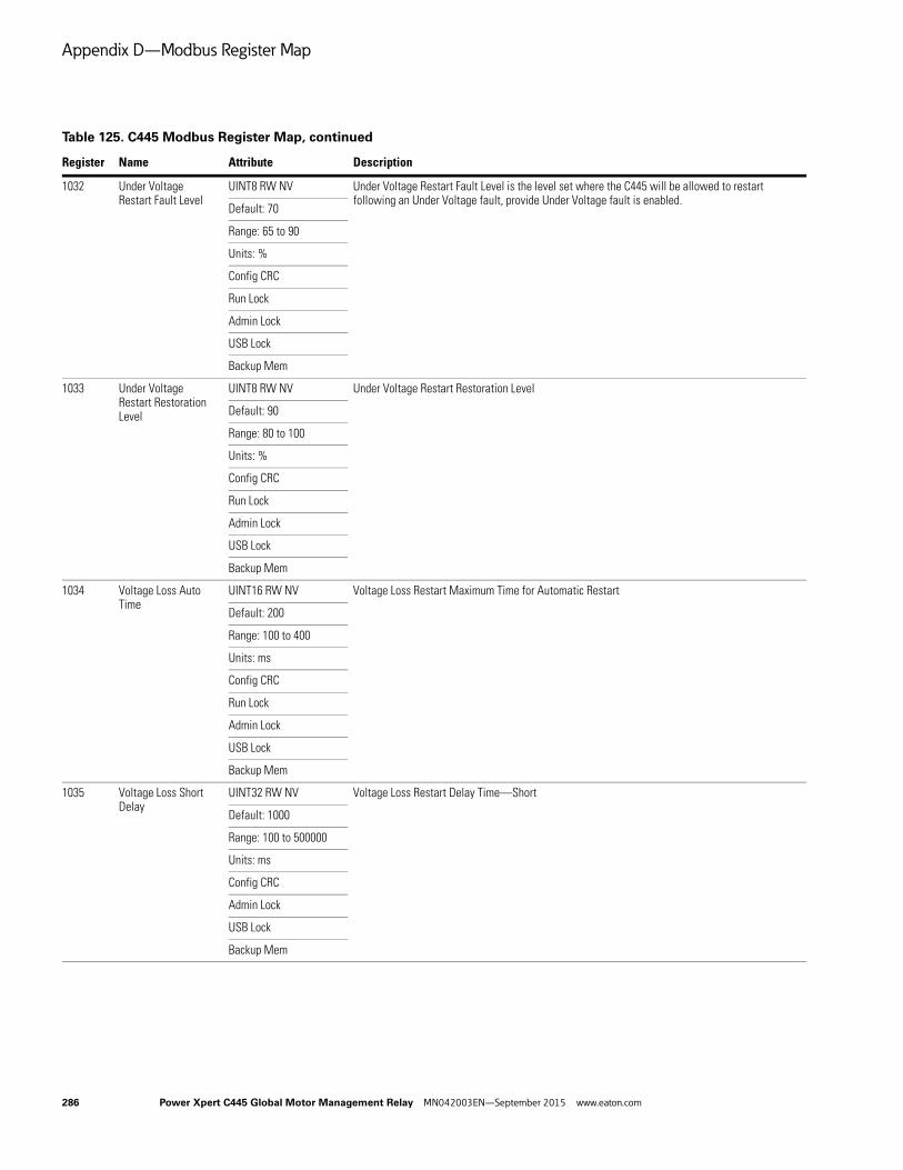
Appendix D—Modbus Register Map
1032 Under Voltage Restart Fault Level
UINT8 RW NV Under Voltage Restart Fault Level is the level set where the C445 will be allowed to restart following an Under Voltage fault, provide Under Voltage fault is enabled.
Default: 70
Range: 65 to 90
Units: %
Config CRC
Run Lock
Admin Lock
USB Lock
Backup Mem
1033 Under Voltage Restart Restoration Level
UINT8 RW NV Under Voltage Restart Restoration Level
Default: 90
Range: 80 to 100
Units: %
Config CRC
Run Lock
Admin Lock
USB Lock
Backup Mem
1034 Voltage Loss Auto Time
UINT16 RW NV Voltage Loss Restart Maximum Time for Automatic Restart
Default: 200
Range: 100 to 400
Units: ms
Config CRC
Run Lock
Admin Lock
USB Lock
Backup Mem
1035 Voltage Loss Short Delay
UINT32 RW NV Voltage Loss Restart Delay Time—Short
Default: 1000
Range: 100 to 500000
Units: ms
Config CRC
Admin Lock
USB Lock
Backup Mem
Table 125. C445 Modbus Register Map, continued
Register Name Attribute Description
286 Power Xpert C445 Global Motor Management Relay MN042003EN—September 2015 www.eaton.com
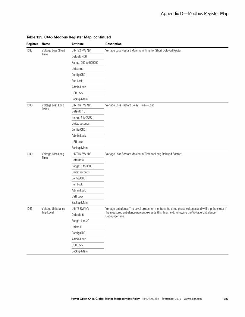
Appendix D—Modbus Register Map
1037 Voltage Loss Short Time
UINT32 RW NV Voltage Loss Restart Maximum Time for Short Delayed Restart
Default: 400
Range: 200 to 500000
Units: ms
Config CRC
Run Lock
Admin Lock
USB Lock
Backup Mem
1039 Voltage Loss Long Delay
UINT16 RW NV Voltage Loss Restart Delay Time—Long
Default: 10
Range: 1 to 3600
Units: seconds
Config CRC
Admin Lock
USB Lock
Backup Mem
1040 Voltage Loss Long Time
UINT16 RW NV Voltage Loss Restart Maximum Time for Long Delayed Restart
Default: 4
Range: 0 to 3600
Units: seconds
Config CRC
Run Lock
Admin Lock
USB Lock
Backup Mem
1043 Voltage Unbalance Trip Level
UINT8 RW NV Voltage Unbalance Trip Level protection monitors the three phase voltages and will trip the motor if the measured unbalance percent exceeds this threshold, following the Voltage Unbalance Debounce time.Default: 6
Range: 1 to 20
Units: %
Config CRC
Admin Lock
USB Lock
Backup Mem
Table 125. C445 Modbus Register Map, continued
Register Name Attribute Description
Power Xpert C445 Global Motor Management Relay MN042003EN—September 2015 www.eaton.com 287

Appendix D—Modbus Register Map
1044 Voltage Unbalance Alarm Level
UINT8 RW NV Voltage Unbalance Alarm Level when exceeded and following the Alarm Debounce Time in the Protections/General category, will generate a warning.
Default: 6
Range: 1 to 20
Units: %
Config CRC
Admin Lock
USB Lock
Backup Mem
1045 Voltage Unbalance Debounce
UINT16 RW NV Voltage Unbalance Debounce is the time delay following the trip level being exceeded until a trip occurs.
Default: 20
Range: 1 to 60
Units: seconds
Config CRC
Admin Lock
USB Lock
Backup Mem
1046 High kW Trip Level SINT16 RW NV High kW Trip Level protection will trip the motor if the calculated High kW Trip Level exceeds this threshold, following the Voltage Unbalance Debounce time.
Default: 110
Range: -200 to 200
Units: %
Config CRC
Admin Lock
USB Lock
Backup Mem
1047 High kW Alarm Level SINT16 RW NV High kW Alarm Level when exceeded and following the Alarm Debounce Time in the Protections/General category, will generate a warning.
Default: 110
Range: -200 to 200
Units: %
Config CRC
Admin Lock
USB Lock
Backup Mem
Table 125. C445 Modbus Register Map, continued
Register Name Attribute Description
288 Power Xpert C445 Global Motor Management Relay MN042003EN—September 2015 www.eaton.com

Appendix D—Modbus Register Map
1048 High kW Debounce UINT16 RW NV High kW Debounce is the time delay following the trip level being exceeded until a trip occurs.
Default: 20
Range: 1 to 60
Units: seconds
Config CRC
Admin Lock
USB Lock
Backup Mem
1049 Low kW Trip Level SINT16 RW NV Low kW Trip Level protection will trip the motor if the calculated Low kW Trip Level exceeds this threshold, following the Voltage Unbalance Debounce time.
Default: 50
Range: -200 to 200
Units: %
Config CRC
Admin Lock
USB Lock
Backup Mem
1050 Low kW Alarm Level SINT16 RW NV Low kW Alarm Level when exceeded and following the Alarm Debounce Time in the Protections/General category, will generate a warning.
Default: 50
Range: -200 to 200
Units: %
Config CRC
Admin Lock
USB Lock
Backup Mem
1051 Low kW Debounce UINT16 RW NV Low kW Debounce is the time delay following the trip level being exceeded until a trip occurs.
Default: 20
Range: 1 to 60
Units: seconds
Config CRC
Admin Lock
USB Lock
Backup Mem
1052 Peak Demand Warning Threshold
UINT32 RW NV Generate an alarm if the peak demand exceeds this threshold.
Default: 0
Units: W
Config CRC
Admin Lock
USB Lock
Backup Mem
Table 125. C445 Modbus Register Map, continued
Register Name Attribute Description
Power Xpert C445 Global Motor Management Relay MN042003EN—September 2015 www.eaton.com 289

Appendix D—Modbus Register Map
1054 Demand Window Duration
UINT16 RW NV Demand Window Duration
Default: 15
Range: 1 to 240
Units: minutes
Config CRC
Admin Lock
USB Lock
Backup Mem
1055 Power Factor Deviation Trip Level High
SINT16 RW NV PF Deviation Trip Level High—The Power Factor Deviation protection monitors the PF (supply side) of the load and will trip the motor if the measured deviation from rated exceeds the set threshold. The high power factor protection is active when the motor is in the running state.Default: 10000
Range: –10000 to 10000
Units: %
Config CRC
Admin Lock
USB Lock
Backup Mem
1056 Power Factor Deviation Trip Level Low
SINT16 RW NV PF Deviation Trip Level—The Power Factor Deviation protection monitors the PF (supply side) of the load and will trip the motor if the measured deviation from rated exceeds the set threshold.
Default: 0
Range: –10000 to 10000
Units: %
Config CRC
Admin Lock
USB Lock
Backup Mem
1057 Power Factor Deviation Alarm Level High
SINT16 RW NV Power Factor Deviation Alarm Level High—If the Power Factor rises above this level, following the Alarm Debounce Time in the Protections/General category, a warning is generated.
Default: 10000
Range: –10000 to 10000
Units: %
Config CRC
Admin Lock
USB Lock
Backup Mem
Table 125. C445 Modbus Register Map, continued
Register Name Attribute Description
290 Power Xpert C445 Global Motor Management Relay MN042003EN—September 2015 www.eaton.com
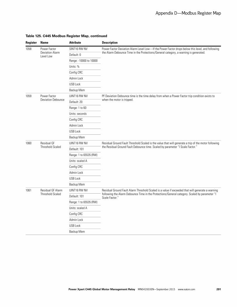
Appendix D—Modbus Register Map
1058 Power Factor Deviation Alarm Level Low
SINT16 RW NV Power Factor Deviation Alarm Level Low—If the Power Factor drops below this level, and following the Alarm Debounce Time in the Protections/General category, a warning is generated.
Default: 0
Range: -10000 to 10000
Units: %
Config CRC
Admin Lock
USB Lock
Backup Mem
1059 Power Factor Deviation Debounce
UINT16 RW NV PF Deviation Debounce time is the time delay from when a Power Factor trip condition exists to when the motor is tripped.
Default: 20
Range: 1 to 60
Units: seconds
Config CRC
Admin Lock
USB Lock
Backup Mem
1060 Residual GF Threshold Scaled
UINT16 RW NV Residual Ground Fault Threshold Scaled is the value that will generate a trip of the motor following the Residual Ground Fault Debounce time. Scaled by parameter “I Scale Factor.”
Default: 101
Range: 1 to 65535 (RW)
Units: scaled A
Config CRC
Admin Lock
USB Lock
Backup Mem
1061 Residual GF Alarm Threshold Scaled
UINT16 RW NV Residual Ground Fault Alarm Threshold Scaled is a value if exceeded that will generate a warning following the Alarm Debounce Time in the Protections/General category. Scaled by parameter “I Scale Factor.”Default: 101
Range: 1 to 65535 (RW)
Units: scaled A
Config CRC
Admin Lock
USB Lock
Backup Mem
Table 125. C445 Modbus Register Map, continued
Register Name Attribute Description
Power Xpert C445 Global Motor Management Relay MN042003EN—September 2015 www.eaton.com 291

Appendix D—Modbus Register Map
1062 Residual GF Start Delay
UINT16 RW NV Residual Ground Fault Start Delay is a delay at power up to inhibit raising a ground fault trip condition until this time expires. If the ground fault trip condition is no longer present when this time expires, no trip will occur.Default: 0
Range: 0 to 5000
Units: ms
Config CRC
Admin Lock
USB Lock
Backup Mem
1063 Residual GF Debounce
UINT16 RW NV Residual Ground Fault Debounce is the time delay before a trip occurs
Default: 5
Range: 1 to 60
Units: seconds
Config CRC
Admin Lock
USB Lock
Backup Mem
1064 Residual GF Use Inhibit Current
BOOL RW NV Residual Ground Fault Use Inhibit Current, if selected the Residual GF Inhibit Current will be used.
Default: FALSE
Config CRC
Admin Lock
USB Lock
Backup Mem
1065 Residual GF Inhibit Current Percent
UINT16 RW NV This parameter will inhibit a Ground Fault trip if the Ground Fault current exceeds this percentage. The purpose of this is to allow an upstream control to resolve the issue.
Default: 50
Range: 25 to 100
Units: %
Config CRC
Admin Lock
USB Lock
1066 Frequency Deviation Fast Trip Level Scaled
UINT16 RW NV Frequency Deviation Fast Trip Level has a small range for the trip level selection with a large time delay to trip range. If the frequency deviation from rated exceeds the set threshold for the duration of the Frequency Deviation Fast Debounce time, it will trip the motor. The frequency deviation protection is active when the motor is in the energized state. This parameter is scaled by 0.01%.
Default: 10
Range: 2 to 200
Units: 0.01 Hz
Config CRC
Admin Lock
USB Lock
Backup Mem
Table 125. C445 Modbus Register Map, continued
Register Name Attribute Description
292 Power Xpert C445 Global Motor Management Relay MN042003EN—September 2015 www.eaton.com
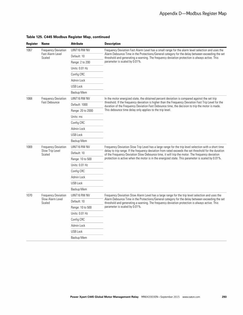
Appendix D—Modbus Register Map
1067 Frequency Deviation Fast Alarm Level Scaled
UINT16 RW NV Frequency Deviation Fast Alarm Level has a small range for the alarm level selection and uses the Alarm Debounce Time in the Protections/General category for the delay between exceeding the set threshold and generating a warning. The frequency deviation protection is always active. This parameter is scaled by 0.01%.
Default: 10
Range: 2 to 200
Units: 0.01 Hz
Config CRC
Admin Lock
USB Lock
Backup Mem
1068 Frequency Deviation Fast Debounce
UINT16 RW NV In the motor energized state, the obtained percent deviation is compared against the set trip threshold. If the frequency deviation is higher than the Frequency Deviation Fast Trip Level for the duration of the Frequency Deviation Fast Debounce time, the decision to trip the motor is made. This debounce time delay only applies to the trip level.
Default: 1000
Range: 20 to 2000
Units: ms
Config CRC
Admin Lock
USB Lock
Backup Mem
1069 Frequency Deviation Slow Trip Level Scaled
UINT16 RW NV Frequency Deviation Slow Trip Level has a large range for the trip level selection with a short time delay to trip range. If the frequency deviation from rated exceeds the set threshold for the duration of the Frequency Deviation Slow Debounce time, it will trip the motor. The frequency deviation protection is active when the motor is in the energized state. This parameter is scaled by 0.01%.
Default: 10
Range: 10 to 500
Units: 0.01 Hz
Config CRC
Admin Lock
USB Lock
Backup Mem
1070 Frequency Deviation Slow Alarm Level Scaled
UINT16 RW NV Frequency Deviation Slow Alarm Level has a large range for the trip level selection and uses the Alarm Debounce Time in the Protections/General category for the delay between exceeding the set threshold and generating a warning. The frequency deviation protection is always active. This parameter is scaled by 0.01%.
Default: 10
Range: 10 to 500
Units: 0.01 Hz
Config CRC
Admin Lock
USB Lock
Backup Mem
Table 125. C445 Modbus Register Map, continued
Register Name Attribute Description
Power Xpert C445 Global Motor Management Relay MN042003EN—September 2015 www.eaton.com 293

Appendix D—Modbus Register Map
1071 Frequency Deviation Slow Debounce
UINT16 RW NV In the motor energized state, the obtained percent deviation is compared against the set trip threshold. If the frequency deviation is higher than the Frequency Deviation Slow Trip Level for the duration of the Frequency Deviation Slow Debounce time, the decision to trip the motor is made. This debounce time delay only applies to the trip level.
Default: 20
Range: 1 to 60
Units: seconds
Config CRC
Admin Lock
USB Lock
Backup Mem
1072 Global Auto Reset Enable
BOOL RW NV If disabled, no auto reset; if enabled, auto reset is based on trip auto-reset bit selections
Default: FALSE
Config CRC
Run Lock
Admin Lock
USB Lock
Backup Mem
1073 Trip Auto Reset Enable Bits
BYTE RW NV Trip Auto Reset Enable Bits select the protections that are to auto-reset.
Array size: 4 Bit Description Coil
Default: 0 0 Under voltage 17153
Bitfield 1 Over voltage 17154
Config CRC 2 External ground fault 17155
Run Lock 3 Residual ground fault 17156
Admin Lock 4 Current phase loss 17157
USB Lock 5 Current unbalance 17158
Backup Mem 6 Instantaneous over current 17159
7 Jam 17160
8 Power factor deviation 17161
9 Voltage phase loss 17162
10 Voltage unbalance 17163
11 Frequency deviation fast 17164
12 Frequency deviation slow 17165
13 Under current 17166
14 High power 17167
15 Low power 17168
16 Reserved 17169
17 Starts limit exceeded 17170
Table 125. C445 Modbus Register Map, continued
Register Name Attribute Description
294 Power Xpert C445 Global Motor Management Relay MN042003EN—September 2015 www.eaton.com

Appendix D—Modbus Register Map
1073 Trip Auto Reset Enable Bits
BYTE RW NV Trip Auto Reset Enable Bits select the protections that are to auto-reset, continued
Bit Description Coil
18 Overload 17171
19 Stall 17172
20 Phase rotation mismatch 17173
21 PTC 17174
22 Under voltage restart 17175
23 Peak demand 17176
1075 Auto Reset Delay UINT16 RW NV The time delay following a fault before attempting to auto-reset that fault condition
Default: 180
Range: 0 to 3600
Units: seconds
Config CRC
Run Lock
Admin Lock
USB Lock
Backup Mem
1076 Fault Reset on Power Up
BOOL RW NV If enabled, perform a fault reset on power up
Default: FALSE
Config CRC
Admin Lock
USB Lock
Backup Mem
1077 Backspin Inhibit Time UINT16 RW NV Anti-backspin inhibit time before a reset is allowed
Default: 0
Range: 0 to 3600
Units: seconds
Config CRC
Admin Lock
USB Lock
Backup Mem
Table 125. C445 Modbus Register Map, continued
Register Name Attribute Description
Power Xpert C445 Global Motor Management Relay MN042003EN—September 2015 www.eaton.com 295

Appendix D—Modbus Register Map
1078 Motor State Transition to run delay from Start
UINT16 RW NV If the motor is instructed to run by the user, but the current thresholds are not reached, the C445 will not fault on Undercurrent if that protection is enabled because it has not realized a run state. If the user wants the unit to fault under these conditions on an enabled protection following the selected debounce time for that protection, a time must be selected for this parameter. The default is 10 seconds.
Default: 10
Range: 2 to 360
Units: seconds
Config CRC
Run Lock
Admin Lock
USB Lock
Backup Mem
1079 Alarm Debounce Time
UINT16 RW NV Alarm Debounce Time—applies to all protection functions
Default: 2000
Range: 200 to 5000
Units: ms
Config CRC
Admin Lock
USB Lock
Backup Mem
1080 If Protection Start Inhibit Enable
BOOL RW NV If this parameter is enabled and a supply problem exists when the start command is issued, the C445 will be inhibited from starting the motor. This applies to Over Voltage, Under Voltage and Voltage Imbalance.Default: 1
Config CRC
Run Lock
Admin Lock
USB Lock
Backup Mem
1081 Undervoltage Start Inhibit Threshold
UINT8 RW NV If Protection Start Inhibit Enable is enabled, this Under Voltage threshold value is used to inhibit the motor from being started.
Default: 90
Range: 10 to 100
Config CRC
Admin Lock
USB Lock
Backup Mem
1082 Voltage Unbalance Start Inhibit Threshold
UINT8 RW NV If Protection Start Inhibit Enable is enabled, this Voltage Unbalance threshold value is used to inhibit the motor from being started.
Default: 6
Range: 1 to 20
Units: %
Config CRC
Admin Lock
USB Lock
Backup Mem
Table 125. C445 Modbus Register Map, continued
Register Name Attribute Description
296 Power Xpert C445 Global Motor Management Relay MN042003EN—September 2015 www.eaton.com
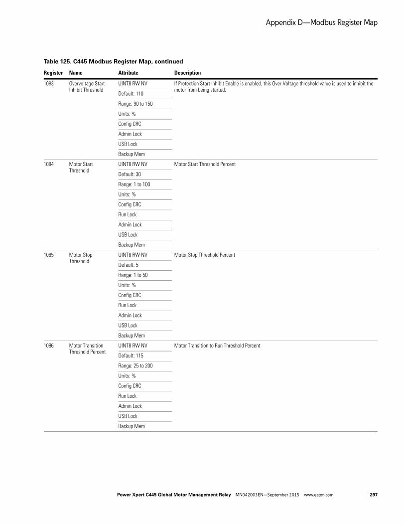
Appendix D—Modbus Register Map
1083 Overvoltage Start Inhibit Threshold
UINT8 RW NV If Protection Start Inhibit Enable is enabled, this Over Voltage threshold value is used to inhibit the motor from being started.
Default: 110
Range: 90 to 150
Units: %
Config CRC
Admin Lock
USB Lock
Backup Mem
1084 Motor Start Threshold
UINT8 RW NV Motor Start Threshold Percent
Default: 30
Range: 1 to 100
Units: %
Config CRC
Run Lock
Admin Lock
USB Lock
Backup Mem
1085 Motor Stop Threshold
UINT8 RW NV Motor Stop Threshold Percent
Default: 5
Range: 1 to 50
Units: %
Config CRC
Run Lock
Admin Lock
USB Lock
Backup Mem
1086 Motor Transition Threshold Percent
UINT8 RW NV Motor Transition to Run Threshold Percent
Default: 115
Range: 25 to 200
Units: %
Config CRC
Run Lock
Admin Lock
USB Lock
Backup Mem
Table 125. C445 Modbus Register Map, continued
Register Name Attribute Description
Power Xpert C445 Global Motor Management Relay MN042003EN—September 2015 www.eaton.com 297

Appendix D—Modbus Register Map
1200 Fault Queue—Event Order
UINT16 RO A List of the Last 10 Faults Shown in the Order They Occurred. Duplicates are allowed and the most recent is at the top.
Array size: 10 Value Description
Enum 0 No Faults
1 Under voltage
2 Over voltage
3 External GF
4 Residual GF
5 Current phase loss
6 Current unbalance
7 Instantaneous over current
8 Jam
9 PF Deviation
10 Voltage phase loss
11 Voltage unbalance
12 Frequency deviation fast
13 Frequency deviation slow
14 Under current
15 High power
16 Low power
17 Contactor failure
18 Starts limit exceeded
19 Overload
20 Stall
21 Phase rotation mismatch
22 PTC—See PTC State for details
23 Under voltage restart
24 Measurement Module fault
25 Communication loss on active fieldbus
26 Measurement Module not available or communication loss with the module
27 User Interface not available or communication loss with the module
28 Test trip was triggered
29 Option Card not available or communication loss with the module
30 RTC / Backup Memory Option Board NV memory fail
31 Currently connected User Interface does not match with what was connected before
32 Currently connected Measurement Module does not match with what was connected before
33 Currently connected Option Card does not match with what was connected before
34 Measurement Module firmware is incompatible
Table 125. C445 Modbus Register Map, continued
Register Name Attribute Description
298 Power Xpert C445 Global Motor Management Relay MN042003EN—September 2015 www.eaton.com

Appendix D—Modbus Register Map
1200 Fault Queue—Event Order
UINT16 RO A List of the Last 10 Faults, continued
Value Description
35 User Interface firmware is incompatible
36 Ethernet Option Card firmware is incompatible
37 Profi Option Card firmware is incompatible
500 Internal—communication loss with Power Supply Board
501 Internal—Power Supply Board is not responding to SPI
502 Internal—Checksums in NV memory (FRAM) didn't match during read (neither pair)
503 Internal—Checksums in NV memory (FRAM) didn't match during write (neither pair)
504 Internal—RTC / Backup Memory Option Card is missing
505 Internal—RTC / Backup Memory Option Card does not match actual
506 Internal—RTC / Backup Memory Option Card has NV Fault.
507 Internal—serial flash memory fault (Attempt Factory Reset first. Return to manufacturer if not cleared)
508 Internal—logic mapping error (Attempt factory reset)
1300 Fault Snap Shot Log Year
UINT16 RO Fault Snap Shot Log Year
Default: 0
Backup Mem
1301 Fault Snap Shot Log Month
UINT8 RO Fault Snap Shot Log Month
Default: 0
Backup Mem
1302 Fault Snap Shot Log Day
UINT8 RO Fault Snap Shot Log Day
Default: 0
Backup Mem
1303 Fault Snap Shot Log Hour
UINT8 RO Fault Snap Shot Log Hour
Default: 0
Backup Mem
1304 Fault Snap Shot Log Minute
UINT8 RO Fault Snap Shot Log Minute
Default: 0
Backup Mem
1305 Fault Snap Shot Log Second
UINT8 RO Fault Snap Shot Log Second
Default: 0
Backup Mem
Table 125. C445 Modbus Register Map, continued
Register Name Attribute Description
Power Xpert C445 Global Motor Management Relay MN042003EN—September 2015 www.eaton.com 299

Appendix D—Modbus Register Map
1306 Fault Snap Shot Trip Reason
UINT16 RO The fault that caused the trip
Default: 0 Value Description
Enum 0 No Faults
Backup Mem 1 Under voltage
2 Over voltage
3 External GF
4 Residual GF
5 Current phase loss
6 Current unbalance
7 Instantaneous over current
8 Jam
9 PF Deviation
10 Voltage phase loss
11 Voltage unbalance
12 Frequency deviation fast
13 Frequency deviation slow
14 Under current
15 High power
16 Low power
17 Contactor failure
18 Starts limit exceeded
19 Overload
20 Stall
21 Phase rotation mismatch
22 PTC—See PTC State for details
23 Under voltage restart
24 Measurement Module fault
25 Communication loss on active fieldbus
26 Measurement Module not available or communication loss with the module
27 User Interface not available or communication loss with the module
28 Test trip was triggered
29 Option Card not available or communication loss with the module
30 RTC / Backup Memory Option Board NV memory fail
31 Currently connected User Interface does not match with what was connected before
32 Currently connected Measurement Module does not match with what was connected before
Table 125. C445 Modbus Register Map, continued
Register Name Attribute Description
300 Power Xpert C445 Global Motor Management Relay MN042003EN—September 2015 www.eaton.com

Appendix D—Modbus Register Map
1306 Fault Snap Shot Trip Reason
UINT16 RO The fault that caused the trip, continued
Value Description
33 Currently connected Option Card does not match with what was connected before
34 Measurement Module firmware is incompatible
35 User Interface firmware is incompatible
36 Ethernet Option Card firmware is incompatible
37 Profi Option Card firmware is incompatible
500 Internal—communication loss with Power Supply Board
501 Internal—Power Supply Board is not responding to SPI
502 Internal—Checksums in NV memory (FRAM) didn't match during read (neither pair)
503 Internal—Checksums in NV memory (FRAM) didn't match during write (neither pair)
504 Internal—RTC / Backup Memory Option Card is missing
505 Internal—RTC / Backup Memory Option Card does not match actual
506 Internal—RTC / Backup Memory Option Card has NV Fault.
507 Internal—serial flash memory fault (Attempt Factory Reset first. Return to manufacturer if not cleared)
508 Internal—logic mapping error (Attempt factory reset)
1307 Snap Shot Thermal Memory
UINT8 RO Overload Thermal Memory Percent at time of trip
Default: 0
Backup Mem
1308 Snap Shot Phase A (L1) Current Scaled
UINT16 RO Phase A (L1) RMS current at time of trip. Scaled by parameter “I Scale Factor.”
Default: 0
Units: scaled A
Backup Mem
1309 Snap Shot Phase B (L2) Current Scaled
UINT16 RO Phase B (L2) RMS current at time of trip. Scaled by parameter “I Scale Factor.”
Default: 0
Units: scaled A
Backup Mem
1310 Snap Shot Phase C (L3) Current Scaled
UINT16 RO Phase C (L3) RMS current at time of trip. Scaled by parameter “I Scale Factor.”
Default: 0
Units: scaled A
Backup Mem
1311 Snap Shot Voltage AB (L1-L2)
UINT16 RO Voltage AB (L1-L2) RMS volts at time of trip
Default: 0
Units: V
Backup Mem
Table 125. C445 Modbus Register Map, continued
Register Name Attribute Description
Power Xpert C445 Global Motor Management Relay MN042003EN—September 2015 www.eaton.com 301

Appendix D—Modbus Register Map
1312 Snap Shot Voltage BC (L2-L3)
UINT16 RO Voltage BC (L2-L3) RMS volts at time of trip
Default: 0
Units: V
Backup Mem
1313 Snap Shot Voltage CA (L3-L1)
UINT16 RO Voltage CA (L3-L1) RMS volts at time of trip
Default: 0
Units: V
Backup Mem
1314 Snap Shot Frequency Scaled
UINT16 RO Line Frequency at time of trip scaled by 0.01 Hz
Default: 0
Units: 0.01 Hz
Backup Mem
1315 Snap Shot Watts SINT32 RO Real Power at time of trip
Default: 0
Units: W
Backup Mem
1317 Snap Shot VA SINT32 RO Apparent Power at time of trip
Default: 0
Units: VA
Backup Mem
1319 Snap Shot Power Factor Scaled
SINT16 RO Power Factor at time of trip scaled by 0.01%
Default: 0
Units: 0.01%
Backup Mem
1320 Snap Shot Ground Current
UINT16 RO Ground Fault Current RMS at time of trip (See motor current scale factor for scaling)
Default: 0
Units: scaled A
Backup Mem
3000 Modbus Scan Data UINT16 RW Data used for Modbus Scan List
Array size: 32 Array of 32 registers
3032 Modbus Scan List UINT16 RW NV The Modbus scan registers can be used to create custom Modbus interface ranges. This allows various non-contiguous Register Numbers to be entered in this list and be read or written with a single modbus command. The Modbus addresses for this block of data is the “Modbus Scan Data” registers.
Array size: 32 Array of 32 registers
Default: 0
Config CRC
Admin Lock
USB Lock
Backup Mem
Table 125. C445 Modbus Register Map, continued
Register Name Attribute Description
302 Power Xpert C445 Global Motor Management Relay MN042003EN—September 2015 www.eaton.com

Appendix D—Modbus Register Map
4000 RTC Time UINT8 RO Real Time Clock Time in hh:mm:ss format (24 hour format)
Array size: 3 Array of 2 registers
4002 RTC Year UINT16 RW Real Time Clock—year
Range: 2000 to 2099
4003 RTC Month UINT8 RW Real Time Clock Month
Enum Value Description
1 January
2 February
3 March
4 April
5 May
6 June
7 July
8 August
9 September
10 October
11 November
12 December
4004 RTC Day of Month UINT8 RW Real Time Clock Day of Month
4005 RTC Time hours UINT8 RW Real Time Clock Time hours
4006 RTC Time minutes UINT8 RW Real Time Clock Time minutes
4007 RTC Time seconds UINT8 RW Real Time Clock Time seconds
4008 RTC Time (milliseconds)
UINT16 RO Real Time Clock Time milliseconds
4009 RTC Power Interrupted
UINT8 RO Real Time Clock backup power has been interrupted
Default: 0 Value Description
Enum 0 Power not interrupted
Backup Mem 1 Power interrupted
4010 RTC Time In UNIX format
UINT32 RO Real Time Clock time in seconds from UNIX epoch
Units: seconds
4012 RTC Status UINT8 RO Real Time Clock Status Enum
Enum Value Description
0 Running
1 Initializing
2 Real time clock not present
3 Internal error
Table 125. C445 Modbus Register Map, continued
Register Name Attribute Description
Power Xpert C445 Global Motor Management Relay MN042003EN—September 2015 www.eaton.com 303

Appendix D—Modbus Register Map
4013 RTC Time Set Status UINT8 RO Real Time Clock Time Set Status: 0 = Initial Value, 1 = Successful, 2 = In Progress, 3 = Wrong Input, 4 = Conversion out of range, 5 = Internal Error
Enum Value Description
0 Initial value
1 Successful
2 Set in progress
3 Wrong data
4 Conversion out of range
5 Internal error
4014 RTC Time Zone DST Setting Status
UINT8 RO Real Time Clock Time Zone DST Setting Status
Enum Value Description
Config CRC 0 Okay
Admin Lock 1 Manual rule error
USB Lock 2 Time zone error
3 Conversion out of range
4 Internal error
4015 RTC DST Rule UINT8 RW NV Real Time Clock DST Rule Selection
Default: 0 Value Description
Enum 0 No daylight savings time
Config CRC 1 Manually set DST start and end
Admin Lock 2 Europe
USB Lock 3 United States of America
Backup Mem 4 Australia
5 Brazil
6 New Zealand
7 United States before 2007
4016 RTC Manual DST Rule End
UINT8 RW NV Real Time Clock Manual Daylight Savings Time Rule End date/time (month, week, weekday, hour, minute)
Array size: 5 Array of 3 registers
Default: 11, 1, 7, 2, 0
Config CRC
Admin Lock
USB Lock
Backup Mem
Table 125. C445 Modbus Register Map, continued
Register Name Attribute Description
304 Power Xpert C445 Global Motor Management Relay MN042003EN—September 2015 www.eaton.com

Appendix D—Modbus Register Map
4019 RTC Manual DST Rule Start
UINT8 RW NV Real Time Clock Manual Daylight Savings Time Rule Start date/time (month, week, weekday, hour, minute)
Array size: 5 Array of 3 registers
Default: 3, 2, 7, 2, 0
Config CRC
Admin Lock
USB Lock
Backup Mem
4022 RTC Month and Date UINT8 RO Real Time Clock Month and Date
Array size: 2 Array of 1 registers
4023 RTC Time Zone Ahead of UTC
UINT8 RW NV Real Time Clock calculation for Time Zone ahead of UTC. If true, UTC+hh:mm; otherwise UTC-hh:mm
Default: 0 Value Description
Enum 0 UTC –hh: mm
Config CRC 1 UTC + hh: mm
Admin Lock
USB Lock
Backup Mem
4024 RTC Time Zonehh mm
UINT8 RW NV Time zone assignment (UTC+/–hh:mm). Where 0xhhmm. Element [0] = Minutes Element [1] = Hours
Array size: 2 Array of 1 registers
Default: 0
Config CRC
Admin Lock
USB Lock
Backup Mem
5000 Set Admin Password UINT32 RW Set administrator password (0x00000000 means no password)
Default: 0x00000000
Config CRC
Admin Lock
USB Lock
Backup Mem
5002 Administrator Login UINT32 RW Log in with administrator password
5004 Set USB Port Password
UINT32 RW Set USB port password (0x00000000 means no password)
Default: 0x00000000
Config CRC
Admin Lock
USB Lock
Backup Mem
5006 USB Login UINT32 RW Log in with USB Port administrator password
Table 125. C445 Modbus Register Map, continued
Register Name Attribute Description
Power Xpert C445 Global Motor Management Relay MN042003EN—September 2015 www.eaton.com 305

Appendix D—Modbus Register Map
5008 Motor Run Parameter Lock Override
BOOL RW NV When the motor is either running or is being commanded to run certain protection and control parameters are locked. To disable this lock and allow parameters to be adjusted during motor run time, set this parameter to 1. To restrict access during run time, set this parameter to 0.Default: 0
Config CRC
Admin Lock
USB Lock
Backup Mem
6000 Base Control Module Modbus Port Address
UINT8 RW NV Modbus Address for the Base Control Module’s port. The address is loaded at startup. A power cycle is required for change in address to take effect.
Default: 1
Range: 1 to 247
Config CRC
Admin Lock
USB Lock
Backup Mem
6001 Base Control Module Modbus port Baud Rate
UINT8 RW NV Selects the Modbus Baud Rate for the Base Control Module’s Modbus port. A power cycle is required for change in baud rate to take effect.
Default: 0 Value Description
Enum 0 19200
Config CRC 1 9600
Admin Lock 2 38400
USB Lock 3 57600
Backup Mem 4 115200
6002 Base Control Module Modbus port Parity and Stop Bits
UINT8 RW NV Selects the Modbus Parity and Stop Bits for the Base Control Module’s Modbus port. A power cycle is required for change to take effect. Note MODBUS_PARITY_NONE_1_STOP_BIT is not valid when in MODBUS_ASCII_TX_MODE mode.
Default: 0 Value Description
Enum 0 Even parity—1 Stop bit
Config CRC 1 Odd parity—1 Stop bit
Admin Lock 2 No parity—2 Stop bits
USB Lock 3 Even parity—2 Stop bits
Backup Mem 4 Odd parity—2 Stop bits
5 No parity—1 Stop bits
6003 Base Control Module Modbus port TX mode
UINT8 RW NV Selects the RTU/ASCII Modbus Mode for the Base Control Module’s Modbus port.
Default: 0 Value Description
Enum 0 RTU Tx Mode (8 data bits)
Config CRC 1 ASCII Tx Mode (7 data bits)
Admin Lock
USB Lock
Backup Mem
Table 125. C445 Modbus Register Map, continued
Register Name Attribute Description
306 Power Xpert C445 Global Motor Management Relay MN042003EN—September 2015 www.eaton.com
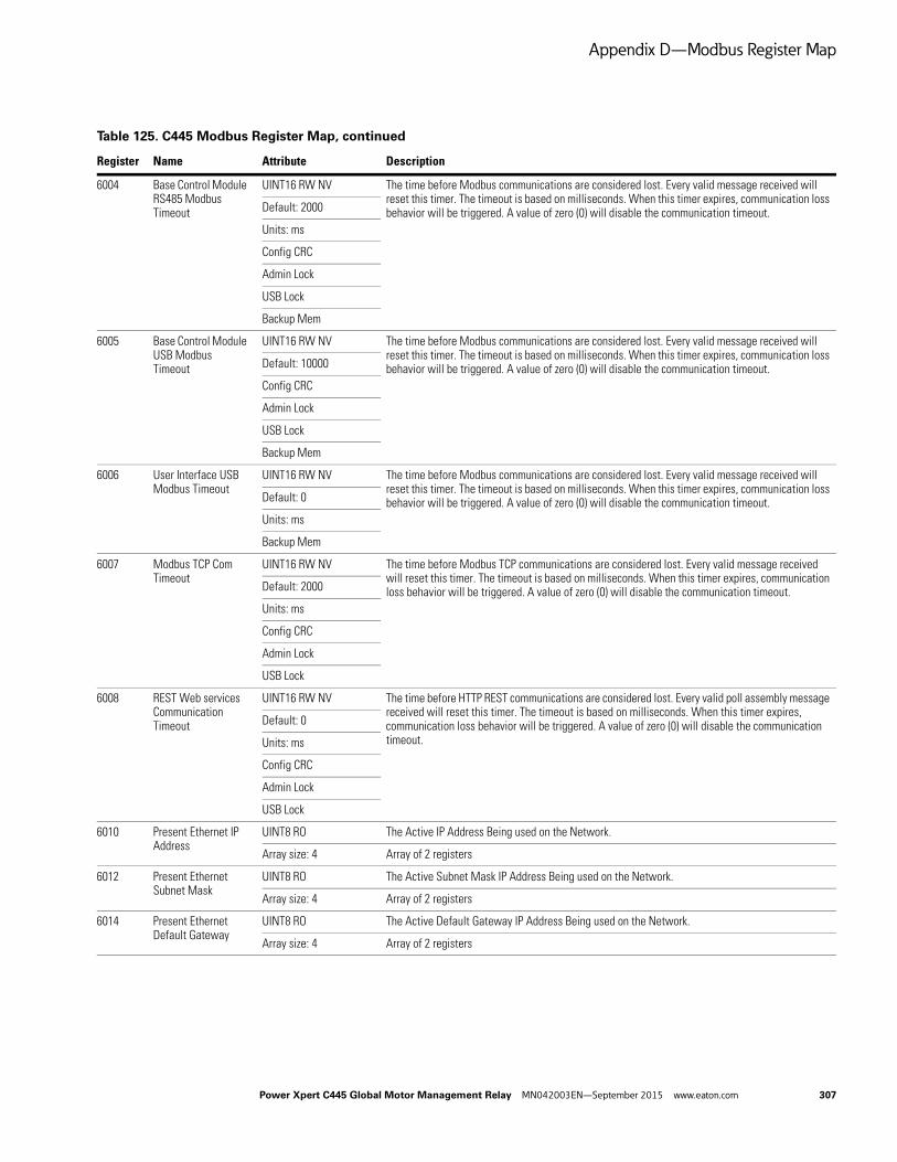
Appendix D—Modbus Register Map
6004 Base Control Module RS485 Modbus Timeout
UINT16 RW NV The time before Modbus communications are considered lost. Every valid message received will reset this timer. The timeout is based on milliseconds. When this timer expires, communication loss behavior will be triggered. A value of zero (0) will disable the communication timeout.Default: 2000
Units: ms
Config CRC
Admin Lock
USB Lock
Backup Mem
6005 Base Control Module USB Modbus Timeout
UINT16 RW NV The time before Modbus communications are considered lost. Every valid message received will reset this timer. The timeout is based on milliseconds. When this timer expires, communication loss behavior will be triggered. A value of zero (0) will disable the communication timeout.Default: 10000
Config CRC
Admin Lock
USB Lock
Backup Mem
6006 User Interface USB Modbus Timeout
UINT16 RW NV The time before Modbus communications are considered lost. Every valid message received will reset this timer. The timeout is based on milliseconds. When this timer expires, communication loss behavior will be triggered. A value of zero (0) will disable the communication timeout.Default: 0
Units: ms
Backup Mem
6007 Modbus TCP Com Timeout
UINT16 RW NV The time before Modbus TCP communications are considered lost. Every valid message received will reset this timer. The timeout is based on milliseconds. When this timer expires, communication loss behavior will be triggered. A value of zero (0) will disable the communication timeout.Default: 2000
Units: ms
Config CRC
Admin Lock
USB Lock
6008 REST Web services Communication Timeout
UINT16 RW NV The time before HTTP REST communications are considered lost. Every valid poll assembly message received will reset this timer. The timeout is based on milliseconds. When this timer expires, communication loss behavior will be triggered. A value of zero (0) will disable the communication timeout.
Default: 0
Units: ms
Config CRC
Admin Lock
USB Lock
6010 Present Ethernet IP Address
UINT8 RO The Active IP Address Being used on the Network.
Array size: 4 Array of 2 registers
6012 Present Ethernet Subnet Mask
UINT8 RO The Active Subnet Mask IP Address Being used on the Network.
Array size: 4 Array of 2 registers
6014 Present Ethernet Default Gateway
UINT8 RO The Active Default Gateway IP Address Being used on the Network.
Array size: 4 Array of 2 registers
Table 125. C445 Modbus Register Map, continued
Register Name Attribute Description
Power Xpert C445 Global Motor Management Relay MN042003EN—September 2015 www.eaton.com 307

Appendix D—Modbus Register Map
6016 Stored Ethernet IP Address
UINT8 RW NV The IP address used in the NV address select configuration. The dip switch settings on the Base Control Module determine if a static IP address of 192.168.1.x, where x= the value on the dip switch settings is used, or if DHCP is used or if the IP address stored at this parameter is used. To use this IP address, enter an IP address for this parameter, power down the C445, set the dip switches for the NVMEM selection and when the unit is powered again, the C445 Ethernet module will be using this IP address.
Array size: 4 Array of 2 registers
Default: 0xFE, 0x01, 0xA8, 0xC0
Config CRC
Admin Lock
USB Lock
6018 Stored Ethernet Subnet Mask
UINT8 RW NV The IP subnet mask used in the NV address select configuration. If the dip switches on the Base Control Module are set for NVMEM, this IP subnet mask will take effect following a power cycle.
Array size: 4 Array of 2 registers
Default: 0x00, 0xFF, 0xFF, 0xFF
Config CRC
Admin Lock
USB Lock
6020 Stored Ethernet Default Gateway
UINT8 RW NV The IP default gateway used in the NV address select configuration.
Array size: 4 Array of 2 registers
Default: 0x01, 0x01, 0xA8, 0xC0
Config CRC
Admin Lock
USB Lock
6022 Ethernet Port 1 Speed Select
UINT16 RW NV Select the Ethernet link speed. Only used when Auto-Negotiate is disabled.
Default: 100 Value Description
Enum 10 10 Mbps
Units: Mbs 100 100 Mbps
Config CRC
Admin Lock
USB Lock
6023 Ethernet Port 1 Speed Actual
UINT16 RO Actual Ethernet link speed. This parameter is used to verify the data rate being used on the Ethernet network. It is read only.
Enum Value Description
Units: Mbs 10 10 Mbps
100 100 Mbps
Table 125. C445 Modbus Register Map, continued
Register Name Attribute Description
308 Power Xpert C445 Global Motor Management Relay MN042003EN—September 2015 www.eaton.com

Appendix D—Modbus Register Map
6024 Ethernet Port 1 Full Duplex Enable
BOOL RW NV Selects the duplex mode. Only used when Auto-Negotiate is disabled. True = Full Duplex False = Half Duplex
Default: 1
Config CRC
Admin Lock
USB Lock
6025 Ethernet Port 1 Full Duplex Enabled
BOOL RO Actual duplex mode. This is a read only parameter, indicating the actual duplex mode on the Ethernet network. True = Full Duplex False = Half Duplex
6026 Ethernet Port 1 Autonegotiate Enable
BOOL RW NV Selects Auto-Negotiation of link speed and duplex. False = Disabled True = Enabled
Default: 1
Config CRC
Admin Lock
USB Lock
6027 Ethernet Port 1 Autonegotiate State
UINT8 RO Active state of the Auto-Negotiation behavior. This parameter indicates the status of auto negotiate on the Ethernet network. This is read only.
Enum Value Description
0 Link inactive
1 Auto negotiation in progress
2 Auto negotiation failed
3 Auto negotiation of duplex failed (speed ok)
4 Auto negotiation success
5 Auto negotiation disabled
6 Port disabled
6028 Ethernet Port 1 Enabled
BOOL RW NV This parameter is used to disable the Ethernet port. True = Enable Port False = Disable Port
Default: 1
Config CRC
Admin Lock
USB Lock
6029 Ethernet Port 2 Speed Select
UINT16 RW NV Select the Ethernet link speed. Only used when Auto-Negotiate is disabled.
Default: 100 Value Description
Enum 10 10 Mbps
Units: Mbs 100 100 Mbps
Config CRC
Admin Lock
USB Lock
6030 Ethernet Port 2 Speed Actual
UINT16 RO Actual Ethernet link speed. This is a read only parameter.
Enum Value Description
Units: Mbs 10 10 Mbps
100 100 Mbps
Table 125. C445 Modbus Register Map, continued
Register Name Attribute Description
Power Xpert C445 Global Motor Management Relay MN042003EN—September 2015 www.eaton.com 309

Appendix D—Modbus Register Map
6031 Ethernet Port 2 Full Duplex Enable
BOOL RW NV Selects the duplex mode. Only used when Auto-Negotiate is disabled. True = Full Duplex False = Half Duplex
Default: 1
Config CRC
Admin Lock
USB Lock
6032 Ethernet Port 2 Full Duplex Enabled
BOOL RO Actual duplex mode. This is a read only parameter. True = Full Duplex False = Half Duplex
6033 Ethernet Port 2 Autonegotiate Enabled
BOOL RW NV Selects Auto-Negotiation of link speed and duplex. False = Disabled True = Enabled (default)
Default: 1
Config CRC
Admin Lock
USB Lock
6034 Ethernet Port 2 Autonegotiate State
UINT8 RO Active state of the Auto-Negotiation behavior. This is read only.
Enum Value Description
0 Link inactive
1 Auto negotiation in progress
2 Auto negotiation failed
3 Auto negotiation of duplex failed (speed ok)
4 Auto negotiation success
5 Auto negotiation disabled
6 Port disabled
6035 Ethernet Port 2 Enabled
BOOL RW NV This parameter Indicates whether an Ethernet port is enabled. True = Port Enabled (default) False = Port Disabled
Default: 1
Config CRC
Admin Lock
USB Lock
6036 Address Conflict Detection Enable
BOOL RW NV Address Conflict Detection enable. ACD provides protection from duplicate IP addresses on the network.
Default: 1
Config CRC
Admin Lock
USB Lock
6037 Address Conflict Detection Status
UINT8 RO Address Conflict Detection State. This is read only.
Enum Value Description
0 No conflict detected
1 Conflict detected—defending
2 Conflict detected—retreated
6038 Address Conflict Detection Conflicted Status
UINT8 RW NV Address Conflict Detection Status. The state of ACD activity when the last conflict was detected.
Default: 0
Range: 0 to 0
Table 125. C445 Modbus Register Map, continued
Register Name Attribute Description
310 Power Xpert C445 Global Motor Management Relay MN042003EN—September 2015 www.eaton.com
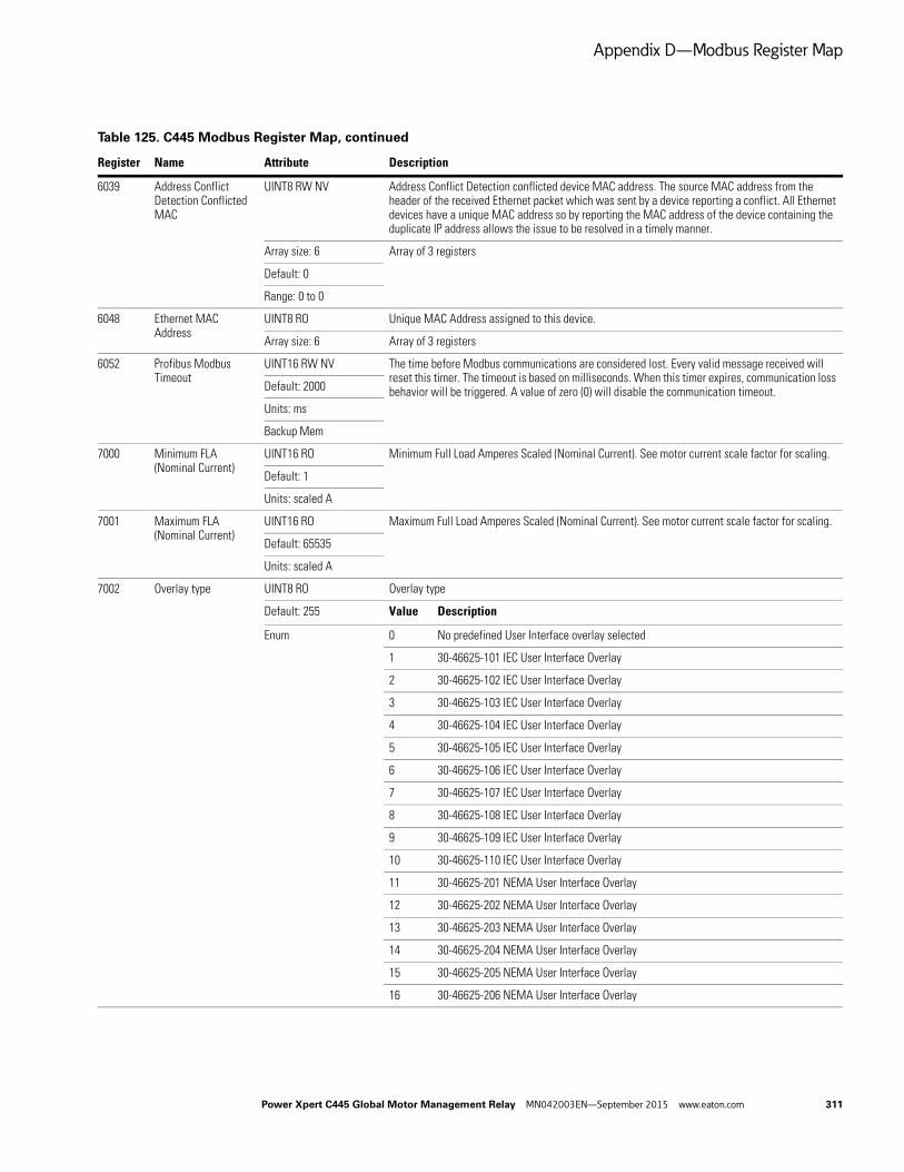
Appendix D—Modbus Register Map
6039 Address Conflict Detection Conflicted MAC
UINT8 RW NV Address Conflict Detection conflicted device MAC address. The source MAC address from the header of the received Ethernet packet which was sent by a device reporting a conflict. All Ethernet devices have a unique MAC address so by reporting the MAC address of the device containing the duplicate IP address allows the issue to be resolved in a timely manner.
Array size: 6 Array of 3 registers
Default: 0
Range: 0 to 0
6048 Ethernet MAC Address
UINT8 RO Unique MAC Address assigned to this device.
Array size: 6 Array of 3 registers
6052 Profibus Modbus Timeout
UINT16 RW NV The time before Modbus communications are considered lost. Every valid message received will reset this timer. The timeout is based on milliseconds. When this timer expires, communication loss behavior will be triggered. A value of zero (0) will disable the communication timeout.Default: 2000
Units: ms
Backup Mem
7000 Minimum FLA (Nominal Current)
UINT16 RO Minimum Full Load Amperes Scaled (Nominal Current). See motor current scale factor for scaling.
Default: 1
Units: scaled A
7001 Maximum FLA (Nominal Current)
UINT16 RO Maximum Full Load Amperes Scaled (Nominal Current). See motor current scale factor for scaling.
Default: 65535
Units: scaled A
7002 Overlay type UINT8 RO Overlay type
Default: 255 Value Description
Enum 0 No predefined User Interface overlay selected
1 30-46625-101 IEC User Interface Overlay
2 30-46625-102 IEC User Interface Overlay
3 30-46625-103 IEC User Interface Overlay
4 30-46625-104 IEC User Interface Overlay
5 30-46625-105 IEC User Interface Overlay
6 30-46625-106 IEC User Interface Overlay
7 30-46625-107 IEC User Interface Overlay
8 30-46625-108 IEC User Interface Overlay
9 30-46625-109 IEC User Interface Overlay
10 30-46625-110 IEC User Interface Overlay
11 30-46625-201 NEMA User Interface Overlay
12 30-46625-202 NEMA User Interface Overlay
13 30-46625-203 NEMA User Interface Overlay
14 30-46625-204 NEMA User Interface Overlay
15 30-46625-205 NEMA User Interface Overlay
16 30-46625-206 NEMA User Interface Overlay
Table 125. C445 Modbus Register Map, continued
Register Name Attribute Description
Power Xpert C445 Global Motor Management Relay MN042003EN—September 2015 www.eaton.com 311

Appendix D—Modbus Register Map
7002 Overlay type UINT8 RO Overlay type, continued
Value Description
17 30-46625-207 NEMA User Interface Overlay
18 30-46625-208 NEMA User Interface Overlay
19 30-46625-209 NEMA User Interface Overlay
20 30-46625-210 NEMA User Interface Overlay
255 Out of box or factory reset state. No User Interface was ever connected
Write-protected by manufacturing lock service. Preserved on WipeNV.
7003 Base Control Module Product Name
STRING8 RO Base Control Module Product Name
Array size: 32 Array of 16 registers
7025 Base Control Module Assigned Name
STRING8 RW NV Base Control Module User Assigned Name
Array size: 32 Array of 16 registers
Default: “Power Xpert C445”
Config CRC
Admin Lock
USB Lock
Backup Mem
7041 Base Control Module Serial Number
UINT32 RO Base Control Module 32bit Device Serial Number.
Write-protected by manufacturing lock service. Preserved on WipeNV.
7043 Base Control Module Product Code
UINT16 RO Base Control Module Product Code numerical
7044 Base Control Module Product Sub Code
UINT16 RO Base Control Module Product Sub Code
Write-protected by manufacturing lock service. Preserved on WipeNV.
7045 Base Control Module Firmware Version
UINT16 RO Base Control Module Firmware Version
Array size: 2 Array of 2 registers
7048 Base Control Module Hardware Version
UINT16 RO Base Control Module Product hardware version numerical
Write-protected by manufacturing lock service. Preserved on WipeNV.
7049 Base Control Module Config CRC
UINT16 RO The configuration CRC is a calculated hash of configuration parameters (see appendix for list of covered parameters).† After a configuration parameter is changed the configuration CRC is recalculated.† While the CRC is being calculated the returned value will be 65535 (0xFFFF).†
7050 Base Control Module Bootloader Version
UINT16 RO Base Control Module Bootloader Version
Array size: 2 Array of 2 registers
7053 Measurement Module Serial Number
UINT32 RO Measurement Module Product Serial Number
7055 Measurement Module Product Code
UINT16 RO Measurement Module Product Code
7056 Measurement Module Product Sub Code
UINT16 RO Measurement Module Product Sub Code
Default: 65535
Table 125. C445 Modbus Register Map, continued
Register Name Attribute Description
312 Power Xpert C445 Global Motor Management Relay MN042003EN—September 2015 www.eaton.com

Appendix D—Modbus Register Map
7057 Measurement Module Firmware Version
UINT16 RO Measurement Module Product Firmware Version
Array size: 2 Array of 2 registers
7060 Measurement Module Hardware Version
UINT16 RO Measurement Module Product Hardware Version
7061 Measurement Module Option Board Type
BYTE RO Measurement Module Option board type.
Bitfield Bit Description Coil
0 Voltage option board present in Measurement Module N/A
1 PTC option board present in Measurement Module N/A
7062 Measurement Module Bootloader Version
UINT16 RO Measurement Module Bootloader Version
Array size: 2 Array of 2 registers
7065 User Interface Serial Number
UINT32 RO User Interface Module 32 bit Device Serial Number.
7067 User Interface Product Code
UINT16 RO User Interface Module Product code numerical
7068 User Interface Product Sub Code
UINT16 RO User Interface Product Sub Code
7069 User Interface Firmware Version
UINT16 RO User Interface Module Firmware version numerical
Array size: 2 Array of 2 registers
7072 User Interface Hardware Version
UINT16 RO User Interface Module Product hardware version numerical
7073 User Interface Bootloader Version
UINT16 RO User Interface Bootloader Version
Array size: 2 Array of 2 registers
7076 Option Card Serial Number
UINT32 RO Option Card 32 bit Device Serial Number.
7078 Option Card Product Code
UINT16 RO Option Card Product Code
Default: 0
7079 Option Card Product Sub Code
UINT16 RO Option Card Product Sub Code
7080 Option Card Product Firmware Version
UINT16 RO Option Card Product Firmware Version
Array size: 2 Array of 2 registers
7083 Option Card Hardware Version
UINT16 RO Option Card Product hardware Version
7084 Option Card Bootloader Version
UINT16 RO Option Card Bootloader Version
Array size: 2 Array of 2 registers
7087 Power Board Serial Number
UINT32 RO Power Board 32 bit Device Serial Number.
7089 Power Board Firmware Version
UINT16 RO The Firmware version of the power board processor.
Array size: 2 Array of 2 registers
7092 Power Board Hardware Version
UINT16 RO Power Board Product hardware version numerical
Table 125. C445 Modbus Register Map, continued
Register Name Attribute Description
Power Xpert C445 Global Motor Management Relay MN042003EN—September 2015 www.eaton.com 313

Appendix D—Modbus Register Map
8004 Input Debounce Time UINT16 RW NV Array of debounce values. A debounce value exists for each input. The debounce applies to both rising and falling edge.
Array size: 4 Array of 4 registers
Default: 20
Range: 5 to 5000
Units: ms
Config CRC
Admin Lock
USB Lock
Backup Mem
8027 Measurement Module Board Ambient Temp
SINT16 RO Measurement Module Ambient temperature measured on the PCB.
Units: ∫C
8028 Measurement Module Max Board Ambient Temp
SINT16 RW NV Measurement Module Maximum ambient temperature measured on the PCB. This value can be set (typically to –40).
Default: –40
Units: ∫C
8145 Low relay control V flag
BOOL RO Flag indicates power supply voltage is too low to pull in relays
8502 Control Word with NetCtrl bit
BYTE RW Network Control Word with NetCtrl bit Bit 0: Run1 Bit 1: Run2 Bit 2: Reserved Bit 3: Fault Reset Bit 4: NetCtrl Bit 5: Test Trip Bit 6: Reserved Bit 7: Reserved
Bitfield Bit Description Coil
0 Run1 command N/A
1 Run2 command N/A
2 Reserved N/A
3 Reset fault N/A
4 Remote control enable (Allow control commands from this control word) N/A
5 Test trip the device N/A
Table 125. C445 Modbus Register Map, continued
Register Name Attribute Description
314 Power Xpert C445 Global Motor Management Relay MN042003EN—September 2015 www.eaton.com

Appendix E—Safety Manual
Appendix E—Safety Manual
“Increased safety” type of protection EEx e according to ATEX directive 94/9/EC.
The C445 global motor management relay provides EEx e protection to motor installed in explosive areas.
EEx e Types of Protection
The overload protection and the thermistor motor protection of C445 global motor management relay comply with requirements for overload protection of explosion-protected motors of the type of protection.
EEx e “increased safety” e.g., according to EN 60079-7.
EC Type Certificate: DEMKO 15 ATEX 1286.
User shall refer C445 safety manual MN042004EN.pdf before installing C445 to protect the motors installed in Hazardous Area.
ATEX Approval for Operation in Areas Subject to Explosion Hazard
The C445 global motor management relay is certified according to ATEX Ex II (2) G and GD for gases and dust.
The C445 global motor management relay is certified for the protection of motors in areas subject to explosion hazard according to:
● ATEX Ex I (M2); equipment group I, category M2 (mining)
● ATEX Ex II (2) GD; equipment group II, category 2 in area GD
Power Xpert C445 Global Motor Management Relay MN042003EN—September 2015 www.eaton.com 315

Appendix E—Safety Manual
Licenses
This product includes embedded software that incorporates or interfaces with the followingthird party software:
lwIP is licensed under the BSD license:Copyright (c) 2001-2004 Swedish Institute of Computer Science.All rights reserved.
Redistribution and use in source and binary forms, with or without modification, are permitted provided that the following conditions are met:
1. Redistributions of source code must retain the above copyright notice, this list of conditions and the following disclaimer.
2. Redistributions in binary form must reproduce the above copyright notice, this list of conditions and the following disclaimer in the documentation and/or other materials provided with the distribution.
3. The name of the author may not be used to endorse or promote products derived from this software without specific prior written permission.
THIS SOFTWARE IS PROVIDED BY THE COPYRIGHT HOLDER “AS IS” AND ANY EXPRESS OR IMPLIED WARRANTIES, INCLUDING, BUT NOT LIMITED TO, THE IMPLIED WARRANTIES OF MERCHANTABILITY AND FITNESS FOR A PARTICULAR PURPOSE ARE DISCLAIMED. IN NO EVENT SHALL THE AUTHOR BE LIABLE FOR ANY DIRECT, INDIRECT, INCIDENTAL, SPECIAL, EXEMPLARY, OR CONSEQUENTIAL DAMAGES (INCLUDING, BUT NOT LIMITED TO, PROCUREMENT OF SUBSTITUTE GOODS OR SERVICES; LOSS OF USE, DATA, OR PROFITS; OR BUSINESS INTERRUPTION) HOWEVER CAUSED AND ON ANY THEORY OF LIABILITY, WHETHER IN CONTRACT, STRICT LIABILITY, OR TORT (INCLUDING NEGLIGENCE OR OTHERWISE) ARISING IN ANY WAY OUT OF THE USE OF THIS SOFTWARE, EVEN IF ADVISED OF THE POSSIBILITY OF SUCH DAMAGE.
www.FreeRTOS.org
316 Power Xpert C445 Global Motor Management Relay MN042003EN—September 2015 www.eaton.com


At Eaton, we’re energized by the challenge of powering a world that demands more. With over 100 years experience in electrical power management, we have the expertise to see beyond today. From ground-breaking products to turnkey design and engineering services, critical industries around the globe count on Eaton.
We power businesses with reliable, efficient and safe electrical power management solutions. Combined with our personal service, support and bold thinking, we are answering tomorrow’s needs today. Follow the charge with Eaton. Visit eaton.com/electrical.
Eaton is a registered trademark.
All other trademarks are property of their respective owners.
Eaton
1000 Eaton BoulevardCleveland, OH 44122 United StatesEaton.com
© 2015 EatonAll Rights ReservedPrinted in USAPublication No. MN042003EN / Z17179September 2015