power transmission systems
TRANSCRIPT

Power Transmission Projects
MANUALOF
SPECIFICATIONS and STANDARDS
Rajasthan Rajya Vidyut Prasaran Nigam Limited
2
INDEX
Abbreviations ......................................................................................................................................................... 3Definitions................................................................................................................................................................ 6SECTION 1-GENERAL ..........................................................................................................................................8PART A TRANSMISSION LINESECTION 2- TRANSMISSION TOWER......................................................................................................... 16SECTION 3- INSULATORS ............................................................................................................................... 24SECTION 4- CONDUCTOR ............................................................................................................................... 28SECTION 5- GROUND WIRE ........................................................................................................................... 31SECTION 6- OPTICAL GROUND WIRE........................................................................................................ 33SECTION 7- ERECTION, TESTING AND COMMISSIONING ................................................................. 35PART B SUB STATIONSSECTION 8- AIR INSULATED SUBSTATION (AIS) ................................................................................. 39SECTION 9- GAS INSULATED SUBSTATION (GIS)................................................................................. 57SECTION 10- CIVIL WORKS ........................................................................................................................... 65

3
AbbreviationsThe following abbreviations are used in this Manual of Specifications and Standards:Abbreviation Full NameAC Alternating CurrentACSR Aluminium Conductor Steel ReinforcedADSS All Dielectric Self-SupportingAIS Association of Information SystemASTM American Society for Testing and MaterialsBIS Bureau of Indian StandardsBS British StandardsCA The Concession Agreement entered into between theConcessionaire and the AuthorityCBI& P Central Board of Irrigation and PowerCCEA Cabinet Committee of Economic AffairsCEA Central Electricity AuthorityCEB/FIB Model Code for Concrete Structures “CEB Bulletin”CENELEC European Committee for Electro technical StandardizationCTU Central Transmission UtilityDC Double CircuitDWSM Dual-Window Single ModeE&M Electrical and MechanicalEIA Energy Information AdministrationEHT Extra High TensionEN Euro Norm (European) StandardEPC Engineering Procurement and ConstructionGOI Government of IndiaGOR Government of RajasthanGPS Global Positioning SystemGSS Galvanized Steel StrandedHz Hertz
4
HV High Voltage (as per Indian Electricity Rules)ICAO International Civil Aviation OrganizationIE Independent EngineerIEC International Electro technical CommissionIEEE Institution of Electrical and Electronic EngineersIEGC Indian Electricity Grid CodeIS Indian StandardISA Independent Safety AssessorISO International Standards OrganizationITU-T International Telecommunication Union-TelecommunicationStandardization SectorJIS Japanese Industrial StandardsKN Kilo NewtonKV Kilo VoltKW Kilo wattLAN Local Area NetworkLED Light Emitting DiodeLV Low Voltage (as per Indian Electricity Rules)MCB Miniature Circuit BoardMDB Main Distribution BoardNBC National Building Code (of India)NFPA National Fire Protection AssociationNMS Network Management SystemNEMA National Electric Manufacture AssociateO&M Operation and MaintenanceOPGW Optical. Ground WirePPP Public Private PartnershipPTFE Poly Tetra Fluoro EthylenePVC Polyvinyl chlorideP&T Power and TelecomRCC Reinforced Cement ConcreteRI Ride Index

5
RMS Root mean squareROW Right of WayRVPN Rajasthan Vidyut Prasaran NigamSCADA Supervisory Control and Data AcquisitionSTU State Transmission UtilityUV Ultra VioletUPS Uninterrupted Power SupplyVGF Viability Gap FundingVVVF Variable Voltage Variable FrequencyWAN Wide Area NetworkXLPE Cross Linked Poly Ethylene
6
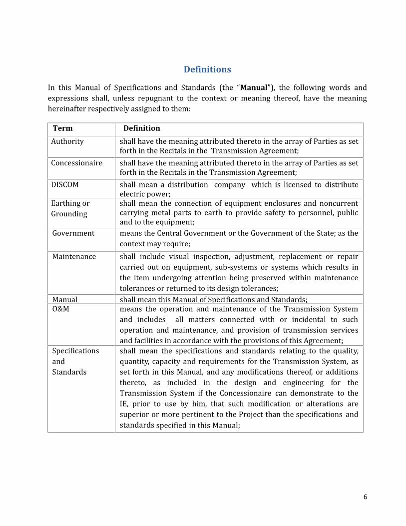
DefinitionsIn this Manual of Specifications and Standards (the “Manual”), the following words andexpressions shall, unless repugnant to the context or meaning thereof, have the meaninghereinafter respectively assigned to them:Term DefinitionAuthority shall have the meaning attributed thereto in the array of Parties as setforth in the Recitals in the Transmission Agreement;Concessionaire shall have the meaning attributed thereto in the array of Parties as setforth in the Recitals in the Transmission Agreement;DISCOM shall mean a distribution company which is licensed to distributeelectric power;Earthing orGrounding shall mean the connection of equipment enclosures and noncurrentcarrying metal parts to earth to provide safety to personnel, publicand to the equipment;Government means the Central Government or the Government of the State; as thecontext may require;Maintenance shall include visual inspection, adjustment, replacement or repaircarried out on equipment, sub-systems or systems which results inthe item undergoing attention being preserved within maintenancetolerances or returned to its design tolerances;Manual shall mean this Manual of Specifications and Standards;O&M means the operation and maintenance of the Transmission Systemand includes all matters connected with or incidental to suchoperation and maintenance, and provision of transmission servicesand facilities in accordance with the provisions of this Agreement;SpecificationsandStandards shall mean the specifications and standards relating to the quality,quantity, capacity and requirements for the Transmission System, asset forth in this Manual, and any modifications thereof, or additionsthereto, as included in the design and engineering for theTransmission System if the Concessionaire can demonstrate to theIE, prior to use by him, that such modification or alterations aresuperior or more pertinent to the Project than the specifications andstandards specified in this Manual;

7
Term DefinitionSubstation means a station for transforming or converting electricity for thetransmission thereof and includes transformers, converters,switchgears, capacitors, synchronous condensers, structures, cableand other appurtenant equipment and any buildings used for thatpurpose and the site thereof;Tests shall mean all the tests necessary to determine the completion ofTransmission System in accordance with the provisions of theConcession Agreement;Works shall refer to all labor, materials and equipment to be fitted into thestations and structures that are necessary to implement the Operationand Maintenance requirements;Others Any capitalized term used herein and not specifically defined shallhave the meaning ascribed to such term in the Model TransmissionAgreement notified by the Ministry of Power under Section 63 of theElectricity Act, 2003 and published by the Planning Commission
8
SECTION 1
GENERAL
1.1 This Manual is applicable for Planning, Design, Construction, Operation andMaintenance of a) 400kV D/C (Twin ACSR Moose) Transmission Lines b) associated400kV/220kV substation, through Public Private Partnerships ("the Project"). Thescope of the work shall be as defined in the Concession Agreement. This Manualshall be read harmoniously with the intent of the Concession Agreement.1.2 The System Capacity shall be constructed, completed, operated and maintained inconformity with the Specifications and Standards set forth herein.1.3 Concessionaire shall propose Air insulated or Gas insulated substations as proposedin the General Layouts attached with the manual.1.4 The requirements of Transmission lines and substation are covered in Part A, andPart B respectively, of this manual.1.5 The Transmission System shall conform to the requirements of design andspecifications set out in this Manual, which unless specified otherwise, are theminimum prescribed. The project report and other information provided by theAuthority shall be used by the Concessionaire only for its own reference and forcarrying out further investigations. The Concessionaire shall be solely responsiblefor undertaking all the surveys, investigations and detailed designs in accordancewith Good Industry Practice and shall have no claim against the Authority for anyloss, damage, risks, costs, liabilities or obligations arising out of or in relation to suchsurveys, investigations and designs.1.6 All works, methods and workmanship shall be in accordance with this Manual ofSpecifications and Standards and Good Industry Practice.1.7 All plant and equipment, including replacements thereof, shall be new, unused, andof the most recent or latest models unless provided otherwise in the TransmissionAgreement.1.8 Concessionaire shall carry out residual life assessment and appropriate conditionbased maintenance in accordance with recommendations of “CBI&P Manuals onTransmission Line Maintenance” and “CBI&P Manual on EHV Substations” and also

9
carry out general maintenance as per the Maintenance Manual and Good IndustryPractice so as to non-intrusively determine equipment health, arrest unduedeterioration in performance, improve availability, regain lost capacity and extenduseful life beyond normal standard life span.1.9 The Concessionaire shall take all requisite measures for appropriate operation andmaintenance as per relevant codes, standards and the Maintenance Manual andadopt requisite life extending procedures or replacement measures to guard againstundue capacity loss and de-rating of equipment as per Good Industry Practice.1.10 At least 2 weeks prior to commencement of the work, the Concessionaire shall drawup a Quality Assurance Manual (QAM) covering the Quality System (QS), QualityAssurance Plan (QAP) and documentation for all aspects of the Project works andsend three copies each to the Independent Engineer (IE) for review. The QAM shallconform to Applicable Laws, Good Industry Practice in vogue and the provisions ofthe Concession Agreement.1.11 The Transmission System shall conform to the following Acts, Rules, Regulationsand Codes for the Transmission System:(a) Indian Electricity Act - 2003;(b) Indian Electricity Grid Code (IEGC);(c) Central Electricity Authority (Technical Standards for Connectivity to theGrid) Regulations, 2013;(d) CEA (Technical Standards for construction, operation and maintenance ofElectrical Plants and Electric Lines) Regulation, 2010;(e) CEA (Safety requirements for construction, operation and maintenance oftransmission lines) Regulation, 2011;(f) CEA (Grid Standards for operation and maintenance of transmission lines)Regulation, 2006;(g) CEA (Safety and electricity supply) Regulation, 2008 and other applicableLaws;(h) Central Board of Irrigation and Power (CBI&P): Manual on CommissioningProcedures for Transmission Line;(i) Central Board of Irrigation and Power (CBI&P): Manual on Maintenance ofTransmission Line;(j) Central Board of Irrigation and Power (CBI&P): Transmission Line Manual;(k) Central Board of Irrigation and Power (CBI&P): EHV substation Manual; and(l) Central Electricity Authority (Installation and Operation of Meters)Regulations, 2010.

10
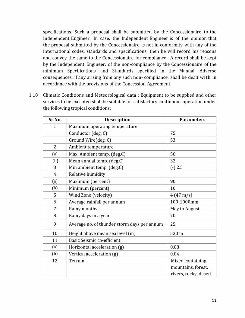
In the event of conflict between standards and specifications prescribed in two ormore of the aforesaid codes, the Concessionaire shall be at liberty to rely on one ofthe aforesaid codes and on Good Industry Practice. Provided, however, that in theevent of any such conflict, the following codes shall have overriding priority in theorder listed below:(i) Specifications and Standards set out in this Manual; and(ii) CEA (Technical Standards for construction, operation and maintenance ofElectrical Plants and Electric Lines) Regulations, 2010.In the event of anyconflict between the requirement of the International Standards or codes andthe requirement of the BIS Standards or Codes, the latter shall prevail.1.12 The latest version of the aforesaid codes, standards and specifications, which havebeen published before the last date of bid submission shall be considered applicable.1.13 The terms ‘Inspector’ and ‘Engineer’ used in the aforesaid codes, standards orspecifications shall be deemed to be substituted by the term “IndependentEngineer”, to the extent it is consistent with the provisions of the ConcessionAgreement and this Manual. The role of the Independent Engineer (IE) shall be asdefined in the Concession Agreement.1.14 Where no standards exist, as in the case of patented or special materials, all suchequipments and materials shall be of reputed make. Full details of the material andany quality control tests to which they may be subjected shall be submitted to theIndependent Engineer for review and comments, if any.1.15 In the absence of any specific provision on any particular issue in the aforesaidcodes, standards or specifications read in conjunction with the Specificationsand Standards contained in this Manual, the Concessionaire shall be at liberty torely on any international standard in consultation with the IE.1.16 The design of a transmission system shall be fully integrated and compatible with allother transmission systems that constitute the transmission network of the State sothat the overall requirements of the Transmission System may met.1.17 The requirements stated in the Manual are the minimum. The Concessionairewill, however, be free to adopt international practices, alternative specifications,materials and standards to bring in innovation in the design and construction;provided they are better or comparable with the standards prescribed in theManual. The specifications and techniques which are not included in the aforesaidcodes, standards or specifications shall be supported with authentic standards andspecifications reflected in other internationally recognized codes, standards and
11
specifications. Such a proposal shall be submitted by the Concessionaire to theIndependent Engineer. In case, the Independent Engineer is of the opinion thatthe proposal submitted by the Concessionaire is not in conformity with any of theinternational codes, standards and specifications, then he will record his reasonsand convey the same to the Concessionaire for compliance. A record shall be keptby the Independent Engineer, of the non-compliance by the Concessionaire of theminimum Specifications and Standards specified in the Manual. Adverseconsequences, if any arising from any such non- compliance, shall be dealt with inaccordance with the provisions of the Concession Agreement.1.18 Climatic Conditions and Meteorological data : Equipment to be supplied and otherservices to be executed shall be suitable for satisfactory continuous operation underthe following tropical conditions:Sr.No. Description Parameters1 Maximum operating temperatureConductor (deg. C) 75Ground Wire(deg. C) 532 Ambient temperature(a) Max. Ambient temp. (deg.C) 50(b) Mean annual temp. (deg.C) 323 Min ambient temp. (deg.C) (-) 2.54 Relative humidity(a) Maximum (percent) 90(b) Minimum (percent) 105 Wind Zone (velocity) 4 (47 m/s)6 Average rainfall per annum 100-1000mm7 Rainy months May to August8 Rainy days in a year 709 Average no. of thunder storm days per annum 2510 Height above mean sea level (m) 530 m11 Basic Seismic co-efficient(a) Horizontal acceleration (g) 0.08(b) Vertical acceleration (g) 0.0412 Terrain Mixed containingmountains, forest,rivers, rocky, desertetc

12
1.19 General considerations for planning, design and construction:1.19.1 The Concessionaire shall perform the detailed survey along the route alignment,prepare route profiles, tower spotting, optimization of tower locations,measurement of soil resistivity and geotechnical investigation at specified locations,assessment of quantities of different types of towers, body extensions, towerschedule, tower capacity chart, sag template, sag tension chart, etc.1.19.2 The Concessionaire shall also be responsible for undertaking check survey requiredfor starting the work of foundations. The detailed survey and check survey shall beperformed by qualified and experienced personnel and supervised by the qualifiedsurveyor.1.19.3 Right-of-way : Clearing of obstructions falling in the right-of-way as per IS 5613(Part 3, Section 2) and lopping or trimming of the portion of the trees obstructingthe line of sight during detailed survey and falling within the minimum electricalclearance zone shall be the responsibility of the Concessionaire.1.19.4 The Concessionaire shall perform detailed soil investigation at all angle towerlocations and tower locations for railway crossings, major road crossings, powerline crossings and wherever soil strata differ from normal locations. Detailedgeotechnical investigation are required to be performed at specified number oftower locations to provide sufficiently accurate information, both general andspecific, about the substrata profile and relevant soil and rock parameters to verifythe bearing capacity, and uplift resistance and settlement constraints at site on thebasis of which the foundation of transmission line towers can be classified anddesigned rationally.1.19.5 All crossings of power lines - road crossings, railway crossings, river crossings,power line to power line and power line to tele-communication lines etc. - shall beundertaken in compliance with the requirements of the Indian Electricity Rules,1956, applicable codes, the requirements of concerned authorities owning the en-route utility in respect of safety of its users, and security of the TransmissionSystem, in accordance with Good Industry Practice. All Statutory Clearances likePTCC, Forest, railway crossing, wild life, aviation etc to be arranged byconcessionaire.1.19.6 The Concessionaire shall perform detailed topography survey to define the contoursof the substation/s sites. The report shall be detailed and shall form basis of thefinalization of the substation level. Approach road for the substation site andconnection points for the utilities such as plumbing and drainage system in the

13
vicinity shall be clearly brought out.1.19.7 The Concessionaire shall perform detailed soil investigation at the substation site.Detailed geotechnical investigation are required to be performed at specifiednumber locations to provide sufficiently accurate information, both general andspecific, about the substrata profile and relevant soil and rock parameters to verifythe bearing capacity, and uplift resistance and settlement constraints at site on thebasis of which the foundation of equipment, transformers, control building in case ofAIS substation/ GIS building can be classified and designed rationally.1.19.8 The Concessionaire shall measure soil resistivity at the substation locations as perlatest codes and standards.1.19.9 The Concessionaire shall comply with all the applicable statutory rules pertaining toFactory Act, Fire Safety Rule, Water Act for Pollution control, Explosives Act, etc.Provisions of Safety, Health and Welfare according to Factories Act shall also becomplied with. Statutory clearances and norms of State Pollution Control Boardshall be followed.1.20 Safety measures:1.20.1 The Concessionaire shall develop, implement and administer a surveillance andsafety program for providing a safe environment on or about the Project, and shallcomply with the safety requirements set forth in the Concession Agreement.1.20.2 The Concessionaire shall also be responsible for ensuring compliance of all labourlaws and regulations including those relating the welfare of workers engaged bothdirectly and indirectly on the Project, besides their occupational safety and health.1.20.3 The Concessionaire shall set up a field laboratory for testing of materials andfinished products as stipulated in QAM. It shall make necessary arrangements foradditional/ conformity testing of any materials/products at the governmentaccredited laboratory, for which facilities at site laboratory are not available.1.21 Environment mitigation measures: The Concessionaire shall carry out tests andmonitor various parameters impacting the environment of the Project keeping inview the guidelines of the Ministry of Environment and Forests and submitproposals for mitigation of adverse environment impact for review and commentsof the IE, and undertake implementation thereof.1.22 Project Monitoring System: The Concessionaire shall procure informationtechnology based system for effective project monitoring. The IT system shall
14
monitor status of engineering, design, testing, supplies and physical progress of siteactivities as well as O&M and help in identifying the bottlenecks in achieving thescheduled completion of works.1.23 Review and comments by the Independent Engineer: In cases where theConcessionaire is required to send any drawings or documents to theIndependent Engineer for review and comments, and in the event such commentsare received by the Concessionaire, it shall duly consider such commentsin accordance with the Concession Agreement and Good Industry Practice fortaking appropriate action thereon.1.24 Tests : Factory Inspection Tests (FAT) shall be performed on all the equipment atthe manufacturer’s works before dispatch as per relevant Indian/Internationalstandards and as per Good Industry Practice.All the systems shall be tested as per relevant Indian/International standards and asper Good Industry Practice.The Concessionaire shall make necessary arrangements for conformity testing ofany materials/products at the government accredited laboratory/ field laboratoryas stipulated in QAM.1.25 Definitions and Interpretation:1.25.1 All the obligations of the Concessionaire arising out of the provisions of this Manualshall be discharged in a manner that conforms to the provisions of the TransmissionAgreement.1.25.2 Unless specified otherwise in this Manual, the definitions contained in the ModelTransmission Agreement (MTA) for Public Private Partnership (PPP) in PowerTransmission System as published by the Planning Commission, Government ofIndia shall apply.

15
Part- ATRANSMISSION LINE

16
SECTION 2
TRANSMISSION TOWER
2.1 Design, Manufacturing, Fabrication, Galvanizing and Testing of towers shall conformto the provisions of IS: 5613 and IS: 802 (Part-1/2 and 3) as amended upto date.2.2 The codes of Bureau of Indian Standards (BIS) mentioned below or equivalentInternational Standards as amended up to date shall be applicable to the materialand process used in the manufacture of towers and tower accessories:IndianStandards (IS) Title InternationalandInternationallyrecognizedStandardIS 2 Rules for rounding off numerical valuesIS 209 Zinc Ingot- SpecificationIS-269 Ordinary Portland Cement, 33 grade-SpecificationIS 278 Galvanized steel barbed wire for fencing-SpecificationIS 432 (Part 1) Mild steel and medium tensile steel bars and harddrawn steel wire for concrete reinforcement, Part1: Mild steel and medium tensile steel barsIS 432 (Part 2) Mild steel and medium tensile steel bars and harddrawn steel wire for concrete reinforcement, Part2: Hard-drawn steel wireIS 456 Plain and reinforced concrete- Code of practiceIS 800 General Construction In Steel - Code of PracticeIS 802(Part 1/Sec1)andIS 802(Part 1/Sec 2)
Code of practice for use of structural steel inoverhead transmission line towers: Materials andloads permissible stresses“ Note: IS-802 1995(part1/sec1, Clause No. 12.1.2specifies “nil wind condition” for SuspensionTowers under broken wire condition, which maybe substituted by “75% wind condition” for thepurpose of design and construction”

17
IS 802 (Part 2) Code of practice for use of structural steel inoverhead transmission line: Fabrication,galvanizing, inspection and packingIS 802 (Part 3) Code of practice for use of structural steel inoverhead transmission line: Testing.IS 808 Dimensions for hot rolled steel beams, columnchannels and Angle sectionsIS 875 Code of Practice for Design Loads (Other thanEarthquakes) for Buildings and Structures.IS 1200 Method of Measurement of Building and CivilEngineering Works.IS 1363 (Part 1) Hexagon Head Bolts, Screws and Nuts of ProductGrade C - Part 1 : Hexagon Head Bolts (Size RangeM 5 to M 64)IS 1363 (Part 3) Hexagon Head Bolts, Screws and Nuts of ProductGrade C - Part 3 : Hexagon Nuts (Size Range M5 toM64)IS 1367 (Part 1) Technical supply conditions for threaded steelfasteners, Part 1: General requirements for bolts,screws and studsIS 1367 (Part 3) Technical supply conditions for threaded steelfasteners, Part 3: Mechanical properties offasteners made of carbon steel and alloy steelIS 1367 (Part 6) Technical supply conditions for threaded steelfasteners, Part 6: Mechanical properties and Testmethods for nuts with specified proof loadsIS 1367 (Part13) Technical supply conditions for threaded steelfasteners, Part 13: Hot Dip Galvanized Coatings onthreaded FastenersIS 1477 Code of Practice for Painting of Ferrous Metals inBuildings.IS 1489 Portland Pozzolana cementIS 1573 Specification for Electroplated coatings for zincon iron and steel.IS 1786 High Strength Deformed Steel Bars and Wires forConcrete ReinforcementIS 1852 Rolling and Cutting Tolerances of Hot Rolled SteelProducts.
18
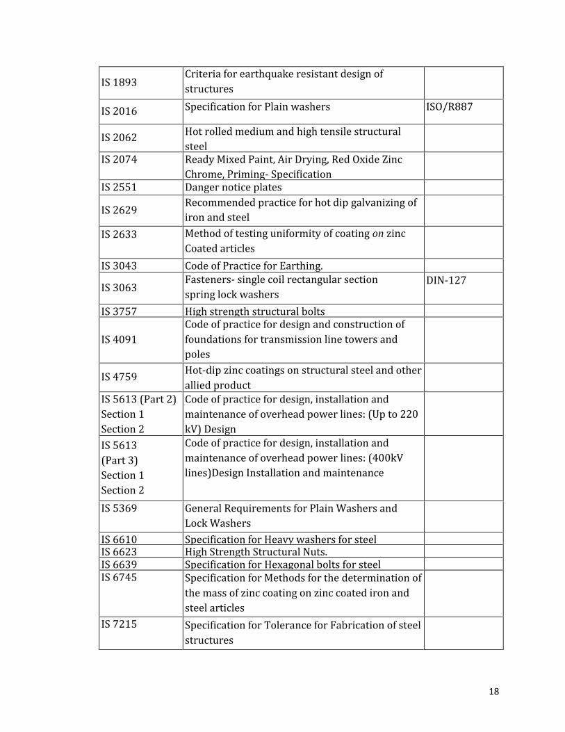
IS 1893 Criteria for earthquake resistant design ofstructuresIS 2016 Specification for Plain washers ISO/R887IS 2062 Hot rolled medium and high tensile structuralsteelIS 2074 Ready Mixed Paint, Air Drying, Red Oxide ZincChrome, Priming- SpecificationIS 2551 Danger notice platesIS 2629 Recommended practice for hot dip galvanizing ofiron and steelIS 2633 Method of testing uniformity of coating on zincCoated articlesIS 3043 Code of Practice for Earthing.IS 3063 Fasteners- single coil rectangular sectionspring lock washers DIN-127IS 3757 High strength structural boltsIS 4091 Code of practice for design and construction offoundations for transmission line towers andpolesIS 4759 Hot-dip zinc coatings on structural steel and otherallied productIS 5613 (Part 2)Section 1Section 2 Code of practice for design, installation andmaintenance of overhead power lines: (Up to 220kV) DesignInstallation and maintenanceIS 5613(Part 3)Section 1Section 2
Code of practice for design, installation andmaintenance of overhead power lines: (400kVlines)Design Installation and maintenanceIS 5369 General Requirements for Plain Washers andLock WashersIS 6610 Specification for Heavy washers for steelstructuresIS 6623 High Strength Structural Nuts.IS 6639 Specification for Hexagonal bolts for steelstructuresIS 6745 Specification for Methods for the determination ofthe mass of zinc coating on zinc coated iron andsteel articlesIS 7215 Specification for Tolerance for Fabrication of steelstructures
19
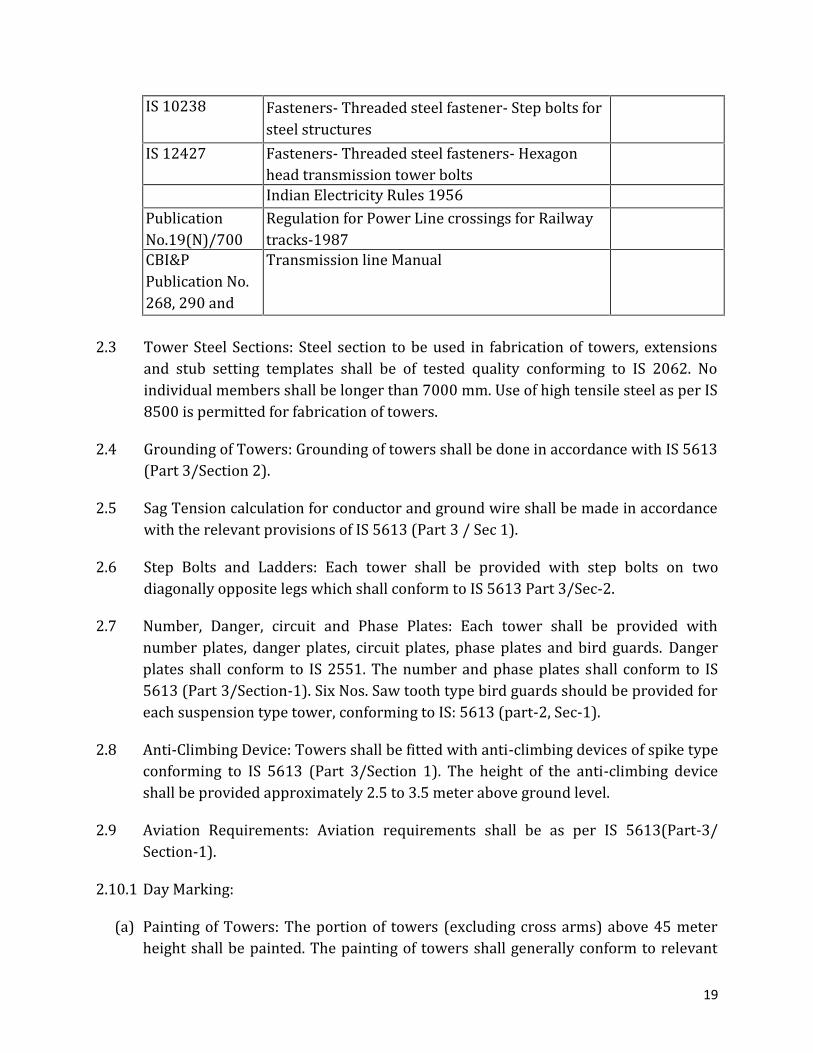
IS 10238 Fasteners- Threaded steel fastener- Step bolts forsteel structuresIS 12427 Fasteners- Threaded steel fasteners- Hexagonhead transmission tower boltsIndian Electricity Rules 1956PublicationNo.19(N)/700 Regulation for Power Line crossings for Railwaytracks-1987CBI&PPublication No.268, 290 and293Transmission line Manual
2.3 Tower Steel Sections: Steel section to be used in fabrication of towers, extensionsand stub setting templates shall be of tested quality conforming to IS 2062. Noindividual members shall be longer than 7000 mm. Use of high tensile steel as per IS8500 is permitted for fabrication of towers.2.4 Grounding of Towers: Grounding of towers shall be done in accordance with IS 5613(Part 3/Section 2).2.5 Sag Tension calculation for conductor and ground wire shall be made in accordancewith the relevant provisions of IS 5613 (Part 3 / Sec 1).2.6 Step Bolts and Ladders: Each tower shall be provided with step bolts on twodiagonally opposite legs which shall conform to IS 5613 Part 3/Sec-2.2.7 Number, Danger, circuit and Phase Plates: Each tower shall be provided withnumber plates, danger plates, circuit plates, phase plates and bird guards. Dangerplates shall conform to IS 2551. The number and phase plates shall conform to IS5613 (Part 3/Section-1). Six Nos. Saw tooth type bird guards should be provided foreach suspension type tower, conforming to IS: 5613 (part-2, Sec-1).2.8 Anti-Climbing Device: Towers shall be fitted with anti-climbing devices of spike typeconforming to IS 5613 (Part 3/Section 1). The height of the anti-climbing deviceshall be provided approximately 2.5 to 3.5 meter above ground level.2.9 Aviation Requirements: Aviation requirements shall be as per IS 5613(Part-3/Section-1).2.10.1 Day Marking:(a) Painting of Towers: The portion of towers (excluding cross arms) above 45 meterheight shall be painted. The painting of towers shall generally conform to relevant
20
provisions in IS 1477 (Part 1 and2). The paints to be used for painting shall be inaccordance with IS 2074.For Surface preparation, the etching of galvanized surface of erected towermembers with suitable etching or wash primer is to be done as per IS:1477. Onecoat of wash primer and zinc chromate primer shall be applied. The primer to beused shall conform to IS: 2074.For final painting, two coats of international deep orange or red and snow whitepaint at alternate intervals are to be applied.(b) Line/Span Markers: Sphere type span marker of 600mm/ diameter shall beprovided on the earth wire. The design of the markers and their fixing arrangementshould be such that they can withstand the wind pressure and shall not induceexcessive amount of vibration strain on earth wire. Appropriate clamping device ofcast aluminium alloy are to be provided for clamping. The spheres are hollow andUV protected against fading of color and weathering as per IS.2.10.2 Visual Aids: Visual aids (Night Markers) consisting of medium intensity and two/four (as applicable) low intensity lights along with storage battery and solar panel,control panel, cables, clamps, other accessories etc. shall be provided on thetransmission line towers as per the provision of IS –5613 (Part -II/ section –I) latestamendments regarding night and day visual aids for denoting transmission linestructure as per the requirement of Directorate of Flight safety. Low and Mediumintensity lights to be provided on each tower shall conform to the ICAO requirement/relevant BS and shall have weather protection of minimum IP-55 class. Storagebattery, solar panels, control panels, cables and clamps shall conform to relevantIndian Standard or any other internationally recognized standard. These should behighly resistant to water, abrasion, nail, impact and other environmental factors.Necessary sensor/timer shall be provided in the system to “switch on” the lightautomatically in the evening and poor visibility period and switch off the sameduring day time and normal visibility period.2.11 Galvanization: Hot dip Galvanization of tower members shall conform to IS: 2629and IS: 4759 and that of fasteners to IS: 1367 (Part-13) and IS: 5358. Spring washersshall be electro-galvanized as per grade4 of IS: 1573. All galvanized material shallwithstand tests as per IS: 2633.2.12 Fasteners-Bolts, Nuts and Washers: Half threaded hexagonal, chamfered, galvanisedGI bolts and nuts conforming to IS: 6639 and IS: 12427 of property class 5.6 as
21
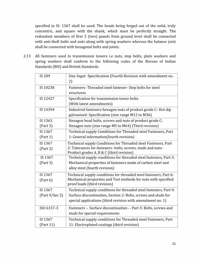
specified in IS: 1367 shall be used. The heads being forged out of the solid, trulyconcentric, and square with the shank, which must be perfectly straight. Theredundant members of first 2 (two) panels from ground level shall be connectedwith anti-theft bolts and nuts along with spring washers whereas the balance jointshall be connected with hexagonal bolts and joints.2.13 All fasteners used in transmission towers i.e nuts, step bolts, plain washers andspring washers shall conform to the following codes of the Bureau of IndianStandards (BIS) and British Standards.IS 209 Zinc Ingot- Specification (Fourth Revision with amendment no.2)IS 10238 Fasteners- Threaded steel fastener- Step bolts for steelstructuresIS 12427 Specification for transmission tower bolts(With latest amendments)IS 14394 Industrial fasteners-hexagon nuts of product grade C- Hot dipgalvanized- Specification (size range M12 to M36)IS 1363(Part 3) Hexagon head bolts, screws and nuts of product grade C:Hexagon nuts (size range M5 to M64) (Third revision)IS 1367(Part 1) Technical supply Conditions for Threaded steel Fasteners, Part1: General information(fourth revision)IS 1367(Part 2) Technical supply Conditions for Threaded steel Fasteners, Part2: Tolerances for fasteners- bolts, screws, studs and nuts-Product grades A, B & C (third revision)IS 1367(Part 3) Technical supply conditions for threaded steel fasteners, Part 3:Mechanical properties of fasteners made of carbon steel andalloy steel (fourth revision)IS 1367(Part 6) Technical supply conditions for threaded steel fasteners, Part 6:Mechanical properties and Test methods for nuts with specifiedproof loads (third revision)IS 1367(Part 9/Sec 2) Technical supply conditions for threaded steel fasteners, Part 9:Surface discontinuities, Section 2: Bolts, screws and studs forspecial applications (third revision with amendment no. 1)ISO 6157-3 Fasteners -- Surface discontinuities -- Part 3: Bolts, screws andstuds for special requirementsIS 1367(Part 11) Technical supply conditions for Threaded steel Fasteners, Part11: Electroplated coatings (third revision)

22
IS 1367(Part 13) Technical supply conditions for threaded steel fasteners, Part13: Hot Dip Galvanized Coatings on threaded Fasteners (secondrevision)IS 1367(Part 17) Industrial fasteners - Threaded steel fasteners - Technicalsupply conditions Part 17 Inspection, sampling and acceptanceprocedure (fourth revision)IS 1367(Part 18) Industrial Fasteners - Threaded Steel Fasteners - TechnicalSupply Conditions - Part 18 : Packaging (third revision)IS 1368 Dimensions for end of parts with external ISO metric threads(third revision)IS 1369 (Part1) Fasteners - Thread Run-Outs and Undercuts Part 1 Dimensionsfor Screw Thread Run-Outs for External ISO Metric Threads(third revision)IS 1369 (Part2) Fasteners - Thread runout and undercuts Part 2 Dimensions forscrew thread undercuts for external ISO metric threads (thirdrevision)IS 1369 (Part3) Fasteners - Thread Run-Outs and Undercuts - Part 3 :Dimensions for Screw Thread Run-Outs and Undercuts forInternal Threads (Blind Tapped Holes) (third revision)IS 2016 Specification for plain washers (First revision with amendmentno. 4)IS 2633 Methods for testing uniformity of coating on zinc coated articles(Second revision)IS 4218(Part 1) ISO general purpose metric screw threads, Part 1: Basic anddesign profile (Second revision)ISO 68-1:1998(Part 2) ISO general purpose screw threads- Basic profile- Part1: Metricscrew threadsISO 261:1998(Part 3) - ISO general purpose metric screw threads- General planISO 724:1993 ISO general purpose metric screw threads- Basic dimensionsISO 262:1998 ISO general purpose metric screw threads - Selected sizes forscrews, bolts and nutsIS 4218(Part 6) ISO Metric Screw Threads - Part VI : Limits of Sizes forCommercial Bolts and Nuts (diameter range 1 to 52 mm)IS 4759 Hot dip zinc coating on structural steel and other alliedproducts (third revision with amendment no. 1)
23
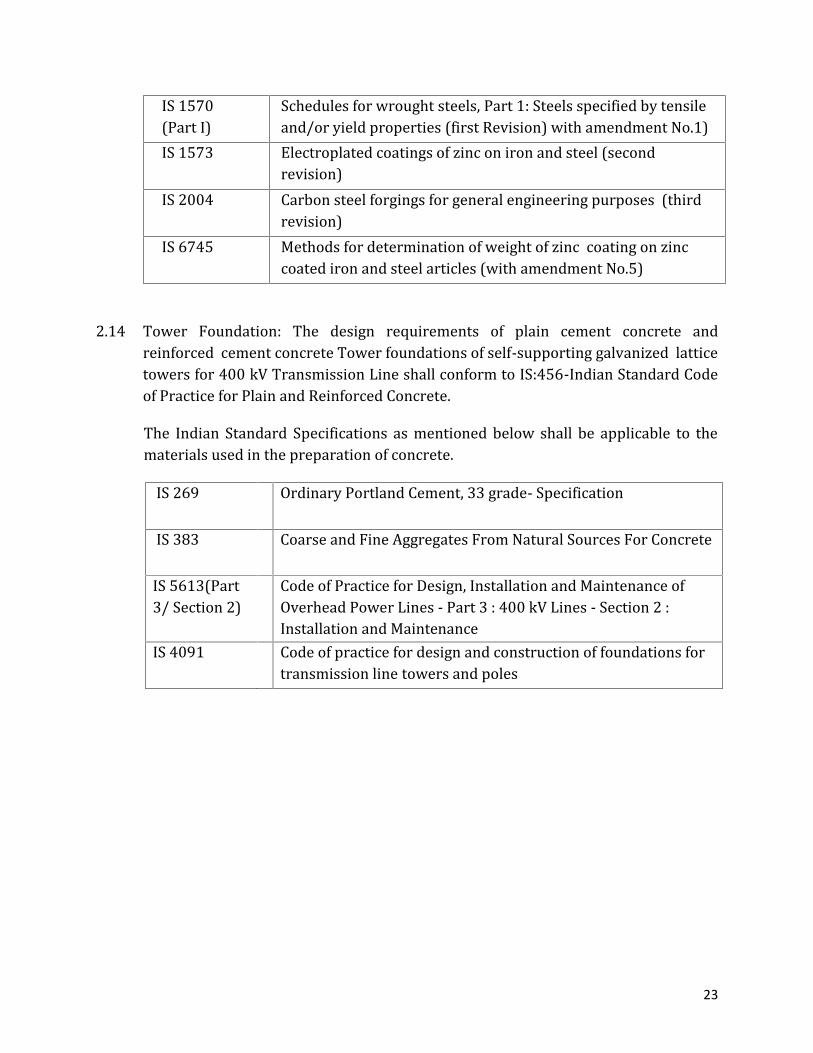
IS 1570(Part I) Schedules for wrought steels, Part 1: Steels specified by tensileand/or yield properties (first Revision) with amendment No.1)IS 1573 Electroplated coatings of zinc on iron and steel (secondrevision)IS 2004 Carbon steel forgings for general engineering purposes (thirdrevision)IS 6745 Methods for determination of weight of zinc coating on zinccoated iron and steel articles (with amendment No.5)2.14 Tower Foundation: The design requirements of plain cement concrete andreinforced cement concrete Tower foundations of self-supporting galvanized latticetowers for 400 kV Transmission Line shall conform to IS:456-Indian Standard Codeof Practice for Plain and Reinforced Concrete.The Indian Standard Specifications as mentioned below shall be applicable to thematerials used in the preparation of concrete.IS 269 Ordinary Portland Cement, 33 grade- Specification
IS 383 Coarse and Fine Aggregates From Natural Sources For ConcreteIS 5613(Part3/ Section 2) Code of Practice for Design, Installation and Maintenance ofOverhead Power Lines - Part 3 : 400 kV Lines - Section 2 :Installation and MaintenanceIS 4091 Code of practice for design and construction of foundations fortransmission line towers and poles

24
SECTION 3
INSULATORS
3.1 Insulators suitable for 400 kV over-head transmission lines shall be used. Theseshall be suitable for being installed directly in air suspended on the tower crossarms or anchored to the power cross arms of 400 kV D.C. line on suspension andtension towers. The ratings shall be 120 KN and 160 KN for discs in suspension andtension respectively. They shall be ball and socket type of porcelain or toughenedglass. Alternatively, long rod insulators of the same ratings may also be used.3.2 The insulators used shall conform to the following standards as applicable to theappropriate insulators.IEC 60120 Dimensions of ball and socket couplings of string insulator units.IS 137 Ready mixed paint, brushing, matt or eggshell flat, finishing, interiorto Indian Standard Colour as required. (Amendment no 3)IS 209 Zinc Ingot- Specification (Fourth Revision with amendment no. 2)IEC 60305 Characteristics of string insulatorsIS 1449 Methods of sampling of manganese oresIS 1473 Methods of chemical analysis of Manganese oresIEC 60318-6 Eacoustics - Simulators of human head and ear - Part 6: Mechanicalcoupler for the measurement on bone vibratorsIEC 60383 Insulators for overhead lines with a nominal voltage above 1 000 v-part 2: insulator strings and insulator sets for a.c. systems -definitions, test methods and acceptance criteriaIS 406 Method of Chemical Analysis of slab zincIEC 60575 Thermal Mechanical Endurance tests and Mechanical Endurance testsand Mechanical performance tests in string Insulator unitsIEC 60672 Specification for Ceramic and Glass Insulating materialsPart.I Definitions and classificationsPart.II Methods and testIS 731 Specification for porcelain insulators for over head lines (3.3 KV andabove)IS 814 Phosphor Bronze sheet, strip and foil

25
IS 1570 Specification for wrought steel for General Engineering purposeIS 1573 Electroplated coatings of zinc on iron and steelIS 2071(Part 1 and3) Methods of High Voltage TestingIS 14329 Malleable iron castingsIS 2486 Parts 1,2,3 and 4 specifications for insulator fittings for over headpower lines with nominal voltage greater than 1000 voltsIS 2629 Recommended practice for hot dip galvanizing of Iron and SteelIS 3188 Dimensions for disc insulatorsIS 6603 Stainless steel bars and flats (Amendments 1 to 4)IS 7811 Phosphor bronze rods and barsIS 7814 Phosphor rods and barsIS 8263 Method of radio interference tests on HV insulatorsIS 8269 Method of switching impulse Test on HV insulatorsIEC:60507 Salt Fog Pollution voltage withstand test.IEC:60815 Guide for the selection of insulators in respect of polluted conditions.ASTMC151-93- a Standard Test Method for Autoclave Expansion of Portland Cement.
ANSIC29-2 American National Standard for Insulators wet process porcelain andtoughened glass suspension type.IEC:60437 Methods of RIV test of HV insulatorsIEC:60372 Locking devicesIEC:60797 Residual strength of string insulator unit of glass or ceramic materialfor overhead line after mechanical damage of the dielectricIEC : 60433 Insulators for overhead lines with a nominal voltage above 1000 V -Ceramic insulators for a.c. systems- Characteristics of insulator unitsof the long rod type.3.3 Atmospheric Conditions: The materials offered shall be suitable for operation intropical climate and will be subject to the full rays of the sun and inclement weatherand should be able to withstand wide range of temperature variations. The humiditymay be as high as 100% during rainy season and as low as 10% during the dryseason.3.4 Markings: Each insulator shall be legibly and indelibly marked to show the
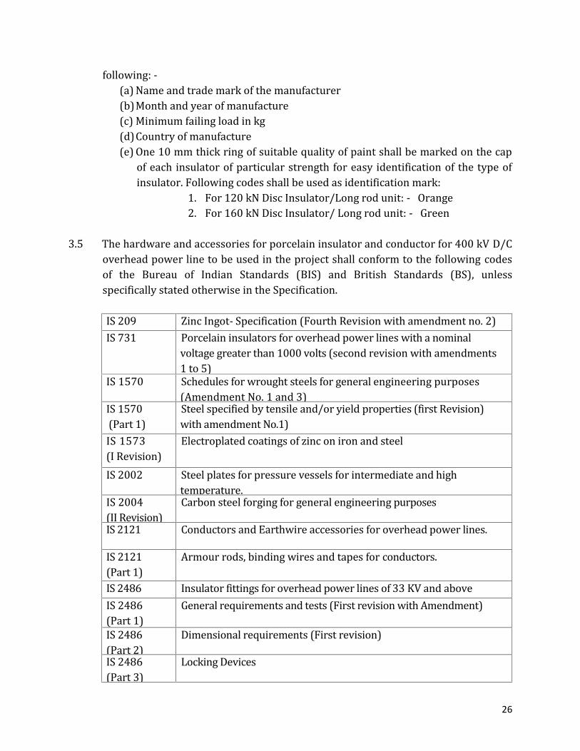
26
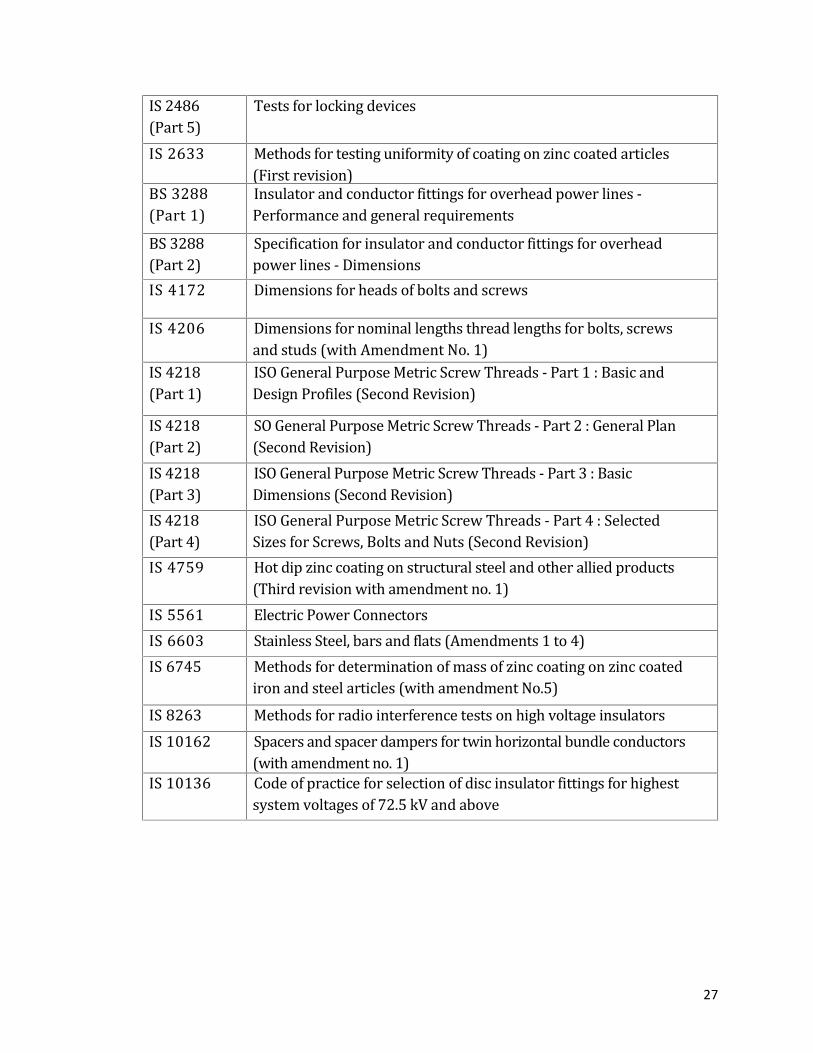
following: -(a) Name and trade mark of the manufacturer(b)Month and year of manufacture(c) Minimum failing load in kg(d)Country of manufacture(e) One 10 mm thick ring of suitable quality of paint shall be marked on the capof each insulator of particular strength for easy identification of the type ofinsulator. Following codes shall be used as identification mark:1. For 120 kN Disc Insulator/Long rod unit: - Orange2. For 160 kN Disc Insulator/ Long rod unit: - Green3.5 The hardware and accessories for porcelain insulator and conductor for 400 kV D/Coverhead power line to be used in the project shall conform to the following codesof the Bureau of Indian Standards (BIS) and British Standards (BS), unlessspecifically stated otherwise in the Specification.IS 209 Zinc Ingot- Specification (Fourth Revision with amendment no. 2)IS 731 Porcelain insulators for overhead power lines with a nominalvoltage greater than 1000 volts (second revision with amendments1 to 5)IS 1570 Schedules for wrought steels for general engineering purposes(Amendment No. 1 and 3)IS 1570(Part 1) Steel specified by tensile and/or yield properties (first Revision)with amendment No.1)IS 1573(I Revision) Electroplated coatings of zinc on iron and steelIS 2002 Steel plates for pressure vessels for intermediate and hightemperature.IS 2004(II Revision) Carbon steel forging for general engineering purposesIS 2121 Conductors and Earthwire accessories for overhead power lines.IS 2121(Part 1) Armour rods, binding wires and tapes for conductors.IS 2486 Insulator fittings for overhead power lines of 33 KV and aboveIS 2486(Part 1) General requirements and tests (First revision with Amendment)IS 2486(Part 2) Dimensional requirements (First revision)IS 2486(Part 3) Locking Devices
27
IS 2486(Part 5) Tests for locking devicesIS 2633 Methods for testing uniformity of coating on zinc coated articles(First revision)BS 3288(Part 1) Insulator and conductor fittings for overhead power lines -Performance and general requirementsBS 3288(Part 2) Specification for insulator and conductor fittings for overheadpower lines - DimensionsIS 4172 Dimensions for heads of bolts and screwsIS 4206 Dimensions for nominal lengths thread lengths for bolts, screwsand studs (with Amendment No. 1)IS 4218(Part 1) ISO General Purpose Metric Screw Threads - Part 1 : Basic andDesign Profiles (Second Revision)IS 4218(Part 2) SO General Purpose Metric Screw Threads - Part 2 : General Plan(Second Revision)IS 4218(Part 3) ISO General Purpose Metric Screw Threads - Part 3 : BasicDimensions (Second Revision)IS 4218(Part 4) ISO General Purpose Metric Screw Threads - Part 4 : SelectedSizes for Screws, Bolts and Nuts (Second Revision)IS 4759 Hot dip zinc coating on structural steel and other allied products(Third revision with amendment no. 1)IS 5561 Electric Power ConnectorsIS 6603 Stainless Steel, bars and flats (Amendments 1 to 4)IS 6745 Methods for determination of mass of zinc coating on zinc coatediron and steel articles (with amendment No.5)IS 8263 Methods for radio interference tests on high voltage insulatorsIS 10162 Spacers and spacer dampers for twin horizontal bundle conductors(with amendment no. 1)IS 10136 Code of practice for selection of disc insulator fittings for highestsystem voltages of 72.5 kV and above

28
SECTION 4
CONDUCTOR
4.1 ACSR conductor MOOSE shall be used as Power conductors on 400kV Double CircuitTransmission Lines. The conductor shall conform to the followingIndian/International Standards, which shall mean latest revisions, with amendmentchanges adopted and published, unless specifically stated otherwise in theSpecification.IS 209 Zinc Ingot- Specification (Fourth Revision with amendment no. 2)BS 215: 1970 Aluminium conductors, steel reinforcedIS 398 (Part-1) Specification for Aluminium Conductors for OverheadTransmission Purposes: Aluminium Stranded Conductors.IS 398 (Part-2) Aluminium conductors, galvanized steel reinforcedIS 398 (Part-5) Aluminium conductors galvanized steel reinforced for Extra highvoltage (400 kV and above)IS 1521 Method of Tensile Testing of Steel Wire.IS 1778 Reels and drums for bare conductors (First Revision)IS 5484 EC grade aluminium rod produced by continuous casting androlling ( second revision with amendment no. 1)IS 2629 Recommended practice for hot dip Galvanizing of Iron and Steel.IS 2633 Methods of testing uniformity of Coating on Zinc CoatedarticlesIS 4826 Hot dipped Galvanised coating on round steel wiresIS 5484 EC grade Aluminium rod produced by continuous casting androlling (second revision).IS 6745 Methods of Determination of Weight of Zinc Coating on ZincCoated Iron and Steel Articles.IS 7623 Lithium base Grease for Industrial purposes (First Revision)IS 8263 Method of Radio Interference tests on high voltage insulators.IEC: 60888 Zinc Coated Steel Wires for Stranded ConductorsIEC 60889 Hard Drawn Aluminium Wires for Overhead Line Conductors.4.2 The Power conductor accessories that are required shall be suitable forTWINMOOSE ACSR conductor and the ground wire conductor accessories and

29
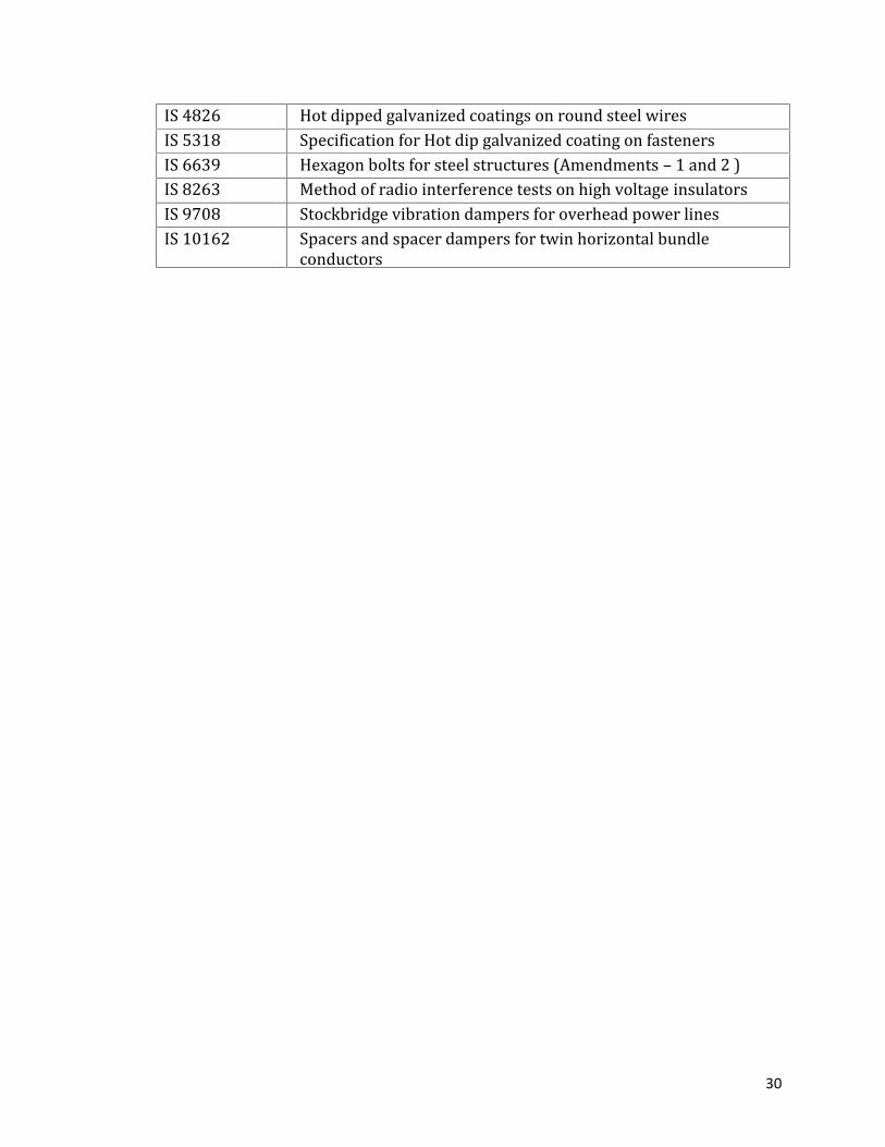
hardware fittings that are required shall be suitable for 7/3.66mm GSS wire. Thefittings and accessories of Power conductor and Ground wire shall comply in allrespects with the latest edition of the following codes of the Bureau of IndianStandards (BIS) and British Standards (BS) or any other equivalent authoritativestandard.IS 209 Zinc Ingot- SpecificationBS 970 (Part 1) General Instruction and testing procedures specificrequirements for carbon Manganese alloy and stainless steels.IS 1327 Method of determination of mass of tin coating on Tinplate(Second revision)IS 1363 Hexagon head bolts, screws and nutsIS 1363 (Part 1) Hexagon head bolts (Second Revision with Amendment No.1)IS 1363 (Part 2) Hexagon head screws (Second Revision with AmendmentNo.1)IS 1363 (Part 3) Hexagon head screws (Second Revision with AmendmentNo.1)IS 1367 Technical supply conditions for threaded steel fasteners.IS 1367(Part 1) Technical supply conditions for threaded steel fasteners.IS 1367(Part 2) Product grades and tolerance (Second Revision)IS 1367 (Part 3) Mechanical properties and test methods for bolts screws andstuds with full lead ability (Second revision)IS 1573 Electroplated coatings of zinc on Iron and Steel (First revision)IS 2004 Carbon steel forgings for general engineering purposes(Second Revision.)IS 2121 Conductors and Earth wire accessories for overhead powerlinesIS 2121 (Part 1) Armour rods, binding wires and tapes for conductorsIS 2121 (Part 2) Mid span joints and repair sleeves for conductorsIS 2486 Insulator fittings for overhead power lines of 3.3 KV and aboveIS 2486 (Part 3) General Requirements and tests (First Revision withAmendment No.1)IS 2486 (Part 2) Dimensional Requirements (First Revision)IS 2486 (Part 3) Locking devicesIS 2486 (Part 4) Tests for locking devicesIS 2629 Recommended practice for hot dip galvanizing of Iron andSteel.IS 2633 Methods of testing uniformity of coating on Zinc coatedarticles (First Revision)IS 3138 Specification for Hexagonal Bolts and NutsIS 4218 Specification for Metric Screw Threads
30
IS 4826 Hot dipped galvanized coatings on round steel wiresIS 5318 Specification for Hot dip galvanized coating on fastenersIS 6639 Hexagon bolts for steel structures (Amendments – 1 and 2 )IS 8263 Method of radio interference tests on high voltage insulatorsIS 9708 Stockbridge vibration dampers for overhead power linesIS 10162 Spacers and spacer dampers for twin horizontal bundleconductors

31
SECTION 5
GROUND WIRE5.1 This Galvanized Steel Stranded ground wire of 7/3.66 mm size and 981 N/sq.mmquality (grade 3 as per IS 2141) for the purpose of earthing and protection of powertransmission lines. The ground wire shall consist of standard galvanized steel wires.The GSS wire is to be used for the overhead protection of 400 kV Double circuit.5.2 The ground wire shall comply in all respects with the following codes of the Bureauof Indian Standards (BIS) and British Standard.IS 279 Galvanized steel wire for telegraph and telephone purposes (thirdrevision with amendment no. 2)IS 209 Zinc Ingot- SpecificationIS 398(Part 2) Aluminium conductors for overhead transmission purposes: Part 2Aluminium conductors, galvanized steel reinforced (third revision withamendment no. 1)IS 398(Part 5) Aluminium conductors for overhead transmission purposes: Part 5Aluminium conductors - galvanized steel reinforced for extra highvoltage (400 kV and above) (first revision with amendment no. 2)IS 1608 Mechanical testing of metals - Tensile Testing (third revision)IS 1755 Method of wrapping test of steel wires (first revision with amendmentno. 1)IS 1778 Reels and drums for Bare conductors (first revision with amendmentno. 1)IS 2141 Hot Dip Galvanized Stay Strand (fourth revision with amendment no.1)IS 2363 Glossary of terms relating to wire ropes (First Revision)IS 2500(Part 1) Sampling Inspection Procedures - Part 1 : Attribute Sampling PlansIndexed by Acceptable Quality Limit (AQL) for Lot-by-Lot InspectionIS 2629 Recommended practice for hot dip galvanizing of iron and steelIS 2633 Method of testing uniformity of coating on zinc Coated articlesIS 4826 Hot dipped galvanized coatings on round steel wires (first revisionwith amendment No.1)IS 3635 Methods of test for resistance of metallic electrical resistanceIS 5714 Method of measurement of resistivity of metallic materialsIS 6594 Technical supply conditions for steel wire rope and strands
32
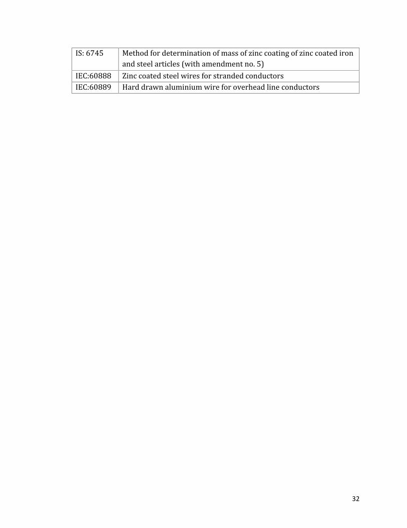
IS: 6745 Method for determination of mass of zinc coating of zinc coated ironand steel articles (with amendment no. 5)IEC:60888 Zinc coated steel wires for stranded conductorsIEC:60889 Hard drawn aluminium wire for overhead line conductors
33
SECTION 6
OPTICAL GROUND WIRE6.1 The OPTICAL GROUND WIRE (OPGW) cable comprises a ground wire (containingaluminium and steel) with optical fibres in the core or first layer. The OPGW cablereplaces the normal ground wires and therefore has to fulfill all the electrical andenvironmental requirements which affect the ground wire. The fittings, accessoriesto be supplied shall also be suitable for the OPGW type.6.2 OPGW Cable: The OPGW cable construction shall comply with IEEE 1138 and IECpublication 61396. The cable construction shall conform to the applicable clauses ofIEC 61089 related to stranded conductors and following electrical and mechanicalcharacteristics of OPGW:Everyday Tension: < 20% of UTS of OPGWDC Resistance at 20 deg. C: < 1.0 Ohm/kMShort circuit current: > 6.32 kA for 1.0 sec6.3 All Dielectric Self- Supporting (ADSS) Cable: ADSS cable shall be used for interconnecting OPGW cable with the terminal gantry at the substation/powerhouse/office. The ADSS cable including various clamps, terminals and accessoriesshall withstand aeolin vibrations and possible galloping and touching of the phaseconductors. In order to reduce the possibility of mechanical failure, the erosion ofthe cable sheath due to “dry banding effect” shall be minimized.6.4 Fibre Types : Dual-Window Single Mode (DWSM) optical fibres of 24 Nos. shall beprovided in the cable. The fibres shall be entirely suitable for splicing by means ofnormal fusion splicing techniques. The fibre shall be manufactured from high gradesilica and doped as necessary to provide the required transmission performance.6.5 The chemical composition of the fibres shall be specially designed to minimize theeffect of hydrogen on the transmission properties. The fibre cable life expectancyshall be at least 25 years.6.6 The material shall conform to the following Indian/International Standards, whichshall mean latest revisions, amendments/changes adopted and published unlessotherwise specified herein.
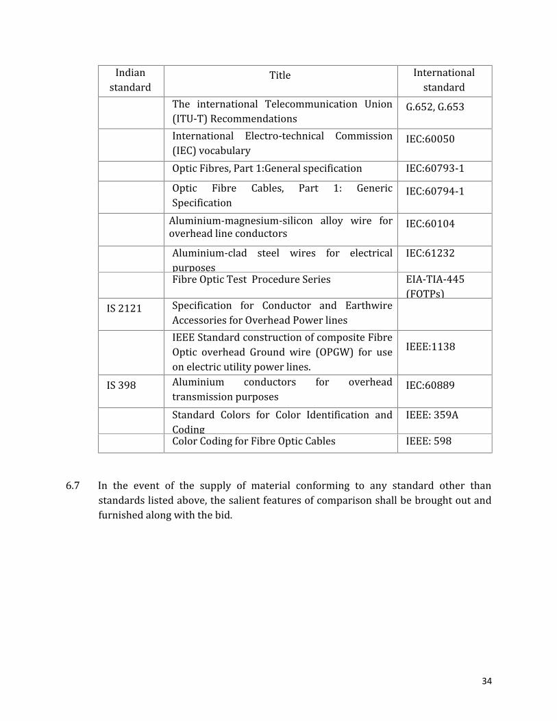
34
Indianstandard Title InternationalstandardThe international Telecommunication Union(ITU-T) Recommendations G.652, G.653International Electro-technical Commission(IEC) vocabulary IEC:60050Optic Fibres, Part 1:General specification IEC:60793-1Optic Fibre Cables, Part 1: GenericSpecification IEC:60794-1Aluminium-magnesium-silicon alloy wire foroverhead line conductors IEC:60104Aluminium-clad steel wires for electricalpurposes IEC:61232Fibre Optic Test Procedure Series EIA-TIA-445(FOTPs)IS 2121 Specification for Conductor and EarthwireAccessories for Overhead Power linesIEEE Standard construction of composite FibreOptic overhead Ground wire (OPGW) for useon electric utility power lines. IEEE:1138IS 398 Aluminium conductors for overheadtransmission purposes IEC:60889Standard Colors for Color Identification andCoding IEEE: 359AColor Coding for Fibre Optic Cables IEEE: 598
6.7 In the event of the supply of material conforming to any standard other thanstandards listed above, the salient features of comparison shall be brought out andfurnished along with the bid.

35
SECTION 7
ERECTION, TESTING AND COMMISSIONING7.1 This section covers erection, testing and commissioning of the transmission lines,handling, transportation and distribution of all line materials to the respective worksite.7.2 Except where otherwise specified or implied, the erection, testing shall conform tothe provisions of IS 5613 (Part 3, Section - 2).7.3 The commissioning shall be carried out as per Manual on Commissioning procedurefor Transmission lines, CBI&P Publication no. 292.7.4 The Indian Standard Specifications mentioned below or equivalent InternationalStandards shall be applicable to the materials and processes used in executing theworks.IS 383 Course and Fine Aggregates from Natural Sources forConcrete.IS 1200 IS 1200 Method of Measurement of Building and Civilengineering Works (Relevant Parts)IS 456 Plain and Reinforced Concrete - Code of Practice (thirdrevision with amendment no. 4)IS 2502 Code of Practice for Bending and Fixing of Bars forConcrete Reinforcement.IS 3043 Code of Practice for Earthing.IS 3764 Safety Code for Excavation Work.IS 4081 Safety Code of Blasting and Related Drilling Operation.IS 4091 Code of Practice for Design and Construction ofFoundations for Transmission Line Towers and Poles.IS 1080 Code of Practice for Design and Construction ofShallow Foundations in Soils (other than Raft, Ring andShell)IS 1498 Classification and Identification of Soils for GeneralEngineering Purposes.IS 1892 Code of Practice for Subsurface Investigation forFoundation.IS 1904 Code of Practice for Design and Construction ofFoundation in Soils: General Requirements.

36
IS 2131 Method of Standard Penetration Test for SoilsIS 2132 Code of Practice for Thin Walled Tube Sampling ofSoils.IS 2720 Method of Test for Soils (Relevant Parts)IS 2809 Glossary of Terms and Symbols Relating to SoilEngineering.IS 2911 Code of Practice for Design and Construction of PileFoundations (Relevant Parts)IS 3025 Methods of sampling and test (physical and chemical)for water and wastewater (Relevant Parts)IS 4078 Code of Practice for Indexing and Storage of DrillCores.IS 4434 Code of Practice for In-situ Vane Shear Test for SoilsIS 4453 Subsurface Exploration by Pits, Trenches, Drifts andShafts - Code of PracticeIS 4464 Code of Practice for Presentation of DrillingInformation and Core Description in FoundationInvestigationIS 4968(Part 2) Method for subsurface sounding for soils: Part 2Dynamic method using cone and bentonite slurryIS 5313 Guide for Core Drilling ObservationsIS 6403 Code of Practice for Determination of AllowableBearing Pressure on Shallow Foundation.IS 6926 Diamond Core Drilling - Site Investigation for RiverValley Projects - Code of Practice (first revision)IS 6935 Method of Determination of Water Level in a BoreHole.IS 7422 Symbols and Abbreviations for Use in Geological Maps,Sections and Subsurface Exploratory Logs (RelevantParts)IS 8009(Part –1) Code of practice for calculation of settlements offoundations: Part 1 Shallow foundations subjected tosymmetrical static vertical loads (with amendment no.3)IS 8764 Method for Determination of Point Load StrengthIndex of Rocks.IS 9143 Method for Determination of Unconfined CompressiveStrength of Rock Materials.
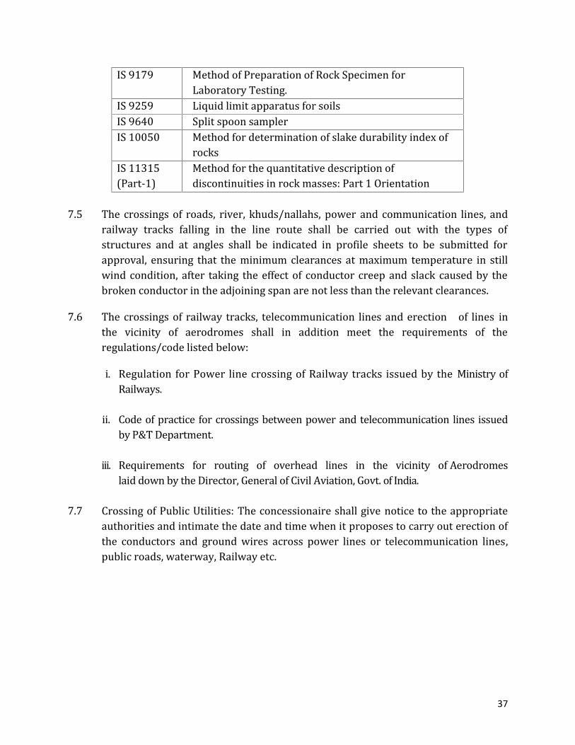
37
IS 9179 Method of Preparation of Rock Specimen forLaboratory Testing.IS 9259 Liquid limit apparatus for soilsIS 9640 Split spoon samplerIS 10050 Method for determination of slake durability index ofrocksIS 11315(Part-1) Method for the quantitative description ofdiscontinuities in rock masses: Part 1 Orientation7.5 The crossings of roads, river, khuds/nallahs, power and communication lines, andrailway tracks falling in the line route shall be carried out with the types ofstructures and at angles shall be indicated in profile sheets to be submitted forapproval, ensuring that the minimum clearances at maximum temperature in stillwind condition, after taking the effect of conductor creep and slack caused by thebroken conductor in the adjoining span are not less than the relevant clearances.7.6 The crossings of railway tracks, telecommunication lines and erection of lines inthe vicinity of aerodromes shall in addition meet the requirements of theregulations/code listed below:i. Regulation for Power line crossing of Railway tracks issued by the Ministry ofRailways.ii. Code of practice for crossings between power and telecommunication lines issuedby P&T Department.iii. Requirements for routing of overhead lines in the vicinity of Aerodromeslaid down by the Director, General of Civil Aviation, Govt. of India.7.7 Crossing of Public Utilities: The concessionaire shall give notice to the appropriateauthorities and intimate the date and time when it proposes to carry out erection ofthe conductors and ground wires across power lines or telecommunication lines,public roads, waterway, Railway etc.

38
Part- BSUBSTATIONS
39
SECTION 8
AIR INSULATED SUBSTATION (AIS)
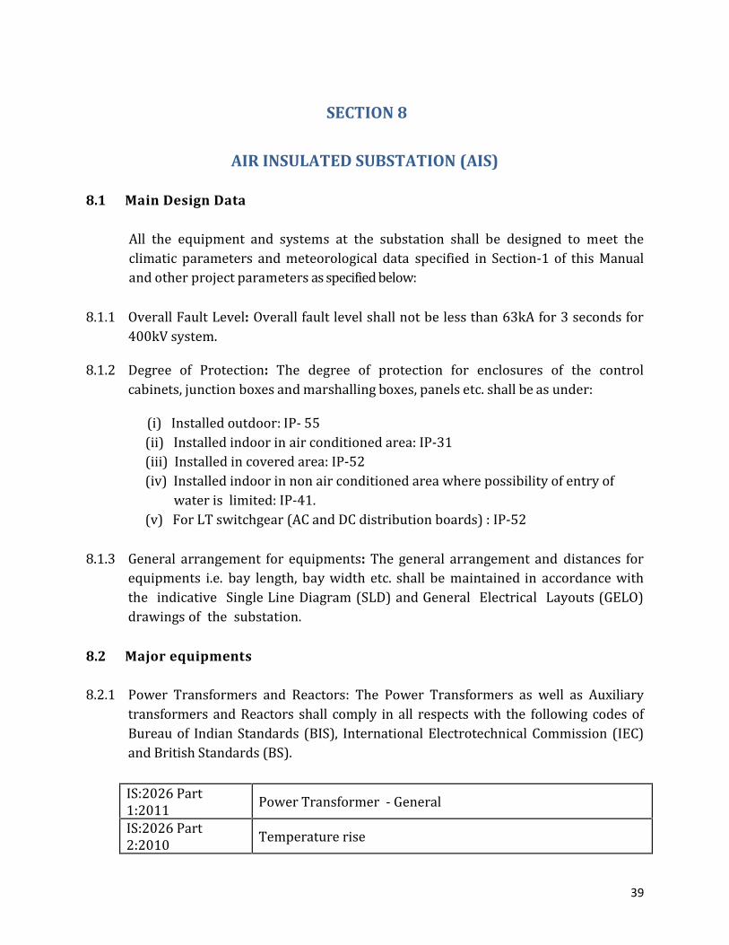
8.1 Main Design DataAll the equipment and systems at the substation shall be designed to meet theclimatic parameters and meteorological data specified in Section-1 of this Manualand other project parameters as specified below:8.1.1 Overall Fault Level: Overall fault level shall not be less than 63kA for 3 seconds for400kV system.8.1.2 Degree of Protection: The degree of protection for enclosures of the controlcabinets, junction boxes and marshalling boxes, panels etc. shall be as under:(i) Installed outdoor: IP- 55(ii) Installed indoor in air conditioned area: IP-31(iii) Installed in covered area: IP-52(iv) Installed indoor in non air conditioned area where possibility of entry ofwater is limited: IP-41.(v) For LT switchgear (AC and DC distribution boards) : IP-528.1.3 General arrangement for equipments: The general arrangement and distances forequipments i.e. bay length, bay width etc. shall be maintained in accordance withthe indicative Single Line Diagram (SLD) and General Electrical Layouts (GELO)drawings of the substation.8.2 Major equipments8.2.1 Power Transformers and Reactors: The Power Transformers as well as Auxiliarytransformers and Reactors shall comply in all respects with the following codes ofBureau of Indian Standards (BIS), International Electrotechnical Commission (IEC)and British Standards (BS).
IS:2026 Part1:2011 Power Transformer - GeneralIS:2026 Part2:2010 Temperature rise

40
IS:2026 Part3:2009 Insulation levels, dielectric tests and external clearances in airIS:2026 Part4:1997 Terminal markings, tappings and connectionsIS:2026 Part5:2011 Ability to withstand short circuitIS:2026 Part7:2009 Loading guide for oil - immersed Power TransformersIS:2026 Part8:2009 Application guideIS:2026 Part10:2009 Determination of sound levelsIEC 60076 Part 1( 2011-04 ) GeneralIEC 60076 Part 2( 2011-02 ) Temperature riseIEC 60076 Part 3( 2013-07 ) Insulation levels, dielectric tests and external clearances in airIEC 60076 Part 4( 2002-06 ) Guide to lightning impulse and switching impulse testing –Power Transformers and reactorsIEC 60076 Part 5( 2006-02 ) Ability to withstand short circuitIEC 60076 Part 6( 2007-12 ) ReactorsIEC 60076 Part 7( 2005-12 ) Power Transformer - Loading guide for oil-immersed PowerTransformersIEC 60076 Part 8( 1997-10 ) Application guideIEC 60076 Part 10( 2001-05 ) Determination of sound levelsIEC 60076 Part 11( 2004-05 ) Dry-type transformersIEC 60076 Part 12( 2008-11 ) Loading guide for dry - type Power TransformersIEC 60076 Part 13( 2006-05 ) Power Transformer - Protected liquid filled transformersIEC 60076 Part 14( 2013-09 ) Guide for the design and application of liquid-immersed PowerTransformers using high-temperature insulation materialsIEC 60076 Part 15( 2008-02 ) Gas-filled-type Power TransformersIEC 60076 Part 16( 2011-08 ) Power Transformer - Transformers for Wind TurbineapplicationsIEC 60076 Part 18( 2012-07 ) Measurement of frequency response

41
IEC 60076 Part 19( 2013-03 ) Rules for the determination of uncertainties in themeasurement of losses in Power Transformers and reactorsIEC 60076 Part 21( 2011-12 ) Standard requirements terminology and test code for step-voltage regulatorsBS EN 60076 Part1: 2011 Power Transformer-GeneralBS EN 60076 Part2:2011 Temperature rise for liquid immersed transformerBS EN 60076 Part3:2013 Insulation levels dielectric tests and external clearances in airBS EN 60076 Part4 :2002 Guide to lightning impulse and switching impulse testing –Power Transformers and reactorsBS EN 60076 Part5 :2006 Ability to withstand short circuitBS EN 60076 Part6:2008 ReactorsBS EN 60076 Part7:2005 Loading guide for oil-immersed Power TransformersBS EN 60076 Part8 :1997 Application guideBS EN 60076 Part10: 2005 Determination of sound levelsBS EN 60076 Part11:2004 Dry-type transformersBS EN 60076 Part12:2011 Loading guide for dry-type Power TransformersBS EN 60076 Part13:2006 Self protected liquid filled transformersBS EN 60076 Part14:2013 Liquid-immersed Power Transformers using high-temperatureinsulation materialsBS EN 60076 Part16:2011 Transformers for Wind Turbine applicationsBS EN 60076 Part18:2012 Measurement of frequency responseIS:3639-1966(reaffirmed 2001 ) Specification for fitting and accessories for PowerTransformersBS EN :1014 Part-1:2010 Wood preservatives. Creosote and creosoted timber. Methodsof sampling and analysis. Procedure for sampling creosoteBS EN :1014 Part-2:2010 Wood preservatives. Creosote and creosoted timber. Methodsof sampling and analysis. Procedure for obtaining a sample ofcreosote from creosoted timber for subsequent analysisBS EN :1014 Part-3:2010 Wood preservatives. Creosote and creosoted timber. Methodsof sampling and analysis. Determination of the benzo(a)

42
pyrene content of creosoteBS EN :1014 Part-4:2010 Wood preservatives. Creosote and creosoted timber. Methodsof sampling and analysis. Determination of the water-extractable phenols content of creosoteIS 6600-1972(reaffirmed 2001 ) Guide for loading of oil-immersed transformerIS:335: 1993(reaffirmed 2005 ) New insulating oils- specificationBS :148 2009 Reclaimed mineral insulating oil for transformers andswitchgear specificationBS :148 Part -1:2010 Metallic materials. Charpy pendulum impact test. Test methodBS :148 Part -2:2008 Metallic materials. Charpy pendulum impact test. Verificationof testing machinesBS :148 Part -3:2008 Metallic materials. Charpy pendulum impact test. Preparationand characterization of Charpy V-notch test pieces for indirectverification of pendulum impact machinesIEC: 60296 Fluids for electro-technical applications. Unused mineralinsulating oils for transformers and switchgearIS:2099:1986(reaffirmed 2003 ) Bushings for alternating voltages above 1000 voltsIEC 60137: 2003-2008 Insulated bushings for alternating voltages above 1000vIS:3637-1966(reaffirmed 2007 ) Specification for gas -operated relays8.2.2 Circuit Breakers: The duty cycle of Circuit Breakers installed in 420 / 245 / 145 kVSystem shall be “O-0.3 sec-CO-3 min-CO”. The Surge Arrester shall be suitable forsuch circuit breaker duties in the system. Circuit Breakers shall have the followingparameters:Voltage level 400 kV 220 kV 132 kVBreak Time (ms) 40 50 60Auto reclosing Single/ThreePhase Single/ThreePhase Three Phase
The Circuit Breakers shall comply in all respects with the following codes of theBureau of Indian Standards (BIS) and International Electrotechnical Commission(IEC):IS 13118: 1991(reaffirmed 2002) Specification for high voltage alternating current circuitbreaker
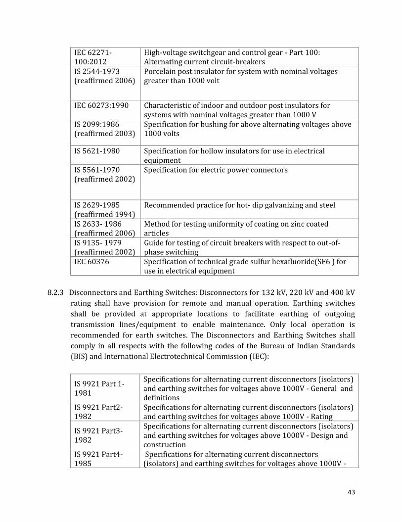
43
IEC 62271-100:2012 High-voltage switchgear and control gear - Part 100:Alternating current circuit-breakersIS 2544-1973(reaffirmed 2006) Porcelain post insulator for system with nominal voltagesgreater than 1000 voltIEC 60273:1990 Characteristic of indoor and outdoor post insulators forsystems with nominal voltages greater than 1000 VIS 2099:1986(reaffirmed 2003) Specification for bushing for above alternating voltages above1000 voltsIS 5621-1980 Specification for hollow insulators for use in electricalequipmentIS 5561-1970(reaffirmed 2002) Specification for electric power connectorsIS 2629-1985(reaffirmed 1994) Recommended practice for hot- dip galvanizing and steelIS 2633- 1986(reaffirmed 2006) Method for testing uniformity of coating on zinc coatedarticlesIS 9135- 1979(reaffirmed 2002) Guide for testing of circuit breakers with respect to out-of-phase switchingIEC 60376 Specification of technical grade sulfur hexafluoride(SF6 ) foruse in electrical equipment8.2.3 Disconnectors and Earthing Switches: Disconnectors for 132 kV, 220 kV and 400 kVrating shall have provision for remote and manual operation. Earthing switchesshall be provided at appropriate locations to facilitate earthing of outgoingtransmission lines/equipment to enable maintenance. Only local operation isrecommended for earth switches. The Disconnectors and Earthing Switches shallcomply in all respects with the following codes of the Bureau of Indian Standards(BIS) and International Electrotechnical Commission (IEC):IS 9921 Part 1-1981 Specifications for alternating current disconnectors (isolators)and earthing switches for voltages above 1000V - General anddefinitionsIS 9921 Part2-1982 Specifications for alternating current disconnectors (isolators)and earthing switches for voltages above 1000V - RatingIS 9921 Part3-1982 Specifications for alternating current disconnectors (isolators)and earthing switches for voltages above 1000V - Design andconstructionIS 9921 Part4-1985 Specifications for alternating current disconnectors(isolators) and earthing switches for voltages above 1000V -

44
type test and routine testIEC 60694 Common specifications for high voltage switchgear andcontrol gear standardsIEC 6227-102 High voltage switchgear and control gear- Part 102:Alternating current disconnectors and earthing switchesIS 2544-1973(reaffirmed 2006) Porcelain post insulator for system with nominal voltagesgreater than 1000 voltIEC 60273 Characteristic of indoor and outdoor post insulators forsystems with nominal voltages greater than 1000 VIS 5561-1970(reaffirmed 2002) Specifications for electric power connectorsIS 2629-1985(reaffirmed 1994) Recommended practice for hot- dip galvanizing and steelIS 2633- 1986(reaffirmed 2006) Method for testing uniformity of coating on zinc coated articles8.2.4 Current Transformers: The rated currents and ratios, the number of secondarywinding (protection and metering), accuracy class, burden, secondary windingresistance, knee point voltage and excitation current shall be in accordance withthe requirements of the protection system. The accuracy class for meteringwinding shall be equal to or better than the accuracy class of the meter specified inthe Central Electricity Authority (Installation and operation of Meters) Regulations,2010.The Current Transformer shall comply in all respects with the following codes ofBureau of Indian Standards (BIS), International Electro technical Commission (IEC)and British Standard (BS) specifications:IS 2705 Part1:1992 Current transformers specifications - General requirement
IS 2705 Part2:1992 Current transformers specifications - Measuring currenttransformersIS 2705 Part3:1992 Current transformers specifications - Protective currenttransformersIS 2705 Part4:1992 Current transformers specifications - Protective currenttransformer for special purpose applicationsBS EN 61869 Part1 Instrument transformers: General requirements

45
BS EN 61869 Part2 Instrument transformers: Additional requirements forcurrent transformersBS EN 61869 Part4 Instrument transformers: Additional requirements forcombined transformersIS:335: 1993(reaffirmed 2005 ) New insulating oils - specificationsIEC: 60296 2003-11 Fluids for electro-technical applications - Unused mineralinsulating oils for transformers and switchgearIS 2099:1986(reaffirmed 2003 ) Specification for bushing for above alternating voltagesabove 1000 voltsIEC 62155 Hollow pressurized and unpressurized ceramic and glassinsulators for use in electrical equipment with rated voltagesgreater than 1 000 VIS 5621-1980 Specification for hollow insulators for use in electricalequipmentIEC 62155 Hollow pressurized and unpressurized ceramic and glassinsulators for use in electrical equipment with rated voltagesgreater than 1 000 VIS 2544-1973(reaffirmed 2006 ) Porcelain post insulator for system with nominal voltagesgreater than 1000 voltBS 3297 Part1 Post Insulators of Ceramic Material or Glass for NominalVoltages Greater Than 1000 V Part 1: Methods of TestBS 3297 Part2 Characteristics of Indoor and Outdoor Post Insulators forSystems with Nominal Voltages Greater than 1000 VBS 3297 Part3 Post Insulators of Ceramic Material or Glass for NominalVoltages Greater Than 1000 V Part 3: Guide to InsulatorPracticeIEC 60168 Tests on indoor and outdoor post insulators of ceramicmaterial or glass for systems with nominal voltages greaterthan 1000 VIS 2629-1985(reaffirmed 1994 ) Recommended practice for hot- dip galvanizing and steelIS 2633- 1986(reaffirmed 2006 ) Method for testing uniformity of coating on zinc coatedarticles8.2.5 Voltage/Capacitor Voltage Transformers: The number of secondary winding(protection or metering), accuracy class and burden shall be in accordance with therequirements of the protection system. The accuracy class for metering winding

46
shall be equal to or better than the accuracy class of the meter specified in theCentral Electricity Authority (Installation and Operation of Meters) Regulations,2010. The capacitance of CVT shall match the PLCC requirements.The Voltage/Capacitor Voltage Transformer shall comply in all respects with thefollowing codes of the Bureau of Indian Standards (BIS), British Standards (BS) andInternational Electrotechnical Commission (IEC):IS 3156 Part 1 Voltage transformer specifications - General requirementsIS 3156 Part2 Voltage transformer specifications -Measuring voltagetransformerIS 3156 Part 3 Voltage transformer specifications -Protective voltagetransformerIS 3156 Part 4 Voltage transformer specifications -Capacitive voltagetransformerBS EN 61869-Part3 Instrument transformers. Additional requirements forinductive voltage transformersBS EN 61869-Part 4 Instrument transformers - Additional requirements forcombined transformersBS EN 61869-Part5 Instrument transformers - Additional requirements forcapacitor voltage transformersIS 9859 Part1 Code and practice for installation and maintenance of outdoorpower line carrier equipment -Line trapIS 9859 Part2 Code and practice for installation and maintenance of outdoorpower line carrier equipment -Coupling devicesIS 9859 Part3 Code and practice for installation and maintenance of outdoorpower line carrier equipment -Coupling capacitor/capacitorvoltage transformer
8.2.6 Surge Arresters: Station class, heavy duty, gapless metal oxide (ZnO) type S urgeArresters shall be provided. The rated voltage, minimum Continuous OperatingVoltage (COV), energy handling capability, nominal discharge current and othercharacteristics of a Surge Arrester shall be chosen in accordance with power

47
system requirements. Surge Arresters shall be provided at locations as per GeneralElectrical Layout (GELO). A leakage current monitor with surge counter shall beprovided with each surge arrester.The Surge Arresters shall comply in all respects with the following codes of theBureau of Indian Standards (BIS) and International Electrotechnical Commission(IEC):IS 3070 Part3 Lightning arrester for alternating current systemspecifications - Metal oxide lightning arrester without gapsIEC 60099-Part4 Surge Arresters - Part 4: Metal-oxide surge arresters withoutgaps for a.c. systemsIEC 60099-Part5 Surge Arresters - Selection and application recommendationsIEC 60099-Part6 Surge Arresters containing both series and parallel gappedstructures- rated 52kV and lessIEC 60099-Part8 Surge Arresters - Metal-oxide surge arresters with externalseries gap (EGLA ) for overhead transmission anddistribution lines of a.c. systems above 1 kVIEC 60099-Part9 Surge Arresters - Metal-oxide surge arresters without gapsfor HVDC converter stationsIS 2544-1973(reaffirmed 2006) Porcelain post insulator for system with nominal voltagesgreater than 1000 voltIEC 60273 Characteristic of indoor and outdoor post insulators forsystems with nominal voltages greater than 1000 VIS 5621-1980 Specifications for hollow insulators for use in electricalequipmentIEC 62155 Hollow pressurized and unpressurized ceramic and glassinsulators for use in electrical equipment with rated voltagesgreater than 1000 VIS 5561-1970(reaffirmed 2002) Specifications for electric power connectorsIS 2629-1985(reaffirmed 1994) Recommended practice for hot- dip galvanizing and steelIS 2633- 1986(reaffirmed 2006 ) Method for testing uniformity of coating on zinc coatedarticles

48
8.2.7 Line Trap: A line trap is intended for insertion in a high voltage powertransmission line between the point of connection of carrier frequency signals andadjacent power system elements such as bus bars, transformers etc.The Line Trap shall comply in all respects with the following codes of the Bureau ofIndian Standards (BIS), British Standards (BS) and International ElectrotechnicalCommission (IEC):IS:8792 Line traps for power systems-specificationBS 4996 Specification for Line traps for power line carrier systemsIEC:60353 Line trap for AC power systemIS:8793 Line traps for AC power systems- methods of tests
8.3 System8.3.1 Auxiliary supply: AC and DC distribution system shall be so designed as to meet therequirement of the substation in accordance with the Central Electricity Authority(Technical Standards for Connectivity to the Grid) Amended Regulations, 2013.Computation of capacity of battery set in attended substations or switchyardsshall be as given bellow: Where standbybattery is provided(in hours) Where standbybattery is notprovided (in hours)Steady and continuousload 3 6Emergency lightingloads 1 2
8.3.2 Support structure / Ground clearance: All the support structures shall be galvanizedas per the relevant codes and standards. Minimum vertical distance from thebottom of the lowest porcelain part of the bushing, porcelain enclosures orsupporting insulators to the bottom of the equipment base, where it rests on thefoundation pad, shall be as per IE Rules.8.3.3 Clamps, terminals and connectors: All equipments shall be supplied with the

49
necessary clamps and connectors, as required by the ultimate design of a particularinstallation. All clamps and connectors shall conform to IS: 5561 and NEMA CC-1.8.3.4 Bus bar: Minimum Bus-Bar capacity (Ampacity) for 400 kV and 220 kV shall be asmentioned in indicative Single Line Diagram (SLD). The switching schemes shall beadopted as detailed in the indicative General Electrical Layout (GELO).8.3.5 Control cabinets, junction, terminal and marshalling boxes: All types of marshallingand junction boxes, cabinets etc. shall generally conform to and be tested inaccordance with IS-5039 / IS:8623, IEC-439, as applicable. They shall be dust,water and vermin proof and made of sheet steel or aluminum enclosure properlybraced to prevent wobbling. Sheet steel to be used shall be at least 2.0 mm thick coldrolled or 2.5 mm hot rolled. In case of aluminum enclosed box the thickness ofaluminum shall be such that it provides adequate rigidity and long life compared tosheet steel of specified thickness.
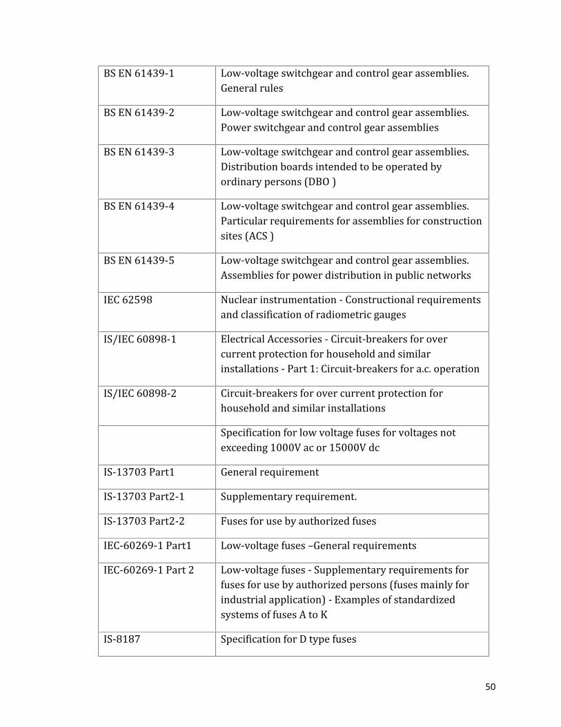
The control cabinets, junction boxes and marshalling boxes shall comply in allrespects with the following codes of the Bureau of Indian Standards (BIS),International Electrotechnical Commission (IEC) and British Standards (BS):IS/IEC 60947-1 Part 1 Low-Voltage Switchgear And Control gear - GeneralRulesIS/IEC 60947-1 Part 2 Low-Voltage Switchgear And Control gear - CircuitbreakerBS EN-60947 Part2 Low-Voltage Switchgear And Control gear - CircuitbreakerBS EN-60947 Part3 Switches disconnectors switch - disconnectors andfuse-combination unitsBS EN-60947 Part4-1 Contactors and motor-starters. Electromechanicalcontactors and motor-startersIS 8623 Part1 Specification for low voltage switchgear and controlgear assemblies - Requirement for type tested andpartially type tested assembliesIS 8623 Part2 Particular requirements for bus bar trunking systems(bus ways )
50
BS EN 61439-1 Low-voltage switchgear and control gear assemblies.General rulesBS EN 61439-2 Low-voltage switchgear and control gear assemblies.Power switchgear and control gear assembliesBS EN 61439-3 Low-voltage switchgear and control gear assemblies.Distribution boards intended to be operated byordinary persons (DBO )BS EN 61439-4 Low-voltage switchgear and control gear assemblies.Particular requirements for assemblies for constructionsites (ACS )BS EN 61439-5 Low-voltage switchgear and control gear assemblies.Assemblies for power distribution in public networksIEC 62598 Nuclear instrumentation - Constructional requirementsand classification of radiometric gaugesIS/IEC 60898-1 Electrical Accessories - Circuit-breakers for overcurrent protection for household and similarinstallations - Part 1: Circuit-breakers for a.c. operationIS/IEC 60898-2 Circuit-breakers for over current protection forhousehold and similar installationsSpecification for low voltage fuses for voltages notexceeding 1000V ac or 15000V dcIS-13703 Part1 General requirementIS-13703 Part2-1 Supplementary requirement.IS-13703 Part2-2 Fuses for use by authorized fusesIEC-60269-1 Part1 Low-voltage fuses –General requirementsIEC-60269-1 Part 2 Low-voltage fuses - Supplementary requirements forfuses for use by authorized persons (fuses mainly forindustrial application) - Examples of standardizedsystems of fuses A to KIS-8187 Specification for D type fuses

51
BS-775 Part1 Multichannel stereophonic sound system with andwithout accompanying pictureBS-775 Part 2 Multichannel stereophonic sound system with andwithout accompanying pictureBS-775 Part3 Multichannel stereophonic sound system with andwithout accompanying pictureIEC-947-4-1 Part1 Low-voltage switchgear and control gear - Part 4-1:Contactors and motor-starters - Electromechanicalcontactors and motor-startersIEC-947-4-2 Part 2 Low-voltage switchgear and control gear - Part 4-2:Contactors and motor-starters - AC semiconductormotor controllers and startersIS-3231 Part1.1 Specification for electrical relays for power systemprotectionIS-3231 Part1. 2 Insulation testsIS-3231 Part2 Requirements for principal familiesIS-3231 Part3 Requirements for particular group of relaysIEC-60255 Part1-Part27 Measuring relays and protection equipmentIS-1248 Part1- Part9 Direct acting indicating analogue electrical measuringinstruments and their accessoriesIEC-60051 Direct acting indicating analogue electrical measuringinstruments and their accessoriesIS-5578 Guide for making insulated conductorsIS-11353 Guide for uniform system of marking and identificationof conductors and apparatus terminalsBS-159 Specification for high-voltage bus bars and bus barconnectionsIS-722 AC Electricity Meters

52
BS-5685 Electricity meters. Specification for Class 0.5 1 and 2single-phase and poly phase single rate and multi-ratewatt-hour meters (Obsolescent but remains current )IS-10118 Code of Practice for selection installation andmaintenance of Switchgear and Control gearIS-6005 Code and practice for phosphate coatings of iron andsteelBS 3189 Phosphate conversion coatings for metalsIS-5082 Wrought aluminium and aluminium alloy bars rodstubes sections plates and sheets for electricalapplicationsIEC-60114 Recommendation for heat-treated aluminium alloy busbar material of the aluminium-magnesium-silicon type8.3.6 Bushings, hollow column insulators, support insulators: Bushings shall bemanufactured and tested in accordance with IS: 2099 and IEC:60137.Hollow column insulators shall be in accordance with IEC-60233 / IS: 5621 andsupport insulators as per IS: 2544 / IEC-60168, IEC-60273 and IEC-60815 asapplicable. Composite silicon insulators, conforming to IEC-61109 may also beused.
All iron parts of insulators and bushings shall be hot dip galvanized and all jointsshall be air tight. Surface of joints shall be trued up porcelain parts by grinding andmetal parts by machining. Insulator / bushing design shall be such as to ensure auniform compressive pressure on the joints.8.4 Sub System8.4.1 Substation automation system (SAS): The Substation Automation System (SAS) shallbe installed to control and monitor all the substation equipment from RemoteControl Centre (RCC) as well as from Local Control Centre (LCC).(i) The SAS shall contain the following main functional parts:(a) Bay control Intelligent Electronic Devices (IED s) for control and monitoring;(b) Station Human Machine Interface (HMI);
53
(c) Redundant managed switched Ethernet;(d) Local Area Network communication infrastructure with hot standby;(e) Peripheral equipment like printers, display units, key boards, Mouse etc.(ii) The SAS shall enable local station control via PC by means of HMI andcontrol software package, which shall contain an extensive range of SCADAfunctions.(iii) The SAS shall include communication gateway, intelligent electronicdevices (IEDs) for bay control and inter IED communication infrastructure.The communication gateway shall facilitate the information flow withremote control centers. The bay level intelligent electronic devices(IEDs) for protection and control shall provide the direct connection tothe switchgear without the need of interposing components/wiring andperform control, protection, and monitoring functions.8.4.2 Power line communication and protection of transmission system: The power linetele-communication and protection equipment shall be provided at both ends ofall the Transmission Lines.(a) Communication(i) Frequency Planning: For planning frequency and output power of carrierterminals, the minimum signal to noise ratio of 25 dB for the speechchannels without companders shall be adopted.(ii) Proposed Arrangement: The power line tele-communication and tele-protection equipment shall provide secure and reliable information link forspeech communication, data transfer, distance protection and direct trippingof remote-end breakers.(b) Protection(i) Protective Relaying System: Adequately sectionalized and graded protectiverelaying system shall be provided for transmission lines, transformers andbus bars so as to automatically isolate the faulty equipment. All mainprotection relays shall be of numerical type and communication protocolshall conform to IEC-61850.( i i ) Grouping of Protection: The protection functions shall be subdivided intotwo groups each being independent and capable of providing uninterrupted

54
protection even in the event of one of the protection groups failing.Grouping shall be done to the extent possible in such a way that eachgroup can independently carry out protective functions with near equalredundancy. Interconnection between these two groups shall notgenerally be attempted.(iii) Guidelines: The protection in respect of Transmission Lines, PowerTransformers, Circuit Breakers, Bus-bars and other provisions shall be asper CEA (Technical Standards for Construction of Electrical Plants andElectric Lines) Regulation 2010 and CBI&P guidelines on Protection.(iv) Bus bar Protection and Local Breaker Backup Protection: Duplicate Bus barprotection for 400 kV, single bus-bar protection for 220 kV systems and localbreaker backup protection for 400 kV and 220 kV shall be provided. The busbar protection scheme shall have provision for future expansion and spaceplanning for the same shall be done at project planning stage itself.(v) Disturbance Recorders, Event Loggers and Time Synchronization Equipment:Each line shall be provided with facility for disturbance recording, distanceto fault locator and Time Synchronizing Equipment (TSE). TSE completewith antenna, all cables, processing equipment etc., shall be provided toreceive synchronizing pulse through GPS compatible for synchronizationof event logger, disturbance recorder and SCADA/automation system of thesub- station or switchyard.The Power Line Tele-Communication and Tele-Protection Equipment shall complywith the following codes of Bureau of Indian Standards (BIS):IS 9859 Part1 Code and practice for installation and maintenance of outdoorpower line carrier equipment -Line trapIS 9859 Part2 Code and practice for installation and maintenance of outdoorpower line carrier equipment -Coupling devicesIS 9859 Part3 Code and practice for installation and maintenance of outdoorpower line carrier equipment -Coupling capacitor/capacitorvoltage transformer8.4.3 Inter utility metering system: The Energy Metering System as specified in CEA(Installation and Operation of Meters) Regulations, 2006 dealing with installation

55
and operation of meters including interface meters shall be used for tariff meteringfor bulk inter- utility power flows in the Grid system. The metering system shall beinstalled on each circuit as a self contained device for recording andmeasurement of active energy and reactive energy in each successive 15-minuteblock including other functions as described in the CEA’s Notification referredabove.8.5 Substation and switchyard support facilities8.5.1 Illumination and Lighting: The Concessionaire shall design, provide and maintain atall times a good indoor and outdoor lighting and illumination system in asubstation both for normal and emergency situations to ensure safety of theworking personnel.The illumination levels and lighting systems shall comply with the following codes ofthe Bureau of Indian Standards (BIS) and CBI&P:IS 3646 Part 1and 2 Principles of good lighting and aspects of designs, code of practice
IS 3646 Part 3 Code of practice for interior illumination.CBI&P CBI&P Manual on Substation Layout Publication No. 2998.5.2 Earthing System: The earthing system shall be designed to protect equipments andhuman life against excessive touch voltages in fault conditions and to keeptransferred potential to minimum.As per IEEE 80, the acceptable value of effective resistance of earthing gridconsidered is less than 1 Ω. The parameters associated with ground gradients viz.,GPR, touch and step potentials shall be within acceptable limits.The earthing systems shall comply in all respects with the following codes of theBureau of Indian Standards (BIS), Institute of Electrical and Electronics Engineers(IEEE) and CBI&P:IEEE 80-2000 Guide for Safety for AC Substation GroundingCBIP CBIP Manual on earthing of AC Power Systems, Publication no.302IS 3043 Indian standard for code of practice for earthing

56
8.5.3 Fire Protection System: The fire detection, alarm and protection system forsubstation and switchyard shall be provided as per CEA (Construction of ElectricalPlants and Electric Lines) Regulations 2010.8.5.4 Air Conditioning System: Air Conditioning (AC) requirement shall be met usingindividual split AC units. AC units for control room building shall maintain DBT24.400 C +/- 20 C. The following facilities shall be air conditioned:(a) Control room;(b) Engineer’s room;(c) Battery room;(d) Electronics test lab; and(e) Conference Room.8.5.5 Oil evacuation, filtering, testing and filling apparatus: To monitor the quality of oilfor satisfactory performance of transformers, shunt reactors and other oil filledequipments, and for periodical maintenance, necessary oil evacuation, filtering,testing and filling apparatus shall be provided at the substation. Oil tanks ofadequate capacities for storage of pure and impure transformer oil shall also beprovided.8.5.6 SF6 filling, evacuation, filtering, drying and recycling plant: SF6 filling, evacuation,filtering, drying and recycling plant with adequate storage capacity shall beprovided at the substation along with trolley for filling or evacuation of SF6 gascircuit breaker and to monitor the purity, moisture content, decomposition productetc. of SF6 gas.8.6 Mandatory initial spares, tools and tackles
M andatory spares shall be kept in stores as per the CERC / SERC guidelines andgood Industry Practice. The inventory of spare parts shall at all times be maintainedby replenishing in case any item is utilized during construction and commissioningor operation and maintenance.
57
SECTION 9
GAS INSULATED SUBSTATION (GIS)
9.1 General9.1.1 Gas insulated substation comprising of operating devices, accessories andauxiliary equipment shall be metal-enclosed SF6 gas type as per IEC 62271-203. The GIS shall be indoor/ outdoor type.9.1.2 400kV GIS system, shall be single phase type. 220/132kV GIS system shall be threephase or single phase or a mixture of both. 33kV GIS shall be three phase type.9.1.3 The arrangement of gas sections/compartments shall be such as to facilitatefuture extension of any make on either end without drilling, cutting or welding onthe existing GIS. It shall not be necessary to move or dislocate the existingsubstation bays for adding the equipment. GIS shall be totally safe againstinadvertent touch of any of its live parts. It shall be protected against all types ofvoltage surges.9.1.4 GIS shall include all the necessary equipment/accessories for satisfactory operationand erection of the GIS substation. The ladders and walkways shall be providedwherever necessary for access to the equipment.9.2 Constructional requirements
9.2.1 The material a n d thickness of the enclosures shall withstand the internal flashover without burn through a t rated fault current for a period as per IEC 62271-203.9.2.2 Each pressure filled enclosure shall be designed and fabricated to comply with therequirements of the applicable codes and pressure vessel shall be based on thedesign temperature and pressures as per relevant IEC. The maximum gas leakagefor GIS shall not be more than 0.5% of iterated pressure per year.9.2.3 The fabricated metal enclosures shall be of non-magnetic material with highresistance to corrosion, low electrical losses and negligible magnetic losses.

58
9.2.4 The disconnecting switches and earth switches shall preferably be providedwith windows to inspect switch contact positions directly.9.2.5 Enclosures shall be single phase/three phase (as applicable) encapsulationfor bus bars and feeder section bays. The substation shall be modular in designwith provision of future extensions.9.3 Major equipments
9.3.1 Circuit Breaker: Circuit breaker (CB) shall be of SF6 gas insulated single phase/three phase (as applicable) type. It shall be self blast /puffer type and consist of oneinterrupting chamber upto 245kV, two interrupting chambers upto 400kV andmaximum four interrupting chamber upto 765kVThe arrangement shall be horizontal/vertical as per manufacturer preferredlayout considering space limitation and taking into account the worst serviceconditions/forces imposed by earth quake. The breaker enclosure shall haveprovision for easy withdrawal of the interrupter assemblies. The removedinterrupter assembly must be easily and safely accessible for inspection andpossible repairs.Refer Part B, Section 8, Clause 8.2.2 of the manual for details and standards.
9.3.2 Disconnectors (isolators) and earth switches: Disconnectors shall be single pole,group control with motor operated mechanism as per IEC 62271-102. Theprovision of emergency manual operation shall also be included.Earth switch shall be provided with manual operating mechanism as per IEC-62271-102. M otor operated mechanism shall be provided with electrical controlfrom local position. Safety interlocks shall be provided for closing of earthswitch when disconnector is open and vice versa.The following points shall be noted in case of fast acting earthing switches:(i) Fast acting earthing switches as per IEC 62271-102, located on the lineside of feeder bay module shall be of three-pole, group operated, highspeed make- proof type to discharge the charging currents in addition to
59
their safety grounding function. It shall interrupt inductive currents andwithstand transient recovery voltage (TRV) also.(ii) The Short Circuit Making Current of earth switch shall be at least equalto its peak withstand current rating. The switches shall haveelectrostatic and electromagnetic induced current switching capabilityalso.(iii) Earthing switch shall be provided with clearly identifiable local positivedriven mechanical indicator and position indicator on the bay modulecontrol cabinet and provision for remote signaling.(iv) Earthing switch operation shall be possible by local control cabinet orremote control room in addition to opening of the associateddisconnector.Refer Part B, Section 8, Clause 8.2.3 of the manual for details and standards.
9.3.3 Current Transformer: Current transformer (CT) and its accessories forprotection and metering as per IEC 60044-1 shall be incorporated into the GISand shall be of metal enclosed type. The secondary windings shall be air-insulated and mounted inside separate metal enclosure. CT shall be provided witheffective electromagnetic shields to protect against high frequency transientstypically 1-30MHz. CT burden shall not be less than 10VA to achieve required0.2S accuracy class.Refer Part B, Section 8, Clause 8.2.4 of the manual for details and standards.
9.3.4 Voltage Transformer: Voltage transformers (VT) shall be of the electromagnetictype with SF6 gas insulation as per IEC 60044-2. VT shall be located in a separatemodule and will be connected phase t o ground. Effective shielding against highfrequency electromagnetic transients shall be provided. The VT burden formetering class winding shall not be less than 50VA to achieve 0.2S accuracyclass.Refer Part B, Section 8, Clause 8.2.5 of the manual for details and standards.
9.3.5 Outdoor Bushings: Porcelain bushings shall conform to IEC 60137. SF6 to airbushing shall be of ceramic insulator and pressurized with SF6 gas. The conductor

60
shall be supported by the insulator cone at the switchgear end and the high-voltage electrode at the air end.9.3.6 Surge Arrestors: Surge arrestors (SA) with counter shall be outdoor airinsulated/SF6 gas insulated metal oxide and gapless type as per IEC 60099-4.The metal housing of SF6 gas insulated SA shall be connected to the metalenclosure of the GIS with a flanged, bolted and gasket joint so that thearrester housing is grounded through the GIS enclosure. The ground connectionshall be sized for GIS fault level.The detailed system studies and calculations including insulation co-ordinationshall be carried out before evolving the required parameters, locations, energycapabilities etc. of SA.Refer Part B, Section 8, Clause 8.2.6 of the manual for details and standards.9.4 Sub-Systems
9.4.1 Gas insulated Bus duct: The components of GIS including transformers shall beconnected by SF6 insulated bus consisting of an inner conductor and outerenclosure.9.4.2 HV Power cable connection: The cable end box shall be as per relevant lEC.The final connection of the high voltage cable circuits in GIS shall be with single-phase cables. All cable end modules shal l be suitable for connecting singlecore, XLPE solid dielectric cable or low pressure o i l filled cable type.
Transformer shall be connected to GIS outgoing bus duct using completeenclosed adapters. The transformer bushing housing shall be as per IEC61639. The adapter shall have a removable bus link to a l l o w electricallydisconnecting the transformer from the bus, for testing of the bus/transformer separately and removal of the transformer, if required.9.4.3 Gas system:(i) GIS shall be provided with adequate SF6 gas to pressurize the completesystem. One zone/ compartment shall be pressurized to the rated nominalgas density.(ii) The rated pressure of SF6 gas in GIS equipment shall be as low aspossible, while still meeting the requirements for electrical

61
insulation and space limitations to reduce the effects of leaks and toensure that there is no chance of the gas liquefying at the lowestambient temperature.(iii) SF6 gas shall be as per IEC 60376. Certificate of poison inspection shallbe provided with supplied gas.(iv) Self sealing vacuum couplings shall be provided on all gas compartmentsto facilitate filling and recharging.(v) Gas filling and evacuating plant shall be provided necessary forfilling-in/evacuating SF6 gas from GIS. This shall include all thenecessary gas cylinders for temporarily storing the evacuated SF6gas. The capacity of temporary .storage facilities shall be sufficientfor storing the maximum quantity of gas that may be evacuatedduring maintenance/repair work of atleast one complete bay of GIS.9.4.4 Local control cubicle: Local control cubicles shall be provided for control andinterlocking, local operation of various equipments and indicating and measuringequipment for each bay/module.9.4.5 GIS earthing:(i) GIS shall be provided with provisions consisting of grounding pads to connectwith the ground mat riser near the equipment.(ii) The earthing system shall be based on multi-point design ensuring theprotection in case of indirect contact (touch or step voltages, in case of fault)- and transient phenomena in case of lightning or switching operations.(iii) The three enclosures of single phase GIS shall be bonded at the ends of GIS toneutralize the flow of circulating currents. All wirings to GIS shall be shieldedand grounded.(iv) The enclosure of GIS shall be adequately grounded to limit the potentialdifference between individual sections within allowable limit of 65-130Vduring faults.(v) Earthing conductors shall withstand rated short circuit current. Conductorswith copper bars shall be preferred over copper wires. Separate ground stripsto short circuit flanges and earthing switches shall not be provided.9.4.6 GIS Foundation Grounding:. A simple monolithic concrete steel reinforced slab

62
shall be provided to serve both as auxiliary grounding device and for seismicreasons. Concrete foundations may cause irregularities in current dischargepath in gas insulated substations.9.4.7 Monitoring system:(i) Dew point meter: Portable Dew point meter for measuring the dew point ofSF6 gas of CB/GIS shall be provided and adequately protected for outdoor use.The meter shall be provided with dew point hygrometer with digital indicationto display the dew point temperature in Celsius or Fahrenheit or PPM. Itshall be capable of measuring the corresponding pressure at which dewpoint is being measured.(ii) Partial discharge monitoring system: The equipment shall be used for detectingdifferent type of defects in GIS viz particles, loose shields and partialdischarges. The instrument shall also be able to detect partial discharges incable joints, terminations, CT and PT etc.9.5 International/ Indian StandardsThe GIS shall comply in all respects to the following codes of the Bureau of IndianStandards (BIS), International Electrotechnical Commission (IEC),British Standard(BS), Institute of Electrical and Electronics Engineers (IEEE) and EuropeanStandards (EN):
STANDARDREFERENCE
TITLEIEC-60050 International electro-technical vocabularyIEC-62271-203 High voltage alternating current circuit breakersIEC-62271-203 Gas-insulated metal-enclosed switchgear for rated voltages 52 kVand aboveIEC-60060 High voltage test techniquesIEC-60114 Recommendation for heat treated aluminium alloy bus bar materialof the aluminium-magnesium-silicon typeIEC-62271-102 Alternating current disconnect switches and grounding switches

63
IEC-60137 Bushing for alternating voltages above 1000 voltsIEC-60044-1 Instrument transformers part 1: current transformersIEC-60044-6 Requirements for protective current transformers for transientperformanceIEC-60044-2 Instrument transformers part 2: inductive voltage transformersIEC-60255 Electrical relaysIEC-60269 Low voltage fusesIEC-60292 Low voltage motor startersIEC-60376 Specification and acceptance of new sulphur hexafloride.IEC-60376 Aand B First and second supplement to IEC pub-376 (1971 )IEC-60427 Synthetic testing of high voltage alternating current circuit breakersIEC-60480 Guide for checking sf-6 gas taken from electrical equipmentIEC-60507 Artificial pollution test on hv insulators to be used on ac systemIEC 61639 Direct connections between Power Transformers and gas insulatedmetal-enclosed switchgear for rated voltages 72.5kv and aboveIEC-60529 Classification of degree of protection provided by enclosuresIEC-60694 Common clauses for hv switchgear and control gear standardsIEC-60932 Additional requirement for enclosed switchgear and control gearfrom 1 kv to 72.5 kv for use in severe climate conditionsIEC-60815 Guide for selection of insulators in respect of polluted conditionsIEC-61259 Gas insulated metal – enclosed switchgear for rated voltages 72.5 kvand above – requirements for switching of bus charging circuit bydisconnect switchesBS-5045-1 Specification for transportable gas containers. Seamless steelcontainers.IEEE STD. 80 Ieee guide for safety in ac substation grounding

64
ANSI/IEEEC37.122 Standard for gas insulated substationsISO-9003 Quality systems – model for quality assurance in final inspection andtestEN-50052 European standard – cast aluminium alloy enclosures for gas filledhigh voltage switchgear and control gearEN-50064 Wrought aluminium and aluminium alloy enclosure for gas filledhigh voltage switchgear and control gearEN-50069 Welded composite enclosures of cast and wrought aluminium alloysfor gas filled high voltage switchgear and control gearIEC-60859 Cable connection for GISANSI/IEEE1291 Guide for partial discharge measurements in power switchgearIEC-60099-5 Surge arresters-part 5: selection and application recommendationsIEC-60099-4 Surge arresters-part 4: metal-oxide surge arresters without gaps forac systems
65
SECTION 10
CIVIL WORKS
10.1 GeneralAll structures, buildings, foundations, layout and other details shall be designed anddeveloped keeping in view the functional requirement of the transmission line andsubstation and shall conform to the National Building code, relevant codes of IRCand Good Industry Practice:10.2 Roads, culverts, PCC Pavement and ParkingAll internal roads, culverts, PCC pavements and parking within the substation areaand approach road from the main road to the substation shall be constructed as perRajasthan PWD specifications and as per layout in the GELO / CLO of thesubstations.10.3 Fire Protection WallsFire protection walls in order to protect against the effects of radiant heat and flyingdebris from an adjacent fire shall be designed and provided in accordance withTariff Advisory Committee (TAC) stipulations. The partitions meant to reduce thenoise level of the transformers, shall have the same fire resistance if the partitionsare also used as fire walls. A minimum of 2 meters clearance shall be providedbetween the equipments and fire walls. The building walls which act as fire wallsshall extend at least 1 m above the roof in order to protect it. These walls should be1-2 hr. fire rated construction.10.4 Cable and Pipe TrenchesThe layout and size of cable and pipe trenches shall be detailed in the GELO. Thetop of trenches shall be kept at least 25 mm above the gravel level so that rainwater does not enter the trench.(i) Outdoor Cable Trenches: RCC cable trenches shall be constructed in theswitchyard and fibre glass/pre-cast RCC removable covers with lifting arrangement,edge protected with suitable galvanized angle iron designed to withstand selfweight of top slab in addition to concentrated load of 150 kg at center of span on

66
each panel.(ii) Indoor Cable Trenches: RCC indoor cable trenches shall be provided with 50X50X6mm GI angles grouted on the top edge of the trench wall for holding minimum 7 mmthick mild steel checkered plate covers with lifting arrangement. ISMC GI channelsof 75x40 mm shall also be grouted at distances of 600 mm across the indoor cabletrenches to support the checkered plates. The width of trench wall should beminimum 200mm(iii) Trench Drainage: The trench bed shall have a slope of 1/500 along the runand 1/200 perpendicular to the run. In case straight length exceeds 30 m, suitableexpansion joint shall be provided at appropriate distances. The expansion joint shallrun through vertical wall and base of trench. All expansion joints shall be providedwith approved quality PVC water stops of approx. 230x5 mm size. Man holes shallbe provided at interval of not more than 30 meters(iv) Trench - Road CrossingsSuitable box culvert (Single span or multi spans) shall be provided for any roadcrossing. The box culvert shall extend 1.5 m on each side of road and shall have 230-mm wide, 500 mm high brick parapet wall at ends. If required, the bed of trench onboth sides of culvert shall have to be lowered in slope, in 1.5 m length to meet thebed of culvert.10.5 Foundations For RCC Construction WorksAll the foundations except walls of switch house cum administrative and firehydrant building shall be of Reinforced Cement Concrete. All properties of concreteregarding its strength under compression, tension, shear, punching and bondstrength etc. as well as workmanship shall conform to IS: 456. Foundation may beof pad or trapezoidal isolated type.10.5.1.Sliding and Overturning Stability: All sub-structures shall be checked for slidingand overturning stability both during construction and operating conditions forvarious combinations of loads. Factor of safety for these cases shall be taken asmentioned in relevant IS Codes or as stipulated elsewhere in the specifications.10.5.2 Depth of Foundations: In case of overlapping of foundations in switchyard area,deeper foundation shall be constructed first. For the foundations resting on filledup soil, the fill material under foundation / trenches shall be such that themaximum pressure from the footing transferred through fill material will not
67
exceed the allowable soil bearing pressure of original undistributed soil. In caseearth filling is involved due to high fixation of formation level, All foundations shallrest below virgin ground level and the minimum depth excluding lean concrete ofall foundations below virgin ground level shall not be less than 500 mm.10.5.3 Height of Foundations: The Switch Yard foundations shall be at least 100 mmabove the finished ground level or as per the manufacturers’ design.10.5.4 Plinth Levels: The plinth level of the Control Room-cum-Administrative buildingshall be minimum 500 mm above the finished ground level.10.6 Buildings10.6.1.Design Criterion: The buildings shall be designed to withstand the earth quakepressure as per the requirements of the National Building Code of India.10.6.2.Design Loads: Building structures shall be designed for the most criticalcombinations of dead loads, superimposed loads, equipment loads, crane loads,wind loads, seismic loads, short circuit loads and temperature loads as indicated inIS456 and IS1893. In addition, loads and forces developed due to differentialsettlement shall also be considered.10.6.3.DG Building Cum Fire Fighting Pump House and RCC Water Storage Tank: The DGand Fire fighting buildings designed to accommodate up to [two (2)] DG sets, motors/ pumps as per fire fighting requirement and a permanent crane, hoist and servicetrucks mounted on suitable steel structure (I-section / RS joist) below the ceiling forservicing, lifting and maintenance of the heavy equipment shall be constructedadjacent to each other for convenience of maintenance of equipment.10.6.4.Painting and Finishing: All paints and allied materials shall be of superior quality,conform to the relevant Indian Standards and of approved brands and shades.10.7 FlooringThe flooring of Control Room-cum-Administrative building except conferenceroom, control room, reception hall and reception stairs shall be made of ordinarypolish Kota of approved quality minimum 25 mm thick in plain or diamond pattern.Entire area around the Control Room-cum-Administrative building, DG-cum-firefighting building, security hut and the driver’s room shall be provided with PCCpaving up to 1 meter from the outer edge of the buildings.
68
10.8 Doors / WindowsAluminium frames / doors / windows / ventilators (single and double leaf)consisting frame work including vertical styles, top rails, lock (middle) rails andbottom rails with metal fastener and screws shall be fitted with nuts and bolts orusing plastic plugs and screws. The Aluminum section to be used shall be ofminimum 3 mm, anodized (15 micron) of reputed makes conforming to relevantstandards. The Aluminium doors and windows shall be fitted with minimum 5.5 mmthick glass of reputed make with high-class rubber gaskets. The door, floor springs,locks, handles, tower bolts, stoppers with rubber cushion, screws etc. shall be of 1stquality bearing ISI quality certification mark.10.9 Switchyard Fencing and GatesFencing and Gates shall be provided for Switchyard area as per General ElectricalLayout Plan. The height of fence post shall be at least 3050 mm.10.10 Boundary and Retaining WallsA Boundary wall shall be constructed all around the entire substation in accordancewith Good Industry Practice.10.11 Indian StandardsCivil Works shall comply in all respects to the following codes of the Bureau of IndianStandards (BIS):
IS 110 Ready mixed paint, brushing, grey filler, for enamels for use overprimers (second revision)IS 269 Ordinary Portland Cement, 33 Grade- Specification (fifth revision)IS 280 Mild steel wire for general engineering purposes (fourth revisionwith amendment no. 1)IS 287 Permissible moisture content of timber used for differentpurposes- Recommendations (third revision)IS 337 Specification for varnish, finishing, interiorIS 348 Specification for French polis (first revision)
69
IS 383 Specification for coarse and fine aggregates from natural sourcesfor concrete (second revision)IS 412 Specification for expanded metal steel sheets for general purposes(second revision)IS 419 Specification for putty, for use on window frames (first revision)IS 428 Washable distemper- SpecificationIS 456 Plain and Reinforced Concrete - Code of Practice (third revisionwith amendment no. 4)IS 702 Specification for industrial bitumen (second revision)IS 710 Marine plywood- Specification (second revision)IS 712 Specification for building limes (third revision with amendment no.1)IS 733 Specification for wrought aluminium and aluminium alloys, bars,rods and sections for general engineering purposes (thirdrevision)IS 777 Specification for glazed earthenware tilesIS 1003(Part 1) Timber panelled and glazed shutters - Specification, Part 1: Doorshutters (fourth revision)IS 1003(Part 2) Timber panelled and glazed shutters - Specification, Part 2:Window and ventilator shutter (third revision)IS 1038 Specification for steel doors, windows and ventilators (thirdrevision with amendment no. 3)IS 1077 Common burnt clay building bricks - Specification (fifth revision)IS 1081 Code of practice for fixing and glazing of metal (steel andaluminium) doors, windows and ventilators (with amendment no.1)IS 1124 Method of test for determination of water absorption, apparentspecific gravity and porosity of natural building stones (firstrevision)

70
IS 1237 Cement concrete flooring tiles- Specification (second revision)IS 1322 Bitumen felts for water-proofing and damp-proofing- Specification(fourth revision)IS 1346 Code of practice for water-proofing of roofs with bitumen felts(third revision)IS 1361 Specification for steel windows for industrial buildings (firstrevision)IS 1397 Kraft paper- Specification (second revision)IS 1443 Code of practice for laying and finishing of cement concreteflooring tiles (first revision)IS 1477(Part 1) Code of practice for painting of ferrous metals in buildings, Part 1:Pretreatment (first revision)IS 1477(Part 2) Code of practice for painting of ferrous metals in buildings, Part 2:Painting (first revision)IS 1542 Sand for plaster - Specification (second revision)IS 1580 Bituminous compounds for water-proofing and caulking purposes-Specification (second revision)IS 1597(Part 1) Construction of stone masonry - Code of practice, Part 1: Rubblestone masonryIS 1659 Block boards - Specification (fourth revision)IS 1661 Code of practice for application of cement and cement-limeplaster finishes (first revision)IS 1834 Specification for hot applied sealing compound for joints inconcrete (first revision)IS 1838 Specification for preformed fillers for expansion joint in concretepavements and structures (non extruding and resilient type), Part1: Bitumen impregnated fibre (first revision with amendment no.1)IS 1893 Criteria for earthquake resistant design of structures (fourth

71
revision with amendment no. 1)IS 1948 Specification for aluminium doors, windows and ventilators (withamendment no. 1)IS 1949 Specification for aluminium windows for industrial buildings (withamendment no. 1)IS 2074 Ready mixed paint, air drying, red oxide-zinc chrome, priming(second revision)IS 2114 Code of practice for laying in-situ terrazzo floor finishIS 2116 Specification for sand for masonry mortarsIS 2185(Part 1) Specification for concrete masonry units, Part 1: Hollow and solidconcrete blocksIS 2185(Part 2) Specification for concrete masonry units, Part 2: Hollow and solidlight weight concrete blocksIS 2185(Part 3) Specification for concrete masonry units, Part 3: Autoclavedcellular aerated concrete blocksIS 2202(Part 1) Wooden flush door shutters(Solid core type) - Specification,Part 1: Plywood face panelsIS 2202(Part 2) Wooden flush door shutters(Solid core type) - Specification,Part 2: Particle board and hardboard face panelsIS 2212 Brick works - Code of practice (first revision)IS 2250 Code of practice for preparation and use of masonry mortars (firstrevision)IS 2338(Part 1) Code of practice for finishing of wood and wood based materials,Part 1: Operations and workmanshipIS 2338(Part 2) Code of practice for finishing of wood and wood based materials,Part 1: SchedulesIS 2339 Aluminium paint for general purposes, in dual container (withamendment no. 1)IS 2395 Code of practice for painting concrete, masonry and plaster

72
(Part 1) surfaces, Part 1: Operations and workmanshipIS 2395(Part 2) Code of practice for painting concrete, masonry and plastersurfaces, Part 1: SchedulesIS 2402 Code of practice for external rendered finishesIS 2571 Code of practice for laying in-situ cement concrete flooring (firstrevision)IS 2572 Code of practice for construction of hollow concrete blockmasonry (first revision)IS 2645 Specification of integral cement waterproofing compoundsIS 2690(Part 1) Burnt clay flat terracing tiles - Specification, Part 1: Machinemade (second revision)IS 2691 Specification for burnt clay facing bricks (second revision)IS 2750 Specification for steel scaffoldings (with amendment no. 1&2)IS 2835 Flat transparent sheet glass (third revision)IS 2932 Specification for enamel, synthetic, exterior: (a) Undercoating, (b)finishingIS 3036 Laying lime concrete for a waterproofed roof finish - Code ofpractice (second revision)IS 3067 Code of practice of general design details and preparatory work fordamp-proofing and water-proofing of buildings (first revision)IS 3068 Specification for broken brick (burnt clay) coarse aggregates foruse in lime concrete (second revision)IS 3384 Specification for bitumen primer for use in waterproofing anddamp-proofing (first revision)IS 3461 Specification for PVC asbestos floor tilesIS 3462 Specification for unbacked flexible PVC flooring (second revision)IS 3495(Part1) Methods of tests for burnt clay building bricks, Part 1:Determination of compressive strength (third revision)
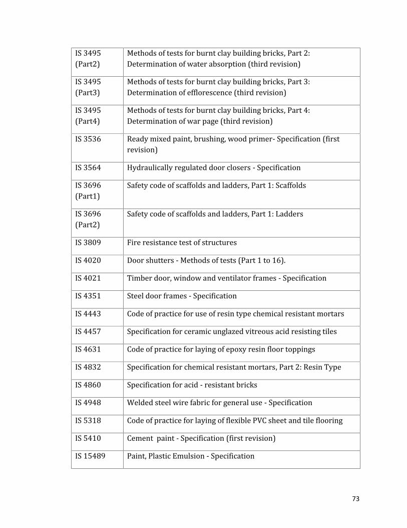
73
IS 3495(Part2) Methods of tests for burnt clay building bricks, Part 2:Determination of water absorption (third revision)IS 3495(Part3) Methods of tests for burnt clay building bricks, Part 3:Determination of efflorescence (third revision)IS 3495(Part4) Methods of tests for burnt clay building bricks, Part 4:Determination of war page (third revision)IS 3536 Ready mixed paint, brushing, wood primer- Specification (firstrevision)IS 3564 Hydraulically regulated door closers - SpecificationIS 3696(Part1) Safety code of scaffolds and ladders, Part 1: ScaffoldsIS 3696(Part2) Safety code of scaffolds and ladders, Part 1: LaddersIS 3809 Fire resistance test of structuresIS 4020 Door shutters - Methods of tests (Part 1 to 16).IS 4021 Timber door, window and ventilator frames - SpecificationIS 4351 Steel door frames - SpecificationIS 4443 Code of practice for use of resin type chemical resistant mortarsIS 4457 Specification for ceramic unglazed vitreous acid resisting tilesIS 4631 Code of practice for laying of epoxy resin floor toppingsIS 4832 Specification for chemical resistant mortars, Part 2: Resin TypeIS 4860 Specification for acid - resistant bricksIS 4948 Welded steel wire fabric for general use - SpecificationIS 5318 Code of practice for laying of flexible PVC sheet and tile flooringIS 5410 Cement paint - Specification (first revision)IS 15489 Paint, Plastic Emulsion - Specification

74
IS 5437 Wired and figured glass - SpecificationIS 5491 Code of practice for laying for in situ granolithic concrete floortoppingIS 6041 Code of practice for construction of autoclaved cellular concreteblock masonryIS 6042 Code of practice for construction of light-weight concrete blockmasonryIS 6248 Specification for metal rolling shutters and rolling grills (firstrevision)IS 7193 Glass fibre base bitumen felts - Specification (second revision)IS 7452 Hot rolled steel sections for doors, windows and ventilators -SpecificationIS 8042 White Portland Cement - Specification (second revision)IS 8543(Part 1/Sec1) Methods of testing plastics Part 1 Characterization of polymerstructure and size, Section 1 Determination of molecular mass fromviscosityIS 8543(Part 13/Sec1) Methods of Testing Plastics: Part 13 Test for Specific Products - Sec1 : Buttons (Thermosetting)IS 13360(Part 2/Sec1) Plastics - Methods of test Part 2 Sampling and preparation of testspecimens Sec 1 Compression moulding test specimens ofthermoplastics materialsIS 13360(Part 2/Sec2) Plastics - Methods of Testing - Part 2 : Sampling and Preparation ofTest Specimens - Section 2 : Compression Moulding of TestSpecimens of Thermosetting MaterialsIS 13360(Part 2/Sec3) Plastics - Methods of Testing - Part 2 : Sampling and Preparation ofTest Specimens - Section 3 : Injection Moulding of Test Specimensof Thermoplastic Materials - General PrinciplesIS 13360(Part 3/Sec Plastics - Methods of Testing - Part 3 : Physical and DimensionalProperties - Section 1 : Determination of Density and Relative

75
1) Density of Non-Cellular PlasticsIS 13360(Part 5/Sec2) Plastics - Methods of Testing Part 5 : Mechanical Properties Sec 2Determination of Tensile Properties - Test Conditions for Mouldingand Extrusion PlasticsIS 13360(Part 5/Sec3) Plastics - Methods of testing : Part 5 Mechanical Properties ,Section 3 Determination of tensile properties - Test conditions forfilms and sheetsIS 9197 Specification for epoxy resin, hardeners and epoxy resincompositions for floor toppingIS 9862 Specification for ready mixed paint, brushing, bituminous, black,lead-free, acid, alkali, water and chlorine resisting---------------