presentation on vsc-based hvdc power transmission systems
DESCRIPTION
presentation on VSC-Based HVDC Power Transmission SystemsTRANSCRIPT
VSC-BASED HVDC POWER TRANSMISSION SYSTEMS
By
PRAMODH H. K.

CAMPARISON OF AC AND DC
ADVANTAGES
Bulk Power Transmission Asynchronous Interconnection of AC Networks Economy of Power Transmission Ability to enhance Transient and Dynamic stability Fast control to limit fault currents
DISADVANTAGES
High cost of DC breakers High cost of conversion equipment Requires AC and DC filters , adding to overall cost Complexity of control

Increasing Progress of high voltage high power semiconductors
Voltage Source converter (VSC) uses Pulse width modulation technique
Operating frequency is determined by switching losses and heat sink
Approximately 100 HVDC installations transmitting 80 GW employing CSC-HVDC and VSC –HVDC
Integration of large scale renewable energy sources with grid
INTRODUCTION

CURRENT SOURCE CONVERTER (CSC)
VOLTAGE SOURCE CONVERTER(VSC)

CSC- HVDC CONFIGURATIONS
Back-to-back CSC-HVDC system with 12-pulseconverters
Monopolar CSC-HVDC system with 12 pulse converters.

Bipolar CSC-HVDC system with one12pulse converter per pole.
Multiterminal CSC-HVDC system parallel connected

VSC HVDC FUNDAMENTAL CONCEPTS
Conventional three-phase two-level VSC topology.
Two-level sinusoidal PWM method : reference(sinusoidal)and carrier signals and line to neutral voltages

Interconnection of two Ac voltage sources through a lossless reactor.
Phasor diagram of two ac voltage sources
interconnected through a lossless reactor.
Active and reactive locus diagram of VSC-based power transmission system.

ADVANTAGES OF VSC OVER CSC
Avoidance of commutation failures due to disturbances in AC network
Independent control of reactive and active power consumed or generated by converter
Possibility to connect VSC HVDC to weak ac network
Faster dynamic response due to higher PWM than the phase controlled operation
No need of transformers to assist the commutation
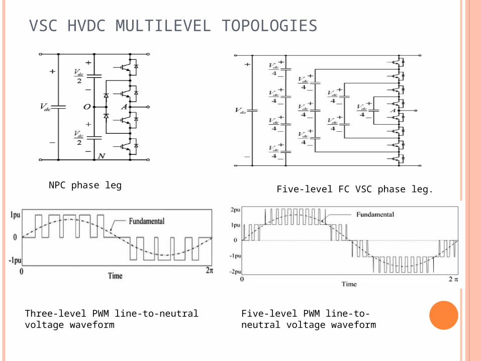
VSC HVDC MULTILEVEL TOPOLOGIES
NPC phase leg Five-level FC VSC phase leg.
Three-level PWM line-to-neutral voltage waveform
Five-level PWM line-to-neutral voltage waveform

Module-multilevel converter topology.(a)Structure of the sub module(SM).(b)Phase leg
ANPC phase leg.

HVDC CIRCUIT BREAKERS
o A configuration employing a conventional ac CB and
a)charged capacitor in parallel with breaker b)resonance circuit in parallel with breaker
o A Solid state CB that consists of a)controllable device such as IGBT ,GTO with
anti parallel diode b) a bidirectional switch that consists of
controllable deviceso A hybrid dc CB where a solid state circuit
breaker, uni-directional or bidirectional configuration is connected in parallel with a conventional ac CB

EMERGING APPLICATIONS
Five-terminal VSC-HVDC system
Single-line multi terminal VSC-HVDC system

Four-terminal PWM VSC-based HVDC system for wind turbine/wind parks
Single-line diagram of wind farm integration using VSC transmissionbased on the three-level NPC converter

CONCLUSIONS
Recent advances of the VSC-based HVDC technology are presented.
four-quadrant static converter interlinking two ac systems through HVDC with a
number of key benefits possibility to connect ac island with no
synchronous generation in the grid VSC-based HVDC technology have
delivered systems at voltage levels up to 350 kV and power levels up to 400 MW

THANK YOU