power systems fundamentals · positive sequence vector rotation ... –zero sequence impedance...
TRANSCRIPT

Symmetrical
Components
David Castor, P.E.

SYMMETRICAL COMPONENTS
AND EASYPOWER
– AN INTRODUCTION
David Castor, P.E.

Why We Use them?
• Using standard single-line diagrams, complex impedances, and phasors, we can analyze steady-state conditions for all sorts of ac systems and configurations – as long as the three phase voltages and currents are equal in magnitude.
• For imbalanced conditions (ground faults) things get extremely complicated to analyze due to the coupling between the three phases.

Symmetrical Components
• C. L. (Charles Legeyt) Fortescue (1918): Any
set of N unbalanced phasors can be
represented by N sets of balanced phasors.– Balanced system can be simulated with single phase. Easier to analyze and
compute.
– Three phase unbalanced vectors three balanced “sequence vectors.”
We still use this mathematical technique to this
day!

Three Sets of “Sequence” Vectors
(Phasors)• Each set of sequence vectors is balanced – that is
what makes this approach easier to solve
• Positive Sequence (e.g. VA1) – this is the normal power system phase sequence quantities
• Negative Sequence (e.g. VA2) – Balanced phasorswith negative phase sequence
• Zero Sequence (e.g. VA0) – Three identical phasors– same phase angle.

Sequence Vectors
o120
o120A1I
B1I
C1I
o120
o120
A2I
B2I
C2I
AoIBoI
CoI
Position of View
Position of View
Position of View
Positive SequenceVector Rotation Direction
Negative SequenceVector Rotation Direction
Zero SequenceVector Rotation Direction

Symmetrical Components
Written in terms of sequence vectors (which are all symmetrical):
𝐼𝐴 = 𝐼𝐴0 + 𝐼𝐴1 + 𝐼𝐴2
𝐼𝐵 = 𝐼𝐵0 + 𝐼𝐵1 + 𝐼𝐵2
𝐼𝐶 = 𝐼𝐶0 + 𝐼𝐶1 + 𝐼𝐶2
AI
BI
CI

Symmetrical Components MathSince sequence vectors are symmetrical and balanced, they have clearly defined relationships:
𝐼𝐵1 = 𝑎2 ∙ 𝐼𝐴1, 𝐼𝐶1 = 𝑎 ∙ 𝐼𝐴1
𝐼𝐵2 = 𝑎2 ∙ 𝐼𝐴2, 𝐼𝐶2 = 𝑎 ∙ 𝐼𝐴2
𝐼𝐴0 = 𝐼𝐵0 = 𝐼𝐶0
Where:
𝒂 = 𝟏∠𝟏𝟐𝟎°

Symmetrical Components Math
𝐼𝐴 = 𝐼𝐴0 + 𝐼𝐴1 + 𝐼𝐴2
𝐼𝐵 = 𝐼𝐴0 + 𝑎2 ∙ 𝐼𝐴1 + 𝑎 ∙ 𝐼𝐴2
𝐼𝐶 = 𝐼𝐴0 + 𝑎 ∙ 𝐼𝐴1 + 𝑎2 ∙ 𝐼𝐴2

Sequence Impedances
Transmission lines:– Pos. & Neg. sequence impedances are equal.
– Zero sequence impedance includes ground wires, shield wires, earth.
Cables, Busway, etc:– Pos. & Neg. sequence impedances are equal.
– Zero sequence similar to transmission line, but can be higher.

Sequence Impedances
Generators:
– Pos. & Neg. similar except for impedances
and voltage induced by rotating machinery.
– Zero sequence varies, but generally smaller
than positive and negative sequence
impedances.
• MV generators normally impedance grounded.

Sequence ImpedancesTransformers:
– Pos. & neg.
sequence
impedances
are equal.
– Zero sequence
depends on
transformer
connections

Fault Calculation Example
BUS-1 12 kV
BUS-2 12 kV
UTIL-1
0.01 + j0.1
0.02 + j0.2
1-9
54
Mag
no
lia
AA
C,
5 m
i.
Look at Line-to-Ground Fault for this simple system

Positive Sequence Network
Util 1R Util 1X Line 1R Line 1X
DriveV

Negative Sequence Network
Util 2R Util 2X Line 2R Line 2X

Zero Sequence Network
Util oR Util oX Line oR Line oX

Combine Networks
• Once the sequence networks are defined, we need to determine how they are interconnected at the fault – this depends on the type of fault
• For a single line-to-ground fault on Phase A, IBand IC equal zero. It can be shown that to satisfy the fault conditions, the three sequence current for Phase A must be equal
• The only way this can happen is for the three sequence networks to be in series.

Resulting Sequence Diagram
• Since the positive and negative sequence impedances are equal, this simplifies to :
Util 1R Util 1X Line 1R Line 1X
DriveV
Util 2R Util 2X Line 2R Line 2X
Util oR Util oX Line oR Line oX
FaultI
DriveFault pu
1 pu o pu
VI =
2Z + Z
Any fault impedance would show up as 3Zf in the sequence diagram since it will be each sequence
ONLY VALID FOR SLG FAULTS!

Other Fault Types• Process is similar for other types of
unbalanced faults
• Sequence networks are the same.
• The difference is in how the sequence networks are interconnected based on the fault conditions.
• Standard references have tables of interconnection of networks for various faults types.
• This is all handled automatically in EasyPower

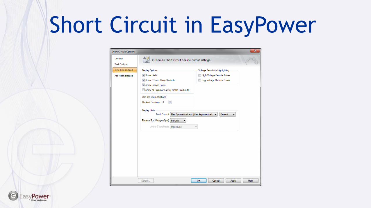
Short Circuit in EasyPower
• One-line display options
Short Circuit in EasyPower
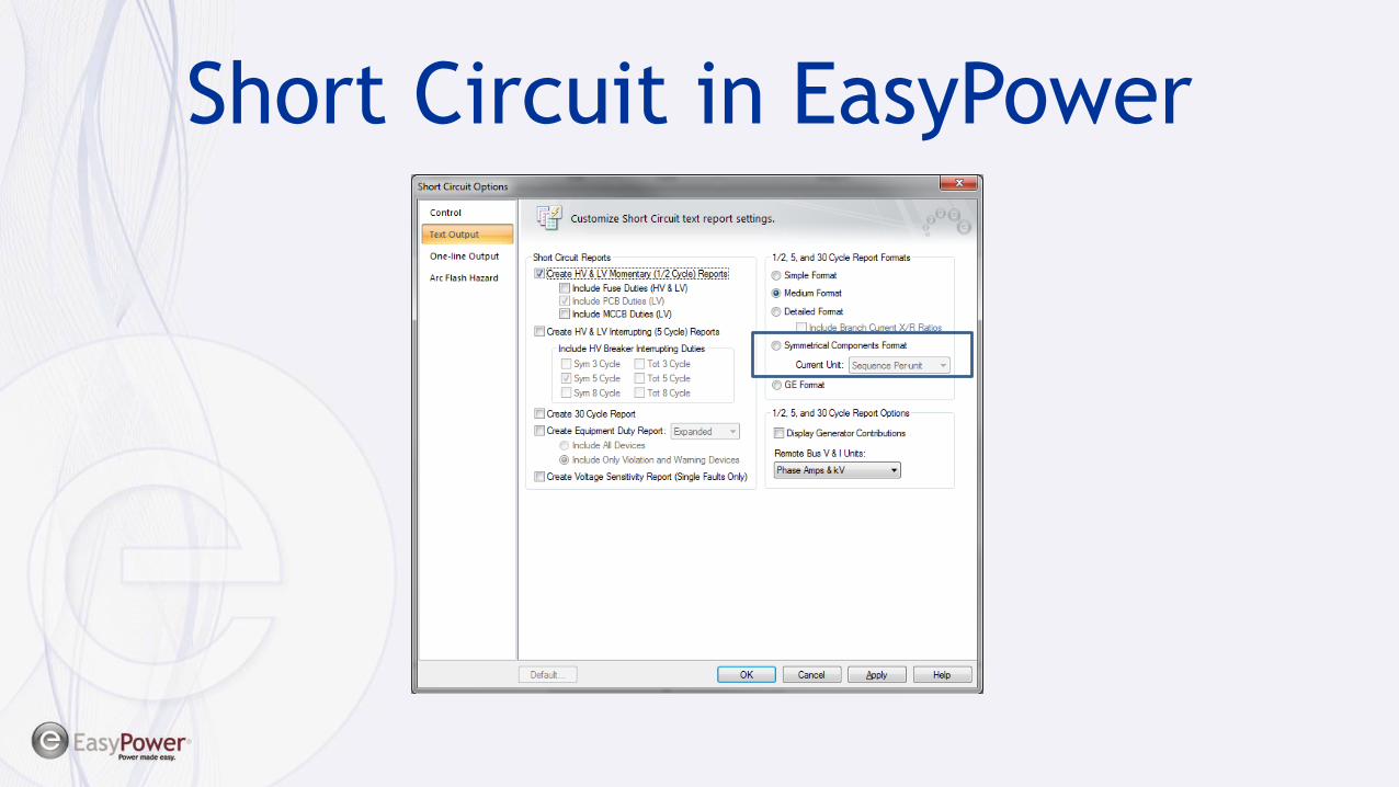
Short Circuit in EasyPower

EasyPower Example
• We’ll look at doing unbalanced fault
calculations in EasyPower
• Look at symmetrical component results