power quality devices improve manufacturing … voltage restorer, or dvr. a dvr will instantly catch...
TRANSCRIPT

62 ABB Review 1/2001
ne way to protect plant
equipment against power grid
disturbances is to install a large-scale,
fast-response Uninterruptible Power
Supply. However, this is tantamount to
overkill for many applications; a UPS is
designed to compensate for complete
loss of power, but most problems arise
from short blips, usually in one phase
only. The answer to this dilemma is the
Dynamic Voltage Restorer, or DVR. A
DVR will instantly catch and compensate
voltage sags, so they won’t even be
noticed.
ABB recently installed two DVRs
which, rated at an impressive 22.5 MVA,
are easily the most powerful ever built.
ABB Integrated Gate Commutated
Thyristor (IGCT) technology makes such
devices possible and gives them their
special attributes – extremely fast
response (<1 ms), higher-than-usual
performance and outstanding reliability.
In summer 2000, just eight months
after receiving the contract, ABB
Industrie AG – in partnership with ABB
High Voltage Technology Ltd – delivered
and put into service two power quality
devices which are among the largest of
their kind anywhere. The main purpose
of the devices – more commonly known
as Dynamic Voltage Restorers (DVR) –
is to compensate for temporary voltage
sags caused by disturbances and faults
in power grids. While such devices have
been built by a variety of manufacturers
in recent years, these DVRs are unique
because of their rating. Designed for
loads of up to 22.5 MVA each, they are
by far the largest units of their kind to
date.
Why voltage sag correction is
important
Most of the disturbances that occur in
power grids are short-time voltage sags.
They can be caused by inrush currents
whenever large transformers are ener-
gized, or by the starting currents of large
motors. The vast majority of voltage sags,
however, are the result of short-circuits
or ground faults somewhere in the grid,
possibly many miles away from where
the voltage sag is experienced. The
duration is usually quite short, about as
long as it takes to disconnect the faulted
line from the grid.
It might be argued that nobody cares
about a voltage sag lasting a trivial 0.1
seconds. At home in the evening, read-
ing or watching TV, you might just notice
the light flicker briefly or a streak race
across the TV screen. But the next moment
everything will have returned to normal,
and an hour later you will probably have
forgotten about it altogether.
It’s a completely different story if you
just happen to be in an elevator when a
voltage sag causes the system control to
trip, and for some reason the device
does not restart automatically. Alarming
the service operator, who then has to
restart the system manually – hopefully
after just a few minutes – can be an
unnerving experience, and one you will
not forget so soon. Even so, nothing
really serious will have happened,
nothing has been damaged, and the
time you have lost will have been no
longer than that spent in your last traffic
jam.
Power quality devicesimprove manufacturingprocess stabilityPeter Daehler, Markus Eichler, Osvin Gaupp, Gerhard Linhofer
If resetting the digital clock after a power blip irritates you, imagine what it feels like to have
a short sag in power hit your manufacturing plant. An interruption of even a few tenths of a
second can easily cost a company thousands of dollars.
O

ABB Review 1/2001 63
For the manufacturing industries, a
voltage sag takes on a quite different
dimension – one which can be summed
up by ‘lost production, lower revenues’.
The search for higher production
efficiency has accelerated the trend
towards automation, not only of single
processes and manufacturing steps but
also of continuous lines combining large
numbers of individual processes and
production steps. Moreover, some of
these processes demand an extremely
stable environment, completely absent
of disturbances, to ensure the very
highest quality and minimum outage.
In either case, even a disturbance lasting
less than 100 milliseconds could result
in several hours of lost production –
or as long as it takes to stabilize the
process conditions.
One way to protect complete manu-
facturing processes or plants from power
grid disturbances is to install large-scale
uninterruptible power supplies capable
of very fast response. However, this is a
rather expensive solution in terms of
up-front investment and operating costs.
Since most power supply disturbances
do not involve a complete loss of
supply, but rather a temporary voltage
drop, usually in just one phase of the
supply line, simple voltage sag compen-
sation would provide sufficient protec-
tion in about 90% of all disturbances
originating in the power grid.
The conditions that called for
voltage sag correction
The manufacturing facility in which the
two mentioned DVRs were installed is of
a complex nature and receives its electric
power from two medium-voltage
feeders. Under very unfavorable weather
conditions the number of flashovers and
line-to-ground faults in the grid can rise
to more than 15 occurrences within a
24-hour period. In 1999 a total of more
than 150 recorded voltage sags had a
considerable impact on production,
calling for an urgent remedy. It was
decided that what was needed was a
pair of power quality devices – one per
feeder – and that they would have to be
delivered in the fastest possible time.
In accordance with the client’s brief,
they had to be up and running within
8 months of the order being placed.
The basic technical specifications were:
■ 22-kV nominal feeder voltage
■ 15-MVA nominal load per feeder,
at a power factor of 0.9 pu
■ Performance:
– Protect the nominal load against
a 3-phase voltage drop of 35% for
a duration of 500 ms
– Protect a load of 22.5 MVA against
a 3-phase voltage drop of 35% for the
shorter duration of 333 ms
– Protect the same loads against 1-phase
voltage drops in excess of 50% for up
to 600 ms
– Time for switching from standby to
boost to be less than 1 ms
The device also had to be ‘expandable’
to permit uprating, should this be
deemed necessary at some time in the
future.
How the requirements are met
What made the short delivery time
possible in the first place was the fact
that a matching hardware platform
AC 1
Rsym
DC+
DC–
CC+
CC–
AC 2
Rsym
DC+
DC–
CC+
CC–
=
The basic building block of the Dynamic Voltage Restorer. Such modules can be
combined to build different converter configurations and high-power DC-DC choppers.
1

64 ABB Review 1/2001
already existed. This allowed modules to
be used that ABB also employs in its
larger standard voltage-source frequency
converters and large medium-voltage
drive systems (ACS 6000). The basic
module is a phase leg for three-level,
neutral-point-clamped converters. These
modules can be combined to build
different converter configurations and
high-power DC-DC choppers. Such a
platform, together with matching signal
interfaces and a versatile, easily
programmable control system, provides
the very high level of flexibility and
adaptability necessary to build units for a
wide range of applications without
having to make any basic changes to the
design.
The active switching elements used
are Integrated Gate Commutated Thyris-
tors (IGCTs) – a kind of advanced Gate
Turn Off Thyristor (GTO). Compared
with GTOs, IGCTs have the advantage of
lower conduction and switching losses,
plus much better switch-off characteris-
tics, allowing a snubberless converter
design.
What set this contract apart from
earlier ones was the amount of energy to
be stored in the DC link capacitor bank,
which serves as the energy storage
device. The challenge here was not so
much the amount of energy itself but
rather the need to design the equipment
such that no kind of internal fault – eg,
a faulty capacitor unit, short circuit or
fault in the converter – could cause any
damage to it besides the failed
component which had instigated the
fault. This task is not at all trivial since
during operation of the device (when a
voltage sag has to be compensated) the
current taken from the capacitor bank is
not low and any current-limiting devices
would have a detrimental effect if the
current is too low, or even interrupted,
as a result of its action. A reasonable
solution was found to be to split the
capacitor bank into two separate groups
and to place a combination of damping
resistors and fuses in strategically
selected locations.
The power quality device
A single-line diagram of the PQ device is
shown in . The main components of
the power circuit and their functions are:
■ DC link with capacitor bank (1). This
also serves as the energy storage medium.
■ Voltage source converter (2) for
voltage sag compensation. It consists of
two NPC phase legs per phase. The
active switching elements are IGCTs.
■ Booster transformer (3), which acts as
the interface between the feeder phases
and the voltage source converter.
2
1
AuxDVR
1
8
2
3
4
7 7
5
6
Grid Load
+ –UDm
dUB
UDp
UG UH
Lim
it of
sup
ply
Lim
it of
sup
ply
~
Single-line diagram of the power quality device
1 DC link with capacitor bank
2 Voltage source converter
3 Booster transformer
4 Damped highpass filter
5 Crowbar
6 Bypass switch
7 Isolation switches
8 Charging unit
UG Grid voltage
UH Load voltage
UDp DC link voltage, positive charge
relative to midpoint
UDm DC link voltage, negative charge
relative to midpoint
dUB Inserted, sag compensating voltage
2
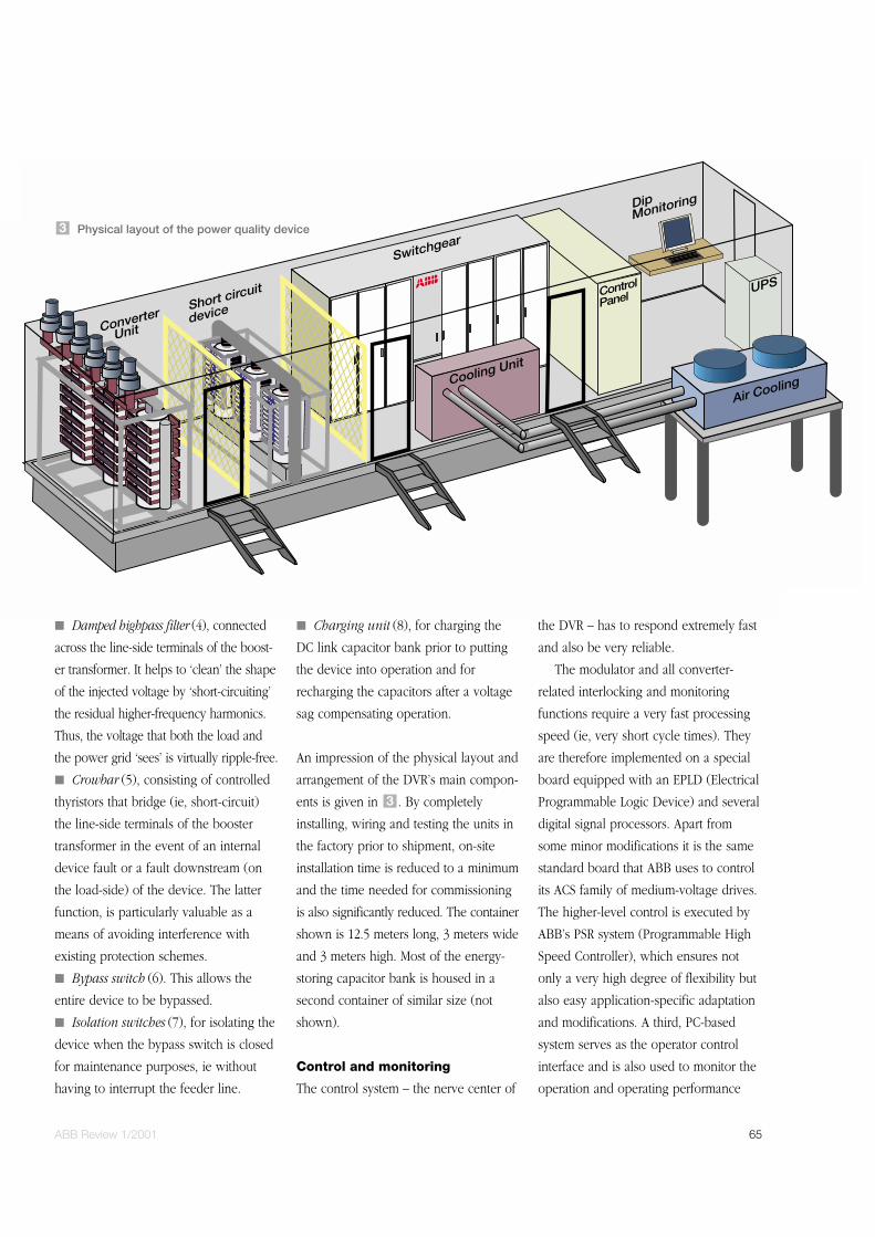
ABB Review 1/2001 65
■ Damped highpass filter (4), connected
across the line-side terminals of the boost-
er transformer. It helps to ‘clean’ the shape
of the injected voltage by ‘short-circuiting’
the residual higher-frequency harmonics.
Thus, the voltage that both the load and
the power grid ‘sees’ is virtually ripple-free.
■ Crowbar (5), consisting of controlled
thyristors that bridge (ie, short-circuit)
the line-side terminals of the booster
transformer in the event of an internal
device fault or a fault downstream (on
the load-side) of the device. The latter
function, is particularly valuable as a
means of avoiding interference with
existing protection schemes.
■ Bypass switch (6). This allows the
entire device to be bypassed.
■ Isolation switches (7), for isolating the
device when the bypass switch is closed
for maintenance purposes, ie without
having to interrupt the feeder line.
■ Charging unit (8), for charging the
DC link capacitor bank prior to putting
the device into operation and for
recharging the capacitors after a voltage
sag compensating operation.
An impression of the physical layout and
arrangement of the DVR’s main compon-
ents is given in . By completely
installing, wiring and testing the units in
the factory prior to shipment, on-site
installation time is reduced to a minimum
and the time needed for commissioning
is also significantly reduced. The container
shown is 12.5 meters long, 3 meters wide
and 3 meters high. Most of the energy-
storing capacitor bank is housed in a
second container of similar size (not
shown).
Control and monitoring
The control system – the nerve center of
the DVR – has to respond extremely fast
and also be very reliable.
The modulator and all converter-
related interlocking and monitoring
functions require a very fast processing
speed (ie, very short cycle times). They
are therefore implemented on a special
board equipped with an EPLD (Electrical
Programmable Logic Device) and several
digital signal processors. Apart from
some minor modifications it is the same
standard board that ABB uses to control
its ACS family of medium-voltage drives.
The higher-level control is executed by
ABB’s PSR system (Programmable High
Speed Controller), which ensures not
only a very high degree of flexibility but
also easy application-specific adaptation
and modifications. A third, PC-based
system serves as the operator control
interface and is also used to monitor the
operation and operating performance
3
Physical layout of the power quality device3
66 ABB Review 1/2001
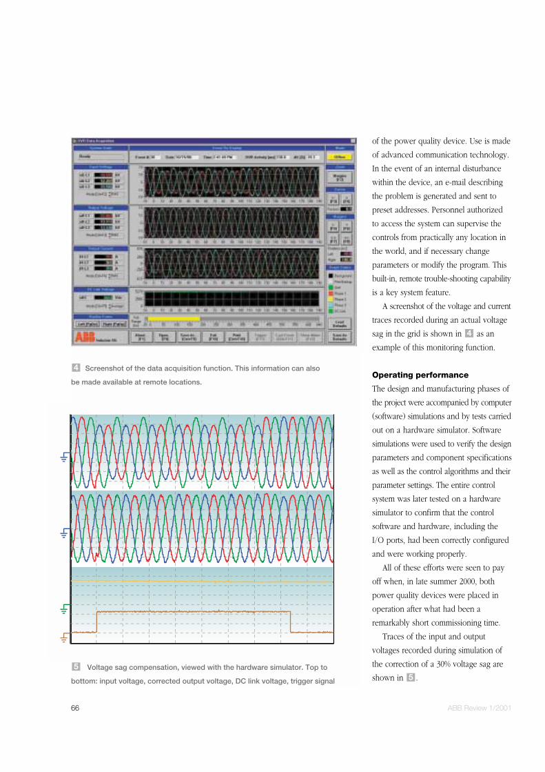
of the power quality device. Use is made
of advanced communication technology.
In the event of an internal disturbance
within the device, an e-mail describing
the problem is generated and sent to
preset addresses. Personnel authorized
to access the system can supervise the
controls from practically any location in
the world, and if necessary change
parameters or modify the program. This
built-in, remote trouble-shooting capability
is a key system feature.
A screenshot of the voltage and current
traces recorded during an actual voltage
sag in the grid is shown in as an
example of this monitoring function.
Operating performance
The design and manufacturing phases of
the project were accompanied by computer
(software) simulations and by tests carried
out on a hardware simulator. Software
simulations were used to verify the design
parameters and component specifications
as well as the control algorithms and their
parameter settings. The entire control
system was later tested on a hardware
simulator to confirm that the control
software and hardware, including the
I/O ports, had been correctly configured
and were working properly.
All of these efforts were seen to pay
off when, in late summer 2000, both
power quality devices were placed in
operation after what had been a
remarkably short commissioning time.
Traces of the input and output
voltages recorded during simulation of
the correction of a 30% voltage sag are
shown in .5
4
Screenshot of the data acquisition function. This information can also
be made available at remote locations.
4
Voltage sag compensation, viewed with the hardware simulator. Top to
bottom: input voltage, corrected output voltage, DC link voltage, trigger signal
5

ABB Review 1/2001 67
shows the same traces, but taken
from a recording in the actual installation
when a genuine voltage sag of similar
magnitude took place shortly after com-
missioning. If the device had not been in
operation, such a voltage sag would have
had a negative impact on production. It
can also be seen that the voltage compen-
sation takes place extremely quickly, ie
in less than one millisecond, which is
faster than is actually needed or
specified. This is made possible by the
unique feed-forward control used for this
kind of application. It almost completely
does away with the delay and settling
time that would be unavoidable if a more
conventional control algorithm were used.
Last but not least, it has to be
emphasized that the specifications were
considered as guidelines and minimum
requirements for the devices. The sag
compensation, for example, is not limited
to the specified value. If a three-phase
sag happens to be larger than 35% it will
still be compensated – not for 500 ms,
but for as long as the energy storing
capacitor bank can supply the power. And
if the sag is smaller, the system provides
protection for up to 600 ms, so that many
consecutive voltage sags are compensated.
In addition, the nominal DC link voltage
is lower than its maximum permissible
value, so the DC capacitor bank can also
absorb a certain amount of energy. This
enables not only voltage sags to be
compensated but also some temporary
overvoltages (voltage swells) as well.
shows the voltage sag versus dis-
turbance duration capability of the system
for 1-phase, 2-phase and 3-phase sags.
7
6 1.0
0.5
0
–0.5
–1.0
Uin
[pu
]
1.0
0.5
0
–0.5
–1.0
Uo
ut[
pu
]
140120100806040200–20
t [ms]
Voltage sag compensation in the actual installation. The top recording
shows the input voltage, that below it the corrected output voltage.
Uin Input voltage
Uout Output voltage
t Time
6
100
90
80
30
40
50
60
70
U[%
]
0 100 200 300 400 500 600
F [ms]
1-phase %2-phase %3-phase %
Protection capability of the system. Voltage sag (U) versus fault duration (F)7
68 ABB Review 1/2001
Conclusions
Power quality devices with DVR
functionality are not intended to replace
uninterruptible power supplies.
However, they offer excellent protection
for complex manufacturing processes
against most disturbances occurring in
power grids. They are also very rugged
and reliable, and are capable of
extremely fast response, plus they
require practically no maintenance. And
since they can be built with relatively
high ratings, they can be employed
across industry - not only to protect
individual production lines but also
entire factories or industrial parks. Just as
importantly, they do not interfere with
existing protection schemes by limiting
fault currents when faults occur
downstream. They can therefore be
installed without requiring modifications
to the existing equipment.
For further information please visit
http://www.abb.com/powerelectronics
Authors
Peter DaehlerMarkus EichlerOsvin GauppGerhard LinhoferABB Industrie AGCH-5300 TurgiSwitzerlandAddress for questions and inquiriesE-mail: [email protected]: +41 56 299 2090
References[1] H. M. Stillmann: IGCTs - megawatt power switches for medium voltage applications. ABB Review 3/97, 12-17.
[2] P. K. Steimer, et al: IGCT - a new, emerging technology for high power, low cost inverters. ABB Review 5/98, 34-42.
[3] P. Daehler, R. Affolter: Requirements and solutions for dynamic voltage restorers. IEEE Power Engineering Society, Winter Meeting,
Singapore, Jan 2000.
[4] W. Raithmayr, et al: Customer reliability improvement with a DVR or a DUPS. Power World Conference, 1998.
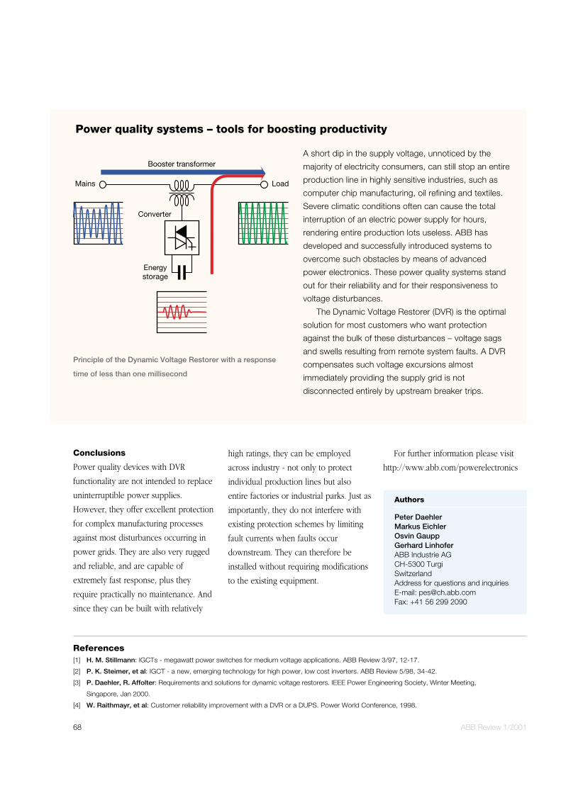
A short dip in the supply voltage, unnoticed by the
majority of electricity consumers, can still stop an entire
production line in highly sensitive industries, such as
computer chip manufacturing, oil refining and textiles.
Severe climatic conditions often can cause the total
interruption of an electric power supply for hours,
rendering entire production lots useless. ABB has
developed and successfully introduced systems to
overcome such obstacles by means of advanced
power electronics. These power quality systems stand
out for their reliability and for their responsiveness to
voltage disturbances.
The Dynamic Voltage Restorer (DVR) is the optimal
solution for most customers who want protection
against the bulk of these disturbances – voltage sags
and swells resulting from remote system faults. A DVR
compensates such voltage excursions almost
immediately providing the supply grid is not
disconnected entirely by upstream breaker trips.
Power quality systems – tools for boosting productivity
Booster transformer
Mains Load
Converter
Energystorage
Principle of the Dynamic Voltage Restorer with a response
time of less than one millisecond