design of dvr against voltage sags & swell using matrix ... · a dynamic voltage restorer (dvr)...
TRANSCRIPT
International Journal of Research and Scientific Innovation (IJRSI) | Volume IV, Issue VI, June 2017 | ISSN 2321–2705
www.rsisinternational.org Page 64
Design of DVR against Voltage Sags & Swell Using
Matrix Converter Namrata Gupta
#, Manish Awasthi
*
Department of Electrical Engineering, RGPV University/Jawaharlal Nehru College of technology, Rewa, India
Abstract— This paper is describes the using of dynamic voltage
restorer (DVR) in the terms of mitigate voltage sagging and
swelling with low voltage distribution systems. A dynamic
voltage restorer (DVR) is based on the dqo algorithm. This
scheme is very effectual to notice any trouble in low voltage
distribution systems. Simulation results using Matlab/Simulink
are existing to make sure the usefulness of the proposed scheme.
Keywords— dynamic voltage restorer (DVR), voltage sags,
voltage swells, matrix converter, matlab/simulink.
I. INTRODUCTION
aults at either the transmission or distribution level may
cause voltage sag or swell in the entire system or a large
part of it. Also, under heavy load conditions, a significant
voltage drop may occur in the system. Voltage sags can occur
at any instant of time, with amplitudes ranging from 10 - 90%
and a duration lasting for half a cycle to one minute [1].
There are different methods to mitigate voltage sags and
swells, but the use of a convention Power device is measured
to be the well-organized method. The concept of convention
Power was introduced by N.G. Hingorani in 1995.
A. Power Quality Problem
Power Quality problems cover a wide ranges of conflicts such
as voltage sags/swells, impulse transient, flicker, harmonics
distortion and interruptions. These sags/swells have mainly
importance in power quality problems in the power
distribution system. The power quality troubles are
performing its impact on a variety of customer like Industries,
commercial, residential. Most important quality problems are
voltage sag, swell, transients, and harmonics, so on.
The power quality troubles are performing its impact on a
variety of customer include Industries, Commercial as well as
residential. Most important quality problems are voltage sag,
swell, transients and harmonics and so on. Power quality
phenomenon can be defined as the variation of the current and
voltage from its ideal waveform.
Power Quality has developed into an unsafe issue in highly
automated industries and sensitive load centers. The voltage
disturbances in the form of voltage sag, swell, flicker and
harmonics can cause huge financial losses. In the past few
years, power system solutions have been avoiding these
troubles. The main difficulties of poor power quality like
voltage sag for sensitive loads can be improved solution based
upon Dynamic Voltage Restorer (DVR).
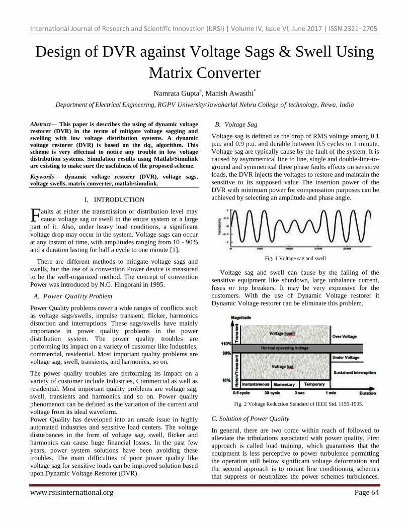
B. Voltage Sag
Voltage sag is defined as the drop of RMS voltage among 0.1
p.u. and 0.9 p.u. and durable between 0.5 cycles to 1 minute.
Voltage sag are typically cause by the fault of the system. It is
caused by asymmetrical line to line, single and double-line-to-
ground and symmetrical three phase faults effects on sensitive
loads, the DVR injects the voltages to restore and maintain the
sensitive to its supposed value The insertion power of the
DVR with minimum power for compensation purposes can be
achieved by selecting an amplitude and phase angle.
Fig. 1 Voltage sag and swell
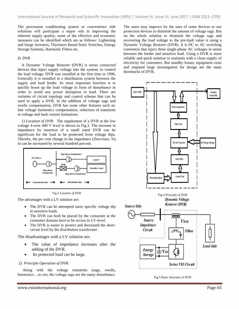
Voltage sag and swell can cause by the failing of the
sensitive equipment like shutdown, large unbalance current,
fuses or trip breakers. It may be very expensive for the
customers. With the use of Dynamic Voltage restorer it
Dynamic Voltage restorer can be eliminate this problem.
Fig. 2 Voltage Reduction Standard of IEEE Std. 1159-1995.
C. Solution of Power Quality
In general, there are two come within reach of followed to
alleviate the tribulations associated with power quality. First
approach is called load training, which guarantees that the
equipment is less perceptive to power turbulence permitting
the operation still below significant voltage deformation and
the second approach is to mount line conditioning schemes
that suppress or neutralizes the power schemes turbulences.
F
International Journal of Research and Scientific Innovation (IJRSI) | Volume IV, Issue VI, June 2017 | ISSN 2321–2705
www.rsisinternational.org Page 65
The procession conditioning system or convenience side
solutions will participate a major role in improving the
inherent supply quality; some of the effective and economic
measures can be identified which are as follows: Lightening
and Surge Arresters, Thyristors Based Static Switches, Energy
Storage Systems, Harmonic Filters etc.
D. DVR
A Dynamic Voltage Restorer (DVR) is series connected
devices that inject supply voltage into the system; to control
the load voltage. DVR was installed at the first time in 1996.
Generally it is installed in a distribution system between the
supply and load feeder. Its most important function is to
quickly boost up the load voltage in form of disturbance in
order to avoid any power disruption in load. There are
varieties of circuit topology and control scheme that can be
used to apply a DVR. In the addition of voltage sags and
swells compensation, DVR has some other features such as:
line voltage harmonics compensation, reduction of transients
in voltage and fault current limitations.
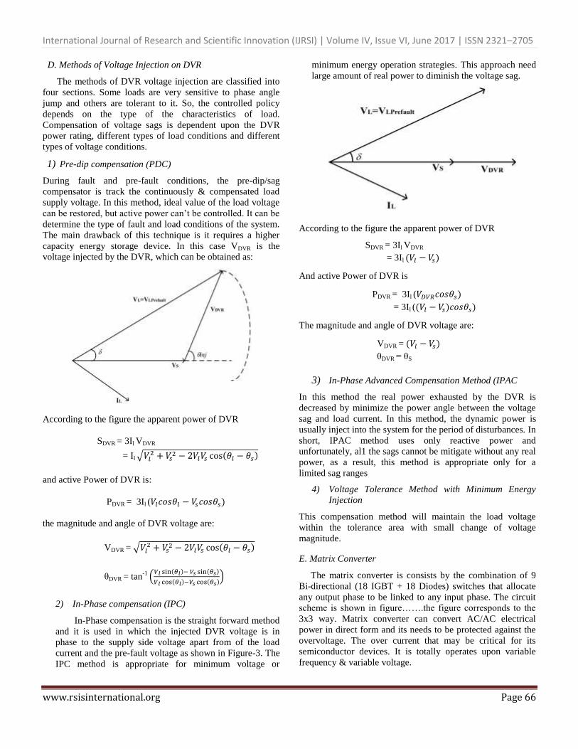
1) Location of DVR: The supplement of a DVR at the low
voltage 4-wire 440 V level is shown in Fig.3. The increase in
impedance by insertion of a small rated DVR can be
significant for the load to be protected from voltage dips.
Thereby, the per cent change in the impedance (Zincrease, %)
in can be increased by several hundred percent.
Fig.3 Location of DVR
The advantages with a LV solution are:
The DVR can be attempted more specific voltage dip
in sensitive loads.
The DVR can both be placed by the consumer at the
consumer domain have to be access in LV-level.
The DVR is easier to protect and decreased the short-
circuit level by the distribution transformer
The disadvantages with a LV solution are:
The value of impedance increases after the
adding of the DVR.
Its protected load can be large.
2) Principle Operation of DVR:
Along with the voltage transients (sags, swells,
harmonics…so on), the voltage sags are the many disturbance.
The users may improve by the uses of some devices or use
protection devices to diminish the amount of voltage sags. But
on the whole solution to diminish the voltage sags and
recovering the load voltage to the pre-fault value is using a
Dynamic Voltage Restorer (DVR). It is DC to AC switching
converters that inject three single-phase AC voltages in series
between the feeder and sensitive load. Using a DVR is more
reliable and quick solution to maintain with a clean supply of
electricity for customers. But standby losses, equipment costs
and required large investigation for design are the main
drawbacks of DVR.
Fig.4 Principle of DVR
Fig.5 Basic Structure of DVR
International Journal of Research and Scientific Innovation (IJRSI) | Volume IV, Issue VI, June 2017 | ISSN 2321–2705
www.rsisinternational.org Page 66
D. Methods of Voltage Injection on DVR
The methods of DVR voltage injection are classified into
four sections. Some loads are very sensitive to phase angle
jump and others are tolerant to it. So, the controlled policy
depends on the type of the characteristics of load.
Compensation of voltage sags is dependent upon the DVR
power rating, different types of load conditions and different
types of voltage conditions.
1) Pre-dip compensation (PDC)
During fault and pre-fault conditions, the pre-dip/sag
compensator is track the continuously & compensated load
supply voltage. In this method, ideal value of the load voltage
can be restored, but active power can’t be controlled. It can be
determine the type of fault and load conditions of the system.
The main drawback of this technique is it requires a higher
capacity energy storage device. In this case VDVR is the
voltage injected by the DVR, which can be obtained as:
According to the figure the apparent power of DVR
SDVR = 3Il VDVR
= Il √
( )
and active Power of DVR is:
PDVR = 3Il ( )
the magnitude and angle of DVR voltage are:
VDVR = √
( )
θDVR = tan-1 .
( ) ( )
( ) ( )/
2) In-Phase compensation (IPC)
In-Phase compensation is the straight forward method
and it is used in which the injected DVR voltage is in
phase to the supply side voltage apart from of the load
current and the pre-fault voltage as shown in Figure-3. The
IPC method is appropriate for minimum voltage or
minimum energy operation strategies. This approach need
large amount of real power to diminish the voltage sag.
According to the figure the apparent power of DVR
SDVR = 3Il VDVR
= 3Il ( )
And active Power of DVR is
PDVR = 3Il ( )
= 3Il (( ) )
The magnitude and angle of DVR voltage are:
VDVR = ( )
θDVR = θS
3) In-Phase Advanced Compensation Method (IPAC
In this method the real power exhausted by the DVR is
decreased by minimize the power angle between the voltage
sag and load current. In this method, the dynamic power is
usually inject into the system for the period of disturbances. In
short, IPAC method uses only reactive power and
unfortunately, al1 the sags cannot be mitigate without any real
power, as a result, this method is appropriate only for a
limited sag ranges
4) Voltage Tolerance Method with Minimum Energy
Injection
This compensation method will maintain the load voltage
within the tolerance area with small change of voltage
magnitude. E. Matrix Converter
The matrix converter is consists by the combination of 9
Bi-directional (18 IGBT + 18 Diodes) switches that allocate
any output phase to be linked to any input phase. The circuit
scheme is shown in figure…….the figure corresponds to the
3x3 way. Matrix converter can convert AC/AC electrical
power in direct form and its needs to be protected against the
overvoltage. The over current that may be critical for its
semiconductor devices. It is totally operates upon variable
frequency & variable voltage.
International Journal of Research and Scientific Innovation (IJRSI) | Volume IV, Issue VI, June 2017 | ISSN 2321–2705
www.rsisinternational.org Page 67
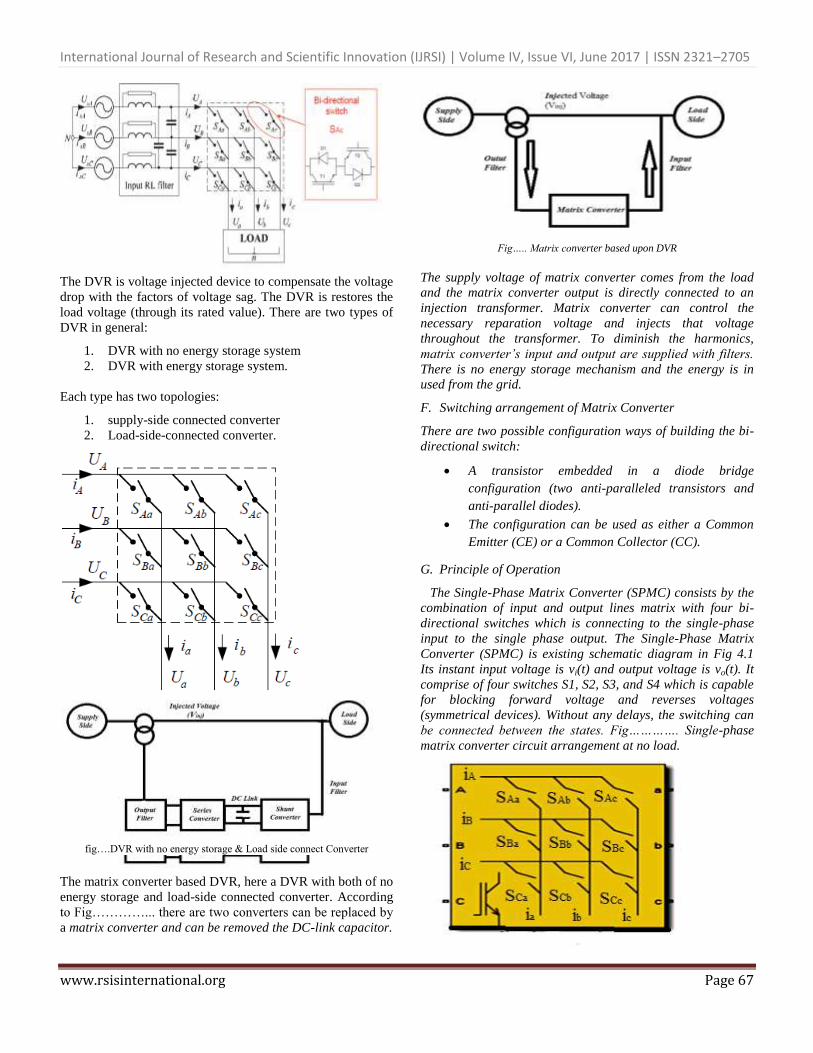
The DVR is voltage injected device to compensate the voltage
drop with the factors of voltage sag. The DVR is restores the
load voltage (through its rated value). There are two types of
DVR in general:
1. DVR with no energy storage system
2. DVR with energy storage system.
Each type has two topologies:
1. supply-side connected converter
2. Load-side-connected converter.
fig….DVR with no energy storage & Load side connect Converter
The matrix converter based DVR, here a DVR with both of no
energy storage and load-side connected converter. According
to Fig…………... there are two converters can be replaced by
a matrix converter and can be removed the DC-link capacitor.
Fig….. Matrix converter based upon DVR
The supply voltage of matrix converter comes from the load
and the matrix converter output is directly connected to an
injection transformer. Matrix converter can control the
necessary reparation voltage and injects that voltage
throughout the transformer. To diminish the harmonics,
matrix converter’s input and output are supplied with filters.
There is no energy storage mechanism and the energy is in
used from the grid.
F. Switching arrangement of Matrix Converter
There are two possible configuration ways of building the bi-
directional switch:
A transistor embedded in a diode bridge
configuration (two anti-paralleled transistors and
anti-parallel diodes).
The configuration can be used as either a Common
Emitter (CE) or a Common Collector (CC).
G. Principle of Operation
The Single-Phase Matrix Converter (SPMC) consists by the
combination of input and output lines matrix with four bi-
directional switches which is connecting to the single-phase
input to the single phase output. The Single-Phase Matrix
Converter (SPMC) is existing schematic diagram in Fig 4.1
Its instant input voltage is vi(t) and output voltage is vo(t). It
comprise of four switches S1, S2, S3, and S4 which is capable
for blocking forward voltage and reverses voltages
(symmetrical devices). Without any delays, the switching can
be connected between the states. Fig…………. Single-phase
matrix converter circuit arrangement at no load.
International Journal of Research and Scientific Innovation (IJRSI) | Volume IV, Issue VI, June 2017 | ISSN 2321–2705
www.rsisinternational.org Page 68
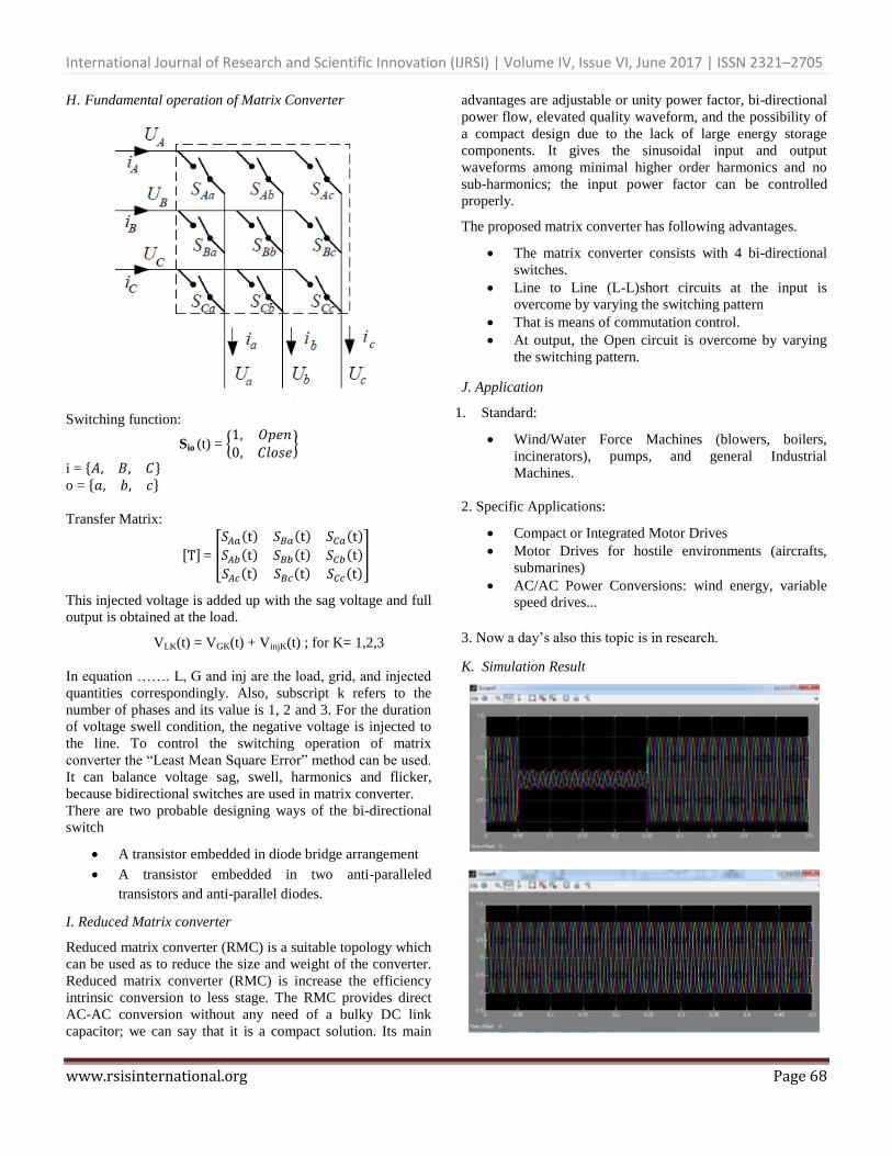
H. Fundamental operation of Matrix Converter
Switching function:
Sio (t) = {
}
i = * + o = * +
Transfer Matrix:
, - = [
( ) ( ) ( )
( ) ( ) ( )
( ) ( ) ( )]
This injected voltage is added up with the sag voltage and full
output is obtained at the load.
VLK(t) = VGK(t) + VinjK(t) ; for K= 1,2,3
In equation ……. L, G and inj are the load, grid, and injected
quantities correspondingly. Also, subscript k refers to the
number of phases and its value is 1, 2 and 3. For the duration
of voltage swell condition, the negative voltage is injected to
the line. To control the switching operation of matrix
converter the “Least Mean Square Error” method can be used.
It can balance voltage sag, swell, harmonics and flicker,
because bidirectional switches are used in matrix converter.
There are two probable designing ways of the bi-directional
switch
A transistor embedded in diode bridge arrangement
A transistor embedded in two anti-paralleled
transistors and anti-parallel diodes.
I. Reduced Matrix converter
Reduced matrix converter (RMC) is a suitable topology which
can be used as to reduce the size and weight of the converter.
Reduced matrix converter (RMC) is increase the efficiency
intrinsic conversion to less stage. The RMC provides direct
AC-AC conversion without any need of a bulky DC link
capacitor; we can say that it is a compact solution. Its main
advantages are adjustable or unity power factor, bi-directional
power flow, elevated quality waveform, and the possibility of
a compact design due to the lack of large energy storage
components. It gives the sinusoidal input and output
waveforms among minimal higher order harmonics and no
sub-harmonics; the input power factor can be controlled
properly.
The proposed matrix converter has following advantages.
The matrix converter consists with 4 bi-directional
switches.
Line to Line (L-L)short circuits at the input is
overcome by varying the switching pattern
That is means of commutation control.
At output, the Open circuit is overcome by varying
the switching pattern.
J. Application
1. Standard:
Wind/Water Force Machines (blowers, boilers,
incinerators), pumps, and general Industrial
Machines.
2. Specific Applications:
Compact or Integrated Motor Drives
Motor Drives for hostile environments (aircrafts,
submarines)
AC/AC Power Conversions: wind energy, variable
speed drives...
3. Now a day’s also this topic is in research. K. Simulation Result

International Journal of Research and Scientific Innovation (IJRSI) | Volume IV, Issue VI, June 2017 | ISSN 2321–2705
www.rsisinternational.org Page 69
II. CONCLUSIONS
The modeling and simulation of Dynamic voltage
Restorer (DVR) are presented by the usage of MATLAB/
SIMULATION. The simulation shows the satisfactory
performance of DVR in The case of voltage sag and swell.
Simulation result ma shows effective custom power of
voltage sag and swell. The simulation carried out the better
voltage regulation capability of DVR. Dynamic voltage
Restorer (DVR) is handling both balanced and unbalanced
position without any problem.
The main advantage of DVR is consider To be
efficient result has been provided with low cost, fast
response, compact size and its control is simple. As a result
This DVR model can use to restore load voltage in The
case of balance and unbalance condition of voltage sags
and swells.
ACKNOWLEDGMENT
I express my thanks to Almighty for providing me
inspiration, strength, energy and patience to start and
accomplish my work with the support of all concerned a
few of them I am trying to acknowledge. I heartily and
courteously thank my guide Mr MANISH AWASTHI who
has been main source of inspiration to guide this work
throughout the course of the work. He is a person with
tremendous force, resourceful, creativity and of friendly
nature. He proved hirself to be the best guide by the way of
inspiring to work in right direction, presenting research
papers in seminars and conferences. I thank Mr MANISH
AWASTHI, Department of Electrical Engineering
Jawaharlal Nehru college of engineering & technology,
Rewa (M.P) For helping me in all ways for registering me
as M.Tech. Student, for providing laboratory facilities. I am
also thankful to for their assistance and help. I express my
thanks to all my colleagues for their help and throughout
support. Last but not least, I express my thanks to my
family for all support, inspiration and love provided to me
with all inconveniencies caused because of my engagement
in this work.
REFERENCES
[1]. C. Benachaiba, S. Dib O. Abdelkhalek, B. Ferdi. Voltage quality improvement using DVR.
[2]. IEEE Std. 1159-1995. Recommended Practice for Monitoring
Electric Power Quality. [3]. J.G. Nielsen, M. Newman, H. Nielsen and F. Blaabjerg. 2004.
Control and testing of a dynamic voltage restorer (DVR) at
medium voltage level. IEEE Trans. Power Electron. 19(3): 806
May
[4]. T. Devaraju, V.C. Veera Reddy, M. Vijaya Kumar performance of
DVR under different voltage sag and swell condition [5]. B.H. Li, S.S. Choi, D.M. Vilathgamuwa, “Design
Considerations on the Line-Side Filter Used in the Dynamic
Voltage Restorer”, IEE Proc. Gener. Transmission Distrib., Issue 1, Vol. 148, pp. 1-7, Jan. 2001.
[6]. M. N. Tandjaoui, C. Benachaiba, O. Abdelkhalek Mitigation of
voltage sags/swells unbalanced in low voltage distribution systems [7]. A. Imam, T. Habetler, R. Harley and D. Divan, “Condition
monitoring of electrolytic capacitor in power electronic circuits
using adaptive filter modeling,” IEEE 36th Annual Power Electronics Specialists Conference, 2005, pp. 601-607.
[8]. B. Wang and G. Venkataramanan, “Dynamic Voltage Restorer
utilizing a matrix converter and flywheel energy storage,” IEEE Transactions on Industry Applications, Jan-Feb 2009, vol. 45, pp.
222-231.