power-on and power-off proceduresjang/teaching/nextmobcom_files/power-on and... · rxlevmin is a...
TRANSCRIPT

POWER-ON AND POWER-OFF PROCEDURES
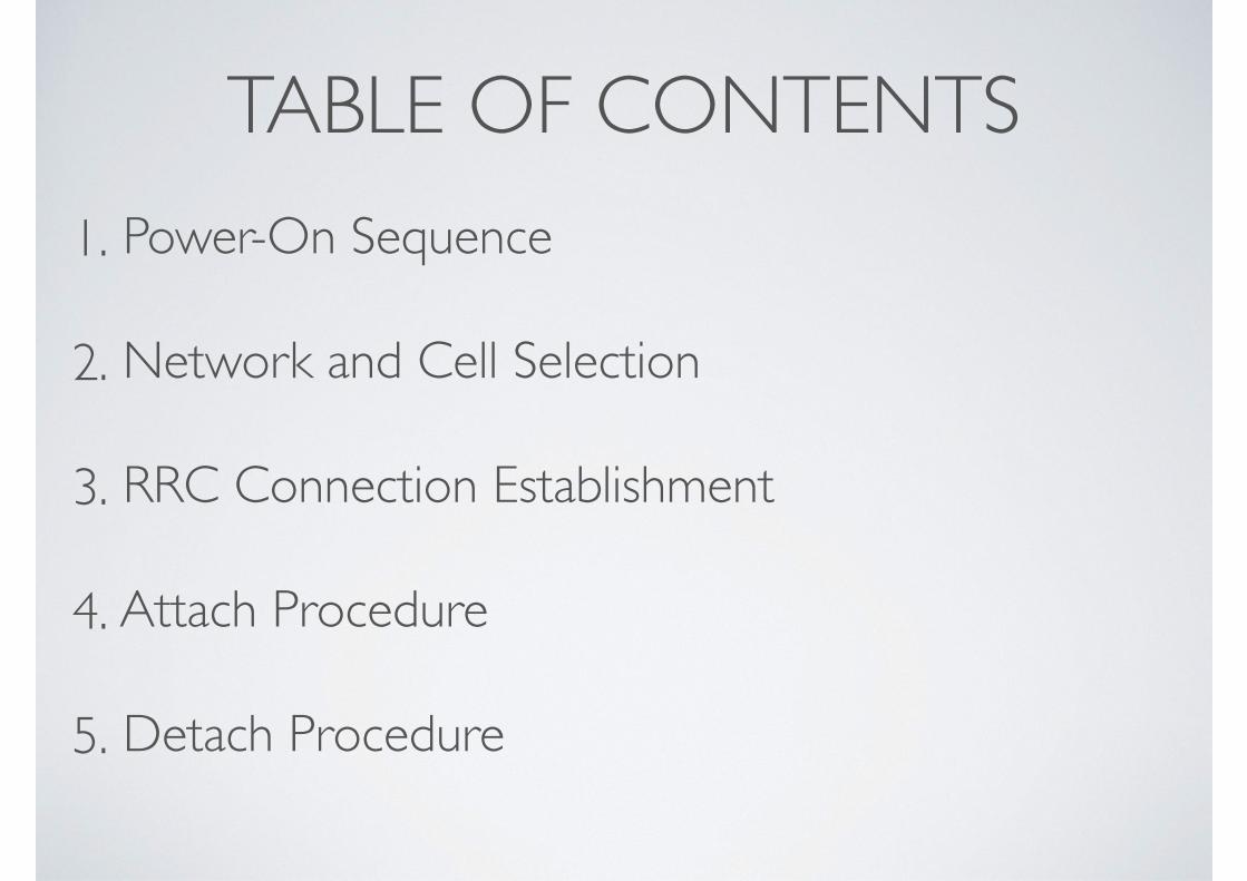
TABLE OF CONTENTS1. Power-On Sequence
2. Network and Cell Selection
3. RRC Connection Establishment
4. Attach Procedure
5. Detach Procedure
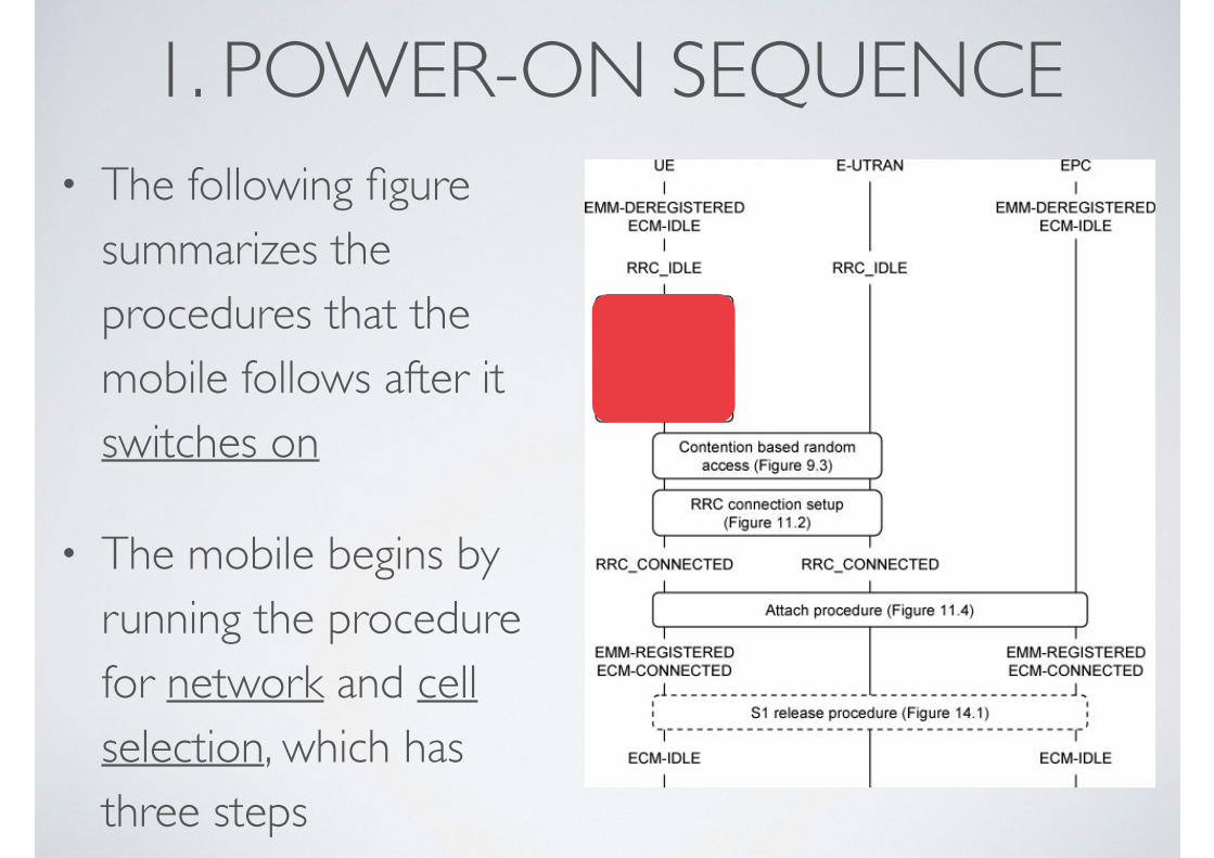
1. POWER-ON SEQUENCE• The following figure
summarizes the procedures that the mobile follows after it switches on
• The mobile begins by running the procedure for network and cell selection, which has three steps
• 1st
step
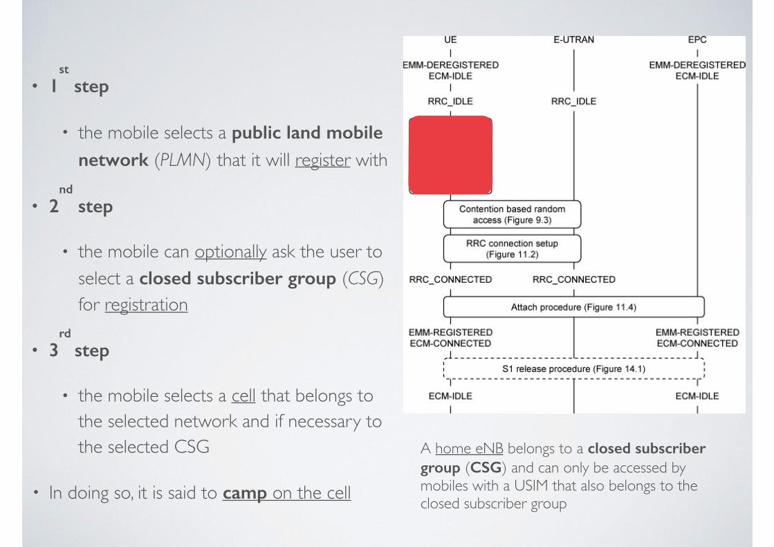
• the mobile selects a public land mobile network (PLMN) that it will register with
• 2nd
step
• the mobile can optionally ask the user to select a closed subscriber group (CSG) for registration
• 3rd
step
• the mobile selects a cell that belongs to the selected network and if necessary to the selected CSG
• In doing so, it is said to camp on the cell
A home eNB belongs to a closed subscriber group (CSG) and can only be accessed by mobiles with a USIM that also belongs to the closed subscriber group
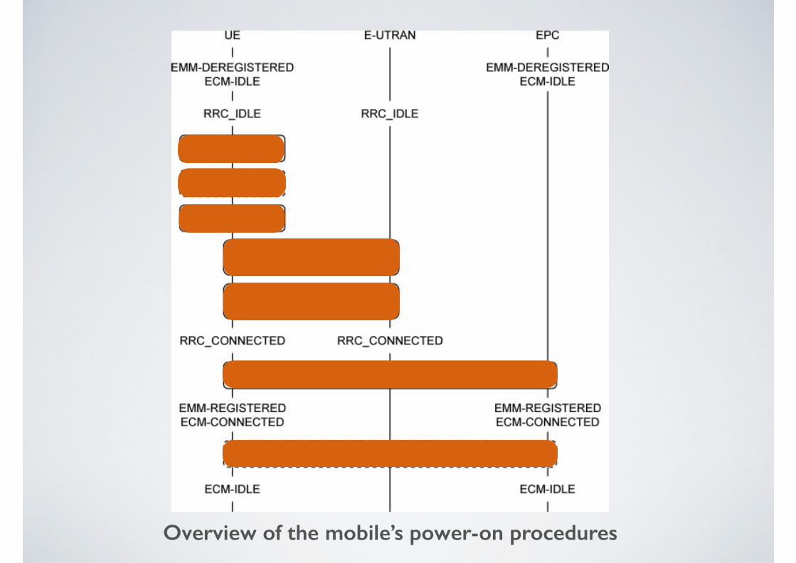
Overview of the mobile’s power-on procedures
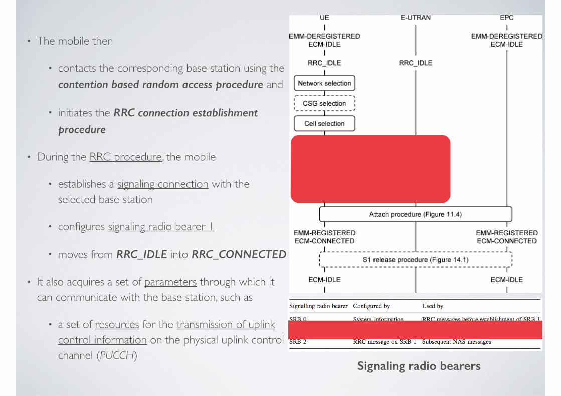
• The mobile then
• contacts the corresponding base station using the contention based random access procedure and
• initiates the RRC connection establishment procedure
• During the RRC procedure, the mobile
• establishes a signaling connection with the selected base station
• configures signaling radio bearer 1
• moves from RRC_IDLE into RRC_CONNECTED
• It also acquires a set of parameters through which it can communicate with the base station, such as
• a set of resources for the transmission of uplink control information on the physical uplink control channel (PUCCH)
Signaling radio bearers
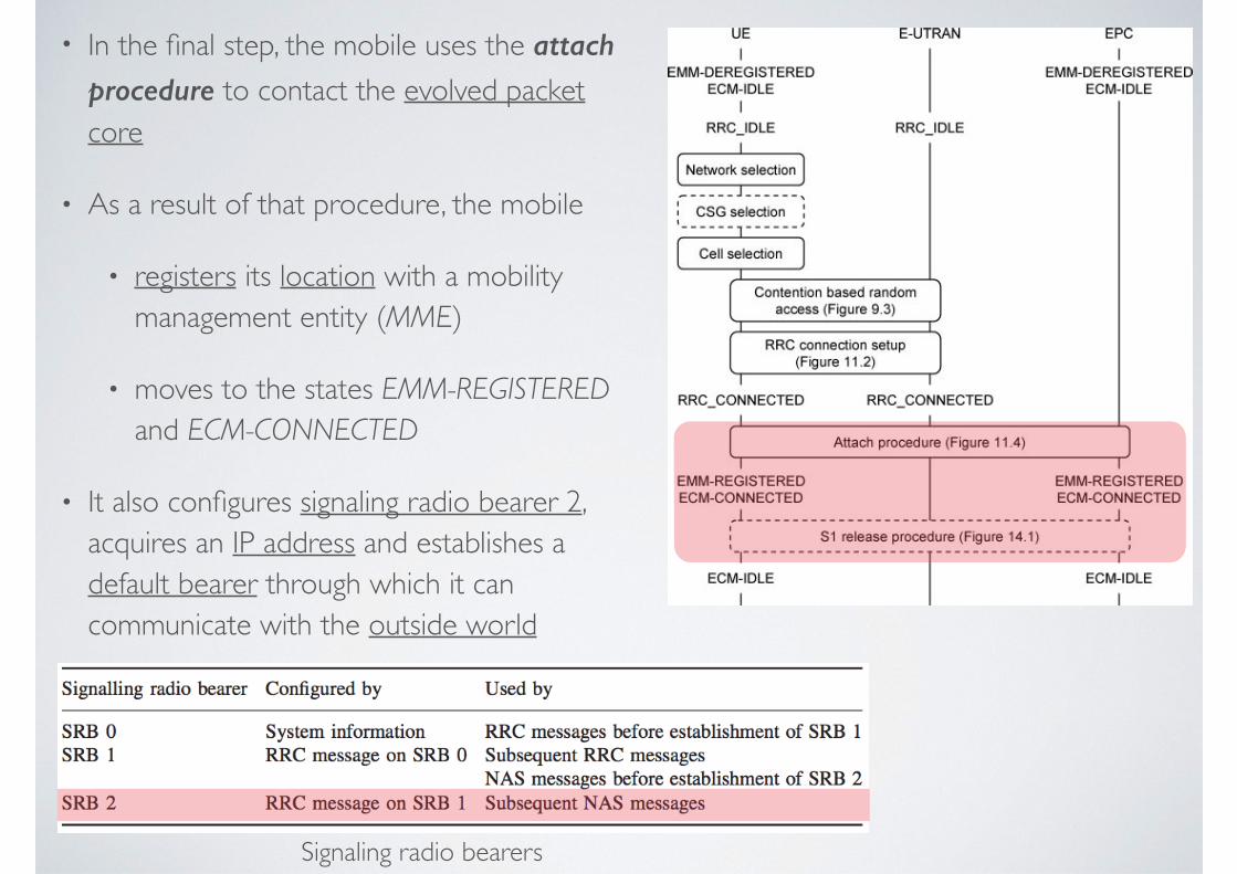
• In the final step, the mobile uses the attach procedure to contact the evolved packet core
• As a result of that procedure, the mobile
• registers its location with a mobility management entity (MME)
• moves to the states EMM-REGISTERED and ECM-CONNECTED
• It also configures signaling radio bearer 2, acquires an IP address and establishes a default bearer through which it can communicate with the outside world
Signaling radio bearers
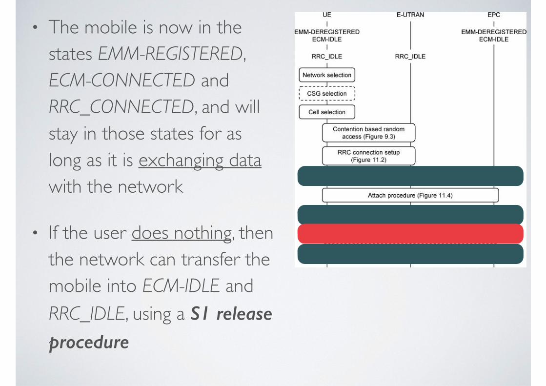
• The mobile is now in the states EMM-REGISTERED, ECM-CONNECTED and RRC_CONNECTED, and will stay in those states for as long as it is exchanging data with the network
• If the user does nothing, then the network can transfer the mobile into ECM-IDLE and RRC_IDLE, using a S1 release procedure
2. NETWORK AND CELL SELECTION
2.1 Network Selection
2.2 Closed Subscriber Group Selection
2.3 Cell Selection
2.1 NETWORK SELECTION• In the network selection procedure, the mobile selects a public land mobile network
(PLMN) that it will register with
• To start the procedure, the mobile equipment
• interrogates the USIM
• retrieves the globally unique temporary identity (GUTI) that it was using when last switched on
• retrieves the tracking area identity in which it was registered
• From these quantities, it can identify the corresponding network, which is known as the registered PLMN
• The mobile runs the CSG and cell selection procedures described below, in the hope of finding a suitable cell that belongs to the registered PLMN
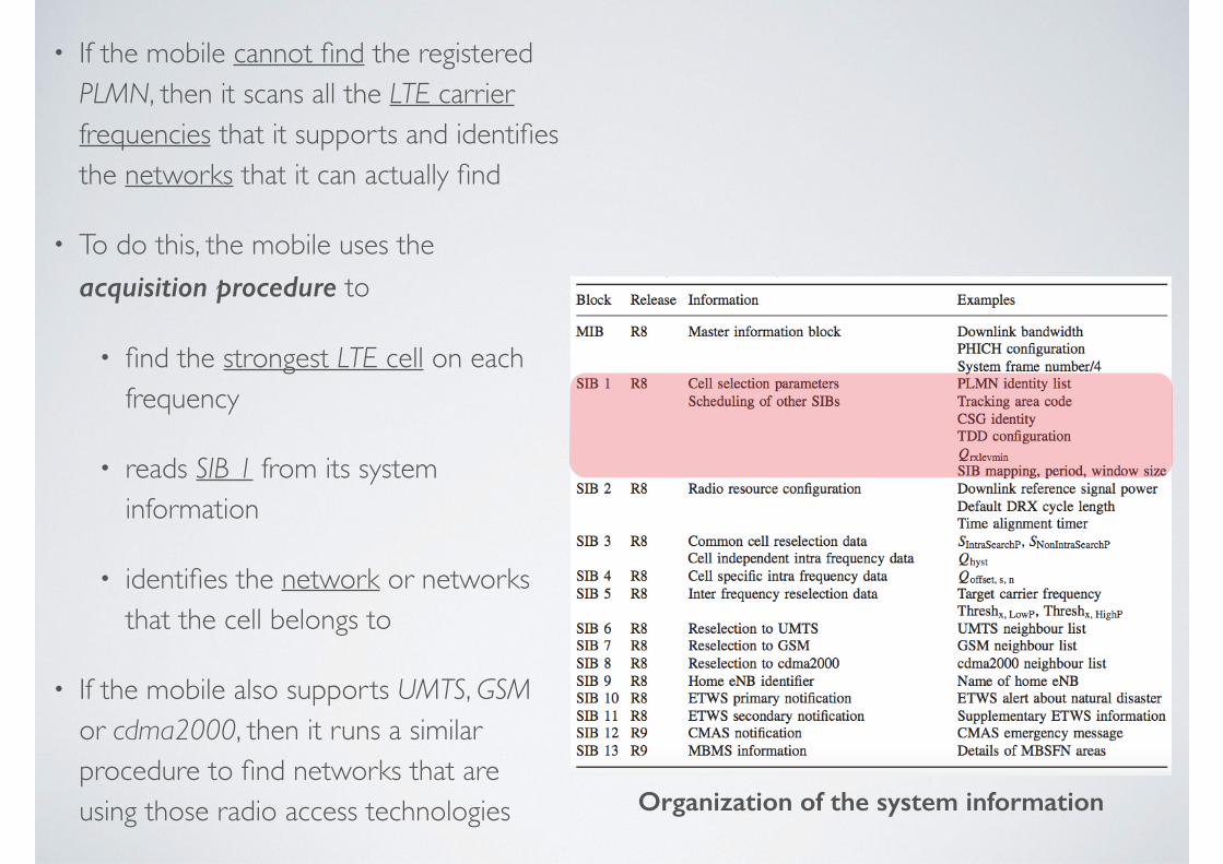
• If the mobile cannot find the registered PLMN, then it scans all the LTE carrier frequencies that it supports and identifies the networks that it can actually find
• To do this, the mobile uses the acquisition procedure to
• find the strongest LTE cell on each frequency
• reads SIB 1 from its system information
• identifies the network or networks that the cell belongs to
• If the mobile also supports UMTS, GSM or cdma2000, then it runs a similar procedure to find networks that are using those radio access technologies Organization of the system information
• There are then two network selection modes, automatic and manual
• automatic mode
• the mobile runs in priority order through a list of networks that it should treat as home PLMNs, together with an associated list of radio access technologies (these lists are both stored on the USIM)
• when it encounters a network that it has previously found, the mobile runs the CSG and cell selection procedures in the manner described below
• If the mobile cannot find a home PLMN, then
• it repeats the procedure using first any user-defined list of networks and radio access technologies, and then any operator-defined list
• If it cannot find any of those networks, then
• the mobile tries to select a cell from any network that is available
• it enters a limited service state, in which it can only make emergency calls and receive warnings from the earthquake and tsunami warning system
• manual mode
• the mobile presents the user with the list of networks that it has found, using the same priority order as in automatic mode
• the user selects a preferred network and the mobile proceeds to the CSG and cell selection procedures as before
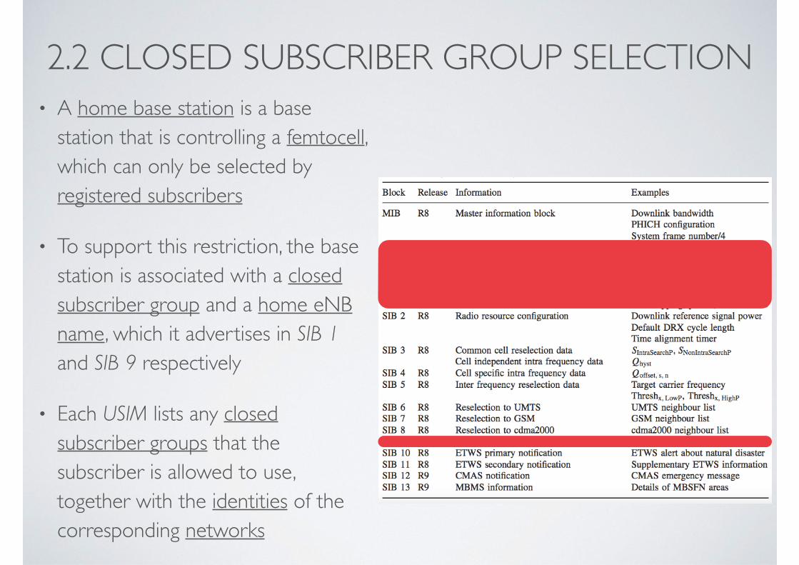
2.2 CLOSED SUBSCRIBER GROUP SELECTION• A home base station is a base
station that is controlling a femtocell, which can only be selected by registered subscribers
• To support this restriction, the base station is associated with a closed subscriber group and a home eNB name, which it advertises in SIB 1 and SIB 9 respectively
• Each USIM lists any closed subscriber groups that the subscriber is allowed to use, together with the identities of the corresponding networks
• If the USIM contains any closed subscriber groups, then the mobile has to run an CSG selection procedure
• The procedure has two modes of operation, automatic and manual, which are distinct from the network selection modes described above
• automatic mode
• the mobile sends the list of allowed closed subscriber groups to the cell selection procedure, which selects either a non-CSG cell, or a cell whose CSG is in the list
• manual mode is more restrictive
• the mobile identifies the CSG cells that it can find in the selected network
• it presents this list to the user, indicates the corresponding home eNB names and indicates whether each CSG is in the list of allowed CSGs
• The user selects a preferred closed subscriber group and the mobile selects a cell belonging to that CSG
2.3 CELL SELECTION• During the cell selection procedure, the mobile selects a suitable
cell that belongs to the selected network and, if necessary, to the selected closed subscriber group in the following two ways
• usually, it has access to stored information about potential LTE carrier frequencies and cells, either from when it was last switched on, or from the network selection procedure described above
• if this information is unavailable, then the mobile scans all the LTE carrier frequencies that it supports and identifies the strongest cell on each carrier that belongs to the selected network
• A suitable cell is a cell that satisfies several criteria
• The most important is the cell selection criterion
Srxlev > 0 (11.1)
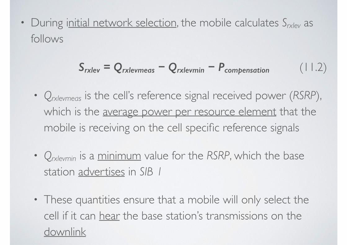
• During initial network selection, the mobile calculates Srxlev as follows
Srxlev = Qrxlevmeas − Qrxlevmin − Pcompensation (11.2)
• Qrxlevmeas is the cell’s reference signal received power (RSRP), which is the average power per resource element that the mobile is receiving on the cell specific reference signals
• Qrxlevmin is a minimum value for the RSRP, which the base station advertises in SIB 1
• These quantities ensure that a mobile will only select the cell if it can hear the base station’s transmissions on the downlink
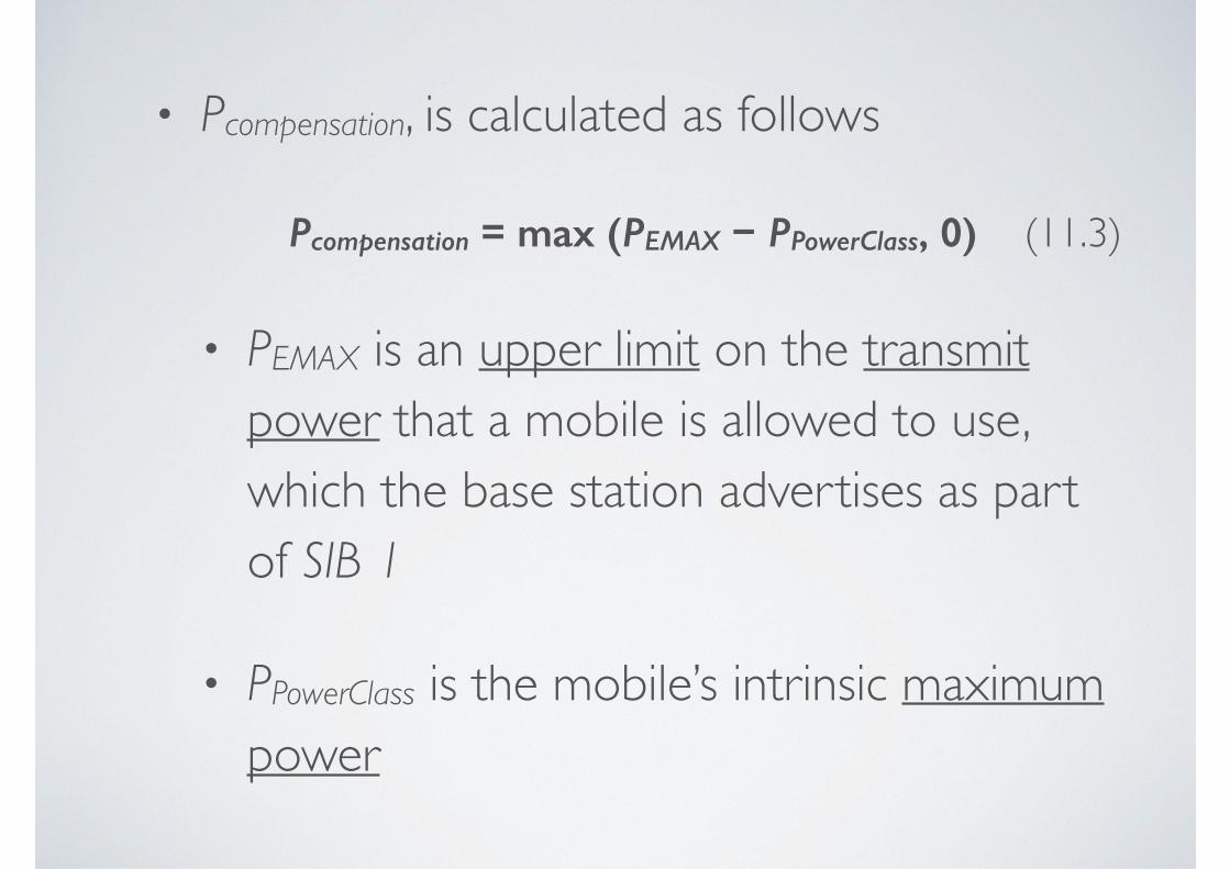
• Pcompensation, is calculated as follows
Pcompensation = max (PEMAX − PPowerClass, 0) (11.3)
• PEMAX is an upper limit on the transmit power that a mobile is allowed to use, which the base station advertises as part of SIB 1
• PPowerClass is the mobile’s intrinsic maximum power
• By combining these quantities, Pcompensation reduces the value of Srxlev if the mobile cannot reach the power limit that the base station is assuming
• It therefore ensures that a mobile will only select the cell if the base station can hear it on the uplink
Srxlev = Qrxlevmeas − Qrxlevmin − Pcompensation
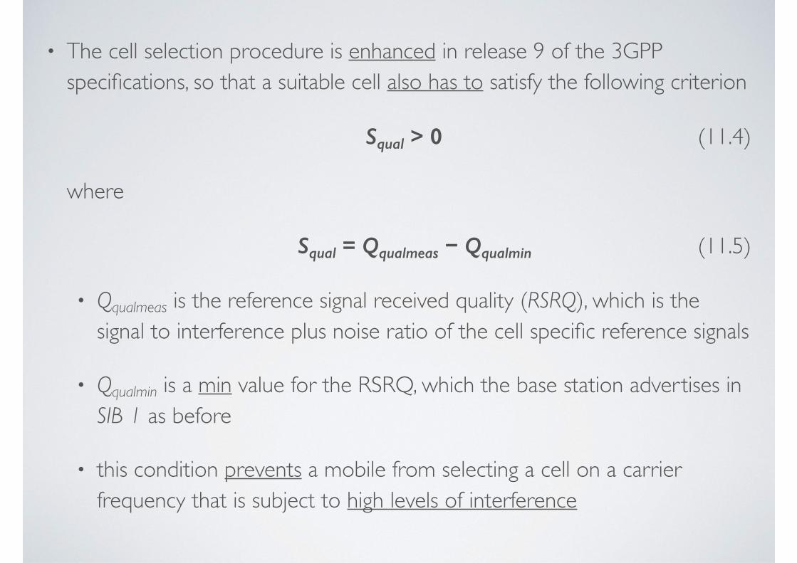
• The cell selection procedure is enhanced in release 9 of the 3GPP specifications, so that a suitable cell also has to satisfy the following criterion
Squal > 0 (11.4)
where
Squal = Qqualmeas − Qqualmin (11.5)
• Qqualmeas is the reference signal received quality (RSRQ), which is the signal to interference plus noise ratio of the cell specific reference signals
• Qqualmin is a min value for the RSRQ, which the base station advertises in SIB 1 as before
• this condition prevents a mobile from selecting a cell on a carrier frequency that is subject to high levels of interference
• A suitable cell must also satisfy a number of other criteria
• if the USIM contains a list of closed subscriber groups, then the cell has to meet the criteria for automatic or manual CSG selection that we defined above
• if the USIM does not, then the cell must lie outside any closed subscriber groups
• in addition, the network operator can bar a cell to all users or reserve it for operator use, by means of flags in SIB 1
3. RRC CONNECTION ESTABLISHMENT
• 3.1 Basic Procedure
• 3.2 Relationship with Other Procedures
3.1 BASIC PROCEDURE• Once the mobile has selected a network and a
cell to camp on, it runs the contention based random access procedure
• In doing so, it obtains a C-RNTI, an initial value for the timing advance and resources on the physical uplink shared channel (PUSCH) through which it can send a message to the network
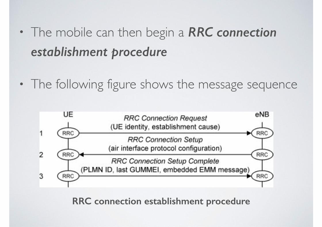
• The mobile can then begin a RRC connection establishment procedure
• The following figure shows the message sequence
RRC connection establishment procedure
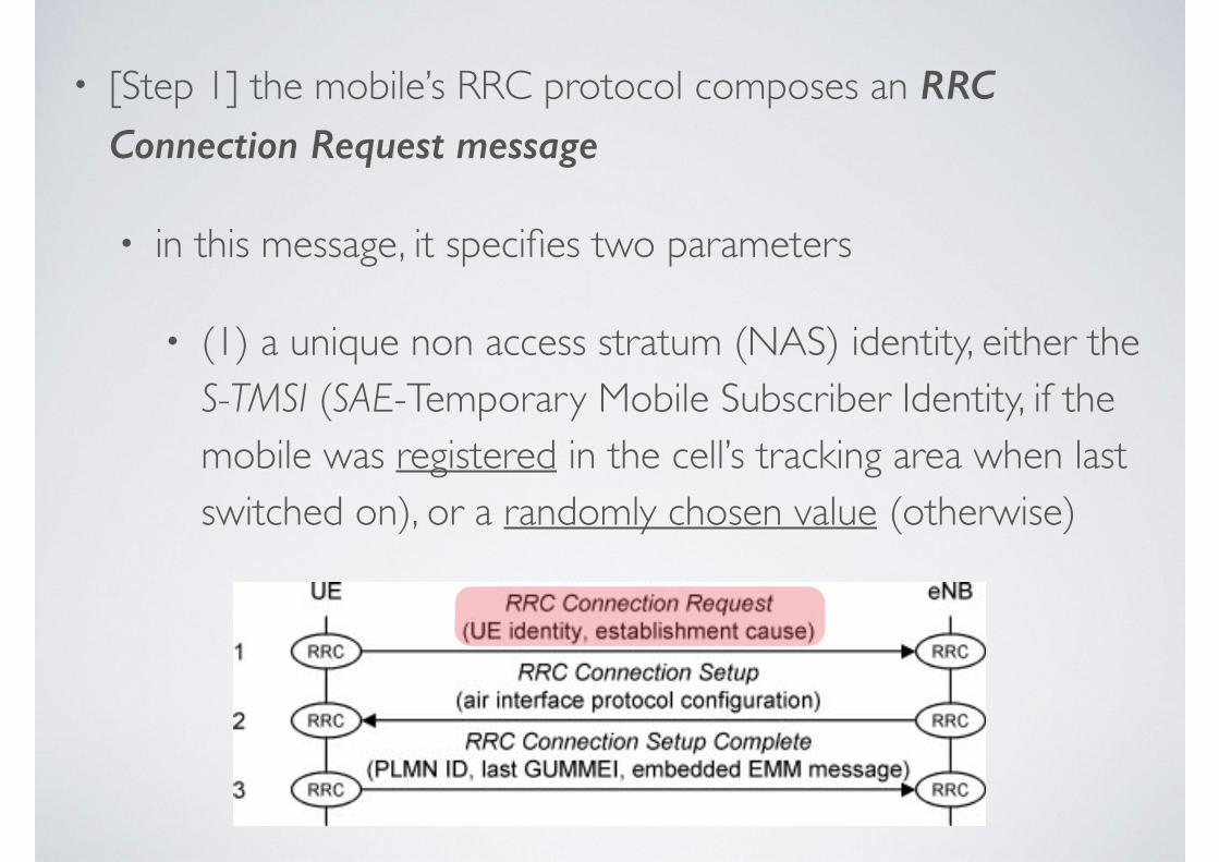
• [Step 1] the mobile’s RRC protocol composes an RRC Connection Request message
• in this message, it specifies two parameters
• (1) a unique non access stratum (NAS) identity, either the S-TMSI (SAE-Temporary Mobile Subscriber Identity, if the mobile was registered in the cell’s tracking area when last switched on), or a randomly chosen value (otherwise)
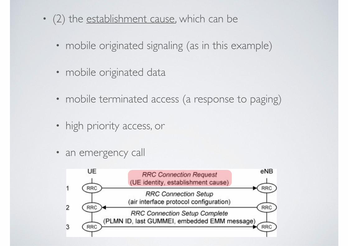
• (2) the establishment cause, which can be
• mobile originated signaling (as in this example)
• mobile originated data
• mobile terminated access (a response to paging)
• high priority access, or
• an emergency call
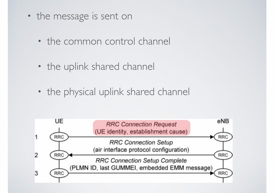
• the message is sent on
• the common control channel
• the uplink shared channel
• the physical uplink shared channel
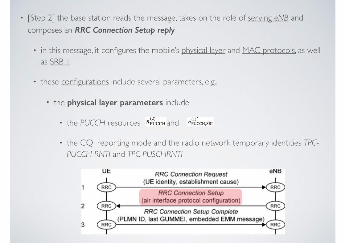
• [Step 2] the base station reads the message, takes on the role of serving eNB and composes an RRC Connection Setup reply
• in this message, it configures the mobile’s physical layer and MAC protocols, as well as SRB 1
• these configurations include several parameters, e.g.,
• the physical layer parameters include
• the PUCCH resources and
• the CQI reporting mode and the radio network temporary identities TPC-PUCCH-RNTI and TPC-PUSCHRNTI
• the MAC layer parameters include
• the time alignment timer
• the timer for periodic buffer status reports
• the max number of hybrid ARQ transmissions on the uplink
• the SRB 1 parameters include
• the priorities and prioritized bit rates of the corresponding logical channels
• the parameters that govern polling and status reporting in the RLC
• to reduce the size of the message, the base station can set several parameters to default values that are defined in the specifications
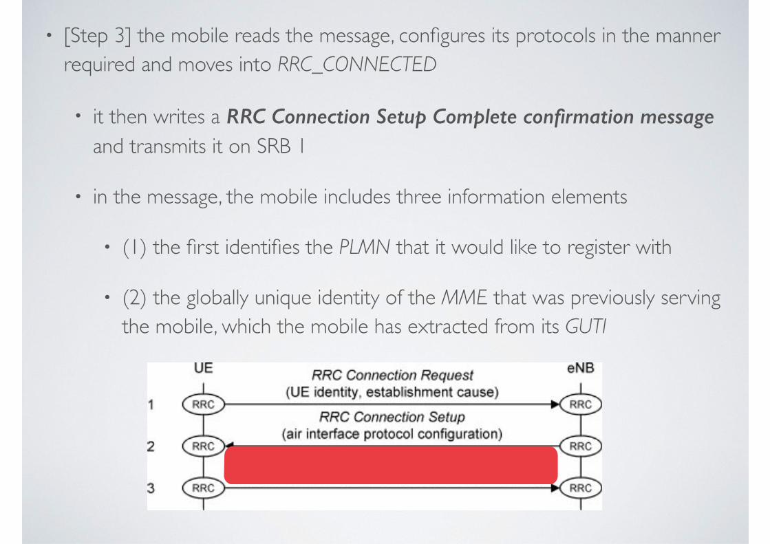
• [Step 3] the mobile reads the message, configures its protocols in the manner required and moves into RRC_CONNECTED
• it then writes a RRC Connection Setup Complete confirmation message and transmits it on SRB 1
• in the message, the mobile includes three information elements
• (1) the first identifies the PLMN that it would like to register with
• (2) the globally unique identity of the MME that was previously serving the mobile, which the mobile has extracted from its GUTI
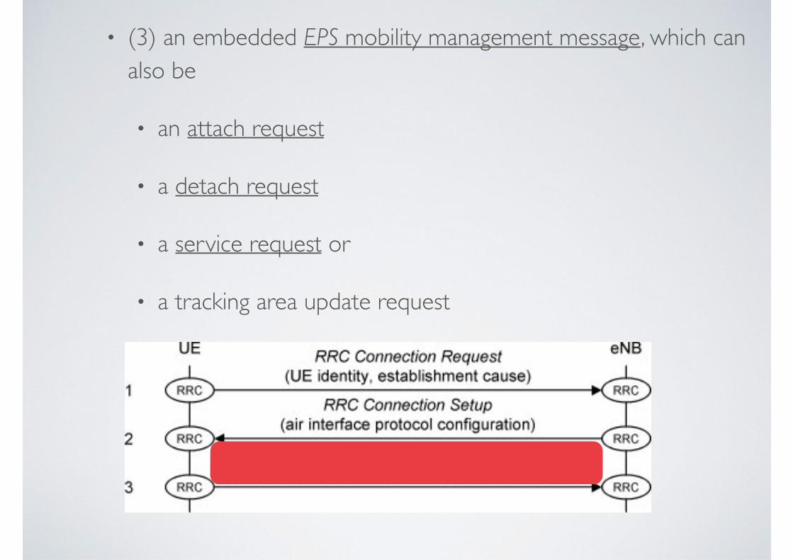
• (3) an embedded EPS mobility management message, which can also be
• an attach request
• a detach request
• a service request or
• a tracking area update request
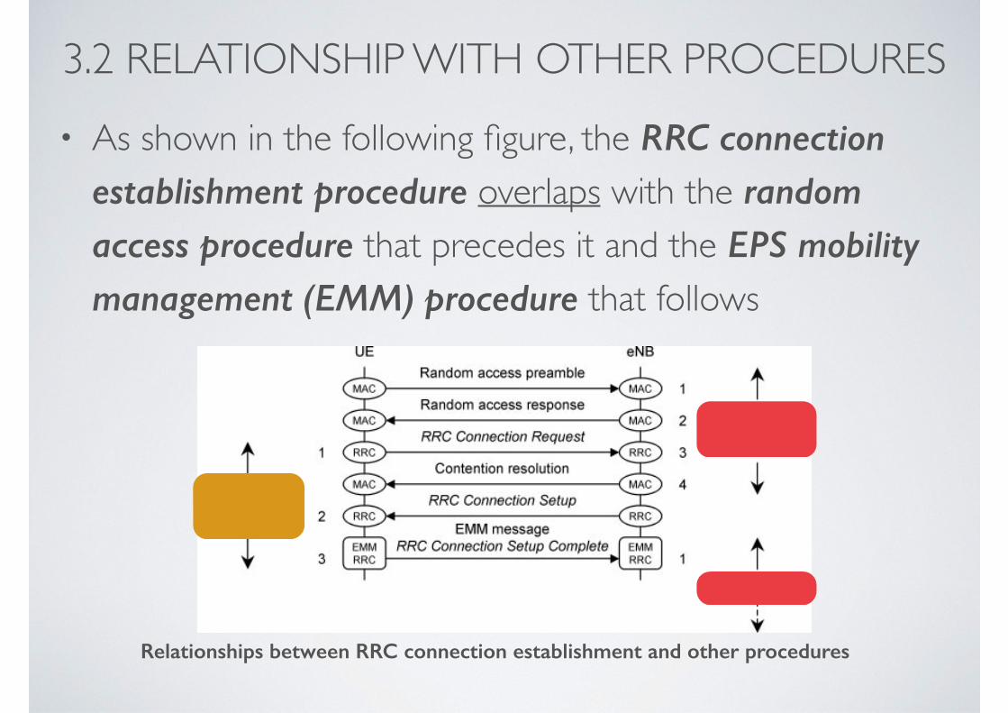
3.2 RELATIONSHIP WITH OTHER PROCEDURES• As shown in the following figure, the RRC connection
establishment procedure overlaps with the random access procedure that precedes it and the EPS mobility management (EMM) procedure that follows
Relationships between RRC connection establishment and other procedures
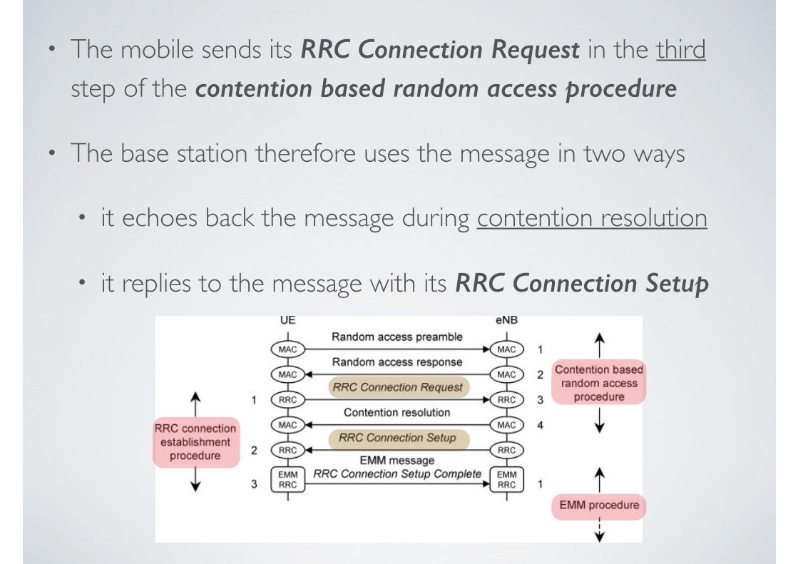
• The mobile sends its RRC Connection Request in the third step of the contention based random access procedure
• The base station therefore uses the message in two ways
• it echoes back the message during contention resolution
• it replies to the message with its RRC Connection Setup
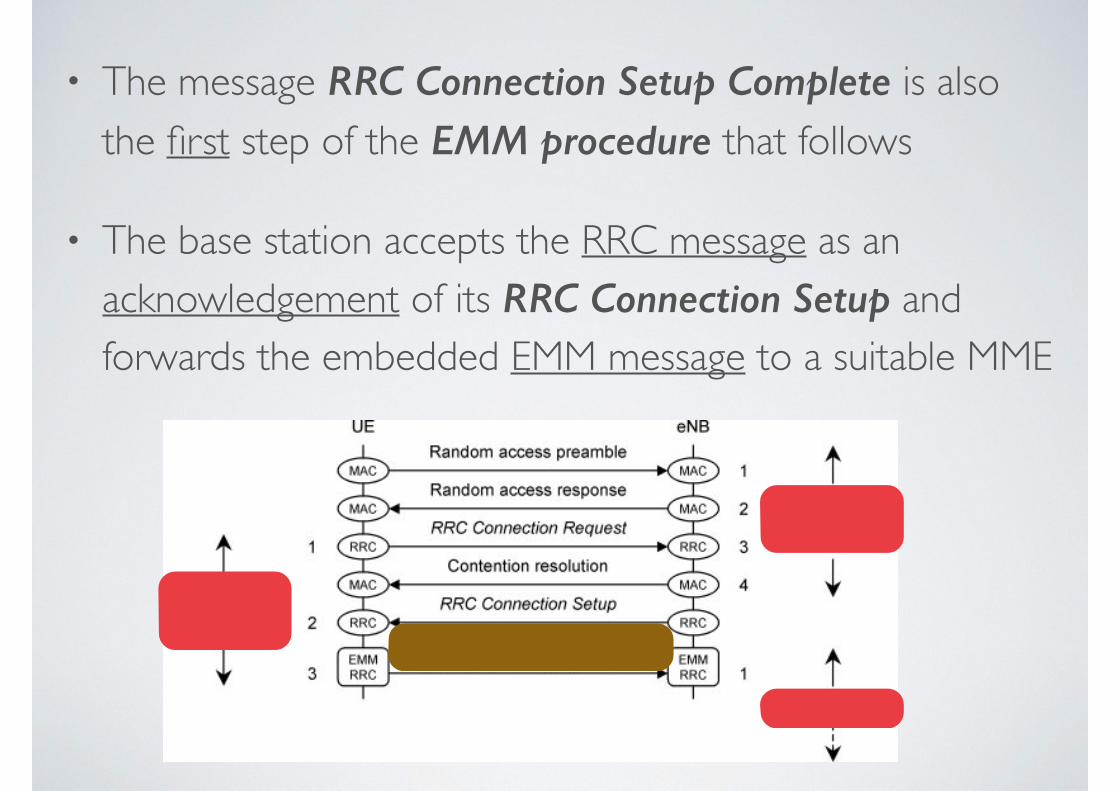
• The message RRC Connection Setup Complete is also the first step of the EMM procedure that follows
• The base station accepts the RRC message as an acknowledgement of its RRC Connection Setup and forwards the embedded EMM message to a suitable MME
4. ATTACH PROCEDURE4.1 IP Address Allocation
4.2 Overview of the Attach Procedure
4.3 Attach Request
4.4 Identification and Security Procedures
4.5 Location Update
4.6 Default Bearer Creation
4.7 Attach Accept
4.8 Default Bearer Update
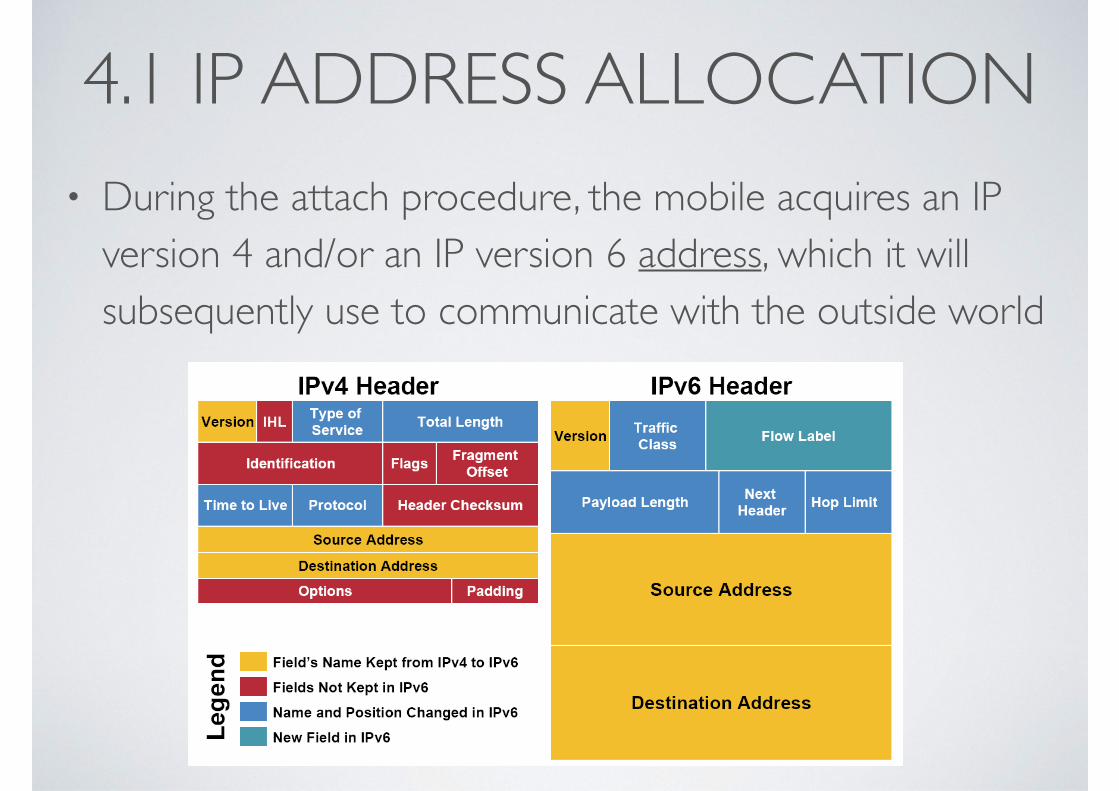
4.1 IP ADDRESS ALLOCATION• During the attach procedure, the mobile acquires an IP
version 4 and/or an IP version 6 address, which it will subsequently use to communicate with the outside world
• IPv4 addresses are 32 bits long
• in the usual technique, the PDN gateway allocates a dynamic IPv4 address to the mobile as part of the attach procedure
• it can either allocate the IP address by itself, or acquire a suitable IP address from a dynamic host configuration protocol version 4 (DHCPv4) server
• as an alternative, the mobile can itself use DHCPv4 to acquire a dynamic IP address after the attach procedure has completed
• to do this, it contacts the PDN gateway over the user plane, with the PDN gateway acting as a DHCPv4 server towards the mobile
• as before, the PDN gateway can obtain a suitable IP address from elsewhere, by acting as a DHCPv4 client towards another DHCPv4 server
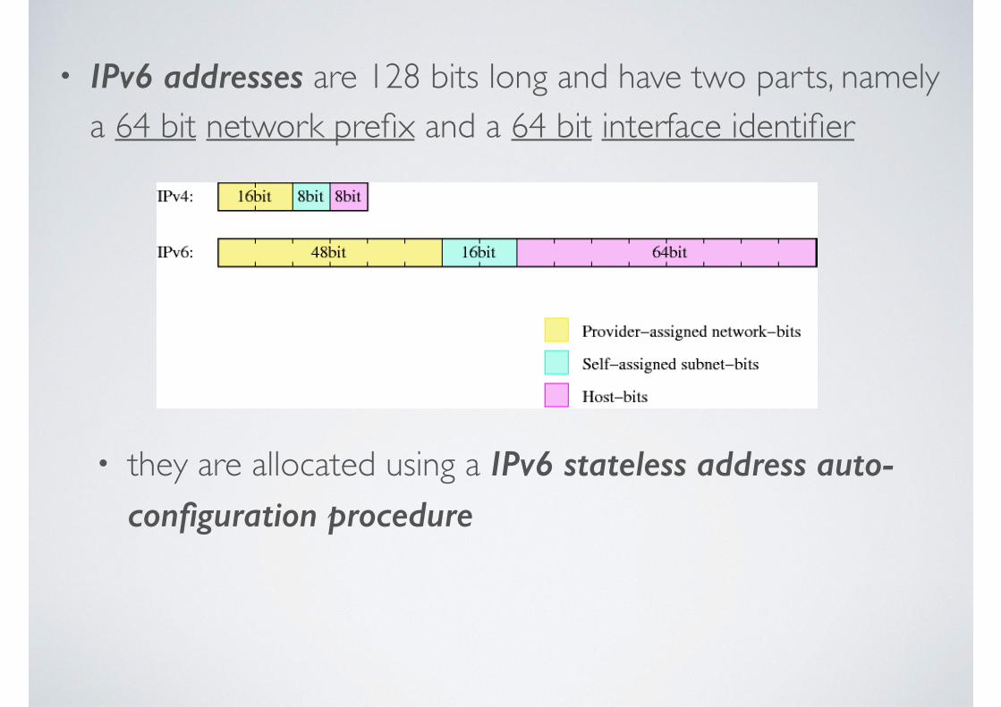
• IPv6 addresses are 128 bits long and have two parts, namely a 64 bit network prefix and a 64 bit interface identifier
• they are allocated using a IPv6 stateless address auto-configuration procedure
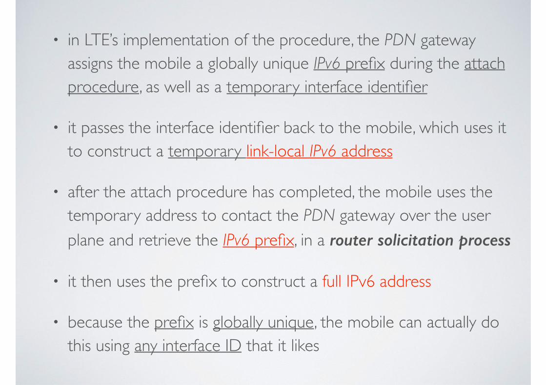
• in LTE’s implementation of the procedure, the PDN gateway assigns the mobile a globally unique IPv6 prefix during the attach procedure, as well as a temporary interface identifier
• it passes the interface identifier back to the mobile, which uses it to construct a temporary link-local IPv6 address
• after the attach procedure has completed, the mobile uses the temporary address to contact the PDN gateway over the user plane and retrieve the IPv6 prefix, in a router solicitation process
• it then uses the prefix to construct a full IPv6 address
• because the prefix is globally unique, the mobile can actually do this using any interface ID that it likes

• A mobile can also use a static IPv4 address or IPv6 prefix
• The mobile does not store these permanently, however: instead, the network stores them in the home subscriber server or a DHCP server and sends them to the mobile during the attach procedure
• Subsequently, the mobile will use the same IP address for any dedicated bearers that it sets up with the same packet data network
• If it establishes communications with another packet data network, then it will acquire another IP address using the same technique
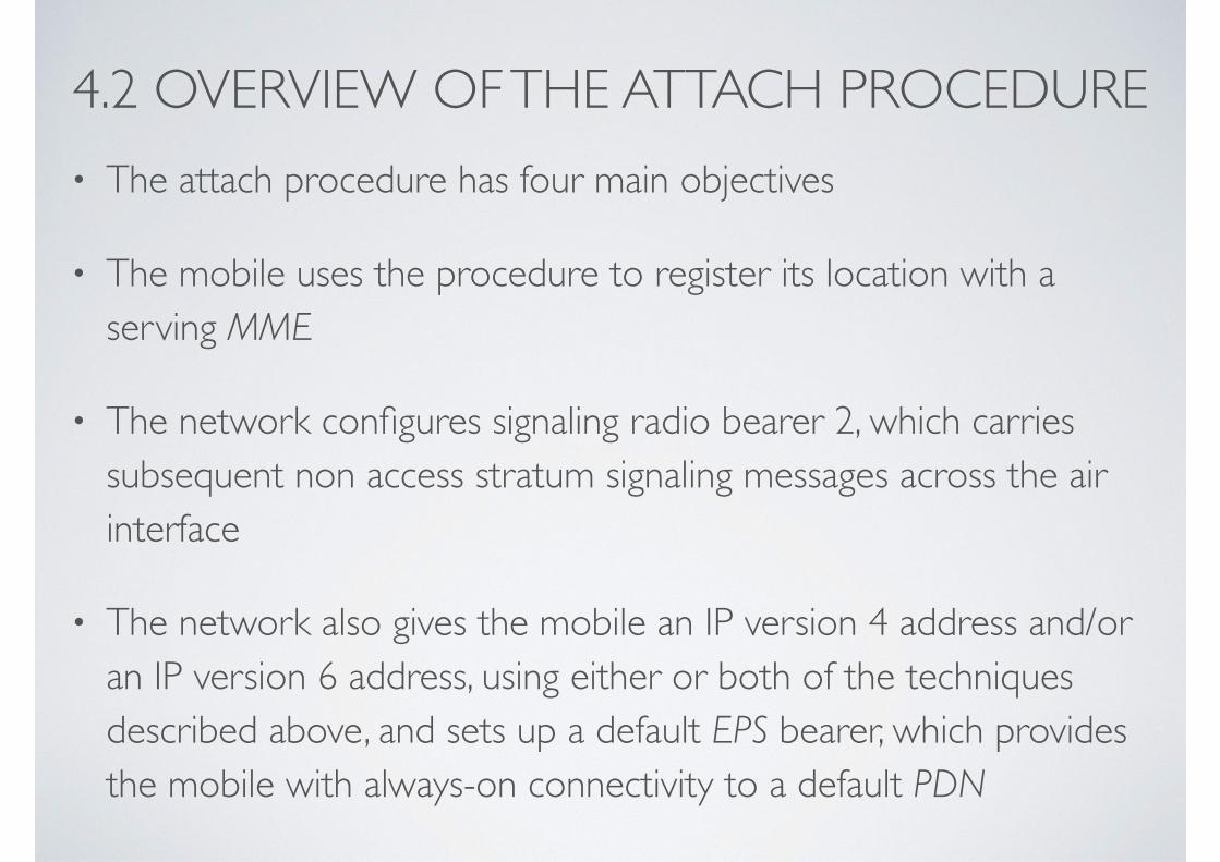
4.2 OVERVIEW OF THE ATTACH PROCEDURE• The attach procedure has four main objectives
• The mobile uses the procedure to register its location with a serving MME
• The network configures signaling radio bearer 2, which carries subsequent non access stratum signaling messages across the air interface
• The network also gives the mobile an IP version 4 address and/or an IP version 6 address, using either or both of the techniques described above, and sets up a default EPS bearer, which provides the mobile with always-on connectivity to a default PDN
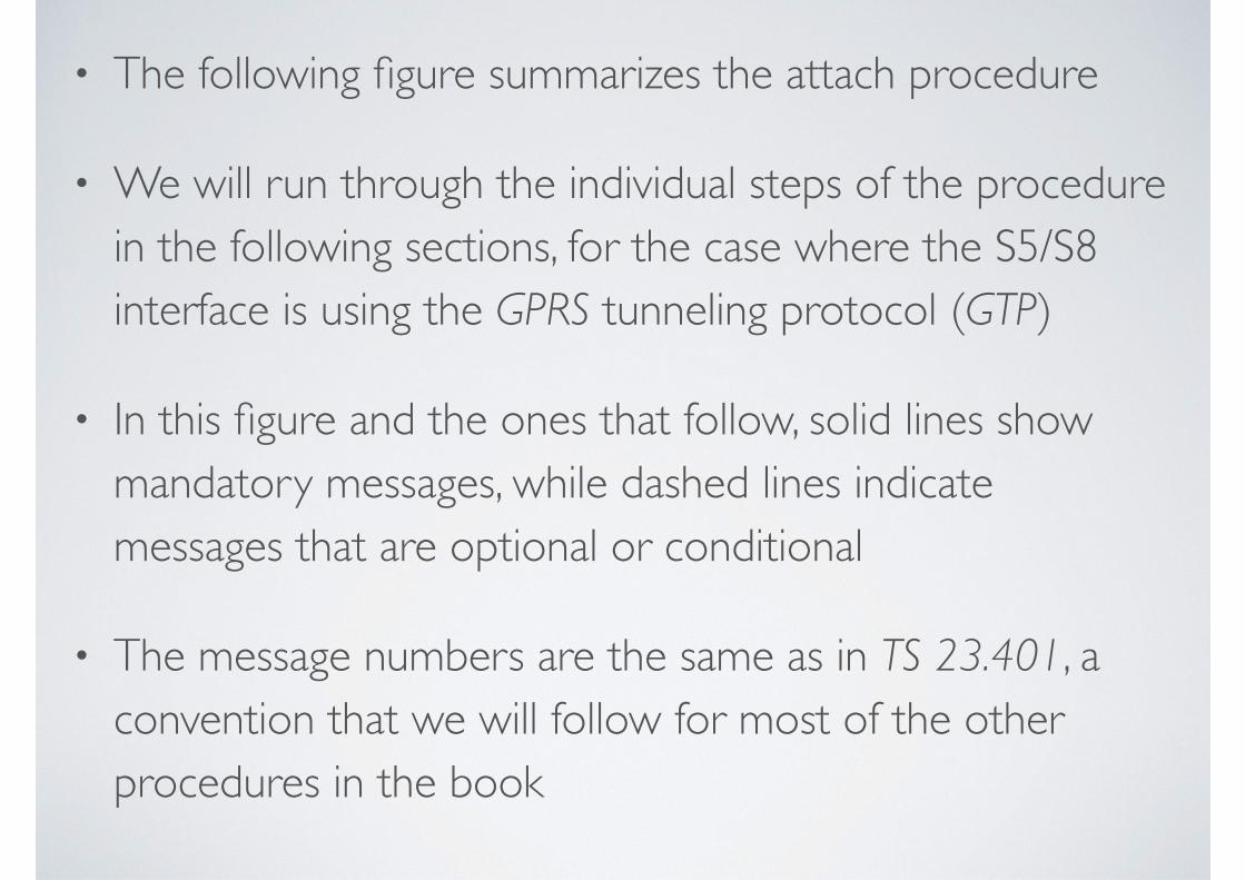
• The following figure summarizes the attach procedure
• We will run through the individual steps of the procedure in the following sections, for the case where the S5/S8 interface is using the GPRS tunneling protocol (GTP)
• In this figure and the ones that follow, solid lines show mandatory messages, while dashed lines indicate messages that are optional or conditional
• The message numbers are the same as in TS 23.401, a convention that we will follow for most of the other procedures in the book
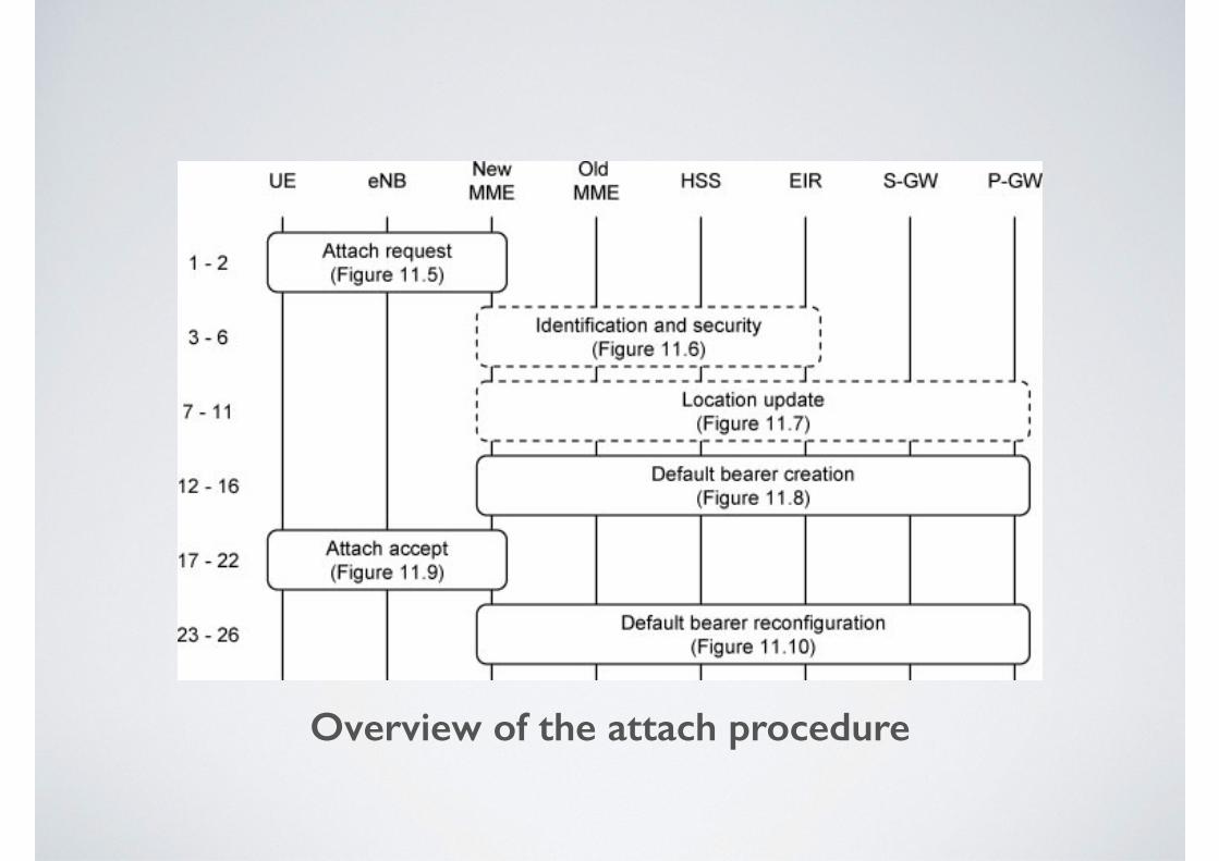
Overview of the attach procedure
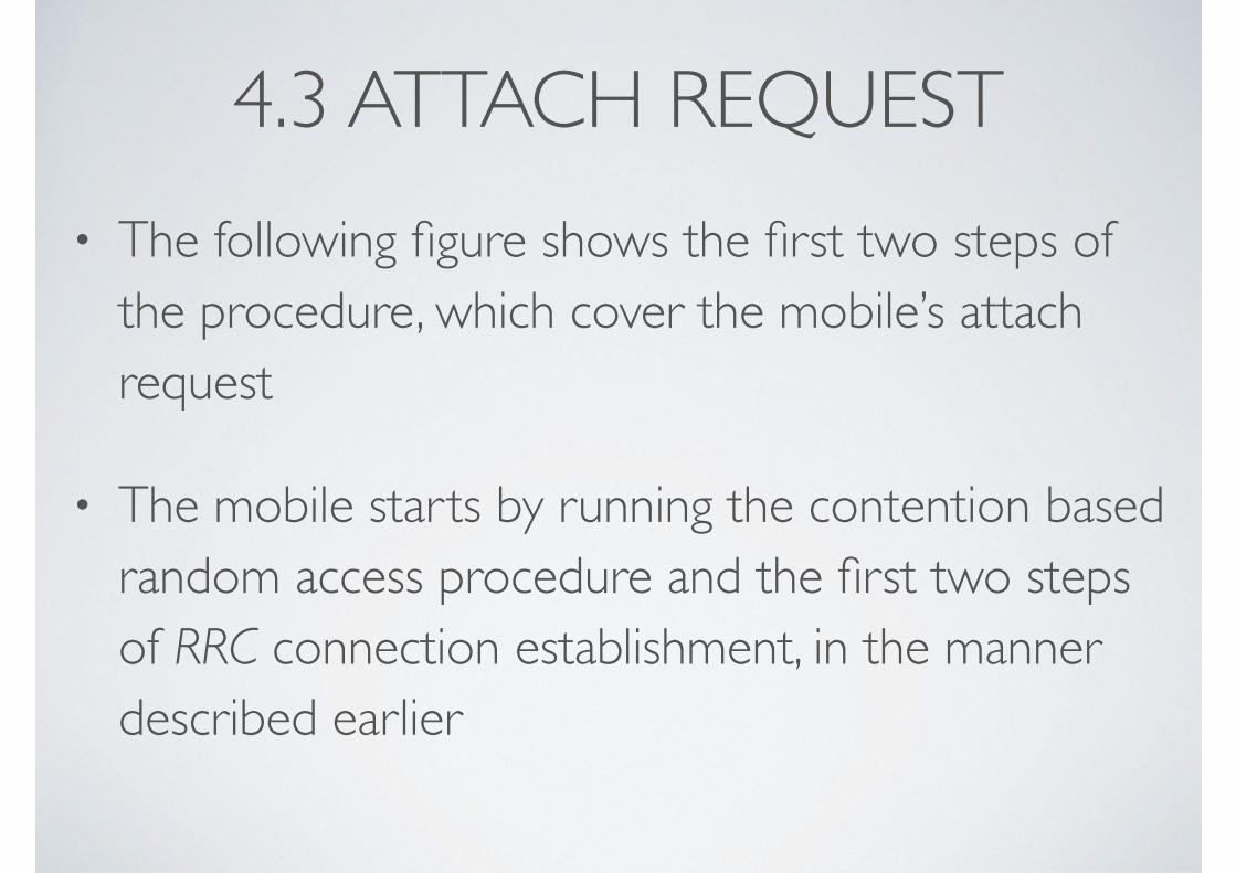
4.3 ATTACH REQUEST• The following figure shows the first two steps of
the procedure, which cover the mobile’s attach request
• The mobile starts by running the contention based random access procedure and the first two steps of RRC connection establishment, in the manner described earlier
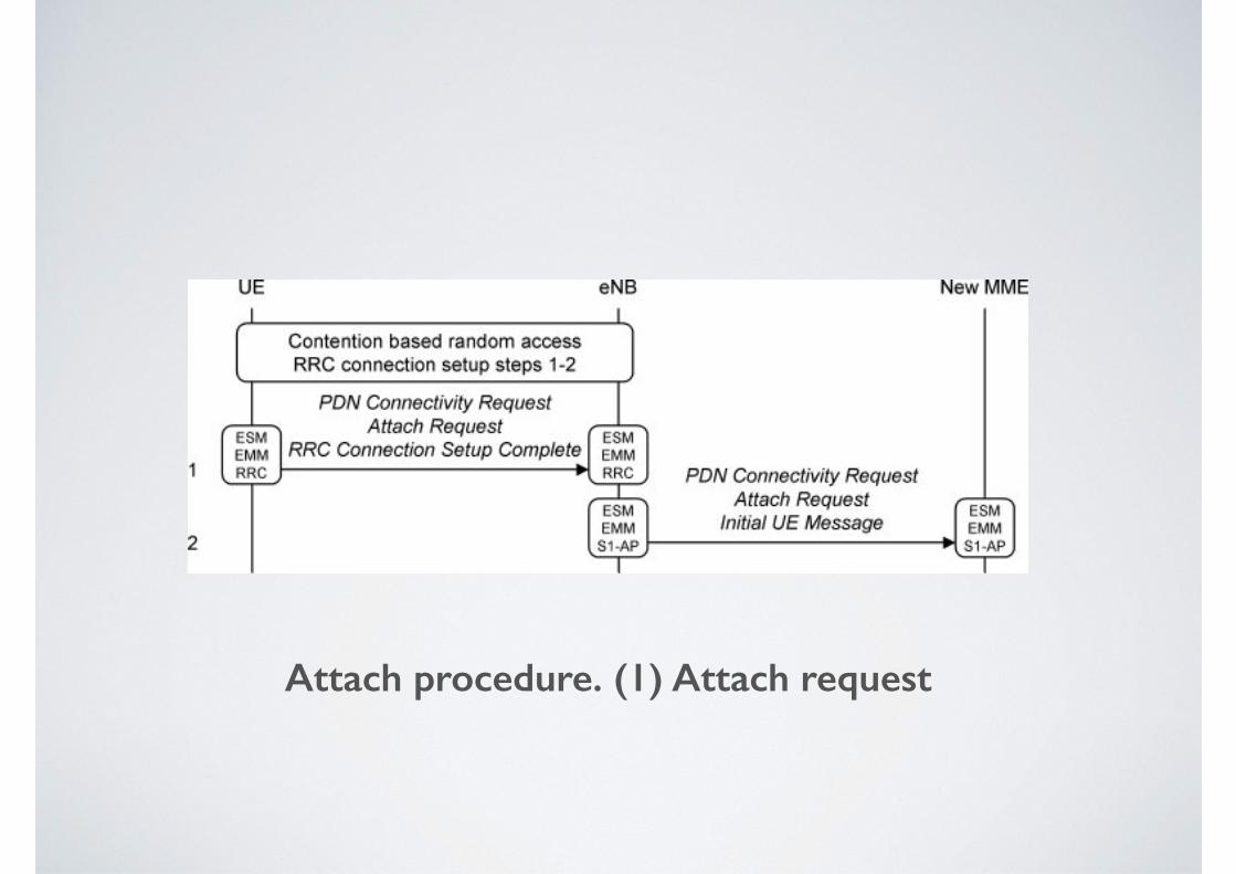
Attach procedure. (1) Attach request
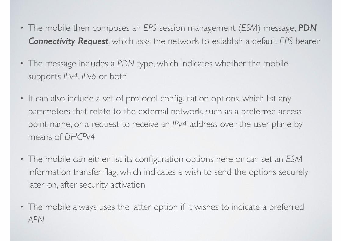
• The mobile then composes an EPS session management (ESM) message, PDN Connectivity Request, which asks the network to establish a default EPS bearer
• The message includes a PDN type, which indicates whether the mobile supports IPv4, IPv6 or both
• It can also include a set of protocol configuration options, which list any parameters that relate to the external network, such as a preferred access point name, or a request to receive an IPv4 address over the user plane by means of DHCPv4
• The mobile can either list its configuration options here or can set an ESM information transfer flag, which indicates a wish to send the options securely later on, after security activation
• The mobile always uses the latter option if it wishes to indicate a preferred APN
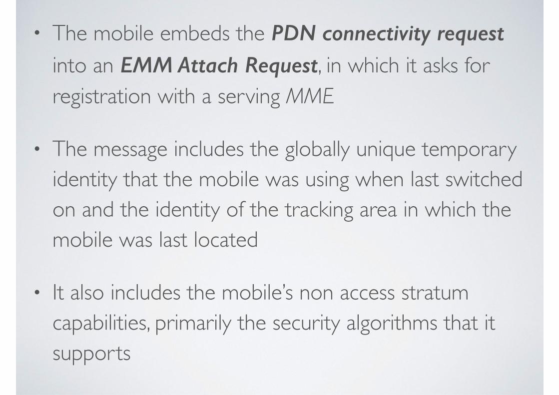
• The mobile embeds the PDN connectivity request into an EMM Attach Request, in which it asks for registration with a serving MME
• The message includes the globally unique temporary identity that the mobile was using when last switched on and the identity of the tracking area in which the mobile was last located
• It also includes the mobile’s non access stratum capabilities, primarily the security algorithms that it supports
• In turn, the mobile embeds the Attach Request into the last message from the RRC connection establishment procedure, RRC Connection Setup Complete
• As noted earlier, the RRC message also identifies the PLMN that the mobile would like to register with and the identity of its last serving MME
• In step 1 of the attach procedure, the mobile sends this message to the serving eNB
• As described in Chapter 12, the mobile and MME can store their LTE security keys after the mobile switches off
• If the mobile has a valid set of security keys, then it uses these to secure the attach request using a process known as integrity protection
• This assures the MME that the request is coming from a genuine mobile, and not from an intruder
• The base station extracts the EMM and ESM messages and embeds them into an S1-AP Initial UE Message, which requests the establishment of an S1 signaling connection for the mobile
• As part of this message, the base station specifies the RRC establishment cause and the requested PLMN, which it received from the mobile during the RRC procedure
• The base station can now forward the message to a suitable MME (step 2)
• Usually, the chosen MME is the same one that the mobile was previously registered with
• This can be done if two conditions are met: the base station has to lie in one of the old MME’s pool areas and the old MME has to lie in the requested PLMN
• If the mobile has changed pool area since it was last switched on, or if it is asking to register with a different network, then the base station selects another MME
• It does so by choosing at random from the ones in its pool area, according to a load balancing algorithm
4.4 IDENTIFICATION AND SECURITY PROCEDURES
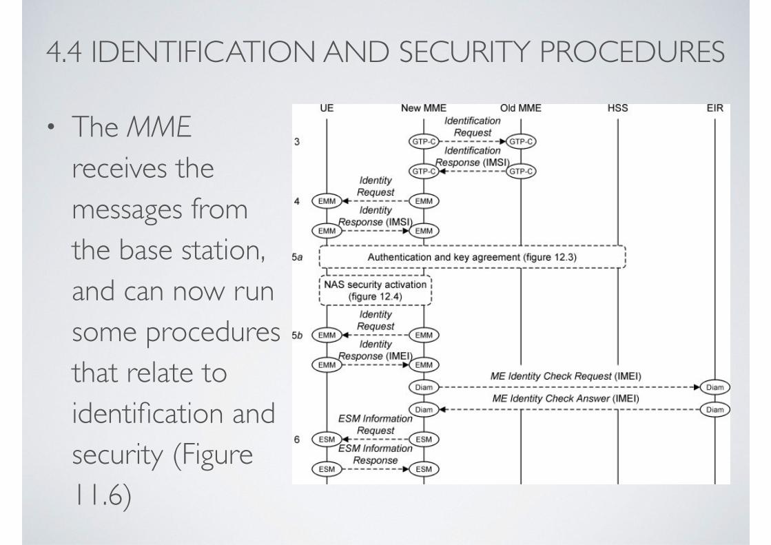
• The MME receives the messages from the base station, and can now run some procedures that relate to identification and security (Figure 11.6)
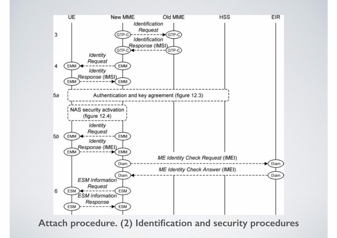
Attach procedure. (2) Identification and security procedures
• If the mobile has moved to a new MME since it was last switched on, then the MME has to find out the mobile’s identity
• To do this, it extracts the identity of the old MME from the mobile’s GUTI and sends the GUTI to the old MME in a GTP-C Identification Request (3)
• The old MME’s response includes the international mobile subscriber identity (IMSI) and the mobile’s security keys
• In exceptional cases, however, the mobile may be unknown to the old MME
• If this happens, then the new MME asks the mobile for its IMSI using an EMM Identity Request (4), a message that is transported using the NAS information transfer procedure from Chapter 2
• The network can now run two security procedures (5a)
• In authentication and key agreement, the mobile and network confirm each other’s identities and set up a new set of security keys
• In NAS security activation, the MME activates those keys and initiates the secure protection of all subsequent EMM and ESM messages
• These steps are mandatory if there was any problem with the integrity protection of the attach request, and are optional otherwise
• If the integrity check succeeded, then the MME can implicitly re-activate the mobile’s old keys by sending it a signaling message that it has secured using those keys, thus skipping both of these procedures
• The MME then retrieves the international mobile equipment identity (IMEI) (5b)
• It can combine this message with NAS security activation to reduce the amount of signaling, but it is mandatory for the MME to retrieve the IMEI somehow
• As a protection against stolen mobiles, the MME can optionally send the IMEI to the equipment identity register, which responds by either accepting or rejecting the device
• If the mobile set the ESM information transfer flag in its PDN Connectivity Request, then the MME can now send it an ESM Information Request (6)
• The mobile sends its protocol configuration options in response
• Now that the network has activated NAS security, the mobile can send the message securely
4.5 LOCATION UPDATE• The MME can now update the network’s record of the
mobile’s location (Figure 11.7)
• If the mobile is re-attaching to its previous MME without having properly detached (for example, if its battery ran out), then the MME may still have some EPS bearers that are associated with the mobile
• If this is the case then the MME deletes them (7), by following steps from the detach procedure that we will see later on
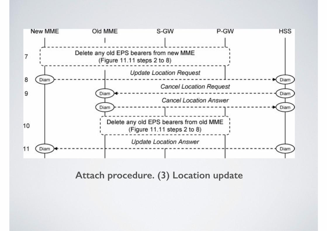
Attach procedure. (3) Location update
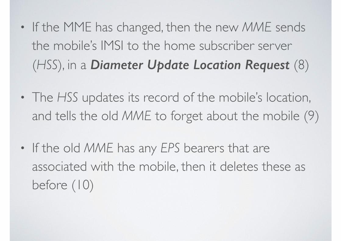
• If the MME has changed, then the new MME sends the mobile’s IMSI to the home subscriber server (HSS), in a Diameter Update Location Request (8)
• The HSS updates its record of the mobile’s location, and tells the old MME to forget about the mobile (9)
• If the old MME has any EPS bearers that are associated with the mobile, then it deletes these as before (10)
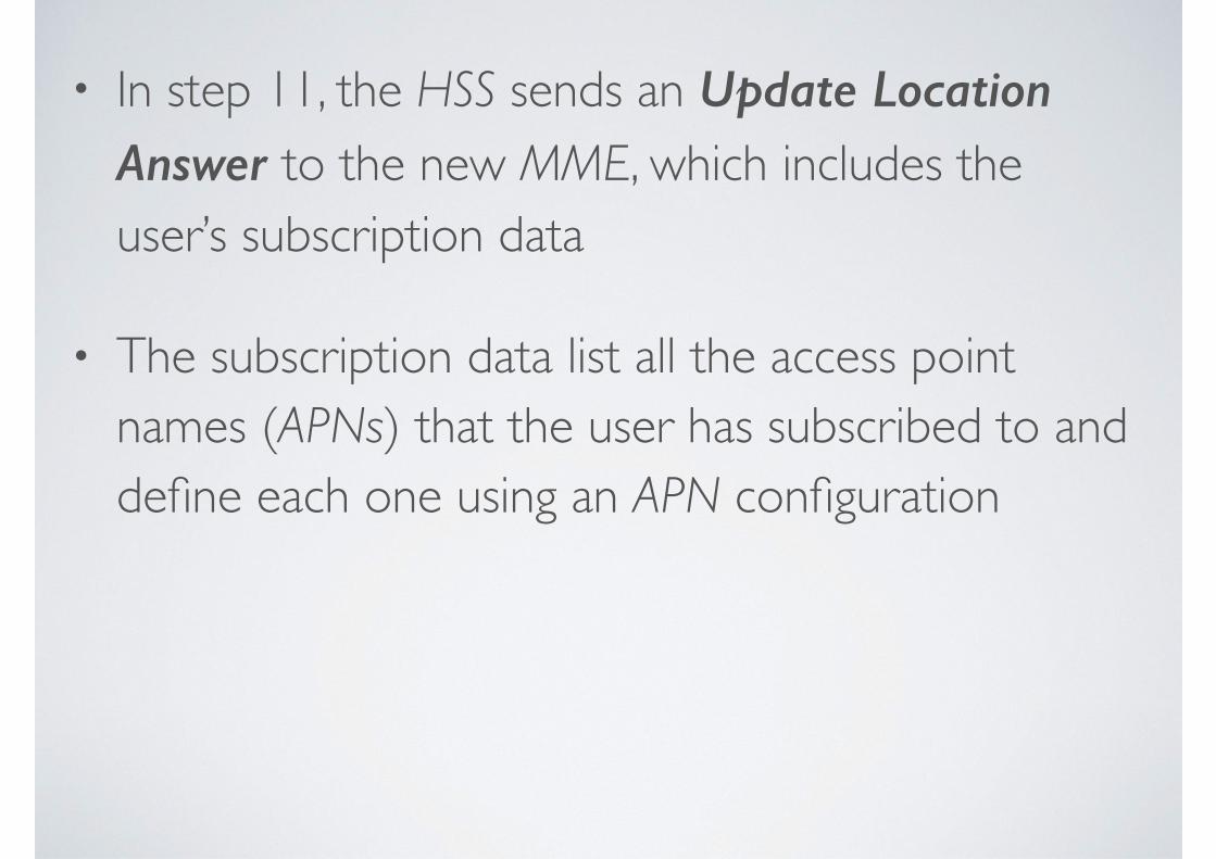
• In step 11, the HSS sends an Update Location Answer to the new MME, which includes the user’s subscription data
• The subscription data list all the access point names (APNs) that the user has subscribed to and define each one using an APN configuration
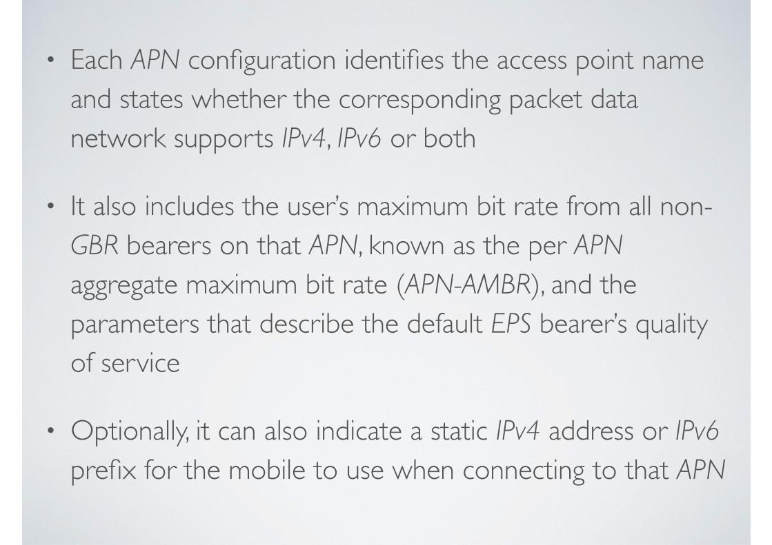
• Each APN configuration identifies the access point name and states whether the corresponding packet data network supports IPv4, IPv6 or both
• It also includes the user’s maximum bit rate from all non-GBR bearers on that APN, known as the per APN aggregate maximum bit rate (APN-AMBR), and the parameters that describe the default EPS bearer’s quality of service
• Optionally, it can also indicate a static IPv4 address or IPv6 prefix for the mobile to use when connecting to that APN
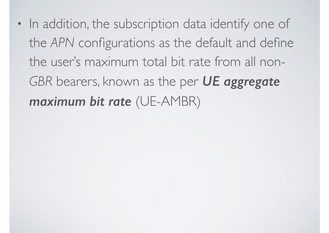
• In addition, the subscription data identify one of the APN configurations as the default and define the user’s maximum total bit rate from all non-GBR bearers, known as the per UE aggregate maximum bit rate (UE-AMBR)
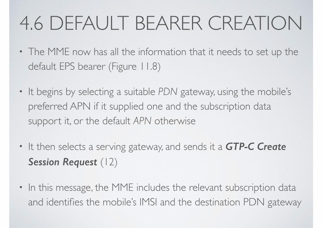
4.6 DEFAULT BEARER CREATION• The MME now has all the information that it needs to set up the
default EPS bearer (Figure 11.8)
• It begins by selecting a suitable PDN gateway, using the mobile’s preferred APN if it supplied one and the subscription data support it, or the default APN otherwise
• It then selects a serving gateway, and sends it a GTP-C Create Session Request (12)
• In this message, the MME includes the relevant subscription data and identifies the mobile’s IMSI and the destination PDN gateway
Attach procedure. (4) Default bearer creation
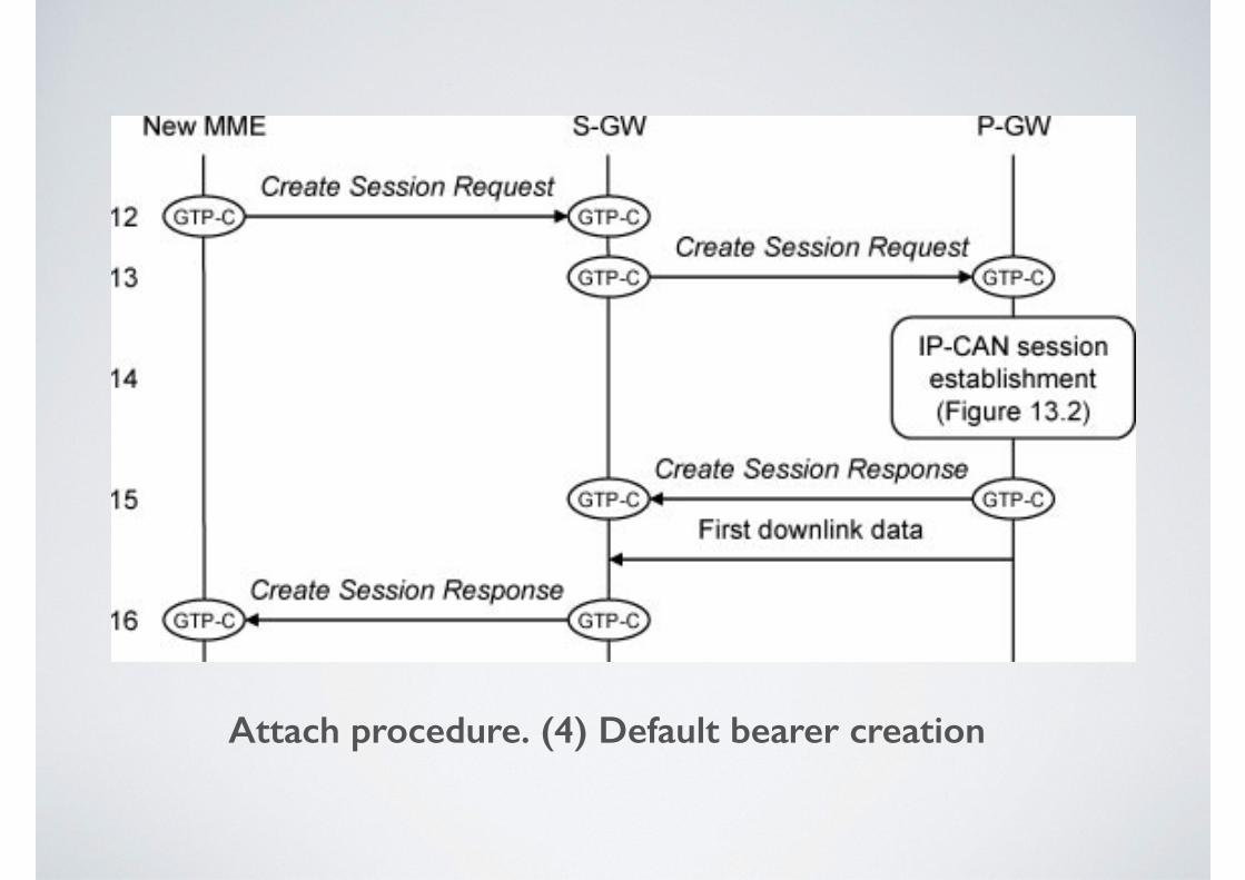
• The serving gateway receives the message and forwards it to the PDN gateway (13)
• In the message, the serving gateway includes a GTP-U tunnel endpoint identifier (TEID), which the PDN gateway will eventually use to send it downlink packets across the S5/S8 interface
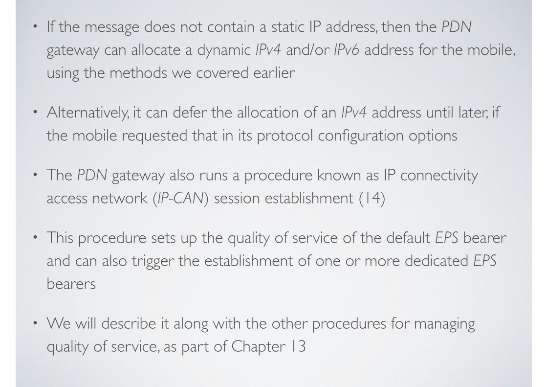
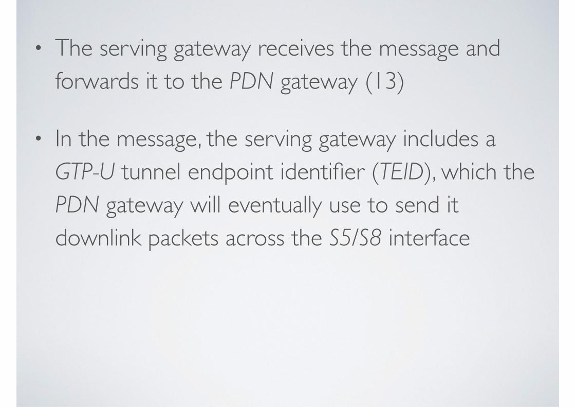
• If the message does not contain a static IP address, then the PDN gateway can allocate a dynamic IPv4 and/or IPv6 address for the mobile, using the methods we covered earlier
• Alternatively, it can defer the allocation of an IPv4 address until later, if the mobile requested that in its protocol configuration options
• The PDN gateway also runs a procedure known as IP connectivity access network (IP-CAN) session establishment (14)
• This procedure sets up the quality of service of the default EPS bearer and can also trigger the establishment of one or more dedicated EPS bearers
• We will describe it along with the other procedures for managing quality of service, as part of Chapter 13
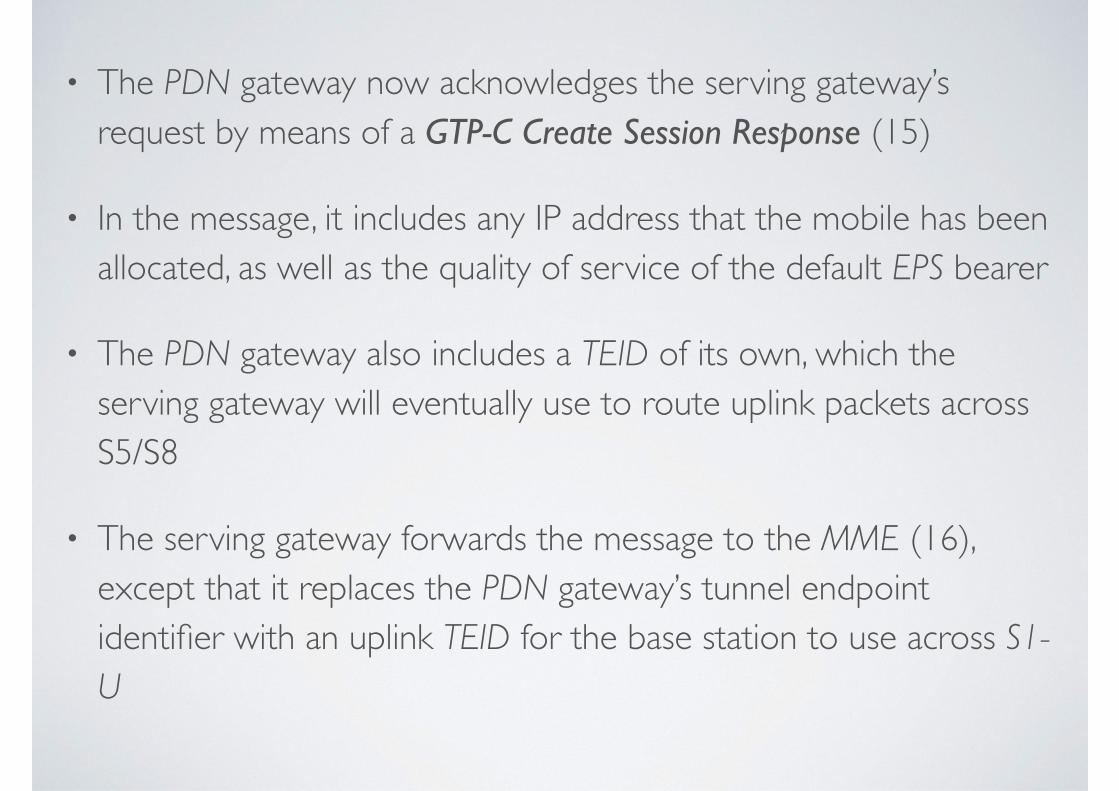
• The PDN gateway now acknowledges the serving gateway’s request by means of a GTP-C Create Session Response (15)
• In the message, it includes any IP address that the mobile has been allocated, as well as the quality of service of the default EPS bearer
• The PDN gateway also includes a TEID of its own, which the serving gateway will eventually use to route uplink packets across S5/S8
• The serving gateway forwards the message to the MME (16), except that it replaces the PDN gateway’s tunnel endpoint identifier with an uplink TEID for the base station to use across S1-U
4.7 ATTACH ACCEPT• The MME can now reply to the mobile’s attach request, as
shown in the following figure
• It first initiates an ESM procedure known as Default EPS bearer context activation, which is a response to the mobile’s PDN Connectivity Request and which starts with a Activate Default EPS Bearer Context Request message
• The message includes the EPS bearer identity, the access point name, the quality of service and any IP address that the network has allocated to the mobile
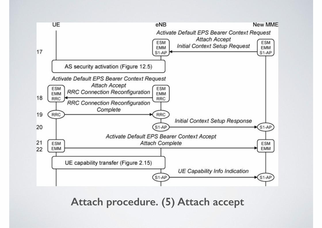
Attach procedure. (5) Attach accept
• The MME embeds the ESM message into an EMM Attach Accept, which is a response to the mobile’s original attach request
• The message includes a list of tracking areas in which the MME has registered the mobile and a new globally unique temporary identity
• In turn, the MME embeds both messages into an S1-AP Initial Context Setup Request
• This is the start of a procedure known as Initial context setup, which was triggered by the base station’s Initial UE Message
• The procedure tells the base station to set up an S1 signaling connection for the mobile, and S1 and radio bearers that correspond to the default EPS bearer
• The message includes the bearers’ quality of service, the uplink TEID that the MME received from the serving gateway and a key for the activation of access stratum security
• The MME sends all three messages to the base station, in step 17
• The base station now activates access stratum security, using the secure key that it has just received
• From this point, all the data and RRC signaling messages on the air interface are secured
• It then composes an RRC Connection Reconfiguration message, in which it modifies the mobile’s RRC connection so as to set up two new radio bearers: a radio bearer that will carry the default EPS bearer, and SRB 2
• It sends this message to the mobile, along with the EMM and ESM messages that it has just received from the MME (18)
• The mobile reconfigures its RRC connection as instructed and sets up the default EPS bearer
• It then sends its acknowledgements to the network in two stages. Using SRB 1, the mobile first sends the base station an acknowledgement known as RRC Connection Reconfiguration Complete, which triggers an S1-AP Initial Context Setup Response to the MME (20)
• The S1-AP message includes a downlink TEID for the serving gateway to use across S1-U
• The mobile then composes an ESM Activate Default EPS Bearer Context Accept and embeds it into an EMM Attach Complete, to acknowledge the ESM and EMM parts of message 18
• It sends these messages to the base station on SRB 2 (21), using the NAS information transfer procedure, and the base station forwards the messages to the MME (22)
• At about this point, the base station retrieves the mobile’s radio access capabilities, using the procedure we covered in Chapter 2
• It sends the capabilities back to the MME using an S1-AP UE Capability Info Indication, which stores them until the mobile detaches from the network
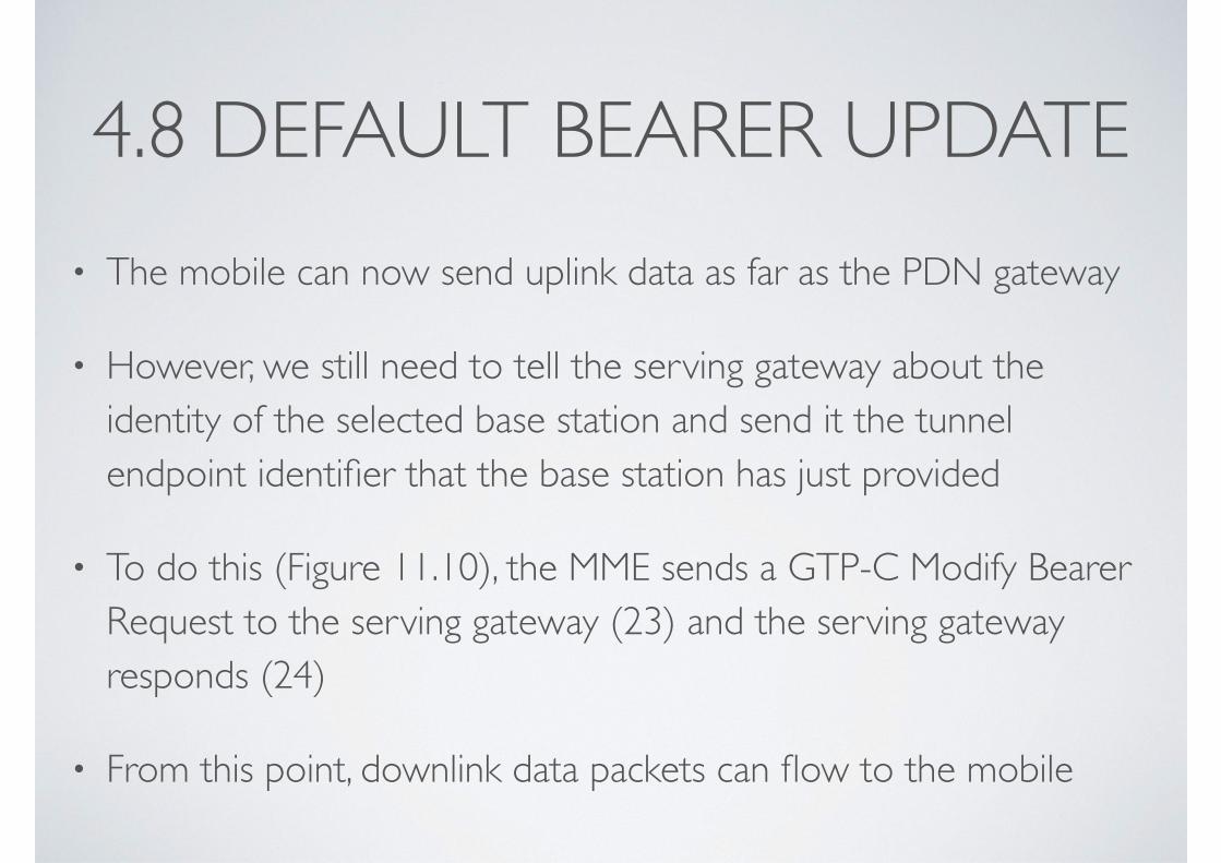
4.8 DEFAULT BEARER UPDATE• The mobile can now send uplink data as far as the PDN gateway
• However, we still need to tell the serving gateway about the identity of the selected base station and send it the tunnel endpoint identifier that the base station has just provided
• To do this (Figure 11.10), the MME sends a GTP-C Modify Bearer Request to the serving gateway (23) and the serving gateway responds (24)
• From this point, downlink data packets can flow to the mobile
Attach procedure. (6) Default bearer update
• The MME can also notify the HSS about the chosen PDN gateway and APN (25)
• It does this if the chosen PDN gateway is different from the one in the default APN configuration, for example, if the mobile requested an access point name of its own to connect to
• The HSS stores the chosen PDN gateway, for use in any future handovers to non 3GPP systems, and responds (26)
• Finally, the mobile may have to contact the PDN gateway across the user plane, to complete the allocation of its IP addresses
• It does this when obtaining an IPv6 prefix using stateless auto-configuration, and also when obtaining an IPv4 address using DHCPv4
• The mobile is now in the states EMM-REGISTERED, ECM-CONNECTED and RRC_CONNECTED and will stay in these states for as long as the user is actively communicating with the outside world
• If the user does nothing, the network can transfer the mobile into ECM-IDLE and RRC_IDLE using a procedure known as S1 release
• We will cover this procedure later, as part of Chapter 14
5. DETACH PROCEDURE
• The last process to consider in this chapter is the Detach procedure
• This cancels the mobile’s registration with the evolved packet core and is normally used when the mobile switches off, as shown in the following figure
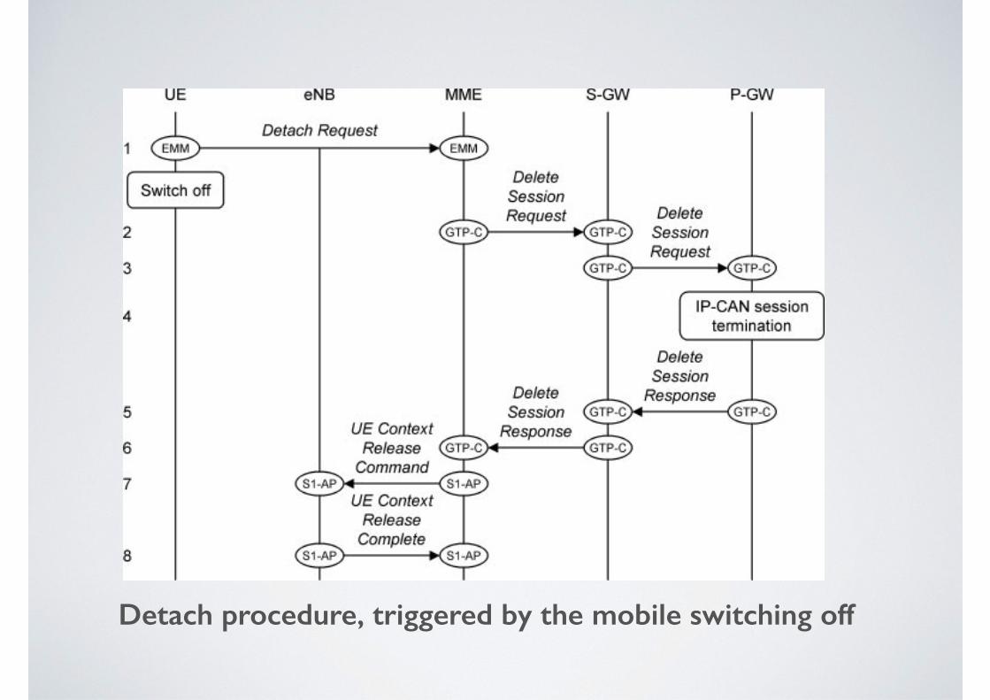
Detach procedure, triggered by the mobile switching off
• We will assume that the mobile starts in ECM-CONNECTED and RRC_CONNECTED, consistent with its state at the end of the previous section
• The user triggers the procedure by telling the mobile to shut down
• In response, the mobile composes an EMM Detach Request, in which it specifies its GUTI, and sends the message to the MME (1)
• After sending the message, the mobile can switch off without waiting for a reply
• The MME now has to tear down the mobile’s EPS bearers
• To do this, it looks up the mobile’s serving gateway and sends it a GTP-C Delete Session Request (2)
• The serving gateway forwards the message to the PDN gateway (3), which runs a procedure known as IP-CAN session termination (4) that undoes the earlier effect of IP-CAN session establishment
• The PDN gateway then tears down all the mobile’s bearers and replies to the serving gateway (5), which tears down its bearers in the same way and replies to the MME (6)
• If necessary, these steps are repeated for any other network that the mobile is connected to
• To finish the procedure, the MME tells the base station to tear down all the resources that are related to the mobile and indicates that the cause is a detach request (7)
• The base station does so and responds (8)
• The MME can now delete most of the information that it associated with the mobile
• However, it keeps a record of the mobile’s IMSI, GUTI and security keys, as it will need these next time the mobile switches on
• If the mobile starts in ECM-IDLE and RRC_IDLE, then it cannot send the detach request right away
• Instead, it starts by running the contention based random access procedure, followed by steps 1 and 2 of RRC connection establishment
• It then embeds the detach request into the message RRC Connection Setup Complete, and the detach procedure continues as before