power management & io interface on the embedded ia
TRANSCRIPT

Software & Services Group
Power Management & IO Interface
on the Embedded IA
Shi, Steven

Software & Services Group
Legal Information
• INFORMATION IN THIS DOCUMENT IS PROVIDED IN CONNECTION WITH INTEL® PRODUCTS. NO LICENSE, EXPRESS OR IMPLIED, BY ESTOPPEL OR OTHERWISE, TO ANY INTELLECTUAL PROPERTY RIGHTS IS GRANTED BY THIS DOCUMENT. EXCEPT AS PROVIDED IN INTEL’S TERMS AND CONDITIONS OF SALE FOR SUCH PRODUCTS, INTEL ASSUMES NO LIABILITY WHATSOEVER, AND INTEL DISCLAIMS ANY EXPRESS OR IMPLIED WARRANTY, RELATING TO SALE AND/OR USE OF INTEL® PRODUCTS INCLUDING LIABILITY OR WARRANTIES RELATING TO FITNESS FOR A PARTICULAR PURPOSE, MERCHANTABILITY, OR INFRINGEMENT OF ANY PATENT, COPYRIGHT OR OTHER INTELLECTUAL PROPERTY RIGHT. INTEL PRODUCTS ARE NOT INTENDED FOR USE IN MEDICAL, LIFE SAVING, OR LIFE SUSTAINING APPLICATIONS.
• Intel may make changes to specifications and product descriptions at any time, without notice.
• All products, dates, and figures specified are preliminary based on current expectations, and are subject to change without notice.
• Intel, processors, chipsets, and desktop boards may contain design defects or errors known as errata, which may cause the product to deviate from published specifications. Current characterized errata are available on request.
• Intel and the Intel logo are trademarks or registered trademarks of Intel Corporation or its subsidiaries in the United States and other countries.
• *Other names and brands may be claimed as the property of others.
• Copyright © 2012 Intel Corporation.

Software & Services Group
Objectives
•At the end of this session, you will be able to:
– Know the IA platform architecture trend SOC
– Know general knowledge about IA Power Management
– Review the methodology of general IA programming
– Know some industry IO standards and programming
interfaces exposed on Intel Cedar Trail
– Know some key IO technologies for future
Embedded/SOC chipset enabling

Software & Services Group
Agenda
The IA platform architecture trend
IA power management
ACPI & CPU C/P states
IA IO Programming methodology review (Multi-layers to enable devices)
Usb Flash Disk (Lab)
LPC (Lab)
IO interface intro
PCI/PCIE (Lab)
Usb3.0 (Lab)

Software & Services Group
IA platform architecture trend
Software & Services Group
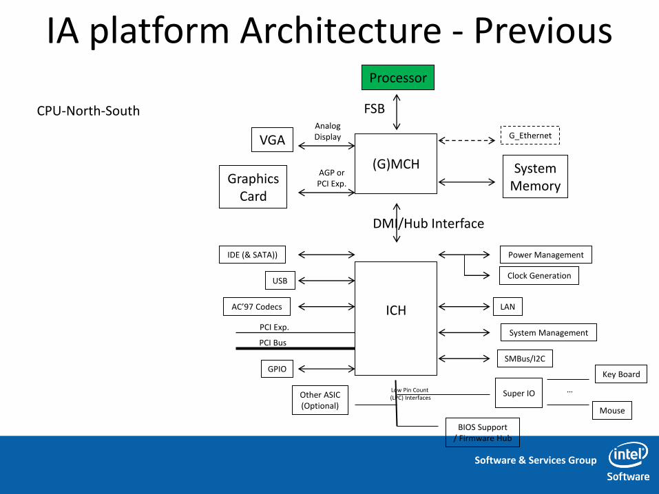
IA platform Architecture - Previous
CPU-North-South
Processor
FSB Analog Display VGA
AGP or PCI Exp. Graphics
Card
System Memory
(G)MCH
ICH
DMI/Hub Interface
IDE (& SATA))
USB
GPIO
Power Management
Clock Generation
LAN
System Management
SMBus/I2C
Other ASIC (Optional)
Super IO
BIOS Support / Firmware Hub
Low Pin Count (LPC) Interfaces
Key Board
Mouse
…
PCI Bus
G_Ethernet
PCI Exp.
AC’97 Codecs

Software & Services Group
IA platform Architecture - CedarTrail
CPU-PCH

Software & Services Group
IA platform Architecture - Medfield SOC

Software & Services Group
IA platform Architecture - Summary
SOC is coming

Software & Services Group
IA power management

Software & Services Group
Translating Technology Leadership into New Compelling Product Roadmaps

Software & Services Group
Transforming the PC - Lower Power Designs
Software & Services Group
Software & Services Group
Software & Services Group

Software & Services Group

Software & Services Group

Software & Services Group
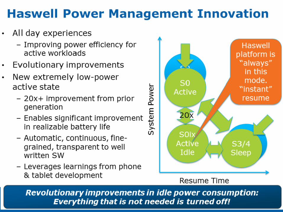
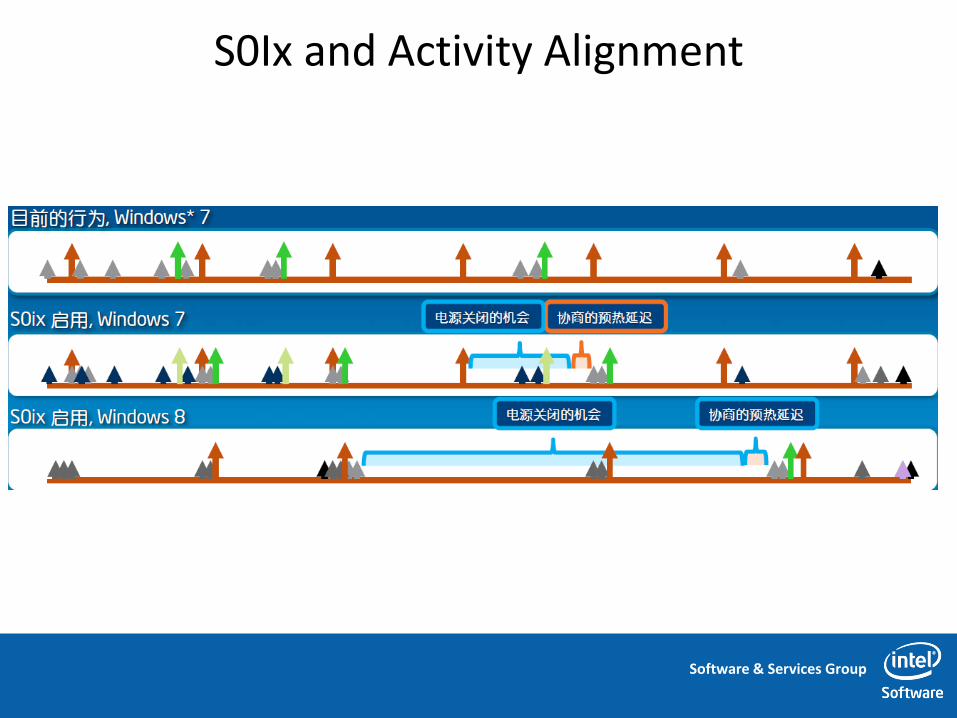
Improving Idle Efficiency
Software & Services Group
S0Ix and Activity Alignment

Software & Services Group
ACPI & CPU C/P states

Software & Services Group
ACPI Structure
Software & Services Group
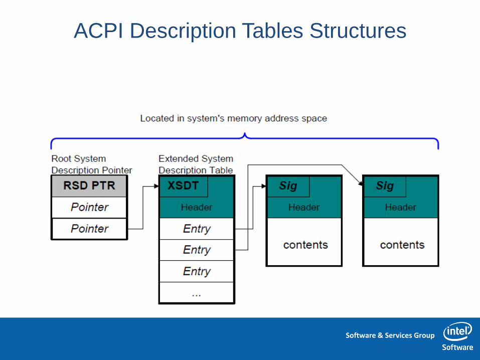
ACPI Description Tables Structures

Software & Services Group
ACPI Description Tables Structures

Software & Services Group
ACPI Global System Power States
Software & Services Group
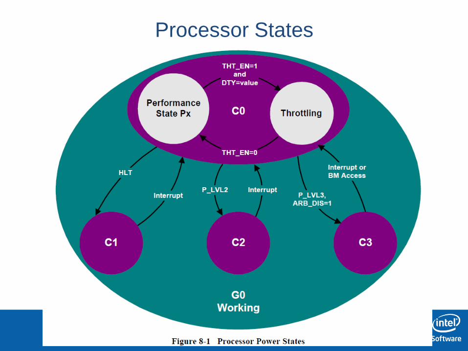
Processor States
Software & Services Group
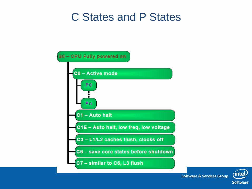
C States and P States

Software & Services Group
C States
• Processor Power consumption and thermal
management states
• Reduces power consumption by stopping the
processor
– Code only executes in the C0 state
• OS idle handlers maintain the C State policy
and perform C State transitions

Software & Services Group
C States – Contd.
• C0 (Full On) – Active Working State
– Can throttle the CPU to reduce CPU power consumption
• C1 (Auto-Halt) – Entered via STI-HLT instruction sequence
– no hardware support is needed from the chipset
– has no software-visible effects – maintain the context of the system caches
• C2 (Stop Grant) – a low-power state optimized around multiprocessor and
bus master systems
– has no software-visible effects
– has lower power and higher exit latency than the C1
– CPU keeping its caches coherent

Software & Services Group
C States
• C4 (Deeper Sleep) (Stop-Clock with lower CPU voltage)
– shuts down its PLL and cannot handle snoop requests – Deep Sleep plus reduction in core voltage
– continue to handle traffic to memory so long as this traffic does not
require a snoop
• C6 (Deep Power Down Technology)
– flush its cache and save its core context to a dedicated on-die SRAM – core processor’s voltage can be completely shut off.

Software & Services Group
C States
30

Software & Services Group
P States
• Multiple frequency and voltage points for optimal performance and power efficiency – eliminating the need for any coordination during the
frequency/voltage transition.
• Offers differing levels of operational efficiency while still in C0 – Core frequency and core voltage are changed in unison – An incremental shift in voltage is required to increase frequency for
any given processor • ƒ ~ V, P ƒ * V2 P ~ V3
• Leakage power ~ V2
– Thus, reducing performance by 20% can reduce power by ~50%

Software & Services Group
ACPI & CPU C/P states Lab
一.实验目的
– Know the ACPI, CPU C and P states concepts
– Know the how to test and control the C and P states
二.实验器材
– Atom Lab platform
– WinXP
三.实验预习要求
– Review the ACPI spec 4.0 chapter 8
四.实验内容
– Use tools to see the C states
– Use tools and test case to see P states different performance

Software & Services Group
IA IO Programming methodology Review
• IA device programming methodology is stable ,
despite of the platform Architecture change
“…each new kernel release sees about 70,000 new lines of ARM code, whereas there's roughly 5,000 lines of new x86 code added”

Software & Services Group
Intel IO Architecture • Different device types:
– OS virtual device
• Not real hardware
– ACPI device
• real hardware,
• not connected through PCI
bus
– PCI connected Device
• real hardware
• connected through PCI bus
• PCI/PCIE programming
interface device or leverage
PCI/PCIE programming to
control itself

Software & Services Group
• Our Target devices:
• PCI connected Device
– Standard and usually
cross platform
– Device has
hierarchical
connection
relationship
IA IO Architecture
Software & Services Group
Programming methodology
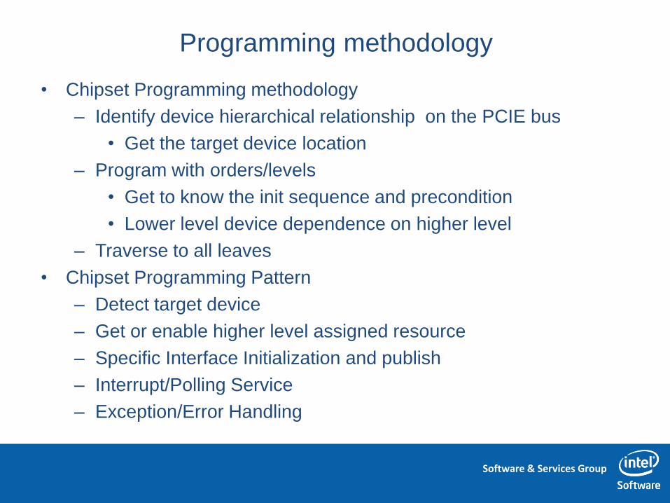
• Chipset Programming methodology
– Identify device hierarchical relationship on the PCIE bus
• Get the target device location
– Program with orders/levels
• Get to know the init sequence and precondition
• Lower level device dependence on higher level
– Traverse to all leaves
• Chipset Programming Pattern
– Detect target device
– Get or enable higher level assigned resource
– Specific Interface Initialization and publish
– Interrupt/Polling Service
– Exception/Error Handling

Software & Services Group
Case Study
• How could I enable my USB2.0 Flash disk?
• How could I enable the serial COM/UART port?

Software & Services Group
• Check the hierarchical
location for below devices:
– How could I enable my
USB2.0 Flash disk?
– How could I enable the serial
COM/UART port?
Case Study

Software & Services Group
Programming methodology – Question’s answer
• Enable the devices layer by layer:
EHCI
Super I/O
OHCI
PCI Bus
LPC
Usb Mouse
Usb Flash Disk
Layer1 : Init PCI Bus
Layer2: Init PCI/PCIE host device
Layer3: Init specific child device
COM

Software & Services Group
• Layer1: Init PCI Bus – Bios role
• Layer2: Init PCI/PCIE host device - Bios and OS
role
• Layer3: Init specific child device - Bios and OS
role
Case Study

Software & Services Group
Layer1: Init PCI Bus – What need to do
• Init or Enumerate PCI Bus:
1.Search all PCI device.
2.Assign PCI unique address (Bus number, for
plug in device under bridge)
3.Assign device required system resource
PCI Bus
Step1: Init PCI Bus
PciRootBridge

Software & Services Group
Layer1: Init PCI Bus – How to do it in Bios
• Go through whole PCI bus twice:
• First time: Detect the bridge, to assign the Bus number.
• - ensure the PCI configuration transaction can go through
related device.
• - Deep first, recursively
• Second time: Detect system resource and assign the device
system resource.
• - Bios Pci Bus driver will calculate whole required system
resource firstly, then assign them to different PCI devices.
• - Bios Pci Bus also report whole required system resource to
OS through ACPI table.
•

Software & Services Group
Layer1: Init PCI Bus – How to do it in Bios
• After Layer1 PciBus init, all PCI device is
enumerated and found out
– but we don’t know what specific PCI device they are.
PciIO
PciIO
ICH8 PCI Bus
PciIO
PciRootBridge
Layer1 : Init PCI Bus

Software & Services Group
Layer2: Init Host controller
• Which device is EHCI host controller?
• Which device is LPC host controller?
PciIO
PciIO
ICH8 PCI Bus
PciIO
PciRootBridge
Layer1 : Init PCI Bus
Software & Services Group
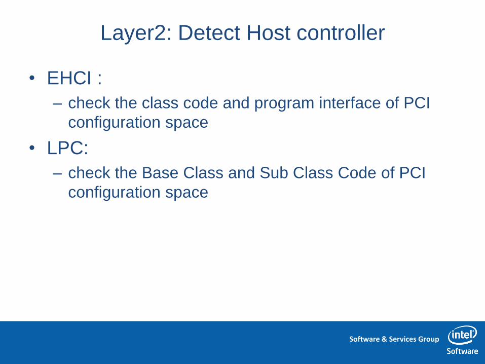
Layer2: Detect Host controller
• EHCI :
– check the class code and program interface of PCI
configuration space
• LPC:
– check the Base Class and Sub Class Code of PCI
configuration space
Software & Services Group
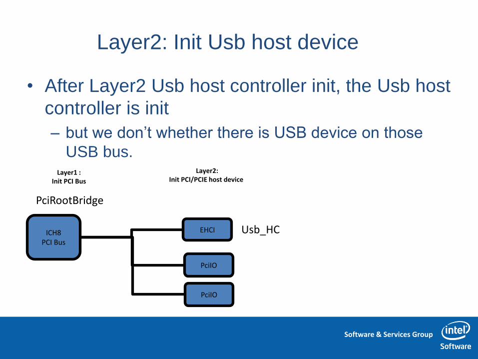
Layer2: Init Usb host device
• After Layer2 Usb host controller init, the Usb host
controller is init
– but we don’t whether there is USB device on those
USB bus.
EHCI ICH8 PCI Bus
PciIO
PciIO
Layer2: Init PCI/PCIE host device
PciRootBridge
Usb_HC
Layer1 : Init PCI Bus

Software & Services Group
Layer2: Init USB Bus
• After Layer2 USB bus init, all USB device is
enumerated and found out
– but we don’t know what specific Usb device they are.
EHCI ICH8 PCI Bus
PciIO
PciIO
UsbIO
Layer1 : Init PCI Bus
Layer2: Init PCI/PCIE host device
PciRootBridge Usb_HC
Usb_HC
Software & Services Group
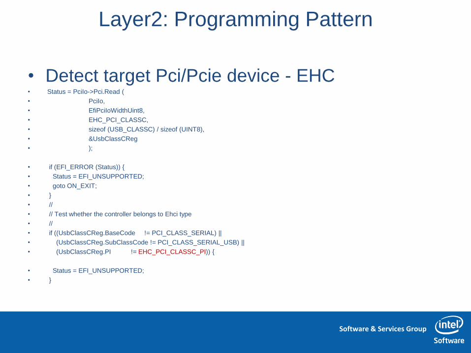
Layer2: Programming Pattern
• Detect target Pci/Pcie device - EHC • Status = PciIo->Pci.Read (
• PciIo,
• EfiPciIoWidthUint8,
• EHC_PCI_CLASSC,
• sizeof (USB_CLASSC) / sizeof (UINT8),
• &UsbClassCReg
• );
• if (EFI_ERROR (Status)) {
• Status = EFI_UNSUPPORTED;
• goto ON_EXIT;
• }
• //
• // Test whether the controller belongs to Ehci type
• //
• if ((UsbClassCReg.BaseCode != PCI_CLASS_SERIAL) ||
• (UsbClassCReg.SubClassCode != PCI_CLASS_SERIAL_USB) ||
• (UsbClassCReg.PI != EHC_PCI_CLASSC_PI)) {
• Status = EFI_UNSUPPORTED;
• }
Software & Services Group
Layer2: Programming Pattern
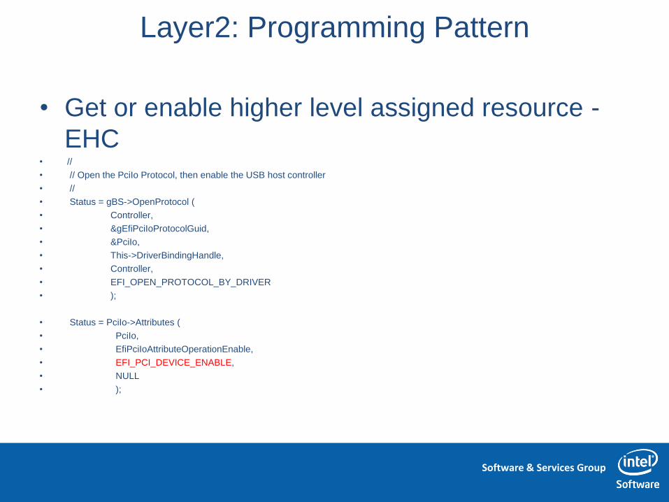
• Get or enable higher level assigned resource -
EHC • //
• // Open the PciIo Protocol, then enable the USB host controller
• //
• Status = gBS->OpenProtocol (
• Controller,
• &gEfiPciIoProtocolGuid,
• &PciIo,
• This->DriverBindingHandle,
• Controller,
• EFI_OPEN_PROTOCOL_BY_DRIVER
• );
• Status = PciIo->Attributes (
• PciIo,
• EfiPciIoAttributeOperationEnable,
• EFI_PCI_DEVICE_ENABLE,
• NULL
• );

Software & Services Group
Layer2: Programming Pattern
• Specific Interface Initialization and publish - EHC • //
• // Create then install USB2_HC_PROTOCOL
• //
• Ehc = EhcCreateUsb2Hc (PciIo);
• Status = gBS->InstallProtocolInterface (
• &Controller,
• &gEfiUsb2HcProtocolGuid,
• EFI_NATIVE_INTERFACE,
• &Ehc->Usb2Hc
• );
Software & Services Group
Layer2: Programming Pattern
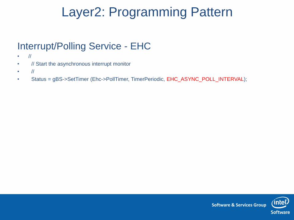
Interrupt/Polling Service - EHC • //
• // Start the asynchronous interrupt monitor
• //
• Status = gBS->SetTimer (Ehc->PollTimer, TimerPeriodic, EHC_ASYNC_POLL_INTERVAL);

Software & Services Group
Layer2: Programming Pattern
Exception/Error Handling -
EHC • if (EFI_ERROR (Status)) {
• return EFI_DEVICE_ERROR;
• }
• if (Ehc == NULL) {
• EHC_ERROR (("EhcDriverBindingStart: failed to create
USB2_HC\n"));
• Status = EFI_OUT_OF_RESOURCES;
• goto CLOSE_PCIIO;
• }
• if (EFI_ERROR (Status)) {
• EHC_ERROR (("EhcDriverBindingStart: failed to start async
interrupt monitor\n"));
•
• EhcHaltHC (Ehc, EHC_GENERIC_TIMEOUT);
• goto UNINSTALL_USBHC;
• }
UNINSTALL_USBHC:
gBS->UninstallProtocolInterface (
Controller,
&gEfiUsb2HcProtocolGuid,
&Ehc->Usb2Hc
);
FREE_POOL:
EhcFreeSched (Ehc);
gBS->CloseEvent (Ehc->PollTimer);
gBS->FreePool (Ehc);
CLOSE_PCIIO:
gBS->CloseProtocol (
Controller,
&gEfiPciIoProtocolGuid,
This->DriverBindingHandle,
Controller
);
return Status;

Software & Services Group
Layer3: Init specific child device
• Which USB device is Usb Flash disk?
• Where is COM/UART port and how to access it?
EHCI
OHCI
ICH8 PCI Bus
PCIIO
UsbIO
UsbIO
Layer1 : Init PCI Bus
Layer2: Init PCI/PCIE host device
PciRootBridge Usb_HC
Usb_HC

Software & Services Group
Layer3: USB device drivers
Usb Bus driver
Host controller driver
Usb Device driver
EHCI
PCI Bus
OHCI

Software & Services Group
Layer3: Programming Pattern
Detect target device – Usb Flash Disk • //
• // Get the interface to check the USB class and find a transport
• // protocol handler.
• //
• Status = UsbIo->UsbGetInterfaceDescriptor (UsbIo, &Interface);
• if (EFI_ERROR (Status)) {
• goto ON_EXIT;
• }
• Status = EFI_UNSUPPORTED;
• if (Interface.InterfaceClass != USB_MASS_STORE_CLASS) {
• goto ON_EXIT;
• }

Software & Services Group
Layer3: Programming Pattern
Get higher level assigned resource – Usb Flash Disk • Status = gBS->OpenProtocol (
• Controller,
• &gEfiUsbIoProtocolGuid,
• &UsbIo,
• This->DriverBindingHandle,
• Controller,
• EFI_OPEN_PROTOCOL_BY_DRIVER
• );
•
• Status = UsbIo->UsbGetInterfaceDescriptor (UsbIo, &Interface);
• if (EFI_ERROR (Status)) {
• DEBUG ((mUsbMscError, "UsbMassInitTransport: UsbIo->UsbGetInterfaceDescriptor (%r)\n", Status));
• goto ON_EXIT;
• }
Software & Services Group
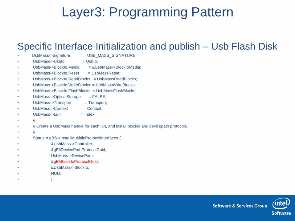
Layer3: Programming Pattern
Specific Interface Initialization and publish – Usb Flash Disk • UsbMass->Signature = USB_MASS_SIGNATURE;
• UsbMass->UsbIo = UsbIo;
• UsbMass->BlockIo.Media = &UsbMass->BlockIoMedia;
• UsbMass->BlockIo.Reset = UsbMassReset;
• UsbMass->BlockIo.ReadBlocks = UsbMassReadBlocks;
• UsbMass->BlockIo.WriteBlocks = UsbMassWriteBlocks;
• UsbMass->BlockIo.FlushBlocks = UsbMassFlushBlocks;
• UsbMass->OpticalStorage = FALSE;
• UsbMass->Transport = Transport;
• UsbMass->Context = Context;
• UsbMass->Lun = Index;
• //
• // Create a UsbMass handle for each lun, and install blockio and devicepath protocols.
• //
• Status = gBS->InstallMultipleProtocolInterfaces (
• &UsbMass->Controller,
• &gEfiDevicePathProtocolGuid,
• UsbMass->DevicePath,
• &gEfiBlockIoProtocolGuid,
• &UsbMass->BlockIo,
• NULL
• );
Software & Services Group
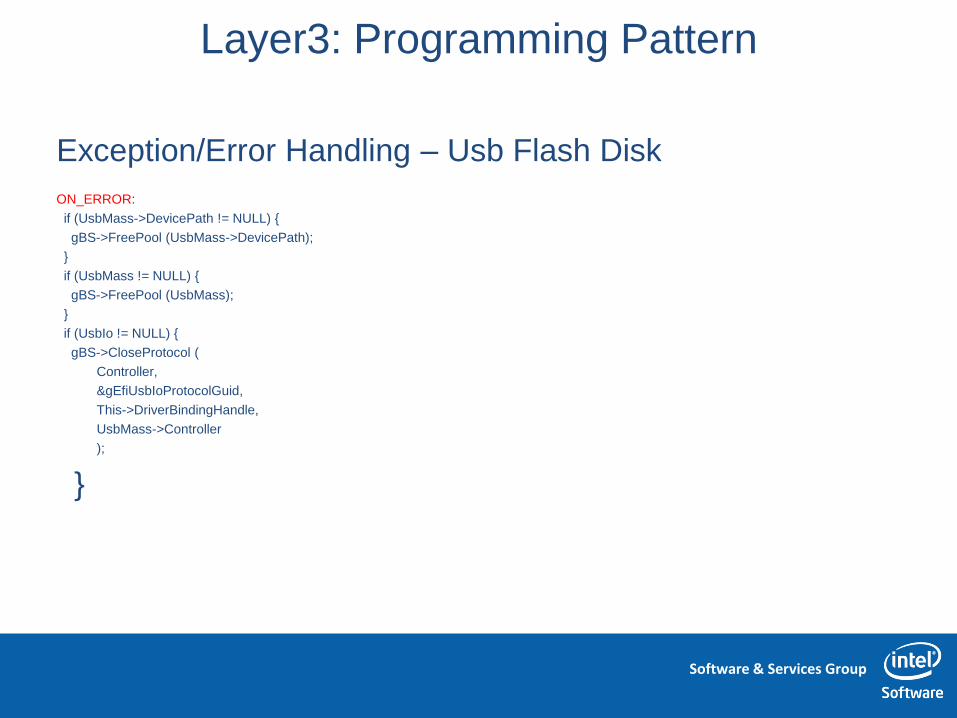
Layer3: Programming Pattern
Exception/Error Handling – Usb Flash Disk
ON_ERROR:
if (UsbMass->DevicePath != NULL) {
gBS->FreePool (UsbMass->DevicePath);
}
if (UsbMass != NULL) {
gBS->FreePool (UsbMass);
}
if (UsbIo != NULL) {
gBS->CloseProtocol (
Controller,
&gEfiUsbIoProtocolGuid,
This->DriverBindingHandle,
UsbMass->Controller
);
}

Software & Services Group
Layer2: Init LPC/SuperIO
•

Software & Services Group
Layer2: Init Host controller
• Which device is LPC host controller?
PciIO
PciIO
ICH8 PCI Bus
PciIO
PciRootBridge
Layer1 : Init PCI Bus

Software & Services Group
Layer2: LPC/SuperIO - W83627DHG-P
• Step 1: Enumerate PCI bus
to get the LPC bridge PCI
device
• Step 2: Enables decoding
on the LPC for the super
I/O (skipped in SCH,
always enabled by HW)
• Step 3: Configure the
SuperIo internal
component according to
platform policy
• Step 4: Now, we can use
the UART through IO
0x03F8-0x03FF register
block
Software & Services Group
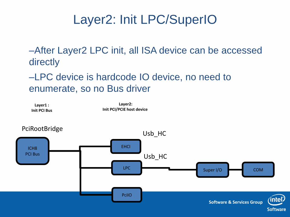
Layer2: Init LPC/SuperIO
–After Layer2 LPC init, all ISA device can be accessed
directly
–LPC device is hardcode IO device, no need to
enumerate, so no Bus driver
EHCI ICH8 PCI Bus
LPC
Layer1 : Init PCI Bus
Layer2: Init PCI/PCIE host device
PciRootBridge Usb_HC
Usb_HC
PciIO
Super I/O COM

Software & Services Group
Layer2: Programming Pattern
• Detect target Pci/Pcie device - LPC • //
• // Check whether the Pci device is the wanted LPC controller
• //
• Status = PciIo->Pci.Read (
• PciIo,
• EfiPciIoWidthUint32,
• 0,
• sizeof (Pci) / sizeof (UINT32),
• &Pci
• );
• if (!EFI_ERROR (Status)) {
• //
• // See if this is a standard PCI to ISA Bridge from the Base Code
• // and Class Code
• //
• if (Pci.Hdr.ClassCode[2] == PCI_CLASS_BRIDGE) { //Sub Class Code
• if (Pci.Hdr.ClassCode[1] == PCI_CLASS_ISA) { //Base Class Code
• Found = TRUE;
• break;
• }
• }
• }

Software & Services Group
Programming methodology
• Chipset Programming methodology
– Identify device hierarchical relationship on the PCIE bus
• Get the target device location
– Program with orders/levels
• Get to know the init sequence and precondition
• Lower level device dependence on higher level
– Traverse to all leaves
• Chipset Programming Pattern
– Detect target device
– Get or enable higher level assigned resource
– Specific Interface Initialization and publish
– Interrupt/Polling Service
– Exception/Error Handling

Software & Services Group
PCI/PCIE Device system resource Lab
一.实验目的
– Know the basic concepts of PCI/PCIE device
– Know PCI/PCIE device programming interface
– Know how to get assigned resource of PCIE device
二.实验器材
– Atom Lab platform
– Windows XP
三.实验预习要求
– Review the IA platform Programming methodology
四.实验内容
• Manually programming PCIE/PCI configuration space to get the
required system resource
• Manually read the PCIE/PCI configuration space to know the
assigned system resource

Software & Services Group
PCI/PCIE

Software & Services Group
PCI/PCIE Device Programming basic concept
PCI Express elements emulate PCI configuration environment
PCI-X Device
PCI-X Device
CPU
Host Bridge AGP GFX
PCI Bridge
PCI
PCI-X Bridge
PCI Bridge
PCI-X Bridge
PCI-X Device
PCI-X Device
Memory
PCI System
End point
Legacy End
point
Switch Switch
Switch
CPU
Root Complex PCI Express
GFX
PCI Bridge
PCI
Legacy End
point
End point
Memory
PCI Express System

Software & Services Group
PCI/PCIE “3D” Address Space
• A PCI target can implement up to three different types of
address space
– Configuration Space
• Stores basic information about the device
• Allows the central resource or O/S to program a device with optional setting
– I/O Space
• PCI device consumed system resource, permit device to map its internal
registers to those IO address.
• limited, used mainly with legacy peripherals, like Usb1.1 uhci, LPC/ ISA
– Memory Space
• PCI device consumed system resource, permit device to map its internal
registers to those volatile memory address.
• Used for just about everything else, modern PCI device, like Usb2.0 ehci
Software & Services Group
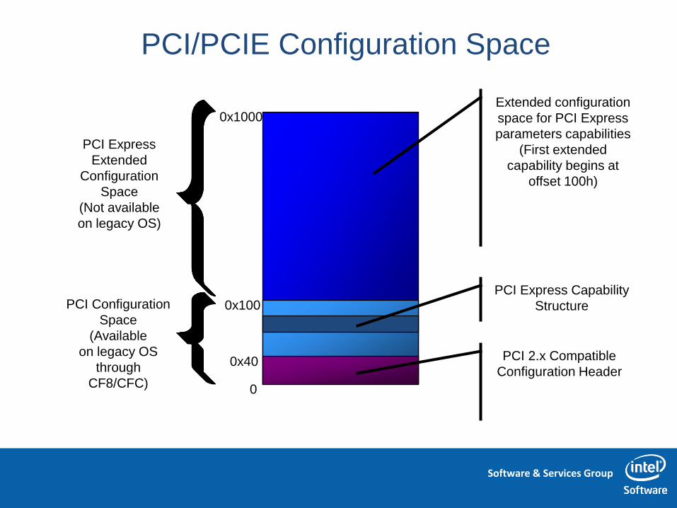
PCI/PCIE Configuration Space
PCI Express
Extended
Configuration
Space
(Not available
on legacy OS)
Extended configuration
space for PCI Express
parameters capabilities
(First extended
capability begins at
offset 100h)
0x1000
PCI Configuration
Space
(Available
on legacy OS
through
CF8/CFC)
PCI Express Capability
Structure
0
0x100
PCI 2.x Compatible
Configuration Header 0x40

Software & Services Group
PCI/PCIE Configuration Space
PCI Express
Extended
Configuration
Space
(Not available
on legacy OS)
0x1000
PCI Configuration
Space
(Available
on legacy OS
through
CF8/CFC) 0
0x100
0x40
Software & Services Group
PCI/PCIE IO Space
• This space is where legacy peripherals
(Keyboard, serial port, etc) are mapped.
• The PCI spec allows an agent to request 4 bytes
to 2GB of I/O space. But x86 processor only
supports an 64K I/O port.
• Modern PCI/PCIE device don’t prefer to
consume the IO space any longer.
Software & Services Group
PCI/PCIE Memory Space
• This space is used by most everything else – it’s
the general purpose address space
– The PCI spec recommends that a device use
memory space, even if it is a peripheral.
• An agent can request between 16 bytes and 2
GB of memory space
– The PCI Spec recommends that an agent use at least
4K of memory space, to reduce the width of the
agent’s address decoder.

Software & Services Group
System Resource Consumed
• Memory
• IO
• DMA (for legacy device only)
• IRQ

Software & Services Group
PCIE & Chipset Programming methodology
• Lab steps (实验步骤)
1. Find the target PCIE/PCI device through
DeviceID/VenderID
2. Stop the PCIE/PCI device
3. Preserve the original value
4. Write the Bars with allone
5. Read the Bars response values
6. Write back the original value

Software & Services Group
PCIE & Chipset Programming methodology
• Lab steps (实验步骤)
• 1. Find the target PCIE/PCI
device through
DeviceID/VenderID

Software & Services Group
PCIE & Chipset Programming methodology
• Lab steps (实验步骤)
• 2. Stop the PCIE/PCI device

Software & Services Group
PCIE & Chipset Programming methodology
• Lab steps (实验步骤)
• 4. Write the Bars with allone
• 5. Read the Bars response values

Software & Services Group
PCIE Programming methodology
Exercise and questions(实验习题与思考)
1. How a PCIE device expose its programming interface(PI)?
2. What’s the same and different between System Memory
Address, MMIO and IO?
3. Since the IO address is old, why we still maintain it?
4. How to know how many resource a PCIE device need through
its PI?
5. Please summary what type system resource the below
devices need? Ehci, SATA, SMBus
6. Please change the assigned resource to difference range in
BIOS or OS, and let it still work fine.

Software & Services Group
Usb3.0

Software & Services Group
Usb3.0 cable assembly

Software & Services Group
Usb3.0 cable assembly

Software & Services Group
Usb3.0 cable assembly
Software & Services Group
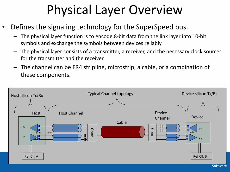
Physical Layer Overview • Defines the signaling technology for the SuperSpeed bus.
– The physical layer function is to encode 8-bit data from the link layer into 10-bit symbols and exchange the symbols between devices reliably.
– The physical layer consists of a transmitter, a receiver, and the necessary clock sources for the transmitter and the receiver.
– The channel can be FR4 stripline, microstrip, a cable, or a combination of these components.
Tx
Rx
Host Host Channel
Cable
Co
nn
Tx
Rx
Device Device Channel
Ref Clk A Ref Clk B
pins pads pads
Co
nn
Typical Channel topology Host silicon Tx/Rx Device silicon Tx/Rx

Software & Services Group
Differences From High-Speed
• High-Speed
– 480 MT/s
– No-SSC
– 2 wires for signaling
• Tx and Rx use same wire
• 1 bi-directional link
– DC coupled bus
– NRZ encoding
• SuperSpeed
– 5.0 GT/s
– SSC is required
– 4 wires for signaling
• 2 for Tx and 2 for Rx
• Each Uni-directional
– AC coupled bus
– 8b10b encoded
Device BHOST
+
-
+
-
+
-
+
-
Tx
Rx
Rx
Tx
Tx
Rx
+
-
+
-
+
-
+
- Tx

Software & Services Group
Usb3.0 Bus Architecture

Software & Services Group
Usb3.0 Packet Flow
Screen clipping taken: 2011/7/25, 10:10
Software & Services Group
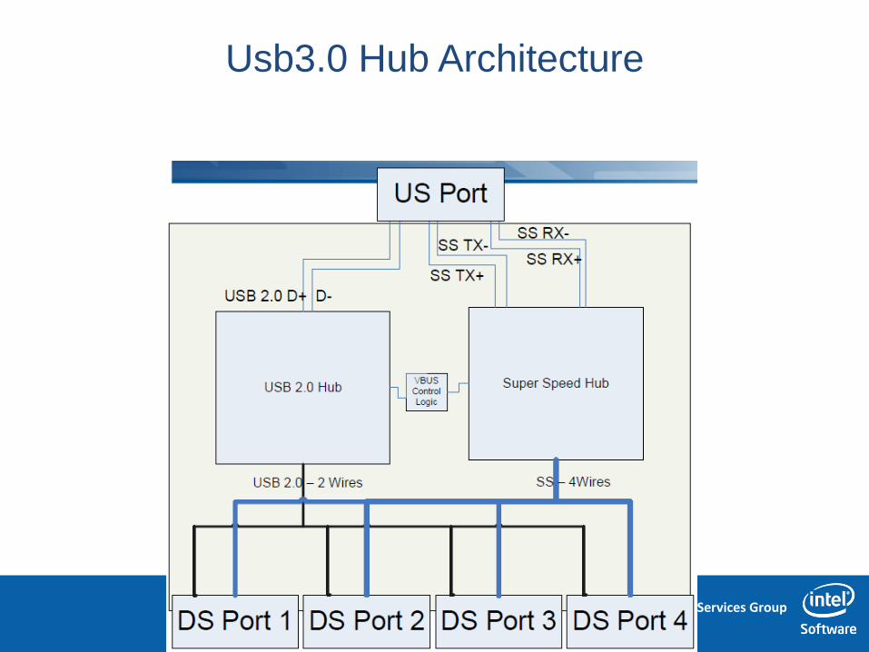
Usb3.0 Hub Architecture

Software & Services Group
USB overview
• Host, hub and device build up the topology map, one HC one
Bus
– UHC/OHC: Usb1.1
– EHC: Usb2.0
– XHC: Usb3.0
• 4 transfer speeds: low (1.1), full(1.1), high(2.0), super
high(3.0)
• 4 transfer types: control, bulk, interrupt, isochronous
• Plug and play
• Support power management
• USB 1.1&2.0 is a polled bus, it is the host to device or device
to host transfer mode, not the point to point mode (But
USB3.0 is PtP)

Software & Services Group
USB2.0 Basic programming concept
Usb Bus driver
Host controller driver
Usb Device driver
EHCI
PCI Bus
OHCI

Software & Services Group
USB Basic programming concept
Usb Bus driver
Host controller driver
Universal Serial Bus Specification 3.0 Universal Serial Bus Specification 2.0
eXtensible Host Controller Interface Enhanced Host Controller Interface Specification Universal Host Controller Interface (UHCI) Design Guide Open Host Controller Interface Specification
Device Class Definition for Human Interface Devices Mass Storage Class Bulk-Only Transport spec Usb Device driver

Software & Services Group
USB Basic programming concept
UsbMassStorage
Usb Bus driver
UsbKB
UsbIO
BLKIO TxtIn
EHC driver
UsbMouse
OHC driver
Pointer
UsbIO UsbIO
Usb2_HC Usb2_HC Layer2

Software & Services Group
USB Basic programming concept
92

Software & Services Group
USB Basic programming concept
• Device States:
– Attached
– Powered
– Default
– Address
– Configured
93

Software & Services Group
USB Basic programming concept

Software & Services Group
USB2.0 host controller drivers
Usb Bus driver
Host controller driver
Usb Device driver
EHCI
PCI Bus
OHCI

Software & Services Group
EHCI Programming interface
•

Software & Services Group
EHCI Programming interface
• Memory Space
FrameList
Periodic QH
Async QH
MM IO
B0:D29:F7
PCI Configuration Space
EHC MMIO Op regs block

Software & Services Group
Architecture of EHCI

Software & Services Group
EHCI Programming interface

Software & Services Group
EHCI Programming interface
•

Software & Services Group
EHCI Programming interface
• Memory Space
FrameList
Periodic QH
Async QH
MM IO
B0:D29:F7
PCI Configuration Space
EHC MMIO Op regs block
Control
Isochronous
Bulk
Interrupt
USB standard Transfer

Software & Services Group
USB Bus Enumeration
102
Usb Bus driver
Host controller driver
Usb Device driver
EHCI
ICH8 PCI Bus
UHCI
Software & Services Group
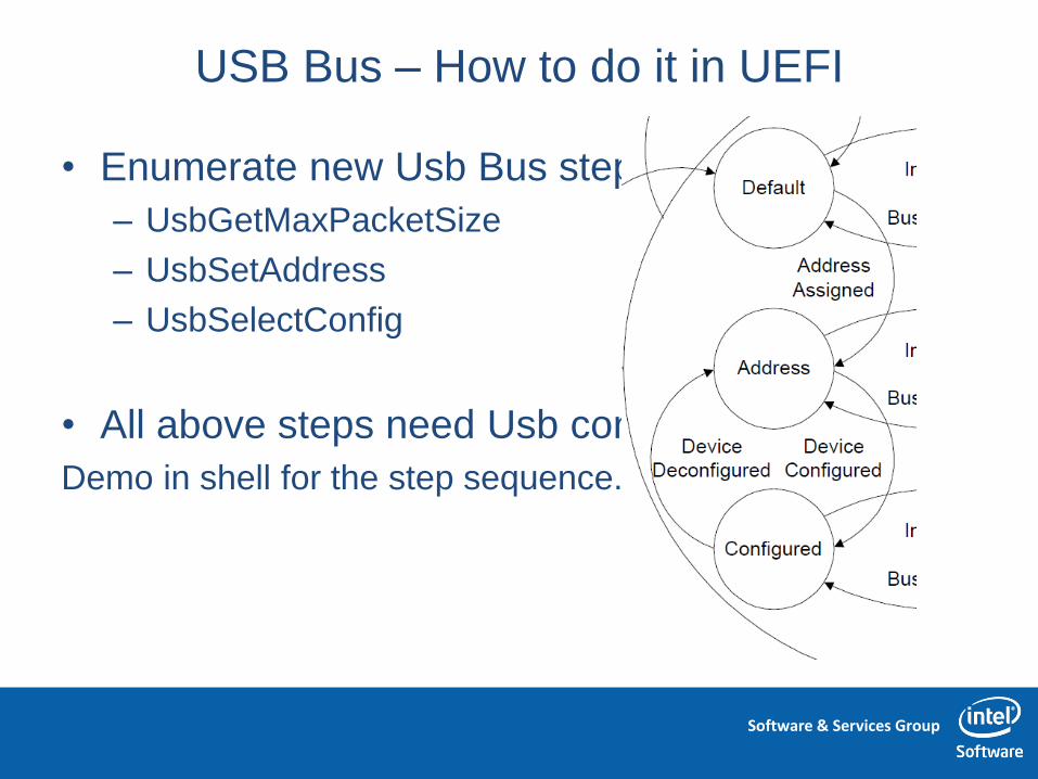
USB Bus – How to do it in UEFI
• Enumerate new Usb Bus steps:
– UsbGetMaxPacketSize
– UsbSetAddress
– UsbSelectConfig
• All above steps need Usb control transfer
Demo in shell for the step sequence.

Software & Services Group
eXtensible Host Controller Interface

Software & Services Group
eXtensible Host Controller Interface
Usb Bus driver
Host controller driver
Usb Device driver
XHCI
PPT PCI Bus
EHCI

Software & Services Group
Usb3.0 and Usb2.0 Driver relations
UsbMassStorage
Usb Bus driver
xHC driver
UsbKB
UsbIO
BLKIO TxtIn
EHC driver
UsbMouse
UHC driver OHC driver
Pointer
Usb2_HC
UsbIO UsbIO
Usb2_HC Usb2_HC Usb2_HC

Software & Services Group
General Architecture of XHCI

Software & Services Group
Xhci v.s. Ehci/Uhci for programming
• Ehci/Uhci
– Device states unrelated
– Hardware is simple
– Software own and track all
device info
– Software own the detail
transactions level schedule,
need create every transaction
for a transfer
• Xhci
– Device states unrelated
– Hardware is complex
– Hardware own and track
device info
– Software only own the transfer
level schedule, need not
create detail transaction for a
transfer
Device BHOST
+
-
+
-
+
-
+
-
Tx
Rx
Rx
Tx
Tx
Rx
+
-
+
-
+
-
+
- Tx
Software & Services Group
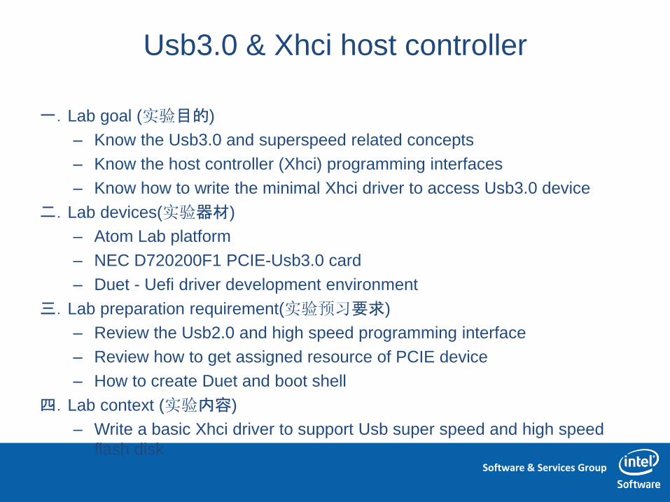
Usb3.0 & Xhci host controller
一.Lab goal (实验目的)
– Know the Usb3.0 and superspeed related concepts
– Know the host controller (Xhci) programming interfaces
– Know how to write the minimal Xhci driver to access Usb3.0 device
二.Lab devices(实验器材)
– Atom Lab platform
– NEC D720200F1 PCIE-Usb3.0 card
– Duet - Uefi driver development environment
三.Lab preparation requirement(实验预习要求)
– Review the Usb2.0 and high speed programming interface
– Review how to get assigned resource of PCIE device
– How to create Duet and boot shell
四.Lab context (实验内容)
– Write a basic Xhci driver to support Usb super speed and high speed
flash disk

Software & Services Group
Usb3.0 & Xhci host controller
Exercise and questions(实验习题与思考)
1. Does Usb3.0 equal SuperSpeed?
2. Does the Usb3.0 host controller support Usb2.0 high speed
device? How?
3. Is the Usb interrupt transfer a real interrupt way?
4. What transfer type a standard Usb flash disk need? What
about Usb Mouse and keyboard?
5. What’s the programming interface design differences among
the Uhci/Ohci, Ehci and Xhci? Why?
6. Please try to minimize and port the Uefi Xhci driver to
Meego/Vxworks/Linux to support a Usb KB or Usb Flash disk?
7. Please complete the Isochronous Transfer in UEFI
Software & Services Group
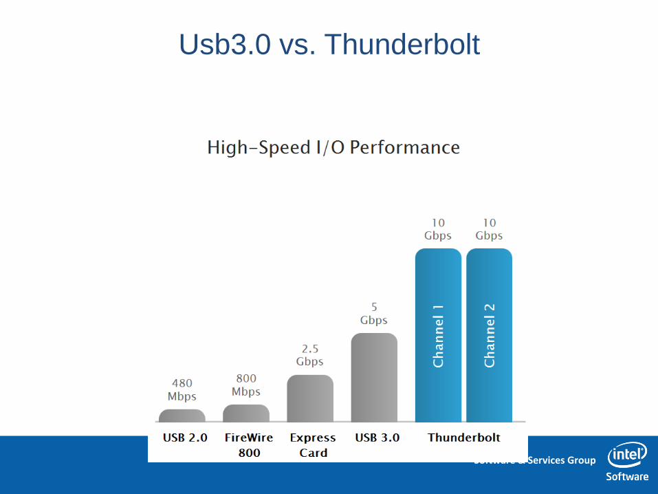
Usb3.0 vs. Thunderbolt

Software & Services Group
Thunderbolt Overview
Software & Services Group
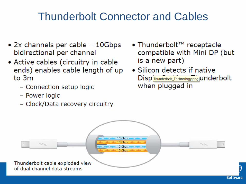
Thunderbolt Connector and Cables

Software & Services Group
Example Daisy Chain Configuration

Software & Services Group
Daisy Chain and Native Display

Software & Services Group
Example Thunderbolt Device

Software & Services Group
Quiz questions
(实验习题与思考)
1. How many major chip there will be in IA client system
(Embedded, Cellphone, Tablet, Netbook, Notebook,
Desktop)?
A. 1
B. 2
C. 3
• Answer is A
Software & Services Group
Quiz questions
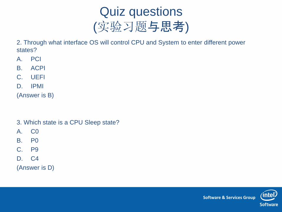
(实验习题与思考) 2. Through what interface OS will control CPU and System to enter different power
states?
A. PCI
B. ACPI
C. UEFI
D. IPMI
(Answer is B)
3. Which state is a CPU Sleep state?
A. C0
B. P0
C. P9
D. C4
(Answer is D)

Software & Services Group
Quiz questions
(实验习题与思考) 4. Which is the basic Bus to connect various IO devices in IA platform?
A. 1394
B. PCIE
C. USB3.0
D. Thunderbolt
(Answer is B)
5. Which IO Bus is not serial bus?
A. PCI
B. PCIE
C. USB3.0
D. Thunderbolt
(Answer is A)
Software & Services Group
120