power electronic grid simulator - national renewable ... · pdf file§jet engine §gas...
TRANSCRIPT

Power Electronic Grid SimulatorPlatform of drives and power qualityproducts for wind-turbine testing
Ester Guidi, Pieder Jörg, ABB Medium Voltage Drives, Switzerland
© ABBMonth DD, YYYY | Slide 1
Outline
§ Teststand applications for drives and power electronics
§ Modular drives and power-electronics platform ACS6000
§ Power electronic grid simulator based on platform
§ Design considerations following windturbine testingrequirements
© ABB GroupJune 11, 2013 | Slide 2

© ABB GroupJune 11, 2013 | Slide 3
Teststand applications for drives and power electronics
Test stand applications
single-drive multi-drive
Device under test
AC
DC
DC
AC
M
DC
AC
GARU
AC
DC
DC
AC
M
motoring OR generating motoring AND generating

© ABB GroupJune 11, 2013 | Slide 4
fixed installation
Teststand applications for drives and power electronics
Test stand applications
single-drive
motored device testing
AC
DC
DC
AC
M
AC
DC
DC
AC
M DUT
Device under test

© ABB GroupJune 11, 2013 | Slide 5
§ Gearbox§ Electrical generator§ Electrical motor§ Grid simulation§ Wind turbine§ …
ABB’s areas of activity
Test stand applications
Single drive Multi drive
Device testing§ Compressor & turbo charger§ Pump§ Balancing plant§ Jet engine§ Gas Turbines§ Motor Generator set, …
Fix installations§ Wind tunnel§ Human centrifuge (pilot training)§ Soft starters for high energy labs

Teststand applicationsTypical requirements towards electrics/automation
§ High dynamic electric motor control over wide speed range
§ capability to control induction and synchronous motors
§ base speed of electrical motor:1Hz .. 75Hz / few rpm .. 3600rpm
§ wide field-weakening range (… 1:5)
§ high torque over-loadability (… 275%)
§ air-gap-torque control bandwidth (… 400Hz)
§ flexible automation integration (PLC, FB, fast I/O …)
§ Versatile power electronic building blocks
§ load-cycling capable (reliability)
§ parallelable and multi-terminal capable (scalability)
© ABB GroupJune 11, 2013 | Slide 6

Outline
§ Teststand applications for drives and power electronics
§ Modular drives and power-electronics platform ACS6000
§ Power electronic grid simulator based on platform
§ Design considerations following windturbine testingrequirements
© ABB GroupJune 11, 2013 | Slide 7
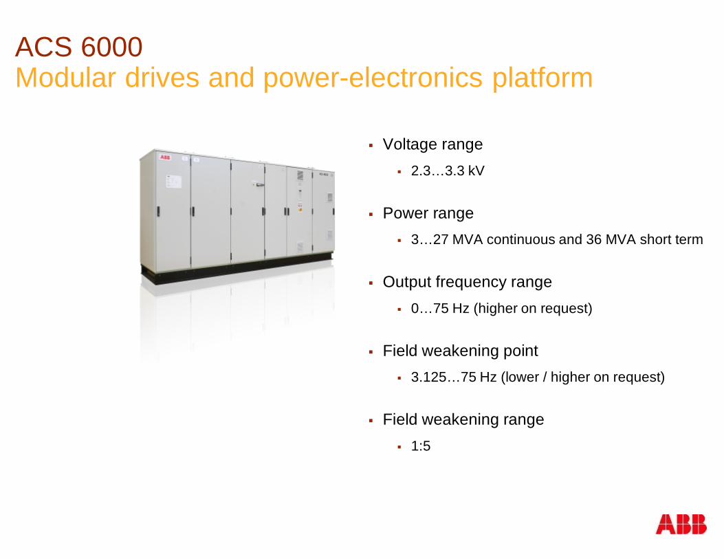
ACS 6000Modular drives and power-electronics platform
§ Voltage range§ 2.3…3.3 kV
§ Power range§ 3…27 MVA continuous and 36 MVA short term
§ Output frequency range§ 0…75 Hz (higher on request)
§ Field weakening point§ 3.125…75 Hz (lower / higher on request)
§ Field weakening range§ 1:5

ACS 6000 focus: Demanding applications
Chemical, Oil & Gas
Power Water
Marine
Pulp & Paper Special applications,e.g. wind tunnels
MetalsCement, Mining &Minerals

Inverter Unit
§ Power
§Stack(s)
Pre-defined
interfaces
for power,
cooling &
control
connections
ACS 6000: Some building blocksActive Rectifier
INU1 – 5MVA
Inverter Unit
Capacitor Bank
CBU LSU
Diode Rectifier Water Cooling
WCU
…INU5 – 9MVA
ARU5 – 9MVA
© ABB GroupJune 11, 2013 | Slide 113BHT490558R0001 Rev. A
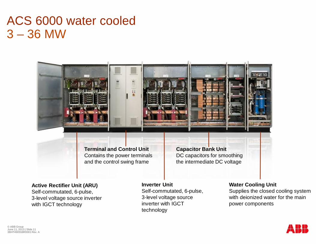
Terminal and Control UnitContains the power terminalsand the control swing frame
Inverter UnitSelf-commutated, 6-pulse,3-level voltage sourceinverter with IGCTtechnology
Capacitor Bank UnitDC capacitors for smoothingthe intermediate DC voltage
Water Cooling UnitSupplies the closed cooling systemwith deionized water for the mainpower components
ACS 6000 water cooled3 – 36 MW
Active Rectifier Unit (ARU)Self-commutated, 6-pulse,3-level voltage source inverterwith IGCT technology
© ABB GroupJune 11, 2013 | Slide 123BHT490558R0001 Rev. A
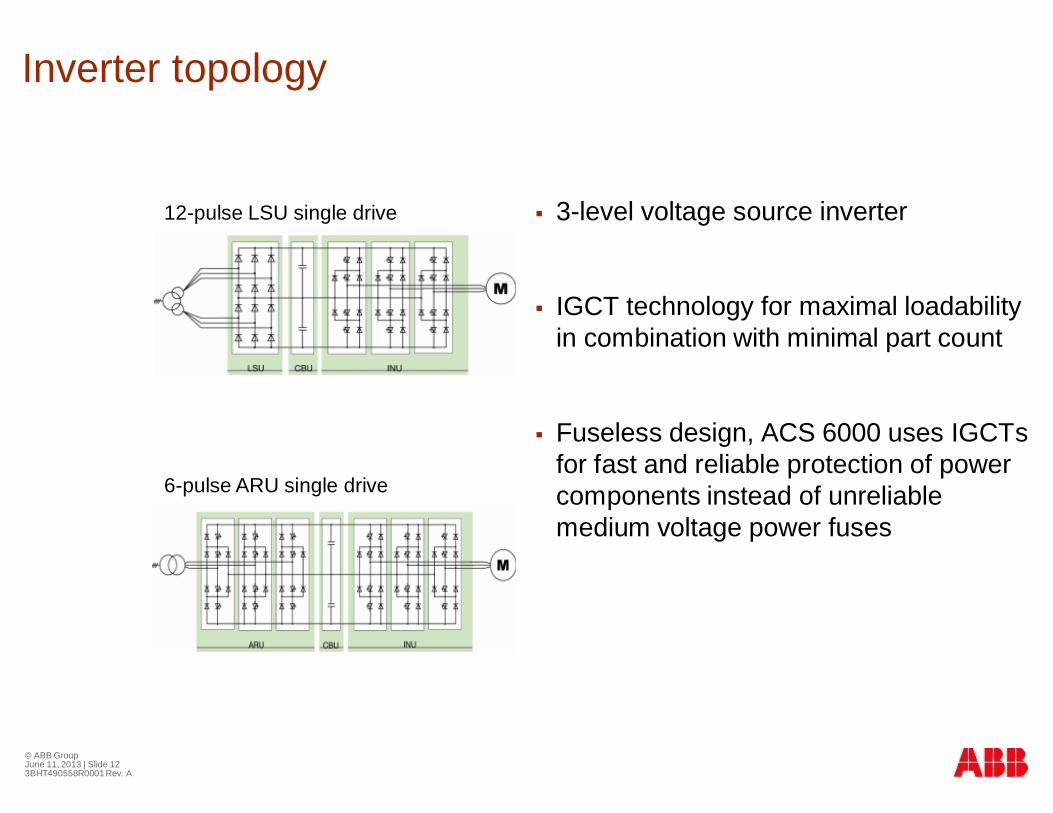
Inverter topology
§ 3-level voltage source inverter
§ IGCT technology for maximal loadabilityin combination with minimal part count
§ Fuseless design, ACS 6000 uses IGCTsfor fast and reliable protection of powercomponents instead of unreliablemedium voltage power fuses
12-pulse LSU single drive
6-pulse ARU single drive

© ABB GroupJune 11, 2013 | Slide 133BHT490558R0001 Rev. A
Common DC bus
§ Several motors (induction andsynchronous) can be connected to thesame DC busà optimized energy flow
§ Braking energy generated in onemotor can be transferred to otherinverters via common DC buswithout power consumption fromsupply network
§ Optimum configuration can bereached by combining different inverterand rectifier modules within one drive
Optimized energy flowwith common DC bus,e.g. cold reversingsteel mill

ACS 6000: INU configurations
e.g. 9MVA unit
=~~
=~~
=~~
=~~
=~~
Hard-parallel
Parallel… of two units … of three units
=~~
=~~
=~~
=~~
=~~
Parallel connection of inverter units:
9, 18, 27, 36MVA as standard
… of four units
=~~
=~~
=~~
…
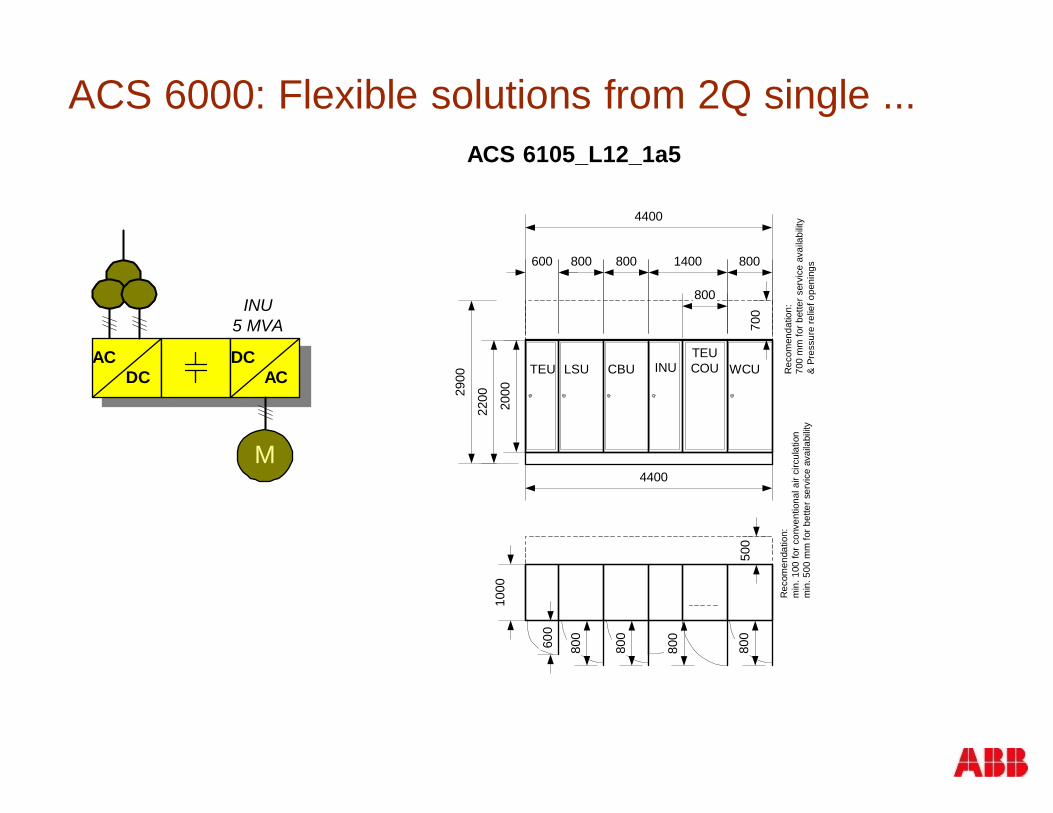
ACS 6000: Flexible solutions from 2Q single ...
4400
1000
220029
00
2000
4400
Rec
omen
datio
n:m
in.1
00fo
rcon
vent
iona
lair
circ
ulat
ion
min
.500
mm
forb
ette
rser
vice
avai
labi
lity
Rec
omen
datio
n:70
0m
mfo
rbet
ters
ervi
ceav
aila
bilit
y&
Pres
sure
relie
fope
ning
s
500
700
CBU
800
800
WCU
800
800
LSU
800
800
TEU
600
600
03.11.2002ACS 6107_L12_1a3_layout.vsd
1400
800
800
TEUCOUINU
AC DC
DC AC
M
INU5 MVA
ACS 6105_L12_1a5

ACS 6000: ... to 4Q multi drive
ACM 6209_A12_1s9_1s9_1s9
16900
1000
ARU
1500
750
ARU
1500
750
INU
2100
750
TEU
42004000
2200
2000
TEUCOU
1000
500
INU
2100
750
TEU
COU
INU
2100
750
TEU
COU
WCU
2000
1000
VLU
600
600
4300
EXU
800
800
EXU
800
800
4400
EXU
800
800
CBU
800
800
CBU
80080
0
AC DC
DC AC
M
AC DC
DC AC
M
DC AC
M
INU9 MVA
INU9MVA
INU9 MVA
ARU2x9 MVA

Outline
§ Teststand applications for drives and power electronics
§ Modular drives and power-electronics platform ACS6000
§ Power electronic grid simulator based on platform
§ Design considerations following windturbine testingrequirements
© ABB GroupJune 11, 2013 | Slide 17
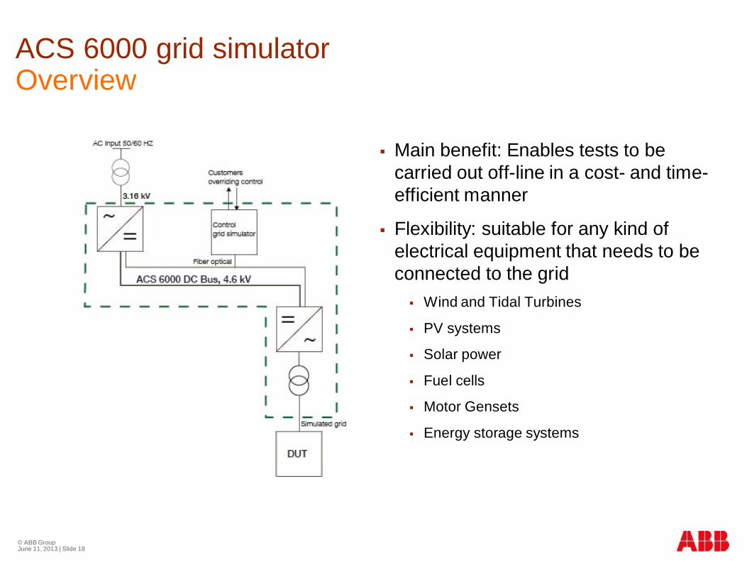
ACS 6000 grid simulatorOverview
© ABB GroupJune 11, 2013 | Slide 18
§ Main benefit: Enables tests to becarried out off-line in a cost- and time-efficient manner
§ Flexibility: suitable for any kind ofelectrical equipment that needs to beconnected to the grid§ Wind and Tidal Turbines
§ PV systems
§ Solar power
§ Fuel cells
§ Motor Gensets
§ Energy storage systems
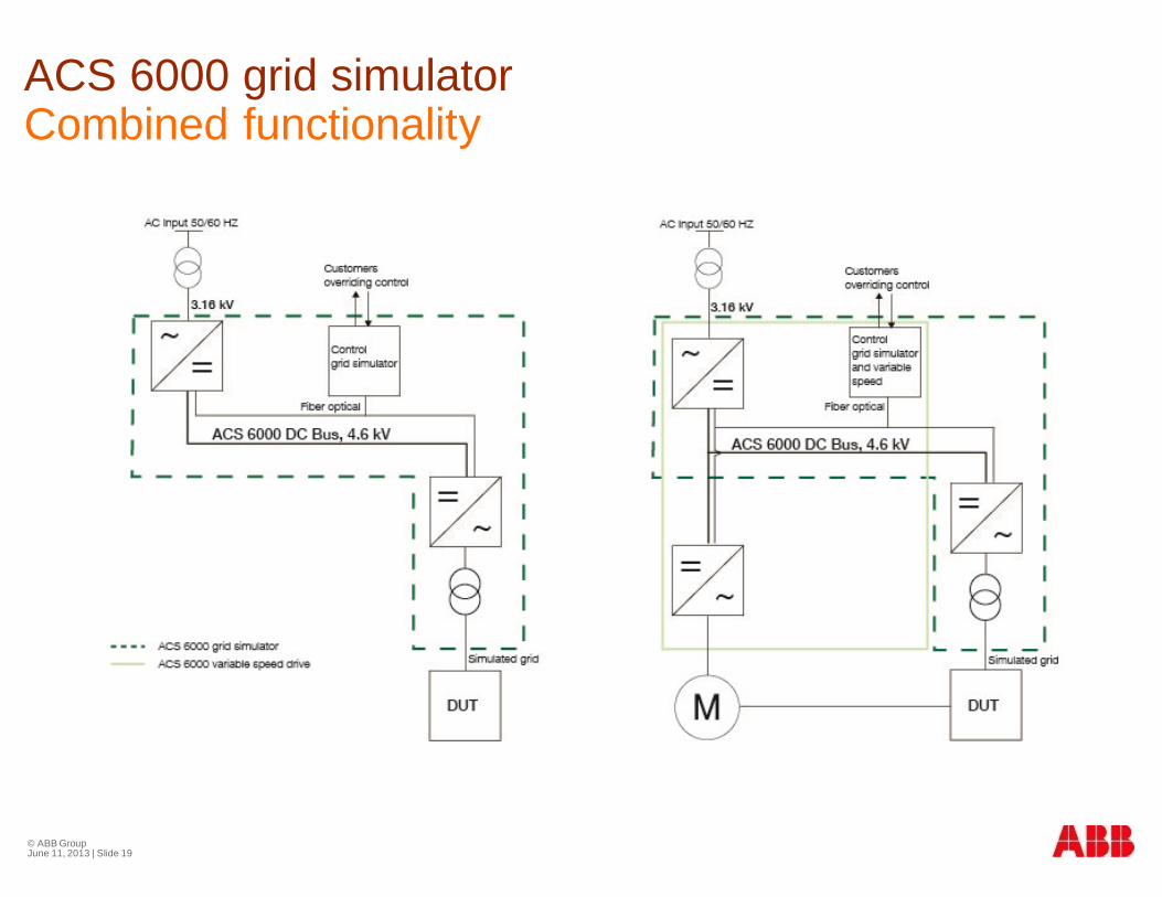
ACS 6000 grid simulatorCombined functionality
© ABB GroupJune 11, 2013 | Slide 19
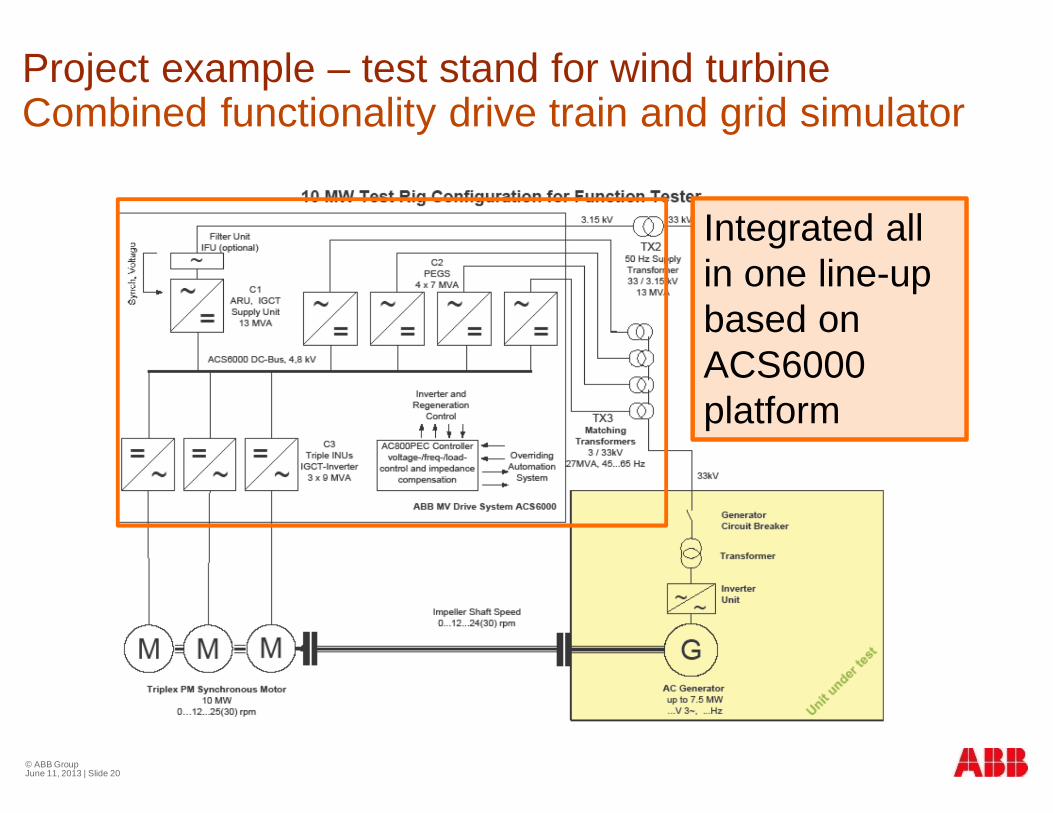
Project example – test stand for wind turbineCombined functionality drive train and grid simulator
© ABB GroupJune 11, 2013 | Slide 20
Integrated allin one line-upbased onACS6000platform

ACS 6000 grid simulatorExample of a layout and dimensions
© ABB GroupJune 11, 2013 | Slide 21

ACS 6000 grid simulatorLayout possibilies
§ U-shape, L-shape, …
© ABB GroupJune 11, 2013 | Slide 22

Outline
§ Teststand applications for drives and power electronics
§ Modular drives and power-electronics platform ACS6000
§ Power electronic grid simulator based on platform
§ Design considerations following windturbine testingrequirements
© ABB GroupJune 11, 2013 | Slide 23
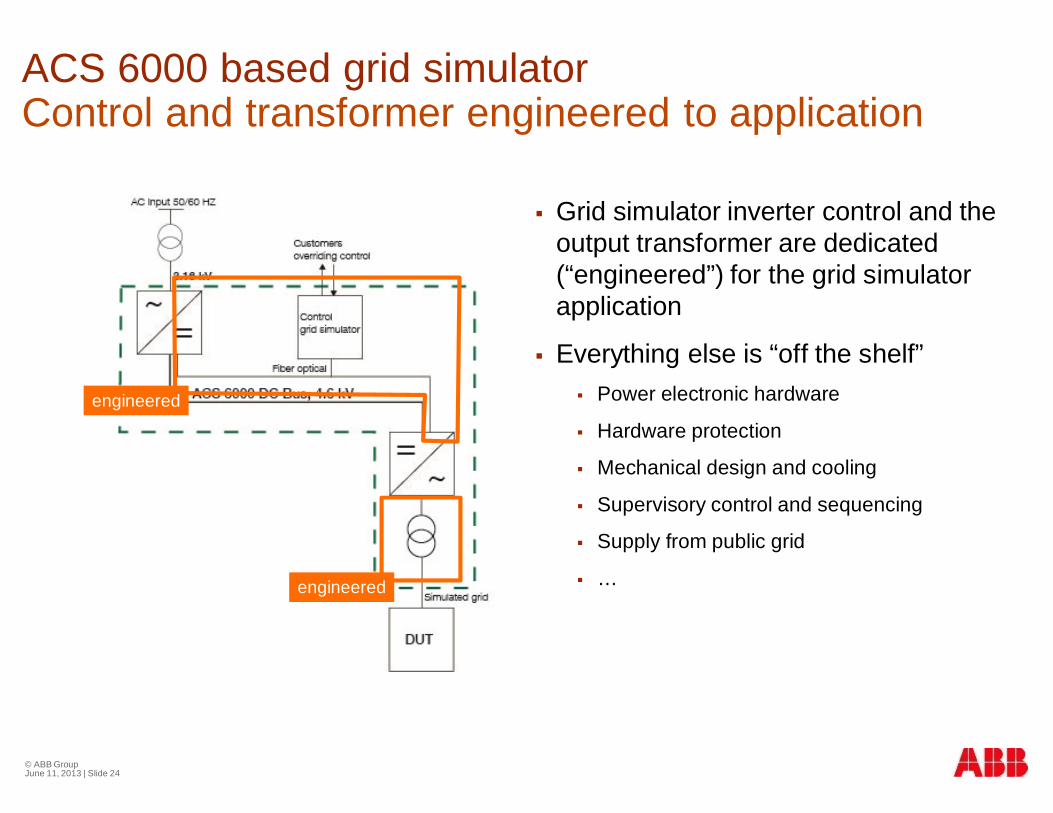
ACS 6000 based grid simulatorControl and transformer engineered to application
© ABB GroupJune 11, 2013 | Slide 24
§ Grid simulator inverter control and theoutput transformer are dedicated(“engineered”) for the grid simulatorapplication
§ Everything else is “off the shelf”§ Power electronic hardware
§ Hardware protection
§ Mechanical design and cooling
§ Supervisory control and sequencing
§ Supply from public grid
§ …
engineered
engineered

© ABB GroupJune 11, 2013 | Slide 25
ACS 6000 grid simulatorControl hardware overview
ACS6000
AC800 PEC
AMCAMC
PUBPUB
INT(INU1)
INT(INU2)
INT(INU3)
INT(INU4)
INT(ARU)
PFF
PECIO
Meas
PFF
Supervisior
Modbus
Modbus
Modbus
Vref
3
VPCC IPCC
33
RBU
Optical link pair Analogue Fieldbus
ProtectionIO
Digital engineered

© ABB GroupJune 11, 2013 | Slide 26
ACS 6000 grid simulatorControl hardware features
§ Main controller - PP D113§ 36 Optical fiber modules (25us)
§ DDCS (DriveBus Comm)
§ Communication to the upper control viaAnybus-Modules or CEX
§ Profibus-DPV1 Master
§ CANopen Slave
§ ControlNet Slave
§ DeviceNet Slave
§ Modbus-RTU S, -TCP S
§ Profibus-DP S, -DPV1 S, EtherCAT S
§ Profinet RTI - IO
§ Fast IO – UA D149§ PowerLink (native protocol – 25 us)
§ 32 DI (24V)
§ 16 DO (24V)
§ 12 AI (±10V, ±20mA)
§ Isolated in groups of 3
§ 4 isolated AO (±10V, ±20mA)
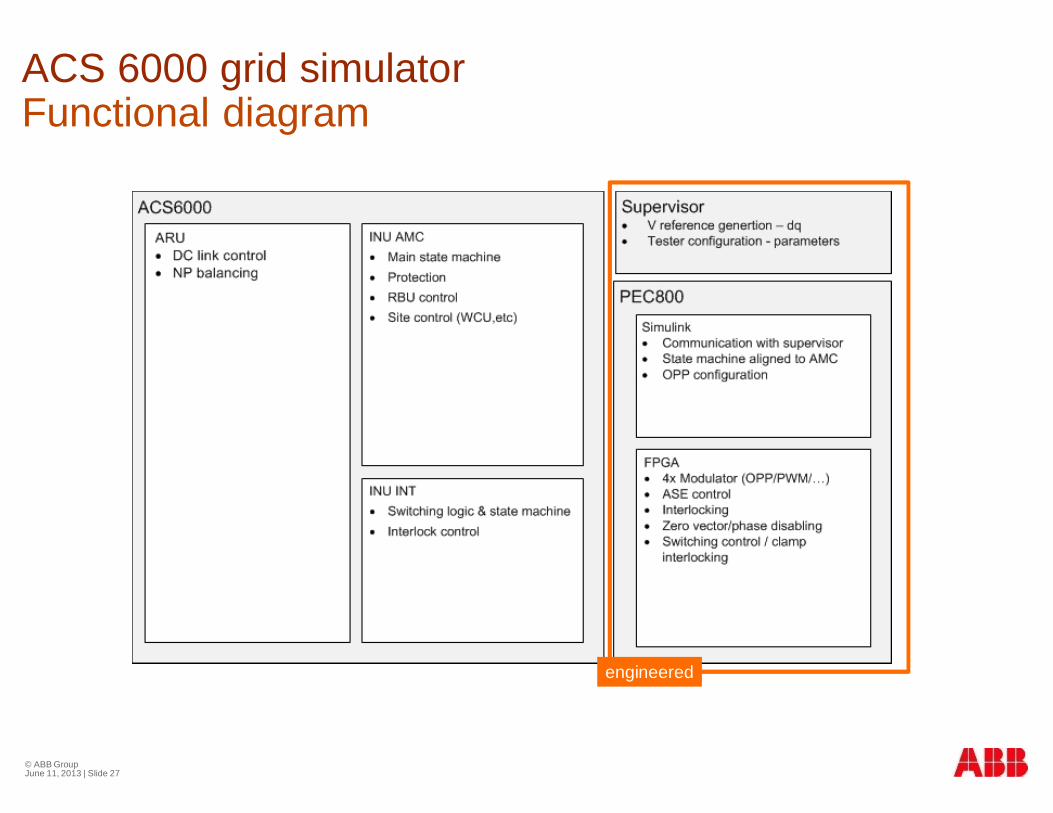
ACS 6000 grid simulatorFunctional diagram
© ABB GroupJune 11, 2013 | Slide 27
engineered

Overview: Configurations of matching transformer
§ Match the converter voltage to the desired testbus-voltage
§ Sum-up the power (resp. currents) of the different inverters,e.g. of 4 inverters
§ Cancel inverter harmonics to improve THDv
§ Provide galvanic insulation between DUT and simulator forsimpler test-design and protection
What is the function of the transformer
© ABB Group

Overview: Configurations of matching transformer
§ What doesn‘t work
§ 3 winding transformer („12-pulse“)à circulating currents
§ Parallel transformersà circulating currents
§ What basically works
§ Series connection of HV winding for summing up
§ Y configuration of LV winding with starpoint to NP
§ Delta configuration of LV winding
§ 3 single phase trafos with H-bridge driven LV winding
What works and what not
© ABB Group

Overview: Configurations of matching transformer
§ Series connection allows summation of voltages withcancellation of harmonic voltages
§ This turns the separate inverter units into a multi-level/multi-cell converter
§ Tapings are relatively easy to implement
§ The star-point is accessible and can be freely treated (hardgrounded, soft-grounded)
HV side configuration: Series connection
© ABB Group
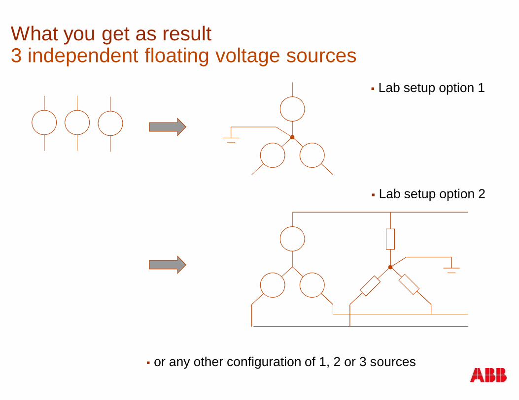
What you get as result3 independent floating voltage sources
§ Lab setup option 1
§ Lab setup option 2
§ or any other configuration of 1, 2 or 3 sources

How does the voltage source look likePotential and achievable short-circuit power
≈
inverter is idealvoltage source withno internalimpedance
it can run up to amaximum current
transformer leakageinductance is visiblegrid impedance duringnormal operation
minimum is ~5% ofrated transformer power
transformer thermalrating defines the short-circuit currents, that thegrid simulator can reallysink or source
maximum is installedpower electronic power
e.g.3.15kVAC_LL / 2000A11MVA per unit44MVA for 4 units
e.g.16MW cont. rating5%à 320MVAshort-circuit power
e.g.converter will limitshort-circuit at44MVA
Conclusion
§ ABB builds the grid simulators on a platform, which iswidely used in demanding industrial applications
§ The grid simulator is enabled by an application specificcontrol hardware and software, and a dedicated matchingtransformer
§ Compatibility with drives allows setups which include thedynamometer on the same DC-bus, thus isolating it fromthe local lab supply grid
§ The used hardware and its configurations have been(partly widely) used since the launch of ACS 6000 in 1998
§ Dynamometer: High-power rolling-mill drive, direct drivemine-hoist
§ Grid simulator: Static VAR compensator, grid-interties(16 2/3 Hz <-> 50Hz) and for large energy storage
© ABB GroupJune 11, 2013 | Slide 33
