cooling concepts for high power density magnetic devices · cooling concepts for high power ......
TRANSCRIPT

„This material is posted here with permission of the IEEE. Such permission of the IEEE does not in any way imply IEEE endorsement of any of ETH Zürich’s products or services. Internal or personal use of this material is permitted. However, permission to reprint/republish this material for advertising or promo-tional purposes or for creating new collective works for resale or redistribution must be obtained from the IEEE by writing to [email protected]. By choosing to view this document you agree to all provisions of the copyright laws protecting it.”
Cooling Concepts for High Power Density Magnetic Devices
J. Biela and J. W. Kolar
Power Electronic Systems Laboratory, ETH Zurich ETH-Zentrum, ETL H23, Physikstrasse 3
CH-8092 Zurich, Switzerland Email: [email protected]

Cooling Concepts for High Power DensityMagnetic Devices
J. Biela and J. W. KolarPower Electronic Systems Laboratory, ETH Zurich
ETH-Zentrum, ETL H23, Physikstrasse 3CH-8092 Zurich, SwitzerlandEmail: [email protected]
Abstract- In the area or power electronics there is a generaltrend to higher power densities. In order to increase thepower density the systems must be designed optimally concerningtopology, semiconductor selection, etc. and the volume of thecomponents must be decreased. The decreasing volume comesalong with a reduced surface for cooling. Consequently, newcooling methods are required. In the paper an indirect air coolingsystem for magnetic devices which combines the transformerwith a heat sink and a heat transfer component is presented.Moreover, an analytic approach for calculating the temperaturedistribution is derived and validated by measurements. Based onthese equations a transformer with an indirect air cooling systemis designed for a lOkW telecom power supply.
Index Terms- Transformer, Inductor, Heat Pipe, ThermalManagement.
I. INTRODUCTION
In the area of power electronic converter systems there isa general trend to higher power densities which is drivenby cost reduction, an increased functionality and in someapplications by the limited weight/space (e.g. automotive,aircraft). In order to reduce the volume of a system, first themost appropriate topology for the intended application mustbe chosen.
In the next step the parameters of the system/topology- like switching frequency, number of turns, values of thecomponents etc. - must be optimised so that the overallconverter size is minimised. Additionally, some of the passivecomponents could be integrated in order to reduce the volumefurther [1], [2].
Based on the analytic model and optimisation procedurepresented in [3] these steps have been accomplished in [4]for a series-parallel resonant converter for process technol-
1g,~~~~~11NF N2
D21 F T22+U] ~~~~~~~~~~~U2
N1 N2
D43 T44
Fig. 1: Schematic of the telecom power supply.
ogy/telecom applications. There, an increase of power densityby a factor of approximately 3-5 compared to modern state-of-the-art power supplies has been achieved. Furthermore,the dependency of the power density on various systemparameters, like max. junction temperature, control dynamic,cooling system, has been examined. Based these optimisationsthree conclusions can be drawn:
. The optimal switching frequency in terms of powerdensity for the resonant converters/considered applicationis in the range of 100... .200kHz. Increasing the switchingfrequency leads to a larger overall volume since thevolume increase of the cooling system outweighs the rela-tively small volume reduction of the passive components.
. For a high power density a high heat sink temperatureand a good thermal coupling between the semiconductorsand especially the passive components and the heat sinkis mandatory.
. In compact systems a relatively large share of the volume(up to 50%) is required for mounting the componentssince the housings do not match each other geometricallyand for the air flow since the components are cooled viatheir surfaces.
The latter issue could also be seen in the photo of thetelecom power supply shown in figure 2 whose schematic isgiven in 1 [5]. The transformer of this supply will be usedas a practical example for the following considerations. Thepower density of the supply is 760W/dmi3 (13W/in3) and forcooling the passive components - especially the transformers- additional fans and volume for the flowing air are provided.
For increasing the power density of supplies the spacebetween the components and for the air flow must be re-
Fig. 2: Picture of the telecom power supply.
1-4244-0844-X/07/$20.00 ©2007 IEEE. 1

Free Con- Forced Airvection Cooling
Indirect ForcedAir Cooling (HTC)
SCooling~~M-jj 40-80 ~ 100 400VTrans[ 1] 40 80 500-900 (HS only)surface [ 2K] - 5-15 30-60 300-600Power Density 5 15 20-50[kW/dM3] (..-100 Xfrm only)
TABLE I: Key figures for different cooling methods whereSCoolinglVTrans. is the ratio of the cooled surface to the volume ofthe magnetic device, CaSur face specifies the heat transfer coefficient,
HS stands for heat sink and Xfrm denotes a transformer.
Switching frequency 25kHzInput voltage 800V +/-3%, DCInput current 13.3AOutput voltage 48-56VOutput current 208A@48V, 180A@56VOutput power 10 kW
Efficiency (at rated power) 94.0%Maximum ambient temp. 40 C
Length 270mm (10.6in)Width 320mm (12.6in)Height 170mm (6.7in)
TABLE II: Specification of the telecom power supply in figure 2.
duced. Also the volume of the components must be lowered.With a decreasing volume, however, also the surface of thecomponents, which is especially in magnetic devices usedfor dissipating the heat, is decreasing if the aspect ratio isapproximately constant. Consequently, the losses which couldbe removed via the surface of the component are decreasing foran increasing power density since the heat transfer coefficientof the surface asurface is limited for forced air cooling (cf.table I).
Since for a fixed voltage and current level the overall lossesin the magnetic devices usually do not significantly dropwith an increasing frequency/decreasing volume due to highfrequency losses the ratio power loss per surface area is risingwhen the power density is increased. This would lead to highertemperatures in the magnetic device since the amount of heatwhich could be dissipated via a fixed surface is limited for afixed temperature and air velocity [6].
In order to keep the temperatures below the maximum valuethe heat transfer coefficient of the surface and/or the surfaceitself must be increased. This could be achieved by combininga transformer with an additional heat sink. There, the heatof the transformer is not dissipated directly via the surfaceof the magnetic devices to the air but via a heat sink whichenables a much more efficient cooling with respect to volumeusage. With this method the heat transfer coefficient increasesby a factor of 5-10 and the surface per volume ratio by 2-10referring to standard forced air cooling (cf. table I).
In the following Section II first the original design of thetransformer for the considered telecom supply and the data ofthe new transformers with heat transfer component (HTC) arepresented together with the principal construction of the HTCand appropriate materials for the HTC. In order to be able tocalculate the temperature distribution in the transformer/HTCand to compare different setups an analytical thermal model ofthe transformer/HTC is derived in Section III. Thereafter, themodel is validated by measurements and temperature distribu-tions for different HTC materials are calculated and comparedwith the original design of the transformer in Section IV.Since the HTC usually is made of highly electrical (thermal)conductive materials and is placed close to the magnetic corethe eddy currents and the related losses in the HTC arecalculated in Section V. Finally, a conclusion is presented inSection VI.
II. THERMAL COUPLING OF TRANSFORMER AND HEATSINK
The concept of the direct thermal coupling is examinedon the basis of the transformers used in the telecom powersupply shown in figure 2 but could be applied to any magnetic
device. The specification of the supply is given in table II.Both transformers are forced air cooled and each made of twoE70 cores in parallel and a foil winding with a turns ratioof 18:3. Under full load the winding temperature rises up toapproximately 129°C (TAmbient = 40 C).With a forced air cooling system the heat is dissipated via
the surface of the transformer. The thermal resistance betweenthe surface and the ambient could be calculated by
Rth1
asSp' (1)
where ST is the exposed surface and as is the heat coefficientof the surface. This coefficient could be estimated by
a8s= Lek0675 prl3
3.33 + 4.8v08r'.
Lo.288 (2)
with
ReD
L
V
vLv
Reynolds-number
= Characteristic length in [m]= Air Speed in [m/s]
v = Kinetic viscosity of air
Pr = Prandtl-numberk = Thermal conductivity of the air,
which is based on empirical calculations and experimentalresults published in [8], [7].
For the considered telecom supply a thermal resistancebetween the transformer surface and the ambient of approx-imately 1.7 [Kw] results which corresponds well with themeasured temperatures.The low value of the thermal resistance is mainly due to
the relatively large surface of the transformer (-220 cm2) andthe high velocity of the flowing air (z3 ['71) However, due tothe cubic transformer shape the large surface area comes along
Fan Heat Sink Semiconductor
Fig. 3: Possible construction of the thermal connection between aheat sink and a transformer.
2
Fan Heat Sink Winding
Air Flow Potting / Gap Filler(a) Heat Sink (b) Side view
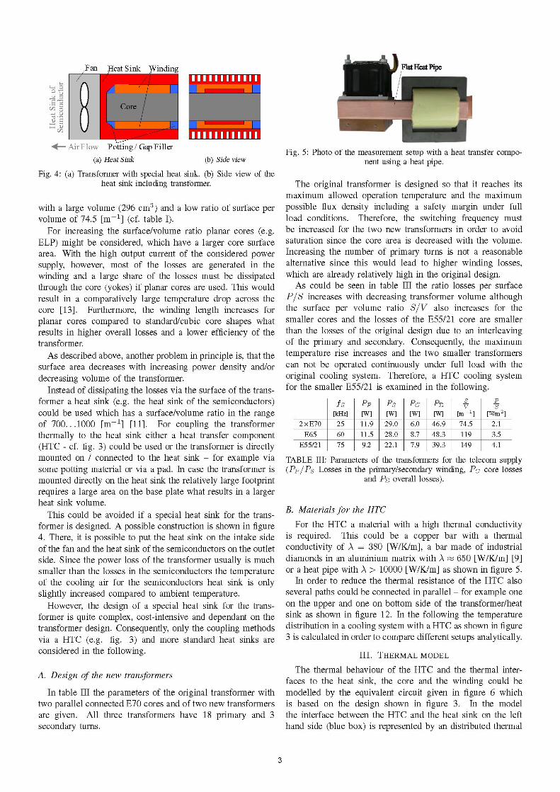
Fig. 4: (a) Transformer with special heat sink. (b) Side view of theheat sink including transformer.
with a large volume (296 cm3) and a low ratio of surface pervolume of 74.5 [m-1] (cf. table I).
For increasing the surface/volume ratio planar cores (e.g.ELP) might be considered, which have a larger core surfacearea. With the high output current of the considered powersupply, however, most of the losses are generated in thewinding and a large share of the losses must be dissipatedthrough the core (yokes) if planar cores are used. This wouldresult in a comparatively large temperature drop across thecore [13]. Furthermore, the winding length increases forplanar cores compared to standard/cubic core shapes whatresults in higher overall losses and a lower efficiency of thetransformer.As described above, another problem in principle is, that the
surface area decreases with increasing power density and/ordecreasing volume of the transformer.
Instead of dissipating the losses via the surface of the trans-former a heat sink (e.g. the heat sink of the semiconductors)could be used which has a surface/volume ratio in the rangeof 700... 1000 [m-1] [11]. For coupling the transformerthermally to the heat sink either a heat transfer component(HTC - cf. fig. 3) could be used or the transformer is directlymounted on / connected to the heat sink - for example viasome potting material or via a pad. In case the transformer ismounted directly on the heat sink the relatively large footprintrequires a large area on the base plate what results in a largerheat sink volume.
This could be avoided if a special heat sink for the trans-former is designed. A possible construction is shown in figure4. There, it is possible to put the heat sink on the intake sideof the fan and the heat sink of the semiconductors on the outletside. Since the power loss of the transformer usually is muchsmaller than the losses in the semiconductors the temperatureof the cooling air for the semiconductors heat sink is onlyslightly increased compared to ambient temperature.
However, the design of a special heat sink for the trans-former is quite complex, cost-intensive and dependant on thetransformer design. Consequently, only the coupling methodsvia a HTC (e.g. fig. 3) and more standard heat sinks areconsidered in the following.
A. Design of the new transformers
In table III the parameters of the original transformer withtwo parallel connected E70 cores and of two new transformersare given. All three transformers have 18 primary and 3secondary turns.
Fig. 5: Photo of the measurement setup with a heat transfer compo-nent using a heat pipe.
The original transformer is designed so that it reaches itsmaximum allowed operation temperature and the maximumpossible flux density including a safety margin under fullload conditions. Therefore, the switching frequency mustbe increased for the two new transformers in order to avoidsaturation since the core area is decreased with the volume.Increasing the number of primary turns is not a reasonablealternative since this would lead to higher winding losses,which are already relatively high in the original design.As could be seen in table III the ratio losses per surface
P/S increases with decreasing transformer volume althoughthe surface per volume ratio S/V also increases for thesmaller cores and the losses of the E55/21 core are smallerthan the losses of the original design due to an interleavingof the primary and secondary. Consequently, the maximumtemperature rise increases and the two smaller transformerscan not be operated continuously under full load with theoriginal cooling system. Therefore, a HTC cooling systemfor the smaller E55/21 is examined in the following.
fs Pp PS PC PE v s[kHz] [W] [W] [W] [W] [m- 1] [WI/m2 ]
2xE70 25 11.9 29.0 6.0 46.9 74.5 2.1E65 60 11.5 28.0 8.7 48.3 119 3.5
E55/21 75 9.2 22.1 7.9 39.3 149 4.1
TABLE III: Parameters of the transformers for the telecom supply(PP8PS Losses in the primary/secondary winding, Pc core losses
and PE overall losses).
B. Materials for the HTC
For the HTC a material with a high thermal conductivityis required. This could be a copper bar with a thermalconductivity of A = 380 [W/K/m], a bar made of industrialdiamonds in an aluminium matrix with A - 650 [W/K/m] [9]or a heat pipe with A > 10000 [W/K/m] as shown in figure 5.
In order to reduce the thermal resistance of the HTC alsoseveral paths could be connected in parallel - for example oneon the upper and one on bottom side of the transformer/heatsink as shown in figure 12. In the following the temperaturedistribution in a cooling system with a HTC as shown in figure3 is calculated in order to compare different setups analytically.
III. THERMAL MODEL
The thermal behaviour of the HTC and the thermal inter-faces to the heat sink, the core and the winding could bemodelled by the equivalent circuit given in figure 6 whichis based on the design shown in figure 3. In the modelthe interface between the HTC and the heat sink on the lefthand side (blue box) is represented by an distributed thermal
3

Pw E FW 5. 0
Rth,W m
Rth,B -RW Q
T Rth,B Rth,B
Heat RSink TA
tTIA
Lore: Yoke - Middle Leg - Yoke
Fig. 6: Distributed thermal model of the cooling system shown infigure 3 with the heat sink on the left hand side, a gap between heatsink and transformer and the transformer with winding on the right
hand side.
network with thermal resistances per unit length. The thermalconductivity between the HTC and the heat sink is describedby Rth,B-H and the conductivity of the HTC itself by Rth,B.The temperature distribution in this area could be calculated byusing transmission line equations (lossy lines without energystorage) what results in the following differential equation(O < X < IHS):
d2PHTC (X)dx2
THTC(X) = - PHTC(X)R&h,BdR + THS
with the inital conditions
0
(PC + Pw)
PHTC = PC + PW (4)
Between the heat sink and the transformer is a small gapwhich could be used for interconnecting the semiconductorsmounted on the heat sink and for the outlet of the air. This gapcould be omitted for the sake of an increased thermal couplingdue to a reduced length of the HTC and a direct thermalcoupling of the core to the heat sink in case the transformeris neither at the outlet nor the intake side of the fan and thespace is not needed for interconnections.
In the gap the temperature distribution in the HTC is givenby (IHS <X < IHS + IG):
THTC = Rth,B HS (Pc +Pw) + THTC(IHS)tBIHS
with
IG = Length of gap [in],
what results in a linear temperature gradient.On the outer parts of the transformer the HTC is only
coupled to the yoke of the core. There, the heat flux couldbe calculated by solving the following ODE: (IHS+IG < X <IHS+IG+lC,Y and IHS+IG+IC-IC,Y <X < IHS+IG+IC):
dx3 PHTC(X)
(3)
(th,B+ th,C) d_RI dxPHTC(X)-th,B-C
Rth,C PC(5)
th,B-Crx
THTC = -J PHTCRth,B + THTC(lo)
with the ICS (cf. fig. 7):(IHS+IG < X < IHS+IG+IC,Y):
PHTC (lo) = -(Pc + Pw)PCq(10) = 0and with
PHTC(X) = Power through HTC at x [W]Rth,H-A = Thermal R of heat sink [K/W]Rth,B-H = Thermal R: HTC - heat sink [A
RLh B Thermal R of HTC [K/W/m]THS = Temperature heat sink [0C]
THTC = Temperature HTC [°C]IHS = Length: HTC-heat sink interfacePC = Losses in the core [W]Pw = Losses in the windings [W].
(IHS+IG+IC-IC,Y < X < IHS+IG+IC):
[7W/rn]
L[m]
PHTC (lo)
PCq (lo)
dx2 PHTC(l0)and with
Rth,B-C-I
In this approach it is assumed that the heat is only dissipatedvia the heat sink and that the base plate of the heat sink isapproximately isothermal due to its high thermal conductivity.With the solution of the differential equation the temperaturedistribution in the HTC could be calculated by
0
0
0
Thermal R: HTC - core [K/W/'m]?th,C = Thermal R of core [K/W]IC,y = Length: HTC-yoke interface [in]
IC = Length: HTC-core interface [in]1w = Length: HTC-winding interface [in]10= IHS + IG or
IHS+IG+IC-IC,Y,
(PC+Pw) Rh RRth B Hcosh RthBX
slnh,-~~ th,B-sinRhhBH
Rth,B-H
where x must be shifted by IHS+IG for the left and by IHS+IG+ IC-IC,Y for the right yoke. The initial conditions atthe border between the yoke and the middle leg where thewinding is located are dependent on the differential equationfor the middle leg. Thus, the constants for the solutions of the
4
HTC bridging the GapInterface: between Transformer
HTC -Heat sink and Heat Sink
B Rth Rth,BG Rth,BD = =
RthBRPHTC(X)th,B-H
PHTC(O)PHTC(IHS)
THTC(X)

PW.g (X) = 0
PHTC(X1 ) PHTC(X1 +)P]o (X1 ) =P1% (X1 +)
PWdg (X2 ) = 0
PHTC, (X2 -) =PHTC (X2 +)PCor (X2 -) =PCor (X2 +)
dPCo(X) d=PCor(x) d dPCP,,, (x)
dx dx dx dx + 1c
XI XI X3 rI Middle Leg
Yo kte P/9 ,
~~~~~~ ~ ~ ~ ~~~" (I
,,I (X. xP ,,(,P",0 d2~~~~~~
Fig. 7: Initial conditions/constraints for the differential equations ofthe temperature distribution in the HTC.
differential equations in the three areas: yoke-leg-yoke mustbe calculated together.
In the middle leg heat is transferred to the HTC by the coreat the bottom side and by the winding at the top side. Theresulting equations are (IHS+IG+IC,Y < X < IHS+IG+IC-IC,Y):
dx2 PHTC(X)
d
dx2PHTC(X)
d PHTC (X)
d2PCq (X)dx2
PHTC(x) ( lt, Rth,B +
+ R/l.' +th,B-W
PCq A + Pwq I
th,B-C th,B-W
=dPcq (X) + ()+ PC+PWdx dx IC 1wIPHTCRth,B + PcqRth,C
th,B-C
THTC ]- PHTCRth,B + THTC(l1)
with the ICS:(IHS+IG+IC,Y < X < IHS+IG+IC-IC,Y):
HTC Winding x
Heat ( Outside
Primary ATp,
C q R~~~~~~~~~th,I
Seconday n 7jRthASecondary . Te
[or
-0
Fig. 8: Heat flow in the winding from the single layers to the HTCvia the insulation (Rth,I).
A. Temperature drop across winding/core
So far only the temperature drop from the heat sink tothe thermal interface of the winding and the core has beenconsidered. The temperature drop within the winding and thecore has been neglected and is calculated in the following.
In a foil winding the heat generated in the single layersflows from one layer via the insulation to the next layer untilit reaches the interface: winding-HTC if in the worst case itis assumed that all losses are dissipated via the HTC and theheat sink.The temperature drop within the copper layers is very small
compared to the drop in the insulation. Therefore, it isneglected in the following. Furthermore, it is assumed thata thermally conductive adhesive tape like BondPlyTM [10] isused for insulating the layers (cf. Rth,I in 8). This reducesthe thermal resistance between the layers significantly. Basedon the mentioned assumptions the temperature drop ATWdgacross the winding could be calculated by [4]
ATwdg = ATpri +ATSecPNr
=Rth,l V NprV 1 pr
E(: NSec ) )
NVecPWq(ll) = 0
PWq(l2) = 0
PHTC(IV-) = PIPCq(lv-) = P(
dx cq)x=x11-d PHTC(X)
~~x 12-
and with
Rth,B-WRth,W
d.
with
HTC(lV+)cq(lv+)
IPcq (X)IxI x=ll+
d Pcq() +cdx X=12+ I
Thermal R: HTC - winding [K/W/m]
Thermal R of winding [K/W]
l1 = IHS+IG+IC,Y
12 = IHS+IG+IC-IC,Y.For calculating the temperature distribution within the HTC
and the transformer, first the differential equations for the twoyokes and the middle leg must be solved. In the second stepthe 13 unknown constants in the solutions must be calculatedby applying the initial conditions/constraints given in theequations 5 and 6 (cf. fig. 7).
Rdijl= [K/W]th
RCIlWdg1WPpri Losses in primary winding [W]PSec Losses in secondary winding [W]
Npri/N.ec Number of primary/secondary turns,
where aI, is the thermal conductivity and d, the thickness ofthe insulation layer. There, the thermal conductivity of thewinding in the direction of the copper layers is much higherthan the conductivity across the insulation, i.e. the equivalentcircuit for the winding has an anisotropic thermal conductivity.
For the parameters of the E55/2 1 core in the telecomsupply and BondPlyTM as insulation a worst case maximumtemperature drop of 19.1°C results in the winding if no heatis dissipated via the surface of the winding. The real valueis lower since a share of the losses is also dissipated via thesurface.The temperature drop in the core is given by
ATcore L2 PLeg
5
(7)

HTC Size THTC TW RemarkCu 3x 17 102.7°C 115.6°CCu 3x 17 1070C 1160C MeasurementH-P 3x17 50.6 C 61 C A 5000K/WH-P 3x 17 53°C 65°C Measurement
TABLE IV: Calculated and measured temperatures for a copper HTCand a heat pipe.
Fig. 9: Heat flow in the magnetic core - improved by copper layer.
with
Rth,Leg = Thermal resistance of the core leg[K/W]PLeg = Heat generated in the heat flow path,
where the heat flow path starts in the middle of the outerleg (where the two E-core halves are joint together) and runsthrough the yoke to the middle leg/HTC. Due to the relativelylow thermal conductivity of ferrite the drop in the core couldbe high (25°C for the E55/21) if is assumed that no heat isdissipated via the surface. In order to reduce the temperaturedrop across the core thin (1mm) copper foils are bonded onthe top side of the core where also the HTC is located (cf. fig.9). This reduces the temperature drop to 5.4°C which couldbe calculated by
RthLegRthCUA\TcOre,cu R / PLeg (8)tanh R,
th,Leg
with
Rth,Leg = Per unit thermal R of the core leg[K/W]
Rth,CU = Per unit thermal R of the copper layer[K/W],
resulting from the mentioned transmission line approach formodelling the temperature distribution.
IV. RESULTS FOR DIFFERENT HTCs
With the equations derived in the preceding sections thetemperature distributions in transformers with HTC could becalculated. In order to validate the results a test setup as shownin fig. 10(a) has been built and the temperature distributionhas been measured with thermocouples and an infrared camera(cf. fig.10(b)).The heat was generated with a copper foil winding whose
connectors were heated so that approximately no heat wasdissipated via the connectors. Moreover, the transformer wasput in a thermally isolated housing so that only a small amountof heat is dissipated directly via the transformer surface.
_ 100-
90-
a 80-
0 70-
60-
o 50-u 40-
ce 30-
. 20-
E- 10-
Measurements
HEeft Sjl1k IHS
TW(x)
Tc(xI
THTC(X)/:LL~IG IC Y
PHTC(X),.
0 1 2 3 4
" IC IC.Y
6 7 8 9 10
x [cm]
Fig. 11: Distribution of temperature and losses for a HTC made ofcopper for 40°C ambient temperature.
In table IV the resulting analytical and measured values fora HTC made of copper and of a heat pipe are given. There,the calculated values agree very well with the measured ones.This could be also seen in figure 11 where the calculatedtemperature/power flow distribution for the test setup withcopper HTC is plotted.
With the validated equations the temperature distributionfor different possible setups for the telecom power supply arecalculated. The results for the E55/21 core with a 17mm wideHTC in different configurations are given in table V. There,the thickness of the HTCs is either constantly 3mm or 3mmin the region of the winding and 5mm outside this region.
For the calculations it has been assumed that the twotransformers of the lOkW system are connected to the heatsink shown in figure 10(a) which has a thermal resistance ofRth,HS = 0.31 K/W, a volume of 0.12dm3 and a cooling sys-tem performance index (CSPI) of 26.7 [W/K/dm3]. The CSPItells what cooling system power density could be achievedand is independent of system efficiency and temperature levels[11].Due to the relatively high thermal resistance of the copper
HTC the high temperature drop of 82K across the HTCresults and causes a maximum winding interface temperatureof > 1600C. The temperature of the heat sink THS = 64°C re-sults with the total losses of app. 2 x40W for both transformersand the thermal resistance of the heat sink. This temperatureis independent of the HTC since it is always assumed that all
(b) Thermopicture
Fig. 10: (a) Setup for temperature measurement with optimisedcopper heat sink [11] and (b) related measurement with thermo
camera.
Size THTC Rth,HTCCu 3x17 146.0°C 149.6 C 146.4 C 2.65 K/W
2xCu 3x17 107.1 C 109.4 C 107.5 C 1.67 K/W2xCu 3/5x17 101.2°C 103.5°C 101.6°C 1.53 K/WDia/Al 3x17 114.2°C 119.2°C 114.8°C 1.88 K/W
2 x Dia/Al 3x17 90.1 °C 92.9°C 90.4 C 1.25 K/WDia/Al 3/5 x 17 107.20C 112.1 C 107.8 C 1.69 K/WH-P 3x17 75.3°C 82.3°C 75.7°C 0.88 K/W
TABLE V: Maximum temperatures in the thermal interfaces forHTCs made of copper, diamond in Al-matrix and heat pipe without
temperature drop in the winding/core.
6
7 HeatFlow
/CopperLayer
HTC
(a) Measurement setup
4-0 4-- ......--- ...... -- .......... 1. L:. . ---

,Fan Heat SinkAWinding
HTC
Fig. 12: Parallel connection of two HTCs for double sided cooling.
the losses are dissipated via the heat sink.If two HTCs are connected in parallel as shown for example
in figure 12 the thermal resistance between the transformer andthe heat sink is halved. Therefore, the overall thermal resis-tance and the peak temperature of the transformer decreasessignificantly. This could be seen in row 1 and 2 of table Vwhere the values for one and two parallel connected HTC aregiven.
A. Comparison
In the original transformer a maximum temperature ofapproximately 1290C was measured in the winding at fullload. Taking the values given in table V and consideringthe temperature drop within the winding/core which are ap-proximately 190C (cf. preceding paragraph) an equal or evenlower maximum temperature could be achieved either withtwo copper / diamond + AL-matrix HTCs in parallel or oneHTC made of heat pipe. There, it is assumed as worst casethat no heat is dissipated via the surface of the transformer.
With the heat pipe solution a relatively low thermal resis-tance could be achieved what results in an maximum possibleoutput power of 6.5kW per transformer / 13kW for theconverter and a maximum power density of 55kW/dmi3 forthe transformer including heat sink.
In table VI the volume, the power density, the surface pervolume and the efficiency for the transformer with E70 coreand for the one with E55/21 core, HTC and heat sink are given.The power density of the new solution is more than 3 timeshigher than the power density of the 2xE70 transformer. Bycombining a transformer with a HTC and heat sink much morecooling surface per volume could be realised what results in asmaller possible overall volume for a given amount of losses.Due to the lower winding length and the reduced core volumealso the efficiency is slightly increased.
In [12] and [13] planar cores with a power density of up to109kW/dmi3 are published. The reasons for the high value arethe lower power level and the relatively low current values.With an increasing power/current level the achievable powerdensity reduces since the volume scales with m3 and thesurface only with m2 so that the heat transfer deteriorates.This could also be seen in [14] where a 50kW transformerwith a power density of 18kW/dmi3 is presented. There, and
Vol r IV V
2xE70 0.29 13.1 74.5 99.0%E55 + HTC + HS 0.118 42.3 365.9
E55 + HP + HS (6.5kW) 0.118 55 365.9 99.0%
TABLE VI: Comparison between E70 and E55 transformer with HTCand heat sink (HS).
(a) Middle leg of transformer (b) Equivalent circuit
Fig. 13: (a) Middle leg of a transformer with a HTC in the window.(b) Simplified magnetic equivalent circuit of the Transformer.
in the two other publications the additional volume of theheat sink, fan or convection which is required for cooling thetransformer is not considered in the power density calculation.If only the transformer volume is considered a power densityof 77.3kw/dm3 results for the design with the E55 core.
V. EDDY CURRENTS IN THE HTC
Since the HTC, made of thermally highly conductive mate-rial which are usually also very good electrical conductors, isplaced close to the magnetic core/winding one has to consideralso eddy currents/losses in the HTC which are induced by theAC magnetic fields. The losses, however, are relatively smallsince the magnetic field close to the ferrite core is quite small(usually some IOOA/m for transformers in the kW range). Thereason for this is the high permeability of the core and the lowpermeability (,u - 1) of the air and the HTC - confer to fig.13(a) where a section of the middle leg of a transformer isshown (the HTC is placed in the window). Due to the differentpermeabilities, the magnetic flux mainly flows through the coreand not through the air and/or the HTC.
This could be also seen in the magnetic equivalent circuitwhich is shown on the right hand side of fig. 13(b). There, thewinding is represented by a voltage source and the core and theair/HTC are modelled by magnetic reluctances/resistors. Thecurrent generated by the voltage source, which is equivalent tothe magnetic flux, will mainly flow through the resistor withthe lower resistance value (= magnetic core) as the magneticflux does in the ferrite core.
In case the core would be removed, the path with highpermeability/low magnetic reluctance is missing and the fluxwill mainly flow through the air/HTC. This would result inhigh eddy current losses in the HTC.
Since the run of the magnetic flux lines usually is 3dimensional an accurate analytic calculation of the losses
(a) 3D FEM model (b) Induced eddy currents
Fig. 14: (a) 3D model used in the FEM-simulation. (b) Result of theFEM simulation with magnetic flux density in the core and current
density in the HTC.
7
O. p4.~
(

Fig. 15: Application of the indirect air cooling in a 5kW telecompower supply with lOkW/dm3 and 1U height.
in the HTC is almost impossible and very time consuming.Based on some assumptions the field could be simplified toan ID geometry (e.g. Dowell approach) and the losses cananalytically approximated. The result for a transformer as usedin the power supply (- IA magnetising current) is in the rangeof 10-20mW.
In case a FEM simulation of the set-up is performed also3D effects for calculating the eddy currents can be considered.During a variety of simulations (cf. for example fig. 14 /110mW losses in the HTC) it turned out that the additionallosses in the HTC, including 3D-effects, are in the range of50-150mW depending on the geometric arrangement of thecomponents. Compared to the overall losses in the transformerof approximately 40W and the transferred power of 5kW theseadditional losses can be neglected.
So far only transformers have been considered. There, theair gap between the two halves of the E-cores is usuallyvery small - ideally equal to zero. Thus, also the magneticreluctance of the air gap and the fringing field of the gap arevery small and can be neglected. In case of inductors either acore material with a low permeability (e.g. metal powder) or acore with a distinct air gap is used. There, the magnetic fieldclose to the core/air gap is much larger than the field closeto the ferrite core of the transformer. Consequently, the eddycurrent losses in the HTC will increase significantly.On the other hand the eddy currents in the HTC attenuate
the magnetic field outside the core/air gap. This reduces thelosses in the inductor windings. The total losses, however,usually increase since the HTC is placed very close to thecore/air gap. In order to limit the additional losses the HTChas to be designed in such a way that the eddy currents arelimited - for example the distance between the HTC and theair gap could be increases by a recess.
VI. CONCLUSION
For increasing the power density of converter systemsthe volume of the magnetic components must be decreasedamongst others. Since the component's efficiency usually isnot increasing very much while reducing the volume the heattransfer to the ambient must be improved in order to limit thetemperatures.
In this paper a cooling concept which couples a transformerwith a heat sink by a heat transfer component made of copper,diamond + Al-matrix or a heat pipe is presented and comparedwith traditional forced air cooling systems. Based on thisconcept a transformer for a 5kW telecom power supply isredesigned what results in an three times increase of thepower density of the transformer and an improved efficiency.With a HTC made of heat pipes a maximum power densityof 55kW/dmi3 for the transformer with cooling system areachieved without cooling via the surface of the transformer.
Based on the indirect air cooling system a redesign of thetelecom supply has been performed, where also the topologyand the switching frequency have been optimised. There,a power density of l0kW/dmi3 and an overall height of 1U(40mm) could be achieved (cf. figure 15).
REFERENCES
[1] J.T. Strydom, "Electromagnetic Design of Integrated Resonator-Transformers," Ph.D. Thesis, Rand Afrikaans University, South Africa,2001.
[2] I.W. Hofsajer, "On electromagnetic Integration in Hybrid ElectronicStructures," D. Eng. Thesis, Industrial and Electronics Research Group,Faculty of Engineering, Rand Afrikaans University, May 1998.
[3] J. Biela and J.W. Kolar, "Analytic Design Method for (Integrated-)Transformers ofResonant Converters using Extended Fundamental Fre-quency Analysis," Proceedings of the 5th International Power ElectronicsConference (IPEC), Niigata, Japan, April 4 - 8, 2005.
[4] J. Biela, "Optimierung des elektromagnetisch integrierten Serien-Parallel-Resonanzkonverters mit eingeprdgtem Ausgangsstrom," Ph.D.Thesis, Eidgenossische Technische Hochschule - ETH Zurich, Switzer-land, 2006.
[5] J. Minibock, J.W. Kolar and H. Ertl, "Design and Experimental Analysisof a 10kW Dual 400V/48V Interleaved Two-Transistor DC/DC ForwardConverter System Supplied by a VIENNA Rectifier I," Proceedings of the41st Power Conversion / Intellegent Motion / Power Quality Conference,Nuremberg, Germany, June 6 - 8 (2000).
[6] W.G. Odendaal und J.A. Ferreira, "A Thermal Modelfor High-FrequencyMagnetic Components," IEEE Transactions on Industry Applications,Vol. 35, Issue 4, July-Aug, 1999, pp. 924-931.
[7] M. Jackob, "Heat Transfer," John Wiley & Sons, New York, London1949.
[8] A. van den Bossche und V.C. Valchev, "Inductors and Transformers forPower Electronics," CRC Taylor & Francis Group, London, New York,2005.
[9] U. Drofenik and J.W. Kolar, "Analyzing the Theoretical Limits of ForcedAir-Cooling by Employing Advanced Composite Materials with ThermalConductivities >400W/inK," Proceedings of the 4th International Con-ference on Integrated Power Systems (CIPS'06), Naples, Italy, June 7 -
9, 2006.[10] http://www.bergquistcompany.com[11] U. Drofenik, G. Laimer und J.W. Kolar, "Theoretical Converter Power
Density Limits for Forced Convection Cooling," Proceedings of theInternational PCIM Europe 2005 Conference, Nuremberg, Germany,June 7-9, pp. 608-619.
[12] W.A. Roshen, R.L. Steigerwald, R.J. Charles, W.G. Earls, G.S. Claydonand C.F. Saj, C.F., "High-Efficiency, High-Density MHz Magnetic Com-ponents for Low Profile Converters," IEEE Transactions on IndustryApplications, Vol. 31, Issue 4, July-Aug., 1995, pp. 869-878.
[13] W.G. Odendaal, J. Azevedo, G.W. Bruning and R.M. Wolf, "A High-Efficiency Magnetic Component with Superior Caloric Performance forLow-Profile High-Density Power Conversion," IEEE Transactions onIndustry Applications, Vol. 40, Issue 5, Sept.-Oct. 2004, pp. 1287-1293.
[14] M. Pavlovsky, S.W.H. de Haan and J.A. Ferreira, "Design for betterThermal Management in High-Power High-Frequency Transformers,"Conference Record of the Industry Applications Conference, 2005, 40thIAS Annual Meeting, Vol. 4, 2-6 Oct, pp. 2615-2621.
8