potential use of ground penetrating radar in highway rock...
TRANSCRIPT

Proceedings of the 51st Annual Highway Geology Symposium, Seattle, Washington, Aug. 29 - Sep. 1, 2000, pp. 249-259.
Highway Rock Cut Stability Assessment in Rock Masses Not Conducive to Stability Calculations
NORBERT H. MAERZ
Department of Geological Engineering, University of Missouri-Rolla, 1006 Kingshighway,
Rolla, MO, 65409-0660 USA
Key Terms: Rock Cuts, Slope Stability, Discontinuities.
Abstract Ensuring the stability of highway rock cuts requires an evaluation of the structure of the rock. Failures usually initiate and follow pre-existing discontinuities rather than break through intact rock. Rock determined to be loose or with the potential for failure must be removed or restrained in some way. Analytical calculations of potential instability can range from limiting equilibrium analysis to numerical modeling. In many terrains the discontinuities are oriented in such a way that they contribute to create wedge, planar, or toppling failures. These are then relatively easy to analyze. In other terrains, most notably flat lying sedimentary rock with vertical jointing, the predominant failure mechanism tends to be raveling, which is typically not conducive to calculation. This paper describes some of the techniques currently used for stability assessment, as well as speculating on future trends in analysis and data acquisition.
Introduction The safety and convenience of the motoring public demands that highway rock cuts be made safe. Catastrophic failures of rock cuts can result in property damage, injury, and even death. Highways impeded by even small spills of rock material are in addition an inconvenience for motorists (Figure 1). Ensuring the stability of highway rock cuts, whether new or old, requires an evaluation of the structure of the rock. Failures usually initiate and follow pre-existing discontinuities rather than break through intact rock. Thus it is the nature of the discontinuities (joints, fractures, bedding planes, faults, and other breaks in the continuity of the rock) and not of the intact rock that governs the mechanical and hydrological behavior of the rock mass (Figure 2). With a few exceptions, most of the rock masses that engineers deal with are influenced to some extent or another by discontinuities. While the understanding of the mechanical properties of intact, solid rock is well advanced in rock mechanics, the understanding of the fundamental behavior of discontinuous rock is significantly less well developed.
Planar and wedge sliding and toppling analysis and remediation In many terrains the discontinuities are oriented in such a way that they contribute to create wedge, planar sliding, or toppling failures (Figure 3). Franklin and Senior (1997b) report that of

Figure 1. Example of rock failures causing obstructions in roadways
Figure 2. The discontinuous nature of rock masses
Figure 3. Example of wedge, planar, and toppling failures along road cuts.
415 analyzed cases of failure in Northern Ontario, only 33% of failures involved these mechanisms (23% toppling, 8% planar sliding, 2% wedge sliding). These are failures are however easy to analyze, and can range from limiting equilibrium analysis to numerical modeling (Hoek and Bray, 1981; Piteau, 1979c; Piteau, 1979d). The mapping of discontinuity orientations is a requirement, before or after the cut has been exposed (Piteau, 1979a; Piteau, 1979b; Piteau 1979g). Rock determined to be loose with the potential for failure must be removed or restrained in some way (Piteau, 1979e). Prescribed designs for remediation and/or mitigation are easy to find (Brawner, 1994; Konya and Walter, 1991; Piteau, 1979f; Franklin and Senior, 1997a).
Raveling type failure modes In the Northern Ontario study, 65% of the failures were of the �raveling� type (Figure 4). These included raveling (25%), overhang/undercutting failure (15%), ice jacking (14%), and rolling blocks (11%). In other terrains, most notably flat lying sedimentary rock with vertical jointing, where planar and wedge slides are unusually not found, the predominant failure mechanism being of the raveling type is even greater. These raveling failures, whether slow, time-dependent or fast and catastrophic are much more difficult to analyze. Analytical techniques for prediction are non-effective, and remediation judgments are typically made with on-site engineering judgment of an experienced specialist, who must then balance the risk in terms of probability of failure and consequence of failure, against the cost of effective remediation. The use of empirical design and rock mass classification become important (Franklin and Maerz, 1996). Even though no analytical tools are available for this task, other tools are available for the practitioner. One example of this is the use of empirical design and rock mass classification, as for an example the Oregon RHR (Rock fall hazard rating)) system. The Colorado rock fall simulation program (CSRP) can be used to assess the risk of falling, rolling and bouncing rocks, and to design slope angles, breaks, and ditch dimensions to mitigate the consequence of falling, bouncing and rolling rocks. Other new technologies are available to assist in the analysis and design. Imaging software such as WipJoint can be used to analyze the structure and block size of the rock. Computer analysis, using instrumented cameras, using oblique images will in future be able to measure or estimate slope heights, slope angles, loose rock quantities and ditch capacities to help identify optimum remedial measures and help with construction specification quantities.
Empirical Design and Rock Mass Characterization Empirical design is a design methodology that does not use formal design methods, and calculations or analytical equations or modeling or such. Instead it relies on experience and judgment of the engineer. When applied to rock cuts, an experienced engineer with considerable expertise in a particular geological terrain, will be able to use his experience to drive the design But what of the inexperienced engineer, or the experienced engineer in an unfamiliar geological terrain? Clearly the engineer needs to rely on more than his own experience. This is where rock mass classification comes in. Classification is defined as the formal arrangement of attributes in a hierarchy. In the case of rock engineering this means collecting data and classifying the outcrop in some meaningful way, based on parameters that are both easy to measure or classify, and are useful as predictors of rock behavior. Examples of such parameters would include block size and rock strength. The realization of empirical design that uses not only individual experience, but also the cumulative experiences of many comes from the following principles.

Figure 4. Raveling, undercutting, and rolling failures along road cuts.
1. Description of ground quality by a quantitative classification system, based on parameters that are easily and universally measured.
2. Description of ground performance by a formal set of parameters (unsupported stand time,
support requirements, bearing capacity, ease of excavation, etc.).
3. Correlation of the above 2 based on a broad spectrum of case histories, based on local or global experience.
Design schemes like this are common in the mining and tunneling industries, and are described in
Singh and Goel (1999). Examples of such classification systems that include elements of design includes Deere�s RQD (rock quality designation) system (Deere et al., 1969), Franklin�s Size-Strength system (Franklin, 1986), Franklin�s Shale Rating System (Franklin, 1983), Bieniawski�s RMR (rock mass rating) system (Bieniawski, 1984), and Barton Q system (Barton et al., 1974).
In addition there are several schemes for slopes. Romana�s SMR system is for rock slopes, based on Bieniawski�s RMR system (Romana, 1985). The Oregon RHR (rock hazard rating) system is designed specifically for highways cuts ((Pierson and Van Vickle, 1993). The Ontario RHRON (Rock Hazard Rating ONtario) system is a modification of the Oregon system (Franklin and Senior, 1997b).
Basic Rock Mass Classification - RMR Bieniawski�s rock mass rating (RMR) was originally developed for tunneling (Singh and Goel, 1999; Bieniawski, 1998). In this system 5 basic parameters are measured or estimated in the field:
1. Uniaxial compressive strength of the intact rock, 2. RQD (rock quality designation), 3. Discontinuity spacing, 4. Condition (weathering) of the discontinuities, 5. Groundwater conditions.

Each of these parameters is rated with a value typically between 0 to 20, 0 to 15, or 0 to 30 depending on the case. The sum of these 5 ratings is the basic RMR rating, which is an evaluation of rock quality without taking into affect the orientation of the discontinuities. This sum is then modified by a negative rating for discontinuity orientation. Discontinuities are rated as favorable or unfavorable in terms of strike parallel/perpendicular to tunneling direction, dip with/against direction of tunneling, and dip angle. Ratings range between 0 to �12 for tunnels. The final RMR rating is then used to determine both unsupported stand-up time and support requirements, as a function of opening span, based on an empirical database.
Rock Mass Classification Applied to Slopes - SMR Romana�s slope mass rating (SMR) builds on the RMR system by incorporating adjustments to the basic RMR rating (Singh and Goel, 1999):
( ) 4321 FFFFRMRSMR basic +••−= where:
( )( )21 sin1 jsF αα −−=
where αs is the strike of the slope face and αj is the strike of the critical joint (discontinuity) plane, and:
jF βtan2 =
where βj is the joint dip angle with respect to planar failure mode, and F3 is a rating between 0 and �60 based on the relationship between the slope face and the dip of the discontinuity. While these three parameters deal primarily with sliding and toppling failure mechanisms, the F4 parameter is an adjustment factor dealing with the method of excavation (poor blasting �8, normal blasting or mechanical excavation 0, smooth blasting 8, pre-split blasting 10, and natural slopes 11). As with RMR, the SMR value ranges between 0 and 100, and design charts can be used to infer stability, type of failure potential, and a crude estimate of the probability of failure. Suggested support designs are also available.
Rock Mass Classification For Rock Falls � RHR The rock fall hazard rating system (RHR) was designed to proactively address the issue of rock falls for road cuts and rail lines (Pierson and Van Vickle, 1993). The system goes much further than other classification systems, in addition to looking at material properties, taking into account such diverse aspects as rock fall history, volumes of material that might fail, and the capacity of existing mitigation measures to contain that volume of rock, in a quasi-probabilistic manner. In addition, the system is useful as a screening technique, allowing high-risk slopes to be quickly identified by a preliminary rating. The preliminary rating consists of an assessment of the slope into one of three categories, A, B, C (high, moderate, low) for two considerations: 1) Estimated potential for rock fall on roadways, and; 2) Historical rock fall activity. Typically only slopes with preliminary ratings of A are given detailed ratings.
The detailed rating system uses 10 categories with 4 nominal rating criteria and scores, although interpolations of scores between criteria are allowed. The scoring is a power progression, with score y=3X where x is a rating between 1 and 4 and allows scores of 3, 9, 27, and 81 respectively. The following are the categories:
1. Slope height (25, 50, 75, or 100 feet), 2. Ditch effectiveness (good, moderate, limited, or no catchment), 3. Average vehicle risk (vehicle present in rock fall section 25, 50, 75, or 100% of the time), 4. Sight distance (100, 80, 60, or 40% of stopping distance when viewing a 6� object), 5. Roadway width (44, 36, 28, or 20 feet including shoulders), 6. Structural condition discontinuous rock (discontinuous joints- favorable orientation,
discontinuous joints � random orientation, discontinuous joints � adverse orientation, or continuous joint � adverse orientation),
7. Rock friction (rough �irregular, undulating, planar, clay infilling or slickensided), or
6. Structural conditions eroded rock (few differential erosion features, occasional erosion features, many erosion features, or major erosion features),
7. Difference in erosion rates (small, moderate, large � favorable structure, or large � unfavorable structure),
8. Block size/volume of rock fall event (1/3, 2/6, 3/9, or 4/12 ft/cubic yards), 9. Climate and presence of water on slope (low to moderate precipitation; no freezing periods;
no water on slope, moderate precipitation or short freezing periods or intermittent water on slope, high precipitation or freezing periods or continual water on slope, or high precipitation and long freezing periods or continual water on slope and long freezing periods,
10. Rock fall history (few, occasional, many, or constant falls).
All the categories are then added up, and the highest scores are deemed to have the highest priority in terms of remediation.
Rock Mass Classification For Rock Falls � RHRON The rock fall hazard rating system, Ontario, (RHRON) is a modified version of the RHR system. It attempts to address the overemphasis on high slopes and large volumes that occur as a result of the power relationship between rating and score (Franklin and Senior, 1997a). In Ontario, with its relatively lower slopes than locations like Oregon, the RHR system was just not sensitive enough. In addition, five new parameters were added, and several parameters were re-defined. The basic formulation for RHRON is:
( )36
1004321(%) ∗+++= FFFFRHRON
where: F1=Magnitude: �How much rock is unstable?�, F2=Instability: �How soon or often is it likely to come down?�, F3=Reach: �What are the chances of this rock reaching the highway?�, F4=Consequence: �How serious are the consequences of the blockage?� For the preliminary screening, each of these F factors is directly rated on a scale of 0 to 9. For the detailed rating, each of these F factors are calculated from a number of individual ratings also on a scale of 0-9:

( )3
)4321 RRRF ++=
( )6
)65411912 RRRRRRF ravelling+++++=
( )6
)86511912 RRRRRRF sliding+++++=
( )
6)107411912 RRRRRRF erosion
+++++=
( )
419161343 RRRRF +++=
( )
3)1918174 RRRF ++=
where: R1=History of rock falls R2=Volume of the largest potential rock fall R3=Volume of total potential rock fall R4=Face irregularity R5=Face looseness R6=Joint orientation/persistence R7=Rock intact strength R8=Rock joint shear strength R9=Block size R10=Slake durability R11=Water table height R12= Slope height R13=Crest angle R14=Ditch and shoulder width R15=Ditch capacity R16=Overspill potential R17=Average vehicle risk R18=Decision sight distance R19=Available paved width R20=Remediation cost
Not all ratings (R) are used in all cases and some ratings are used for different purposes entirely such as calculating cost-benefit ratios.

Rolling and Bouncing Rock - CRSP Having identified slopes with significant failure potential, the consequences of the failure must be evaluated. One aspect of this evaluation has to be an analysis of the kinetics of the bouncing and rolling rock. Will the falling rock reach the highway? What effect will slope angles have on this? Will the rock bounce or roll into the catchment ditch and out the other side? One way to assess this is to do some tests to evaluate this. If the roadway below a slope is closed, it is a simple matter to select 100 typical broken rock fragments and roll them from the top of the slope and record how far towards the road they travel. Of course it is not always possible to close the road below. An interesting alternative is the Colorado rock fall simulation program (CSRP) (Figure 5). This program uses slope and rock geometry and material properties, calculating falling rock bounce height, velocity and travel distance. While this can be used to predict the amount of road material that will reach the road, its most useful application is probably to help with design of slope angles, break in slope angles and, ditch geometry. Because rounded rocks rolling gather a great deal more energy than angular blocks sliding, the results, in terms of predicting the amount of rock reaching the roadway, should be used with caution. In addition, CRSP requires the input of a number of coefficients, which are best input empirically, based on calibrating with actual bouncing and rolling tests.
Figure 5. CRSP simulation for 100 blocks 0.4� in diameter bouncing and rolling down a slope to a roadbed. The simulation reveals that for the original geometry (left) 14 blocks reach the road surface; if the slope is cut back (center), 2 blocks reach the road surface, and if a ditch is put in place (right), no blocks reach the road surface.
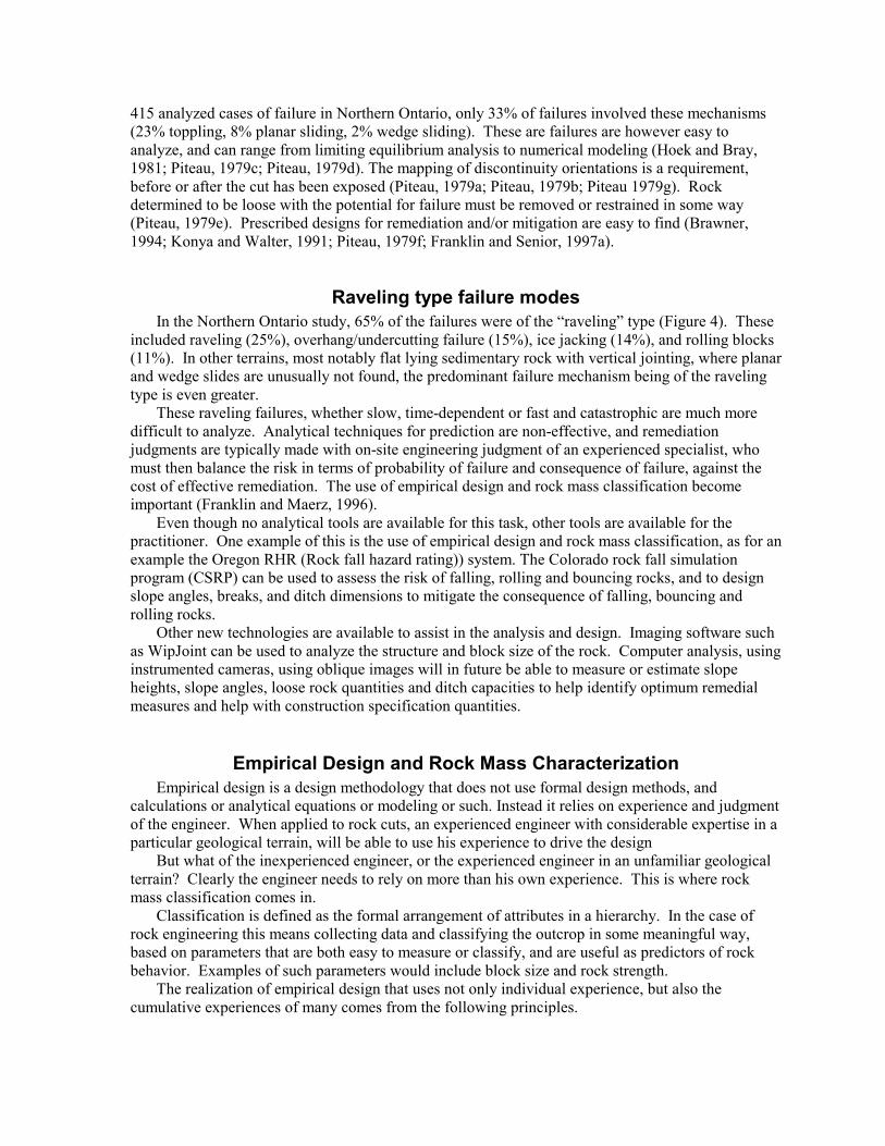
Automated Measurements - WipJoint A cursory survey of the different ratings of RHRON shows that a significant number of the parameters upon which these ratings are based are items where quantities are measured or estimated. Examples of these include slip heights, ditch capacities, block sizes, block volumes, and face irregularities. Some of these items are conducive to automated measurements such as can be done using image analysis (Franklin and Maerz, 1988; Maerz et al., 1997). An example of an image analysis package that does exactly this is WipJoint, designed to measure blocks size and joint fabric images of rock cuts (Figure 6).
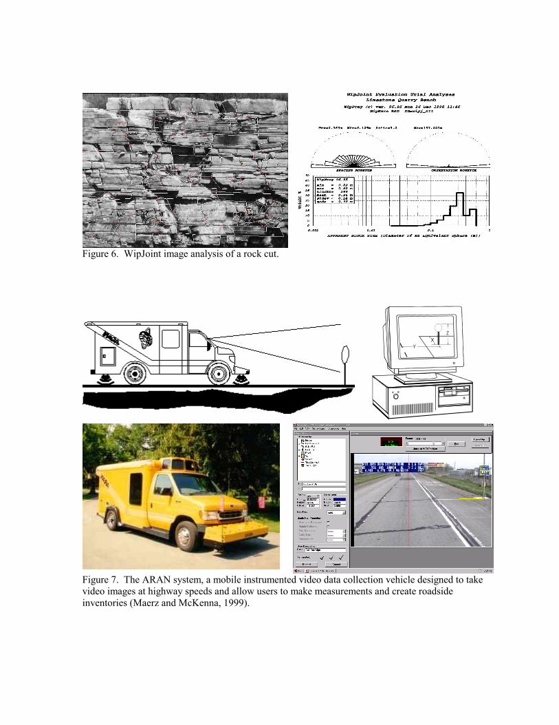
Figure 6. WipJoint image analysis of a rock cut.
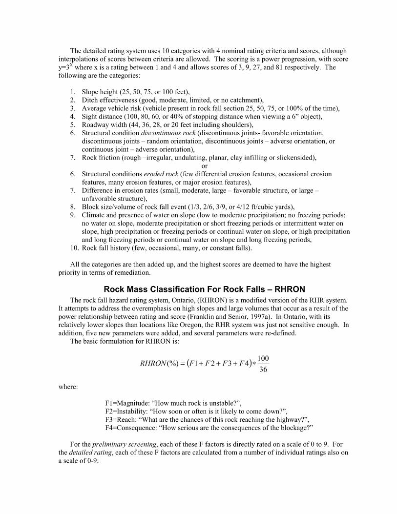
Figure 7. The ARAN system, a mobile instrumented video data collection vehicle designed to take video images at highway speeds and allow users to make measurements and create roadside inventories (Maerz and McKenna, 1999).

Future Trends - Rapid Screening and Mobile Automated Measurements Future trends in automated measurements of rock cuts may come in the form of a mobile data acquisition system. An example of such a system is the ARAN (Automatic Road Analyzer) Surveyor System (Figure 7) (Maerz and McKenna, 1999). This system was designed to allow measurements of object dimensions, and inventorying of those dimensions. A user identifies objects and distances to be measured using mouse clicks on a computer monitor showing the video taped images. The computer then makes all necessary calculations, possible because each video frame has an associated data set that corresponds to the camera position, attitude, speed, and orientation. This type of data acquisition would open entirely new possibilities with respect to collecting data for rock cuts. In the first place, although video logging is not entirely new, it allows initial screening of the cuts. Often engineers spend all too much time screening road cuts, deciding which need to be further evaluated and which do not, rather than focusing on those that are clearly in need of work A further benefit is that in addition to being a screening tool, this would provide a permanent record of the condition of the road cuts at a given point in time. Second, the measurement capabilities can be used to measure estimated volumes of rock, slope heights, slope angles, ditch capacities and land and shoulder widths. Finally hard copies of the video images can form �working diagrams� (Figure 8), complete with GPS (global positioning system) coordinates for establishing correct locations.
Figure 8. Simulated images demonstrating the potential to develop mobile vision based data acquisition systems for rudimentary measures such as slope heights, slope angles, loose rock quantities and ditch capacities
References BARTON, N. M., LIEN, R., AND LUNDE, J, 1974, Engineering classification of rock masses for the
design of tunnel support: Rock Mechanics 6, pp.189-236. BIENIAWSKI, Z. T., 1984. Rock Mechanics Design in Mining and Tunneling: A. A. Balkema. BIENIAWSKI, Z. T., 1998. Design principles and methodology for excavations in geologic media: 49th
Highway Geology Symposium Proceedings and Field Trip Guide, Prescott, Arizona, Sept. 10-14, 1998, pp. 1-13.
BRAWNER, C. O., 1994. Rockfall Hazard Mitigation Methods. Participant Workbook: FHWA Report � FHWA-SA-93-085.
DEERE, D. U., MERRITT, A. H., AND COON, R. F., 1969. Engineering Classification of in Situ Rock: Air Force Systems Command, Kirtland Air Force Base, Report AFWL-64-144.
FRANKLIN, J. A., 1983. Evaluation of shale�s for construction projects � An Ontario shale rating system: Research Report RR229, Ontario Ministry of Transport and Communication, 99 pp.

FRANKLIN, J. A., 1986. Size-strength system for rock characterization: Proceedings of the Symposium of Rock Characterization to Mine Design, American Society of Mining Engineers Annual Meeting, pp. 11-16.
FRANKLIN, J. A., AND MAERZ, N. H., 1996. Empirical design and rock mass characterization: Proceedings of the FRAGBLAST 5 Workshop on Measurement of Blast Fragmentation, pp. 193-201.
FRANKLIN, J. A., MAERZ, N. H., AND BENNETT, C. A., 1988. Rock mass characterization using photoanalysis: Int. J. of Min. and Geol. Eng., v 6, pp. 97-112.
FRANKLIN, J. A., AND SENIOR, S. A., 1987a. Outline of RHRON, the Ontario rockfall hazard rating system: Proceedings International Symposium on Engineering Geology and The Environment, Athens, Greece, pp. 647-656.
FRANKLIN, J. A., AND SENIOR, S. A., 1987b. Rockfall Hazards � Strategies for detection, assessment, and remediation: Proceedings International Symposium on Engineering Geology and The Environment, Athens, Greece, pp. 657-663.
HOEK, E., AND BRAY, J., 1981. Rock Slope Engineering: The Institution of Mining and Metallurgy, 358 pp.
KONYA, C.J., AND WALTER, E.J., 1991. Rock Blasting and Overbreak Control: FHWA Report � FHWA-HI-92-001.
MAERZ, N. H., BENNETT, C. P., DONY, B. A., 1987. Microcomputer image analysis of rock fabric: 1st. Can. Symp. on Microcomputer Applications to Geotechnique, Regina, Canada, pp. 269-275.
MAERZ, N. H., AND MCKENNA, S., 1999. Mobile highway inventory and measurement system. Transportation Research Record No. 1690, pp. 135-142.
PIERSON, L. A., AND VAN VICKLE, R., 1993, Rockfall Hazard Rating System � Participants� Manual: FHWA Report � FHWA-SA-93-057, 102 pp.
PITEAU, D. R., 1979a, Engineering geology considerations and basic approach to rock slope stability analysis for highways. Part A., Rock Slope Engineering Reference Manual: FHWA Report � FHWA-TS-79-208, 78 pp.
PITEAU, D. R., 1979b, Methods of obtaining geological, structural, strength and related engineering geology data. Part B, Rock Slope Engineering Reference Manual: FHWA Report � FHWA-TS-79-208.,147 pp.
PITEAU, D. R., 1979c, Approach and techniques in geological structural analysis. Part C, Rock Slope Engineering Reference Manual: FHWA Report � FHWA-TS-79-208
PITEAU, D. R., 1979d, Slope stability analysis methods. Part D, Rock Slope Engineering Reference Manual: FHWA Report � FHWA-TS-79-208.
PITEAU, D. R., 1979e, Rock slope stabilization, protection and warning-instrumentation measures and related construction considerations. Part E, Rock Slope Engineering Reference Manual: FHWA Report � FHWA-TS-79-208.
PITEAU, D. R., 1979f, Blasting for rock slopes and related excavation considerations. Part F, Rock slope Engineering Reference Manual: FHWA Report � FHWA-TS-79-208.
PITEAU, D. R., 1979g, Description of detail line engineering geology mapping method. Part G, Rock slope Engineering Reference Manual: FHWA Report � FHWA-TS-79-208, 29 pp.
ROMANA, M, 1985. New adjustment ratings for application of Bieniawski classification to slopes: International Symposium on the Role of Rock Mechanics, Zacatecas, pp. 49-53.
SINGH, B. ADND GOEL, R. K., 1999. Rock Mass Classification. A Practical Approach in Civil Engineering: Elsevier, 267 pp.