post combustion carbon capture using ... library/research/coal/cross...raghava r. kommalapati, phd,...
TRANSCRIPT

Raghava R. Kommalapati, PhD, PE, BCEE Director, NSF CREST Center for Energy & Environmental Sustainability
Professor, Department of Civil and Environmental Engineering Prairie View A&M University
POST COMBUSTION CARBON CAPTURE USING POLYETHYLENIMINE (PEI) FUNCTIONALIZED
TITANATE NANOTUBES (DE-FE0023040)
2014 NETL HBCU/UCR Joint Kickoff Meeting, October 28 and 29, 2014 Project Manager: Dr. Jessica Mullen

Co-Investigators
Ziaul Huque1,2 , Xinhua Shen1,** Kyoungsoo Lee1
1 NSF CREST Center for Energy & Environmental Sustainability, 2 Department of Mechanical Engineering,
Prairie View A&M University
**Current Address: Department of Earth Science, University of Northern Iowa.
10/28/2014 2

Center for Energy & Environmental Sustainability
• NSF CREST Center funded in October 2010 • $5M for 5 years • 3 research focus areas in addition to
education and outreach – Biofuels, wind energy and Energy &
Environmental Sustainability – 6 faculty members, 3 post-docs, and 8 grad
10-12 undergrad students per year – Helping to enhance the research capabilities
and infrastructure
10/28/2014
3
Overview
• Introduction • Post-Combustion Capture • Objectives • Projects Goals and Tasks • Timelines and Outcomes • Participants • Facilities and Equipment
10/28/2014 4
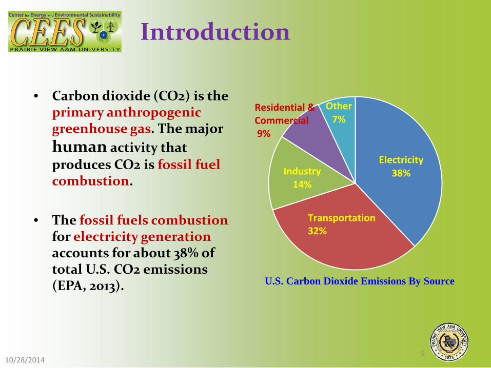
• Carbon dioxide (CO2) is the
primary anthropogenic greenhouse gas. The major human activity that produces CO2 is fossil fuel combustion.
• The fossil fuels combustion for electricity generation accounts for about 38% of total U.S. CO2 emissions (EPA, 2013).
Electricity 38% Industry
14%
Other 7%
U.S. Carbon Dioxide Emissions By Source
Transportation 32%
Residential & Commercial 9%
10/28/2014 5
Introduction
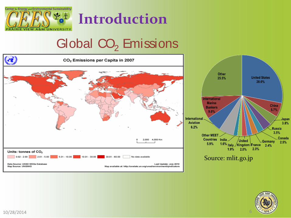
Source: mlit.go.jp
10/28/2014 6
Introduction
Global CO2 Emissions

Introduction
Total CO2 emission
Power-plant CO2 emission
Source: ohioenvironmentallawblog.com
Source: petrolog.typepad.com 10/28/2014 7
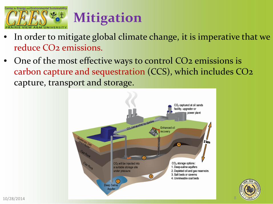
Mitigation • In order to mitigate global climate change, it is imperative that we
reduce CO2 emissions. • One of the most effective ways to control CO2 emissions is
carbon capture and sequestration (CCS), which includes CO2 capture, transport and storage.
10/28/2014 8

• CCS contributes one-sixth of the total CO2 emissions reductions required by 2050 and 14% of the cumulative emissions reductions through 2050 against business-as-usual scenario (International Energy Agency, 2014).
• The figure below indicates the economically efficient mix of CO2 mitigation measures to stabilize atmospheric CO2 concentrations at 550 ppm on using MiniCAM. (Logan et al., 2007)
Carbon Capture and Sequestration
10/28/2014 9

• The current major CO2 capture technologies include oxy-combustion capture, pre-combustion capture, and post-combustion capture (Lee et al., 2012; Spigarelli and Kawatra, 2013).
• Each have advantages and limitations • Post-combustion technologies are the focus here
Carbon Capture and Sequestration
10/28/2014 10

CO2 Capture Technologies
• Oxy-combustion capture
• Post-combustion capture
• Pre-combustion capture
Source: Bellona Environmental CCS http://bellona.org/ccs/technology/capture/oxyfuel.html 10/28/2014
11

Post Combustion CO2 Capture Technologies
• Post-combustion carbon capture is especially desirable due to its potential to retrofit existing power plants with reasonable cost. A simplified schematic of post-combustion carbon capture for a coal-fired power plant is shown as following:
• CO2 is captured after the flue gases are cleaned up by Electro Static Precipitator (ESP) and Flue Gas Desulfurization (FGD).
Combustion
Fuel
Air
Flue Gas CO2 + N2 CO2 capture
Low CO2 Flue Gas
ESP FGD
10/28/2014 12
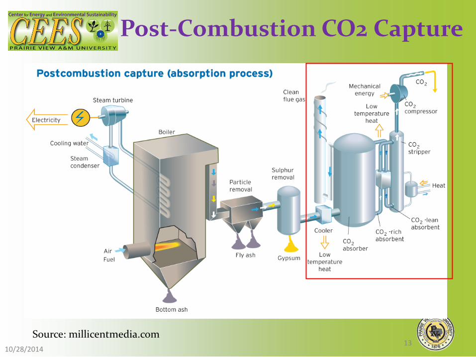
Post-Combustion CO2 Capture
Source: millicentmedia.com 10/28/2014
13
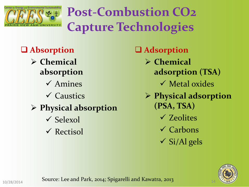
Post-Combustion CO2 Capture Technologies
Absorption Chemical
absorption Amines Caustics
Physical absorption Selexol Rectisol
Adsorption Chemical
adsorption (TSA) Metal oxides
Physical adsorption (PSA, TSA) Zeolites Carbons Si/Al gels
Source: Lee and Park, 2014; Spigarelli and Kawatra, 2013 10/28/2014 14

Post-Combustion CO2 Capture Technologies Continued..
Membrane Organic membrane
Polysulphone Polyamide Cellulose
derivatives Inorganic membrane
Metallic Ceramics
Enzymatic membrane
Cryogenics
Others Chemical looping CO2 hydrate Electrochemical
pump Microbial/Algae
Source: Lee and Park, 2014; Spigarelli and Kawatra, 2013 10/28/2014 15
Post-Combustion CO2 Capture Technologies
• In post-combustion capture, CO2 is removed from the flue gas after the combustion of the fossil fuel with air (DOE, 2010), and the flue gas usually has low CO2 content and low pressure (about 1 bar).
• Current technologies for post-combustion CO2 capture focus mainly on solvent-based absorption, however, the low pressure of the power plant flue gas would result in additional cost for CO2 compression, transportation and storage.
• Other disadvantages of absorption include degradation in an oxidizing atmosphere, more energy intensive during regeneration, has limited CO2 loading capacity, and are corrosive with foaming and fouling characteristics (Sreenivasulu et al., 2015). 10/28/2014
16

Post-Combustion CO2 Capture Technologies Continued…
• To solve the challenge of processing a large-volume, low-pressure flue gas, many recent researchers have focused on the separation of CO2 using porous solid adsorbents. The high surface areas and specific adsorption sites of porous materials make them good candidates for application in CO2 capture.
• Nanoporous materials are porous materials with pore diameter of 100 nanometers or less, their high surface area and light weight make them promising for carbon capture application.
10/28/2014 17

Post-Combustion CO2 Capture Technologies Continued..
• Significant focus on nanoporous materials functionalized with amines for carbon capture due to their high selectivity and efficiency for carbon capture from flue gas.
• Synthesizing highly efficient amines-functionalized nanoporous materials is still a big challenge; more efforts need to be put on the investigation of optimal parameters for synthesizing economic and effective nanomaterial for CO2 capture..
10/28/2014 18

Relevant Literature • Only one study (Liu et al. 2012) was obtained from the
literature that was relevant to our project • The use of modified protonated titanate nanotubes
(PTNTs) in combination with PEI was examined • The larger specific surface area (320.4 m2/g) and pore
volume (1.07 cm3/g) of PTNTs proved to beneficial to the introduction of PEI with little hindrance, thereby, guaranteeing a high loaded capacity.
• The functionalized PTNTs with 50 wt.% PEI loading exhibited a high adsorption capacity of 130.8 mg/g-sorbent at 100⁰C .
10/28/2014 19

Objectives
The specific objectives of the proposed research are: • Establish a knowledge base on the synthesis of TiO2
nanotubes and adsorption characteristics of Polyethylenimine (PEI) and also the various protocols available for the impregnation of PEI.
• Develop optimized protocols for synthesis of TiO2 nanotubes impregnated with PEI.
• Characterize the impregnated nanotubes and use it for refining the parameters for synthesis such as temperature, concentration and time.
10/28/2014 20

Objectives (continued)
• Develop computational fluid dynamic (CFD) simulations of the carbon capture process in the reactor to optimize the reactor conditions for high carbon capture efficiency.
• Demonstrate the efficiency of impregnated TiO2 tubes for carbon capture under various environmental conditions such as temperature and concentration,
• Establish a validated CFD model and a standard operating procedure for carbon capture using PEI impregnated TiO2 nanotubes.
10/28/2014 21

Project Tasks
• The proposed research will be carried out in a series of 7 tasks:
10/28/2014 22

Project Task 1.0
Task 1.0 – Project management and planning • A Project Management Plan (PMP) was completed and
submitted to NETL, we will manage and report on activities in accordance with the plan.
10/28/2014 23

Project Task 2.0
Task 2.0 – Literature review and identification of materials and protocols • A comprehensive literature review on (i) current
nanomaterial synthesis and technology for carbon capture as well as (ii) current reactor designs and optimizations that are being used will be conducted to facilitate the material synthesis and reactor design and fabrication.
• Special attention will be placed to identify innovative methods to efficiently and economically synthesize the materials and design the carbon capture reactors.
10/28/2014 24
Project Task 3.0
Task 3.0 – Synthesis of PEI impregnated Titanate nanotubes • A novel nanomaterial with the unique porous properties of
Titanate nanotube and the adsorption features of impregnated polyethylenimine (PEI) will be developed to efficiently capture CO2 from the flue gas effluent from fossil energy power generation.
• Specifically, Polyethylenimine (PEI) functionalized Titanate nanotube will be synthesized using impregnation method.
• The synthesis process includes two subtasks: (i) Preparation of Titanate nanotube, (ii) Polyethylenimine (PEI) functionalization.
10/28/2014 25

(i) Preparation of Titanate nanotube • Hydrothermal reaction method will be used to prepare
Titanate nanotube. • The hydrothermal method is a widely used technique for
preparation of Titanate nanotubes. • A typical hydrothermal synthesis procedure:
Project Task 3.0 (continued)
NaOH solution
TiO2 nanopowder DI
H2O HCl
anneal for 48 hours DI
H2O
dry for 24 hours Titanate
nanotube
Wash
10/28/2014 26

(i) Preparation of Titanate nanotube (continued)
• The reaction environments such as temperature, solvent concentrations, hydrothermal duration, and the subsequent washing times, as well as washing acid concentration are critical factors that affect the characteristics of Titanate nanotubes products.
• The above parameters will be tested to acquire the optimal materials for the Polyethylenimine (PEI) functionalization step.
Project Task 3.0 (continued)
10/28/2014 27
(ii) Polyethylenimine (PEI) functionalization • Polyethylenimine (PEI) functionalization will be
conducted using impregnation method, which is commonly used for amine functionalization.
• Several reaction conditions such as temperature, concentration and other parameters will be studied in order to try to optimize this functionalization procedure.
Project Task 3.0 (continued)
10/28/2014 28
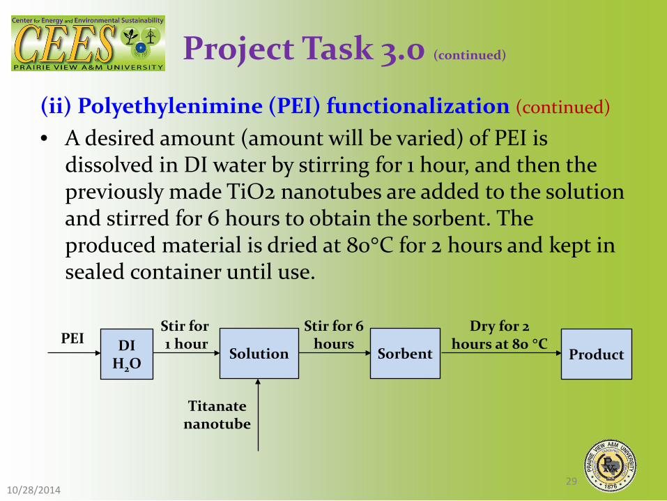
(ii) Polyethylenimine (PEI) functionalization (continued)
• A desired amount (amount will be varied) of PEI is dissolved in DI water by stirring for 1 hour, and then the previously made TiO2 nanotubes are added to the solution and stirred for 6 hours to obtain the sorbent. The produced material is dried at 80°C for 2 hours and kept in sealed container until use.
Project Task 3.0 (continued)
Stir for 6 hours PEI
Solution
Stir for 1 hour
Sorbent
Dry for 2 hours at 80 °C DI
H2O
Titanate nanotube
Product
10/28/2014 29
Task 4.0 – Characterization of the PEI impregnated Titanate nanotubes and optimization of synthesis protocol • The thermal stability of the synthesized material will be
studied using Thermogravimetric analysis (TGA) to determine weight differences associated with thermal changes.
• The influence of PEI loading on CO2 adsorption performance will be measured by TGA.
• The material morphologies will be observed using transmission electron microscopy (TEM), and the structure of crystal phases will be analyzed by X-ray diffraction (XRD).
Project Task 4.0
10/28/2014 30
Project Task 4.0 (continued)
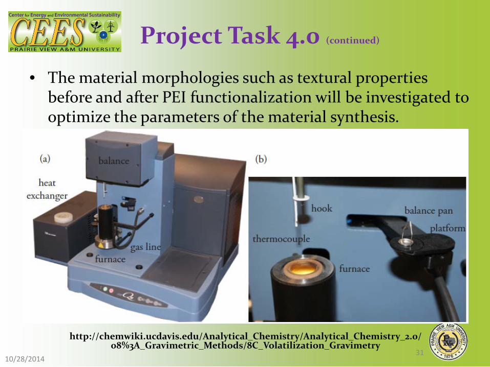
• The material morphologies such as textural properties before and after PEI functionalization will be investigated to optimize the parameters of the material synthesis.
http://chemwiki.ucdavis.edu/Analytical_Chemistry/Analytical_Chemistry_2.0/08%3A_Gravimetric_Methods/8C_Volatilization_Gravimetry
10/28/2014 31

Project Task 4.0 (continued)
Transmission Electron Microscopy • The material morphologies will
be observed using transmission electron microscopy (TEM).
• Figure shows the the FEI Tecnai G2 F20 ST TEM in the Microscopy and Imaging Center at Texas A&M University.
http://microscopy.tamu.edu/instruments
10/28/2014 32
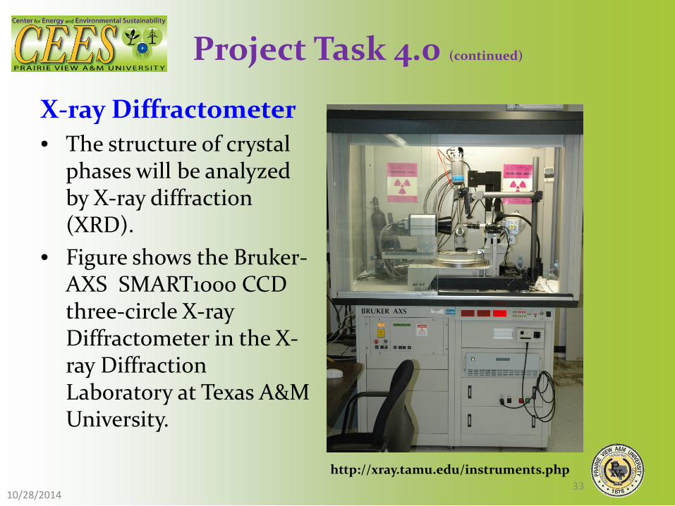
Project Task 4.0 (continued)
X-ray Diffractometer • The structure of crystal
phases will be analyzed by X-ray diffraction (XRD).
• Figure shows the Bruker-AXS SMART1000 CCD three-circle X-ray Diffractometer in the X-ray Diffraction Laboratory at Texas A&M University.
http://xray.tamu.edu/instruments.php
10/28/2014 33

Task 5.0 – CFD modeling of the carbon capture reactor • Computational fluid dynamics (CFD) simulations will be
performed using several commercial CFD codes for post combustion CO2 capture process using the porous media concept to model the developed nanomaterial used in this study.
• Good predictions of the pressure drop and the mass transfer characteristics in the reactor are critical for scaling up the reactors and the validated CFD simulations will help in predicting the optimum design parameters for large scale applications.
Project Task 5.0
10/28/2014 34

• By modeling the exhaust gas flow, the pressure drop and the uniformity of flow through the porous media can be determined. To simulate the CO2 adsorbing reactor using CFD analysis, porous media for fixed-bed reactors will be considered.
Project Task 5.0 (continued)
10/28/2014 35

<Mesh model>
Porous interface
<Geometry model> <Mesh model>
Flue gas
Porous media
10/28/2014 36
CFD Modeling : Porous Media
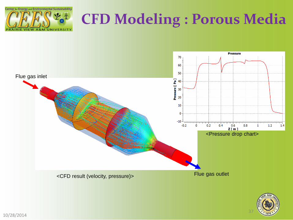
Flue gas inlet
Flue gas outlet <CFD result (velocity, pressure)>
<Pressure drop chart>
10/28/2014 37
CFD Modeling : Porous Media

Task 6.0 – Experimental testing of the carbon capture reactor • The capture of carbon dioxide from the carbon dioxide and
nitrogen gas mixture will be tested in a customized fixed-bed CO2 adsorbent reactor.
• The CO2 adsorption capacities at various pressure and temperature will be tested and calculated.
• In the desorption phase, the temperature is increased, and the gas flow will be changed to N2.
• The adsorption and desorption cycle will be conducted multiple times to test the performance of prepared material.
Project Task 6.0
10/28/2014 38

Project Task 6.0 (continued)
CO2 adsorbent reactor
Gas heater CO2 N2
MSC MSC
T GC T
Gas Chromatography
• A Shimadzu GCMS-QP2010 Ultra gas chromatograph with mass spectrometer will be used to measure the flue gas content.
10/28/2014 39

Task 7.0 – Standard operating procedure for lab scale carbon capture reactor using PEI impregnated TiO2 nanotubes and validated CFD Model • Final optimized parameters for fabricating TiO2
nanotubes using hydrothermal method and further functionalization by Polyethylenimine (PEI) using impregnation method
• CFD model simulations will be validated using the experimental results and optimized reactor parameters will be established.
• An optimized and functioning CFD model as well as a standard operating procedure for designing, fabricating and operating a carbon capture reactor will be developed.
Project Task 7.0
10/28/2014 40

Project Timetable
Task Name 10/2014- 03/2015
04/2015- 09/2015
10/2015- 03/2016
04/2016- 09/2016
10/2016- 03/2017
04/2017- 09/2017
Task 1
Task 2
Task 3
Task 3.1
Task 3.2
Task 4
Task 5
Task 6
Task 7
10/28/2014 41

Relevance & Outcomes/Impacts
• A unique and Innovative Method. • Two materials (TiO2 and Polyethylenimine (PEI) that are
commonly used for many purposes separately but in this study we are impregnating TiO2 nanotubes with PEI to provide a highly selective nano- porous material with a very large surface area to capture carbon.
• The study will optimize the procedures for synthesizing the nanotubes and the impregnation protocols and develop standard operating procedures for carbon capture at different temperatures and concentrations.
• A successful outcome from this proposed study will provide a very high efficiency and low cost method to capture CO2 from effluents of advanced fossil energy systems.
10/28/2014 42

Relevance & Outcomes/Impacts
• The proposed study will be conducted at Prairie View A&M University, a Historically Black College/University (HBCU).
• Roy G. Perry College of Engineering will have an opportunity to enhance our research capabilities into energy research and particularly into carbon capture technologies.
• This will also enhance our educational training infrastructure to include these topics into our newly established Energy Engineering minor.
• This will have impact on many students from the underrepresented group here on PVAMU campus.
• The proposed research will train and support at least 2 undergraduate and one to two graduate students to engage in the challenging energy research.
10/28/2014 43

Roles of Participants
• Prof. Raghava R. Kommalapati (Ph.D., Louisiana State University, 1995) will serve as Principal Investigator for this project and he will coordinate all aspects of the research project.
• Dr. Kommalapati is the Director of NSF CREST Center for Energy & Environmental Sustainability (CEES) and Professor of Civil and Environmental Engineering at Prairie View A&M University.
• Dr. Kommalapati has many years of experience in environmental engineering research, particularly in the area of air quality, air-fog interactions and environmental impact of various energy technologies.
10/28/2014 44

Roles of Participants
• Co-PI, Dr. Xinhua Shen (Ph.D., Colorado State University, 2011) was a post-doctoral researcher at PVAMU and currently an assistant professor at University of Northern Iowa.
• She has two patents on developing porous materials for high temperature gas purification, including "Method of preparing iron-aluminum based metal compound microporous filter element, and its application", "Porous catalytic filtering metal material and its preparation".
• Dr. Shen will participate in material synthesis, material characterization and experimental testing to optimize CO2 capture.
10/28/2014 45

Roles of Participants
• Co-PI, Dr. Ziaul Huque (Ph.D., Oregon State University, 1991) is a professor of Mechanical Engineering at Prairie View A&M University.
• Dr. Huque has many years of experiences in computational fluid dynamics (CFD) simulations. Dr. Huque will oversee the CFD simulation.
• Dr. Kyoungsoo Lee (Ph.D., Inha University, South Korea 2009) is a Post-Doctoral Researcher in CEES, and has many years' experiences of using CFD to develop the aerodynamic analysis on the wind energy and structural area.
• Dr. Lee will work on the CFD simulation to optimize the operational parameters and conditions.
10/28/2014 46

Roles of Participants
• Dr. Akhil Kadiyala, recently joined CEES as a post-doctoral researcher and will participate in the project to coordinate the laboratory experiments
• One (possibly two) graduate student and two undergraduate students at Prairie View A&M University will participate in the planned literature review, material synthesis, material characterization and experimental testing.
10/28/2014 47

Facilities and Other Resources
• Material synthesis and characterization will be performed in the laboratories of the Center for Energy & Environmental Sustainability and Civil & Environmental Engineering.
• Part of the material characterization will be conducted in the labs available in Department of Mechanical Engineering,
• CFD simulations and experimental tests will be conducted using the computing facilities in the Center for Energy & Environmental Sustainability.
• A Total of more than 5,000 sq ft of laboratory space is available for this research. Two technicians are also available in the College of Engineering for any assistance needed with material synthesis.
10/28/2014 48

Equipment
• The primary pieces of equipment that will be used for this study include;
• Thermogravimetric Analyzer (TGA Q500 TGA with Auto sampler made by TA Instruments)
• Transmission Electron Microscopy (TEM) • X-ray diffraction (XRD) instrument • Shimadzu GCMS-QP2010 Ultra gas chromatograph with
mass spectrometer . – TGA and GC-MS are available in the Roy G. Perry College of
Engineering. The PIs have ongoing relationship with several researchers at our system university, Texas A & M University and they have access to TEM and XRD and will be available for our use at nominal cost.
10/28/2014 49

Equipment
10/28/2014 50

Other Equipment
• High performance 48 noted cluster in the center for CFD simulations.
• 4 – 16 nodes HP workstations for computing
10/28/2014 51
Other Equipment (continued)
• Agilent 1200 series HPLC • Dionex ICS 5000, Ion chromatograph • Shimadzu TOC-L Total Organic Carbon Analyzer • Shimadzu UV-1800 UV Spectrophotometer • Thermo-Orion 720A pH Meter • Ohaus AS200 Analytical Balance • Fisher Scientific FS140H Tabletop Ultrasonic Cleaner • Thermolyne cimarec 3 HP47135 stirrer • Thermolyne 1300 Furnace • Water purification system.
10/28/2014 52

Questions?
10/28/2014 53