position switches and multiple limit switches...led indicator seals made of nbr a-8 position...
TRANSCRIPT

EN
Position Switches and Multiple Limit Switches

2
Internationally successful – the EUCHNER company
EUCHNER GmbH + Co. KG is a world-leading company in the area of industrial safety technology. EUCHNER has been developing and producing high-quality switching sys-tems for mechanical and systems engineering for more than 60 years.The medium-sized family-operated company based in Leinfelden, Germany, employs around 750 people around the world.
18 subsidiaries and other sales partners in Germany and abroad work for our inter-national success on the market.
Quality and innovation – the EUCHNER products
A look into the past shows EUCHNER to be a company with a great inventive spirit.We take the technological and ecological challenges of the future as an incentive for extraordinary product developments.
EUCHNER safety switches monitor safety doors on machines and installations, help to minimize dangers and risks and thereby reliably protect people and processes. Today, our products range from electromechanical and electronic components to intelligent integrated safety solutions. Safety for people, machines and products is one of our dominant themes.
We defi ne future safety technology with the highest quality standards and reliable technology. Extraordinary solutions ensure the great satisfaction of our customers. The product ranges are subdivided as follows:
Transponder-coded Safety Switches Transponder-coded Safety Switches with guard locking Multifunctional Gate Box MGB Access management systems (Electronic-Key-System EKS) Electromechanical Safety Switches Magnetically coded Safety Switches Enabling Switches Safety Relays Emergency Stop Devices Hand-Held Pendant Stations and Handwheels Safety Switches with AS-Interface Joystick Switches Position Switches
Headquarters in Leinfelden-Echterdingen
madeinGermany
Logistics center in Leinfelden-Echterdingen
Production location in Unterböhringen

Contents
3157836-01-03/18
Position switches Chapter A
Position switches according to EN 50041 Chapter B
Multiple limit switches, trip rails and trip dogs Chapter C
Position Switches and Multiple Limit Switches
AB
C

4

A-1
A
Position Switches
A

A-2

Contents
A-3
A
General information A-4
Precision single hole fixing limit switches A-9
With reed contact A-10
With snap-action switching element A-16
With slow-action switching element A-23
Precision single limit switches A-25
Design N01 A-26
Design NB01 A-31
Design SN01 A-32
Design N1A A-34
Design N10 A-38
Design N11 A-39
Inductive single limit switches A-41
Design ENA A-42
Design ESN A-43
Accessories A-44
Round connector M12 A-44
LED function display A-47
Cable glands A-47
Additional products A-47
Appendix A-48
Terms and explanations A-48
Item index A-50
Position Switches

A-4
Position Switches
Subject to technical modifications; no responsibility is accepted for the accuracy of this information.
General information
Precision single limit switches
EUCHNER precision single limit switches are technically precise command switches, which have been developed on the basis of practical require-ments in close collaboration with machine tool manufacturers.The use of high-quality materials, the interplay of sophisticated technol-ogy and practically oriented design guarantee operation under even the toughest conditions.EUCHNER precision single limit switches are used for positioning and controlling machines and in industrial installations.The different designs, with a choice of five different types of plunger, and easy adjustability from longitudinal to transverse actuation offer the user a broad range of individual applications.
Precision single hole fixing limit switches with reed contact or snap-action switching element
EUCHNER precision single hole fixing limit switches are technically sophis-ticated command switches, which have been proving their reliability, day in and day out, for decades in harsh industrial applications.These mechanically actuated precision single hole fixing limit switches are IP 67 rated and are entirely maintenance-free.EUCHNER precision single hole fixing limit switches feature a thread on the upper part and can thus be inserted or screwed through the mounting hole either from the cable end or from the actuator end. Setting the position of the operating point opposite the part of the machine to be sensed is easy with this thread.The compact overall size and the round design allow installation directly at the sensing points. This feature dispenses with the complicated levers or linkages associated with a high level of design complexity and expense.
Inductive single limit switches
Inductive single limit switches are used for positioning and control in all areas of mechanical and systems engineering. Inductive single limit switches are used for automation tasks in machinery in the wood, textile and plastics industries.Due to their non-contact and thus wear-free principle of operation, induc-tive single limit switches are insensitive to heavy vibration, heavy soiling and have an above average mechanical life even in aggressive ambient conditions.Interchangeability with mechanical single limit switches means that it is possible to straightforwardly modify machines. The switches can therefore be retrofitted on existing machine installations to take full advantage of the benefits of non-contact switches.

A-5
Position Switches
Subject to technical modifications; no responsibility is accepted for the accuracy of this information.
A
Switching elements with reed contact
1) A snap-action contact element has a switching contact that opens and closes independently of the approach speed during actuation.
2) A slow-action contact element has a switching contact that opens and closes depending on the approach speed during actuation.
Reed contact
The reed contact comprises two ferromagnetic contacts in a glass bulb. When the reed contact is placed in a magnetic field, the contacts adopt opposite polarities and are closed.For series EGT with reed contact.
Changeover contact with snap-action function
Snap-action switching element 1) with single gap and three connections.For series EGT with snap-action switch and series N01, NB01, SN01 with soldered connection.
Snap-action switching element 1) with one normally open contact (NO) and one normally closed contact (NC)
With double gap and electrically isolated switching bridge. The two moving contacts are electrically isolated from each other. Switching element with four connections.For series SN01 with soldered connection and series N1A, N10, N11.
Mechanical switching elements
Safety switching element with slow-action switching contact 2)
With one positively driven contact and double gap. Switching contact with two connections.For use in single limit switches with safety function.For series NB01 with safety function and series N1A with safety function.
Safety switching element with snap-action switching contact 1)
With one positively driven contact and one NO contact. Double gap and electrically isolated switching bridge. Switching contact with four connections.For use in single limit switches with safety function.For series N1A with safety function.
Solenoid
A-6
Position Switches
Subject to technical modifications; no responsibility is accepted for the accuracy of this information.
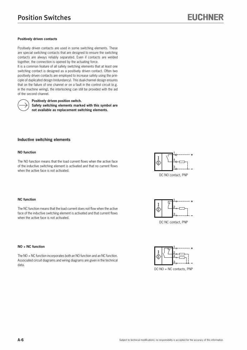
Inductive switching elements
NO function
The NO function means that the load current flows when the active face of the inductive switching element is activated and that no current flows when the active face is not activated.
NO + NC function
The NO + NC function incorporates both an NO function and an NC function.Associated circuit diagrams and wiring diagrams are given in the technical data.
NC function
The NC function means that the load current does not flow when the active face of the inductive switching element is activated and that current flows when the active face is not activated.
DC NO contact, PNP
1
4
3
1
2
3
DC NC contact, PNP
DC NO + NC contacts, PNP
1
4
3
2
Positively driven contacts
Positively driven contacts are used in some switching elements. These are special switching contacts that are designed to ensure the switching contacts are always reliably separated. Even if contacts are welded together, the connection is opened by the actuating force.It is a common feature of all safety switching elements that at least one switching contact is designed as a positively driven contact. Often two positively driven contacts are employed to increase safety using the prin-ciple of duplicated design (redundancy). This dual-channel design ensures that on the failure of one channel or on a fault in the control circuit (e.g. in the machine wiring), the interlocking can still be provided with the aid of the second channel.
Positively driven position switch. Safety switching elements marked with this symbol are
not available as replacement switching elements.

A-7
Position Switches
Subject to technical modifications; no responsibility is accepted for the accuracy of this information.
ASeals
EUCHNER uses high-quality and proven acrylonitrile-butadiene rubber (NBR) for all seals and sealed areas. This material is resistant to oils, greases, fuels, hydraulic fluids and most known cooling lubricants. Moreover, NBR possesses high mechanical strength over a wide temperature range and so it is perfectly suitable for the highly stressed diaphragm seal, which separates the plunger compartment and the interior of the switch. The material of the diaphragm seal is a key criterion for the quality, mechanical life and precision of the EUCHNER precision multiple limit switches. The same material is used for the cover seal and the cable entry.Seals made of Viton or silicone are available on request for special applications.
Exterior diaphragm
To provide protection against resinous cooling lubricants and against the penetration of very small particles, e.g. saw dust, graphite and glass dust, and to provide protection against freezing in the low temperature range, a series with an exterior diaphragm is available. The exterior diaphragm provides additional sealing of the plunger outside the housing. The plunger guides in the housing are thus reliably protected from the penetration of the cooling lubricant. Plunger sticking is prevented, and the replacement of the switch or plunger is unnecessary. Technical data for this series: see page A-37.
Layout
The die-cast aluminum housings for the EUCHNER single limit switches have been proven in even the harshest conditions with their high strength and resistance to corrosion.They do not require a protective paint finish, but can be painted at any time without prior treatment.Depending on the design, the hardened plungers made of stainless steel run precisely in either the anodized guide bore in the housing or in a sintered bronze sleeve. These maintenance-free sliding elements make a key contribution to the reliability and correct operation of the switches. Even beyond the guaranteed mechanical life.
Precision single limit switches
Plunger
Cable entry
Switching element
LED indicator
Seals made of NBR

A-8
Position Switches
Subject to technical modifications; no responsibility is accepted for the accuracy of this information.
Cable connection
EUCHNER position switches are tested to degree of protection IP 67 in accordance with IEC 60529. In order to obtain this degree of protection, only high-quality metal cable glands with a captive sealing ring are used. A selection for different cable diameters is listed on page A-47.
Adjustability
On the chisel plungers and the roller plungers (normal and extended) the approach direction can be changed by 90° at any time. After unscrewing the locking pin, the plunger can be rotated by 90°.
LED function display
If required, the EUCHNER single limit switches of design N1A can be equipped with an LED function display (AC/DC 10 - 60 V or AC 110/230 V, color red). Built-in electronic regulation ensures that the luminosity remains constant independent of the voltage applied.
EUCHNER
LE060 rt12-60V
X1
X2

A-9
Position Switches
Subject to technical modifications; no responsibility is accepted for the accuracy of this information.
A
Single hole fixing limit switches – cylindrical design
The round design with simple, single-hole assembly allows installation of the command switches directly at the scanning points. Exact adjustment is permitted by means of the precision metric thread. The limit switches with inert gas contact (reed contact) can be operated up to a water column pressure of 30 meters with degree of protection IP 68.
Features
Six basic types M12 x 1 to M18 x 1.5 Housing of nickel-plated brass or stainless steel Mechanical life up to 30 million operating cycles Degree of protection IP 68/IP 67 Operating point accuracy ± 0.01 mm max. With hard-wired cable or with M12 plug connection Temperature range -30 °C to +120 °C

A-10
Position Switches
Subject to technical modifications; no responsibility is accepted for the accuracy of this information.
Precision single hole fixing limit switches
With reed contact and protective diode Plunger material stainless steel Any installation position
Design EGT12, M12 x 1, dome plungerConnecting cable, double insulated
BUBN
BUBN
Never switch incandescent lamps. Not even for test purposes.
Single hole fixing limit switches must not be used as an end stop.
Dimension drawings
Design EGT12, M12 x 1, dome plungerConnecting cable, double insulated
6
4
4
SW17
2,5
±0,
3
0,8
-0,6
0,5
M12x1R2,5
3461
12,6
5,4
End
posi
tion
Diffe
rent
ial t
rave
l
Ope
ratin
g po
int
6
4
4
SW17
2,5
±0,
3
0,8
-0,6
0,5
M12x1R2,5
3454
12,6
5,8
End
posi
tion
Diffe
rent
ial t
rave
l
Ope
ratin
g po
int
WHBN
WHBN
Wiring diagrams
Ambient temperature up to 120 °C
Technical data
Housing materialSleeve Stainless steel PlasticThreaded section Stainless steel Stainless steel
Degree of protection acc. to IEC 60529 IP 65 IP 68
Ambient temperature [°C] -25 1) … +120 -25 1) … +80Approach speed, max. [m/min] 8 8
Mechanical lifeaxial actuation 30 x 106 operating cycles (1 x 10⁶ at 120 °C) 30 x 106 operating cyclesradial actuation - 1 x 10⁶ operating cycles (dog 30°)
Operating point accuracy 2) [mm] ± 0.01 ± 0.01Actuating force (end position) [N] Approx. 16 (3 on request) Approx. 16 (3 on request)Switching element Reed contact Reed contactSwitching contact 1 NO or 1 NC 1 NO or 1 NCContact material Rhodium RhodiumRated insulation voltage Ui [V] 50 � 50 �
Utilization category acc. to IEC 60947-5-1 AC-12 Ue 30 V Ie 0.3 ADC-13 Ue 24 V Ie 0.3 A
AC-12 Ue 30 V Ie 0.3 ADC-13 Ue 24 V Ie 0.3 A
Switching current, min., at 24 V [mA] 1 1Switching voltage, min. [V DC] 1 1Short circuit protection(control circuit fuse) [A gG] 0.4 0.4
Connection Silicone cable 2 x 0.5 mm² PUR cable 2 x 0.5 mm²1) Cable hard wired.2) The reproducible operating point accuracy relates to axial actuation, after run-in of approx. 2,000 operating cycles.3) Mating connector see page A-44 to A-46.
Ordering table
1 NO
Connecting cable 3 m 104223 EGT12A3000C2250
-
Connecting cable 5 m - 082201 EGT12A5000
Plug connector - -
1 NC
Connecting cable 3 m - -
Connecting cable 5 m On request 078848 EGT12R5000
Plug connector - -
A-11
Position Switches
Subject to technical modifications; no responsibility is accepted for the accuracy of this information.
A
541
�
541
�1 2
4 35
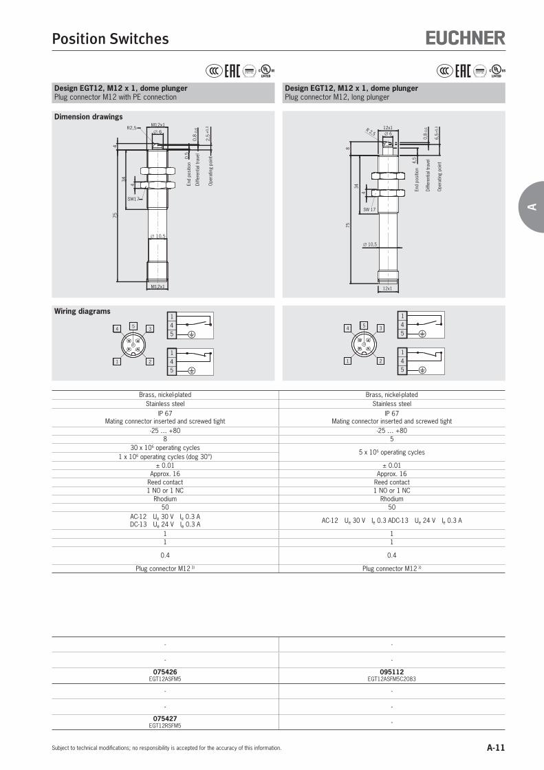
Design EGT12, M12 x 1, dome plungerPlug connector M12, long plunger
8
4,5
0,8
-0,6
6,5
±0,
3
75
34
4
12x1
∅ 10,5
12x1
R 2,5
SW 17
∅ 6
End
posi
tion
Diffe
rent
ial t
rave
l
Ope
ratin
g po
int
Design EGT12, M12 x 1, dome plungerPlug connector M12 with PE connection
541
�
541
�1 2
4 35
64
34
754
SW17
M12x1
2,5
±0,
3
0,8
-0,6
0,5
10,5
M12x1R2,5
End
posi
tion
Diffe
rent
ial t
rave
l
Ope
ratin
g po
int
Wiring diagrams
Dimension drawings
Brass, nickel-plated Brass, nickel-platedStainless steel Stainless steel
IP 67Mating connector inserted and screwed tight
IP 67Mating connector inserted and screwed tight
-25 … +80 -25 … +808 5
30 x 106 operating cycles5 x 106 operating cycles
1 x 10⁶ operating cycles (dog 30°)± 0.01 ± 0.01
Approx. 16 Approx. 16Reed contact Reed contact1 NO or 1 NC 1 NO or 1 NC
Rhodium Rhodium50 50
AC-12 Ue 30 V Ie 0.3 ADC-13 Ue 24 V Ie 0.3 A AC-12 Ue 30 V Ie 0.3 ADC-13 Ue 24 V Ie 0.3 A
1 11 1
0.4 0.4
Plug connector M12 3) Plug connector M12 3)
- -
- -
075426 EGT12ASFM5
095112 EGT12ASFM5C2083
- -
- -
075427 EGT12RSFM5 -
A-12
Position Switches
Subject to technical modifications; no responsibility is accepted for the accuracy of this information.
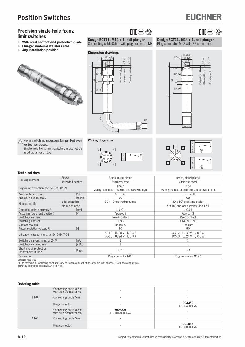
Design EGT11, M14 x 1, ball plungerPlug connector M12 with PE connection
541
�
541
�1 2
4 35
6
M14x1
15,8
43
34
754
SW10
R2
SW15
M12x1
2,5
±0,
3
0,8
-0,6
0,5
End
posi
tion
Diffe
rent
ial t
rave
l
Ope
ratin
g po
int
Design EGT11, M14 x 1, ball plungerConnecting cable 0.5 m with plug connector M8
End
posi
tion
Diffe
rent
ial t
rave
l
Ope
ratin
g po
int
1 3
2 4
42
Precision single hole fixing limit switches
With reed contact and protective diode Plunger material stainless steel Any installation position
0,5
0,8
-0,6
2,5
±0,
3
SW15
R2
SW10
461
343
4
15,8M14x1
6
50+
10
M8
Wiring diagrams
Dimension drawings
Never switch incandescent lamps. Not even for test purposes.
Single hole fixing limit switches must not be used as an end stop.
Technical data
Housing materialSleeve Brass, nickel-plated Brass, nickel-platedThreaded section Stainless steel Stainless steel
Degree of protection acc. to IEC 60529 IP 67Mating connector inserted and screwed tight
IP 67Mating connector inserted and screwed tight
Ambient temperature [°C] -5 … +65 -25 … +80Approach speed, max. [m/min] 60 60
Mechanical lifeaxial actuation 30 x 106 operating cycles 30 x 106 operating cyclesradial actuation - 5 x 10⁶ operating cycles (dog 15°)
Operating point accuracy 2) [mm] ± 0.01 ± 0.01Actuating force (end position) [N] Approx. 2 Approx. 3Switching element Reed contact Reed contactSwitching contact 1 NC 1 NO or 1 NCContact material Rhodium RhodiumRated insulation voltage Ui [V] 50 50
Utilization category acc. to IEC 60947-5-1 AC-12 Ue 30 V Ie 0.3 ADC-13 Ue 24 V Ie 0.3 A
AC-12 Ue 30 V Ie 0.3 ADC-13 Ue 24 V Ie 0.3 A
Switching current, min., at 24 V [mA] 1 1Switching voltage, min. [V DC] 1 1Short circuit protection(control circuit fuse) [A gG] 0.4 0.4
Connection Plug connector M8 3) Plug connector M12 3)
1) Cable hard wired.2) The reproducible operating point accuracy relates to axial actuation, after run-in of approx. 2,000 operating cycles.3) Mating connector see page A-44 to A-46.
Ordering table
1 NO
Connecting cable 0.5 mwith plug connector M8 - -
Connecting cable 5 m - -
Plug connector - 093352 EGT11A2NSFM5
1 NC
Connecting cable 0.5 mwith plug connector M8
084000 EGT11R2N50SAM4 -
Connecting cable 5 m - -
Plug connector - 091848 EGT11R2NSFM5

A-13
Position Switches
Subject to technical modifications; no responsibility is accepted for the accuracy of this information.
A
Design EGT12, M12 x 1, roller plungerPlug connector M12, double insulated
1 2
4 3
421
21
4
SW17
M12x1
2,5
±0,
3
0,8
-0,6
0,5
10,5
M12x1R2,5
4
SW10
3
36
77
End
posi
tion
Diffe
rent
ial t
rave
l
Ope
ratin
g po
int
Wiring diagrams
Dimension drawings
Brass, nickel-platedStainless steel
IP 67Mating connector inserted and screwed tight
-25 … +8020
30 x 106 operating cycles
± 0.01Approx. 16
Reed contact1 NO or 1 NC
Rhodium50 �
AC-12 Ue 30 V Ie 0.3 ADC-13 Ue 24 V Ie 0.3 A
11
0.4
Plug connector M12 3)
-
-
078483 EGT12ARSEM4C1888
-
-
079139 EGT12RRSEM4C1888

A-14
Position Switches
Subject to technical modifications; no responsibility is accepted for the accuracy of this information.
1 2
4 343
21
Precision single hole fixing limit switches
With reed contact Plunger material stainless steel Any installation position
Design EGT1/4, M14 x 1, ball plungerPlug connector M12
1 2
4 3
41
M14x1 15,8
43
34
4
SW10
R2
SW15
M12x1
2,5
±0,
3
0,8
-0,6
0,5
63
6
End
posi
tion
Diffe
rent
ial t
rave
l
Ope
ratin
g po
int
For mating connector with LED display
Design EGT1/4, M14 x 1, ball plungerConnecting cable, double insulated/plug con. M12
BUBN
BUBN
12,6
2,5
±0,
3
6M14x1
3
34
4
SW10
R2
0,8
-0,6
0,5
50SW15
4
15,8
5,4
End
posi
tion
Diffe
rent
ial t
rave
l
Ope
ratin
g po
int
Dimension drawings
Wiring diagrams
M12x1
63
Never switch incandescent lamps. Not even for test purposes.
Single hole fixing limit switches must not be used as an end stop.
Technical data
Housing materialSleeve Plastic Brass, nickel-plated Brass, nickel-platedThreaded section Stainless steel Stainless steel
Degree of protection acc. to IEC 60529 IP 68 IP 67 4) IP 67Mating connector inserted and screwed tight
Ambient temperature [°C] -25 1) … +80 -25 … +80 -25 … +80Approach speed, max. [m/min] 8 8Mechanical life (axial) 30 x 106 operating cycles 30 x 106 operating cyclesOperating point accuracy 2) [mm] ± 0.01 ± 0.01Actuating force (end position) [N] Approx. 16 / 3 on request Approx. 16 / 3 on requestSwitching element Reed contact Reed contactSwitching contact 1 NO or 1 NC 1 NOContact material Rhodium RhodiumRated insulation voltage Ui [V] 250 � 50 50
Utilization category acc. to IEC 60947-5-1AC-12 Ue 230 V Ie 0.03 A
Ue 24 V Ie 0.3 AUe 30 V Ie 0.3 AUe 24 V Ie 0.3 A
AC-12 Ue 30 V Ie 0.3 ADC-13 Ue 24 V Ie 0.3 ADC-13
Switching current, min., at 24 V [mA] 1 1Switching voltage, min. [V DC] 1 1Short circuit protection(control circuit fuse) [A gG] 0.4 0.4
ConnectionPUR cable
2 x 0.5 mm², encapsulated
Plug connector M12 3) Plug connector M12 3)
1) Cable hard wired.2) The reproducible operating point accuracy relates to axial actuation, after run-in of approx. 2,000 operating cycles.3) Mating connector see page A-44 to A-46.4) Mating connector inserted and screwed tight
Ordering table
1 NO
Connecting cable 2 m 001366 EGT1/4A2000 -
Connecting cable 5 m 001368 EGT1/4A5000 -
Plug connector 033976 EGT1/4ASEM4
075644 EGT1/4ASEM4C1802
1 NC
Connecting cable 2 m 001371 EGT1/4R2000 -
Connecting cable 5 m 001372 EGT1/4R5000 -
Plug connector 033982 EGT1/4RSEM4 -

A-15
Position Switches
Subject to technical modifications; no responsibility is accepted for the accuracy of this information.
A
Design EGT1/4, M14 x 1, ball plungerConnecting cable, max. pressure 300 kPa
Made of high-quality stainless steel
BUBN
∅ 12,6
50
SW15
SW10
0,8
2,5
0,5
34 4
4
3
M14x1
∅ 15,8
∅ 6
∅ 6,5
±0,
3
-0,6
Diffe
rent
ial t
rave
l
End
posi
tion
Ope
ratin
g po
int
Dimension drawings
Design EGT1/4, M14 x 1, ball plungerPlug connector M12
With scraper made of PU
1 2
4 343
21
7,5±
0,3
0,8 -
0,6
9
M14x1
∅ 15,8
4
M12x1
34
63
SW 15
5
∅ 6
ScraperMaterial PU91 Shore AColor gray
End
posi
tion
Diffe
rent
ial t
rave
l
Ope
ratin
g po
int
Design EGT1/4, M14 x 1, dome plungerPlug connector M12
With scraper made of PU
11,3
±0,
3
0,8
-0,6
12,5
M14x1
∅ 15,8
4
M12x1
47
76
SW 15
EGT.
.A...
4,
5EG
T..R
...
9,0
∅ 6
ScraperMaterial PU91 Shore AColor gray
Ope
ratin
g po
int
Diffe
rent
ial t
rave
l
End
posi
tion
(dim
ensi
on ty
pe
depe
nden
t)
Wiring diagrams
1 2
4 343
21
High-quality stainless steelBrass, nickel-plated Brass, nickel-plated
Stainless steel Stainless steel
IP 68 IP 67Mating connector inserted and screwed tight
IP 67Mating connector inserted and screwed tight
-25 … +80 -25 … +80 -25 … +808 Approx. 16 8
30 x 106 operating cycles 5 x 10⁶ operating cycles 30 x 106 operating cycles± 0.01 ± 0.01 ± 0.01
Approx. 16 Approx. 16 Approx. 16Reed contact Reed contact Reed contact
1 NO 1 NO or 1 NC 1 NO or 1 NCRhodium Rhodium Rhodium
50 50 50AC-12 Ue 30 V Ie 0.3 ADC-13 Ue 24 V Ie 0.3 A
AC-12 Ue 30 V Ie 0.3 ADC-13 Ue 24 V Ie 0.3 A
AC-12 Ue 30 V Ie 0.3 ADC-13 Ue 24 V Ie 0.3 A
1 1 11 1 1
0.4 0.4 0.4
Hydrofirm cable 2 x 0.5 mm², encapsulated Plug connector M12 3) Plug connector M12 3)
094982 EGT1/4A2000C2079 - 102476
EGT1/4A2000C2137
- - -
- 095278 EGT1/4ASEM4C2088
098071 EGT1/4ASEM4C2137
- - -
- - -
- 104316 EGT1/4RSEM4C2088
104372 EGT1/4RSEM4C2137

A-16
Position Switches
Subject to technical modifications; no responsibility is accepted for the accuracy of this information.
SW13
6
12
2,5
+0,
2
5,5M8x0,5
2±
0,3
0,12
±0,
06
0,5
40
10
R3
1000
Diffe
rent
ial t
rave
l
End
posi
tion
Ope
ratin
g po
int
Precision single hole fixing limit switches
With snap-action switching element Plunger material stainless steel Any installation position
Design EGM12, M12 x 1, flat plungerConnecting cable, double insulated
6
16
1,5
+0,
2
5,5M12x1
1±
0,3
0,12
±0,
06
0,5
1200
40
8
30
14
Diffe
rent
ial t
rave
l
End
posi
tion
Ope
ratin
g po
int
BKBUBN
… C1791
WH
GNBN
… C1820
Single hole fixing limit switches must not be used as an end stop.
Technical dataHousing material Stainless steel Stainless steel
Degree of protection acc. to IEC 60529 IP 65 IP 65
Ambient temperature [°C] -20 1) … +80 -20 1) … +80 -30 … +80Approach speed, max. [m/min] 8 8Mechanical life (axial) 1 x 10⁶ operating cycles 1 x 10⁶ operating cyclesOperating point accuracy 2) [mm] ± 0.01 ± 0.01Actuating force (end position) [N] Approx. 16 Approx. 16Switching element Snap-action switching contact Snap-action switching contactSwitching contact 1 changeover contact 1 changeover contactContact material Fine silver, gold-plated Silver alloy, gold-platedRated insulation voltage Ui [V] 250 � 250 �Rated impulse withstand voltage Uimp 2.5 2.5
Utilization category acc. to IEC 60947-5-1 AC-15 Ue 230 V Ie 0.5 ADC-13 Ue 24 V Ie 0.6 A
AC-15 Ue 230 V Ie 0.5 ADC-13 Ue 24 V Ie 0.6 A
Switching current, min., at 24 V [mA] 10 10Switching voltage, min. [V DC] 12 12Short circuit protection(control circuit fuse) [A gG] 2 2
Connection PUR cable 3 x 0.5 mm²
PUR cable 3 x 0.5 mm²
Silicone cable 3 x 0.5 mm²
1) Cable hard wired.2) The reproducible operating point accuracy relates to axial actuation, after run-in of approx. 2,000 operating cycles.3) Mating connector see page A-44 to A-46.
Ordering table
1 changeover contact
Connecting cable 1 m 119345 EGM8-1000C2396 - -
Connecting cable 1.2 m - 075556 EGM12-1200C1791
076464 EGM12-1200C1820
Connecting cable 2 m - - -
Connecting cable 2.5 m - - -
Connecting cable 4 m - 076154 EGM12-4000C1791 -
Connecting cable 5 m - - -
Plug connector - - -
Dimension drawings
Wiring diagrams
Design EGM8, M8 x 0.5, dome plungerConnecting cable, double insulated
BKBUBN

A-17
Position Switches
Subject to technical modifications; no responsibility is accepted for the accuracy of this information.
A
Design EGM12, M12 x 1, flat plungerPlug connector M8
1±
0,3
1,5
+0,
2
>0,
2
50
M8x1
0,12
M12x1 5,5
M12x1
84
164
10,8
SW17
4,8
15,8
±0,
06Di
ffere
ntia
l tra
vel
End
posi
tion
Ope
ratin
g po
int
41
31
4
Design EGM12, M12 x 1, flat plungerPlug connector M12
421
1 2
4 3
M12x1
1657
4
SW17 10,5
141,
5+
0,2
1±
0,3
0,12
±0,
06
0,5
Diffe
rent
ial t
rave
l
End
posi
tion
Ope
ratin
g po
int
Stainless steel Stainless steel Stainless steel
IP 65 IP 65Mating connector inserted and screwed tight
IP 65Mating connector inserted and screwed tight
-20 1) … +80 -30 … +80 -20 … +80 -30 … +85 -20 … +858 8 8
1 x 10⁶ operating cycles 1 x 10⁶ operating cycles 1 x 10⁶ operating cycles± 0.01 ± 0.01 ± 0.01
Approx. 16 Approx. 16 Approx. 16Snap-action switching contact Snap-action switching contact Snap-action switching contact
1 changeover contact 1 changeover contact 1 NOFine silver, gold-plated Silver alloy, gold-plated Silver alloy, gold-plated
250 � 50 502.5 1.5 1.5
AC-15 Ue 230 V Ie 0.5 ADC-13 Ue 24 V Ie 0.6 A
AC-15 Ue 50 V Ie 0.5 ADC-13 Ue 24 V Ie 0.6 A
AC-15 Ue 24 V Ie 0.5 ADC-13 Ue 24 V Ie 0.6 A
10 10 1012 12 12
2 2 2
PUR cable 3 x 0.5 mm²
Silicone cable 3 x 0.5 mm² Plug connector M12 3) Plug connector M8 3)
- - - - -
- 128196 EGM12-1200C2463 - - -
- - - - -
126384 EGM12-2500C2452 - - - -
- - - - -
- - - - -
- - 082205 EGM12SEM4
093733 EGM12SEM4C1820
077228 EGM12SAM3C1868
Design EGM12, M12 x 1, dome plungerFor sealing with O-rings
BKBUBN
… C2452
WH
GNBN
… C2463
6
16
2,5
+0,
2
5,5M12x1
2±
0,3
0,12
±0,
06
0,5
Sili
con
1200
PUR
40
8
14
R3
2500
Diffe
rent
ial t
rave
l
End
posi
tion
Ope
ratin
g po
int
Dimension drawings
Wiring diagrams

A-18
Position Switches
Subject to technical modifications; no responsibility is accepted for the accuracy of this information.
Technical dataHousing material Brass, nickel-plated Brass, nickel-plated
Degree of protection acc. to IEC 60529 IP 67 IP 67Mating connector inserted and screwed tight
Ambient temperature [°C] -25 1) … +80 -25 … +80Approach speed, max. [m/min] 8 8Mechanical life (axial) 1 x 10⁶ operating cycles 1 x 10⁶ operating cyclesOperating point accuracy 2) [mm] ± 0.01 ± 0.01Actuating force (end position) [N] Approx. 20 Approx. 20Switching element Snap-action switching contact Snap-action switching contactSwitching contact 1 changeover contact 1 changeover contactContact material Silver alloy, gold-plated Silver alloy, gold-platedRated insulation voltage Ui [V] 250 50Rated impulse withstand voltage Uimp 2.5 2.5
Utilization category acc. to IEC 60947-5-1 AC-15 Ue 230 V Ie 0.5ADC-13 Ue 24 V Ie 0.6 A
AC-15 Ue 50 V Ie 0.5 ADC-13 Ue 24 V Ie 0.6 A
Switching current, min., at 24 V [mA] 10 10Switching voltage, min. [V DC] 12 12Short circuit protection(control circuit fuse) [A gG] 2 2
Connection PUR cable 4 x 0.5 mm² Plug connector M12 3)
1) Cable hard wired.2) The reproducible operating point accuracy relates to axial actuation, after run-in of approx. 2,000 operating cycles.3) Mating connector see page A-44 to A-46.
Design EGT1, M12 x 1, ball plungerConnecting cable with PE connection
BKBUBN
GNYE �
12,6
SW10
3,5
0,15
0,5
427
3
M12x1
6
SW17
3
18
65
6,0
±0,
3
Diffe
rent
ial t
rave
l
End
posi
tion
Ope
ratin
g po
int
Design EGT1, M12 x 1, ball plungerPlug connector M12
421
1 2
4 3
3,5
0,15
0,5
±0,
3
M12x1
6
M12x1
SW17
427
33
18
12,6
74
Diffe
rent
ial t
rave
l
End
posi
tion
Ope
ratin
g po
int
Precision single hole fixing limit switches
With snap-action switching element Plunger material stainless steel Any installation position
Single hole fixing limit switches must not be used as an end stop.
Dimension drawings
Wiring diagrams
Ordering table
1 changeover contact
Connecting cable 2 m 092695 EGT1M12-2000 -
Connecting cable 5 m 093364 EGT1M12-5000 -
Plug connector - 093365 EGT1M12SEM4
A-19
Position Switches
Subject to technical modifications; no responsibility is accepted for the accuracy of this information.
A

A-20
Position Switches
Subject to technical modifications; no responsibility is accepted for the accuracy of this information.
Precision single hole fixing limit switches
With snap-action switching element Plunger material stainless steel Any installation position
Dimension drawings
Wiring diagrams
Design EGT1, M14 x 1, ball plungerConnecting cable with PE connection
Design EGT1, M14 x 1, ball plungerPlug connector M12
BKBUBN
GNYE � 431
1 2
4 3
4
3,5
0,150,5
15,8
M14x1
6
74
27
34
SW 15
M12x1
±0,
3
Diffe
rent
ial t
rave
l
End
posi
tion
Ope
ratin
g po
int
12
3,5
0,15
0,5
4
4
65
27
3
M14x1
15,8
6
SW 15
SW 10
±0,
3
6,0
Diffe
rent
ial t
rave
l
End
posi
tion
Ope
ratin
g po
int
Single hole fixing limit switches must not be used as an end stop.
Technical dataHousing material Brass, nickel-plated Brass, nickel-plated
Degree of protection acc. to IEC 60529 IP 67 IP 67Mating connector inserted and screwed tight
Ambient temperature [°C] -25 1) … +80 -25 … +80Approach speed, max. [m/min] 8 8Mechanical life (axial) 1 x 10⁶ operating cycles 1 x 10⁶ operating cyclesOperating point accuracy 2) [mm] ± 0.01 ± 0.01Actuating force (end position) [N] Approx. 20 Approx. 20Switching element Snap-action switching contact Snap-action switching contactSwitching contact 1 changeover contact 1 changeover contactContact material Silver alloy, gold-plated Silver alloy, gold-platedRated insulation voltage Ui [V] 250 50Rated impulse withstand voltage Uimp 2.5 2.5
Utilization category acc. to IEC 60947-5-1 AC-15 Ue 230 V Ie 0.5 ADC-13 Ue 24 V Ie 0.6 A
AC-15 Ue 50 V Ie 0.5 ADC-13 Ue 24 V Ie 0.6 A
Switching current, min., at 24 V [mA] 10 10Switching voltage, min. [V DC] 12 12Short circuit protection(control circuit fuse) [A gG] 2 2
Connection PUR cable 4 x 0.5 mm² Plug connector M12 3)
1) Cable hard wired.2) The reproducible operating point accuracy relates to axial actuation, after run-in of approx. 2,000 operating cycles.3) Mating connector see page A-44 to A-46.
Ordering table
1 changeover contact
Connecting cable 2 m 001732 EGT1-2000 -
Connecting cable 5 m 001733 EGT1-5000 -
Plug connector - 019727 EGT1SEM4

A-21
Position Switches
Subject to technical modifications; no responsibility is accepted for the accuracy of this information.
A
Design EGT1, M14 x 1, ball plungerPlug connector M12
For plug connector with LED display
Suitable for aggressive coolant; diaphragm made of Viton
Design EGT1, M14 x 1, ball plungerPlug connector M12
431
1 2
4 3
WHBN
BK 4
21
3BU
+
-
GN YE YE 421
31 2
4 3
4
3,5
0,150,5
15,8
M14x1
6
74
27
34
SW 15
M12x1
±0,
3
Diffe
rent
ial t
rave
l
End
posi
tion
Ope
ratin
g po
int
4
3,5
0,150,5
15,8
M14x1
6
74
27
34
SW 15
M12x1
±0,
3
Diffe
rent
ial t
rave
l
End
posi
tion
Ope
ratin
g po
int
Dimension drawings
Wiring diagrams
Brass, nickel-plated Brass, nickel-plated Brass, nickel-platedIP 67
Mating connector inserted and screwed tightIP 67
Mating connector inserted and screwed tightIP 67
Mating connector inserted and screwed tight-25 … +80 -5 … +80 -5 … +80
8 8 81 x 106 operating cycles 1 x 10⁶ operating cycles 1 x 10⁶ operating cycles
± 0.01 ± 0.01 ± 0.01Approx. 20 Approx. 20 Approx. 20
Snap-action switching contact Snap-action switching contact Snap-action switching contact1 changeover contact 1 changeover contact 1 changeover contactSilver alloy, gold-plated Silver alloy, gold-plated Silver alloy, gold-plated
50 50 502.5 2.5 2.5
DC-13 Ue 24 V Ie 0.6 A AC-15 Ue 50 V Ie 0.5 ADC-13 Ue 24 V Ie 0.6 A AC-15 Ue 50 V Ie 0.5 ADC-13 Ue 24 V Ie 0.6 A
10 10 1012 12 12
2 2 2
Plug connector M12 3) Plug connector M12 3) Plug connector M12 3)
- - -
- - -
054250 EGT1SEM4C1613
102479 EGT1SEM4C2221
077347 EGT1SEM4C1832
Design EGT1, M14 x 1, ball plungerPlug connector M12
For plug connector with LED display
WHBN
BK 4
21
3BU
+
-
GN YE YE 421
31 2
4 34
3,5
0,150,5
15,8
M14x1
6
74
27
34
SW 15
M12x1
±0,
3
Diffe
rent
ial t
rave
l
End
posi
tion
Ope
ratin
g po
int

A-22
Position Switches
Subject to technical modifications; no responsibility is accepted for the accuracy of this information.
Precision single hole fixing limit switches
Dimension drawings
With snap-action switching element Plunger material stainless steel Any installation position
Wiring diagrams
Design EGT2, M18 x 1.5, ball plungerConnecting cable with PE connection
Design EGT2, M18 x 1.5, ball plungerPlug connector M12
BUBN
BKBK
GNYE �
21
341 3
2 4
SW 22
M12x1
16
32
0,5
0,5
4
24M18x1,5
9
593
44
Diffe
rent
ial t
rave
l
End
posi
tion
Ope
ratin
g po
int
5
32
4
0,5
0,5
4
4
24M18x1,5
9
85
16
SW 22
SW 14
7,2
Diffe
rent
ial t
rave
l
End
posi
tion
Ope
ratin
g po
int
Single hole fixing limit switches must not be used as an end stop.
Technical dataHousing material Brass, nickel-plated Brass, chromium-plated
Degree of protection acc. to IEC 60529 IP 67 IP 67Mating connector inserted and screwed tight
Ambient temperature [°C] -5 … +60 -5 … +60Approach speed, max. [m/min] 10 10Mechanical life 1 x 10⁶ operating cycles 1 x 10⁶ operating cyclesOperating point accuracy 1) [mm] ± 0.01 ± 0.01Actuating force (end position) [N] Approx. 24 Approx. 24Switching element Snap-action switching contact Snap-action switching contactSwitching contact 1 NC and 1 NO 1 NC and 1 NOContact material Fine silver, gold-plated Fine silver, gold-platedRated insulation voltage Ui [V] 250 50Rated impulse withstand voltage Uimp 2.5 2.5
Utilization category acc. to IEC 60947-5-1 AC-15 Ue 230 V Ie 2 ADC-13 Ue 24 V Ie 1 A
AC-15 Ue 30 V Ie 2 ADC-13 Ue 24 V Ie 1 A
Switching current, min., at 24 V [mA] 10 10Switching voltage, min. [V DC] 12 12Short circuit protection(control circuit fuse) [A gG] 2 2
Connection PUR cable 5 x 0.75 mm² Plug connector M12 2)
1) The reproducible operating point accuracy relates to axial actuation, after run-in of approx. 2,000 operating cycles.2) Mating connector see page A-44 to A-46.
Ordering table
1 NC + 1 NO
Connecting cable 2 m 001864 EGT2-2000 -
Connecting cable 5 m 001865 EGT2-5000 -
Plug connector - 052504 EGT2SEM4
A-23
Position Switches
Subject to technical modifications; no responsibility is accepted for the accuracy of this information.
A
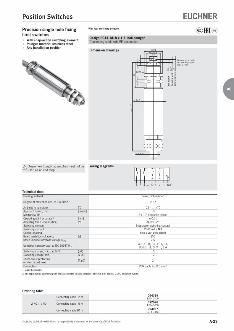
Design EGT4, M18 x 1.5, ball plungerConnecting cable with PE connection
With four switching contacts
65 7 8 GNYE21 3 4
�
Precision single hole fixing limit switches
With snap-action switching element Plunger material stainless steel Any installation position
Wiring diagrams
9M18x1,5
24
54
432
24,5
max
. 115
0,5
3,5
±0,
7
1,2
SW22
8,6±0,4
Dimension drawings
Diffe
rent
ial t
rave
l
End
posi
tion
Ope
ratin
g po
int
Distance between the two operating points max. 0.7 mm
Single hole fixing limit switches must not be used as an end stop.
Technical dataHousing material Brass, nickel-plated
Degree of protection acc. to IEC 60529 IP 67
Ambient temperature [°C] -25 1) … +70Approach speed, max. [m/min] 10Mechanical life 5 x 10⁵ operating cyclesOperating point accuracy 2) [mm] ± 0.01Actuating force (end position) [N] Approx. 25Switching element Snap-action switching contactSwitching contact 2 NC and 2 NOContact material Fine silver, gold-platedRated insulation voltage Ui [V] 250Rated impulse withstand voltage Uimp 2.5
Utilization category acc. to IEC 60947-5-1 AC-15 Ue 230 V Ie 2 ADC-13 Ue 24 V Ie 1 A
Switching current, min., at 24 V [mA] 10Switching voltage, min. [V DC] 12Short circuit protection(control circuit fuse) [A gG] 2
Connection PUR cable 9 x 0.5 mm²1) Cable hard wired.
2) The reproducible operating point accuracy relates to axial actuation, after run-in of approx. 2,000 operating cycles.
Ordering table
2 NC + 1 NO
Connecting cable 2 m 094339 EGT4-2000
Connecting cable 5 m 092026 EGT4-5000
Connecting cable 10 m 093967 EGT4-10000

A-24
Position Switches
Subject to technical modifications; no responsibility is accepted for the accuracy of this information.
Design EGZ12, M12 x 1, dome plungerConnecting cable with PE connection
Switching element, with three switching contactsPrecision single hole fixing limit switches
With slow-action switching element Plunger and housing made of high-quality stainless steel
Any installation position Threaded section M12 x 1
Wiring diagrams
Dimension drawings
M12x1
36
123
mm
3
Ø 6 R 2,5
5
13-1
4
21-2
2
31-3
2
ES12
SW 17
0
1
4
2
3
SW 10
5
Ø 28
Ø 6,5
21-2
2
31-3
2
ES03
4,23,4
11-1
2
Actuating direction
Tota
l stro
ke
Cabl
e le
ngth
“L”
Do not press plunger all the way to the stop
Travel diagram
13
2131
14
2232 5 - 6
3 - 4
1 - 2
GNYE
ES12 Single hole fixing limit switches must not be used as an end stop.
Technical dataHousing material Stainless steelPlunger material Stainless steel 60 HRC hardened and polish-ground
Degree of protection acc. to IEC 60529 IP 67
Ambient temperature [°C] -20 1) … +80Approach speed, max. [m/min] 8Mechanical life 3 x 10⁶ operating cyclesActuating force at 20 °C [N] < 16Switching element Slow-action switching contactSwitching contact See travel diagramContact material Silver alloy, gold flashedRated insulation voltage Ui [V] 250Rated impulse withstand voltage Uimp 2.5
Utilization category acc. to IEC 60947-5-1 AC-15 Ue 230 V Ie 4 ADC-13 Ue 24 V Ie 4 A
Switching current, min., at 24 V [mA] 1Switching voltage, min. [V DC] 12Short circuit protection(control circuit fuse) [A gG] 4
Connection PUR cable 7 x 0.5 mm²1) Cable hard wired.
Ordering tableConnecting cable ES12
Connecting cable 5 m 094823 EGZ12-12-5000
A-25
Position Switches
Subject to technical modifications; no responsibility is accepted for the accuracy of this information.
A
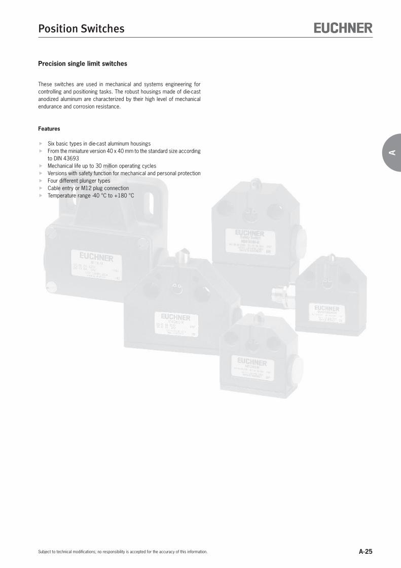
Precision single limit switches
These switches are used in mechanical and systems engineering for controlling and positioning tasks. The robust housings made of die-cast anodized aluminum are characterized by their high level of mechanical endurance and corrosion resistance.
Features
Six basic types in die-cast aluminum housings From the miniature version 40 x 40 mm to the standard size according
to DIN 43693 Mechanical life up to 30 million operating cycles Versions with safety function for mechanical and personal protection Four different plunger types Cable entry or M12 plug connection Temperature range -40 °C to +180 °C

A-26
Position Switches
Subject to technical modifications; no responsibility is accepted for the accuracy of this information.
Precision single limit switches
Dimension drawings
Plunger material stainless steel
Wiring diagrams
Design N01Cable entry M12 x 1.5
Design N01Cable entry M12 x 1.5
For temperatures up to 180 °C
421
�
ES550/ES562
421
�
ES572
40
20
6
25
4,3
89,
511
13,5
27
12,5
402
M12x1,5
4,2
30°
Free
pos
ition
Ope
ratin
g po
int
Plunger depending on designFree position dimension same for all plungersDog
Diffe
rent
ial t
rave
l 0.
1
40
20
6
25
4,3
8
9,5
11
13,5
27
12,5
402
M12x1,5
4,2
30°
Free
pos
ition
Ope
ratin
g po
int
Plunger depending on designFree position dimension same for all plungers
Dog
Diffe
rent
ial t
rave
l 0.
1
Technical dataHousing material Die-cast aluminum, anodized Die-cast aluminum, anodized
Degree of protection acc. to IEC 60529 IP 67 IP 67
Ambient temperature [°C] -5 … +80 -5 … +180Plunger type Chisel Roller Ball Chisel Roller BallOperating point accuracy 1) [mm] ± 0.02 ± 0.05 ± 0.03 ± 0.02 ± 0.05 ± 0.03Approach speed, max. 2) [m/min] 20 50 8 20 50 8Approach speed, min. [m/min] 0.01 0.01Actuating force, max. [N] 15 15Switching element ES550 ES562 ES572Switching contact 1 changeover contact 1 changeover contactSwitching principle Snap-action switching contact Snap-action switching contact
Mechanical life 1 x 10⁷ operating cycles 5 x 10⁵ operating cycles at -5 … +125 °C,200 h at +180 °C
Rated impulse withstand voltage Uimp [kV] 2.5 2.5
Rated insulation voltage Ui [V] 250 250
Utilization category acc. to IEC 60947-5-1 AC-15 Ue 230 V Ie 2 ADC-13 Ue 24 V Ie 2 A
DC-13 Ue 30 V Ie 100 mA
AC-15 Ue 230 V Ie 4 ADC-13 Ue 24 V Ie 1 A
Contact material Silver, gold-plated Gold alloy Fine silverSwitching current, min., at switching voltage
[mA] 10 5 10[V DC] 24 5 12
Short circuit protection(control circuit fuse) [A gG] 6 0.125 5
Connection Soldered connection, 1.0 mm² max. Soldered connection, 1.0 mm² max.1) The reproducible operating point accuracy relates to axial actuation, after run-in of approx. 2,000 operating cycles.2) The approach speed applies to a trip dog approach angle of 30°, 100 mm long, hardened and ground.3) Mating connector see page A-44 to A-46.
Ordering tablePlunger type ES550 ES562 ES572
Chisel plunger120° 084902 4)
N01D550-M087151
N01D562-M087162
N01D572-M
Roller plungerR
R = 2.5 mm 084903 4) N01R550-M
085243 N01R562-M
087163 N01R572-M
Ball plunger 084904 4) N01K550-M
087152 N01K562-M
087164 N01K572-M
4) CCC approval only for switching element ES550
4)

A-27
Position Switches
Subject to technical modifications; no responsibility is accepted for the accuracy of this information.
A
Dimension drawings
Wiring diagrams
Design N01Cable gland M12 x 1.5
Design N01Connecting cable, length 5 m
Design N01M12 plug adjustable, 4-pin + PE
421
�
ES550
BKBUBN
GNYE �
ES550
421
5 �
ES550
1 2
4 35
Cable diameter4 - 6.5 mm
40
20
6
25
4,3
8
9,511 13,5
27
12,5
402
M12x1,5
4,2
30° max.
Free
pos
ition
Ope
ratin
g po
int
Plunger depending on designFree position dimension same for all plungers
Dog
Diffe
rent
ial t
rave
l 0.
1
4020
6
25
4,3
8
9,5
11 13,5
27
12,5
402
4,2
20
30° max.
Free
pos
ition
Ope
ratin
g po
int
Plunger depending on designFree position dimension same for all plungers
Dog
Diffe
rent
ial t
rave
l 0.
1
4020
6
25
4,3
8
9,5
11 13,5
27
12,5
40
4,2
24
30° max.
Free
pos
ition
Ope
ratin
g po
int
Plunger depending on designFree position dimension same for all plungersDog
Diffe
rent
ial t
rave
l 0.
1
Die-cast aluminum, anodized Die-cast aluminum, anodized Die-cast aluminum, anodized
IP 67 IP 67 IP 67Mating connector inserted and screwed tight
-5 … +80 -5 … +80 -5 … +80Chisel Roller Ball Chisel Roller Ball Chisel Roller Ball± 0.02 ± 0.05 ± 0.03 ± 0.02 ± 0.05 ± 0.03 ± 0.02 ± 0.05 ± 0.03
20 50 8 20 50 8 20 50 80.01 0.01 0.0115 15 15
ES550 ES550 ES550 ES5621 changeover contact 1 changeover contact 1 changeover contact
Snap-action switching contact Snap-action switching contact Snap-action switching contact
1 x 10⁷ operating cycles 1 x 10⁷ operating cycles 1 x 10⁷ operating cycles
2.5 2.5 1.5
250 250 50 50AC-15 Ue 230 V Ie 2 ADC-13 Ue 24 V Ie 2 A
AC-15 Ue 230 V Ie 2 ADC-13 e 24 V Ie 2 A
AC-15 Ue 30 V Ie 2 ADC-13 Ue 24 V Ie 3 A
DC-13 Ue 30 V Ie 100 mA
Silver, gold-plated Silver, gold-plated Silver, gold-plated Gold alloy10 10 10 524 24 24 5
6 6 4 0.125
Soldered connection, 1.0 mm² max. PUR cable 4 x 0.5 mm² Plug connector M12 3)
ES550 ES550 ES550 ES562
085708 4) N01D550-MC2018
088978 N01D550X5000-M
088623 N01D550SVM5-M -
094856 4) N01R550-MC2018
088982 N01R550X5000-M
088622 N01R550SVM5-M
093426 N01R562SVM5-M
089619 4) N01K550-MC2018
088986 N01K550X5000-M
088624 N01K550SVM5-M -
4)
A-28
Position Switches
Subject to technical modifications; no responsibility is accepted for the accuracy of this information.
4020
6
25
4,3
8
9,5
11 13,5
27
12,5
40
4,2
22
30° max.
Free
pos
ition
Ope
ratin
g po
int
Plunger depending on designFree position dimension same for all plungersDog
Diffe
rent
ial t
rave
l 0.
1
421
5 �
ES593
1 2
4 35
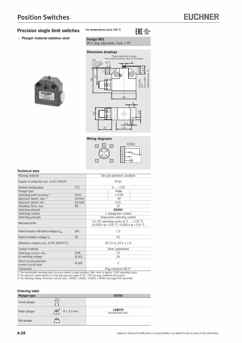
Precision single limit switches
Dimension drawings
Plunger material stainless steel
Wiring diagrams
Design N01M12 plug adjustable, 4-pin + PE
For temperatures up to 125 °C
Technical dataHousing material Die-cast aluminum, anodized
Degree of protection acc. to IEC 60529 IP 65
Ambient temperature [°C] -5 … +125Plunger type RollerOperating point accuracy 1) [mm] ± 0.05Approach speed, max. 2) [m/min] 50Approach speed, min. [m/min] 0.01Actuating force, max. [N] 15Switching element ES593Switching contact 1 changeover contactSwitching principle Snap-action switching contact
Mechanical life 5 x 10⁵ operating cycles at -5 … +125 °C,30,000 h at +100 °C / 8,000 h at +125 °C
Rated impulse withstand voltage Uimp [kV] 1.5
Rated insulation voltage Ui [V] 50
Utilization category acc. to IEC 60947-5-1 DC-13 Ue 24 V Ie 1 A
Contact material Silver, gold-platedSwitching current, min., at switching voltage
[mA] 10[V DC] 24
Short circuit protection(control circuit fuse) [A gG] 2
Connection Plug connector M12 3)
1) The reproducible operating point accuracy relates to axial actuation, after run-in of approx. 2,000 operating cycles.2) The approach speed applies to a trip dog approach angle of 30°, 100 mm long, hardened and ground.3) The following mating connectors can be used: 136960, 136961, 136962, 136963 (see page A-45 and A-46).
Ordering tablePlunger type ES550
Chisel plunger120°
-
Roller plungerR
R = 2.5 mm 128070 N01R593-MC2445
Ball plunger -

A-29
Position Switches
Subject to technical modifications; no responsibility is accepted for the accuracy of this information.
A

A-30
Position Switches
Subject to technical modifications; no responsibility is accepted for the accuracy of this information.
Dimension drawings
Wiring diagrams
Precision single limit switches Plunger material stainless steel Design N01
M12 plug, 4-pinDesign N01M12 plug, 4-pin + PE
WHBN
BK 4
21
3BU
+
-
GN YE YE
1 2
4 3
421
3
ES550
For operating voltage 230 V
1 2
4 35
421
5 �
ES550
To achieve the positively driven travel, the dimension 11-0,5 must be maintained by the trip dog. Actuating elements such as cam approach guides must be positively mounted in accordance with EN ISO 14119, i.e. riveted, welded or otherwise secured against becoming loose.
4020
6
25
4,3
89,
511 13
,5
27
12,5
40
4,2
1530° m
ax.
Free
pos
ition
Ope
ratin
g po
int
Plunger depending on designFree position dimension same for all plungers
Dog
Diffe
rent
ial t
rave
l 0.
1
4020
6
25
4,3
8
9,5
11 13,5
27
12,5
40
4,2
15
30° max.
Free
pos
ition
Ope
ratin
g po
int
Plunger depending on designFree position dimension same for all plungers
Dog
Diffe
rent
ial t
rave
l 0.
1
Technical dataHousing material Die-cast aluminum, anodized Die-cast aluminum, anodized
Degree of protection acc. to IEC 60529 IP 67Mating connector inserted and screwed tight
IP 67 Mating connector inserted and screwed tight
Ambient temperature [°C] -5 … +80 -5 … +80Plunger type Chisel Roller Ball Chisel Roller BallOperating point accuracy 1) [mm] ± 0.02 ± 0.05 ± 0.03 ± 0.02 ± 0.05 ± 0.03Approach speed, max. 2) [m/min] 20 50 8 20 50 8Approach speed, min. [m/min] 0.01 0.01Actuating force, max. [N] 15 15Switching element ES550 ES550Switching contact 1 changeover contact 1 changeover contactSwitching principle Snap-action switching contact Snap-action switching contactMechanical life 1 x 10⁷ operating cycles 1 x 10⁷ operating cycles
Rated impulse withstand voltage Uimp [kV] 2.0 1.5
Rated insulation voltage Ui [V] 50 250
Utilization category acc. to IEC 60947-5-1 DC-13 Ue 24 V Ie 2 A AC-15 Ue 230 V Ie 2 ADC-13 Ue 24 V Ie 2 A
Contact material Silver, gold-plated Silver, gold-platedSwitching current, min., at switching voltage
[mA] 10 10[V DC] 24 24
Short circuit protection(control circuit fuse) [A gG] 4 4
Connection Plug connector M12 3) Plug connector M12, B-coded 3)
1) The reproducible operating point accuracy relates to axial actuation, after run-in of approx. 2,000 operating cycles.2) The approach speed applies to a trip dog approach angle of 30°, 100 mm long, hardened and ground.3) Mating connector see page A-44 to A-46.4) 30 V AC Class 2 / 24 V DC Class 2
Ordering tablePlunger type ES550 ES550
Chisel plunger120° 091003
N01D550-MC1526 -
Roller plungerR
R = 2.5 mm 091001 N01R550-MC1526
091257 N01R550SEM5-M
Ball plunger 091002 N01K550-MC1526
091258 N01K550SEM5-M
For plug connector with LED display
4)

A-31
Position Switches
Subject to technical modifications; no responsibility is accepted for the accuracy of this information.
A
Dimension drawings
Wiring diagrams
Design NB01Cable entry M12 x 1.5
With safety function
Design NB01Cable entry M12 x 1.5
421
�
ES556
21
�
ES588
58
20
6
25
4,3
8
9,5
13,5
27
12,5
402
M12x1,5
4,2
30°
11-0
,5
±0,
3
Free
pos
ition
Ope
ratin
g po
int
Plunger depending on designFree position dimension same for all plungersDog
44
20
6
25
4,3
8
9,5
11 13,5
27
12,5
402
M12x1,5
4,2
30° max.
Free
pos
ition
Ope
ratin
g po
int
Plunger depending on designFree position dimension same for all plungersDog
Diffe
rent
ial t
rave
l 0.
2
Die-cast aluminum, anodized Die-cast aluminum, anodized Die-cast aluminum, anodized
IP 67 IP 67 IP 67
-25 … +60 -5 … +80 -5 … +80Chisel Roller Chisel Roller Ball Roller± 0.02 ± 0.05 ± 0.02 ± 0.05 ± 0.03 ± 0.05
20 50 20 50 8 500.01 0.01 0.0115 15 15
ES588 ES556 ES6201 NC 1 changeover contact 1 changeover contact
Slow-action switching contact Snap-action switching contact Snap-action switching contact1 x 107 operating cycles 1 x 10⁷ operating cycles 1 x 10⁷ operating cycles
2.5 2.5 2.5
250 250 250AC-15 Ue 230 V Ie 4 A DC-13 Ue 24 V Ie 3 A
AC-15 Ue 230 V Ie 2 ADC-13 Ue 24 V Ie 2 A
AC-15 Ue 230 V Ie 2 ADC-13 Ue 24 V Ie 2 A
Fine silver Silver, gold-plated Silver, gold-plated1 10 105 24 24
10 6 6
Screw terminal, 1.0 mm² max. 1.3 mm hexagon socket screw terminal/screw termi-nal, 1.0 mm² max. Screw terminal, 1.0 mm² max.
ES588 ES556 ES620
088584 NB01D588-M
085245 NB01D556-M -
088583 NB01R588-M
085246 NB01R556-M
102883 NB01R620-MC2276
- 085247 NB01K556-M -
Design NB01Cable gland M12 x 1.5
421
�
ES620
48,5
20
6
25
4,3
8
9,5
11 13,5
27
13
406
M12x1,5
4,2
30° max.
Free
pos
ition
Ope
ratin
g po
int
Plunger depending on designDog
Diffe
rent
ial t
rave
l 0.
2
Larger connection space, robust screw terminal

A-32
Position Switches
Subject to technical modifications; no responsibility is accepted for the accuracy of this information.
Precision single limit switches Plunger material stainless steel Design SN01
M12 plug adjustable, 4-pin + PE
1 2
4 35
21
345
1
3
2
4
�
ES558
6
9,5
11 13,5
27
12,5
5022
45
8
4,3
25
4,2
30° max.
20
Free
pos
ition
Ope
ratin
g po
int
Dog
Diffe
rent
ial t
rave
l 0.
5
Plunger depending on designFree position dimension same for all plungers
To achieve the positively driven travel, the dimension 12-0,5 must be maintained by the trip dog. Actuating elements such as cam approach guides must be positively mounted in accordance with EN ISO 14119, i.e. riveted, welded or otherwise secured against becoming loose.
Technical dataHousing material Die-cast aluminum, anodized Die-cast aluminum, anodized
Degree of protection acc. to IEC 60529 IP 67 IP 67Mating connector inserted and screwed tight
Ambient temperature [°C] -5 … +80 -5 … +80Plunger type Chisel Roller Ball Chisel Roller BallOperating point accuracy 1) [mm] ± 0.02 ± 0.05 ± 0.03 ± 0.02 ± 0.05 ± 0.03Approach speed, max. 2) [m/min] 20 50 8 20 50 8Approach speed, min. [m/min] 0.01 0.01Actuating force, max. [N] 15 15Switching element ES553 ES558 ES558Switching contact 1 changeover contact 1 NO + 1 NC 1 NO + 1 NCSwitching principle Snap-action switching contact Snap-action switching contactMechanical life 1 x 10⁷ operating cycles 1 x 10⁷ operating cycles
Rated impulse withstand voltage Uimp [kV] 2.5 1.5
Rated insulation voltage Ui [V] 250 30
Utilization category acc. to IEC 60947-5-1 AC-15 Ue 230 V Ie 2 ADC-13 Ue 24 V Ie 2 A
AC-15 Ue 230 V Ie 4 ADC-13 Ue 24 V Ie 3 A
AC-15 Ue 36 V Ie 4 ADC-13 Ue 24 V Ie 3 A
Contact material Silver, gold-plated Silver SilverSwitching current, min., at switching voltage
[mA] 10 10 10[V DC] 24 5 5
Short circuit protection(control circuit fuse) [A gG] 6 4 4
Connection Screw terminal, 1.0 mm² max.
Soldered connection, 1.0 mm² max. Plug connector M12 3)
1) The reproducible operating point accuracy relates to axial actuation, after run-in of approx. 2,000 operating cycles.2) The approach speed applies to a trip dog approach angle of 30°, 100 mm long, hardened and ground.3) Mating connector see page A-44 to A-46.
Ordering tablePlunger type ES553 ES558 ES558
Chisel plunger120° 085252 4)
SN01D553-M085260
SN01D558-M088625
SN01D558SVM5-M
Roller plungerR
R = 2.5 mm 085253 4) SN01R553-M
085261 SN01R558-M
088626 SN01R558SVM5-M
Ball plunger 085254 4) SN01K553-M
085262 SN01K558-M
088627 SN01K558SVM5-M
4) CCC approval only for switching element ES553
Design SN01Cable entry M16 x 1.5
421
�
ES553
21
34
�
ES558
6
9,5
11 13,5
27
12,5
M16x1,5
50
2245
8
4,3
25
4,2
30° max.
Free
pos
ition
Ope
ratin
g po
int
Plunger depending on designFree position dimension same for all plungersDog
Diffe
rent
ial t
rave
l 0.2
(ES5
53)
0.
5 (E
S558
)
Dimension drawings
Wiring diagrams
4)

A-33
Position Switches
Subject to technical modifications; no responsibility is accepted for the accuracy of this information.
A
Design SN01Connecting cable, length 2 m
BU/2BN/1
BK/3BK/4GNYE
1
3
2
4
�
ES558
R2,5 6
9,5
11 13,5
27
12,5
5022
45
8
4,3
25
4,2
30° max.
20
Free
pos
ition
Ope
ratin
g po
int
Dog
Diffe
rent
ial t
rave
l 0.
5
Plunger depending on design
Die-cast aluminum, anodized
IP 67
-5 … +80Roller
± 0.0550
0.0115
ES5581 NO + 1 NC
Snap-action switching contact1 x 107 operating cycles
2.5
250AC-15 Ue 230 V Ie 4 ADC-13 Ue 24 V Ie 3 A
Silver105
4
PUR cable 5 x 0.5 mm²
ES558
-
090515 SN01R558X2000-M
-
Dimension drawings
Wiring diagrams

A-34
Position Switches
Subject to technical modifications; no responsibility is accepted for the accuracy of this information.
Dimension drawings
Wiring diagrams
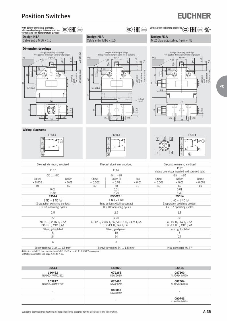
Precision single limit switches Plunger material stainless steel Housing according to DIN 43693 Low temperature down to -40 °C
Design N1ACable entry M16 x 1.5
With safety switching element
2839
60 (E
S50
8) /
76
(ES
514)
7 1135
6,8
76
14±
0,1
1610
26±0,1
4H
12
8
18
M16x1,5
30° max.
12-0
,5
Free
pos
ition
Ope
ratin
g po
int
Dog
Diffe
rent
ial t
rave
l 0.
6 (E
S514
)Plunger depending on designFree position dimension same for all plungers
�2221
ES508
2221
1314�
ES514
Design N1ACable entry M16 x 1.5
With safety switching element, silicone diaphragm (interior) and low-temperature grease
2839
60
7 1135
6,8
76
14±
0,1
1610
26±0,1
4H
12
8
18
M16x1,5
30°
12-0
,5
Free
pos
ition
Ope
ratin
g po
int
Dog
Plunger depending on designFree position dimension same for all plungers
�2221
ES508
Technical dataHousing material Die-cast aluminum, anodized Die-cast aluminum, anodized
Degree of protection acc. to IEC 60529 IP 67 IP 67
Ambient temperature [°C] -25 … +80 -40 … +80Plunger type Chisel Roller Dome Chisel Roller 3) DomeOperating point accuracy 1) [mm] ± 0.002 ± 0.01 ± 0.002 ± 0.002 ± 0.01 ± 0.002Approach speed, max. 2) [m/min] 40 80 10 40 80 10Approach speed, min. [m/min] 0.01 0.01Actuating force, max. [N] ≥ 15 ≥ 30 ≥ 15Switching element ES508 4) ES514 ES508 4)
Switching contact 1 NC 1 NO + 1 NC 1 NC
Switching principle Slow-action switching contact
Snap-action switching contact Slow-action switching contact
Mechanical life 30 x 106 operating cycles 1 x 10⁶ operating cycles 1 x 10⁶ operating cycles
Rated impulse withstand voltage Uimp [kV] 4 4
Rated insulation voltage Ui [V] 250 250
Utilization category acc. to IEC 60947-5-1 AC-15 Ue 230V Ie 6ADC-13 Ue 24V Ie 6A
AC-15 Ue 230V Ie 2.5ADC-13 Ue 24V Ie 6A
AC-15 Ue 230V Ie 6ADC-13 Ue 24V Ie 6A
Contact material Silver, gold-plated Silver, gold-platedSwitching current, min., at switching voltage
[mA] 10 5 10[V DC] 24 24 24
Short circuit protection(control circuit fuse) [A gG] 10 6 10
Connection Screw terminal 0.34 … 1.5 mm² Screw terminal 0.34 … 1.5 mm²1) The reproducible operating point accuracy relates to axial actuation, after run-in of approx. 2,000 operating cycles.2) The approach speed applies to a trip dog approach angle of 30°, 100 mm long, hardened and ground.3) Version with bearing for high speeds and long travel distances on request.
Ordering tablePlunger type ES508 ES514 ES508
Chisel plunger120° 083886
N1AD508-M083849
N1AD514-M103237
N1AD508-MC2222
Roller plungerR
R = 4.0 mm 083887 N1AR508-M
078487 N1AR514-M
103221 N1AR508-MC2222
Ball plunger - - -
Dome plunger 087205 N1AW508-M
083850 N1AW514-M
103222 N1AW508-MC2222
A-35
Position Switches
Subject to technical modifications; no responsibility is accepted for the accuracy of this information.
A
Dimension drawings
Wiring diagrams
Design N1ACable entry M16 x 1.5
21
34
�
ES502E
LED indi-cator 4)
2839
6020
7 1135
6,8
76
14±
0,1
1610
26±0,1
4H
12
8
18
M16x1,5
30° max.
12+
1-0
,5
Free
pos
ition
Ope
ratin
g po
int
Dog
Diffe
rent
ial t
rave
l 0.
8
Plunger depending on designFree position dimension same for all plungers
Design N1AM12 plug adjustable, 4-pin + PE
With safety switching element
1 2
4 35
21
345
21
13
22
14
�
ES514
2839
76
7 1135
6,8
76
14±
0,1
1610
26±0,1
4H
12
8
18
30° max.
20
12-0
,5
Free
pos
ition
Ope
ratin
g po
int
Plunger depending on designFree position dimension same for all plungers
Dog
Diffe
rent
ial t
rave
l 0.
6
2221
1314�
ES514
Dimension drawings
Design N1ACable entry M16 x 1.5
With safety switching element, silicone diaphragm (internal and ex-ternal) and low-temperature grease
2841
78
7 1135
6,8
76
14±
0,1
16 7
26±0,1
4H
12
10
20
M16x1,5
30°
12-0
,5
Free
pos
ition
Ope
ratin
g po
int
Dog
Diffe
rent
ial t
rave
l 0.
8 (E
S502
)Plunger depending on designFree position dimension same for all plungers
Die-cast aluminum, anodized Die-cast aluminum, anodized Die-cast aluminum, anodized
IP 67 IP 67 IP 67Mating connector inserted and screwed tight
-30 … +80 -5 … +80 -25 … +80Chisel Roller Chisel Roller 3) Ball Chisel Roller Dome
± 0.002 ± 0.01 ± 0.002 ± 0.01 ± 0.01 ± 0.002 ± 0.01 ± 0.00240 80 40 80 10 40 80 10
0.01 0.01 0.01≥ 30 ≥ 20 ≥ 30
ES514 ES502E 4) ES5141 NO + 1 NC 1 NO + 1 NC 1 NO + 1 NC
Snap-action switching contact Snap-action switching contact Snap-action switching contact1 x 106 operating cycles 30 x 106 operating cycles 1 x 10⁶ operating cycles
2.5 2.5 1.5
250 250 30AC-15 Ue 230V Ie 2.5A
DC-13 Ue 24V Ie 6AAC-12 Ue 250V Ie 8A / AC-15 Ue 230V Ie 6A
DC-13 Ue 24V Ie 6AAC-15 Ue 36V Ie 2.5ADC-13 U Ue 24V Ie 4A
Silver, gold-plated Silver, gold-plated Silver, gold-plated5 10 5
24 24 24
6 8 6
Screw terminal 0.34 … 1.5 mm² Screw terminal 0.34 … 1.5 mm² Plug connector M12 5)
4) Version with LED function display AC/DC 10-60 V or AC 110/230 V on request.5) Mating connector see page A-44 to A-46.
ES514 ES502E ES514
110462 N1AD514AM-MC2222
079265 N1AD502-M
087603 N1AD514SVM5-M
103247 N1AR514AM-MC2222
078485 N1AR502-M
087604 N1AR514SVM5-M
- 083847 N1AK502-M -
- - 090743 N1AW514SVM5-M

A-36
Position Switches
Subject to technical modifications; no responsibility is accepted for the accuracy of this information.
Dimension drawings
Wiring diagrams
Precision single limit switches Plunger material stainless steel Housing according to DIN 43693
Design N1AM12 plug adjustable, 4-pin + PE
For plug connectors with LED indicator
Design N1AM12 plug adjustable, 4-pin + PE
1 2
4 35
21
345
21
13
22
14
�
ES502E
1 2
4 35
21
345
21
13
22
14�
ES502E
2839
60
7 1135
6,8
76
14±
0,1
1610
26±0,1
4H
12
8
18
12+
1-0
,5
30° max.
20
Free
pos
ition
Ope
ratin
g po
int
Dog
Diffe
rent
ial t
rave
l 0.
8
2839
60
7 1135
6,8
76
14±
0,1
1610
26±0,1
4H
12
8
18
12+
1-0
,5
30° max.
20
Free
pos
ition
Ope
ratin
g po
int
Dog
Diffe
rent
ial t
rave
l 0.
8
* Free position dimension applies to all plunger types * Free position dimension applies to all plunger types
Plunger depending on designFree position dimension same for all plungers
Plunger depending on designFree position dimension same for all plungers
To achieve the positively driven travel, the dimension 31-0,5 must be maintained by the trip dog. Actuating elements such as cam approach guides must be positively mounted in accordance with EN ISO 14119, i.e. riveted, welded or otherwise secured against becoming loose.
Technical dataHousing material Die-cast aluminum, anodized Die-cast aluminum, anodized
Degree of protection acc. to IEC 60529 IP 67Mating connector inserted and screwed tight
IP 67Mating connector inserted and screwed tight
Ambient temperature [°C] -5 … +80 -5 … +80Plunger type Chisel Roller Ball Chisel Roller BallOperating point accuracy 1) [mm] ± 0.002 ± 0.01 ± 0.01 ± 0.002 ± 0.01 ± 0.01Approach speed, max. 2) [m/min] 40 80 10 40 80 10Approach speed, min. [m/min] 0.01 0.01Actuating force, max. [N] ≥ 20 ≥ 20Switching element ES502E ES502ESwitching contact 1 NO + 1 NC 1 NO + 1 NCSwitching principle Snap-action switching contact Snap-action switching contactMechanical life 30 x 106 operating cycles 30 x 106 operating cycles
Rated impulse withstand voltage Uimp [kV] 1.5 1.5
Rated insulation voltage Ui [V] 50 50
Utilization category acc. to IEC 60947-5-1 AC-15 Ue 30V Ie 4ADC-13 Ue 24V Ie 4A
AC-15 Ue 30V Ie 4ADC-13 Ue 24V Ie 4A
Contact material Silver, gold-plated Silver, gold-platedSwitching current, min., at switching voltage
[mA] 10 10[V DC] 24 24
Short circuit protection(control circuit fuse) [A gG] 8 8
Connection Plug connector M12 4) Plug connector M12 4)
1) The reproducible operating point accuracy relates to axial actuation, after run-in of approx. 2,000 operating cycles.2) The approach speed applies to a trip dog approach angle of 30°, 100 mm long, hardened and ground.
Ordering tablePlunger type ES502E ES502E
Chisel plunger120° 087487
N1AD502SVM5-M091471
N1AD502SVM5-MC1883
Roller plungerR
R = 4.0 mm 087488 N1AR502SVM5-M -
Ball plunger 087489 N1AK502SVM5-M
087496 N1AK502SVM5-MC1883
Extended roller plunger - -

A-37
Position Switches
Subject to technical modifications; no responsibility is accepted for the accuracy of this information.
A
Dimension drawings
Wiring diagrams
Dimension drawings
Design N1A, extended roller plungerCable entry M16 x 1.5
Design N1A, extended roller plungerCable entry M16 x 1.5
With safety switching element
Design N1ACable entry M16 x 1.5
With exterior diaphragm
2221
1314
�
ES502E
�2221
ES508
2221
1314�
ES514
2221
1314
�
ES502E
�2221
ES508
LED indi-cator 3)
LED indicator
2839
60 (E
S50
8) /
75
(ES
514)
7 1135
6,8
76
33 35
26±0,1
4H
12
8
18
M16x1,5
30° max.
R9
31-0
,5
Free
pos
ition
Ope
ratin
g po
int
Dog
Diffe
rent
ial t
rave
l 0.6
(ES5
14)
2839
7 1135
6,8
76
33 35
26±0,1
4H
12
8
18
31+
1-0
,5
M16x1,5
30° max.
R9
6020
Free
pos
ition
Ope
ratin
g po
int
Dog
Diffe
rent
ial t
rave
l 0.
8
2839
6020
7 1135
6,8
76
14±
0,1
16 7
26±0,1
4H
12
8
18
M16x1,5
30°
12-0
,5
Free
pos
ition
Ope
ratin
g po
int
Dog
Diffe
rent
ial t
rave
l 0.
8 (E
S502
)Plunger depending on designFree position dimension same for all plungers
Die-cast aluminum, anodized Die-cast aluminum, anodized Die-cast aluminum, anodized
IP 67 IP 67 IP 67
-25 … +80 -5 … +80 -5 … +80 (ES502E) -25 … +80 (ES508)Extended roller Extended roller Chisel Roller Ball
0.1 0.1 ± 0.002 ± 0.01 ± 0.0120 20 40 80 10
0.01 0.01 0.01≥ 15 ≥ 30 ≥ 20 ≥ 20 ≥ 15
ES508 ES514 ES502E 3) ES502E ES5081 NC 1 NO + 1 NC 1 NO + 1 NC 1 NO + 1 NC 1 NC
Slow-action switching con. Snap-action switching con. Snap-action switching contact Snap-action switching con. Slow-action switching con.30 x 106 operating cycles 1 x 10⁶ operating cycles 30 x 106 operating cycles 30 x 106 operating cycles
4 2.5 2.5 4
250 250 250
AC-15 Ue 230V Ie 6A DC-13 Ue 24V Ie 6A
AC-15 Ue 230V Ie 2.5ADC-13 Ue 24V Ie 6A
AC-12 Ue 250V Ie 8AAC-15 Ue 230V Ie 6ADC-13 Ue 24V Ie 6A
AC-12 Ue 250V Ie 8AAC-15 Ue 230V Ie 6ADC-13 Ue 24V Ie 6A
AC-15 Ue 230V Ie 6ADC-13 Ue 24V Ie 6A
Silver, gold-plated Silver, gold-plated Silver, gold-plated10 5 10 1024 24 24 24
10 6 8 8 10
Screw terminal 0.34 … 1.5 mm² Screw terminal 0.34 … 1.5 mm² Screw terminal 0.34 … 1.5 mm²4) Version with LED function display AC/DC 10-60 V or AC 110/230 V on request.5) Mating connector see page A-44 to A-46.
ES508 ES514 ES502E ES502E ES508
- - - - 090546 N1AD508AM-M
- - - 090541 N1AR502AM-M -
- - - - -
087147 N1ARL508-M
087204 N1ARL514-M
083848 N1ARL502-M - -

A-38
Position Switches
Subject to technical modifications; no responsibility is accepted for the accuracy of this information.
Dimension drawings
Wiring diagrams
Precision single limit switches Plunger material stainless steel Design N10
Cable entry M20 x 1.5Design N10, extended roller plungerCable entry M20 x 1.5
2221
1314
�
ES502V
2221
1314
�
ES502V
10
4865
62
24 25,5
1922-1
M20x1,5
20
5,5
9,436
14
30
30° max.
Dog
Free
pos
ition
Ope
ratin
g po
int
Diffe
rent
ial t
rave
l 0.
8
Dog
Free
pos
ition
Ope
ratin
g po
int
Diffe
rent
ial t
rave
l 0.
8
Plunger depending on designFree position dimension same for all plungers
Technical dataHousing material Die-cast aluminum, anodized Die-cast aluminum, anodized
Degree of protection acc. to IEC 60529 IP 67 IP 67
Ambient temperature [°C] -5 … +80 -5 … +80Plunger type Chisel Roller Ball Extended rollerOperating point accuracy 1) [mm] ± 0.002 ± 0.01 ± 0.01 ± 0.1Approach speed, max. 2) [m/min] 40 80 10 20Approach speed, min. [m/min] 0.01 0.01Actuating force, max. [N] ≥ 20 ≥ 20Switching element ES502V ES502VSwitching contact 1 NO + 1 NC 1 NO + 1 NCSwitching principle Snap-action switching contact Snap-action switching contactMechanical life 30 x 106 operating cycles 30 x 106 operating cycles
Rated impulse withstand voltage Uimp [kV] 2.5 2.5
Rated insulation voltage Ui [V] 250 250
Utilization category acc. to IEC 60947-5-1 AC-12 Ue 230V Ie 16A/AC-15 Ue 230V Ie 10ADC-13 Ue 24V Ie 6A
AC-12 Ue 230V Ie 16A/AC-15 Ue 230V Ie 10ADC-13 Ue 24V Ie 6A
Contact material Silver, gold-plated Silver, gold-platedSwitching current, min., at switching voltage
[mA] 20 20[V DC] 24 24
Short circuit protection(control circuit fuse) [A gG] 16 16
Connection Screw terminal, 1.5 mm² max. Screw terminal, 1.5 mm² max.1) The reproducible operating point accuracy relates to axial actuation, after run-in of approx. 2,000 operating cycles.2) The approach speed applies to a trip dog approach angle of 30°, 100 mm long, hardened and ground.
Ordering tablePlunger type ES502V ES502V
Chisel plunger120° 086293
N10D-M -
Roller plungerR
R = 4 mm 086294 N10R-M -
Ball plunger 088589 N10K-M -
Extended roller plunger - 088587
N10RL-M
30° max.
4865
44,5
46
62
1941
-1
M20x1,5
20
5,5
9,436
14
30
R9

A-39
Position Switches
Subject to technical modifications; no responsibility is accepted for the accuracy of this information.
A
Dimension drawings
Wiring diagrams
Design N11Cable entry M20 x 1.5
Design N11, extended roller plungerCable entry M20 x 1.5
2221
1314
�
ES502V
2221
1314
�
ES502V
10
1430
4865
62
24 25,5
101922-1
10
5,5
M20x1,5
46
30° max.
Dog
Free
pos
ition
Ope
ratin
g po
int
Diffe
rent
ial t
rave
l 0.
8
1430
4865
62
44,5
46
1019
41-1
10
5,5
M20x1,5
46
30° max.
R9
Dog
Free
pos
ition
Ope
ratin
g po
int
Diffe
rent
ial t
rave
l 0.
8
Plunger depending on designFree position dimension same for all plungers
Die-cast aluminum, anodized Die-cast aluminum, anodized
IP 67 IP 67
-5 … +80 -5 … +80Chisel Roller Ball Extended roller
± 0.002 ± 0.01 ± 0.01 ± 0.140 80 10 20
0.01 0.01≥ 20 ≥ 20
ES502V ES502V1 NO + 1 NC 1 NO + 1 NC
Snap-action switching contact Snap-action switching contact30 x 106 operating cycles 30 x 106 operating cycles
2.5 2.5
250 250 AC-12 Ue 230V Ie 16A/AC-15 Ue 230V Ie 10A
DC-13 Ue 24V Ie 6AAC-12 Ue 230V Ie 16A/AC-15 Ue 230V Ie 10A
DC-13 Ue 24V Ie 6ASilver, gold-plated Silver, gold-plated
20 2024 24
16 16
Screw terminal, 1.5 mm² max. Screw terminal, 1.5 mm² max.
ES502V ES502V
086298 N11D-M -
086313 N11R-M -
088585 N11K-M -
- 086299 N11RL-M

A-40
Position Switches
Subject to technical modifications; no responsibility is accepted for the accuracy of this information.

A-41
Position Switches
Subject to technical modifications; no responsibility is accepted for the accuracy of this information.
A
Inductive single limit switches
Inductive single limit switches are non-contact in operation. They are used as an alternative to mechanical switches. The main advantage is their wear-free operating mode. They are noted for their insensitivity to corrosive ambient conditions and their virtually unlimited mechanical life.
Features
High approach speed and high switching frequency Resistant to strong vibrations and coarse contamination Resistant to most cutting oils and coolants Replacement for precision single limit switch of the same design

A-42
Position Switches
Subject to technical modifications; no responsibility is accepted for the accuracy of this information.
Inductive single limit switch design ENA, DC version
Dimension drawings
Housing according to DIN 43693 Rated operating distance 5 mm LED function display optional
Wiring diagrams
Design ENACable entry M16 x 1.5
M16
x1,5
LED function indicator (optional)
Active face
Type of installation:flush (can be placed in a row)
DC NO + NC contacts, PNP
1
4
3
2
Technical dataRated operating distance Sn [mm] 5Assured operating distance Sa [mm] 0 … 4Switching function NO + NCOutput PNP or NPN (see ordering table)LED function display See ordering tableOperating voltage UB [V] DC 10 … 55Voltage drop Ud [V] ≤ 2.5Rated insulation voltage Ui [V] DC 60Rated operating current Ie [mA] ≤ 250Off-state current Ir [mA] ≤ 0.001No-load current I0 [mA] ≤ 15Short circuit and overload protection, pulsed YesReverse polarity protection YesWire break safety YesEMC compliance as per IEC 60947-5-2Hysteresis H [mm] ≤ 0.5Repeat accuracy R [%] ≤ 5Switching frequency f [Hz] ≤ 500Utilization category acc. to IEC 60947-5-2 DC-13Housing material Die-cast aluminum, anodizedMaterial for the active face PBTDegree of protection acc. to IEC 60529 IP 67Ambient temperature T [°C] - 25 … + 70Connection Screw terminalConductor cross-section, max. [mm²] 2 x 1.5 (per contact)Weight [kg] 0.2
Ordering tableLED function display
withOrder no. ENA 086280Item ENA10B050UP048LKK10-M
withoutOrder no. ENA 086099Item ENA10B050UP048NKK10-M

A-43
Position Switches
Subject to technical modifications; no responsibility is accepted for the accuracy of this information.
A
Inductive single limit switch design ESN, DC version
Dimension drawings
Compact design with connecting cable or plug connector
Rated operating distance 5 mm LED function display
Wiring diagrams
Design ESNConnecting cable 5 m PUR
DC NO + NC contacts, PNP
BN
BK
BU
WH
Type of installation:flush (can be placed in a row)
Active face
Ordering tableConnection
PUR cable 5 m(4 x 0.25 mm²)
Order no. ESN 088771-
Item ESN10B050UP048LK05P-M
Plug connector S01(M12, 4-pin)
Order no.-
ESN 088770Item ESN10B050UP048LKS01-M
Other cable lengths on request. Output NPN NO + NC on request.
Technical dataRated operating distance Sn [mm] 5 5Assured operating distance Sa [mm] 0 … 4 0 … 4Switching function NO + NC NO + NCOutput PNP PNPLED function display Yes YesOperating voltage UB [V] DC 10 … 55 DC 10 … 55Voltage drop Ud [V] ≤ 2.5 ≤ 2.5Rated insulation voltage Ui [V] DC 60 DC 60Rated operating current Ie [mA] ≤ 250 ≤ 250Off-state current Ir [mA] ≤ 0.05 ≤ 0.05No-load current I0 [mA] ≤ 15 ≤ 15Short circuit and overload protection, pulsed Yes YesReverse polarity protection Yes YesWire break safety Yes YesEMC compliance as per IEC 60947-5-2 IEC 60947-5-2Hysteresis H [mm] ≤ 0.5 ≤ 0.5Repeat accuracy R [%] ≤ 5 ≤ 5Switching frequency f [Hz] ≤ 500 ≤ 500Utilization category acc. to IEC 60947-5-2 DC-13 DC-13Housing material Die-cast aluminum, anodized Die-cast aluminum, anodizedMaterial for the active face PBT PBTDegree of protection acc. to IEC 60529 IP 67 IP 67Ambient temperature T [°C] - 25 … + 70 - 25 … + 70Connection PUR cable 4 x 0.25 Plug connector M12 1)
Weight [kg] 0.3 0.31) Degree of protection guaranteed only on the use of the plug connectors on page A-44 to A-46.
Design ESNPlug connector M12, 4-pin
Plug connector see page A-44 to A-46
Type of installation:flush (can be placed in a row)
Active face
DC NO + NC contacts, PNP
1
4
3
2
1 2
4 3
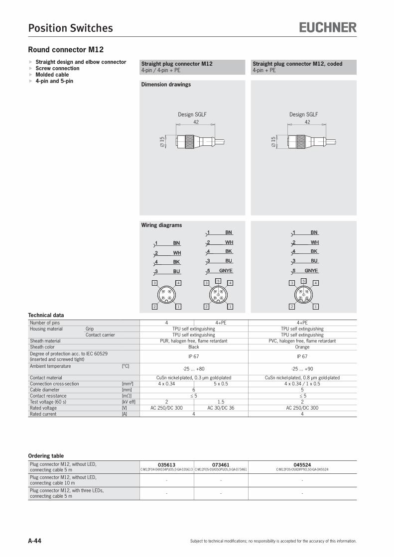
A-44
Position Switches
Subject to technical modifications; no responsibility is accepted for the accuracy of this information.
Round connector M12
Dimension drawings
Straight design and elbow connector Screw connection Molded cable 4-pin and 5-pin
Wiring diagrams
Straight plug connector M124-pin / 4-pin + PE
2 1
3 4
2
4
3
1 BN
WH
BK
BU
2 1
3 45
5 GNYE
2
4
3
1 BN
WH
BK
BU
Straight plug connector M12, coded4-pin + PE
2 1
3 45
5 GNYE
2
4
3
1 BN
WH
BK
BU
∅15
42
Design SGLF
∅15
42
Design SGLF
Technical dataNumber of pins 4 4+PE 4+PEHousing material Grip TPU self extinguishing TPU self extinguishing
Contact carrier TPU self extinguishing TPU self extinguishingSheath material PUR, halogen free, flame retardant PVC, halogen free, flame retardantSheath color Black OrangeDegree of protection acc. to IEC 60529 (inserted and screwed tight) IP 67 IP 67
Ambient temperature [°C] -25 ... +80 -25 ... +90
Contact material CuSn nickel-plated, 0.3 μm gold-plated CuSn nickel-plated, 0.8 μm gold-platedConnection cross-section [mm²] 4 x 0.34 5 x 0.5 4 x 0.34 / 1 x 0.5Cable diameter [mm] 6 5Contact resistance [mΩ] ≤ 5 ≤ 5Test voltage (60 s) [kV eff] 2 1.5 2Rated voltage [V] AC 250/DC 300 AC 30/DC 36 AC 250/DC 300Rated current [A] 4 4
Ordering tablePlug connector M12, without LED,connecting cable 5 m
035613C-M12F04-04X034PU05,0-GA-035613
073461C-M12F05-05X050PU05,0-GA-073461
045524C-M12F05-05XDIFPV0,50-GA-045524
Plug connector M12, without LED,connecting cable 10 m - - -
Plug connector M12, with three LEDs,connecting cable 5 m - - -

A-45
Position Switches
Subject to technical modifications; no responsibility is accepted for the accuracy of this information.
A
Right-angle plug connector M12, coded4-pin + PE
2 1
3 45
5 GNYE
2
4
3
1 BN
WH
BK
BU
27
38
∅15
Design SWLF
Right-angle plug connector M124-pin / 4-pin + PE
27
38
∅15
Design SWLF
Dimension drawings
Wiring diagrams
2 1
3 4
2
4
3
1 BN
WH
BK
BU
2 1
3 45
5 GNYE
2
4
3
1 BN
WH
BK
BU
4+PE 4 4+PE 4+PETPE TPU self extinguishing TPU self extinguishing
PBT GF, LIL 94 TPU self extinguishing TPU self extinguishingTPE (high-temperature PUR) PUR, halogen free, flame retardant PVC, halogen-free, flame retardant
Black Black Orange
IP 65 IP 67 IP 67
-30 ... +150 (for 2,000 h)(+125 for 8,000 h / +100 for 30,000 h) -25 ... +80 -25 ... +90
CuZn, CuBe CuSn nickel-plated, 0.3 μm gold-plated CuSn nickel-plated, 0.8 μm gold-plated5 x 0.34 4 x 0.34 5 x 0.5 5 x 0.5
5.5 6 5- ≤ 5 ≤ 5- 2 1.5 2
60 AC 250/DC 300 AC 30/DC 36 AC 250/DC 3004 4 4
136960C-M12F05-05X034PU05,0-GA-136960
035618C-M12F04-04X034PU05,0-GA-035618
073462C-M12F05-05X050PU05,0-GA-073462
045523C-M12F05-05XDIFPV05,0-GA-045523
136961C-M12F05-05X034PU10,0-GA-136961 - - -
- - -
Straight plug connector M12, A-coded4-pin + PE
2 1
3 45
5 GNYE
2
4
3
1 BN
WH
BK
BU
�14
44

A-46
Position Switches
Subject to technical modifications; no responsibility is accepted for the accuracy of this information.
Plug connector M12 with three LEDs4-pin
2 1
3 4
WHBN
BK 4
21
3BU
+
-
GN YE YE
3 LEDs27
38
∅15
Technical dataNumber of pins 4 4+PEHousing material Grip TPU self extinguishing TPE
Contact carrier TPU self extinguishing PBT GF, LIL 94Sheath material PUR, halogen-free, flame retardant TPE (high-temperature PUR)Sheath color Black BlackDegree of protection acc. to IEC 60529 (inserted and screwed tight) IP 67 IP 65
Ambient temperature [°C] -25 ... +80 -30 ... +150 (for 2,000 h)(+125 for 8,000 h / +100 for 30,000 h)
Contact material CuSn nickel-plated, 0.3 μm gold-plated CuZn, CuBeConnection cross-section [mm²] 4 x 0.34 5 x 0.34Cable diameter [mm] 5 5.5Contact resistance [mΩ] ≤ 5 -Test voltage (60 s) [kV eff] - -Rated voltage [V] DC 10 … 30 60Rated current [A] 4 4
Ordering tablePlug connector M12, without LED,connecting cable 5 m - 136962
C-M12F05-05X034PU05,0-GA-136962
Plug connector M12, without LED,connecting cable 10 m - 136963
C-M12F05-05X034PU10,0-GA-136963
Plug connector M12, with three LEDs,connecting cable 5 m
041091C-M12F04-04X034PU05,0-GA-041091 -
Plug connector M12, A-coded4-pin + PE
2 1
3 45
5 GNYE
2
4
3
1 BN
WH
BK
BU
27
35
�14

A-47
Position Switches
Subject to technical modifications; no responsibility is accepted for the accuracy of this information.
A
LED function displayOn request, versions with voltage ranges AC 110/230 V are available.
E M
BA
SW
Cable glandsMaterial nickel-plated brass, degree of protection IP 67
Trip rails/trip dogs
U-trip railsenable the trip dogs to be adjusted from the switch side. The trip dogs can be installed and adjusted quickly and easily in any location.
U-trip dogsare designed for usage in U-trip rails. They have an expansion plate clamp and enable precise adjustment, even when the limit switch is activated.
For detailed information see catalog for multiple limit switches.
Additional products
Operating voltage [V] Color Item Order no.
AC/DC 12 - 60
Red LE 060 rt 035495
Green LE 060 gr 035496
Yellow LE 060 ge 035497
Item Metric thread M
Cable outer diam-eter [mm]
A [mm]
B [mm]
E [mm]
SW [mm] Order no.
EKVM12/04 M12 x 1.5 4 - 6.5 20 5 15.5 14 086327
EKVM16/04 M16 x 1.5 4 - 6.5 20 6 20 18 086328
EKVM16/06 M16 x 1.5 6.5 - 9.5 20 6 20 18 086330
EKVM20/06 M20 x 1.5 6.5 - 9.5 20 6 24.4 22 077683

A-48
Position Switches
Subject to technical modifications; no responsibility is accepted for the accuracy of this information.
Appendix
Terms and explanations
Rated operating distance sn
The rated operating distance is a general vari-able used for identifying the operating distances. It does not take into account either the produc-tion tolerances or changes caused by external effects such as voltage and temperature.
Assured operating distance sa
The assured operating distance is the operating distance at which correct operation of the induc-tive switching element is guaranteed within the permissible operating conditions (temperature and voltage).The actuation distance is between 0 and 81% of the rated operating distance sn.
1,21 sn
0,81 sn
1,1 sn
0,9 sn
Test plate
Example tolerance
Active face
Inductive switching element
Total tolerance range sn
Hysteresis HThe hysteresis is the difference in distance terms between the ON point as the test plate approaches and the OFF point as it moves away from the active face of the inductive switching element.
Hysteresis
Axial approach
Opening curve
Closing curveSide approach
Repeat accuracy RThe repeat accuracy is the reproducibility of the real operating distance sr for two switching actions in succession within 8 hours at an oper-ating temperature of 23 ± 5 °C and an operating voltage of UB ± 5%.
Operating voltage UB
The operating voltage indicates the voltage range in which the inductive switching element functions reliably. The specified values represent limits without any tolerances. The values can be obtained by referring to the technical data for the switching element. In the case of two-wire switching elements, this is applicable only in series connection with the load.
Voltage drop Ud
The voltage drop is measured across the active output of the inductive switching element when the output is in the “active energized” condition and when the rated operating current Ie flows.
Rated operating current IeThe rated operating current is the nominal current that can load the inductive switching element in continuous operation.
Off-state current IrThe off-state current is the current that flows in the load circuit of an inductive switching element in the non-conducting condition. In practical terms, this current has to be taken into account only for two-wire switching elements.
Minimum operating current ImThe minimum operating current is the minimum current required for the function of a 2-wire switching element in active energized condition.
Switch-on current IKThe switch-on current is the maximum current that can flow in an AC 2-wire switching element for a particular period at the moment it is switched on. The details in the technical data are valid for 20 ms.
Switching frequency fThe switching frequency is the maximum possi-ble number of switching operations per second. It is determined according to IEC 60947-5-2, and is based on a mark-space ratio of 1:2. The switching frequency is a switch-specific variable and can be obtained by referring to the technical data for the switching element.
Ambient temperature TThe ambient temperature is the temperature range in which the reliable operation of the inductive switching element is guaranteed. This range is between - 25 and + 70 °C.
Temperature drift sThe temperature drift defines the offset in the switching point in μm/K on a change in the ambient temperature from -25 to +70 °C under otherwise constant measurement conditions.

A-49
Position Switches
Subject to technical modifications; no responsibility is accepted for the accuracy of this information.
A
The inductive switching elements are largely protected against external interference by use of various circuit techniques (suppressor circuits).For utilization category DC-13 the output is to be protected with a free-wheeling diode for inductive loads.
Short circuit and overload protectionThe inductive switching elements are designed so that short circuits cannot damage the out-puts. Pulsed short circuit protection is used.This means that the output transistor is switched off and on again in quick succession in the event of overloading or a short-circuit. In this way, it is possible to establish whether the fault is still present or has been rectified.
Suppressor circuits
Transient protectionEUCHNER proximity switches are protected against interference caused by the occurrence of inductive voltage peaks in accordance with IEC 801-4. The respective values are specified in the technical data. Testing is performed in ac-cordance with the stipulations in DIN VDE 0660, Part 208 and IEC 947-5-2.
Wire break safetyThe EUCHNER proximity switches with wire break safety are designed such that on a wire break on any connection, the switch does not output a spurious signal.
Reverse polarity protectionProtection against reverse polarization of the operating voltage.

Item Order no. Page Item Order no. Page
A-50
Item Index
Subject to technical modifications; no responsibility is accepted for the accuracy of this information.
Index by item designation
C-M12F04-04X034PU05,0-GA-035613 035613 A-44C-M12F04-04X034PU05,0-GA-035618 035618 A-45C-M12F04-04X034PU05,0-GA-041091 041091 A-46C-M12F05-05X034PU05,0-GA-136960 136960 A-45C-M12F05-05X034PU05,0-GA-136962 136962 A-46C-M12F05-05X034PU10,0-GA-136961 136961 A-45C-M12F05-05X034PU10,0-GA-136963 136963 A-46C-M12F05-05X050PU05,0-GA-073461 073461 A-44C-M12F05-05X050PU05,0-GA-073462 073462 A-45C-M12F05-05XDIFPV0,50-GA-045524 045524 A-44C-M12F05-05XDIFPV05,0-GA-045523 045523 A-45EGM12-1200C1791 075556 A-16EGM12-1200C1820 076464 A-16EGM12-1200C2463 128196 A-17EGM12-2500C2452 126384 A-17EGM12-4000C1791 076154 A-16EGM12SAM3C1868 077228 A-17EGM12SEM4 082205 A-17EGM12SEM4C1820 093733 A-17EGM8-1000C2396 119345 A-16EGT1/4A2000 001366 A-14EGT1/4A2000C2079 094982 A-15EGT1/4A2000C2137 102476 A-15EGT1/4A5000 001368 A-14EGT1/4ASEM4 033976 A-14EGT1/4ASEM4C1802 075644 A-14EGT1/4ASEM4C2088 095278 A-15EGT1/4ASEM4C2137 098071 A-15EGT1/4R2000 001371 A-14EGT1/4R5000 001372 A-14EGT1/4RSEM4 033982 A-14EGT1/4RSEM4C2088 104316 A-15EGT1/4RSEM4C2137 104372 A-15EGT1-2000 001732 A-20EGT1-5000 001733 A-20EGT11A2NSFM5 093352 A-12EGT11R2N50SAM4 084000 A-12EGT11R2NSFM5 091848 A-12EGT12A3000C2250 104223 A-10EGT12A5000 082201 A-10EGT12ARSEM4C1888 078483 A-13EGT12ASFM5 075426 A-11EGT12ASFM5C2083 095112 A-11EGT12R5000 078848 A-10EGT12RRSEM4C1888 079139 A-13EGT12RSFM5 075427 A-11EGT1M12-2000 092695 A-18EGT1M12-5000 093364 A-18EGT1M12SEM4 093365 A-18EGT1SEM4 019727 A-20EGT1SEM4C1613 054250 A-21EGT1SEM4C1832 077347 A-21EGT1SEM4C2221 102479 A-21EGT2-2000 001864 A-22EGT2-5000 001865 A-22EGT2SEM4 052504 A-22EGT4-10000 093967 A-23EGT4-2000 094339 A-23EGT4-5000 092026 A-23EGZ12-12-5000 094823 A-24EKVM12/04 086327 A-47EKVM16/04 086328 A-47EKVM16/06 086330 A-47
EKVM20/06 077683 A-47ENA10B050UP048LKK10-M ENA 086280 A-42ENA10B050UP048NKK10-M ENA 086099 A-42ESN10B050UP048LK05P-M ESN 088771 A-43ESN10B050UP048LKS01-M ESN 088770 A-43LE 060 ge 035497 A-47LE 060 gr 035496 A-47LE 060 rt 035495 A-47N01D550-M 084902 A-26N01D550-MC1526 091003 A-30N01D550-MC2018 085708 A-27N01D550SVM5-M 088623 A-27N01D550X5000-M 088978 A-27N01D562-M 087151 A-26N01D572-M 087162 A-26N01K550-M 084904 A-26N01K550-MC1526 091002 A-30N01K550-MC2018 089619 A-27N01K550SEM5-M 091258 A-30N01K550SVM5-M 088624 A-27N01K550X5000-M 088986 A-27N01K562-M 087152 A-26N01K572-M 087164 A-26N01R550-M 084903 A-26N01R550-MC1526 091001 A-30N01R550-MC2018 094856 A-27N01R550SEM5-M 091257 A-30N01R550SVM5-M 088622 A-27N01R550X5000-M 088982 A-27N01R562-M 085243 A-26N01R562SVM5-M 093426 A-27N01R572-M 087163 A-26N01R593-MC2445 128070 A-28N10D-M 086293 A-38N10K-M 088589 A-38N10R-M 086294 A-38N10RL-M 088587 A-38N11D-M 086298 A-39N11K-M 088585 A-39N11R-M 086313 A-39N11RL-M 086299 A-39N1AD502-M 079265 A-35N1AD502SVM5-M 087487 A-36N1AD502SVM5-MC1883 091471 A-36N1AD508-M 083886 A-34N1AD508-MC2222 103237 A-34N1AD508AM-M 090546 A-37N1AD514-M 083849 A-34N1AD514AM-MC2222 110462 A-35N1AD514SVM5-M 087603 A-35N1AK502-M 083847 A-35N1AK502SVM5-M 087489 A-36N1AK502SVM5-MC1883 087496 A-36N1AR502-M 078485 A-35N1AR502AM-M 090541 A-37N1AR502SVM5-M 087488 A-36N1AR508-M 083887 A-34N1AR508-MC2222 103221 A-34N1AR514-M 078487 A-34N1AR514AM-MC2222 103247 A-35N1AR514SVM5-M 087604 A-35N1ARL502-M 083848 A-37N1ARL508-M 087147 A-37

Item Order no. Page Item Order no. Page
A-51
Item Index
Subject to technical modifications; no responsibility is accepted for the accuracy of this information.
A
N1ARL514-M 087204 A-37N1AW508-M 087205 A-34N1AW508-MC2222 103222 A-34N1AW514-M 083850 A-34N1AW514SVM5-M 090743 A-35NB01D556-M 085245 A-31NB01D588-M 088584 A-31NB01K556-M 085247 A-31NB01R556-M 085246 A-31NB01R588-M 088583 A-31NB01R620-MC2276 102883 A-31SN01D553-M 085252 A-32SN01D558-M 085260 A-32SN01D558SVM5-M 088625 A-32SN01K553-M 085254 A-32SN01K558-M 085262 A-32SN01K558SVM5-M 088627 A-32SN01R553-M 085253 A-32SN01R558-M 085261 A-32SN01R558SVM5-M 088626 A-32SN01R558X2000-M 090515 A-33

Order no. Item Page Order no. Item Page
A-52
Item Index
Subject to technical modifications; no responsibility is accepted for the accuracy of this information.
Index by order number
001366 EGT1/4A2000 A-14001368 EGT1/4A5000 A-14001371 EGT1/4R2000 A-14001372 EGT1/4R5000 A-14001732 EGT1-2000 A-20001733 EGT1-5000 A-20001864 EGT2-2000 A-22001865 EGT2-5000 A-22019727 EGT1SEM4 A-20033976 EGT1/4ASEM4 A-14033982 EGT1/4RSEM4 A-14035495 LE 060 rt A-47035496 LE 060 gr A-47035497 LE 060 ge A-47035613 C-M12F04-04X034PU05,0-GA-035613 A-44035618 C-M12F04-04X034PU05,0-GA-035618 A-45041091 C-M12F04-04X034PU05,0-GA-041091 A-46045523 C-M12F05-05XDIFPV05,0-GA-045523 A-45045524 C-M12F05-05XDIFPV0,50-GA-045524 A-44052504 EGT2SEM4 A-22054250 EGT1SEM4C1613 A-21073461 C-M12F05-05X050PU05,0-GA-073461 A-44073462 C-M12F05-05X050PU05,0-GA-073462 A-45075426 EGT12ASFM5 A-11075427 EGT12RSFM5 A-11075556 EGM12-1200C1791 A-16075644 EGT1/4ASEM4C1802 A-14076154 EGM12-4000C1791 A-16076464 EGM12-1200C1820 A-16077228 EGM12SAM3C1868 A-17077347 EGT1SEM4C1832 A-21077683 EKVM20/06 A-47078483 EGT12ARSEM4C1888 A-13078485 N1AR502-M A-35078487 N1AR514-M A-34078848 EGT12R5000 A-10079139 EGT12RRSEM4C1888 A-13079265 N1AD502-M A-35082201 EGT12A5000 A-10082205 EGM12SEM4 A-17083847 N1AK502-M A-35083848 N1ARL502-M A-37083849 N1AD514-M A-34083850 N1AW514-M A-34083886 N1AD508-M A-34083887 N1AR508-M A-34084000 EGT11R2N50SAM4 A-12084902 N01D550-M A-26084903 N01R550-M A-26084904 N01K550-M A-26085243 N01R562-M A-26085245 NB01D556-M A-31085246 NB01R556-M A-31085247 NB01K556-M A-31085252 SN01D553-M A-32085253 SN01R553-M A-32085254 SN01K553-M A-32085260 SN01D558-M A-32085261 SN01R558-M A-32085262 SN01K558-M A-32085708 N01D550-MC2018 A-27086293 N10D-M A-38086294 N10R-M A-38
086298 N11D-M A-39086299 N11RL-M A-39086313 N11R-M A-39086327 EKVM12/04 A-47086328 EKVM16/04 A-47086330 EKVM16/06 A-47087147 N1ARL508-M A-37087151 N01D562-M A-26087152 N01K562-M A-26087162 N01D572-M A-26087163 N01R572-M A-26087164 N01K572-M A-26087204 N1ARL514-M A-37087205 N1AW508-M A-34087487 N1AD502SVM5-M A-36087488 N1AR502SVM5-M A-36087489 N1AK502SVM5-M A-36087496 N1AK502SVM5-MC1883 A-36087603 N1AD514SVM5-M A-35087604 N1AR514SVM5-M A-35088583 NB01R588-M A-31088584 NB01D588-M A-31088585 N11K-M A-39088587 N10RL-M A-38088589 N10K-M A-38088622 N01R550SVM5-M A-27088623 N01D550SVM5-M A-27088624 N01K550SVM5-M A-27088625 SN01D558SVM5-M A-32088626 SN01R558SVM5-M A-32088627 SN01K558SVM5-M A-32088978 N01D550X5000-M A-27088982 N01R550X5000-M A-27088986 N01K550X5000-M A-27089619 N01K550-MC2018 A-27090515 SN01R558X2000-M A-33090541 N1AR502AM-M A-37090546 N1AD508AM-M A-37090743 N1AW514SVM5-M A-35091001 N01R550-MC1526 A-30091002 N01K550-MC1526 A-30091003 N01D550-MC1526 A-30091257 N01R550SEM5-M A-30091258 N01K550SEM5-M A-30091471 N1AD502SVM5-MC1883 A-36091848 EGT11R2NSFM5 A-12092026 EGT4-5000 A-23092695 EGT1M12-2000 A-18093352 EGT11A2NSFM5 A-12093364 EGT1M12-5000 A-18093365 EGT1M12SEM4 A-18093426 N01R562SVM5-M A-27093733 EGM12SEM4C1820 A-17093967 EGT4-10000 A-23094339 EGT4-2000 A-23094823 EGZ12-12-5000 A-24094856 N01R550-MC2018 A-27094982 EGT1/4A2000C2079 A-15095112 EGT12ASFM5C2083 A-11095278 EGT1/4ASEM4C2088 A-15098071 EGT1/4ASEM4C2137 A-15102476 EGT1/4A2000C2137 A-15102479 EGT1SEM4C2221 A-21
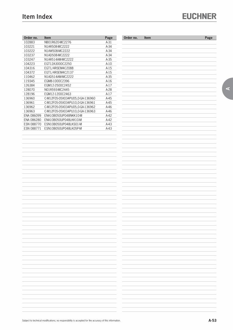
Order no. Item Page Order no. Item Page
A-53
Item Index
Subject to technical modifications; no responsibility is accepted for the accuracy of this information.
A
102883 NB01R620-MC2276 A-31103221 N1AR508-MC2222 A-34103222 N1AW508-MC2222 A-34103237 N1AD508-MC2222 A-34103247 N1AR514AM-MC2222 A-35104223 EGT12A3000C2250 A-10104316 EGT1/4RSEM4C2088 A-15104372 EGT1/4RSEM4C2137 A-15110462 N1AD514AM-MC2222 A-35119345 EGM8-1000C2396 A-16126384 EGM12-2500C2452 A-17128070 N01R593-MC2445 A-28128196 EGM12-1200C2463 A-17136960 C-M12F05-05X034PU05,0-GA-136960 A-45136961 C-M12F05-05X034PU10,0-GA-136961 A-45136962 C-M12F05-05X034PU05,0-GA-136962 A-46136963 C-M12F05-05X034PU10,0-GA-136963 A-46ENA 086099 ENA10B050UP048NKK10-M A-42ENA 086280 ENA10B050UP048LKK10-M A-42ESN 088770 ESN10B050UP048LKS01-M A-43ESN 088771 ESN10B050UP048LK05P-M A-43

A-54

B-1
B
Position Switches accordingto EN 50041
B

B-2

Contents
B-3
B
General information B-4
Advantages and features B-5
Application examples B-6
The position switch in detail B-7
Adjustment options B-8
Switching elements B-9
Wiring diagrams B-10
Plunger types B-11
Position switch with lever arm B-12
Series NG…/NZ… with cable entry M20 x 1.5
with plug connectors SR6 and SR11
with M12 plug connector SVM5
Position switch with adjustable lever arm B-18
Series NG…/NZ… with cable entry M20 x 1.5
with M12 plug connector SVM5
Position switch with pivoted lever arm B-22
Series NG… with cable entry M20 x 1.5
with M12 plug connector SVM5
Position switch with plunger actuator B-26
Series NG…/NZ… with cable entry M20 x 1.5
with plug connectors SR6 and SR11
with M12 plug connector SVM5
Position switch with spring actuator B-38
Series NG… with cable entry M20 x 1.5
with M12 plug connector SVM5
Special versions B-42
Spare parts and accessories B-45
Position Switches According to EN 50041

B-4
Position Switches According to EN 50041
Subject to technical modifications; no responsibility is accepted for the accuracy of this information.
General information
EUCHNER position switches are manufactured in accordance with Euro-pean standard EN 50041. Robust construction and the use of high quality corrosion resistant materials, precision finishing and degree of protection IP 67 according to IEC 60529 guarantee trouble-free and reliable operation under the toughest conditions.
Various EUCHNER position switch variants are also equipped as safety switches with switching elements whose NC contacts are positively opened by a rigid plunger, even if the switching element is damaged due to a broken spring or contact weld. Positively driven position switches are used in cases where a guarantee of machine and/or human safety is absolutely essential, e.g. final position limitation or an EMERGENCY STOP.
position switches – precise, reliable and versatile
Approvals for series NG… and NZ…
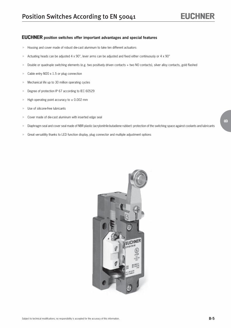
B-5
Position Switches According to EN 50041
Subject to technical modifications; no responsibility is accepted for the accuracy of this information.
B
position switches offer important advantages and special features
Housing and cover made of robust die-cast aluminum to take ten different actuators
Actuating heads can be adjusted 4 x 90°, lever arms can be adjusted and fixed either continuously or 4 x 90°
Double or quadruple switching elements (e.g. two positively driven contacts + two NO contacts), silver alloy contacts, gold flashed
Cable entry M20 x 1.5 or plug connection
Mechanical life up to 30 million operating cycles
Degree of protection IP 67 according to IEC 60529
High operating point accuracy to ± 0.002 mm
Use of silicone-free lubricants
Cover made of die-cast aluminum with inserted edge seal
Diaphragm seal and cover seal made of NBR plastic (acrylonitrile-butadiene rubber): protection of the switching space against coolants and lubricants
Great versatility thanks to LED function display, plug connector and multiple adjustment options

B-6
Position Switches According to EN 50041
Subject to technical modifications; no responsibility is accepted for the accuracy of this information.
Application examples for position switches from series NG… and NZ…

B-7
Position Switches According to EN 50041
Subject to technical modifications; no responsibility is accepted for the accuracy of this information.
B
Position switch in detailPlunger actuationThe plunger actuated versions allow the user a choice of six different designs.The hardened stainless steel plungers with tele-scopic action (positively driven position switches have rigid plungers) are precisely guided within the anodized actuator head, and are almost maintenance free.The approach direction of the actuator head can easily be changed by 90°.
Lever arm actuationDifferent types of actuators may be used for lever arm actuation. The stainless steel shaft is guided precisely through the housing.With the numerous adjusting options, a high degree of flexibility is given:
Approach direction adjustable by 8 x 90° Actuator direction for lever arm actuation adjustable by 4 x 90° Switches to the left or to the right, or on both sides
The housingWith their robust design, the die-cast alloy hous-ings have proven themselves highly resistant to corrosion even under the toughest conditions.The control cable can be connected with a cable gland M20 x 1.5 or via pre-wired plug connectors with straight or angled outlet. The right-angle plug connectors can be adjusted in seven directions around the longitudinal axis of the switch.
The diaphragm sealIn switches with plunger actuation, the plunger compartment and the interior of the switch are separated by a diaphragm seal made of NBR (acrylonitrile-butadiene rubber). Because of their outstanding technical properties, NBR materials are used wherever possible for all mechanical and systems engineering applications.The seal is permanently connected to the plunger, and the plunger – not the switching element – re-turns it to the free position by means of the plung-er return spring after every switching operation.Any build-up of pressure during plunger actuation is reliably prevented by a relief valve.The switching element is actuated by means of a metal cap pressed onto the seal.Switching point displacement (a logical conse-quence due to the high elasticity of the seal) is therefore completely eliminated.
The edge sealIn lever arm actuated switches, an edge seal protects the actuating mechanism and the switch chamber against dirt and dust. The edge seal, which is made of NBR, is resistant to all known coolants and lubricants.
Cable connectionsEUCHNER position switches according to EN 50041 undergo routine check tests for compliance with degree of protection IP 67 before delivery to the customer. To achieve this degree of protection, only high-quality metal cable glands with a captive sealing ring or the pre-wired straight or angled plug connectors must be used.
Function displayThe position switches can be fitted with a function display (LED) on request. Voltage ranges of 10 to 60 V AC/DC, 110 V AC and 230 V AC are available.

B-8
Position Switches According to EN 50041
Subject to technical modifications; no responsibility is accepted for the accuracy of this information.
Adjustment optionsActuator and approach directions
Lever arm HS = steel roller WO = domed plunger RG = plastic roller HB = plastic roller KO = ball plunger RS, RK, RL = steel roller
The large selection of actuator heads guarantees maximum flexibility and is suitable for a variety of applications. For example, the aluminum lever arm is used for high approach speeds and generous actuating mechanism tolerances. The chisel plunger with polish-ground surface is designed for a high operating point accuracy of ± 0.002 mm. The ball plungers can be actuated from a number of different directions.
Lever arm Straight actuator
After removal of the stainless steel fixing screws, the actuator heads can each be adjusted hori-zontally by 90°.
Adjustment option for the actuatorHorizontal adjustment 4 x 90°
The lever arm can be adjusted continuously for position switches without a safety function and by 45° for position switches with a safety function.
Vertical adjustment 4 x 90° or 8 x 45°
On delivery, the lever arm actuation is set to left and right switching. If necessary, it can be set to right switching or left switching only.
Adjustment option for switching direction
left/right switching right switching left switching (default setting)

B-9
Position Switches According to EN 50041
Subject to technical modifications; no responsibility is accepted for the accuracy of this information.
B
Switching elements Switching element 510 2) (without positively driven contact)Snap-action switching contact with one NC contact and one NO contact.Double gap, electrically isolated switching bridge, silver alloy gold flashed contact material, screw ter-minal with self-lifting clamp washers.Used for NG…
Switching element 511 2)
Snap-action switching contact with one positively driven contact and one NO contact.Double gap, electrically isolated contacts, silver alloy gold flashed contact material, screw terminal with self-lifting clamp washers.Used for NZ…
Switching element 528H 1) 3)
Slow-action switching contact with one positively driven contact and one NO contact.Double gap, electrically isolated H contact bridges for currents from 1 mA to 4 A, silver alloy gold flashed contact material, screw terminal with self-lifting clamp washers.Used for NZ…
Switching element 538H 1) 3)
Slow-action switching contact with two positively driven contacts.Double gap, electrically isolated H contact bridges for currents from 1 mA to 4 A, silver alloy gold flashed contact material, screw terminal with self-lifting clamp washers.Used for NZ…
1) Slow-action switching element The slow-action switching element has a switching contact that opens and closes depending on its actuation speed. 2) Snap-action switching element The snap-action switching element has a switching contact that opens and closes independently of its actuation speed.3) H-contact bridge The design properties of the H-contact bridge (H-shaped) ensure that these switching elements reliably switch currents from 1 mA to 4 A.
EUCHNER position switches marked with this symbol meet the IEC 60947-5-1 requirements for positively driven position switches. Safety switching elements marked with this symbol are not available as replacement switching elements.
Switching element 2131 H 3)
Slow-action switching contact with three positively driven contacts and one NO contact.Double gap, electrically isolated H contact bridges for currents from 1 mA to 4 A, silver alloy gold flashed contact material, screw terminal with self-lifting clamp washers.Used for NZ…
Switching element 3131 H 3)
Slow-action switching contact with two positively driven contacts and two NO contacts.Double gap, electrically isolated H contact bridges for currents from 1 mA to 4 A, silver alloy gold flashed contact material, screw terminal with self-lifting clamp washers.Used for NZ…
Switching element 2121 H 3)
Slow-action switching contact with four positively driven contacts.Double gap, electrically isolated H contact bridges for currents from 1 mA to 4 A, silver alloy gold flashed contact material, screw terminal with self-lifting clamp washers.Used for NZ…
4142
33 34
2122
1112
4142
34
2122
13 14
33
4142
31
2122
1112
32
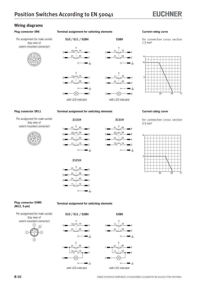
B-10
Position Switches According to EN 50041
Subject to technical modifications; no responsibility is accepted for the accuracy of this information.
Wiring diagrams
Plug connector SVM5(M12, 5-pin)
Pin assignment for male socket(top view of
switch mounted connector)
Terminal assignment for switching elements
4
31
2
Plug connector SR6
Pin assignment for male socket(top view of
switch mounted connector)
Terminal assignment for switching elements
510 / 511 / 528H 538H
with LED indicator
3
1
4
2
13
21
14
22
5 6
3
1
4
2
13
21
14
22
3
1
4
2
11
21
12
22
5 6
3
1
4
2
11
21
12
22
with LED indicator
for connection cross section 1.5 mm²
A
10
5
50 90 °C
Current rating curve
Plug connector SR11
Pin assignment for male socket(top view of
switch mounted connector)
Terminal assignment for switching elements
7
5
3
1
8
6
4
2
41
33
21
11
42
34
22
12
7
5
3
1
8
6
4
2
41
33
21
13
42
34
22
14
7
5
3
1
8
6
4
2
41
31
21
11
42
32
22
12
2131H 3131H
2121H
for connection cross section 0.5 mm²
A
5
50 90 °C
Current rating curve
510 / 511 / 528H 538H
3
1
4
2
13
21
14
22
3
1
4
2
11
21
12
22
1 2
4
21
13
22
14
3
with LED indicator
1 2
4
21
11
22
12
3
with LED indicator

B-11
Position Switches According to EN 50041
Subject to technical modifications; no responsibility is accepted for the accuracy of this information.
B
Plunger typesPlungers for position switches are made of stainless steel and are ex-tremely accurate. In conjunction with a plunger guide with a special surface finish, operation is extremely reliable and maintenance-free even beyond the guaranteed mechanical life.
There are two different types of actuating systems, depending on the application. For standard applications, the plunger is fitted with a telescopic device. With this system, the plunger can be depressed to the reference surface without damaging the switching element.
Instead of this telescopic plunger, position switches with safety function (with safety switching element) have a rigid plunger to ensure positive driving according to IEC 60947-5-1. This means that the contact point will be reliably opened in the event of mechanical failure of the switching element – e.g. owing to the failure of a contact spring or contact weld resulting from an overload.
FreePosition
OperatingPoint
FinalPosition
ResetPoint
Total TravelIdle TravelResetTravel
MovementDifferential
Over TravelPre-travel
Plunger travel
Plunger types
Depending on the technical requirements, four different plunger types (chisel, roller, ball and domed plungers) are used.
Chisel plunger Hardened and polish ground. Operating point accuracy to ± 0.002 mm 1). Max. approach speed of 10 m/min. With its high operating point accuracy, the
chisel plunger is ideal for setting reference points for moderate approach speeds.
Roller plunger Hardened roller. Operating point accuracy to ± 0.01 mm 1). Max. approach speed of 50 m/min. The roller plunger is suitable for higher approach
speeds. For very high approach speeds and long travel distances, roller plungers with a protected bearing can be offered on request.
Ball plunger Ball hardened. Operating point accuracy to ± 0.01 mm 1). Max. approach speed of 10 m/min. This plunger can be actuated from a number of
different directions. It must not be used in conjunction with safety
switching elements!
Domed plunger Hardened and polished ground. Operating point accuracy to ± 0.002 mm 1). Max. approach speed of 10 m/min. This plunger can be actuated from a number of
different directions. For use in conjunction with safety switching
elements!
Extended rollerplunger Robust roller plunger for medium approach
speeds.
The pictures show the various positions of the plunger actuated by a trip dog.The precise values for the relevant design are shown in the technical data.
Travel ratio for plunger/trip dog
All the plunger travel data shown in the technical data refers to axial ac-tuation. The travel for radial actuation with angled trip dogs is increase, and this must be calculated.
1) The reproducible operating point accuracy refers to the axial travel of the plunger after the switching element ES 502 E has been run in with approx. 2,000 operating cycles.

B-12
Position Switches According to EN 50041
Subject to technical modifications; no responsibility is accepted for the accuracy of this information.
Position switch series NG1…/NZ1…
Dimension drawing Switching elements 510 Snap-action switching contact
1 NC + 1 NO 511 Snap-action switching contact
1 NC + 1 NO 528H Slow-action switching contact
1 NC + 1 NO 538H Slow-action switching contact
2 NC 2131H Slow-action switching contact
3 NC + 1 NO 3131H Slow-action switching contact
2 NC + 2 NO(further information: see page B-9)
LED function displayA red function display LED is available for the following voltage ranges:
12-60 V AC/DC L060110 V AC ±15% L110230 V AC ±15% (on request) L220
Adjustment options (see page B-8) Horizontal 4 x 90° Vertical 8 x 45°
Switching directionSwitches to the right, left or both sides (see page B-8).M20x1,5
30° max.
52+
1
ES511 ES528H
ES538H SK2131H SK3131H
ES510
A
B
C A
B
C
A
B
A
A
B
AA
B
AAA
B
Roller lever arm HB (plastic roller) HS (steel roller)
Cable entry M20 x 1.5
Travel diagrams Contacts A Operating point open B End position
closed C Reset point If damaged or worn, safety switches must be replaced as a unit.
Notes on installation for position switches with safety switching elements
To achieve the positively driven travel, the dimension 52 +1 must be maintained by the trip dog. Actuating elements such as cam approach guides must be positively mounted in accordance with EN 1088, i.e. riveted, welded or otherwise secured against becoming loose.
NG… NZ…
1)
1) Not applicable to NZ with switching element 511.
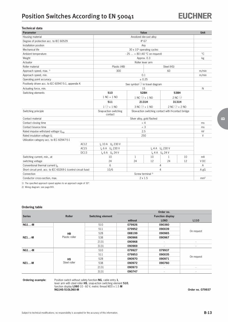
B-13
Position Switches According to EN 50041
Subject to technical modifications; no responsibility is accepted for the accuracy of this information.
B
Technical dataParameter Value UnitHousing material Anodized die-cast alloy
Degree of protection acc. to IEC 60529 IP 67
Installation position Any
Mechanical life 30 x 106 operating cycles
Ambient temperature - 25 … + 80 (-40 °C on request) °C
Weight Approx. 0.3 kg
Actuator Roller lever arm
Roller material Plastic (HB) Steel (HS)
Approach speed, max. 1) 300 60 m/min
Approach speed, min. 0.1 m/min
Operating point accuracy ± 0.25
Positively driven acc. to IEC 60947-5-1, appendix K See symbol in travel diagram
Actuating force, min. 15 N
Switching elements 510 528H 538H1 NC + 1 NO 1 NC + 1 NO 2 NC
511 2131H 3131H
1 + 1 NO 3 NC + 1 NO 2 NC + 2 NO
Switching principle Snap-action switching contact
Slow-action switching contact with H-contact bridge
Contact material Silver alloy, gold flashed
Contact closing time < 4 ms
Contact bounce time < 3 ms
Rated impulse withstand voltage Uimp 2.5 kV
Rated insulation voltage Ui 250 V
Utilization category acc. to IEC 60947-5-1
AC12 Ie 10 A Ue 230 V -
AC15 Ie 6 A Ue 230 V Ie 4 A Ue 230 V
DC13 Ie 6 A Ue 24 V Ie 4 A Ue 24 V
Switching current, min., at 10 1 10 1 10 mA
switching voltage 24 24 12 24 12 V DC
Conventional thermal current Ith 6 4 A
Short circuit prot. acc. to IEC 60269-1 (control circuit fuse) 10/6 4 A gG
Connection Screw terminal 2)
Conductor cross-section, max. 2 x 1.5 mm²
1) The specified approach speed applies to an approach angle of 30°.
2) Wiring diagram: see page B-9.
Ordering table
Series Roller Switching elementOrder no.
Function displaywithout L060 L110
NG1…-M
HBPlastic roller
510 079926 090360
On request
NZ1…-M
511 079952 090039528 088199 090965538 090966 090967
2131 090968 - -
3131 090969 - -
NG1…-M
HSSteel roller
510 079927 079937
On request
NZ1…-M
511 079953 090035528 090970 090971538 090972 090760
2131 090973 - -
3131 090747 - -
Ordering example: Position switch without safety function NG, cable entry 1,lever arm with steel roller HS, snap-action switching element 510,function display L060 10 - 60 V, metric thread M20 x 1.5 MNG1HS-510L060-M Order no. 079937

B-14
Position Switches According to EN 50041
Subject to technical modifications; no responsibility is accepted for the accuracy of this information.
Position switch series NG2…/NZ2…
Switching elements 510 Snap-action switching contact
1 NC + 1 NO 511 Snap-action switching contact
1 NC + 1 NO 528H Slow-action switching contact
1 NC + 1 NO 538H Slow-action switching contact
2 NC 2131H Slow-action switching contact
3 NC + 1 NO 3131H Slow-action switching contact
2 NC + 2 NO(further information: see page B-9)
LED function displayA red function display LED is available for the following voltage ranges:
12-60 V AC/DC (standard) L060110 V AC ±15% (on request) L110230 V AC ±15% (on request) L220
Adjustment options (see page B-8) Horizontal 4 x 90° Vertical 8 x 45°
Switching directionSwitches to the right, left or both sides (see page B-8).
SR6WF SR6EF/SR11EF SR11WF30° m
ax.
52+
1
ES511 ES528H
ES538H SK2131H SK3131H
ES510
A
B
C A
B
C
A
B
A
A
B
AA
B
AAA
B
Inse
rted
Inse
rted
Inse
rted
Roller lever arm HB (plastic roller) HS (steel roller)
Plug connectors SR6 and SR11
Dimension drawing
Travel diagrams Contacts A Operating point open B End position
closed C Reset point If damaged or worn, safety switches must be replaced as a unit.
Notes on installation for position switches with safety switching elements
To achieve the positively driven travel, the dimension 52 +1 must be maintained by the trip dog. Actuating elements such as cam approach guides must be positively mounted in accordance with EN 1088, i.e. riveted, welded or otherwise secured against becoming loose.
NG… NZ…
1)
1) Not applicable to NZ with switching element 511.

B-15
Position Switches According to EN 50041
Subject to technical modifications; no responsibility is accepted for the accuracy of this information.
B
Technical dataParameter Value UnitHousing material Anodized die-cast alloy
Degree of protection acc. to IEC 60529 IP 65
Installation position Any
Mechanical life 30 x 106 operating cycles
Ambient temperature - 25 … + 80 (-40 °C on request) °C
Weight Approx. 0.3 kg
Actuator Roller lever arm
Roller material Plastic (HB) Steel (HS)
Approach speed, max. 1) 300 60 m/min
Approach speed, min. 0.1 m/min
Operating point accuracy ± 0.25
Positively driven acc. to IEC 60947-5-1, appendix K See symbol in travel diagram
Actuating force, min. 15 N
Switching elements 510 528H 538H1 NC + 1 NO 1 NC + 1 NO 2 NC
511 2131H 3131H
1 + 1 NO 3 NC + 1 NO 2 NC + 2 NO
Switching principle Snap-action switching cont. Slow-action switching contact with H-contact bridge
Contact material Silver alloy, gold flashed
Contact closing time < 4 ms
Contact bounce time < 3 ms
Switching current, min., at 10 1 10 1 10 mA
switching voltage 24 24 12 24 12 V DC
Conventional thermal current Ith 6 4 A
Short circuit prot. acc. to IEC 60269-1 (control circuit fuse) 6 4 A gG
Connection Plug connector according to DIN 43651 2)
Rated impulse withstand voltage Uimp
kVWith plug connector SR6 2.5
With plug connector SR11 1.5
Rated insulation voltage Ui
VWith plug connector SR6 250
With plug connector SR11 50
Utilization category acc. to IEC 60947-5-1
With plug connector SR6 AC15 Ie 6 A Ue 230 V Ie 4 A Ue 230 V
DC13 Ie 6 A Ue 24 V Ie 4 A Ue 24 V
With plug connector SR11 AC15 Ie 4 A Ue 50 V
DC13 Ie 4 A Ue 24 V
1) The specified approach speed applies to an approach angle of 30°.
2) Wiring diagram: see page B-10.
Ordering table
Series Roller Switching element
Order no.Plug connector/function display
SR6 SR6 SR11 SR11without L060 without L110
NG2...
HBPlastic roller
510 089088 089089 - -
NZ2…
511 089091 089092 - -
528 090845 090846 - -
538 090847 090848 - -
2131 - - - 0901363131 - - - 090137
NG2...
HSSteel roller
510 090851 089090 - -
NZ2…
511 089093 089094 - -
528 090852 088196 - -
538 090853 090854 - -
2131 - - - 0901463131 - - 090856 -
Ordering example: Position switch without safety function NG, plug connector 2,lever arm with steel roller HS, snap-action switching element 510,function display L060 10 - 60 VNG2HS-510L060
Order no. 089090

B-16
Position Switches According to EN 50041
Subject to technical modifications; no responsibility is accepted for the accuracy of this information.
Position switch series NG2…/NZ2…
Switching elements 510 Snap-action switching contact
1 NC + 1 NO 511 Snap-action switching contact
1 NC + 1 NO 528H Slow-action switching contact
1 NC + 1 NO 538H Slow-action switching contact
2 NC (further information: see page B-9)
LED function displayAvailable on request
Adjustment options (see page B-8) Horizontal 4 x 90° Vertical 8 x 45°
Switching directionSwitches to the right, left or both sides (see page B-8).
ES511 ES528H
ES538H
ES510
A
B
C A
B
C
A
B
A
A
B
6
42
32
30° max.
64
56
74
100
5,3
7,3
5,3
22
60±
0,1
22
45°
16
40 +1
30 ±0,1
26,5
31
32
ø18
52+
1
Guide lug aligned
Right-angle plug connector:male socket adjustable max. 270°.Default setting: cable outlet to the right.
Roller lever arm HB (plastic roller) HS (steel roller)
Plug connector M12/SVM5
Dimension drawing
Travel diagrams Contacts A Operating point open B End position
closed C Reset point If damaged or worn, safety switches must be replaced as a unit.
Notes on installation for position switches with safety switching elements
To achieve the positively driven travel, the dimension 52 +1 must be maintained by the trip dog. Actuating elements such as cam approach guides must be positively mounted in accordance with EN 1088, i.e. riveted, welded or otherwise secured against becoming loose.
NG… NZ…
1)
1) Not applicable to NZ with switching element 511.

B-17
Position Switches According to EN 50041
Subject to technical modifications; no responsibility is accepted for the accuracy of this information.
B
Ordering table
Series Roller Switching elementOrder no.
Plug connectorSVM5
NG2...
HBPlastic roller
510 088631
NZ2…511 090861528 090864538 090862
NG2...
HSSteel roller
510 090866
NZ2…511 090867528 090868538 090869
Ordering example: Position switch without safety function NG, plug connector 2,lever arm with steel roller HS, snap-action switching element 510,M12 male socket with PE connection SVM5NG2HS-510SVM5 Order no. 090866
Technical dataParameter Value UnitHousing material Anodized die-cast alloy
Degree of protection acc. to IEC 60529 IP 67
Installation position Any
Mechanical life 30 x 106 operating cycles
Ambient temperature - 25 … + 80 (-40 °C on request) °C
Weight Approx. 0.3 kg
Actuator Roller lever arm
Roller material Plastic (HB) Steel (HS)
Approach speed, max. 1) 300 60 m/min
Approach speed, min. 0.1 m/min
Operating point accuracy ± 0.25
Positively driven acc. to IEC 60947-5-1, appendix K See symbol in travel diagram
Actuating force, min. 15 N
Switching elements 510 528H 538H1 NC + 1 NO 1 NC + 1 NO 2 NC
511
1 + 1 NO
Switching principle Snap-action switching contact
Slow-action switching contact with H-contact bridge
Contact material Silver alloy, gold flashed
Contact closing time < 4 ms
Contact bounce time < 3 ms
Rated impulse withstand voltage Uimp 1.5 kV
Rated insulation voltage Ui 50 V
Utilization category acc. to IEC 60947-5-1
with plug connector SVM5 AC15 Ie 4 A Ue 30 V Ie 4 A Ue 30 V
DC13 Ie 4 A Ue 24 V Ie 4 A Ue 24 V
Switching current, min., at 10 1 10 1 10 mA
switching voltage 24 24 12 24 12 V DC
Conventional thermal current Ith 4 4 A
Short circuit prot. acc. to IEC 60269-1 (control circuit fuse) 4 4 A gG
Connection Plug connector M12 2)
1) The specified approach speed applies to an approach angle of 30°.
2) Wiring diagram: see page B-10.

B-18
Position Switches According to EN 50041
Subject to technical modifications; no responsibility is accepted for the accuracy of this information.
Position switch series NG1…/NZ1…
Switching elements 510 Snap-action switching contact
1 NC + 1 NO 511 Snap-action switching contact
1 NC + 1 NO 528H Slow-action switching contact
1 NC + 1 NO 538H Slow-action switching contact
2 NC 2131H Slow-action switching contact
3 NC + 1 NO 3131H Slow-action switching contact
2 NC + 2 NO(further information: see page B-9)
LED function displayA red function display LED is available for the following voltage ranges:
12-60 V AC/DC (standard) L060110 V AC ±15% (on request) L110230 V AC ±15% (on request) L220
Adjustment options (see page B-8) Horizontal 4 x 90° Vertical 8 x 45°
Switching directionSwitches to the right, left or both sides (see page B-8).
M20x1,5
74
100
5,3
5,3
22
60±
0,1
40 +1
30 ±0,1
7,3
28 -
75
NG... NZ...
66
59
30° max.
ES511 ES528H
ES538H SK2131H SK3131H
ES510
A
B
C A
B
C
A
B
A
A
B
AA
B
AAA
B
45° +5°
45° +5°45° +5°45° +5°
45° +5°45° +5°
VB / VS PB / PS
Adjustable roller lever arm VB (plastic) / PB (plastic roller) VS (steel roller) / PS (steel roller)
Cable entry M20 x 1.5 (plug connector on request)
Dimension drawing
Travel diagrams Contacts A Operating point open B End position
closed C Reset point If damaged or worn, safety switches must be replaced as a unit.
Notes on installation for position switches with safety switching elements
To achieve the positively driven travel, the trip dog must be mounted so that it actuates the lever arm to the angle 45°+5° . Actuating elements such as cam approach guides must be positively mounted in accordance with EN 1088, i.e. riveted, welded or otherwise secured against becoming loose.
NG… NZ…
1)
1) Not applicable to NZ with switching element 511.

B-19
Position Switches According to EN 50041
Subject to technical modifications; no responsibility is accepted for the accuracy of this information.
B
Technical dataParameter Value UnitHousing material Anodized die-cast alloy
Degree of protection acc. to IEC 60529 IP 67
Installation position Any
Mechanical life 30 x 106 operating cycles
Ambient temperature - 25 … + 80 (-40 °C on request) °C
Weight Approx. 0.3 kg
Actuator Adjustable roller lever arm
Roller material Plastic (VB) Plastic (PB) Steel (VS) Steel (PS)
Approach speed, max. 1) 120 120 30 30 m/min
Approach speed, min. 0.5 m/min
Positively driven acc. to IEC 60947-5-1, appendix K See symbol in travel diagram
Actuating force, min. 15 N
Switching elements 510 528H 538H1 NC + 1 NO 1 NC + 1 NO 2 NC
511 2131H 3131H
1 + 1 NO 3 NC + 1 NO 2 NC + 2 NO
Switching principle Snap-action switching contact
Slow-action switching contact with H-contact bridge
Contact material Silver alloy, gold flashed
Contact closing time < 4 ms
Contact bounce time < 3 ms
Rated impulse withstand voltage Uimp 2.5 kV
Rated insulation voltage Ui 250 V
Utilization category acc. to IEC 60947-5-1
AC12 Ie 10 A Ue 230 V -
AC15 Ie 6 A Ue 230 V Ie 4 A Ue 230 V
DC13 Ie 6 A Ue 24 V Ie 4 A Ue 24 V
Switching current, min., at 10 1 10 1 10 mA
switching voltage 24 24 12 24 12 V DC
Conventional thermal current Ith 6 4 A
Short circuit prot. acc. to IEC 60269-1 (control circuit fuse) 10/6 4 A gG
Connection Screw terminal 2)
Conductor cross-section, max. 2 x 1.5 mm²
1) The specified approach speed applies to an approach angle of 30°.
2) Wiring diagram: see page B-9.
Ordering table
Series Roller Switching elementOrder no.
Function displaywithout L060
NG1…-M
VBPlastic roller 510 086322 091288
VSSteel roller 510 079934 090599
NZ1…-M
PBPlastic roller
511 088618 094753528 090870
On request538 090871
2131 090872 -
3131 090873 -
PSSteel roller
511 088613 -
528 090874 090430538 090875 -
2131 090876 -
3131 090877 -
Ordering example: Position switch with safety function NZ, cable entry 1,adjustable lever arm with plastic roller PB,snap-action switching element 511, metric thread M20 x 1.5 MNZ1PB-511-M Order no. 088613

B-20
Position Switches According to EN 50041
Subject to technical modifications; no responsibility is accepted for the accuracy of this information.
Position switch series NZ2…
Switching elements 511 Snap-action switching contact
1 NC + 1 NO(further information: see page B-9)
LED function displayA yellow function display is available for the following voltage ranges:
12-60 V AC/DC (standard) L060
Adjustment options (see page B-8) Horizontal 4 x 90° Vertical 8 x 45°
Switching directionSwitches to the right, left or both sides (see page B-8).
ES511
A
B
C
45° +5°
28
30 ±0,1
40 0+1
22 7,3
5,3
100
74
5,3
22
40,55365
,578
60±
0,1
18
6
59
66
M12x1
16
M20x1,5
32 42
45°
26,5
31
Guide lug aligned
Right-angle plug connector:male socket adjustable max. 270°.Default setting: cable outlet to the right.
Adjustable roller lever arm PB (plastic roller) PS (steel roller)
Plug connector M12/SVM5
Dimension drawing
Travel diagrams Contacts A Operating point open B End position
closed C Reset point If damaged or worn, safety switches must be replaced as a unit.
Notes on installation for position switches with safety switching elements
To achieve the positively driven travel, the trip dog must be mounted so that it actuates the lever arm to the angle 45°+5° . Actuating elements such as cam approach guides must be positively mounted in accordance with EN 1088, i.e. riveted, welded or otherwise secured against becoming loose.

B-21
Position Switches According to EN 50041
Subject to technical modifications; no responsibility is accepted for the accuracy of this information.
B
Technical dataParameter Value UnitHousing material Anodized die-cast alloy
Degree of protection acc. to IEC 60529 IP 67
Installation position Any
Mechanical life 30 x 106 operating cycles
Ambient temperature - 25 … + 80 (-40 °C on request) °C
Weight Approx. 0.3 kg
Actuator Adjustable roller lever arm
Roller material Plastic (PB) Steel (PS)
Approach speed, max. 1) 120 30 m/min
Approach speed, min. 0.5 m/min
Positively driven acc. to IEC 60947-5-1, appendix K See symbol in travel diagram
Actuating force, min. 15 N
Switching elements 511
1 + 1 NO
Switching principle Snap-action switching contact
Contact material Silver alloy, gold flashed
Contact closing time < 4 ms
Contact bounce time < 3 ms
Rated impulse withstand voltage Uimp 1.5 kV
Rated insulation voltage Ui 50 V
Utilization category acc. to IEC 60947-5-1
with plug connector SVM5 AC15 Ie 4 A Ue 30 V
DC13 Ie 4 A Ue 24 V
Switching current, min., at switching voltage
10 mA
24 V DC
Conventional thermal current Ith 4 A
Short circuit prot. acc. to IEC 60269-1 (control circuit fuse) 4 A gG
Connection Plug connector M12 2)
1) The specified approach speed applies to an approach angle of 30°.
2) Wiring diagram: see page B-10.
Ordering table
Series Roller Switching elementOrder no.
Function displaywithout L060
NZ2…
PBPlastic roller 511 - 098646
PSSteel roller 511 106697 098645
Ordering example: Position switch with safety function NZ, plug connector 2,adjustable lever arm with steel roller PS,snap-action switching element 511, M12 male socket with PE connection SVM5NZ2PS-511SVM5 Order no. 106697

B-22
Position Switches According to EN 50041
Subject to technical modifications; no responsibility is accepted for the accuracy of this information.
Position switch series NG1…
Switching elements 510 Snap-action switching contact
1 NC + 1 NO(further information: see page B-9)
LED function displayA red function display LED is available for the following voltage ranges:
12-60 V AC/DC (standard) L060110 V AC ±15% (on request) L110230 V AC ±15% (on request) L220
Adjustment optionsHorizontal and vertical 4 x 90° (see page B-8).
Switching directionSwitches to the right, left or both sides (see page B-8).
7,3
60±
0,1
2007
74
100 5,3
2252
∅ 6
5,3
30 ±0,1
40 +1
16
32
42
M20x1,5
75°
22° ±3°
A
B
C
Pivoted lever arm SB (plastic rod) SM (aluminum rod)
Cable entry M20 x 1.5 (plug connector on request)
Dimension drawing
Travel diagrams Contacts A Operating point open B End position
closed C Reset point

B-23
Position Switches According to EN 50041
Subject to technical modifications; no responsibility is accepted for the accuracy of this information.
B
Technical dataParameter Value UnitHousing material Anodized die-cast alloy
Degree of protection acc. to IEC 60529 IP 67
Installation position Any
Mechanical life 30 x 106 operating cycles
Ambient temperature - 25 … + 80 (-40 °C on request) °C
Weight Approx. 0.3 kg
Actuator Pivoted lever arm
Roller material Plastic (SB) Aluminum (SM)
Approach speed, max. 60 m/min
Approach speed, min. 0.5 m/min
Operating point accuracy ± 1 °
Actuating force, min. 15 N
Switching elements 5101 NC + 1 NO
Switching principle Snap-action switching contact
Contact material Silver alloy, gold flashed
Contact closing time < 4 ms
Contact bounce time < 3 ms
Rated impulse withstand voltage Uimp 2.5 kV
Rated insulation voltage Ui 250 V
Utilization category acc. to IEC 60947-5-1
AC12 Ie 10 A Ue 230 V
AC15 Ie 6 A Ue 230 V
DC13 Ie 6 A Ue 24 V
Switching current, min., at 10 mA
switching voltage 24 V DC
Conventional thermal current Ith 6 A
Short circuit prot. acc. to IEC 60269-1 (control circuit fuse) 10/6 A gG
Connection Screw terminal 1)
Conductor cross-section, max. 2 x 1.5 mm²
1) Wiring diagram: see page B-9.
Ordering table
Series Actuator Switching elementOrder no.
Function displaywithout L060
NG1…-M
SBPlastic rod 510 088609 090577
SMAluminum rod 510 079932 090575
Ordering example: Position switch without safety function NG, cable entry 1,pivoted lever arm with plastic rod SB, snap-action switching element 510,function display L060 10 - 60 V, metric thread M20 x 1.5 MNG1SB-510L060-M Order no. 090577

B-24
Position Switches According to EN 50041
Subject to technical modifications; no responsibility is accepted for the accuracy of this information.
Position switch series NG2…
Switching elements 510 Snap-action switching contact
1 NC + 1 NO(further information: see page B-9)
LED function displayAvailable on request
Adjustment optionsHorizontal and vertical 4 x 90° (see page B-8).
Switching directionSwitches to the right, left or both sides (see page B-8).
26,5
31
5,3
22
100
74
22
40 0+1
5,3
7,3
30 ±0,1
7
22° ±3°
75°
60±
0,1
52
200
16
64
6
M20x1,5
32
42
45°
Guide lug aligned
Right-angle plug connector:male socket adjustable max. 270°.Default setting: cable outlet to the right.
Pivoted lever arm SB (plastic rod) SM (aluminum rod)
Plug connector M12/SVM5
Dimension drawing
Travel diagrams Contacts A Operating point open B End position
closed C Reset point
A
B
C

B-25
Position Switches According to EN 50041
Subject to technical modifications; no responsibility is accepted for the accuracy of this information.
B
Technical dataParameter Value UnitHousing material Anodized die-cast alloy
Degree of protection acc. to IEC 60529 IP 67
Installation position Any
Mechanical life 30 x 106 operating cycles
Ambient temperature - 25 … + 80 (-40 °C on request) °C
Weight Approx. 0.3 kg
Actuator Pivoted lever arm
Roller material Plastic (SB) Aluminum (SM)
Approach speed, max. 60 m/min
Approach speed, min. 0.5 m/min
Operating point accuracy ± 1 °
Actuating force, min. 15 N
Switching elements 5101 NC + 1 NO
Switching principle Snap-action switching contact
Contact material Silver alloy, gold flashed
Contact closing time < 4 ms
Contact bounce time < 3 ms
Rated impulse withstand voltage Uimp 1.5 kV
Rated insulation voltage Ui 50 V
Utilization category acc. to IEC 60947-5-1
Plug connector SVM5 AC15 Ie 4 A Ue 30 V
DC13 Ie 4 A Ue 24 V
Switching current, min., at 10 mA
switching voltage 24 V DC
Conventional thermal current Ith 4 A
Short circuit prot. acc. to IEC 60269-1 (control circuit fuse) 4 A gG
Connection Plug connector M12 1)
1) Wiring diagram: see page B-10.
Ordering table
Series Actuator Switching elementOrder no.
Plug connectorSVM5
NG2...
SBPlastic rod 510 091303
SMAluminum rod 510 094059
Ordering example: Position switch without safety function NG, plug connector 2,pivoted lever arm with plastic rod SB, snap-action switching element 510,M12 male socket with PE connection SVM5NG2SB-510SVM5 Order no. 091303

B-26
Position Switches According to EN 50041
Subject to technical modifications; no responsibility is accepted for the accuracy of this information.
Position switch series NG1…/NZ1…
Switching elements 510 Snap-action switching contact
1 NC + 1 NO 511 Snap-action switching contact
1 NC + 1 NO 528H Slow-action switching contact
1 NC + 1 NO 538H Slow-action switching contact
2 NC 2131H Slow-action switching contact
3 NC + 1 NO 3131H Slow-action switching contact
2 NC + 2 NO(further information: see page B-9)
LED function displayA red function display LED is available for the following voltage ranges:
12-60 V AC/DC (standard) L060110 V AC ±15% (on request) L110230 V AC ±15% (on request) L220
Adjustment optionsHorizontal 4 x 90° (see page B-8).
To achieve the positively driven travel, the dimension 31 +1 must be maintained by the trip dog. Actuating elements such as cam approach guides must be positively mounted in accordance with EN 1088, i.e. riveted, welded or otherwise secured against becoming loose.
74
5,3
60±
0,1
40 +1
30 ±0,1
16
32
42
M20x1,5
7,3
5,3
97
R4
31+
1
37±
1∅ 10
16
30° max.
31+
1
Posi
tivel
y dr
iven
Free
pos
ition
01234
6
13-1
421
-22
13-1
421
-22
ES511
mm
13-1
421
-22
11-1
221
-22
ES528H ES538H
01234
6mm mm
6
43210
SK2131H
41-4
233
-34
21-2
211
-12
6
43210
41-4
233
-34
21-2
213
-14
SK3131H
mm
01234
6mm
2,5
01234
6
13-1
421
-22
13-1
421
-22
ES510
mm
5
01234
6
13-1
421
-22
13-1
421
-22
ES511
mm
13-1
421
-22
11-1
221
-22
ES528H ES538H
01234
6mm mm
6
43210
SK2131H
41-4
233
-34
21-2
211
-12
6
43210
41-4
233
-34
21-2
213
-14
SK3131H
mm
01234
6mm
2,5
01234
6
13-1
421
-22
13-1
421
-22
ES510
mm
5
WODomed plunger Type B
(EN 50041)
DOChisel
plunger
KOBall plunger
RKRoller plunger
small
Plunger actuator WO (domed plunger) / KO (ball plunger) DO (chisel plunger) / RK (roller plunger with small steel roller)
Cable entry M20 x 1.5
Dimension drawing
Travel diagrams
Contacts open
closed
NG… 2)
NZ…
1)
2)
1) - Not applicable to NZ with switching element 511. - Not applicable to NZ versions DO and KO.2) - Not applicable to NG/NZ versions DO and KO with switching
element 528H, 538H, 2131H, 3131H.

B-27
Position Switches According to EN 50041
Subject to technical modifications; no responsibility is accepted for the accuracy of this information.
B
Technical dataParameter Value UnitHousing material Anodized die-cast alloy
Degree of protection acc. to IEC 60529 IP 67
Installation position Any
Mechanical life 30 x 106 operating cycles
Ambient temperature - 25 … + 80 (-40 °C on request) °C
Weight Approx. 0.3 kg
Actuator Domed plunger (WO)
Chisel plunger (DO)
Ball plunger (KO)
Roller plunger, small (RK)
Approach speed, max. 1) 10 50 m/min
Approach speed, min. 0.1 m/min
Operating point accuracy 2) ± 0.002 0.01 mm
Positively driven acc. to IEC 60947-5-1, appendix K See symbol in travel diagram
Actuating force, min. 15 N
Switching elements 510 528H 538H1 NC + 1 NO 1 NC + 1 NO 2 NC
511 2131H 3131H
1 + 1 NO 3 NC + 1 NO 2 NC + 2 NO
Switching principle Snap-action switching cont. Slow-action switching contact with H-contact bridge
Contact material Silver alloy, gold flashed
Contact closing time < 4 ms
Contact bounce time < 3 ms
Rated impulse withstand voltage Uimp 2.5 kV
Rated insulation voltage Ui 250 V
Utilization category acc. to IEC 60947-5-1
AC12 Ie 10 A Ue 230 V -
AC15 Ie 6 A Ue 230 V Ie 4 A Ue 230 V
DC13 Ie 6 A Ue 24 V Ie 4 A Ue 24 V
Switching current, min., at 10 1 10 1 10 mA
switching voltage 24 24 12 24 12 V DC
Conventional thermal current Ith 6 4 A
Short circuit prot. acc. to IEC 60269-1 (control circuit fuse) 10/6 4 A gG
Connection Screw terminal 3)
Conductor cross-section, max. 2 x 1.5 mm²
1) The approach speed specified applies in conjunction with EUCHNER trip dogs according to DIN 69639.
2) The reproducible operating point accuracy refers to the plunger’s axial travel, after a run-in of approx. 2,000 operating cycles.
3) Wiring diagram: see page B-9.
Ordering table
Series Actuator Switching elementOrder no.
Function displaywithout L060
NG1…-M
WODomed plunger
510 079945 On request
NZ1…-M
511 088611 089057528 089624 089078538 090878 0890462131 089629 -3131 089626 -
NG1…-M
DOChisel plunger
510 088616
On requestNZ1…-M
511 088620528 090901538 0909022131 0909033131 090904
NG1…-M
RKRoller plunger, small
510 088619 On request
NZ1…-M
511 088608 090354528 090905 090358538 090906 On request2131 090907 -3131 090908 -
NG1…-M KOBall plunger 510 088604 On request
Ordering example: Position switch with safety function NZ, cable entry 1, domed plunger WO, snap-action switching element 511, function display L060 10 - 60 V, metric thread M20 x 1.5 M NZ1WO-511L060-M Order no. 089057
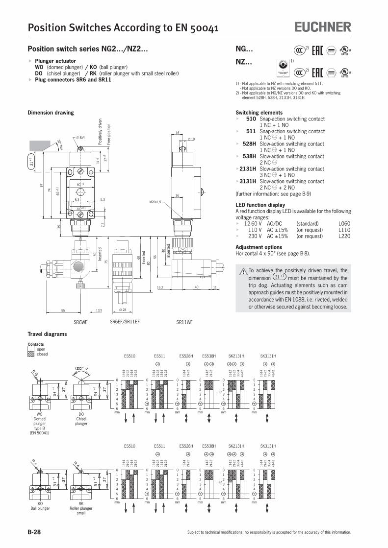
B-28
Position Switches According to EN 50041
Subject to technical modifications; no responsibility is accepted for the accuracy of this information.
01234
6
13-1
421
-22
13-1
421
-22
ES511
mm
13-1
421
-22
11-1
221
-22
ES528H ES538H
01234
6mm mm
6
43210
SK2131H
41-4
233
-34
21-2
211
-12
6
43210
41-4
233
-34
21-2
213
-14
SK3131H
mm
01234
6mm
2,5
01234
6
13-1
421
-22
13-1
421
-22
ES510
mm
5
01234
6
13-1
421
-22
13-1
421
-22
ES511
mm
13-1
421
-22
11-1
221
-22
ES528H ES538H
01234
6mm mm
6
43210
SK2131H
41-4
233
-34
21-2
211
-12
6
43210
41-4
233
-34
21-2
213
-14
SK3131H
mm
01234
6mm
2,5
01234
6
13-1
421
-22
13-1
421
-22
ES510
mm
5
Position switch series NG2…/NZ2…
Switching elements 510 Snap-action switching contact
1 NC + 1 NO 511 Snap-action switching contact
1 NC + 1 NO 528H Slow-action switching contact
1 NC + 1 NO 538H Slow-action switching contact
2 NC 2131H Slow-action switching contact
3 NC + 1 NO 3131H Slow-action switching contact
2 NC + 2 NO(further information: see page B-9)
LED function displayA red function display LED is available for the following voltage ranges:
12-60 V AC/DC (standard) L060110 V AC ±15% (on request) L110230 V AC ±15% (on request) L220
Adjustment optionsHorizontal 4 x 90° (see page B-8).
To achieve the positively driven travel, the dimension 31 +1 must be maintained by the trip dog. Actuating elements such as cam approach guides must be positively mounted in accordance with EN 1088, i.e. riveted, welded or otherwise secured against becoming loose.
30° max.
165,3
26
74
40 +1
30 ±0,1
5,3
7,3
60±
0,1
M20x1,5
31+
1
37±
1
16
∅ 10∅ 8x4
97
SR11WFSR6WF
55 13,5
50
75
40
56
40 1115,2
SR6EF/SR11EF
∅ 28
60
80
31+
1
Inse
rted
Inse
rted Inse
rted
Posi
tivel
y dr
iven
Free
pos
ition
WODomed plungertype B
(EN 50041)
DOChisel
plunger
KOBall plunger
RKRoller plunger
small
Plunger actuator WO (domed plunger) / KO (ball plunger) DO (chisel plunger) / RK (roller plunger with small steel roller)
Plug connectors SR6 and SR11
Dimension drawing
Travel diagrams
Contacts open
closed
NG… 2)
NZ…
1)
2)
1) - Not applicable to NZ with switching element 511. - Not applicable to NZ versions DO and KO.2) - Not applicable to NG/NZ versions DO and KO with switching
element 528H, 538H, 2131H, 3131H.

B-29
Position Switches According to EN 50041
Subject to technical modifications; no responsibility is accepted for the accuracy of this information.
B
Technical dataParameter Value UnitHousing material Anodized die-cast alloy
Degree of protection acc. to IEC 60529 IP 65
Installation position Any
Mechanical life 30 x 106 operating cycles
Ambient temperature - 25 … + 80 (-40 °C on request) °C
Weight Approx. 0.3 kg
Actuator Domed plunger (WO)
Chisel plunger (DO)
Ball plunger (KO)
Roller plunger, small (RK)
Approach speed, max. 1) 10 50 m/min
Approach speed, min. 0.1 m/min
Operating point accuracy 2) ± 0.002 0.01 °
Positively driven acc. to IEC 60947-5-1, appendix K See symbol in travel diagram
Actuating force, min. 15 N
Switching elements 510 528H 538H1 NC + 1 NO 1 NC + 1 NO 2 NC
511 2131H 3131H
1 + 1 NO 3 NC + 1 NO 2 NC + 2 NO
Switching principle Snap-action switching cont. Slow-action switching contact with H-contact bridge
Contact material Silver alloy, gold flashed
Contact closing time < 4 ms
Contact bounce time < 3 ms
Switching current, min., at 10 1 10 1 10 mA
switching voltage 24 24 12 24 12 V DC
Conventional thermal current Ith 6 4 A
Short circuit prot. acc. to IEC 60269-1 (control circuit fuse) 6 4 A gG
Connection Plug connector according to DIN 43651 3)
Rated impulse withstand voltage Uimp
kVWith plug connector SR6 2.5
With plug connector SR11 1.5
Rated insulation voltage Ui
VWith plug connector SR6 250
With plug connector SR11 50
Utilization category acc. to IEC 60947-5-1
With plug connector SR6 AC15 Ie 6 A Ue 230 V Ie 4 A Ue 230 V
DC13 Ie 6 A Ue 24 V Ie 4 A Ue 24 V
With plug connector SR11 AC15 Ie 4 A Ue 50 V
DC13 Ie 4 A Ue 24 V
1) The approach speed specified applies in conjunction with EUCHNER trip dogs according to DIN 69639.
2) The reproducible operating point accuracy refers to the plunger’s axial travel, after a run-in of approx. 2,000 operating cycles.
3) Wiring diagram: see page B-10.
Ordering table
Series Actuator Switching elementOrder no.
Function displaywithout L060
NG2...
WODomed plunger
510 090012 On request
NZ2…
511 090909 091280528 090910 091279538 090911 087558
2131 090912 -3131 090913 -
NG2...
DOChisel plunger
510 090011
On request
NZ2…
511 090015528 090914538 090915
2131 090916 -3131 090917 -
NG2...
RKRoller plunger, small
510 090918 091300
NZ2…
511 090016 099273528 090919 091292538 090920 On request2131 090921 -3131 090922 -
NG2... KOBall plunger 510 090020 On request

B-30
Position Switches According to EN 50041
Subject to technical modifications; no responsibility is accepted for the accuracy of this information.
01234
6
13-1
421
-22
13-1
421
-22
ES511
mm
13-1
421
-22
11-1
221
-22
ES528H ES538H
01234
6mm mm
6
432100
1234
6
13-1
421
-22
13-1
421
-22
ES510
mm
5
01234
6
13-1
421
-22
13-1
421
-22
ES511
mm
13-1
421
-22
11-1
221
-22
ES528H ES538H
01234
6mm mm
6
432100
1234
6
13-1
421
-22
13-1
421
-22
ES510
mm
5
Position switch series NG2…/NZ2…
Switching elements 510 Snap-action switching contact
1 NC + 1 NO 511 Snap-action switching contact
1 NC + 1 NO 528H Slow-action switching contact
1 NC + 1 NO 538H Slow-action switching contact
2 NC (further information: see page B-9)
LED function displayA red function display LED is available for the following voltage ranges:
12-60 V AC/DC (standard) L060110 V AC ±15% (on request) L110230 V AC ±15% (on request) L220
Adjustment optionsHorizontal 4 x 90° (see page B-8).
To achieve the positively driven travel, the dimension 31 +1 must be maintained by the trip dog. Actuating elements such as cam approach guides must be positively mounted in accordance with EN 1088, i.e. riveted, welded or otherwise secured against becoming loose.
16
42
32
74
40 +1
30 ±0,1
5,3
7,3
60±
0,1
22
45°
26,5
31
31+
1
37±
1
∅ 10
16
97
5,3 M20x1,5
∅ 8x4
30° max.
31+
1
Guide lug aligned
Right-angle plug connector:male socket adjustable max. 270°.Default setting: cable outlet to the right.
Posi
tivel
y dr
iven
Free
pos
ition
WODomed plungertype B
(EN 50041)
DOChisel
plunger
KOBall plunger
RKRoller plunger
small
Plunger actuator WO (domed plunger) / KO (ball plunger) DO (chisel plunger) / RK (roller plunger with small steel roller)
Plug connector M12/SVM5
Dimension drawing
Travel diagrams
Contacts open
closed
NG… 2)
NZ…
1)
2)
1) - Not applicable to NZ with switching element 511. - Not applicable to NZ versions DO and KO.2) - Not applicable to NG/NZ versions DO and KO with switching
element 528H, 538H, 2131H, 3131H.

B-31
Position Switches According to EN 50041
Subject to technical modifications; no responsibility is accepted for the accuracy of this information.
B
Technical dataParameter Value UnitHousing material Anodized die-cast alloy
Degree of protection acc. to IEC 60529 IP 67
Installation position Any
Mechanical life 30 x 106 operating cycles
Ambient temperature - 25 … + 80 (-40 °C on request) °C
Weight Approx. 0.3 kg
Actuator Domed plunger (WO)
Chisel plunger (DO)
Ball plunger (KO)
Roller plunger, small (RK)
Approach speed, max. 1) 10 50 m/min
Approach speed, min. 0.1 m/min
Operating point accuracy 2) ± 0.002 0.01 mm
Positively driven acc. to IEC 60947-5-1, appendix K See symbol in travel diagram
Actuating force, min. 15 N
Switching elements 510 528H 538H1 NC + 1 NO 1 NC + 1 NO 2 NC
511
1 + 1 NO
Switching principle Snap-action switching contact
Slow-action switching contact with H-contact bridge
Contact material Silver alloy, gold flashed
Contact closing time < 4 ms
Contact bounce time < 3 ms
Rated impulse withstand voltage Uimp 1.5 kV
Rated insulation voltage Ui 50 V
Utilization category acc. to IEC 60947-5-1
Plug connector SVM5 AC15 Ie 4 A Ue 30 V Ie 4 A Ue 30 V
DC13 Ie 4 A Ue 24 V Ie 4 A Ue 24 V
Switching current, min., at 10 1 10 1 10 mA
switching voltage 24 24 12 24 12 V DC
Conventional thermal current Ith 4 4 A
Short circuit prot. acc. to IEC 60269-1 (control circuit fuse) 4 4 A gG
Connection Plug connector M12 3)
1) The approach speed specified applies in conjunction with EUCHNER trip dogs according to DIN 69639.
2) The reproducible operating point accuracy refers to the plunger’s axial travel, after a run-in of approx. 2,000 operating cycles.
3) Wiring diagram: see page B-10.
Ordering table
Series Actuator Switching elementOrder no.
Plug connectorSVM5
NG2...WO
Domed plunger
510 090018
NZ2…511 089014528 090923538 090924
NG2...DO
Chisel plunger
510 090014
NZ2…511 090927528 090928538 090929
NG2...RK
Roller plunger, small
510 089020
NZ2…511 089007528 090930538 089018
NG2... KOBall plunger 510 090931
Ordering example: Position switch without safety function NG, plug connector 2,small roller plunger RK, snap-action switching element 510,M12 male socket with PE connection SVM5NG2RK-510SVM5 Order no. 089020

B-32
Position Switches According to EN 50041
Subject to technical modifications; no responsibility is accepted for the accuracy of this information.
Position switch series NG1…/NZ1…
Switching elements 510 Snap-action switching contact
1 NC + 1 NO 511 Snap-action switching contact
1 NC + 1 NO 528H Slow-action switching contact
1 NC + 1 NO 538H Slow-action switching contact
2 NC 2131H Slow-action switching contact
3 NC + 1 NO 3131H Slow-action switching contact
2 NC + 2 NO(further information: see page B-9)
LED function displayA red function display LED is available for the following voltage ranges:
12-60 V AC/DC (standard) L060110 V AC ±15% (on request) L110230 V AC ±15% (on request) L220
Adjustment optionsHorizontal 4 x 90° (see page B-8).
If damaged or worn, safety switches must be replaced as a unit.
Notes on installation for position switches with safety switching elements
To achieve the positively driven travel, the dimension 44 +1 must be maintained by the trip dog. Actuating elements such as cam approach guides must be positively mounted in accordance with EN 1088, i.e. riveted, welded or otherwise secured against becoming loose.
M20x1,5
30° max.
44+
1
Free
pos
ition
Posi
tivel
y dr
iven
RGPlastic roller
RSSteel roller
RLExtended
roller plunger
01234
6
13-1
421
-22
13-1
421
-22
ES511
mm
13-1
421
-22
11-1
221
-22
ES528H ES538H
01234
6mm mm
6
43210
SK2131H
41-4
233
-34
21-2
211
-12
6
43210
41-4
233
-34
21-2
213
-14
SK3131H
mm
01234
6mm
2,5
01234
6
13-1
421
-22
13-1
421
-22
ES510
mm
5
Plunger actuator RG (roller plunger, plastic roller) RS (roller plunger, steel roller) RL (extended roller plunger)
Cable entry M20 x 1.5
Dimension drawing
Travel diagrams
Contacts open
closed
NG… NZ…
1)
1) Not applicable to NZ with switching element 511.

B-33
Position Switches According to EN 50041
Subject to technical modifications; no responsibility is accepted for the accuracy of this information.
B
Technical dataParameter Value UnitHousing material Anodized die-cast alloy
Degree of protection acc. to IEC 60529 IP 67
Installation position Any
Mechanical life 30 x 106 operating cycles
Ambient temperature - 25 … + 80 (-40 °C on request) °C
Weight Approx. 0.3 kg
Actuator Roller plunger, plastic roller (RG)
Roller plunger, steel roller (RS)
Extended roller plunger (RL)
Approach speed, max. 1) 20 m/min
Approach speed, min. 0.1 m/min
Operating point accuracy 2) ± 0.1 mm
Positively driven acc. to IEC 60947-5-1, appendix K See symbol in travel diagram
Actuating force, min. 15 N
Switching elements 510 528H 538H1 NC + 1 NO 1 NC + 1 NO 2 NC
511 2131H 3131H
1 + 1 NO 3 NC + 1 NO 2 NC + 2 NO
Switching principle Snap-action switching contact
Slow-action switching contact with H-contact bridge
Contact material Silver alloy, gold flashed
Contact closing time < 4 ms
Contact bounce time < 3 ms
Rated impulse withstand voltage Uimp 2.5 kV
Rated insulation voltage Ui 250 V
Utilization category acc. to IEC 60947-5-1
AC12 Ie 10 A Ue 230 V -
AC15 Ie 6 A Ue 230 V Ie 4 A Ue 230 V
DC13 Ie 6 A Ue 24 V Ie 4 A Ue 24 V
Switching current, min., at 10 1 10 1 10 mA
switching voltage 24 24 12 24 12 V DC
Conventional thermal current Ith 6 4 A
Short circuit prot. acc. to IEC 60269-1 (control circuit fuse) 10/6 4 A gG
Connection Screw terminal 3)
Conductor cross-section, max. 2 x 1.5 mm²
1) The approach speed specified applies in conjunction with EUCHNER trip dogs according to DIN 69639.
2) The reproducible operating point accuracy refers to the plunger's axial travel, after a run-in of approx. 2,000 operating cycles.
3) Wiring diagram: see page B-9.
Ordering table
Series Actuator Switching elementOrder no.
Function displaywithout L060
NG1…-M
RGRoller plungerPlastic roller
510 079941 090398
NZ1…-M
511 088605 089052528 090932 090008538 090933 090009
2131 090934 -3131 090935 -
NG1…-M
RSRoller plunger
Steel roller
510 079942 079943
NZ1…-M
511 079960 089053528 089627 086413538 090936 090555
2131 089633 -3131 089631 -
NG1…-M
RLExtended roller plunger
510 086324 090602
NZ1…-M
511 088614 088996528 090937 090938538 090939 090940
2131 090941 -3131 090942 -
Ordering example: Position switch with safety function NZ, cable entry 1,roller plunger with plastic roller RG, snap-action switching element 511,function display L060 10 - 60 V, metric thread M20 x 1.5 MNZ1RG-511L060-M Order no. 089052

B-34
Position Switches According to EN 50041
Subject to technical modifications; no responsibility is accepted for the accuracy of this information.
Position switch series NG2…/NZ2…
Switching elements 510 Snap-action switching contact
1 NC + 1 NO 511 Snap-action switching contact
1 NC + 1 NO 528H Slow-action switching contact
1 NC + 1 NO 538H Slow-action switching contact
2 NC 2131H Slow-action switching contact
3 NC + 1 NO 3131H Slow-action switching contact
2 NC + 2 NO(further information: see page B-9)
LED function displayA red function display LED is available for the following voltage ranges:
12-60 V AC/DC (standard) L060110 V AC ±15% (on request) L110230 V AC ±15% (on request) L220
Adjustment optionsHorizontal 4 x 90° (see page B-8).
If damaged or worn, safety switches must be replaced as a unit.
Notes on installation for position switches with safety switching elements
To achieve the positively driven travel, the dimension 44 +1 must be maintained by the trip dog. Actuating elements such as cam approach guides must be positively mounted in accordance with EN 1088, i.e. riveted, welded or otherwise secured against becoming loose.
4232
16
16
ø10
4
SR11WFSR6WF
55 13,5
50
75
40
56
40 1115,2
SR6EF/SR11EF
∅ 28
60
80
74 60±
0,1
26
40 +1
30 ±0,1
5,3
7,3
R6
97
5,3
50±
1
30° max.
44+
1
44+
1
Posi
tivel
y dr
iven
Free
pos
ition
RGPlastic roller
RSSteel roller
RLExtended
roller plunger
01234
6
13-1
421
-22
13-1
421
-22
ES511
mm
13-1
421
-22
11-1
221
-22
ES528H ES538H
01234
6mm mm
6
43210
SK2131H
41-4
233
-34
21-2
211
-12
6
43210
41-4
233
-34
21-2
213
-14
SK3131H
mm
01234
6mm
2,5
01234
6
13-1
421
-22
13-1
421
-22
ES510
mm
5
Plunger actuator RG (roller plunger, plastic roller) RS (roller plunger, steel roller) RL (extended roller plunger)
Plug connectors SR6 and SR11
Dimension drawingIn
sert
ed
Inse
rted Inse
rted
Travel diagrams
Contacts open
closed
NG… NZ…
1)
1) Not applicable to NZ with switching element 511.

B-35
Position Switches According to EN 50041
Subject to technical modifications; no responsibility is accepted for the accuracy of this information.
B
Technical dataParameter Value UnitHousing material Anodized die-cast alloy
Degree of protection acc. to IEC 60529 IP 65
Installation position Any
Mechanical life 30 x 106 operating cycles
Ambient temperature - 25 … + 80 (-40 °C on request) °C
Weight Approx. 0.3 kg
Actuator Roller plunger, plastic roller (RG)
Roller plunger, steel roller (RS)
Extended roller plunger (RL)
Approach speed, max. 1) 20 m/min
Approach speed, min. 0.1 m/min
Operating point accuracy 2) ± 0.1 mm
Positively driven acc. to IEC 60947-5-1, appendix K See symbol in travel diagram
Actuating force, min. 15 N
Switching elements 510 528H 538H1 NC + 1 NO 1 NC + 1 NO 2 NC
511 2131H 3131H
1 + 1 NO 3 NC + 1 NO 2 NC + 2 NO
Switching principle Snap-action switching cont. Slow-action switching contact with H-contact bridge
Contact material Silver alloy, gold flashed
Contact closing time < 4 ms
Contact bounce time < 3 ms
Switching current, min., at 10 1 10 1 10 mA
switching voltage 24 24 12 24 12 V DC
Conventional thermal current Ith 6 4 A
Short circuit prot. acc. to IEC 60269-1 (control circuit fuse) 6 4 A gG
Connection Plug connector according to DIN 43651 3)
Rated impulse withstand voltage Uimp
kVWith plug connector SR6 2.5
With plug connector SR11 1.5
Rated insulation voltage Ui
VWith plug connector SR6 250
With plug connector SR11 50
Utilization category acc. to IEC 60947-5-1
With plug connector SR6 AC15 Ie 6 A Ue 230 V Ie 4 A Ue 230 V
DC13 Ie 6 A Ue 24 V Ie 4 A Ue 24 V
With plug connector SR11 AC15 Ie 4 A Ue 50 V Ie 4 A Ue 50 V
DC13 Ie 4 A Ue 24 V Ie 4 A Ue 24 V
1) The approach speed specified applies in conjunction with EUCHNER trip dogs according to DIN 69639.
2) The reproducible operating point accuracy refers to the plunger's axial travel, after a run-in of approx. 2,000 operating cycles.
3) Wiring diagram: see page B-10.
Ordering table
Series Actuator Switching elementOrder no.
Function displaywithout L060
NG2...
RGRoller plungerPlastic roller
510 090021 090949
NZ2…
511 090032 091284528 090943 090944538 090945 090946
2131 090947 -3131 090948 -
NG2...
RSRoller plunger
Steel roller
510 090953 On request
NZ2…
511 090024 090147528 090950 088197538 090951 090952
2131 090149 -3131 090954 -
NG2...
RLExtended roller plunger
510 090022 091285
NZ2…
511 090025 090955528 090956 091282538 090957 091278
2131 090958 -3131 090959 -

B-36
Position Switches According to EN 50041
Subject to technical modifications; no responsibility is accepted for the accuracy of this information.
Position switch series NG2…/NZ2…
Switching elements 510 Snap-action switching contact
1 NC + 1 NO 511 Snap-action switching contact
1 NC + 1 NO 528H Slow-action switching contact
1 NC + 1 NO 538H Slow-action switching contact
2 NC (further information: see page B-9)
LED function displayAvailable on request
Adjustment optionsHorizontal 4 x 90° (see page B-8).
If damaged or worn, safety switches must be replaced as a unit.
Notes on installation for position switches with safety switching elements
To achieve the positively driven travel, the dimension 44 +1 must be maintained by the trip dog. Actuating elements such as cam approach guides must be positively mounted in accordance with EN 1088, i.e. riveted, welded or otherwise secured against becoming loose.
16
42
32
74
40 +1
30 ±0,1
5,3
7,3
60±
0,1
22
45°
26,5
31
R6
50±
1
16
∅ 10
4
97
44+
1
30° max.
44+
1
Guide lug aligned
Right-angle plug connector:cable outlet adjustable to a max. of 270°.Default setting: cable outlet to the right.
Posi
tivel
y dr
iven
Free
pos
ition
RGPlastic roller
RSSteel roller
RLExtended
roller plunger
01234
6
13-1
421
-22
13-1
421
-22
ES511
mm
13-1
421
-22
11-1
221
-22
ES528H ES538H
01234
6mm mm
6
432100
1234
6
13-1
421
-22
13-1
421
-22
ES510
mm
5
Plunger actuator RG (roller plunger, plastic roller) RS (roller plunger, steel roller) RL (extended roller plunger)
Plug connector M12/SVM5
Dimension drawing
Travel diagrams
Contacts open
closed
NG… NZ…
1)
1) Not applicable to NZ with switching element 511.

B-37
Position Switches According to EN 50041
Subject to technical modifications; no responsibility is accepted for the accuracy of this information.
B
Technical dataParameter Value UnitHousing material Anodized die-cast alloy
Degree of protection acc. to IEC 60529 IP 67
Installation position Any
Mechanical life 30 x 106 operating cycles
Ambient temperature - 25 … + 80 (-40 °C on request) °C
Weight Approx. 0.3 kg
Actuator Roller plunger, plastic roller (RG)
Roller plunger, steel roller (RS)
Extended roller plunger (RL)
Approach speed, max. 1) 20 m/min
Approach speed, min. 0.1 m/min
Operating point accuracy 2) ± 0.1 mm
Positively driven acc. to IEC 60947-5-1, appendix K See symbol in travel diagram
Actuating force, min. 15 N
Switching elements 510 528H 538H1 NC + 1 NO 1 NC + 1 NO 2 NC
511
1 + 1 NO
Switching principle Snap-action switching contact
Slow-action switching contact with H-contact bridge
Contact material Silver alloy, gold flashed
Contact closing time < 4 ms
Contact bounce time < 3 ms
Rated impulse withstand voltage Uimp 1.5 kV
Rated insulation voltage Ui 50 V
Utilization category acc. to IEC 60947-5-1
Plug connector SVM5 AC15 Ie 4 A Ue 30 V Ie 4 A Ue 30 V
DC13 Ie 4 A Ue 24 V Ie 4 A Ue 24 V
Switching current, min., at 10 1 10 1 10 mA
switching voltage 24 24 12 24 12 V DC
Conventional thermal current Ith 4 4 A
Short circuit prot. acc. to IEC 60269-1 (control circuit fuse) 4 4 A gG
Connection Plug connector M12 3)
1) The approach speed specified applies in conjunction with EUCHNER trip dogs according to DIN 69639.
2) The reproducible operating point accuracy refers to the plunger's axial travel, after a run-in of approx. 2,000 operating cycles.
3) Wiring diagram: see page B-10.
Ordering table
Series Actuator Switching elementOrder no.
Plug connectorSVM5
NG2...RG
Roller plungerPlastic roller
510 090960
NZ2…511 090026528 090961538 090962
NG2...RS
Roller plungerSteel roller
510 088632
NZ2…511 090027528 090963538 090964
NG2...RL
Extended roller plunger
510 On request
NZ2…511 090028528
On request538
Ordering example: Position switch with safety function NZ, plug connector 2,roller plunger with plastic roller RG, snap-action switching element 511,M12 male socket with PE connection SVM5NZ2RG-511SVM5 Order no. 090026

B-38
Position Switches According to EN 50041
Subject to technical modifications; no responsibility is accepted for the accuracy of this information.
Position switch series NG1…
Switching elements 510 Snap-action switching contact
1 NC + 1 NO(further information: see page B-9)
LED function displayA red function display LED is available for the following voltage ranges:
12-60 V AC/DC (standard) L060110 V AC ±15% (on request) L110230 V AC ±15% (on request) L220
74
5,3
60±
0,1
40 +1
30 ±0,1
16
32
42
M20x1,5
7,3
∅ 820° 20°13
0
16
5,3
Operating point
Spring actuator FO Cable entry M20 x 1.5 Actuating direction: all sides
Dimension drawing

B-39
Position Switches According to EN 50041
Subject to technical modifications; no responsibility is accepted for the accuracy of this information.
B
Technical dataParameter Value UnitHousing material Anodized die-cast alloy
Degree of protection acc. to IEC 60529 IP 67
Installation position Any
Mechanical life 30 x 106 operating cycles
Ambient temperature - 25 … + 80 (-40 °C on request) °C
Weight Approx. 0.35 kg
Actuator Spring actuator made of spring steel wire (FO)
Approach speed, max. 20 m/min
Approach speed, min. 0.5 m/min
Actuating force, min. 5 N
Switching elements 5101 NC + 1 NO
Switching principle Snap-action switching contact
Contact material Silver alloy, gold flashed
Contact closing time < 4 ms
Contact bounce time < 3 ms
Rated impulse withstand voltage Uimp 2.5 kV
Rated insulation voltage Ui 250 V
Utilization category acc. to IEC 60947-5-1
AC12 Ie 10 A Ue 230 V
AC15 Ie 6 A Ue 230 V
DC13 Ie 6 A Ue 24 V
Switching current, min., at 10 mA
switching voltage 24 V DC
Conventional thermal current Ith 6 A
Short circuit prot. acc. to IEC 60269-1 (control circuit fuse) 10/6 A gG
Connection Screw terminal 1)
Conductor cross-section, max. 2 x 1.5 mm²
1) Wiring diagram: see page B-9.
Ordering table
Series Actuator Switching elementOrder no.
Function displaywithout L060
NG1…-M FOSpring actuator 510 079911 090029
Ordering example: Position switch without safety function NG, cable entry 1,spring steel wire spring actuator FO, snap-action switching element 510,function display L060 10 - 60 V, metric thread M20 x 1.5 MNG1FO-510L060-M Order no. 090 029

B-40
Position Switches According to EN 50041
Subject to technical modifications; no responsibility is accepted for the accuracy of this information.
Position switch series NG2…
Switching elements 510 Snap-action switching contact
1 NC + 1 NO(further information: see page B-9)
LED function displayAvailable on request
8
26,5
31
40 0+1
74
5,3
22
5,3
7,3
30 ±0,1
60±
0,1
130
20°20°
16
16
M20x1,5
32
42
45°
Operating point
Guide lug aligned
Right-angle plug connector:cable outlet adjustable to max. 270°.Default setting: cable outlet to the right.
Spring actuator FO Plug connector M12/SVM5 Actuating direction: all sides
Dimension drawing

B-41
Position Switches According to EN 50041
Subject to technical modifications; no responsibility is accepted for the accuracy of this information.
B
Technical dataParameter Value UnitHousing material Anodized die-cast alloy
Degree of protection acc. to IEC 60529 IP 67
Installation position Any
Mechanical life 30 x 106 operating cycles
Ambient temperature - 25 … + 80 (-40 °C on request) °C
Weight Approx. 0.35 kg
Actuator Spring actuator made of spring steel wire (FO)
Approach speed, max. 20 m/min
Approach speed, min. 0.5 m/min
Actuating force, min. 5 N
Switching elements 5101 NC + 1 NO
Switching principle Snap-action switching contact
Contact material Silver alloy, gold flashed
Contact closing time < 4 ms
Contact bounce time < 3 ms
Rated impulse withstand voltage Uimp 1.5 kV
Rated insulation voltage Ui 50 V
Utilization category acc. to IEC 60947-5-1
Plug connector SVM5 AC15 Ie 4 A Ue 30 V
DC13 Ie 4 A Ue 24 V
Switching current, min., at 10 mA
switching voltage 24 V DC
Conventional thermal current Ith 4 A
Short circuit prot. acc. to IEC 60269-1 (control circuit fuse) 4 A gG
Connection Plug connector M12 1)
1) Wiring diagram: see page B-10.
Ordering table
Series Actuator Switching elementOrder no.
Plug connectorSVM5
NG2... FOSpring actuator 510 092058
Ordering example: Position switch without safety function NG, plug connector 2,spring steel wire spring actuator FO, snap-action switching element 510,M12 male socket with PE connection SVM5 NG2FO-510SVM5 Order no. 092 058

B-42
Position Switches According to EN 50041
Subject to technical modifications; no responsibility is accepted for the accuracy of this information.
Special versions (other special versions available on request)
Position switch with plug connector according to DIN 43651VW/Audi, VW mat. no. 2348
Item Order no.NZ2HB-511L060C1630 054121
Plug connector according to DIN 43651Type SR6AM2
21-2213-14
13-1421-22
0°22°
10°
45°
75°
45° +5°
60±
0,1
225,3
7,3
22
5,3
100
74
21
1413
1 3 4 2 6
30±0,1
40+1
26
Position switch with plug connector and elbow adapter according to DIN 43651VW/Audi, VW mat. no. 2349
Item Order no.NZ2HB-511L060C1631 054122
22
∅18
32
56
64
16
21
1413
1 3 4 2 6
45
6
40
24
Plug connector according to DIN 43651Type SR6AM2
Position switch with large plastic rollerDiameter 30 mm
Item Order no.NZ1HB-511-MC569 079965
Position switch with sealed bearingsDiameter 19 mm
Item Order no.NZ1HS-511-MC1833 091312
74
100
5,3
5,3
22
60±
0,1
40 +1
30 ±0,1
7,3
75°
22°10°0°
45°21-2213-1421-2213-14
13
21
14
22
45° +5°
DA
B
C
22
14
21
13
13-1421-2213-1421-22
45°
0° 10°22°
75°
60±0,
1
7,3
5,35,3
22
100
74
30 ±0,1
40 +1
+5°45°
Switching elementES511 snap-action contact element
1 NO + 1 NC Positively driven contact
Switching elementES511 snap-action contact element
1 NO + 1 NC Positively driven contact
Position switch with steel roller on the inside of the lever
Item Order no.NZ1HS-3131-MC1779 079996
Switching elementSK3131 slow-action contact element
2 NO + 2 NC Positively driven contact
16
32
42
M20x1,5
41 42
33 34
2221
13 14
32
∅18
6
38
52
Position switch with M12 plug connector and pin assignment for LED indicator(pin 3 not used)
Item Order no.NG2HB-510SVM5C1883 086561
74
100
5,3
7,3
5,3
22
60±
0,1
22
40 +1
30 ±0,1
75°
22°0° 10°
13-1421-2213-1421-22
CA
B
5 GN/YE
PIN 3 BK
WHBN 1
2
4
2221
13 14
Not used

B-43
Position Switches According to EN 50041
Subject to technical modifications; no responsibility is accepted for the accuracy of this information.
B
Position switch with protective NBR bellows on the plunger guideProtection against serious contamination and aggressive coolants
Item Order no.NZ1RS-511-MC1588 091352
Position switch with gold plated contactsFor switching low currents of at least 1 mA
Item Order no.NZ1RS-510AU-M 090416
74
5,3
60±
0,1
40 +1
30 ±0,1
7,3
48±
1 50±
1
5,3
13
21
14
22
44+
1
Switching elementES511 snap-action contact element
1 NO + 1 NC Positively driven contact
48±
1 50±
1
R6
97
5,3
30 ±0,1
40 +1
5,3
74
60±
0,1
7,3
M=0,6Nm
Switching element ES510 snap-action contact element1 NO + 1 NCContact material: silver alloy 10 μm electro-gold-platedannular cutting edge contactBreaking capacity max. 30 V / 100 mAMin. breaking capacity 5 V / 1 mA
Position switch with sealed bearingsDiameter 16 mm
Item Order no.NZ1RL-3131-MC1831 089082
Position switch with MENCOM plug connector MIN-9MR-1-18
Item Order no.NZ1RS-2131-9C-GMMF 077362
5,3
30 ±0,1
40 +1
5,3
97
74
60±
0,1
7,3
41 42
33 34
2221
13 14
50-1
52±
1
53±
1
55±
1
Switching elementSK3131 slow-action contact element
2 NO + 2 NC Positively driven contact
5,3 5,3
7,3
32
R6
+1
44
50±
1
48±
1
1
97
74
60±
0,1
47,5
±1
40 +1
30 ±0,1
1211
21 22
3433
4241
2
3
1
69
5
8
4
7
1
2
3 4
5
6
78 9
Position switch with two LED indicatorsDiameter 18 mm
Item Order no.NZ1HB-528L024GEGR-M Plastic roller 099929NZ1HS-528L024GEGR-M Steel roller 099930
40 0+1
30 ±0,1
5,3
7,3
60±
0,1
74
5,3
100
22
45° 0°+5°
45°
0°22°
40°
75°
13 - 1421 - 22
A/D
E B
C
0 V
RD
BN
13
21
14
22
LED YE
LED GN
Switching elementES528 slow-action contact element
1 NO + 1 NC Positively driven contactOperating voltage for LED indicator24 V DC, +10%, -15%
LEDyellowLEDgreen
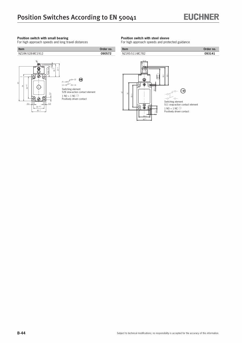
B-44
Position Switches According to EN 50041
Subject to technical modifications; no responsibility is accepted for the accuracy of this information.
Position switch with small bearingFor high approach speeds and long travel distances
Item Order no.NZ1RK-528-MC1912 090572
74
5,3
60±
0,1
40 +1
30 ±0,1
7,3
5,3
13
21
14
22
R4
1,5
31+
1
35±
1
37±
1
97
Switching element528 slow-action contact element
1 NO + 1 NC Positively driven contact
Position switch with steel sleeveFor high approach speeds and protected guidance
Item Order no.NZ1RS-511-MC782 093141
60±
0,1
30 ±0,1
5048±
1
4401
97
74
Ø5,
37,
3
5,3
40 01
R6
Ø 18
±1
+
+
Switching element511 snap-action contact element
1 NO + 1 NC Positively driven contact

B-45
Position Switches According to EN 50041
Subject to technical modifications; no responsibility is accepted for the accuracy of this information.
B
Accessories
Notice:The actuator heads and actuators (except for roller lever NHB, NHS, NHSC...) are replacement parts for position switches without safety function. They do not fit position switches with safety function and must not be operated with these switches.
Rod lever
Item Order no.NSB (plastic rod) 012052NSM (aluminum rod) 012053
Lever arm actuation
Item Order no.NSA 012051
Roller arm
Item Order no.NHB (plastic roller) 012042NHS (steel roller) 012043NHSC1834 (ball bearing 19 mm) 077349
25
M3
Spring actuator
Item Order no.NFO (spring steel wire) 011909
Adjustable roller arm
Item Order no.NVB (plastic roller) 012064NVS (steel roller) 012065
25
M3

B-46
Position Switches According to EN 50041
Subject to technical modifications; no responsibility is accepted for the accuracy of this information.
Notice:The actuator heads shown are spare parts for position switches without safety function.They do not fit position switches with safety function and must not be operated with these switches.
Actuator with small roller plunger
Item Order no.NRK (small steel roller) 012049
Actuator with ball plunger
Item Order no.NKO (steel ball) 012045
25
M3
25
M3
Actuator with extended roller plunger 18 mm
Item Order no.NRL (large steel roller) 012050
Actuator with chisel plunger
Item Order no.NDO (polish-ground chisel plunger) 011908
25
M3
25
M3
Actuator with roller plunger 12 mm
Item Order no.NRG (plastic roller) 012046NRS (steel roller) 012047
Actuator with domed plunger
Item Order no.NWO (polish-ground dome) 012066
25
M3
25
M3
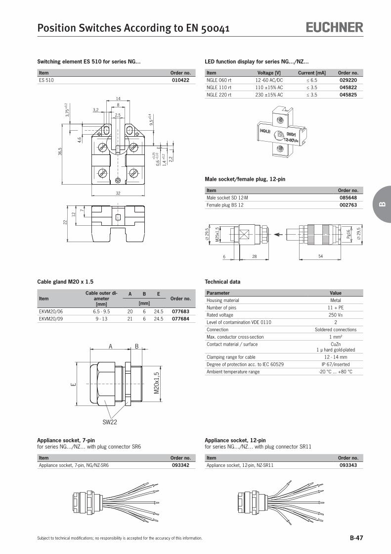
B-47
Position Switches According to EN 50041
Subject to technical modifications; no responsibility is accepted for the accuracy of this information.
B
Cable gland M20 x 1.5
ItemCable outer di-
ameter[mm]
A B EOrder no.
[mm]
EKVM20/06 6.5 - 9.5 20 6 24.5 077683EKVM20/09 9 - 13 21 6 24.5 077684
E
M20
x1,5
BA
SW22
Technical data
Parameter ValueHousing material Metal
Number of pins 11 + PE
Rated voltage 250 V
Level of contamination VDE 0110 2
Connection Soldered connections
Max. conductor cross-section 1 mm²
Contact material / surface CuZn1 μ hard gold-plated
Clamping range for cable 12 - 14 mm
Degree of protection acc. to IEC 60529 IP 67/inserted
Ambient temperature range -20 °C ... +80 °C
Appliance socket, 7-pinfor series NG…/NZ… with plug connector SR6
Item Order no.Appliance socket, 7-pin, NG/NZ-SR6 093342
Appliance socket, 12-pinfor series NG…/NZ… with plug connector SR11
Item Order no.Appliance socket, 12-pin, NZ-SR11 093343
Male socket/female plug, 12-pin
Item Order no.Male socket SD 12-M 085648Female plug BS 12 002763
∅29
,5
M25
x1,5
6 28 54
Pg16
∅29
,5
Switching element ES 510 for series NG…
Item Order no.ES 510 010422
7
22
12
32
36,5
4,6
3,75
±0,
2
2,53,2
8
14
9,5
1,4
0,6 2,
2+0,
2 5–0
,10
±0,
2
±0,
4
LED function display for series NG…/NZ…
Item Voltage [V] Current [mA] Order no.NGLE 060 rt 12 -60 AC/DC 6.5 029220NGLE 110 rt 110 ±15% AC 3.5 045822NGLE 220 rt 230 ±15% AC 3.5 045825

B-48
Position Switches According to EN 50041
Subject to technical modifications; no responsibility is accepted for the accuracy of this information.
Plug connector SR6 (socket 6+PE) with/without connecting cable
Plug connector SR11 (socket 11+PE) with/without connecting cable
View on connection side of the 12-pin female connector
SR11EF… SR11WF…
Inserted Inserted
View on connection side of the 7-pin female connector
SR6EF… SR6WF…
Inserted Inserted
Socket pin Wire num-ber
1 1
2 2
3 3
4 4
5 5
6 6� 7
Socket pin Wire num-ber
1 1
2 2
3 3
4 4
5 5
6 6
7 7
8 8
9 9
10 10
11 11� 12
Technical data
Parameter ValueHousing material Plastic
Number of pins 6 + PE
Rated voltage 250 V
Degree of protection acc. to IEC 60529 IP 65/inserted
Connecting cable PUR gray
Outer diameter 8 mm
Conductor cross-section 1.0 mm²
Technical data
Parameter ValueHousing material Plastic
Number of pins 11 + PE
Rated voltage 50 V
Degree of protection acc. to IEC 60 529 IP 65/inserted
Connecting cable PUR gray
Outer diameter 10.5 mm
Conductor cross-section 1.0 mm²
Ordering table
Plug version Connecting cable Item Order no.
SocketStraight
without SR6EF 0131765 m SR6EF-5000 077632
10 m SR6EF-10000 07763315 m SR6EF-15000 077634
SocketAngled
without SR6WF 0249995 m SR6WF-5000 077638
10 m SR6WF-10000 07763915 m SR6WF-15000 077640
Ordering table
Plug version Connecting cable Item Order no.
Straight socket
without SR11EF 0708595 m SR11EF-5000 077629
10 m SR11EF-10000 07763015 m SR11EF-15000 077631
Angled socket
without SR11WF 0547735 m SR11WF-5000 077635
10 m SR11WF-10000 07763615 m SR11WF-15000 077637

B-49
For Your Notes
Subject to technical modifications; no responsibility is accepted for the accuracy of this information.
B

B-50

C-1
C
Multiple Limit Switches, Trip Rails and Trip Dogs
C

C-2

Contents
C-3
C
General C-4
Multiple limit switches C-8
Accessories C-23
Technical data C-26
Trip rails/trip dogs C-29
Appendix
Glossary C-33
Multiple limit switches, trip rails and trip dogs
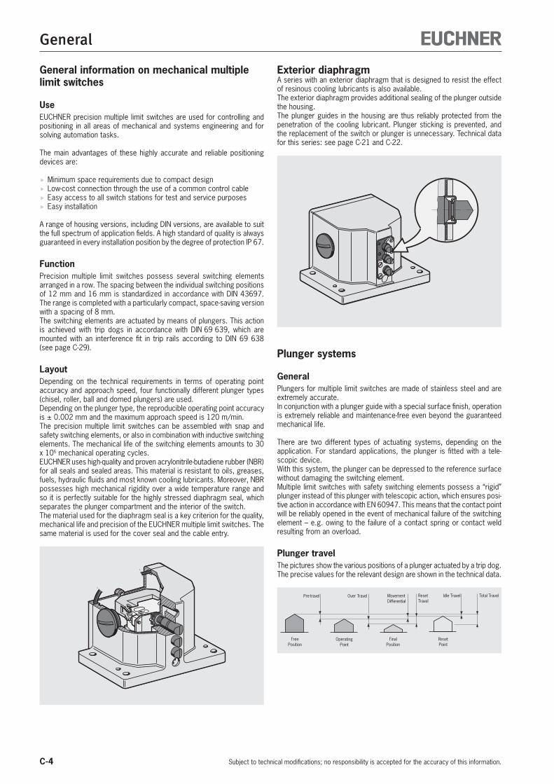
C-4
General
Subject to technical modifications; no responsibility is accepted for the accuracy of this information.
General information on mechanical multiple limit switches
UseEUCHNER precision multiple limit switches are used for controlling and positioning in all areas of mechanical and systems engineering and for solving automation tasks.
The main advantages of these highly accurate and reliable positioning devices are:
Minimum space requirements due to compact design Low-cost connection through the use of a common control cable Easy access to all switch stations for test and service purposes Easy installation
A range of housing versions, including DIN versions, are available to suit the full spectrum of application fields. A high standard of quality is always guaranteed in every installation position by the degree of protection IP 67.
FunctionPrecision multiple limit switches possess several switching elements arranged in a row. The spacing between the individual switching positions of 12 mm and 16 mm is standardized in accordance with DIN 43697. The range is completed with a particularly compact, space-saving version with a spacing of 8 mm.The switching elements are actuated by means of plungers. This action is achieved with trip dogs in accordance with DIN 69 639, which are mounted with an interference fit in trip rails according to DIN 69 638 (see page C-29).
LayoutDepending on the technical requirements in terms of operating point accuracy and approach speed, four functionally different plunger types (chisel, roller, ball and domed plungers) are used. Depending on the plunger type, the reproducible operating point accuracy is ± 0.002 mm and the maximum approach speed is 120 m/min.The precision multiple limit switches can be assembled with snap and safety switching elements, or also in combination with inductive switching elements. The mechanical life of the switching elements amounts to 30 x 106 mechanical operating cycles.EUCHNER uses high-quality and proven acrylonitrile-butadiene rubber (NBR) for all seals and sealed areas. This material is resistant to oils, greases, fuels, hydraulic fluids and most known cooling lubricants. Moreover, NBR possesses high mechanical rigidity over a wide temperature range and so it is perfectly suitable for the highly stressed diaphragm seal, which separates the plunger compartment and the interior of the switch. The material used for the diaphragm seal is a key criterion for the quality, mechanical life and precision of the EUCHNER multiple limit switches. The same material is used for the cover seal and the cable entry.
Exterior diaphragmA series with an exterior diaphragm that is designed to resist the effect of resinous cooling lubricants is also available. The exterior diaphragm provides additional sealing of the plunger outside the housing. The plunger guides in the housing are thus reliably protected from the penetration of the cooling lubricant. Plunger sticking is prevented, and the replacement of the switch or plunger is unnecessary. Technical data for this series: see page C-21 and C-22.
Plunger systems
GeneralPlungers for multiple limit switches are made of stainless steel and are extremely accurate. In conjunction with a plunger guide with a special surface finish, operation is extremely reliable and maintenance-free even beyond the guaranteed mechanical life.
There are two different types of actuating systems, depending on the application. For standard applications, the plunger is fitted with a tele-scopic device. With this system, the plunger can be depressed to the reference surface without damaging the switching element.Multiple limit switches with safety switching elements possess a “rigid” plunger instead of this plunger with telescopic action, which ensures posi-tive action in accordance with EN 60947. This means that the contact point will be reliably opened in the event of mechanical failure of the switching element – e.g. owing to the failure of a contact spring or contact weld resulting from an overload.
Plunger travelThe pictures show the various positions of a plunger actuated by a trip dog.The precise values for the relevant design are shown in the technical data.
FreePosition
OperatingPoint
FinalPosition
ResetPoint
Total TravelIdle TravelResetTravel
MovementDifferential
Over TravelPre-travel

C-5
General
Subject to technical modifications; no responsibility is accepted for the accuracy of this information.
C
Travel ratio for plunger/trip dogAll the plunger travel data shown in the technical data refers to axial actuation. When using our trip dogs in accordance with DIN 69639, this travel is doubled at the trip rail.
2 ss
Plunger typesDepending on the technical requirements, four functionally different plunger types (chisel, roller, ball and domed plungers) are used for 8, 12 or 16 mm plunger spacing, respectively.
Chisel plunger DHardened and polish-ground.Operating point accuracy to ± 0.002 mm 1)
Max. approach speed of 40 m/min.
Roller plunger R with plain bearing(standard version for roller plunger)Hardened roller.Operating point accuracy to ± 0.01 mm 1)
Max. approach speed of 80 m/min.
Roller plunger B with ball bearingHardened roller.Operating point accuracy to ± 0.01 mm 1)
Max. approach speed of 120 m/min.
Ball plunger K(not in conjunction with safety switching elements)Hardened ball. Can be actuated from various directions.Operating point accuracy to ± 0.01 mm 1)
Max. approach speed of 10 m/min.
Dome plunger W(instead of ball plungers in safety switching elements)Hardened and polish-ground. Can be actuated from various directions.Operating point accuracy to ± 0.002 mm 1)
Max. approach speed of 10 m/min.
Switching elementsSnap-action switching elementSnap-action switching elements are predominantly used in mechanical multiple limit switches. On snap-action switching elements, the change from the completely closed state to the completely open state is made at a defined point (operating point).As a result the operating point is at a defined position, unlike on slow-ac-tion contact elements. Snap-action switching elements typically have a switching hysteresis.
13-1
421
- 22
13-1
421
- 22
Free positionEnd position
Travel diagram for snap-action switching element
Slow-action switching elementOn slow-action switching elements the opening of the switching element is directly dependent on the position of the plunger. The further the plunger is moved, the further the switching element is opened. The plunger travel is therefore directly proportional to the travel covered by the switching contact in the switching element. From the travel diagrams it can be seen at which point the switching element changes from the closed state to the open state.
21- 2
2
Free positionEnd position
Travel diagram for slow-action switching element
Positively driven contacts Positively driven contacts are used in the switching elements. These are special switching contacts that are designed to ensure the switching con-tacts are always reliably separated. Even if contacts are welded together, the connection is opened by the actuating force.It is a common feature of all safety switching elements that at least one switching contact is designed as a positively driven contact. In safety-rel-evant circuits, only switching elements with positively driven contacts are allowed.
Contacts closedContacts open
Contacts positively driven
Contacts closed
Contacts open
1) The reproducible operating point accuracy refers to the axial travel of the plunger after the switching element ES 502 E has been run-in with approx. 2,000 operating cycles.
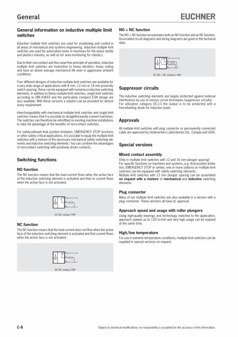
C-6
General
Subject to technical modifications; no responsibility is accepted for the accuracy of this information.
NO + NC functionThe NO + NC function incorporates both an NO function and an NC function.Associated circuit diagrams and wiring diagrams are given in the technical data.
1
4
3
2
DC NO + NC contacts, PNP
Suppressor circuits
The inductive switching elements are largely protected against external interference by use of various circuit techniques (suppressor circuits).For utilization category DC-13 the output is to be protected with a free-wheeling diode for inductive loads.
Approvals
All multiple limit switches with plug connector or permanently connected cable are approved by Underwriters Laboratories (UL, Canada and USA).
Special versions
Mixed contact assembly(Only in multiple limit switches with 12 and 16 mm plunger spacing)For specific functions on machines and systems, e.g. final position limita-tion, EMERGENCY STOP or similar, one or more stations on multiple limit switches can be equipped with safety switching elements.Multiple limit switches with 12 mm plunger spacing can be assembled on request with a mixture of mechanical and inductive switching elements.
Plug connectorMany of our multiple limit switches are also available in a version with a plug connector. These versions all have UL approval.
Approach speed and usage with roller plungersUsing high-quality bearings and technology matched to the application, approach speeds up to 120 m/min and very high usage can be realized at the same time.
High/low temperatureFor use in extreme temperature conditions, multiple limit switches can be supplied in special versions on request.
General information on inductive multiple limit switches
Inductive multiple limit switches are used for positioning and control in all areas of mechanical and systems engineering. Inductive multiple limit switches are used for automation tasks in machines for the wood, textile and plastics industry, as well as for area monitoring for robotics.
Due to their non-contact and thus wear-free principle of operation, inductive multiple limit switches are insensitive to heavy vibration, heavy soiling and have an above average mechanical life even in aggressive ambient conditions.
Four different designs of inductive multiple limit switches are available for a very wide range of applications with 8 mm, 12 mm or 16 mm proximity switch spacing; these can be equipped with numerous inductive switching elements. In addition to these multiple limit switches, single limit switches according to DIN 43693 and the particularly compact ESN design are also available. With these versions a solution can be provided for almost every requirement.
Interchangeability with mechanical multiple limit switches and single limit switches means that it is possible to straightforwardly convert machines. The switches can therefore be retrofitted on existing machine installations to take full advantage of the benefits of non-contact switches.
For safety-relevant final position limitation, EMERGENCY STOP functions or other safety critical applications, it is possible to equip the multiple limit switches with a mixture of the necessary mechanical safety switching ele-ments and inductive switching elements. You can combine the advantages of non-contact switching with positively driven contacts.
Switching functions
NO functionThe NO function means that the load current flows when the active face of the inductive switching element is activated and that no current flows when the active face is not activated.
1
4
3
DC NO contact, PNP
NC functionThe NC function means that the load current does not flow when the active face of the inductive switching element is activated and that current flows when the active face is not activated.
1
2
3
DC NC contact, PNP
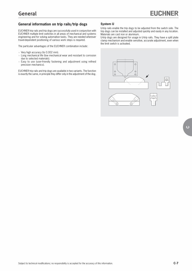
C-7
General
Subject to technical modifications; no responsibility is accepted for the accuracy of this information.
C
General information on trip rails/trip dogs
EUCHNER trip rails and trip dogs are successfully used in conjunction with EUCHNER multiple limit switches in all areas of mechanical and systems engineering and for solving automation tasks. They are needed wherever travel-dependent positioning of various work steps is required.
The particular advantages of the EUCHNER combination include:
Very high accuracy (to 0.002 mm). Long mechanical life (low mechanical wear and resistant to corrosion due to selected materials).
Easy to use (user-friendly fastening and adjustment using refined precision mechanics).
EUCHNER trip rails and trip dogs are available in two variants. The function is exactly the same, in principle they differ only in the adjustment of the dog.
System UU-trip rails enable the trip dogs to be adjusted from the switch side. The trip dogs can be installed and adjusted quickly and easily in any location. Materials are cast iron or aluminum.U-trip dogs are designed for usage in U-trip rails. They have a split plate clamp mechanism and enable sensitive, accurate adjustment, even when the limit switch is activated.

C-8
Multiple Limit Switches
Subject to technical modifications; no responsibility is accepted for the accuracy of this information.
Selection table for mechanical precision multiple limit switches
Series (here only preferable series: for other series see catalog)
RGBF Standard switch according to DIN 43697, upright housing, large product range
SN Compact upright housing; high market acceptance due to versatile applications, low cost
GSBF Upright housing
GLBF Horizontal housing
Plunger spacing (mm)
8 Small housing for installations where there is little space
12 Industry standard, large product range
16 Necessary only in special applications
Plunger types
D Chisel plunger for high operating point accuracy
R Roller plunger for approach speeds up to max. 80 m/min
B Roller plunger for approach speeds up to max. 120 m/min
K Ball plunger; necessary only in special applications
W Dome plunger; necessary only in special applications
Switching element
502 1 NC + 1 NO, precision snap-action switching element
508 1 NC , safety switching element, slow-action switching contact
514 1 NC + 1 NO, safety switching element, snap-ac-tion switching contact
552 1 C/O, snap-action switching contact (standard)
614 1 C/O, snap-action switching contact for low currents
Options
AM Exterior diaphragm
ST Plug connector
LED LED indicator
Series Plunger spac-ing Plunger types Switching element Options
PageRGBF SN GSBF GLBF 8 12 16 D R B K W 502 508 514 552 614 AM St LED
C-10
C-21
C-10
C-14
C-12
C-22
C-12
C-17
C-15
C-15
C-20
C-18
C-18
Available Available on request

C-9
Multiple Limit Switches
Subject to technical modifications; no responsibility is accepted for the accuracy of this information.
C
Selection table for inductive multiple limit switches
Series (here only preferable series: for other series see catalog)
RGBF Standard switch according to DIN 43697, upright housing, large product range
SN Compact upright housing; high market acceptance due to versatile applications, low cost
Proximity switch spacing (mm)
12 Rated operating distance 2 mm, industry standard, large product range
16 Rated operating distance 5 mm; necessary only in special applications
Switching element
772 DC NO + NC contacts, PNP
777 DC NO contact, PNP
779 DC NO contact, PNP
780 DC NO + NC contacts, NPN
781 DC NO + NC contacts, PNP
St Plug connector
LED LED indicator
SeriesProximity
switch spacing
Switching element OptionsPage
RGBF SN 12 16 772 777 779 780 781 St LED
C-11
C-11
C-13
C-13
Available Available on request

C-10
Multiple Limit Switches
Subject to technical modifications; no responsibility is accepted for the accuracy of this information.
40
72
80
6,6
6
22
850
37
45
6±
0,1
8m
ax.
70
30°
max.
5-1
,5
100
14
l 2
120 85
50
80
50
l 1
30n
ø10
LED
Dimension drawing Illustration with chisel plunger; plunger type depending on version
Switching elements
Plunger spacing 12 or 16 mm Upright housing according to DIN 43697
Degree of protection IP 67 according to IEC 60529
LED function display optional
Switching elements ES 502 E Snap-action switching contact
1 NC + 1 NO ES 508 Slow-action switching contact
1 NC ES 514 Snap-action switching contact
1 NC + 1 NO
On the usage of safety switching elements, the dog distance 4 -0.5 must be maintained to achieve the positively driven travel. The dogs must be positively mounted according to EN ISO 14119, i.e. riveted, welded or secured in some other way against becoming loose.
LED function display (optional)Function displays are available for the following voltage ranges (see accessories page C-23):
LE060 12 ... 60 V AC/DC LE110 110 V AC ±15% LE220 220 V AC ±15%
Series RGBF... mechanicalPlunger spacing 12 or 16 mm
Plunger types
D
Chisel
R
Roller(plain
bearing)
B
Roller(ball bearing)
K 4)
Ball 3)
W 4
Dome
Operating point accuracy 1) ± 0.002 ± 0.01 ± 0.01 ± 0.01 ± 0.002 mmApproach speed, max. 2) 40 80 120 10 10 m/min
1) The reproducible operating point accuracy refers to the axial travel of the plunger after the switching element ES 502 E has been run-in with approx. 2,000 operating cycles2) The approach speed specified applies in conjunction with EUCHNER trip dogs according to DIN 69639. Special versions of roller plungers for high usage on request3) For safety reasons, multiple limit switches with switching elements ES 508 and ES 514 are not available with ball plungers4) Plunger type on request
Series RGBF... 12/16 mm, mechanical
nNumber of plungers/prox-
imity switches
Plunger/proximity switch spacingl1 = 12 l1 = 16
l2 Housing material l2 Housing material2 70
Die-cast aluminum, anodized
70
Die-cast aluminum, anodized
3 80 90
4 90 105
5 105 120
6 120 140
8 140 170
Groove with sealing ring
Cable entry M25 x 1.5
Ope
ratin
g po
int
Free
po
sitio
n
Cable entry M25 x 1.5
4-0
.5
Stipulated dog distance for safety switching elements
Reference surface Dog
Version with LED function display
13
14
21
22
ES 502 E
Snap-action switching contact
13
14
21
22
ES 514
Snap-action switching contact
21
22
ES 508
Slow-action switching contact
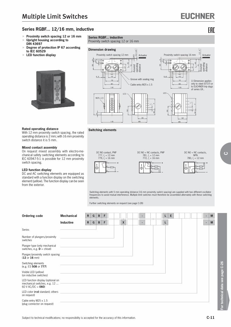
C-11
Multiple Limit Switches
For
tech
nica
l dat
a se
e pa
ge C
-26
Subject to technical modifications; no responsibility is accepted for the accuracy of this information.
C
Series RGBF... 12/16 mm, inductive
n
LED
l 1
0,2
- 4 1)
M25 x 1,5
LED
0,2
- 1,6
1)
nl 1
Dimension drawing
Switching elements
Proximity switch spacing 12 or 16 mm Upright housing according to DIN 43697
Degree of protection IP 67 according to IEC 60529
LED function display
Rated operating distanceWith 12 mm proximity switch spacing, the rated operating distance is 2 mm; with 16 mm proximity switch distance it is 5 mm.
Mixed contact assemblyOn request mixed assembly with electro-me-chanical safety switching elements according to IEC 60947-5-1 is possible for 12 mm proximity switch spacing.
LED function displayDC and AC switching elements are equipped as standard with a function display on the switching element (yellow). The function display can be seen from the exterior.
Series RGBF... inductiveProximity switch spacing 12 or 16 mm
Ordering code Mechanical R G B F - L E - M
Inductive R G B F X - L - M
Series
Number of plungers/proximity switches
Plunger type (only mechanical switches, e.g. D = chisel)
Plunger/proximity switch spacing(12 or 16 mm)
Switching elements(e.g. ES 508 or 777)
Visible LED (yellow) (on inductive switches)
LED function display (optional on mechanical switches, e.g. 12 ... 60 V AC/DC = 060)
LED color (red standard; others on request)
Cable entry M25 x 1.5 (plug connector on request)
1
4
3
DC NO contact, PNP777, l1 = 12 mm779, l1 = 16 mm
1
4
3
2
DC NO + NC contacts, PNP781, l1 = 12 mm772, l1 = 16 mm
1
4
3
2
DC NO + NC contacts, NPN
780, l1 = 12 mm
Switching elements with 5 mm operating distance (16 mm proximity switch spacing) are supplied with two different oscillator frequencies to avoid mutual interference. Multiple limit switches must therefore be assembled alternately with these switching elements.
Further switching elements on request (see page C-28)
Groove with sealing ring
Cable entry M25 x 1.5
Assu
red
oper
atin
g di
stan
ce
1) Dimension applies only to steel (ST37) or to EUCHNER trip dogs of series UX..
Actuator Actuator
Assu
red
oper
atin
g di
stan
ce
Proximity switch spacing 12 mm Proximity switch spacing 16 mm

C-12
Multiple Limit Switches
Subject to technical modifications; no responsibility is accepted for the accuracy of this information.
30°
max.ø104
50
60
5 6,5
max
.
6,6
812
4-1
.5
10
l
75
36
60
l 1
l 3n
100
LED
85
2
l 4
M20
x1,5
LED
Dimension drawing Illustration with chisel plunger; plunger type depending on version
Plunger spacing 12 or 16 mm Upright housing, small flange Degree of protection IP 67 according to IEC 60529
LED function display optional
Switching elements ES 502 E Snap-action switching contact
1 NC + 1 NO ES 508 Slow-action switching contact
1 NC ES 514 Snap-action switching contact
1 NC + 1 NO
On the usage of safety switching elements, the dog distance 3 -0.5 must be maintained to achieve the positively driven travel. The dogs must be positively mounted according to EN ISO 14119, i.e. riveted, welded or secured in some other way against becoming loose.
LED function display (optional)Function displays are available for the following voltage ranges (see accessories page C-23):
LE024ge 24 V DC (for ES 514) LE060 12 ... 60 V AC/DC LE110 110 V AC ±15% LE220 220 V AC ±15%
Series SN... mechanicalPlunger spacing 12 or 16 mm
Series SN... 12/16 mm, mechanical
nNumber of plungers/prox-
imity switches
Plunger/proximity switch spacingHousing materiall1 = 12 l1 = 16
l2 l3 l4 l2 l3 l42 36
12
19 48
16 24Die-cast aluminum, anod-
ized
3 48
24
72
4 60 84
5 72 - - -
6 84 - - -
Cable entry M20 x 1.5O
pera
ting
poin
tFr
ee
posi
tion
3-0
.5
Stipulated dog distance for safety switching elements
Reference surface Dog
Version with LED function display
Version with safety switching element ES 514 and LED function display LE024
Switching elements
Plunger types
D
Chisel
R
Roller(plain
bearing)
B
Roller(ball bearing)
K 4)
Ball 3)
W 4
Dome
Operating point accuracy 1) ± 0.002 ± 0.01 ± 0.01 ± 0.01 ± 0.002 mmApproach speed, max. 2) 40 80 120 10 10 m/min
1) The reproducible operating point accuracy refers to the axial travel of the plunger after the switching element ES 502 E has been run-in with approx. 2,000 operating cycles2) The approach speed specified applies in conjunction with EUCHNER trip dogs according to DIN 69639. Special versions of roller plungers for high usage on request3) For safety reasons, multiple limit switches with switching elements ES 508 and ES 514 are not available with ball plungers4) Plunger type on request
13
14
21
22
ES 502 E
Snap-action switching contact
13
14
21
22
ES 514
Snap-action switching contact
21
22
ES 508
Slow-action switching contact

C-13
Multiple Limit Switches
For
tech
nica
l dat
a se
e pa
ge C
-26
Subject to technical modifications; no responsibility is accepted for the accuracy of this information.
C
Series SN... 12/16 mm, inductive
M20
x 1
,5
LED
l 1
l 3l 4
l 1
l 3
M20
x 1
,5
l
LED
Dimension drawing
Proximity switch spacing 12 or 16 mm Upright housing, small flange Degree of protection IP 67 according to IEC 60529
LED function display
Rated operating distanceWith 12 mm proximity switch spacing, the rated operating distance is 2 mm; with 16 mm proximity switch distance it is 5 mm.
Mixed contact assemblyOn request mixed assembly with electro-me-chanical safety switching elements according to IEC 60947-5-1 is possible for 12 mm proximity switch spacing.
LED function displayDC and AC switching elements are equipped as standard with a function display on the switching element (yellow). The function display can be seen from the exterior.
Series SN... inductiveProximity switch spacing 12 or 16 mm
Ordering code Mechanical S N - L E - M
Inductive S N X - L - M
Series
Number of plungers/proximity switches
Plunger type (only mechanical switches, e.g. D = chisel)
Plunger/proximity switch spacing(12 or 16 mm)
Switching elements(e.g. ES 508 or 777)
Visible LED (yellow)(on inductive switches)
LED function display (optional on mechanical switches, e.g. 12 ... 60 V AC/DC = 060)
LED color (red standard; others on request)
Cable entry M20 x 1.5 (plug connector on request)
Cable entry M20 x 1.5
Assu
red
oper
atin
g di
stan
ce
1) Dimension applies only to steel (ST37) or to EUCHNER trip dogs of series UX..
Actuator
Switching elements
1
4
3
DC NO contact, PNP777, l1 = 12 mm779, l1 = 16 mm
1
4
3
2
DC NO + NC contacts, PNP781, l1 = 12 mm772, l1 = 16 mm
1
4
3
2
DC NO + NC contacts, NPN
780, l1 = 12 mm
Switching elements with 5 mm operating distance (16 mm proximity switch spacing) are supplied with two different oscillator frequencies to avoid mutual interference. Multiple limit switches must therefore be assembled alternately with these switching elements.
Further switching elements on request (see page C-28)
Actuator
Proximity switch spacing 12 mm Proximity switch spacing 16 mm
Assu
red
oper
atin
g di
stan
ce

C-14
Multiple Limit Switches
Subject to technical modifications; no responsibility is accepted for the accuracy of this information.
30°
max.
9,5
3
4m
ax.
2±
0,5
4,5
ø8
40
ø4,5
25l 1
26
42
8
13n
ø6
Dimension drawing Illustration with chisel plunger; plunger type depending on version
Switching elements
Plunger spacing 8 mm Upright housing, without flange Degree of protection IP 67 according to IEC 60529
Series SN... mechanicalPlunger spacing 8 mm
Plunger types
D
Chisel
R
Roller(plain bearing)
Cl
Ball
Operating point accuracy 1) ± 0.02 ± 0.05 ± 0.03 mmApproach speed, max. 2) 20 50 8 m/min
1) The reproducible operating point accuracy refers to the axial travel of the plunger after the switching element ES 552 E has been run-in with approx. 2,000 operating cycles2) The approach speed specified applies in conjunction with EUCHNER trip dogs according to DIN 69639
Series SN... 8 mm, mechanical
nNumber of plungers
Plunger spacing 8 mml1 Cable entry Housing material
2 34
M16 x 1.5
Die-cast aluminum, anodized
3 42
4 50
5 58M20 x 1.5
6 66
Cabl
e en
try
met
ric
Ope
ratin
g po
int
Free
po
sitio
n
Reference surface Dog
Cable entry
Switching elements ES 552 Snap-action switching contact
1 changeover contact Standard switching element
ES 614 Snap-action switching contact 1 changeover contact Suitable for switching low cur-rents
(See technical data on the switching elements)
1
2
4
ES 552
Snap-action switching contact
1
2
4
ES 614
Snap-action switching contact
Ordering code Mechanical S N 0 8 - - M
Series
Number of plungers
Plunger type (e.g. D = chisel)
Plunger spacing(8 mm)
Switching element(ES 552 or ES 614)
Cable entry with metric thread(plug connector on request)

C-15
Multiple Limit Switches
For
tech
nica
l dat
a se
e pa
ge C
-26
Subject to technical modifications; no responsibility is accepted for the accuracy of this information.
C
6 8m
ax.
30°
max.
5-1
,5
l 1
30n
30
45
26
40
80
82
98
6,6
4
22
828
14
l2
115
45
36
68 (95) * 100
ø10
LED
Dimension drawing Illustration with chisel plunger; plunger type depending on version
Switching elements
Plunger spacing 12 or 16 mm Upright housing Degree of protection IP 67 according to IEC 60529
LED function display optional
Switching elements ES 502 E Snap-action switching contact
1 NC + 1 NO ES 508 Slow-action switching contact
1 NC ES 514 Snap-action switching contact
1 NC + 1 NO
On the usage of safety switching elements, the dog distance 4 -0.5 must be maintained to achieve the positively driven travel. The dogs must be positively mounted according to EN ISO 14119, i.e. riveted, welded or secured in some other way against becoming loose.
LED function display (optional)Function displays are available for the following voltage ranges (see accessories page C-23):
LE060 12 ... 60 V AC/DC LE110 110 V AC ±15% LE220 220 V AC ±15%
Series GSBF... mechanicalPlunger spacing 12 or 16 mm
Plunger types
D
Chisel
R
Roller(plain bearing)
K 4)
Ball 3)
W 4)
Dome
Operating point accuracy 1) ± 0.002 ± 0.01 ± 0.01 ± 0.002 mmApproach speed max. 2) 40 80 10 10 m/min
1) The reproducible operating point accuracy refers to the axial travel of the plunger after the switching element ES 502 E has been run-in with approx. 2,000 operating cycles2) The approach speed specified applies in conjunction with EUCHNER trip dogs according to DIN 696393) For safety reasons, multiple limit switches with switching elements ES 508 and ES 514 are not available with ball plungers4) Plunger type on request
Series GSBF... 12/16 mm, mechanical
nNumber of plungers
Plunger spacingHousing materiall1 = 12 l1 = 16
l2 l22 70 70
Die-cast aluminum, anodized
3 70 82
4 82 96
5 96 112
6 112 130
8 130 -
Groove with sealing ring
Cable entryM25 x 1.5 O
pera
ting
poin
tFr
ee
posi
tion
Cable entry M25 x 1.5
4-0
.5
Stipulated dog distance for safety switching elements
Reference surface Dog
Version with LED function display
* Only with switching element ES 514
13
14
21
22
ES 502 E
Snap-action switching contact
13
14
21
22
ES 514
Snap-action switching contact
21
22
ES 508
Slow-action switching contact

C-16
Multiple Limit Switches
Subject to technical modifications; no responsibility is accepted for the accuracy of this information.
Ordering code Mechanical G S B F - L E - M
Series
Number of plungers
Plunger type (e.g. D = chisel)
Plunger spacing(12 or 16 mm)
Switching elements(e.g. ES 508)
LED function display (optional, e.g. 12 ... 60 V AC/DC = 060)
LED color (red standard; others on request)
Cable entry M25 x 1.5

C-17
Multiple Limit Switches
For
tech
nica
l dat
a se
e pa
ge C
-26
Subject to technical modifications; no responsibility is accepted for the accuracy of this information.
C
30°
max.
121438
45
57
ø6
22
3 4m
ax.
16
l 1
ø5,5
72
ø10
10
28
45
30
8
26n
2±
0,5
Dimension drawing Illustration with chisel plunger; plunger type depending on version
Plunger spacing 8 mm Upright housing Degree of protection IP 67 according to IEC 60529
Series GSBF... mechanicalPlunger spacing 8 mm
Series GSBF... 8 mm, mechanical
nNumber of plungers/proximity switches
Plunger/proximity switch spacing 8 mml1 Housing material
2 48
Sand-cast aluminum, anodized
3 64
4 64
5 80
6 80
Cable entry M20 x 1.5
Ope
ratin
g po
int
Free
po
sitio
n
Reference surface Dog
Cable entry M20 x 1.5
Switching elements
Plunger types
D
Chisel
R
Roller(plain bearing)
K 4)
Ball
Operating point accuracy 1) ± 0.02 ± 0.05 ± 0.03 mmApproach speed, max. 2) 20 50 8 m/min
1) The reproducible operating point accuracy refers to the axial travel of the plunger after the switching element ES 552 E has been run-in with approx. 2,000 operating cycles2) The approach speed specified applies in conjunction with EUCHNER trip dogs according to DIN 696393) Plunger type on request
Switching elements ES 552 Snap-action switching contact
1 changeover contact Standard switching element
ES 614 Snap-action switching contact 1 changeover contact Suitable for switching low cur-rents
(See technical data on the switching elements)
1
2
4
ES 552
Snap-action switching contact
1
2
4
ES 614
Snap-action switching contact
Ordering code Mechanical G S B F 0 8 - - M
Series
Number of plungers/proximity switches
Plunger type (only mechanical switches, e.g. D = chisel)
Plunger/proximity switch spacing(8 mm)
Switching element(ES 552 or ES 614)
Cable entry M20 x 1.5

C-18
Multiple Limit Switches
Subject to technical modifications; no responsibility is accepted for the accuracy of this information.
l 1
n
40
l 3
4
23
830
B A C
30
50
20
50
90
l 4
ø6,6
l 2
14
ø11
10038
56
6
8 max.
30°
max
.
ø10
LED
5 -1,5
62 (95) *
Dimension drawing Illustration with chisel plunger; plunger type depending on version
Plunger spacing 12 or 16 mm Horizontal housing Degree of protection IP 67 according to IEC 60529
LED function display optional
Switching elements ES 502 E Snap-action switching contact
1 NC + 1 NO ES 508 Slow-action switching contact
1 NC ES 514 Snap-action switching contact
1 NC + 1 NO
On the usage of safety switching elements, the dog distance 4 -0.5 must be maintained to achieve the positively driven travel. The dogs must be positively mounted according to EN ISO 14119, i.e. riveted, welded or secured in some other way against becoming loose.
LED function display (optional)Function displays are available for the following voltage ranges (see accessories page C-23):
LE060 12 ... 60 V AC/DC LE110 110 V AC ±15% LE220 220 V AC ±15%
Series GLBF... mechanicalPlunger spacing 12 or 16 mm
Series GLBF... 12/16 mm, mechanical (on request)
nNumber of plungers/
proximity switches
Plunger/proximity switch spacingHousing materiall1 = 12 l1 = 16
l2 l3 l4 Cable entry l2 l3 l4 Cable entry2 84 66 52
AM25 x 1.5
84 66 52 AM25 x 1.5
Sand-cast aluminum, an-odized
3 84 66 52 100 82 68
4 100 82 68 114 98 84B + C
M25 x 1.55 114 98 84 B + C M25 x 1.5
132 114 100
6 132 114 100 148 130 116
Cable entry M25 x 1.5
Operating pointFree position
Cable entry M25 x 1.5
4-0
.5
Stipulated dog distance for safety switching elementsReference surface
Dog
Version with LED function display
* Only with switching element ES 514
Switching elements
Plunger types
D
Chisel
R
Roller(plain bearing)
K 4)
Ball 3)
W 4)
Dome
Operating point accuracy 1) ± 0.002 ± 0.01 ± 0.01 ± 0.002 mmApproach speed max. 2) 40 80 10 10 m/min
1) The reproducible operating point accuracy refers to the axial travel of the plunger after the switching element ES 502 E has been run-in with approx. 2,000 operating cycles2) The approach speed specified applies in conjunction with EUCHNER trip dogs according to DIN 696393) For safety reasons, multiple limit switches with switching elements ES 508 and ES 514 are not available with ball plungers4) Plunger type on request
13
14
21
22
ES 502 E
Snap-action switching contact
13
14
21
22
ES 514
Snap-action switching contact
21
22
ES 508
Slow-action switch-ing contact

C-19
Multiple Limit Switches
For
tech
nica
l dat
a se
e pa
ge C
-26
Subject to technical modifications; no responsibility is accepted for the accuracy of this information.
C
Ordering code Mechanical G L B F - L E - M
Series
Number of plungers/proximity switches
Plunger type (only mechanical switches, e.g. D = chisel)
Plunger/proximity switch spacing(12 or 16 mm)
Switching elements(e.g. ES 508)
Visible LED yellow(on inductive switches)
LED function display (optional on mechanical switches, e.g. 12 ... 60 V AC/DC = 060)
LED color (red standard; others on request)
Cable entry M25 x 1.5

C-20
Multiple Limit Switches
Subject to technical modifications; no responsibility is accepted for the accuracy of this information.
8
n
1214
l 2
22
38
l 3
16
32
55
10
ø5,5
l 1
ø10
30°
max
.
38
28
45
ø6
3
4 max.
2±0,5
Dimension drawing Illustration with chisel plunger; plunger type depending on version
Plunger spacing 8 mm Horizontal housing Degree of protection IP 67 according to IEC 60529
Series GLBF... mechanicalPlunger spacing 8 mm
Series GLBF... 8 mm, mechanical
nNumber of plungers/proximity switches
Plunger/proximity switch spacing 8 mmHousing material
l1 l2 l32 64 50 39
Sand-cast aluminum, anodized3 80 66 55
4 80 66 55
Cable entry M20 x 1.5 Operating point
Free position
Reference surface
Dog
M20 x 1.5
Switching elements
Plunger types
D
Chisel
R
Roller(plain bearing)
K 3)
Ball
Operating point accuracy 1) ± 0.02 ± 0.05 ± 0.03 mmApproach speed, max. 2) 20 50 8 m/min
1) The reproducible operating point accuracy refers to the axial travel of the plunger after the switching element ES 552 E has been run-in with approx. 2,000 operating cycles2) The approach speed specified applies in conjunction with EUCHNER trip dogs according to DIN 696393) Plunger type on request
Switching elements ES 552 Snap-action switching contact
1 changeover contact Standard switching element
(See technical data on the switching elements) 1
2
4
ES 552
Snap-action switching contact
Ordering code Mechanical G L B F 0 8 - 5 5 2 - M
Series
Number of plungers/proximity switches
Plunger type (only mechanical switches, e.g. D = chisel)
Plunger/proximity switch spacing(8 mm)
Switching element ES 552
Cable entry M20 x 1.5
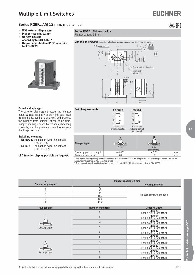
C-21
Multiple Limit Switches
For
tech
nica
l dat
a se
e pa
ge C
-26
Subject to technical modifications; no responsibility is accepted for the accuracy of this information.
C
40
72
80
6,6
6
22
850
37
45
6±
0 ,1
8m
ax.
70
30°
max.
5-1
,5
100
14120
50
80
50
l 1
30n
ø7
12
Dimension drawing Illustration with chisel plunger; plunger type depending on version
Switching elements
With exterior diaphragm Plunger spacing 12 mm Upright housing according to DIN 43697
Degree of protection IP 67 according to IEC 60529
Series RGBF... AM mechanicalPlunger spacing 12 mm
Plunger types
D
Chisel
R
Roller(plain bearing)
Operating point accuracy 1) ± 0.002 ± 0.01 mmApproach speed, max. 2) 20 50 m/min
1) The reproducible operating point accuracy refers to the axial travel of the plunger after the switching element ES 502 E has been run-in with approx. 2,000 operating cycles2) The approach speed specified applies in conjunction with EUCHNER trip dogs according to DIN 69639
Series RGBF...AM 12 mm, mechanical
nNumber of plungers
Plunger spacing 12 mml1 Housing material
2 70
Die-cast aluminum, anodized
3 804 905 1056 1208 140
Cable entry M25 x 1.5
Ope
ratin
g po
int
Free
po
sitio
n
Reference surfaceDog
Plunger type Number of plungers Order no./item
D
Chisel plunger
2 082325RGBF 02 D 12 -502 AM -M
3 088365RGBF 03 D 12 -502 AM -M
4 082326RGBF 04 D 12 -502 AM -M
5 088366RGBF 05 D 12 -502 AM -M
6 087097RGBF 06 D 12 -502 AM -M
R
Roller plunger
2 087098RGBF 02 R 12 -502 AM -M
3 088364RGBF 03 R 12 -502 AM -M
4 082327RGBF 04 R 12 -502 AM -M
5 087099RGBF 05 R 12 -502 AM -M
6 087100RGBF 06 R 12 -502 AM -M
Exterior diaphragmThe exterior diaphragm protects the plunger guide against the entry of very fine dust (dust from grinding, casting, glass, etc.) and prevents the plunger from seizing. At the same time, plunger sticking, caused by resinous lubricating coolants, can be prevented with this exterior diaphragm version.
Switching elements ES 502 E Snap-action switching contact
1 NC + 1 NO ES 514 Snap-action switching contact
1 NC + 1 NO
LED function display possible on request.
Groove with sealing ring
Cable entry M25 x 1.5
13
14
21
22
ES 502 E
Snap-action switching contact
13
14
21
22
ES 514
Snap-action switching contact
(on request)

C-22
Multiple Limit Switches
Subject to technical modifications; no responsibility is accepted for the accuracy of this information.
l 1
12
12
30°
max.
4
50
60
5
6,5
max
.
6,6
812
4-1
.5
1075
36
60
l 2
n
ø7
Dimension drawing Illustration with chisel plunger; plunger type depending on version
Switching elements
With exterior diaphragm Plunger spacing 12 mm Upright housing, small flange Degree of protection IP 67 according to IEC 60529
Series SN...AM mechanicalPlunger spacing 12 mm
Plunger types
D
Chisel
R
Roller(plain bearing)
Operating point accuracy 1) ± 0.002 ± 0.01 mmApproach speed, max. 2) 20 50 m/min
1) The reproducible operating point accuracy refers to the axial travel of the plunger after the switching element ES 502 E has been run-in with approx. 2,000 operating cycles2) The approach speed specified applies in conjunction with EUCHNER trip dogs according to DIN 69639
Series SN...AM 12 mm, mechanical
nNumber of plungers
Plunger spacing 12 mml1 l2 Housing material
2 36 19
Die-cast aluminum, anodized3 48
244 605 726 84
Cable entry M20 x 1.5
Ope
ratin
g po
int
Free
po
sitio
n
Reference surface Dog
Plunger type Number of plungers Order no./item
D
Chisel plunger
2 086584SN 02 D 12 -502 AM -M
3 086585SN 03 D 12 -502 AM -M
4 086586SN 04 D 12 -502 AM -M
5 088752SN 05 D 12 -502 AM -M
6 088753SN 06 D 12 -502 AM -M
R
Roller plunger
2 079289SN 02 R 12 -502 AM -M
3 086587SN 03 R 12 -502 AM -M
4 086588SN 04 R 12 -502 AM -M
5 088765SN 05 R 12 -502 AM -M
6 088766SN 06 R 12 -502 AM -M
Exterior diaphragmThe exterior diaphragm protects the plunger guide against the entry of very fine dust (dust from grinding, casting, glass, etc.) and prevents the plunger from seizing. At the same time, plunger sticking, caused by resinous lubricating coolants, can be prevented with this exterior diaphragm version.
Switching elements ES 502 E Snap-action switching contact
1 NC + 1 NO
LED function display possible on request.
13
14
21
22
ES 502 E
Snap-action switching contact

C-23
Multiple Limit Switches
For
tech
nica
l dat
a se
e pa
ge C
-26
Subject to technical modifications; no responsibility is accepted for the accuracy of this information.
C
Figure
LED function display LED function display
Ordering table
Designation Operating voltage [V] Color Order no./item
LED function display 1)
AC/DC 12 - 60
Red 035495LE 060 rt
Green 035496LE 060 gr
Yellow 035497LE 060 ge
AC 110 ±15% Red 045579LE 110 rt
AC 220 ±15%Red 045582
LE 220 rt
Yellow 045584LE 220 ge
1) If color not stated, red will be supplied as standard
Accessories for mechanical multiple limit switches
Ordering table
Designation Order no./item
Replacement switching elements
010387ES 502 E099513ES 552099507ES 614
Replacement mechanical switching elements
Figure
Replacement switching elements
ES 502 E ES 552/ES 614
LED function displayThree versions in various voltage ranges are avail-able in the standard colors red, green and yellow.The built-in electronic regulation (LE060 only) ensures that the luminosity remains constant, independent of the voltage applied.
Replacement switching elementsReplacement switching elements for multiple limit switches with 8, 12 and 16 mm plunger spacing.
The safety switching elements ES 508 and ES 514 are not allowed to be replaced for safety reasons and are therefore not avail-able as spare parts. In safety circuits, the entire multiple limit switch must be replaced in case of damage or wear. Repairs are to be made only by the manufacturer.

C-24
Multiple Limit Switches
Subject to technical modifications; no responsibility is accepted for the accuracy of this information.
Ordering table
Designation Bridge Function Order no.
ES777 12 mm NO contact/PNP 008401ES781 12 mm NO + NC contacts/PNP 031535ES780 12 mm NO + NC contacts/NPN 031534
ES779 1) 16 mm NO contact/PNP 008470ES779/2 1) 16 mm NO contact/PNP 036731ES772 1) 16 mm NO + NC contacts/PNP 053674
ES772/2 1) 16 mm NO + NC contacts/PNP 053677
1) Switching elements with 5 mm operating distance (proximity switch spacing 16 mm) are supplied with two different oscillator frequencies to avoid mutual interference. Multiple limit switches must therefore be assembled alternately with these switching elements.
Accessories for inductive multiple limit switches Replacement inductive switching elements
The switching elements used for all inductive multiple limit switches supplied are available as spare parts

C-25
Multiple Limit Switches
For
tech
nica
l dat
a se
e pa
ge C
-26
Subject to technical modifications; no responsibility is accepted for the accuracy of this information.
C
E M
BA
SW
M16 x 1.5 M20 x 1.5 M25 x 1.5
Cable glandsSuitable for various cable diameters. Versions in metal.
Cable glands
Ordering table
Thread Version Order no./item
M16 x 1.5
Cable diameter4 - 6.5 mm
086328EKVM16/04
Cable diameter5 - 8 mm
086329EKVM16/05
Cable diameter6.5 - 9.5 mm
086330EKVM16/06
M20 x 1.5
Cable diameter6.5 - 9.5 mm
077683EKVM20/06
Cable diameter9 - 13 mm
077684EKVM20/09
M25 x 1.5
Cable diameter9 - 13 mm
086334EKVM25/09
Cable diameter11.5 - 15.5 mm
086335EKVM25/11
Cable glands
Item Thread Cable [mm]
A[mm]
B[mm]
E[mm]
SW[mm]
EKVM16/04 M16x1.5 4 - 6.5 20 6 20 18
EKVM16/05 M16x1.5 5 - 8 20 6 20 18
EKVM16/06 M16x1.5 6.5 - 9.5 20 6 20 18
EKVM20/06 M20x1.5 6.5 - 9.5 20 6 24.4 22
EKVM20/09 M20x1.5 9 - 13 21 6 24.4 22
EKVM25/09 M25x1.5 9 - 13 21 6.5 31.2 28
EKVM25/11 M25x1.5 11.5 - 15.5 21 6.5 31.2 28

C-26
Technical data
Subject to technical modifications; no responsibility is accepted for the accuracy of this information.
Multiple limit switches, mechanical
Parameter Value Unit
Switching elements ES 502 E 508 514 552 614
Degree of protection acc. to EN IEC 60529 IP 67
Installation position Any
Plunger material Stainless steel
Plunger guide Maintenance-free
Ambient temperature -5 ... +80 °C
Switching contacts 1 NO + 1 NC 1 NC 1 NO + 1
NC 1 changeover contact
Switching principle Snap-action switching cont.
Slow-action switching cont. Snap-action switching contact
Actuating force 20 15 30 15 N
Approach speed, min. 0.01 - 0.01 m/min
Differential travel 0.8 - 0.6 0.1 mm
Switching frequency 300 50 200 min-1
Mechanical life (operating cycles) 30 x 106 1 x 10⁶ 10 x 106
Rated impulse withstand voltage Uimp 2.5 4 2.5 kV
Rated insulation voltage Ui 250 V
Utilization category acc. to EN IEC 60947-5-1 AC-12 Ie 8 A Ue 250 V - - - -
AC-15 Ie 6 A Ue 230 V Ie 2.5 A Ue 230 V Ie 2 A Ue 230 V -
DC-13 Ie 6 A Ue 24 V Ie 2 A Ue 24 V Ie 1 A Ue 30 V
Switching current, min.,at switching voltage
1012
1024
524
1024
15
mAV DC
Conventional thermal current Ith 8 10 6 2 A
Contact closing time < 4 - 5 - ms
Contact bounce time < 3 - 3 2 ms
Short circuit prot. acc. to EN IEC 60269-1 (control circuit fuse) 8 10 6 2 A gG
Connection Screw terminal
Conductor cross-section, max. 0.34 ... 1.5 0.14 ... 1.0 mm²
Approvals for switching elements - -
LED function display (optional) Red standard; others on request LE024ge -
Travel diagramES 502 E
01234
67
5
6
8m
ax.
5-1
,5
7,5
13-1
421
-22
13-1
421
-22
0
1
2
3
4
6
5
5
6,5
max
.
1,5
4-1
,5
13-1
421
-22
13-1
421
-22
On series RGBF.../GSBF.../GLBF...Plunger spacing 12/16 mm
On series SN...Plunger spacing 12/16 mm
Free positionOperating point
Free positionOperating point
Contacts closed
Contacts open
Snap-action switching contact according to DIN 43695 with one NO and one NC contact. Double gap, electrically isolated switching contacts, silver contact material, electro-gold plated. Screw terminal with self-raising clamp washers.

C-27
Technical data
Subject to technical modifications; no responsibility is accepted for the accuracy of this information.
C
Travel diagramES 508
6
8m
ax.
0
2
3
4
55,5
1
4-0
,5
21-2
2
5
6,5
max
.
0
2
3
4
5
1
3,5
1,5
3-0
,5
21-2
2
On series RGBF.../GSBF.../GLBF...Plunger spacing 12/16 mm
On series SN...Plunger spacing 12/16 mm
Free positionOperating point
Free positionOperating point
Contacts closed
Contacts open
Contacts positively driven
Slow-action switching contact with one positively driven contact. Double gap, silver contact material, electro-gold plated. Screw terminal with self-raising clamp washers.
Travel diagramES 514
6
8m
ax.
13-1
421
-22
13-1
421
-22
0
1
2
3
4
5
4-0
,5
13-1
421
-22
13-1
421
-22
5
6,5
max
.0
1
2
3
44,5
1,5
3,5
3-0
,5
On series RGBF.../GSBF.../GLBF...Plunger spacing 12/16 mm
On series SN...Plunger spacing 12/16 mm
Free positionOperating point
Free positionOperating point
Contacts closed
Contacts open
Contacts positively driven
Magnetic snap-action switching contact with one positively driven contact and one NO contact. Double gap, electrically isolated switching contacts, silver contact material, electro-gold plated. Screw terminal with self-raising clamp washers.
Travel diagramES 552
1-2
1-4
0
1
2
3
3
4m
ax.
2±
0,5
On series GSBF.../GLBF.../SN.../SB...Plunger spacing 8 mm
Free positionOperating point
Travel diagramES 614
1-2
1-4
0
1
2
3
3
4m
ax.
2±
0,5
On series GSBF.../SN.../SB...Plunger spacing 8 mm
Free positionOperating point
Contacts closed
Contacts open
Contacts closed
Contacts open
Snap-action switching contact with one changeover contact.Silver contact material, electro-gold plated. Screw terminal.
Snap-action switching contact with one changeover contact. Silver contract material, electro-gold plated (gold cross cut contact). Screw terminal.
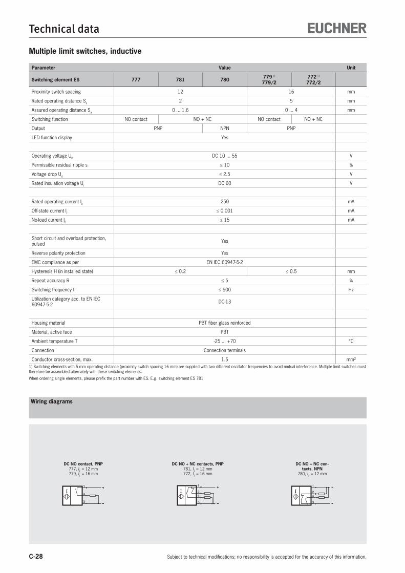
C-28
Technical data
Subject to technical modifications; no responsibility is accepted for the accuracy of this information.
Multiple limit switches, inductive
Parameter Value Unit
Switching element ES 777 781 780 779 1)
779/2772 1)
772/2
Proximity switch spacing 12 16 mm
Rated operating distance Sn 2 5 mm
Assured operating distance Sa 0 ... 1.6 0 ... 4 mm
Switching function NO contact NO + NC NO contact NO + NC
Output PNP NPN PNP
LED function display Yes
Operating voltage UB DC 10 ... 55 V
Permissible residual ripple s 10 %
Voltage drop Ud 2.5 V
Rated insulation voltage Ui DC 60 V
Rated operating current Ie 250 mA
Off-state current Ir 0.001 mA
No-load current I0 15 mA
Short circuit and overload protection, pulsed Yes
Reverse polarity protection Yes
EMC compliance as per EN IEC 60947-5-2
Hysteresis H (in installed state) 0.2 0.5 mm
Repeat accuracy R 5 %
Switching frequency f 500 Hz
Utilization category acc. to EN IEC 60947-5-2 DC-13
Housing material PBT fiber glass reinforced
Material, active face PBT
Ambient temperature T -25 ... +70 °C
Connection Connection terminals
Conductor cross-section, max. 1.5 mm²1) Switching elements with 5 mm operating distance (proximity switch spacing 16 mm) are supplied with two different oscillator frequencies to avoid mutual interference. Multiple limit switches must therefore be assembled alternately with these switching elements.
When ordering single elements, please prefix the part number with ES. E.g. switching element ES 781
1
4
3
DC NO contact, PNP777, l1 = 12 mm779, l1 = 16 mm
1
4
3
2
DC NO + NC contacts, PNP781, l1 = 12 mm772, l1 = 16 mm
1
4
3
2
DC NO + NC con-tacts, NPN
780, l1 = 12 mm
Wiring diagrams
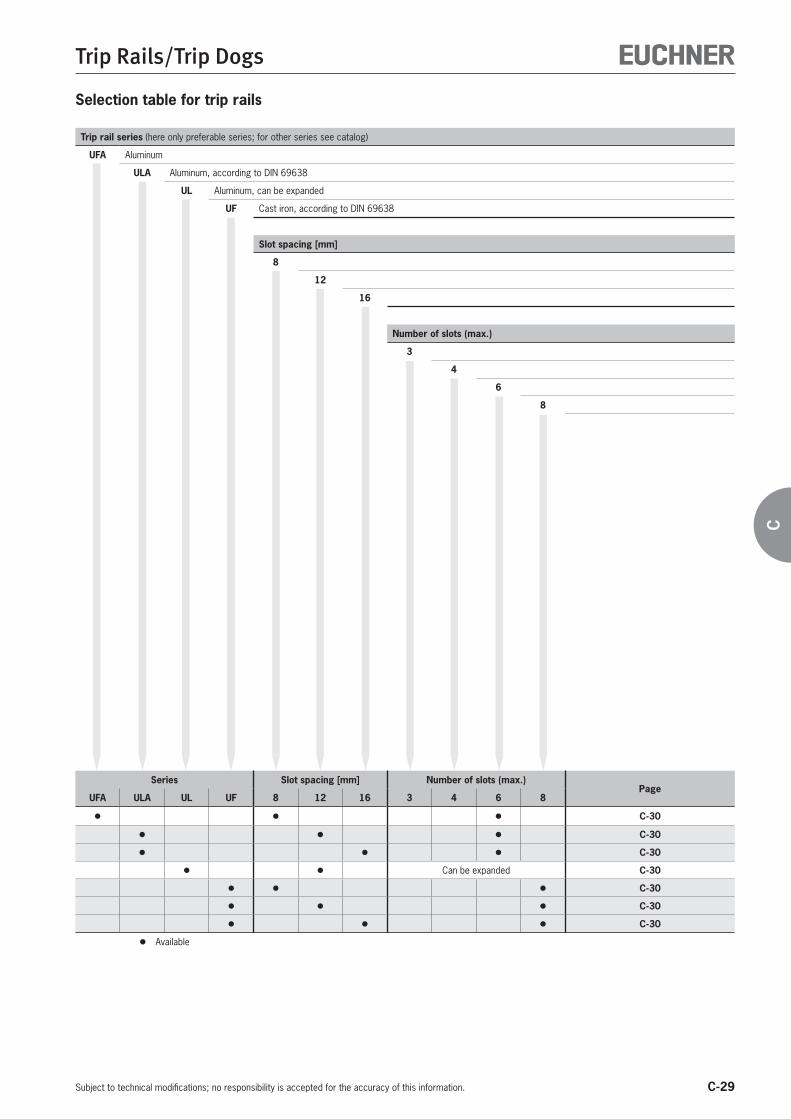
C-29
Trip Rails/Trip Dogs
Subject to technical modifications; no responsibility is accepted for the accuracy of this information.
C
Selection table for trip rails
Trip rail series (here only preferable series; for other series see catalog)
UFA Aluminum
ULA Aluminum, according to DIN 69638
UL Aluminum, can be expanded
UF Cast iron, according to DIN 69638
Slot spacing [mm]
8
12
16
Number of slots (max.)
3
4
6
8
Series Slot spacing [mm] Number of slots (max.)Page
UFA ULA UL UF 8 12 16 3 4 6 8
C-30
C-30
C-30
Can be expanded C-30
C-30
C-30
C-30
Available

C-30
Trip Rails/Trip Dogs
Subject to technical modifications; no responsibility is accepted for the accuracy of this information.
Trip rails with 8 mm, 12 mm or 16 mm spacing
Series UF... Slot spacing 8 mm, cast iron
a
a
Dimension drawing
Series UFA... Slot spacing 8 mm, aluminum
a
Series UF... according to DIN 69638 type ASlot spacing 12 mm, cast iron
a
a
Dimension drawing
Series ULA... according to DIN 69638 type ASlot spacing 12 mm, aluminum
Series UL... can be placed in a rowSlot spacing 12 mm, aluminum
Series UF... according to DIN 69638 type ASlot spacing 16 mm, cast iron
a
a
Dimension drawing
Series ULA... according to DIN 69638 type ASlot spacing 16 mm, aluminum
Dimension a [mm] 44 52 60 68 76
Number of slots 2 3 4 5 6
Minimum order 2,010 mm, 1 bar
Dimension a [mm] 44 52 60 68 76 92
Number of slots 2 3 4 5 6 8
Dimension a [mm] 108 124 140 156 172 188
Number of slots 10 12 14 16 18 20
Length max. 1,000 mmGray figures on request
Dimension a [mm] 29 41 53 65 77
Number of slots 2 3 4 5 6
Minimum order 2,010 mm, 1 bar
Dimension a [mm] 33 49 65 97
Number of slots 2 3 4 6
Minimum order 2,010 mm, 1 bar
Dimension a [mm] 24 36 48
Number of slots 2 3 4
Preferable lengths 1,000, 2,000, 3,000 and 4,000 mm (preferable length corresponds to minimum order)
Dimension a [mm] 50 62 74 86 98 122
Number of slots 2 3 4 5 6 8
Dimension a [mm] 146 170 194 218
Number of slots 10 12 14 16
Length max. 1,000 mmGray figures on request
Dimension a [mm] 54 70 86 102 118 150
Number of slots 2 3 4 5 6 8
Dimension a [mm] 182 214
Number of slots 10 12
Length max. 1,000 mmGray figures on request
Ordering code U - -
Series
Number of slots (see tables)
Slot spacing (8, 12 or 16 mm)
Length [mm] (note minimum order/preferable length)
8 mm
12 mm
16 mm

C-31
Trip Rails/Trip Dogs
Subject to technical modifications; no responsibility is accepted for the accuracy of this information.
C
Trip dogs for trip rails with 8 mm, 12 mm or 16 mm spacing
Dimension drawing
Series U8...For 8 mm slot spacing, hardened, ground steel
SW2,5
l l2 1= + 16
l2
l1
SW2,5
l l2 1= + 20
l2
l1
Figure 1
Figure 2
Figure 3
l1 Figure
0 1
4 2
6.3 2
10 3
16 3
20 3
25 3
40 3
63 3
100 3
Dimension drawing
Series U1216... according to DIN 69639 type UA/UBFor 12 or 16 mm slot spacing, hardened, ground steel
Figure 1
Figure 2
Figure 3
l1 Figure DIN/type
0 1 UA
4 2 UA
6.3 2 -
10 2 UA
16 3 UB
25 3 UB
40 3 UB
63 3 UB
100 3 UB
125 3 -
SW3
l l2 1= + 20,5
l1
l2
SW3
l l2 1= + 25
l2
l1
Ordering code U -
Series
Length l1
Series UX8... For 8 mm slot spacing, black painted steel
Figure 1
Figure 2
Series UX1216...For 12 or 16 mm slot spacing, black painted steel
Figure 1
Figure 2
Type of actuation mechanical Type of actuation inductive
SW2,5
l l2 1= + 10
l2
l1
SW3
l l2 1= + 12
l2
l1
8 mm
12 mm
16 mm
l1 Figure
6 1
10 1
16 1
25 2
40 2
63 2
100 2
l1 Figure
10 1
16 1
25 2
40 2
63 2
100 2
125 2
SW2,5
For slot width
SW2,5
l l2 1= + 5
l2
l1
For slot width
SW3
For slot width
SW3
l l2 1= + 6
l2
l1
For slot width

C-32
Trip Rails/Trip Dogs
Subject to technical modifications; no responsibility is accepted for the accuracy of this information.
Safety dog Fine adjustment dogs
Safety dog UZFor limit switches with safety function the safety dog must be positively mounted
Fine adjustment dog UEThe fine adjustment dog UE1216-4 can be mount-ed in all U-trip rails with 12 or 16 mm slot spacing. The fine adjustment is made using a self-locking hexagon socket head screw
Ordering table
Designation Use Order no./item
Safety dog UZ For trip rails ULA/UL/UF12 or 16 mm
022734UZ1216-50
Fine adjustment dog UE For trip rails ULA/UL/UF12 or 16 mm
013340UE1216-4
Special trip dogs for trip rails with 12 mm or 16 mm spacing
Fine adjustment dog UE for 12/16 mm slot spacing, hardened, ground steel
SW3
fürNuten-breite
Safety dog UZ for 12/16 mm slot spacing, hardened, ground steel
Dimension drawing UZ1216-50
Type of actuation mechanical
Adjustment range [mm] 4
Graduation >l l< [mm] 0.02
Dimension drawing UE1216-4

C-33
Appendix
Subject to technical modifications; no responsibility is accepted for the accuracy of this information.
C
Glossary
Rated operating current IeThe rated operating current is the nominal current that can load the inductive switching element in continuous operation.
Rated operating distance Sn
The rated operating distance is a general variable used for measurement of operating distances. It does not take into account either the production tolerances or changes caused by external effects such as voltage and temperature.
Operating voltage UB
The operating voltage defines the voltage range in which the inductive switching element functions reliably. The specified values represent limits without any tolerances. The values can be obtained by referring to the technical data for the switching element. In the case of two-wire switching elements, this is applicable only in series connection with the load.
Wire break safetyThe EUCHNER proximity switches with wire break safety are designed such that on a wire break on any connection, the switch does not output a spurious signal.
Switch-on current IKThe switch-on current is the maximum current that can flow in an AC 2-wire switching element for a particular period at the moment it is switched on. The details in the technical data are valid for 20 ms.
Assured operating distance Sa
The assured operating distance is the operating distance at which correct operation of the inductive switching element is guaranteed within the permissible operating conditions (temperature and voltage).The actuation distance lies between 0 and 81% of the rated operating distance sn.
Hysteresis HThe hysteresis is the difference in distance terms between the ON point as the test plate approaches and the OFF point as it moves away from the active face of the inductive switching element.
Minimum operating current ImThe minimum operating current is the minimum current required for the function of a 2-wire switching element in active energized condition.
Short circuit and overload protectionThe inductive switching elements are designed so that short circuits cannot damage the outputs. Pulsed short circuit protection is used.This means that the output transistor is switched off and on again in quick succession in the event of overloading or a short circuit. In this way, it is possible to establish whether the fault is still present or has been rectified.
Off-state current IrThe off-state current is the current that flows in the load circuit of an inductive DC 2-wire switching element in the non-conducting condition. In practical terms, this current has to be taken into account only for 2-wire switching elements.
Switching elementsSwitching elements are used in mechanical multiple limit switches. Switch-ing elements are available with a normally closed function, a normally open function and as positively driven contacts.
Switching frequency fThe switching frequency is the maximum possible number of switching operations per second. This is determined according to IEC 60947-5-2, and is based on a mark-space ratio of 1:2. The switching frequency is a switch-specific variable and can be obtained by referring to the technical data for the switching element.
Slow-action contact elementsA slow-action contact element is characterized by the opening of the switching contact as a function of the speed at which the plunger is moved.
Degree of protectionThe degree of protection is defined according to EN 60529-1 and is given as an IP. “IP” is followed by two digits; the first digit gives the degree of protection against the penetration of solid foreign bodies and the second digit gives the degree of protection against the penetration of liquids.
Voltage drop Ud
The voltage drop is measured across the active output of the inductive switching element when the output is in the “active energized” condition and when the rated operating current Ie flows.
Snap-action contact elementsOn snap-action contact elements the switching element jumps to the other switch state from a defined plunger position. The movement of the switching contact is independent of the speed at which the actuator is moved. Snap-action contact elements typically have hysteresis.
Transient protectionEUCHNER proximity switches are protected against interference caused by the occurrence of inductive voltage peaks in accordance with IEC 801-4. Testing is performed in accordance with the stipulations in DIN VDE 0660, Part 208 and IEC 947-5-2.
Ambient temperature TThe ambient temperature is the temperature range in which the reliable operation of the inductive switching element is guaranteed. This range is between - 25 and + 70 °C.
Reverse polarity protectionProtection against reverse polarization of the operating voltage.
Repeat accuracy RThe repeat accuracy is the reproducibility of the real operating distance sr for two switching actions in succession within 8 hours at an operating temperature of 23 ±5 °C and an operating voltage of UB ±5%.

142
04/1
8
Representatives
Germany
International
AugsburgEUCHNER GmbH + Co. KGIngenieur- und VertriebsbüroJulius-Spokojny-Weg 886153 AugsburgTel. +49 821 56786540Fax +49 821 [email protected]
BerlinEUCHNER GmbH + Co. KGIngenieur- und VertriebsbüroUlmenstraße 115a12621 BerlinTel. +49 30 50508214Fax +49 30 [email protected]
AustriaEUCHNER GmbHAumühlweg 17-19/Halle 1C2544 LeobersdorfTel. +43 720 010 200Fax +43 720 010 [email protected]
BeneluxEUCHNER (BENELUX) BVVisschersbuurt 233356 AE PapendrechtTel. +31 78 615-4766Fax +31 78 [email protected]
BrazilEUCHNER Com.Comp. Eletronicos Ltda.Av. Prof. Luiz Ignácio Anhaia Mello, no. 4387Vila GraciosaSão Paulo - SP - BrasilCEP 03295-000Tel. +55 11 29182200Fax +55 11 [email protected]
CanadaEUCHNER Canada Inc.2105 Fasan DriveOldcastle, ON N0R 1L0Tel. +1 519 800-8397Fax +1 519 [email protected]
ChinaEUCHNER (Shanghai) Trading Co., Ltd.No. 15 building, No. 68 Zhongchuang Road,SongjiangShanghai, 201613, P.R.CTel. +86 21 5774-7090Fax +86 21 [email protected]
Czech RepublicEUCHNER electric s.r.o.Trnkova 3069/117h628 00 BrnoTel. +420 533 443-150Fax +420 533 [email protected]
ChemnitzEUCHNER GmbH + Co. KGIngenieur- und VertriebsbüroAm Vogelherd 209627 Bobritzsch-HilbersdorfTel. +49 37325 906000Fax +49 37325 [email protected]
DüsseldorfEUCHNER GmbH + Co. KGIngenieur- und VertriebsbüroTippgarten 359427 UnnaTel. +49 2308 9337284Fax +49 2308 [email protected]
EssenThomas Kreißlfördern - steuern - regelnHackenberghang 8a45133 Essen Tel. +49 201 84266-0Fax +49 201 [email protected]
FreiburgEUCHNER GmbH + Co. KGIngenieur- und VertriebsbüroSteige 579206 BreisachTel. +49 7664 403833Fax +49 7664 [email protected]
LübeckEUCHNER GmbH + Co. KGIngenieur- und VertriebsbüroAm Stadtrand 1323556 LübeckTel. +49 451 88048371Fax +49 451 [email protected]
NürnbergEUCHNER GmbH + Co. KGIngenieur- und VertriebsbüroSteiner Straße 22a90522 OberasbachTel. +49 911 6693829Fax +49 911 [email protected]
StuttgartEUCHNER GmbH + Co. KGIngenieur- und VertriebsbüroKohlhammerstraße 1670771 Leinfelden-EchterdingenTel. +49 711 7597-0Fax +49 711 [email protected]@euchner.de
WiesbadenEUCHNER GmbH + Co. KGIngenieur- und VertriebsbüroAdolfsallee 365185 WiesbadenTel. +49 611 98817644Fax +49 611 [email protected]
DenmarkDuelco A/SSystemvej 8 - 109200 Aalborg SVTel. +45 7010 1007Fax +45 7010 [email protected]
FinlandSähkölehto OyHolkkitie 1400880 HelsinkiTel. +358 9 [email protected]
FranceEUCHNER France S.A.R.L.Parc d‘Affaires des BellevuesAllée Rosa LuxembourgBâtiment le Colorado95610 ERAGNY sur OISETel. +33 1 3909-9090Fax +33 1 [email protected]
HungaryEUCHNER Magyarország Kft.FSD Park 2.2045 TörökbálintTel. +36 1 919 0855Fax +36 1 919 [email protected]
IndiaEUCHNER (India) Pvt. Ltd.401, Bremen Business Center,City Survey No. 2562, University RoadAundh, Pune - 411007Tel. +91 20 64016384Fax +91 20 [email protected]
IsraelIlan & Gavish Automation Service Ltd.26 Shenkar St. Qiryat Arie 49513P.O. Box 10118Petach Tikva 49001Tel. +972 3 9221824Fax +972 3 [email protected]
ItalyTRITECNICA SpAViale Lazio 2620135 MilanoTel. +39 02 541941Fax +39 02 [email protected]
JapanEUCHNER Co., Ltd.1662-3 KomakiharashindenKomaki-shi, Aichi-ken485-0012, JapanTel. +81 568 42 0157Fax +81 568 42 [email protected]
KoreaEUCHNER Korea Co., Ltd.115 Gasan Digital 2 - Ro(Gasan-dong, DaeryungTechnotown 3rd Rm 810)153 - 803 Kumchon-Gu, SeoulTel. +82 2 2107-3500Fax +82 2 [email protected]
MexicoEUCHNER México S de RL de CVConjunto Industrial PK Co.Carretera Estatal 431 km. 1+300Ejido El Colorado, El Marqués76246 Querétaro, MéxicoTel. +52 442 402 1485Fax +52 442 402 [email protected]
PolandEUCHNER Sp. z o.o.Krasinskiego 2940-019 KatowiceTel. +48 32 252 20 09 Fax +48 32 252 20 13 [email protected]
PortugalPAM Servicos Tecnicos Industriais Lda.Rua de Timor - Pavilhao 2AZona Industrial da Abelheira4785-123 TrofaTel. +351 252 418431Fax +351 252 [email protected]
Republic of South AfricaRUBICON ELECTRICAL DISTRIBUTORS4 Reith Street, Sidwell6061 Port ElizabethTel. +27 41 451-4359Fax +27 41 [email protected]
RomaniaFirst Electric SRLStr. Ritmului Nr. 1 Bis Ap. 2, Sector 2021675 BucurestiTel. +40 21 2526218Fax +40 21 [email protected]
SingaporeBM Safety Singapore Pte Ltd.Blk 3, Ang Mo Kio Industrial Park 2A#05-06Singapore 568050Tel. +65 6744 8018Fax +65 6744 [email protected]
SlovakiaEUCHNER electric s.r.o.Trnkova 3069/117h628 00 BrnoTel. +420 533 443-150Fax +420 533 [email protected]
SloveniaSMM proizvodni sistemi d.o.o.Jaskova 182000 MariborTel. +386 2 4502326Fax +386 2 [email protected]
SpainEUCHNER, S.L.Gurutzegi 12 - Local 1Polígono Belartza20018 San SebastianTel. +34 943 316-760Fax +34 943 [email protected]
SwedenCensit ABBox 33133123 VärnamoTel. +46 370 691010Fax +46 370 [email protected]
SwitzerlandEUCHNER AGFalknisstrasse 9a7320 SargansTel. +41 81 720-4590Fax +41 81 [email protected]
TaiwanDaybreak Int‘l (Taiwan) Corp.3F, No. 124, Chung-Cheng RoadShihlin 11145, TaipeiTel. +886 2 8866-1234Fax +886 2 [email protected]
TurkeyEUCHNER Endüstriyel Emniyet Teknolojileri Ltd. ti.Hattat Bahattin Sok.Ceylan Apt. No. 13/AGöztepe Mah.34730 Kadıköy / IstanbulTel. +90 216 359-5656Fax +90 216 [email protected]
United KingdomEUCHNER (UK) Ltd.Unit 2 Petre Drive,SheffieldSouth YorkshireS4 7PZTel. +44 114 2560123Fax +44 114 [email protected]
USAEUCHNER USA Inc.6723 Lyons StreetEast Syracuse, NY 13057Tel. +1 315 701-0315Fax +1 315 [email protected]
EUCHNER USA Inc.Detroit Office130 Hampton CircleRochester Hills, MI 48307Tel. +1 248 537-1092Fax +1 248 [email protected]

143
www.euchner.com
Support hotline You have technical questions about our products or how they can be used?For further questions please contact your local sales representative.
Comprehensive download area You are looking for more information about our products?You can simply and quickly download operating instructions, CAD or ePLAN data and accompanying software for our products at www.euchner.com.
Customer-specifi c solutionsYou need a specifi c solution or have a special requirement?Please contact us. We can manufacture your custom product even in small quantities.
EUCHNER near youYou are looking for a contact at your location? Along with the headquarters in Leinfel-den-Echterdingen, the worldwide sales network includes 18 subsidiaries and numerous representatives in Germany and abroad – you will defi nitely also fi nd us near you.

157
836-
01-0
3/18
Sub
ject
to te
chni
cal m
odifi
catio
ns w
ithou
t not
ice,
no
liabi
lity
will
be a
ssum
ed fo
r any
det
ail.
© E
UCH
NER
Gm
bH +
Co.
KG
· TAEUCHNER GmbH + Co. KG
Kohlhammerstraße 1670771 Leinfelden-EchterdingenGermanyTel. +49 711 7597-0Fax +49 711 [email protected]
EN