pompe per vuoto rotative a palette • a ricircolo … · la pompa è dotata di un sistema di...
TRANSCRIPT
POMPE PER VUOTO ROTATIVE A PALETTE• A RICIRCOLO D’OLIO - Serie BV
• A SECCO - Serie FPS
ROTARY VANE VACUUM PUMPS• OIL RECIRCULATING TYPE - BV Series
• OIL FREE - FPS Series
Oil recirculating type ROTARY VANE VACUUM PUMPS
2
MAP
RO
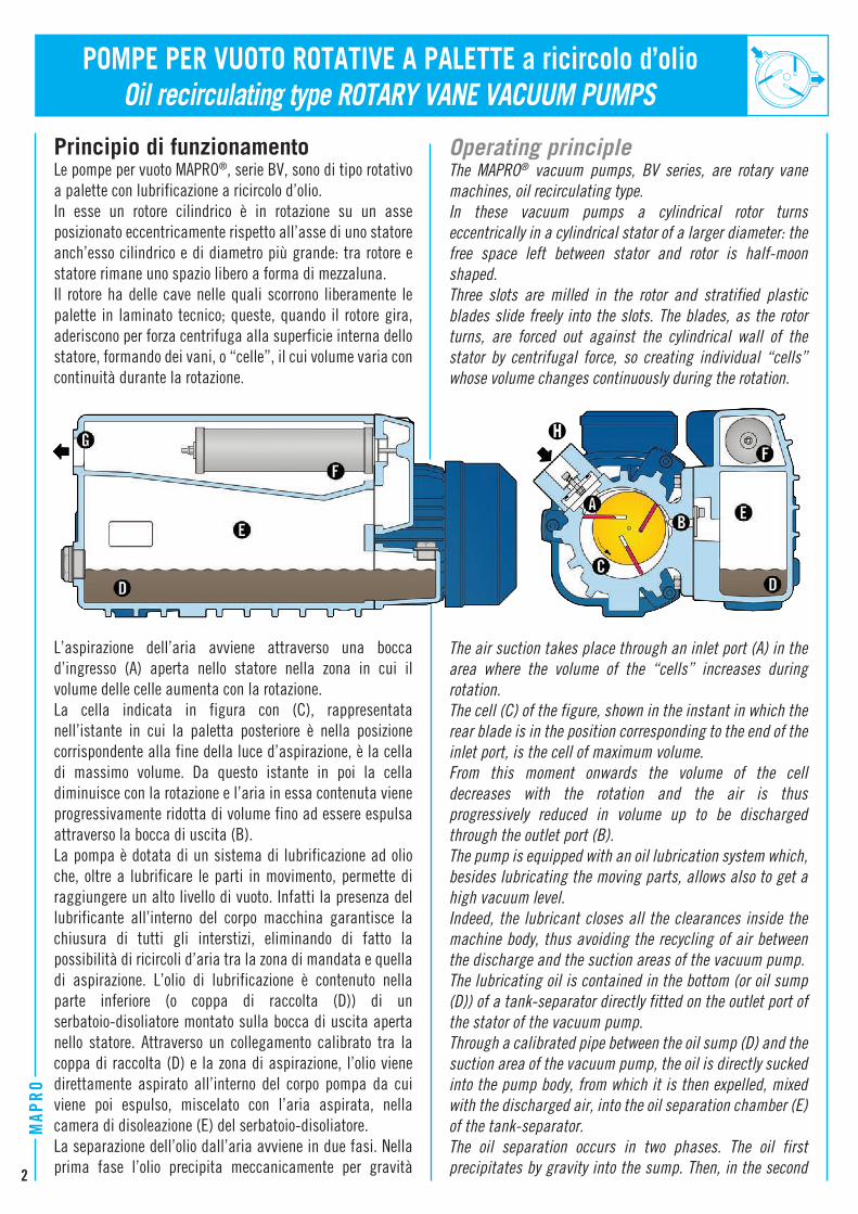
Principio di funzionamentoLe pompe per vuoto MAPRO®, serie BV, sono di tipo rotativo a palette con lubrificazione a ricircolo d’olio.In esse un rotore cilindrico è in rotazione su un asse posizionato eccentricamente rispetto all’asse di uno statore anch’esso cilindrico e di diametro più grande: tra rotore e statore rimane uno spazio libero a forma di mezzaluna.Il rotore ha delle cave nelle quali scorrono liberamente le palette in laminato tecnico; queste, quando il rotore gira, aderiscono per forza centrifuga alla superficie interna dello statore, formando dei vani, o “celle”, il cui volume varia con continuità durante la rotazione.
L’aspirazione dell’aria avviene attraverso una bocca d’ingresso (A) aperta nello statore nella zona in cui il volume delle celle aumenta con la rotazione. La cella indicata in figura con (C), rappresentata nell’istante in cui la paletta posteriore è nella posizione corrispondente alla fine della luce d’aspirazione, è la cella di massimo volume. Da questo istante in poi la cella diminuisce con la rotazione e l’aria in essa contenuta viene progressivamente ridotta di volume fino ad essere espulsa attraverso la bocca di uscita (B).La pompa è dotata di un sistema di lubrificazione ad olio che, oltre a lubrificare le parti in movimento, permette di raggiungere un alto livello di vuoto. Infatti la presenza del lubrificante all’interno del corpo macchina garantisce la chiusura di tutti gli interstizi, eliminando di fatto la possibilità di ricircoli d’aria tra la zona di mandata e quella di aspirazione. L’olio di lubrificazione è contenuto nella parte inferiore (o coppa di raccolta (D)) di un serbatoio-disoliatore montato sulla bocca di uscita aperta nello statore. Attraverso un collegamento calibrato tra la coppa di raccolta (D) e la zona di aspirazione, l’olio viene direttamente aspirato all’interno del corpo pompa da cui viene poi espulso, miscelato con l’aria aspirata, nella camera di disoleazione (E) del serbatoio-disoliatore.La separazione dell’olio dall’aria avviene in due fasi. Nella prima fase l’olio precipita meccanicamente per gravità
POMPE PER VUOTO ROTATIVE A PALETTE a ricircolo d’olio
Operating principle The MAPRO® vacuum pumps, BV series, are rotary vane machines, oil recirculating type.In these vacuum pumps a cylindrical rotor turns eccentrically in a cylindrical stator of a larger diameter: the free space left between stator and rotor is half-moon shaped.Three slots are milled in the rotor and stratified plastic blades slide freely into the slots. The blades, as the rotor turns, are forced out against the cylindrical wall of the stator by centrifugal force, so creating individual “cells” whose volume changes continuously during the rotation.
The air suction takes place through an inlet port (A) in the area where the volume of the “cells” increases during rotation. The cell (C) of the figure, shown in the instant in which the rear blade is in the position corresponding to the end of the inlet port, is the cell of maximum volume. From this moment onwards the volume of the cell decreases with the rotation and the air is thus progressively reduced in volume up to be discharged through the outlet port (B).The pump is equipped with an oil lubrication system which, besides lubricating the moving parts, allows also to get a high vacuum level. Indeed, the lubricant closes all the clearances inside the machine body, thus avoiding the recycling of air between the discharge and the suction areas of the vacuum pump.The lubricating oil is contained in the bottom (or oil sump (D)) of a tank-separator directly fitted on the outlet port of the stator of the vacuum pump. Through a calibrated pipe between the oil sump (D) and the suction area of the vacuum pump, the oil is directly sucked into the pump body, from which it is then expelled, mixed with the discharged air, into the oil separation chamber (E) of the tank-separator.The oil separation occurs in two phases. The oil first precipitates by gravity into the sump. Then, in the second
tornando a depositarsi nella coppa di raccolta. Nella seconda fase le particelle oleose residue, più piccole e più calde, vengono raffreddate nel loro passaggio attraverso la camera di disoleazione e trattenute nella cartuccia filtrante (F) da cui poi colano per essere reintrodotte nel circuito di lubrificazione. L’aria, ormai filtrata, viene infine espulsa attraverso il foro di uscita (G).
Le pompe per vuoto a ricircolo d’olio sono sempre dotate di una valvola di non ritorno (H) per evitare risalite di olio nella linea di aspirazione, e quindi nel sistema utilizzatore del vuoto, qualora la pompa venga fermata con il sistema utilizzatore in depressione.
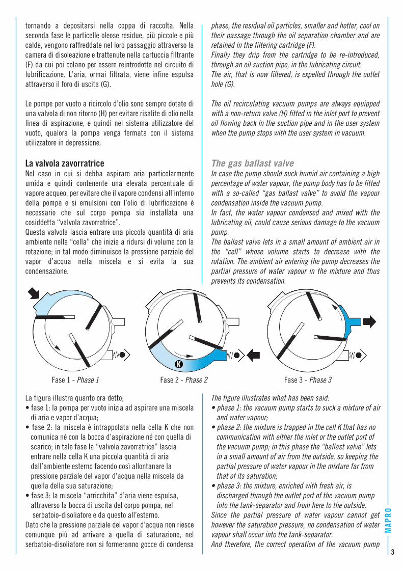
La valvola zavorratriceNel caso in cui si debba aspirare aria particolarmente umida e quindi contenente una elevata percentuale di vapore acqueo, per evitare che il vapore condensi all’interno della pompa e si emulsioni con l’olio di lubrificazione è necessario che sul corpo pompa sia installata una cosiddetta “valvola zavorratrice”.Questa valvola lascia entrare una piccola quantità di aria ambiente nella “cella” che inizia a ridursi di volume con la rotazione; in tal modo diminuisce la pressione parziale del vapor d’acqua nella miscela e si evita la sua condensazione.
La figura illustra quanto ora detto; • fase 1: la pompa per vuoto inizia ad aspirare una miscela di aria e vapor d’acqua;• fase 2: la miscela è intrappolata nella cella K che non comunica né con la bocca d’aspirazione né con quella di scarico; in tale fase la “valvola zavorratrice” lascia entrare nella cella K una piccola quantità di aria dall’ambiente esterno facendo così allontanare la pressione parziale del vapor d’acqua nella miscela da quella della sua saturazione;• fase 3: la miscela “arricchita” d’aria viene espulsa, attraverso la bocca di uscita del corpo pompa, nel serbatoio-disoliatore e da questo all’esterno.Dato che la pressione parziale del vapor d’acqua non riesce comunque più ad arrivare a quella di saturazione, nel serbatoio-disoliatore non si formeranno gocce di condensa
phase, the residual oil particles, smaller and hotter, cool on their passage through the oil separation chamber and are retained in the filtering cartridge (F). Finally they drip from the cartridge to be re-introduced, through an oil suction pipe, in the lubricating circuit. The air, that is now filtered, is expelled through the outlet hole (G).
The oil recirculating vacuum pumps are always equipped with a non-return valve (H) fitted in the inlet port to prevent oil flowing back in the suction pipe and in the user system when the pump stops with the user system in vacuum.
The gas ballast valveIn case the pump should suck humid air containing a high percentage of water vapour, the pump body has to be fitted with a so-called “gas ballast valve” to avoid the vapour condensation inside the vacuum pump. In fact, the water vapour condensed and mixed with the lubricating oil, could cause serious damage to the vacuum pump. The ballast valve lets in a small amount of ambient air in the “cell” whose volume starts to decrease with the rotation. The ambient air entering the pump decreases the partial pressure of water vapour in the mixture and thus prevents its condensation.
The figure illustrates what has been said:• phase 1: the vacuum pump starts to suck a mixture of air and water vapour;• phase 2: the mixture is trapped in the cell K that has no communication with either the inlet or the outlet port of the vacuum pump; in this phase the “ballast valve” lets in a small amount of air from the outside, so keeping the partial pressure of water vapour in the mixture far from that of its saturation;• phase 3: the mixture, enriched with fresh air, is discharged through the outlet port of the vacuum pump into the tank-separator and from here to the outside.Since the partial pressure of water vapour cannot get however the saturation pressure, no condensation of water vapour shall occur into the tank-separator.And therefore, the correct operation of the vacuum pump
Fase 1 - Phase 1 Fase 2 - Phase 2 Fase 3 - Phase 3
4
MAP
ROche, miscelandosi con l’olio di lubrificazione, potrebbero compromettere il buon funzionamento della pompa per vuoto.Avvertenza: prima di iniziare ad aspirare aria contenente vapore acqueo è necessario che la pompa per vuoto sia già calda. Occorre quindi farla funzionare preliminarmente, per alcuni minuti, a bocca d’aspirazione chiusa. La temperatura della miscela aria-vapore deve essere, inoltre, la più bassa possibile.
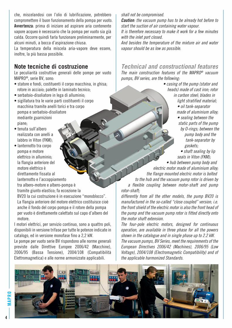
Note tecniche di costruzione Le peculiarità costruttive generali delle pompe per vuoto MAPRO®, serie BV, sono:• statore e fondi, costituenti il corpo macchina, in ghisa; rotore in acciaio; palette in laminato tecnico;• serbatoio-disoliatore in lega di alluminio;• sigillatura tra le varie parti costituenti il corpo macchina tramite anelli torici e tra corpo pompa e serbatoio-disoliatore mediante guarnizioni piane;• tenuta sull’albero realizzata con anelli a labbro in Viton (FKM);• lanternotto tra corpo pompa e motore elettrico in alluminio; la flangia anteriore del motore elettrico è direttamente fissata al lanternotto e l’accoppiamento tra albero-motore e albero-pompa è tramite giunto elastico; fa eccezione la BV20 la cui costruzione è in esecuzione “monoblocco”. La flangia anteriore del motore elettrico costituisce cioè anche il fondo del corpo pompa e il rotore della pompa per vuoto è direttamente calettato sul capo d’albero del motore.I motori elettrici, per servizio continuo, sono a quattro poli, disponibili in versione trifase per tutte le potenze indicate in catalogo, ed in versione monofase fino a 2,2 kW.Le pompe per vuoto serie BV rispondono alle norme generali previste dalle Direttive Europee 2006/42 (Macchine), 2006/95 (Bassa Tensione), 2004/108 (Compatibilità Elettromagnetica) e alle norme armonizzate applicabili.
shall not be compromised. Caution: the vacuum pump has to be already hot before to start the suction of air containing water vapour. It is therefore necessary to make it work for a few minutes with the inlet port closed. And besides the temperature of the mixture air and water vapour should be as low as possible.
Technical and constructional featuresThe main construction features of the MAPRO® vacuum pumps, BV series, are the following: • casing of the pump (stator and heads) made of cast iron; rotor in carbon steel; blades in light stratified material; • oil tank-separator made of aluminium alloy; • sealing between the static parts of the pump by O-rings; between the pump body and the tank-separator by gaskets; • shaft sealing by lip seals in Viton (FKM); • hub between pump body and electric motor made of aluminium alloy; the flange mounted electric motor is bolted to the hub and the vacuum pump rotor is driven by a flexible coupling between motor-shaft and pump rotor-shaft;differently from all the other models, the pump BV20 is manufactured in the so-called “close coupled” version; i.e. the front shield of the electric motor is also the front head of the pump and the vacuum pump rotor is fitted directly onto the motor shaft extension.The four-pole electric motors, designed for continuous operation, are available in three phase for all the powers shown in the catalogue and in single phase up to 2.2 kW.The vacuum pumps, BV Series, meet the requirements of the European Directives 2006/42 (Machines), 2006/95 (Low Voltage), 2004/108 (Electromagnetic Compatibility) and of the applicable harmonized Standards.
Vantaggi I maggiori vantaggi nell’utilizzo delle pompe per vuoto a ricircolo d’olio MAPRO® sono: • massima semplicità di installazione;• manutenzione semplice ed economica;• massima silenziosità;• rendimento volumetrico elevato e invariabile nel tempo;• assenza di pulsazioni nel flusso aspirato;• assenza di vibrazioni;• versatilità di impiego;• elevata compatibilità al vapore acqueo con valvola zavorratrice installata.
Applicazioni più comuni Tra i settori in cui possono essere impiegate le pompe per vuoto a ricircolo d’olio MAPRO® ricordiamo:• il confezionamento sotto vuoto • l’industria alimentare • gli impianti per vuoto centralizzato • la filtrazione sotto vuoto • la formatura della plastica • l’industria per la lavorazione del legno • la manipolazione con ventose • l’industria dell’imbottigliamento • i sistemi di insaccamento • l’industria della grafica • l’industria farmaceutica • l’industria conciaria.
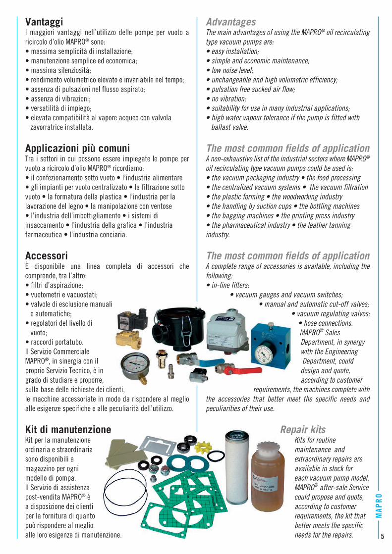
AccessoriÈ disponibile una linea completa di accessori che comprende, tra l’altro:• filtri d’aspirazione;• vuotometri e vacuostati;• valvole di esclusione manuali e automatiche;• regolatori del livello di vuoto;• raccordi portatubo.Il Servizio Commerciale MAPRO®, in sinergia con il proprio Servizio Tecnico, è in grado di studiare e proporre, sulla base delle richieste dei clienti, le macchine accessoriate in modo da rispondere al meglio alle esigenze specifiche e alle peculiarità dell’utilizzo.
Kit di manutenzioneKit per la manutenzione ordinaria e straordinaria sono disponibili a magazzino per ogni modello di pompa.Il Servizio di assistenza post-vendita MAPRO® è a disposizione dei clienti per la fornitura di quanto può rispondere al meglio alle loro esigenze di manutenzione.
AdvantagesThe main advantages of using the MAPRO® oil recirculating type vacuum pumps are:• easy installation;• simple and economic maintenance;• low noise level;• unchangeable and high volumetric efficiency;• pulsation free sucked air flow;• no vibration;• suitability for use in many industrial applications;• high water vapour tolerance if the pump is fitted with ballast valve.
The most common fields of applicationA non-exhaustive list of the industrial sectors where MAPRO® oil recirculating type vacuum pumps could be used is:• the vacuum packaging industry • the food processing • the centralized vacuum systems • the vacuum filtration • the plastic forming • the woodworking industry • the handling by suction cups • the bottling machines • the bagging machines • the printing press industry • the pharmaceutical industry • the leather tanning industry.
The most common fields of applicationA complete range of accessories is available, including the following:• in-line filters; • vacuum gauges and vacuum switches; • manual and automatic cut-off valves; • vacuum regulating valves; • hose connections. MAPRO® Sales Department, in synergy with the Engineering Department, could design and quote, according to customer requirements, the machines complete with the accessories that better meet the specific needs and peculiarities of their use.
Repair kits Kits for routine maintenance and extraordinary repairs are available in stock for each vacuum pump model. MAPRO® after-sale Service could propose and quote, according to customer requirements, the kit that better meets the specific needs for the repairs. 5
6
MAP
RO
BV 20
0,1
1
10
0,1 1 10 100 1000
m³/h
mbar ass. - mbar abs. 0,5
20
3040
86
4
2
0,10,1 1 10 100 1000
m³/h
mbar ass. - mbar abs. 0,5
1
10
20
3040
86
4
2
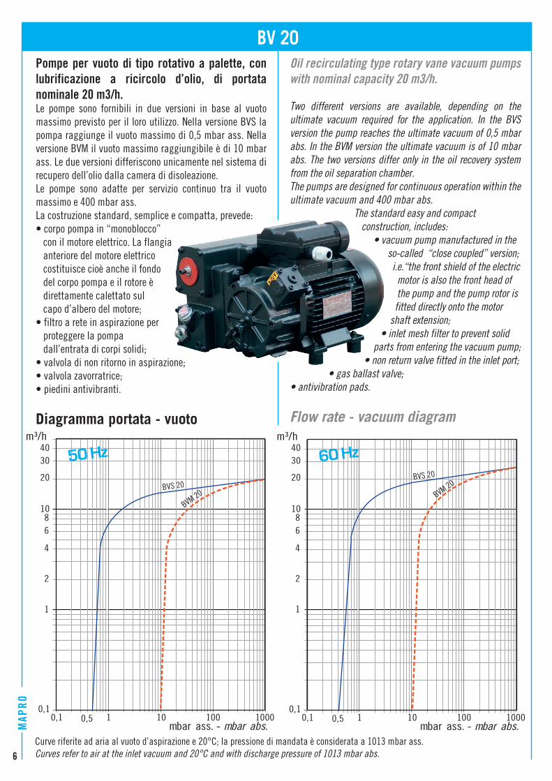
Curve riferite ad aria al vuoto d’aspirazione e 20°C; la pressione di mandata è considerata a 1013 mbar ass.Curves refer to air at the inlet vacuum and 20°C and with discharge pressure of 1013 mbar abs.
Pompe per vuoto di tipo rotativo a palette, con lubrificazione a ricircolo d’olio, di portata nominale 20 m3/h.Le pompe sono fornibili in due versioni in base al vuoto massimo previsto per il loro utilizzo. Nella versione BVS la pompa raggiunge il vuoto massimo di 0,5 mbar ass. Nella versione BVM il vuoto massimo raggiungibile è di 10 mbar ass. Le due versioni differiscono unicamente nel sistema di recupero dell’olio dalla camera di disoleazione.Le pompe sono adatte per servizio continuo tra il vuoto massimo e 400 mbar ass.La costruzione standard, semplice e compatta, prevede:• corpo pompa in “monoblocco” con il motore elettrico. La flangia anteriore del motore elettrico costituisce cioè anche il fondo del corpo pompa e il rotore è direttamente calettato sul capo d’albero del motore;• filtro a rete in aspirazione per proteggere la pompa dall’entrata di corpi solidi;• valvola di non ritorno in aspirazione;• valvola zavorratrice;• piedini antivibranti.
Diagramma portata - vuoto
Oil recirculating type rotary vane vacuum pumps with nominal capacity 20 m3/h.
Two different versions are available, depending on the ultimate vacuum required for the application. In the BVS version the pump reaches the ultimate vacuum of 0,5 mbar abs. In the BVM version the ultimate vacuum is of 10 mbar abs. The two versions differ only in the oil recovery system from the oil separation chamber.The pumps are designed for continuous operation within the ultimate vacuum and 400 mbar abs. The standard easy and compact construction, includes: • vacuum pump manufactured in the so-called “close coupled” version; i.e.“the front shield of the electric motor is also the front head of the pump and the pump rotor is fitted directly onto the motor shaft extension; • inlet mesh filter to prevent solid parts from entering the vacuum pump; • non return valve fitted in the inlet port; • gas ballast valve;• antivibration pads.
Flow rate - vacuum diagram
50 Hz 60 Hz
BVS 20
BVM 20 BVM 20BVS 20
7
Nominal capacityPortata nominale
Ultimate vacuumVuoto massimo
Electric motor: VoltageMotore elettrico: Tensione
Electric motor: PowerMotore elettrico: Potenza
Velocità di rotazioneSpeed of rotationRumorosità a 1m. (*)Noise level at 1m. (*)
50 Hz[dB(A)] 64 ± 2
65 ± 2
[kg]
60 Hz
22
Quantità olioOil capacity [l] 0,5
BVS20 BVM202024
0,5 10
PesoWeight
50 Hz[kW]
3-ph
[rpm] 50 Hz60 Hz
50 Hz60 Hz
[m3/h]
1450
50 1000
1740
60 Hz
[mbar ass.] - [mbar abs.][Pa ass.] - [Pa abs.]
0,750,9
230/400 V (50 Hz) - 265/460 V (60 Hz)230 V (50 Hz) - 265 V (60 Hz)1-ph
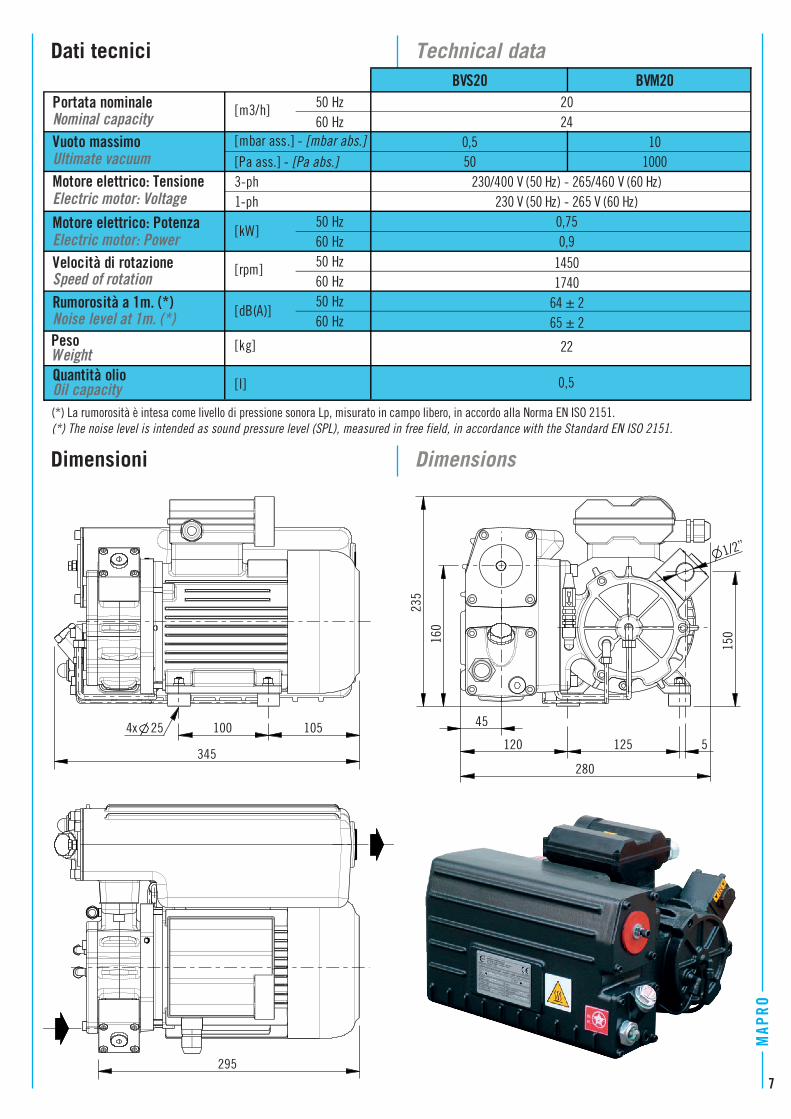
(*) La rumorosità è intesa come livello di pressione sonora Lp, misurato in campo libero, in accordo alla Norma EN ISO 2151.(*) The noise level is intended as sound pressure level (SPL), measured in free field, in accordance with the Standard EN ISO 2151.
4x 25 100 105
235
280
125345
120
150
1/2”
295
45
160
5
8
MAP
RO
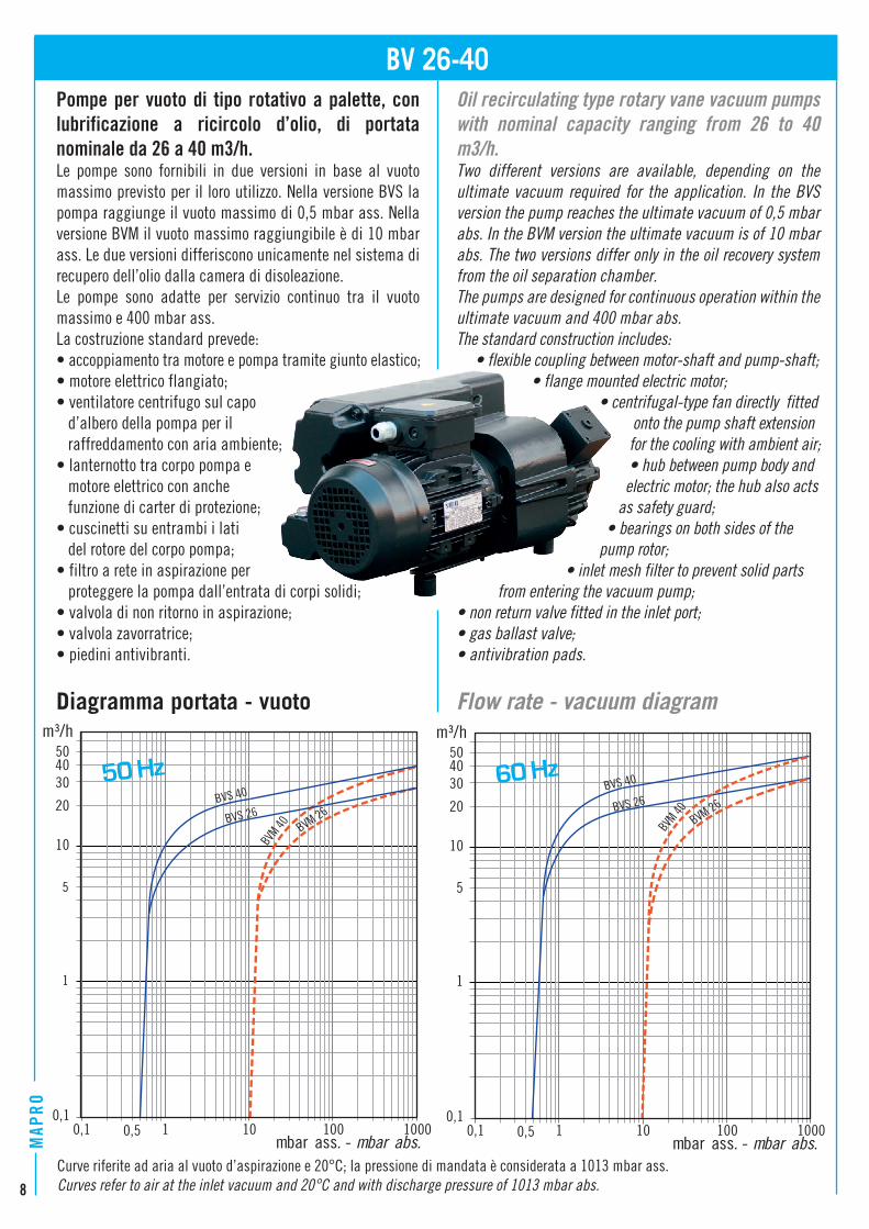
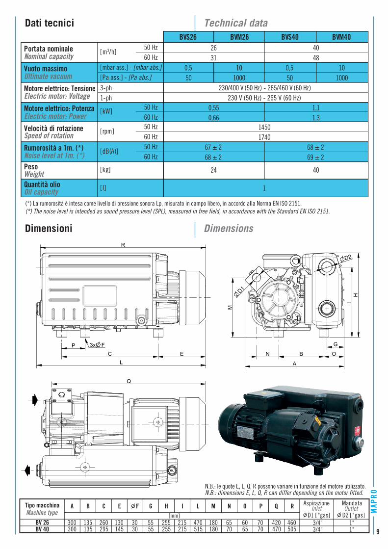
Pompe per vuoto di tipo rotativo a palette, con lubrificazione a ricircolo d’olio, di portata nominale da 26 a 40 m3/h.Le pompe sono fornibili in due versioni in base al vuoto massimo previsto per il loro utilizzo. Nella versione BVS la pompa raggiunge il vuoto massimo di 0,5 mbar ass. Nella versione BVM il vuoto massimo raggiungibile è di 10 mbar ass. Le due versioni differiscono unicamente nel sistema di recupero dell’olio dalla camera di disoleazione.Le pompe sono adatte per servizio continuo tra il vuoto massimo e 400 mbar ass.La costruzione standard prevede:• accoppiamento tra motore e pompa tramite giunto elastico;• motore elettrico flangiato;• ventilatore centrifugo sul capo d’albero della pompa per il raffreddamento con aria ambiente;• lanternotto tra corpo pompa e motore elettrico con anche funzione di carter di protezione;• cuscinetti su entrambi i lati del rotore del corpo pompa;• filtro a rete in aspirazione per proteggere la pompa dall’entrata di corpi solidi;• valvola di non ritorno in aspirazione;• valvola zavorratrice;• piedini antivibranti.
Diagramma portata - vuoto
Oil recirculating type rotary vane vacuum pumps with nominal capacity ranging from 26 to 40 m3/h.Two different versions are available, depending on the ultimate vacuum required for the application. In the BVS version the pump reaches the ultimate vacuum of 0,5 mbar abs. In the BVM version the ultimate vacuum is of 10 mbar abs. The two versions differ only in the oil recovery system from the oil separation chamber.The pumps are designed for continuous operation within the ultimate vacuum and 400 mbar abs.The standard construction includes: • flexible coupling between motor-shaft and pump-shaft; • flange mounted electric motor; • centrifugal-type fan directly fitted onto the pump shaft extension for the cooling with ambient air; • hub between pump body and electric motor; the hub also acts as safety guard; • bearings on both sides of the pump rotor; • inlet mesh filter to prevent solid parts from entering the vacuum pump;• non return valve fitted in the inlet port;• gas ballast valve;• antivibration pads.
Flow rate - vacuum diagram
BV 26-40
0,1
1
10
0,1 1 10 100 1000
m³/h
0,5mbar ass. - mbar abs.
5
20
30
5040
0,10,1 1 10 100 1000
m³/h
0,5mbar ass. - mbar abs.
1
10
5
20
30
5040
Curve riferite ad aria al vuoto d’aspirazione e 20°C; la pressione di mandata è considerata a 1013 mbar ass.Curves refer to air at the inlet vacuum and 20°C and with discharge pressure of 1013 mbar abs.
BVS 40
BVM 26BVS 26
BVM 40
BVS 40
BVM 26BVS 26
BVM 40
50 Hz 60 Hz
9
Nominal capacityPortata nominale
Ultimate vacuumVuoto massimo
Electric motor: VoltageMotore elettrico: Tensione
Motore elettrico: PotenzaElectric motor: Power
Speed of rotationVelocità di rotazione
230 V (50 Hz) - 265 V (60 Hz)
0,5 101000
230/400 V (50 Hz) - 265/460 V (60 Hz)
2631
4048
68 ± 269 ± 2
40
1
0,55 1,10,66
[mbar ass.] - [mbar abs.][Pa ass.] - [Pa abs.] 50 1000 50
1-ph
1,3
0,5 10
[kg]
[rpm]50 Hz60 Hz
[dB(A)] 50 Hz60 Hz
50 Hz60 Hz
[m3/h]
60 Hz1450
Noise level at 1m. (*)Rumorosità a 1m. (*) 67 ± 2
BVS40 BVM40BVM26BVS26
1740
PesoWeight
68 ± 2
24
Quantità olioOil capacity [l]
50 Hz[kW]
3-ph
3x F
LEC
P
R
B
A
N O
G
H
D1
D2
M
Q
Tipo macchina Aspirazione
Machine typeInlet
D1 [ "gas]P Q
[mm]
H I L M N OA B C E F G R
BV 26BV 40
300 135 260 130 30 55 255 215 470 180 65 60 70 420 460300 135 295 145 30 55 255 215 515 180 70 65 70 470 505
3/4" 1"3/4" 1"
MandataOutlet
D2 [ "gas]
(*) La rumorosità è intesa come livello di pressione sonora Lp, misurato in campo libero, in accordo alla Norma EN ISO 2151.(*) The noise level is intended as sound pressure level (SPL), measured in free field, in accordance with the Standard EN ISO 2151.
N.B.: le quote E, L, Q, R possono variare in funzione del motore utilizzato.N.B.: dimensions E, L, Q, R can differ depending on the motor fitted.
I
10
MAP
RO
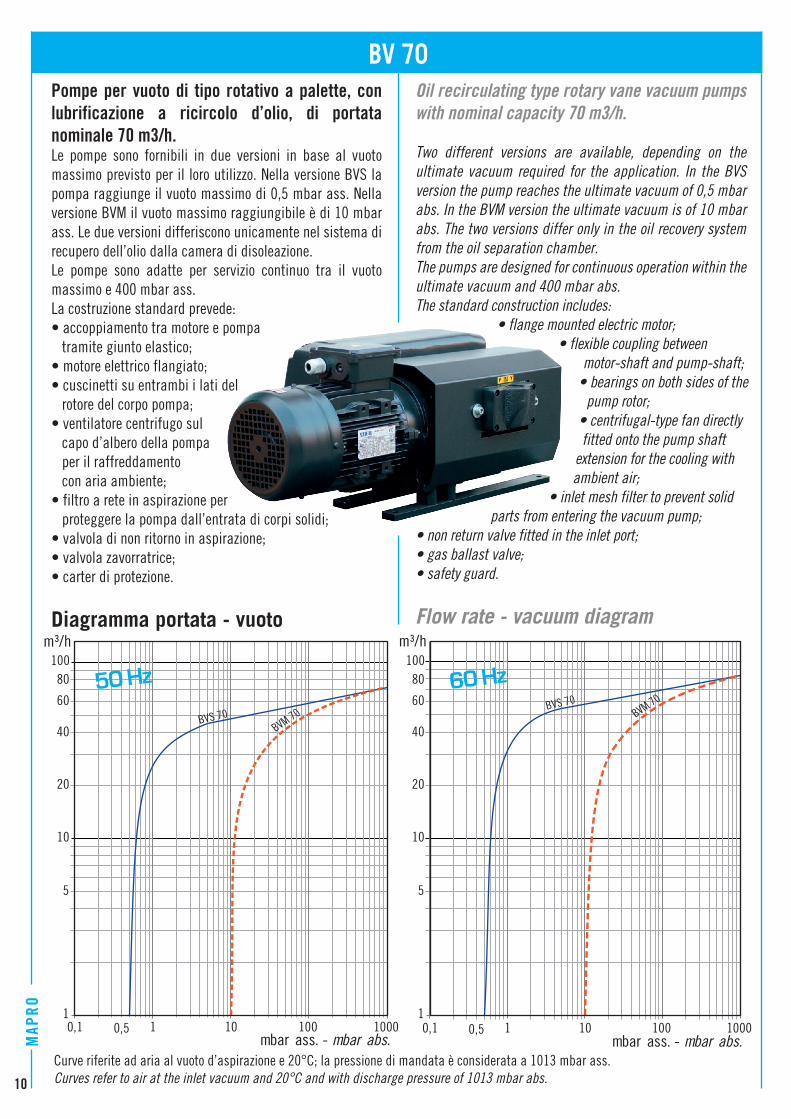
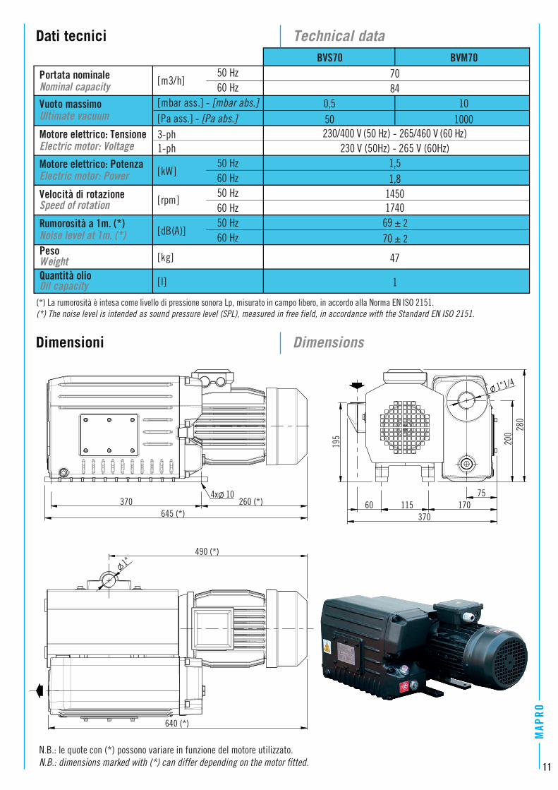
Pompe per vuoto di tipo rotativo a palette, con lubrificazione a ricircolo d’olio, di portata nominale 70 m3/h.Le pompe sono fornibili in due versioni in base al vuoto massimo previsto per il loro utilizzo. Nella versione BVS la pompa raggiunge il vuoto massimo di 0,5 mbar ass. Nella versione BVM il vuoto massimo raggiungibile è di 10 mbar ass. Le due versioni differiscono unicamente nel sistema di recupero dell’olio dalla camera di disoleazione. Le pompe sono adatte per servizio continuo tra il vuoto massimo e 400 mbar ass.La costruzione standard prevede:• accoppiamento tra motore e pompa tramite giunto elastico;• motore elettrico flangiato;• cuscinetti su entrambi i lati del rotore del corpo pompa;• ventilatore centrifugo sul capo d’albero della pompa per il raffreddamento con aria ambiente;• filtro a rete in aspirazione per proteggere la pompa dall’entrata di corpi solidi;• valvola di non ritorno in aspirazione;• valvola zavorratrice;• carter di protezione.
Diagramma portata - vuoto
Oil recirculating type rotary vane vacuum pumps with nominal capacity 70 m3/h.
Two different versions are available, depending on the ultimate vacuum required for the application. In the BVS version the pump reaches the ultimate vacuum of 0,5 mbar abs. In the BVM version the ultimate vacuum is of 10 mbar abs. The two versions differ only in the oil recovery system from the oil separation chamber.The pumps are designed for continuous operation within the ultimate vacuum and 400 mbar abs.The standard construction includes: • flange mounted electric motor; • flexible coupling between motor-shaft and pump-shaft; • bearings on both sides of the pump rotor; • centrifugal-type fan directly fitted onto the pump shaft extension for the cooling with ambient air; • inlet mesh filter to prevent solid parts from entering the vacuum pump;• non return valve fitted in the inlet port;• gas ballast valve;• safety guard.
Flow rate - vacuum diagram
BV 70
1
10
100
0,1 1 10 100 1000
m³/h
0,5mbar ass. - mbar abs.
20
40
60
80
5
0,1 1 10 100 1000
m³/h
0,5mbar ass. - mbar abs.
1
10
100
20
40
60
80
5
Curve riferite ad aria al vuoto d’aspirazione e 20°C; la pressione di mandata è considerata a 1013 mbar ass.Curves refer to air at the inlet vacuum and 20°C and with discharge pressure of 1013 mbar abs.
BVS 70BVM 70
BVS 70BVM 70
50 Hz 60 Hz
11
Nominal capacityPortata nominale
Ultimate vacuumVuoto massimo
Electric motor: VoltageMotore elettrico: Tensione
Electric motor: PowerMotore elettrico: Potenza
Speed of rotationVelocità di rotazione
Rumorosità a 1m. (*) 50 Hz[dB(A)] Noise level at 1m. (*)
69 ± 2
70 ± 2
[kg]
60 Hz
47
Quantità olioOil capacity [l] 1
BVS70 BVM707084
0,5 10
PesoWeight
50 Hz[kW]
3-ph1-ph
[rpm]50 Hz60 Hz
50 Hz60 Hz
[m3/h]
1450
50 1000
1740
60 Hz
[mbar ass.] - [mbar abs.][Pa ass.] - [Pa abs.]
1,51,8
230 V (50Hz) - 265 V (60Hz)230/400 V (50 Hz) - 265/460 V (60 Hz)
115 170
490 (*)
7520
0
1"1/4
1"
280
195
60370
640 (*)
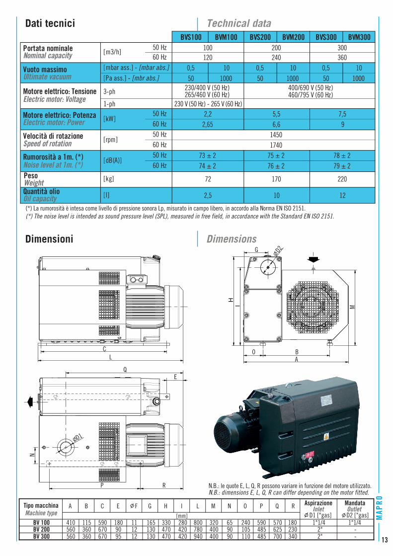
Dati tecnici
Dimensioni
Technical data
Dimensions
(*) La rumorosità è intesa come livello di pressione sonora Lp, misurato in campo libero, in accordo alla Norma EN ISO 2151.(*) The noise level is intended as sound pressure level (SPL), measured in free field, in accordance with the Standard EN ISO 2151.
4x 10370 260 (*)
645 (*)
N.B.: le quote con (*) possono variare in funzione del motore utilizzato.N.B.: dimensions marked with (*) can differ depending on the motor fitted.
12
MAP
RO
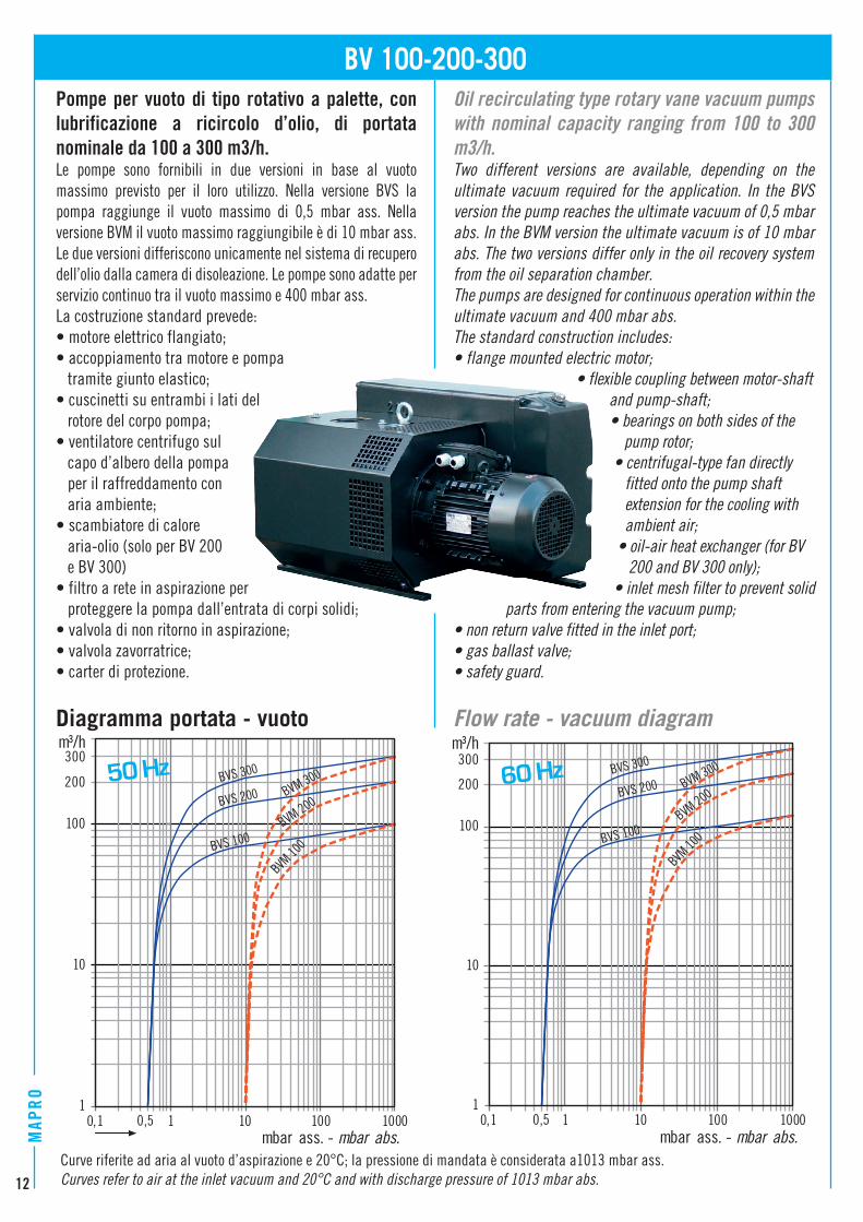
Pompe per vuoto di tipo rotativo a palette, con lubrificazione a ricircolo d’olio, di portata nominale da 100 a 300 m3/h.Le pompe sono fornibili in due versioni in base al vuoto massimo previsto per il loro utilizzo. Nella versione BVS la pompa raggiunge il vuoto massimo di 0,5 mbar ass. Nella versione BVM il vuoto massimo raggiungibile è di 10 mbar ass. Le due versioni differiscono unicamente nel sistema di recupero dell’olio dalla camera di disoleazione. Le pompe sono adatte per servizio continuo tra il vuoto massimo e 400 mbar ass.La costruzione standard prevede:• motore elettrico flangiato;• accoppiamento tra motore e pompa tramite giunto elastico;• cuscinetti su entrambi i lati del rotore del corpo pompa;• ventilatore centrifugo sul capo d’albero della pompa per il raffreddamento con aria ambiente;• scambiatore di calore aria-olio (solo per BV 200 e BV 300)• filtro a rete in aspirazione per proteggere la pompa dall’entrata di corpi solidi;• valvola di non ritorno in aspirazione;• valvola zavorratrice;• carter di protezione.
Diagramma portata - vuoto
Oil recirculating type rotary vane vacuum pumps with nominal capacity ranging from 100 to 300 m3/h.Two different versions are available, depending on the ultimate vacuum required for the application. In the BVS version the pump reaches the ultimate vacuum of 0,5 mbar abs. In the BVM version the ultimate vacuum is of 10 mbar abs. The two versions differ only in the oil recovery system from the oil separation chamber.The pumps are designed for continuous operation within the ultimate vacuum and 400 mbar abs.The standard construction includes:• flange mounted electric motor; • flexible coupling between motor-shaft and pump-shaft; • bearings on both sides of the pump rotor; • centrifugal-type fan directly fitted onto the pump shaft extension for the cooling with ambient air; • oil-air heat exchanger (for BV 200 and BV 300 only); • inlet mesh filter to prevent solid parts from entering the vacuum pump;• non return valve fitted in the inlet port;• gas ballast valve;• safety guard.
Flow rate - vacuum diagram
BV 100-200-300
1
10
100
0,1 1 10 100 1000
m³/h
mbar ass. - mbar abs. 0,5
200
1
10
100
0,1 1 10 100 1000
m³/h
0,5
200
300
mbar ass. - mbar abs.
BVS 300
BVS 200
BVS 100
BVM 300
BVM 200
300
Curve riferite ad aria al vuoto d’aspirazione e 20°C; la pressione di mandata è considerata a1013 mbar ass.Curves refer to air at the inlet vacuum and 20°C and with discharge pressure of 1013 mbar abs.
BVM 10
0
BVS 300
BVS 200
BVS 100
BVM 300
BVM 200
BVM 10
0
50 Hz 60 Hz
13
Nominal capacityPortata nominale
Ultimate vacuumVuoto massimo
Electric motor: VoltageMotore elettrico: Tensione
Speed of rotationVelocità di rotazione
36010 0,5 10[mbar ass.] - [mbar abs.]
[Pa ass.] - [mbr abs.] 1000 50 1000 50
2,2 5,5 7,5
230/400 V (50 Hz)265/460 V (60 Hz)
400/690 V (50 Hz)460/795 V (60 Hz)
72 170 220[kg]
[rpm]50 Hz60 Hz
[dB(A)] 50 Hz60 Hz
50
50 Hz60 Hz
[m3/h] 100BVS300BVM200
1450
BVS200BVM100 BVS100
PesoWeight
50 Hz[kW]
2,65 6,6 9
200
3-ph
1-ph
BVM300
120 240
74 ± 2 76 ± 2 79 ± 2
174073 ± 2 75 ± 2 78 ± 2
Oil capacityQuantità olio [l] 12
Rumorosità a 1m. (*)Noise level at 1m. (*)
300
0,5
2,5 10
10
60 Hz
10000,5
230 V (50 Hz) - 265 V (60 Hz)
Electric motor: PowerMotore elettrico: Potenza
Tipo macchina Aspirazione
Machine type InletD1 ["gas]
410 115 590 180 11 165 330 280 800 320 65 240 590 570 180560 360 670 90 12 130 470 420 780 400 90 105 485 625 230560 360 670 95 12 130 470 420 940 400 90 110 485 700 340
P Q[mm]
H I L M N OA B C E F G R
BV 100BV 200BV 300
MandataOutletD2 ["gas]
1"1/4 1"1/42" -2" -
(*) La rumorosità è intesa come livello di pressione sonora Lp, misurato in campo libero, in accordo alla Norma EN ISO 2151.(*) The noise level is intended as sound pressure level (SPL), measured in free field, in accordance with the Standard EN ISO 2151.
N.B.: le quote E, L, Q, R possono variare in funzione del motore utilizzato.N.B.: dimensions E, L, Q, R can differ depending on the motor fitted.
BA
H
LM
C
Q
D1
P
N
O
G
I
D2
E
R
14
MAP
RO
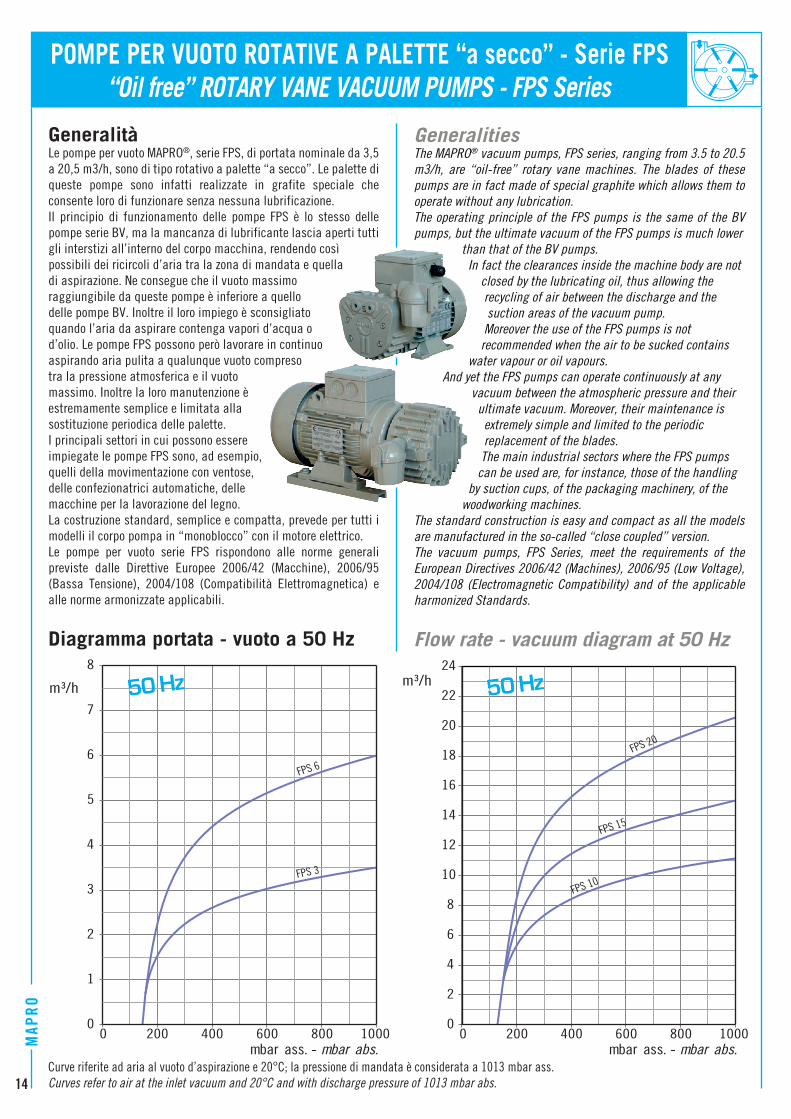
“Oil free” ROTARY VANE VACUUM PUMPS - FPS Series Generalità
Le pompe per vuoto MAPRO®, serie FPS, di portata nominale da 3,5 a 20,5 m3/h, sono di tipo rotativo a palette “a secco”. Le palette di queste pompe sono infatti realizzate in grafite speciale che consente loro di funzionare senza nessuna lubrificazione. Il principio di funzionamento delle pompe FPS è lo stesso delle pompe serie BV, ma la mancanza di lubrificante lascia aperti tutti gli interstizi all’interno del corpo macchina, rendendo cosìpossibili dei ricircoli d’aria tra la zona di mandata e quella di aspirazione. Ne consegue che il vuoto massimo raggiungibile da queste pompe è inferiore a quello delle pompe BV. Inoltre il loro impiego è sconsigliato quando l’aria da aspirare contenga vapori d’acqua o d’olio. Le pompe FPS possono però lavorare in continuo aspirando aria pulita a qualunque vuoto compreso tra la pressione atmosferica e il vuoto massimo. Inoltre la loro manutenzione è estremamente semplice e limitata alla sostituzione periodica delle palette. I principali settori in cui possono essere impiegate le pompe FPS sono, ad esempio, quelli della movimentazione con ventose, delle confezionatrici automatiche, delle macchine per la lavorazione del legno. La costruzione standard, semplice e compatta, prevede per tutti i modelli il corpo pompa in “monoblocco” con il motore elettrico. Le pompe per vuoto serie FPS rispondono alle norme generali previste dalle Direttive Europee 2006/42 (Macchine), 2006/95 (Bassa Tensione), 2004/108 (Compatibilità Elettromagnetica) e alle norme armonizzate applicabili.
Diagramma portata - vuoto a 50 Hz
POMPE PER VUOTO ROTATIVE A PALETTE “a secco” - Serie FPS
Generalities The MAPRO® vacuum pumps, FPS series, ranging from 3.5 to 20.5 m3/h, are “oil-free” rotary vane machines. The blades of these pumps are in fact made of special graphite which allows them to operate without any lubrication.The operating principle of the FPS pumps is the same of the BV pumps, but the ultimate vacuum of the FPS pumps is much lower than that of the BV pumps. In fact the clearances inside the machine body are not closed by the lubricating oil, thus allowing the recycling of air between the discharge and the suction areas of the vacuum pump. Moreover the use of the FPS pumps is not recommended when the air to be sucked contains water vapour or oil vapours. And yet the FPS pumps can operate continuously at any vacuum between the atmospheric pressure and their ultimate vacuum. Moreover, their maintenance is extremely simple and limited to the periodic replacement of the blades. The main industrial sectors where the FPS pumps can be used are, for instance, those of the handling by suction cups, of the packaging machinery, of the woodworking machines. The standard construction is easy and compact as all the models are manufactured in the so-called “close coupled” version.The vacuum pumps, FPS Series, meet the requirements of the European Directives 2006/42 (Machines), 2006/95 (Low Voltage), 2004/108 (Electromagnetic Compatibility) and of the applicable harmonized Standards.
Flow rate - vacuum diagram at 50 Hz
0
2
4
6
8
10
12
14
16
18
20
22
24
0 200 400 600 800 1000
m³/h
mbar ass. - mbar abs.
0
1
2
3
4
5
6
7
8
0 200 400 600 800 1000
m³/h
mbar ass. - mbar abs.
50 Hz 50 Hz
Curve riferite ad aria al vuoto d’aspirazione e 20°C; la pressione di mandata è considerata a 1013 mbar ass.Curves refer to air at the inlet vacuum and 20°C and with discharge pressure of 1013 mbar abs.
FPS 6
FPS 3
FPS 20
FPS 15
FPS 10
15
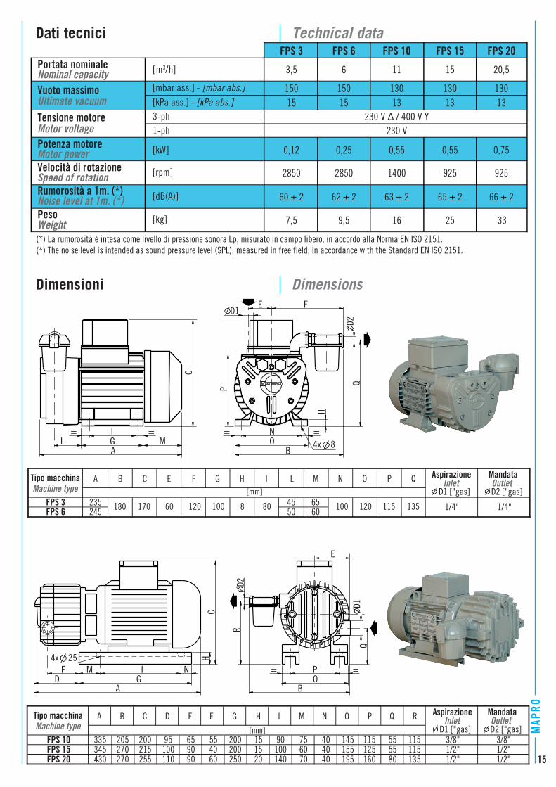
[mbar ass.] - [mbar abs.] Ultimate vacuum Vuoto massimo 150 150 130 130 130
[kPa ass.] - [kPa abs.] 15 15 13 13 13Tensione motoreMotor voltage
3-ph1-ph 230 V
Motor powerPotenza motore [kW] 0,12 0,25 0,55 0,55 0,75
Speed of rotationVelocità di rotazione [rpm] 2850 2850 1400 925 925
Noise level at 1m. (*) Rumorosità a 1m. (*) [dB(A)] 60 ± 2 62 ± 2
FPS 3 FPS 6 FPS 10 FPS 15 FPS 20
Nominal capacity Portata nominale [m3/h] 3,5 6 11 15 20,5
WeightPeso [kg]
(*) La rumorosità è intesa come livello di pressione sonora Lp, misurato in campo libero, in accordo alla Norma EN ISO 2151.(*) The noise level is intended as sound pressure level (SPL), measured in free field, in accordance with the Standard EN ISO 2151.
Dati tecnici
Dimensioni
Technical data
Dimensions
66 ± 263 ± 2
7,5 9,5 25 33
65 ± 2
16
Tipo macchina Aspirazione
Machine type InletD1 ["gas]
335 205 200 95 65 55 200 15 90 75 40 145 115 55 115345 270 215 100 90 40 200 15 100 60 40 155 125 55 115430 270 255 110 90 60 250 20 140 70 40 195 160 80 135
P Q[mm]
G H I M N OA B C D E F R
FPS 10FPS 15FPS 20
MandataOutletD2 ["gas]
3/8" 3/8"1/2" 1/2"1/2" 1/2"
Tipo macchina Aspirazione
Machine type InletD1 ["gas]
235 180 170 60 120 100 8 80 45 65 100 120 135245 50 60
P Q[mm]
H I L M N OA B C E F G
FPS 3FPS 6
MandataOutletD2 ["gas]
1/4" 1/4"115
NG
AD
IMF4x 25
CH
BOP
E
QD1
D2R
C
MGA
LI
OB
N4x 8
P
HD1
FE
D2Q
= = = =
= =
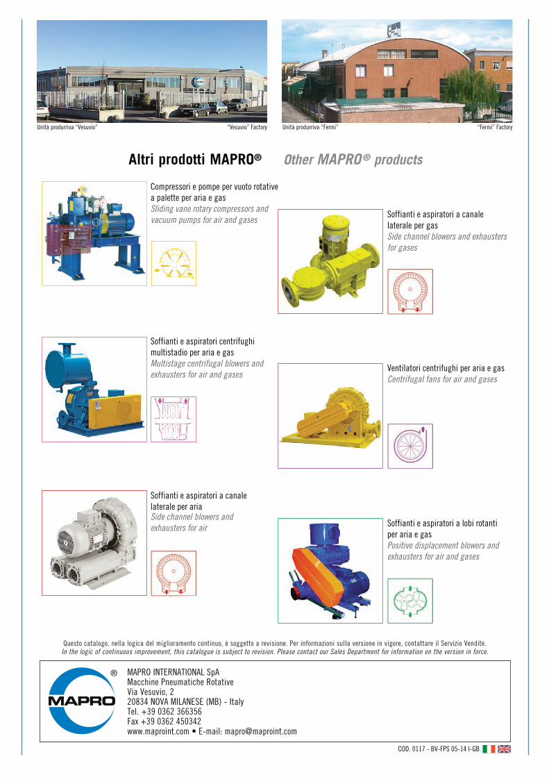
Compressori e pompe per vuoto rotativea palette per aria e gasSliding vane rotary compressors andvacuum pumps for air and gases
Soffianti e aspiratori a canalelaterale per gasSide channel blowers and exhaustersfor gases
Ventilatori centrifughi per aria e gasCentrifugal fans for air and gases
Soffianti e aspiratori a lobi rotantiper aria e gasPositive displacement blowers andexhausters for air and gases
Soffianti e aspiratori a canale laterale per ariaSide channel blowers and exhausters for air
Soffianti e aspiratori centrifughimultistadio per aria e gasMultistage centrifugal blowers andexhausters for air and gases
Unità produrriva “Vesuvio” “Vesuvio” Factory Unità produrriva “Fermi” “Fermi” Factory
MAPRO INTERNATIONAL SpAMacchine Pneumatiche RotativeVia Vesuvio, 220834 NOVA MILANESE (MB) - ItalyTel. +39 0362 366356Fax +39 0362 450342www.maproint.com • E-mail: [email protected]
COD. 0117 - BV-FPS 05-14 I-GB
Altri prodotti MAPRO® Other MAPRO® products
Questo catalogo, nella logica del miglioramento continuo, è soggetto a revisione. Per informazioni sulla versione in vigore, contattare il Servizio Vendite. In the logic of continuous improvement, this catalogue is subject to revision. Please contact our Sales Department for information on the version in force.