per lubrificare to lubricate mandrini …pdfs.findtheneedle.co.uk/121470-1313.pdf · constant basis...
TRANSCRIPT

PER LUBRIFICARE TO LUBRICATE MANDRINI SPINDLES ELETTROMANDRINI MOTOR SPINDLES VITI SENZA FINE BALL SCREWS INGRANAGGI GEARS
ILC SRL – VIA GARIBALDI, 149 – 21055 GORLA MINORE (VA) – ITALY PHONE ++39/0331/601697 FAX ++39/0331/365149 E-MAIL : [email protected]
ILC SRL – VIA GARIBALDI, 149 – 21055 GORLA MINORE (VA) – ITALY
PAGINA PAGE INDICE INDEX
2 Principio di funzionamento Principali applicazioni
Principle of air/oil lubrication Range of applications
3 Esempio applicazione per Elettromandrini Anti-friction bearings in spindles service as an example
8 Layout Layout
9 Principali elementi Main components
10 Funzionamento Operation
11 Unità con scatola di protezione Units with box
12 Unità senza scatola di protezione Units without box
14 Micropompa pneumatica di dosaggio Positive displacement metering pneumatic pump
13 Come ordinare un’unità con o senza scatola di protezione con serbatoio a gravità
How to order a unit with or without box with a gravity oil reservoir
16 Sottobase pompa per miscelazione aria-olio Pump base to mix air and oil
17 Sensore induttivo per controllo flusso lubrificante
Inductive sensor to monitor the lubricant
18 Blocco di controllo pressione aria principale Block to check main air
19 Blocco di controllo pressione minima dell’aria
Block to check air low pressure
20 Blocco di controllo minima e massima pressione d’aria
Block to check air low and high pressure
21 Pompa del vuoto Vacuum pump
23 Schema elettrico per le unità che sono consegnate senza il PLC
Electrical wiring for units produced without PLC
24 Serbatoio pressurizzato Pressurized reservoir
33 Come ordinare un’unità con il serbatoio pressurizzato
How to order a unit with a p essurized reservoir r
PHONE ++39/0331/601697 FAX ++39/0331/365149 E-MAIL : [email protected] - 1 -

ILC SRL – VIA GARIBALDI, 149 – 21055 GORLA MINORE (VA) – ITALY
1. PRINCIPIO DI FUNZIONAMENTO DEGLI
IMPIANTI ARIA-OLIO
2. PRINCIPLE OF AIR/OIL LUBRICATION
I gruppi d i micro- lubrif icazione ar ia/ol io basano i l loro princip io di funzionamento nel la scomposiz ione di una goccia d ’o l io o frazione che, inv iata a l l ’ interno di una tubazione flessibi le di p iccolo diametro, forma una pel l ico la o f i lm d ’o l io aderente a l la parete interna del la tubazione. Mediante i l medesimo f lusso d ’aria , i l lubrif icante è progressivamente inviato verso i l punto da lubrif icare. Dimensionando opportunamente la lunghezza del la tubazione (min imo 1 m) ed i l dosaggio del l ’o l io s i ott iene un inv io continuo di microgocce di lubrificante proiettate sul punto da lubrif icare che, una vo lta raggiunto, tratt iene l ’o l io lasciando fuoriuscire l iberamente i l f lusso d ’aria verso l ’esterno senza creare a lcun problema d ’ inquinamento per l ’ambiente. L ’effetto refrigerante del f lusso d ’aria che, o ltre a mantenere minima la temperatura del cuscinetto, genera una leggera sovrapressione che impedisce la penetrazione dal l ’esterno d ’eventual i impurità .
Air/oil lubrication is based on the principle that a dropof liquid is split by airflow, dispersed in streaks and transported in the direction of the airflow.
In practice, the drop is transported along the inner walls of a narrow tube in the direction of the lubrication point. With an appropriate length of tube (minimum length 1 m) and a sufficient sequence of oil-delivery cycles, a continuous flow of lubricant arrives at the outlet where it is compressed in the nozzle and fed to the friction point in relatively “large” droplets with thehelp of air. The oil remains at the friction point and the air, which unlike oil-mist lubrication is nearly free of oil, can escape unimpeded into the open. The air protects bearings from outside contamination and helps the bearings to be more could.
2. PRINCIPALI APPLICAZIONI 3. RANGE OF APPLICATIONS
La principa le appl icazione dei gruppi di micro- lubrif icazione ar ia+ol io è la lubrif icazione dei cuscinetti a rotolamento che, post i nei supporti dei mandrin i , devono raggiungere o superare in molt i casi i l numero massimo di rotazion i indicato dal la casa costruttrice . A causa di quest ’e levata velocità non è stato f ino ad ora possibi le lubrif icar l i correttamente poiché i tradiz ional i s istemi (c ircolazione o bagno d ’o l io - grasso a lunga v ita) provocano degl i aumenti d i temperatura e del le perdite di carico superiori a i va lor i ammissibi l i . Un u lteriore appl icazione è la lubrif icazione degl i ingranaggi e del le v it i senza f in i
Air/oil lubrication is used whenever a small, finely dispersed flow of oil has to be continuously fed to thefriction point. This in the case, for instance, with high-speed anti-friction bearings requiring exact metering and adaptation to the type of bearing.
The same applies to the lubrication of gear trains forthe realization of economical dry sump lubrication.
It is also of importance for the lubrication of ball screws
PHONE ++39/0331/601697 FAX ++39/0331/365149 E-MAIL : [email protected] - 2 -
ILC SRL – VIA GARIBALDI, 149 – 21055 GORLA MINORE (VA) – ITALY
3.1 ESEMPIO APPLICAZIONE DEL SISTEMA
ARIA-OLIO NELLA LUBRIFICAZIONE DEI CUSCINETTI PER ELETTROMANDRINI
3.1 PRINCIPLES OF AIR/OIL LUBRICATION WITH HIGH SPEED ANTI-FRICTION BEARINGS IN SPINDLES SERVING AS AN EXAMPLE
Come indicato nell’introduzione l’applicazione di questo sistema ha risolto il problema della lubrificazione dei cuscinetti ad alta velocità riuscendo a garantire l’invio di una minima quantità d’olio perfettamente dosata verso ogni singolo cuscinetto. Condizione fondamentale per un corretto funzionamento dell’impianto è il mantenimento di questa quantità all’interno dei valori minimi prestabiliti poiché ciò permette di mantenere la temperatura e le perdite di carico all’interno di una scala di valori ottimali. Negli ultimi anni è stata frequentemente utilizzata la lubrificazione con grassi speciali a lunga durata che apparentemente risulta essere un’applicazione molto semplice ma nella realtà pone diversi limiti: 1. Il grasso deve essere sostituito periodicamente
poiché si deteriora con il tempo
2. L’aumento della velocità di rotazione causa una riduzione del tempo di durata rendendo necessaria una sostituzione più frequente
3. Anche in presenza di grassi speciali il limite estremo di impiego e’ fissato a 1.000.000 ndm, oltre tale valore le perdite per attrito aumentano notevolmente in quanto viene a mancare l’effetto raffreddante del grasso
Many engineering fields are calling for the speed of spindles and shafts on rol ing bearings to be raised beyond the values cited in rolling bearing catalogs, e.g. to increase cutting speeds in the case of bearing assemblies for grinding and milling spindles. To meet this requirement, decisive importance is attached not only to the design on the bearing assembly but also tothe choice of the appropriate lubrication system.
l
Conventional lubrication systems, for which the values in anti-friction bearing catalogs are also prepared, fail in such case because the friction-related losses, and thusthe temperature, rise beyond the permissible limits due to the hydrodynamic losses in the lubricant itself.
In a circulating-oil lubrication system with simultaneouscooling it may be possible to reduce the temperature values, but higher power losses and greater machine-seal-related complexity would have to be put up with.
PHONE ++39/0331/601697 FAX ++39/0331/365149 E-MAIL : [email protected] - 3 -

ILC SRL – VIA GARIBALDI, 149 – 21055 GORLA MINORE (VA) – ITALY
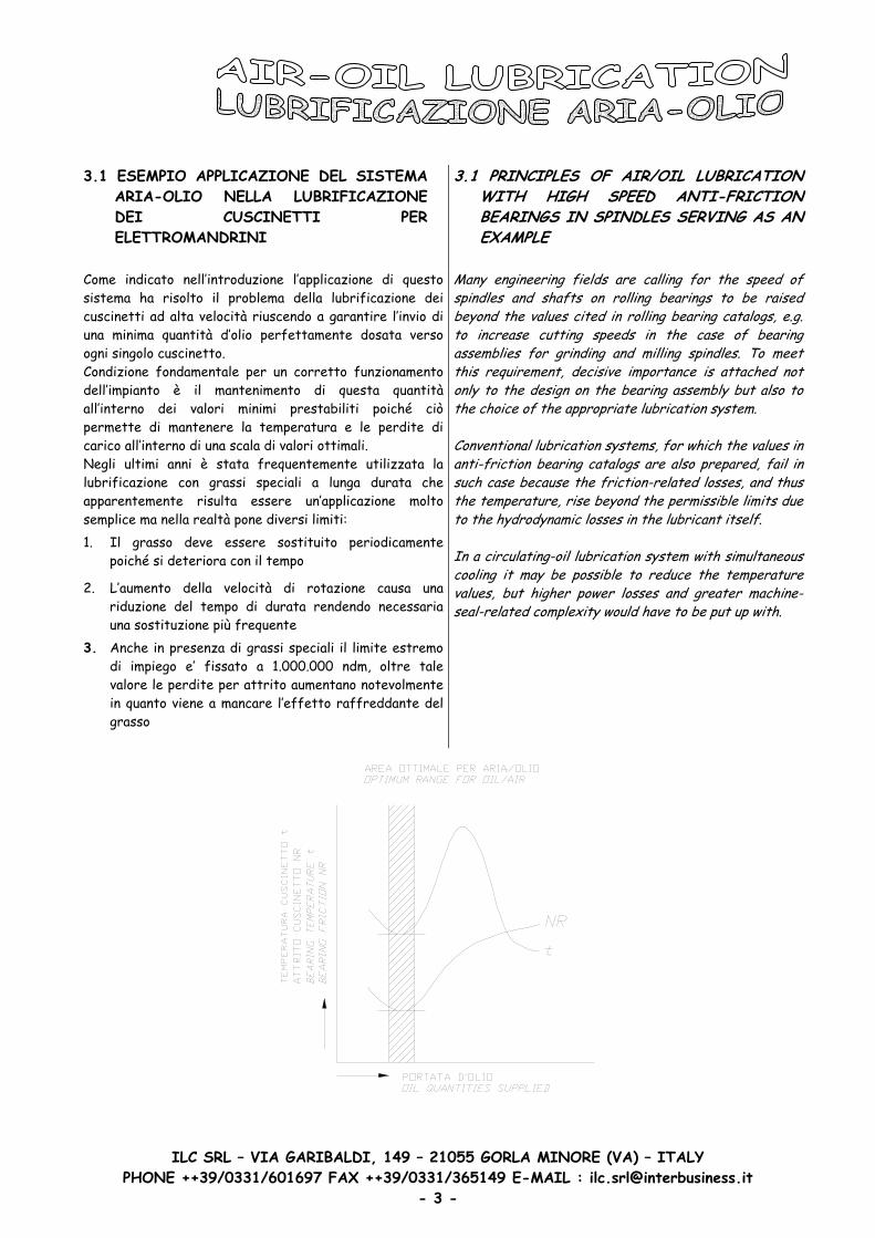
Dal diagramma è possibile notare che le migliori condizioni si raggiungono fornendo una minima quantità d’olio. Per le velocità più elevate il sistema aria-olio è il più appropriato e può, naturalmente, essere usato quando si è alla presenza di basse velocità 3.2 VANTAGGI
- Possibilità di incrementare i valori di rotazione (2.200.000 ndm)
- Invio costante di lubrificante fresco ai cuscinetti
- Riduzione del consumo di lubrificante, 10% rispetto ai classici sistemi a nebbia
- Scelta dell’olio con un largo intervallo di viscosità
- Possibilità di utilizzare lubrificanti con caratteristiche e.p.
- Eliminazione del tempo di rilubrificazione a grasso
- Semplificazione delle tenute dell’elettromandrino
- Protezione dalle impurità esterne grazie alla minima sovrapressione generata all’interno del mandrino
- Nessuna forma di nebbie o inquinamenti
- Riduzione della temperatura del cuscinetto
- Riduzione della potenza impiegata
- Possibilità di inviare la giusta quantità di lubrificante ad ogni singolo cuscinetto
It can be seen from the diagram that the most favorable values in regard to friction losses and temperature are achieved with a minimum supply of oil.
t
Small quantities of lubricant supplied for this purpose are best fed to the bearings in accordance with the principle of air/oil lubrication, since the quanti ies of lubricant can be precisely metered out with this system. In the case of oil mist lubrication, however, it is hardly possible to supply individual bearings in reliably and constant basis with the small quantities required. On the other hand, permanent grease lubrication is very suitable and also used in many cases. But the use of grease lubrication is limited to a speed parameter of
n · dm from < 1 to 1.5*10.000.000 mm*rpm
Not only that, grease change intervals, in conjunction with the replacement of spindles, are greatly and disproportionately shortened within the speed range of n*dm from > 10.000.000 mm*rpm, even when special grease is used
For high speed characteristics air/oil lubrication is therefore the most appropriate system that can, of course, also be used when low speed characteristics are involved
3.2 ADVANTAGES
- Attainment of high speed parameters with anti-friction bearings (up to some 2,200,000 mm · rpm)
- Constantly fresh lubricant at the friction point
- Low consumption of lubricant, some 10% of oil mist lubrication
- Choice of oil within a wide range of viscosities
- Possibility of using oils with ep and adhesive additives
- Elimination of grease relubrication times - Simplified bearing seals - Protection from contamination from the outside due
to the overpressure produced in the bearing itselfby the compressed air
- Non-polluting, no oil mist - Low bearing temperature - Small power losses - Supply of each bearing with the respectively
required quantity of lubricant
PHONE ++39/0331/601697 FAX ++39/0331/365149 E-MAIL : [email protected] - 4 -

ILC SRL – VIA GARIBALDI, 149 – 21055 GORLA MINORE (VA) – ITALY
3.3 DETERMINAZIONE DELLA QUANTITA’ DI LUBRIFICANTE PER SINGOLO PUNTO Non esiste tuttora alcuna formula matematica che determini in modo assoluto la quantità di lubrificante necessaria alla lubrificazione di ogni singolo punto in quanto questo valore dipende notevolmente dal tipo di cuscinetto – dalla larghezza - dal numero delle file e dalle condizioni di lavoro. Onde poter facilitare un calcolo approssimativo della quantità di olio necessaria indichiamo una formula che dovrà essere successivamente verificata con prove pratiche e comparata con i valori espressi nelle tabelle fornite dalle case costruttrici di cuscinetti.
Q = W * D * B
DOVE
Q QUANTITÀ IN MM³/H
W COEFFICIENTE VARIABILE DA 0.01 A 0.03 MM³/H*
D DIAMETRO INTERNO DEL CUSCINETTO IN MM
B DIAMETRO ESTERNO DEL CUSCINETTO IN MM
*0.03 per cuscinetti a rulli cilindrici *0.01 per cuscinetti a sfere ed a rulli a contatto obliquo I valori teorici ottenuti mediante l’applicazione di questa formula dovranno essere incrementati da un minimo di 4 ad un massimo di 20 volte. Non dovrà stupire il valore ottenuto dal calcolo del lubrificante che sicuramente determinerà un valore minimo. Test effettuati hanno dimostrato che quantità d’olio da 120 a 180 mm³/h è ottimale per i cuscinetti degli elettromandrini. Onde poter ottenere una lubrificazione omogenea consigliamo di suddividere la quantità di lubrificante ottenuta in 4-10 cicli / ora. 3.4 LUBRIFICANTI
E’ possibile utilizzare lubrificanti con viscosità da iso vg32 a iso vg100. E’ inoltre possibile utilizzare olii con additivi e.p. soprattutto in caso di carichi elevati e basse velocità. Evitare l’utilizzo di lubrificanti con additivi molikote o similari in quanto potrebbero provocare, causa la scomposizione, problemi di chiusura agli ugelli ed/o ridurre la vita del cuscinetto
3.3 LUBRICANT QUANTITIES FOR ANTI-FRICTION BEARINGS The lubricant quantity depends very much on the typeof bearing, number of rows, width, etc. when determining the lubricant quantity it is therefore always advisable to consult the bearing supplier.
t
In the literature there is the following approximation formula for determina ion of the approximate oil requirements:
Q = W * D * B WHERE
Q QUANTITY IN MM³/HW COEFFICIENT ADJUSTABLE
FROM 0.01 TO 0.03 MM³/H* D INTERNAL BEARING DIAMETER
IN MM B BERING WIDTH IN MM
*0.03 for cylindrical rolling bearings *0.01 for ball and oblique contact roller bearings
In practice, however, the values determined with this formula had to be increased 4 to 20 times. This shows quite clearly that the actual quantity of lubricant per bearing has to be empirically determined for every application. Tests show that lubricant quantities of 120 to 180 mm³/h are, for example, favorable for spindle bearings. It is advisable for the lubricant quantity to be spreadover 4 to 10 injection pulses per hour.
3.4 DEMANDS ON THE LUBRICANT
Oils of iso grades vg 32 to vg 100 have proved to be very suitable. Oils with ep additives are also advisable,especially in the case of high loads and low speeds. Oils with a viscosity lower than iso vg 22 should be avoided since at high loads the load-bearing capacity might not be sufficient anymore, thereby reducing the service life of the bearings. Oils with a high viscosity can be used. On the other hand, oils with molycote additives shouldnot be used, since with these oils there is the danger of molycote being deposited on the nozzle bores, thereby clogging them. Furthermore, The bearing clearance can be critically reduced by plating with molycote particles.
PHONE ++39/0331/601697 FAX ++39/0331/365149 E-MAIL : [email protected] - 5 -

ILC SRL – VIA GARIBALDI, 149 – 21055 GORLA MINORE (VA) – ITALY
3.5 ARIA COMPRESSA
L’aria deve essere secca e filtrata: è richiesta una filtrazione minore o uguale a 5 micron. Al fine di separare l’acqua dall’aria si deve usare un deumidificatore del tipo utilizzato per installazioni in aria compressa con drenaggio semiautomatico. Il volume d’aria necessario per scomporre e trasportare il lubrificante all’interno di una tubazione con ø6x4mm è di ~ 1.500 nl/ora. Questo valore è stato calcolato per lubrificanti aventi viscosità compresi fra le classi Iso vg-32 e Iso vg-68. Lubrificanti con densità superiori richiedono un volume maggiore. La pressione dell’aria deve essere regolata per vincere le contropressioni in gioco e dovrà avere una pressione minima di 6 bar all’ingresso dell’unità di lubrificazione. 3.6 INVIO DEL LUBRIFICANTE La linea di alimentazione del lubrificante deve essere realizzata mediante una tubazione flessibile di nylon/rilsan ø 6x4 che , grazie alla semi-trasparenza , permette di avere un ulteriore controllo visivo del passaggio del lubrificante. L’orientamento della tubazione può essere indirizzato verso l’alto o verso il basso senza influire minimamente sul funzionamento. La lunghezza della tubazione deve essere di min. 1m e max. 10m. Nel caso in cui la distanza fra il gruppo di alimentazione mandrino sia inferiore ad 1m si dovrà prevedere una tubazione a spirale (4/5 spire). E’ consigliabile prevedere questa tubazione in prossimità del punto da lubrificare anche in caso di distanze vicine ai valori massimi (10m). E’ possibile montarla orizzontalmente o inclinata di max. 30° rispetto all’asse orizzontale. La funzione di questa spirale consiste nel creare , quando viene disattivato l’impianto ed il relativo flusso di aria , un piccolo serbatoio di raccolta olio molto utile alla successiva attivazione in quanto permetterà una lubrificazione immediata del cuscinetto senza attendere il primo ciclo programmato. Si devono inoltre evitare variazioni di sezione e giunzioni nelle tubazioni di linea.
t ,
3.5 COMPRESSED AIR
The air has to be dry and filtered; filter fineness < 5 micron. A cus omary water separator of the kind usedon compressed-air installations if possible with semiautomatic drainage, will suffice for the separation of water. The volume of air required for proper transport of the oil in a tube with an internal diameter of 4 mm amounts to 1500 nl/h. This value applies to oils of viscosity grades Iso vg 32 to Iso vg 100. Higher values have to be expected in the case of high-viscosity oils or oils with different adhesive properties. The air pressure must be adjusted in such a way thatthis volume can pass through every line after pressurelosses in the line and the bearings are taken into account. The air pressure available at the inlet of theunit (compressed air system) should amount to 6 bars.
3.6 LUBRICANT SUPPLY (CRITERIA, BEARING DESIGN, ETC.)
l i l li
The line, e.g. 6X4 flexible plastic tubing in which the oil transport can be clearly seen, can be laid so that it drops or rises. The minimum length of this line amountsto 1 m. The maximum length of the line may well reach10 m. If the distance between the unit and bearing isless than 1 m, this line must be laid in the form of a helical coil. In the case of very long lines it is likewiseadvisable for the supply tube to be laid as close as possible to the bearing in the form of a helical coil with approx. 5 turns. The central axis of the helical coil shou d be either hor zonta or inc ned up to an angle of approx. 30° from the horizontal. The oil from the helical line should collect in the bottom part of the coil after the compressed air is switched off so that the bearing is supplied with oil shortly after the compressed air is switched on again. Changes in cross-sections must be avoided, especially in the case of bends. If they cannot be avoided, gradualtransitions must be provided. In the case of tube connectors (as few as possible) see to it that no oil islost or collected there.
PHONE ++39/0331/601697 FAX ++39/0331/365149 E-MAIL : [email protected] - 6 -

ILC SRL – VIA GARIBALDI, 149 – 21055 GORLA MINORE (VA) – ITALY
Il sistema d’alimentazione dell’olio varia in funzione del tipo di cuscinetto e della costruzione del supporto. Nella figura sono mostrati alcuni esempi. E’ indispensabile prevedere una linea per lo scarico d’eventuali depositi d’olio formatisi nelle zone basse dei cuscinetti. Il diametro del foro di scarico non dovrà essere inferiore ai 5 mm.
The way the lubricant is fed to the bearing depends on the type of bearing assembly’s design features. Some examples are in the figure.
t t
A drain must be provided for the oil delivered to keep an oil sump from forming. The diameter of this drainage hole mus amount a least 5 mm
PHONE ++39/0331/601697 FAX ++39/0331/365149 E-MAIL : [email protected] - 7 -
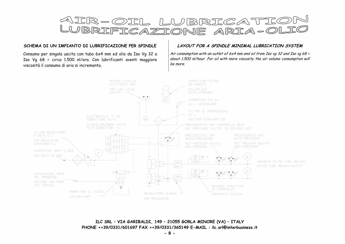
SCHEMA DI UN IMPIANTO DI LUBRIFICAZIONE PER SPINDLE LAYOUT FOR A SPINDLE MINIMAL LUBRICATION SYSTEM
Consumo per singola uscita con tubo 6x4 mm ed olio da Iso Vg 32 a Iso Vg 68 = circa 1.500 nl/ora. Con lubrificanti aventi maggiore viscosità il consumo di aria si incrementa.
Air consumption with an outlet of 6x4 mm and oil from Iso vg 32 and Iso vg 68 = about 1.500 nl/hour. For oil with more viscosity the air volume consumption will be more.
ILC SRL – VIA GARIBALDI, 149 – 21055 GORLA MINORE (VA) – ITALY PHONE ++39/0331/601697 FAX ++39/0331/365149 E-MAIL : [email protected]
- 8 -

PRINCIPALI COMPONENTI MAIN COMPONENTS
ILC SRL – VIA GARIBALDI, 149 – 21055 GORLA MINORE (VA) – ITALY PHONE ++39/0331/601697 FAX ++39/0331/365149 E-MAIL : [email protected]
- 9 -

ILC SRL – VIA GARIBALDI, 149 – 21055 GORLA MINORE (VA) – ITALY
FUNZIONAMENTO OPERATION
Sono stati progettati per ottenere una precisa e corretta lubrificazione minimale di organi rotanti ad alte velocità e/o superfici a contatto con carichi elevati. Il sistema aria-olio è un metodo di lubrificazione per l’ottenimento di portate minimali, che consiste nel rilascio di quantità molto piccole e ciclicamente dosate di lubrificante in un tubo di diametro opportuno, in cui scorre un flusso continuo d’aria compressa a bassa pressione. A intervalli di tempo pre-determinati l’olio viene erogato da una micropompa pneumatica e immesso in una camera di miscelazione con l’aria. Da qui, le gocce, sono trasportate lungo la superficie interna della tubazione di mandata in direzione del punto da lubrificare, dove sono erogate in forma di fine e continuo soffio d’aria umida d’olio. Le micropompe pneumatiche vengono eccitate al termine del tempo di pausa impostato nel MINI-PLC interno o nel controllo della macchina. Ad ogni azionamento una piccolissima quantità di lubrificante viene aspirata dal serbatoio ed inviata alla camera di miscelazione situata nella sottobase della micropompe. Una volta raggiunta la camera di miscelazione l’olio viene scomposto in particelle grosse e trasportato nelle tubazioni di collegamento alle utenze finali mediante un flusso d’aria costante. La pressione dell’aria nelle tubazioni di collegamento e’ mantenuta sotto controllo tramite il gruppo di controllo pressione posto nelle mandate delle unità. Un pressostato controlla costantemente il valore di pressione del flusso dell’aria nelle tubazioni secondarie (verifica di pressione minima = rottura tubazioni). Un ulteriore pressostato verifica che non si creino occlusioni nelle tubazioni finali (verifica di pressione massima = chiusura tubazione) Il passaggio del lubrificante dalla micropompe alla camera di dosaggio è controllato mediante il sensore induttivo posto nella parte terminale della micropompe. Tutte le unità sono inoltre dotate di sensore di minimo livello elettrico ed a richiesta possono essere equipaggiate con un MINI-PLC in grado di inviare i comandi di pausa e lavoro e raccogliere tutti i segnali di eventuali anomalie. Questo segnale può inoltre essere trasmesso a distanza. La pompa del vuoto serve a recuperare eventuali depositi d’olio dall’interno dell’elettromandrino.
They can be used to lubricate in the correct way high-speed bearings and surfaces in contacts with high loads. The air-oil system is a method of lubrication for a minimal flow obtainment, which depends on a minimal release of quantity and the lubrication is frequently measured out in a suitable tube diameter, in which flows compressed air under minimal pressure. By predetermined time intervals the oil will be distributed and will be put on to the mixing block withcompressed air.
From here, the feeded drops are conveyed lengthwaystowards the point to be lubricating, where they are supplied like a thin and continuous breathing of a humid oil-air mixture. The micro pneumatic pumps are switched on at the end of the pause time set with the PLC “Millenium” (orwith the machine PLC). They feed a metered quantityof oil from the reservoir to the mixing chambers of the pump bases. The oil is transported to the frictionpoints by the continuous flow of compressed air. The air pressure in the delivery lines is monitored from the PLC “Millenium” by mean of pressure switches. The oil in the delivery line is monitored from the PLC “Millenium” by mean of inductive sensors. The oil level in the reservoir is monitored from the PLC “Millenium” by mean of a float switch. The PLC “Millenium” will indicate a fault if the air pressure required (the secondary line is broken) is not reached or if is too high (the secondary line is plugged) , if the oil is not going in the delivery line orif the oil falls below the minimum level in the reservoir. Of course it is possible to check all the fault by meanof the machine PLC. In case has to be recovered air/oil from the spindle it will be necessary to use a vacuum pump.
PHONE ++39/0331/601697 FAX ++39/0331/365149 E-MAIL : [email protected] - 10 -

ILC SRL – VIA GARIBALDI, 149 – 21055 GORLA MINORE (VA) – ITALY
UNITA’ CON SCATOLA DI PROTEZIONE UNITS WITH BOX
CARATTERISTICHE FEATURES N.MICROPOMPE DA 1 A 4 PUMPS NUMBER FROM 1 TO 4
PORTATA DA 1.5 A 41 MM³/CICLO DISCHARGE FROM 1.5 TO 41 MM³/STROKE FREQ. CICLI MAX 1 OGNI 5 SECONDI STROKES 1 EVERY 5 SECONDS LUBRIFICANTI DA ISO VG-32 A ISO VG-68 LUBRICANTS FROM ISO VG 32 TO ISO VG 100 - -
SERBATOIO NYLON 3.6 L RESERVOIR NYLON 3.6 L MIN. LIV. ELETTRICO 1 A 250 V AC – 200 V DC 50 W LOW LEVEL SWITCH 1 A 250 V AC – 200 V DC 50 W
FILTRO DI CARICO 250 µ REFILL STRAINER 250 µ FILTRO ASPIRAZIONE 10 µ SUCTION STRAINER 10 µ
TEMPERATURA DA O° C A 60 °C TEMPERATURE FROM O° C TO 60 °C TUBAZIONI MANDATA 6x4 MM 12 M LUNG. MAX DELIVERY TUBE 6x4 MM 12 M MAX LENGTH
CODICE ORDINAZIONE – CODES FOR ORDER
CODICE - CODE MANDATE - DELIVERIES 70.500.1 1 70.500.2 2 70.500.3 3 70.500.4 4
Al fine di completare l’unita’ bisogna ordinare un elemento di controllo per ogni singola uscita. Vedere esempi a pagina 13. A richiesta sono disponibili altre versioni per poter soddisfare tutte le esigenze.
To complete the system have to be ordered an inductive sensor and a pressure switch for each outlet. See page 13 forexample.
lOn request can be supplied different versions to satisfy all the possible app ications.
PHONE ++39/0331/601697 FAX ++39/0331/365149 E-MAIL : [email protected] - 11 -
ILC SRL – VIA GARIBALDI, 149 – 21055 GORLA MINORE (VA) – ITALY
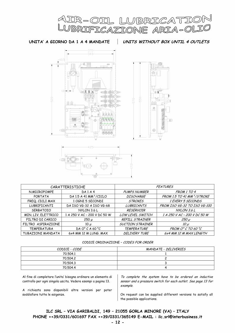
UNITA’ A GIORNO DA 1 A 4 MANDATE UNITS WITHOUT BOX UNTIL 4 OUTLETS
CARATTERISTICHE FEATURES
N.MICROPOMPE DA 1 A 4 PUMPS NUMBER FROM 1 TO 4 PORTATA DA 1.5 A 41 MM³/CICLO DISCHARGE FROM 1.5 TO 41 MM³/STROKE
FREQ. CICLI MAX 1 OGNI 5 SECONDI STROKES 1 EVERY 5 SECONDS LUBRIFICANTI DA ISO VG-32 A ISO VG-68 LUBRICANTS FROM ISO VG 32 TO ISO VG 100 - -
SERBATOIO NYLON 3.6 L RESERVOIR NYLON 3.6 L MIN. LIV. ELETTRICO 1 A 250 V AC – 200 V DC 50 W LOW LEVEL SWITCH 1 A 250 V AC – 200 V DC 50 W
FILTRO DI CARICO 250 µ REFILL STRAINER 250 µ FILTRO ASPIRAZIONE 10 µ SUCTION STRAINER 10 µ
TEMPERATURA DA O° C A 60 °C TEMPERATURE FROM O° C TO 60 °C TUBAZIONI MANDATA 6x4 MM 12 M LUNG. MAX DELIVERY TUBE 6x4 MM 12 M MAX LENGTH
CODICE ORDINAZIONE – CODES FOR ORDER
CODICE - CODE MANDATE - DELIVERIES 70.504.1 1 70.504.2 2 70.504.3 3 70.504.4 4
Al fine di completare l’unita’ bisogna ordinare un elemento di controllo per ogni singola uscita. Vedere esempi a pagina 13. A richiesta sono disponibili altre versioni per poter soddisfare tutte le esigenze.
To complete the system have to be ordered an inductive sensor and a pressure switch for each outlet. See page 13 forexample.
On request can be supplied different versions to satisfy all the possible applications.
PHONE ++39/0331/601697 FAX ++39/0331/365149 E-MAIL : [email protected] - 12 -

ILC SRL – VIA GARIBALDI, 149 – 21055 GORLA MINORE (VA) – ITALY
CODICI DI ORDINAZIONE PER ELEMENTI DI CONTROLLO SISTEMA
CODE DESCRIZIONE 70.510.0 CONTROLLO DI FLUSSO INDUTTIVO NPN 70.510.1 CONTROLLO DI FLUSSO INDUTTIVO PNP 70.510.2 GRUPPO CONTROLLO MINIMA PRESSIONE ARIA LINEA SECONDARIA 14.669.9 POMPA VUOTO CON SERBATOIO L 0.35 PER UNITA’ CON SCATOLA DI PROTEZIONE 14.669.8 POMPA VUOTO CON SERBATOIO L 0.35 PER UNITA’ A GIORNO 70.510.5 GRUPPO CONTROLLO MASSIMA E MINIMA PRESSIONE ARIA LINEA SECONDARIA 70.510.3 PLC “MILLENIUM” 24 V DC 6 IN – 4 USCITE PER UNITA’ CON SCATOLA DI PROTEZIONE 70.510.4 PLC “MILLENIUM” 24 V DC 12 IN – 8 USCITE 70.510.6 PLC “MILLENIUM” 24 V DC 6 IN – 4 USCITE PER UNITA’ A GIORNO 70.510.9 PRESSOSTATO “NA” PER CONTROLLARE L’ARIA PRINCIPALE
CODES FOR ORDER ELEMENTS TO CONTROL THE SYSTEM
CODE DESCRIPTION 70.510.0 BLOCK TO CONTROL OIL FLOW WITH INDUCTIVE SENSOR NPN 70.510.1 BLOCK TO CONTROL OIL FLOW WITH INDUCTIVE SENSOR PNP 70.510.2 BLOCK TO CONTROL LOW AIR PRESSURE WITH PRESSURE SWITCH 14.669.9 VACUUM PUMP COMPLETE OF 0.35 L RESERVOIR FOR BOX VERSION 14.669.8 VACUUM PUMP COMPLETE OF 0.35 L RESERVOIR FOR WITHOUT BOX VERSION 70.510.5 BLOCK TO CONTROL LOW AND HIGH AIR PRESSURE WITH PRESSURE SWITCHES 70.510.3 PLC “MILLENIUM” 24 V DC 6 IN – 4 OUT FOR BOX VERSION 70.510.4 PLC “MILLENIUM” 24 V DC 12 IN – 8 OUT 70.510.6 PLC “MILLENIUM” 24 V DC 6 IN – 4 OUT FOR WITHOUT BOX VERSION 70.510.9 “NO” PRESSURE SWITCH TO CONTROL MAIN AIR
COME ORDINARE
ESEMPIO N. 1 Unità spindle con scatola di protezione per due punti completa di controllo olio, controllo minima pressione aria, controllo massima pressione aria e plc. Senza pompa del vuoto
CODICI DA ORDINARE N. 1 70.500.2 N. 2 70.510.0 O 70.510.1 N. 2 70.510.5 N. 1 70.510.3 ESEMPIO N. 2 Unità spindle a giorno per quattro punti completa di controllo olio, controllo minima pressione aria, plc e pompa del vuoto
CODICI DA ORDINARE N. 1 70.504.4 N. 4 70.510.0 O 70.510.1 N. 4 70.510.2 N. 1 70.510.6 N. 1 14.669.8
HOW TO ORDER
EXAMPLE N. 1
1
1
Unit with box for two points complete with oil flowcontrol, low and air pressure control and plc. Without vacuum pump
CODES HAVE TO BE ORDERED N. 1 70.500.2 N. 2 70.5 0.0 OR 70.510.1 N. 2 70.510.5 N. 1 70.510.3 EXAMPLE N. 2 Unit without box for four points complete with oilflow control, low air pressure control, plc and vacuum pump
CODES HAVE TO BE ORDERED N. 1 70.504.4 N. 4 70.5 0.0 O 70.510.1 N. 4 70.510.2 N. 1 70.510.6 N. 1 14.669.8
PHONE ++39/0331/601697 FAX ++39/0331/365149 E-MAIL : [email protected] - 13 -
ILC SRL – VIA GARIBALDI, 149 – 21055 GORLA MINORE (VA) – ITALY
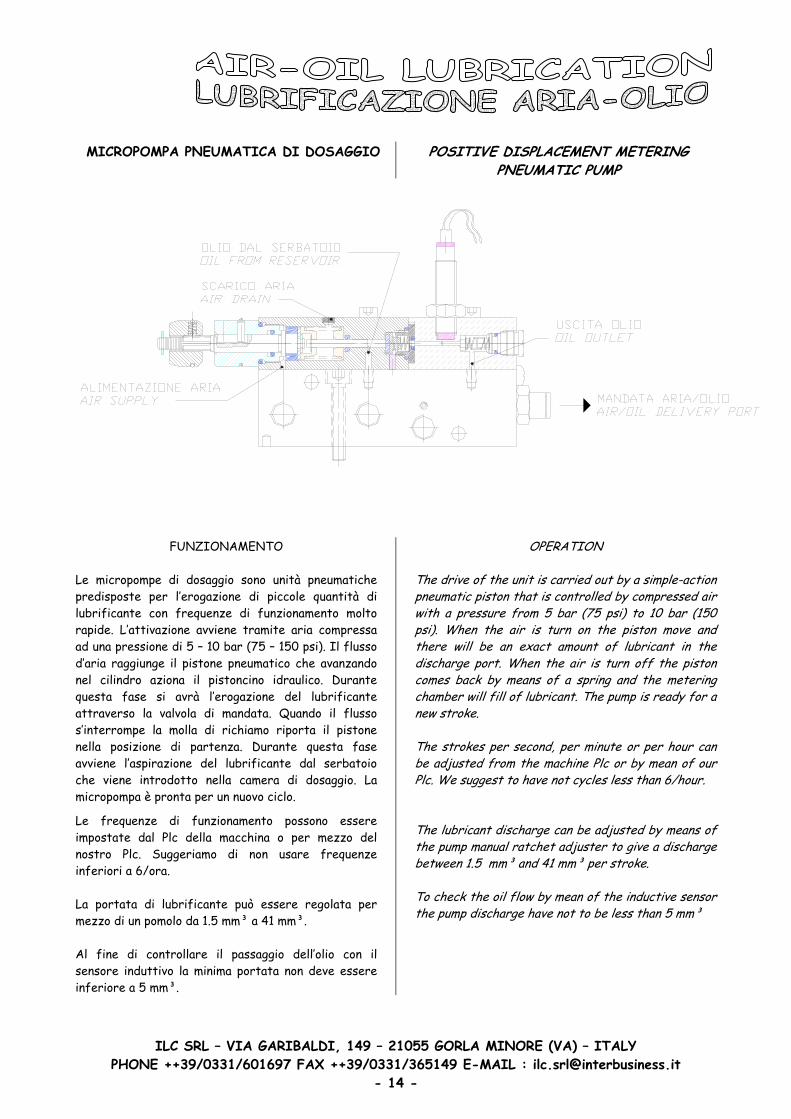
MICROPOMPA PNEUMATICA DI DOSAGGIO
POSITIVE DISPLACEMENT METERING PNEUMATIC PUMP
FUNZIONAMENTO
Le micropompe di dosaggio sono unità pneumatiche predisposte per l’erogazione di piccole quantità di lubrificante con frequenze di funzionamento molto rapide. L’attivazione avviene tramite aria compressa ad una pressione di 5 – 10 bar (75 – 150 psi). Il flusso d’aria raggiunge il pistone pneumatico che avanzando nel cilindro aziona il pistoncino idraulico. Durante questa fase si avrà l’erogazione del lubrificante attraverso la valvola di mandata. Quando il flusso s’interrompe la molla di richiamo riporta il pistone nella posizione di partenza. Durante questa fase avviene l’aspirazione del lubrificante dal serbatoio che viene introdotto nella camera di dosaggio. La micropompa è pronta per un nuovo ciclo.
Le frequenze di funzionamento possono essere impostate dal Plc della macchina o per mezzo del nostro Plc. Suggeriamo di non usare frequenze inferiori a 6/ora. La portata di lubrificante può essere regolata per mezzo di un pomolo da 1.5 mm³ a 41 mm³. Al fine di controllare il passaggio dell’olio con il sensore induttivo la minima portata non deve essere inferiore a 5 mm³.
OPERATION
The drive of the unit is carried out by a simple-action pneumatic piston that is controlled by compressed airwith a pressure from 5 bar (75 psi) to 10 bar (150 psi). When the air is turn on the piston move and there will be an exact amount of lubricant in the discharge port. When the air is turn off the piston comes back by means of a spring and the metering chamber will fill of lubricant. The pump is ready for a new stroke.
The strokes per second, per minute or per hour can be adjusted from the machine Plc or by mean of our Plc. We suggest to have not cycles less than 6/hour. The lubricant discharge can be adjusted by means of the pump manual ratchet adjuster to give a dischargebetween 1.5 mm³ and 41 mm³ per stroke. To check the oil flow by mean of the inductive sensor the pump discharge have not to be less than 5 mm³
PHONE ++39/0331/601697 FAX ++39/0331/365149 E-MAIL : [email protected] - 14 -

ILC SRL – VIA GARIBALDI, 149 – 21055 GORLA MINORE (VA) – ITALY
REGOLAZIONE DELLA PORTATA DEL CICLO HOW TO AD JUST THE DISCHARGE PER STROKE
Ruotare il pomolo in senso orario per ridurre la quantità d’olio ed in senso antiorario per incrementarla.
Turning the adjuster clockwise will decrease the pump discharge and turning the adjuster anti-clockwise will increase the pump discharge.
PHONE ++39/0331/601697 FAX ++39/0331/365149 E-MAIL : [email protected] - 15 -

SOTTOBASE POMPA PER MISCELAZIONE ARIA-OLIO PUMP BASE TO MIX AIR AND OIL
ILC SRL – VIA GARIBALDI, 149 – 21055 GORLA MINORE (VA) – ITALY PHONE ++39/0331/601697 FAX ++39/0331/365149 E-MAIL : [email protected]
- 16 -
ILC SRL – VIA GARIBALDI, 149 – 21055 GORLA MINORE (VA) – ITALY
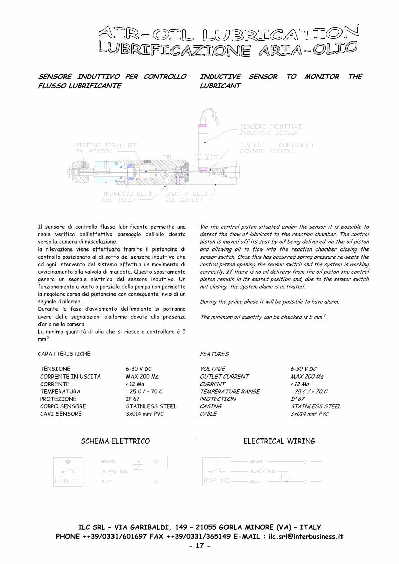
SENSORE INDUTTIVO PER CONTROLLO FLUSSO LUBRIFICANTE
INDUCTIVE SENSOR TO MONITOR THE LUBRICANT
Il sensore di controllo flusso lubrificante permette una reale verifica dell’effettivo passaggio dell’olio dosato verso la camera di miscelazione. la rilevazione viene effettuata tramite il pistoncino di controllo posizionato al di sotto del sensore induttivo che ad ogni intervento del sistema effettua un movimento di avvicinamento alla valvola di mandata. Questo spostamento genera un segnale elettrico del sensore induttivo. Un funzionamento a vuoto o parziale della pompa non permette la regolare corsa del pistoncino con conseguente invio di un segnale d’allarme. Durante la fase d’avviamento dell’impianto si potranno avere delle segnalazioni d’allarme dovute alla presenza d’aria nella camera. La minima quantità di olio che si riesce a controllare è 5 mm³ CARATTERISTICHE TENSIONE 6-30 V DC CORRENTE IN USCITA MAX 200 Ma CORRENTE < 12 Ma TEMPERATURA - 25 C / + 70 C PROTEZIONE IP 67 CORPO SENSORE STAINLESS STEEL CAVI SENSORE 3x014 mm² PVC
V a the control piston situated under the sensor it is possible to detect the flow of lubricant to the reaction chamber. The control piston is moved off its seat by oil being del vered via the oil piston and allow ng oil to flow into the reaction chamber closing the sensor switch. Once this has occurred spring pressure re-seats the control piston opening the sensor switch and the system is working correctly. If there is no oil delivery from the oil piston the controlpiston remain in its seated position and, due to the sensor switch not closing, the system alarm is activated.
i
ii
l t
During the prime phase it will be possible to have alarm.
The minimum oi quan ity can be checked is 5 mm³.
FEATURES VOLTAGE 6-30 V DCOUTLET CURRENT MAX 200 Ma CURRENT < 12 MaTEMPERATURE RANGE - 25 C / + 70 C PROTECTION IP 67 CASING STAINLESS STEELCABLE 3x014 mm² PVC
SCHEMA ELETTRICO ELECTRICAL WIRING
PHONE ++39/0331/601697 FAX ++39/0331/365149 E-MAIL : [email protected] - 17 -

ILC SRL – VIA GARIBALDI, 149 – 21055 GORLA MINORE (VA) – ITALY
GRUPPO DI CONTROLLO PRESSIONE MINIMA DELL’ARIA NELLA LINEA PRINCIPALE
PRESSURE SWITCH TO CHECK AIR LOW FLOW IN THE MAIN LINE
Controlla il valore della pressione dell’aria all’uscita dell’elettrovalvola che invia aria all’impianto. Il contatto normalmente aperto è attivato dal passaggio dell’aria proveniente dall’elettrovalvola ed un abbassamento del valore al disotto di quanto impostato provoca un ritorno allo stato di partenza del contatto ed un conseguente invio del segnale d’allarme. CARATTERISTICHE PRESSIONE ESERCIZIO 2 – 10 BAR SETTATO 3.5 BAR CONTATTO NORMALMENTE APERTO TENSIONE MAX 220 V AC POTENZA MAX 100 VA
CORRENTE 0.5 RESISTIVA 0.25 INDUTTIVA
TEMPERATURA DA -5 ºC A + 60 ºC PROTEZIONE IP 54 CICLI MASSIMI 200/1’
This is situated after the solenoid valve sending air in the delivery lines. The switch is normally open and the pressureflow of air closes the contact. If there is no airflow the switch changes to open thus activating the system alarm.
FEATURES
OPERATING PRESSURE 2 – 10 BAR FACTORY SET 3.5 BAR CONTACT NORMALLY OPEN MAX VOLTAGE 220 V AC MAX POWER 100 VA
CURRENT 0.5 RESISTIVE 0.25 INDUCTIVE
WORKING TEMPERATURE FROM -5 ºC TO + 60 ºC PROTECTION IP 54 MAX CYCLES 200/1’
Importante: Il valore settato non può essere variato. A richiesta sono disponibili pressostati tarati secondo le esigenze del cliente.
Important: The factory set values cannot be changed. On request we can supply pressure switches set on the customers need.
PHONE ++39/0331/601697 FAX ++39/0331/365149 E-MAIL : [email protected] - 18 -

ILC SRL – VIA GARIBALDI, 149 – 21055 GORLA MINORE (VA) – ITALY
GRUPPO DI CONTROLLO PRESSIONE MINIMA DELL’ARIA
PRESSURE SWITCH TO CHECK AIR LOW FLOW
Installato direttamente nelle mandate delle linee secondarie controlla il valore della pressione dell’aria nelle tubazioni di collegamento alle utenze finali. Il contatto normalmente aperto è attivato dal passaggio dell’aria proveniente dall’elettrovalvola ed un abbassamento del valore al disotto di quanto impostato provoca un ritorno allo stato di partenza del contatto ed un conseguente invio del segnale d’allarme. CARATTERISTICHE PRESSIONE ESERCIZIO 0.15 – 2 BAR SETTATO 1 BAR CONTATTO NORMALMENTE APERTO TENSIONE MAX 220 V AC POTENZA MAX 100 VA
CORRENTE 0.5 RESISTIVA 0.25 INDUTTIVA
TEMPERATURA DA -5 ºC A + 60 ºC PROTEZIONE IP 54 CICLI MASSIMI 200/1’
This is situated on the delivery line. The switch is normallyopen and the pressure flow of air closes the contact. If there is no air flow the switch changes to open thus activating the system alarm.
FEATURES
OPERATING PRESSURE 0.15 – 2 BAR FACTORY SET 1 BAR CONTACT NORMALLY OPEN MAX VOLTAGE 220 V AC MAX POWER 100 VA
CURRENT 0.5 RESISTIVE 0.25 INDUCTIVE
WORKING TEMPERATURE FROM -5 ºC TO + 60 ºC PROTECTION IP 54 MAX CYCLE 200/1’
Importante: Il valore settato non può essere variato. A richiesta sono disponibili pressostati tarati secondo le esigenze del cliente.
Important: The factory set values cannot be changed. On request we can supply pressure switches set on the customers need.
PHONE ++39/0331/601697 FAX ++39/0331/365149 E-MAIL : [email protected] - 19 -
ILC SRL – VIA GARIBALDI, 149 – 21055 GORLA MINORE (VA) – ITALY
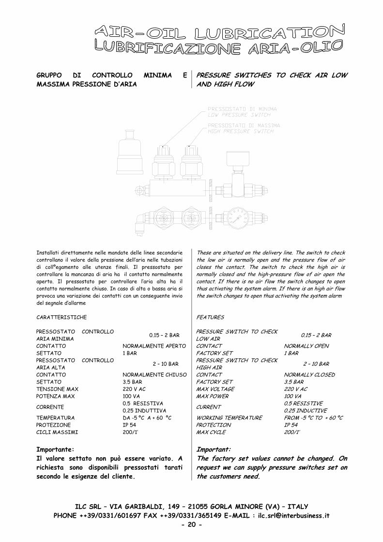
GRUPPO DI CONTROLLO MINIMA E MASSIMA PRESSIONE D’ARIA
PRESSURE SWITCHES TO CHECK AIR LOW AND HIGH FLOW
Installati direttamente nelle mandate delle linee secondarie controllano il valore della pressione dell’aria nelle tubazioni di collºegamento alle utenze finali. Il pressostato per controllare la mancanza di aria ha il contatto normalmente aperto. Il pressostato per controllare l’aria alta ha il contatto normalmente chiuso. In caso di alta o bassa aria si provoca una variazione dei contatti con un conseguente invio del segnale d’allarme CARATTERISTICHE PRESSOSTATO CONTROLLO ARIA MINIMA 0.15 – 2 BAR
CONTATTO NORMALMENTE APERTO SETTATO 1 BAR PRESSOSTATO CONTROLLO ARIA ALTA 2 – 10 BAR
CONTATTO NORMALMENTE CHIUSO SETTATO 3.5 BAR TENSIONE MAX 220 V AC POTENZA MAX 100 VA
CORRENTE 0.5 RESISTIVA 0.25 INDUTTIVA
TEMPERATURA DA -5 ºC A + 60 ºC PROTEZIONE IP 54 CICLI MASSIMI 200/1’
These are situa ed on the delivery line. The switch to check the low air is normally open and the pressure flow of air closes the con act. The switch to check the high air is normally closed and the high-pressure flow of air open the contact. If there is no air flow the switch changes to openthus activating the system alarm. If there is an high air flow the switch changes to open thus activating the system alarm
t
t
FEATURES
PRESSURE SWITCH TO CHECK LOW AIR 0.15 – 2 BAR
CONTACT NORMALLY OPEN FACTORY SET 1 BAR PRESSURE SWITCH TO CHECK HIGH AIR 2 – 10 BAR
CONTACT NORMALLY CLOSED FACTORY SET 3.5 BAR MAX VOLTAGE 220 V AC MAX POWER 100 VA
CURRENT 0.5 RESISTIVE 0.25 INDUCTIVE
WORKING TEMPERATURE FROM -5 ºC TO + 60 ºC PROTECTION IP 54MAX CYCLE 200/1’
Importante: Il valore settato non può essere variato. A richiesta sono disponibili pressostati tarati secondo le esigenze del cliente.
Important: The factory set values cannot be changed. On request we can supply pressure switches set on the customers need.
PHONE ++39/0331/601697 FAX ++39/0331/365149 E-MAIL : [email protected] - 20 -

ILC SRL – VIA GARIBALDI, 149 – 21055 GORLA MINORE (VA) – ITALY
POMPA VUOTO CON SERBATOIO PER UNITA’ CON SCATOLA DI PROTEZIONE
VACUUM PUMP WITH RESERVOIR FOR BOX VERSION
Nel caso sia necessario recuperare automaticamente eventuali depositi d’olio dall’interno dell’elettromandrino e’ possibile equipaggiare le unita’ spindle di una pompa per vuoto. Questo apparecchio e’ completo di serbatoio silenziatore filtro per aria e manometro.
Vacuum generators operate using the Venturi principleand thanks to a special silencer installed in their outlet, they are particularly noiseless. They are currently equipped with a vacuum gauge for the direct reading of the vacuum degree.
CARATTERISTICHE - FEATURES
PRESSIONE DI ESERCIZIO WORKING PRESSURE Bar 4 5 6
VUOTO FINALE FINAL VACUUM -Kpa 60 73 85
Mbar 400 270 150 CONSUMO ARIA AIR CONSUMPTION Nl/s 2.3 2.7 3.2
QUANTITA’ D’ARIA ASPIRATA SUCKED AIR CAPACITY
Cum/h Mc/h 7.2 7.7 8.2
TEMPERATURA ESERCIZIO WORKING TEMPERATURE °C - 20 / + 80
I valori indicati sono riferiti a normali condizioni di pressione atmosferica (1013 mbar) e con pressione di lavoro costante.
All the vacuum values shown in the table are valid at the normal atmospheric pressure of 1013 mbar and obtained with a constant working pressure.
14.669.9
PHONE ++39/0331/601697 FAX ++39/0331/365149 E-MAIL : [email protected] - 21 -

ILC SRL – VIA GARIBALDI, 149 – 21055 GORLA MINORE (VA) – ITALY
POMPA VUOTO CON SERBATOIO PER UNITA’ SENZA SCATOLA DI PROTEZIONE
VACUUM PUMP WITH RESERVOIR FOR VERSION WITHOUT BOX
Nel caso sia necessario recuperare automaticamente eventuali depositi d’olio dall’interno dell’elettromandrino e’ possibile equipaggiare le unita’ spindle di una pompa per vuoto. Questo apparecchio e’ completo di serbatoio silenziatore filtro per aria e manometro.
Vacuum generators operate using the Venturi principleand thanks to a special silencer installed in their outlet, they are particularly noiseless. They are currently equipped with a vacuum gauge for the direct reading of the vacuum degree.
CARATTERISTICHE - FEATURES
PRESSIONE DI ESERCIZIO WORKING PRESSURE Bar 4 5 6
VUOTO FINALE FINAL VACUUM -Kpa 60 73 85
Mbar 400 270 150 CONSUMO ARIA AIR CONSUMPTION Nl/s 2.3 2.7 3.2
QUANTITA’ D’ARIA ASPIRATA SUCKED AIR CAPACITY
Cum/h Mc/h 7.2 7.7 8.2
TEMPERATURA ESERCIZIO WORKING TEMPERATURE °C - 20 / + 80
I valori indicati sono riferiti a normali condizioni di pressione atmosferica (1013 mbar) e con pressione di lavoro costante.
All the vacuum values shown in the table are valid at the normal atmospheric pressure of 1013 mbar and obtained with a constant working pressure.
14.669.8
PHONE ++39/0331/601697 FAX ++39/0331/365149 E-MAIL : [email protected] - 22 -
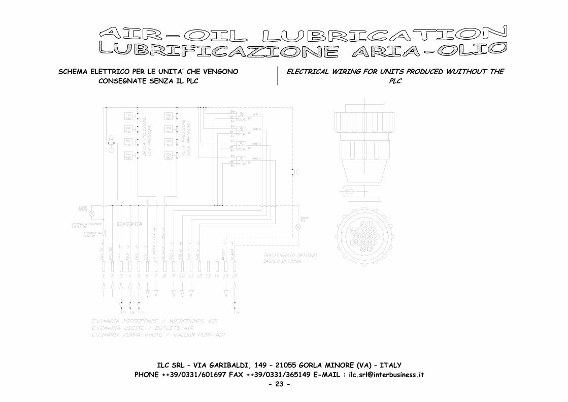
SCHEMA ELETTRICO PER LE UNITA’ CHE VENGONO CONSEGNATE SENZA IL PLC
ELECTRICAL WIRING FOR UNITS PRODUCED WUITHOUT THE PLC
ILC SRL – VIA GARIBALDI, 149 – 21055 GORLA MINORE (VA) – ITALY PHONE ++39/0331/601697 FAX ++39/0331/365149 E-MAIL : [email protected]
- 23 -
ILC SRL – VIA GARIBALDI, 149 – 21055 GORLA MINORE (VA) – ITALY
SERBATOIO PRESSURIZZATO PRESSURIZED RESERVOIR
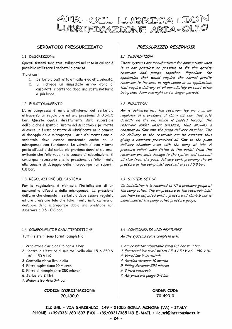
1.1 DESCRIZIONE
Questi sistemi sono stati sviluppati nel caso in cui non è possibile utilizzare i serbatoi a gravità.
Tipici casi: 1. Serbatoio costretto a traslare ad alta velocità. 2. Si richiede un immediato arrivo d’olio ai
cuscinetti ripartendo dopo una sosta notturna o più lunga.
1.1 DESCRIPTION
These systems are manufactured for applications when it is not practical or possible to fit the gravity reservoir and pumps together. Especially for application that would require the normal gravity reservoir to traverse at high speed or on applications that require delivery of oil immediately on start afterbeing shut down overnight or for longer periods.
1.2 FUNZIONAMENTO
L’aria compressa è inviata all’interno del serbatoio attraverso un regolatore ad una pressione di 0.5-2.5 bar. Questa agisce direttamente sulla superficie dell’olio che è spinto all’uscita del serbatoio e permette di avere un flusso costante di lubrificante nella camera di dosaggio della micropompa. L’aria d’alimentazione al serbatoio deve essere mantenuta anche se le micropompe non funzionano. La valvola di non ritorno posta all’uscita del serbatoio previene danni al sistema, evitando che l’olio vada nella camera di miscelazione. E’ comunque necessario che la pressione dell’olio inviato alle camere di dosaggio delle micropompe non superi i 0.8 bar.
1.2 FUNCTION
Air is delivered into the reservoir top via a an air regulator at a pressure of 0.5 – 2.5 bar. This acts directly on the oil, which is passed through the reservoir outlet under pressure, thus allowing a constant oil flow into the pump delivery chamber. The air delivery to the reservoir can be constant thus giving a constant pressurized oil flow to the pump delivery chamber even with the pump at idle. A pressure relief valve fitted in the outlet from the reservoir prevents damage to the system and constant oil flow from the pump delivery port, providing the oilpressure at the pump inlet does not exceed 0.8 bar.
1.3 REGOLAZIONE DEL SISTEMA
Per la regolazione è richiesta l’installazione di un manometro all’uscita delle micropompe. La pressione dell’aria che alimenta il serbatoio deve essere regolata ad una pressione tale che l’olio inviato nella camera di dosaggio della micropompa abbia una pressione non superiore a 0.5 – 0.8 bar.
1.3 SYSTEM SET UP
j
On installation it is required to fit a pressure gauge at the pump outlet. The air pressure at the reservoir inlet can then be ad usted until a pressure of 0.5-0.8 bar ismaintained at the pump outlet pressure gauge.
1.4 COMPONENTI E CARATTERISTICHE
Tutti i sistemi sono forniti completi di: 1. Regolatore d’aria da 0.5 bar a 3 bar 2. Controllo elettrico di minimo livello olio 1.5 A 250 V
AC – 150 V DC 3. Controllo visivo livello olio 4. Filtro aspirazione 10 micron 5. Filtro di riempimento 250 micron 6. Serbatoio 2 litri 7. Manometro Aria 0-4 bar
1.4 COMPONENTS AND FEATURES
All the systems come complete with:
1. Air regulator adjustable from 0.5 bar to 3 bar 2. Electrical low level switch 1.5 A 250 V AC – 150 V DC3. Visual low level switch 4. Suction strainer 10 micron 5. Filling Strainer 250 micron 6. 2 litre reservoir 7. Air pressure gauge 0-4 bar
CODICE D’ORDINAZIONE ORDER CODE 70.490.0 70.490.0
PHONE ++39/0331/601697 FAX ++39/0331/365149 E-MAIL : [email protected] - 24 -
ILC SRL – VIA GARIBALDI, 149 – 21055 GORLA MINORE (VA) – ITALY
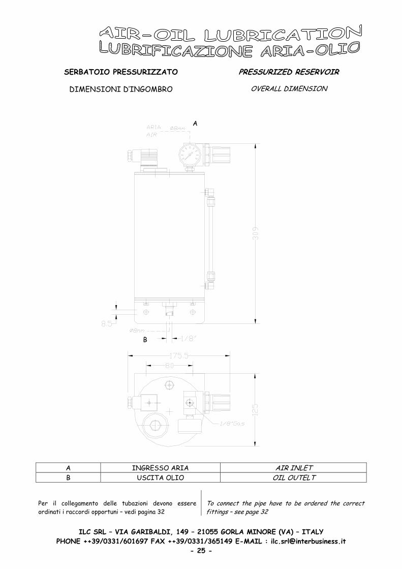
SERBATOIO PRESSURIZZATO PRESSURIZED RESERVOIR
DIMENSIONI D’INGOMBRO OVERALL DIMENSION
A
B
A INGRESSO ARIA AIR INLET B USCITA OLIO OIL OUTELT
Per il collegamento delle tubazioni devono essere ordinati i raccordi opportuni – vedi pagina 32
To connect the pipe have to be ordered the correct fittings – see page 32
PHONE ++39/0331/601697 FAX ++39/0331/365149 E-MAIL : [email protected] - 25 -

ILC SRL – VIA GARIBALDI, 149 – 21055 GORLA MINORE (VA) – ITALY
UNITA’ DA COLLEGARE AL SERBATOIO PRESSURIZZATO
MICROPOMPE CON SENSORE INDUTTIVO PER
CONTROLLO FLUSSO LUBRIFICANTE
UNITS TO BE CONNECTED TO THE PRESSURIZED RESERVOIR
MICRO PUMPS WITH INDUCTIVE SENSOR TO MONITOR THE LUBRICANT
DIMENSIONI D’INGOMBRO OVERALL DIMENSION
CODICE ORDINAZIONE – CODES FOR ORDER
CODICE - CODE MANDATE - DELIVERIES
70.505.2 2 70.505.3 3 70.505.4 4 70.505.5 5 70.505.6 6
A INGRESSO ARIA PER LINEE
SECONDARIE AIR INLET FOR SECONDARY LINES
B INGRESSO OLIO OIL INLET C INGRESSO ARIA COMANDO
POMPE AIR INLET TO DRIVE THE PUMPS
Per il collegamento delle tubazioni devono essere ordinati i raccordi opportuni – vedi pagina 32
To connect the pipe have to be ordered the correct fittings – see page 32
PHONE ++39/0331/601697 FAX ++39/0331/365149 E-MAIL : [email protected] - 26 -

ILC SRL – VIA GARIBALDI, 149 – 21055 GORLA MINORE (VA) – ITALY
UNITA’ DA COLLEGARE ALLE USCITE DELLE POMPE
GRUPPO CONTROLLO PRESSIONE MINIMA
DELL’ARIA
CODICE 70.510.2
UNITS TO BE CONNECTED TO THE MICRO PUMPS OUTLETS
BLOCK TO CHECK LOW AIR PRESSURE
CODE 70.510.2
DIMENSIONI D’INGOMBRO OVERALL DIMENSION
F INGRESSO ARIA/OLIO DALLE MICROPOMPE
AIR/OIL INLET FROM THE MICRO PUMPS
G USCITA ARIA/OLIO PER LE LINEE SECONDARIE
AIR/OIL OUTLET FOR THE SECONDARY LINES
Per il collegamento delle tubazioni devono essere ordinati i raccordi opportuni – vedi pagina 32
To connect the pipe have to be ordered the correct fittings – see page 32
PHONE ++39/0331/601697 FAX ++39/0331/365149 E-MAIL : [email protected] - 27 -
Una volta selezionato il numero di blocchi bisogna ordinare la squadretta necessaria. Once selected the numbers of the block have to be ordered the correct bracket.
ILC SRL – VIA GARIBALDI, 149 – 2
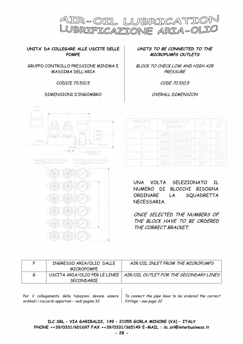
UNITA’ DA COLLEGARE ALLE USCITE DELLE POMPE
GRUPPO CONTROLLO PRESSIONE MINIMA E
MASSIMA DELL’ARIA
CODICE 70.510.5
UNITS TO BE CONNECTED TO THE MICROPUMPS OUTLETS
BLOCK TO CHECK LOW AND HIGH AIR
PRESSURE
CODE 70.510.5
DIMENSIONI D’INGOMBRO OVERALL DIMENSION
F INGRESSO ARIA/OLIO DALLE MICROPOMPE
G USCITA ARIA/OLIO PER LE LINEE SECONDARIE
Per il collegamento delle tubazioni devono essere ordinati i raccordi opportuni – vedi pagina 32
PHONE ++39/0331/601697 FAX ++39/033 - 2
105
AI
Tofi
1/38 -
5 GORLA MINORE (VA) – ITALY
AIR/OIL INLET FROM THE MICROPUMPS
R/OIL OUTLET FOR THE SECONDARY LINES
connect the pipe have to be ordered the correct ttings – see page 32
65149 E-MAIL : [email protected]
UNA VOLTA SELEZIONATO IL NUMERO DI BLOCCHI BISOGNA ORDINARE LA SQUADRETTA NECESSARIA. ONCE SELECTED THE NUMBERS OF THE BLOCK HAVE TO BE ORDERED THE CORRECT BRACKET.

ILC SRL – VIA GARIBALDI, 149 – 21055 GORLA MINORE (VA) – ITALY
ELETTROVALVOLA COMANDO ARIA MICROPOMPE
SOLENOID VALVE TO DRIVE THE MICROPUMPS
DIMENSIONI D’INGOMBRO OVERALL DIMENSION
ELETTROVALVOLE COMANDO ARIA MICROPOMPE E INVIO ARIA AL SISTEMA
SOLENOID VALVES TO DRIVE THE MICROPUMPS AND TO SEND AIR IN THE
SYSTEM
DIMENSIONI D’INGOMBRO OVERALL DIMENSION
PHONE ++39/0331/601697 FAX ++39/0331/365149 E-MAIL : [email protected] - 29 -

ILC SRL – VIA GARIBALDI, 149 – 21055 GORLA MINORE (VA) – ITALY
ELETTROVALVOLE COMANDO ARIA MICROPOMPE, INVIO ARIA AL SISTEMA E
COMANDO POMPA DEL VUOTO
SOLENOID VALVES TO DRIVE THE MICROPUMPS, TO SEND AIR IN THE
SYSTEM AND TO DRIVE THE VACUUM PUMP
DIMENSIONI D’INGOMBRO OVERALL DIMENSION
REGOLATORE PRESSIONE ARIA NELLE LINEE SECONDARIE PER SISTEMI DA 2 A 4 MICROPOMPE
AIR PRESSURE REGULATOR FOR THE SECONDARY LINES FOR SYSTEM FROM 2 UNTIL 4 PUMPS
DIMENSIONI D’INGOMBRO OVERALL DIMENSION
PHONE ++39/0331/601697 FAX ++39/0331/365149 E-MAIL : [email protected] - 30 -

ILC SRL – VIA GARIBALDI, 149 – 21055 GORLA MINORE (VA) – ITALY
REGOLATORE PRESSIONE ARIA NELLE LINEE SECONDARIE PER SISTEMI CON PIU’ DI 4 MICROPOMPE
AIR PRESSURE REGULATOR FOR THE SECONDARY LINES FOR SYSTEM HAVING MORE THAN 4 MICROPUMPS
DIMENSIONI D’INGOMBRO OVERALL DIMENSION
MANOMETRO PER REGOLATORE ARIA PRESSURE GAUGE FOR AIR REGULATOR
DIMENSIONI D’INGOMBRO OVERALL DIMENSION
PHONE ++39/0331/601697 FAX ++39/0331/365149 E-MAIL : [email protected] - 31 -

RACCORDI RAPIDI PUSH-IN FITTINGS
ILC SRL – VIA GARIBALDI, 149 – 21055 GORLA MINORE (VA) – ITALY PHONE ++39/0331/601697 FAX ++39/0331/365149 E-MAIL : [email protected]
- 32 -
ILC SRL – VIA GARIBALDI, 149 – 21055 GORLA MINORE (VA) – ITALY
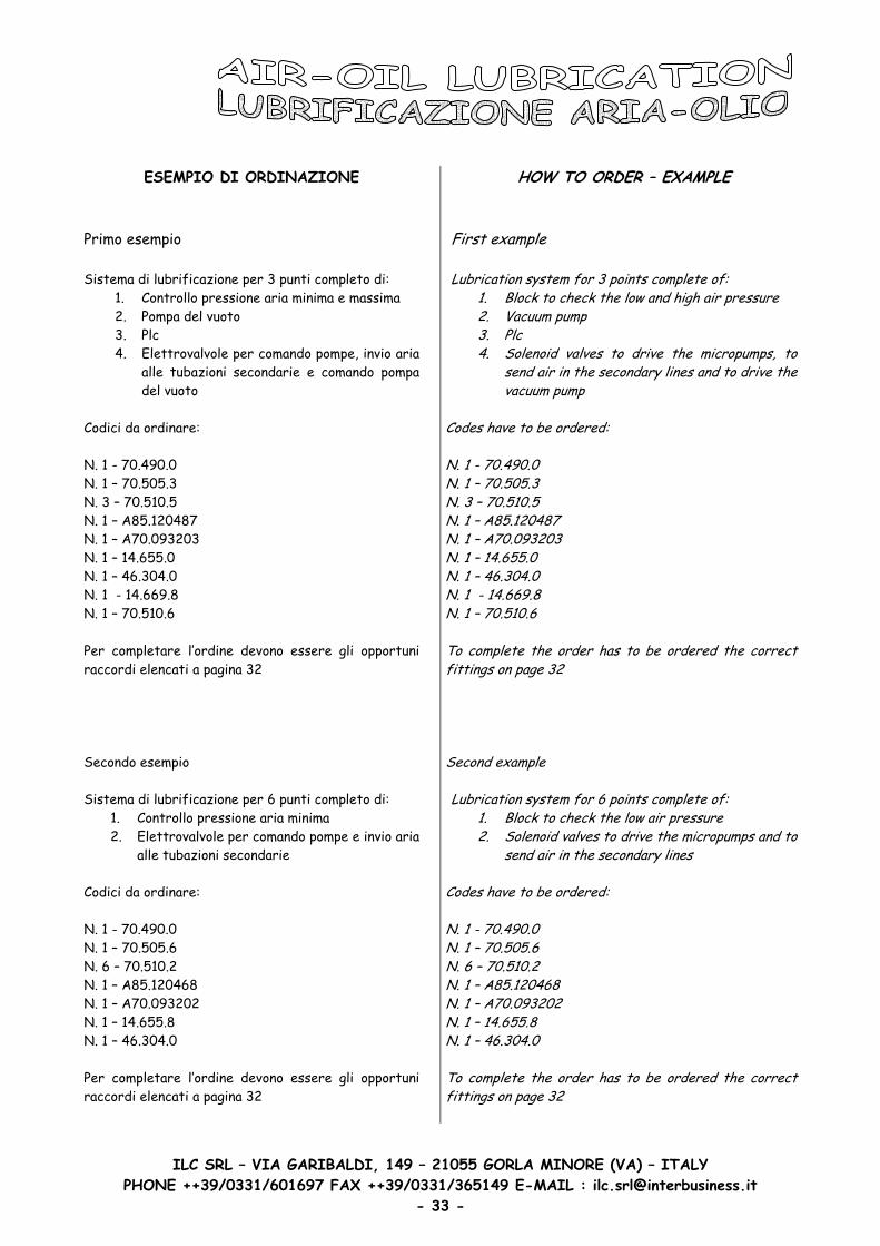
ESEMPIO DI ORDINAZIONE Primo esempio Sistema di lubrificazione per 3 punti completo di:
1. Controllo pressione aria minima e massima 2. Pompa del vuoto 3. Plc 4. Elettrovalvole per comando pompe, invio aria
alle tubazioni secondarie e comando pompa del vuoto
Codici da ordinare: N. 1 - 70.490.0 N. 1 – 70.505.3 N. 3 – 70.510.5 N. 1 – A85.120487 N. 1 – A70.093203 N. 1 – 14.655.0 N. 1 – 46.304.0 N. 1 - 14.669.8 N. 1 – 70.510.6 Per completare l’ordine devono essere gli opportuni raccordi elencati a pagina 32 Secondo esempio Sistema di lubrificazione per 6 punti completo di:
1. Controllo pressione aria minima 2. Elettrovalvole per comando pompe e invio aria
alle tubazioni secondarie Codici da ordinare: N. 1 - 70.490.0 N. 1 – 70.505.6 N. 6 – 70.510.2 N. 1 – A85.120468 N. 1 – A70.093202 N. 1 – 14.655.8 N. 1 – 46.304.0 Per completare l’ordine devono essere gli opportuni raccordi elencati a pagina 32
HOW TO ORDER – EXAMPLE First example Lubrication system for 3 points complete of:
1. Block to check the low and high air pressure 2. Vacuum pump 3. Plc 4. Solenoid valves to drive the micropumps, to
send air in the secondary lines and to drive thevacuum pump
Codes have to be ordered: N. 1 - 70.490.0 N. 1 – 70.505.3 N. 3 – 70.510.5 N. 1 – A85.120487 N. 1 – A70.093203 N. 1 – 14.655.0 N. 1 – 46.304.0 N. 1 - 14.669.8 N. 1 – 70.510.6 To complete the order has to be ordered the correct fittings on page 32 Second example Lubrication system for 6 points complete of:
1. Block to check the low air pressure 2. Solenoid valves to drive the micropumps and to
send air in the secondary lines Codes have to be ordered: N. 1 - 70.490.0 N. 1 – 70.505.6 N. 6 – 70.510.2 N. 1 – A85.120468 N. 1 – A70.093202 N. 1 – 14.655.8 N. 1 – 46.304.0 To complete the order has to be ordered the correct fittings on page 32
PHONE ++39/0331/601697 FAX ++39/0331/365149 E-MAIL : [email protected] - 33 -